PRESTATIEVERKLARING Nr. 0018 NL fischer Ceiling Anchor...
11
PRESTATIEVERKLARING Nr. 0018 – NL 1. Unieke identificatiecode van het producttype: fischer Ceiling Anchor FDN 2. Beoogd(e) gebruik(en): Product Beoogd gebruik Vervorming gecontroleerd spreidanker Voor meervoudig dragende niet constructieve systemen in gescheurd en ongescheurd beton, zie bijlage. 3. Fabrikant: fischerwerke GmbH & Co. KG, Klaus-Fischer-Straße 1, 72178 Waldachtal, Duitsland 4. Gemachtigde: -- 5. Het systeem of de systemen voor de beoordeling en verificatie van de prestatiebestendigheid: 2+ 6a. Geharmoniseerde norm: --- Aangemelde instantie(s): --- 6b. Europees beoordelingsdocument: ETAG 001; 2013-04 Europese technische goedkeuring: ETA-07/0144; 2011-12-13 Technische beoordelingsinstantie: DIBt Aangemelde instantie(s): 1343 – MPA Darmstadt 7. Aangegeven prestatie(s): Veiligheid bij brand (BWR 2) Essentieel kenmerk Prestatie Brandgedrag Verankeringen voldoen aan de vereisten voor klasse A1 Brand weerstand Zie bijlage, in het bijzonder bijlage 3 Veiligheid in gebruik(BWR 4) Essentieel kenmerk Prestatie karakteristieke trek weerstand Zie bijlage, in het bijzonder bijlages 1 - 3 karakteristieke afschuif weerstand Zie bijlage, in het bijzonder bijlages 1 - 3 minimale hoh- en rand-afstand Zie bijlage, in het bijzonder bijlages 1 - 3 8. Geëigende technische documentatie en/of specifieke technische documentatie: --- De prestaties van het hierboven omschreven product zijn conform de aangegeven prestaties. Deze prestatieverklaring wordt in overeenstemming met Verordening (EU) nr. 305/2011 onder de exclusieve verantwoordelijkheid van de hierboven vermelde fabrikant verstrekt. Ondertekend voor en namens de fabrikant door: Andreas Bucher, Dipl.-Ing. Wolfgang Hengesbach, Dipl.-Ing., Dipl.-Wirtsch.-Ing. Tumlingen, 2015-07-27 - Deze prestatieverklaring is opgesteld in verschillende talen. Bij een geschil over de interpretatie prevaleert de engelse versie. - De bijlage bevat vrijwillige en aanvullende informatie in de Engelse taal boven op de (taal-neutraal gespecificeerde) wettelijke voorschriften.
Transcript of PRESTATIEVERKLARING Nr. 0018 NL fischer Ceiling Anchor...
PRESTATIEVERKLARING
Nr. 0018 – NL
1. Unieke identificatiecode van het producttype: fischer Ceiling Anchor FDN
2. Beoogd(e) gebruik(en):
Product Beoogd gebruik
Vervorming gecontroleerd spreidanker Voor meervoudig dragende niet constructieve systemen in gescheurd en
ongescheurd beton, zie bijlage.
3. Fabrikant: fischerwerke GmbH & Co. KG, Klaus-Fischer-Straße 1, 72178 Waldachtal, Duitsland
4. Gemachtigde: --
5. Het systeem of de systemen voor de beoordeling en verificatie van de prestatiebestendigheid: 2+
6a. Geharmoniseerde norm: ---
Aangemelde instantie(s): ---
6b. Europees beoordelingsdocument: ETAG 001; 2013-04
Europese technische goedkeuring: ETA-07/0144; 2011-12-13
Technische beoordelingsinstantie: DIBt
Aangemelde instantie(s): 1343 – MPA Darmstadt
7. Aangegeven prestatie(s):
Veiligheid bij brand (BWR 2)
Essentieel kenmerk Prestatie
Brandgedrag Verankeringen voldoen aan de vereisten voor klasse A1
Brand weerstand Zie bijlage, in het bijzonder bijlage 3
Veiligheid in gebruik(BWR 4)
Essentieel kenmerk Prestatie
karakteristieke trek weerstand Zie bijlage, in het bijzonder bijlages 1 - 3
karakteristieke afschuif weerstand Zie bijlage, in het bijzonder bijlages 1 - 3
minimale hoh- en rand-afstand Zie bijlage, in het bijzonder bijlages 1 - 3
8. Geëigende technische documentatie en/of specifieke technische documentatie: ---
De prestaties van het hierboven omschreven product zijn conform de aangegeven prestaties. Deze prestatieverklaring
wordt in overeenstemming met Verordening (EU) nr. 305/2011 onder de exclusieve verantwoordelijkheid van de hierboven
vermelde fabrikant verstrekt.
Ondertekend voor en namens de fabrikant door:
Andreas Bucher, Dipl.-Ing. Wolfgang Hengesbach, Dipl.-Ing., Dipl.-Wirtsch.-Ing.
Tumlingen, 2015-07-27
- Deze prestatieverklaring is opgesteld in verschillende talen. Bij een geschil over de interpretatie prevaleert de engelse
versie.
- De bijlage bevat vrijwillige en aanvullende informatie in de Engelse taal boven op de (taal-neutraal gespecificeerde)
wettelijke voorschriften.

DeutschesInstHut für Bautechnik
Zulassungsstellefür Beuprodukteund Bauarten
BautechnischesPrüfamt
Eine vom Bund und den Ländern
gemeinsamgetrageneAnstalt desöffentlichenRechts *
*Authorisad
^ sndnottRedacconyngto Arttda 10 oTtheCoLjncfl
OirsOluecf 21 DecemberigBS
onihoBpproximetionofi«we, ^r^utebonsandadministrattv«
piovlstonsof MemMr StatMr»tetir»a to constniction -
' pn>duete(Ba'106€EC) *
DeutschesInstitut
für
Bautechnik DIßt
Kolonnenstraße30 B
D-10829Beriir^
Tel.: +493078730-0
Fax;+493078730-320
E-Mail: dibt^dibt.de
www.dibt.de
Mitglied der EOTA
Memberof EOTA
EuropeanTechnicalApproval ETA-07/0144
English translationpreparedby DIBt • Original version in German Ianguage
HandelsbezeichnungTradename
ZulassungsinhaberHolderof approval
ZulassungsgegenstandundVenvendungszweck
Generictypeanduseof constructionproduct
Geltungsdauer:Validity:
HerstellwerkManufacturingplant
vom
from
bisto
DieseZulassungumfasstThis Approvalcontains
DieseZulassungersetztTosApprovalreplaces
fischerDeckennagelFDN
fischerCeiling AnchorFDN
fischerwerkeGmbH & Co. KG
Weinhalde14-18
72178Waldachtal
WegkontrolliertspreizenderDübelaus galvanischverzinktemStahl fürdieVenwendungals Mehrfachbefestigungvon nichttragenden Systemenin Beton
Deformation-controliedexpansion anchor made ofgalvanisedsteelformultipleusefor non-structuralapplicationsin concrete
21 February2011
12 December2011
fischenwerke
10 Seiteneinschließlich3 Anhänge10pagesincluding3 annexes
ETA-07/0144mit Geltungsdauer vom 03.07.2007 bis 12.12.2011ETA-07/0144 with validityfrom03.07.2007to 12.12.2011
TAZ9255.11
EuropäischeOrganisationfür TechnischeZulassungen
EuropeanOrganisationfor Technical Approvals8.06-01-311/10
Appendix 1/10
DeutschesInstitut
fürBautechnik DIBt
EuropeantechnicalapprovalETA-07/0144
Englishtranslationpreparedby DIBt
Page2 of 10 | 21February2011
Z9255.11
LEGAL BASESAND GENERAL CONDITIONS
This European technical approval is issued by DeutschesInstitut für Bautechnik inaccordancewith:
- Council Directive 89/106/EEC of 21 December1988 on the approximation of laws,regulations andadministrative provisions of Member States relating to constructionproducts\modified by Council Directive 93/68/EEC^andRegulation(EC) N° 1882/2003oftheEuropeanParliamentand of theCouncil®;
- GesetzüberdasIn-Verkehr-Bringen von und den freienWarenverkehrmit BauproduktenzurUmsetzung derRichtlinie 89/106/EWGdes Rates vom 21. Dezember 1988 zurAngleichungder Rechts-und Verw^altungsvorschriftender f^itgliedstaatenüber Bauprodukteund andererRechtsakte der Europäischen Gemeinschaften (Bauproduktengesetz- BauPG) vom28.April 1998*, asamendedby law of 31 October2006®;
• Common Procedural Rules for Requesting, Preparing and the Granting of Europeantechnicalapprovalsseiout in theAnnextoCommissionDecision94/23/EC®:
- Guideline for Europeantechnical approval of "Metalanchorsfor use inconcrete• Part 6:Anchorsfor multiple usefor non-structuralapplications",ETAG 001-06.
DeutschesInstitut für Bautechnikis authorizedto checkwhetherthe provisionsof this Europeantechnical approval are met. Checking may take place in the manufacturing plant. Nevertheless,the responsibilityfor the conformity of the products to the European technical approval and fortheirfitnessfor the intenöeduseremainswith the holderof the Europeantechnicalapproval.
This European technical approval is not to be transferred to manufacturers oragentsofmanufacturersother than those indicatedon page1, or manufacturingplantsotherthan thoseindicatedon page1 of this Europeantechnicalapproval.
This European technical approval may bewithdrawn by DeutschesInstitut für Bautechnik, inparticular pursuant toinformation by the Commission according to Article5(1) ofCouncilDirective 89/106/EEC.
Reproductionof this Europeantechnical approval including transmissionby electronicmeansshall be infuH. However, partial reproduction can bemadewith the writtenconsentof DeutschesInstitut für Bautechnik. In thiscasepartial reproduction has to bedesignatedas such.Texts anddrawings of advertising brochures shall not contradict or misuse the European technicalapproval.
The European technical approval is issued by the approval bodyin its official language. ThisVersion correspondsfully lo the version circulatedwithin EOTA. Translations into otherlanguageshave to bedesignatedassuch.
Official Journalof Ihe EuropeanCommunitlesL 40,11 February1989, p. 12Official Journalof the EuropeanCommunitiesL 220, 30August1993, p. 1Official Journalof the EuropeanUnion L 284, 31October2003, p. 25BundesgesetzblattTeil 11998.p. 812BundesgesetztlaUTeil 12006.p. 2407, 2416Official Journal of the European CommunrtiesL17,20January1994, p. 34
8.06.01-311/10
Appendix 2/10
DeutschesInstitut
für
Bautechnik DIBtEuropeantechnicalapprovalETA-07/0144
Englishtranslationpreparedby DIBtPage3 oM 0 | 21February2011
SPECIFICCONDITIONS OF THE EUROPEANTECHNICAL APPROVAL
1 Definition of theproductandintendeduse
1.1 Definition of theproduct
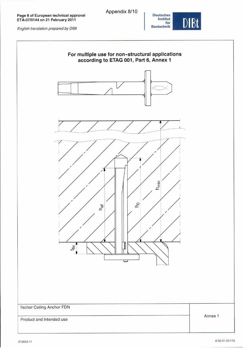
The fischer Ceiling AnchorFDN is an anchormadeof galvanisedsteelwhich is placed into adrilled hole andanchoredby deformation-controlledexpansion.
An illustration ofthe productand intendeduseis given in Annex 1.
1.2 Intendeduse
Theanchoris intendedto be usedfor anchoragesfor which requirementsfor safetyin usein thesenseof the EssentialRequirements4 of Council Directive 89/106 EEC shail befulfilled andfailure of the fixturerepresentsan immediaterisk to humanlife. The anchoris to be usedonlyfor multiple use for non-structural applications. Thedefinition of multiple use accordingto theMemberStatesis given inthe informative Annex 1 of ETAG 001,Part6.
Theanchormay be used foranchorageswith requirementsrelated toresistanceto fire.The anchor is to be used only for anchoragessubject to static or quasi-static loading inreinforcedor unreinforcednormal weightconcreteof strengthclassesC20/25at minimum and050/60at most according to EN206-1:2000-12,It may beanchoredin crackedor non-crackedconcrete.
The anchormayonly be usedin structuressubjectto dry internal conditions.
The provisionsmadein this European technical approval are based on anassumedworking lifeof the anchorof 50 years.The indications given on the working lifecannotbe interpretedasaguarantee given by the producer, but are to be regarded onlyasa meansfor choosing therightproductsin relation tothe expectedeconomicallyreasonableworking life of theworks.
2 Characteristicsof theproductandmethodsof verlfication
2.1 Characteristicsof the product
The anchorcorrespondsto the drawings and provisions given in Annex 2.The characteristicmaterialvalues,dimensionsandtolerancesof the anchornot given in Annex 2shall correspondto the respective values laid down in the technical documentation' of this European technicalapproval.
Regarding the requirementsconcerningsafety in caseof fire it is assumedthat the anchormeets the requirementsof class AI in relation to reaction to fire inaccordancewith thestipulations of theCommissiondecision 96/603/EC,amendedby2000/605/EC.
29255-11
The technicaldocumentationof tfiis European technical approval isdepositedat the DeutschesInstitut für Bautechnikand, as far as relevant for the tasks of the approved bodles involved in theattestationof conformityprocedure,ishandedoverto theapprovedlx>dies.
0.06.01-311/10
Appendix 3/10

DeutschesInstitut
fürBautechnik DIBt
EuropeantechnicalapprovalETA-07/0144 Page4of10|21February2011Englishtranslationpreparedby DIBt
The characteristicvalues for the design of anchoragesare given in Annex 2 and 3. Thecharacteristicvaluesfor the design of theanchoragesregardingresistanceto fire are given inAnnex 3,Table 4. They are valid for use in a systemthat is required to provide a specific fireresistanceclass.
Each headof the anchoris markedwith the identifying mark of the producer,the anchortypeandthe anchorsizeaccordingto Annex 2.
The anchorshall only be supplied as acompleteunit.
2.2 Methodsof verification
The assessmentof fitnessof the anchorfor the intendeduse in relation to the requirementsforsafety in use in thesenseof the Essential Requirements 4 has been made inaccordancewiththe "Guideline forEuropeantechnical approval of Metal Anchors foruse in concrete",Part 1"Anchors in general" and Part 6 "Anchors for multipleusefor non-structural applications".Theassessmentof the anchorfor the intendedusein relation to the requirementsfor resistanceto fire has been made in accordancewith the Technical Report TR 020 "Evaluation ofanchoragesin concreteconcerningresistanceto fire".
In addition to the specificciausesrelating todangeroussubstancescontainedin this Europeantechnical approval, there may be other requirements applicable to the productsfalling within itsscope{e.g. transposedEuropeanlegislationand national laws, regulations andadministrativeprovisions). In order to meet the provisions of the Construction ProductsDirective, theserequirementsneedalsoto be compliedwith, when and wheretheyapply.
3 Evaluationandattestatlonof conformityandCE marking
3.1 Systemof attestationof conformity
According to thedecision97/161/EGof the European Commission' the system2{ii) (referredtoassystem2+) of attestationof conformity applies.
This systemof attestationof conformity is definedasfollows:
System 2+;Declarationof conformityof the product by the manufacturer on the basis of:(a) Tasksfor the manufacturer:
(1) initial type-testingof the product;(2) factory productioncontroi;(3) testing ofsamplestakenat the factory inaccordancewith a controi plan.
(b) Tasksfor the approvedbody;
(4) certification of factory production controi onthebasisof:- initial inspection of factory and of factory production controi;- continuoussurveillance,assessmentandapprovalof factory production
controi.
Note: Approvedbodiesarealso referredto as"notified bodies".
Offlcial Journalof ttie EuropeanCommunitiesL 67 of 03.02.1997
Z92S5.11 fl.06.01-311/10
Appendix 4/10
DeutschesInstitut
für
Bautechnik DIBtEuropeantechnicalapproval
ETA-07/0144 Page5 of 10 | 21 February2011English translationpreparedby DIBt
3.2 Responsibilities
3.2.1 Tasksfor themanufacturer
3.2.1.1 Factoryproductioncontrol
The manufacturershall exercisepermanentinternal control of production. All the elements,requirements and provisions adopted by the manufacturer shall be documented in a systematicmannerin the form of written policies andprocedures,including recordsof resutts periormed.This production controlsystemshall insure that the product ts in conformity with thisEuropeantechnicalapproval.
The manufacturermay only use initial / raw / constituentmaterials stated in the technicaldocumentationof this Europeantechnicalapproval.
The factoryproductioncontrol shall be inaccordancewith the control planwhich is part of thetechnicaldocumentationof this Europeantechnical approval. The control plan is laiddown in thecontext of the factory production controlsystemoperatedby the manufacturerand depositedwith DeutschesInstitut für Bautechnik.®
The results of factory production control shall berecordedand evaluatedin accordancewith theprovisionsof the control pian.
3.2.1.2 Othertasksof manufacturer
The manufacturershall, on the basisof a contract, involve a body which is approvedfor thetasksreferredto in section3.1 in the field of anchorsin orderto undertakethe actionslaid downin section3.2.2. For thispurpose,the control plan referred to insections3.2.1.1 and 3.2.2 shallbehandedover by the manufacturerto the approvedbodyinvolved.
The manufacturershall makea declarationof conformity, statingthat the constructionproductisin conformity withthe provisionsof this Europeantechnicalapproval.
3.2.2 Tasksfor theapprovedbodies
Theapprovedbodyshall performthe
- initial inspectionof factory andof factory productioncontrol,
- continuoussurveillance,assessmentandapprovalof factory productioncontrol,in accordancewith theprovisionslaid down in the control plan.
The approvedbody shall retaintheessentialpoints of its actions referred toaboveand State theresultsobtainedandconclusionsdrawn in a written report.
The approvedcertification body involved by the manufacturer shall issue an EC certificate ofconformity of the factory production control stating the conformity with the provisions of thisEuropeantechnicalapproval.
In caseswhere the provisionsof the Europeantechnical approvaland its control planare nolonger fulfilied the certification body shallwithdraw the certificate ofconformity and informDeutschesInstitut für Bautechnikwithout delay.
3.3 CE marking
The CE marking shall be affixed oneach packaging of the anchor. The letters "CE" shall befollowed by the identification number of theapprovedcertification body,whererelevant, and beaccompaniedby thefollowing additional Information:
- the name and addressof the holder of the approval (legal entity responsiblefor themanufacture),
- the last two digits of the yearin which the CE markingwasaffixed,
* The control plan is aconfidentialpart of theEurope&i technicalapprovalandonly handedoverto theapprovedbodyInvc^ved Intheprocedureof attestationof conformity. Seesection3.2.2.
Z92S5.11 a.06-01-311/10
Appendix 5/10
DeutschesInstitut
fürBautechnik DIBt
EuropeantechnicalapprovaiETA-07/0144 Page6 of 10 | 21February2011English translationpreparedby DIBt
• the numberof the EC certificatefor thefaclory productioncontrol,
- the numberof the Europeantechnicalapprovai,
- the numberof the guideiine forEuropeantechnical approvai(ETAG 001-6),
- size.
4 Assumptionsunderwhich thefitnessof theproductfor the intendedusewasfavourablyassessed
4.1 Manufacturing
The European technical approvai is issued for the product on the basis of agreeddata/information,depositedwith the DeutschesInstitut für Bautechnik, whichidentifies theproduct that hasbeenassessedand judged.Changesto the productor productionprocess,which could result in thisdepositeddata/information being incorrect, should benotified to theDeutschesInstitut für Bautechnik before thechangesare introduced. DeutschesInstitut fürBautechnikwill decide whetheror not such changesaffect theapprovaiand consequentlythevalidity of the CE marking onthe basisof the approvaiand if sowhetherfurther assessmentoralterationsto the approvaishall benecessary.
4.2 Designof anchorages
The fitnessof theanchorfor the intendeduseis given underthefollowing conditions:
The anchoragesare designed inaccordancewith the "Guideline for European technicalapprovai ofMetal Anchors for Use in Concrete", Annex C,Method B under theresponsibilityofan engineerexperiencedin anchoragesandconcretework.
The anchoris to be usedonly for multipleusefor non-structurai applications, thedefinition ofmultiple useaccordingto the MemberStatesis given in the informative Annex 1 ofETAG 001,Part6. The anchormaybesetonly once.
Verifiable caiculation notes and drawingsare preparedtaking account of the loads to beanchored.
The Position of theanchor is indicated on thedesign drawings (e.g. Position of theanchorrelative toreinforcementor to supports).
The design of the fixture issuchthat incaseof excessivesiip or failure of oneanchorthe loadcanbetransmittedto neighbouringanchors.
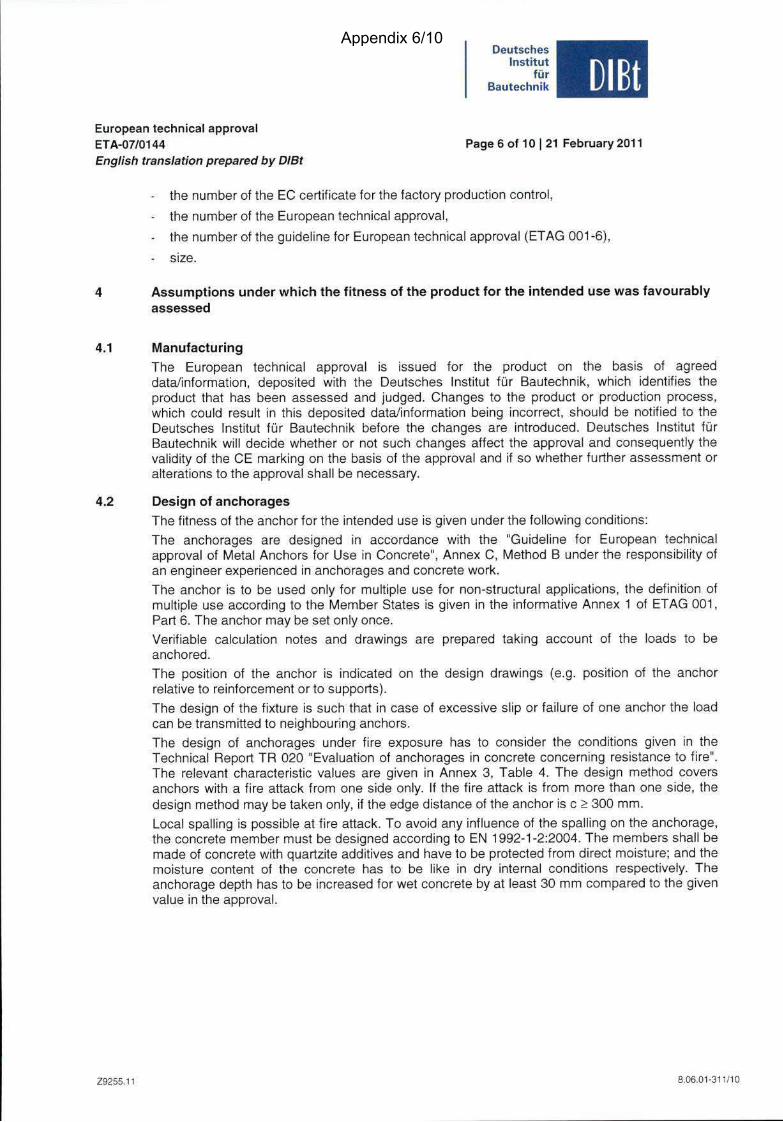
The design ofanchoragesunder fire exposurehas to considerthe conditions given in theTechnical Report TR 020 "Evaluation ofanchoragesin concreteconcerningresistanceto fire".The relevantcharacteristicvalues are given in Annex 3,Table 4. The design method coversanchorswith a fire attackfrom oneside only. If the fire attack is from more than one side, thedesignmethodmay betakenonly, if the edgedistanceof the anchoris c >300mm.
Local spalling ispossibleat fireattack.To avoid any influence of the spailing on theanchorage,the concretemembermust bedesignedaccording to EN1992-1-2:2004.The membersshall bemadeof concretewith quartziteadditivesand haveto be protectedfrom direct moisture;andthemoisture content of the concretehas to be like in dry infernal conditions respectiveiy.Theanchoragedepth hasto be increasedfor wet concreteby at least30 mmcomparedto the givenvaluein theapprovai.
Z985S.11 8.06.01-311/10
Appendix 6/10
DeutschesInstitut
für
Bautechnik DIBtEuropeantechnicalapprovalETA-07/0144 Page7 of 10 | 21February2011Englishtranslationpreparedby DIBt
4.3 Installationof anchors
The fitnessfor useof the anchorcanonly be assumedif the anchoris instaliedasfollows:
- Anchor installation carried out byappropriatelyqualifiedpersonneland under thesupervisionof the personresponsiblefor technicalmattersof the Site.
- Use of theanchoroniy as suppliedby the manufacturerwithout exchangingthe componentsof an anchor.
- Anchor installation inaccordancewith the manufacturer'sspecificationsand drawings andusing the appropriatetools.
- Checksbefore placing theanchorto ensurethat the strengthclassof the concretein whichthe anchoris to be placed is inthe ränge given and is not lower thanthatof the concretetowhich the characteristicloadsapply.
- Checkof concretebeing wellcompacted,e.g. withoutsignificantvoids.
- Edgedistancesandspacingsnot lessthan the specifiedvalueswithout minustolerances.
- Positioningof thedrill holeswithout damagingthe reinforcement.
- In caseof abortedhole: newdrilling at a minimumdistanceaway of twice thedepthof theabortedhole orsmallerdistanceif the aborteddrill hole is fiüed with highstrengthmortarandrf undershearor oblique tension load it is not in the direction of load application.
- Cleaningof the hole.
- Anchor installationsuchthat the effective settingdepth is compliedwith. This complianceisensured, if the thicknessof the fixture is not larger than the maximum values given inAnnex 2.
- Anchor expansionby impact on thewedgeof the anchor. Theanchoris properlyset if thewedgeis fullydropped in.
5 Indicationsto the manufacturer
The manufactureris responsibleto ensure that the information on the specific conditionsaccordingto 1 and 2 including Annexesreferredto and 4.2 and 4.3 is given tothosewho areconcerned.This information may bemade by reproduction of therespectiveparts of theEuropeantechnical approval. In addition all installationdata shall be shown clearly onthepackageand/oron anenclosedinstructionsheet,preferably using illustration(s).The minimum datarequiredare:
- drill bite diameter,
- minimum effectiveanchoragedepth,
- minimum hole depth,
• minimum and maximumthicknessof fixture for the anchortype,
• information on the installationprocedure,preferablyby meansof an illustration,
- referenceto anySpecial installationequipmentneeded,
- identification ofthe manufacturingbatch.All datashall bepresentedin a clearand explicit form.
Georg Feistel beglaubigtHead ofDepartment Baderschneider
Z92S5.11 8.06.01-311/10
Appendix 7/10
Page8 of EuropeantechnicalapprovalETA-07/0144on21 FebruaryZOII
English translationpreparedby DIBt
DeutschesInstitut
für
Bautechnik DIBt
For multiple usefor non-structuralappllcatlonsaccordingto ETAG 001, Part6, Annex1
/I
fischerCeiling Anchor FDN
Productand Intendeduse
Z12603.11
Annex 1
8.06.01-311/10
Appendix 8/10

Page9 of EuropeantechnicalapprovalETA-07/0144on 21 February2011
English translationpreparedby DIBt
0 15
Table1:
//III ll
:£/9
0 15
Dimensionsand materials
DeutschesInstitut
für
Bautechnik DIBt
Li
wedge
shank
1-2
FDN
fischer Ceiling Anchor FDN 6/5 FDN 6/35
Length ofwedge [mm] 43 73
Length ofshank [mm] 39 69,5
Material Steelacc. to EN 10263-4
Table2: Installationparameters
fischer Ceiling Anchor FDN 6/5 FDN 6/35
Diameterof drill hole do [mm] 6
Depthof drill hole ho > [mm] 40
Effective anchoragedepth hgf [mm] 32
Minimum thicknessof member hmin [mm] 80
Maximum thicknessof fixture tfix [mmj 5 35
Minimum spacing Smin [mm] 130
Minimum edgedistance Cmin [mm] 100
fiscber Ceiling Anchor FDN
DimensionsandmaterialsInstallationparameters
212603.11
Annex2
8.06.01-311/10
Appendix 9/10
Page10 of EuropeantechnicalapprovalETA-07/0144on21February2011
English translationpreparedby DIBt
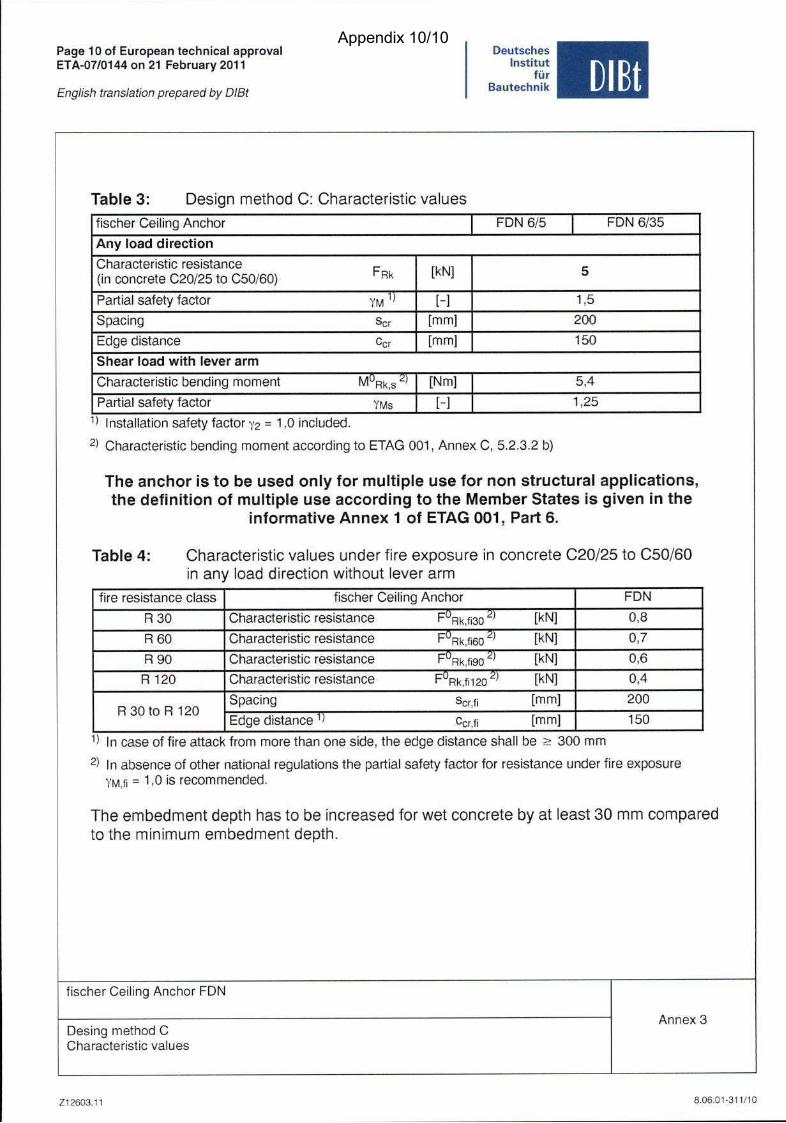
Table3: DesignmethodC: Characteristicvalues
DeutschesInstitut
fürBautechnik DIBt
fischer Ceiling Anchor FDN 6/5 FDN 6/35
Any Ioad direction
Characteristicresistance
(in concreteC20/25to C50/60) f^Rk [kN] 5
Partlalsafetyfactor [-] 1,5
Spacing Scr [mm] 200
Edgedistance Ccr [mml 150
Shearioad with leverarm
Characteristicbendingmoment [Nm] 5,4
Partial safetyfactor YMs [-] 1,25
Installationsafetyfactor72 = 1.0 included.
2) Characteristic bending moment according toETAG 001, Annex C, 5.2.3.2 b)
The anchoris to beusedonly for multiple usefor non structuralapplications,the definitlon of multiple useaccordingto the MemberStatesis given in the
informativeAnnex 1 of ETAG 001, Part6.
Table4: Characteristicvaluesunderfire exposurein concreteC20/25to C50/60in any ioad direction witlnout leverarm
fire resistanceclass fischer Ceiling Anchor FDN
R30 Characteristicresistance F'̂ Rk,f)30 [kN] 0,8
R60 Characteristicresistance P^Rk,fi60 '̂ [kN] 0,7
R90 Characteristicresistance F"Rk,fi90 [kNJ 0,6
R 120 Characteristicresistance F^Rk,fi120 '̂ [kN] 0,4
R30toR120Spacing Scr.fi [mm] 200
Edgedistance''' Ccf.fi [mm] 150
In caseof fire attackfrom more thanoneside, theedgedistanceshall be > 300 mm
In absenceof othernationalregulationsthe partlalsafetyfactor for resistanceunder fireexposureYM,fi = 1-0 isrecommended.
Theembedmentdepthhasto be increasedfor wet concreteby at least30 mm comparedto the minimum embedmentdepth.
fischerCeiling Anchor FDN
DesingmethodCCharacteristicvalues
Z12603.11
Annex 3
8.06.01-311/10
Appendix 10/10