P-3009-BG 700 SS
24
Installation and Operation 700 Series Single and Double Reductions P-3009-BG Doc. No. 57746 Boston Gear ® Worm Gear Speed Reducers An Altra Industrial Motion Company
-
Upload
juan-alejandro-jurado-de-la-rosa -
Category
Documents
-
view
233 -
download
0
Transcript of P-3009-BG 700 SS
Installation and Operation
700 SeriesSingle and DoubleReductions
P-3009-BG
Doc. No. 57746
Boston Gear®
Worm Gear Speed Reducers
An Altra Industrial Motion Company
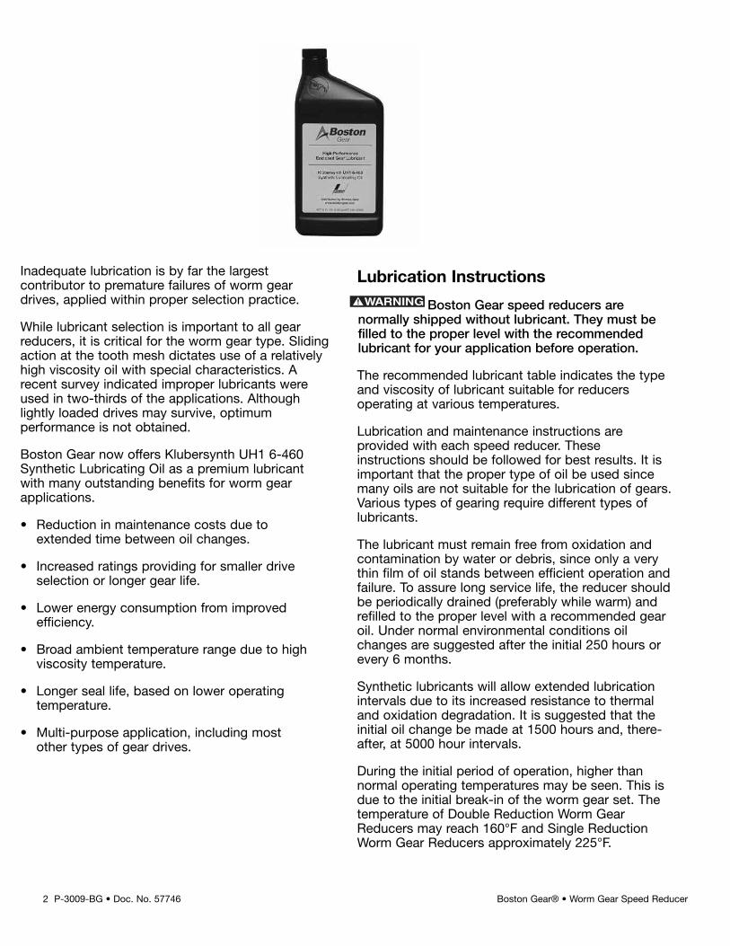
Inadequate lubrication is by far the largestcontributor to premature failures of worm geardrives, applied within proper selection practice.
While lubricant selection is important to all gearreducers, it is critical for the worm gear type. Slidingaction at the tooth mesh dictates use of a relativelyhigh viscosity oil with special characteristics. Arecent survey indicated improper lubricants wereused in two-thirds of the applications. Althoughlightly loaded drives may survive, optimumperformance is not obtained.
Boston Gear now offers Klubersynth UH1 6-460Synthetic Lubricating Oil as a premium lubricantwith many outstanding benefits for worm gearapplications.
• Reduction in maintenance costs due toextended time between oil changes.
• Increased ratings providing for smaller driveselection or longer gear life.
• Lower energy consumption from improvedefficiency.
• Broad ambient temperature range due to highviscosity temperature.
• Longer seal life, based on lower operatingtemperature.
• Multi-purpose application, including mostother types of gear drives.
Lubrication Instructions
Boston Gear speed reducers arenormally shipped without lubricant. They must befilled to the proper level with the recommendedlubricant for your application before operation.
The recommended lubricant table indicates the typeand viscosity of lubricant suitable for reducersoperating at various temperatures.
Lubrication and maintenance instructions areprovided with each speed reducer. Theseinstructions should be followed for best results. It isimportant that the proper type of oil be used sincemany oils are not suitable for the lubrication of gears.Various types of gearing require different types oflubricants.
The lubricant must remain free from oxidation andcontamination by water or debris, since only a verythin film of oil stands between efficient operation andfailure. To assure long service life, the reducer shouldbe periodically drained (preferably while warm) andrefilled to the proper level with a recommended gearoil. Under normal environmental conditions oilchanges are suggested after the initial 250 hours orevery 6 months.
Synthetic lubricants will allow extended lubricationintervals due to its increased resistance to thermaland oxidation degradation. It is suggested that theinitial oil change be made at 1500 hours and, there-after, at 5000 hour intervals.
During the initial period of operation, higher thannormal operating temperatures may be seen. This isdue to the initial break-in of the worm gear set. Thetemperature of Double Reduction Worm GearReducers may reach 160°F and Single ReductionWorm Gear Reducers approximately 225°F.
2 P-3009-BG • Doc. No. 57746 Boston Gear® • Worm Gear Speed Reducer
P-3009-BG • Doc. No. 57746 3Boston Gear® • Worm Gear Speed Reducer
These instructions must be read thoroughly beforeinstalling or operating speed reducers. Fileinstructions for future reference and for ordering ofreplacement parts.
General Instructions
1. Align all shafts accurately. Improper alignmentcan result in failure. Use of flexible couplings isrecommended to compensate for slightmisalignment.
2. When mounting, use maximum possible boltsize and secure reducer to a rigid foundation.Periodic inspection of all bolts is recommended.
3. Auxiliary drive components (such as sprockets,gears and pulleys) should be mounted on theshafts as close as possible to the housing tominimize effects of overhung loads. Avoidforce fits that might damage bearings or gears.
4. For hollow-shaft speed reducers, place speedreducer as close as possible to supportingbearing on drive shaft. Spot-drill driven shaftfor setscrews in severe applications. See kitinstructions for reaction rod assembly.
5. Check and record gear backlash at installationand again at regular intervals. This should bedone by measuring the rotary movement of theoutput shaft (rotating alternately clockwise andcounterclockwise) at a suitable radius whileholding the input shaft stationary. Gears shouldbe replaced when the backlash exceeds fourtimes the measurement taken at installation.
6. Gear drives are rated for 1750 input RPM andClass I Service (Service Factor 1.0), usingKlubersynth UH1 6-460 synthetic lubricant. Forlower input speeds or for different serviceclasses or lubricants, see catalog selectionpages for rating information.
7. Initial operating temperatures may be higherthan normal during the break-in period of thegear set. FOR MAXIMUM LIFE, DO NOTALLOW THE SPEED REDUCER TO OPERATECONTINUOUSLY ABOVE 225°F AT THE GEARCASE. In the event of overheating, check foroverloads or high ambient temperatures. Keepshafts and vent plugs clean to prevent foreignparticles from entering seals or gear housing.
8. All reducers should be checked to see if theyhave been lubricated. Prelubed 700 Seriesreducers will have a solid plug in the vent holewhich must be replaced by the vent plug attime of installation.
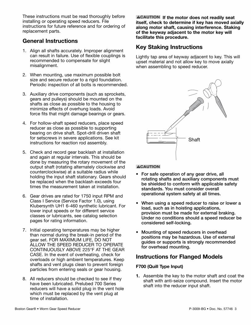
If the motor does not readily seatitself, check to determine if key has moved axiallyalong motor shaft, causing interference. Stakingof the keyway adjacent to the motor key willfacilitate this procedure.
Key Staking Instructions
Lightly tap area of keyway adjacent to key. This willupset material and not allow key to move axiallywhen assembling to speed reducer.
• For safe operation of any gear drive, allrotating shafts and auxiliary components mustbe shielded to conform with applicable safetystandards. You must consider overalloperational system safety at all times.
• When using a speed reducer to raise or lower aload, such as in hoisting applications,provision must be made for external braking.Under no conditions should a speed reducer beconsidered self-locking.
• Mounting of speed reducers in overheadpositions may be hazardous. Use of externalguides or supports is strongly recommendedfor overhead mounting.
Instructions for Flanged Models
F700 (Quill Type Input)
1. Assemble the key to the motor shaft and coat theshaft with anti-seize compound. Insert the motorshaft into the reducer input shaft.
Shaft
2. Rotate the motor to proper position and firmlysecure to flange with four hex-head cap screws.
RF700 (Coupling Input – 3-Jaw Type)
1. Coat reducer input and motor shaft withanti-seize compound.
2. Position coupling half on input shaft with shaftflush to end of coupling bore.
3. Locate remaining half on motor shaft, with 1/32"clearance between jaw surfaces.
4. Tighten setscrews securely. For reversingapplications, a thread-locking compound isrecommended.
5. Install coupling insert and position motor. Rotatemotor to proper position and firmly secure toflange.
QC700 (Coupling Input-3-Jaw QuickConnect Type)
1. Coat motor shaft with anti-seize compound.
2. Install motor coupling half onto motor shaft. Usea straight edge to align coupling jaw top endflush with motor shaft except 738-B9 which willbe flush with bottom of jaw. Secure withset screw.
3. Install urethane spider insert on motor couplinghalf.
4. Insert D-Bore coupling half into urethane spiderelement.
5. Rotate reducer input shaft so “milled flats” areeither vertical or parallel. Rotate motor couplingD-Bore to match the reducer milled flats. Coat“D” flats with anti-seize compound furnished withspeed reducer.
6. Insert motor assembly into reducer flangeassembly. Minor rotating of the motor may benecessary to facilitate D-Bore alignment.
7. Once aligned, push motor towards reducer untilproperly seated against the face of the reducerflange.
8. Insert (4) hex head cap screws into thedesignated locations and securely tightened.
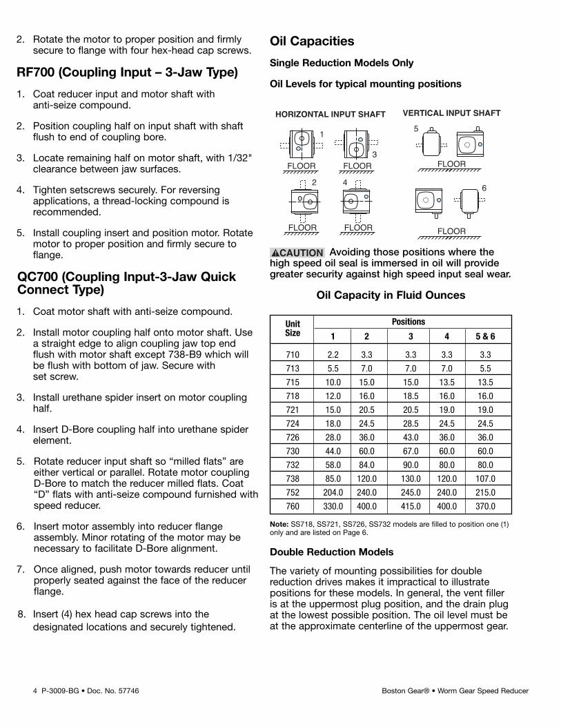
Oil Capacities
Single Reduction Models Only
Oil Levels for typical mounting positions
Note: SS718, SS721, SS726, SS732 models are filled to position one (1)only and are listed on Page 6.
The variety of mounting possibilities for doublereduction drives makes it impractical to illustratepositions for these models. In general, the vent filleris at the uppermost plug position, and the drain plugat the lowest possible position. The oil level must beat the approximate centerline of the uppermost gear.
4 P-3009-BG • Doc. No. 57746 Boston Gear® • Worm Gear Speed Reducer
FLOOR FLOOR
FLOOR FLOOR
1
2 4
HORIZONTAL INPUT SHAFT
3
6
FLOOR
FLOOR
5
VERTICAL INPUT SHAFT
Avoiding those positions where thehigh speed oil seal is immersed in oil will providegreater security against high speed input seal wear.
Oil Capacity in Fluid Ounces
Unit PositionsSize 1 2 3 4 5 & 6
710 2.2 3.3 3.3 3.3 3.3
713 5.5 7.0 7.0 7.0 5.5
715 10.0 15.0 15.0 13.5 13.5
718 12.0 16.0 18.5 16.0 16.0
721 15.0 20.5 20.5 19.0 19.0
724 18.0 24.5 28.5 24.5 24.5
726 28.0 36.0 43.0 36.0 36.0
730 44.0 60.0 67.0 60.0 60.0
732 58.0 84.0 90.0 80.0 80.0
738 85.0 120.0 130.0 120.0 107.0
752 204.0 240.0 245.0 240.0 215.0
760 330.0 400.0 415.0 400.0 370.0
Double Reduction Models
P-3009-BG • Doc. No. 57746 5Boston Gear® • Worm Gear Speed Reducer
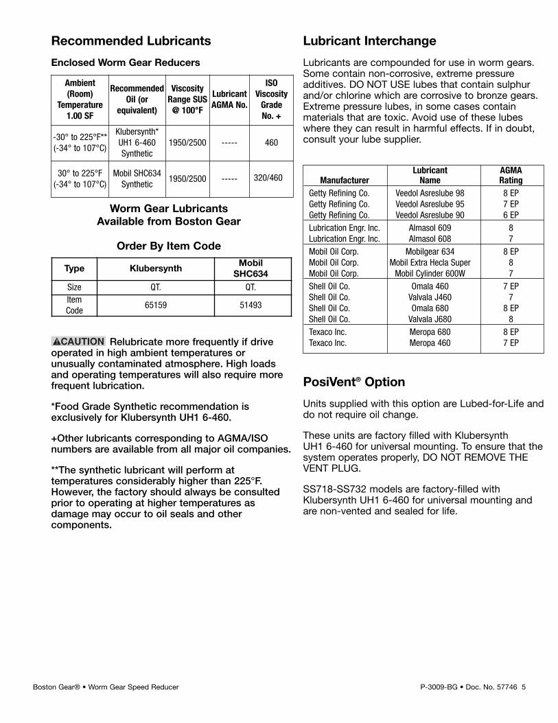
Recommended Lubricants
Enclosed Worm Gear Reducers
Relubricate more frequently if driveoperated in high ambient temperatures orunusually contaminated atmosphere. High loadsand operating temperatures will also require morefrequent lubrication.
*Food Grade Synthetic recommendation isexclusively for Klubersynth UH1 6-460.
+Other lubricants corresponding to AGMA/ISOnumbers are available from all major oil companies.
**The synthetic lubricant will perform attemperatures considerably higher than 225°F.However, the factory should always be consultedprior to operating at higher temperatures asdamage may occur to oil seals and othercomponents.
Ambient(Room)
Temperature1.00 SF
RecommendedOil (or
equivalent)
ViscosityRange SUS@ 100°F
LubricantAGMA No.
ISOViscosityGradeNo. +
-30° to 225°F**(-34° to 107°C)
Klubersynth*UH1 6-460Synthetic
1950/2500 ----- 460
30° to 225°F(-34° to 107°C)
Mobil SHC634Synthetic
1950/2500 ----- 320/460
Type KlubersynthMobilSHC634
Size QT. QT.ItemCode
65159 51493
Worm Gear LubricantsAvailable from Boston Gear
Order By Item Code
Lubricant AGMAManufacturer Name Rating
Getty Refining Co. Veedol Asreslube 98 8 EPGetty Refining Co. Veedol Asreslube 95 7 EPGetty Refining Co. Veedol Asreslube 90 6 EPLubrication Engr. Inc. Almasol 609 8Lubrication Engr. Inc. Almasol 608 7Mobil Oil Corp. Mobilgear 634 8 EPMobil Oil Corp. Mobil Extra Hecla Super 8Mobil Oil Corp. Mobil Cylinder 600W 7Shell Oil Co. Omala 460 7 EPShell Oil Co. Valvala J460 7Shell Oil Co. Omala 680 8 EPShell Oil Co. Valvala J680 8Texaco Inc. Meropa 680 8 EPTexaco Inc. Meropa 460 7 EP
Lubricant Interchange
Lubricants are compounded for use in worm gears.Some contain non-corrosive, extreme pressureadditives. DO NOT USE lubes that contain sulphurand/or chlorine which are corrosive to bronze gears.Extreme pressure lubes, in some cases containmaterials that are toxic. Avoid use of these lubeswhere they can result in harmful effects. If in doubt,consult your lube supplier.
PosiVent® Option
Units supplied with this option are Lubed-for-Life anddo not require oil change.
These units are factory filled with KlubersynthUH1 6-460 for universal mounting. To ensure that thesystem operates properly, DO NOT REMOVE THEVENT PLUG.
SS718-SS732 models are factory-filled withKlubersynth UH1 6-460 for universal mounting andare non-vented and sealed for life.
6 P-3009-BG • Doc. No. 57746 Boston Gear® • Worm Gear Speed Reducer
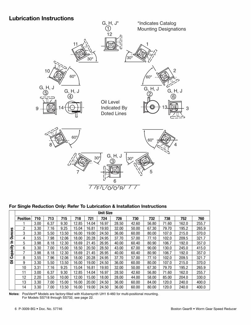
Unit SizePosition 710 713 715 718 721 724 726 730 732 738 752 760
1 3.00 6.37 9.30 12.85 14.04 16.97 28.50 42.60 56.80 71.60 162.0 255.72 3.30 7.16 9.25 15.04 16.81 19.93 32.00 50.00 67.30 79.70 195.2 265.93 3.30 5.50 13.50 16.00 19.00 24.50 36.00 60.00 80.00 107.0 215.0 370.04 3.55 7.98 12.06 18.00 20.28 24.95 37.70 57.00 77.10 102.0 209.5 321.75 3.98 8.18 12.30 18.69 21.45 26.95 40.00 60.40 80.90 106.7 192.0 357.06 3.30 7.00 15.00 18.50 20.50 28.50 43.00 67.00 90.00 130.0 245.0 415.07 3.98 8.18 12.30 18.69 21.45 26.95 40.00 60.40 80.90 106.7 192.0 357.08 3.55 7.96 12.06 18.00 20.28 24.95 37.70 57.00 77.10 102.0 209.5 321.79 3.30 5.50 13.50 16.00 19.00 24.50 36.00 60.00 80.00 107.0 215.0 370.010 3.31 7.16 9.25 15.04 16.81 19.93 32.00 50.00 67.30 79.70 195.2 265.911 3.00 6.37 9.30 12.85 14.04 16.97 28.50 42.60 56.80 71.60 162.0 255.712 2.20 5.50 10.00 12.00 15.00 18.00 28.00 44.00 58.00 85.00 204.0 330.013 3.30 7.00 15.00 16.00 20.00 24.50 36.00 60.00 84.00 120.0 240.0 400.014 3.30 7.00 13.50 16.00 19.00 24.50 36.00 60.00 80.00 120.0 240.0 400.0
OilC
apacity
InOu
nces
For Single Reduction Only: Refer To Lubrication & Installation Instructions
F L O O R6
7
8
9
10
11
12
1
2
3
4
5
G, H, J3
30º
60º
60º
30º 30º
60º
30º
60º
Oil LevelIndicated ByDoted Lines
14
54
G, H, JG, H, J G, H, JG, H, J
G, H, J*
2 6
1
13
*Indicates CatalogMounting Designations
Notes: PosiVent® Models are factory-filled with Klubersynth UH1 6-460 for multi-positional mounting.For Models SS718 through SS732, see page 22.
Lubrication Instructions
P-3009-BG • Doc. No. 57746 7Boston Gear® • Worm Gear Speed Reducer
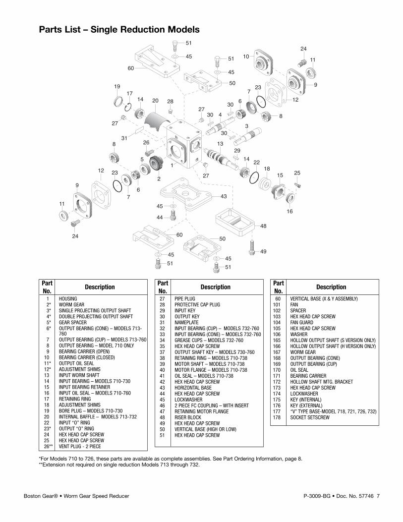
Parts List – Single Reduction Models
2914 22
1815 25
16
13
23
8
5
26
2
67
12
9
11
24
1024
11
9
12
8
237
6
60
45
51
45
51
50
1714 20 28
27
31
19
27
1
27
4345
44
60
4551
4551
49
48
50
30 4
303
30
Part DescriptionNo.1 HOUSING2* WORM GEAR3* SINGLE PROJECTING OUTPUT SHAFT4* DOUBLE PROJECTING OUTPUT SHAFT5* GEAR SPACER6* OUTPUT BEARING (CONE) – MODELS 713-
7607 OUTPUT BEARING (CUP) – MODELS 713-7608 OUTPUT BEARING – MODEL 710 ONLY9 BEARING CARRIER (OPEN)
10 BEARING CARRIER (CLOSED)11* OUTPUT OIL SEAL12* ADJUSTMENT SHIMS13 INPUT WORM SHAFT14 INPUT BEARING – MODELS 710-73015 INPUT BEARING RETAINER16 INPUT OIL SEAL – MODELS 710-76017 RETAINING RING18 ADJUSTMENT SHIMS19 BORE PLUG – MODELS 710-73020 INTERNAL BAFFLE – MODELS 713-73222 INPUT “O” RING23* OUTPUT “O” RING24 HEX HEAD CAP SCREW25 HEX HEAD CAP SCREW26** VENT PLUG - 2 PIECE
Part DescriptionNo.27 PIPE PLUG28 PROTECTIVE CAP PLUG29 INPUT KEY30 OUTPUT KEY31 NAMEPLATE32 INPUT BEARING (CUP) – MODELS 732-76033 INPUT BEARING (CONE) – MODELS 732-76034 GREASE CUPS – MODELS 732-76035 HEX HEAD CAP SCREW37 OUTPUT SHAFT KEY – MODELS 730-76038 RETAINING RING – MODELS 710-73839 MOTOR SHAFT – MODELS 710-73840 MOTOR FLANGE – MODELS 710-73841 OIL SEAL – MODELS 710-73842 HEX HEAD CAP SCREW43 HORIZONTAL BASE44 HEX HEAD CAP SCREW45 LOCKWASHER46 2 PIECE FC COUPLING – WITH INSERT47 RETAINING MOTOR FLANGE48 RISER BLOCK49 HEX HEAD CAP SCREW50 VERTICAL BASE (HIGH OR LOW)51 HEX HEAD CAP SCREW
Part DescriptionNo.60 VERTICAL BASE (X & Y ASSEMBLY)
101 FAN102 SPACER103 HEX HEAD CAP SCREW104 FAN GUARD105 HEX HEAD CAP SCREW106 WASHER165 HOLLOW OUTPUT SHAFT (S VERSION ONLY)166 HOLLOW OUTPUT SHAFT (H VERSION ONLY)167 WORM GEAR168 OUTPUT BEARING (CONE)169 OUTPUT BEARING (CUP)170 OIL SEAL171 BEARING CARRIER172 HOLLOW SHAFT MTG. BRACKET173 HEX HEAD CAP SCREW174 LOCKWASHER175 KEY (INTERNAL)176 KEY (EXTERNAL)177 “V” TYPE BASE-MODEL 718, 721, 726, 732)178 SOCKET SETSCREW
*For Models 710 to 726, these parts are available as complete assemblies. See Part Ordering Information, page 8.**Extension not required on single reduction Models 713 through 732.
8 P-3009-BG • Doc. No. 57746 Boston Gear® • Worm Gear Speed Reducer
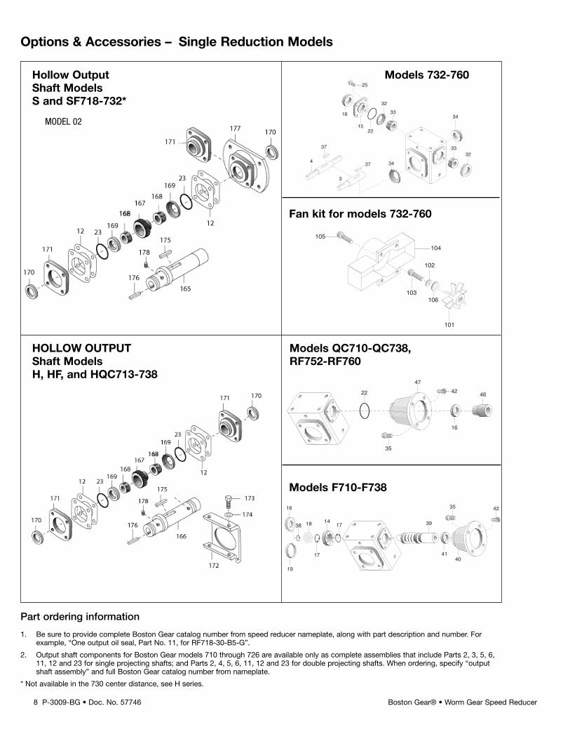
Options & Accessories – Single Reduction Models
Hollow Output Models 732-760Shaft ModelsS and SF718-732*
Fan kit for models 732-760
HOLLOW OUTPUT Models QC710-QC738,Shaft Models RF752-RF760H, HF, and HQC713-738
15
16
25
22
3233
34
3332
3437
37
4
3
105
104
102
103106
101
16
38 18 14 17
17
19
39
35 42
4140
4222
35
16
47
46
Part ordering information
1. Be sure to provide complete Boston Gear catalog number from speed reducer nameplate, along with part description and number. Forexample, “One output oil seal, Part No. 11, for RF718-30-B5-G”.
2. Output shaft components for Boston Gear models 710 through 726 are available only as complete assemblies that include Parts 2, 3, 5, 6,11, 12 and 23 for single projecting shafts; and Parts 2, 4, 5, 6, 11, 12 and 23 for double projecting shafts. When ordering, specify “outputshaft assembly” and full Boston Gear catalog number from nameplate.
* Not available in the 730 center distance, see H series.
MODEL 02
Models F710-F738
P-3009-BG • Doc. No. 57746 9Boston Gear® • Worm Gear Speed Reducer
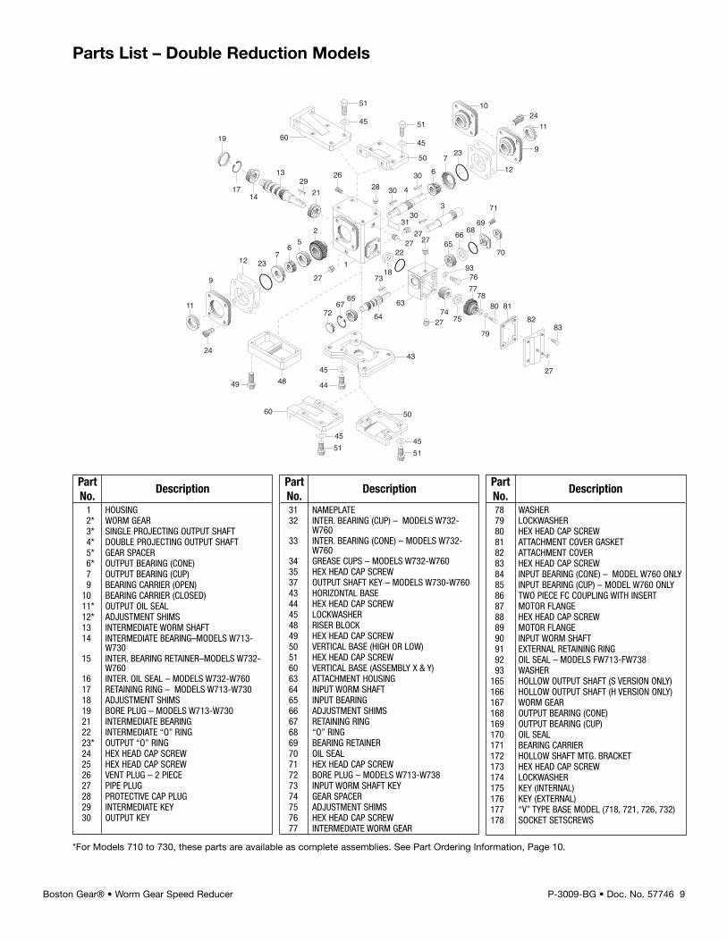
Parts List – Double Reduction Models
2921
13
23
52
67
12
9
11
24
102411
9
12
237
6
60
45
51
45
51
50
2727
30 4
303
1714
19
271
49 48
31
30
4345
44
60
4551
4551
50
686665
69
27
2774
75
7776
78
93
79
80 81
83
27
70
71
82
63
7318
22
64
6567
72
2628
*For Models 710 to 730, these parts are available as complete assemblies. See Part Ordering Information, Page 10.
Part DescriptionNo.1 HOUSING2* WORM GEAR3* SINGLE PROJECTING OUTPUT SHAFT4* DOUBLE PROJECTING OUTPUT SHAFT5* GEAR SPACER6* OUTPUT BEARING (CONE)7 OUTPUT BEARING (CUP)9 BEARING CARRIER (OPEN)
10 BEARING CARRIER (CLOSED)11* OUTPUT OIL SEAL12* ADJUSTMENT SHIMS13 INTERMEDIATE WORM SHAFT14 INTERMEDIATE BEARING–MODELS W713-
W73015 INTER. BEARING RETAINER–MODELS W732-
W76016 INTER. OIL SEAL – MODELS W732-W76017 RETAINING RING – MODELS W713-W73018 ADJUSTMENT SHIMS19 BORE PLUG – MODELS W713-W73021 INTERMEDIATE BEARING22 INTERMEDIATE “O” RING23* OUTPUT “O” RING24 HEX HEAD CAP SCREW25 HEX HEAD CAP SCREW26 VENT PLUG – 2 PIECE27 PIPE PLUG28 PROTECTIVE CAP PLUG29 INTERMEDIATE KEY30 OUTPUT KEY
Part DescriptionNo.31 NAMEPLATE32 INTER. BEARING (CUP) – MODELS W732-
W76033 INTER. BEARING (CONE) – MODELS W732-
W76034 GREASE CUPS – MODELS W732-W76035 HEX HEAD CAP SCREW37 OUTPUT SHAFT KEY – MODELS W730-W76043 HORIZONTAL BASE44 HEX HEAD CAP SCREW45 LOCKWASHER48 RISER BLOCK49 HEX HEAD CAP SCREW50 VERTICAL BASE (HIGH OR LOW)51 HEX HEAD CAP SCREW60 VERTICAL BASE (ASSEMBLY X & Y)63 ATTACHMENT HOUSING64 INPUT WORM SHAFT65 INPUT BEARING66 ADJUSTMENT SHIMS67 RETAINING RING68 “O” RING69 BEARING RETAINER70 OIL SEAL71 HEX HEAD CAP SCREW72 BORE PLUG – MODELS W713-W73873 INPUT WORM SHAFT KEY74 GEAR SPACER75 ADJUSTMENT SHIMS76 HEX HEAD CAP SCREW77 INTERMEDIATE WORM GEAR
Part DescriptionNo.78 WASHER79 LOCKWASHER80 HEX HEAD CAP SCREW81 ATTACHMENT COVER GASKET82 ATTACHMENT COVER83 HEX HEAD CAP SCREW84 INPUT BEARING (CONE) – MODEL W760 ONLY85 INPUT BEARING (CUP) – MODEL W760 ONLY86 TWO PIECE FC COUPLING WITH INSERT87 MOTOR FLANGE88 HEX HEAD CAP SCREW89 MOTOR FLANGE90 INPUT WORM SHAFT91 EXTERNAL RETAINING RING92 OIL SEAL – MODELS FW713-FW73893 WASHER
165 HOLLOW OUTPUT SHAFT (S VERSION ONLY)166 HOLLOW OUTPUT SHAFT (H VERSION ONLY)167 WORM GEAR168 OUTPUT BEARING (CONE)169 OUTPUT BEARING (CUP)170 OIL SEAL171 BEARING CARRIER172 HOLLOW SHAFT MTG. BRACKET173 HEX HEAD CAP SCREW174 LOCKWASHER175 KEY (INTERNAL)176 KEY (EXTERNAL)177 “V” TYPE BASE MODEL (718, 721, 726, 732)178 SOCKET SETSCREWS
10 P-3009-BG • Doc. No. 57746 Boston Gear® • Worm Gear Speed Reducer
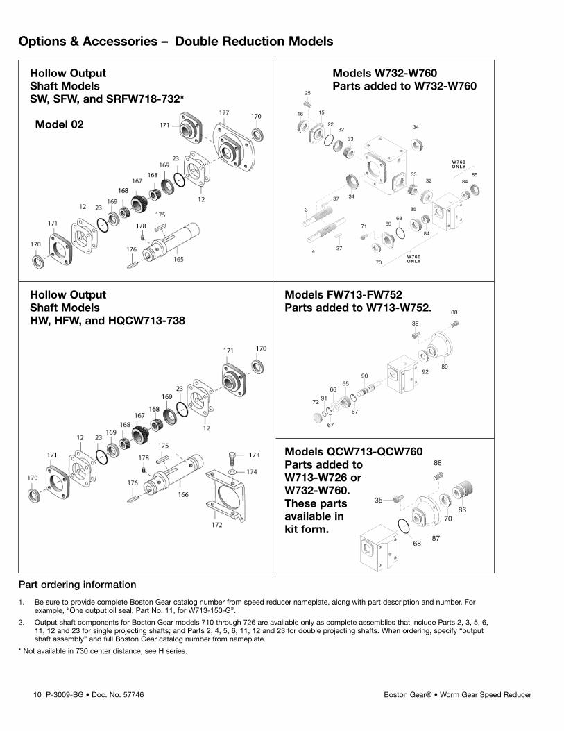
Options & Accessories – Double Reduction Models
Hollow Output Models W732-W760Shaft Models Parts added to W732-W760SW, SFW, and SRFW718-732*
Hollow Output Models FW713-FW752Shaft Models Parts added to W713-W752.HW, HFW, and HQCW713-738
Models QCW713-QCW760Parts added toW713-W726 orW732-W760.These partsavailable inkit form.
1516
25
2232
33
34
71 6968
85
70
84
848533
32
W760ONLY
W760ONLY
3437
374
3
70
88
35
8768
86
88
35
72
9065
6691
67
67
8992
Model 02
Part ordering information
1. Be sure to provide complete Boston Gear catalog number from speed reducer nameplate, along with part description and number. Forexample, “One output oil seal, Part No. 11, for W713-150-G”.
2. Output shaft components for Boston Gear models 710 through 726 are available only as complete assemblies that include Parts 2, 3, 5, 6,11, 12 and 23 for single projecting shafts; and Parts 2, 4, 5, 6, 11, 12 and 23 for double projecting shafts. When ordering, specify “outputshaft assembly” and full Boston Gear catalog number from nameplate.
* Not available in 730 center distance, see H series.
P-3009-BG • Doc. No. 57746 11Boston Gear® • Worm Gear Speed Reducer
Output Shaft Disassembly
1. Remove vented filler (Item 26), and the mostconvenient pipe plug (Item 27) and completelydrain oil.
2. Remove bearing carrier screws (Item 24) fromprojecting shaft bearing carrier (Item 9). Removecarrier by CAREFULLY sliding it over theprojecting shaft diameter.
3. Output shaft assembly (Items 2, 3, 5 & 6) can nowbe removed from the unit. Exercise care not tonick or scratch worm gear or shaft diameters.
4. Visually examine the output shaft assembly.Check tapered roller bearings (Item 6) for signs ofmetallic contamination or discoloration. Rollersshould have continuously smooth action andshould not bind or exhibit “flat-spots”.
5. Note that replacement parts for output gear (Item2) will include an output shaft assembly (Items 3OR 4) for sizes F710 through F726. Also includedare items 5, 6, 11, 12 and 23.
Input Shaft Disassembly
Models F710 through F730
1. With a screwdriver or suitable tool, pierce thebore plug (Item 19) and remove from the housingbore.
Models F732 and F738 only
2. Remove fan guard (Item 104). Remove fanretaining screw (Item 103), fan (Item 101) andspacer. With a screw-driver or suitable tool, pierceand fan end oil seal (Item 16) and remove fromthe housing bore.
3. Remove the outboard retaining ring (Item 17) fromthe housing bore. Remove the metal shims (Item18), located between the retaining ring and theball bearing (Item 14).
4. Remove four (4) screws (Item 42) from the motorflange (Item 40) and remove the flange from thehousing.
5. Remove the input worm assembly (Items 14, 38and 39) through the bore opposite the flange side.Remove the oil seal (Item 41) from the housing.
6. Check the condition of the ball bearing (Item 14).The bearing should roll smoothly and not bind. Ifthe bearing needs replacement, remove the snapring (Item 38) and press the shaft through thebearing. Install new bearing onto the shaft andre-assemble the snap ring. If the bearing is notpre-packed with grease, pack at least 50% fullwith Mobilux EP #2 All Purpose Grease orequivalent.
Input Shaft Reassembly
Models F710 through F738
1. Insert input worm assembly in the housing. Seatthe ball bearing against the inner retaining ring(Item 17).
2. Install the metal shims (Item 18) and assembleoutboard snap ring (Item 17).
3. Clean the housing bore(s) in the area where oilseals will be installed.
4. Coat the oil seals as follows:
A. Rubber Clad Oil Seals - Apply ALL-PURPOSEgrease (NLGI #2 consistency) to the I.D.
B. Steel Clad Oil Seals - Apply ALL-PURPOSEgrease to the ID and coat the bore evenly withPermatex Form-A-Gasket #3 sealant orequivalent.
5. Insert the new oil seal (Item 41) over the shaft untilit contacts the housing. CARE MUST BE TAKENNOT TO DAMAGE THE OIL SEAL LIP.
6. With a small hammer, tap around the face of theoil seal casing - near the outside diameter. Locatethe seal as shown in Figure 2 Page 19. Use asuitable driving tool.
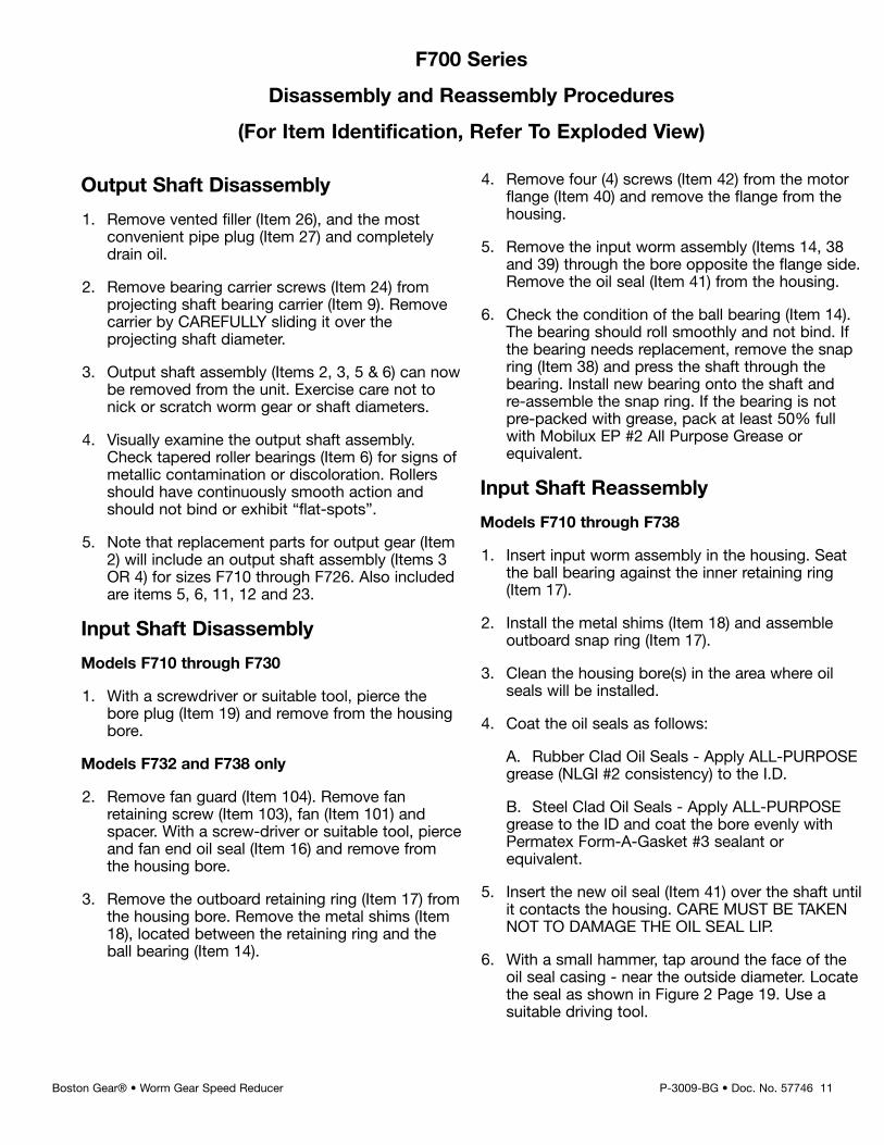
F700 Series
Disassembly and Reassembly Procedures
(For Item Identification, Refer To Exploded View)
Model F710 through F730
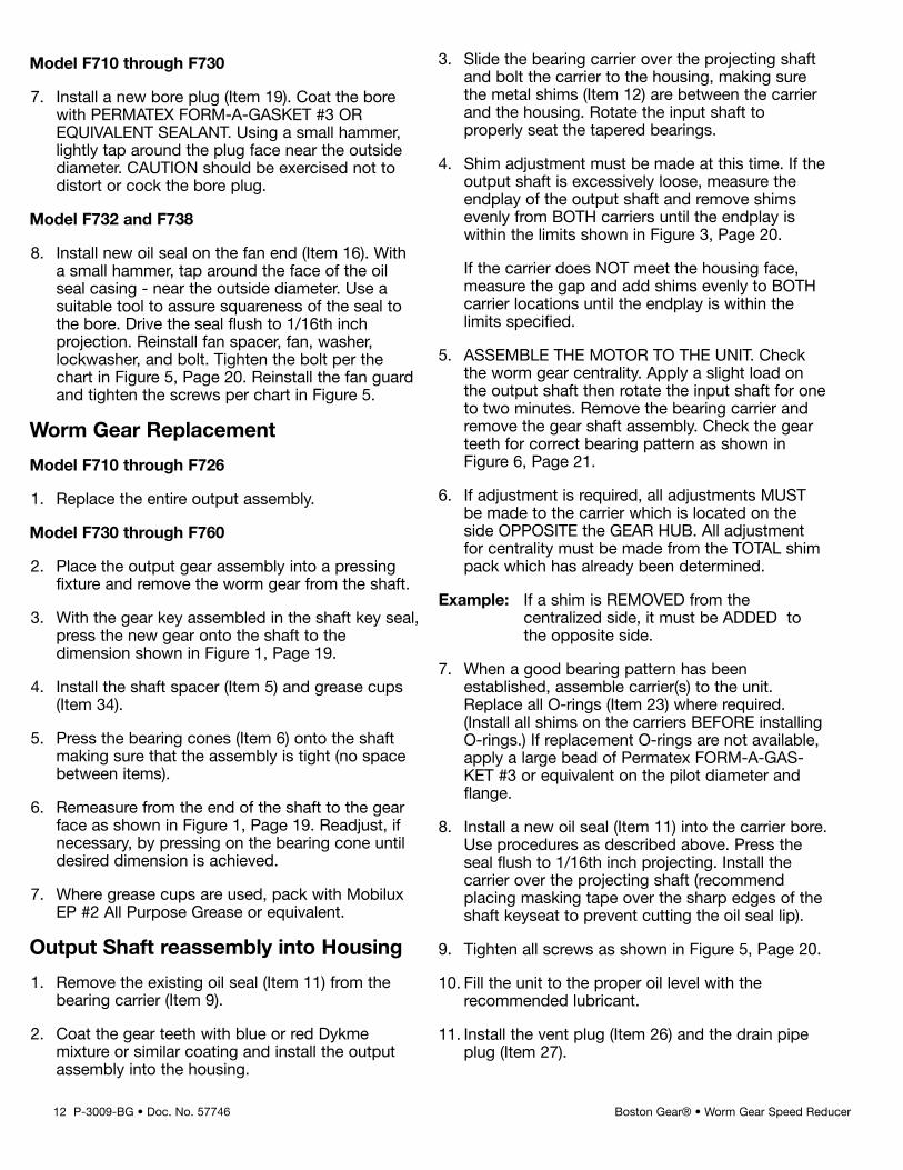
7. Install a new bore plug (Item 19). Coat the borewith PERMATEX FORM-A-GASKET #3 OREQUIVALENT SEALANT. Using a small hammer,lightly tap around the plug face near the outsidediameter. CAUTION should be exercised not todistort or cock the bore plug.
Model F732 and F738
8. Install new oil seal on the fan end (Item 16). Witha small hammer, tap around the face of the oilseal casing - near the outside diameter. Use asuitable tool to assure squareness of the seal tothe bore. Drive the seal flush to 1/16th inchprojection. Reinstall fan spacer, fan, washer,lockwasher, and bolt. Tighten the bolt per thechart in Figure 5, Page 20. Reinstall the fan guardand tighten the screws per chart in Figure 5.
Worm Gear Replacement
Model F710 through F726
1. Replace the entire output assembly.
Model F730 through F760
2. Place the output gear assembly into a pressingfixture and remove the worm gear from the shaft.
3. With the gear key assembled in the shaft key seal,press the new gear onto the shaft to thedimension shown in Figure 1, Page 19.
4. Install the shaft spacer (Item 5) and grease cups(Item 34).
5. Press the bearing cones (Item 6) onto the shaftmaking sure that the assembly is tight (no spacebetween items).
6. Remeasure from the end of the shaft to the gearface as shown in Figure 1, Page 19. Readjust, ifnecessary, by pressing on the bearing cone untildesired dimension is achieved.
7. Where grease cups are used, pack with MobiluxEP #2 All Purpose Grease or equivalent.
Output Shaft reassembly into Housing
1. Remove the existing oil seal (Item 11) from thebearing carrier (Item 9).
2. Coat the gear teeth with blue or red Dykmemixture or similar coating and install the outputassembly into the housing.
3. Slide the bearing carrier over the projecting shaftand bolt the carrier to the housing, making surethe metal shims (Item 12) are between the carrierand the housing. Rotate the input shaft toproperly seat the tapered bearings.
4. Shim adjustment must be made at this time. If theoutput shaft is excessively loose, measure theendplay of the output shaft and remove shimsevenly from BOTH carriers until the endplay iswithin the limits shown in Figure 3, Page 20.
If the carrier does NOT meet the housing face,measure the gap and add shims evenly to BOTHcarrier locations until the endplay is within thelimits specified.
5. ASSEMBLE THE MOTOR TO THE UNIT. Checkthe worm gear centrality. Apply a slight load onthe output shaft then rotate the input shaft for oneto two minutes. Remove the bearing carrier andremove the gear shaft assembly. Check the gearteeth for correct bearing pattern as shown inFigure 6, Page 21.
6. If adjustment is required, all adjustments MUSTbe made to the carrier which is located on theside OPPOSITE the GEAR HUB. All adjustmentfor centrality must be made from the TOTAL shimpack which has already been determined.
Example: If a shim is REMOVED from thecentralized side, it must be ADDED tothe opposite side.
7. When a good bearing pattern has beenestablished, assemble carrier(s) to the unit.Replace all O-rings (Item 23) where required.(Install all shims on the carriers BEFORE installingO-rings.) If replacement O-rings are not available,apply a large bead of Permatex FORM-A-GAS-KET #3 or equivalent on the pilot diameter andflange.
8. Install a new oil seal (Item 11) into the carrier bore.Use procedures as described above. Press theseal flush to 1/16th inch projecting. Install thecarrier over the projecting shaft (recommendplacing masking tape over the sharp edges of theshaft keyseat to prevent cutting the oil seal lip).
9. Tighten all screws as shown in Figure 5, Page 20.
10. Fill the unit to the proper oil level with therecommended lubricant.
11. Install the vent plug (Item 26) and the drain pipeplug (Item 27).
12 P-3009-BG • Doc. No. 57746 Boston Gear® • Worm Gear Speed Reducer
P-3009-BG • Doc. No. 57746 13Boston Gear® • Worm Gear Speed Reducer
Output Shaft Disassembly
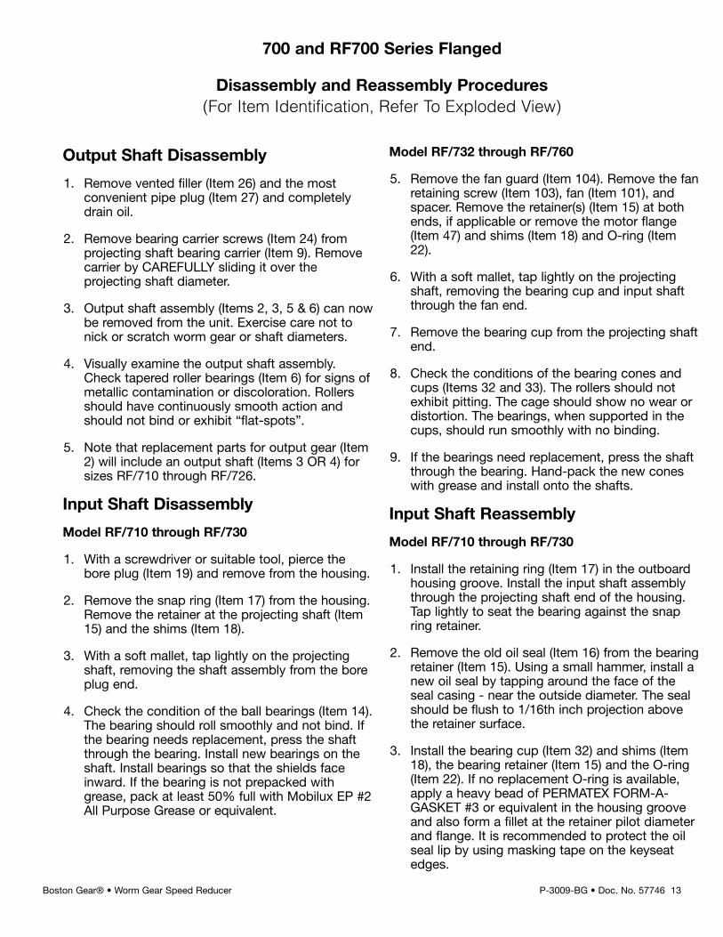
1. Remove vented filler (Item 26) and the mostconvenient pipe plug (Item 27) and completelydrain oil.
2. Remove bearing carrier screws (Item 24) fromprojecting shaft bearing carrier (Item 9). Removecarrier by CAREFULLY sliding it over theprojecting shaft diameter.
3. Output shaft assembly (Items 2, 3, 5 & 6) can nowbe removed from the unit. Exercise care not tonick or scratch worm gear or shaft diameters.
4. Visually examine the output shaft assembly.Check tapered roller bearings (Item 6) for signs ofmetallic contamination or discoloration. Rollersshould have continuously smooth action andshould not bind or exhibit “flat-spots”.
5. Note that replacement parts for output gear (Item2) will include an output shaft (Items 3 OR 4) forsizes RF/710 through RF/726.
Input Shaft Disassembly
Model RF/710 through RF/730
1. With a screwdriver or suitable tool, pierce thebore plug (Item 19) and remove from the housing.
2. Remove the snap ring (Item 17) from the housing.Remove the retainer at the projecting shaft (Item15) and the shims (Item 18).
3. With a soft mallet, tap lightly on the projectingshaft, removing the shaft assembly from the boreplug end.
4. Check the condition of the ball bearings (Item 14).The bearing should roll smoothly and not bind. Ifthe bearing needs replacement, press the shaftthrough the bearing. Install new bearings on theshaft. Install bearings so that the shields faceinward. If the bearing is not prepacked withgrease, pack at least 50% full with Mobilux EP #2All Purpose Grease or equivalent.
Model RF/732 through RF/760
5. Remove the fan guard (Item 104). Remove the fanretaining screw (Item 103), fan (Item 101), andspacer. Remove the retainer(s) (Item 15) at bothends, if applicable or remove the motor flange(Item 47) and shims (Item 18) and O-ring (Item22).
6. With a soft mallet, tap lightly on the projectingshaft, removing the bearing cup and input shaftthrough the fan end.
7. Remove the bearing cup from the projecting shaftend.
8. Check the conditions of the bearing cones andcups (Items 32 and 33). The rollers should notexhibit pitting. The cage should show no wear ordistortion. The bearings, when supported in thecups, should run smoothly with no binding.
9. If the bearings need replacement, press the shaftthrough the bearing. Hand-pack the new coneswith grease and install onto the shafts.
Input Shaft Reassembly
Model RF/710 through RF/730
1. Install the retaining ring (Item 17) in the outboardhousing groove. Install the input shaft assemblythrough the projecting shaft end of the housing.Tap lightly to seat the bearing against the snapring retainer.
2. Remove the old oil seal (Item 16) from the bearingretainer (Item 15). Using a small hammer, install anew oil seal by tapping around the face of theseal casing - near the outside diameter. The sealshould be flush to 1/16th inch projection abovethe retainer surface.
3. Install the bearing cup (Item 32) and shims (Item18), the bearing retainer (Item 15) and the O-ring(Item 22). If no replacement O-ring is available,apply a heavy bead of PERMATEX FORM-A-GASKET #3 or equivalent in the housing grooveand also form a fillet at the retainer pilot diameterand flange. It is recommended to protect the oilseal lip by using masking tape on the keyseatedges.
700 and RF700 Series Flanged
Disassembly and Reassembly Procedures(For Item Identification, Refer To Exploded View)
Model RF/732 through RF/760
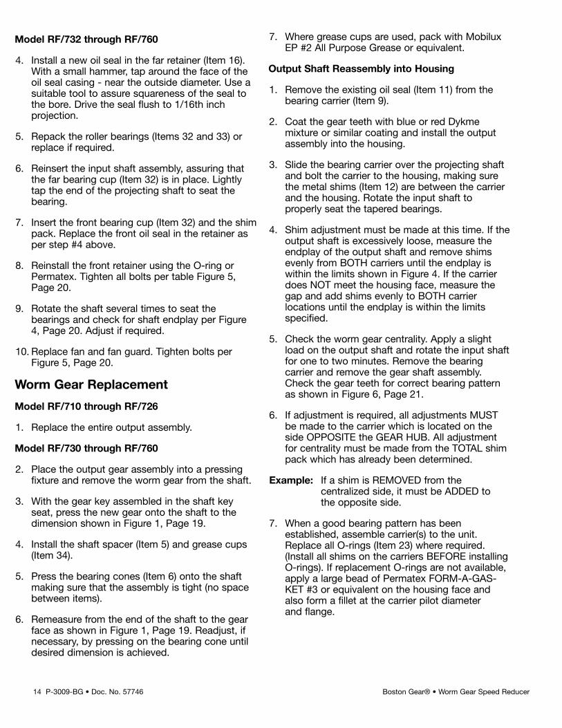
4. Install a new oil seal in the far retainer (Item 16).With a small hammer, tap around the face of theoil seal casing - near the outside diameter. Use asuitable tool to assure squareness of the seal tothe bore. Drive the seal flush to 1/16th inchprojection.
5. Repack the roller bearings (Items 32 and 33) orreplace if required.
6. Reinsert the input shaft assembly, assuring thatthe far bearing cup (Item 32) is in place. Lightlytap the end of the projecting shaft to seat thebearing.
7. Insert the front bearing cup (Item 32) and the shimpack. Replace the front oil seal in the retainer asper step #4 above.
8. Reinstall the front retainer using the O-ring orPermatex. Tighten all bolts per table Figure 5,Page 20.
9. Rotate the shaft several times to seat thebearings and check for shaft endplay per Figure4, Page 20. Adjust if required.
10. Replace fan and fan guard. Tighten bolts perFigure 5, Page 20.
Worm Gear Replacement
Model RF/710 through RF/726
1. Replace the entire output assembly.
Model RF/730 through RF/760
2. Place the output gear assembly into a pressingfixture and remove the worm gear from the shaft.
3. With the gear key assembled in the shaft keyseat, press the new gear onto the shaft to thedimension shown in Figure 1, Page 19.
4. Install the shaft spacer (Item 5) and grease cups(Item 34).
5. Press the bearing cones (Item 6) onto the shaftmaking sure that the assembly is tight (no spacebetween items).
6. Remeasure from the end of the shaft to the gearface as shown in Figure 1, Page 19. Readjust, ifnecessary, by pressing on the bearing cone untildesired dimension is achieved.
7. Where grease cups are used, pack with MobiluxEP #2 All Purpose Grease or equivalent.
Output Shaft Reassembly into Housing
1. Remove the existing oil seal (Item 11) from thebearing carrier (Item 9).
2. Coat the gear teeth with blue or red Dykmemixture or similar coating and install the outputassembly into the housing.
3. Slide the bearing carrier over the projecting shaftand bolt the carrier to the housing, making surethe metal shims (Item 12) are between the carrierand the housing. Rotate the input shaft toproperly seat the tapered bearings.
4. Shim adjustment must be made at this time. If theoutput shaft is excessively loose, measure theendplay of the output shaft and remove shimsevenly from BOTH carriers until the endplay iswithin the limits shown in Figure 4. If the carrierdoes NOT meet the housing face, measure thegap and add shims evenly to BOTH carrierlocations until the endplay is within the limitsspecified.
5. Check the worm gear centrality. Apply a slightload on the output shaft and rotate the input shaftfor one to two minutes. Remove the bearingcarrier and remove the gear shaft assembly.Check the gear teeth for correct bearing patternas shown in Figure 6, Page 21.
6. If adjustment is required, all adjustments MUSTbe made to the carrier which is located on theside OPPOSITE the GEAR HUB. All adjustmentfor centrality must be made from the TOTAL shimpack which has already been determined.
Example: If a shim is REMOVED from thecentralized side, it must be ADDED tothe opposite side.
7. When a good bearing pattern has beenestablished, assemble carrier(s) to the unit.Replace all O-rings (Item 23) where required.(Install all shims on the carriers BEFORE installingO-rings). If replacement O-rings are not available,apply a large bead of Permatex FORM-A-GAS-KET #3 or equivalent on the housing face andalso form a fillet at the carrier pilot diameterand flange.
14 P-3009-BG • Doc. No. 57746 Boston Gear® • Worm Gear Speed Reducer
P-3009-BG • Doc. No. 57746 15Boston Gear® • Worm Gear Speed Reducer
8. Install a new oil seal (Item 11) into the carrier bore.Use procedures as described above. Press theseal flush to 1/16th inch projecting. Install thecarrier over the projecting shaft (recommendplacing masking tape over the sharp edges of theshaft keyseat to prevent cutting the oil seal lip).
9. Tighten all screws as shown in Figure 5, Page 20.
10. Fill the unit to the proper oil level with therecommended lubricant.
11. Install the vent plug (Item 26) and the drain pipeplug (Item 27).
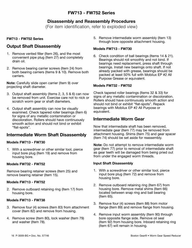
FW713 - FW752 Series
Output Shaft Disassembly
1. Remove vented filler (Item 26), and the mostconvenient pipe plug (Item 27) and completelydrain oil.
2. Remove bearing carrier screws (Item 24) fromboth bearing carriers (Items 9 & 10). Remove bothcarriers.
Note: Carefully slide open carrier (Item 9) overprojecting shaft diameter.
3. Output shaft assembly (Items 2, 3, 5 & 6) can nowbe removed from unit. Exercise care not to nick orscratch worm gear or shaft diameters.
4. Output shaft assembly can now be visuallyexamined. Check tapered roller bearings (Item 6)for signs of any metallic contamination ordiscoloration. Rollers should have continuouslysmooth action and should not bind or exhibit“flat-spots”.
Intermediate Worm Shaft Disassembly
Models FW713 - FW730
1. With a screwdriver or other similar tool, pierceinput bore plug (Item 19) and remove fromhousing bore.
Models FW732 - FW752
Remove bearing retainer screws (Item 25) andremove bearing retainer (Item 15).
Models FW713 - FW752
2. Remove outboard retaining ring (Item 17) fromhousing bore.
Models FW713 - FW738
3. Remove four (4) screws (Item 83) from attachmentcover (Item 82) and remove from housing.
4. Remove screw (Item 80), lock washer (Item 79)and washer (Item 78).
5. Remove intermediate worm assembly (Item 13)through bore opposite attachment housing.
Models FW713 - FW730
6. Check condition of ball bearings (Items 14 & 21).Bearings should roll smoothly and not bind. Ifbearings need replacement, press shaft throughbearings. Install new bearings onto shaft. If notalready packed with grease, bearings should bepacked at least 50% full with Mobilux EP #2 AllPurpose Grease or equivalent.
Models FW732 - FW752
Check tapered roller bearings (Items 32 & 33) forsigns of any metallic contamination or discoloration.Rollers should have continuously smooth action andshould not bind or exhibit “flat-spots”. Repackbearings with Mobilux EP #2 All Purpose orequivalent.
Intermediate Worm Gear
Now that intermediate shaft has been removed,intermediate gear (Item 77) may be removed fromattachment housing. Shims (Item 75) and gear spacer(Item 74) should be set aside for reassembly.
Note: Do not attempt to remove intermediate wormgear (Item 77) prior to removal of intermediate shaftas gear teeth will be damaged from being pried outfrom under the engaged worm threads.
Input Shaft Disassembly
1. With a screwdriver or other similar tool, pierceinput bore plug (Item 72) and remove fromhousing bore.
2. Remove outboard retaining ring (Item 67) fromhousing bore. Remove metal shims (Item 66)located between snap ring and ball bearing(Item 65).
3. Remove four (4) screws (Item 88) from motorflange (Item 89) and remove flange from housing.
4. Remove input worm assembly (Item 90) throughbore opposite flange side. Remove oil seal(Item 92) from housing bore. Inboard retaining ring(Item 67) will remain in housing.
16 P-3009-BG • Doc. No. 57746 Boston Gear® • Worm Gear Speed Reducer
FW713 - FW752 Series
Disassembly and Reassembly Procedures(For item identification, refer to exploded view)
P-3009-BG • Doc. No. 57746 17Boston Gear® • Worm Gear Speed Reducer
5. Check condition of ball bearing (Item 65). Bearingshould roll smoothly and not bind. If bearingsneed replacement, remove snap ring (Item 91)and press shaft through bearing.
Install new bearing onto shaft and reassemble snapring (Item 91). If not already packed with grease,bearing should be packed at least 50% full withMobilux EP #2 All Purpose Grease or equivalent.
Input Shaft Reassembly
1. Insert input worm shaft assembly (Item 90) intohousing with retaining ring (Item 67) used to seatball bearing.
2. Install metal shims (Item 66) and assembleoutboard snap ring (Item 67).
3. Clean housing bore(s) in area where oil seal is tobe inserted.
4. Oil Seal Assembly:
A. Rubber Clad Oil Seal
Apply All Purpose Grease (NLGI #2consistency) to I.D. and O.D.
B. Steel Clad Oil seal
Lightly apply All Purpose Grease to I.D. onlyand coat bore evenly with Permatex “AviationFORM-A-GASKET” #3 or equivalent.
5. Insert new oil seal (Item 92) over the shaft (caremust be taken not to damage oil seal lip) until itcontacts the housing.
6. With small hammer, tap around the face of sealcasing near the outside diameter. Oil seal locationas follows:
Flange end oil seal - Refer to Figure (2) Page 19(use suitable driving tool to recess seal).
7. Install new bore plug (Item 72). Coat bore withPERMATEX “Aviation FORM-A-GASKET” #3 orequivalent sealant. If rubber clan O.D. no sealantis required. Using small hammer, lightly taparound plug face near the outside diameter.Caution should be exercised not to distort or cockplug during installation.
8. Assemble motor flange (Item 89).
Intermediate Worm Reassembly
1. Insert intermediate worm assembly (Item 13)through bore opposite attachment housing.
Note: Spacer (Item 74) and shims (Item 75) should beput on shaft and worm gear (Item 77) held inmesh with input worm (Item 90) while slidingintermediate worm assembly into position.
2. Assemble attachment cover (Item 82).
Models FW713 - FW730
3. Install new bore plug (Item 19). Coat bore withPERMATEX “Aviation FORM-A-GASKET” #3 orequivalent sealant. If rubber clad O.D. no sealantis required. Using small hammer, lightly taparound plug face near the outside diameter.Caution should be exercised not to distort orcock plug during installation.
Models FW732 - FW752
Assemble intermediate bearing retainer (Item 15).
Worm Gear Replacement
Models FW713 - FW726
1. Replace entire output assembly.
Models FW730 - FW752
1. Place output gear assembly (Item 2) into apressing fixture and remove worm gear fromshaft.
2. With gear key assembled in shaft keyseat, pressnew gear onto shaft to dimension shown in Figure1, Page 19.
3. Install shaft spacer (Item 5) and grease cups (Item34) when applicable.
4. Press bearing cones (Item 6) onto shaft makingsure the assembly is tight.
5. Remeasure from end of shaft to worm gear faceas shown in Figure 1, Page 19. If adjustment isnecessary, press bearing cone (Item 6) untilrequired dimension is achieved.
6. Where grease cups are used, pack with MobilusEP #2 All Purpose Grease or equivalent.
Output Shaft Reassembly into Housing
1. Remove existing oil seal (Item 11) from bearingcarrier (Item 9).
2. Coat gear teeth (Item 3) with red-lead mixture orsimilar coating and install output gear assemblyinto housing.
3. Slide bearing carrier (Item 9) over projecting shaft(Item 4) diameter and bolt carrier to housing.Make sure metal shims (Item 12) are betweencarrier and housing face. Rotate input shaft toproperly seat tapered roller bearings.
4. Adjustments of shims (Item 12) must be made atthis time. If output shaft is excessively loose,measure endplay of output shaft and removeshims (Item 12) evenly from both carriers (Items 9and 10) until endplay is within limits specified onFigures 3 or 4, Page 20.
If bearing carrier (Item 9) does not meet housingface, measure gap and add shims (Item 12)evenly to each side (Items 9 and 10).
5. Assemble motor to unit. Check worm gearcentrality. Apply slight load to output shaft androtate input shaft for 1 or 2 minutes. Removeoutput bearing carrier (Item 9) and remove outputgear assembly. Check gear teeth for bearingpattern. Optimum bearing pattern is shown inFigure 3, Page 20.
If gear requires adjustment for centrality, alladjustments must be made from side oppositegear hub.
Note: All adjustment for gear centrality to be madefrom the already established total shim pack(Ref. - Step 4). For example - If a shim isremoved from centralized side, it must beadded to the opposite side.
6. When good bearing pattern or gear teeth isestablished, assemble carriers(s) to unit. ApplyPERMATEX “Aviation FORM-A-GASKET” #3 orequivalent sealant to form fillet at pilot diameter ofcarrier. Install new oil seal (Item 12) into bearingcarrier bore. Seal assembly same as shown in“Input Shaft Reassembly” - Steps 4, 5 and 6.(Recommend masking tape over sharp keyseatedges so seal lip is not cut or damaged.) Oil sealto be flush with carrier face.
7. Fill unit to proper level with recommended gearlubrication. (Ref. Page 5.)
8. Install vent (Item 26) and pipe plug (Item 27).
Important: All screw tightening torques listed inFigure 5, Page 20.
Note: For RFW and W700 Series Ref. to SingleReduction Instructions for 700/RF Series InputDisassembly and reassembly Page 13.
18 P-3009-BG • Doc. No. 57746 Boston Gear® • Worm Gear Speed Reducer
P-3009-BG • Doc. No. 57746 19Boston Gear® • Worm Gear Speed Reducer
B
A
BOSTON
C
Unit “C”Size Dimension
F710/FW713 5/16FW718
F713/FW721 3/8FW726
F715 3/8F718/FW732 3/8F721/FW738 3/8F724 3/8F726 3/8F730 3/8F732 5/8F738 5/8
Unit “A” ± 1/64 “B” Ref. Only730 6.310 6-3/4732 7.469 7-1/16738 7.25 7-3/4752 8.44 9-1/16760 9.28 10
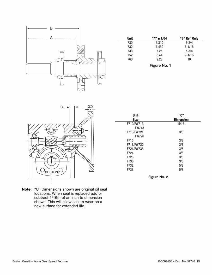
Figure No. 1
Figure No. 2
Note: “C” Dimensions shown are original oil seallocations. When seal is replaced add orsubtract 1/16th of an inch to dimensionshown. This will allow seal to wear on anew surface for extended life.
20 P-3009-BG • Doc. No. 57746 Boston Gear® • Worm Gear Speed Reducer
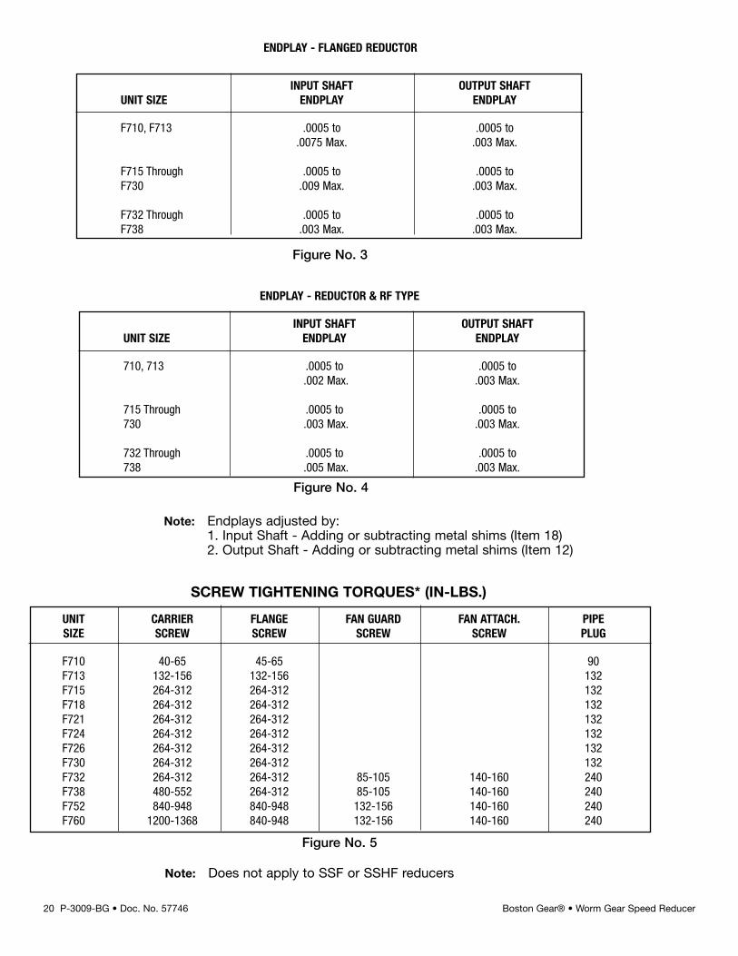
UNIT CARRIER FLANGE FAN GUARD FAN ATTACH. PIPESIZE SCREW SCREW SCREW SCREW PLUG
F710 40-65 45-65 90F713 132-156 132-156 132F715 264-312 264-312 132F718 264-312 264-312 132F721 264-312 264-312 132F724 264-312 264-312 132F726 264-312 264-312 132F730 264-312 264-312 132F732 264-312 264-312 85-105 140-160 240F738 480-552 264-312 85-105 140-160 240F752 840-948 840-948 132-156 140-160 240F760 1200-1368 840-948 132-156 140-160 240
ENDPLAY - FLANGED REDUCTOR
ENDPLAY - REDUCTOR & RF TYPE
SCREW TIGHTENING TORQUES* (IN-LBS.)
INPUT SHAFT OUTPUT SHAFTUNIT SIZE ENDPLAY ENDPLAY
F710, F713 .0005 to .0005 to.0075 Max. .003 Max.
F715 Through .0005 to .0005 toF730 .009 Max. .003 Max.
F732 Through .0005 to .0005 toF738 .003 Max. .003 Max.
INPUT SHAFT OUTPUT SHAFTUNIT SIZE ENDPLAY ENDPLAY
710, 713 .0005 to .0005 to.002 Max. .003 Max.
715 Through .0005 to .0005 to730 .003 Max. .003 Max.
732 Through .0005 to .0005 to738 .005 Max. .003 Max.
Figure No. 3
Figure No. 4
Figure No. 5
Note: Endplays adjusted by:1. Input Shaft - Adding or subtracting metal shims (Item 18)2. Output Shaft - Adding or subtracting metal shims (Item 12)
Note: Does not apply to SSF or SSHF reducers
P-3009-BG • Doc. No. 57746 21Boston Gear® • Worm Gear Speed Reducer
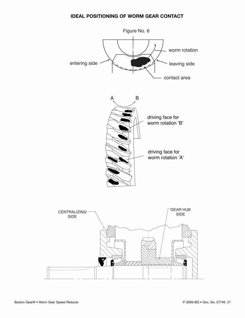
Figure No. 6
worm rotation
leaving side
contact area
entering side
A B
driving face forworm rotation ’A’
driving face forworm rotation ’B’
GEAR HUBSIDECENTRALIZING
SIDE
IDEAL POSITIONING OF WORM GEAR CONTACT
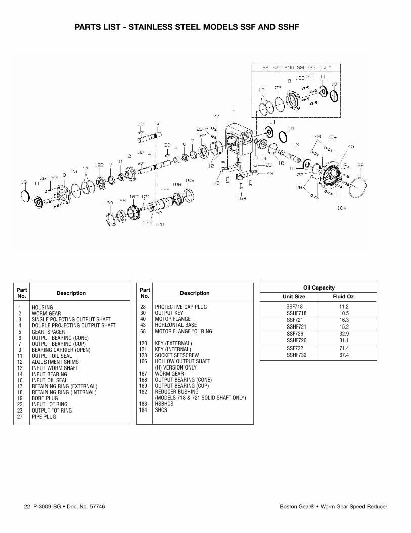
Oil Capacity
Unit Size Fluid Oz.
SSF718 11.2SSHF718 10.5SSF721 16.3SSHF721 15.2SSF726 32.9SSHF726 31.1SSF732 71.4SSHF732 67.4
1 HOUSING2 WORM GEAR3 SINGLE POJECTING OUTPUT SHAFT4 DOUBLE PROJECTING OUTPUT SHAFT5 GEAR SPACER6 OUTPUT BEARING (CONE)7 OUTPUT BEARING (CUP)9 BEARING CARRIER (OPEN)11 OUTPUT OIL SEAL12 ADJUSTMENT SHIMS13 INPUT WORM SHAFT14 INPUT BEARING16 INPUT OIL SEAL17 RETAINING RING (EXTERNAL)18 RETAINING RING (INTERNAL)19 BORE PLUG22 INPUT “O” RING23 OUTPUT “O” RING27 PIPE PLUG
28 PROTECTIVE CAP PLUG30 OUTPUT KEY40 MOTOR FLANGE43 HORIZONTAL BASE68 MOTOR FLANGE “O” RING
120 KEY (EXTERNAL)121 KEY (INTERNAL)123 SOCKET SETSCREW166 HOLLOW OUTPUT SHAFT
(H) VERSION ONLY167 WORM GEAR168 OUTPUT BEARING (CONE)169 OUTPUT BEARING (CUP)182 REDUCER BUSHING
(MODELS 718 & 721 SOLID SHAFT ONLY)183 HSBHCS184 SHCS
Part DescriptionNo.
22 P-3009-BG • Doc. No. 57746 Boston Gear® • Worm Gear Speed Reducer
PARTS LIST - STAINLESS STEEL MODELS SSF AND SSHF
Part DescriptionNo.
P-3009-BG • Doc. No. 57746 23Boston Gear® • Worm Gear Speed Reducer
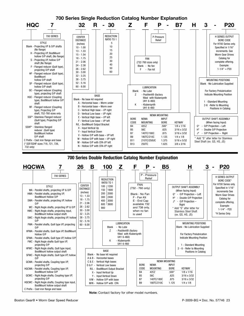
HQCWA 7 26 B 100 Z F P - B5 H 3 - P20
MOUNTING POSITIONSBlank - No Lubrication Supplied
For Factory PrelubricationIndicate Mounting Position
1 - Standard Mounting2 - 6 - Refer to Mounting
Positions in Catalog
LUBRICATIONBlank - No LubeZ - PosiVent® (factory
filled with KlubersynthUH1 6-460)
K - KlubersynthUH1 6-460
LUBRICATIONBlank - No LubeZ - PosiVent® (factory
filled with KlubersynthUH1 6-460)
K - KlubersynthUH1 6-460
OUTPUT SHAFT ASSEMBLY(When facing Input)
G* - O/P Projection – LeftH* - Double O/P ProjectionJ* - O/P Projection –
Right* Add “S” after letter forStainless Steel Shaft(ex. GS, HS, JS)
REDUCTIONRATIO TO 1100 1200150 1800200 2000300 2400400 3000600 3600900
700 SERIES
NEMA MOUNTINGBORE NEMA INPUTCODE MOUNTING BORE KEYWAYB4 42CZ .500" 1/8 x 1/16B5 56C .625 3/16 x 3/32B7 140TC/180C .875 3/16 x 3/32B9 180TC/210C 1.125 1/4 x 1/8
Note: Contact factory for other model numbers.
H SERIES OUTPUTBORE CODE*
For H700 Series only.Specified in 1/16"increments See
Worm Gear DrivesCatalog for
complete offering.Example:
1-1/4" - P20
*H Series Only
BASEBlank - No base kit requiredA & B - Horizontal basesC & E - Vertical High basesD & F - Vertical Low bases
R/L - BostMount Output BracketX - Input Vertical UpY - Input Vertical Down
V/W - Hollow O/P with baseM/N - Hollow O/P with CFA
CENTERDISTANCE(inches)13 - 1.3318 - 1.7521 - 2.0626 - 2.6230 - 3.0032 - 3.2538 - 3.7552 - 5.1660 - 6.00
HQC 7 32 R - 30 Z F P - B7 H 3 - P20
MOUNTING POSITIONSBlank -No Lubrication Supplied
For Factory PrelubricationIndicate Mounting Position
1 -Standard Mounting2-6 -Refer to Mounting
Positions in Catalog
FAN(732-760 sizes only)Blank - No fanF - Fan kit
OUTPUT SHAFT ASSEMBLY(When facing Input)
G* - O/P Projection – LeftH* - Double O/P ProjectionJ* - O/P Projection – Right
REDUCTIONRATIO TO 1
51015202530405060
CENTERDISTANCE(inches)10 - 1.0013 - 1.3315 - 1.5418 - 1.7521 - 2.0624 - 2.3826 - 2.6230 - 3.0032 - 3.2538 - 3.7552 - 5.1660 - 6.00
700 SERIES
STYLEBlank - Projecting I/P & O/P shafts
(No flange)H - Projecting I/P, BostMount
hollow O/P shaft, (No flange)S - Projecting I/P, hollow O/P
shaft (No flange)F - Flanged reducer (Quill type),
projecting O/P shaftHF - Flanged reducer (Quill type),
BostMounthollow O/P shaft
SF - Flanged reducer (Quill type),hollow O/P shaft
QC - Flanged reducer (Couplingtype), projecting O/P shaft
HQC - Flanged reducer (Couplingtype), BostMount hollow O/Pshaft
RF - Flanged reducer (Couplingtype), Projecting O/Pshaft, 752-760 sizes only
SSF*- Stainless Flanged reducer(Quill type), Projecting O/Pshaft
SSHF* - Stainless flangedreducer (Quill type)BostMount hollowO/P shaft
C Prefix - Cast iron flange and base(* SSF/SSHF sizes 718, 721, 726,732 only)
NEMA MOUNTINGBORE NEMA INPUTCODE MOUNTING BORE KEYWAYB4 42CZ .500" 1/8 x 1/16B5 56C .625 3/16 x 3/32B7 140TC/180C .875 3/16 x 3/32B9 180TC/210C 1.125 1/4 x 1/8B11 210TC/250UC 1.375 5/16 x 5/32B13 250TC 1.625 3/8 x 3/16
H SERIES OUTPUTBORE CODE
For H700 Series only.Specified in 1/16"increments. SeeWorm Gear Drives
Catalog forcomplete offering.
Example:1-1/4" = P20
BASEBlank - No base kit required
A - Horizontal base – Worm underB - Horizontal base – Worm overC - Vertical High base – I/P rightD - Vertical Low base – I/P rightE - Vertical High base – I/P leftF - Vertical Low base – I/P left
R/L - BostMount Output BracketX - Input Vertical UpY - Input Vertical DownV - Hollow O/P with base – I/P leftW - Hollow O/P with base – I/P rightM - Hollow O/P with CFA-I/P leftN - Hollow O/P with CFA-I/P right
STYLEWA - Parallel shafts, projecting I/P & O/P
HWA - Parallel shafts, projecting I/P,BostMount Hollow O/P
SWA - Parallel shafts, projecting I/P, hollowO/P
WC - Right Angle shafts, projecting I/P & O/PHWC - Right Angle shafts, projecting input,
BostMount hollow output shaft.SWC - Right Angle shafts, projecting I/P, hollow
O/PFWA - Parallel shafts, Quill type I/P, projecting
O/PHFWA - Parallel shafts, Quill type I/P, BostMount
Hollow O/PSFWA - Parallel shafts, Quill type I/P, hollow O/PFWC - Right Angle shafts Quill type I/P,
projecting O/PHFWC - Right Angle shafts, Quill type input,
BostMount hollow output shaftSFWC - Right Angle shafts, Quill type I/P, hollow
O/PQCWA - Parallel shafts, Coupling type I/P,
projecting O/PHQCWA - Parallel shafts, Coupling type I/P,
BostMount hollow O/PQCWC - Right Angle shafts, Coupling type I/P,
projecting O/PHQCWC - Right Angle shafts, Coupling type input,
BostMount hollow output shaftC Prefix - Cast iron flange and base
700 Series Double Reduction Catalog Number Explanation
700 Series Single Reduction Catalog Number Explanation
P-PressureRelief
FAN(732 - 760 only)
Blank - No FanF - Fan KitE - End Capavailable 732and 738 only,when no fanis used
P - PressureRelief
* Add “S” after letter for StainlessSteel Shaft (ex. GS, HS, JS)
P-3009-BG • Doc. No. 57746 • 10/07 Printed in U.S.A
Warranty
Boston Gear14 Hayward Street, Quincy, MA 02171617.328.3300 fax 617.479.623www.bostongear.comAn Altra Industrial Motion Company
The Company warrants that all 700 Series speed reducers will be free from defects in material andworkmanship over the lifetime of the product.
Oil seals are considered to be replaceable maintenance items.
Any products which shall be proved to the Company’s satisfaction to have been defective at the time ofdelivery in these respects will be replaced or repaired by the Company at its option. Freight is theresponsibility of the customer. The Company’s liability under this warranty is limited to such replacementor repair and it shall not be held liable in any form of action for direct or consequential damages toproperty or person. THE FOREGOING WARRANTY IS EXPRESSLY MADE IN LIEU OF ALL OTHERWARRANTIES WHATSOEVER, EXPRESS, IMPLIED AND STATUTORY AND INCLUDING WITHOUTLIMITATION THE IMPLIED WARRANTIES OF MERCHANTABILITY AND FITNESS. No employee, agent,distributor, or other person is authorized to give additional warranties on behalf of Boston Gear, nor toassume for Boston Gear any other liability in connection with any of its products, except an officer ofBoston Gear by a signed writing.
LUBRICATIONBlank - No LubeK - Klubersynth
UH1 6-460
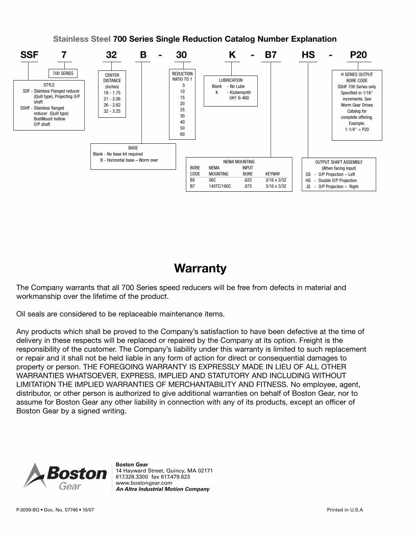
SSF 7 32 B - 30 K - B7 HS - P20
OUTPUT SHAFT ASSEMBLY(When facing Input)
GS - O/P Projection – LeftHS - Double O/P ProjectionJS - O/P Projection – Right
REDUCTIONRATIO TO 1
51015202530405060
CENTERDISTANCE(inches)18 - 1.7521 - 2.0626 - 2.6232 - 3.25
700 SERIES
STYLESSF - Stainless Flanged reducer
(Quill type), Projecting O/Pshaft
SSHF - Stainless flangedreducer (Quill type)BostMount hollowO/P shaft
NEMA MOUNTINGBORE NEMA INPUTCODE MOUNTING BORE KEYWAYB5 56C .625 3/16 x 3/32B7 140TC/180C .875 3/16 x 3/32
H SERIES OUTPUTBORE CODE
SSHF 700 Series only.Specified in 1/16"increments. SeeWorm Gear Drives
Catalog forcomplete offering.
Example:1-1/4" = P20
BASEBlank - No base kit required
B - Horizontal base – Worm over
Stainless Steel 700 Series Single Reduction Catalog Number Explanation