Masterpact NT/NW Compact NS630b-3200origin-faq.pro-face.com/resources/sites/PROFACE... ·...
12
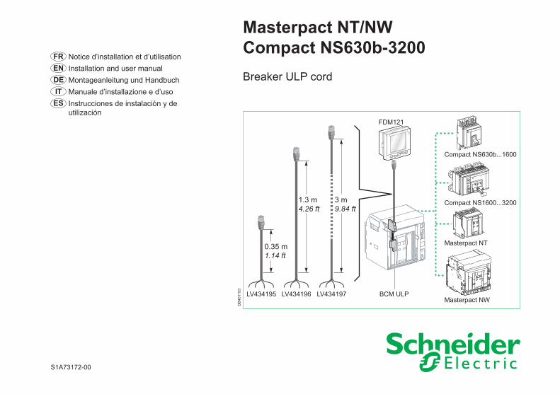
Masterpact NT/NW Compact NS630b-3200 Breaker ULP cord FR Notice d’installation et d’utilisation EN Installation and user manual DE Montageanleitung und Handbuch IT Manuale d’installazione e d’uso ES Instrucciones de instalación y de utilización S1A73172-00 Masterpact NT Masterpact NW Compact NS1600...3200 FDM121 Compact NS630b...1600 0.35 m 1.14 ft 1.3 m 4.26 ft 3 m 9.84 ft LV434195 LV434196 LV434197 BCM ULP DB401153
Transcript of Masterpact NT/NW Compact NS630b-3200origin-faq.pro-face.com/resources/sites/PROFACE... ·...
Masterpact NT/NW Compact NS630b-3200 Breaker ULP cord
FR Notice d’installation et d’utilisation EN Installation and user manual DE Montageanleitung und HandbuchIT Manuale d’installazione e d’usoES Instrucciones de instalación y de
utilización
S1A73172-00
Masterpact NT
Masterpact NW
Compact NS1600...3200
FDM121
Compact NS630b...1600
0.35 m1.14 ft
1.3 m4.26 ft
3 m9.84 ft
LV434195 LV434196 LV434197 BCM ULP
DB
4011
53
2/12S1A73172-00
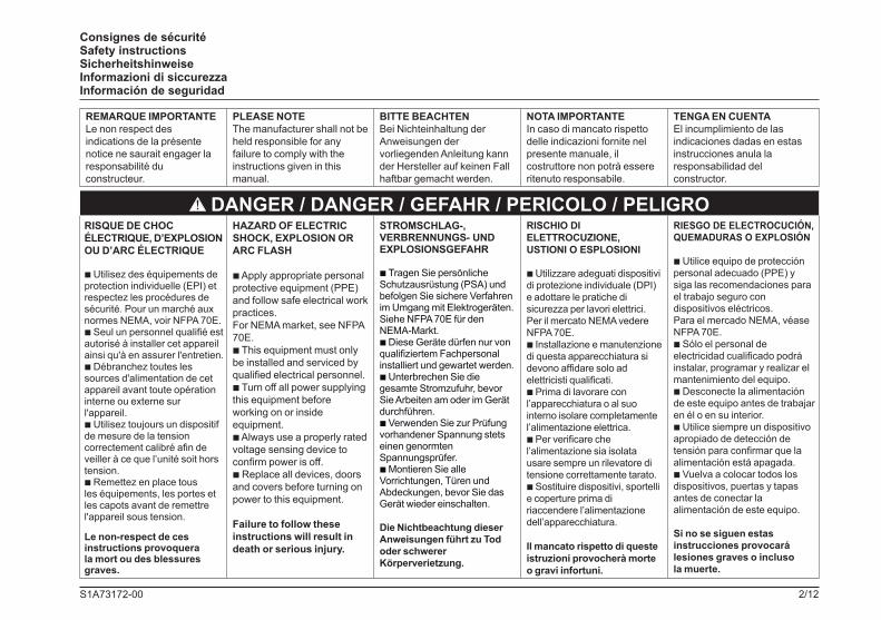
Consignes de sécurité Safety instructions Sicherheitshinweise Informazioni di siccurezza Información de seguridad
REMARQUE IMPORTANTELe non respect des indications de la présente notice ne saurait engager la responsabilité du constructeur.
PLEASE NOTEThe manufacturer shall not be held responsible for any failure to comply with the instructions given in this manual.
BITTE BEACHTENBei Nichteinhaltung derAnweisungen der vorliegenden Anleitung kann der Hersteller auf keinen Fall haftbar gemacht werden.
NOTA IMPORTANTEIn caso di mancato rispettodelle indicazioni fornite nelpresente manuale, ilcostruttore non potrà essere ritenuto responsabile.
TENGA EN CUENTAEl incumplimiento de lasindicaciones dadas en estas instrucciones anula laresponsabilidad delconstructor.
DANGER / DANGER / GEFAHR / PERICOLO / PELIGRORISQUE DE CHOC ÉLECTRIQUE, D’EXPLOSION OU D’ARC ÉLECTRIQUE
b Utilisez des équipements de protection individuelle (EPI) et respectez les procédures de sécurité. Pour un marché aux normes NEMA, voir NFPA 70E.b Seul un personnel qualifié est autorisé à installer cet appareil ainsi qu'à en assurer l'entretien.b Débranchez toutes les sources d'alimentation de cet appareil avant toute opération interne ou externe sur l'appareil.b Utilisez toujours un dispositif de mesure de la tension correctement calibré afin de veiller à ce que l’unité soit hors tension.b Remettez en place tous les équipements, les portes et les capots avant de remettre l'appareil sous tension.
Le non-respect de ces instructions provoquera la mort ou des blessures graves.
HAZARD OF ELECTRIC SHOCK, EXPLOSION OR ARC FLASH
b Apply appropriate personal protective equipment (PPE) and follow safe electrical work practices. For NEMA market, see NFPA 70E.b This equipment must only be installed and serviced by qualified electrical personnel.b Turn off all power supplying this equipment before working on or inside equipment.b Always use a properly rated voltage sensing device to confirm power is off.b Replace all devices, doors and covers before turning on power to this equipment.
Failure to follow these instructions will result in death or serious injury.
STROMSCHLAG-, VERBRENNUNGS- UND EXPLOSIONSGEFAHR
b Tragen Sie persönliche Schutzausrüstung (PSA) und befolgen Sie sichere Verfahren im Umgang mit Elektrogeräten. Siehe NFPA 70E für den NEMA-Markt.b Diese Geräte dürfen nur von qualifiziertem Fachpersonal installiert und gewartet werden.b Unterbrechen Sie die gesamte Stromzufuhr, bevor Sie Arbeiten am oder im Gerät durchführen.b Verwenden Sie zur Prüfung vorhandener Spannung stets einen genormten Spannungsprüfer.b Montieren Sie alle Vorrichtungen, Türen und Abdeckungen, bevor Sie das Gerät wieder einschalten.
Die Nichtbeachtung dieser Anweisungen führt zu Tod oder schwerer Körperverietzung.
RISCHIO DI ELETTROCUZIONE, USTIONI O ESPLOSIONI
b Utilizzare adeguati dispositivi di protezione individuale (DPI) e adottare le pratiche di sicurezza per lavori elettrici.Per il mercato NEMA vedere NFPA 70E.b Installazione e manutenzione di questa apparecchiatura si devono affidare solo ad elettricisti qualificati.b Prima di lavorare con l’apparecchiatura o al suo interno isolare completamente l’alimentazione elettrica. b Per verificare che l’alimentazione sia isolata usare sempre un rilevatore di tensione correttamente tarato.b Sostituire dispositivi, sportelli e coperture prima di riaccendere l’alimentazione dell’apparecchiatura.
Il mancato rispetto di queste istruzioni provocherà morte o gravi infortuni.
RIESGO DE ELECTROCUCIÓN, QUEMADURAS O EXPLOSIÓN
b Utilice equipo de protección personal adecuado (PPE) y siga las recomendaciones para el trabajo seguro con dispositivos eléctricos.Para el mercado NEMA, véase NFPA 70E.b Sólo el personal de electricidad cualificado podrá instalar, programar y realizar el mantenimiento del equipo.b Desconecte la alimentación de este equipo antes de trabajar en él o en su interior.b Utilice siempre un dispositivo apropiado de detección de tensión para confirmar que la alimentación está apagada.b Vuelva a colocar todos los dispositivos, puertas y tapas antes de conectar la alimentación de este equipo.
Si no se siguen estas instrucciones provocará lesiones graves o incluso la muerte.
3/12S1A73172-00
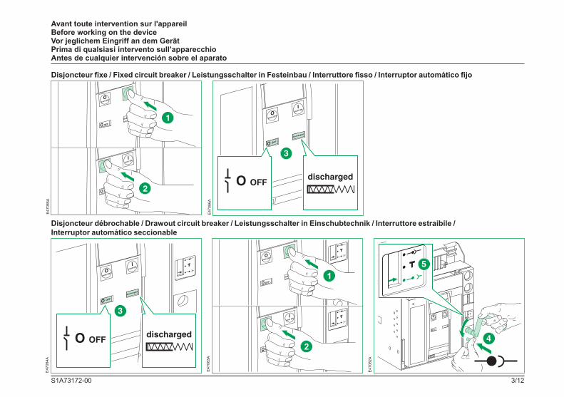
Avant toute intervention sur l'appareil Before working on the device Vor jeglichem Eingriff an dem Gerät Prima di qualsiasi intervento sull’apparecchio Antes de cualquier intervención sobre el aparato
E47
085A
E47
086A
Disjoncteur fixe / Fixed circuit breaker / Leistungsschalter in Festeinbau / Interruttore fisso / Interruptor automático fijo
Disjoncteur débrochable / Drawout circuit breaker / Leistungsschalter in Einschubtechnik / Interruttore estraibile / Interruptor automático seccionable
E47
083A
E47
082A
E47
084A
Ipus h ON
Opus h OF F
O
4/12S1A73172-00
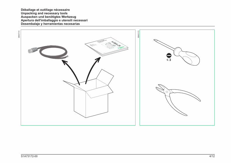
Déballage et outillage nécessaire Unpacking and necessary tools Auspacken und benötigtes Werkzeug Apertura dell'imballaggio e utensili necessari Desembalaje y herramientas necesarias
DB
4011
72
y 3
DB
4011
73
5/12S1A73172-00
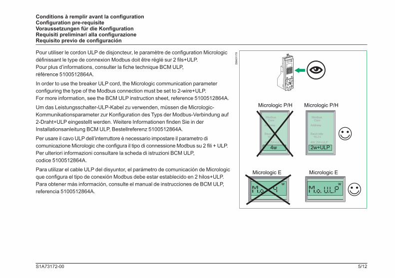
Conditions à remplir avant la configuration Configuration pre-requisite Voraussetzungen für die Konfiguration Requisiti preliminari alla configurazione Requisito previo de configuración
Micrologic P/H
ModbusCom
Address
Baud-rate19.2 k
4W, 2W+ULP
2w+ULP
Micrologic P/H
ModbusCom
Address
Baud-rate19.2 k
4W, 2W+ULP
m enu
100
w
Micrologic E
w
Micrologic E
4w
DB
4011
78Pour utiliser le cordon ULP de disjoncteur, le paramètre de configuration Micrologic définissant le type de connexion Modbus doit être réglé sur 2 fils+ULP. Pour plus d’informations, consulter la fiche technique BCM ULP, référence 5100512864A.
In order to use the breaker ULP cord, the Micrologic communication parameter configuring the type of the Modbus connection must be set to 2-wire+ULP. For more information, see the BCM ULP instruction sheet, reference 5100512864A.
Um das Leistungsschalter-ULP-Kabel zu verwenden, müssen die Micrologic-Kommunikationsparameter zur Konfiguration des Typs der Modbus-Verbindung auf 2-Draht+ULP eingestellt werden. Weitere Informationen finden Sie in der Installationsanleitung BCM ULP, Bestellreferenz 5100512864A.
Per usare il cavo ULP dell’interruttore è necessario impostare il parametro di comunicazione Micrologic che configura il tipo di connessione Modbus su 2 fili + ULP. Per ulteriori informazioni consultare la scheda di istruzioni BCM ULP, codice 5100512864A.
Para utilizar el cable ULP del disyuntor, el parámetro de comunicación de Micrologic que configura el tipo de conexión Modbus debe estar establecido en 2 hilos+ULP. Para obtener más información, consulte el manual de instrucciones de BCM ULP, referencia 5100512864A.
6/12S1A73172-00
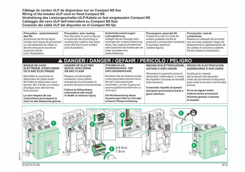
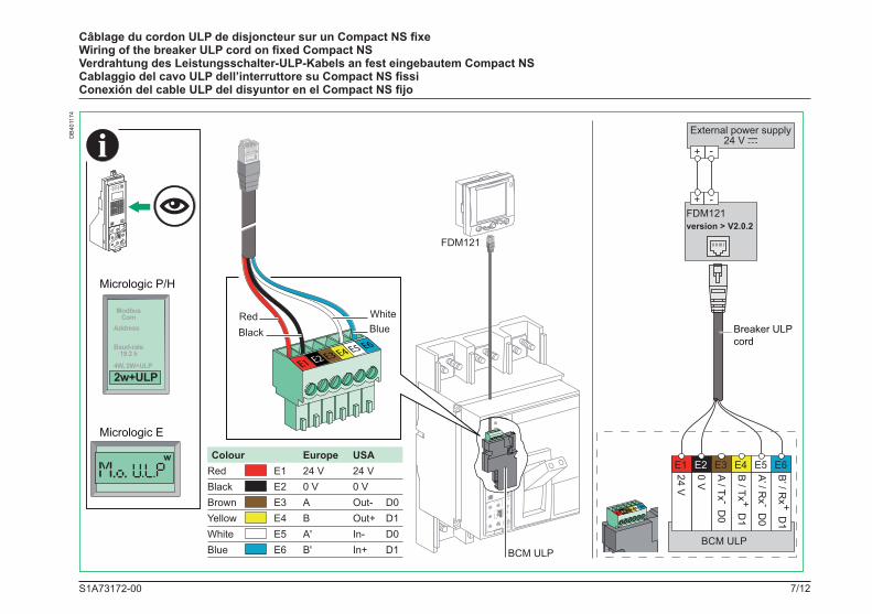
Câblage du cordon ULP de disjoncteur sur un Compact NS fixe Wiring of the breaker ULP cord on fixed Compact NS Verdrahtung des Leistungsschalter-ULP-Kabels an fest eingebautem Compact NS Cablaggio del cavo ULP dell’interruttore su Compact NS fissiConexión del cable ULP del disyuntor en el Compact NS fijo
Précaution : acheminement des filsAcheminez les fils de façon à éviter tout risque de pincement ou d’écrasement du câble ou des fils lorsque le couvercle avant est monté (voir l’illustration).
Precaution: wire routingRun the wires in such a way as to avoid all risk of pinching or crushing the cable or the wires when the front cover is fitted (see illustration).
Sicherheitsvorkehrungen: LeitungsführungVerlegen Sie die Leitungen beim Anbringen der vorderen Abdeckung derart, dass jegliches Einklemmen oder Quetschen des Kabels oder der Leiter vermieden wird (siehe Abbildung).
Precauzioni: posa dei filiPosare fili e cavi in modo da evitare qualsiasi rischio di pizzicarli o schiacciarli montando lo sportello anteriore (vedere figura).
Precaución: ruta de conexionesRealice el cableado de tal modo que se evite cualquier riesgo de atrapamiento o aplastamiento de los cables al colocar la cubierta frontal (véase la ilustración).
DANGER / DANGER / GEFAHR / PERICOLO / PELIGRORISQUE DE CHOC ÉLECTRIQUE, D’EXPLOSION OU D’ARC ÉLECTRIQUE
Remettez le couvercle du disjoncteur en place avant de mettre le disjoncteur sous tension afin d’éviter un contact physique avec des bornes sous tension.
Le non-respect de ces instructions provoquera la mort ou des blessures graves.
HAZARD OF ELECTRIC SHOCK, EXPLOSION OR ARC FLASH
Replace circuit breaker accessory cover before energizing circuit breaker to prevent access to live terminals.
Failure to follow these instructions will result in death or serious injury.
STROMSCHLAG-, VERBRENNUNGS- UND EXPLOSIONSGEFAHR
Montieren Sie die Abdeckung des Leistungsschalterzubehörs bevor Sie den Leistungsschalter einschalten, um den Zugang auf spannungsführende Klemmen zu verhinden.
Die Nichtbeachtung dieser Anweisungen führt zu Tod oder schwerer Körperverietzung.
RISCHIO DI ELETTROCUZIONE, USTIONI O ESPLOSIONI
Rimontare il coperchio prima di alimentare l’interruttore, in modo da impedire l’accesso ai morsetti sotto tensione.
Il mancato rispetto di queste istruzioni provocherà morte o gravi infortuni.
RIESGO DE ELECTROCUCIÓN, QUEMADURAS O EXPLOSIÓN
Sustituya la cubierta del accesorio del disyuntor antes de dar tensión al disyuntor, para evitar el acceso a terminales activos.
Si no se siguen estas instrucciones provocará lesiones graves o incluso la muerte.
DB
4011
75
E1 E2E3E4E
5 E6
6
E1 E2E3E4E
5 E6
E1 E2E3E4E
5E6
2E1 E2E3E4E5 E6
1
0.8 N.m7 lb-in
3
E1 E2E3E4E5 E6
E1 E2 E3 E4 E5 E6
4 5
7/12S1A73172-00
Câblage du cordon ULP de disjoncteur sur un Compact NS fixe Wiring of the breaker ULP cord on fixed Compact NS Verdrahtung des Leistungsschalter-ULP-Kabels an fest eingebautem Compact NS Cablaggio del cavo ULP dell’interruttore su Compact NS fissiConexión del cable ULP del disyuntor en el Compact NS fijo
FDM121
Micrologic P/H
w
ModbusCom
Address
Baud-rate19.2 k
4W, 2W+ULP
2w+ULP
m enu
100
Micrologic E
BCM ULP
RedBlack
WhiteBlue
Colour Europe USARed E1 24 V 24 VBlack E2 0 V 0 VBrown E3 A Out- D0Yellow E4 B Out+ D1White E5 A' In- D0Blue E6 B' In+ D1
+ -
External power supply24 V c
+ -FDM121version > V2.0.2
Breaker ULPcord
B’ / R
x + D1
A’ / Rx - D
0
B / Tx + D
1
A / Tx - D0
0 V
24 V
E1 E2 E3 E4 E5 E6
BCM ULP
E1 E2E3E4E5
E6
DB
4011
74
8/12S1A73172-00
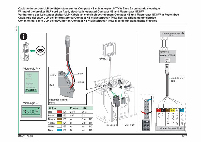
Câblage du cordon ULP de disjoncteur sur les Compact NS et Masterpact NT/NW fixes à commande électrique Wiring of the breaker ULP cord on fixed, electrically operated Compact NS and Masterpact NT/NW Verdrahtung des Leistungsschalter-ULP-Kabels an elektrisch betriebenem Compact NS und Masterpact NT/NW in Festeinbau Cablaggio del cavo ULP dell’interruttore su Compact NS e Masterpact NT/NW fissi ad azionamento elettrico Conexión del cable ULP del disyuntor en Compact NS y Masterpact NT/NW fijos de funcionamiento eléctrico
Ipush ON
O OFF
discharged
40
100%
%
OF1OF2OF3OF4MCHPFXFMX1MN
SDE1
UC4UC3UC2UC1COM
SDE1
/RES /M2C /MX2
E1 E2E3E4E
5 E6
BCM ULP MX1 / XF
Micrologic P/H
w
ModbusCom
Address
Baud-rate19.2 k
4W, 2W+ULP
2w+ULP
m enu
100
Micrologic E+ -
External power supply24 V c
+ -FDM121version > V2.0.2
B’ / R
x + D1
A’ / Rx - D
0
B / Tx + D
1
A / Tx - D0
0 V
24 V
E1 E2 E3 E4 E5 E6
customer terminal block
Red
WhiteBlue
Black
Breaker ULPcord
customer terminal block
Colour Europe USARed E1 24 V 24 VBlack E2 0 V 0 VBrown E3 A Out- D0Yellow E4 B Out+ D1White E5 A' In- D0Blue E6 B' In+ D1
FDM121
DB
4011
76
�/12S1A73172-00
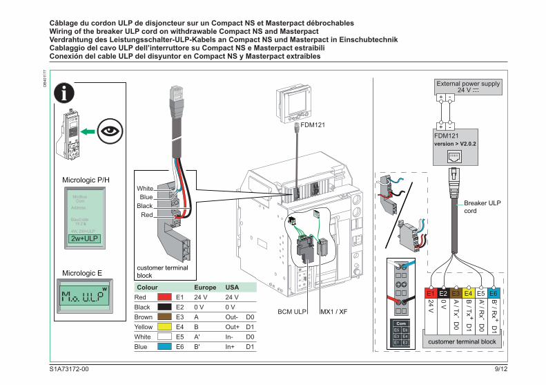
Câblage du cordon ULP de disjoncteur sur un Compact NS et Masterpact débrochables Wiring of the breaker ULP cord on withdrawable Compact NS and Masterpact Verdrahtung des Leistungsschalter-ULP-Kabels an Compact NS und Masterpact in Einschubtechnik Cablaggio del cavo ULP dell’interruttore su Compact NS e Masterpact estraibili Conexión del cable ULP del disyuntor en Compact NS y Masterpact extraíbles
40
100%
%
E1 E2 E3 E4 E5 E6
BCM ULP MX1 / XF
Micrologic P/H
w
ModbusCom
Address
Baud-rate19.2 k
4W, 2W+ULP
2w+ULP
m enu
100
Micrologic E
+ -
External power supply24 V c
+ -FDM121version > V2.0.2
B’ / R
x + D1
A’ / Rx - D
0
B / Tx + D
1
A / Tx - D0
0 V
24 V
E1 E2 E3 E4 E5 E6
customer terminal block
Breaker ULPcord
customer terminal block
FDM121
WhiteBlue
RedBlack
Colour Europe USARed E1 24 V 24 VBlack E2 0 V 0 VBrown E3 A Out- D0Yellow E4 B Out+ D1White E5 A' In- D0Blue E6 B' In+ D1
DB
4011
77

10/12S1A73172-00
Notes / Notes / Note / Note / Notas
11/12S1A73172-00
Notes / Notes / Note / Note / Notas
Schneider Electric Industries SAS35 rue Joseph MonierCS 30323F - 92506 Rueil Malmaison Cedex
RCS Nanterre 954 503 439Capital social 896 313 776 €www.schneider-electric.com
S1A73172-00 12/2010
Printed on recycled paper.
Designed by: Schneider ElectricPrinted by:
En raison de l'évolution des normes et du matériel, les caractéristiques et cotes d'encombrement données ne nous engagent qu'après confirmation par nos services.As standards, specifications, designs and dimensions develop from time to time, always ask for confirmation of the information given in this publication.
© 2
010
Sch
neid
er E
lect
ric. A
ll rig
hts
rese
rved
.