Jing Zhao Oliver T. Bruns He Wei Peng Guo Jian Cui Ou Chen ... · 9Cornell High Energy Synchrotron...
16
Magneto-Fluorescent Core-Shell Supernanoparticles Ou Chen 1 , Lars Riedemann 2 , Fred Etoc 3 , Hendrik Herrmann 4,5 , Mathieu Coppey 3 , Mariya Barch 6 , Christian T. Farrar 7 , Jing Zhao 1 , Oliver T. Bruns 1 , He Wei 1 , Peng Guo 8 , Jian Cui 1 , Russ Jensen 1 , Yue Chen 1 , Daniel K. Harris 1 , Jose M. Cordero 1 , Zhongwu Wang 9 , Alan Jasanoff 6,10,11 , Dai Fukumura 2 , Rudolph Reimer 4 , Maxime Dahan 3 , Rakesh K. Jain 2 , and Moungi G. Bawendi 1,* 1 Department of Chemistry, Massachusetts Institute of Technology, 77 Massachusetts Ave., Cambridge, MA 02139 (USA) 2 Massachusetts General Hospital and Harvard Medical School, 100 Blossom St., Boston, MA 02114 (USA) 3 Laboratoire Physico-Chimie Curie, Institut Curie, CNRS UMR168, 75248 Paris (France) 4 Heinrich-Pette-Institute, Martinistrasse 52, 20251 Hamburg (Germany) 5 Bernhard-Nocht-Institute for Tropical Medicine, Bernhard-Nocht-Strasse 74, 20359 Hamburg (Germany) 6 Department of Biological Engineering, Massachusetts Institute of Technology, 77 Massachusetts Ave., Cambridge, MA 02139 (USA) 7 Athinoula A. Martinos Center for Biomedical Imaging, Massachusetts General Hospital, Charlestown, MA 02129 (USA) 8 Vascular Biology Program, Children’s Hospital Boston, Harvard Medical School, 300 Longwood Ave., Boston, MA 02115 (USA) 9 Cornell High Energy Synchrotron Source (CHESS), Wilson Laboratory, Cornell University, Ithaca, NY, 14853 (USA) 10 Department of Brain and Cognitive Sciences, Massachusetts Institute of Technology, 77 Massachusetts Ave., Cambridge, MA 02139 (USA) 11 Department of Nuclear Science and Engineering, Massachusetts Institute of Technology, 77 Massachusetts Ave., Cambridge, MA 02139 (USA) Abstract * Correspondence to: [email protected]. Author contributions O.C. and M.G.B. conceived and designed the project. O.C. performed the bulk of the experimental work with help from L.R., F.E., H.H., M.B., C.F., J.C., P.G. and R.J.. The data was analyzed by O.C., L.R., F.E., H.H., M.C., M.B., C.F., J.Z., O.B., J.C., H.W., P.G., R.J., Z.W. and M.G.B.. All authors discussed the results and took part in producing the manuscript. Competing financial interests The authors declare no competing financial interests. Supplementary information accompanies this paper. NIH Public Access Author Manuscript Nat Commun. Author manuscript; available in PMC 2015 April 09. Published in final edited form as: Nat Commun. ; 5: 5093. doi:10.1038/ncomms6093. NIH-PA Author Manuscript NIH-PA Author Manuscript NIH-PA Author Manuscript
Transcript of Jing Zhao Oliver T. Bruns He Wei Peng Guo Jian Cui Ou Chen ... · 9Cornell High Energy Synchrotron...
Magneto-Fluorescent Core-Shell Supernanoparticles
Ou Chen1, Lars Riedemann2, Fred Etoc3, Hendrik Herrmann4,5, Mathieu Coppey3, Mariya Barch6, Christian T. Farrar7, Jing Zhao1, Oliver T. Bruns1, He Wei1, Peng Guo8, Jian Cui1, Russ Jensen1, Yue Chen1, Daniel K. Harris1, Jose M. Cordero1, Zhongwu Wang9, Alan Jasanoff6,10,11, Dai Fukumura2, Rudolph Reimer4, Maxime Dahan3, Rakesh K. Jain2, and Moungi G. Bawendi1,*
1Department of Chemistry, Massachusetts Institute of Technology, 77 Massachusetts Ave., Cambridge, MA 02139 (USA)
2Massachusetts General Hospital and Harvard Medical School, 100 Blossom St., Boston, MA 02114 (USA)
3Laboratoire Physico-Chimie Curie, Institut Curie, CNRS UMR168, 75248 Paris (France)
4Heinrich-Pette-Institute, Martinistrasse 52, 20251 Hamburg (Germany)
5Bernhard-Nocht-Institute for Tropical Medicine, Bernhard-Nocht-Strasse 74, 20359 Hamburg (Germany)
6Department of Biological Engineering, Massachusetts Institute of Technology, 77 Massachusetts Ave., Cambridge, MA 02139 (USA)
7Athinoula A. Martinos Center for Biomedical Imaging, Massachusetts General Hospital, Charlestown, MA 02129 (USA)
8Vascular Biology Program, Children’s Hospital Boston, Harvard Medical School, 300 Longwood Ave., Boston, MA 02115 (USA)
9Cornell High Energy Synchrotron Source (CHESS), Wilson Laboratory, Cornell University, Ithaca, NY, 14853 (USA)
10Department of Brain and Cognitive Sciences, Massachusetts Institute of Technology, 77 Massachusetts Ave., Cambridge, MA 02139 (USA)
11Department of Nuclear Science and Engineering, Massachusetts Institute of Technology, 77 Massachusetts Ave., Cambridge, MA 02139 (USA)
Abstract
*Correspondence to: [email protected].
Author contributionsO.C. and M.G.B. conceived and designed the project. O.C. performed the bulk of the experimental work with help from L.R., F.E., H.H., M.B., C.F., J.C., P.G. and R.J.. The data was analyzed by O.C., L.R., F.E., H.H., M.C., M.B., C.F., J.Z., O.B., J.C., H.W., P.G., R.J., Z.W. and M.G.B.. All authors discussed the results and took part in producing the manuscript.
Competing financial interestsThe authors declare no competing financial interests.
Supplementary information accompanies this paper.
NIH Public AccessAuthor ManuscriptNat Commun. Author manuscript; available in PMC 2015 April 09.
Published in final edited form as:Nat Commun. ; 5: 5093. doi:10.1038/ncomms6093.
NIH
-PA
Author M
anuscriptN
IH-P
A A
uthor Manuscript
NIH
-PA
Author M
anuscript
Magneto-fluorescent particles have been recognized as an emerging class of materials that exhibit
great potential in advanced applications. However, synthesizing such magneto-fluorescent
nanomaterials that simultaneously exhibit uniform and tunable sizes, high magnetic content
loading, maximized fluorophore coverage at the surface, and a versatile surface functionality has
proven challenging. Here we report a simple approach for co-assembling magnetic nanoparticles
with fluorescent quantum dots to form colloidal magneto-fluorescent supernanoparticles.
Importantly, these supernanoparticles exhibit a superstructure consisting of a close packed
magnetic nanoparticle “core” which is fully surrounded by a “shell” of fluorescent quantum dots.
A thin layer of silica-coating provides high colloidal stability and biocompatiblity and a versatile
surface functionality. We demonstrate that after surface pegylation, these silica-coated magneto-
fluorescent supernanoparticles can be magnetically manipulated inside living cells while being
optically tracked. Moreover, our silica-coated magneto-fluorescent supernanoparticles can also
serve as an in vivo multi-photon and magnetic resonance dual-modal imaging probe.
Introduction
The design and fabrication of materials that simultaneously contain more than one
functional component, so-called multifunctional materials, is an active research area with the
potential to impact a wide range of technological applications1–4. Among a variety of
possible building blocks, colloidal nanocrystals have proven to be ideal for generating
higher-order architectures either in random or ordered assemblies5–12. In particular, co-
assembling two types of nanocrystals with distinct properties into larger colloidal particles,
especially at the mesoscopic scale, offers the possibility of producing new classes of
nanoparticles (i.e., supernanoparticles (SPs)) with a set of combined properties, all the while
maintaining the colloidal nature of their building blocks13. Moreover, synthesizing SPs with
well defined internal structures, although challenging, may be critical in generating novel
properties. In particular, magneto-fluorescent particles have been recognized as an emerging
class of materials that have potential in advanced applications3, 14–17. To fully realize their
potential and to optimize their performance, the following design criteria need to be
simultaneously fulfilled: uniform and tunable sizes, high magnetic content loading for
synergistic magnetic properties, maximized loading of fluorophores at the surface for an
optimized fluorescence signal, long-term colloidal stability, and a versatile surface
functionality for the varied requirements of different applications, especially in biology. A
simple and versatile synthetic strategy gives the additional benefit of a relatively rapid
materials fabrication. In the past decade, much effort has been devoted to developing
synthetic strategies for the fabrication of such magneto-fluorescent materials, including
heterostructure crystal growth18–21, co-encapsulation into organic structures (e.g., oil
droplet, lipid micelle, block co-polymer) or inorganic materials (e.g., silica)22–29, template-
based synthesis via either chemical bonding or physical attachment30–32.
Our method is based on co-assembling CdSe-CdS core-shell quantum dots (QDs) with
Fe3O4 magnetic nanoparticles (MNPs) into colloidal SPs. In this co-assembly process, close
packed MNPs form a “core” that is subsequently coated with a “shell” of QDs, resulting in
the formation of “core-shell” structured SPs (CS-SPs). Additional thermal treatment
transforms the randomly assembled “core” MNPs into a periodic assembly with a face-
Chen et al. Page 2
Nat Commun. Author manuscript; available in PMC 2015 April 09.
NIH
-PA
Author M
anuscriptN
IH-P
A A
uthor Manuscript
NIH
-PA
Author M
anuscript
centered-cubic (fcc) superlattice. The CS-SPs can be over coated with a thin silica layer,
offering them further surface functionality and colloidal stability. Importantly, these silica-
coated CS-SPs (silica-CS-SPs) exhibit uniform and tunable sizes, high magnetic content
loading, maximized fluorophore loading on the surface, substantial colloidal stability, and
versatile surface functionality. We demonstrate that after functionalizing with polyethylene
glycol (PEG), silica-CS-SPs can be magnetically manipulated inside living cells while being
optically tracked. Moreover, our silica-CS-SPs can also serve as a dual-modal imaging
probe for in vivo multi-photon (MP) and magnetic resonance (MR) imaging.
Results and discussion
CdSe-CdS core-shell QDs (9.0 ± 0.4 nm) and superparamagnetic Fe3O4 MNPs (5.9 ± 0.3
nm) were used to demonstrate the formation of multifunctional magneto-fluorescent SPs
(Supplementary Fig. 1). As shown schematically in Fig. 1a, hydrophobic QDs and MNPs
were mixed and transferred to an aqueous solution using dodecyltrimethylammonium
bromide (DTAB) as a surfactant. The resultant micelle aqueous solution was quickly
injected into a poly(vinylpyrrolidone) (PVP) ethylene glycol (EG) solution. After 30 min
stirring, the PVP stabilized SPs were isolated by centrifugation and re-dispersed into
ethanol. Large-area transmission electron microscopy (TEM) and scanning electron
microscopy (SEM) images show that the resulting spherical SPs have an average diameter of
~120 nm (σ~11%) (Fig. 1b, Supplementary Fig. 2). Dynamic light scattering (DLS)
measurements give a hydrodynamic (HD) diameter of ~170 nm for ethanol-dispersed SPs
(Supplementary Fig. 3). The apparent increased HD diameter relative to that in TEM and
SEM is due to the presence of a PVP polymer surface layer and its low contrast in TEM and
SEM imaging. Higher magnification TEM images demonstrate that each SP is composed of
close packed nanoparticles (Fig. 1c). Due to the uniformity of the QD and MNP building
blocks (σ~4.4% for QDs and σ~5.0% for MNPs) and their different sizes (9.0 nm for QDs
and 5.9 nm for MNPs) (Supplementary Fig. 1), the QDs and MNPs can be easily
distinguished in TEM. TEM images in Fig. 1c and 1d illustrate that each SP contains both
QDs and MNPs. This result is consistent with a series of additional observations including
absorption and PL spectra (Fig. 1e), wide angle X-ray diffraction (Fig. 1f), particle
movement under external magnetic attraction (Fig. 1g), and energy dispersive X-ray
spectroscopy (EDS) (Fig. 1h). EDS gives an elemental composition of 27.3% cadmium and
72.7% iron, in agreement with the initially introduced quantities of QDs and MNPs (Fig. 1h,
inset). A phase separation occurs inside each SP, in which MNPs preferentially assemble to
form a magnetic “core”, with the QDs forming a fluorescent “shell” (Fig. 1c and d).
Scanning TEM (STEM) elemental mapping and line scan (Fig. 1i and j), and high-resolution
TEM characterization (Supplementary Fig. 4) further demonstrate this “core-shell”
superstructure. Three-dimensional (3D) TEM tomography is also consistent with only MNPs
inside the SP core (Supplementary Movie 1). With these observations, we speculate that the
formation of this super “core-shell” structure is most likely driven by enhanced forces which
originate from the magnetic dipole-dipole interactions of MNPs (i.e., Fe3O4 MNPs) in
addition to the solvophobic interactions that drive the assembly of both MNPs and QDs (Fig.
1a). The same protocol, but with small QDs (6.0 ± 0.3 nm) and large MNPs (9.6 ± 0.4 nm),
yields the same CS-SP architecture (small QDs as “shell” and large MNPs as “core”)
Chen et al. Page 3
Nat Commun. Author manuscript; available in PMC 2015 April 09.
NIH
-PA
Author M
anuscriptN
IH-P
A A
uthor Manuscript
NIH
-PA
Author M
anuscript
(Supplementary Fig. 5 and Supplementary Movie 2). This control experiment excludes
particle size as the dominant parameter for the formation of the “core-shell” superstructure.
Recent studies have shown that supercrystalline SPs can be obtained through a thermal
annealing process33–35. We performed a thermal annealing of our CS-SPs. TEM images
show that upon annealing at 80 °C for 24 hours, the “core-shell” structure is preserved, but
the core MNPs form an ordered structure and display highly ordered and atomic-like
superlattice fringes (Fig. 2a–d). Analyses of the observed fringes and superlattice
orientations suggest that the core particles in CS-SPs form a fcc superlattice with an
estimated lattice constant of 10.5 ± 0.2 nm (Fig. 2a–c). Figure 2a–c display typical TEM
images of these crystalline CS-SPs viewed along the [001], [011] and [11 ̄2̄] zone axes,
respectively. Typical TEM images further indicate that some CS-SPs include defects and
stacking faults (Fig. 2d). High-resolution synchrotron small angle x-ray scattering (SAXS)
characterization unambiguously confirms the assignment of a highly ordered fcc superlattice
(Fig. 2e). The first broad SAXS peak represents strong diffuse scattering from the randomly
distributed “shell” QDs, but other SAXS peaks are well assigned to Bragg peaks from an
ideal fcc superlattice, corresponding to the Fm3m space group (Fig. 2e). The calculated
lattice constant is 10.4 ± 0.2 nm (Supplementary Table 1), consistent with TEM
observations (Fig. 2a–d). Correlating the SAXS-defined nearest inter-particle spacing of 7.3
nm to the average MNP size of 5.9 nm gives an inter-particle distance of 1.4 nm, consistent
with coiled and intercalated oleate ligands on MNPs surfaces36, 37. Given the average
diameter of CS-SPs, the number of MNPs inside each CS-SP is estimated at ~2020 ± 230,
with a packing density of 39%. Upon fine-tuning the ratio of nanoparticles (both QDs and
MNPs) to DTAB surfactant and the ratio of QDs to MNPs (Supplementary Table 2), we can
obtain a wide range of the crystalline CS-SPs with an average diameter ranging from ~80
nm to ~360 nm (Fig. 2f–i). Higher magnification TEM images clearly show the core-shell
structure of individual crystalline SPs for all sizes (Fig. 2j–m).
With their combination of both magnetism and fluorescence, CS-SPs have potential in
various applications and technological devices. However, feasible applications, especially in
biological systems, often require additional surface functionality, and this can be
significantly hindered with CS-SPs that have a PVP polymer surface. To overcome this
challenge and improve biocompatibility and colloidal stability, we encapsulate CS-SPs (~ 80
nm) with a thin silica shell through a sol-gel process38, 39. TEM characterization shows that
each CS-SP is uniformly coated with a 10.6 ± 0.7 nm thick silica shell (Fig. 3a). STEM line
scan, element mapping and 3D TEM tomography show that the core-shell superstructure is
preserved (Fig. 3b, Supplementary Fig. 6 and Supplementary Movie 3). DLS measurements
reveal that the HD diameter dramatically decreases from ~ 130 nm to ~ 100 nm, similar to
the TEM-determined size of ~100 nm (Fig. 3a and Supplementary Fig. 7). The decrease in
HD size implies a complete removal of the bulky PVP layer. Importantly, these silica-coated
CS-SPs (silica-CS-SPs) display a high degree of colloidal stability. No measureable changes
in both the PL intensity and HD size can be observed after 6-month at 4 °C (Fig. 3c). These
silica-CS-SPs exhibit superparamagnetism at room temperature with a saturation
magnetization of 15.2 emu g−1 (1.4 × 10⁻¹⁴ emu per particle) (Fig. 3d and Supplementary
Fig. 8 and Supplementary Table 3). The decreased magnetization compared to that of free
Fe3O4 MNPs (63.7 emu g−1, Supplementary Fig. 9) is due to non-magnetic components
Chen et al. Page 4
Nat Commun. Author manuscript; available in PMC 2015 April 09.
NIH
-PA
Author M
anuscriptN
IH-P
A A
uthor Manuscript
NIH
-PA
Author M
anuscript
inside each silica-CS-SP (the QDs, the silica layer, and the organic ligands) with a mass
percentage of 75.2% (Supplementary Fig. 10 and Supplementary Table 3). The PL QY of
the silica-CS-SPs was measured to be ~12% using a 405 nm excitation light, comparable
with that of the PVP-coated CS-SPs (Supplementary Fig. 11). The decreased QY compared
to free QDs (PL QY of 94%) is in large part a result of the MNPs strongly absorbing this
wavelength light. Under the illumination of a continuous wave laser at a power density of 22
W cm−2 for ~ 2800 second, silica-CS-SPs did not show evidence either of blinking or photo-
bleaching (Fig. 3e), thus making them an ideal tool for single particle tracking. To
demonstrate the silica-layer enabled surface functionality, methoxy-polyethylene-glycol
silane (mPEG-silane, MW5000) was conjugated to the CS-SPs (Supplementary Fig. 12).
The resulting particles have nearly neutral surfaces (−5.1 ± 2.3 mV, Supplementary Fig. 13),
minimal cell toxicity (Supplementary Fig. 14) and minimal protein-adsorption
(Supplementary Fig. 15). These features allow for the ultimate use of these CS-SPs in
various biological systems.
One of the persistent challenges in cell biology is to understand how a series of biomolecular
activities can be integrated and modulated in the intracellular space. Several recent
experiments have shown how magnetic nanoparticles could be used as actuators for remote
control of signaling processes at the single cell level with subcellular resolution40, 41. Yet,
experimental failure is quite common, mainly due to particle polydispersities in size and
magnetic content that not only make microinjection of nanoparticles difficult, but also
render intracellular manipulation fragile due to the viscoelasticity of the cytoplasm. As a
consequence, there is a pressing need for the fabrication of nanoparticles that have a small
and uniform size but still show strong magnetism for efficient response, and are also highly
fluorescent for monitoring their intracellular spatial distribution. The specifications of our
silica-CS-SPs meet all these requirements. Given a particle diameter of ~100 nm, forces on
the order of 1 pN, similar to the force generated by a molecular motor42, can be generated
with a magnetic tip (Fig. 4a). These forces were sufficient to efficiently manipulate silica-
CS-SPs across whole cells within minutes (Fig. 4b–d and Supplementary Movie 4 and 5).
The movement of the silica-CS-SPs appears to be only marginally hindered by the
cytoplasmic meshwork (Fig. 4b–d). The silica-CS-SPs are bright enough that their
individual trajectories can be tracked with great accuracy (a pointing accuracy of ~15nm)
throughout their transport within the cytoplasm (Fig. 4b and c). The key for success and
reproducibility of these experiments is the superior homogeneity in both particle size and
magnetic content of these silica-CS-SPs. We thus expect silica-CS-SPs, once decorated with
targeting or signaling molecules, to constitute a powerful platform for the magnetic control/
manipulation of intracellular processes.
Another biomedical application of interest of MNPs is their use as markers for MR imaging.
The T2-weighted MR contrast is dramatically enhanced in silica-CS-SPs due to the high
degree of aggregation of the core MNPs15, 43–46, giving a T2 relaxivity of 402.7 mM−1S−1, ~
6.2 times larger than for the individual MNPs (Supplementary Fig. 16). Such a high T2
relaxivity coupled with excellent photoluminescence properties, make silica-CS-SPs ideal
MP/MR dual-modal in vivo imaging probes. As a demonstration, mPEG functionalized
silica-CS-SPs with a HD diameter of ~120 nm (200μL, 2mg mL−1) were intravenously
Chen et al. Page 5
Nat Commun. Author manuscript; available in PMC 2015 April 09.
NIH
-PA
Author M
anuscriptN
IH-P
A A
uthor Manuscript
NIH
-PA
Author M
anuscript
injected into mice bearing brain metastasis of a murine mammary carcinoma (MCaIV)47.
Both the optical MP images (Fig 4e–g) and T2-weighted MR images (Fig 4h–j) reveal that
silica-CS-SPs selectively accumulate in the tumor region 24 hours after injection through an
enhanced permeation and retention effect48. These experiments demonstrate the potential of
our silica-CS-SPs as unique powerful in vivo MP/MR dual-modal imaging probe.
In conclusion, we demonstrate a simple and effective method for assembling CdSe-CdS
QDs with Fe3O4 MNPs into colloidal SPs with a “core-shell” superstructure. These SPs
have remarkably narrow size distributions, so that the properties of single SPs reliably map
onto the properties of the ensemble. Additional thermal annealing drives the crystallization
of the “core” MNPs into a highly ordered supercrystal with an ideal fcc superlattice. The
CS-SPs can be easily coated with a thin silica layer, providing surface functionality and
colloidal stability as well as biocompatibility. Importantly, these silica-CS-SPs
simultaneously exhibit uniform and tunable sizes, high magnetic content loading,
maximized fluorophore loading on the surface, substantial colloidal stability, and versatile
surface functionality. These features allow the utilization of these magneto-fluorescent SPs
for in vitro intracellular manipulation and in vivo MR/MP dual-mode imaging. Given the
versatility of our assembly strategy, we anticipate that, driven by various applications, SPs
with a variety of compositions will also be achieved using this method.
Methods
Synthesis of QDs and MNPs nanocrystals
High-quality uniform CdSe-CdS core-shell QDs and Fe3O4 MNPs with tunable sizes are
synthesized according to the literature methods49, 50. Detailed information regarding
synthesis can be found in the Supplementary Methods. As-synthesized nanocrystals were
purified by precipitation with acetone and were dispersed in chloroform to form stock
solutions with concentrations of 20–50 mg mL−1.
Synthesis of CS-SPs with a random magnetic “core”
In a typical synthesis, 1 mL chloroform solution containing 4 mg 9.0-nm QDs and 6 mg 5.9-
nm MNPs was injected to 1 mL dodecyltrimethylammonium bromide (DTAB) aqueous
solution (20 mg mL−1 in Nanopure water). The solution was thoroughly mixed by vortex for
5 seconds. After removing the chloroform from the mixture by blowing Ar at room
temperature, a clear QD-MNP-micelle aqueous solution was obtained. This QD-MNP-
micelle solution was swiftly injected into a 5mL poly(vinylpyrrolidone) (PVP, MW 55000)
ethylene glycol (EG) solution (2 mM) under vigorous stirring with a stirring speed of 700
rpm for 30 min at room temperature. The resulting CS-SPs were isolated by centrifugation,
re-dispersed in ethanol and stored at ~4 °C.
Synthesis of CS-SPs with a supercrystalline magnetic “core”
The synthesis procedure is the same as the synthesis of CS-SPs described above, except that
an additional thermal annealing process was carried out after the CS-SPs synthesis. In this
thermal annealing process, the resulting CS-SPs in PVP/EG solution was heated to 80 °C
with a slow stirring speed (300 rpm) and kept for 24 hours before cooling to room
Chen et al. Page 6
Nat Commun. Author manuscript; available in PMC 2015 April 09.
NIH
-PA
Author M
anuscriptN
IH-P
A A
uthor Manuscript
NIH
-PA
Author M
anuscript
temperature. The resulting supercrystalline CS-SPs were isolated by centrifugation,
redispersed in ethanol and stored at ~ 4 °C as a stock solution.
Synthesis of silica-CS-SPs
For a typical synthesis, 2 mg CS-SPs was dissolved in 20 mL ethanol. Under vigorous
stirring, 3 mL deionized-water (DI-water) and 1 mL NH3·H2O solution was added dropwise
in the reaction solution, followed by the addition of 50 μL TEOS. The final solution was
kept stirring at room temperature for 20 min. The resulting silica-CS-SPs were isolated by
centrifugation, washed with deionized-water and dissolved in 2 mL DI-water and stored at
~4 °C.
Synthesis of mPEG-silane functionalized silica-CS-SPs
2 mL silica-CS-SPs were diluted in 10 mL DI-water. Under magnetic stirring, 50 μL
NH3·H2O solution and 20 μL TEOS were added into the solution, sequentially. After the
mixture solution was heated to 70 °C, 1 mL mPEG-silane (MW 5000) aqueous solution
(0.02 M) was dropped in. The reaction solution was kept stirring at 70 °C for 3 hrs and then
stirred at room temperature for another 15 hrs. The resulting mPEG-silane functionalized
silica-CS-SPs were isolated by centrifugation, washed three times with nanopure water and
finally dissolved in 1 mL phosphate buffer solution (PBS, 1X) and stored at ~4 °C fridge.
Magnetic manipulation of the silica-CS-SPs in living cells
For manipulation in living cells, HeLa cells and Cos7 cell lines were cultured at 37°C in 5%
CO2 in Dulbecco’s modified Eagle’s medium (DMEM) supplemented with 10% fetal calf
serum. For imaging and manipulation, cells were grown on 25 mm glass coverslips.
Experiments were performed at 37 °C in a heating chamber placed on the inverted
microscope. Microinjection was performed with the same borosilicate needles as described
above and filled with a concentrated solution of SPs. After microinjection, the cells were left
for 20 minutes recovery. In order to bring the tip close to the sample with the orientation
adapted to each unique cell morphology, the magnetic tip was attached to a circular teflon
holder, allowing us to rotate the tip in respect to the optical axis of the microscope, as
described in Etoc et al.41. Tracking of the manipulated SPs was performed semi-manually
using the Manual Tracking plugin of ImageJ.
Intravital multiphoton microscopy
All animal procedures were carried out following the Public Health Service Policy on
Humane Care of Laboratory Animals and approved by the Institutional Animal Care and
Use Committee of the Massachusetts General Hospital. Imaging studies were carried out
using a MCaIV cranial window model in C3H mice51. MCaIV tumor cell pellet (~ 2.5×10⁵
cells) is injected into the exposed parenchymal space at about 0.1 mm depth. In vivo imaging
is performed on established tumors on day 9 after pellet implantation.
In vivo imaging—Fluorescein isothiocyanate–dextran/phosphate buffered saline solution
(FITC-Dextran) was prepared for in vivo vessel tracing in a concentration of 10 mg mL−1.
Following tail vain injection of 100 μL of FITC-Dextran, a baseline vessel image was
Chen et al. Page 7
Nat Commun. Author manuscript; available in PMC 2015 April 09.
NIH
-PA
Author M
anuscriptN
IH-P
A A
uthor Manuscript
NIH
-PA
Author M
anuscript
acquired using multiphoton imaging described previously47 on a custom-built multiphoton
laser-scanning microscope using confocal laser-scanning microscope body (Olympus 300;
Optical Analysis Corp.) and a broadband femtosecond laser source (High Performance
MaiTai, Spectra-Physics). After acquisition of a baseline image, mPEG-silane
functionalized silica-CS-SPs solution (200 μL, 2 mg mL−1) were intravenously injected via
tail vein. Image slices were taken with 400 mW at a wavelength of 820 nm in three ROIs in
tumor area and one in the healthy contra-lateral hemisphere. Images were taken with depths
from 0 – 150 μm. Imaging studies were performed with a 20X magnification, 0.95NA water
immersion objective (Olympus XLUMPlanFl, 1-UB965, Optical Analysis). Image analysis
was carried out using ImageJ.
In vivo magnetic resonance imaging study
All experiments were performed on a 9.4 Tesla magnet (Magnex Scientific Ltd, Oxford,
UK) equipped with a 60 mm inner diameter gradient coil (Resonance Research, Billerica,
MA) and interfaced with a Bruker MRI console (Bruker Biospin, Billerica, MA). The
gradient coil has a maximum strength of 1500 mT m−1 and a rise time of 100 μs. Images
were acquired using a home built mouse head bird-cage coil. Mice were positioned on a
custom made mouse cradle and anesthetized with 1.5% isoflurane in 50/50 O2/medical air
mixture with total flow rate of 1200 ml min−1.
T2-weighted RARE MRI—T2-weighted Rapid Acquisition with Refocused Echoes
(RARE) images were acquired with the following acquisition parameters: TE = 10, RARE
factor = 8, TR = 2500 ms, NA = 4, 15 image slices, 0.5 mm slice thickness, 125 μm in-plane
resolution. Tumor volume was determined from the T2 hyperintense tumor region of the
brain.
T2 Maps—T2 maps were generated from multi-echo spin-echo and multi-echo gradient-
echo images, respectively, using a custom written MATLAB program for voxel-wise fitting
of the T2 relaxation times. Multi-echo spin-echo image acquisition parameters were: TE =
10 ms, 15 echoes with 10 ms increment, TR = 2.5 s, 2 averages, FOV = 1.6 cm, matrix =
128 × 128 (in-plane resolution 125 μm), slice thickness = 0.5 mm, 15 image slices. Multi-
echo gradient-echo image acquisition parameters were: TE = 2.5 ms, 10 echoes with 2.5 ms
increment, TR = 1.5 s, 4 averages, FOV = 1.6 cm, matrix = 96 × 96, slice thickness = 0.5
mm, 15 image slices.
Supplementary Material
Refer to Web version on PubMed Central for supplementary material.
Acknowledgments
This work received support from the NIH through 5-U54-CA151884 (M.G.B.), P01-CA080124 (R.K.J.), R01-CA126642 (M.G.B., D.F., R.K.J.), R01-CA163815 (R.K.J.), R01-CA096915 (D.F.), the ARO through the Institute for Soilder Nanotechnologies (W911NF-13-D-0001, M.G.B.), the Department of Energy through DE-FG02-07ER46454 (M.G.B.), the NIH funded Laser Biomedical Resource Center (LBRC) 9-P41-EB015871-26A1 (M.G.B.), Federal Share/National Cancer Institute Proton Beam Program Income Grants (R.K.J.), Mildred-Scheel-Fellowship (Deutsche Krebshilfe) by the German Cancer Aid (L.R.), a DoD Breast Cancer Research Innovator award (W81XWH-10-1-0016) (R.K.J.), the Human Frontier Science Program (grant no. RGP0005/2007) (M.D. and
Chen et al. Page 8
Nat Commun. Author manuscript; available in PMC 2015 April 09.
NIH
-PA
Author M
anuscriptN
IH-P
A A
uthor Manuscript
NIH
-PA
Author M
anuscript
M.G.B) and the program ANR-10-IDEX-0001-02 PSL (M.D.). M.B. and A.J. are supported by the NIH through R01-DA028299 and R01-NS076462 to A.J.. H.H. was supported by the Federal Ministry of Education and Research (BMBF, 01EZ0829). O.T.B. is supported by EMBO long-term fellowship. CHESS is supported by the NSF & NIH/NIGMS via NSF award DMR-0936384 (Z.W.). This work made use of the MRSEC Shared Experimental Facilities at MIT, supported by the National Science Foundation under award number DMR-08-19762.
References
1. Gibson RF. A review of recent research on mechanics of multifunctional composite materials and structures. Compos Struct. 2010; 92:2793–2810.
2. Suh WH, Suh YH, Stucky GD. Multifunctional nanosystems at the interface of physical and life sciences. Nano Today. 2009; 4:27–36.
3. Bigall NC, Parak WJ, Dorfs D. Fluorescent, magnetic and plasmonic-Hybrid multifunctional colloidal nano objects. Nano Today. 2012; 7:282–296.
4. Lee JE, Lee N, Kim T, Kim J, Hyeon T. Multifunctional mesoporous silica nanocomposite nanoparticles for theranostic applications. Accounts Chem Res. 2011; 44:893–902.
5. Macfarlane RJ, et al. Nanoparticle superlattice engineering with DNA. Science. 2011; 334:204–208. [PubMed: 21998382]
6. Wang T, et al. Self-assembled colloidal superparticles from nanorods. Science. 2012; 338:358–363. [PubMed: 23087242]
7. Dong AG, Chen J, Vora PM, Kikkawa JM, Murray CB. Binary nanocrystal superlattice membranes self-assembled at the liquid-air interface. Nature. 2010; 466:474–477. [PubMed: 20651688]
8. Talapin DV, et al. Quasicrystalline order in self-assembled binary nanoparticle superlattices. Nature. 2009; 461:964–967. [PubMed: 19829378]
9. Redl FX, Cho KS, Murray CB, O’Brien S. Three-dimensional binary superlattices of magnetic nanocrystals and semiconductor quantum dots. Nature. 2003; 423:968–971. [PubMed: 12827196]
10. Xia YS, et al. Self-assembly of self-limiting monodisperse supraparticles from polydisperse nanoparticles. Nat Nanotechnol. 2011; 6:580–587. [PubMed: 21857686]
11. Zhang YG, Lu F, Yager KG, van der Lelie D, Gang O. A general strategy for the DNA-mediated self-assembly of functional nanoparticles into heterogeneous systems. Nat Nanotechnol. 2013; 8:865–872. [PubMed: 24141539]
12. Quan ZW, Fang JY. Superlattices with non-spherical building blocks. Nano Today. 2010; 5:390–411.
13. Lu ZD, Yin YD. Colloidal nanoparticle clusters: functional materials by design. Chem Soc Rev. 2012; 41:6874–6887. [PubMed: 22868949]
14. Bakalova R, Zhelev Z, Aoki I, Kanno I. Designing quantum-dot probes. Nat Photonics. 2007; 1:487–489.
15. Bruns OT, et al. Real-time magnetic resonance imaging and quantification of lipoprotein metabolism in vivo using nanocrystals. Nat Nanotechnol. 2009; 4:193–201. [PubMed: 19265850]
16. Corr SA, Rakovich YP, Gun’ko YK. Multifunctional magnetic-fluorescent nanocomposites for biomedical applications. Nanoscale Research Letters. 2008; 3:87–104.
17. Kim J, et al. Multifunctional uniform nanoparticles composed of a magnetite nanocrystal core and a mesoporous silica shell for magnetic resonance and fluorescence imaging and for drug delivery. Angew Chem Int Edit. 2008; 47:8438–8441.
18. Kwon KW, Shim M. gamma-Fe2O3/II-VI sulfide nanocrystal heterojunctions. J Am Chem Soc. 2005; 127:10269–10275. [PubMed: 16028938]
19. Gu HW, Zheng RK, Zhang XX, Xu B. Facile one-pot synthesis of bifunctional heterodimers of nanoparticles: A conjugate of quantum dot and magnetic nanoparticles. J Am Chem Soc. 2004; 126:5664–5665. [PubMed: 15125648]
20. Trinh TT, Mott D, Thanh NTK, Maenosono S. One-pot synthesis and characterization of well defined core-shell structure of FePt@CdSe nanoparticles. Rsc Adv. 2011; 1:100–108.
21. Gao JH, et al. Intracellular spatial control of fluorescent magnetic nanoparticles. J Am Chem Soc. 2008; 130:3710–3711. [PubMed: 18314984]
Chen et al. Page 9
Nat Commun. Author manuscript; available in PMC 2015 April 09.
NIH
-PA
Author M
anuscriptN
IH-P
A A
uthor Manuscript
NIH
-PA
Author M
anuscript
22. Ruan G, et al. Simultaneous magnetic manipulation and fluorescent tracking of multiple individual hybrid nanostructures. Nano Lett. 2010; 10:2220–2224. [PubMed: 20450169]
23. Kim BS, Taton TA. Multicomponent nanoparticles via self-assembly with cross-linked block copolymer surfactants. Langmuir. 2007; 23:2198–2202. [PubMed: 17279714]
24. Mandal SK, et al. Encapsulation of magnetic and fluorescent nanoparticles in emulsion droplets. Langmuir. 2005; 21:4175–4179. [PubMed: 15835991]
25. Kim J, et al. Magnetic fluorescent delivery vehicle using uniform mesoporous silica spheres embedded with monodisperse magnetic and semiconductor nanocrystals. J Am Chem Soc. 2006; 128:688–689. [PubMed: 16417336]
26. Yi DK, et al. Silica-coated nanocomposites of magnetic nanoparticles and quantum dots. J Am Chem Soc. 2005; 127:4990–4991. [PubMed: 15810812]
27. Park JH, von Maltzahn G, Ruoslahti E, Bhatia SN, Sailor MJ. Micellar hybrid nanoparticles for simultaneous magnetofluorescent imaging and drug delivery. Angew Chem Int Edit. 2008; 47:7284–7288.
28. Di Corato R, et al. Multifunctional Nanobeads Based on Quantum Dots and Magnetic Nanoparticles: Synthesis and Cancer Cell Targeting and Sorting. ACS Nano. 2011; 5:1109–1121. [PubMed: 21218823]
29. Shen JM, et al. Luminescent/Magnetic Hybrid Nanoparticles with Folate-Conjugated Peptide Composites for Tumor-Targeted Drug Delivery. Bioconjugate Chem. 2012; 23:1010–1021.
30. Insin N, et al. Incorporation of iron oxide nanoplarticles and quantum dots into silica microspheres. ACS Nano. 2008; 2:197–202. [PubMed: 19206619]
31. Lu ZD, et al. Direct assembly of hydrophobic nanoparticles to multifunctional structures. Nano Lett. 2011; 11:3404–3412. [PubMed: 21732588]
32. Kim HM, et al. Synthesis and high performance of magnetofluorescent polyelectrolyte nanocomposites as MR/near-infrared multimodal cellular imaging nanoprobes. ACS Nano. 2011; 5:8230–8240. [PubMed: 21932788]
33. Zhuang JQ, Wu HM, Yang YA, Cao YC. Supercrystalline colloidal particles from artificial atoms. J Am Chem Soc. 2007; 129:14166–14167. [PubMed: 17963395]
34. Zhuang JQ, Wu HM, Yang YA, Cao YC. Controlling colloidal superparticle growth through solvophobic interactions. Angew Chem Int Edit. 2008; 47:2208–2212.
35. Bai F, et al. A versatile bottom-up assembly approach to colloidal spheres from nanocrystals. Angew Chem Int Edit. 2007; 46:6650–6653.
36. Wang ZW, et al. Deviatoric stress driven formation of large single-crystal PbS nanosheet from nanoparticles and in situ monitoring of oriented attachment. J Am Chem Soc. 2011; 133:14484–14487. [PubMed: 21854066]
37. Lee B, et al. Comparison of structural behavior of nanocrystals in randomly packed films and long-range ordered superlattices by time-resolved small angle X-ray scattering. J Am Chem Soc. 2009; 131:16386–16388. [PubMed: 19863066]
38. Piao Y, Burns A, Kim J, Wiesner U, Hyeon T. Designed Fabrication of Silica-Based Nanostructured Particle Systems for Nanomedicine Applications. Adv Funct Mater. 2008; 18:3745–3758.
39. Selvan ST. Silica-coated quantum dots and magnetic nanoparticles for bioimaging applications (Mini-Review). Biointerphases. 2010; 5:Fa110–Fa115. [PubMed: 21171704]
40. Locatelli E, et al. Click chemistry for the assembly of gold nanorods and silver nanoparticles. Chemistry. 2011; 17:9052–9056. [PubMed: 21744406]
41. Etoc F, et al. Subcellular control Rac-GTPase signalling by magnetogenetic manipulation inside living cells. Nat Nanotechnol. 2013; 8:193–198. [PubMed: 23455985]
42. Fisher ME, Kolomeisky AB. The force exerted by a molecular motor. Proc Natl Acad Sci USA. 1999; 96:6597–6602. [PubMed: 10359757]
43. Bigall NC, et al. Colloidal ordered assemblies in a polymer shell-A novel type of magnetic nanobeads for theranostic applications. Chem Mater. 2013; 25:1055–1062.
Chen et al. Page 10
Nat Commun. Author manuscript; available in PMC 2015 April 09.
NIH
-PA
Author M
anuscriptN
IH-P
A A
uthor Manuscript
NIH
-PA
Author M
anuscript
44. Yoon TJ, Lee H, Shao HL, Hilderbrand SA, Weissleder R. Multicore assemblies potentiate magnetic properties of biomagnetic nanoparticles. Adv Mater. 2011; 23:4793–4797. [PubMed: 21953810]
45. Taboada E, Solanas R, Rodriguez E, Weissleder R, Roig A. Supercritical-Fluid-Assisted One-Pot Synthesis of Biocompatible Core(gamma-Fe2O3)/Shell(SiO2) Nanoparticles as High Relaxivity T-2-Contrast Agents for Magnetic Resonance Imaging. Adv Funct Mater. 2009; 19:2319–2324.
46. Xu FJ, Cheng CM, Chen DX, Gu HC. Magnetite Nanocrystal Clusters with Ultra-High Sensitivity in Magnetic Resonance Imaging. Chemphyschem. 2012; 13:336–341. [PubMed: 22095763]
47. Kodack DP, et al. Combined targeting of HER2 and VEGFR2 for effective treatment of HER2-amplified breast cancer brain metastases. Proc Natl Acad Sci USA. 2012; 109:E3119–E3127. [PubMed: 23071298]
48. Jain RK, Stylianopoulos T. Delivering nanomedicine to solid tumors. Nat Rev Clin Oncol. 2010; 7:653–664. [PubMed: 20838415]
49. Chen O, et al. Compact high-quality CdSe-CdS core-shell nanocrystals with narrow emission linewidths and suppressed blinking. Nat Mater. 2013; 12:445–451. [PubMed: 23377294]
50. Park J, et al. Ultra-large-scale syntheses of monodisperse nanocrystals. Nat Mater. 2004; 3:891–895. [PubMed: 15568032]
51. Yuan F, et al. Vascular-permeability and microcirculation of gliomas and mammary carcinomas transplanted in rat and mouse cranial windows. Cancer Res. 1994; 54:4564–4568. [PubMed: 8062241]
Chen et al. Page 11
Nat Commun. Author manuscript; available in PMC 2015 April 09.
NIH
-PA
Author M
anuscriptN
IH-P
A A
uthor Manuscript
NIH
-PA
Author M
anuscript
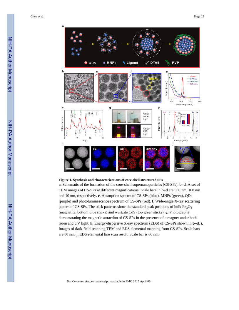
Figure 1. Synthesis and characterizations of core-shell structured SPsa, Schematic of the formation of the core-shell supernanoparticles (CS-SPs). b–d, A set of
TEM images of CS-SPs at different magnifications. Scale bars in b–d are 500 nm, 100 nm
and 10 nm, respectively. e, Absorption spectra of CS-SPs (blue), MNPs (green), QDs
(purple) and photoluminescence spectrum of CS-SPs (red). f, Wide-angle X-ray scattering
pattern of CS-SPs. The stick patterns show the standard peak positions of bulk Fe3O4
(magnetite, bottom blue sticks) and wurtzite CdS (top green sticks). g, Photographs
demonstrating the magnetic attraction of CS-SPs in the presence of a magnet under both
room and UV light. h, Energy-dispersive X-ray spectrum (EDS) of CS-SPs shown in b–d. i, Images of dark-field scanning TEM and EDS elemental mapping from CS-SPs. Scale bars
are 80 nm. j, EDS elemental line scan result. Scale bar is 60 nm.
Chen et al. Page 12
Nat Commun. Author manuscript; available in PMC 2015 April 09.
NIH
-PA
Author M
anuscriptN
IH-P
A A
uthor Manuscript
NIH
-PA
Author M
anuscript
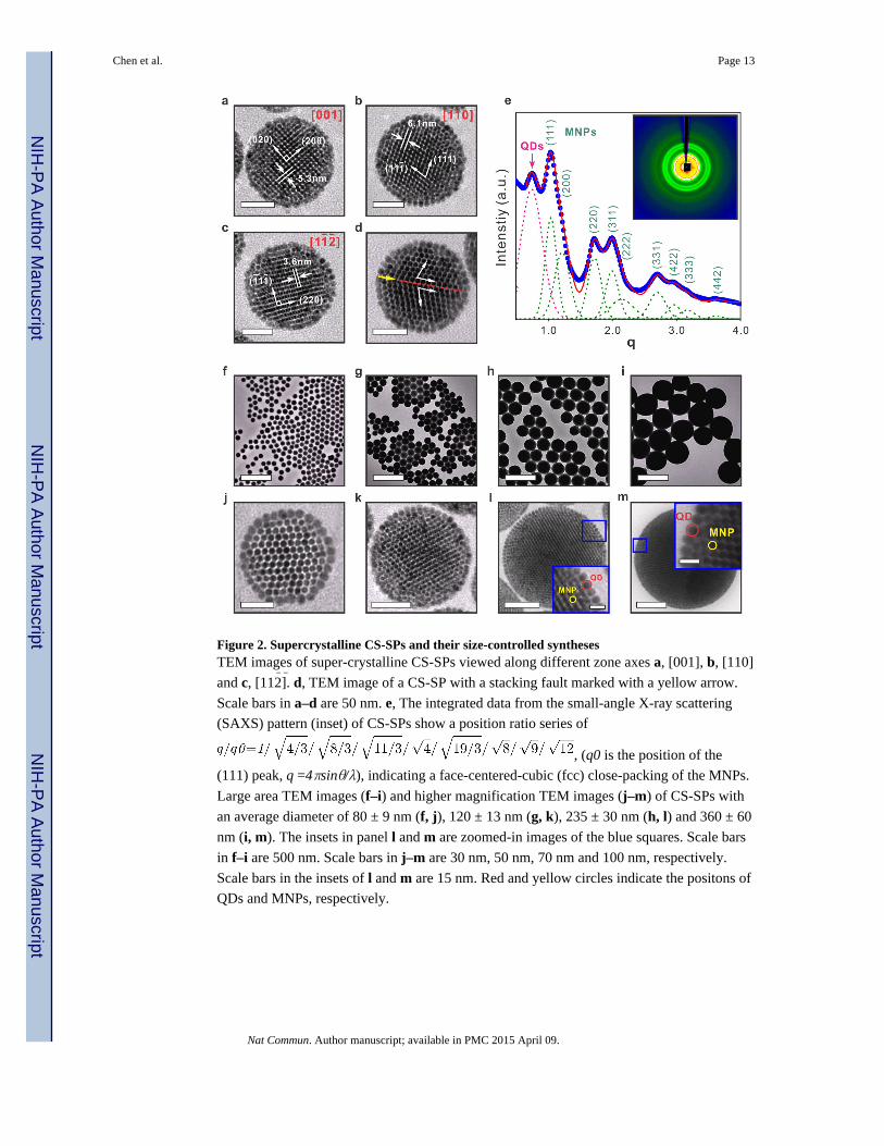
Figure 2. Supercrystalline CS-SPs and their size-controlled synthesesTEM images of super-crystalline CS-SPs viewed along different zone axes a, [001], b, [110]
and c, [11̄2̄]. d, TEM image of a CS-SP with a stacking fault marked with a yellow arrow.
Scale bars in a–d are 50 nm. e, The integrated data from the small-angle X-ray scattering
(SAXS) pattern (inset) of CS-SPs show a position ratio series of
, (q0 is the position of the
(111) peak, q =4πsinθ/λ), indicating a face-centered-cubic (fcc) close-packing of the MNPs.
Large area TEM images (f–i) and higher magnification TEM images (j–m) of CS-SPs with
an average diameter of 80 ± 9 nm (f, j), 120 ± 13 nm (g, k), 235 ± 30 nm (h, l) and 360 ± 60
nm (i, m). The insets in panel l and m are zoomed-in images of the blue squares. Scale bars
in f–i are 500 nm. Scale bars in j–m are 30 nm, 50 nm, 70 nm and 100 nm, respectively.
Scale bars in the insets of l and m are 15 nm. Red and yellow circles indicate the positons of
QDs and MNPs, respectively.
Chen et al. Page 13
Nat Commun. Author manuscript; available in PMC 2015 April 09.
NIH
-PA
Author M
anuscriptN
IH-P
A A
uthor Manuscript
NIH
-PA
Author M
anuscript
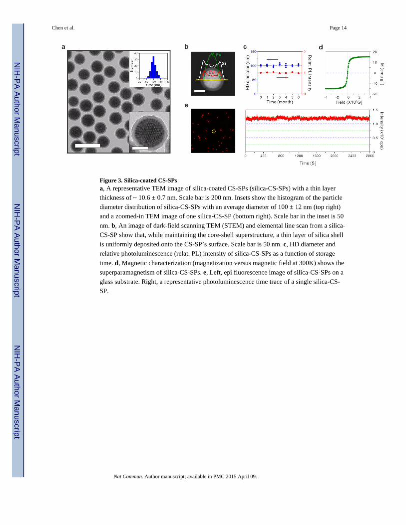
Figure 3. Silica-coated CS-SPsa, A representative TEM image of silica-coated CS-SPs (silica-CS-SPs) with a thin layer
thickness of ~ 10.6 ± 0.7 nm. Scale bar is 200 nm. Insets show the histogram of the particle
diameter distribution of silica-CS-SPs with an average diameter of 100 ± 12 nm (top right)
and a zoomed-in TEM image of one silica-CS-SP (bottom right). Scale bar in the inset is 50
nm. b, An image of dark-field scanning TEM (STEM) and elemental line scan from a silica-
CS-SP show that, while maintaining the core-shell superstructure, a thin layer of silica shell
is uniformly deposited onto the CS-SP’s surface. Scale bar is 50 nm. c, HD diameter and
relative photoluminescence (relat. PL) intensity of silica-CS-SPs as a function of storage
time. d, Magnetic characterization (magnetization versus magnetic field at 300K) shows the
superparamagnetism of silica-CS-SPs. e, Left, epi fluorescence image of silica-CS-SPs on a
glass substrate. Right, a representative photoluminescence time trace of a single silica-CS-
SP.
Chen et al. Page 14
Nat Commun. Author manuscript; available in PMC 2015 April 09.
NIH
-PA
Author M
anuscriptN
IH-P
A A
uthor Manuscript
NIH
-PA
Author M
anuscript
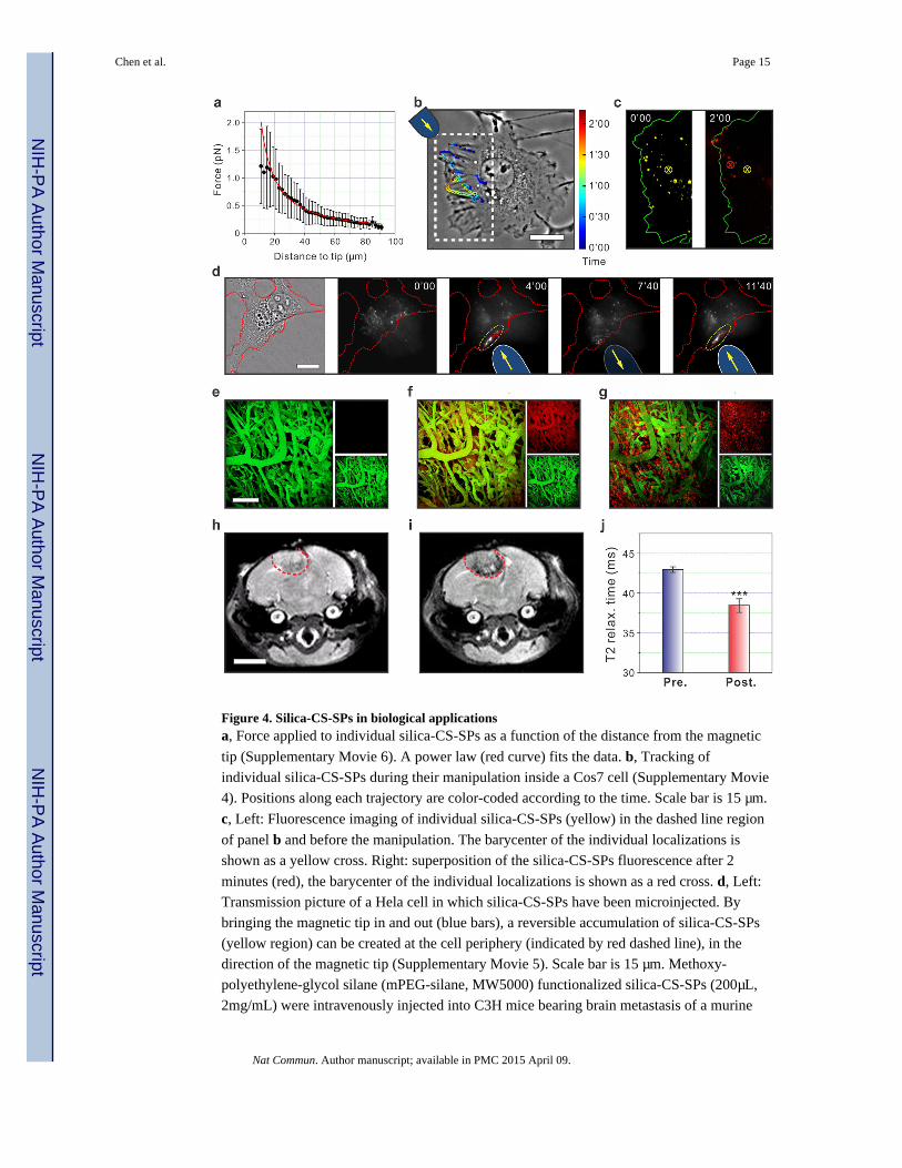
Figure 4. Silica-CS-SPs in biological applicationsa, Force applied to individual silica-CS-SPs as a function of the distance from the magnetic
tip (Supplementary Movie 6). A power law (red curve) fits the data. b, Tracking of
individual silica-CS-SPs during their manipulation inside a Cos7 cell (Supplementary Movie
4). Positions along each trajectory are color-coded according to the time. Scale bar is 15 μm.
c, Left: Fluorescence imaging of individual silica-CS-SPs (yellow) in the dashed line region
of panel b and before the manipulation. The barycenter of the individual localizations is
shown as a yellow cross. Right: superposition of the silica-CS-SPs fluorescence after 2
minutes (red), the barycenter of the individual localizations is shown as a red cross. d, Left:
Transmission picture of a Hela cell in which silica-CS-SPs have been microinjected. By
bringing the magnetic tip in and out (blue bars), a reversible accumulation of silica-CS-SPs
(yellow region) can be created at the cell periphery (indicated by red dashed line), in the
direction of the magnetic tip (Supplementary Movie 5). Scale bar is 15 μm. Methoxy-
polyethylene-glycol silane (mPEG-silane, MW5000) functionalized silica-CS-SPs (200μL,
2mg/mL) were intravenously injected into C3H mice bearing brain metastasis of a murine
Chen et al. Page 15
Nat Commun. Author manuscript; available in PMC 2015 April 09.
NIH
-PA
Author M
anuscriptN
IH-P
A A
uthor Manuscript
NIH
-PA
Author M
anuscript
mammary carcinoma (MCaIV) with a cranial window model. Intravital multiphoton
microscopy through the cranial window was carried out at different time point: pre-injection
(e), 4-hour post-injection (f), and 24-hour post-injection (g). Scale bar is 150 μm. Images
from red and green channels are shown in small panels (top: red channel, bottom: green
channel). Green emission signals are generated from a blood vessel tracer (Fluorescein
isothiocyanate–dextran, FITC-Dextran) and red emission signals are generated by mPEG
functionalized silica-CS-SPs. In vivo T2-weighted magnetic resonance images of pre- (h)
and 24-hour post- (i) injection of mPEG-silane functionalized silica-CS-SPs. 24-hour post-
injection image show clear tumor visualization (denoted by the red-dash line). Scale bar is 3
mm. j, The corresponding T2 relaxation (relax.) time fitting results for the tumor region at
time points of pre-injection (Pre., blue bar) and 24-hour post-injection (Post., red bar). n = 5
mice, *** P < 0.001 (Student’s t test).
Chen et al. Page 16
Nat Commun. Author manuscript; available in PMC 2015 April 09.
NIH
-PA
Author M
anuscriptN
IH-P
A A
uthor Manuscript
NIH
-PA
Author M
anuscript