IQ-unit NEDERLANDS Unité IQ FRANÇAIS ENGLISH · ModBus ... Intelli Air Valve — Duco’s slimme...
112
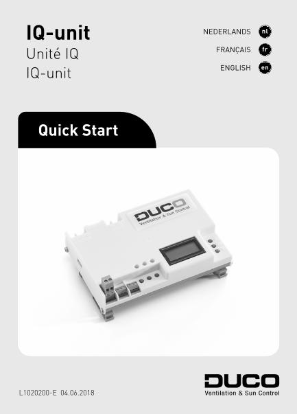
IQ-unit Unité IQ IQ-unit Quick Start L1020200-E 04.06.2018 NEDERLANDS FRANÇAIS ENGLISH
Transcript of IQ-unit NEDERLANDS Unité IQ FRANÇAIS ENGLISH · ModBus ... Intelli Air Valve — Duco’s slimme...
IQ-unitUnité IQIQ-unit
Quick Start
L1020200-E 04.06.2018
NEDERLANDS
FRANÇAIS
ENGLISH
Handelsstraat 19 - 8630 Veurne - Belgium
tel +32 58 33 00 33 - fax +32 58 33 00 44 - [email protected] - www.duco.eu
DUCO, HANDELSSTRAAT 19VEURNE, B-8630
09
Raadpleeg www.duco.eu voor meer informatie omtrent garantie, onderhoud, technische gegevens enz. Installatie, aansluiting, onderhoud en herstellingen dienen door een erkend installateur te gebeuren. De elektronische onderdelen van dit product kunnen onder spanning staan. Vermijd contact met water.
Naviguez vers www.duco.eu pour plus d’informations sur la garantie, l’entretien, des fiches techniques etc. L’installation, le raccordement, l’entretien et les réparations doivent être effectués par un installateur agréé. Les éléments électroniques de ce produit peuvent être sous tension. Éviter tout contact avec l’eau.
See www.duco.eu for information regarding warranty, maintenance, technical data, etc. Installation, connection, maintenance and repairs are to be carried out by an accredited installer. The electronic components of this product may be live. Avoid contact with water.
Nederlands �� � � � � � � � � � � � � � � � � � � � � � � � 3
Français��� � � � � � � � � � � � � � � � � � � � � � � � � � � � 39
English �� � � � � � � � � � � � � � � � � � � � � � � � � � � � � � � 75
3
NEDERLANDS
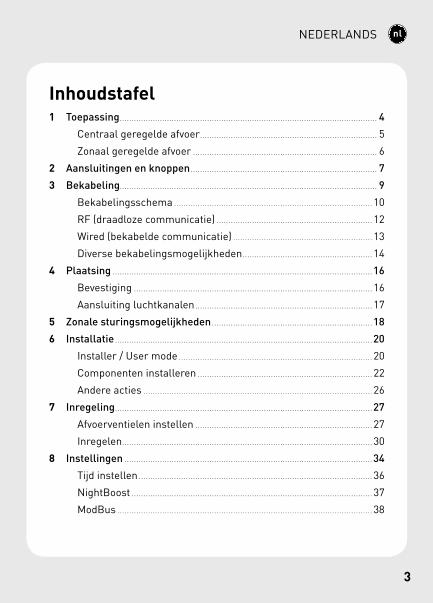
Inhoudstafel1 Toepassing . . . . . . . . . . . . . . . . . . . . . . . . . . . . . . . . . . . . . . . . . . . . . . . . . . . . . . . . . . . . . . . . . . . . . . . . . . . . . . . . . . . . . . . . . . . . . . . . . . . . . . . . . . . . . 4
Centraal geregelde afvoer . . . . . . . . . . . . . . . . . . . . . . . . . . . . . . . . . . . . . . . . . . . . . . . . . . . . . . . . . . . . . . . . . . . . . . . . . . . 5
Zonaal geregelde afvoer . . . . . . . . . . . . . . . . . . . . . . . . . . . . . . . . . . . . . . . . . . . . . . . . . . . . . . . . . . . . . . . . . . . . . . . . . . . . . . 6
2 Aansluitingen en knoppen . . . . . . . . . . . . . . . . . . . . . . . . . . . . . . . . . . . . . . . . . . . . . . . . . . . . . . . . . . . . . . . . . . . . . . . . . . . . . . . 7
3 Bekabeling . . . . . . . . . . . . . . . . . . . . . . . . . . . . . . . . . . . . . . . . . . . . . . . . . . . . . . . . . . . . . . . . . . . . . . . . . . . . . . . . . . . . . . . . . . . . . . . . . . . . . . . . . . . . . 9
Bekabelingsschema .. . . . . . . . . . . . . . . . . . . . . . . . . . . . . . . . . . . . . . . . . . . . . . . . . . . . . . . . . . . . . . . . . . . . . . . . . . . . . . . . . . . 10
RF (draadloze communicatie) . . . . . . . . . . . . . . . . . . . . . . . . . . . . . . . . . . . . . . . . . . . . . . . . . . . . . . . . . . . . . . . . . . 12
Wired (bekabelde communicatie) . . . . . . . . . . . . . . . . . . . . . . . . . . . . . . . . . . . . . . . . . . . . . . . . . . . . . . . . . . . 13
Diverse bekabelingsmogelijkheden .. . . . . . . . . . . . . . . . . . . . . . . . . . . . . . . . . . . . . . . . . . . . . . . . . . . . . . 14
4 Plaatsing . . . . . . . . . . . . . . . . . . . . . . . . . . . . . . . . . . . . . . . . . . . . . . . . . . . . . . . . . . . . . . . . . . . . . . . . . . . . . . . . . . . . . . . . . . . . . . . . . . . . . . . . . . . . . . 16
Bevestiging .. . . . . . . . . . . . . . . . . . . . . . . . . . . . . . . . . . . . . . . . . . . . . . . . . . . . . . . . . . . . . . . . . . . . . . . . . . . . . . . . . . . . . . . . . . . . . . . . . . . . 16
Aansluiting luchtkanalen .. . . . . . . . . . . . . . . . . . . . . . . . . . . . . . . . . . . . . . . . . . . . . . . . . . . . . . . . . . . . . . . . . . . . . . . . . . 17
5 Zonale sturingsmogelijkheden . . . . . . . . . . . . . . . . . . . . . . . . . . . . . . . . . . . . . . . . . . . . . . . . . . . . . . . . . . . . . . . . . . . . 18
6 Installatie . . . . . . . . . . . . . . . . . . . . . . . . . . . . . . . . . . . . . . . . . . . . . . . . . . . . . . . . . . . . . . . . . . . . . . . . . . . . . . . . . . . . . . . . . . . . . . . . . . . . . . . . . . . . . 20
Installer / User mode .. . . . . . . . . . . . . . . . . . . . . . . . . . . . . . . . . . . . . . . . . . . . . . . . . . . . . . . . . . . . . . . . . . . . . . . . . . . . . . . . . 20
Componenten installeren .. . . . . . . . . . . . . . . . . . . . . . . . . . . . . . . . . . . . . . . . . . . . . . . . . . . . . . . . . . . . . . . . . . . . . . . . . 22
Andere acties . . . . . . . . . . . . . . . . . . . . . . . . . . . . . . . . . . . . . . . . . . . . . . . . . . . . . . . . . . . . . . . . . . . . . . . . . . . . . . . . . . . . . . . . . . . . . . . . . 26
7 Inregeling . . . . . . . . . . . . . . . . . . . . . . . . . . . . . . . . . . . . . . . . . . . . . . . . . . . . . . . . . . . . . . . . . . . . . . . . . . . . . . . . . . . . . . . . . . . . . . . . . . . . . . . . . . . . . 27
Afvoerventielen instellen .. . . . . . . . . . . . . . . . . . . . . . . . . . . . . . . . . . . . . . . . . . . . . . . . . . . . . . . . . . . . . . . . . . . . . . . . . . 27
Inregelen .. . . . . . . . . . . . . . . . . . . . . . . . . . . . . . . . . . . . . . . . . . . . . . . . . . . . . . . . . . . . . . . . . . . . . . . . . . . . . . . . . . . . . . . . . . . . . . . . . . . . . . . . . 30
8 Instellingen . . . . . . . . . . . . . . . . . . . . . . . . . . . . . . . . . . . . . . . . . . . . . . . . . . . . . . . . . . . . . . . . . . . . . . . . . . . . . . . . . . . . . . . . . . . . . . . . . . . . . . . . . 34
Tijd instellen .. . . . . . . . . . . . . . . . . . . . . . . . . . . . . . . . . . . . . . . . . . . . . . . . . . . . . . . . . . . . . . . . . . . . . . . . . . . . . . . . . . . . . . . . . . . . . . . . . . 36
NightBoost . . . . . . . . . . . . . . . . . . . . . . . . . . . . . . . . . . . . . . . . . . . . . . . . . . . . . . . . . . . . . . . . . . . . . . . . . . . . . . . . . . . . . . . . . . . . . . . . . . . . . . 37
ModBus .. . . . . . . . . . . . . . . . . . . . . . . . . . . . . . . . . . . . . . . . . . . . . . . . . . . . . . . . . . . . . . . . . . . . . . . . . . . . . . . . . . . . . . . . . . . . . . . . . . . . . . . . . . . 38
Nederlands
4
NEDERLANDS
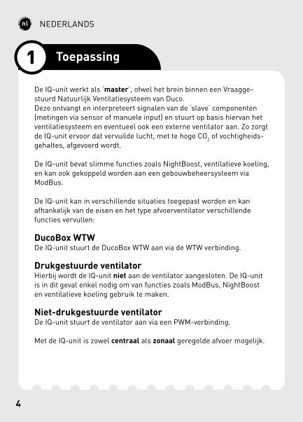
De IQ-unit werkt als ‘master’, ofwel het brein binnen een Vraagge-stuurd Natuurlijk Ventilatiesysteem van Duco.Deze ontvangt en interpreteert signalen van de ‘slave’ componenten (metingen via sensor of manuele input) en stuurt op basis hiervan het ventilatiesysteem en eventueel ook een externe ventilator aan. Zo zorgt de IQ-unit ervoor dat vervuilde lucht, met te hoge CO2 of vochtigheids-gehaltes, afgevoerd wordt.
De IQ-unit bevat slimme functies zoals NightBoost, ventilatieve koeling, en kan ook gekoppeld worden aan een gebouwbeheersysteem via ModBus.
De IQ-unit kan in verschillende situaties toegepast worden en kan afhankelijk van de eisen en het type afvoerventilator verschillende functies vervullen:
DucoBox WTWDe IQ-unit stuurt de DucoBox WTW aan via de WTW verbinding.
Drukgestuurde ventilatorHierbij wordt de IQ-unit niet aan de ventilator aangesloten. De IQ-unit is in dit geval enkel nodig om van functies zoals ModBus, NightBoost en ventilatieve koeling gebruik te maken.
Niet-drukgestuurde ventilatorDe IQ-unit stuurt de ventilator aan via een PWM-verbinding.
Met de IQ-unit is zowel centraal als zonaal geregelde afvoer mogelijk.
1 Toepassing
5
NEDERLANDS
*PWM
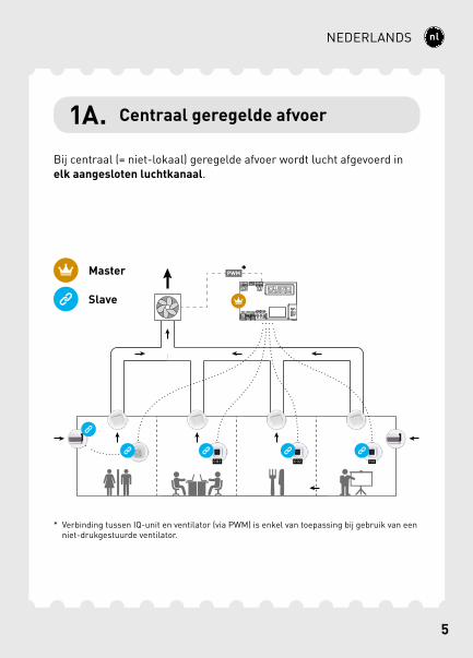
Bij centraal (= niet-lokaal) geregelde afvoer wordt lucht afgevoerd in elk aangesloten luchtkanaal.
1A. Centraal geregelde afvoer
Master
Slave
* Verbinding tussen IQ-unit en ventilator (via PWM) is enkel van toepassing bij gebruik van een niet-drukgestuurde ventilator.
6
NEDERLANDS
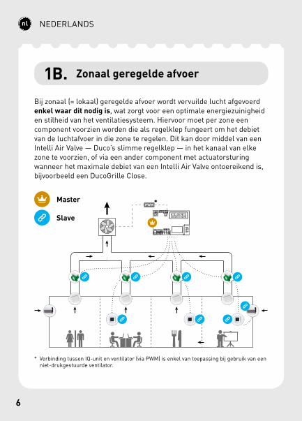
1B. Zonaal geregelde afvoer
Bij zonaal (= lokaal) geregelde afvoer wordt vervuilde lucht afgevoerd enkel waar dit nodig is, wat zorgt voor een optimale energiezuinigheid en stilheid van het ventilatiesysteem. Hiervoor moet per zone een component voorzien worden die als regelklep fungeert om het debiet van de luchtafvoer in die zone te regelen. Dit kan door middel van een Intelli Air Valve — Duco’s slimme regelklep — in het kanaal van elke zone te voorzien, of via een ander component met actuatorsturing wanneer het maximale debiet van een Intelli Air Valve ontoereikend is, bijvoorbeeld een DucoGrille Close.
PWM*Master
Slave
* Verbinding tussen IQ-unit en ventilator (via PWM) is enkel van toepassing bij gebruik van een niet-drukgestuurde ventilator.

7
NEDERLANDS
4
1
5
2
6
3
10
7
A
8
B
C
FE
D
119
A
A
B
B
GND
GND
- +
- +
- +
2 Aansluitingen en knoppen
8
NEDERLANDS
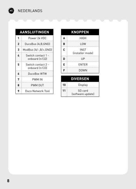
AANSLUITINGEN1 Power 24 VDC
2 DucoBus (A,B,GND)
3 ModBus (A/-,B/+,GND)
4 Switch contact 1 - onboard (n132)
5 Switch contact 2 - onboard (n133)
6 DucoBox WTW
7 PWM IN
8 PWM OUT
9 Duco Network Tool
KNOPPENA HIGH
B LOW
C INST(installer mode)
D UP
E ENTER
F DOWN
DIVERSEN10 Display
11 SD card (software update)

8 9
NEDERLANDS
De IQ-unit kan zowel via een draadloze (RF) of bedrade (Wired) verbin-ding communiceren met ‘slave’ componenten. Beide communicatie-types kunnen gecombineerd worden in één systeem. In utiliteits- en andere projecten waar grote afstanden of verschillende muren en/of bouwlagen overbrugd moeten worden zijn Wired-verbindingen steeds aangeraden.
Daarnaast zijn aansluitingen via een Schakelcontact (2 stuks), PWM-IN en PWM-UIT, WTW en ModBus mogelijk.
3 Bekabeling
10
NEDERLANDS
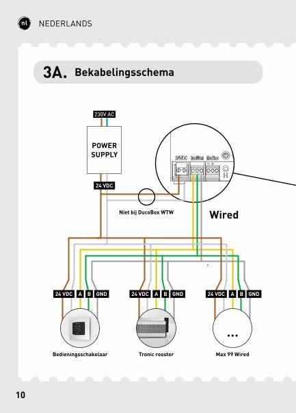
Wired
24 VDC
24 VDC
A B GND
POWER SUPPLY
Bedieningsschakelaar Tronic rooster
24 VDC A B GND 24 VDC A B GND
Niet bij DucoBox WTW
Max 99 Wired
3A. Bekabelingsschema
10 11
NEDERLANDS
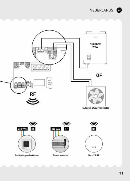
Max 25 RF
RF230 VAC
Bedieningsschakelaar
RF230 VAC
Tronic rooster
DUCOBOX WTW
Externe afvoerventilator
OF
RF
RF
12
NEDERLANDS
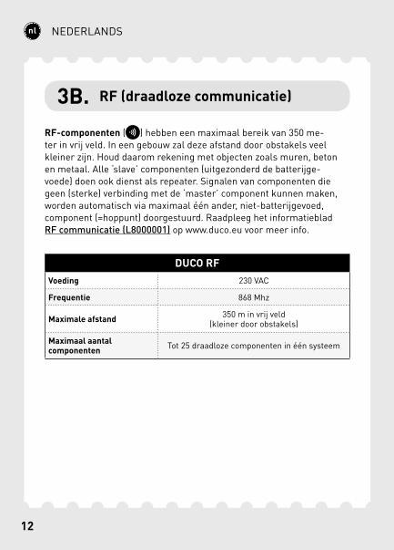
3B. RF (draadloze communicatie)
RF-componenten ( ) hebben een maximaal bereik van 350 me-ter in vrij veld. In een gebouw zal deze afstand door obstakels veel kleiner zijn. Houd daarom rekening met objecten zoals muren, beton en metaal. Alle ‘slave’ componenten (uitgezonderd de batterijge-voede) doen ook dienst als repeater. Signalen van componenten die geen (sterke) verbinding met de ‘master’ component kunnen maken, worden automatisch via maximaal één ander, niet-batterijgevoed, component (=hoppunt) doorgestuurd. Raadpleeg het informatieblad RF communicatie (L8000001) op www.duco.eu voor meer info.
DUCO RFVoeding 230 VAC
Frequentie 868 Mhz
Maximale afstand 350 m in vrij veld (kleiner door obstakels)
Maximaal aantal componenten Tot 25 draadloze componenten in één systeem
12 13
NEDERLANDS
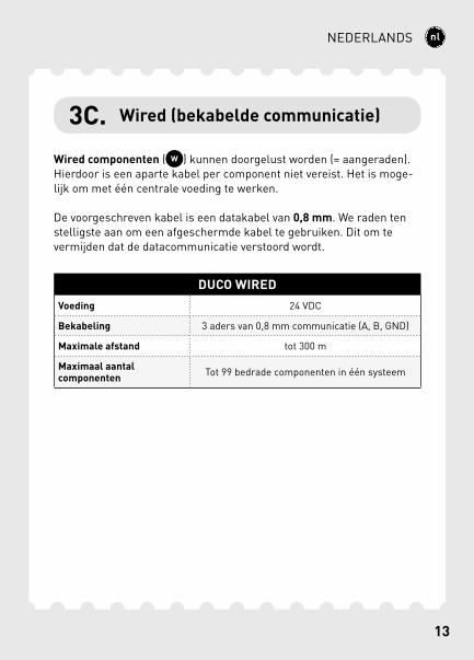
3C. Wired (bekabelde communicatie)
Wired componenten ( ) kunnen doorgelust worden (= aangeraden). Hierdoor is een aparte kabel per component niet vereist. Het is moge-lijk om met één centrale voeding te werken.
De voorgeschreven kabel is een datakabel van 0,8 mm. We raden ten stelligste aan om een afgeschermde kabel te gebruiken. Dit om te vermijden dat de datacommunicatie verstoord wordt.
DUCO WIREDVoeding 24 VDC
Bekabeling 3 aders van 0,8 mm communicatie (A, B, GND)
Maximale afstand tot 300 m
Maximaal aantal componenten Tot 99 bedrade componenten in één systeem
14
NEDERLANDS
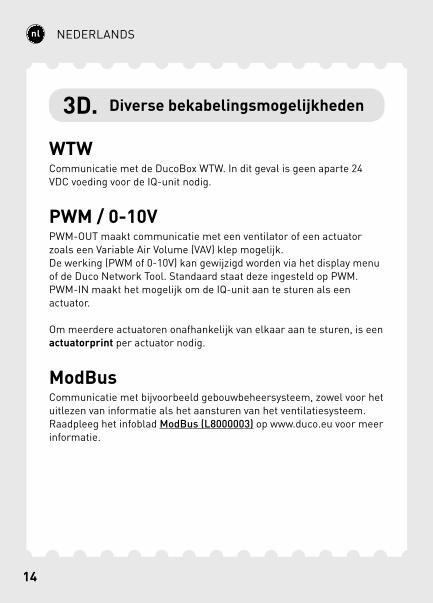
3D. Diverse bekabelingsmogelijkheden
WTWCommunicatie met de DucoBox WTW. In dit geval is geen aparte 24 VDC voeding voor de IQ-unit nodig.
PWM / 0-10VPWM-OUT maakt communicatie met een ventilator of een actuator zoals een Variable Air Volume (VAV) klep mogelijk.De werking (PWM of 0-10V) kan gewijzigd worden via het display menu of de Duco Network Tool. Standaard staat deze ingesteld op PWM.PWM-IN maakt het mogelijk om de IQ-unit aan te sturen als een actuator.
Om meerdere actuatoren onafhankelijk van elkaar aan te sturen, is een actuatorprint per actuator nodig.
ModBusCommunicatie met bijvoorbeeld gebouwbeheersysteem, zowel voor het uitlezen van informatie als het aansturen van het ventilatiesysteem. Raadpleeg het infoblad ModBus (L8000003) op www.duco.eu voor meer informatie.
14 15
NEDERLANDS
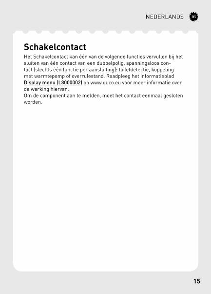
SchakelcontactHet Schakelcontact kan één van de volgende functies vervullen bij het sluiten van één contact van een dubbelpolig, spanningsloos con-tact (slechts één functie per aansluiting): toiletdetectie, koppeling met warmtepomp of overrule stand. Raadpleeg het informatieblad Display menu (L8000002) op www.duco.eu voor meer informatie over de werking hiervan.Om de component aan te melden, moet het contact eenmaal gesloten worden.
16
NEDERLANDS
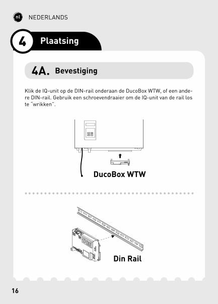
Klik de IQ-unit op de DIN-rail onderaan de DucoBox WTW, of een ande-re DIN-rail. Gebruik een schroevendraaier om de IQ-unit van de rail los te “wrikken”.
Din Rail
DucoBox WTW
4 Plaatsing
4A. Bevestiging
16 17
NEDERLANDS
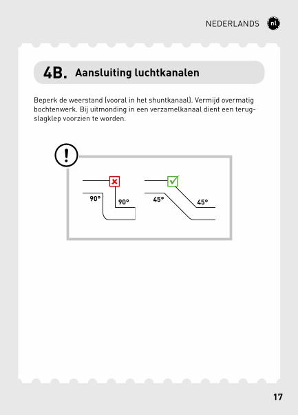
4B. Aansluiting luchtkanalen
Beperk de weerstand (vooral in het shuntkanaal). Vermijd overmatig bochtenwerk. Bij uitmonding in een verzamelkanaal dient een terug-slagklep voorzien te worden.
18
NEDERLANDS
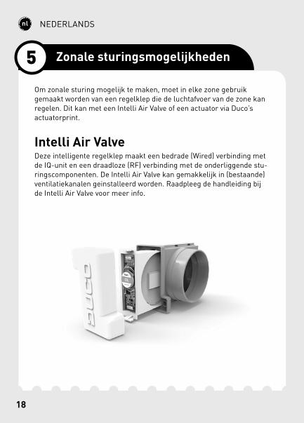
Om zonale sturing mogelijk te maken, moet in elke zone gebruik gemaakt worden van een regelklep die de luchtafvoer van de zone kan regelen. Dit kan met een Intelli Air Valve of een actuator via Duco’s actuatorprint.
Intelli Air ValveDeze intelligente regelklep maakt een bedrade (Wired) verbinding met de IQ-unit en een draadloze (RF) verbinding met de onderliggende stu-ringscomponenten. De Intelli Air Valve kan gemakkelijk in (bestaande) ventilatiekanalen geinstalleerd worden. Raadpleeg de handleiding bij de Intelli Air Valve voor meer info.
5 Zonale sturingsmogelijkheden
18 19
NEDERLANDS
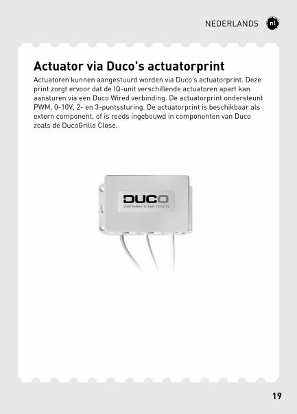
Actuator via Duco's actuatorprintActuatoren kunnen aangestuurd worden via Duco’s actuatorprint. Deze print zorgt ervoor dat de IQ-unit verschillende actuatoren apart kan aansturen via een Duco Wired verbinding. De actuatorprint ondersteunt PWM, 0-10V, 2- en 3-puntssturing. De actuatorprint is beschikbaar als extern component, of is reeds ingebouwd in componenten van Duco zoals de DucoGrille Close.
20
NEDERLANDS
Om componenten aan het netwerk toe te voegen, te verwijderen of te vervangen, dient het systeem in ‘Installer mode’ gezet te worden. De LED op elke component duidt de actieve modus van de component aan (zie onderstaande tabel).
‘Installer mode’ kan geactiveerd worden door de ‘INST’ knop van de IQ-unit in te drukken. Wanneer de LED op de master unit begint te knipperen, is ‘Installer mode’ actief. Druk nogmaals op ‘INST’ om terug naar ‘User mode’ te keren (LED volledig aan of uit). Na 15 minuten inactiviteit keert het systeem automatisch terug naar ‘User mode’.
6 Installatie
6A. Installer / User mode

20 21
NEDERLANDS
LED-INDICATIE
ROOD (traag knipperen) Niet in netwerk
ROOD (snel knipperen) Bezig met aanmelden
GROEN (traag knipperen) In netwerk
GROEN (snel knipperen) In netwerk, wachtend op geassocieerde componenten
GEEL (traag knipperen) Overgangsfase (a.u.b. wachten)
GEEL (aan) Initialisatie
(inregeling van het systeem bezig)
WIT of UIT Normaal
22
NEDERLANDS
6B. Componenten installeren
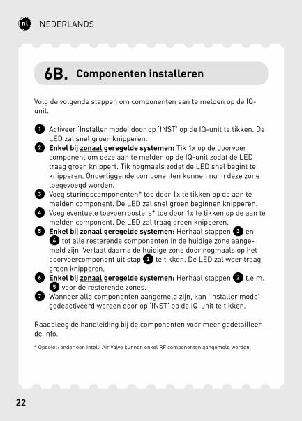
Volg de volgende stappen om componenten aan te melden op de IQ-unit.
1 Activeer ‘Installer mode’ door op ‘INST’ op de IQ-unit te tikken. De LED zal snel groen knipperen.
2 Enkel bij zonaal geregelde systemen: Tik 1x op de doorvoer component om deze aan te melden op de IQ-unit zodat de LED traag groen knippert. Tik nogmaals zodat de LED snel begint te knipperen. Onderliggende componenten kunnen nu in deze zone toegevoegd worden.
3 Voeg sturingscomponenten* toe door 1x te tikken op de aan te melden component. De LED zal snel groen beginnen knipperen.
4 Voeg eventuele toevoerroosters* toe door 1x te tikken op de aan te melden component. De LED zal traag groen knipperen.
5 Enkel bij zonaal geregelde systemen: Herhaal stappen 3 en 4 tot alle resterende componenten in de huidige zone aange-
meld zijn. Verlaat daarna de huidige zone door nogmaals op het doorvoercomponent uit stap 2 te tikken. De LED zal weer traag groen knipperen.
6 Enkel bij zonaal geregelde systemen: Herhaal stappen 2 t.e.m. 5 voor de resterende zones.
7 Wanneer alle componenten aangemeld zijn, kan ‘Installer mode’ gedeactiveerd worden door op ‘INST’ op de IQ-unit te tikken.
Raadpleeg de handleiding bij de componenten voor meer gedetailleer-de info.
* Opgelet: onder een Intelli Air Valve kunnen enkel RF componenten aangemeld worden.

22 23
NEDERLANDS
4
2
3
1 7
5
6
24
NEDERLANDS
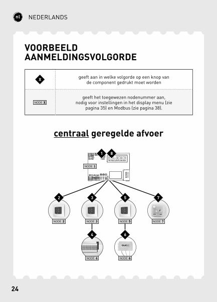
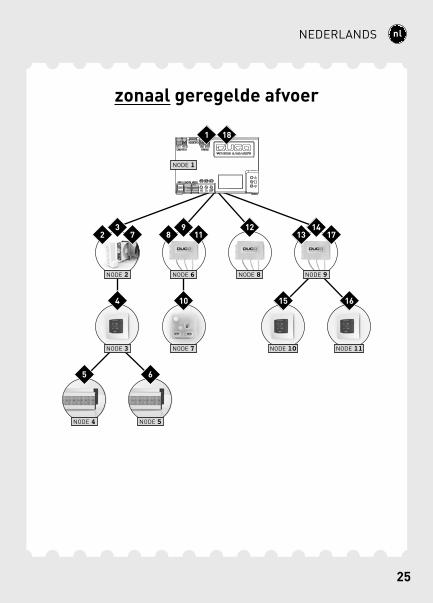
VOORBEELD AANMELDINGSVOLGORDE
centraal geregelde afvoer
NODE 2 NODE 3 NODE 5 NODE 7
NODE 4 NODE 6
NODE 1
1
2 3
4
5
6
7
8
X geeft aan in welke volgorde op een knop van de component gedrukt moet worden
NODE Xgeeft het toegewezen nodenummer aan,
nodig voor instellingen in het display menu (zie pagina 35) en Modbus (zie pagina 38).
24 25
NEDERLANDS
zonaal geregelde afvoer
NODE 1
NODE 2 NODE 6 NODE 8 NODE 9
NODE 3 NODE 7
NODE 4 NODE 5
NODE 10 NODE 11
1
92
10
311
4
12
5
13
6
147
15
8
16
17
18
26
NEDERLANDS
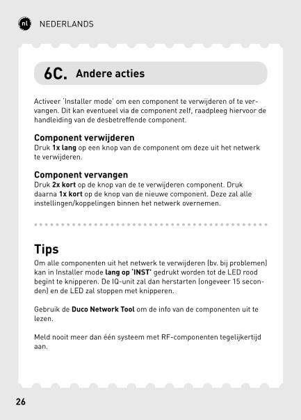
6C. Andere acties
Activeer ‘Installer mode’ om een component te verwijderen of te ver-vangen. Dit kan eventueel via de component zelf, raadpleeg hiervoor de handleiding van de desbetreffende component.
Component verwijderenDruk 1x lang op een knop van de component om deze uit het netwerk te verwijderen.
Component vervangenDruk 2x kort op de knop van de te verwijderen component. Druk daarna 1x kort op de knop van de nieuwe component. Deze zal alle instellingen/koppelingen binnen het netwerk overnemen.
TipsOm alle componenten uit het netwerk te verwijderen (bv. bij problemen) kan in Installer mode lang op ‘INST’ gedrukt worden tot de LED rood begint te knipperen. De IQ-unit zal dan herstarten (ongeveer 15 secon-den) en de LED zal stoppen met knipperen.
Gebruik de Duco Network Tool om de info van de componenten uit te lezen.
Meld nooit meer dan één systeem met RF-componenten tegelijkertijd aan.
26 27
NEDERLANDS
Voor een correcte werking van het systeem moet deze ingeregeld wor-den. Dit zorgt ook voor een zo stil en energiezuinig mogelijke werking.
Voor info over het bepalen van de ventilatiedebieten, kijk onder de rubriek Tools op www.duco.eu.
De inregeling gebeurt in twee fases: afvoerventielen instellen en effec-tieve inregeling.
De afvoerventielen worden in een afvoerkanaal geplaatst voor de afzui-ging van vochtige/vervuilde lucht. Voor een correcte inregeling moeten de ventielen ingesteld worden afhankelijk van de afvoermethode:Centrale afvoer: stel de ventielen zo in dat ze overeenkomen met het gewenste debiet volgens de volgende tabel.Zonale afvoer: stel de ventielen in volgens de hierna volgende metho-des, afhankelijk van de situatie per zone.
Laat bij gebruik van DucoVent Design ventielen steeds de buitenste ring zitten voor een akoestische werking.
7 Inregeling
7A. Afvoerventielen instellen

28
NEDERLANDS
DUCOVENT DESIGN
DUCOVENT BASICEN ANDERE VENTIELEN
75m3/h 100% open
50m3/h 50% open
25m3/h 25% open
Mousse
28 29
NEDERLANDS
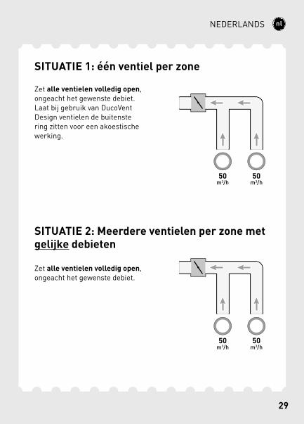
SITUATIE 1: één ventiel per zone
Zet alle ventielen volledig open, ongeacht het gewenste debiet. Laat bij gebruik van DucoVent Design ventielen de buitenste ring zitten voor een akoestische werking.
SITUATIE 2: Meerdere ventielen per zone met gelijke debieten
Zet alle ventielen volledig open, ongeacht het gewenste debiet.
30
NEDERLANDS
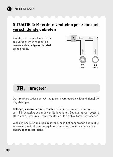
SITUATIE 3: Meerdere ventielen per zone met verschillende debieten
Stel de afvoerventielen zo in dat ze overeenkomen met het ge-wenste debiet volgens de tabel op pagina 28.
7B. Inregelen
De inregelprocedure omvat het gebruik van meerdere (stand alone) iAV Regelkleppen.
Belangrijk vooraleer in te regelen: Sluit alle ramen en deuren en vermijd luchtlekkages in de ventilatiekanalen. Zet alle toevoerroosters 100% open. Eventuele Tronic roosters zullen zich automatisch openen.
Voor een snelle en makkelijke inregeling is het aangeraden om in elke zone een constant volumeregelaar te voorzien (debiet = som van de onderliggende debieten).

30 31
NEDERLANDS
PWM
2
3
4
49
5a5b
6
7
8b8b
1
75 m³/h50 m³/h25 m³/h
75 m³/h50 m³/h25 m³/h
150 m³/h
150 m³/h
Zone 2
Zone 1
Constant volume regelaar
32
NEDERLANDS
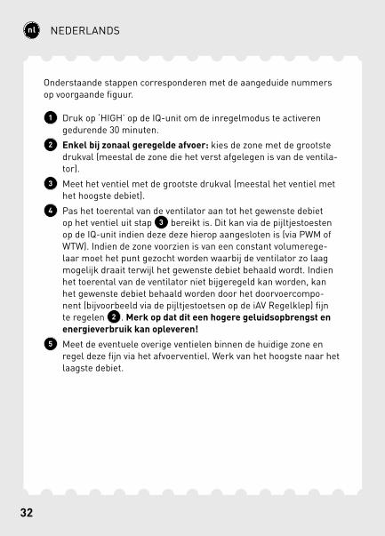
Onderstaande stappen corresponderen met de aangeduide nummers op voorgaande figuur.
1 Druk op ‘HIGH’ op de IQ-unit om de inregelmodus te activeren gedurende 30 minuten.
2 Enkel bij zonaal geregelde afvoer: kies de zone met de grootste drukval (meestal de zone die het verst afgelegen is van de ventila-tor).
3 Meet het ventiel met de grootste drukval (meestal het ventiel met het hoogste debiet).
4 Pas het toerental van de ventilator aan tot het gewenste debiet op het ventiel uit stap 3 bereikt is. Dit kan via de pijltjestoesten op de IQ-unit indien deze deze hierop aangesloten is (via PWM of WTW). Indien de zone voorzien is van een constant volumerege-laar moet het punt gezocht worden waarbij de ventilator zo laag mogelijk draait terwijl het gewenste debiet behaald wordt. Indien het toerental van de ventilator niet bijgeregeld kan worden, kan het gewenste debiet behaald worden door het doorvoercompo-nent (bijvoorbeeld via de pijltjestoetsen op de iAV Regelklep) fijn te regelen 2 . Merk op dat dit een hogere geluidsopbrengst en energieverbruik kan opleveren!
5 Meet de eventuele overige ventielen binnen de huidige zone en regel deze fijn via het afvoerventiel. Werk van het hoogste naar het laagste debiet.
32 33
NEDERLANDS
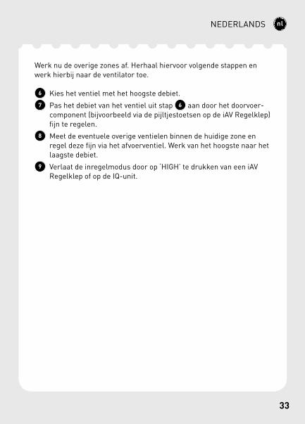
Werk nu de overige zones af. Herhaal hiervoor volgende stappen en werk hierbij naar de ventilator toe.
6 Kies het ventiel met het hoogste debiet.7 Pas het debiet van het ventiel uit stap 6 aan door het doorvoer-
component (bijvoorbeeld via de pijltjestoetsen op de iAV Regelklep) fijn te regelen.
8 Meet de eventuele overige ventielen binnen de huidige zone en regel deze fijn via het afvoerventiel. Werk van het hoogste naar het laagste debiet.
9 Verlaat de inregelmodus door op ‘HIGH’ te drukken van een iAV Regelklep of op de IQ-unit.
34
NEDERLANDS
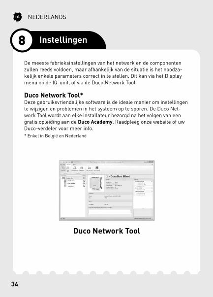
De meeste fabrieksinstellingen van het netwerk en de componenten zullen reeds voldoen, maar afhankelijk van de situatie is het noodza-kelijk enkele parameters correct in te stellen. Dit kan via het Display menu op de IQ-unit, of via de Duco Network Tool.
Duco Network Tool*Deze gebruiksvriendelijke software is de ideale manier om instellingen te wijzigen en problemen in het systeem op te sporen. De Duco Net-work Tool wordt aan elke installateur bezorgd na het volgen van een gratis opleiding aan de Duco Academy. Raadpleeg onze website of uw Duco-verdeler voor meer info.* Enkel in België en Nederland
Duco Network Tool
8 Instellingen
34 35
NEDERLANDS
DISPLAYMENU
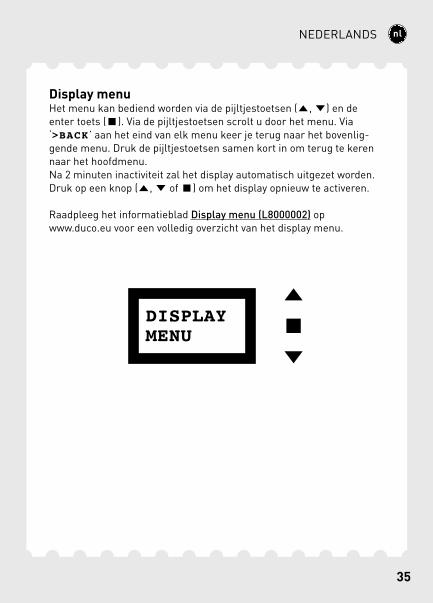
Display menuHet menu kan bediend worden via de pijltjestoetsen ( , ) en de enter toets ( ). Via de pijltjestoetsen scrolt u door het menu. Via ‘>BACK ’ aan het eind van elk menu keer je terug naar het bovenlig-gende menu. Druk de pijltjestoetsen samen kort in om terug te keren naar het hoofdmenu.Na 2 minuten inactiviteit zal het display automatisch uitgezet worden. Druk op een knop ( , of ) om het display opnieuw te activeren.
Raadpleeg het informatieblad Display menu (L8000002) op www.duco.eu voor een volledig overzicht van het display menu.
36
NEDERLANDS
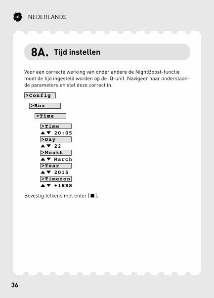
8A. Tijd instellen
Voor een correcte werking van onder andere de NightBoost-functie moet de tijd ingesteld worden op de IQ-unit. Navigeer naar onderstaan-de parameters en stel deze correct in:
>Config
>Box
>Time
>Time 20:05 >Day 22 >Month March >Year 2015 >Timezon +1HRS
Bevestig telkens met enter ( ).
36 37
NEDERLANDS
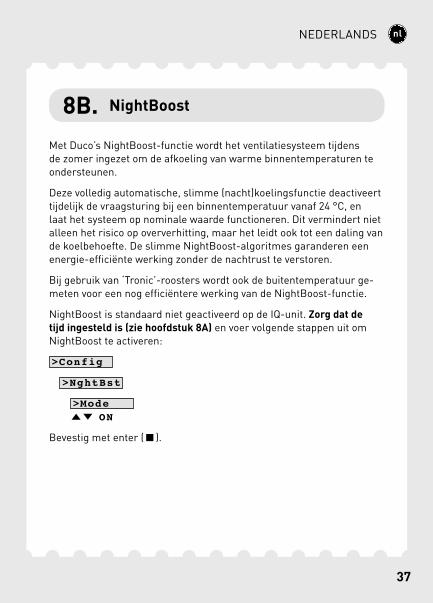
8B. NightBoost
Met Duco’s NightBoost-functie wordt het ventilatiesysteem tijdens de zomer ingezet om de afkoeling van warme binnentemperaturen te ondersteunen.
Deze volledig automatische, slimme (nacht)koelingsfunctie deactiveert tijdelijk de vraagsturing bij een binnentemperatuur vanaf 24 °C, en laat het systeem op nominale waarde functioneren. Dit vermindert niet alleen het risico op oververhitting, maar het leidt ook tot een daling van de koelbehoefte. De slimme NightBoost-algoritmes garanderen een energie-efficiënte werking zonder de nachtrust te verstoren.
Bij gebruik van ‘Tronic’-roosters wordt ook de buitentemperatuur ge-meten voor een nog efficiëntere werking van de NightBoost-functie.
NightBoost is standaard niet geactiveerd op de IQ-unit. Zorg dat de tijd ingesteld is (zie hoofdstuk 8A) en voer volgende stappen uit om NightBoost te activeren:
>Config
>NghtBst
>Mode ON
Bevestig met enter ( ).
38
NEDERLANDS
8C. ModBus
Via een ModBus-verbinding is het mogelijk om vanaf gekoppelde apparatuur (vb: gebouwbeheersysteem) parameters van het ventila-tiesysteem uit te lezen en te wijzigen. Raadpleeg het informatieblad ModBus (L8000003) op www.duco.eu voor uitgebreide informatie over ModBus.
39
FRANÇAIS
Français
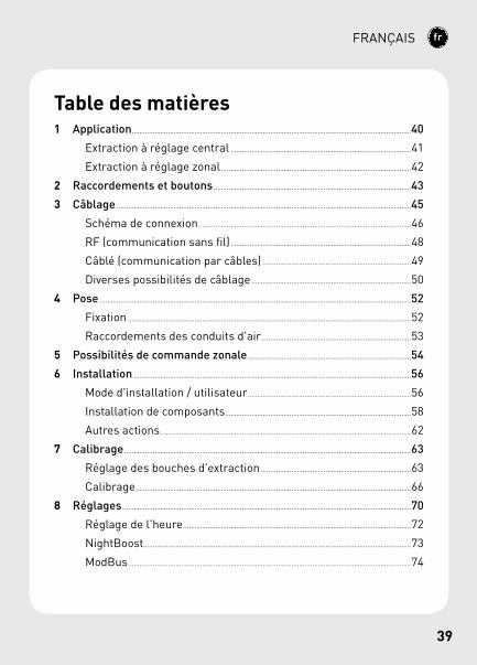
Table des matières1 Application ...................................................................................................................................................40
Extraction à réglage central ...............................................................................................41
Extraction à réglage zonal ....................................................................................................42
2 Raccordements et boutons ........................................................................................................43
3 Câblage ...........................................................................................................................................................45
Schéma de connexion ................................................................................................................46
RF (communication sans fil) ...............................................................................................48
Câblé (communication par câbles) ..............................................................................49
Diverses possibilités de câblage ....................................................................................50
4 Pose ....................................................................................................................................................................52
Fixation .....................................................................................................................................................52
Raccordements des conduits d'air ...............................................................................53
5 Possibilités de commande zonale ......................................................................................54
6 Installation ..................................................................................................................................................56
Mode d'installation / utilisateur ......................................................................................56
Installation de composants ..................................................................................................58
Autres actions ....................................................................................................................................62
7 Calibrage .......................................................................................................................................................63
Réglage des bouches d'extraction ...............................................................................63
Calibrage .................................................................................................................................................66
8 Réglages ........................................................................................................................................................70
Réglage de l'heure ........................................................................................................................72
NightBoost.............................................................................................................................................73
ModBus .....................................................................................................................................................74
40
FRANÇAIS
L'Unité IQ sert de « maître » dans un Système de ventilation Naturelle à la Demande Duco.Elle reçoit et interprète les signaux provenant des composants « es-claves » (mesures via capteur ou saisie manuelle). Sur cette base, elle commande le système de ventilation et éventuellement aussi un ventilateur externe. L'Unité IQ assure ainsi l'extraction de l'air vicié par des niveaux de CO2 ou d'humidité trop élevés.
L'Unité IQ est dotée de fonctions intelligentes comme NightBoost et le rafraîchissement par ventilation, et peut également être couplée à un système de gestion technique de bâtiment via ModBus.
L'Unité IQ peut être utilisée dans différentes situations et remplir di-verses fonctions selon les exigences et le type de ventilateur d'extrac-tion.
DucoBox WTWL'Unité IQ commande le DucoBox WTW via la connexion WTW.
Ventilateur commandé par la pressionIci, l'Unité IQ n'est pas raccordée au ventilateur. Elle n'est nécessaire dans ce cas que pour permettre l'utilisation de fonctions telles que ModBus, NightBoost et rafraîchissement par ventilation.
Ventilateur non commandé par la pressionL'Unité IQ commande le ventilateur via une connexion PWM.
L'Unité IQ permet une extraction à réglage central et zonal.
1 Application
41
FRANÇAIS
*PWM
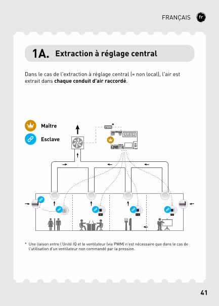
Dans le cas de l'extraction à réglage central (= non local), l'air est extrait dans chaque conduit d'air raccordé.
1A. Extraction à réglage central
Maître
Esclave
* Une liaison entre l'Unité IQ et le ventilateur (via PWM) n'est nécessaire que dans le cas de l'utilisation d'un ventilateur non commandé par la pression.
42
FRANÇAIS
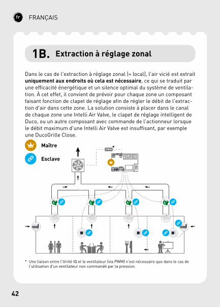
1B. Extraction à réglage zonal
Dans le cas de l'extraction à réglage zonal (= local), l'air vicié est extrait uniquement aux endroits où cela est nécessaire, ce qui se traduit par une efficacité énergétique et un silence optimal du système de ventila-tion. À cet effet, il convient de prévoir pour chaque zone un composant faisant fonction de clapet de réglage afin de régler le débit de l'extrac-tion d'air dans cette zone. La solution consiste à placer dans le canal de chaque zone une Intelli Air Valve, le clapet de réglage intelligent de Duco, ou un autre composant avec commande de l'actionneur lorsque le débit maximum d'une Intelli Air Valve est insuffisant, par exemple une DucoGrille Close.
PWM*Maître
Esclave
* Une liaison entre l'Unité IQ et le ventilateur (via PWM) n'est nécessaire que dans le cas de l'utilisation d'un ventilateur non commandé par la pression.
43
FRANÇAIS
4
1
5
2
6
3
10
7
A
8
B
C
FE
D
119
A
A
B
B
GND
GND
- +
- +
- +
2 Raccordements et boutons
44
FRANÇAIS
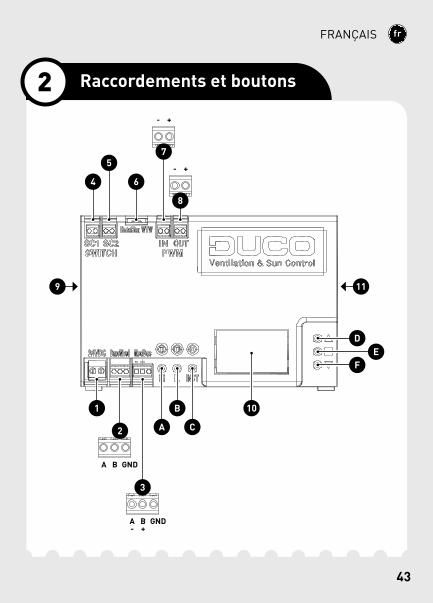
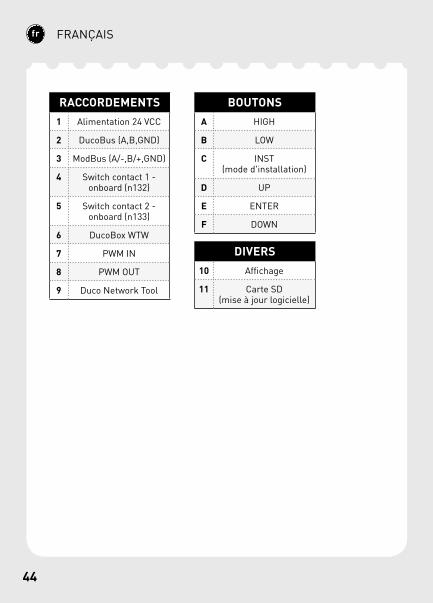
RACCORDEMENTS1 Alimentation 24 VCC
2 DucoBus (A,B,GND)
3 ModBus (A/-,B/+,GND)
4 Switch contact 1 - onboard (n132)
5 Switch contact 2 - onboard (n133)
6 DucoBox WTW
7 PWM IN
8 PWM OUT
9 Duco Network Tool
BOUTONSA HIGH
B LOW
C INST(mode d'installation)
D UP
E ENTER
F DOWN
DIVERS10 Affichage
11 Carte SD (mise à jour logicielle)
45
FRANÇAIS
L'Unité IQ peut communiquer via une connexion sans fil (RF) ou câblée (Wired) avec les composants « esclaves ». Ces deux types de commu-nication peuvent être combinés dans un seul système. Dans les bâti-ments utilitaires et autres projets où de grandes distances ou divers murs et/ou niveaux de construction doivent être franchis, les liaisons câblées (Wired) sont toujours conseillées.
En outre, les raccordements via un Contact de commutation (2 pièces), PWM-IN et PWM-UIT, WTW et ModBus sont possibles.
3 Câblage
46
FRANÇAIS
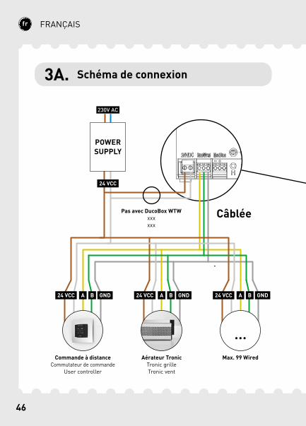
Câblée
24 VCC
24 VCC
A B GND
POWER SUPPLY
Commande à distanceCommutateur de commande
User controller
Aérateur TronicTronic grilleTronic vent
24 VCC A B GND 24 VCC A B GND
Pas avec DucoBox WTWxxxxxx
Max. 99 Wired
3A. Schéma de connexion
47
FRANÇAIS
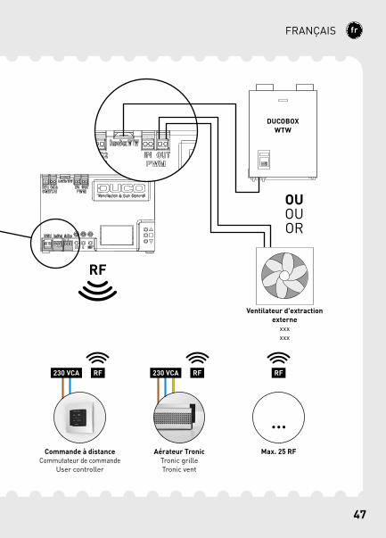
Max. 25 RF
RF230 VCA
Commande à distanceCommutateur de commande
User controller
RF230 VCA
Aérateur TronicTronic grilleTronic vent
DUCOBOX WTW
Ventilateur d'extraction externe
xxxxxx
OUOUOR
RF
RF
48
FRANÇAIS
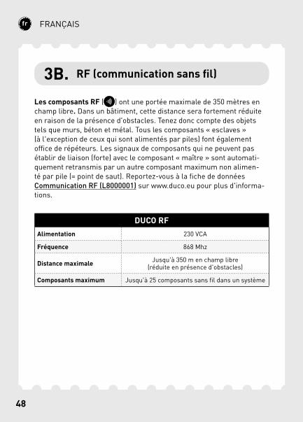
3B. RF (communication sans fil)
Les composants RF ( ) ont une portée maximale de 350 mètres en champ libre. Dans un bâtiment, cette distance sera fortement réduite en raison de la présence d'obstacles. Tenez donc compte des objets tels que murs, béton et métal. Tous les composants « esclaves » (à l'exception de ceux qui sont alimentés par piles) font également office de répéteurs. Les signaux de composants qui ne peuvent pas établir de liaison (forte) avec le composant « maître » sont automati-quement retransmis par un autre composant maximum non alimen-té par pile (= point de saut). Reportez-vous à la fiche de données Communication RF (L8000001) sur www.duco.eu pour plus d'informa-tions.
DUCO RFAlimentation 230 VCA
Fréquence 868 Mhz
Distance maximale Jusqu'à 350 m en champ libre (réduite en présence d'obstacles)
Composants maximum Jusqu'à 25 composants sans fil dans un système
49
FRANÇAIS
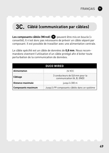
3C. Câblé (communication par câbles)
Les composants câblés (Wired) ( ) peuvent être mis en boucle (= conseillé). Il n'est donc pas nécessaire de prévoir un câble séparé par composant. Il est possible de travailler avec une alimentation centrale.
Le câble spécifié est un câble de données de 0,8 mm. Nous recom-mandons vivement l’utilisation d’un câble protégé afin d’éviter toute perturbation de la communication de données.
DUCO WIREDAlimentation 24 VCC
Câblage 3 conducteurs de 0,8 mm pour la communication (A, B, GND)
Distance maximale jusqu'à 300 m
Composants maximum Jusqu'à 99 composants câblés dans un système
50
FRANÇAIS
3D. Diverses possibilités de câblage
WTWCommunication avec le DucoBox WTW. Dans ce cas, une alimentation 24 VCC séparée pour l'Unité IQ n'est pas nécessaire.
PWM / 0-10VPWM-OUT permet la communication avec un ventilateur ou un action-neur tel qu'un clapet Variable Air Volume (VAV).Le mode de fonctionnement (PWM ou 0-10V) peut être modifié via le menu Affichage du Duco Network Tool. Par défaut, le mode est PWM.PWM-IN permet de commander l'Unité IQ comme un actionneur.
Pour commander plusieurs actionneurs indépendamment l'un de l'autre, il faut une carte d'actionneur par actionneur.
ModBusCommunication avec, par exemple, un système de gestion technique de bâtiment, tant pour la lecture des informations que pour la com-mande du système de ventilation. Reportez-vous à la fiche de données ModBus (L8000008) sur www.duco.eu pour plus d'informations.
51
FRANÇAIS
Contact de commutationLe Contact de commutation peut remplir l'une des fonctions suivantes lors de la fermeture d'un contact hors tension bifilaire (une seule fonc-tion par connexion) : détection de toilettes, couplage avec une pompe à chaleur ou position overrule. Reportez-vous à la fiche de données Menu affichage (L8000014) sur www.duco.eu pour plus d'informations sur son fonctionnement.Pour connecter le composant, le contact doit être fermé une fois.
52
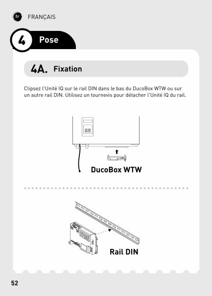
FRANÇAIS
Clipsez l'Unité IQ sur le rail DIN dans le bas du DucoBox WTW ou sur un autre rail DIN. Utilisez un tournevis pour détacher l'Unité IQ du rail.
Rail DIN
DucoBox WTW
4 Pose
4A. Fixation
53
FRANÇAIS
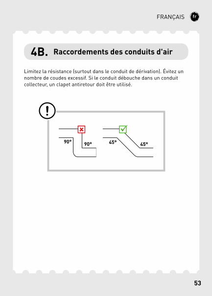
4B. Raccordements des conduits d'air
Limitez la résistance (surtout dans le conduit de dérivation). Évitez un nombre de coudes excessif. Si le conduit débouche dans un conduit collecteur, un clapet antiretour doit être utilisé.
54
FRANÇAIS
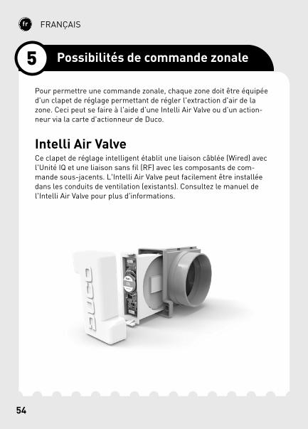
Pour permettre une commande zonale, chaque zone doit être équipée d'un clapet de réglage permettant de régler l'extraction d'air de la zone. Ceci peut se faire à l'aide d'une Intelli Air Valve ou d'un action-neur via la carte d'actionneur de Duco.
Intelli Air ValveCe clapet de réglage intelligent établit une liaison câblée (Wired) avec l'Unité IQ et une liaison sans fil (RF) avec les composants de com-mande sous-jacents. L'Intelli Air Valve peut facilement être installée dans les conduits de ventilation (existants). Consultez le manuel de l'Intelli Air Valve pour plus d'informations.
5 Possibilités de commande zonale
55
FRANÇAIS
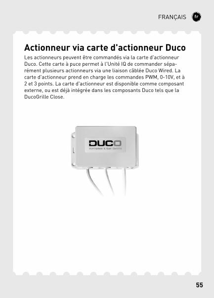
Actionneur via carte d'actionneur DucoLes actionneurs peuvent être commandés via la carte d'actionneur Duco. Cette carte à puce permet à l'Unité IQ de commander sépa-rément plusieurs actionneurs via une liaison câblée Duco Wired. La carte d'actionneur prend en charge les commandes PWM, 0-10V, et à 2 et 3 points. La carte d'actionneur est disponible comme composant externe, ou est déjà intégrée dans les composants Duco tels que la DucoGrille Close.
56
FRANÇAIS
Pour ajouter, supprimer ou remplacer des composants dans le réseau, le système doit se trouver en mode d'installation (Installer mode). La LED de chaque composant indique le mode actif du composant (voir tableau ci-dessous).
Le mode d'installation (Installer mode) peut être activé en appuyant sur le bouton « INST » de l'Unité IQ. Quand la LED se met à clignoter sur l'unité maître, le mode d'installation (Installer mode) est actif. Appuyez de nouveau sur « INST » pour revenir au mode utilisateur (User mode) (LED complètement allumée ou éteinte). Après 15 minutes d'inactivité, le système revient automatiquement au mode Utilisateur (User mode).
6 Installation
6A. Mode d'installation / utilisateur

57
FRANÇAIS
TÉMOIN LED
ROUGE (clignotement lent) Pas en réseau
ROUGE (clignotement rapide) Connexion en cours
VERT (clignotement lent) En réseau
(VERT) (clignotement rapide) En réseau et en attente de composants associés
JAUNE (clignotement lent) Phase de transition (attendre s.v.p.)
JAUNE (allumé) Initialisation
(calibrage du système en cours)
BLANC ou ÉTEINT Normal
58
FRANÇAIS
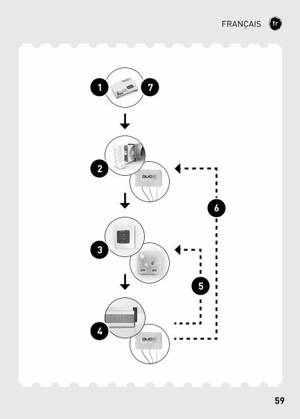
6B. Installation de composants
Suivez les étapes ci-dessous pour connecter des composants à l'Unité IQ.
1 Activez le mode d'installation (Installer mode) en appuyant sur le bouton « INST » de l'Unité IQ. La LED clignotera rapidement en vert.
2 Uniquement pour les systèmes à réglage zonal : Appuyez 1x sur le composant de passage pour connecter ce dernier à l'Unité IQ, de manière que la LED se mette à clignoter en vert. Appuyez une nouvelle fois de manière que la LED se mette à clignoter rapi-dement. Des composants sous-jacents peuvent maintenant être ajoutés dans cette zone.
3 Ajoutez les composants de commande* en appuyant 1x sur le composant à connecter. La LED commencera à clignoter rapide-ment en vert.
4 Ajoutez d'éventuels aérateurs* en appuyant 1x sur le composant à connecter. La LED clignotera lentement en vert.
5 Uniquement pour les systèmes à réglage zonal : Répétez les étapes 3 et 4 jusqu'à ce que tous les autres composants soient connectés dans la zone actuelle. Quittez ensuite la zone actuelle en appuyant une nouvelle fois sur le composant de passage de l'étape 2 . La LED se remet à clignoter lentement en vert.
6 Uniquement pour les systèmes à réglage zonal : Répétez les étapes 2 à 5 pour les zones restantes.
7 Lorsque tous les composants sont connectés, vous pouvez dé-sactiver le mode d'installation (Installer mode) en appuyant sur le bouton « INST » de l'Unité IQ.
Consultez le manuel des composants pour obtenir des informations plus détaillées.
* Attention : seuls des composants RF peuvent être connectés en aval d'une Intelli Air Valve.
59
FRANÇAIS
4
2
3
1 7
5
6
60
FRANÇAIS
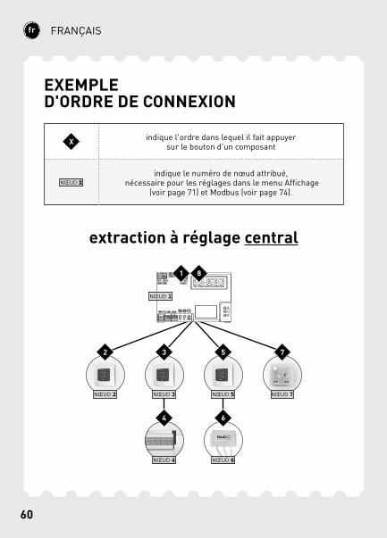
EXEMPLE D'ORDRE DE CONNEXION
extraction à réglage central
NŒUD 2 NŒUD 3 NŒUD 5 NŒUD 7
NŒUD 4 NŒUD 6
NŒUD 1
1
2 3
4
5
6
7
8
X indique l'ordre dans lequel il fait appuyer sur le bouton d'un composant
NŒUD Xindique le numéro de nœud attribué,
nécessaire pour les réglages dans le menu Affichage (voir page 71) et Modbus (voir page 74).

61
FRANÇAIS
extraction à réglage zonal
NŒUD 1
NŒUD 2 NŒUD 6 NŒUD 8 NŒUD 9
NŒUD 3 NŒUD 7
NŒUD 4 NŒUD 5
NŒUD 10 NŒUD 11
1
92
10
311
4
12
5
13
6
147
15
8
16
17
18
62
FRANÇAIS
6C. Autres actions
Activez le mode d'installation (Installer mode) pour supprimer ou remplacer un composant. Il est possible que cela puisse se faire via le composant lui-même ; consultez pour ce faire le manuel du composant en question.
Éliminer un composantAppuyez 1 x longuement sur un bouton du composant afin de le sup-primer du réseau.
Remplacer un composantAppuyez 2 x brièvement sur le bouton du composant à supprimer. Appuyez ensuite 1x brièvement sur le bouton du nouveau composant. Celui-ci reprendra tous les réglages/couplages du réseau.
ConseilsPour supprimer tous les composants du réseau (par exemple en cas de problèmes), il est possible d'appuyer longuement sur « INST » en mode d'installation (Installer mode) jusqu'à ce que la LED rouge se mette à clignoter. L'Unité IQ redémarrera (environ 15 secondes) et la LED cessera de clignoter.
Utilisez le Duco Network Tool pour lire les informations des compo-sants.
Ne connectez jamais plus d'un système avec des composants RF simultanément.
63
FRANÇAIS
Pour que le système fonctionne correctement, il doit être calibré. Cela garantit un fonctionnement aussi silencieux que possible et efficace au niveau énergétique.
Pour plus d'informations sur la détermination des débits de ventilation, consultez la section Tools sur www.duco.eu.
Le calibrage se fait en deux phases : réglage des bouches d'extraction et calibrage effectif.
Les bouches d'extraction seront placées dans un canal d'évacuation pour aspirer l'air humide ou vicié. Pour un calibrage correct, les bouches doivent être réglées en fonction de la méthode d'extraction.Extraction centrale : réglez les bouches de manière qu'elles corres-pondent au débit souhaité conformément au tableau suivant.Extraction zonale : réglez les bouches selon les méthodes suivantes, en fonction de la situation par zone.
Si vous utilisez des bouches DucoVent Design, laissez toujours l'an-neau extérieur en place pour assurer le fonctionnement acoustique.
7 Calibrage
7A. Réglage des bouches d'extraction
64
FRANÇAIS
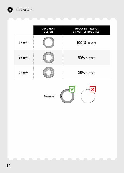
DUCOVENT DESIGN
DUCOVENT BASICET AUTRES BOUCHES
75 m3/h 100 % ouvert
50 m3/h 50% ouvert
25 m3/h 25% ouvert
Mousse
65
FRANÇAIS
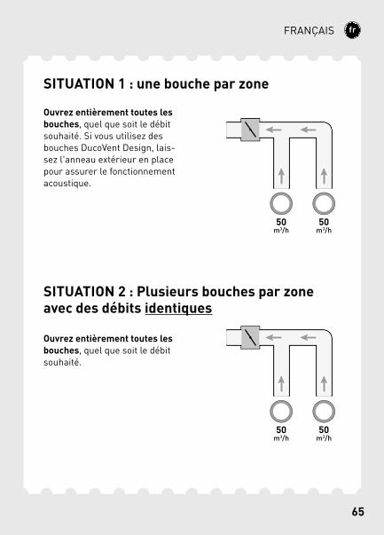
SITUATION 1 : une bouche par zone
Ouvrez entièrement toutes les bouches, quel que soit le débit souhaité. Si vous utilisez des bouches DucoVent Design, lais-sez l'anneau extérieur en place pour assurer le fonctionnement acoustique.
SITUATION 2 : Plusieurs bouches par zone avec des débits identiques
Ouvrez entièrement toutes les bouches, quel que soit le débit souhaité.
66
FRANÇAIS
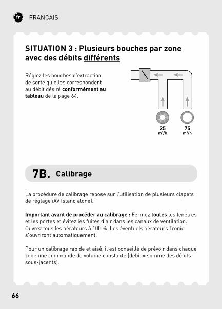
SITUATION 3 : Plusieurs bouches par zone avec des débits différents
Réglez les bouches d'extraction de sorte qu'elles correspondent au débit désiré conformément au tableau de la page 64.
7B. Calibrage
La procédure de calibrage repose sur l'utilisation de plusieurs clapets de réglage iAV (stand alone).
Important avant de procéder au calibrage : Fermez toutes les fenêtres et les portes et évitez les fuites d'air dans les canaux de ventilation. Ouvrez tous les aérateurs à 100 %. Les éventuels aérateurs Tronic s'ouvriront automatiquement.
Pour un calibrage rapide et aisé, il est conseillé de prévoir dans chaque zone une commande de volume constante (débit = somme des débits sous-jacents).
67
FRANÇAIS
PWM
2
3
4
49
5a5b
6
7
8b8b
1
75 m³/h50 m³/h25 m³/h
75 m³/h50 m³/h25 m³/h
150 m³/h
150 m³/h
Zone 2
Zone 1
Commande de volume constante
68
FRANÇAIS
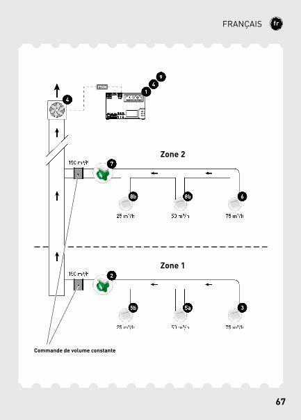
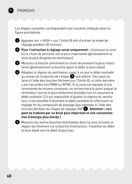
Les étapes suivantes correspondent aux numéros indiqués dans la figure précédente.
1 Appuyez sur « HIGH » sur l'Unité IQ afin d'activer le mode de réglage pendant 30 minutes.
2 Pour l'extraction à réglage zonal uniquement : choisissez la zone où la chute de pression est la plus importante (généralement la zone la plus éloignée du ventilateur).
3 Mesurez la bouche présentant la chute de pression la plus impor-tante (généralement la bouche ayant le débit le plus élevé).
4 Adaptez le régime du ventilateur jusqu'à ce que le débit souhaité au niveau de la bouche de l'étape 3 soit atteint. Ceci peut se faire à l'aide des touches fléchées sur l'Unité IQ, si cette dernière y est raccordée (via PWM ou WTW). Si la zone est équipée d'une commande de volume constante, on recherchera le point auquel le ventilateur tourne le plus lentement possible tout en assurant le débit souhaité. S'il est impossible d'ajuster le régime du ventila-teur, il est possible d'atteindre le débit souhaité en effectuant un réglage fin du composant de passage (par exemple à l'aide des touches fléchées du Clapet de réglage iAV) 2 . Attention : ceci peut se traduire par un bruit plus important et une consomma-tion d'énergie plus élevée !
5 Mesurez les autres bouches éventuelles dans la zone actuelle et réglez-les finement via la bouche d'extraction. Travaillez du débit le plus élevé vers le débit le plus bas.
69
FRANÇAIS
Passez aux zones suivantes. Répétez pour ce faire les étapes suivantes et procédez en direction du ventilateur.
6 Choisissez la bouche dont le débit est le plus élevé.7 Adaptez le débit de la bouche de l'étape 6 en effectuant un
réglage fin du composant de passage (par exemple à l'aide des touches fléchées du Clapet de réglage iAV).
8 Mesurez les autres bouches éventuelles dans la zone actuelle et réglez-les finement via la bouche d'extraction. Travaillez du débit le plus élevé vers le débit le plus bas.
9 Quittez le mode de réglage en appuyant sur le bouton « HIGH » d'un Clapet de réglage iAV ou de l'Unité IQ.
70
FRANÇAIS
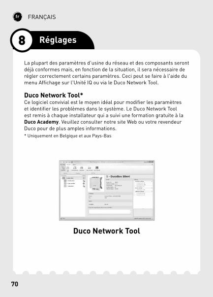
La plupart des paramètres d'usine du réseau et des composants seront déjà conformes mais, en fonction de la situation, il sera nécessaire de régler correctement certains paramètres. Ceci peut se faire à l'aide du menu Affichage sur l'Unité IQ ou via le Duco Network Tool.
Duco Network Tool*Ce logiciel convivial est le moyen idéal pour modifier les paramètres et identifier les problèmes dans le système. Le Duco Network Tool est remis à chaque installateur qui a suivi une formation gratuite à la Duco Academy. Veuillez consulter notre site Web ou votre revendeur Duco pour de plus amples informations.* Uniquement en Belgique et aux Pays-Bas
Duco Network Tool
8 Réglages
71
FRANÇAIS
DISPLAYMENU
Display menuL'utilisation du menu se fait à l'aide des touches fléchées ( , ) et de la touche enter ( ). Pour faire défiler le menu, utilisez les touches fléchées. Pour revenir au menu supérieur, appuyez sur « >BACK » à la fin de chaque menu. Appuyez brièvement sur les touches fléchées simultanément pour revenir au menu principal.Après 2 minutes d'inactivité, le display sera automatiquement désacti-vé. Appuyez sur un bouton ( , ou ) pour réactiver l'affichage.
Reportez-vous à la fiche de données Menu affichage (L8000014) sur www.duco.eu pour un aperçu complet du Display menu.
72
FRANÇAIS
8A. Réglage de l'heure
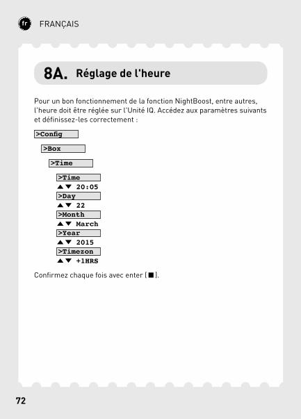
Pour un bon fonctionnement de la fonction NightBoost, entre autres, l'heure doit être réglée sur l'Unité IQ. Accédez aux paramètres suivants et définissez-les correctement :
>Config
>Box
>Time
>Time 20:05 >Day 22 >Month March >Year 2015 >Timezon +1HRS
Confirmez chaque fois avec enter ( ).
73
FRANÇAIS
8B. NightBoost
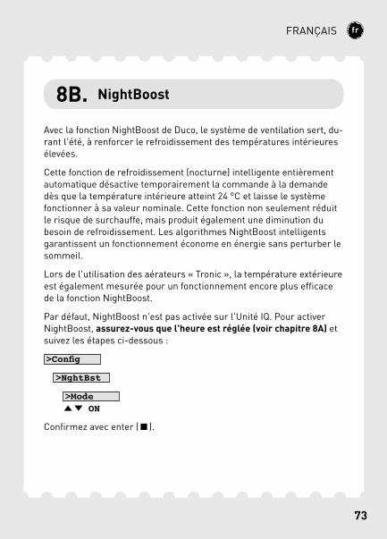
Avec la fonction NightBoost de Duco, le système de ventilation sert, du-rant l'été, à renforcer le refroidissement des températures intérieures élevées.
Cette fonction de refroidissement (nocturne) intelligente entièrement automatique désactive temporairement la commande à la demande dès que la température intérieure atteint 24 °C et laisse le système fonctionner à sa valeur nominale. Cette fonction non seulement réduit le risque de surchauffe, mais produit également une diminution du besoin de refroidissement. Les algorithmes NightBoost intelligents garantissent un fonctionnement économe en énergie sans perturber le sommeil.
Lors de l'utilisation des aérateurs « Tronic », la température extérieure est également mesurée pour un fonctionnement encore plus efficace de la fonction NightBoost.
Par défaut, NightBoost n'est pas activée sur l'Unité IQ. Pour activer NightBoost, assurez-vous que l'heure est réglée (voir chapitre 8A) et suivez les étapes ci-dessous :
>Config
>NghtBst
>Mode ON
Confirmez avec enter ( ).
74
FRANÇAIS
8C. ModBus
Via une connexion ModBus, il est possible de lire et de modifier les paramètres du système de ventilation à partir d'un équipement couplé (par exemple : un système de gestion technique de bâtiment). Repor-tez-vous à la fiche de données ModBus (L8000008) sur www.duco.eu pour des informations détaillées sur ModBus.
75
ENGLISH
English
Table of contents1 Application ...................................................................................................................................................76
Centrally controlled exhaust ..............................................................................................77
Zonally controlled exhaust....................................................................................................78
2 Connectors and buttons ................................................................................................................79
3 Cabling .............................................................................................................................................................81
Cabling diagram ..............................................................................................................................82
RF (wireless communication) ............................................................................................84
Wired (cabled communication).........................................................................................85
Various cabling options ............................................................................................................86
4 Installation ..................................................................................................................................................88
Mounting .................................................................................................................................................88
Air duct connections ...................................................................................................................89
5 Zonal control options .......................................................................................................................90
6 Installation ..................................................................................................................................................92
Installer / User mode .................................................................................................................92
Installing components...............................................................................................................94
Other operations .............................................................................................................................98
7 Configuration ............................................................................................................................................99
Setting exhaust vents .................................................................................................................99
Configuration ...................................................................................................................................102
8 Settings ....................................................................................................................................................... 106
Setting the time .............................................................................................................................108
NightBoost..........................................................................................................................................109
ModBus ..................................................................................................................................................110
76
ENGLISH
The IQ-unit operates as a ‘master’ or brain within Duco's De-mand-Controlled Natural Ventilation Systems.It receives and interprets signals from the ‘slave’ components (meas-urements from a sensor or manual input), based on which it controls the ventilation system and any external unit. The IQ-unit thus ensures that stale air, with excessive CO2 or moisture content, is exhausted.
The IQ-unit boasts smart functions such as NightBoost and ventilative cooling, and can also be connected to a building management system via ModBus.
The IQ-unit can be used in different situations and can perform dif-ferent functions depending on requirements and the type of central extract unit:
DucoBox WTWThe IQ-unit controls the DucoBox WTW via the WTW connection.
Pressure-controlled fanWith this the IQ-unit is not connected to the central extract unit. In this case, the IQ-unit is only required to utilise functions such as ModBus, NightBoost and ventilative cooling.
Non-pressure-controlled fanThe IQ-unit controls the fan via a PWM connection.
With the IQ-unit, both centrally and zonally controlled exhaust is available.
1 Application
77
ENGLISH
*PWM
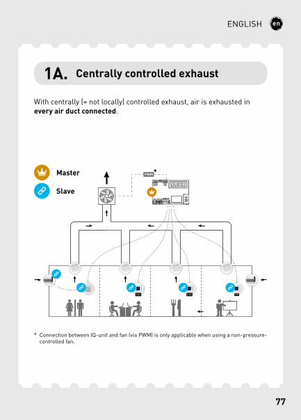
With centrally (= not locally) controlled exhaust, air is exhausted in every air duct connected.
1A. Centrally controlled exhaust
Master
Slave
* Connection between IQ-unit and fan (via PWM) is only applicable when using a non-pressure-controlled fan.
78
ENGLISH
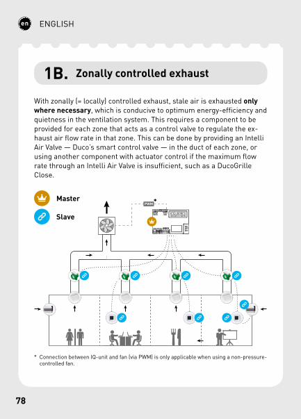
1B. Zonally controlled exhaust
With zonally (= locally) controlled exhaust, stale air is exhausted only where necessary, which is conducive to optimum energy-efficiency and quietness in the ventilation system. This requires a component to be provided for each zone that acts as a control valve to regulate the ex-haust air flow rate in that zone. This can be done by providing an Intelli Air Valve — Duco’s smart control valve — in the duct of each zone, or using another component with actuator control if the maximum flow rate through an Intelli Air Valve is insufficient, such as a DucoGrille Close.
PWM*Master
Slave
* Connection between IQ-unit and fan (via PWM) is only applicable when using a non-pressure-controlled fan.
79
ENGLISH
4
1
5
2
6
3
10
7
A
8
B
C
FE
D
119
A
A
B
B
GND
GND
- +
- +
- +
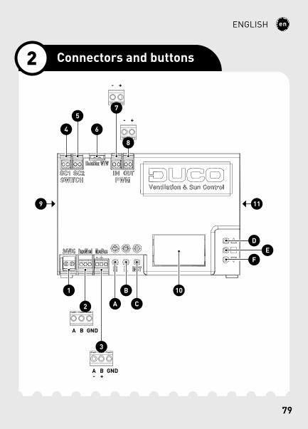
2 Connectors and buttons
80
ENGLISH
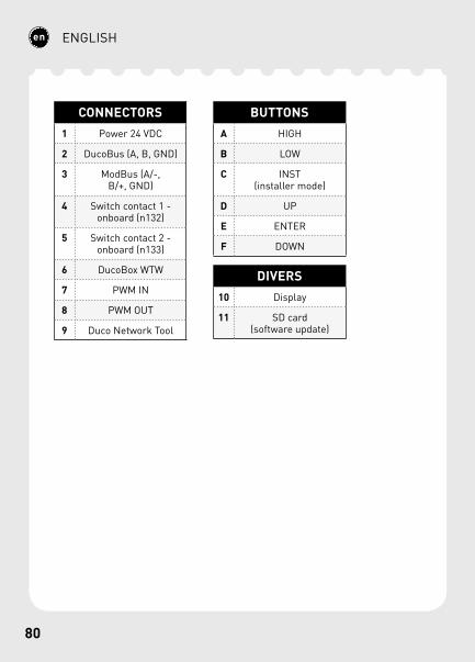
CONNECTORS1 Power 24 VDC
2 DucoBus (A, B, GND)
3 ModBus (A/-, B/+, GND)
4 Switch contact 1 - onboard (n132)
5 Switch contact 2 - onboard (n133)
6 DucoBox WTW
7 PWM IN
8 PWM OUT
9 Duco Network Tool
BUTTONSA HIGH
B LOW
C INST(installer mode)
D UP
E ENTER
F DOWN
DIVERS10 Display
11 SD card (software update)
81
ENGLISH
The IQ-unit is able to communicate with slave components via a wire-less (RF) or wired link. Both types of communication can be combined in one system. Wired connections are to be recommended in all cases of non-residential and other projects where large distances or various walls and/or building levels need to be spanned.
In addition, connections can also be made via a Switch Sensor (quantity of 2), PWM-IN and PWM-OUT, WTW and ModBus.
3 Cabling
82
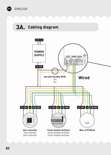
ENGLISH
Wired
24 VDC
24 VDC
A B GND
POWER SUPPLY
User controllerUser controller
User controller
Tronic window ventilatorTronic window ventilatorTronic window ventilator
24 VDC A B GND 24 VDC A B GND
Not with DucoBox WTWxxxxxx
Max. of 99 Wired
3A. Cabling diagram
83
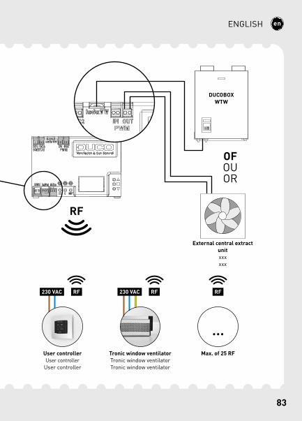
ENGLISH
Max. of 25 RF
RF230 VAC
User controllerUser controller
User controller
RF230 VAC
Tronic window ventilatorTronic window ventilatorTronic window ventilator
DUCOBOX WTW
External central extract unitxxxxxx
OFOUOR
RF
RF
84
ENGLISH
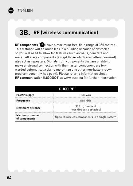
3B. RF (wireless communication)
RF components ( ) have a maximum free-field range of 350 metres. This distance will be much less in a building because of obstacles so you will need to allow for features such as walls, concrete and metal. All slave components (except those which are battery powered) also act as repeaters. Signals from components that are unable to make a (strong) connection with the master component are for-warded automatically via no more than one other non-battery-pow-ered component (= hop point). Please refer to information sheet RF communication (L8000001) at www.duco.eu for further information.
DUCO RFPower supply 230 VAC
Frequency 868 MHz
Maximum distance 350 m, free field (less through obstacles)
Maximum number of components Up to 25 wireless components in a single system
85
ENGLISH
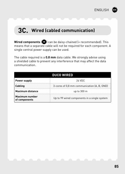
3C. Wired (cabled communication)
Wired components ( ) can be daisy-chained (= recommended). This means that a separate cable will not be required for each component. A single central power supply can be used.
The cable required is a 0.8 mm data cable. We strongly advise using a shielded cable to prevent any interference that may affect the data communication.
DUCO WIREDPower supply 24 VDC
Cabling 3-cores of 0,8 mm communication (A, B, GND)
Maximum distance up to 300 m
Maximum number of components Up to 99 wired components in a single system
86
ENGLISH
3D. Various cabling options
WTWCommunication with the DucoBox WTW. In this case a separate 24 VDC is not required for the IQ-unit.
PWM / 0-10 VPWM-OUT enables communication with a central extract unit or an actuator such as a Variable Air Volume (VAV) valve.Its operating mode (PWM or 0-10 V) can be changed using the display menu or the Duco Network Tool. It is set to PWM as standard.PWM-IN enables the IQ-unit to be controlled like an actuator.
An Actuatorprint is required for each actuator to control multiple actu-ators independently of one another.
ModBusCommunications with building management systems for instance, for reading out information as well as controlling the ventilation system. Please refer to information sheet ModBus (L8000009) at www.duco.eu for more information.
87
ENGLISH
Switch SensorThe Switch Sensor can perform one of the following functions when closing one contact in a two-pole zero voltage contact (only one func-tion per connection): toilet detection, link to heat pump or overrule setting. Please refer to information sheet Display menu (L8000015) at www.duco.eu for more information about its operation.The contact needs to be closed once in order to pair the component.
88
ENGLISH
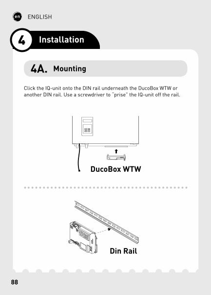
Click the IQ-unit onto the DIN rail underneath the DucoBox WTW or another DIN rail. Use a screwdriver to “prise” the IQ-unit off the rail.
Din Rail
DucoBox WTW
4 Installation
4A. Mounting
89
ENGLISH
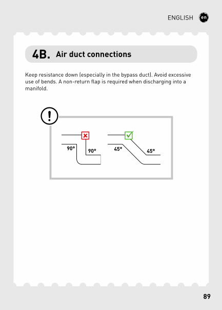
4B. Air duct connections
Keep resistance down (especially in the bypass duct). Avoid excessive use of bends. A non-return flap is required when discharging into a manifold.
90
ENGLISH
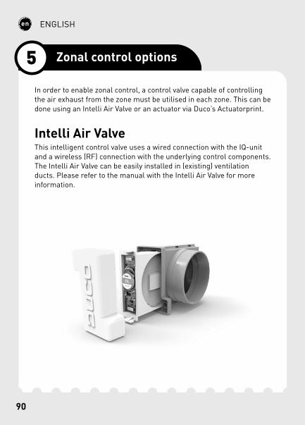
In order to enable zonal control, a control valve capable of controlling the air exhaust from the zone must be utilised in each zone. This can be done using an Intelli Air Valve or an actuator via Duco’s Actuatorprint.
Intelli Air ValveThis intelligent control valve uses a wired connection with the IQ-unit and a wireless (RF) connection with the underlying control components. The Intelli Air Valve can be easily installed in (existing) ventilation ducts. Please refer to the manual with the Intelli Air Valve for more information.
5 Zonal control options
91
ENGLISH
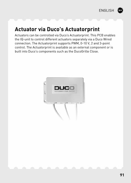
Actuator via Duco's ActuatorprintActuators can be controlled via Duco’s Actuatorprint. This PCB enables the IQ-unit to control different actuators separately via a Duco Wired connection. The Actuatorprint supports PWM, 0-10 V, 2 and 3-point control. The Actuatorprint is available as an external component or is built into Duco's components such as the DucoGrille Close.
92
ENGLISH
To add, remove or replace components in the network, the system must be set to ‘Installer mode’. The LED on each component indicates the active mode of the component (see table below).
‘Installer mode’ can be activated by pressing the IQ-unit ‘INST’ button. Once the LED on the master unit starts flashing, it means that ‘Installer mode’ is active. Press ‘INST’ again to return to ‘User mode’ (LED fully on or off). The system reverts automatically to ‘User mode’ after 15 minutes of inactivity.
6 Installation
6A. Installer / User mode
93
ENGLISH
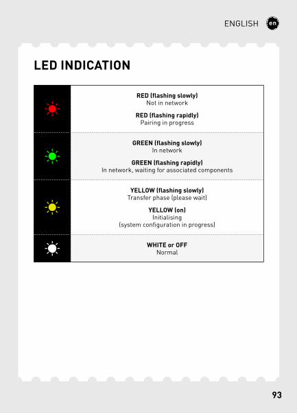
LED INDICATION
RED (flashing slowly) Not in network
RED (flashing rapidly) Pairing in progress
GREEN (flashing slowly) In network
GREEN (flashing rapidly) In network, waiting for associated components
YELLOW (flashing slowly) Transfer phase (please wait)
YELLOW (on) Initialising
(system configuration in progress)
WHITE or OFF Normal
94
ENGLISH
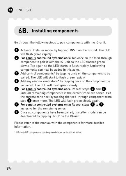
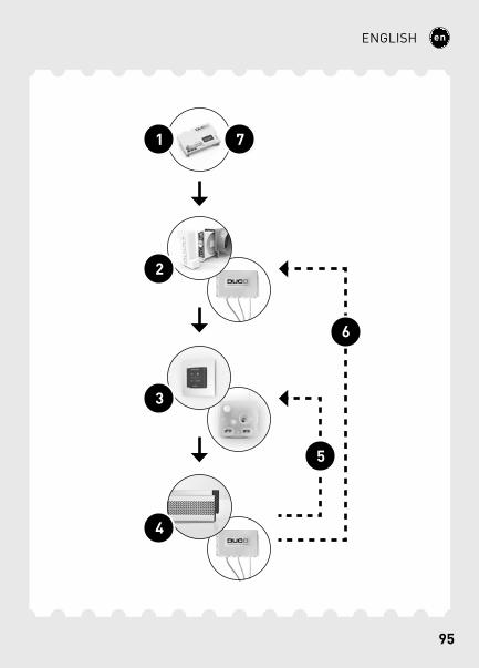
6B. Installing components
Go through the following steps to pair components with the IQ-unit.
1 Activate ‘Installer mode’ by tapping ‘INST’ on the IQ-unit. The LED will flash green rapidly.
2 For zonally controlled systems only: Tap once on the feed-through component to pair it with the IQ-unit so the LED flashes green slowly. Tap again so the LED starts to flash rapidly. Underlying components can now be added in this zone.
3 Add control components* by tapping once on the component to be paired. The LED will start to flash green rapidly.
4 Add any window ventilators* by tapping once on the component to be paired. The LED will flash green slowly.
5 For zonally controlled systems only: Repeat steps 3 and 4 until all remaining components in the current zone are paired. Exit the current zone next by tapping the feed-through component from step 2 once more. The LED will flash green slowly again.
6 For zonally controlled systems only: Repeat steps 2 to 5 inclusive for the remaining zones.
7 Once all components have been paired, ‘Installer mode’ can be deactivated by tapping ‘INST’ on the IQ-unit.
Please refer to the manual with the components for more detailed information.
* NB: only RF components can be paired under an Intelli Air Valve.
95
ENGLISH
4
2
3
1 7
5
6
96
ENGLISH
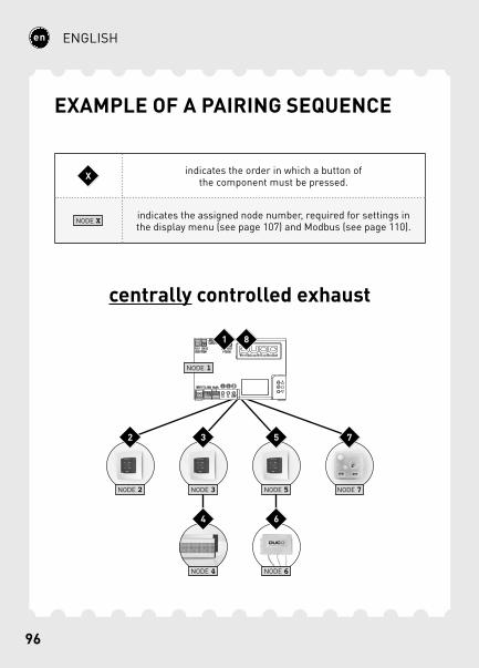
EXAMPLE OF A PAIRING SEQUENCE
centrally controlled exhaust
NODE 2 NODE 3 NODE 5 NODE 7
NODE 4 NODE 6
NODE 1
1
2 3
4
5
6
7
8
X indicates the order in which a button of the component must be pressed.
NODE X indicates the assigned node number, required for settings in the display menu (see page 107) and Modbus (see page 110).

97
ENGLISH
zonally controlled exhaust
NODE 1
NODE 2 NODE 6 NODE 8 NODE 9
NODE 3 NODE 7
NODE 4 NODE 5
NODE 10 NODE 11
1
92
10
311
4
12
5
13
6
147
15
8
16
17
18
98
ENGLISH
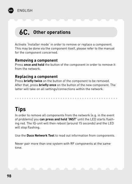
6C. Other operations
Activate ‘Installer mode’ in order to remove or replace a component. This may be done via the component itself, please refer to the manual for the component concerned.
Removing a componentPress once and hold the button of the component in order to remove it from the network.
Replacing a componentPress briefly twice on the button of the component to be removed. After that, press briefly once on the button of the new component. The latter will take on all settings/connections within the network.
TipsIn order to remove all components from the network (e.g. in the event of problems) you can press and hold ‘INST’ until the LED starts flash-ing red. The IQ-unit will then reboot (around 15 seconds) and the LED will stop flashing.
Use the Duco Network Tool to read out information from components.
Never pair more than one system with RF components at the same time.
99
ENGLISH
The system needs to be configured for it to work correctly. This will ensure its operation is as quiet and as energy-efficient as possible.
See under the Tools heading at www.duco.eu for info about determining ventilation flow rates.
Configuration takes place in two stages: setting exhaust vents and actual configuration.
The exhaust vents are installed in an exhaust duct for humid/stale air extraction. For correct configuration, the vents must be set depending on the exhaust method:Central exhaust: set the vents to match the desired flow rate in accord-ance with the following table.Zonal exhaust: set the vents in accordance with the methods that follow, depending on the situation in each zone.
When using DucoVent Design, exhaust vents always leave the outer ring in place for acoustic effect.
7 Configuration
7A. Setting exhaust vents
100
ENGLISH
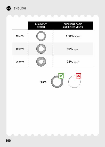
DUCOVENT DESIGN
DUCOVENT BASICAND OTHER VENTS
75 m3/h 100% open
50 m3/h 50% open
25 m3/h 25% open
Foam
101
ENGLISH
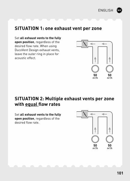
SITUATION 1: one exhaust vent per zone
Set all exhaust vents to the fully open position, regardless of the desired flow rate. When using DucoVent Design exhaust vents, leave the outer ring in place for acoustic effect.
SITUATION 2: Multiple exhaust vents per zone with equal flow rates
Set all exhaust vents to the fully open position, regardless of the desired flow rate.
102
ENGLISH
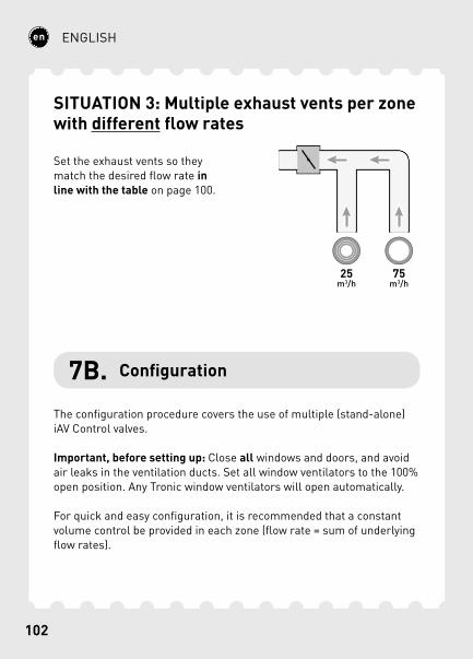
SITUATION 3: Multiple exhaust vents per zone with different flow rates
Set the exhaust vents so they match the desired flow rate in line with the table on page 100.
7B. Configuration
The configuration procedure covers the use of multiple (stand-alone) iAV Control valves.
Important, before setting up: Close all windows and doors, and avoid air leaks in the ventilation ducts. Set all window ventilators to the 100% open position. Any Tronic window ventilators will open automatically.
For quick and easy configuration, it is recommended that a constant volume control be provided in each zone (flow rate = sum of underlying flow rates).
103
ENGLISH
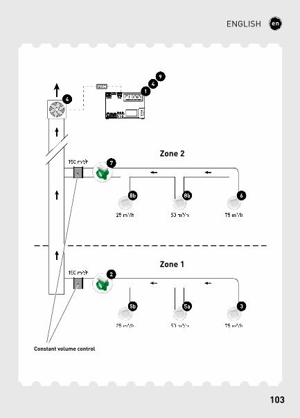
PWM
2
3
4
49
5a5b
6
7
8b8b
1
75 m³/h50 m³/h25 m³/h
75 m³/h50 m³/h25 m³/h
150 m³/h
150 m³/h
Zone 2
Zone 1
Constant volume control
104
ENGLISH
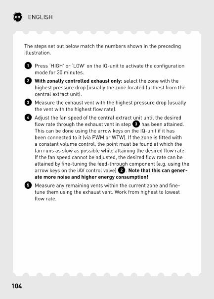
The steps set out below match the numbers shown in the preceding illustration.
1 Press ‘HIGH’ or ‘LOW’ on the IQ-unit to activate the configuration mode for 30 minutes.
2 With zonally controlled exhaust only: select the zone with the highest pressure drop (usually the zone located furthest from the central extract unit).
3 Measure the exhaust vent with the highest pressure drop (usually the vent with the highest flow rate).
4 Adjust the fan speed of the central extract unit until the desired flow rate through the exhaust vent in step 3 has been attained. This can be done using the arrow keys on the IQ-unit if it has been connected to it (via PWM or WTW). If the zone is fitted with a constant volume control, the point must be found at which the fan runs as slow as possible while attaining the desired flow rate. If the fan speed cannot be adjusted, the desired flow rate can be attained by fine-tuning the feed-through component (e.g. using the arrow keys on the iAV control valve) 2 . Note that this can gener-ate more noise and higher energy consumption!
5 Measure any remaining vents within the current zone and fine-tune them using the exhaust vent. Work from highest to lowest flow rate.
105
ENGLISH
Now complete the remaining zones. To do this, repeat the following steps, working towards the central extract unit.
6 Select the exhaust vent with the highest flow rate.7 Adjust the flow rate through the exhaust vent in step 6 by
fine-tuning the feed-through component (e.g. using the arrow keys on the iAV control valve).
8 Measure any remaining vents within the current zone and fine-tune them using the exhaust vent. Work from highest to lowest flow rate.
9 Exit configuration mode by pressing ‘HIGH’ on the iAV Control valve or on the IQ-unit.
106
ENGLISH
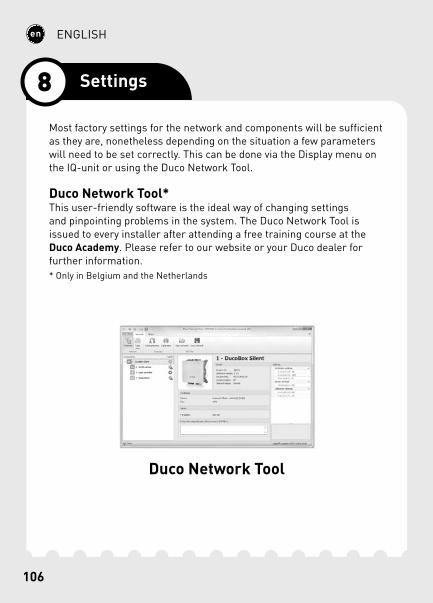
Most factory settings for the network and components will be sufficient as they are, nonetheless depending on the situation a few parameters will need to be set correctly. This can be done via the Display menu on the IQ-unit or using the Duco Network Tool.
Duco Network Tool*This user-friendly software is the ideal way of changing settings and pinpointing problems in the system. The Duco Network Tool is issued to every installer after attending a free training course at the Duco Academy. Please refer to our website or your Duco dealer for further information.* Only in Belgium and the Netherlands
Duco Network Tool
8 Settings
107
ENGLISH
DISPLAYMENU
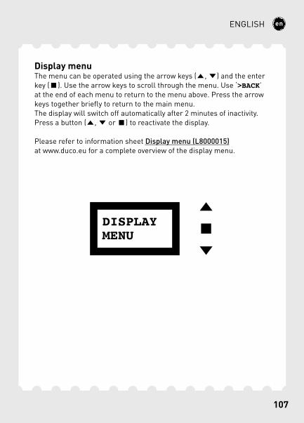
Display menuThe menu can be operated using the arrow keys ( , ) and the enter key ( ). Use the arrow keys to scroll through the menu. Use ‘>BACK’ at the end of each menu to return to the menu above. Press the arrow keys together briefly to return to the main menu.The display will switch off automatically after 2 minutes of inactivity. Press a button ( , or ) to reactivate the display.
Please refer to information sheet Display menu (L8000015) at www.duco.eu for a complete overview of the display menu.
108
ENGLISH
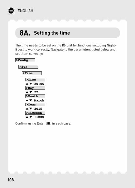
8A. Setting the time
The time needs to be set on the IQ-unit for functions including Night-Boost to work correctly. Navigate to the parameters listed below and set them correctly:
>Config
>Box
>Time
>Time 20:05 >Day 22 >Month March >Year 2015 >Timezon +1HRS
Confirm using Enter ( ) in each case.
109
ENGLISH
8B. NightBoost
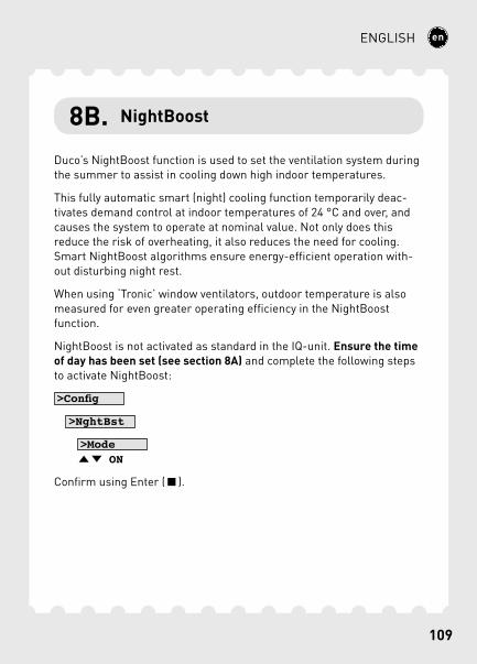
Duco’s NightBoost function is used to set the ventilation system during the summer to assist in cooling down high indoor temperatures.
This fully automatic smart (night) cooling function temporarily deac-tivates demand control at indoor temperatures of 24 °C and over, and causes the system to operate at nominal value. Not only does this reduce the risk of overheating, it also reduces the need for cooling. Smart NightBoost algorithms ensure energy-efficient operation with-out disturbing night rest.
When using ‘Tronic’ window ventilators, outdoor temperature is also measured for even greater operating efficiency in the NightBoost function.
NightBoost is not activated as standard in the IQ-unit. Ensure the time of day has been set (see section 8A) and complete the following steps to activate NightBoost:
>Config
>NghtBst
>Mode ON
Confirm using Enter ( ).

110
ENGLISH
8C. ModBus
A ModBus link can be used to read out and alter ventilation system parameters from connected equipment (e.g. a building management system). Please refer to information sheet ModBus (L8000009) at www.duco.eu for comprehensive information about ModBus.

111
Geïnstalleerd door:Installé par:Installed by: