Hoofdstuk 6 – Ondiepe geothermie – BEO en verticale ...
32
Background document – Hoofdstuk 6 1 Hoofdstuk 6 – Ondiepe geothermie – BEO en verticale bodemwisselaars 6.1. Principe Verticale bodemwarmtewisselaars zijn gesloten systemen met buizen (PE-leidingen) die verticaal tot een diepte van 100 meter of meer in de grond aangebracht worden. Door de buizen stroomt een vloeistof die opgewarmd of afgekoeld wordt door contact met de bodem. In vergelijking met horizontale systemen hebben verticale warmtewisselaars een beter rendement, en kunnen ze worden toegepast als er niet genoeg horizontale oppervlakte beschikbaar is. De kost van de verticale systemen is echter hoger dan die van horizontale warmtewisselaars. Afhankelijk van het type grond, de beschikbare ruimte, en de warmte/koude behoefte, zal een enkel boorgat 1kW of meer (20 tot 50 W/m) kunnen opleveren (IGHSPA, 2009). 6.1.1. Benodigde informatie Volgens ISSO-publicatie 81 (2007), is de benodigde informatie voor een project met verticale warmtewisselaars als volgt: 1) Welke functie(s) dient het comfortsysteem te vervullen verwarmen; verwarmen en koelen (actief of passief); warmtapwater bereiding. 2) Globale informatie bodemgesteldheid Aanwezigheid leidingen en kabels in de bodem; Grondwaterstroming: Grondwatersnelheid < 5 m per jaar: de invloed ervan kan worden verwaarloosd; Grondwatersnelheid 5 m per jaar: - geen regeneratie: positief effect op de prestatie van het bodemsysteem; - 0 tot 50 % regeneratie Iicht positief tot neutraal effect; - 50 tot 100 % regeneratie; er moet gebruik worden gemaakt van een bodem simulatiepakket, dat rekening houdt met grondwaterstroming. Grondwatergebruik (waterwingebieden) Aanwezigheid van energieopslag (aquifer) in de beoogde bodemlaag Aangrenzende bodemwarmtesystemen (grootte warmte-/koudevraag) Bodem opbouw Welke inbrengtechnieken zijn toepasbaar op de gewenste locatie. Bouwkundige aspecten: muur/vloerdoorvoeringen. When determining if a vertically-bored GHEX is a suitable choice for a given installation, key questions to answer before the design process can begin are (IGHSPA 2009): - Are vertical GHEX installations allowed in the given area? - Do ground conditions exist that will prevent the installation of a vertical GHEX such as caves, voids, sinkhole potential, or any other known natural impediments? - Is a vertically-bored installation the most cost effective option as compared to other usable closed loop alternatives? - After considering code setback requirements and easements, does enough green space exist for the installation? If not, is the additional space under existing or planned driveways, sidewalks, etc., enough to accommodate installation space requirements?
Transcript of Hoofdstuk 6 – Ondiepe geothermie – BEO en verticale ...
Background document – Hoofdstuk 6
1
Hoofdstuk 6 – Ondiepe geothermie – BEO en verticale bodemwisselaars
6.1. Principe
Verticale bodemwarmtewisselaars zijn gesloten systemen met buizen (PE-leidingen) die verticaal tot een diepte van 100 meter of meer in de grond aangebracht worden. Door de buizen stroomt een vloeistof die opgewarmd of afgekoeld wordt door contact met de bodem.
In vergelijking met horizontale systemen hebben verticale warmtewisselaars een beter rendement, en kunnen ze worden toegepast als er niet genoeg horizontale oppervlakte beschikbaar is. De kost van de verticale systemen is echter hoger dan die van horizontale warmtewisselaars. Afhankelijk van het type grond, de beschikbare ruimte, en de warmte/koude behoefte, zal een enkel boorgat 1kW of meer (20 tot 50 W/m) kunnen opleveren (IGHSPA, 2009).
6.1.1. Benodigde informatie
Volgens ISSO-publicatie 81 (2007), is de benodigde informatie voor een project met verticale warmtewisselaars als volgt:
1) Welke functie(s) dient het comfortsysteem te vervullen
verwarmen;
verwarmen en koelen (actief of passief);
warmtapwater bereiding.
2) Globale informatie bodemgesteldheid
Aanwezigheid leidingen en kabels in de bodem;
Grondwaterstroming:
Grondwatersnelheid < 5 m per jaar: de invloed ervan kan worden verwaarloosd;
Grondwatersnelheid 5 m per jaar: - geen regeneratie: positief effect op de prestatie van het bodemsysteem; - 0 tot 50 % regeneratie Iicht positief tot neutraal effect; - 50 tot 100 % regeneratie; er moet gebruik worden gemaakt van een bodem simulatiepakket,
dat rekening houdt met grondwaterstroming.
Grondwatergebruik (waterwingebieden)
Aanwezigheid van energieopslag (aquifer) in de beoogde bodemlaag
Aangrenzende bodemwarmtesystemen (grootte warmte-/koudevraag)
Bodem opbouw
Welke inbrengtechnieken zijn toepasbaar op de gewenste locatie.
Bouwkundige aspecten: muur/vloerdoorvoeringen.
When determining if a vertically-bored GHEX is a suitable choice for a given installation, key questions to answer before the design process can begin are (IGHSPA 2009):
- Are vertical GHEX installations allowed in the given area? - Do ground conditions exist that will prevent the installation of a vertical GHEX such as caves, voids, sinkhole
potential, or any other known natural impediments? - Is a vertically-bored installation the most cost effective option as compared to other usable closed loop
alternatives? - After considering code setback requirements and easements, does enough green space exist for the installation?
If not, is the additional space under existing or planned driveways, sidewalks, etc., enough to accommodate installation space requirements?
Background document – Hoofdstuk 6
2
6.1.2. Kosten
Volgens ISSO-publicatie 81 zijn de kosten rond 15 tot 35€/m geboord of gedrukt gat in de bodem (prijspeil 2004) voor een compleet bodemsysteem bestaand uit:
- Materiaal bodemwarmtewisselaars (buizen); - Boren van de gaten en inbrengen of drukken van de bodemwarmtewisselaars; - Horizontaal leidingwerk tot en met de aansluiting op de warmtepomp (ervan uitgaande dat deze
zich binnen enkele meters van de gevel of vloerdoorvoering bevindt) en eventuele verdeler/verzamelaars;
- Leidingverbindingen; - Gevel of vloerdoorvoeringen; - Graafwerk (t.b.v. horizontale leidingen).
“Capital costs per installed kW ranges from around £400 to £1500 (...). This cost is scale dependent, declining with increasing size of scheme. According to one British firm, the breakdown of a typical large closed-loop contract worth £1500 might comprise 60% drilling, 20% heat pump supply, 10% labour, 7.5% manifolds, headers and antifreeze, and 2.5% design consultancy”. (Banks, 2008)
6.1.3. Wettelijke eisen
Volgens ISSO-publicatie 81 (2007), voor Nederland, zijn de wettelijke eisen als volgt:
- Wet milieubeheer (Wm) vergunningsplicht/meldingsplicht in functie van het totaal opgestelde vermogen van elektromotoren (> of < 1,5 kW) en categorie (bv. bakkerijen, slagerijen, garagebedrijven, woon- of kantoorgebouwen).
- Wet bodembescherming (Wbb): zorgplicht. Alleen bij plaatsing in boringvrije zones en in milieubeschermingsgebieden ten behoeve van grondwaterwinning (zie Provinciale Milieu Verordening) dient een ontheffing voor boorwerkzaamheden aangevraagd te worden
- Hoogheemraadschap of waterschap: keurontheffing wanneer waterscheidende lagen worden doorboord of wanneer dicht bij waterkeringen wordt geboord. Het schap dient geïnformeerd te worden over de wijze van aanvulling van het boorgat en het schap zal beoordelen of de functie van de waterkering niet in gevaar komt.
- Indien de leidingen (deels) in openbaar terrein komen te liggen: afstemming (eventueel vergunning) met de gemeente of rijkswaterstaat plaats.
Voor wat betreft de wettelijke verplichtingen in Vlaanderen wordt verwezen naar Hoofdstuk I en naar de VLAREM en VLAREL reglementen.
Background document – Hoofdstuk 6
3
6.2. Uitvoeringsmethode
Volgens de ISSO-publicatie 81 (2007) zijn de volgende punten aan de orde voor het uitvoeren van verticale warmtewisselaars:
1. Constructie van de bodemwarmtewisselaar; 2. Uitvoeren boorwerkzaamheden of drukken; 3. Installatie van de bodemwarmtewisselaar; 4. Afwerking boorgat en eventuele afwerking gedrukte gat; 5. Aanleggen horizontaal leidingwerk; 6. Aansluiting horizontale leidingen op de verticale warmtewisselaar; 7. Muurdoorvoer horizontale leidingen; 8. Aansluiting horizontale leidingen op verdeler/verzamelaar; 9. Aansluiting op warmtepomp; 10. Testen van het systeem op mechanische sterkte en lekdichtheid; 11. Afvullen van het systeem met het voorgeschreven circulatiemengsel; 12. Oplevering en overdracht van het systeem.
6.2.1. Constructie van de bodemwarmtewisselaar
Volgende eisen zijn verzameld in de ISSO-publicatie 81 (2007):
- Bij aanvoer van het materiaal wordt ervoor zorggedragen dat het materiaal schoon en onbeschadigd is. - Wisselaars worden voor gebruik visueel geïnspecteerd. - Beschadigde wisselaars of leidingmateriaal worden niet toegepast. - Tijdens het installeren van de verticale wisselaar moet beschadiging (zoals knikken of krassen) worden
voorkomen. - Voorkom dat mogelijke verontreinigingen geïntroduceerd worden. - Bacteriegroei in het medium moet worden voorkomen (ook in onbehandeld kraanwater). - De bereikte einddiepte wordt genoteerd aan de hand van markeringen op de warmtewisselaar. - De Ius wordt afgedopt en afgetapet, - Indien de warmtewisselaar op een plek staat waar verkeer aanwezig is, moet het uitstekend eind op
adequate wijze gemarkeerd of afgewerkt worden. - De warmtewisselaar wordt met schoon water (minimaal drinkwaterkwaliteit) gevuld en onder overdruk
(2-3 bar; waterleidingdruk) ingebracht. De druk wordt voor en na het inbrengen gecontroleerd en In het logboek genoteerd.
o Toegestaan drukverloop is minder dan 0,2 bar of 10 %. o De druk wordt tot minimaal een uur na het inbrengen van de Ius en eventueel afvullen en/of
grouten van het geboorde of gedrukte gat, gehandhaafd. o Een beschadigde Ius wordt vervangen.
Opmerking (ISSO-publicatie 81, 2007)
Onder een beschadigde Ius wordt verstaan een Ius met een knik of met een kras dieper dan 10 % van de wanddikte. Door hydraulische onvolkomenheden kan een wisselaar of een groep wisselaar hydraulisch worden afgesloten. Bij het boren/drukken is het van belang deze hydraulische onvolkomenheden te vermijden.
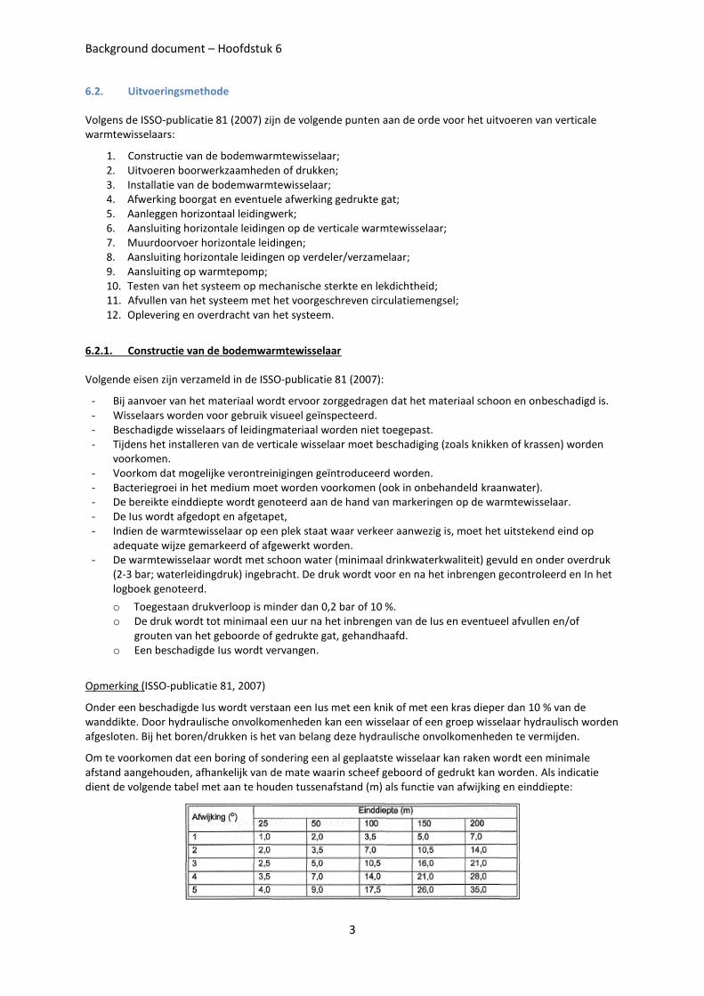
Om te voorkomen dat een boring of sondering een al geplaatste wisselaar kan raken wordt een minimale afstand aangehouden, afhankelijk van de mate waarin scheef geboord of gedrukt kan worden. Als indicatie dient de volgende tabel met aan te houden tussenafstand (m) als functie van afwijking en einddiepte:
Background document – Hoofdstuk 6
4
Constructie van bodem warmtewisselaars (ISSO-publicatie 81, 2007):
Polyethyleenbuis, minimaal klasse PE100 of gelijkwaardig; levensduur > 50 jaar onder de voorkomende bedrijfsomstandigheden en bij gebruik in de bodem. Dit materiaal kan worden toegepast indien de temperatuur van het door de buis stromende medium 50°C. Drukklassen worden gebruikt:
o Klasse PN8 SDR17 tot een diepte van 50 meter. o Klasse PN10 SDR13.6 voor grotere dieptes
U-Ius warmtewisselaars: geprefabriceerde en (druk-) geteste warmtewisselaars die bestaan uit twee leidingen aan de onderzijde verbonden door middel van een spuitgegoten PE bocht of gelijkwaardige verbinding. Het gebruikte PE materiaal dient conform KIWA BRL-K-533/02 of gelijkwaardige norm (bv SN218-306) gefabriceerd te zijn, en dient te zijn gemerkt (typeaanduiding, fabricagedatum, drukklasse, wanddikte).
Concentrische warmtewisselaars, geplaatst met een druktechniek waarbij de warmtewisselaar in een beschermde omgeving kan worden samengesteld, kunnen ter plaatse worden geconstrueerd indien wordt voldaan aan de NEN 7200 met betrekking tot stuiklassen.
Wisselaars dienen voorzien te zijn van een lengtemarkering (per meter), beginnend bij nul meter en naar boven oplopend zodat aan het maaiveld de totale lengte van de wisselaar gecontroleerd kan worden. De geïnstalleerde lengte van elke individuele wisselaar wordt gedocumenteerd. Wanneer er geen eenduidige lengtemarkering op de wisselaar is aangebracht wordt de geïnstalleerde diepte vastgesteld met behulp van een peillood.
Het wordt voor een U-Ius wisselaar aanbevolen afstandshouders tussen de benen te plaatsen, circa één per 3m. Afstand tussen de benen bedraagt globaal 0,05 - 0,07 m
Banks (2008)
U-tubes are usually made of high ,density polyethene (HDPE) tubing of diameter 32-40 mm (although medium density polyethene - MDPE - is sometimes used). A shank spacing (distance between the centres of the uphole and downhole tubes) of around 50- 60 mm is typical. Thus, the U-tube installation will have a width of 90- 100 mm. The diameter of boreholes drilled for closed·loop ground source heat schemes is typically around 125-130mm. To prevent thermal short-circuiting of heat between the upflow and downflow tubes, shank-spacers or clips should be placed down the length of the U-tube to maintain an acceptable shank spacing. The 'U' on the base of the tube is typically a pre-fabricated element and will usually be weighted to render emplacement of the tube into a water- or mud·-filled borehole easier. In water-filled borehole, there will also be buoyancy effects to overcome when emplacing the tube: the weighted 'U' may assist here, but it will usually also be necessary to fill the U-tube with water during emplacement.
Alternatives to U-tubes (Banks 2008): The ‘Double U’ tube has two upflow and two downflow tubes. It is somewhat more efficient than a ‘single U’, but very difficult to emplace in a borehole. Rosen et al. (2001) report the ‘vertical slinky’– a helical coil of tubing designed for emplacement in somewhat larger-diameter drilled boreholes.
Background document – Hoofdstuk 6
5
6.2.2. Uitvoeren boorwerkzaamheden of drukken
Europese richtlijnen m.b.t. het boren van geothermische systemen zijn gegeven in de ‘Geotrainet Training Manual for drillers’ (2011). De meest voorkomende boormethodes zijn beschreven hierna. De richtlijnen uit Nederland en de Verenigde Staten zijn ook in het kort gegeven.
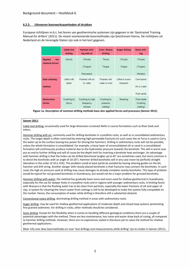
Figuur 1a. Description of common drilling methods base don applied forces and processes (Sanner 2011)
Sanner 2011:
Cable tool drilling: occasionally used for large dimension screened Wells in course formations such as River beds and eskers.
Hammer drilling with air: commonly used for drilling boreholes in crystalline rocks, as well as in consolidated sedimentary rocks. The target depth is often restricted by entering high permeable fractures (in such cases the air force is used to Carry the water up to the surface leaving less power for driving the hammer). Drilling in sedimentary rocks will not be possible, unless the whole formation is consolidated. For example, a loose layer of unconsolidated silt or sand in a consolidated formation will continuously produce material due to the hydrostatic pressure towards the borehole. This will in worst case put an end to further drilling and will of cause be the depth limit for inserting a borehole heat exchanger. An advantage with hammer drilling is that the holes can be drilled directional (angles up to 45° are sometimes used, but more common is to direct the boreholes with an angle of 10-20°). Hammer drilled boreholes will in any case never be perfectly straight (deviation in the order of 10 à 15%). This problem could at least partly be avoided by having steering guides on the bit, hammer and drill string. Another danger with closely placed boreholes is that fractures may connect the boreholes. In such cases the high air pressure used at drilling may cause damages to already complete nearby boreholes. This type of problem would be typical for not grouted boreholes in Scandinavia, but would not be a major problem for grouted boreholes.
Hammer drilling with water: the method has gradually been more and more used for shallow geothermal in Scandinavia, especially for the cse for deeper holes in crystalline rocks and in regions with younger sedimentary rocks. A limiting factor with Wassara is that the flushing water has to be clean from particles, especially the lower fractions of silt and upper of clay. A system for cleaning the return water from cuttings is still to be developed to make the system fully compatible on the market. Hence, the consumption of water while drilling is therefore still a substantial obstacle
Conventional rotary drilling: dominating drilling method in areas with sedimentary rocks.
Auger drilling: may be used for shallow geothermal applications of moderate depth and closed loop systems penetrating fine grained sediments. For drilling in rocks, other methods should be considered.
Sonic drilling: Except for the flexibility when it comes to handling different geological conditions there are a couple of potential advantages with the method. These are less maintenance, less noise and easier draw back of casing, all compared to hammer drilling methods. However, there are no experiences stated in literature yet to value the method for shallow geothermal applications.
Meer info over deze boormethodes en over ‘test drillings and measurements while drilling’ zijn te vinden in Sanner (2011).
Background document – Hoofdstuk 6
6
Volgende eisen/aanbevelingen zijn verzameld in de ISSO-publicatie 81 (2007):
- VCA-certificaat (Veiligheids Checklist Aannemers): opdrachtgevers kunnen het als eis stellen
- Indien geboord wordt is spoelboren of zuig-/luchtliftboren aan te bevelen.
- De overmaat bij boren/drukken dient zoveel mogelijk beperkt te worden.
- Bij boren zal een gangbare diameter, voor het plaatsen van een U-Ius, rand de 0,15 m liggen. - Bij drukken de overdiameter (drukkop, drukstang ten opzichte van de buitendiameter van de wisselaar)
beperken tot maximaal 0,03 m (anders kan een afdichting van het sondeergat noodzakelijk zijn).
Boren (ISSO-publicatie 81, 2007)
- Boormaterieel is door een bevoegde instantie gekeurd - Boorwerkzaamheden uitgevoerd door een bedrijf dat voldoet aan de EGB erkenningsregeling (Stichting Erkenning voor
het Grondboor- en Bronbemalingbedrijf) of vergelijkbare erkenningsregeling. - Voor een VBWW systeem liggen praktische dieptes op basis van een boortechniek tussen de 50 en 150 meter. De
diameter van het boorgat dient zo gekozen te worden dat de bodemwarmtewisselaar goed kan worden ingebouwd. - Diameter van het boorgat: zo klein mogelijk in verhouding tot de buitendiameter van de bodemwarmtewisselaar, maar
zodanig gekozen dat de Ius gemakkelijk kan worden ingebracht en het boorgat voldoende stabiel is (Normaal gesproken: tussen de 0,1 en 0,2 m, waarbij de over-diameter van het boorgat t.o.v. de buitendiameter van de lusconstructie 0,03 - 0,05 m.)
- De diameter van het boorgat mag niet meer dan ± 0,03 m variëren. - Per gebruikt oppervlakte van circa 50 x 50 meter wordt ten minste een boorbeschrijving gemaakt (conform de NEN5104).
Bij de boorbeschrijving worden ten minste de texturen en diepte van laagwisselingen aangegeven. - De booropstelling, met name de mast van de booropstelling, moet voldoende verticaal staan. boorstreng moet
voldoende gewicht hebben om verticaal te boren. Risico's op het mogelijk raken van een al geplaatste wisselaar moeten worden vermeden, zie ook specificatieblad 4.3-1. Bovendien moeten de wisselaars zoveel mogelijk op de juiste tussenafstand geplaatst worden voor een goede benutting van het bodemvolume.
- Indien noodzakelijk kan een casing gebruikt worden. Deze dient verwijderd te worden. - Het gebruikte werkwater is minimaal van een kwaliteit gelijk aan de kwaliteit van de aquifer. Wanneer werkwater in een
boorspoeling wordt gebruikt wordt dit gerecirculeerd of in elk geval opgevangen. De beschikbaarheid en kwaliteit van het werkwater worden met de opdrachtgever gecoördineerd.
- Het vrijkomend materiaal wordt gescheiden van het water. Het materiaal kan, mits de kwaliteit dit toelaat, op de bouwlocatie verwerkt worden. De kwaliteit van het materiaal wordt in overleg met de opdrachtgever of een door hem aangewezen persoon vastgesteld.
Afwerking boorgat (ISSO-publicatie 81, 2007)
- Indien het boorgat wordt gevuld met een (verpompbaar) water-bentonietmengsel (met mogelijke bijvullingen als cement of zand): o Het boorgat moet met behulp van een vulpijp (-slang) onder overdruk worden afgevuld met een geschikt
afvulmateriaal; o Het afvullen gebeurt van onder naar boven, waarbij de vulpijp steeds zover naar boven getrokken wordt dat de
uitstroomopening onder het niveau van het al aangebrachte afvulmateriaal blijft. Bij zeer diepe boorgaten kan het terugtrekken van de vulpijp problematisch zijn, dan kunnen twee vulpijpen worden toegepast: een diepe, die in het boorgat blijft en waarmee het boorgat tot ongeveer de helft wordt opgevuld, en een tweede pijp die tot de helft van het boorgat is ingebracht en kan worden teruggetrokken.
- Indien het boorgat wordt gevuld met zand of fijn grind mengsel (mogelijk noodzakelijke afdichting met bentoniet/klei korrels). o Het boorgat wordt met behulp van een valpijp afgevuld met een geschikt afvulmateriaal o Het afvullen gebeurt van onder naar boven, waarbij de valpijp in stages omhooggetrokken wordt. Er wordt tussen
de stages voldoende tijd gegund om het materiaal te laten bezinken. Eventuele afdichting van scheidende lagen met bentoniet korrels.
- Het totale volume (m³) verwerkt afvulmateriaal en de totale hoeveelheid gebruikte vaste delen (kg, per component) worden per boorgat gedocumenteerd.
- Een dag na het aanbrengen van het afdichtmateriaal wordt gecontroleerd in hoeverre het materiaal is ingezakt. Indien noodzakelijk wordt extra afvulmateriaal aangebracht.
Toelichting: Wanneer het vulmateriaal niet correct wordt aangebracht kunnen delen van het boorgat niet afgevuld zijn met afvulmateriaal, maar met voornamelijk water. Daarmee wordt de thermische prestatie negatief beïnvloed. Onjuiste afdichting kan ook de oorzaak zijn van het in contact brengen van bodemlagen met verschillende waterkwaliteit of kan kwel of risico op inzijging tot gevolg hebben.
Background document – Hoofdstuk 6
7
Drukken (ISSO-publicatie 81, 2007)
- De opstelling, met name de toren van de drukwagen, moet voldoende verticaal staan, de drukstreng moet voldoende
gewicht hebben om verticaal te drukken. Risico's op het mogelijk raken van een al geplaatste wisselaar moeten
worden vermeden. Bovendien moeten de wisselaars zoveel mogelijk op de juiste tussenafstand geplaatst worden voor
een goede benutting van het bodemvolume.
- Bij niet aanbrengen van afdichtmateriaal langs de bovenzijde vaststellen of er sprake is van kwel. Indien kwel optreedt
of op kan treden de bovenste 3 meter afdichten met bentoniet.
- Normaal gesproken zal de diameter van de drukstang tussen de 0,04 en 0,06 meter liggen. - De over-diameter van het drukgat zal niet groter zijn dan 0,01 - 0,03 m, maar is naast de stangdiameter ook
afhankelijk van de diameter van de gebruikte punt. - Per gebruikt oppervlakte van circa 50 x 50 meter wordt ten minste een log (weerstand en kleef) geregistreerd. - Toegepast materieel is door een bevoegde instantie gekeurd (bv conform 'EG verklaring van overeenstemming voor
machines', richtlijn 98/37EG). - Voor een VBWW systeem liggen praktische dieptes op basis van een druktechniek tussen de 20 en 50 meter.
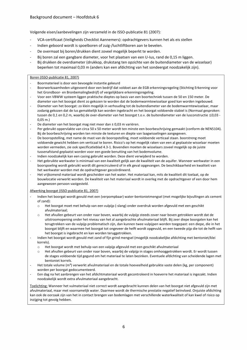
(a) (b)
(c) (d) (e)
Figure 1b (a) Air drilling method (Sanner 2011); (b) Wet/Mud Rotary Drill Rig (IGHSPA 2009); (c-d) rotary drilling method (Sanner 2011); (e) Auger drilling
Background document – Hoofdstuk 6
8
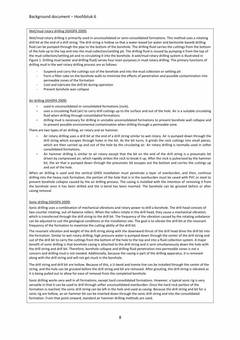
Wet/mud rotary drilling (IGHSPA 2009)
Wet/mud rotary drilling is primarily used in unconsolidated or semi-consolidated formations. This method uses a rotating drill bit at the end of a drill string. The drill string is hollow so that a water-based (or water and bentonite-based) drilling fluid can be pumped through the pipe to the bottom of the borehole. The drilling fluid carries the cuttings from the bottom of the hole up to the top and into the mud collection/settling pit. The drilling fluid is reused by pumping it from the top of the mud collection/settling pit and re-circulating it into the borehole. A wet/mud rotary drilling system is illustrated in Figure 1. Drilling mud (water and drilling fluid) serves four main purposes in mud-rotary drilling. The primary functions of drilling mud in the wet rotary drilling process are as follows:
- Suspend and carry the cuttings out of the borehole and into the mud collection or settling pit - Form a filter cake on the borehole walls to minimize the effects of penetration and possible contamination into
permeable zones of the formation - Cool and lubricate the drill bit during operation - Prevent borehole wan collapse
Air drilling (IGHSPA 2009)
used in unconsolidated or consolidated formations (rock).
uses a circulating fluid (air) to carry drill cuttings up to the surface and out of the hole. Air is a suitable circulating fluid when drilling through consolidated formations.
drilling mud is necessary for drilling in unstable unconsolidated formations to prevent borehole wall collapse and to prevent possible environmental contamination when drilling through a permeable zone.
There are two types of air drilling, air rotary and air hammer.
Air rotary drilling uses a drill bit at the end of a drill string similar to wet rotary. Air is pumped down through the drill string which escapes through holes in the bit. As the bit turns, it grinds the rock cuttings into small pieces, which are then carried up and out of the hole by the circulating air. Air rotary drilling is normally used in softer consolidated formations.
Air hammer drilling is similar to air rotary except that the bit on the end of the drill string is a pneumatic bit driven by compressed air, which rapidly strikes the rock to break it up. After the rock is pulverized by the hammer bit, the air that is pumped down through the pneumatic bit escapes out the bottom and carries the cuttings up and out of the hole.
When air drilling is used and the vertical GHEX installation must penetrate a layer of overburden, and then, continue drilling into the heavy rock formation, the portion of the hole that is in the overburden must be cased with PVC or steel to prevent borehole collapse caused by the air drilling process. The casing is installed with the intention of removing it from the borehole once it has been drilled and the U-bend has been inserted. The borehole can be grouted before or after casing removal.
Sonic drilling (IGHSPA 2009)
Sonic drilling uses a combination of mechanical vibrations and rotary power to drill a borehole. The drill head consists of two counter rotating, out-of-balance rollers. When the rollers rotate in the drill head, they cause a mechanical vibration, which is transferred through the drill string to the drill bit. The frequency of the vibration caused by the rotating unbalance can be adjusted to suit the geological conditions at the installation site. The goal is to vibrate the drill bit at the resonant frequency of the formation to maximize the cutting ability of the drill bit.
The resonant vibration and weight of the drill string along with the downward thrust of the drill head drive the drill bit into the formation. Similar to wet rotary drilling, high pressure water is pumped down through the center of the drill string and out of the drill bit to carry the cuttings from the bottom of the hole to the top and into a fluid collection system. A major benefit of sonic drilling is that borehole casing is attached to the drill string and is sent simultaneously down the hole with the drill string and drill bit. Therefore, borehole collapse and drilling fluid penetration into permeable zones is not a concern and drilling mud is not needed. Additionally, because the casing is part of the drilling apparatus, it is removed along with the drill string and will not get stuck in the borehole.
The drill string and drill bit are hollow. Because of this, a U-bend and tremie line can be installed through the center of the string, and the hole can be grouted before the drill string and bit are removed. After grouting, the drill string is vibrated as it is being pulled out to allow for ease of removal from the completed borehole.
Sonic drilling works very well in all formations, except hard consolidated formations. However, a typical sonic rig is very versatile in that it can be used to drill through softer unconsolidated overburden. Once the hard rock portion of the formation is reached, the sonic drill string can be left in the hole and used as casing. Because the drill string and bit for a sonic rig are hollow, an air hammer bit can be inserted down through the sonic drill string and into the consolidated formation. From that point onward, standard air hammer drilling methods are used.
Background document – Hoofdstuk 6
9
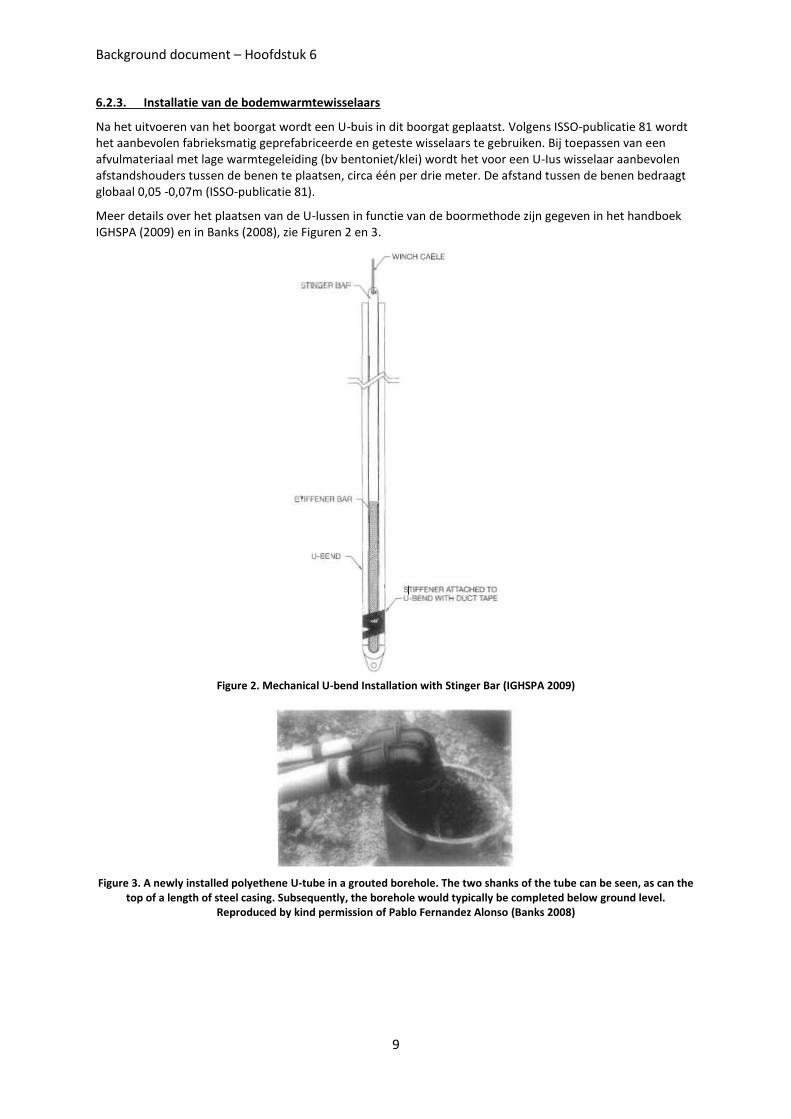
6.2.3. Installatie van de bodemwarmtewisselaars
Na het uitvoeren van het boorgat wordt een U-buis in dit boorgat geplaatst. Volgens ISSO-publicatie 81 wordt het aanbevolen fabrieksmatig geprefabriceerde en geteste wisselaars te gebruiken. Bij toepassen van een afvulmateriaal met lage warmtegeleiding (bv bentoniet/klei) wordt het voor een U-Ius wisselaar aanbevolen afstandshouders tussen de benen te plaatsen, circa één per drie meter. De afstand tussen de benen bedraagt globaal 0,05 -0,07m (ISSO-publicatie 81).
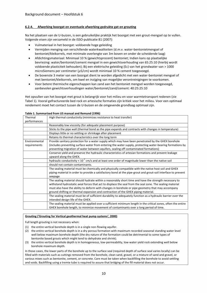
Meer details over het plaatsen van de U-lussen in functie van de boormethode zijn gegeven in het handboek IGHSPA (2009) en in Banks (2008), zie Figuren 2 en 3.
Figure 2. Mechanical U-bend Installation with Stinger Bar (IGHSPA 2009)
Figure 3. A newly installed polyethene U-tube in a grouted borehole. The two shanks of the tube can be seen, as can the top of a length of steel casing. Subsequently, the borehole would typically be completed below ground level.
Reproduced by kind permission of Pablo Fernandez Alonso (Banks 2008)
Background document – Hoofdstuk 6
10
6.2.4. Afwerking boorgat en eventuele afwerking gedrukte gat en grouting
Na het plaatsen van de U-buizen, is een gebruikelijke praktijk het boorgat met een grout-mengsel op te vullen. Volgende eisen zijn verzameld in de ISSO-publicatie 81 (2007):
Vulmateriaal in het boorgat: voldoende hoge geleiding
Vermijden menging van verschillende waterkwaliteiten (d.m.v. water-bentonietmengsel of bentoniet/kleikorrels, met minimale overlengte van 3m boven en onder de scheidende laag)
Afdichtingsmateriaal: Minimaal 10 % (gewichtsprocent) bentoniet; Indien kans op plaatselijke bevriezing: water/bentoniet/cement mengsel in een gewichtsverhouding van 65:25:10 (hierbij wordt voldoende plasticiteit behouden); Bij een elektrische geleiding (Ec) van het grondwater van > 1000 microSiemens per centimeter ( S/cm) wordt minimaal 10 % cement toegevoegd.
De bovenste 3 meter van een boorgat dient te worden afgedicht met een water-bentoniet mengsel of met bentoniet/kleikorrels, om kwel en inzijging van mogelijke verontreinigingen te voorkomen.
Voor betere thermische eigenschappen kan zand aan het bentoniet mengsel worden toegevoegd, aanbevolen gewichtsverhoudingen water/bentoniet/zand/cement: 40:25:25:10
Het opvullen van het boorgat met grout is belangrijk voor het milieu en voor warmtetransport redenen (zie Tabel 1). Vooral gefractureerde bed rock en artesische formaties zijn kritiek voor het milieu. Voor een optimaal rendement moet het contact tussen de U-buizen en de omgevende grondlaag optimaal zijn.
Table 1. Summarized from US manual and Remund (1996)
Thermal performances
High thermal conductivity (minimizes resistance to heat transfer)
Reasonably low viscosity (for adequate placement purpose)
Sticks to the pipe wall (thermal bond as the pipe expands and contracts with changes in temperature)
Displays little or no settling or shrinkage after placement
Retains its thermal characteristics over the long term
Environmental requirements
Provide sanitary protection for a water supply which may have been penetrated by the GHEX borehole (includes preventing surface water from entering the water supply, protecting water-bearing formations by preventing migration of water between aquifers, sealing off contaminated formations)
Conserve yield and preserve the hydraulic characteristics of artesian formations and prevent leakage upward along the GHEX.
hydraulic conductivity < 10-7
cm/s and at least one order of magnitude lower than the native soil
should not contain contaminants.
The sealing material must be chemically and physically compatible with the native host soil and GHEX piping material in order to provide a satisfactory bond at the pipe-grout and grout-soil interface to prevent seepage
The sealing material should hydrate within a reasonably short time and have the strength necessary to withstand hydrostatic axial forces that act to displace the seal from the seal zone. The sealing material must also have the ability to deform with changes in borehole or pipe geometry that may accompany ground shifting or thermal expansion and contraction of the GHEX piping material.
The sealing material must be of sufficient durability to adequately function as a hydraulic barrier over the intended design life of the GHEX.
The sealing material must be applied over a sufficient minimum length in the critical zones, often the entire GHEX borehole length, to minimize movement of contaminants over a long period of time.
Grouting (‘Grouting for Vertical geothermal heat pump systems’, 2000)
Full length grouting is not necessary when:
(1) the entire vertical borehole depth is in a single non-flowing aquifer. (2) the entire vertical borehole depth is in a dry porous formation with maximum recorded seasonal standing water level
well below maximum borehole depth (the dry nature of the formation could be detrimental to some types of bentonite based grouts which might tend to dehydrate and shrink).
(3) the entire vertical borehole depth is in homogeneous, low-permeability, low-water yield rock extending well below borehole maximum depth.
In those cases, the lower parts of the borehole up to the surface seal (required depth of surface seal varies locally) can be filled with materials such as cuttings removed from the borehole, clean sand, gravel, or a mixture of sand and gravel, or various mixes such as bentonite, cement, or concrete. Care must be taken when backfilling the borehole to avoid settling and voids. Backfilling using a tremie tube is required to assure that bridging of the fill material does not occur.
Background document – Hoofdstuk 6
11
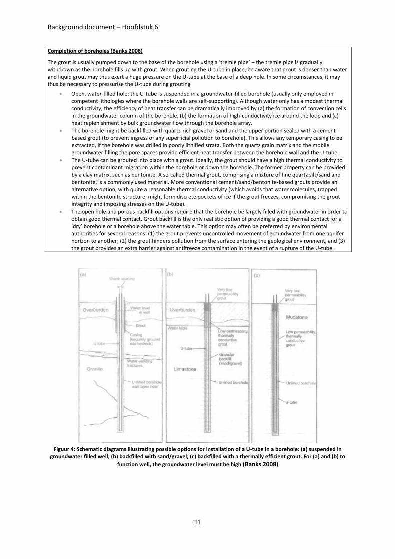
Completion of boreholes (Banks 2008)
The grout is usually pumped down to the base of the borehole using a ‘tremie pipe’ – the tremie pipe is gradually withdrawn as the borehole fills up with grout. When grouting the U-tube in place, be aware that grout is denser than water and liquid grout may thus exert a huge pressure on the U-tube at the base of a deep hole. In some circumstances, it may thus be necessary to pressurise the U-tube during grouting
Open, water-filled hole: the U-tube is suspended in a groundwater-filled borehole (usually only employed in competent lithologies where the borehole walls are self-supporting). Although water only has a modest thermal conductivity, the efficiency of heat transfer can be dramatically improved by (a) the formation of convection cells in the groundwater column of the borehole, (b) the formation of high-conductivity ice around the loop and (c) heat replenishment by bulk groundwater flow through the borehole array.
The borehole might be backfilled with quartz-rich gravel or sand and the upper portion sealed with a cement-based grout (to prevent ingress of any superficial pollution to borehole). This allows any temporary casing to be extracted, if the borehole was drilled in poorly lithified strata. Both the quartz grain matrix and the mobile groundwater filling the pore spaces provide efficient heat transfer between the borehole wall and the U-tube.
The U-tube can be grouted into place with a grout. Ideally, the grout should have a high thermal conductivity to prevent contaminant migration within the borehole or down the borehole. The former property can be provided by a clay matrix, such as bentonite. A so-called thermal grout, comprising a mixture of fine quartz silt/sand and bentonite, is a commonly used material. More conventional cement/sand/bentonite-based grouts provide an alternative option, with quite a reasonable thermal conductivity (which avoids that water molecules, trapped within the bentonite structure, might form discrete pockets of ice if the grout freezes, compromising the grout integrity and imposing stresses on the U-tube).
The open hole and porous backfill options require that the borehole be largely filled with groundwater in order to obtain good thermal contact. Grout backfill is the only realistic option of providing a good thermal contact for a ‘dry’ borehole or a borehole above the water table. This option may often be preferred by environmental authorities for several reasons: (1) the grout prevents uncontrolled movement of groundwater from one aquifer horizon to another; (2) the grout hinders pollution from the surface entering the geological environment, and (3) the grout provides an extra barrier against antifreeze contamination in the event of a rupture of the U-tube.
Figuur 4: Schematic diagrams illustrating possible options for installation of a U-tube in a borehole: (a) suspended in
groundwater filled well; (b) backfilled with sand/gravel; (c) backfilled with a thermally efficient grout. For (a) and (b) to
function well, the groundwater level must be high (Banks 2008)
Background document – Hoofdstuk 6
12
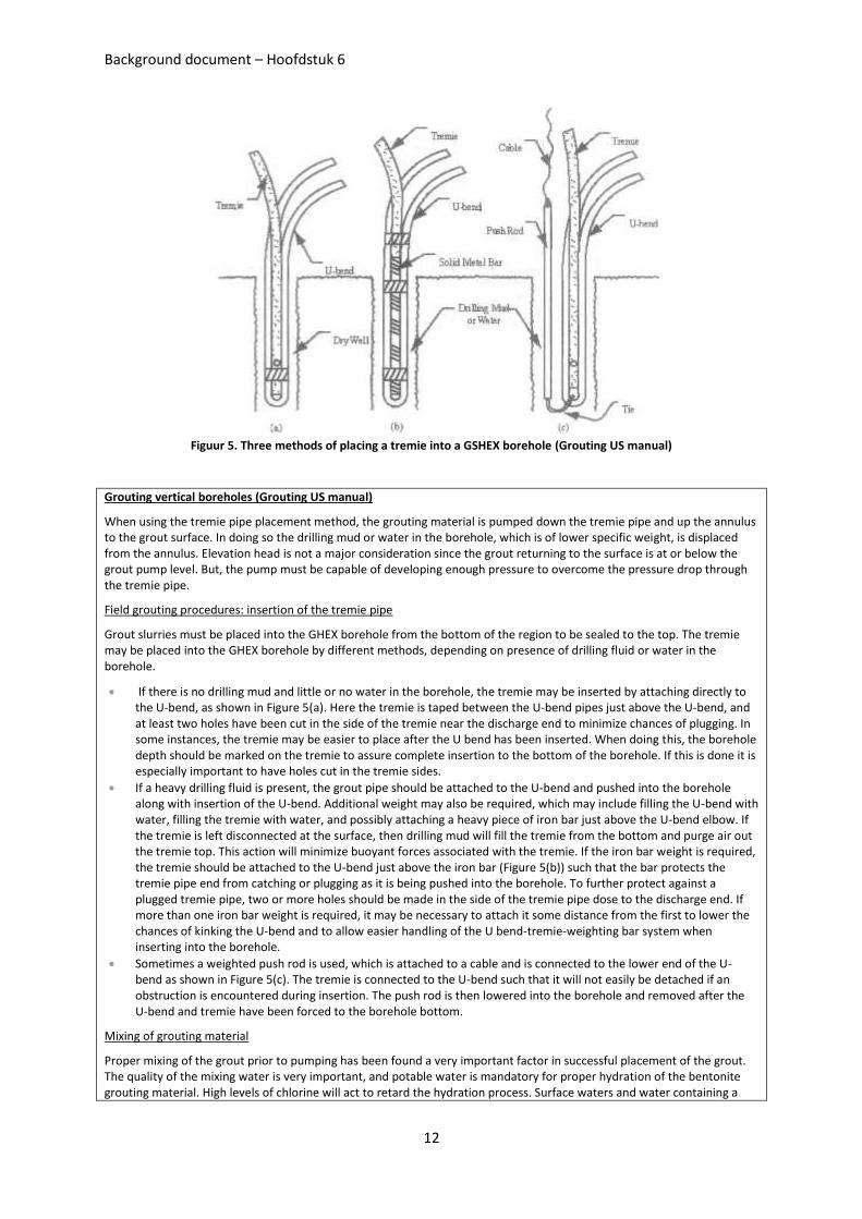
Figuur 5. Three methods of placing a tremie into a GSHEX borehole (Grouting US manual)
Grouting vertical boreholes (Grouting US manual)
When using the tremie pipe placement method, the grouting material is pumped down the tremie pipe and up the annulus to the grout surface. In doing so the drilling mud or water in the borehole, which is of lower specific weight, is displaced from the annulus. Elevation head is not a major consideration since the grout returning to the surface is at or below the grout pump level. But, the pump must be capable of developing enough pressure to overcome the pressure drop through the tremie pipe.
Field grouting procedures: insertion of the tremie pipe
Grout slurries must be placed into the GHEX borehole from the bottom of the region to be sealed to the top. The tremie may be placed into the GHEX borehole by different methods, depending on presence of drilling fluid or water in the borehole.
If there is no drilling mud and little or no water in the borehole, the tremie may be inserted by attaching directly to the U-bend, as shown in Figure 5(a). Here the tremie is taped between the U-bend pipes just above the U-bend, and at least two holes have been cut in the side of the tremie near the discharge end to minimize chances of plugging. In some instances, the tremie may be easier to place after the U bend has been inserted. When doing this, the borehole depth should be marked on the tremie to assure complete insertion to the bottom of the borehole. If this is done it is especially important to have holes cut in the tremie sides.
If a heavy drilling fluid is present, the grout pipe should be attached to the U-bend and pushed into the borehole along with insertion of the U-bend. Additional weight may also be required, which may include filling the U-bend with water, filling the tremie with water, and possibly attaching a heavy piece of iron bar just above the U-bend elbow. If the tremie is left disconnected at the surface, then drilling mud will fill the tremie from the bottom and purge air out the tremie top. This action will minimize buoyant forces associated with the tremie. If the iron bar weight is required, the tremie should be attached to the U-bend just above the iron bar (Figure 5(b)) such that the bar protects the tremie pipe end from catching or plugging as it is being pushed into the borehole. To further protect against a plugged tremie pipe, two or more holes should be made in the side of the tremie pipe dose to the discharge end. If more than one iron bar weight is required, it may be necessary to attach it some distance from the first to lower the chances of kinking the U-bend and to allow easier handling of the U bend-tremie-weighting bar system when inserting into the borehole.
Sometimes a weighted push rod is used, which is attached to a cable and is connected to the lower end of the U-bend as shown in Figure 5(c). The tremie is connected to the U-bend such that it will not easily be detached if an obstruction is encountered during insertion. The push rod is then lowered into the borehole and removed after the U-bend and tremie have been forced to the borehole bottom.
Mixing of grouting material
Proper mixing of the grout prior to pumping has been found a very important factor in successful placement of the grout. The quality of the mixing water is very important, and potable water is mandatory for proper hydration of the bentonite grouting material. High levels of chlorine will act to retard the hydration process. Surface waters and water containing a
Background document – Hoofdstuk 6
13
high dissolved mineral content should not be used since they might adversely affect performance of the grouting material. Temperature of the mixing water is also very important, and should be kept as low as possible to prevent rapid hydration of the bentonite grout. If mixing water is to be kept in a storage tank on-site, it should be kept shaded from the sun or the tank should have a reflective surface to minimize water temperature increase prior to use. The warmer the mixing water, the more rapid the rate of hydration and the higher the pumping pressure will be at a given pumping rate.
If a thermally-enhanced grouting material is to be used, the mixing directions provided by the manufacturer must be followed. If excessive water is used, the mixture will become too thin and the thermal enhancement material will be difficult to hold in suspension. In this case, the target thermal conductivity of the thermally-enhanced grout will not be met, and the GHEX will not work as well as the designer had planned for in the specifications. In addition, too much water will result in a grout of higher than expected permeability. If water is below the recommended amount, the mixture will become very thick and will be very difficult, if not impossible, to pump. With thermally-enhanced grouts it is especially important that a water meter is used to assure that the amount of mix water that is placed in the grout mixing tank meets manufacturer’s recommendations.
Grout mixing can be the limiting factor in the efficiency of the grouting procedure. If the grouting material cannot be mixed as fast as it can be pumped, the grout pump will have to be slowed down or periodically shut down while waiting for the next batch of grout to be completely mixed. Incomplete mixing of the grout to speed the entire process may result in “dry dumps” of bentonite being forced ,through the tremie pipe. This will create excessive pressures in the pumping process and non-uniform hydration of the grouting material. If mixing is the limiting factor the pump may be shut down between batches, but this should be done with care to assure that the grout is not allowed time to set up in the tremie pipe. It is always best to keep the grout flowing and minimize opportunity for thickening of the grout One solution to the problem would be an intermediate holding tank to serve as a reservoir to the pump suction inlet. The holding tank should have a stirrer to delay thickening of the bentonite with agitation. A second option is to have two mixing tanks, which would double the mixing capacity of the system. But, this may require another person and add to the labor costs of the grouting procedure.
Pumping the grouting material
Selection of the appropriate grout pump is the most important factor in the development of an efficient and effective grouting procedure. The pressure being developed by the pump is important during placement of the grouting material as a quality control measure that indicates if the grout is being mixed properly. If the pumping pressure is higher than normal, it may be that the mix water is too warm or that the grout is being mixed at a higher than normal solids content. If the pumping pressure is lower than normal the grout may have been mixed with too much water, producing a lower than expected solids content that may not adequately perform the grouting function.
Removal of the tremie pipe
After the tremie has been placed into the borehole, pumping of the grout may begin. In stable formations, where the borehole will remain open for extended periods of time, the pumping procedure need not be done right away but should be completed during the same day. In unstable formations, where the borehole may cave or slough, the grout should be pumped immediately following placement of the tremie pipe. In either case, after the first batch is pumped into the borehole, the tremie should be pulled at about the same rate that grout is filling the borehole. This will minimize hydrostatic head on the tremie outlet and reduce any chances of the tremie being stuck in the borehole due to hydration of the grout. But, the outlet end of the tremie pipe should be kept below the grout level at all times.
Other grouting considerations
Proper completion of each borehole requires that grout leave the top of the borehole with the same weight and consistency as is being pumped into the tremie. For holes containing drilling mud or water, this will only be accomplished by completely grouting the borehole from bottom to top. When grouting in this manner, only one borehole per grouting session will be completed, and the grouting equipment will have to be cleaned after every borehole. In some cases it may be possible to completely grout the borehole and move directly to the next borehole without cleaning the equipment. This allows for two or more boreholes to be grouted consecutively, but requires that the grout-filled tremie can be placed into the borehole after the U-bend has already been inserted. In the case of extremely stable borehole, it may be possible to drill several boreholes prior to grouting, with a U-bend and tremie pair placed into each immediately after drilling. In this case several boreholes can be drilled and then grouted with a predetermined volume of grout, and after the final borehole is completely grouted the previous boreholes can then be "topped off." This method would be the most efficient, but does require stable boreholes to assure that the tremie pipes eau be removed from the boreholes.
More details on pump selection, grout mixing equipment selection, grout volume calculation, grouting cost estimation, field grouting procedures in the US manual.
Background document – Hoofdstuk 6
14
Appropriate grouting materials (‘Grouting for Vertical geothermal heat pump systems, 2000’)
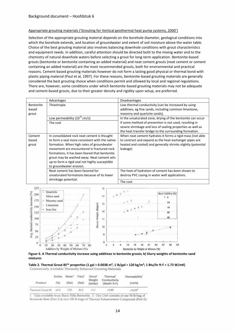
Selection of the appropriate grouting material depends on the borehole diameter, geological conditions into which the borehole extends, and location of groundwater and extent of soil moisture above the water table. Choice of the best grouting material also involves balancing downhole conditions with grout characteristics and equipment needs. In addition, careful attention should be directed both to the mixing water and to the chemistry of natural downhole waters before selecting a grout for long-term application. Bentonite-based grouts (bentonite or bentonite containing an added material) and neat cement grouts (neat cement or cement containing an added material) are the most recommended grouts, both for environmental and practical reasons. Cement-based grouting materials however do not form a lasting good physical or thermal bond with plastic piping material (Paul et al, 1997). For these reasons, bentonite-based grouting materials are generally considered the best grouting choice when conditions permit and allowed by local and regional regulations. There are, however, some conditions under which bentonite-based grouting materials may not be adequate and cement-based grouts, due to their greater density and rigidity upon setup, are preferred.
Advantages Disadvantages
Bentonite based grout
Thixotropie Low thermal conductivity (can be increased by using additives, eg fine sands, including common limestone, masonry and quartzite sands).
Low permeability (10-8
cm/s) In the unsaturated zone, drying of the bentonite can occur if some method of prevention is not used, resulting in severe shrinkage and loss of sealing properties as well as the heat transfer bridge to the surrounding formation.
The cost
Cement based grout
In consolidated rock neat cement is thought to form a seal more consistent with the native formation. When high rates of groundwater movement are encountered in fractured rock formations, it has been feared that bentonite grout may be washed away. Neat cement sets up to form a rigid seal not highly susceptible to groundwater erosion.
When neat cement hydrates it forms a rigid mass (not able to contract and expand as the heat exchanger pipes are heated and cooled) and generally shrinks slightly (potential leakage)
Neat cement has been favored for unsaturated formations because of its lower shrinkage potential.
The heat of hydration of cement has been shown to destroy PVC casing in water well applications.
The cost
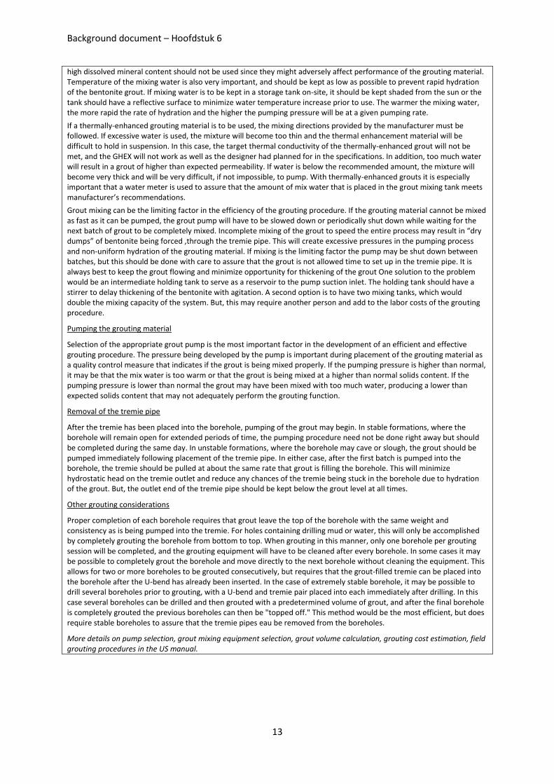
Figuur 6. A Thermal conductivity increase using additives in bentonite grouts; b) Slurry weights of bentonite-sand mixtures
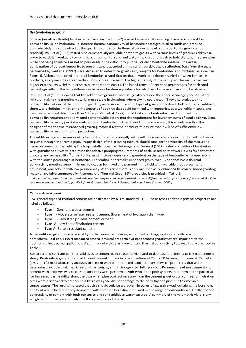
Table 2. Thermal Grout 8S™ properties (1 gal = 0.0038 m³, 1 lb/gal = 120 kg/m³; 1 Btu/hr ft F = 1.73 W/mK)
Background document – Hoofdstuk 6
15
Bentonite-based grout
Sodium (montmorillonite) bentonite (or “swelling bentonite”) is used because of its swelling characteristics and low permeability up on hydration. To increase thermal conductivity of bentonite based grout, silica sands can produce approximately the same effect as the quartzite sand (double thermal conductivity of a pure bentonite grout can be reached). Paul et al (1997) tested nine commercially available bentonite grouts with various levels of granular additive in order to establish workable combinations of bentonite, sand and water (i.e. viscous enough to hold the sand in suspension while not being so viscous as not to pour easily or be difficult to pump). For each bentonite material, the actual combination of percent bentonite to percent sand depended on the sand's particle size distribution. Data from the tests performed by Paul et al (1997) were also used to determine grout slurry weights for bentonite-sand mixtures, as shown in Figure 6. Although the combination of bentonite to sand that produced workable mixtures varied between bentonite products, slurry weights agreed within limits of measurement. The higher density of the sand particles resulted in much higher grout slurry weights relative to pure bentonite grouts. The broad range of bentonite percentages for each sand percentage reflects the large differences between bentonite products for which workable mixtures could be obtained.
Remund et al (1993) showed that the addition of granular material greatly reduced the linear shrinkage potential of the mixture, making the grouting material more stable in situations where drying could occur. They also evaluated the permeabilities of one of the bentonite grouting materials with several types of granular additives. Independent of additive, there was a definite limitation to the amount of additive that could be mixed with bentonite, as a workable mixture, and maintain a permeability of less than 10
-7cm/s. Paul et al (1997) found that some bentonites could not meet the
permeability requirement at any sand content while others met the requirement for lower amounts of sand additive. Since permeability for every possible combination of bentonite and sand could not be measured, it is mandatory that the designer of the thermally-enhanced grouting material test their product to ensure that it will be of sufficiently low permeability for environmental protection.
The addition of granular material to the bentonite slurry generally will result in a more viscous mixture that will be harder to pump through the tremie pipe. Proper design of the grouting mixture should consider the viscosity of the mixture to make placement in the field by the loop installer possible. Heiberger and Remund (1997) tested viscosities of bentonites with granular additives to determine the relative pumping requirements of each. Based on that work it was found that the viscosity and pumpability
(*) of bentonite-sand mixtures were very dependent on the type of bentonite being used along
with the mixed percentage of bentonite. The workable thermally-enhanced grout, then, is one that has a thermal conductivity meeting some minimum value, can be mixed and pumped in the field with available grout placement equipment, and sets up with low permeability. At this time there is only one thermally-enhanced bentonite-based grouting material available commercially. A summary of Thermal Grout 8S™ properties is provided in Table 2. (*) the pumping properties are determined based on the pressure drop observed through different tremie pipe sizes as a function of the flow rate and pumping time (see Appendix B from ‘Grouting for Vertical Geothermal Heat Pump Systems 2000’)
Cement-based grout
Five general types of Portland cement are designated by ASTM standard C150. These types and their general properties are listed as follows:
Type I - General purpose cement
Type II - Moderate sulfate resistant cement (lower heat of hydration than Type I)
Type III - Early strength development cement
Type IV - Low heat of hydration cement
Type V - Sulfate resistant cement
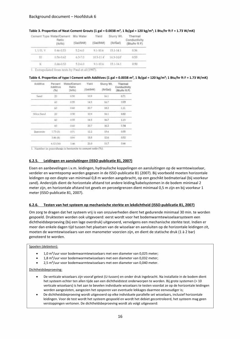
A cementitious grout is a mixture of hydraulic cement and water, with or without aggregates and with or without admixtures. Paul et al (1997) measured several physical properties of neat cement grouts that are important to the geothermal heat pump application. A summary of yield, slurry weight and thermal conductivity test results are provided in Table 3.
Bentonite and sand are common additives to cement to increase the yield and to decrease the density of the neat cement slurry. Bentonite is generally added to neat cement slurries in concentrations of 2% to 8% by weight of cement. Paul et al (1997) performed laboratory analyses of cement with bentonite and sand additives. Physical properties that were determined included volumetric yield, slurry weight, and shrinkage after full hydration. Permeability of neat cement and cement with additives was discussed, and tests were performed with embedded pipe systems to determine the potential for increased permeability along the pipe when pipe contraction away from the cement grout occurred. Heat of hydration tests were performed to determine if there was potential for damage to the polyethylene pipe due to excessive temperatures. The results indicated that this should only be a problem in zones of excessive washout along the borehole, and heat would be sufficiently dissipated with common bore diameters and over a range of soil conditions. Finally, thermal conductivity of cement with both bentonite and sand additives was measured. A summary of the volumetric yield, slurry weight and thermal conductivity results is provided in Table 4.
Background document – Hoofdstuk 6
16
Table 3. Properties of Neat Cement Grouts (1 gal = 0.0038 m³, 1 lb/gal = 120 kg/m³; 1 Btu/hr ft F = 1.73 W/mK)
Table 4. Properties of type I Cement with Additives (1 gal = 0.0038 m³, 1 lb/gal = 120 kg/m³; 1 Btu/hr ft F = 1.73 W/mK)
6.2.5. Leidingen en aansluitingen (ISSO-publicatie 81, 2007)
Eisen en aanbevelingen i.v.m. leidingen, hydraulische koppelingen en aansluitingen op de warmtewisselaar, verdeler en warmtepomp worden gegeven in de ISSO-publicatie 81 (2007). Bij voorbeeld moeten horizontale leidingen op een diepte van minimaal 0,8 m worden aangebracht, op een geschikt bedmateriaal (bij voorkeur zand). Anderzijds dient de horizontale afstand tot andere leiding/kabelsystemen in de bodem minimaal 2 meter zijn, en horizontale afstand tot gevels en perceelgrenzen dient minimaal 0,5 m zijn en bij voorkeur 1 meter (ISSO-publicatie 81, 2007).
6.2.6. Testen van het systeem op mechanische sterkte en lekdichtheid (ISSO-publicatie 81, 2007)
Om zorg te dragen dat het systeem vrij is van onzuiverheden dient het gedurende minimaal 30 min. te worden gespoeld. Druktesten worden ook uitgevoerd: eerst wordt voor het bodemwarmtewisselaarsysteem een dichtheidsbeproeving (bij een lage overdruk) uitgevoerd, vervolgens een mechanische sterkte test. Indien er meer dan enkele dagen tijd tussen het plaatsen van de wisselaar en aansluiten op de horizontale leidingen zit, moeten de warmtewisselaars van een manometer voorzien zijn, en dient de statische druk (1 à 2 bar) genoteerd te worden.
Spoelen (debieten):
1,0 m³/uur voor bodemwarmtewisselaars met een diameter van 0,025 meter;
1,8 m³/uur voor bodemwarmetwisselaars met een diameter van 0,032 meter;
2,5 m³/uur voor bodemwarmtewisselaars met een diameter van 0,040 meter.
Dichtheidsbeproeving:
De verticale wisselaars zijn vooraf getest (U-Iussen) en onder druk ingebracht. Na installatie in de bodem dient het systeem echter ten allen tijde aan een dichtheidstest onderworpen te worden. Bij grote systemen (> 10 verticale wisselaars) is het aan te bevelen individuele wisselaars te testen voordat ze op de horizontale leidingen worden aangesloten, aangezien het opsporen van eventuele lekkages daarmee eenvoudiger is;
De dichtheidsbeproeving wordt uitgevoerd op elke individuele parallelle set wisselaars, inclusief horizontale leidingen. Voor de test wordt het systeem gespoeld en wordt het debiet gecontroleerd, het systeem mag geen verstoppingen vertonen. De dichtheldsbeproeving wordt als volgt uitgevoerd:
Background document – Hoofdstuk 6
17
1) Dichtheidsbeproeving op een inwendige druk van ca. 0,05 MPa (0,5 bar). Hierbij worden lekkages In foutief gemonteerde verbindingen eerder opgespoord dan bij hoge druk (waarbij de Ius tegen de mot dichtgedrukt kan worden). Het systeem wordt visueel geïnspecteerd;
2) Wanneer na 1 uur een maximale drukvermindering van minder dan 0,01 MPa (0,1 bar) is geconstateerd, dan wordt de druk opgevoerd tot de bedrijfsdruk. Aangezien de bedrijfsdruk normaal gesproken ongeveer 0,2 - 0,3 MPa (2 - 3 bar) bedraagt wordt de druk in twee stappen van 30 minuten opgevoerd;
3) Het systeem wordt visueel geïnspecteerd. Wanneer na 1 uur een maximale drukvermindering van minder dan 0,01 MPa (0,1 bar) is geconstateerd dan is de leiding dicht en kan het systeem op sterkte beproefd worden.
Mechanische sterktetest: De sterktetest wordt uitgevoerd bij minimaal 80 % van de drukklasse (PN8: 6,4 bar, PN 10:8 bar), gedurende een uur mag de druk niet meer dan 10 % dalen.
Drukverlies: Het drukverlies over het systeem is bekend, want dit is bij het ontwerp berekend. Wanneer, bij een gespecificeerd debiet, het drukverlies veel lager is dan is dat een indicatie van een mogelijke kortsluiting (onjuiste verbinding). Is het drukverlies veel hoger dan is dat een indicatie van een verstopping of van een niet aangesloten (of hydraulisch afgesloten) verticale wisselaar.
6.2.7. Afvullen van het systeem met het voorgeschreven circulatiemengsel
Eisen en aanbevelingen i.v.m het circulatiemengsel worden ook gegeven in de ISSO-publicatie 81 (2007).
Kwaliteitseisen circulatiemedium
Ontwerp medium Temperatuur
- -5°C (Iaagst toelaatbare gemiddelde temperatuur van aanvoer en retour na 25 jaar). - Max +40 °c tijdens toevoer van zonnewarmte. - Max +30 °c tijdens actieve koeling (anders wordt de buitenlucht aantrekkelijker als koelmedium).
Debiet bodemwarmtewisselaars
Wanneer het debiet over individuele wisselaars niet apart ingeregeld kan worden dienen de wisselaars niet teveel in onderlinge lengte af te wijken (max 10 %). Toelichting: Bij grotere lengteverschillen kan, door verschillend drukverlies, een wisselaar hydraulisch worden afgesloten. Opmerking: Ook door hydraulische onvolkomenheden kan een wisselaar of een groep wisselaar hydraulisch worden afgesloten. Bij het boren/drukken is het van belang deze hydraulische onvolkomenheden te vermijden.
Afvullen systeem
Water-glycol mengsel met < 25 % glycol: dient te worden behandeld met een biocide om bacteriegroei te voorkomen (bij bacteriële afbraak van glycol worden namelijk zuren gevormd die corrosie bevorderen) en voldoende tegen corrosie geïnhibeerd. Het gebruikte water voldoet aan de specificaties van de leverancier van het antivriesmiddel. De componenten worden in een mengvat gemengd en in het systeem geïntroduceerd, of het geïnhibeerde glycol wordt aan de bodemwarmtewisselaar toegevoerd terwijl gecirculeerd wordt (over een mengvat). Bijvullen van het met water gevulde wisselaarsysteem voldoet niet (er treedt niet snel genoeg voldoende menging op).
Vriespunt van het circulatiemengsel
De bescherming tegen bevriezing van het medium dient minimaal 3 K onder de laagst optredende ontwerp mediumtemperatuur te liggen (uittrede verdamper). Opmerking: Bovenstaand punt in combinatie met een ontwerpmediumtemperatuur niet lager dan -5°C betekent: een vorstbeveiliging tot minstens -10°C.
Aanbevelingen
Ontwerpmedium temperatuur
Ontwerpmediumtemperatuur: niet lager dan -3°C (laagst toelaatbare gemiddelde temperatuur van aanvoer en retour na 25 Jaar). · Hoogst toelaatbare mediumtemperatuur: +25 °C tijdens actieve koeling. Bij werktemperaturen langdurig boven 35°C bij voorkeur polybutyleen-slangen toepassen (i.v.m. snellere veroudering polyethyleen).
Afvullen systeem met anti-vries
Bij voorkeur mono-propyleenglycol als antivries toepassen; vermijd het gebruik van giftige middelen zoals ethyleen-glycol. · Aanbevolen wordt een circulatie medium bestaande uit minimaal een volumepercentage van 25 % en maximaal volumepercentage van 35 % monopropyleenglycol.
Nazorg Periodieke controle op kwaliteit circulatiemengsel
Background document – Hoofdstuk 6
18
Fluid flow rates and manifolds (Banks 2008)
The rate of flow of a carrier fluid should satisfy two criteria:
1) It should be high enough to induce turbulent flow in the downhole U-tube at the lowest design temperature (highest carrier fluid viscosity)
2) It should be adequate to convey the quantity of heat required by the heat pump
Carrier fluid flow would typically be achieved using a small electric pump that may be built into the heat pump (for small schemes) or be an independent feature. Where we have a ground array comprising several boreholes, these are usually plumbed in parallel, via a manifold, to flow and return header pipes. When designing the network of header pipes and their connections to ground loops (U-tubes), we will typically be interested in:
1) Achieving turbulent flow in the ground loop (to optimise heat transfer) but laminar flow in the header pipes (to minimise heat loss and hydraulic resistance). Thus, header pipes will usually be of substantially larger diameter than ground loops and may be insulated
2) Being able to isolate any given ground loop in the event of a problem (eg. a leakage) developing (individual isolation valves at the manifold).
3) Obtaining balanced flow (i.e. Similar flow rates in each borehole of a cloed-loop array, assuming all are of similar depth). This can be performed by adjusting the valves at the manifold or by adjusting each borehole circuit to a similar length (and thus a similar hydraulic resistance) by adding small additional coils of ground-loop pipe at the head of each borehole.
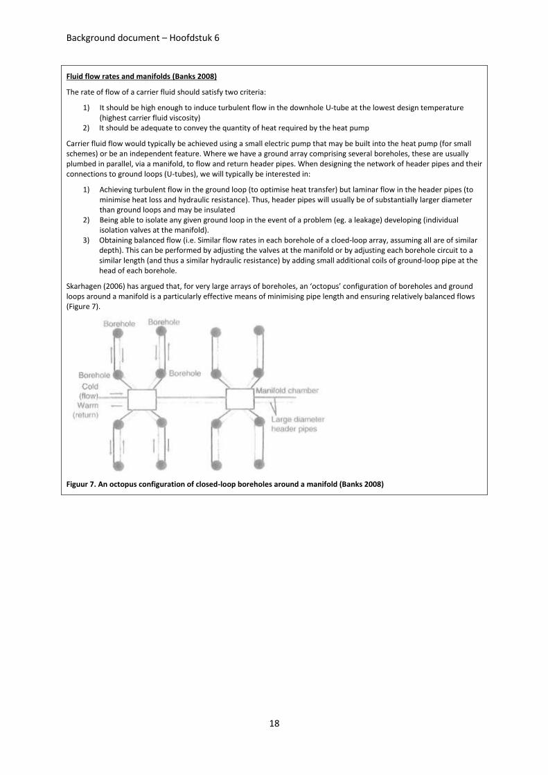
Skarhagen (2006) has argued that, for very large arrays of boreholes, an ‘octopus’ configuration of boreholes and ground loops around a manifold is a particularly effective means of minimising pipe length and ensuring relatively balanced flows (Figure 7).
Figuur 7. An octopus configuration of closed-loop boreholes around a manifold (Banks 2008)
Background document – Hoofdstuk 6
19
6.3. Dimensioneren
6.3.1. Kengetallen en vuistregels voor eerste benadering
ISSO-publicatie 81 (2007)
Voor nieuwbouw woningen:
Warmtevermogen: Ontwerp: 30-60 W/m² Bruto vloeroppervlak (=bvo = vloeroppervlak op basis van de buitenafmetingen van een gebouw. Het gebruiksoppervlak (Ag) in de energieprestatienormen (EPN) is normaliter ca. 90% van de bvo (ISSO-publicatie 81, 2007)
Warmtebehoefte: o Netto (inclusief interne/externe warmtelast en warmtapwater): ca. 1800 vollasturen per jaar. o Netto (inclusief interne/externe warmtelast, exclusief warmtapwater): ca. 1200 vollasturen per jaar.
Voor nieuwbouw kantoren:
Warmtevermogen: Ontwerp (exclusief opwarmtoeslag): 25-60 W/m² bvo. Netto (inclusief interne/externe warmtelast): 15-30 W/m² bvo.
Warmtebehoefte: netto (incl. int/ext warmtelast): 20-40 kWh/m² bvo per jaar.
Indien verder onderbouwde gegevens bekend zijn uit het programma van eisen en het bouwkundig ontwerp, dient daarvan gebruik gemaakt te worden. Voor vertaling naar de warmtevraag aan het bodemsysteem dienen deze waarden met 0,75 te worden vermenigvuldigd (vanwege de werking van de warmtepomp; bij een COP van 4,0).
Globale uitgangspunten:
Specifiek maximum piekvermogen van de bodemwarmtewisselaar: 20 W/m tot 50 W/m;
Gewenste of beschikbare diepte: 20 m tot 150 m; o praktische dieptes voor boren 50 tot 150 m; o praktische dieptes voor drukken 20 tot 50 m.
Onderlinge afstand van de bodemwarmtewisselaars: 4 m tot 8 m, vertaald naar vereist bodemoppervlak per bodemwarmtewisselaar: 16 m² tot 64 m².
Bereken het benodigd grondoppervlak en controleer of het beschikbaar grondoppervlak voldoende is.
Banks (2008)
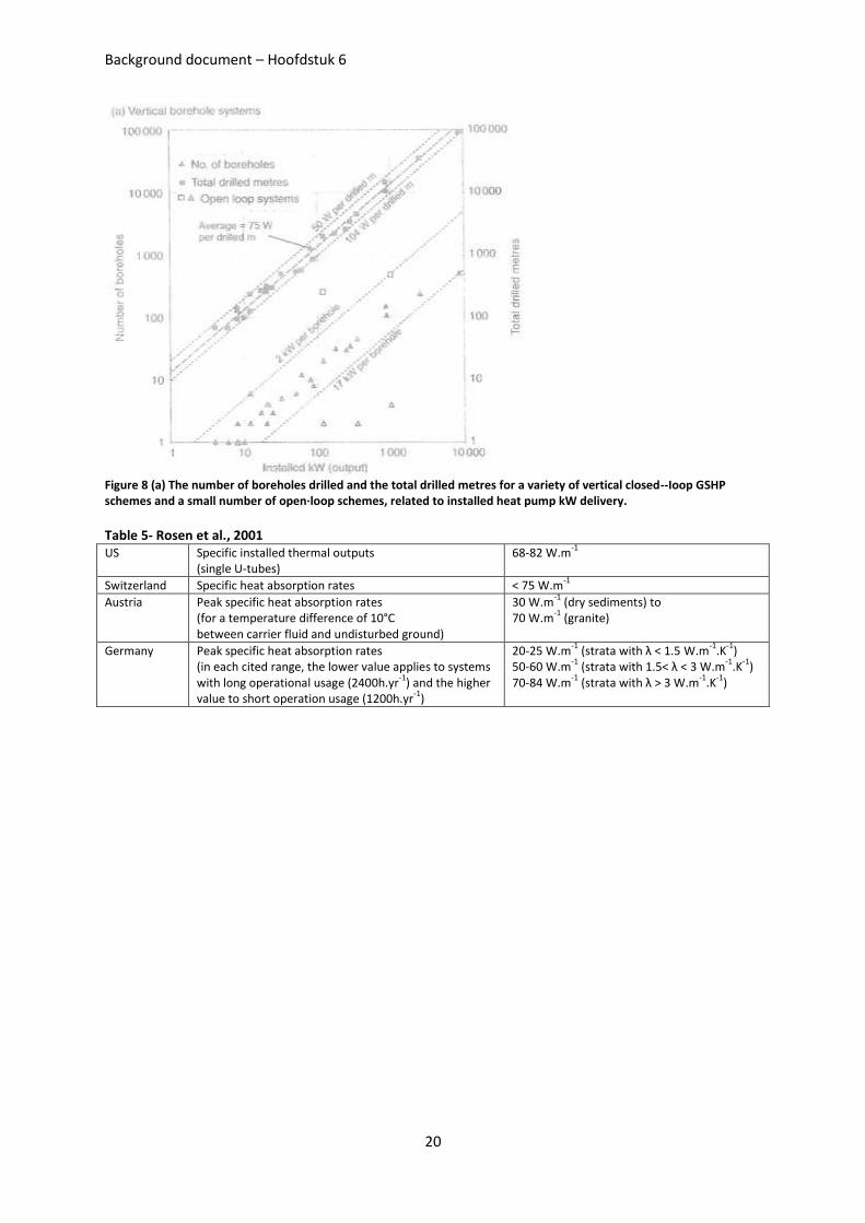
Figure 8 demonstrates that there is a relationship between the number of closed-loop boreholes per scheme and the installed heat pump capacity in kW. The smallest installed capacities are related to the shallowest boreholes (40m) and the highest to the deepest boreholes (180m). If we divide the installed heat pump capacity of the scheme by the total number of drilled borehole metres, we obtain a much more linear relationship, with specific installed thermal outputs of between 50 and 104kW per drilled metre (average 75kW per drilled metre). If we assume that a heat pump scheme has a typical COP=3.4, then these figures equate to specific heat absorption rates (from the ground) of 35-73 W.m
-1 (average
53 W.m-1
). There will come a cut-off point where it becomes cheaper to commence a new borehole than to continue drilling ever deeper in a single borehole (at around 100m). Across Europe in general, the average peak specific heat absorption rate is estimated at 62 W.m
-1, (and taken over the entire heating season, 159 kWh m
-1yr
-1) for systems with
operating times of 1600-2400 hr.yr-1
(Rosen et al, 2001). The performance of a closed-loop system will also depend on:
- The thermal conductivity, specific heat capacity and temperature of the ground - The operational pattern of the scheme (number of equivalent full-load operational hours per heating season
duration of peak operation on a daily basis) - The operating temperature of the ground loop
The rule of thumb are derived from consideration of relatively small, heating only (or heating dominated) schemes in temperate and northern Europe. With large projects, cooling requirements become more dominant. Furthermore, in sizable schemes the number of boreholes begins to be large compared with available land area. In these circumstances, thermal interference between closely spaced boreholes and complex heating and cooling loads also begin to come into play. For large ground source heating and cooling projects, we require a more sophisticated understanding of subsurface heat storage and transfer, site-specific input data and more nuanced design tools than mere ‘rules of thumb’. We should be wary of ‘rules of thumb’ relating drilled metres to thermal output. First, ground thermal properties will have some influence. Second, heat transfer rates per metre of borehole will depend on our design loop operating temperature. A warmer loop (in heating mode) means less conductive heat transfer from the ground (but probably a higher heat pump COPH). Third, patterns of heat usage will be important. A greater number of borehole metres will be necessary to support a 12kW heat pump with 3200 operational hours per year than one with 500 hours. Fourth, we should be aware that in large, complex buildings, the total installed heat pump capacity may not be identical to peak heating load: it may be greater, because the building may be divided into different zones, whose peak heating demands occur at different times of day (Kavanaugh and Rafferty, 1997). In summary, ‘rules of thumb’ are a good starting point of design, especially for smaller, simple systems, but system design involves more complex considerations.
Background document – Hoofdstuk 6
20
Figure 8 (a) The number of boreholes drilled and the total drilled metres for a variety of vertical closed--Ioop GSHP schemes and a small number of open·loop schemes, related to installed heat pump kW delivery.
Table 5- Rosen et al., 2001 US Specific installed thermal outputs
(single U-tubes) 68-82 W.m
-1
Switzerland Specific heat absorption rates < 75 W.m-1
Austria Peak specific heat absorption rates (for a temperature difference of 10°C between carrier fluid and undisturbed ground)
30 W.m-1
(dry sediments) to 70 W.m
-1 (granite)
Germany Peak specific heat absorption rates (in each cited range, the lower value applies to systems with long operational usage (2400h.yr
-1) and the higher
value to short operation usage (1200h.yr-1
)
20-25 W.m-1
(strata with λ < 1.5 W.m-1
.K-1
) 50-60 W.m
-1 (strata with 1.5< λ < 3 W.m
-1.K
-1)
70-84 W.m-1
(strata with λ > 3 W.m-1
.K-1
)
Background document – Hoofdstuk 6
21
6.3.2. Berekeningen volgens IGHSPA 2009
The steps in designing the vertically-bored, closed-loop GHEX include:
1. Define the design heating or cooling load and select GSHP equipment 2. Lay out the GHEX by selecting pipe sizes for the ground loops that meet turbulence and head loss
constraints and using a header arrangement that balances flow between the ground loops and facilitates flushing and purging of the GHEX.
3. Estimate the design heating or cooling month run fraction and the annual heating and cooling ground loads using a bin analysis or graphed data.
4. Determine the deep-earth temperature where the vertically-bored GHEX will be installed. 5. Estimate the thermal properties (thermal conductivity and diffusivity) of the ground formation into
which the vertically-bored GHEX will be installed. 6. Select borehole completion information (borehole diameter, U-bend pipe size, and grout thermal
conductivity) that will be used in the installation. 7. Determine the ground loop resistance from tabled data for the selected U-bend pipe size accounting
for design month run fraction, ground formation thermal conductivity, borehole diameter, and grout thermal conductivity.
8. Calculate the total design heating or cooling borehole length and divide by the number of boreholes to determine the active borehole length.
9. Adjust the heating or cooling design lengths to account for unbalanced ground loads, if necessary. 10. Revise the design, as necessary, to meet potential space limitations on the installation site by
balancing the number and spacing of boreholes against drilling depths that can be achieved economically.
Ground loop resistance tables are provided in IGSHPA (2009), which combine the effects of ground thermal properties, pipe diameter, borehole diameter, grout thermal conductivity, and run fraction of the heat pump during the design month. The effects of unbalanced ground loads in heating and cooling are addressed utilizing a bore length multiplier ( ) to account for long-term cooling or warming of the ground near the vertically-bored ground loops. Vertically-bored GHEX design worksheets for both heating and cooling mode are provided in IGSHPA (2009) to facilitate the design process and provide documentation of the design for easy record keeping. The design heating or cooling borehole lengths that result directly from the equations and data presented below are for residential and light commercial GSHP applications with a relatively small number of ground loops spaced such that they minimally interfere with each other. If the heating and cooling ground loads are relatively unbalanced, then borehole length multipliers are provided for one, two, or three-row bore fields that account for borehole spacing and adjust borehole lengths for long-term energy depletion or build up in the soil or rock in and around the vertical ground loop field. For GSHP applications that require a large number of boreholes in a grid arrangement, and have heating and cooling ground loads that are extremely unbalanced, it is highly recommended that the designs lengths be checked against commercial ground loop design software tools (GCHPCalc, GLHEPRO, GLD, etc.) that are designed to account for unbalanced ground loads and the influence of borehole spacing.
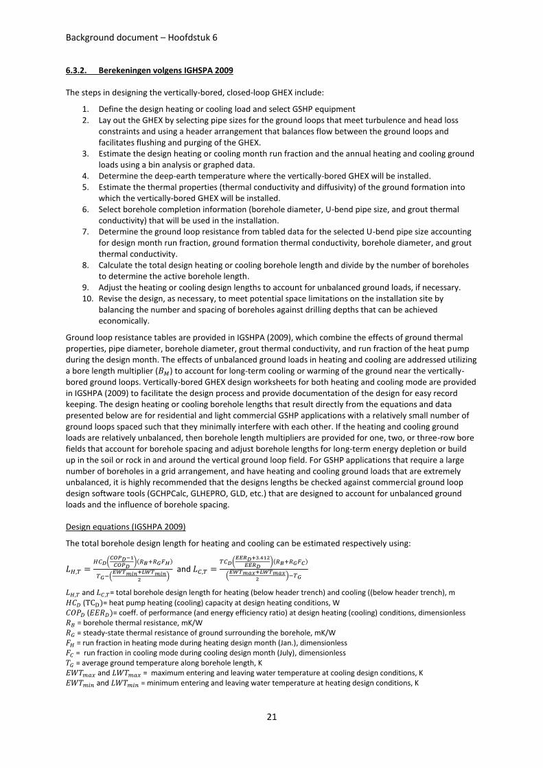
Design equations (IGSHPA 2009)
The total borehole design length for heating and cooling can be estimated respectively using:
(
)( )
(
)
and (
)( )
(
)
and = total borehole design length for heating (below header trench) and cooling ((below header trench), m
( )= heat pump heating (cooling) capacity at design heating conditions, W ( )= coeff. of performance (and energy efficiency ratio) at design heating (cooling) conditions, dimensionless = borehole thermal resistance, mK/W = steady-state thermal resistance of ground surrounding the borehole, mK/W = run fraction in heating mode during heating design month (Jan.), dimensionless = run fraction in cooling mode during cooling design month (July), dimensionless = average ground temperature along borehole length, K and = maximum entering and leaving water temperature at cooling design conditions, K and = minimum entering and leaving water temperature at heating design conditions, K
Background document – Hoofdstuk 6
22
The various parameters in this equation include the heat of extraction (rejection) rate from the ground, which is based on the heating (cooling) capacity and the coefficient of performance (energy efficiency ratio) of the heat pump system at design heating (cooling) conditions, including corrections for operating conditions. The design minimum (maximum) entering and leaving water temperatures are also determined as part of the heat pump selection. Run fraction in heating mode during the heating design month (Jan) is combined with hot water generation run fraction if utilized, for a design month run fraction in heating (conservative approach). The individual borehole design length for heating and cooling can be calculated using:
and
Where is the number of boreholes connected to the heat pump system
Deep earth temperature
The deep-earth temperature is the average temperature of the soil or rock into which the vertical ground heat exchanger will be installed and is generally constant at depths ranging from 6 to 60 meters. Between the surface and about a 6m depth the temperature of the soil varies with location, depth, type of soil, and time of year. This variation has little influence on the design of a vertically-bored GHEX because a very small percentage of the active borehole length is in the approximately 4-5m of ground between the 6m depth and the bottom of the header trench, which is usually 1.2 à 1.8m. At depths greater than 60m, the earth temperature begins to increase at a rate that depends on location and the degree of heat flow toward the surface from high temperature geothermal sources deep below the surface.
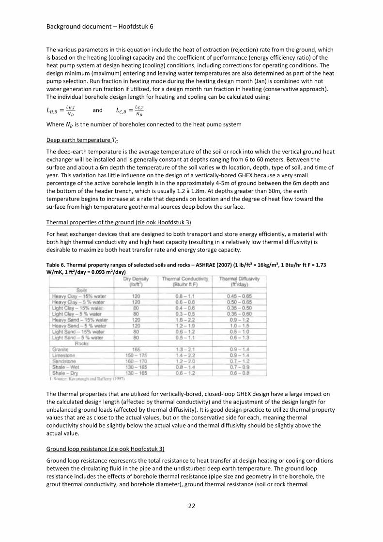
Thermal properties of the ground (zie ook Hoofdstuk 3)
For heat exchanger devices that are designed to both transport and store energy efficiently, a material with both high thermal conductivity and high heat capacity (resulting in a relatively low thermal diffusivity) is desirable to maximize both heat transfer rate and energy storage capacity.
Table 6. Thermal property ranges of selected soils and rocks – ASHRAE (2007) (1 lb/ft³ = 16kg/m³, 1 Btu/hr ft F = 1.73 W/mK, 1 ft²/day = 0.093 m²/day)
The thermal properties that are utilized for vertically-bored, closed-loop GHEX design have a large impact on the calculated design length (affected by thermal conductivity) and the adjustment of the design length for unbalanced ground loads (affected by thermal diffusivity). It is good design practice to utilize thermal property values that are as close to the actual values, but on the conservative side for each, meaning thermal conductivity should be slightly below the actual value and thermal diffusivity should be slightly above the actual value.
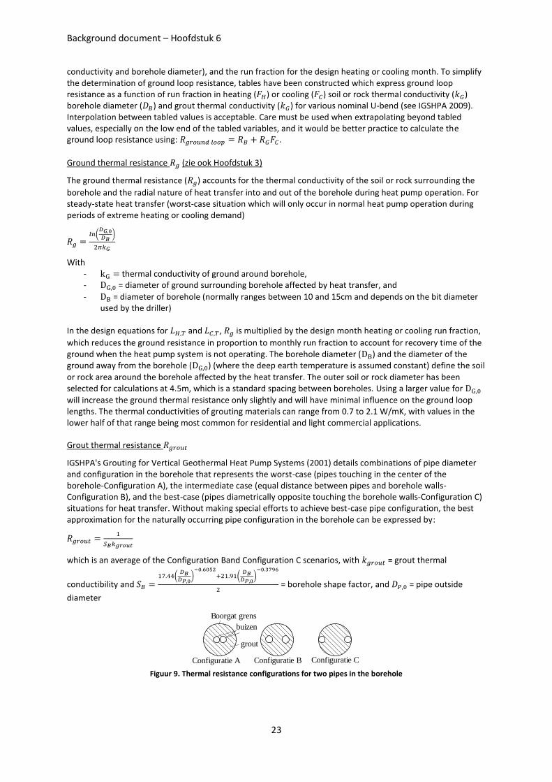
Ground loop resistance (zie ook Hoofdstuk 3)
Ground loop resistance represents the total resistance to heat transfer at design heating or cooling conditions between the circulating fluid in the pipe and the undisturbed deep earth temperature. The ground loop resistance includes the effects of borehole thermal resistance (pipe size and geometry in the borehole, the grout thermal conductivity, and borehole diameter), ground thermal resistance (soil or rock thermal
Background document – Hoofdstuk 6
23
conductivity and borehole diameter), and the run fraction for the design heating or cooling month. To simplify the determination of ground loop resistance, tables have been constructed which express ground loop resistance as a function of run fraction in heating ( ) or cooling ( ) soil or rock thermal conductivity ( ) borehole diameter ( ) and grout thermal conductivity ( ) for various nominal U-bend (see IGSHPA 2009). Interpolation between tabled values is acceptable. Care must be used when extrapolating beyond tabled values, especially on the low end of the tabled variables, and it would be better practice to calculate the ground loop resistance using: .
Ground thermal resistance (zie ook Hoofdstuk 3)
The ground thermal resistance ( ) accounts for the thermal conductivity of the soil or rock surrounding the
borehole and the radial nature of heat transfer into and out of the borehole during heat pump operation. For steady-state heat transfer (worst-case situation which will only occur in normal heat pump operation during periods of extreme heating or cooling demand)
(
)
With - thermal conductivity of ground around borehole, - = diameter of ground surrounding borehole affected by heat transfer, and
- = diameter of borehole (normally ranges between 10 and 15cm and depends on the bit diameter used by the driller)
In the design equations for and , is multiplied by the design month heating or cooling run fraction,
which reduces the ground resistance in proportion to monthly run fraction to account for recovery time of the ground when the heat pump system is not operating. The borehole diameter ( ) and the diameter of the ground away from the borehole ( ) (where the deep earth temperature is assumed constant) define the soil
or rock area around the borehole affected by the heat transfer. The outer soil or rock diameter has been selected for calculations at 4.5m, which is a standard spacing between boreholes. Using a larger value for
will increase the ground thermal resistance only slightly and will have minimal influence on the ground loop lengths. The thermal conductivities of grouting materials can range from 0.7 to 2.1 W/mK, with values in the lower half of that range being most common for residential and light commercial applications.
Grout thermal resistance
IGSHPA's Grouting for Vertical Geothermal Heat Pump Systems (2001) details combinations of pipe diameter and configuration in the borehole that represents the worst-case (pipes touching in the center of the borehole-Configuration A), the intermediate case (equal distance between pipes and borehole walls-Configuration B), and the best-case (pipes diametrically opposite touching the borehole walls-Configuration C) situations for heat transfer. Without making special efforts to achieve best-case pipe configuration, the best approximation for the naturally occurring pipe configuration in the borehole can be expressed by:
which is an average of the Configuration Band Configuration C scenarios, with = grout thermal
conductibility and (
)
(
)
= borehole shape factor, and = pipe outside
diameter
Figuur 9. Thermal resistance configurations for two pipes in the borehole
Configuratie A Configuratie B Configuratie C
buizen
Boorgat grens
grout
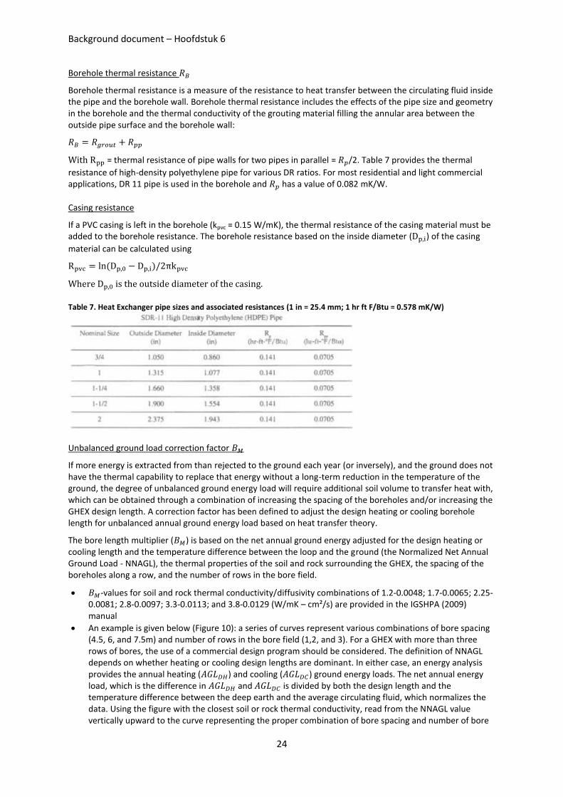
Background document – Hoofdstuk 6
24
Borehole thermal resistance
Borehole thermal resistance is a measure of the resistance to heat transfer between the circulating fluid inside the pipe and the borehole wall. Borehole thermal resistance includes the effects of the pipe size and geometry in the borehole and the thermal conductivity of the grouting material filling the annular area between the outside pipe surface and the borehole wall:
With = thermal resistance of pipe walls for two pipes in parallel = /2. Table 7 provides the thermal
resistance of high-density polyethylene pipe for various DR ratios. For most residential and light commercial applications, DR 11 pipe is used in the borehole and has a value of 0.082 mK/W.
Casing resistance
If a PVC casing is left in the borehole (kpvc = 0.15 W/mK), the thermal resistance of the casing material must be added to the borehole resistance. The borehole resistance based on the inside diameter ( ) of the casing
material can be calculated using
( )
Where is the outside diameter of the casing.
Table 7. Heat Exchanger pipe sizes and associated resistances (1 in = 25.4 mm; 1 hr ft F/Btu = 0.578 mK/W)
Unbalanced ground load correction factor
If more energy is extracted from than rejected to the ground each year (or inversely), and the ground does not have the thermal capability to replace that energy without a long-term reduction in the temperature of the ground, the degree of unbalanced ground energy load will require additional soil volume to transfer heat with, which can be obtained through a combination of increasing the spacing of the boreholes and/or increasing the GHEX design length. A correction factor has been defined to adjust the design heating or cooling borehole length for unbalanced annual ground energy load based on heat transfer theory.
The bore length multiplier ( ) is based on the net annual ground energy adjusted for the design heating or cooling length and the temperature difference between the loop and the ground (the Normalized Net Annual Ground Load - NNAGL), the thermal properties of the soil and rock surrounding the GHEX, the spacing of the boreholes along a row, and the number of rows in the bore field.
-values for soil and rock thermal conductivity/diffusivity combinations of 1.2-0.0048; 1.7-0.0065; 2.25-0.0081; 2.8-0.0097; 3.3-0.0113; and 3.8-0.0129 (W/mK – cm²/s) are provided in the IGSHPA (2009) manual
An example is given below (Figure 10): a series of curves represent various combinations of bore spacing (4.5, 6, and 7.5m) and number of rows in the bore field (1,2, and 3). For a GHEX with more than three rows of bores, the use of a commercial design program should be considered. The definition of NNAGL depends on whether heating or cooling design lengths are dominant. In either case, an energy analysis provides the annual heating ( ) and cooling ( ) ground energy loads. The net annual energy load, which is the difference in and is divided by both the design length and the temperature difference between the deep earth and the average circulating fluid, which normalizes the data. Using the figure with the closest soil or rock thermal conductivity, read from the NNAGL value vertically upward to the curve representing the proper combination of bore spacing and number of bore
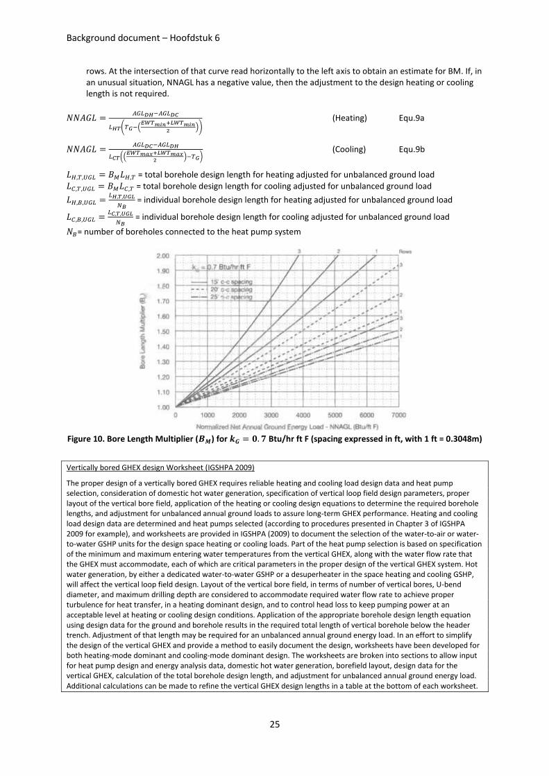
Background document – Hoofdstuk 6
25
rows. At the intersection of that curve read horizontally to the left axis to obtain an estimate for BM. If, in an unusual situation, NNAGL has a negative value, then the adjustment to the design heating or cooling length is not required.
( (
))
(Heating) Equ.9a
((
) )
(Cooling) Equ.9b
= total borehole design length for heating adjusted for unbalanced ground load
= total borehole design length for cooling adjusted for unbalanced ground load
= individual borehole design length for heating adjusted for unbalanced ground load
= individual borehole design length for cooling adjusted for unbalanced ground load
= number of boreholes connected to the heat pump system
Figure 10. Bore Length Multiplier ( ) for Btu/hr ft F (spacing expressed in ft, with 1 ft = 0.3048m)
Vertically bored GHEX design Worksheet (IGSHPA 2009)
The proper design of a vertically bored GHEX requires reliable heating and cooling load design data and heat pump selection, consideration of domestic hot water generation, specification of vertical loop field design parameters, proper layout of the vertical bore field, application of the heating or cooling design equations to determine the required borehole lengths, and adjustment for unbalanced annual ground loads to assure long-term GHEX performance. Heating and cooling load design data are determined and heat pumps selected (according to procedures presented in Chapter 3 of IGSHPA 2009 for example), and worksheets are provided in IGSHPA (2009) to document the selection of the water-to-air or water-to-water GSHP units for the design space heating or cooling loads. Part of the heat pump selection is based on specification of the minimum and maximum entering water temperatures from the vertical GHEX, along with the water flow rate that the GHEX must accommodate, each of which are critical parameters in the proper design of the vertical GHEX system. Hot water generation, by either a dedicated water-to-water GSHP or a desuperheater in the space heating and cooling GSHP, will affect the vertical loop field design. Layout of the vertical bore field, in terms of number of vertical bores, U-bend diameter, and maximum drilling depth are considered to accommodate required water flow rate to achieve proper turbulence for heat transfer, in a heating dominant design, and to control head loss to keep pumping power at an acceptable level at heating or cooling design conditions. Application of the appropriate borehole design length equation using design data for the ground and borehole results in the required total length of vertical borehole below the header trench. Adjustment of that length may be required for an unbalanced annual ground energy load. In an effort to simplify the design of the vertical GHEX and provide a method to easily document the design, worksheets have been developed for both heating-mode dominant and cooling-mode dominant design. The worksheets are broken into sections to allow input for heat pump design and energy analysis data, domestic hot water generation, borefield layout, design data for the vertical GHEX, calculation of the total borehole design length, and adjustment for unbalanced annual ground energy load. Additional calculations can be made to refine the vertical GHEX design lengths in a table at the bottom of each worksheet.
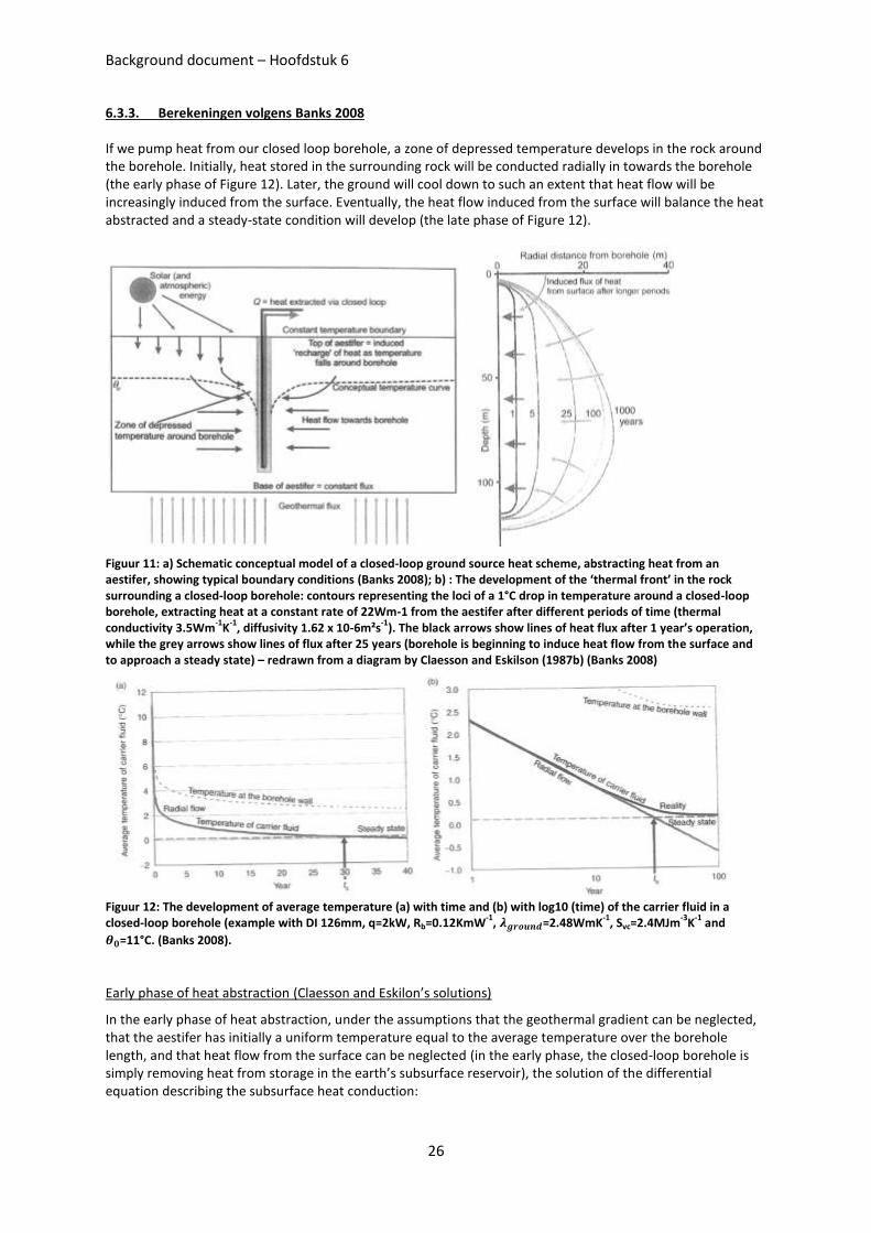
Background document – Hoofdstuk 6
26
6.3.3. Berekeningen volgens Banks 2008
If we pump heat from our closed loop borehole, a zone of depressed temperature develops in the rock around the borehole. Initially, heat stored in the surrounding rock will be conducted radially in towards the borehole (the early phase of Figure 12). Later, the ground will cool down to such an extent that heat flow will be increasingly induced from the surface. Eventually, the heat flow induced from the surface will balance the heat abstracted and a steady-state condition will develop (the late phase of Figure 12).
Figuur 11: a) Schematic conceptual model of a closed-loop ground source heat scheme, abstracting heat from an aestifer, showing typical boundary conditions (Banks 2008); b) : The development of the ‘thermal front’ in the rock surrounding a closed-loop borehole: contours representing the loci of a 1°C drop in temperature around a closed-loop borehole, extracting heat at a constant rate of 22Wm-1 from the aestifer after different periods of time (thermal conductivity 3.5Wm
-1K
-1, diffusivity 1.62 x 10⁻⁶m²s
-1). The black arrows show lines of heat flux after 1 year’s operation,
while the grey arrows show lines of flux after 25 years (borehole is beginning to induce heat flow from the surface and to approach a steady state) – redrawn from a diagram by Claesson and Eskilson (1987b) (Banks 2008)
Figuur 12: The development of average temperature (a) with time and (b) with log10 (time) of the carrier fluid in a closed-loop borehole (example with DI 126mm, q=2kW, Rb=0.12KmW
-1, =2.48WmK
-1, Svc=2.4MJm
-3K
-1 and
=11°C. (Banks 2008).
Early phase of heat abstraction (Claesson and Eskilon’s solutions)
In the early phase of heat abstraction, under the assumptions that the geothermal gradient can be neglected, that the aestifer has initially a uniform temperature equal to the average temperature over the borehole length, and that heat flow from the surface can be neglected (in the early phase, the closed-loop borehole is simply removing heat from storage in the earth’s subsurface reservoir), the solution of the differential equation describing the subsurface heat conduction:
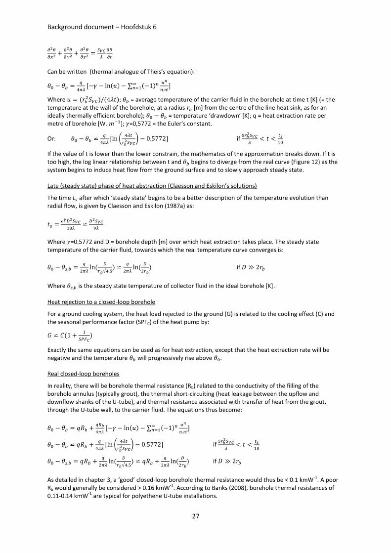
Background document – Hoofdstuk 6
27
Can be written (thermal analogue of Theis’s equation):
( )
( )
Where ( ) ( ); = average temperature of the carrier fluid in the borehole at time t [K] (= the
temperature at the wall of the borehole, at a radius [m] from the centre of the line heat sink, as for an ideally thermally efficient borehole); = temperature ‘drawdown’ [K]; q = heat extraction rate per metre of borehole [W. ]; =0,5772 = the Euler’s constant.
Or:
(
) if
If the value of t is lower than the lower constrain, the mathematics of the approximation breaks down. If t is too high, the log linear relationship between t and begins to diverge from the real curve (Figure 12) as the system begins to induce heat flow from the ground surface and to slowly approach steady state.
Late (steady state) phase of heat abstraction (Claesson and Eskilon’s solutions)
The time after which ‘steady state’ begins to be a better description of the temperature evolution than radial flow, is given by Claesson and Eskilon (1987a) as:
Where =0.5772 and D = borehole depth [m] over which heat extraction takes place. The steady state temperature of the carrier fluid, towards which the real temperature curve converges is:
(
)
(
) if
Where is the steady state temperature of collector fluid in the ideal borehole [K].
Heat rejection to a closed-loop borehole
For a ground cooling system, the heat load rejected to the ground (G) is related to the cooling effect (C) and the seasonal performance factor (SPFC) of the heat pump by:
(
)
Exactly the same equations can be used as for heat extraction, except that the heat extraction rate will be negative and the temperature will progressively rise above .
Real closed-loop boreholes
In reality, there will be borehole thermal resistance (Rb) related to the conductivity of the filling of the borehole annulus (typically grout), the thermal short-circuiting (heat leakage between the upflow and downflow shanks of the U-tube), and thermal resistance associated with transfer of heat from the grout, through the U-tube wall, to the carrier fluid. The equations thus become:
( )
( )
(
) if
(
)
(
) if
As detailed in chapter 3, a ‘good’ closed-loop borehole thermal resistance would thus be < 0.1 kmW-1
. A poor Rb would generally be considered > 0.16 kmW
-1. According to Banks (2008), borehole thermal resistances of
0.11-0.14 kmW-1
are typical for polyethene U-tube installations.
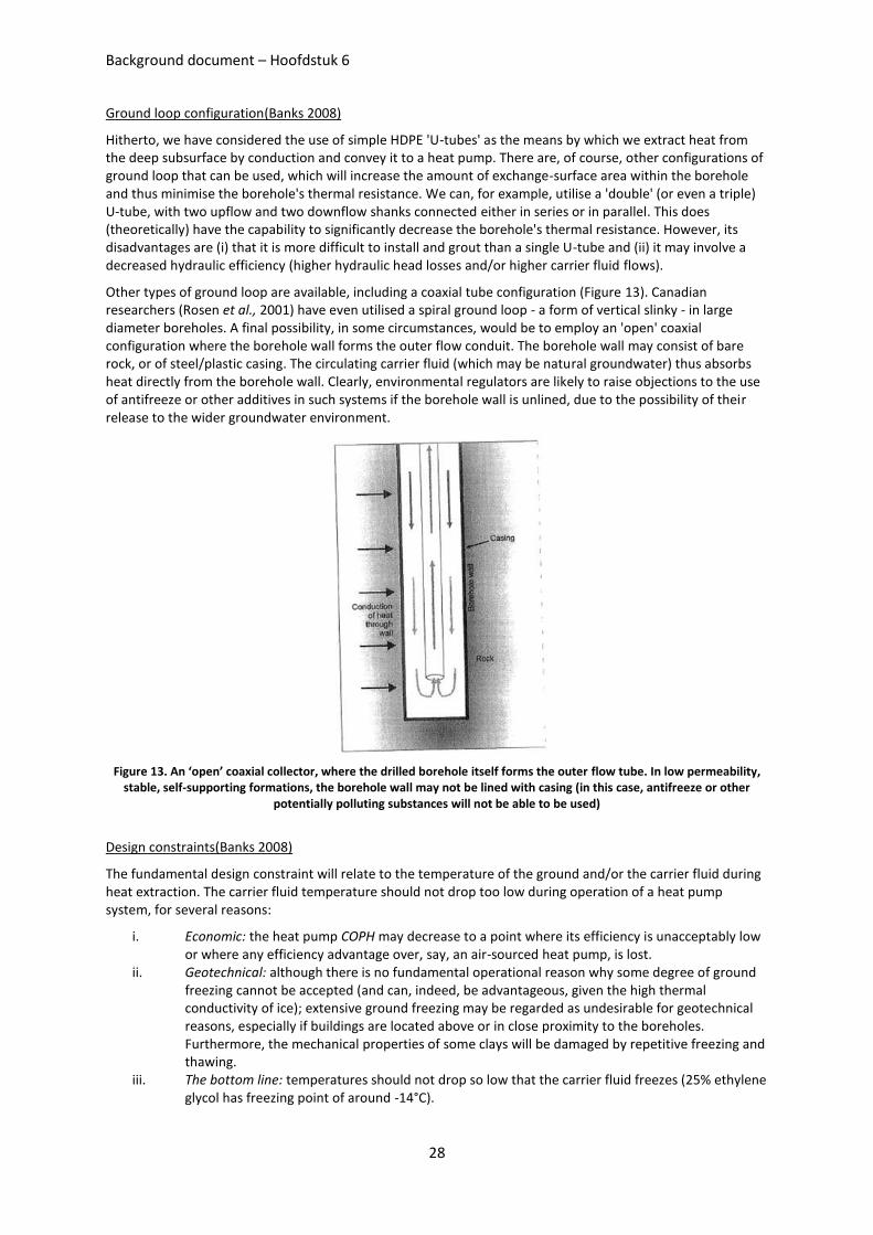
Background document – Hoofdstuk 6
28
Ground loop configuration(Banks 2008)
Hitherto, we have considered the use of simple HDPE 'U-tubes' as the means by which we extract heat from the deep subsurface by conduction and convey it to a heat pump. There are, of course, other configurations of ground loop that can be used, which will increase the amount of exchange-surface area within the borehole and thus minimise the borehole's thermal resistance. We can, for example, utilise a 'double' (or even a triple) U-tube, with two upflow and two downflow shanks connected either in series or in parallel. This does (theoretically) have the capability to significantly decrease the borehole's thermal resistance. However, its disadvantages are (i) that it is more difficult to install and grout than a single U-tube and (ii) it may involve a decreased hydraulic efficiency (higher hydraulic head losses and/or higher carrier fluid flows).
Other types of ground loop are available, including a coaxial tube configuration (Figure 13). Canadian researchers (Rosen et al., 2001) have even utilised a spiral ground loop - a form of vertical slinky - in large diameter boreholes. A final possibility, in some circumstances, would be to employ an 'open' coaxial configuration where the borehole wall forms the outer flow conduit. The borehole wall may consist of bare rock, or of steel/plastic casing. The circulating carrier fluid (which may be natural groundwater) thus absorbs heat directly from the borehole wall. Clearly, environmental regulators are likely to raise objections to the use of antifreeze or other additives in such systems if the borehole wall is unlined, due to the possibility of their release to the wider groundwater environment.
Figure 13. An ‘open’ coaxial collector, where the drilled borehole itself forms the outer flow tube. In low permeability, stable, self-supporting formations, the borehole wall may not be lined with casing (in this case, antifreeze or other
potentially polluting substances will not be able to be used)
Design constraints(Banks 2008)
The fundamental design constraint will relate to the temperature of the ground and/or the carrier fluid during heat extraction. The carrier fluid temperature should not drop too low during operation of a heat pump system, for several reasons:
i. Economic: the heat pump COPH may decrease to a point where its efficiency is unacceptably low or where any efficiency advantage over, say, an air-sourced heat pump, is lost.
ii. Geotechnical: although there is no fundamental operational reason why some degree of ground freezing cannot be accepted (and can, indeed, be advantageous, given the high thermal conductivity of ice); extensive ground freezing may be regarded as undesirable for geotechnical reasons, especially if buildings are located above or in close proximity to the boreholes. Furthermore, the mechanical properties of some clays will be damaged by repetitive freezing and thawing.
iii. The bottom line: temperatures should not drop so low that the carrier fluid freezes (25% ethylene glycol has freezing point of around -14°C).
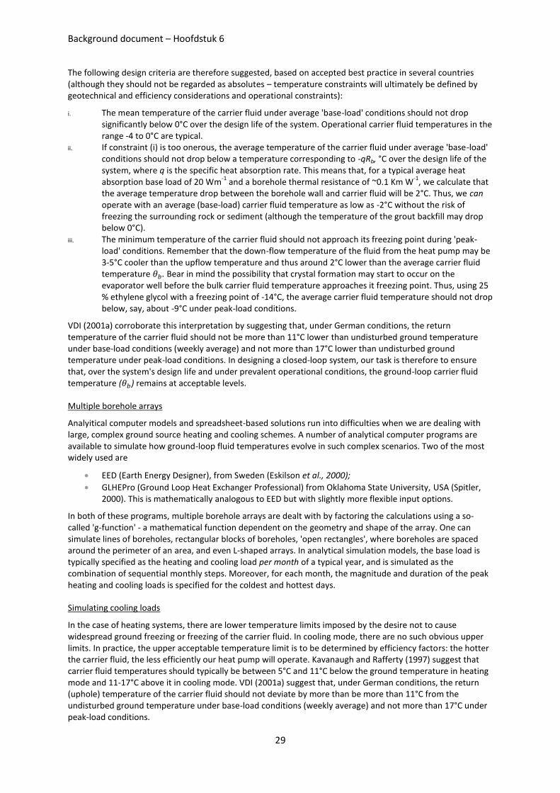
Background document – Hoofdstuk 6
29
The following design criteria are therefore suggested, based on accepted best practice in several countries (although they should not be regarded as absolutes – temperature constraints will ultimately be defined by geotechnical and efficiency considerations and operational constraints):
i. The mean temperature of the carrier fluid under average 'base-load' conditions should not drop significantly below 0°C over the design life of the system. Operational carrier fluid temperatures in the range -4 to 0°C are typical.
ii. If constraint (i) is too onerous, the average temperature of the carrier fluid under average 'base-load' conditions should not drop below a temperature corresponding to -qRb, °C over the design life of the system, where q is the specific heat absorption rate. This means that, for a typical average heat absorption base load of 20 Wm
-1 and a borehole thermal resistance of ~0.1 Km W
-1, we calculate that
the average temperature drop between the borehole wall and carrier fluid will be 2°C. Thus, we can operate with an average (base-load) carrier fluid temperature as low as -2°C without the risk of freezing the surrounding rock or sediment (although the temperature of the grout backfill may drop below 0°C).
iii. The minimum temperature of the carrier fluid should not approach its freezing point during 'peak-load' conditions. Remember that the down-flow temperature of the fluid from the heat pump may be 3-5°C cooler than the upflow temperature and thus around 2°C lower than the average carrier fluid temperature . Bear in mind the possibility that crystal formation may start to occur on the evaporator well before the bulk carrier fluid temperature approaches it freezing point. Thus, using 25 % ethylene glycol with a freezing point of -14°C, the average carrier fluid temperature should not drop below, say, about -9°C under peak-load conditions.
VDI (2001a) corroborate this interpretation by suggesting that, under German conditions, the return temperature of the carrier fluid should not be more than 11°C lower than undisturbed ground temperature under base-load conditions (weekly average) and not more than 17°C lower than undisturbed ground temperature under peak-load conditions. In designing a closed-loop system, our task is therefore to ensure that, over the system's design life and under prevalent operational conditions, the ground-loop carrier fluid temperature ( ) remains at acceptable levels.
Multiple borehole arrays
Analyitical computer models and spreadsheet-based solutions run into difficulties when we are dealing with large, complex ground source heating and cooling schemes. A number of analytical computer programs are available to simulate how ground-loop fluid temperatures evolve in such complex scenarios. Two of the most widely used are
EED (Earth Energy Designer), from Sweden (Eskilson et al., 2000);
GLHEPro (Ground Loop Heat Exchanger Professional) from Oklahoma State University, USA (Spitler, 2000). This is mathematically analogous to EED but with slightly more flexible input options.
In both of these programs, multiple borehole arrays are dealt with by factoring the calculations using a so-called 'g-function' - a mathematical function dependent on the geometry and shape of the array. One can simulate lines of boreholes, rectangular blocks of boreholes, 'open rectangles', where boreholes are spaced around the perimeter of an area, and even L-shaped arrays. In analytical simulation models, the base load is typically specified as the heating and cooling load per month of a typical year, and is simulated as the combination of sequential monthly steps. Moreover, for each month, the magnitude and duration of the peak heating and cooling loads is specified for the coldest and hottest days.
Simulating cooling loads
In the case of heating systems, there are lower temperature limits imposed by the desire not to cause widespread ground freezing or freezing of the carrier fluid. In cooling mode, there are no such obvious upper limits. In practice, the upper acceptable temperature limit is to be determined by efficiency factors: the hotter the carrier fluid, the less efficiently our heat pump will operate. Kavanaugh and Rafferty (1997) suggest that carrier fluid temperatures should typically be between 5°C and 11°C below the ground temperature in heating mode and 11-17°C above it in cooling mode. VDI (2001a) suggest that, under German conditions, the return (uphole) temperature of the carrier fluid should not deviate by more than be more than 11°C from the undisturbed ground temperature under base-load conditions (weekly average) and not more than 17°C under peak-load conditions.
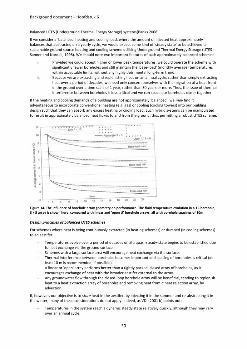
Background document – Hoofdstuk 6
30
Balanced UTES (Underground Thermal Energy Storage) systems(Banks 2008)
If we consider a 'balanced' heating and cooling load, where the amount of injected heat approximately balances that abstracted on a yearly cycle, we would expect some kind of 'steady state' to be achieved: a sustainable ground source heating and cooling scheme utilising Underground Thermal Energy Storage (UTES - Sanner and Nordell, 1998). We should note two important features of such approximately balanced schemes:
i. Provided we could accept higher or lower peak temperatures, we could operate the scheme with significantly fewer boreholes and still maintain the 'base-load' (monthly average) temperatures within acceptable limits, without any highly detrimental long-term trend.
ii. Because we are extracting and replenishing heat on an annual cycle, rather than simply extracting heat over a period of decades, we need only concern ourselves with the migration of a heat front in the ground over a time scale of 1 year, rather than 30 years or more. Thus, the issue of thermal interference between boreholes is less critical and we can space our boreholes closer together.
If the heating and cooling demands of a building are not approximately 'balanced', we may find it advantageous to incorporate conventional heating (e.g. gas) or cooling (cooling towers) into our building design such that they can absorb any excess heating or cooling load. Such hybrid systems can be manipulated to result in approximately balanced heat fluxes to and from the ground, thus permitting a robust UTES scheme.
Figure 14. The influence of borehole array geometry on performance. The fluid temperature evolution in a 15-borehole, 3 x 5 array is shown here, compared with linear and ‘open U’ borehole arrays, all with borehole spacings of 10m
Design principles of balanced UTES schemes
For schemes where heat is being continuously extracted (in heating schemes) or dumped (in cooling schemes) to an aestifer:
- Temperatures evolve over a period of decades until a quasi-steady-state begins to be established due to heat exchange via the ground surface.
- Schemes with a large surface area will encourage heat exchange via the surface. - Thermal interference between boreholes becomes important and spacing of boreholes is critical (at
least 10 m is recommended, if possible). - A linear or 'open' array performs better than a tightly packed, closed array of boreholes, as it
encourages exchange of heat with the broader aestifer external to the array. - Any groundwater flow through the closed-loop borehole array will be beneficial, tending to replenish
heat to a heat extraction array of boreholes and removing heat from a heat rejection array, by advection.
If, however, our objective is to store heat in the aestifer, by injecting it in the summer and re-abstracting it in the winter, many of these considerations do not apply. Indeed, as VDI (2001 b) points out:
- Temperatures in the system reach a dynamic steady state relatively quickly, although they may vary over an annual cycle.
Background document – Hoofdstuk 6
31
- Thermal interference between boreholes is of lesser importance and closer borehole spacings arc possible.
- To avoid leakage of heat outside the array, a more 'closed' array shape will be preferable to an open or linear array. Indeed to minimise the array's overall surface area-to-volume ratio, an equidimensional cylindrical or hexagonal array may be preferable (Figure 14).
- If we wish to minimise heat loss from our subsurface heat store, large throughflows of groundwater will be disadvantageous. Thus, either the hydraulic conductivity should be low to modest or there should be a low groundwater hydraulic gradient in the area.
- More extreme peak temperatures may be possible or even desirable.
Figure 14 compares a linear 'open' array suited to continuous heat extraction, with a more 'closed', hexagonal array, suited to heat storage. The total thermal storage (H) of a cylindrical array of boreholes of depth D and effective array radius rarray is given by:
where Svc = volumetric heat capacity of the aestifer material and is the average change in ground temperature of the ground enclosed by the borehole thermal array. This thermal storage is the amount of heat rejected to the ground in summer and abstracted in winter.
Waste heat from space-cooling heat pumps need not be our only source of surplus heat in summer. If we have a high heating demand in winter that must be satisfied} it becomes increasingly attractive (VDI 2001b) to indulge in supplementary recharge of heat, via the ground loop, to the subsurface by:
installing solar thermal panels to collect summer heat (Gabrielsson, 1997; Sanner and Hellstrom, 1998; Nordell and Hellstrom, 2000);
harvesting surplus summer heat from engines or combined heat-and-power installations;
collecting heat from loops installed under black surfaces, such as roads or car parks.
Common design flaws
- Using simplistic rules of thumb for large systems - Placing boreholes too close together such that thermal interference becomes significant (According to
Banks 2008, a minimum spacing of 10m should be used as a starting point for design of schemes with a highly dominant heating or cooling load; for balanced reversible systems, smaller spacing will be acceptable)
- Lack of appreciation that GSHP cooling systems may require greater borehole lengths to deliver a given cooling load, than heating systems do to provide the same heating load
- Using too short a design life for simulation of the performance of a closed-loop borehole array (the system may not begin to approach a steady state until after some 30 years or more have elapsed)
Background document – Hoofdstuk 6
32
6.4. Case histories
6.4.1. DFS (Hessen, Germany) [Guillame & Donnet 2010]
– 57.000 m² of building offices – Global consumption target: 100 kWh/m²/year – Site located next to protected groundwater well, use is forbidden
Operation:
– Closed loops (no use of groundwater) – Pure water within the pipes (frozen if < 4 degrees at the evaporator of the HP) – Pheating = 330 kW, Pclim = 340 kW
154 drills of 70 m depth, spaced by 5 m each
COP value: 6 (water at 30 degrees)
Emission through ceiling
– HP linked to urban network (supplying 30% of annual heating needs) – 20% of HVAC is supplied by a back-up system
Remarks:
– Profitable compared to existing efficient solution of urban heating network – Could be implemented on site where groundwater is protected – If pure water is used, the filling of the boreholes should have a high conductivity
6.4.2. Dunston innovation centre, Chesterfield [Banks 2008]
- 3300 m² (Gross Floor area) complex of office and conference space - Distributed ground source scheme using around 97 small reversible console type water-to-air heat
pumps, producing a flow of warm or cool air - Central conference facility heated and cooled using a 22 kW reversible water-to-water heat pump
unit. - 32 boreholes of 60m depth - The scheme supports peak cooling and heating loads of 242 and 130 kW respectively. - The Council has another similarly-sized complex in nearby Tapton which uses conventional gas-fired
heating. The first year’s operation revealed that Dunston’s total energy bill was around £5500 cheaper than Tapton’s, despite the fact theat Tapton had no air-conditioning. If one takes the latter factor into account, together with maintenance costs, one would calculate a realistic payback time on the initial investment
6.4.3. Richard Stockton College in New Jersey, Chesterfield [Banks 2008]
- UTES scheme based on closed-loop boreholes - 1.2 million m
3 of sediments is accessed by an array of 400 boreholes of 135 m depth.
- The cooling load (over 5000 kW) is reportedly larger than the heating load, so that the ground will likely have a tendency to warm up over time, although this may be mitigated by heat loss due to groundwater advection (Stiles, 1998).
6.4.4. VITO projecten (“Grote BEO projecten (>100 kW), een onvolledig overzicht”)
BEO Eandis kantoor te Melle BEO Politie kantoor te Londerzeel BEO WVEM kantoor te Torhout BEO NATO kantoor te Evere BEO St-Rembert ziekenhuis te Torhout BEO WZC De Notelaer te Beveren BEO WZC De Miedberg te Brugge BEO Gemeentelijk Administratief Centrum te Londerzeel BEO St-Vincentius ziekenhuis te Antwerpen BEQO ICT3&4 kantoor te Heverlee