
HM-9174-2CK - orientalmotor.com
12
HM-9174-2 竭诚感谢您对东方马达的惠顾。使用前请熟读本产品说明书, 并在对产品知识及安全注意事项熟悉后再开始使用。 阅读后请将本说明书保管在固定场所以便随时使用。 世界规格品K系列 无激磁动作型 电磁刹车马达 使用说明书 1 〈目录〉 1. 使用须知⋯⋯⋯⋯⋯⋯⋯⋯⋯⋯P.1 2. 货品及品名的确认⋯⋯⋯⋯⋯⋯P.1 3. 安装须知⋯⋯⋯⋯⋯⋯⋯⋯⋯⋯P.2 4. 连接及运转⋯⋯⋯⋯⋯⋯⋯⋯⋯P.4 5. 运转额定时间⋯⋯⋯⋯⋯⋯⋯⋯P.5 6. 过热保护功能⋯⋯⋯⋯⋯⋯⋯⋯P.5 7. 运转异常时的检查事项⋯⋯⋯⋯P.6 1. 使用须知 2. 货品及品名的确认 1.1 使用注意事项 ● 请勿在爆炸性环境、易燃性环境、腐蚀性环境及容易沾水的场所或可燃物周围使用。 ● 请勿强行弯曲、拉扯或夹住电源电缆线和马达导线。 ● 仅限于在等级 I 机器上使用。 ● 将马达安装至机器上时,请装在手碰不到的地方或请接地。 ● 安装、连接、检点等作业须由专业技术人员进行。 1.2 运转注意事项 ● 马达即使在正常运转状态时,表面温度亦会有超过70℃的现象。 马达运转时,若有靠近马达的可能,请制作如右图之警告标志并贴在清晰可见之处。 ● 在检查附过热保护装置(Thermal Protector)马达以及实施其他作业时,务必事先切断电源。 当温度下降到所定标准以下时,过热保护装置会自动感知,马达则会再起动。 ● 电磁刹车无法切实固定负载,且过热保护装置动作时亦无法保持负载。因此,欲作为安全刹车使用时, 请采取其他安全措施。 警告标志 2.1 验货 请确认下列物品是否齐全,若有不全或有破损时,请向东方马达株式会社询问。 ·马达⋯⋯⋯⋯⋯⋯1台 ·电容器⋯⋯⋯⋯⋯⋯1个(仅单相马达附属) ·电容器套⋯⋯⋯⋯1个(仅单相马达附属) ·本说明书⋯⋯⋯⋯⋯1份 2.2 品名及搭配的确认 收到产品后,首先请参照马达铭板的记载,核对马达与刹车器的搭配是否正确,并请参照铭板上所记载的事项确认马达品名、电压、输出 功率以及电容器之容量。 ■100V/110V/115V产品 ■200V/220V/230V产品 ※ 品名及马达品名为齿轮轴型。 若为圆轴型时,品名及马达品名中的[GN] [GU] 部分则为A。 品名※ 马达品名※ 电容器品名 品名※ 马达品名※ 电容器品名 2RK6GN-AWMJG 2RK6GN-AWMUG 3RK15GN-AWMJG 3RK15GN-AWMUG 4RK25GN-AWMJG 4RK25GN-AWMUG 5RK40GN-AWMJG 5RK40GN-AWMUG 5RK60GU-AWMJG 5RK60GU-AWMUG 5RK90GU-AWMJG 5RK90GU-AWMUG 2RK6GN-AWM 2RK6GN-AWM 3RK15GN-AWM 3RK15GN-AWM 4RK25GN-AWM 4RK25GN-AWM 5RK40GN-AWM 5RK40GN-AWM 5RK60GU-AWM 5RK60GU-AWM 5RK90GU-AWM 5RK90GU-AWM CH45FAUL CH35FAUL CH75CFAUL CH60CFAUL CH100CFAUL CH80CFAUL CH160CFAUL CH120CFAUL CH250CFAUL CH200CFAUL CH350CFAUL CH300CFAUL 2RK6GN-CWMJG 2RK6GN-CWMEG 3RK15GN-CWMJG 3RK15GN-CWMEG 4RK25GN-CWMJG 4RK25GN-CWMEG 5RK40GN-CWMJG 5RK40GN-CWMEG 5RK60GU-CWMJG 5RK60GU-CWMEG 5RK90GU-CWMJG 5RK90GU-CWMEG 2IK6GN-SWMG 4IK25GN-SWMG 5IK40GN-SWMG 5IK60GU-SWMG 5IK90GU-SWMG 2RK6GN-CWM 2RK6GN-CWM 3RK15GN-CWM 3RK15GN-CWM 4RK25GN-CWM 4RK25GN-CWM 5RK40GN-CWM 5RK40GN-CWM 5RK60GU-CWM 5RK60GU-CWM 5RK90GU-CWM 5RK90GU-CWM 2IK6GN-SWM 4IK25GN-SWM 5IK40GN-SWM 5IK60GU-SWM 5IK90GU-SWM CH10BFAUL CH08BFAUL CH18BFAUL CH15BFAUL CH25BFAUL CH20BFAUL CH40BFAUL CH35BFAUL CH60BFAUL CH50BFAUL CH80BFAUL CH70BFAUL English version follows Chinese version C
Transcript of HM-9174-2CK - orientalmotor.com
HM-9174-2
竭诚感谢您对东方马达的惠顾。使用前请熟读本产品说明书,
并在对产品知识及安全注意事项熟悉后再开始使用。
阅读后请将本说明书保管在固定场所以便随时使用。
世界规格品K系列
无激磁动作型 电磁刹车马达
使用说明书
1
〈目录〉 1. 使用须知⋯⋯⋯⋯⋯⋯⋯⋯⋯⋯P.12. 货品及品名的确认⋯⋯⋯⋯⋯⋯P.13. 安装须知⋯⋯⋯⋯⋯⋯⋯⋯⋯⋯P.2 4. 连接及运转⋯⋯⋯⋯⋯⋯⋯⋯⋯P.4
5. 运转额定时间⋯⋯⋯⋯⋯⋯⋯⋯P.56. 过热保护功能⋯⋯⋯⋯⋯⋯⋯⋯P.57. 运转异常时的检查事项⋯⋯⋯⋯P.6
1. 使用须知
2. 货品及品名的确认
1.1 使用注意事项● 请勿在爆炸性环境、易燃性环境、腐蚀性环境及容易沾水的场所或可燃物周围使用。
● 请勿强行弯曲、拉扯或夹住电源电缆线和马达导线。
● 仅限于在等级 I 机器上使用。
● 将马达安装至机器上时,请装在手碰不到的地方或请接地。
● 安装、连接、检点等作业须由专业技术人员进行。
1.2 运转注意事项● 马达即使在正常运转状态时,表面温度亦会有超过70℃的现象。
马达运转时,若有靠近马达的可能,请制作如右图之警告标志并贴在清晰可见之处。
● 在检查附过热保护装置(Thermal Protector)马达以及实施其他作业时,务必事先切断电源。
当温度下降到所定标准以下时,过热保护装置会自动感知,马达则会再起动。
● 电磁刹车无法切实固定负载,且过热保护装置动作时亦无法保持负载。因此,欲作为安全刹车使用时,
请采取其他安全措施。
警告标志
2.1 验货
请确认下列物品是否齐全,若有不全或有破损时,请向东方马达株式会社询问。
·马达⋯⋯⋯⋯⋯⋯1台 ·电容器⋯⋯⋯⋯⋯⋯1个(仅单相马达附属)
·电容器套⋯⋯⋯⋯1个(仅单相马达附属) ·本说明书⋯⋯⋯⋯⋯1份
2.2 品名及搭配的确认
收到产品后,首先请参照马达铭板的记载,核对马达与刹车器的搭配是否正确,并请参照铭板上所记载的事项确认马达品名、电压、输出
功率以及电容器之容量。
■100V/110V/115V产品 ■200V/220V/230V产品
※ 品名及马达品名为齿轮轴型。
若为圆轴型时,品名及马达品名中的[GN] [GU]
部分则为A。
品名※ 马达品名※ 电容器品名 品名※ 马达品名※ 电容器品名
2RK6GN-AWMJG 2RK6GN-AWMUG 3RK15GN-AWMJG3RK15GN-AWMUG4RK25GN-AWMJG4RK25GN-AWMUG5RK40GN-AWMJG5RK40GN-AWMUG5RK60GU-AWMJG5RK60GU-AWMUG5RK90GU-AWMJG5RK90GU-AWMUG
2RK6GN-AWM 2RK6GN-AWM 3RK15GN-AWM 3RK15GN-AWM 4RK25GN-AWM4RK25GN-AWM 5RK40GN-AWM 5RK40GN-AWM5RK60GU-AWM 5RK60GU-AWM 5RK90GU-AWM 5RK90GU-AWM
CH45FAULCH35FAULCH75CFAULCH60CFAULCH100CFAULCH80CFAULCH160CFAULCH120CFAULCH250CFAULCH200CFAULCH350CFAULCH300CFAUL
2RK6GN-CWMJG 2RK6GN-CWMEG 3RK15GN-CWMJG 3RK15GN-CWMEG4RK25GN-CWMJG4RK25GN-CWMEG5RK40GN-CWMJG5RK40GN-CWMEG5RK60GU-CWMJG5RK60GU-CWMEG5RK90GU-CWMJG5RK90GU-CWMEG2IK6GN-SWMG4IK25GN-SWMG5IK40GN-SWMG5IK60GU-SWMG5IK90GU-SWMG
2RK6GN-CWM 2RK6GN-CWM 3RK15GN-CWM 3RK15GN-CWM 4RK25GN-CWM4RK25GN-CWM 5RK40GN-CWM 5RK40GN-CWM5RK60GU-CWM 5RK60GU-CWM 5RK90GU-CWM 5RK90GU-CWM 2IK6GN-SWM4IK25GN-SWM5IK40GN-SWM5IK60GU-SWM5IK90GU-SWM
CH10BFAULCH08BFAULCH18BFAULCH15BFAULCH25BFAULCH20BFAULCH40BFAULCH35BFAULCH60BFAULCH50BFAULCH80BFAULCH70BFAUL
English version follows Chinese version
C
2
2
4
5
M4
M5
M6
2.0N・m (20kgfcm)
2.5N・m (25kgfcm)
3.0N・m (30kgfcm)
3 M5 2.5N・m (25kgfcm)
3.1 马达的安装
安装条件 马达须按下述条件安装,否则将有损坏产品之虞。
·室内(产品是作为机器零件设计、制造的) ·易散热
·环境温度-10℃〜+40℃(不冻结) ·无连续性振动及过度撞击
(但是,100V/200V运转时则为-10℃〜+50℃) ·标高1000m以下
·环境湿度85%以下(不结露)
·无爆炸性气体、引火性气体、腐蚀性气体
·无阳光直射
·无灰尘沾染
·无水或油污沾染
3. 安装须知
因机器而异,要求值过电压范围Ⅲ、污染度3时,请将马达
收纳于符合IP54规格的保护箱中,并通过绝缘变压器向马
达供给额定电压。
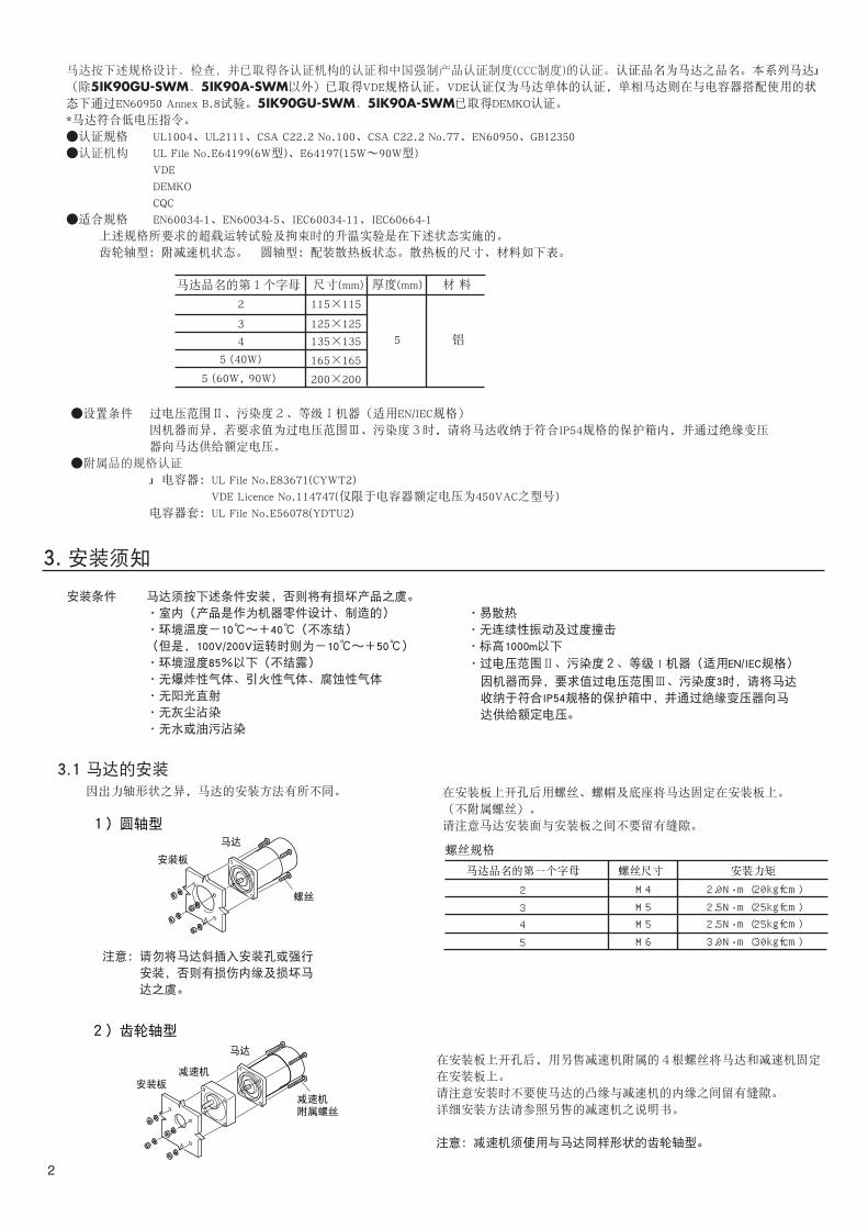
因出力轴形状之异,马达的安装方法有所不同。
1)圆轴型
2)齿轮轴型
在安装板上开孔后用螺丝、螺帽及底座将马达固定在安装板上。
(不附属螺丝)。
请注意马达安装面与安装板之间不要留有缝隙。
螺丝规格
马达品名的第一个字母 螺丝尺寸 安装力矩
·过电压范围Ⅱ、污染度2、等级 I 机器(适用EN/IEC规格)
马达
螺丝
安装板
在安装板上开孔后,用另售减速机附属的4根螺丝将马达和减速机固定
在安装板上。
请注意安装时不要使马达的凸缘与减速机的内缘之间留有缝隙。
详细安装方法请参照另售的减速机之说明书。
注意:减速机须使用与马达同样形状的齿轮轴型。
马达按下述规格设计、检查,并已取得各认证机构的认证和中国强制产品认证制度(CCC制度)的认证。认证品名为马达之品名。本系列马达 (除5IK90GU-SWM、5IK90A-SWM以外)已取得VDE规格认证。VDE认证仅为马达单体的认证,单相马达则在与电容器搭配使用的状
态下通过EN60950 Annex B.8试验。5IK90GU-SWM、5IK90A-SWM已取得DEMKO认证。
*马达符合低电压指令。
●认证规格 UL1004、UL2111、CSA C22.2 No.100、CSA C22.2 No.77、EN60950、GB12350
●认证机构 UL File No.E64199(6W型)、E64197(15W〜90W型)
VDE
DEMKO
CQC
●适合规格 EN60034-1、EN60034-5、IEC60034-11、IEC60664-1
上述规格所要求的超载运转试验及拘束时的升温实验是在下述状态实施的。
齿轮轴型:附减速机状态。 圆轴型:配装散热板状态。散热板的尺寸、材料如下表。
2
3
5 (40W)
5 (60W, 90W)
115 115
125 125
4 135 135
165 165
200 200
5
马达品名的第1个字母
铝
尺寸(mm) 厚度(mm) 材 料
●设置条件 过电压范围Ⅱ、污染度2、等级Ⅰ机器(适用EN/IEC规格)
因机器而异,若要求值为过电压范围Ⅲ、污染度3时,请将马达收纳于符合IP54规格的保护箱内,并通过绝缘变压
器向马达供给额定电压。
●附属品的规格认证
电容器:UL File No.E83671(CYWT2)
VDE Licence No.114747(仅限于电容器额定电压为450VAC之型号)
电容器套:UL File No.E56078(YDTU2)
注意:请勿将马达斜插入安装孔或强行
安装,否则有损伤内缘及损坏马
达之虞。
马达
减速机附属螺丝
减速机安装板

3.2 电容器安装须知(仅单相马达附属)
3.3 变更橡皮电缆线方向的方法(60W,90W)
4.3
请在确认附属的电容器容量是否符合马达铭板上所记载的容量后再进行安装.安装电容器时,请使用M4螺丝。
(本电容器不附属螺丝.)
注意 ·为了防止损坏安装脚座,请将螺丝的安装力矩控制在1N·m(10kgfcm)以下。
·电容器的安装位置须离开马达10cm以上,否则会引电容器发热而缩短使用寿命。
60W、90W马达的橡皮电缆线的引线方向出厂时设定为马达出力轴方向。
引线方向可转动180°。
请按下图所表示里变更引线方向。
六角孔M3螺丝
电缆线压板
橡皮电缆线
①
②
③
①拆除电缆线压板的螺丝和电缆线压板上部,将橡皮电缆线扳到相反侧
②将电缆线压板旋转180°。
③安装电缆线压板上部并用螺丝固定。
注意 为了防止橡皮电缆线的松弛与破损,请按照以下的螺丝安装力矩来进行安装。
安装力矩:0.5N·m(5kgfcm)〜0.7N·m(7kgfcm)
■附散热风扇的马达
设备 吸入
排出
10
安装附散热风扇的马达时,为了避免堵塞马达后部的散热孔,请在风扇罩后部
空出10mm以上或开换气孔.
3
4. 连接及运转
2
13
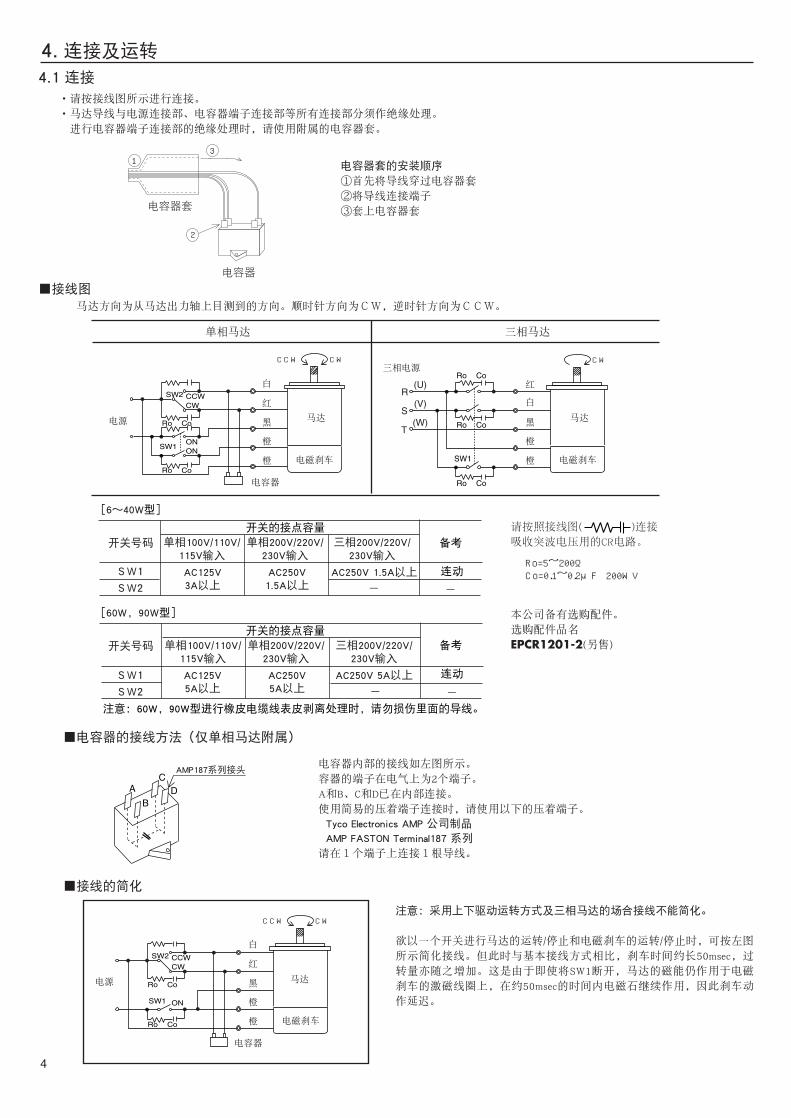
·请按接线图所示进行连接。
·马达导线与电源连接部、电容器端子连接部等所有连接部分须作绝缘处理。
进行电容器端子连接部的绝缘处理时,请使用附属的电容器套。
电容器套的安装顺序
①首先将导线穿过电容器套
②将导线连接端子
③套上电容器套
电容器
电容器套
A
B
CD
■电容器的接线方法(仅单相马达附属)
■接线的简化
AMP187系列接头
SW2
SW1
SW2
SW1
-
-
CCW CW
SW1ON
Ro Co
Ro Co
ON
SW2 CCWCW
CW
R
S
T
(U)
(V)
(W)
SW1
Ro Co
Ro Co
Ro Co
-
-
CCW CW
SW1
Ro Co
Ro Co
ON
SW2 CCWCW
4
■接线图
4.1 连接
马达方向为从马达出力轴上目测到的方向。顺时针方向为CW,逆时针方向为CCW。
单相马达 三相马达
请按照接线图( )连接
吸收突波电压用的CR电路。
本公司备有选购配件。
选购配件品名
EPCR1201-2(另售)
Ro=5~200Ω Co=0.1~ 0.2μ F
200WV
注意:60W,90W型进行橡皮电缆线表皮剥离处理时,请勿损伤里面的导线。
注意:采用上下驱动运转方式及三相马达的场合接线不能简化。
欲以一个开关进行马达的运转/停止和电磁刹车的运转/停止时,可按左图
所示简化接线。但此时与基本接线方式相比,刹车时间约长50msec,过
转量亦随之增加。这是由于即使将SW1断开,马达的磁能仍作用于电磁
刹车的激磁线圈上,在约50msec的时间内电磁石继续作用,因此刹车动
作延迟。
电源
电容器
马达
白
红
黑
橙
橙 电磁刹车
三相电源
马达
白
红
黑
橙
橙 电磁刹车
电源
电容器
马达
白
红
黑
橙
橙 电磁刹车
开关号码
开关号码
开关的接点容量
开关的接点容量
备考
连动
备考
连动
[6〜40W型]
[60W,90W型]
单相100V/110V/115V输入
单相200V/220V/230V输入
三相200V/220V/230V输入
AC125V3A以上
AC250V1.5A以上
AC250V 1.5A以上
单相100V/110V/115V输入
单相200V/220V/230V输入
三相200V/220V/230V输入
AC125V5A以上
AC250V5A以上
AC250V 5A以上
电容器内部的接线如左图所示。
容器的端子在电气上为2个端子。
A和B、C和D已在内部连接。
使用简易的压着端子连接时,请使用以下的压着端子。
Tyco Electronics AMP 公司制品
AMP FASTON Terminal187 系列
请在1个端子上连接1根导线。

4.2 运转
5
SW2 CCWCW
OFFON ON
OFF OFF
CW CW
CCW
SW1
注意 ·此产品为B种绝缘马达。
请注意运转中的马达外壳温度不能超过90℃,否则会缩短线圈及滚珠轴承的使用寿命。
马达外壳温度可通过在马达表面固定温度表的方法来测定,亦可使用热敏纸或热电藕来测量。
·请使用单相马达附属的电容器,马达起动后亦必须使电容器保持连接状态。
[SW1与SW2的时序例]此序例为基本接线图
■运转/停止
SW1用来进行马达运转/停止及电磁刹车的操作(连动)。
SW1 ON时,电磁刹车被解除、马达运转;SW1 OFF时,则电磁刹车动作、马达停止。
注意:电磁刹车动作时,由于刹车为摩擦式因此会发出摩擦音,并非异常。
■运转方向的切换
[单相马达] 将SW2扳到CW时按顺时针方向运转,扳到CCW时则为逆时针方向运转。
[三相马达] 按照接线图连接时为顺时针方向运转,只要交换U、V、W中任何两根线的连接则为逆时针方向运转。
■其他的操作方法
注意:用于上下驱动时,负载有滑落下之情形,请在确认负载状况后再进行操作。
·加快马达启动时间的方法
提前开放电磁刹车可使马达更快启动。
请在马达启动10msec之前开放电磁刹车。
·马达停止时电磁刹车的开放方法
在2根电磁刹车闭导线(橙色)之间通电则电磁刹车被解除,马达可手动启动。
5. 运转额定时间感应马达可作连续运转(连续额定)
可逆马达的可续运转时间为30分钟(30分钟额定:铭板上的记载为[30min])。
6. 过热保护功能本产品具备当马达因某种原因异常发热时能防止马达烧毁的过热保护功能。
保护方式有以下两种
■过热保护装置(马达铭板上记载为TP及TP211)
当温度上升到规定温度时,内藏的过热保护装置会自动动作,马达则会自然停止。
这时,由于电磁刹车仍保持开放状态,所以负载无法保持。请另外采取安全措施。
因是自动恢复型,所以当马达温度下降后马达会自动重新运转。检点作业等须在切断电源后实行。
■阻抗型保护器(铭板上记载为ZP)
当马达发生异常呈拘束状态时,此保护器能增大线圈的阻抗值,抑制电流输入马达以避免烧坏马达线圈。
过热保护装置的动作温度开(断电)⋯⋯⋯⋯⋯⋯130℃±5℃
关(通电)⋯⋯⋯⋯⋯⋯ 82℃±15℃
马达
运转 运转停止保持
停止保持
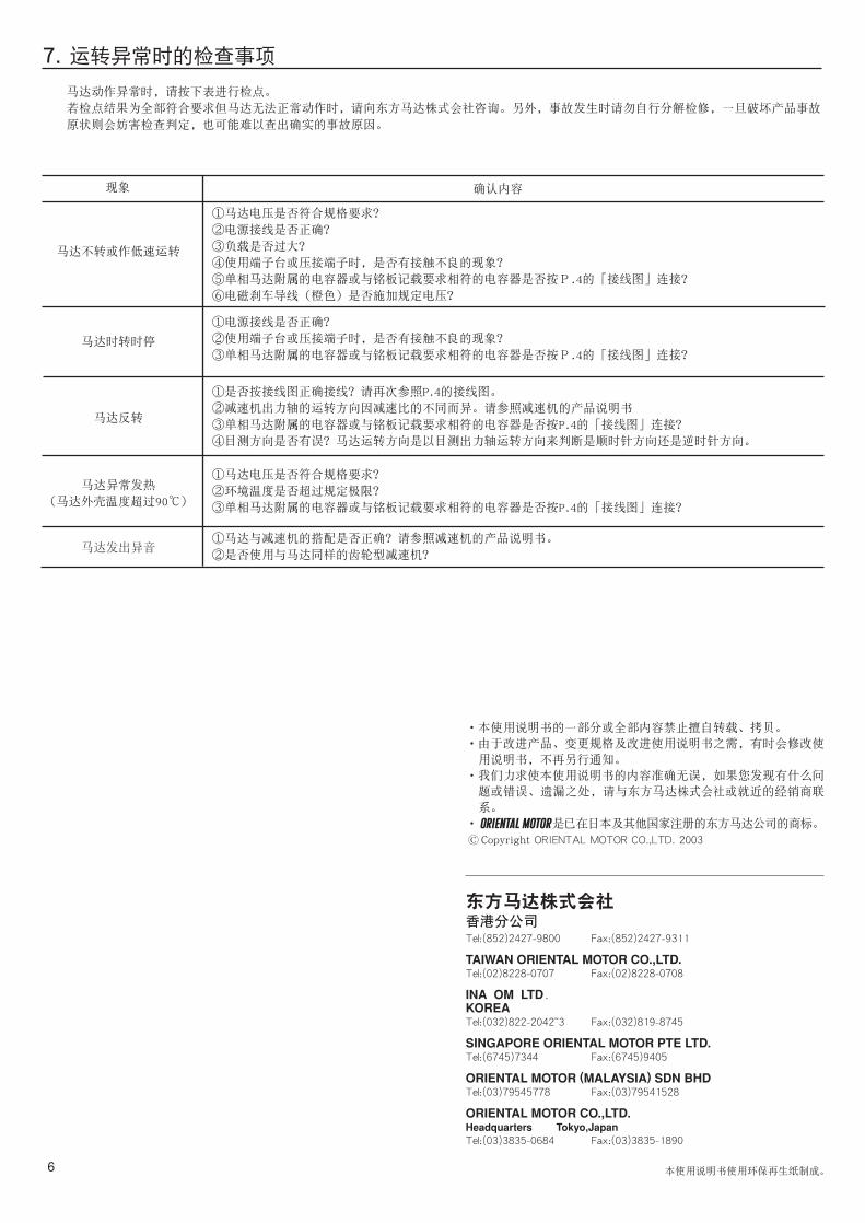
7. 运转异常时的检查事项
马达动作异常时,请按下表进行检点。
若检点结果为全部符合要求但马达无法正常动作时,请向东方马达株式会社咨询。另外,事故发生时请勿自行分解检修,一旦破坏产品事故
原状则会妨害检查判定,也可能难以查出确实的事故原因。
现象 确认内容
马达不转或作低速运转
马达时转时停
马达反转
马达异常发热
(马达外壳温度超过90℃)
马达发出异音
①马达电压是否符合规格要求?
②电源接线是否正确?
③负载是否过大?
④使用端子台或压接端子时,是否有接触不良的现象?
⑤单相马达附属的电容器或与铭板记载要求相符的电容器是否按P.4的「接线图」连接?
⑥电磁刹车导线(橙色)是否施加规定电压?
①电源接线是否正确?
②使用端子台或压接端子时,是否有接触不良的现象?
③单相马达附属的电容器或与铭板记载要求相符的电容器是否按P.4的「接线图」连接?
①是否按接线图正确接线?请再次参照P.4的接线图。
②减速机出力轴的运转方向因减速比的不同而异。请参照减速机的产品说明书
③单相马达附属的电容器或与铭板记载要求相符的电容器是否按P.4的「接线图」连接?
④目测方向是否有误?马达运转方向是以目测出力轴运转方向来判断是顺时针方向还是逆时针方向。
①马达电压是否符合规格要求?
②环境温度是否超过规定极限?
③单相马达附属的电容器或与铭板记载要求相符的电容器是否按P.4的「接线图」连接?
①马达与减速机的搭配是否正确?请参照减速机的产品说明书。
②是否使用与马达同样的齿轮型减速机?
6
·本使用说明书的一部分或全部内容禁止擅自转载、拷贝。
·由于改进产品、变更规格及改进使用说明书之需,有时会修改使
用说明书,不再另行通知。
·我们力求使本使用说明书的内容准确无误,如果您发现有什么问
题或错误、遗漏之处,请与东方马达株式会社或就近的经销商联
系。
· 是已在日本及其他国家注册的东方马达公司的商标。
Copyright ORIENTAL MOTOR CO.,LTD. 2003
东方马达株式会社香港分公司Tel:(852)2427-9800 Fax:(852)2427-9311
TAIWAN ORIENTAL MOTOR CO.,LTD.Tel:(02)8228-0707 Fax:(02)8228-0708
INA OM LTD.KOREATel:(032)822-2042~3 Fax:(032)819-8745
SINGAPORE ORIENTAL MOTOR PTE LTD.Tel:(6745)7344 Fax:(6745)9405
ORIENTAL MOTOR (MALAYSIA) SDN BHDTel:(03)79545778 Fax:(03)79541528
ORIENTAL MOTOR CO.,LTD.Headquarters Tokyo,JapanTel:(03)3835-0684 Fax:(03)3835-1890
本使用说明书使用环保再生纸制成。
Thank you for purchasing ORIENTAL MOTOR products.
Please read this operating manual thoroughly before
installing and operating the motor, and always keep
the manual where it is readily accessible.
1. Precautions1. 1 Precautions for Installation●Do not use in a place where there is flammable gas and/or corrosive gas.●When installing the motor into your equipment, ensure that the motor lead wires are fixed and do not move.
In addition, do not apply any pressure to these lead wires.●Motors for use only in equipment of protection class I .
Motore zur Verwendung in Geräten der Schutzklasse I .●The motor housing must be mounted with a screw and spring washer to the ground point of the equipment.
Die Gehäuse der Motore sind mit einer Schraube und Zahnscheibe sicher mit dem geerdeten Gehäuse des Gerätes zu verbinden.●Installation must be performed by a qualified installer.
1. 2 Precautions for Operation●The Motor case temperature can exceed 70˚C (depending on operation conditions). In case motor is
accessible during operation, please attach the following warning label so that it is clearly visible.
Warning label●Always turn off the power to the motor before conducting checks or performing work on the motor.
Thermally protected motors will restart automatically when motor temperature falls bellow a certain level.●The electromagnetic brake is designed to activate when power is removed. However, it may not arrest all loads completely. If this motor is
designed to hold in emergency situations then a second method of stopping the load must be used to ensure to load stops. If this is not used injury or machine damage may result.
2. Checking the package contents2. 1 Checking the contents
Make sure that you have received all of the items listed below.
If an accessory is missing or damaged,contact the nearest ORIENTAL MOTOR office.
-Motor……………………1 -Capacitor cap…………………1 (for only single-phase motors )
-Capacitor ………………1 (for only single-phase motors ) -This operating manual ………1
2. 2 Checking the product name and motor-capacitor combinationThis product comes in a combined set consisting of a motor and a capacitor. When the product first arrives, check the name plates to confirm thatyou have received the correct motor and capacitor combination.
■100V/110V/115V type ■200V/220V/230V type
※ The list opposite shows the pinion shaft motor. Round shaft motors are indicated by A before the hyphen.Recognized name and certified name are motor model name.
World K SeriesElectromagnetic Brake Motors
OPERATING MANUAL
<Table of contents>1. Precautions…………………………………Page1 5.Time Rating…………………………………Page52. Checking the package contents ……………Page1 6. Locked rotor burnout protection……………Page53. Installation……………………………………Page2 7. Troubleshooting……………………………Page64. Connection and Operation …………………Page4
HM-9174-2
© Copyright ORIENTAL MOTOR CO.,LTD. 2003
2RK6GN-AWMJG 2RK6GN-AWMUG 3RK15GN-AWMJG 3RK15GN-AWMUG 4RK25GN-AWMJG4RK25GN-AWMUG 5RK40GN-AWMJG 5RK40GN-AWMUG5RK60GU-AWMJG 5RK60GU-AWMUG 5RK90GU-AWMJG 5RK90GU-AWMUG
2RK6GN-AWM 2RK6GN-AWM 3RK15GN-AWM 3RK15GN-AWM 4RK25GN-AWM4RK25GN-AWM 5RK40GN-AWM 5RK40GN-AWM5RK60GU-AWM 5RK60GU-AWM 5RK90GU-AWM 5RK90GU-AWM
CH45FAULCH35FAULCH75CFAULCH60CFAULCH100CFAULCH80CFAULCH160CFAULCH120CFAULCH250CFAULCH200CFAULCH350CFAULCH300CFAUL
Model ※ Motor Model ※ Capacitor Model Model ※ Motor Model ※ Capacitor Model2RK6GN-CWMJG 2RK6GN-CWMEG 3RK15GN-CWMJG 3RK15GN-CWMEG4RK25GN-CWMJG4RK25GN-CWMEG5RK40GN-CWMJG5RK40GN-CWMEG5RK60GU-CWMJG5RK60GU-CWMEG5RK90GU-CWMJG5RK90GU-CWMEG2IK6GN-SWMG4IK25GN-SWMG5IK40GN-SWMG5IK60GU-SWMG5IK90GU-SWMG
2RK6GN-CWM 2RK6GN-CWM 3RK15GN-CWM 3RK15GN-CWM 4RK25GN-CWM4RK25GN-CWM 5RK40GN-CWM 5RK40GN-CWM5RK60GU-CWM 5RK60GU-CWM 5RK90GU-CWM 5RK90GU-CWM 2IK6GN-SWM4IK25GN-SWM5IK40GN-SWM5IK60GU-SWM5IK90GU-SWM
CH10BFAULCH08BFAULCH18BFAULCH15BFAULCH25BFAULCH20BFAULCH40BFAULCH35BFAULCH60BFAULCH50BFAULCH80BFAULCH70BFAUL
1
C
3. InstallationInstallation conditionsInstall the motor and capacitor in a location that meets the following conditions. Using the motor and capacitor in a location that does not satisfy these conditions could damage it.・Indoors (this product is designed and manufactured to be installed within another device)・Ambient temperature:-10˚C(14˚F) ~ +40˚C(104˚F) (avoid freezing)
( -10˚C(14˚F) ~+50˚C(122˚F) for 100V/200V )・Ambient humidity: 85% max. (avoid condensation)・Not exposed to explosive, flammable, or corrosive gas・Not exposed to direct sunlight・Not exposed to dust・Not exposed to water or oil・A place where heat can escape easily・Not exposed to continuous vibration or excessive impact・1,000 meters or less above sea level・Overvoltage category II , Pollution degree 2, Class I equipment (For EN/IEC standards)
When the machinery to which the motor is mounted requires overvoltage category III and pollution degree 3 specifications,install the motor in a cabinet that comply with IP54 and connect to power supply via an isolation transformer.
3.1 Mounting the motor
Installation varies with the shape of the motor’s output shaft.
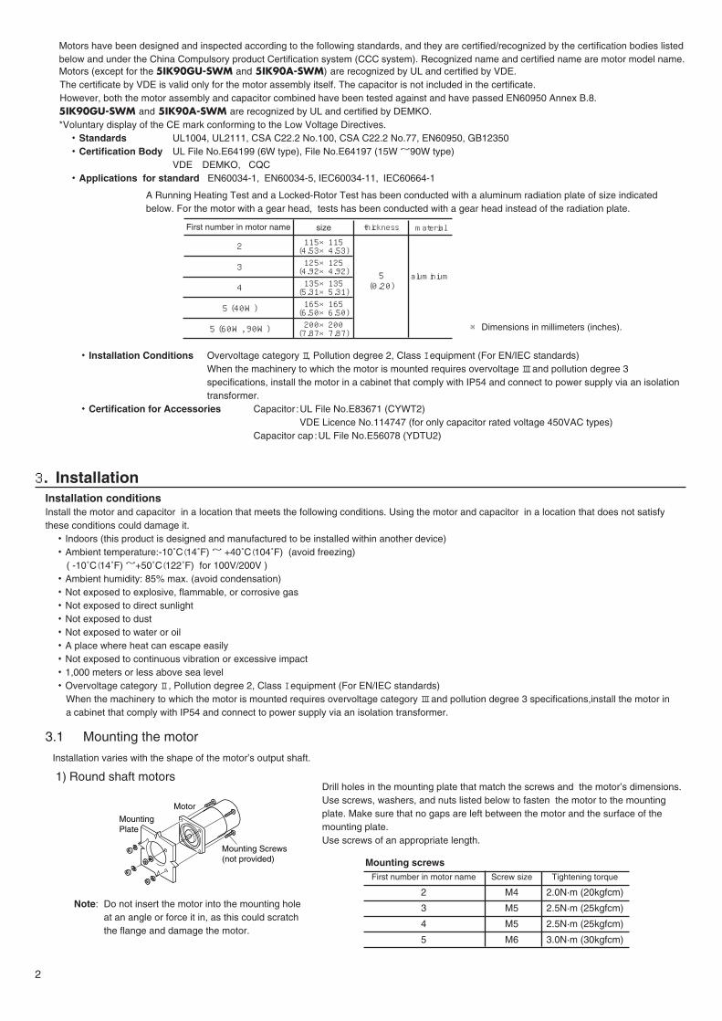
1) Round shaft motorsDrill holes in the mounting plate that match the screws and the motor’s dimensions.Use screws, washers, and nuts listed below to fasten the motor to the mountingplate. Make sure that no gaps are left between the motor and the surface of themounting plate. Use screws of an appropriate length.
Mounting screws
Note: Do not insert the motor into the mounting hole at an angle or force it in, as this could scratch the flange and damage the motor.
Motor
Mounting Screws(not provided)
MountingPlate
2
First number in motor name
2
3
4
5
Screw size
M4
M5
M5
M6
Tightening torque
2.0N·m (20kgfcm)
2.5N·m (25kgfcm)
2.5N·m (25kgfcm)
3.0N·m (30kgfcm)
Motors have been designed and inspected according to the following standards, and they are certified/recognized by the certification bodies listedbelow and under the China Compulsory product Certification system (CCC system). Recognized name and certified name are motor model name.Motors (except for the 5IK90GU-SWM and 5IK90A-SWM) are recognized by UL and certified by VDE.The certificate by VDE is valid only for the motor assembly itself. The capacitor is not included in the certificate.However, both the motor assembly and capacitor combined have been tested against and have passed EN60950 Annex B.8.5IK90GU-SWM and 5IK90A-SWM are recognized by UL and certified by DEMKO.*Voluntary display of the CE mark conforming to the Low Voltage Directives.・Standards UL1004, UL2111, CSA C22.2 No.100, CSA C22.2 No.77, EN60950, GB12350・Certification Body UL File No.E64199 (6W type), File No.E64197 (15W ~90W type)
VDE, DEMKO, CQC・Applications for standard EN60034-1, EN60034-5, IEC60034-11, IEC60664-1
A Running Heating Test and a Locked-Rotor Test has been conducted with a aluminum radiation plate of size indicatedbelow. For the motor with a gear head, tests has been conducted with a gear head instead of the radiation plate.
・Installation Conditions Overvoltage category II, Pollution degree 2, Class I equipment (For EN/IEC standards)When the machinery to which the motor is mounted requires overvoltage III and pollution degree 3 specifications, install the motor in a cabinet that comply with IP54 and connect to power supply via an isolation transformer.
・Certification for Accessories Capacitor :UL File No.E83671 (CYWT2)VDE Licence No.114747 (for only capacitor rated voltage 450VAC types)
Capacitor cap:UL File No.E56078 (YDTU2)
※ Dimensions in millimeters (inches).
First number in motor name
2
3
4
5 (40W)
5 (60W, 90W)
size
115×115(4.53×4.53)125×125(4.92×4.92)135×135(5.31×5.31)165×165(6.50×6.50)200×200(7.87×7.87)
thickness
5(0.20)
material
aluminium

3. 2 Mounting the capacitor (For only single-phase motors)
Before mounting the provided capacitor,check that the capacitor’s capacitance matches that stated on themotor’s name plate .Use M4 screws to mount the capacitor (screws not provided).Note -Do not let the screw fastening torque exceed 1 N·m (10 kgfcm) to prevent damage to the mounting feet.
-Mount capacitor at least 10 cm (3.94inches) away from the motor. If it is located closer, the life of the capacitor will be shortened.
※Dimensions in millimeters (inches).
3. 3 Changing Direction of the Cable OutletIn case of 60W and 90W type, the direction of the cable outlet is the output shaft side of the motor when shipping.
The direction of outlet can be changed by 180゚ if desired.Change the direction of the cable outlet according to following steps.
①Remove screws and upper unit of cable clamp.Put the cable toward the opposite direction.
②Turn the cable clamp to change the direction of cable outlet.
③Refasten upper unit of cable clamp with screws.
Note: Keep the tightening torque within the limits shown below to prevent
the cable from coming loose or to damage caused by excessive
tightening torque.
Screw tightening torque 0.5N·m (5kgfcm) ~ 0.7N·m (7kgfcm)
3
φ4.3
2) Pinion shaft motorDrill holes in the mounting plate that match the screws and the motor’sdimensions.Attach the motor and gearhead using the screws supplied with the gearhead (gearhead sold separately). Fasten the screws supplied with the gearhead to the mounting plate. Attach sothat no gaps are left between the motor flange surface and the gearhead pilotsection end surface.
Refer to the gearhead operation manual for further details concerning mounting(gearhead sold separately).
Note: Use the gearhead of the same type of pinion shaft as the motor.
3) Motor with cooling fanWhen mounting a motor with a cooling fan onto a device, open a ventilation hole or leave 10 millimeters (0.4inches) or more behind the fan cover
so that the cooling inlet on the back of the motor cover is not blocked.
Motor
Gearhead
Screws providedwith gearhead
MountingPlate
M3 hexagonalsocket-head screw
Cable clamp
Cable
①
②
③
(0.169)
4. Connection and Operation4. 1 Connection・Connect the motor according to the “wiring diagram” shown below.
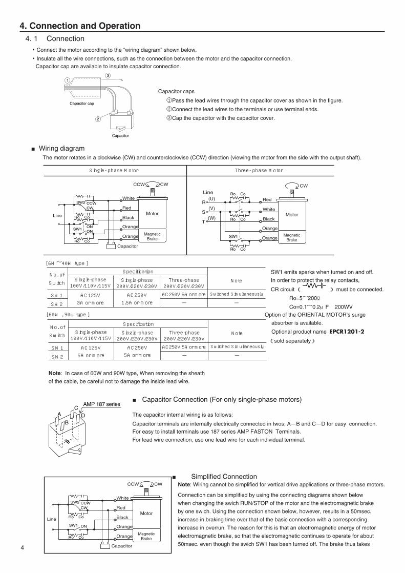
・Insulate all the wire connections, such as the connection between the motor and the capacitor connection.Capacitor cap are available to insulate capacitor connection.
Capacitor caps
①Pass the lead wires through the capacitor cover as shown in the figure.
②Connect the lead wires to the terminals or use terminal ends.
③Cap the capacitor with the capacitor cover.
■Wiring diagramThe motor rotates in a clockwise (CW) and counterclockwise (CCW) direction (viewing the motor from the side with the output shaft).
SW1 emits sparks when turned on and off.
In order to protect the relay contacts,
CR circuit ( ) must be connected.
Ro=5~200Ω
Co=0.1~0.2μF 200WVOption of the ORIENTAL MOTOR’s surge
absorber is available.
Optional product name EPCR1201-2
(sold separately)
Note: In case of 60W and 90W type, When removing the sheath
of the cable, be careful not to damage the inside lead wire.
■ Capacitor Connection (For only single-phase motors)
The capacitor internal wiring is as follows:
Capacitor terminals are internally electrically connected in twos; A-B and C-D for easy connection.For easy to install terminals use 187 series AMP FASTON Terminals.
For lead wire connection, use one lead wire for each individual terminal.
■ Simplified ConnectionNote: Wiring cannot be simplified for vertical drive applications or three-phase motors.
Connection can be simplified by using the connecting diagrams shown below
when changing the swich RUN/STOP of the motor and the electromagnetic brake
by one swich. Using the connection shown below, however, results in a 50msec.
increase in braking time over that of the basic connection with a corresponding
increase in overrun. The reason for this is that an electromagnetic energy of motor
electromagnetic brake, so that the electromagnetic continues to operate for about
50msec. even though the swich SW1 has been turned off. The brake thus takes
CCW CW
SW1ON
Ro Co
Ro Co
ON
SW2 CCWCW Red
White
Line Black
Orange
Orange
Capacitor
MagneticBrake
Motor
CW
Black
R
S
T
(U)
(V)
(W)
SW1
Ro Co
Ro Co
Ro Co
White
Orange
Red
MagneticBrake
Motor
Line
Orange
CCW CW
Red
White
Line Black
Orange
Orange
Capacitor
MagneticBrake
Motor
SW1
Ro Co
Ro Co
ON
SW2 CCWCW
2
13
Capacitor cap
Capacitor
A
B
CD
AMP 187 series
4
No. of
Switch
SW1
SW2
SpecificationSingle-phase100V/110V/115V
AC125V3A or more
Single-phase200V/220V/230V
AC250V1.5A or more
Three-phase200V/220V/230VAC250V 5A or more
-
[ 6W~40W type ]
[ 60W , 90w type ]
Note
Switched Simultaneously
-
No. of
Switch
SW1
SW2
SpecificationSingle-phase100V/110V/115V
AC125V5A or more
Single-phase200V/220V/230V
AC250V5A or more
Three-phase200V/220V/230VAC250V 5A or more
-
Note
Switched Simultaneously
-
Single- phase Motor Three- phase Motor
4. 2 OperationNote : -This motor is B type insulation motor.
Make sure that the motor case temperature does not exceed 90˚C (194˚F) during motor operation.
Operating the motor above 90˚C (194˚F) will shorten the life of the coil and the ball bearings.
Motor case temperature can be measured by fastening a thermometer to the motor’s surface, or with thermo-tape.
-Be sure to use the capacitor that comes standard with your motor.
Keep the capacitor connected all the time even after the motor has been started.
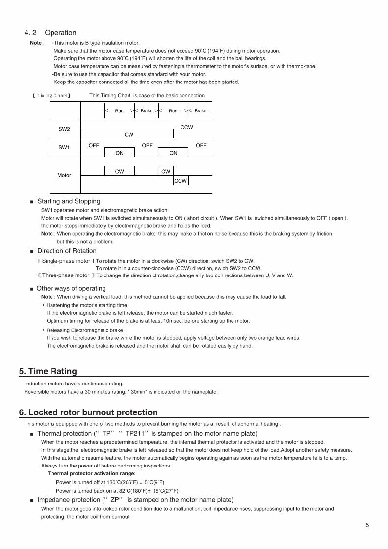
[Timing Chart] This Timing Chart is case of the basic connection
■Starting and StoppingSW1 operates motor and electromagnetic brake action.
Motor will rotate when SW1 is switched simultaneously to ON ( short circuit ). When SW1 is swiched simultaneously to OFF ( open ),
the motor stops immediately by electromagnetic brake and holds the load.
Note : When operating the electromagnetic brake, this may make a friction noise because this is the braking system by friction,
but this is not a problem.
■Direction of Rotation
[Single-phase motor]To rotate the motor in a clockwise (CW) direction, swich SW2 to CW.To rotate it in a counter-clockwise (CCW) direction, swich SW2 to CCW.
[Three-phase motor ]To change the direction of rotation,change any two connections between U, V and W.
■Other ways of operatingNote : When driving a vertical load, this method cannot be applied because this may cause the load to fall.
・Hastening the motor’s starting timeIf the electromagnetic brake is left release, the motor can be started much faster.
Optimum timing for release of the brake is at least 10msec. before starting up the motor.
・Releasing Electromagnetic brakeIf you wish to release the brake while the motor is stopped, apply voltage between only two orange lead wires.
The electromagnetic brake is released and the motor shaft can be rotated easily by hand.
5. Time RatingInduction motors have a continuous rating.
Reversible motors have a 30 minutes rating. " 30min" is indicated on the nameplate.
6. Locked rotor burnout protectionThis motor is equipped with one of two methods to prevent burning the motor as a result of abnormal heating .
■Thermal protection (“TP”“TP211”is stamped on the motor name plate)When the motor reaches a predetermined temperature, the internal thermal protector is activated and the motor is stopped.
In this stage,the electromagnetic brake is left released so that the motor does not keep hold of the load.Adopt another safety measure.
With the automatic resume feature, the motor automatically begins operating again as soon as the motor temperature falls to a temp.
Always turn the power off before performing inspections.
Thermal protector activation range:
Power is turned off at 130˚C(266˚F) ±5˚C(9˚F)
Power is turned back on at 82˚C(180˚F)±15˚C(27˚F)
■ Impedance protection (“ZP” is stamped on the motor name plate)When the motor goes into locked rotor condition due to a malfunction, coil impedance rises, suppressing input to the motor and
protecting the motor coil from burnout.
5
Run Brake BrakeRun
SW2 CCWCW
OFFON ON
OFF OFF
CW CW
CCW
SW1
Motor
ORIENTAL MOTOR U.S.A. CORP.Technical Support Line Tel:(800)468-3982Available from 7:30 AM to 5:00 PM, P.S.T.E-mail: [email protected]
ORIENTAL MOTOR (EUROPA) GmbHHeadquarters and Düsseldorf Office Tel:0211-5206700 Fax:0211-52067099Munich Office Tel:08131-59880 Fax:08131-598888Hamburg Office Tel:040-76910443 Fax:040-76910445
ORIENTAL MOTOR (UK) LTD.Tel:01256-347090 Fax:01256-347099
ORIENTAL MOTOR (FRANCE) SARLTel:01 47 86 97 50 Fax:01 47 82 45 16
ORIENTAL MOTOR ITALIA s.r.l.Tel:02-93906346 Fax:02-93906348
TAIWAN ORIENTAL MOTOR CO., LTD.Tel:(02)8228-0707 Fax:(02)8228-0708
SINGAPORE ORIENTAL MOTOR PTE LTD.Tel:(6745)7344 Fax:(6745)9405
INA OM LTD. KOREATel:(032)822-2042~3 Fax:(032)819-8745
ORIENTAL MOTOR CO., LTD.Headquarters Tokyo, JapanTel:(03)3835-0684 Fax:(03)3835-1890Hongkong officeTel:(852)2427-9800 Fax:(852)2427-9311
• Characteristics, specifications and dimensions are subject to change without notice.• Please contact your nearest ORIENTAL MOTOR office for further information.
Printed on Recycled Paper
ORIENTAL MOTOR (MALAYSIA) SDN BHDTel:(03)79545778 Fax:(03)79541528
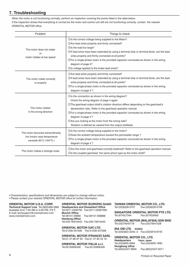
7. TroubleshootingWhen the motor is not functioning normally, perform an inspection covering the points listed in the table below.
If the inspection shows that everything is normal but the motor and control unit still are not functioning correctly, contact the nearest
ORIENTAL MOTOR office.
6
Problem
The motor does not rotate
or
motor rotates at low speed
The motor rotate correctly
or properly
The motor rotates
in the wrong direction
The motor becomes extraordinarily
hot (motor case temperature
exceeds 90˚C (194˚F) )
The motor makes a strange noise
Things to check
①Is the correct voltage being supplied to the Motor?
②Are lead wires properly and firmly connected?
③Is the load too large?
④If lead wires have been extended by using a terminal strip or terminal block, are the lead
wires properly and firmly connected at all points?
⑤For a single-phase motor is the provided capacitor connected as shown in the wiring
diagram of page 4?
⑥Is voltage applied to the brake lead wires?
①Are lead wires properly and firmly connected?
②If lead wires have been extended by using a terminal strip or terminal block, are the lead
wires properly and firmly connected at all points?
③For a single-phase motor is the provided capacitor connected as shown in the wiring
diagram of page 4 ?
①Is the connection as shown in the wiring diagram?
Check the wiring diagram of page 4 again.
②The gearhead output shaft’s rotation direction differs depending on the gearhead’s
deceleration ratio. Refer to the gearhead operation manual.
③For a single-phase motor is the provided capacitor connected as shown in the wiring
diagram of page 4 ?
④Are you looking at the motor from the wrong side?
Rotation is defined as viewed from the output shaftside.
①Is the correct voltage being supplied to the motor?
②Does the ambient temperature exceed the permissible range ?
③For a single-phase motor is the provided capacitor connected as shown in the wiring
diagram of page 4 ?
①Are the motor and gearhead correctly fastened? Refer to the gearhead operation manual.
②Is the coupled gearhead the same pinion type as the motor shaft?