GTS 10 J - Free Instruction Manuals · Robert Bosch GmbH Power Tools Division 70764...
26
Robert Bosch GmbH Power Tools Division 70764 Leinfelden-Echterdingen GERMANY www.bosch-pt.com 1 609 92A 15R (2015.01) PS / 386 EURO GTS 10 J Professional de Originalbetriebsanleitung en Original instructions fr Notice originale es Manual original pt Manual original it Istruzioni originali nl Oorspronkelijke gebruiksaanwijzing da Original brugsanvisning sv Bruksanvisning i original no Original driftsinstruks fi Alkuperäiset ohjeet el Πρωτότυπο οδηγιών χρήσης tr Orijinal işletme talimatı pl Instrukcja oryginalna cs Původní návod k používání sk Pôvodný návod na použitie hu Eredeti használati utasítás ru Оригинальное руководство по эксплуатации uk Оригінальна інструкція з експлуатації kk Пайдалану нұсқаулығының түпнұсқасы ro Instrucţiuni originale bg Оригинална инструкция mk Оригинално упатство за работа sr Originalno uputstvo za rad sl Izvirna navodila hr Originalne upute za rad et Algupärane kasutusjuhend lv Instrukcijas oriģinālvalodā lt Originali instrukcija ar fa OBJ_BUCH-1325-003.book Page 1 Monday, January 26, 2015 1:18 PM
Transcript of GTS 10 J - Free Instruction Manuals · Robert Bosch GmbH Power Tools Division 70764...
Robert Bosch GmbHPower Tools Division70764 Leinfelden-EchterdingenGERMANY
www.bosch-pt.com
1 609 92A 15R (2015.01) PS / 386 EURO
GTS 10 J Professional
de Originalbetriebsanleitungen Original instructionsfr Notice originalees Manual originalpt Manual originalit Istruzioni originalinl Oorspronkelijke gebruiksaanwijzingda Original brugsanvisningsv Bruksanvisning i originalno Original driftsinstruksfi Alkuperäiset ohjeetel Πρωτότυπο οδηγιών χρήσηςtr Orijinal işletme talimatı
pl Instrukcja oryginalnacs Původní návod k používánísk Pôvodný návod na použitiehu Eredeti használati utasításru Оригинальное руководство по
эксплуатацииuk Оригінальна інструкція з
експлуатаціїkk Пайдалану нұсқаулығының
түпнұсқасы ro Instrucţiuni originalebg Оригинална инструкцияmk Оригинално упатство за работа
sr Originalno uputstvo za radsl Izvirna navodilahr Originalne upute za radet Algupärane kasutusjuhendlv Instrukcijas oriģinālvalodālt Originali instrukcijaarfa
OBJ_BUCH-1325-003.book Page 1 Monday, January 26, 2015 1:18 PM

2 |
1 609 92A 15R | (26.1.15) Bosch Power Tools
Deutsch . . . . . . . . . . . . . . . . . . . . . . . . . . . . . . . . . . . . . . . . . Seite 15English . . . . . . . . . . . . . . . . . . . . . . . . . . . . . . . . . . . . . . . . . . Page 27Français . . . . . . . . . . . . . . . . . . . . . . . . . . . . . . . . . . . . . . . . . Page 39Español . . . . . . . . . . . . . . . . . . . . . . . . . . . . . . . . . . . . . . . . Página 51Português. . . . . . . . . . . . . . . . . . . . . . . . . . . . . . . . . . . . . . . Página 64Italiano . . . . . . . . . . . . . . . . . . . . . . . . . . . . . . . . . . . . . . . . . Pagina 76Nederlands . . . . . . . . . . . . . . . . . . . . . . . . . . . . . . . . . . . . . Pagina 89Dansk . . . . . . . . . . . . . . . . . . . . . . . . . . . . . . . . . . . . . . . . . . . Side 101Svenska . . . . . . . . . . . . . . . . . . . . . . . . . . . . . . . . . . . . . . . . . Sida 112Norsk . . . . . . . . . . . . . . . . . . . . . . . . . . . . . . . . . . . . . . . . . . . Side 123Suomi . . . . . . . . . . . . . . . . . . . . . . . . . . . . . . . . . . . . . . . . . . . . Sivu 134Ελληνικά . . . . . . . . . . . . . . . . . . . . . . . . . . . . . . . . . . . . . . . . Σελίδα 145Türkçe . . . . . . . . . . . . . . . . . . . . . . . . . . . . . . . . . . . . . . . . . Sayfa 158Polski . . . . . . . . . . . . . . . . . . . . . . . . . . . . . . . . . . . . . . . . . . Strona 170Česky . . . . . . . . . . . . . . . . . . . . . . . . . . . . . . . . . . . . . . . . . . Strana 182Slovensky. . . . . . . . . . . . . . . . . . . . . . . . . . . . . . . . . . . . . . . Strana 193Magyar . . . . . . . . . . . . . . . . . . . . . . . . . . . . . . . . . . . . . . . . . . Oldal 205Русский . . . . . . . . . . . . . . . . . . . . . . . . . . . . . . . . . . . . . Страница 217Українська. . . . . . . . . . . . . . . . . . . . . . . . . . . . . . . . . . . Сторінка 230Қазақша. . . . . . . . . . . . . . . . . . . . . . . . . . . . . . . . . . . . . . . . . . .Бет 243Română . . . . . . . . . . . . . . . . . . . . . . . . . . . . . . . . . . . . . . . . Pagina 255Български . . . . . . . . . . . . . . . . . . . . . . . . . . . . . . . . . . . Страница 267Македонски . . . . . . . . . . . . . . . . . . . . . . . . . . . . . . . . . . . Страна 280Srpski . . . . . . . . . . . . . . . . . . . . . . . . . . . . . . . . . . . . . . . . . . Strana 293Slovensko . . . . . . . . . . . . . . . . . . . . . . . . . . . . . . . . . . . . . . . Stran 304Hrvatski . . . . . . . . . . . . . . . . . . . . . . . . . . . . . . . . . . . . . . Stranica 315Eesti . . . . . . . . . . . . . . . . . . . . . . . . . . . . . . . . . . . . . . . . . Lehekülg 326Latviešu . . . . . . . . . . . . . . . . . . . . . . . . . . . . . . . . . . . . . . Lappuse 337Lietuviškai . . . . . . . . . . . . . . . . . . . . . . . . . . . . . . . . . . . . Puslapis 349
. . . . . . . . . . . . . . . . . . . . . . . . . . . . . . 372 . . . . . . . . . . . . . . . . . . . . . . . . . . . . . . 385
OBJ_BUCH-1325-003.book Page 2 Monday, January 26, 2015 1:18 PM
| 3
Bosch Power Tools 1 609 92A 15R | (26.1.15)
GTS 10 J
1 2 3 4 5
4
21
22
23
4
12
13
6.1* 7 8.1 9 10
1416 1215
11
17181920
6.2*
8.2
OBJ_BUCH-1325-003.book Page 3 Monday, January 26, 2015 1:18 PM
1 609 92A 15R | (26.1.15) Bosch Power Tools
4 |
11 70 24 25 26 27 28 2
30 12 30 2933 12 3132
OBJ_BUCH-1325-003.book Page 4 Monday, January 26, 2015 1:18 PM
| 5
Bosch Power Tools 1 609 92A 15R | (26.1.15)
24 34A
* *
OBJ_BUCH-1325-003.book Page 5 Monday, January 26, 2015 1:18 PM
1 609 92A 15R | (26.1.15) Bosch Power Tools
6 |
E2E1
DC
B* 6.1* 6.2*8.1 8.2
2525
11
10
5
103738
35
39
28
36
38
5
3
3
40
53
21
OBJ_BUCH-1325-003.book Page 6 Monday, January 26, 2015 1:18 PM
| 7
Bosch Power Tools 1 609 92A 15R | (26.1.15)
I
HG
F
GTA 60 W GTA 600
31
7
3212
12
41
31
OBJ_BUCH-1325-003.book Page 7 Monday, January 26, 2015 1:18 PM
1 609 92A 15R | (26.1.15) Bosch Power Tools
8 |
LK
J4J3
J2J124
45
48
3
26 44 42
46max. 5 mm
47
49
50
6.x*
43
18 17
22
OBJ_BUCH-1325-003.book Page 8 Monday, January 26, 2015 1:18 PM
| 9
Bosch Power Tools 1 609 92A 15R | (26.1.15)
PO
N
26
M
37 1026
51
10
14
3527
25
14
1
15
1 2
36,6 cm
OBJ_BUCH-1325-003.book Page 9 Monday, January 26, 2015 1:18 PM
1 609 92A 15R | (26.1.15) Bosch Power Tools
10 |
S
R
Q2Q120
20
52
10 37 23
5
3
10
5328
49
OBJ_BUCH-1325-003.book Page 10 Monday, January 26, 2015 1:18 PM
| 11
Bosch Power Tools 1 609 92A 15R | (26.1.15)
UU
T2T158
5754 1718
55 47 56
59 59
60 60
OBJ_BUCH-1325-003.book Page 11 Monday, January 26, 2015 1:18 PM
1 609 92A 15R | (26.1.15) Bosch Power Tools
12 |
Y2Y1
XW
V
66
27
31
6364
61
38
62
1 24
51
65
336.x*
71
35
OBJ_BUCH-1325-003.book Page 12 Monday, January 26, 2015 1:18 PM
| 13
Bosch Power Tools 1 609 92A 15R | (26.1.15)
Y6
Y5
Y4Y3
30 3037
6821
68 64
68
69
3
67 23 22
10
OBJ_BUCH-1325-003.book Page 13 Monday, January 26, 2015 1:18 PM
1 609 92A 15R | (26.1.15) Bosch Power Tools
14 |
Z
OBJ_BUCH-1325-003.book Page 14 Monday, January 26, 2015 1:18 PM
English | 27
Bosch Power Tools 1 609 92A 15R | (26.1.15)
EnglishSafety NotesGeneral Power Tool Safety Warnings
When using electric tools basic safety precautions should always be followed
to reduce the risk of fire, electric shock and personal injury in-cluding the following.Read all these instructions before attempting to operate this product and save these instructions.The term “power tool” in the warnings refers to your mains-operated (corded) power tool or battery-operated (cordless) power tool.
Work area safety Keep work area clean and well lit. Cluttered or dark areas
invite accidents. Do not operate power tools in explosive atmospheres,
such as in the presence of flammable liquids, gases or dust. Power tools create sparks which may ignite the dust or fumes.
Keep children and bystanders away while operating a power tool. Distractions can cause you to lose control.
Electrical safety Power tool plugs must match the outlet. Never modify
the plug in any way. Do not use any adapter plugs with earthed (grounded) power tools. Unmodified plugs and matching outlets will reduce risk of electric shock.
Avoid body contact with earthed or grounded surfaces, such as pipes, radiators, ranges and refrigerators. There is an increased risk of electric shock if your body is earthed or grounded.
Do not expose power tools to rain or wet conditions. Water entering a power tool will increase the risk of electric shock.
Do not abuse the cord. Never use the cord for carrying, pulling or unplugging the power tool. Keep cord away from heat, oil, sharp edges and moving parts. Damaged or entangled cords increase the risk of electric shock.
When operating a power tool outdoors, use an exten-sion cord suitable for outdoor use. Use of a cord suitable for outdoor use reduces the risk of electric shock.
If operating a power tool in a damp location is unavoid-able, use a residual current device (RCD) protected supply. Use of an RCD reduces the risk of electric shock.
Personal safety Stay alert, watch what you are doing and use common
sense when operating a power tool. Do not use a power tool while you are tired or under the influence of drugs, alcohol or medication. A moment of inattention while op-erating power tools may result in serious personal injury.
Use personal protective equipment. Always wear eye protection. Protective equipment such as dust mask, non-skid safety shoes, hard hat, or hearing protection used for appropriate conditions will reduce personal injuries.
Prevent unintentional starting. Ensure the switch is in the off-position before connecting to power source and/or battery pack, picking up or carrying the tool. Carrying power tools with your finger on the switch or en-ergising power tools that have the switch on invites acci-dents.
Remove any adjusting key or wrench before turning the power tool on. A wrench or a key left attached to a ro-tating part of the power tool may result in personal injury.
Do not overreach. Keep proper footing and balance at all times. This enables better control of the power tool in unexpected situations.
Dress properly. Do not wear loose clothing or jewel-lery. Keep your hair, clothing and gloves away from moving parts. Loose clothes, jewellery or long hair can be caught in moving parts.
If devices are provided for the connection of dust ex-traction and collection facilities, ensure these are con-nected and properly used. Use of dust collection can re-duce dust-related hazards.
Power tool use and care Do not force the power tool. Use the correct power tool
for your application. The correct power tool will do the job better and safer at the rate for which it was designed.
Do not use the power tool if the switch does not turn it on and off. Any power tool that cannot be controlled with the switch is dangerous and must be repaired.
Disconnect the plug from the power source and/or the battery pack from the power tool before making any adjustments, changing accessories, or storing power tools. Such preventive safety measures reduce the risk of starting the power tool accidentally.
Store idle power tools out of the reach of children and do not allow persons unfamiliar with the power tool or these instructions to operate the power tool. Power tools are dangerous in the hands of untrained users.
Maintain power tools. Check for misalignment or bind-ing of moving parts, breakage of parts and any other condition that may affect the power tool’s operation. If damaged, have the power tool repaired before use. Many accidents are caused by poorly maintained power tools.
Keep cutting tools sharp and clean. Properly maintained cutting tools with sharp cutting edges are less likely to bind and are easier to control.
Use the power tool, accessories and tool bits etc. in ac-cordance with these instructions, taking into account the working conditions and the work to be performed. Use of the power tool for operations different from those intended could result in a hazardous situation.
Service Have your power tool serviced by a qualified repair per-
son using only identical replacement parts. This will en-sure that the safety of the power tool is maintained.
OBJ_BUCH-1325-003.book Page 27 Monday, January 26, 2015 1:18 PM
28 | English
1 609 92A 15R | (26.1.15) Bosch Power Tools
Safety Warnings for Table Saws Never stand on the power tool. Serious injuries can occur
when the power tool tips over or when inadvertently com-ing into contact with the saw blade.
Take care that the blade guard operates properly and can move freely. Always adjust the blade guard in such a manner that it faces loosely against the workpiece when sawing. Never clamp the blade guard when it is open.
Keep hands away from the cutting area while the ma-chine is running. Danger of injury when coming in contact with the saw blade.
Never reach behind the saw blade in order to hold the workpiece, remove saw dust/wood chips or for any oth-er reason. The clearance of your hand to the rotating saw blade is too small.
Guide the workpiece against the saw blade only when the machine is switched on. Otherwise there is damage of kickback, when the saw blade becomes wedged in the workpiece.
Keep handles dry, clean, and free from oil and grease. Greasy, oily handles are slippery causing loss of control.
Operate the power tool only when the work area to the workpiece is clear of any adjusting tools, wood chips, etc. Small pieces of wood or other objects that come in contact with the rotating saw blade can strike the operator with high speed.
Only saw one workpiece at a time. Workpieces placed on top or aside of each other can cause the saw blade to jam or the workpieces to move against each other while saw-ing.
Always use the parallel guide or the angle guide. This improves the cutting accuracy and reduces the possibility of saw blade binding.
Use the machine for grooving or rebating only with an appropriately suitable protective device (e. g. a tunnel blade guard).
Do not use the machine for cutting slots (stopped grooves).
Use the machine only for cutting the materials listed under Intended Use. Otherwise, the machine can be sub-ject to overload.
If the saw blade should become jammed, switch the ma-chine off and hold the workpiece until the saw blade comes to a complete stop. To prevent kickback, the workpiece may not be moved until after the machine has come to a complete stop. Correct the cause for the jamming of the saw blade before restarting the machine.
Do not use dull, cracked, bent or damaged saw blades. Unsharpened or improperly set saw blades produce nar-row kerf causing excessive friction, blade binding and kick-back.
Always use blades with correct size and shape (dia-mond versus round) of arbour holes. Blades that do not match the mounting hardware of the saw will run eccentri-cally, causing loss of control.
Do not use high speed steel (HSS) saw blades. Such saw blades can easily break.
Do not touch the saw blade after working before it has cooled. The saw blade becomes very hot while working.
Keep your workplace clean. Blends of materials are par-ticularly dangerous. Dust from light alloys can burn or ex-plode.
Never operate the machine without the insert plate. Replace a defective insert plate. Without flawless insert plates, injuries are possible from the saw blade.
Check the cable regularly and have a damaged cable re-paired only through an authorised customer service agent for Bosch power tools. Replace damaged exten-sion cables. This will ensure that the safety of the power tool is maintained.
Store the machine in a safe manner when not being used. The storage location must be dry and lockable. This prevents the machine from storage damage, and from being operated by untrained persons.
Never leave the machine before it has come to a com-plete stop. Cutting tools that are still running can cause in-juries.
Never use the machine with a damaged cable. Do not touch the damaged cable and pull the mains plug when the cable is damaged while working. Damaged cables in-crease the risk of an electric shock.
Products sold in GB only: Your product is fitted with a BS 1363/A approved electric plug with internal fuse (ASTA approved to BS 1362).If the plug is not suitable for your socket outlets, it should be cut off and an appropriate plug fitted in its place by an author-ised customer service agent. The replacement plug should have the same fuse rating as the original plug.The severed plug must be disposed of to avoid a possible shock hazard and should never be inserted into a mains sock-et elsewhere.Products sold in AUS and NZ only: Use a residual current de-vice (RCD) with a rated residual current of 30 mA or less.
SymbolsThe following symbols can be important for the operation of your power tool. Please memorise the symbols and their meanings. The correct interpretation of the symbols helps you operate the power tool better and more secure.
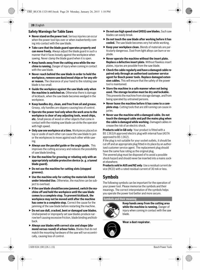
Symbols and their meaningKeep hands away from the cutting area while the machine is running. Danger of injury when coming in contact with the saw blade.
Wear a dust respirator.
OBJ_BUCH-1325-003.book Page 28 Monday, January 26, 2015 1:18 PM
English | 29
Bosch Power Tools 1 609 92A 15R | (26.1.15)
Product Description and Specifica-tions
Read all safety warnings and all instruc-tions. Failure to follow the warnings and in-structions may result in electric shock, fire and/or serious injury.
Intended UseThe power tool is intended as a stationary machine for making straight lengthways and crossways cuts in hard and soft-wood, as well as in particle and fibre board. In this, mitre an-gles from –60° to +60 ° as well as bevel angles from –2° to 47° are possible.When using appropriate saw blades, sawing aluminium pro-files and plastic is also possible.
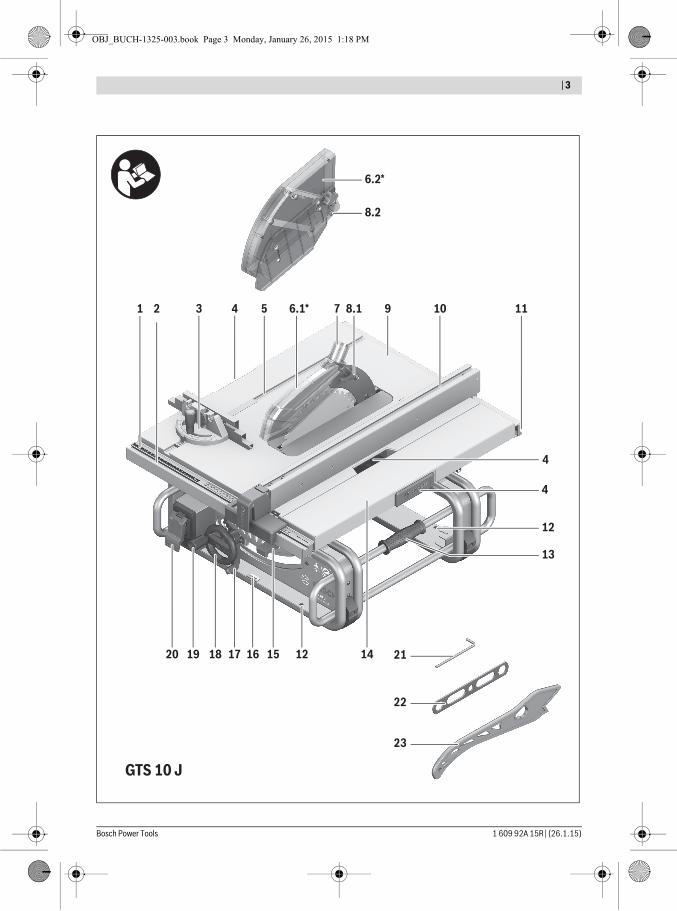
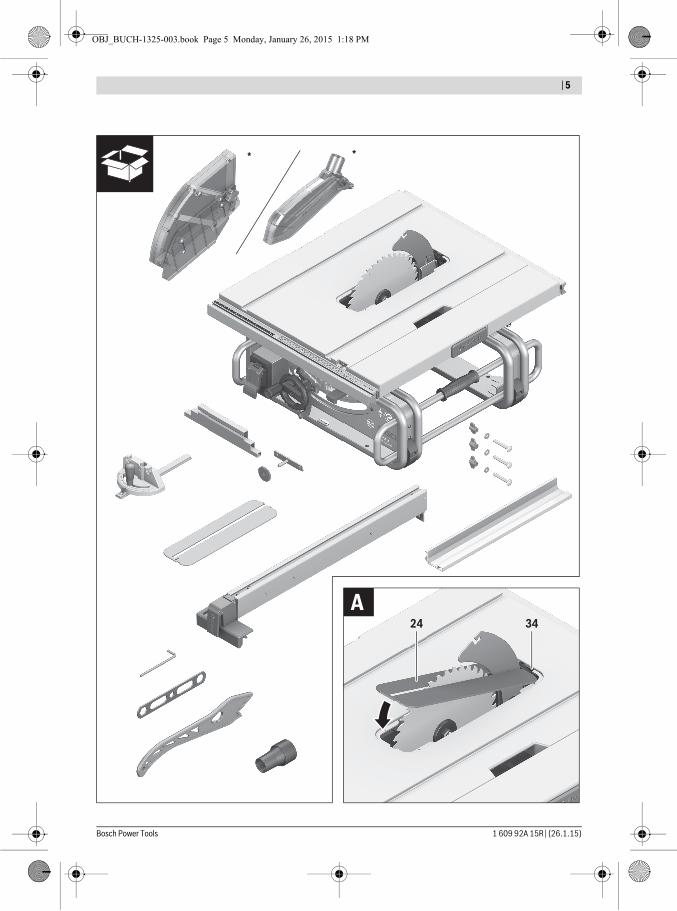
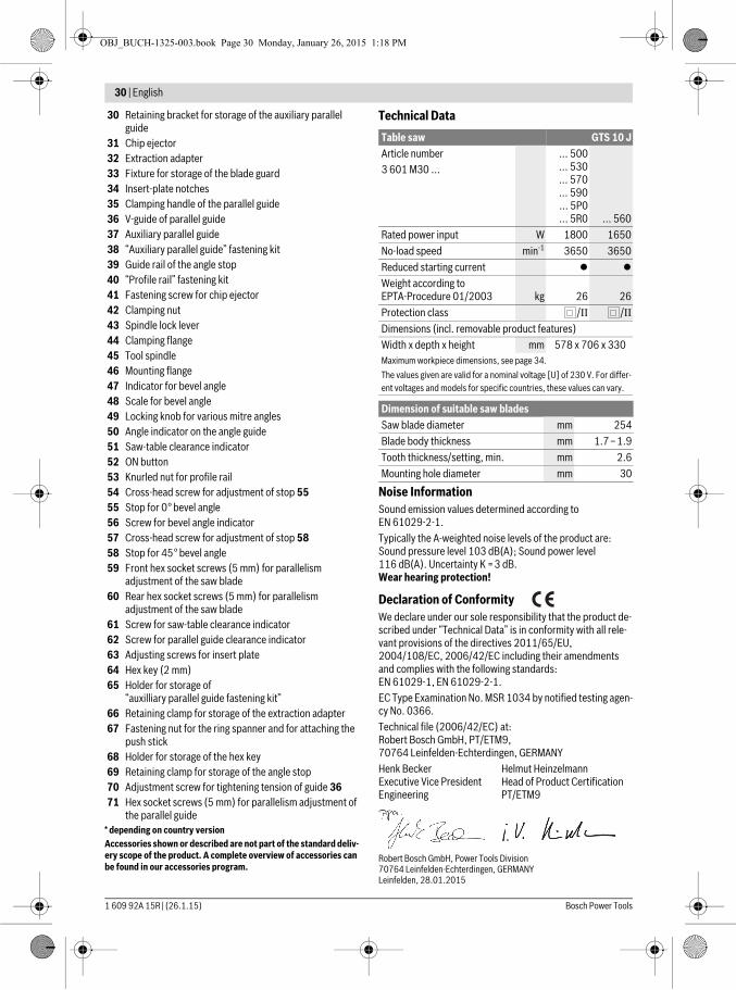
Product FeaturesThe numbering of the components shown refers to the repre-sentation of the power tool on the graphic pages.
1 Scale for clearance of the saw blade to the parallel guide 10
2 Guide groove for parallel guide 103 Angle stop4 Recessed handles5 Guide groove for angle stop
6.1 Blade guard with clamping lever *6.2 Blade guard with clamping screw and side protector*
7 Vacuum connection on the blade guard8.1 Clamping lever for locking blade guard 6.18.2 Clamping screw for locking blade guard 6.2
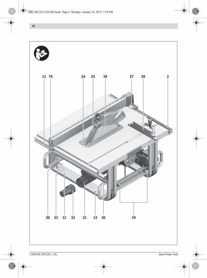
9 Saw table10 Parallel guide11 V-guide groove on saw table for parallel guide12 Mounting holes13 Carrying handle14 Saw-table extension15 Tensioning lever for saw-table extension16 Fastening bracket for saw stand GTA 60017 Locking lever for adjustment of bevel angles18 Handwheel19 Crank for lowering and raising the saw blade20 Safety flap of On/Off switch21 Hex key (5 mm)22 Ring spanner (23 mm)23 Push stick24 Insert plate25 Riving knife26 Saw blade27 Lens28 Profile rail29 Cable holder
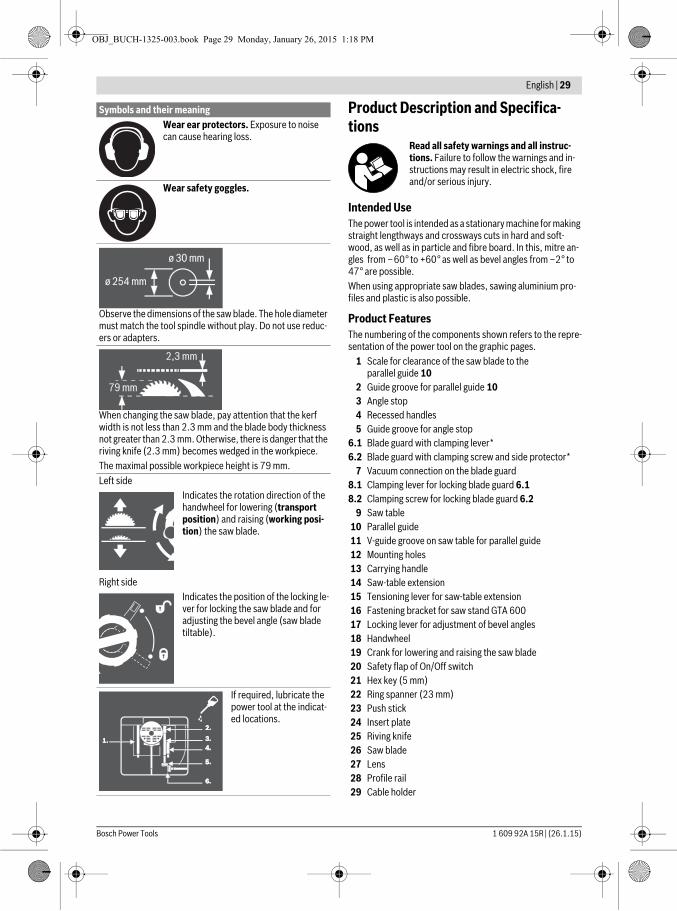
Wear ear protectors. Exposure to noise can cause hearing loss.
Wear safety goggles.
Observe the dimensions of the saw blade. The hole diameter must match the tool spindle without play. Do not use reduc-ers or adapters.
When changing the saw blade, pay attention that the kerf width is not less than 2.3 mm and the blade body thickness not greater than 2.3 mm. Otherwise, there is danger that the riving knife (2.3 mm) becomes wedged in the workpiece.The maximal possible workpiece height is 79 mm.Left side
Indicates the rotation direction of the handwheel for lowering (transport position) and raising (working posi-tion) the saw blade.
Right sideIndicates the position of the locking le-ver for locking the saw blade and for adjusting the bevel angle (saw blade tiltable).
If required, lubricate the power tool at the indicat-ed locations.
Symbols and their meaning
OBJ_BUCH-1325-003.book Page 29 Monday, January 26, 2015 1:18 PM
30 | English
1 609 92A 15R | (26.1.15) Bosch Power Tools
30 Retaining bracket for storage of the auxiliary parallel guide
31 Chip ejector32 Extraction adapter33 Fixture for storage of the blade guard34 Insert-plate notches35 Clamping handle of the parallel guide36 V-guide of parallel guide 37 Auxiliary parallel guide38 “Auxiliary parallel guide” fastening kit39 Guide rail of the angle stop40 “Profile rail” fastening kit41 Fastening screw for chip ejector42 Clamping nut43 Spindle lock lever44 Clamping flange45 Tool spindle46 Mounting flange47 Indicator for bevel angle48 Scale for bevel angle49 Locking knob for various mitre angles50 Angle indicator on the angle guide51 Saw-table clearance indicator52 ON button53 Knurled nut for profile rail54 Cross-head screw for adjustment of stop 5555 Stop for 0° bevel angle56 Screw for bevel angle indicator57 Cross-head screw for adjustment of stop 5858 Stop for 45 ° bevel angle59 Front hex socket screws (5 mm) for parallelism
adjustment of the saw blade60 Rear hex socket screws (5 mm) for parallelism
adjustment of the saw blade61 Screw for saw-table clearance indicator62 Screw for parallel guide clearance indicator63 Adjusting screws for insert plate64 Hex key (2 mm)65 Holder for storage of
“auxilliary parallel guide fastening kit”66 Retaining clamp for storage of the extraction adapter67 Fastening nut for the ring spanner and for attaching the
push stick68 Holder for storage of the hex key69 Retaining clamp for storage of the angle stop70 Adjustment screw for tightening tension of guide 3671 Hex socket screws (5 mm) for parallelism adjustment of
the parallel guide* depending on country versionAccessories shown or described are not part of the standard deliv-ery scope of the product. A complete overview of accessories can be found in our accessories program.
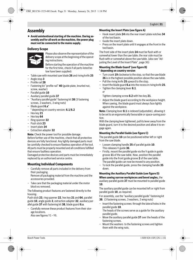
Technical Data
Noise InformationSound emission values determined according to EN 61029-2-1.Typically the A-weighted noise levels of the product are: Sound pressure level 103 dB(A); Sound power level 116 dB(A). Uncertainty K =3 dB.Wear hearing protection!
Declaration of ConformityWe declare under our sole responsibility that the product de-scribed under “Technical Data” is in conformity with all rele-vant provisions of the directives 2011/65/EU, 2004/108/EC, 2006/42/EC including their amendments and complies with the following standards: EN 61029-1, EN 61029-2-1.EC Type Examination No. MSR 1034 by notified testing agen-cy No. 0366.Technical file (2006/42/EC) at:Robert Bosch GmbH, PT/ETM9,70764 Leinfelden-Echterdingen, GERMANY
Robert Bosch GmbH, Power Tools Division70764 Leinfelden-Echterdingen, GERMANYLeinfelden, 28.01.2015
Table saw GTS 10 JArticle number3 601 M30 ...
... 500 ... 530 ... 570 ... 590 ... 5P0 ... 5R0 ... 560
Rated power input W 1800 1650No-load speed min-1 3650 3650Reduced starting current
Weight according to EPTA-Procedure 01/2003 kg 26 26Protection class /II /IIDimensions (incl. removable product features)Width x depth x height mm 578 x 706 x 330Maximum workpiece dimensions, see page 34.The values given are valid for a nominal voltage [U] of 230 V. For differ-ent voltages and models for specific countries, these values can vary.
Dimension of suitable saw bladesSaw blade diameter mm 254Blade body thickness mm 1.7–1.9Tooth thickness/setting, min. mm 2.6Mounting hole diameter mm 30
Henk BeckerExecutive Vice PresidentEngineering
Helmut HeinzelmannHead of Product CertificationPT/ETM9
OBJ_BUCH-1325-003.book Page 30 Monday, January 26, 2015 1:18 PM
English | 31
Bosch Power Tools 1 609 92A 15R | (26.1.15)
Assembly Avoid unintentional starting of the machine. During as-
sembly and for all work on the machine, the power plug must not be connected to the mains supply.
Delivery ScopePlease also observe the representation of the delivery scope at the beginning of the operat-ing instructions.Before starting the operation of the machine for the first time, check if all parts listed be-low have been supplied:
– Table saw with mounted saw blade 26 and riving knife 25– Angle stop 3– Profile rail 28– Fastening kit “profile rail” 40 (guide plate, knurled nut,
screw, washer)– Parallel guide 10– Auxiliary parallel guide 37– “Auxiliary parallel guide” fastening kit 38 (3 fastening
screws, 3 washers, 3 wing nuts)– Blade guard 6.x*
* depending on country version: 6.1/6.2– Hex key 21– Hex key 64– Ring spanner 22– Push stick 23– Insert plate 24– Extraction adapter 32Note: Check the power tool for possible damage.Before further use of the machine, check that all protective devices are fully functional. Any lightly damaged parts must be carefully checked to ensure flawless operation of the tool. All parts must be properly mounted and all conditions fulfilled that ensure faultless operation.Damaged protective devices and parts must be immediately replaced by an authorised service centre.
Mounting Individual Components– Carefully remove all parts included in the delivery from
their packaging.Remove all packaging material from the machine and the accessories provided.
– Take care that the packaging material under the motor block es removed.
The following product features are fastened directly to the housing:Push stick 23, ring spanner 22, hex key 21 and 64, parallel guide 10, angle guide 3, extraction adapter 32, auxiliary par-allel guide 37 with fastening kit 38, blade guard 6.x.– Carefully remove these product features from their stor-
age locations.Also see figures Y1–Y6.
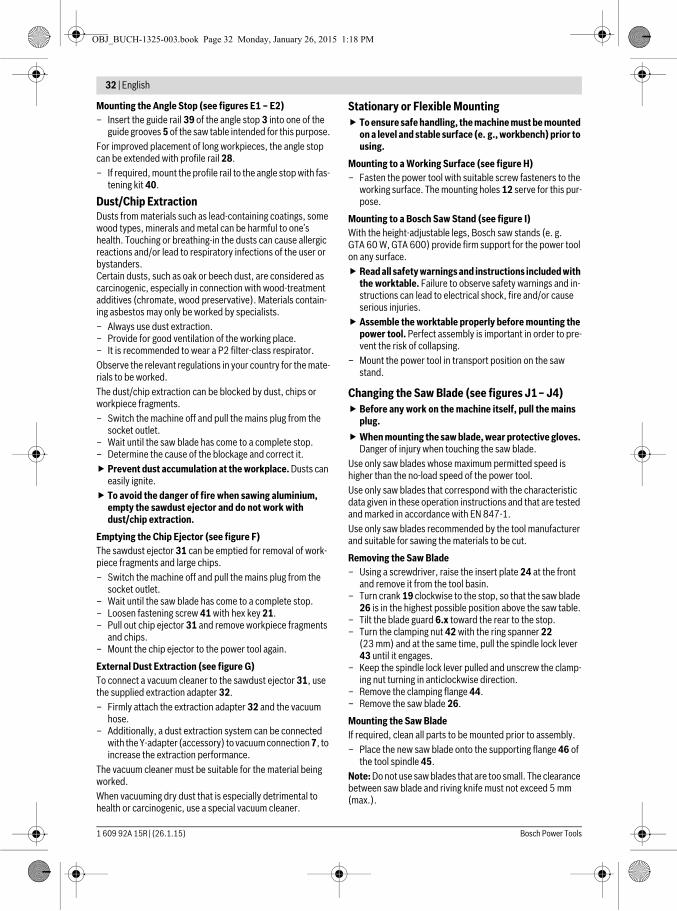
Mounting the Insert Plate (see figure A)– Hook insert plate 24 into the rear insert-plate notches 34
of the tool basin.– Guide the insert plate down.– Press on the insert plate until it engages at the front in the
tool basin.The front side of the insert plate 24 must be flush with or somewhat lower than the saw table; the rear side must be flush with or somewhat above the saw table. (also see “Ad-justing the Level of the Insert Plate”, page 36)
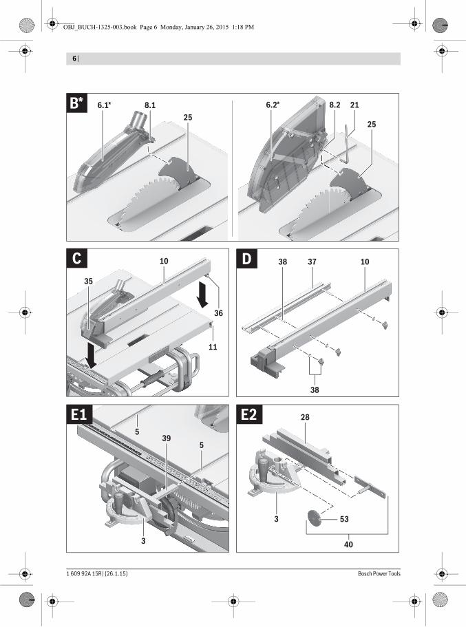
Mounting the Blade Guard* (see figure B)* depending on country version– Turn crank 19 clockwise to the stop, so that the saw blade
26 is in the highest possible position above the saw table.– Pull the riving knife 25 upward to the stop.– Insert the blade guard 6.x into the recess in riving knife 25.– Tighten the clamping lever 8.1.
orTighten clamping screw 8.2 with hex key 21.
– Adjust the blade guard according to the workpiece height.When sawing, the blade guard must always face lightly against the workpiece.
Note: Clamping lever 8.1 is indexed (adjustable), allowing it to be set to an ergonomically favourable or space-saving posi-tion.With the clamping lever tightened, pull its lever away from the blade guard, turn it to the desired position and allow it to en-gage again.
Mounting the Parallel Guide (see figure C)The parallel guide 10 can be positioned either left or right from the saw blade.– Loosen clamping handle 35 of parallel guide 10.
This releases V-guide 36.– Firstly, mount the parallel guide via the V-guide in guide
groove 11 of the saw table. Now, position the parallel guide into the front guide groove 2 of the saw table.The parallel guide can now be moved to any position.
– To lock the parallel guide, press the clamping handle 35 down.
Mounting the Auxiliary Parallel Guide (see figure D)When sawing narrow workpieces and bevel angles, the auxiliary parallel guide 37 must be mounted to parallel guide 10.The auxiliary parallel guide can be mounted left or right from parallel guide 10, as required.For assembly, use the “auxiliary parallel guide” fastening kit 38. (3 fastening screws, 3 washers, 3 wing nuts)– Insert the fastening screws through the lateral holes in the
parallel guide 10.The heads of the screws serve as a guide for the auxiliary parallel guide.
– Move the auxiliary parallel guide 37 over the heads of the fastening screws.
– Mount the washers to the fastening screws and tighten them with the wing nuts.
OBJ_BUCH-1325-003.book Page 31 Monday, January 26, 2015 1:18 PM
32 | English
1 609 92A 15R | (26.1.15) Bosch Power Tools
Mounting the Angle Stop (see figures E1 – E2)– Insert the guide rail 39 of the angle stop 3 into one of the
guide grooves 5 of the saw table intended for this purpose.For improved placement of long workpieces, the angle stop can be extended with profile rail 28.– If required, mount the profile rail to the angle stop with fas-
tening kit 40.
Dust/Chip ExtractionDusts from materials such as lead-containing coatings, some wood types, minerals and metal can be harmful to one’s health. Touching or breathing-in the dusts can cause allergic reactions and/or lead to respiratory infections of the user or bystanders.Certain dusts, such as oak or beech dust, are considered as carcinogenic, especially in connection with wood-treatment additives (chromate, wood preservative). Materials contain-ing asbestos may only be worked by specialists.– Always use dust extraction.– Provide for good ventilation of the working place.– It is recommended to wear a P2 filter-class respirator.Observe the relevant regulations in your country for the mate-rials to be worked.The dust/chip extraction can be blocked by dust, chips or workpiece fragments.– Switch the machine off and pull the mains plug from the
socket outlet.– Wait until the saw blade has come to a complete stop.– Determine the cause of the blockage and correct it. Prevent dust accumulation at the workplace. Dusts can
easily ignite. To avoid the danger of fire when sawing aluminium,
empty the sawdust ejector and do not work with dust/chip extraction.
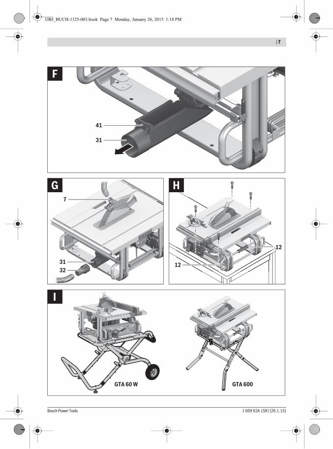
Emptying the Chip Ejector (see figure F)The sawdust ejector 31 can be emptied for removal of work-piece fragments and large chips.– Switch the machine off and pull the mains plug from the
socket outlet.– Wait until the saw blade has come to a complete stop.– Loosen fastening screw 41 with hex key 21.– Pull out chip ejector 31 and remove workpiece fragments
and chips.– Mount the chip ejector to the power tool again.
External Dust Extraction (see figure G)To connect a vacuum cleaner to the sawdust ejector 31, use the supplied extraction adapter 32.– Firmly attach the extraction adapter 32 and the vacuum
hose.– Additionally, a dust extraction system can be connected
with the Y-adapter (accessory) to vacuum connection 7, to increase the extraction performance.
The vacuum cleaner must be suitable for the material being worked.When vacuuming dry dust that is especially detrimental to health or carcinogenic, use a special vacuum cleaner.
Stationary or Flexible Mounting To ensure safe handling, the machine must be mounted
on a level and stable surface (e. g., workbench) prior to using.
Mounting to a Working Surface (see figure H)– Fasten the power tool with suitable screw fasteners to the
working surface. The mounting holes 12 serve for this pur-pose.
Mounting to a Bosch Saw Stand (see figure I)With the height-adjustable legs, Bosch saw stands (e. g. GTA 60 W, GTA 600) provide firm support for the power tool on any surface. Read all safety warnings and instructions included with
the worktable. Failure to observe safety warnings and in-structions can lead to electrical shock, fire and/or cause serious injuries.
Assemble the worktable properly before mounting the power tool. Perfect assembly is important in order to pre-vent the risk of collapsing.
– Mount the power tool in transport position on the saw stand.
Changing the Saw Blade (see figures J1– J4) Before any work on the machine itself, pull the mains
plug.When mounting the saw blade, wear protective gloves.
Danger of injury when touching the saw blade.Use only saw blades whose maximum permitted speed is higher than the no-load speed of the power tool.Use only saw blades that correspond with the characteristic data given in these operation instructions and that are tested and marked in accordance with EN 847-1.Use only saw blades recommended by the tool manufacturer and suitable for sawing the materials to be cut.
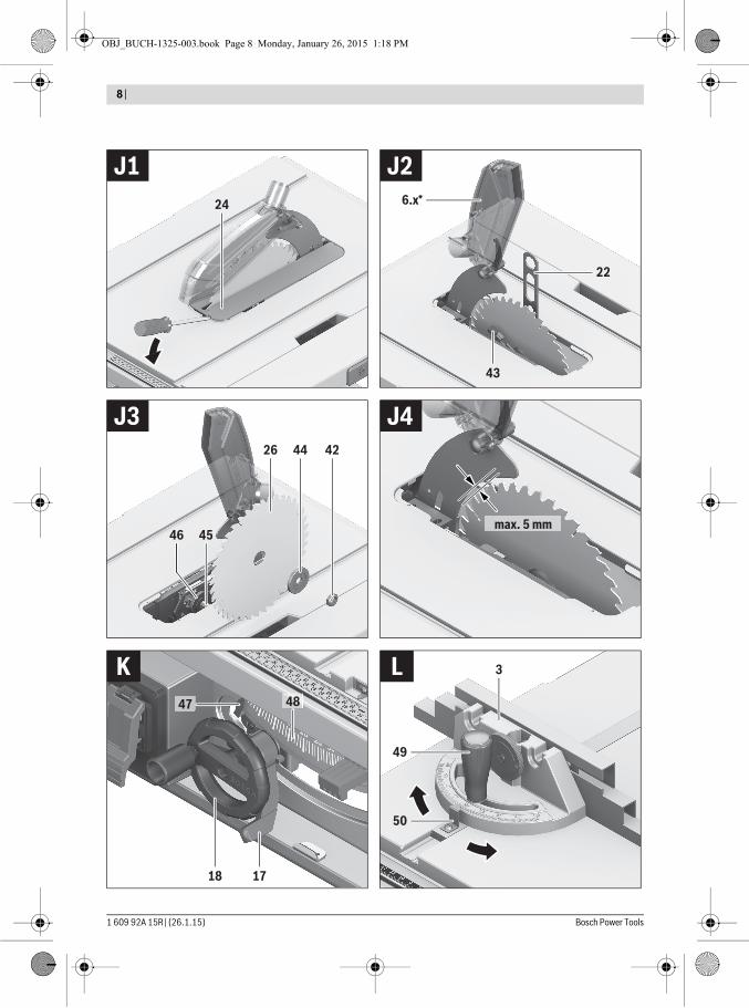
Removing the Saw Blade– Using a screwdriver, raise the insert plate 24 at the front
and remove it from the tool basin.– Turn crank 19 clockwise to the stop, so that the saw blade
26 is in the highest possible position above the saw table.– Tilt the blade guard 6.x toward the rear to the stop.– Turn the clamping nut 42 with the ring spanner 22
(23 mm) and at the same time, pull the spindle lock lever 43 until it engages.
– Keep the spindle lock lever pulled and unscrew the clamp-ing nut turning in anticlockwise direction.
– Remove the clamping flange 44.– Remove the saw blade 26.
Mounting the Saw BladeIf required, clean all parts to be mounted prior to assembly.– Place the new saw blade onto the supporting flange 46 of
the tool spindle 45.Note: Do not use saw blades that are too small. The clearance between saw blade and riving knife must not exceed 5 mm (max.).
OBJ_BUCH-1325-003.book Page 32 Monday, January 26, 2015 1:18 PM
English | 33
Bosch Power Tools 1 609 92A 15R | (26.1.15)
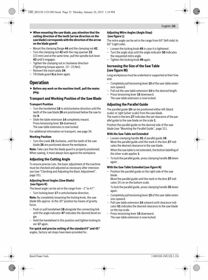
When mounting the saw blade, pay attention that the cutting direction of the teeth (arrow direction on the saw blade) corresponds with the direction of the arrow on the blade guard!
– Mount the clamping flange 44 and the clamping nut 42.– Turn the clamping nut 42 with the ring spanner 22
(23 mm) and at the same time, pull the spindle lock lever 43 until it engages.
– Tighten the clamping nut in clockwise direction (Tightening torque approx. 15–23 Nm).
– Reinsert the insert plate 24.– Tilt blade guard 6.x down again.
Operation Before any work on the machine itself, pull the mains
plug.
Transport and Working Position of the Saw BladeTransport Position– Turn the handwheel 18 in anticlockwise direction until the
teeth of the saw blade 26 are positioned below the saw ta-ble 9.
– Slide the table extension 14 completely inward.Press tensioning lever 15 downward.The saw-table extension is now locked.
For additional information on transport, see page 36.
Working Position– Turn the crank 19 clockwise, until the teeth of the saw
blade 26 are positioned above the workpiece.Note: Take care that the blade guard is properly positioned. When sawing, it must always face against the workpiece.
Adjusting the Cutting AngleTo ensure precise cuts, the basic adjustment of the machine must be checked and adjusted as necessary after intensive use (see “Checking and Adjusting the Basic Adjustment”, page 35).
Adjusting Bevel Angles (Saw Blade) (see figure K)The bevel angle can be set in the range from –2° to 47°.– Turn locking lever 17 in anticlockwise direction.Note: By completely loosening the locking knob, the saw blade tilts approx. to the 30° position by means of gravity force.– Push or pull handwheel 18 alongside the connecting link
until the angle indicator 47 indicates the desired bevel an-gle.
– Hold the handwheel in this position and tighten locking le-ver 17 again.
For quick and precise setting of the standard 0° and 45° angles, factory-set stops have been provided for.
Adjusting Mitre Angles (Angle Stop) (see figure L)The mitre angle can be set in the range from 60° (left side) to 60° (right side).– Loosen the locking knob 49 in case it is tightened.– Turn the angle stop until the angle indicator 50 indicates
the requested mitre angle.– Tighten the locking knob 49 again.
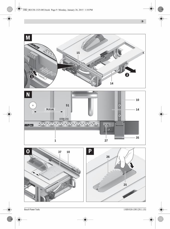
Increasing the Size of the Saw Table (see figure M)Long workpieces must be underlaid or supported at their free end.– Completely pull tensioning lever 15 of the saw-table exten-
sion upward.– Pull out the saw-table extension 14 to the desired length.– Press tensioning lever 15 downward.
The saw-table extension is now locked.
Adjusting the Parallel GuideThe parallel guide 10 can be positioned either left (black scale) or right (silver scale) from the saw blade.The mark in the lens 27 indicates the set clearance of the par-allel guide to the saw blade on the scale 1.Position the parallel guide on the desired side of the saw blade (see “Mounting the Parallel Guide”, page 31).
With the Saw Table not Extended– Loosen clamping handle 35 of parallel guide 10.
Move the parallel guide until the mark in the lens 27 indi-cates the desired clearance to the saw blade.When the saw table is not extended, the bottom labelling of the silver scale applies 1.
– To lock the parallel guide, press clamping handle 35 down again.
With the Saw Table Extended (see figure N)– Position the parallel guide on the right side of the saw
blade.Move the parallel guide until the mark in the lens 27 indi-cates 26 cm on the bottom scale.To lock the parallel guide, press clamping handle 35 down again.
– Completely pull tensioning lever 15 of the saw-table exten-sion upward.
– Pull saw-table extension 14 outward until clearance indi-cator 51 indicates the desired clearance to the saw blade on the top scale.
– Press tensioning lever 15 downward.The saw-table extension is now locked.
OBJ_BUCH-1325-003.book Page 33 Monday, January 26, 2015 1:18 PM
34 | English
1 609 92A 15R | (26.1.15) Bosch Power Tools
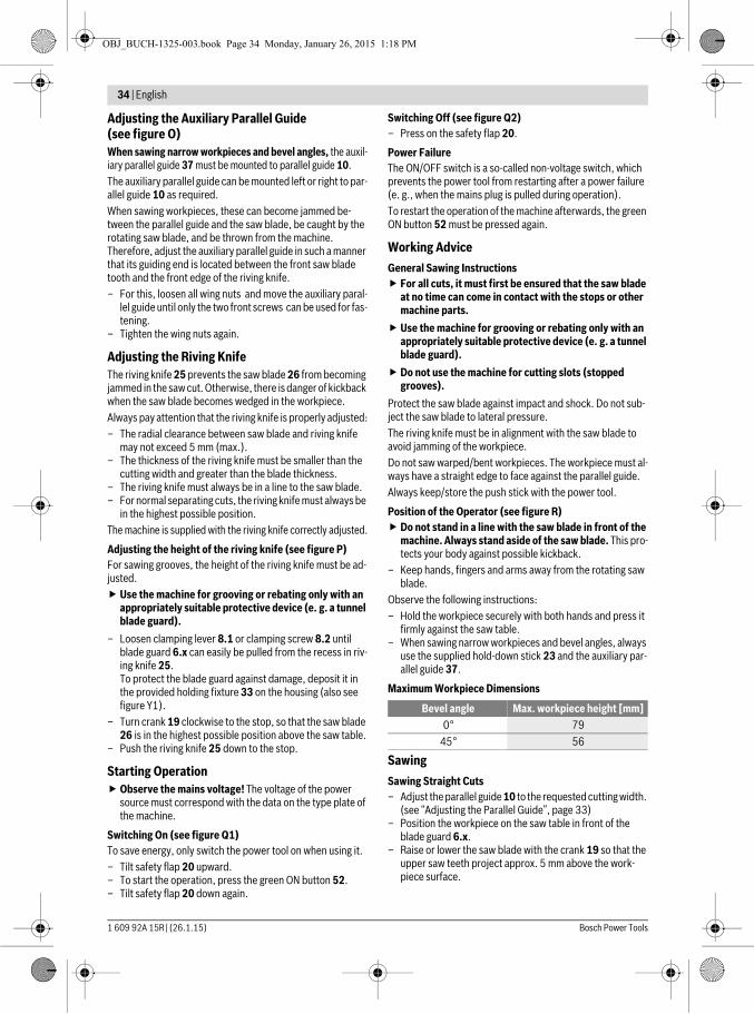
Adjusting the Auxiliary Parallel Guide (see figure O)When sawing narrow workpieces and bevel angles, the auxil-iary parallel guide 37 must be mounted to parallel guide 10.The auxiliary parallel guide can be mounted left or right to par-allel guide 10 as required.When sawing workpieces, these can become jammed be-tween the parallel guide and the saw blade, be caught by the rotating saw blade, and be thrown from the machine.Therefore, adjust the auxiliary parallel guide in such a manner that its guiding end is located between the front saw blade tooth and the front edge of the riving knife.– For this, loosen all wing nuts and move the auxiliary paral-
lel guide until only the two front screws can be used for fas-tening.
– Tighten the wing nuts again.
Adjusting the Riving KnifeThe riving knife 25 prevents the saw blade 26 from becoming jammed in the saw cut. Otherwise, there is danger of kickback when the saw blade becomes wedged in the workpiece.Always pay attention that the riving knife is properly adjusted:– The radial clearance between saw blade and riving knife
may not exceed 5 mm (max.).– The thickness of the riving knife must be smaller than the
cutting width and greater than the blade thickness.– The riving knife must always be in a line to the saw blade.– For normal separating cuts, the riving knife must always be
in the highest possible position.The machine is supplied with the riving knife correctly adjusted.
Adjusting the height of the riving knife (see figure P)For sawing grooves, the height of the riving knife must be ad-justed. Use the machine for grooving or rebating only with an
appropriately suitable protective device (e. g. a tunnel blade guard).
– Loosen clamping lever 8.1 or clamping screw 8.2 until blade guard 6.x can easily be pulled from the recess in riv-ing knife 25.To protect the blade guard against damage, deposit it in the provided holding fixture 33 on the housing (also see figure Y1).
– Turn crank 19 clockwise to the stop, so that the saw blade 26 is in the highest possible position above the saw table.
– Push the riving knife 25 down to the stop.
Starting Operation Observe the mains voltage! The voltage of the power
source must correspond with the data on the type plate of the machine.
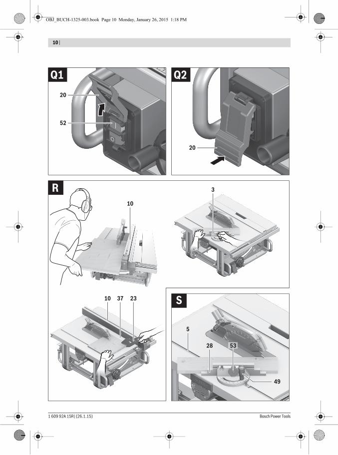
Switching On (see figure Q1)To save energy, only switch the power tool on when using it.– Tilt safety flap 20 upward.– To start the operation, press the green ON button 52.– Tilt safety flap 20 down again.
Switching Off (see figure Q2)– Press on the safety flap 20.
Power FailureThe ON/OFF switch is a so-called non-voltage switch, which prevents the power tool from restarting after a power failure (e. g., when the mains plug is pulled during operation).To restart the operation of the machine afterwards, the green ON button 52 must be pressed again.
Working AdviceGeneral Sawing Instructions For all cuts, it must first be ensured that the saw blade
at no time can come in contact with the stops or other machine parts.
Use the machine for grooving or rebating only with an appropriately suitable protective device (e. g. a tunnel blade guard).
Do not use the machine for cutting slots (stopped grooves).
Protect the saw blade against impact and shock. Do not sub-ject the saw blade to lateral pressure.The riving knife must be in alignment with the saw blade to avoid jamming of the workpiece.Do not saw warped/bent workpieces. The workpiece must al-ways have a straight edge to face against the parallel guide.Always keep/store the push stick with the power tool.
Position of the Operator (see figure R) Do not stand in a line with the saw blade in front of the
machine. Always stand aside of the saw blade. This pro-tects your body against possible kickback.
– Keep hands, fingers and arms away from the rotating saw blade.
Observe the following instructions:– Hold the workpiece securely with both hands and press it
firmly against the saw table.– When sawing narrow workpieces and bevel angles, always
use the supplied hold-down stick 23 and the auxiliary par-allel guide 37.
Maximum Workpiece Dimensions
SawingSawing Straight Cuts– Adjust the parallel guide 10 to the requested cutting width.
(see “Adjusting the Parallel Guide”, page 33)– Position the workpiece on the saw table in front of the
blade guard 6.x.– Raise or lower the saw blade with the crank 19 so that the
upper saw teeth project approx. 5 mm above the work-piece surface.
Bevel angle Max. workpiece height [mm]0° 79
45° 56
OBJ_BUCH-1325-003.book Page 34 Monday, January 26, 2015 1:18 PM
English | 35
Bosch Power Tools 1 609 92A 15R | (26.1.15)
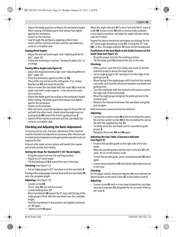
– Adjust the blade guard according to the workpiece height.When sawing, the blade guard must always face lightly against the workpiece.
– Switch on the machine.– Saw through the workpiece applying uniform feed.– Switch off the machine and wait until the saw blade has
come to a complete stop.
Sawing Bevel Angles– Adjust the desired bevel angle. (see “Adjusting Bevel An-
gles”, page 33)– Follow the worksteps in section “Sawing Straight Cuts” ac-
cordingly.
Sawing Mitre Angles (see figure S)– Adjust the requested mitre angle. (see “Adjusting Mitre An-
gles”, page 33)– Place the workpiece against profile rail 28.
The profile may not be on the cutting line. If so, loosen knurled nut 53 and move the profile.
– Raise or lower the saw blade with the crank 19 so that the upper saw teeth project approx. 5 mm above the work-piece surface.
– Adjust the blade guard according to the workpiece height.When sawing, the blade guard must always face lightly against the workpiece.
– Switch on the machine.– With one hand, press the workpiece against the profile rail
and with the other hand, slowly move the angle stop via locking knob 49 toward the front in guide groove 5.
– Switch off the machine and wait until the saw blade has come to a complete stop.
Checking and Adjusting the Basic AdjustmentTo ensure precise cuts, the basic adjustment of the machine must be checked and adjusted as necessary after intensive use.A certain level of experience and appropriate specialty tools are required for this.A Bosch after-sales service station will handle this mainte-nance task quickly and reliably.
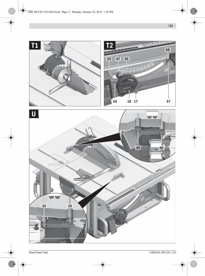
Setting the Stops for Standard 0°/ 45 ° Bevel Angles– Bring the power tool into the working position.– Adjust to a 0° bevel angle.– Tilt the blade guard 6.x toward the rear to the stop.Checking: (see figure T1)– Set an angle gauge to 90° and place it on the saw table 9.The leg of the angle gauge must be flush with the saw blade 26 over the complete length.Adjusting: (see figure T2)– Loosen screw 54.
The 0° stop 55 can now be moved.– Loosen locking lever 17.– Move handwheel 18 toward the 0° stop until the leg of the
angle gauge is flush with the saw blade over the complete length.
– Hold the handwheel in this position and tighten locking le-ver 17 again.
– Tighten screw 54 again.
When the angle indicator 47 is not in line with the 0° mark of scale 48, loosen screw 56 with a commercially available cross-head screwdriver and align the angle indicator along-side the 0° mark.Repeat the above mentioned worksteps accordingly for the 45° bevel angle (loosening screw 57; moving the 45° stop 58). In this, the angle indicator 47 must not be misadjusted.Parallelism of the Saw Blade to the Guide Grooves of the Angle Stop (see figure U)– Bring the power tool into the working position.– Tilt the blade guard 6.x toward the rear to the stop.Checking:– With a pencil, mark the first visible saw tooth on the left
side that projects above the insert plate.– Set an angle gauge to 90° and place it on the edge of the
guide groove 5. – Move the leg of the angle gauge until it touches the marked
saw tooth, and read the clearance between saw blade and guide groove.
– Turn the saw blade until the marked tooth projects above the right side of the insert plate.
– Move the angle gauge alongside the guide groove to the marked tooth.
– Measure the clearance between the saw blade and guide groove again.
Both clearances measured must be identical.Adjusting:– Loosen hex socket screws 59 at the front below the saw ta-
ble and hex socket screws 60 at the rear below the saw ta-ble with the supplied hex key 21.
– Carefully move the saw blade until it is parallel to guide groove 5.
– Retighten all screws 59 and 60 again.
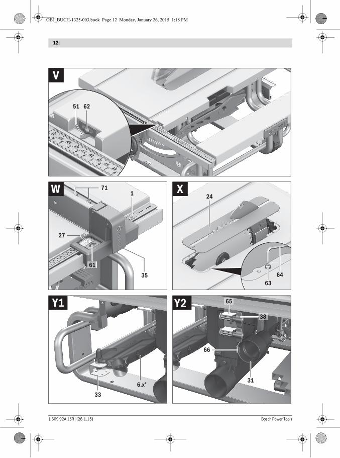
Adjusting the Saw Table’s Clearance Indicator (see figure V)– Position the parallel guide on the right side of the saw
blade.Move the parallel guide until the mark in the lens 27 indi-cates 26 cm on the bottom scale.To lock the parallel guide, press clamping handle 35 down again.
– Loosen tensioning lever 15 and pull the table extension out to the stop.
Checking:On the upper scale 1, clearance indicator 51 must indicate the identical value as the mark in lens 27 on the bottom scale 1.Adjusting:– Loosen screw 61 with a cross-head screwdriver and align
clearance indicator 51 alongside the 26 cm mark of the up-per scale 1.
OBJ_BUCH-1325-003.book Page 35 Monday, January 26, 2015 1:18 PM
36 | English
1 609 92A 15R | (26.1.15) Bosch Power Tools
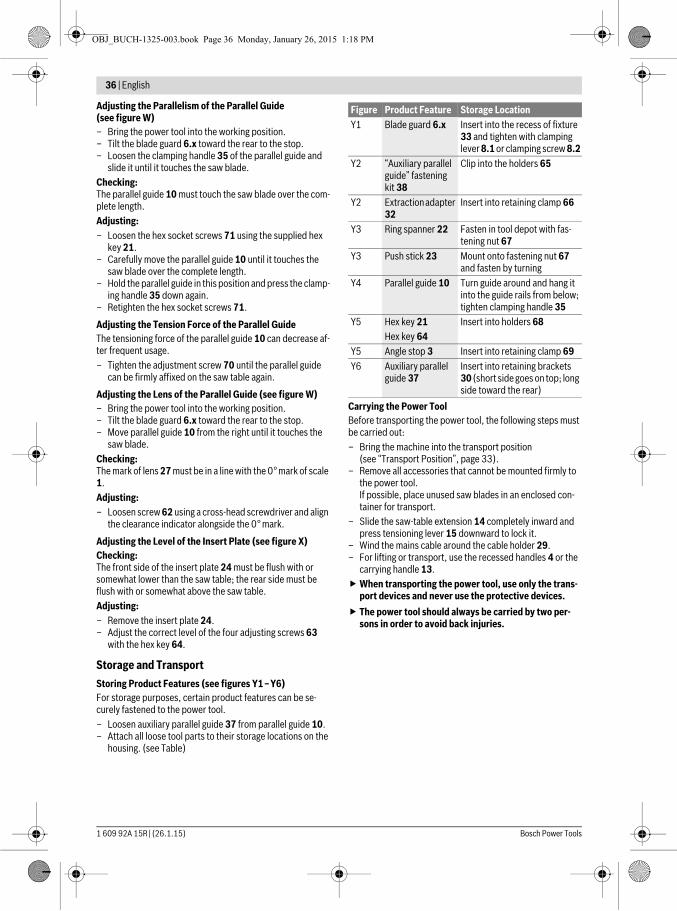
Adjusting the Parallelism of the Parallel Guide (see figure W)– Bring the power tool into the working position.– Tilt the blade guard 6.x toward the rear to the stop.– Loosen the clamping handle 35 of the parallel guide and
slide it until it touches the saw blade.Checking:The parallel guide 10 must touch the saw blade over the com-plete length.Adjusting:– Loosen the hex socket screws 71 using the supplied hex
key 21.– Carefully move the parallel guide 10 until it touches the
saw blade over the complete length. – Hold the parallel guide in this position and press the clamp-
ing handle 35 down again.– Retighten the hex socket screws 71.
Adjusting the Tension Force of the Parallel GuideThe tensioning force of the parallel guide 10 can decrease af-ter frequent usage.– Tighten the adjustment screw 70 until the parallel guide
can be firmly affixed on the saw table again.
Adjusting the Lens of the Parallel Guide (see figure W)– Bring the power tool into the working position.– Tilt the blade guard 6.x toward the rear to the stop.– Move parallel guide 10 from the right until it touches the
saw blade.Checking:The mark of lens 27 must be in a line with the 0° mark of scale 1.Adjusting:– Loosen screw 62 using a cross-head screwdriver and align
the clearance indicator alongside the 0° mark.
Adjusting the Level of the Insert Plate (see figure X)Checking:The front side of the insert plate 24 must be flush with or somewhat lower than the saw table; the rear side must be flush with or somewhat above the saw table.Adjusting:– Remove the insert plate 24.– Adjust the correct level of the four adjusting screws 63
with the hex key 64.
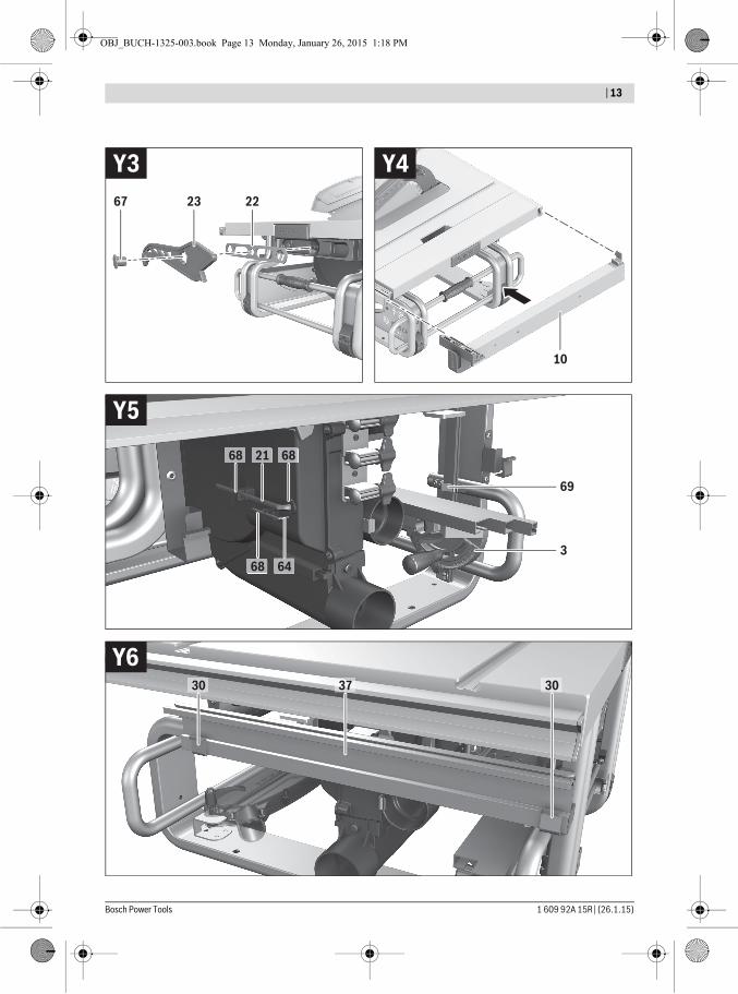
Storage and TransportStoring Product Features (see figures Y1–Y6)For storage purposes, certain product features can be se-curely fastened to the power tool.– Loosen auxiliary parallel guide 37 from parallel guide 10.– Attach all loose tool parts to their storage locations on the
housing. (see Table)
Carrying the Power ToolBefore transporting the power tool, the following steps must be carried out:– Bring the machine into the transport position
(see “Transport Position”, page 33).– Remove all accessories that cannot be mounted firmly to
the power tool.If possible, place unused saw blades in an enclosed con-tainer for transport.
– Slide the saw-table extension 14 completely inward and press tensioning lever 15 downward to lock it.
– Wind the mains cable around the cable holder 29.– For lifting or transport, use the recessed handles 4 or the
carrying handle 13.When transporting the power tool, use only the trans-
port devices and never use the protective devices. The power tool should always be carried by two per-
sons in order to avoid back injuries.
Figure Product Feature Storage LocationY1 Blade guard 6.x Insert into the recess of fixture
33 and tighten with clamping lever 8.1 or clamping screw 8.2
Y2 “Auxiliary parallel guide” fastening kit 38
Clip into the holders 65
Y2 Extraction adapter 32
Insert into retaining clamp 66
Y3 Ring spanner 22 Fasten in tool depot with fas-tening nut 67
Y3 Push stick 23 Mount onto fastening nut 67 and fasten by turning
Y4 Parallel guide 10 Turn guide around and hang it into the guide rails from below; tighten clamping handle 35
Y5 Hex key 21Hex key 64
Insert into holders 68
Y5 Angle stop 3 Insert into retaining clamp 69Y6 Auxiliary parallel
guide 37Insert into retaining brackets 30 (short side goes on top; long side toward the rear)
OBJ_BUCH-1325-003.book Page 36 Monday, January 26, 2015 1:18 PM
English | 37
Bosch Power Tools 1 609 92A 15R | (26.1.15)
Maintenance and ServiceMaintenance and Cleaning Before any work on the machine itself, pull the mains
plug.If the replacement of the supply cord is necessary, this has to be done by Bosch or an authorized Bosch service agent in or-der to avoid a safety hazard.
Cleaning– For safe and proper working, always keep the power tool
and its ventilation slots clean.– Remove dust and chips after each working procedure by
blowing out with compressed air or with a brush.
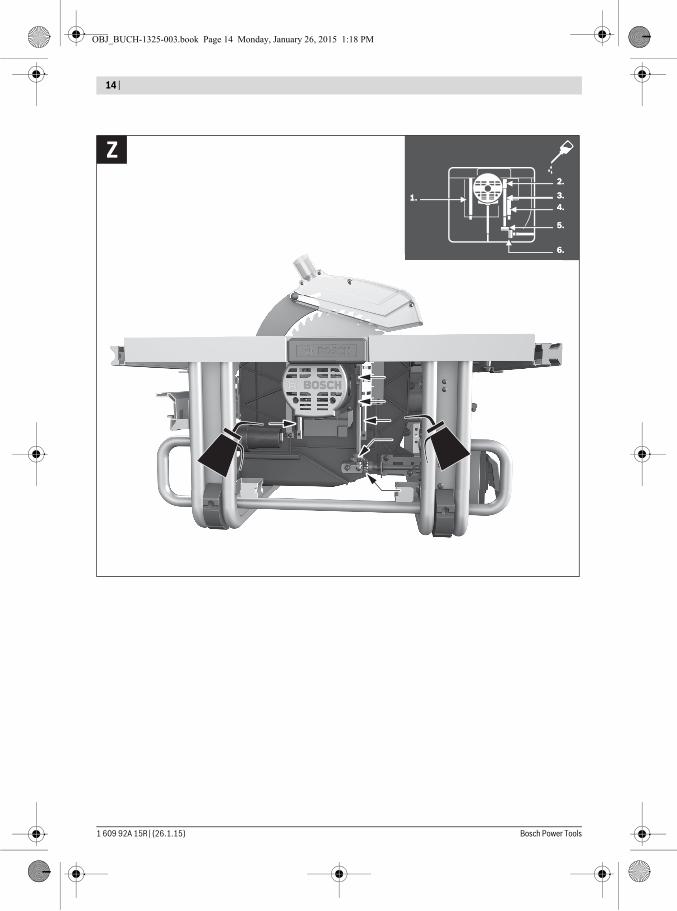
Power Tool LubricationLubricants:SAE 10/SAE 20 engine oil
– If required, lubricate the power tool at the indicated loca-tions. (see figure Z)
An authorized Bosch after-sales service agent will carry out this work quickly and reliably.Observe all applicable environmental regulations when disposing of old grease and solvents.Measures for Noise ReductionMeasures on behalf of the manufacturer:– Soft starting– Delivery of the machine with a saw blade developed partic-
ularly for noise reductionMeasures on behalf of the user:– Low-vibration assembly on a firm working surface– Use of saw blades with noise-reducing functions– Regular cleaning of saw blade and power tool
Accessories
After-sales Service and Application ServiceIn all correspondence and spare parts order, please always in-clude the 10-digit article number given on the type plate of the machine.Our after-sales service responds to your questions concern-ing maintenance and repair of your product as well as spare parts. Exploded views and information on spare parts can al-so be found under:www.bosch-pt.comBosch’s application service team will gladly answer questions concerning our products and their accessories.
Great BritainRobert Bosch Ltd. (B.S.C.)P.O. Box 98Broadwater ParkNorth Orbital RoadDenhamUxbridgeUB 9 5HJAt www.bosch-pt.co.uk you can order spare parts or arrange the collection of a product in need of servicing or repair. Tel. Service: (0344) 7360109E-Mail: [email protected]
IrelandOrigo Ltd.Unit 23 Magna DriveMagna Business ParkCity WestDublin 24Tel. Service: (01) 4666700Fax: (01) 4666888
Australia, New Zealand and Pacific IslandsRobert Bosch Australia Pty. Ltd.Power ToolsLocked Bag 66Clayton South VIC 3169Customer Contact CenterInside Australia:Phone: (01300) 307044Fax: (01300) 307045Inside New Zealand:Phone: (0800) 543353Fax: (0800) 428570Outside AU and NZ:Phone: +61 3 95415555www.bosch.com.au
Republic of South AfricaCustomer serviceHotline: (011) 6519600Gauteng – BSC Service Centre35 Roper Street, New CentreJohannesburgTel.: (011) 4939375Fax: (011) 4930126E-Mail: [email protected]
Article numberDust bag 2 605 411 205Y-adapter TSVH 3 2 610 015 513Angle stop 2 610 015 507Push stick 2 610 015 022Saw stand GTA 60 W 0 601 B12 000Saw stand GTA 600 0 601 B22 001Saw blades for wood and plate materials, panels and strips/mouldingsSaw blade 254 x 30 mm, 40 teeth 2 608 640 443Saw blade 254 x 30 mm, 60 teeth 2 608 640 444
OBJ_BUCH-1325-003.book Page 37 Monday, January 26, 2015 1:18 PM
38 | English
1 609 92A 15R | (26.1.15) Bosch Power Tools
KZN – BSC Service CentreUnit E, Almar Centre143 Crompton StreetPinetownTel.: (031) 7012120Fax: (031) 7012446E-Mail: [email protected] Cape – BSC Service CentreDemocracy Way, Prosperity ParkMilnertonTel.: (021) 5512577Fax: (021) 5513223E-Mail: [email protected] HeadquartersMidrand, GautengTel.: (011) 6519600Fax: (011) 6519880E-Mail: [email protected]
DisposalThe machine, accessories and packaging should be sorted for environmental-friendly recycling.Do not dispose of power tools into household waste!Only for EC countries:
According to the European Directive 2012/19/EU for Waste Electrical and Elec-tronic Equipment and its implementation into national right, power tools that are no longer usable must be collected separately and disposed of in an environmentally cor-rect manner.
Subject to change without notice.
OBJ_BUCH-1325-003.book Page 38 Monday, January 26, 2015 1:18 PM