Fiber Connectors
4
W H I T E P A P E R Choosing the right connector APC vs. UPC
-
Upload
nsshekhawat -
Category
Documents
-
view
237 -
download
0
Transcript of Fiber Connectors
7/31/2019 Fiber Connectors
http://slidepdf.com/reader/full/fiber-connectors 1/4
W H I T
E P A P E R
Choosing the right connector
APC vs. UPC
7/31/2019 Fiber Connectors
http://slidepdf.com/reader/full/fiber-connectors 2/4
Page 2
Choosing the right connector
1LC is a registered trademark of OFS.
The choice between angle-polished connectors (APC) and ultra-polished connectors (UPC) can make a significant impacton how a particular network will perform. There are several considerations to make, including the network design orpurpose and the types of services that will be transported over the fiber. This paper will compare and contrast these twocategories of connectors, highlighting their differences in terms of physical appearance, insertion loss and return losscharacteristics, as well as their overall performance in particular applications.
Passive Optical Network (PON) infrastructures deployed in fiber-to-the-premises (FTTP) networks require numerous fiberconnections to achieve the distribution of services to multiple homes. Although splicing has its place in these systems,use of reliable APC connectors provides numerous advantages in terms of overall network flexibility, testing andtroubleshooting.
Historically, UPC connectors have been the top performers, particularly with regard to insertion loss. For that reason,they are considered the legacy connector and have been deployed in many networks to handle digitally-transmittedinformation. However, due to the improved manufacturing techniques being used today, APC connectors are now on parwith UPC connectors in terms of insertion loss.
There are many other benefits provided through the use of APC connectors, and each should be carefully consideredduring the network design process, particularly, within the FTTX network architecture, where numerous fiber connectionsare required to achieve the distribution of multiple services (triple and quadruple play) to multiple customers.
Physical attributes
The generally accepted color code for connector bodies and/or boots is beige for multimode fiber, blue for singlemodefiber, and green for APC connectors. UPC connectors are easily identifiable by their blue color on the connector boot.Both are available in SC (most common), LC®1, FC and E2000 style connectors.
For both polishing types the ferrule surface has a convex shape to guarantee the physical contact between the ferrules ofthe two mated connectors.
The major physical difference between APC and UPC connectors is the endface geometry. The APC ferrule endface radiusis polished at an 8° angle while UPC connectors are polished at a 0° angle. The significance of this 8° angle becomesapparent when addressing return loss issues, which will be discussed later in this paper.
Standards
Today, the SC connector type is a standard in both inside plant and outside plant applications. Telcordia® GR-326-CORE,
Issue 3 Generic Requirements for Singlemode Optical Connectors and Jumper Assemblies is the guiding document forfiber optic standards. ADC KRONE’s optical performance specifications fall well within these guidelines and arelisted below:
SC UPC Connector SpecifcationsInsertion Loss: 0.2 dB max.
(1310 and 1550 nm) 0.09 dB typicalReturn Loss: 57 dB min.
(1310 and 1550 nm)
SC APC ConnectorsInsertion Loss: 0.35 dB max.
(1310 and 1550 nm) 0.15 dB typicalReturn Loss: 65 dB min.
(1310 and 1550 nm)
Endace Angle: 8˚ ± 0.5
7/31/2019 Fiber Connectors
http://slidepdf.com/reader/full/fiber-connectors 3/4
Page 3
Insertion Loss
The performance difference between APC and UPC connectors begins with insertion loss (IL). Insertion loss is defined as themeasurement for the amount of optical power lost through a mated connector pair. The connector insertion loss can beused with the cable length loss to determine the allowable loss budget for an installed link. The formula for insertion loss is:
In the past, low insertion loss using APC connectors was difficult to achieve due to air gaps in the apex offsets whichcaused substantial loss. However, due to improved connector designs and manufacturing processes, insertion lossdifferences between APC and UPC connectors have diminished. Most advertised typical insertion loss characteristicsrange from 0,14 dB to 0,18 dB for both connector types. ADC KRONE’s typical insertion loss values range from 0.09 dBto 0.15 dB for both connector types.
Today, the factors that relate to insertion loss are the same for both connector types. All four of these factors areidentical for today´s APC and UPC connectors.
• Outsidediameter(OD)ofthefiber
• Concentricityofthefibercore
• Insidediameter(ID)oftheferrule
• Concentricityoftheferrule’sID
Return Loss
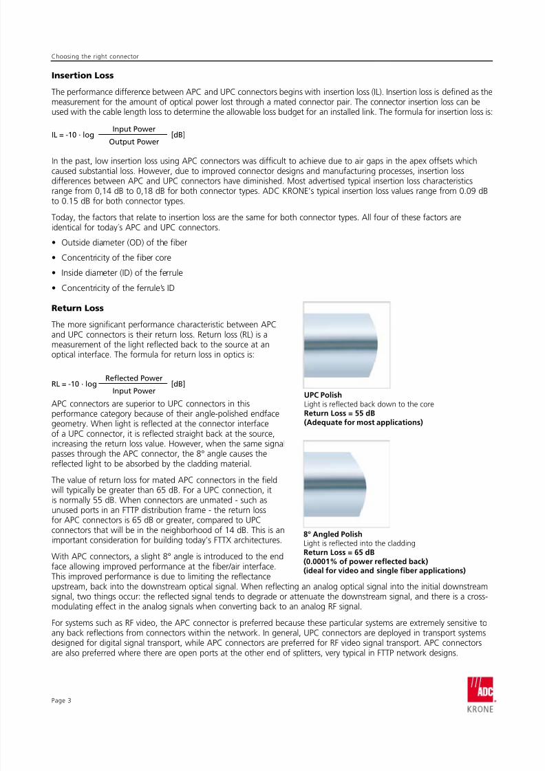
The more significant performance characteristic between APCand UPC connectors is their return loss. Return loss (RL) is ameasurement of the light reflected back to the source at anoptical interface. The formula for return loss in optics is:
APC connectors are superior to UPC connectors in thisperformance category because of their angle-polished endfacegeometry. When light is reflected at the connector interfaceof a UPC connector, it is reflected straight back at the source,increasing the return loss value. However, when the same signalpasses through the APC connector, the 8° angle causes thereflected light to be absorbed by the cladding material.
The value of return loss for mated APC connectors in the fieldwill typically be greater than 65 dB. For a UPC connection, itis normally 55 dB. When connectors are unmated - such asunused ports in an FTTP distribution frame - the return lossfor APC connectors is 65 dB or greater, compared to UPCconnectors that will be in the neighborhood of 14 dB. This is an
important consideration for building today’s FTTX architectures.
With APC connectors, a slight 8° angle is introduced to the endface allowing improved performance at the fiber/air interface.This improved performance is due to limiting the reflectanceupstream, back into the downstream optical signal. When reflecting an analog optical signal into the initial downstreamsignal, two things occur: the reflected signal tends to degrade or attenuate the downstream signal, and there is a cross-modulating effect in the analog signals when converting back to an analog RF signal.
For systems such as RF video, the APC connector is preferred because these particular systems are extremely sensitive toany back reflections from connectors within the network. In general, UPC connectors are deployed in transport systemsdesigned for digital signal transport, while APC connectors are preferred for RF video signal transport. APC connectorsare also preferred where there are open ports at the other end of splitters, very typical in FTTP network designs.
UPC Polish
Light is reflected back down to the coreReturn Loss = 55 dB(Adequate or most applications)
8° Angled PolishLight is reflected into the claddingReturn Loss = 65 dB(0.0001% o power relected back)(ideal or video and single iber applications)
Choosing the right connector
IL = -10 . logInput Power
Output Power [dB]
RL = -10 . logRefected Power
Input Power[dB]
7/31/2019 Fiber Connectors
http://slidepdf.com/reader/full/fiber-connectors 4/4
W H I T E P A P E R
Web Site: www.adckrone.com
EMEA Oice: ADCGmbH,Beeskowdamm,3-11,14167Berlin,Germany•Phone:+4930 8453-1818Fax:+49308453-1703.ForalistingofallADCKRONE’sglobalsalesofficelocations,pleaserefertoourwebsite.
UK Oice: ADC Communications (UK) Ltd., Runnings Road, Kingsditch Trading Estate, Cheltenham,GloucestershireGL519NQ,UnitedKingdom•Phone:+44(0)1242264400Fax:+44(0)[email protected]
Specifications published here are current as of the date of publication of this document. Because we are continuouslyimproving our products, ADC KRONE reserves the right to change specifications without prior notice. At any time,you may verify product specifications by contacting ADC GmbH headquarters in Berlin. ADC Telecommunications, Inc.views its patent portfolio as an important corporate asset and vigorously enforces its patents.
105662BE Feb 09 Revision © 2009 ADC Telecommunications, Inc. All Rights Reserved
Endface Geometry Issues
In order to demonstrate the recent strides that have made APC the preferred connector in outside
plant and passive optical networks, a brief discussion of APC endface geometry is important.
During the manufacturing process, it is critical to control the endface geometry parameters: apexoffset, radius of curvature, and fiber height. Preventing ferrule rotation that can change the apex offsetof an APC connector to an unacceptable standard has been a critical manufacturing issue. Changingand inconsistent interfaces, which allow ferrule rotation about the ferrule axis, have the potentialto create air gaps between the mated pair fiber cores. This results in significantly degraded, if notinterrupted, transmission performance.
ADC KRONE has developed an anti-rotational feature on its APC connectors that corrects ferrulerotation. This feature forces the ferrule back into its original position if the ferrule is rotated eitherclockwise or counter-clockwise within the housing. This guarantees apex measurements will bemaintained throughout the life of the connector, regardless of how many matings and unmatings areperformed.
Conclusion
The manufacturing techniques used today have greatly improved the performance for both the UPCand APC connectors. When considering your unique network design, the APC connector is a good all-around connector choice, although the decision will ultimately come down to return loss requirements.In the end, ADC KRONE can help you examine all the considerations and issues regarding whichconnector - the APC or UPC - will best perform in your unique deployment scenario.