
Elevator Manual - Revit Content...Revit® Content Copyright 2010 -2011 by Aplo Limited, All Rights...
18
Revit Content ® Copyright 2010 -2011 by Aplo Limited, All Rights reserved RFA2220 Elevator ELEVATOR MANUAL
Transcript of Elevator Manual - Revit Content...Revit® Content Copyright 2010 -2011 by Aplo Limited, All Rights...
Revit Content®
Copyright 2010 -2011 by Aplo Limited, All Rights reserved
RFA2220Elevator
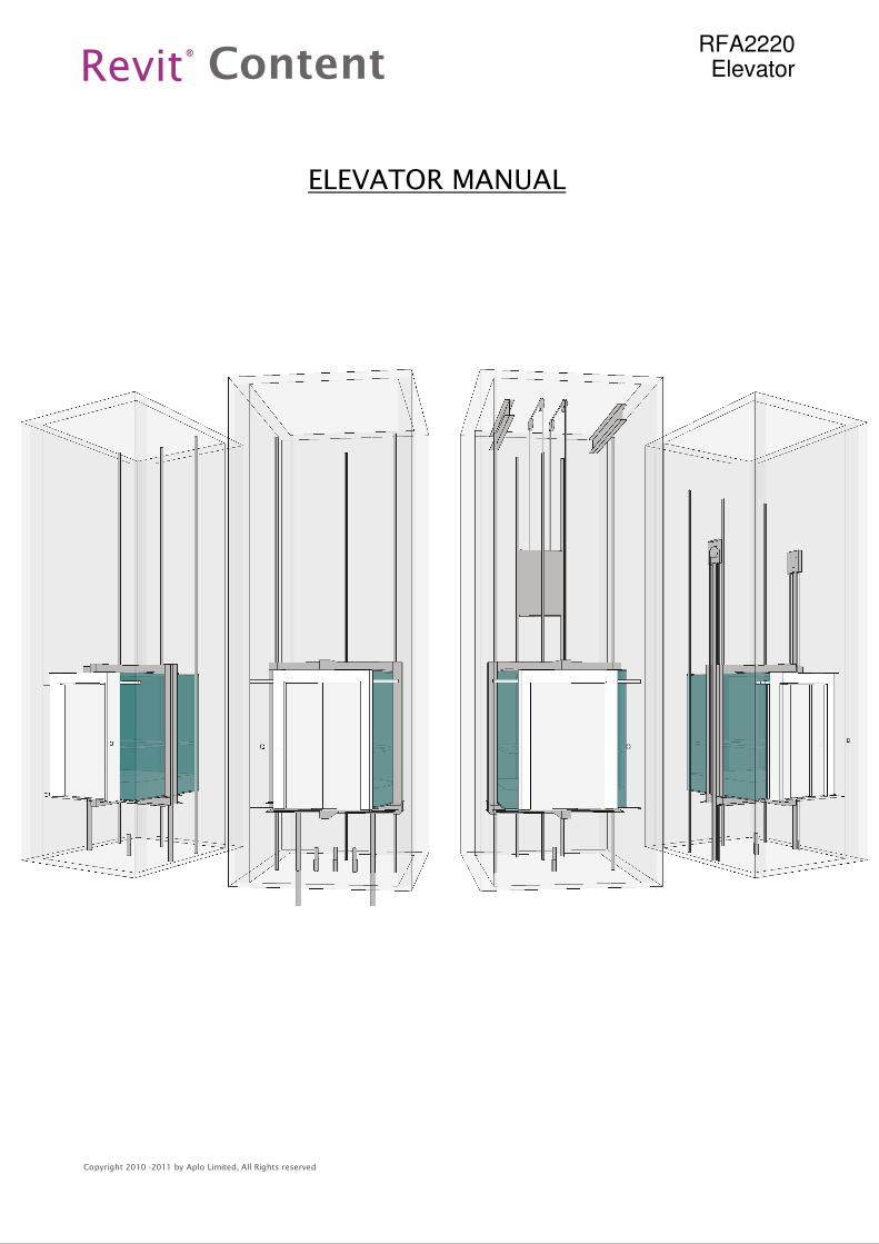
ELEVATOR MANUAL
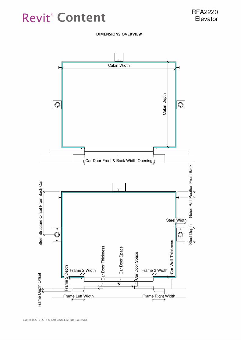
Car Door Front & Back Width Opening
Cabin Width
Cabin
Depth
Frame Left Width Frame Right Width
Fra
me D
epth
Off
set
Ste
el S
tructu
re O
ffset
Fro
m B
ack C
ar
Guid
e R
ail
Positio
n F
rom
Back
Steel Width
Ste
el D
epth
Car
Door
Thic
kness
Car
Door
Space
Frame 2 WidthFrame 2 Width
Car
Wall
Thic
kness
Fra
me 2
Depth
Car
Door
Space
Revit Content®
Copyright 2010 -2011 by Aplo Limited, All Rights reserved
RFA2220Elevator
DIMENSIONS OVERVIEW
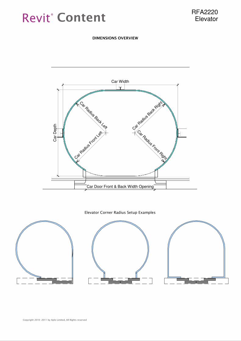
Car R
adius Back Left Car
Rad
ius Bac
k Right
Car
Rad
ius Fro
nt L
eft C
ar Radius Front R
ight
Car Width
Car
Depth
Car Door Front & Back Width Opening
Revit Content®
Copyright 2010 -2011 by Aplo Limited, All Rights reserved
RFA2220Elevator
DIMENSIONS OVERVIEW
Elevator Corner Radius Setup Examples
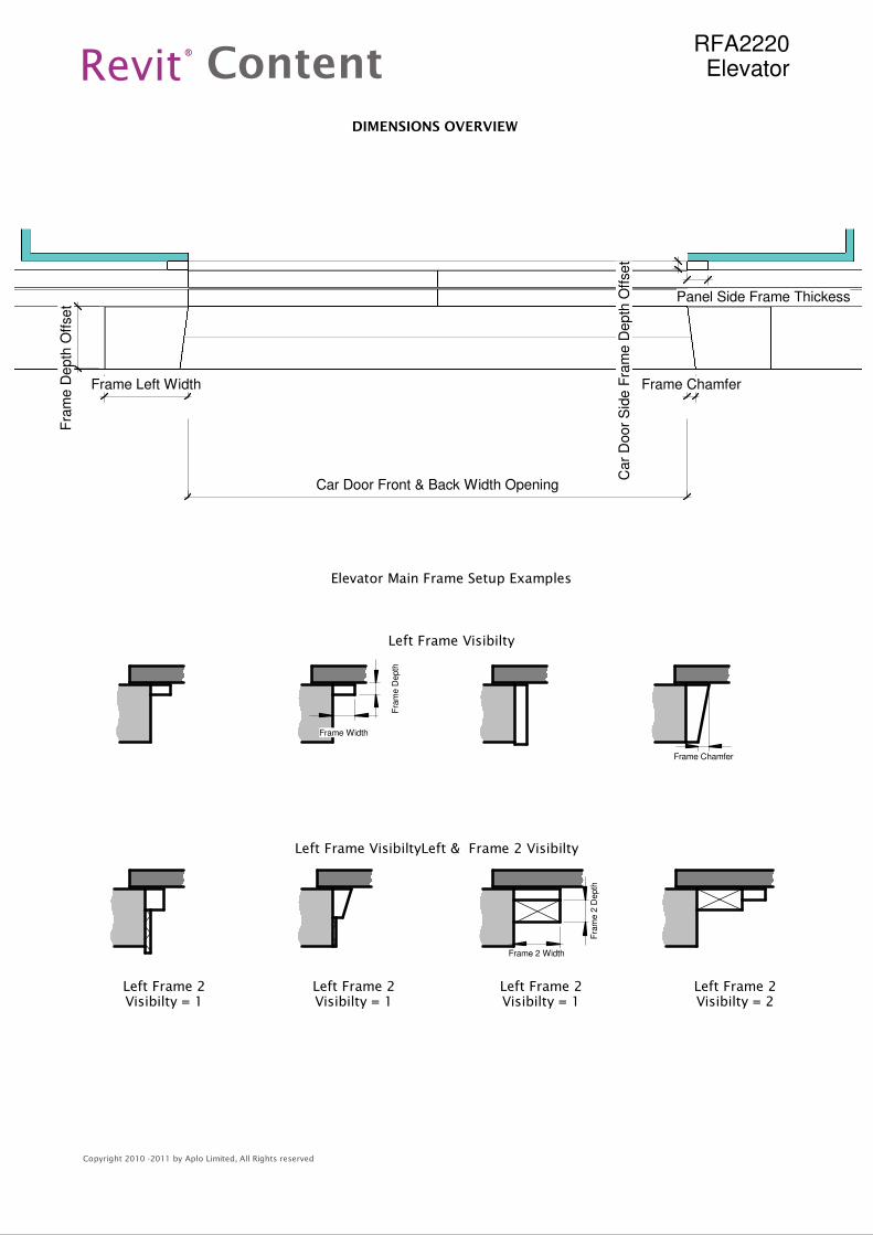
Car Door Front & Back Width Opening
Car
Door
Sid
e F
ram
e D
epth
Off
set
Panel Side Frame Thickess
Frame Left Width
Fra
me D
epth
Off
set
Frame Chamfer
Frame 2 Width
Fra
me 2
Depth
Frame Chamfer
Fra
me D
epth
Frame Width
Revit Content®
Copyright 2010 -2011 by Aplo Limited, All Rights reserved
RFA2220Elevator
DIMENSIONS OVERVIEW
Elevator Main Frame Setup Examples
Left Frame Visibilty
Left Frame VisibiltyLeft & Frame 2 Visibilty
Left Frame 2Visibilty = 1
Left Frame 2Visibilty = 1
Left Frame 2Visibilty = 2
Left Frame 2Visibilty = 1
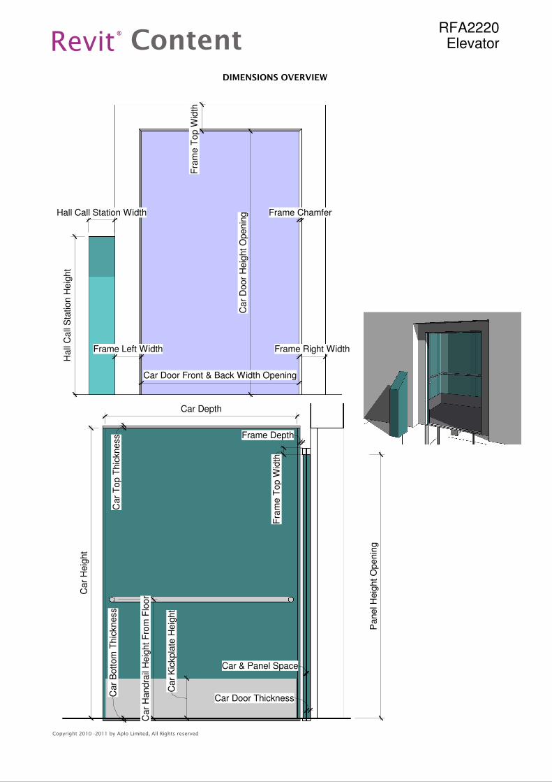
Car
Door
Heig
ht O
penin
g
Car Door Front & Back Width Opening
Frame Right WidthFrame Left Width
Fra
me T
op W
idth
Hall
Call
Sta
tion H
eig
ht
Hall Call Station Width Frame Chamfer
Panel H
eig
ht O
penin
g
Car Depth
Car
Heig
ht
Fra
me T
op W
idth
Car Door Thickness
Car & Panel Space
Car
Kic
kpla
te H
eig
ht
Car
Handra
il H
eig
ht F
rom
Flo
or
Car
Top T
hic
kness
Car
Bott
om
Thic
kness
Frame Depth
Revit Content®
Copyright 2010 -2011 by Aplo Limited, All Rights reserved
RFA2220Elevator
DIMENSIONS OVERVIEW
Revit Content®
Copyright 2010 -2011 by Aplo Limited, All Rights reserved
RFA2220Elevator
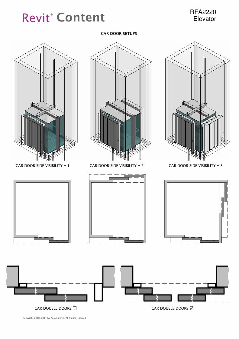
CAR DOOR SETUPS
CAR DOOR SIDE VISIBILITY = 1 CAR DOOR SIDE VISIBILITY = 2 CAR DOOR SIDE VISIBILITY = 3
CAR DOUBLE DOORSCAR DOUBLE DOORS
Revit Content®
Copyright 2010 -2011 by Aplo Limited, All Rights reserved
RFA2220Elevator
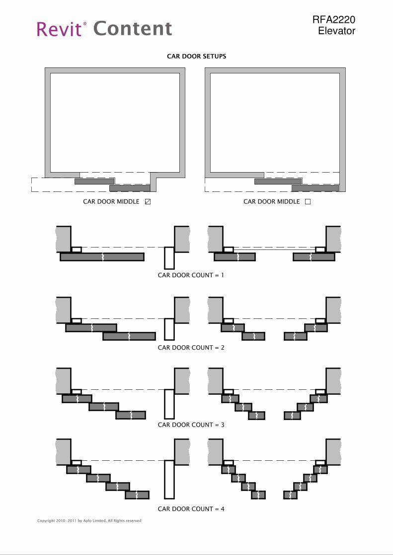
CAR DOOR SETUPS
CAR DOOR COUNT = 1
CAR DOOR COUNT = 2
CAR DOOR COUNT = 3
CAR DOOR COUNT = 4
CAR DOOR MIDDLE CAR DOOR MIDDLE
..
..
..
..
Revit Content®
Copyright 2010 -2011 by Aplo Limited, All Rights reserved
RFA2220Elevator
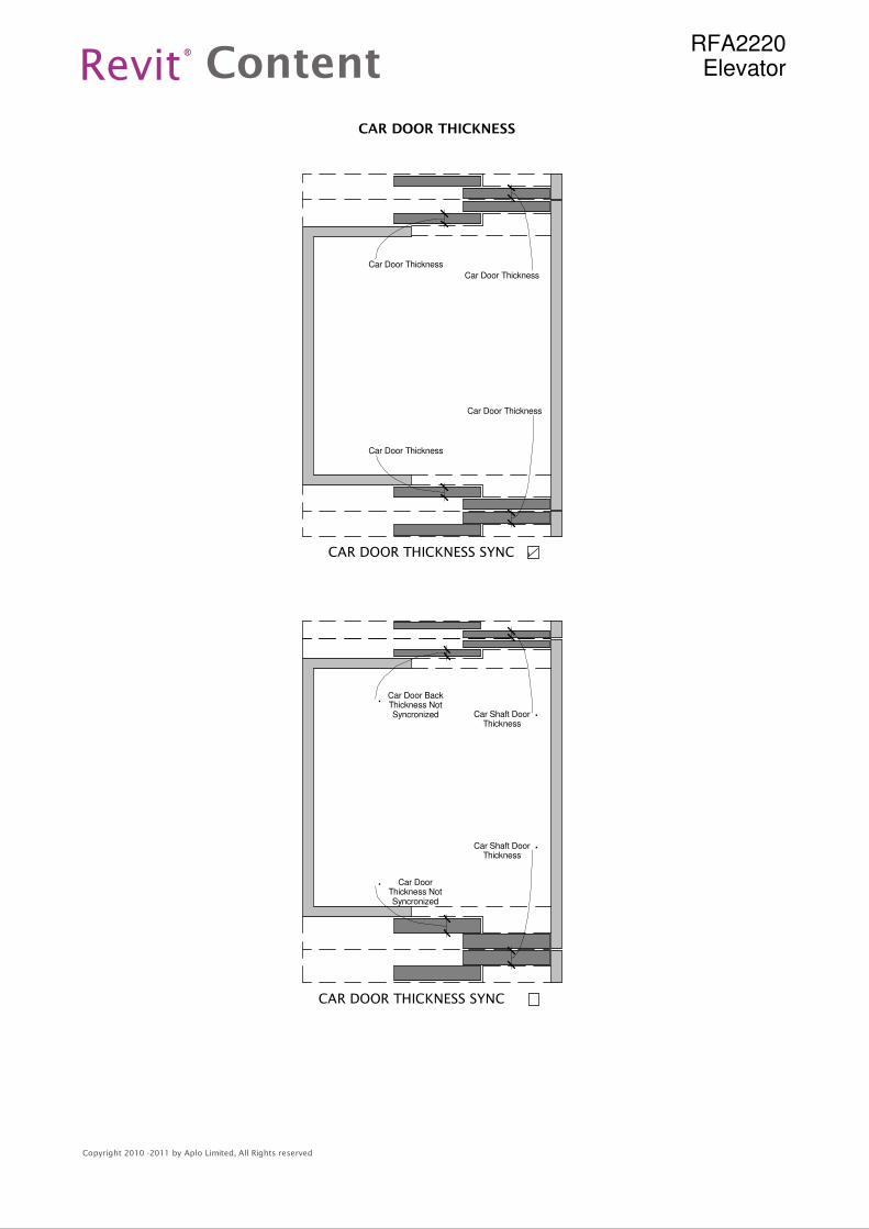
CAR DOOR THICKNESS
CAR DOOR THICKNESS SYNC
CAR DOOR THICKNESS SYNC
Car Door BackThickness NotSyncronized
Car DoorThickness NotSyncronized
Car Shaft DoorThickness
Car Door Thickness
Car Door Thickness
Car Door Thickness
Car Shaft DoorThickness
Car Door Thickness
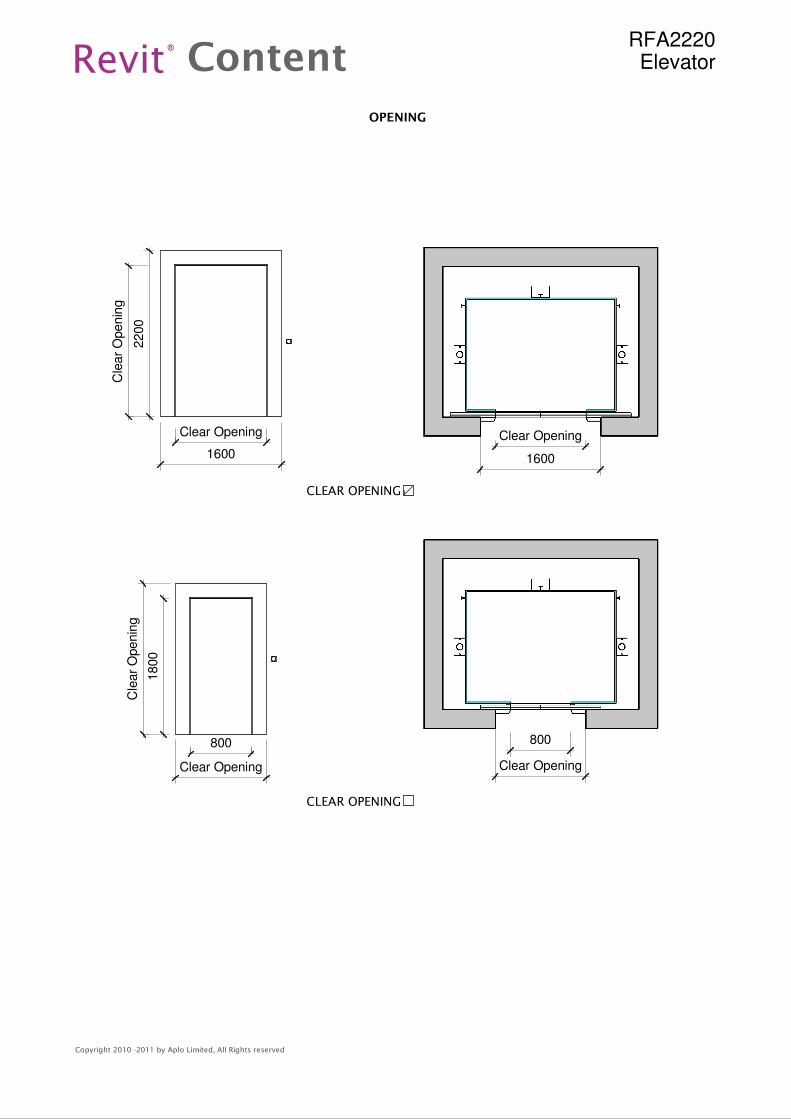
Clear Opening
1600
800
Clear Opening
Clear Opening
1600
Cle
ar
Openin
g
2200
800
Clear Opening
1800
Cle
ar
Openin
g
Revit Content®
Copyright 2010 -2011 by Aplo Limited, All Rights reserved
RFA2220Elevator
OPENING
CLEAR OPENING
CLEAR OPENING
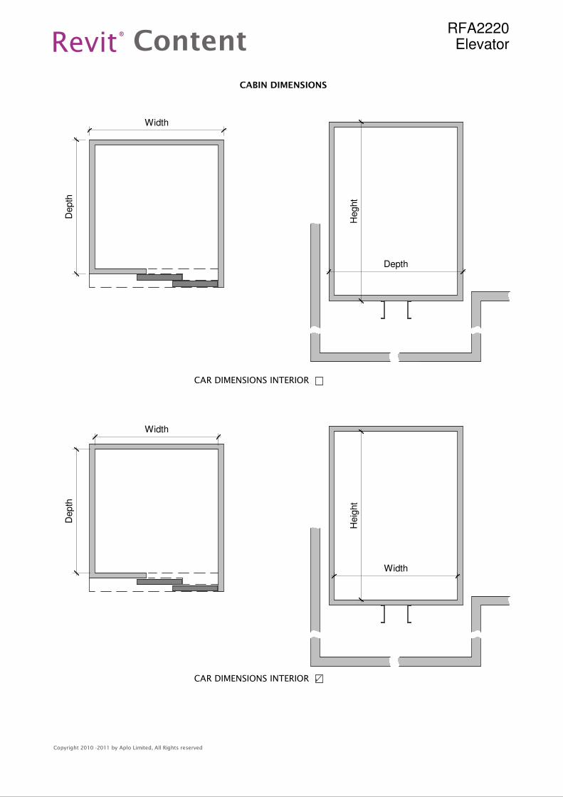
Width
Depth
Width
Depth
Heght
Depth
Heig
ht
Width
Revit Content®
Copyright 2010 -2011 by Aplo Limited, All Rights reserved
RFA2220Elevator
CAR DIMENSIONS INTERIOR
CABIN DIMENSIONS
CAR DIMENSIONS INTERIOR
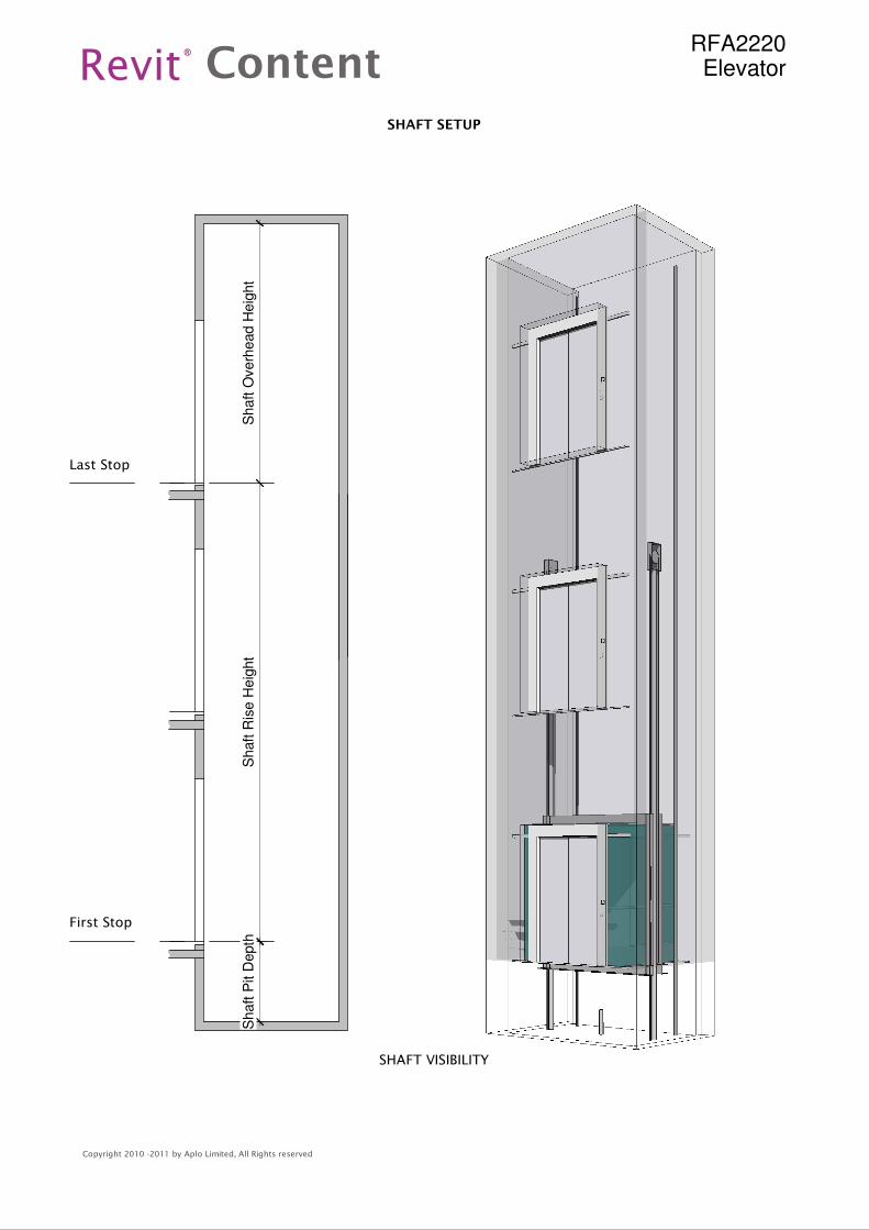
Shaft O
verh
ead H
eig
ht
Shaft
Ris
e H
eig
ht
Shaft P
it D
epth
First Stop
Last Stop
Revit Content®
Copyright 2010 -2011 by Aplo Limited, All Rights reserved
RFA2220Elevator
SHAFT SETUP
SHAFT VISIBILITY
Revit Content®
Copyright 2010 -2011 by Aplo Limited, All Rights reserved
RFA2220Elevator
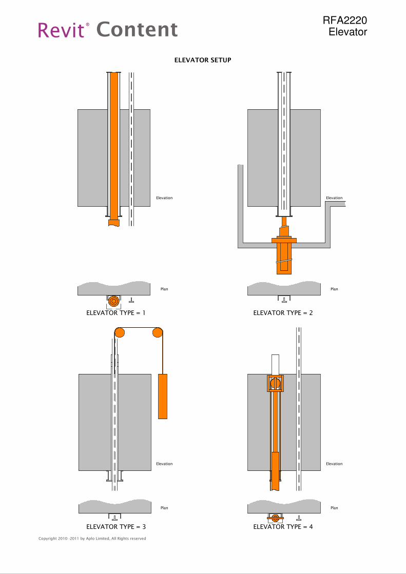
ELEVATOR SETUP
ELEVATOR TYPE = 1 ELEVATOR TYPE = 2
ELEVATOR TYPE = 3 ELEVATOR TYPE = 4
Elevation
Plan
Elevation
Plan
Elevation
Plan
Elevation
Plan
Revit Content®
Copyright 2010 -2011 by Aplo Limited, All Rights reserved
RFA2220Elevator
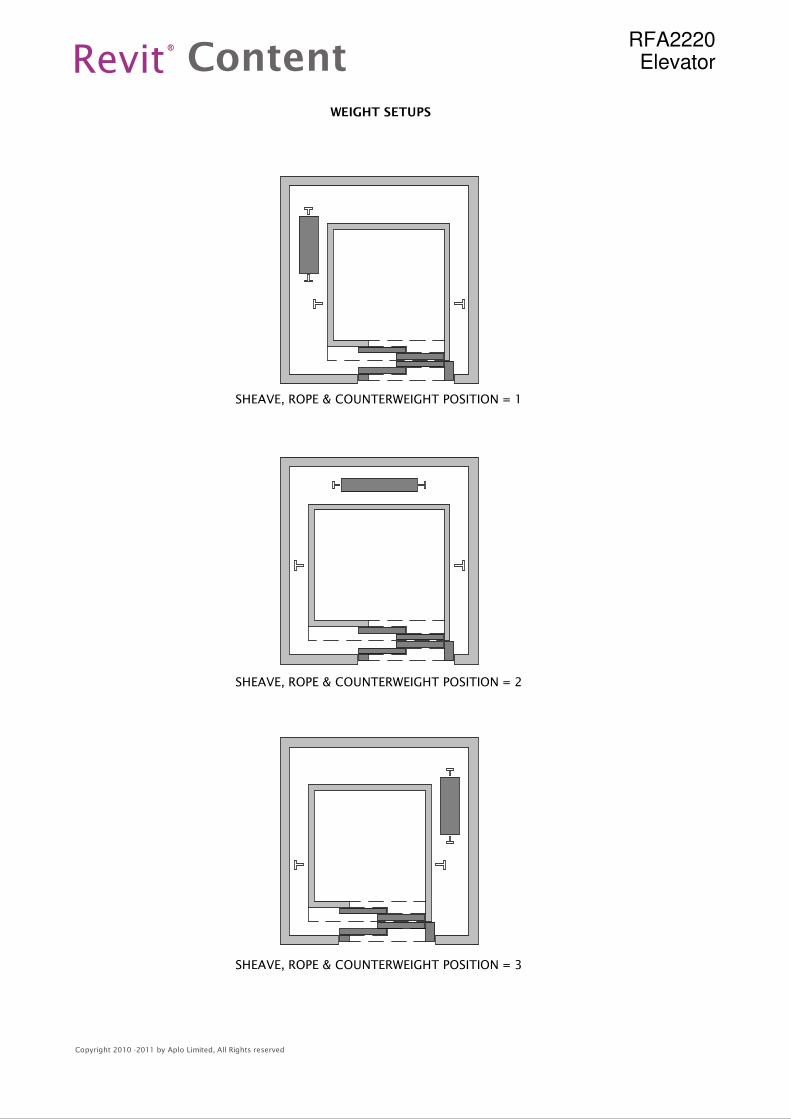
WEIGHT SETUPS
SHEAVE, ROPE & COUNTERWEIGHT POSITION = 1
SHEAVE, ROPE & COUNTERWEIGHT POSITION = 2
SHEAVE, ROPE & COUNTERWEIGHT POSITION = 3
Revit Content®
Copyright 2010 -2011 by Aplo Limited, All Rights reserved
RFA2220Elevator
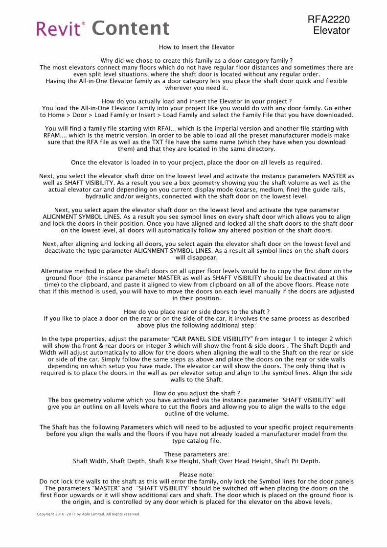
How to Insert the Elevator
Why did we chose to create this family as a door category family ?The most elevators connect many floors which do not have regular floor distances and sometimes there are
even split level situations, where the shaft door is located without any regular order.Having the All-in-One Elevator family as a door category lets you place the shaft door quick and flexible
wherever you need it.
How do you actually load and insert the Elevator in your project ?You load the All-in-One Elevator Family into your project like you would do with any door family. Go eitherto Home > Door > Load Family or Insert > Load Family and select the Family File that you have downloaded.
You will find a family file starting with RFAI... which is the imperial version and another file starting withRFAM.... which is the metric version. In order to be able to load all the preset manufacturer models makesure that the RFA file as well as the TXT file have the same name (which they have when you download
them) and that they are located in the same directory.
Once the elevator is loaded in to your project, place the door on all levels as required.
Next, you select the elevator shaft door on the lowest level and activate the instance parameters MASTER aswell as SHAFT VISIBILITY. As a result you see a box geometry showing you the shaft volume as well as theactual elevator car and depending on you current display mode (coarse, medium, fine) the guide rails,
hydraulic and/or weights, connected with the shaft door on the lowest level.
Next, you select again the elevator shaft door on the lowest level and activate the type parameterALIGNMENT SYMBOL LINES. As a result you see symbol lines on every shaft door which allows you to alignand lock the doors in their position. Once you have aligned and locked all the shaft doors to the shaft door
on the lowest level, all doors will automatically follow any altered position of the shaft doors.
Next, after aligning and locking all doors, you select again the elevator shaft door on the lowest level anddeactivate the type parameter ALIGNMENT SYMBOL LINES. As a result all symbol lines on the shaft doors
will disappear.
Alternative method to place the shaft doors on all upper floor levels would be to copy the first door on theground floor (the instance parameter MASTER as well as SHAFT VISIBILITY should be deactivated at thistime) to the clipboard, and paste it aligned to view from clipboard on all of the above floors. Please note
that if this method is used, you will have to move the doors on each level manually if the doors are adjustedin their position.
How do you place rear or side doors to the shaft ?If you like to place a door on the rear or on the side of the car, it involves the same process as described
above plus the following additional step:
In the type properties, adjust the parameter “CAR PANEL SIDE VISIBILITY” from integer 1 to integer 2 whichwill show the front & rear doors or integer 3 which will show the front & side doors . The Shaft Depth andWidth will adjust automatically to allow for the doors when aligning the wall to the Shaft on the rear or sideor side of the car. Simply follow the same steps as above and place the doors on the rear or side wallsdepending on which setup you have made. The elevator car will show the doors. The only thing that is
required is to place the doors in the wall as per elevator setup and align to the symbol lines. Align the sidewalls to the Shaft.
How do you adjust the shaft ?The box geometry volume which you have activated via the instance parameter “SHAFT VISIBILITY” willgive you an outline on all levels where to cut the floors and allowing you to align the walls to the edge
outline of the volume.
The Shaft has the following Parameters which will need to be adjusted to your specific project requirementsbefore you align the walls and the floors if you have not already loaded a manufacturer model from the
type catalog file.
These parameters are:Shaft Width, Shaft Depth, Shaft Rise Height, Shaft Over Head Height, Shaft Pit Depth.
Please note:Do not lock the walls to the shaft as this will error the family, only lock the Symbol lines for the door panelsThe parameters “MASTER” and “SHAFT VISIBILITY” should be switched off when placing the doors on the
first floor upwards or it will show additional cars and shaft. The door which is placed on the ground floor isthe origin, and is controlled by any door which is placed for the elevator on the above levels.
Revit Content®
Copyright 2010 -2011 by Aplo Limited, All Rights reserved
RFA2220Elevator
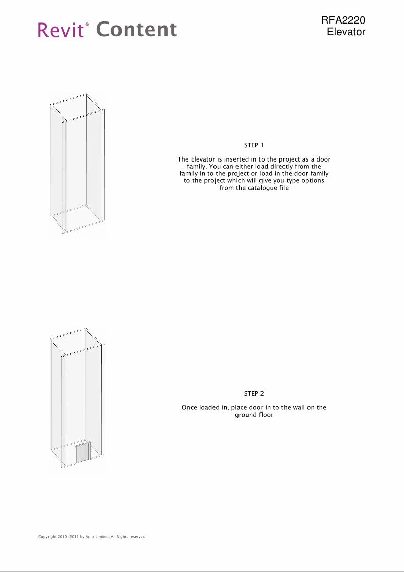
STEP 2
Once loaded in, place door in to the wall on theground floor
STEP 1
The Elevator is inserted in to the project as a doorfamily. You can either load directly from the
family in to the project or load in the door familyto the project which will give you type options
from the catalogue file
Revit Content®
Copyright 2010 -2011 by Aplo Limited, All Rights reserved
RFA2220Elevator
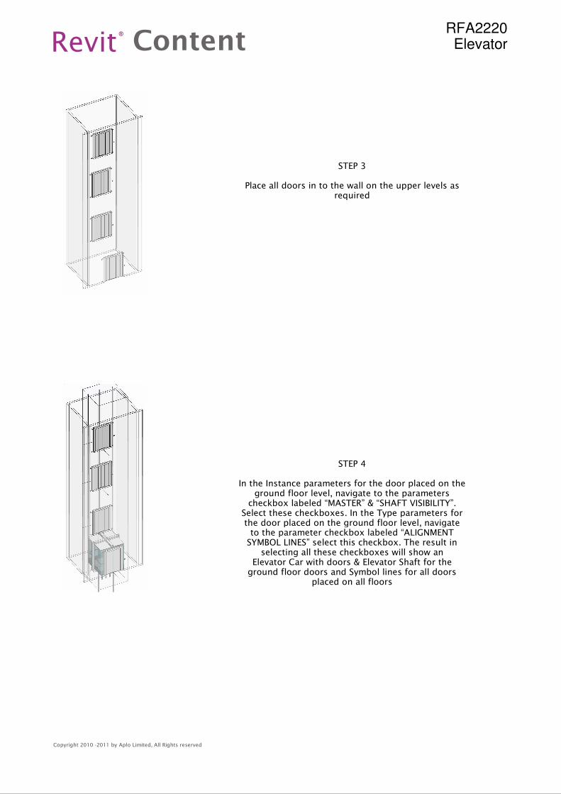
STEP 4
In the Instance parameters for the door placed on theground floor level, navigate to the parameterscheckbox labeled “MASTER” & “SHAFT VISIBILITY”.
Select these checkboxes. In the Type parameters forthe door placed on the ground floor level, navigateto the parameter checkbox labeled “ALIGNMENTSYMBOL LINES” select this checkbox. The result in
selecting all these checkboxes will show anElevator Car with doors & Elevator Shaft for theground floor doors and Symbol lines for all doors
placed on all floors
STEP 3
Place all doors in to the wall on the upper levels asrequired
Revit Content®
Copyright 2010 -2011 by Aplo Limited, All Rights reserved
RFA2220Elevator
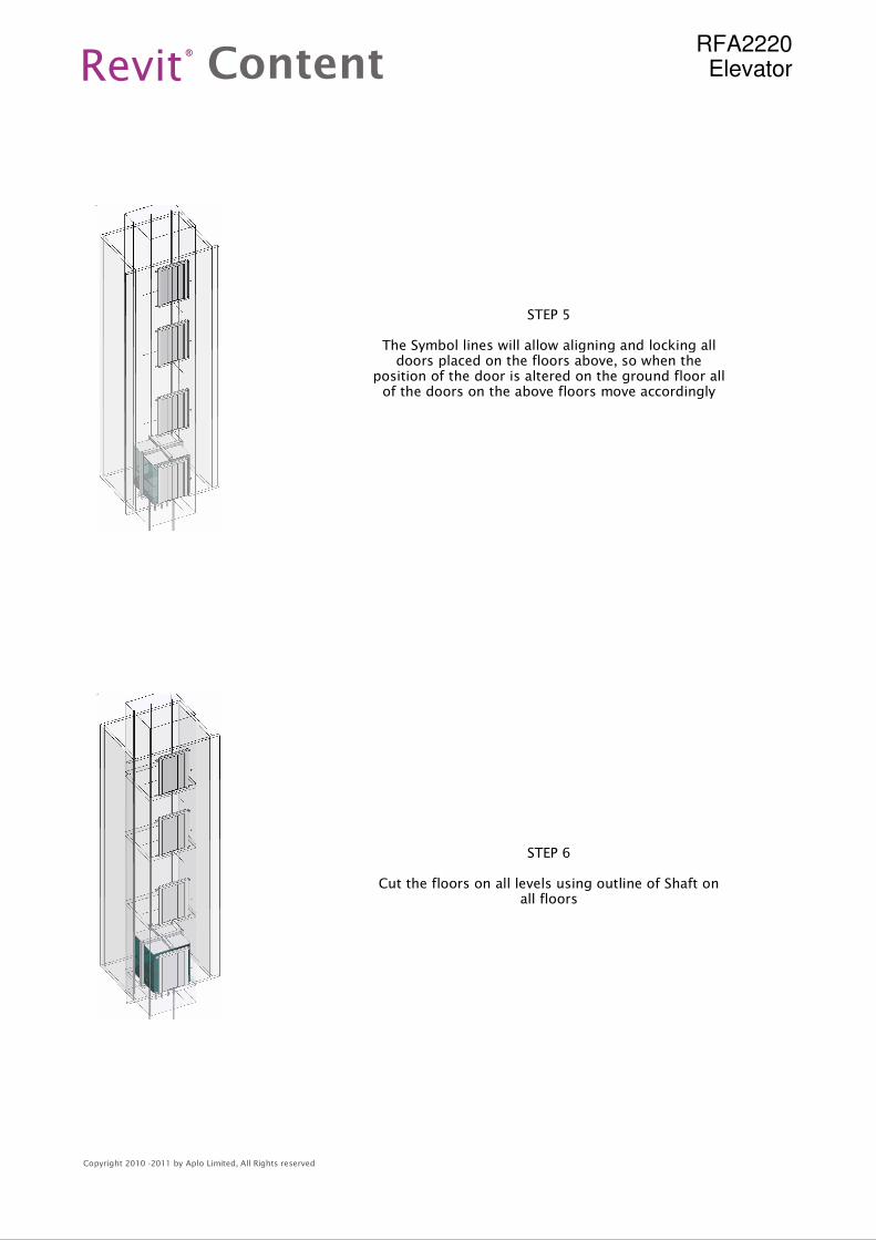
STEP 6
Cut the floors on all levels using outline of Shaft onall floors
STEP 5
The Symbol lines will allow aligning and locking alldoors placed on the floors above, so when the
position of the door is altered on the ground floor allof the doors on the above floors move accordingly
Revit Content®
Copyright 2010 -2011 by Aplo Limited, All Rights reserved
RFA2220Elevator
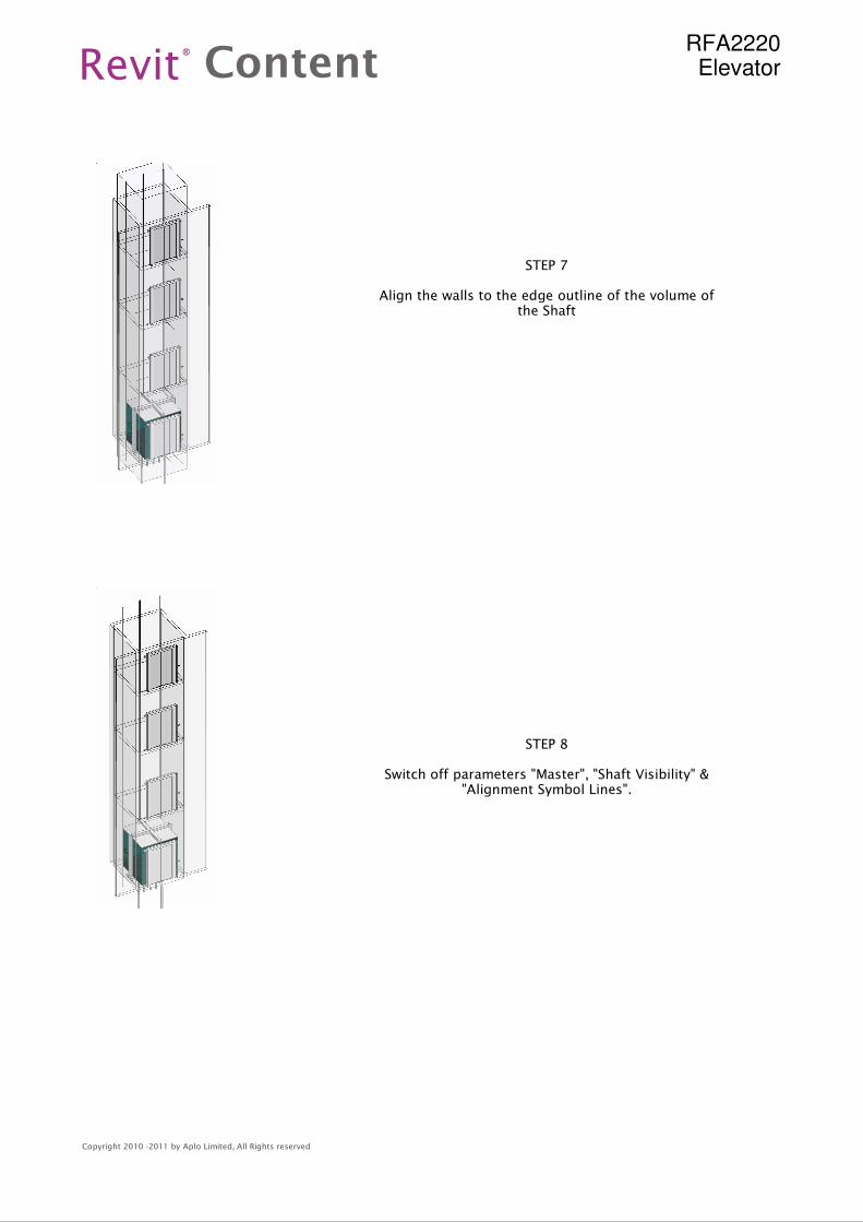
STEP 8
Switch off parameters "Master", "Shaft Visibility" &"Alignment Symbol Lines".
STEP 7
Align the walls to the edge outline of the volume ofthe Shaft