
dudbc.gov.np › uploads › default › files › 02876ad... · E E arth ng qu Volum inee ake B e...
356
E E E E E E a a r r t t h h E E n n g g h h q q u u Volu m m gi i n n e e e e u u a a k k e e B B m meI: S S Gov Min Dep Bui Ear Re Pro e e r r s s ' ' e e R R e es B B u u i i l l S Seismi c c M Ma vernment nistry of partmen ilding Co rthqua covery ogram T T r r a a s s i i s s t ta ld d i i n n g c city an d d ay 2 2 0 0 1 1 1 1 of Nepal Physical nt of Urb onstructi ake Ris y Prepa me for a a i i n n i i n n a a n n t t g g s s d d Desi g g 1 1 l Plannin an Deve ion sk Redu aredne r Nepal n n g g o o D D e e s s g gn Asp ng and W elopmen uction ess l o o n n s s i i g g n n ects Works t and and n n o o f f
Transcript of dudbc.gov.np › uploads › default › files › 02876ad... · E E arth ng qu Volum inee ake B e...
EEEE
EEaarrtthhEEnngghhqquu
VVoolluumm
giinneeeeuuaakkee
BB
mmee II :: SS
GovMinDepBuiEarRePro
eerrss'' ee RReesBBuuiill
SSeeiissmmiicc
MMa
vernment nistry of partmenilding Corthquacoveryogram
TTrraassiissttalddiinngg
cciittyy aanndd
ay 22001111
of Nepal Physicalnt of Urbonstructiake Risy Prepame for
aaiinniinnaanntt ggss
dd DDeessiigg
11
l Planninan Deveion sk Reduaredner Nepal
nngg oo DDeess
ggnn AAsspp
ng and Welopmen
uction ess l
oonn ssiiggnn
eeccttss
Works t and
and
nn ooff
Acknowledgement
Earthquake Risk Reduction and Recovery Preparedness Programme for Nepal (ERRRP Project) with the financial support of Government of Japan and UNDP- Nepal is assigned in carrying out various activities related to Earthquake safety and recovery preparedness in five identified municipalities located in 5 different development region of Nepal. This program has helped to strengthen the institutional and community level capacity to plan and implement earthquake risk reduction and disaster recovery preparedness in the country through capacity building, public education and awareness, retrofitting demonstration and preparation of study reports on building safety against seismic risk. To ensure earthquake resistant construction, appropriate knowledge needs to be disseminated to a broad spectrum of professional engineers and designers. This manual is therefore expected to be useful to designers & engineering professionals in general and to those involved in analysis, design and construction of buildings in particular. Broader use of this training manual will definitely raise earthquake safety awareness and will be useful in achieving highly important objective of the government to reduce urban risks including earthquakes.
I appreciate and acknowledge the efforts of the project officials and professionals' team in preparing this manual. I encourage the users of this manual for providing creative comments and suggestions to further improve the content and context to make this book more user-friendly.
Purna Kadariya Secretary, Ministry of Physical Panning and Works
Preface
Technology in earthquake resistant building construction has advanced tremendously in last years and has demonstrated good practices in reducing impact of earthquakes. There are number of earthquake codes and guidelines aimed towards safe building construction. But many earthquake prone countries are still struggling with appropriate building construction practices. The main reason behind this is the lack of proper knowledge in earthquake resistant building design and construction.
Designers and supervisors play a vital role for the effective implementation of Building Codes. Capacity building of all stakeholders thus is the key factor for earthquake risk reduction. They need to take responsibility for motivating and convincing house owners and constructors to apply earthquake resistant techniques by utilizing their technical knowledge and skill. These trainings should focus more on practical basis. Engineers should learn actual condition of construction sites and elaborate proposal based on actual conditions.
Though earthquake engineering must be introduced in the regular course of civil engineering, this manual is an exercise towards availing standard training curriculum that covers major aspects of seismicity. I hope the contribution of this manual towards achieving the national goal of reduced disaster risk will be considerable and be very much useful in proper implementation of National Building Code of Nepal.
Ashok Nath Uprety Director General Department of Urban Development and Building Construction
Foreword
Nepal is a country that stands at 11th rank in the world with respect to vulnerability to earthquake hazards. In this context UNDP/BCPR (Bureau of Crisis Prevention and Recovery) with the support of Government of Japan initiated an Earthquake Risk Reduction and Recovery Preparedness (ERRRP) program in five high risk South Asian countries: Nepal, Bhutan, Bangladesh, India and Pakistan. ERRRP Project is being implemented by the Ministry of Physical Planning and Works (MPPW) in close coordination with other line ministries and Programme Municipalities. ERRRP project is engaged in carrying out various activities related to Earthquake safe constructions, Earthquake preparedness and recovery planning in five municipalities of Nepal located in different development regions. They are Biratnagar, Hetauda, Pokhara, Birendranagar and Dhangadhi.
The ultimate aim of the project is sustainable earthquake disaster mitigation in Nepal by better training and capacity building of professional engineers in earthquake engineering. As we all know, earthquakes do not kill people but poorly designed or constructed buildings do. A properly designed, detailed and constructed structure can resist an earthquake of high intensity. But in Nepal, due to lack of manpower and technical competence, regulatory agencies are lagging behind to properly enforce seismic design Codes and standards.
The Department of Urban Development and Building construction is the main agency responsible for the implementation of the Building Act. National Building Codes including the NBC 105: Seismic Design of Buildings in Nepal are developed as provisioned by the Act. This manual is therefore expected to be useful for the department in future conduction of training programs on "Structural Analysis and Earthquake Resistant Design of Buildings Using SAP 2000 and Nepal National Building Code" for Municipal and other professional engineers, designers, architects etc.
This manual has been developed by the ERRRP project with professional input from the National Society for Earthquake Technology-Nepal (NSET) and is based on the experiences gained by the project during conduction of similar trainings in its 5 project municipalities. This document is assumed to serve as a standard training curriculum and ready-to-use training material that covers a wide range of seismicity, its design, assessment and will considerably help in implementation of Building Codes.
This manual is being prepared in two separate volumes to ensure easiness of its use. Volume I covers the theoretical aspects of seismicity, earthquake resistant design and assessment and general provisions of National Building Code whereas the Volume II covers its practical aspects including computer based applications.

We are thankful to the project officials and professionals' team including NSET in preparing this manual.
Sagar Krishna Joshi Suresh Prakash Acharya
National Project Manager, ERRRP National Project Director, ERRRP and
Joint Secretary Ministry of Physical Planning and Works
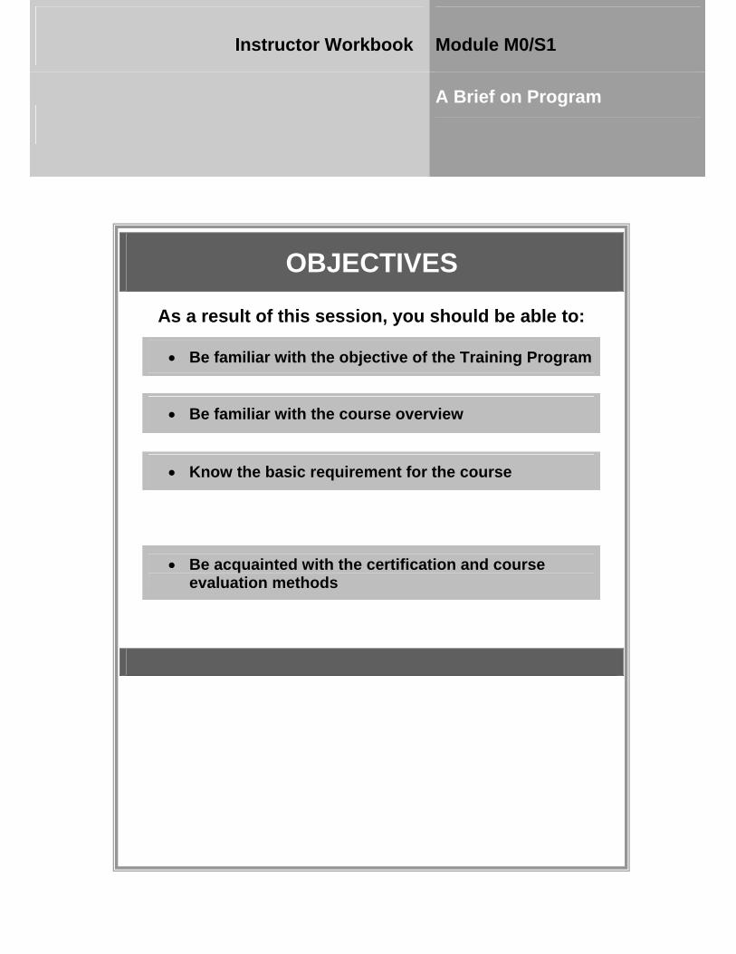
OBJECTIVES
As a result of this session, you should be able to:
• Be familiar with the objective of the Training Program
• Be familiar with the course overview
• Know the basic requirement for the course
• Be acquainted with the certification and course evaluation methods
Instructor Workbook Module M0/S1
A Brief on Program
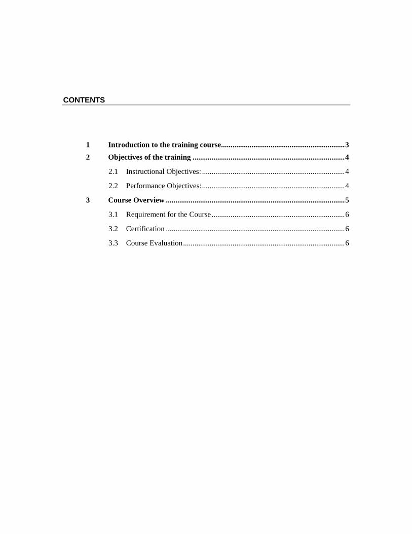
CONTENTS
1 Introduction to the training course ................................................................. 3 2 Objectives of the training ................................................................................ 4
2.1 Instructional Objectives: ........................................................................... 4
2.2 Performance Objectives: ........................................................................... 4
3 Course Overview .............................................................................................. 5
3.1 Requirement for the Course ...................................................................... 6
3.2 Certification .............................................................................................. 6
3.3 Course Evaluation ..................................................................................... 6
M0/S1-3
I n s t r u c t o r W o r k b o o k A Brief on Program Module M0/S1
1 INTRODUCTION TO THE TRAINING COURSE
Nepal is one of the most seismically vulnerable countries in the world which has a history of many earthquakes. We have experienced many earthquakes in our neighboring countries in recent times, some of which have been disastrous in terms of human and property loss such as Bhuj (2001) and Bam (2003) in India, Pakistan (Oct 2005) and China (May 2008). Unfortunately, most casualties during earthquakes are caused not by the earthquake itself, but by the collapse of manmade structures. Earthquakes do not kill people but poorly designed or constructed buildings do. It is true that earthquakes of similar shaking intensity could be more disastrous in developing countries than in developed regions due to lack of knowledge and proper attention to seismic design and quality of building construction. A properly designed, detailed and constructed structure can resist an earthquake of high intensity. Although common people are not aware of many aspects of earthquake disaster and better building practices in seismic zones of the country, the methodology and provisions of Codes are available for reducing the losses due to earthquake.
In Nepal, seismic design and construction is not included in the curriculum of regular course of civil and structural engineering. Due to lack of sufficient knowledge and capabilities both in terms of availability of manpower and technical competence, regulatory agencies like government organizations and municipal bodies are not being able to properly enforce or implement seismic design standards and Codes in direct construction.
To ensure seismic resistant construction, knowledge of earthquake engineering needs to be spread to a broad spectrum of professional engineers and designers, rather than confining to few specialists. Earthquake resistant construction requires seismic considerations at all stages: from architectural planning to structural design to actual construction and the quality control.
It is very urgent to train Engineers, Professional designers, Builders and Structural Engineers to acquaint them about the current practices on earthquake resistant design and construction. Such training programs translate state-of-the-knowledge into better earthquake resistant state-of-the- practice in construction.
This manual is expected to serve as important tool for safety against seismic hazards. The Manual will be useful to designers & engineering professionals in general and to those involved in analysis, design and construction of buildings in particular.
M0/S1-4
I n s t r u c t o r W o r k b o o k A Brief on Program Module M0/S1
2 OBJECTIVES OF THE TRAINING The training is a technical course and the main objective of the program is to provide training to Engineers and Designers about the current practices of relevant Codes and recent trends on earthquake resistant design and construction. The course will cover most of the standard provisions of Codes on earthquake resistant design and construction of Structures. The following documents are prepared to make this training curricular meet the international standard.
• Instructors workbook • Participants' workbook • Lessons Plan • PowerPoint slides
The ultimate aim of the project is sustainable earthquake disaster mitigation in Nepal by better training and capacity building of professional engineers in earthquake engineering.
The objectives of the course are based on instructional and performance objectives as outlined below:
2.1 Instructional Objectives:
At the end of the course, the participants should be able to:
• Understand the seismicity and seismic risk in Nepal
• Understand earthquake resistant design considerations
• Gather scientific know-how in the field of earthquake engineering and the provisions of Codes for construction in seismic areas
• Design reinforced concrete frame building considering earthquake load
• Design load bearing masonry building considering earthquake load
• Identify structural and non-structural mitigation measures in building structure
• Validate the need of Nepal National Building Code and necessity of its implementation
2.2 Performance Objectives:
At the end of the course, the participants will be able to:
o Identify the major flaws in the prevalent practice of earthquake resistant design of buildings.
o Identify the major flaws in the prevalent practice of construction details.
o Make a good judgment in structural performance of buildings in earthquakes - the ability to understand how the structural system will behave, develop workable and
M0/S1-5
I n s t r u c t o r W o r k b o o k A Brief on Program Module M0/S1
constructible details, use appropriate building materials, and tie building elements together so that it will act as a unit to resist seismic forces.
o Build confidence and carry structural analysis and design of earthquake resistant RC frame and Masonry buildings.
o Generate keen interest among the engineering fraternity in the area of Earthquake Resistant Design of Buildings.
o Have a comprehensive strategy for earthquake disaster mitigation with effective implementation of Building Code.
3 COURSE OVERVIEW
The Course is segmented into EIGHT Modules and THIRTY Sessions.
Participants are provided with Participants workbook, PowerPoint slides and reference materials including the course agenda.
Module 1: SEISMICITY AND SEISMIC RISK
This module has FOUR Sessions. These sessions are indicated in the Course Schedule given on this concept note.
Module 2: EARTHQUAKE RESISTANT DESIGN CONSIDERATION
This Module contains FOUR Sessions.
Module 3: EARTHQUAKE RESISTANCE OF BUILDINGS
This Module contains THREE Sessions.
Module 4: EARTHQUAKE RESISTANT DESIGN OF BUILDINGS: RC FRAME BUILDINGS
This Module contains FOUR Sessions.
Module 5: EARTHQUAKE RESISTANT DESIGN OF BUILDINGS: MASONRY BUILDINGS
This Module contains FOUR Sessions.
Module 6: SEISMIC VULNERABILITY ASSESSMENT AND STRUCTURAL MITIGATION
This module has FOUR Sessions. These sessions are indicated in the Course Schedule given on this concept note.
Module 7: NON STRUCTURAL MITIGATION AND PREPAREDNESS
This Module contains TWO Sessions.
Module 8: BUILDING CODE IMPLEMENTATION AND STRATEGY
This Module contains FIVE Sessions.

M0/S1-6
I n s t r u c t o r W o r k b o o k A Brief on Program Module M0/S1
Each module and session spells Learning Objectives which the instructor/s expects as an end result of the session.
The mode of the training will be PowerPoint presentations and computer based exercises. The participants will practice and learn how to analysis and design earthquake resistant buildings using Structural Engineering Software SAP 2000 and ETABS.
Discussions will be carried on input data and output results of the used Software and participants will follow it in real exercise.
3.1 Requirement for the Course
This course is targeted for professional engineers and designers with knowledge in structural analysis and design of buildings. General understanding and use of Structural engineering Software such as SAP 2000 and ETABS is pre-requisite for 3-D modeling and analysis of the building. Groups consisting of about 4 participants will be formed and a computer will be provided for each group during exercise.
3.2 Certification
Participants who attend all the sessions of the course will be awarded the certificate of completion. Absence in any session of the course will result in incompletion of the course.
3.3 Course Evaluation
There will be pre-test and post test for the participants. Further, participants will also evaluate each session in terms of relevance, contents and delivery.

OBJECTIVES
As a result of this session, you should be able to:
• Be familiar with all the participants
• Be familiar with your own group.
Instructor Workbook Module M0/ S2
Introduction of Participants, Expectations, Group Division
CONTENTS
1 Welcome and Opening Remarks .................................................................... 1 2 Course Participation and expectations ........................................................... 1 3 Group Division .................................................................................................. 1

M0/S2- 1
I n s t r u c t o r W o r k b o o k Introduction of Participants, Expectation,
Group Division Module M0/S2
1 WELCOME AND OPENING REMARKS
Welcome to all participants and instructors of the Engineers’ Training on Earthquake
Resistant Design of Buildings. We are very pleased that you have committed your time and
efforts to improve your practical knowledge of Earthquake Resistant Design of Buildings.
Opening Remarks will follow.
2 COURSE PARTICIPATION AND EXPECTATIONS The course is designed to be interactive. Participants will be asked to discuss issues relevant
to the design of the buildings and participate in group functions. Many ideas come from
shared experiences. Therefore, please take every opportunity to meet as many of the
participants as you can, share ideas and exchange your views and thoughts with the rest of the
training group. Also, all the participants are requested to share with the group what they have
expected from the training program.
3 GROUP DIVISION Groups consisting of about 4 participants will be formed and a computer will be provided for
each group during exercise.

OBJECTIVES
As a result of this session, you should be able to:
• Be familiar with the terminologies related to earthquake
• Discuss earthquake mechanism
• Discuss about seismic waves and their types
• Discuss about the earthquake intensity and magnitude
Instructor Workbook Module M1/S1
Basic Seismology and Seismic Hazard
CONTENTS
1 Introduction ...................................................................................................... 1
1.1 Structure of the Earth ................................................................................ 1
1.2 Earthquake Source: Plate Tectonic Mechanism ....................................... 2
1.3 Seismogenic Fault Types .......................................................................... 4
1.4 The Elastic Rebound Theory .................................................................... 5
2 Earthquake Terminology ................................................................................ 6
3 Seismic Wave Generation ................................................................................ 8
3.1 Body Waves .............................................................................................. 9
3.1.1 P (Primary or Push)Waves ............................................................ 9
3.1.2 Secondary or Shear (S) Waves ...................................................... 9
3.2 Surface Waves ........................................................................................... 9
3.2.1 Love Waves ................................................................................. 10
3.2.2 Rayleigh Waves .......................................................................... 10
4 Earthquake Measurement ............................................................................. 11
4.1 Earthquake Intensity ............................................................................... 11
4.1.1 Modified Mercalli Intensity Scale ............................................... 12
4.2 Earthquake Magnitude ............................................................................ 14
5 Earthquake Prediction ................................................................................... 15
5.1 Long Term Forecast ................................................................................ 16
5.2 Short-term Prediction .............................................................................. 16
6 Seismic Hazards .............................................................................................. 16
M1/S1- 1
I n s t r u c t o r W o r k b o o k Basic Seismology and Seismic Hazard Module M1/S1
1 INTRODUCTION
Seismology is the scientific study of earthquake and propagation of seismic waves
that move through and around the earth. The field also includes studies of earthquake
effects such as tsunamis as well as diverse seismic sources such as volcanic, tectonic,
oceanic, atmospheric and artificial processes. So, it is important to be familiar with the
structure of earth, earthquake terminologies and its mechanism.
1.1 Structure of the Earth
The Earth is the sphere with a diameter of about 12,700 Kilometers. It is divided into
three layers namely core, mantle and crust.
Crust (Lithosphere): The crust is outer surface layer of the earth. The earth's crust
differs in composition and thickness in its oceanic and continental (including
continental shelf) parts. The thinnest parts under the oceans (Oceanic Crust) are
basaltic and go to a depth of roughly 10 km. The thickest parts are the continents
(Continental Crust) which extend down to 35 km on average and consist of two
layers: granitic in the upper portion and basaltic in the lower with a thickness of about
30 to 60 km. Continents thus float in the form of thin hard plates on the mantle which
possess a visco-elastic character. The landmasses are considered to have been drifting;
the result of such a drift is the distribution of continents and islands as seen today.
The rate of temperature rise is about 30o C/km within the surface portion of the earth,
but this rate decreases with the increase of depth. At the bottom of the crust the
temperature is 150 - 250o C in the oceanic crust and 300 - 800o C in the continental
crust. The temperature of the earth increases with depth.
Mantle (Aesthenosphere): The mantle is the layer beneath the crust which extends
about half way to the centre. It is made of solid rock and behaves like an extremely
viscous liquid. The convection of heat from the centre of the Earth is what ultimately
drives the movement of the tectonic plates and causes mountains to rise.
Core (Centrosphere): It is subdivided into two layers - outer core and inner core. The
outer core is the layer beneath the mantle and is 2270 km deep. The core temperature
is believed to be an incredible 5000-6000° C. It is made of liquid iron and nickel.
Complex convection currents give rise to a dynamo effect which is responsible for the
M1/S1- 2
I n s t r u c t o r W o r k b o o k Basic Seismology and Seismic Hazard Module M1/S1
Earth's magnetic field. The inner core is the bit in the middle and has a depth of 1216
km. It is made of solid iron and nickel. The core is solid due to the massive pressure.
1.2 Earthquake Source: Plate Tectonic Mechanism
Moving plates of the earth's surface provide an explanation for a great deal of the
seismic activity of the world. A relatively simple theory, the plate tectonic theory
explains this phenomenon. The basic idea is that the earth's crust (or lithosphere)
consists of several large and fairly stable slabs called plates. These are the Pacific,
Eurasian, Indo-Australian, African, South American, North American and Antarctica
plates. These plates are further comprised of smaller sub-plates. The plates move
against each other with average speed ranging from 1 to 6 cm/year and their
interacting boundaries are the areas of earthquake activity.
Convection currents beneath the plates move the plates in different directions. The
source of heat driving the convection currents is radioactive decay which is happening
deep in the Earth. As the giant plates move, diverging (pulling apart) or converging
(coming together) along their borders, tremendous energies are unleashed resulting in
tremors that transform Earth’s surface. The edges of these plates are thus the sites of
intense geologic activity, such as earthquakes, volcanoes, and mountain building.
While all the plates appear to be moving at different relative speeds and independently
of each other, the whole jigsaw puzzle of plates is interconnected. No single plate can
move without affecting others, and the activity of one can influence another thousands
of miles away. For example, as the Atlantic Ocean grows wider with the spreading of
the African Plate away from the South American Plate, the Pacific sea floor is being
consumed in deep subduction trenches over ten thousand miles away.
There is an excellent match between plate boundaries and areas of earthquakes. The
convergence across plate boundaries is the cause for folding up of mountain chains,
the creation of volcanic island arcs, deep-sea trenches, and subduction of the oceanic
crust under the continental crust.
The plate divergence, at the mid-oceanic ridges, results into formation of the new
crust by the upwelling of magma from the upper mantle. Extensive marine
geomorphologic, sedimentological and geomagnetic data and derived rates of ocean
floor spreading have been used to formulate the theory.
M1/S1- 3
I n s t r u c t o r W o r k b o o k Basic Seismology and Seismic Hazard Module M1/S1
The data in earthquake occurrence have allowed further development and refinement
of the concept of plate tectonics. Only shallow earthquakes occur at mid-oceanic
ridges, while deeper ones occur in subduction zones characterized by volcanic belts
and the existence of deep-sea trenches.
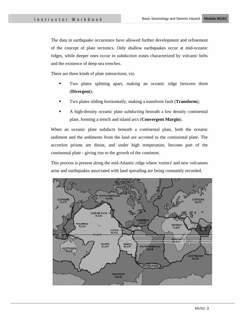
There are three kinds of plate interactions, viz.
Two plates splitting apart, making an oceanic ridge between them
(Divergent);
Two plates sliding horizontally, making a transform fault (Transform);
A high-density oceanic plate subducting beneath a low density continental
plate, forming a trench and island arcs (Convergent Margin).
When an oceanic plate subducts beneath a continental plate, both the oceanic
sediment and the sediments from the land are accreted to the continental plate. The
accretion prisms are thrust, and under high temperature, become part of the
continental plate - giving rise to the growth of the continent.
This process is present along the mid-Atlantic ridge where 'extinct' and new volcanoes
arise and earthquakes associated with land spreading are being constantly recorded.
M1/S1- 4
I n s t r u c t o r W o r k b o o k Basic Seismology and Seismic Hazard Module M1/S1
The whole world was one “supercontinent” called Pangaea 200 million years ago. The
current position of continents is the result of continuous movement in these 200
million years.
1.3 Seismogenic Fault Types
A fault or fault line is a planar fracture in rock in which the rock on one side of the
fracture has moved with respect to the rock on the other side. Large faults within the
Earth's crust are the result of differential or shear motion and active fault zones are the
causal locations of most earthquakes. Earthquakes are caused by energy release during
rapid slippage along a fault. A fault that runs along the boundary between two tectonic
plates is called a transform fault.
Since faults do not usually consist of a single, clean fracture, the term fault zone is
used when referring to the zone of complex deformation that is associated with the
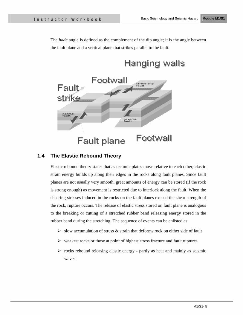
fault plane. The two sides of a non-vertical fault are called the hanging wall and
footwall. By definition, the hanging wall occurs above the fault and the footwall
occurs below the fault. This terminology comes from mining. When working in a
tabular ore body, the miner stood with the footwall under his feet and with the
hanging wall hanging above him.
Dip-slip faults are inclined fractures where the blocks have mostly shifted vertically.
If the rock mass above an inclined fault moves down, the fault is termed normal,
whereas if the rock above the fault moves up, the fault is termed reverse. A thrust
fault is a reverse fault with a dip of 45° or less. Oblique-slip faults have significant
components of different slip styles.
Strike-slip faults are vertical (or nearly vertical) fractures where the blocks have
mostly moved horizontally. If the block opposite an observer looking across the fault
moves to the right, the slip style is termed right lateral; if the block moves to the left,
the motion is termed left lateral.
Oblique-slip faulting suggests both dip-slip faulting and strike-slip faulting. It is
caused by a combination of shear and tension or compression forces. Nearly all faults
will have some component of both dip-slip (normal or reverse) and strike-slip, so
defining a fault as oblique requires both dip and strike components to be measurable
and significant.
M1/S1- 5
I n s t r u c t o r W o r k b o o k Basic Seismology and Seismic Hazard Module M1/S1
The hade angle is defined as the complement of the dip angle; it is the angle between
the fault plane and a vertical plane that strikes parallel to the fault.
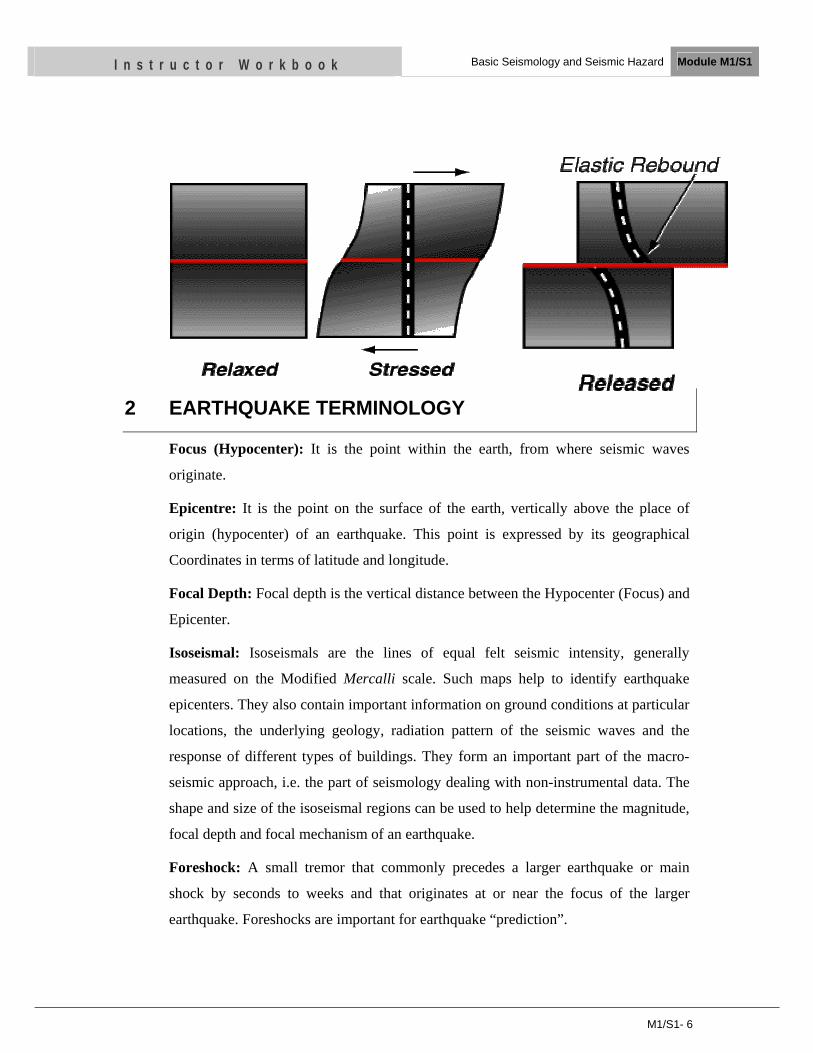
1.4 The Elastic Rebound Theory
Elastic rebound theory states that as tectonic plates move relative to each other, elastic
strain energy builds up along their edges in the rocks along fault planes. Since fault
planes are not usually very smooth, great amounts of energy can be stored (if the rock
is strong enough) as movement is restricted due to interlock along the fault. When the
shearing stresses induced in the rocks on the fault planes exceed the shear strength of
the rock, rupture occurs. The release of elastic stress stored on fault plane is analogous
to the breaking or cutting of a stretched rubber band releasing energy stored in the
rubber band during the stretching. The sequence of events can be enlisted as:
slow accumulation of stress & strain that deforms rock on either side of fault
weakest rocks or those at point of highest stress fracture and fault ruptures
rocks rebound releasing elastic energy - partly as heat and mainly as seismic
waves.
M1/S1- 6
I n s t r u c t o r W o r k b o o k Basic Seismology and Seismic Hazard Module M1/S1
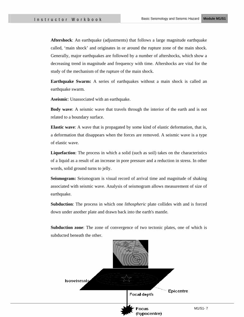
2 EARTHQUAKE TERMINOLOGY
Focus (Hypocenter): It is the point within the earth, from where seismic waves
originate.
Epicentre: It is the point on the surface of the earth, vertically above the place of
origin (hypocenter) of an earthquake. This point is expressed by its geographical
Coordinates in terms of latitude and longitude.
Focal Depth: Focal depth is the vertical distance between the Hypocenter (Focus) and
Epicenter.
Isoseismal: Isoseismals are the lines of equal felt seismic intensity, generally
measured on the Modified Mercalli scale. Such maps help to identify earthquake
epicenters. They also contain important information on ground conditions at particular
locations, the underlying geology, radiation pattern of the seismic waves and the
response of different types of buildings. They form an important part of the macro-
seismic approach, i.e. the part of seismology dealing with non-instrumental data. The
shape and size of the isoseismal regions can be used to help determine the magnitude,
focal depth and focal mechanism of an earthquake.
Foreshock: A small tremor that commonly precedes a larger earthquake or main
shock by seconds to weeks and that originates at or near the focus of the larger
earthquake. Foreshocks are important for earthquake “prediction”.
M1/S1- 7
I n s t r u c t o r W o r k b o o k Basic Seismology and Seismic Hazard Module M1/S1
Aftershock: An earthquake (adjustments) that follows a large magnitude earthquake
called, ‘main shock’ and originates in or around the rupture zone of the main shock.
Generally, major earthquakes are followed by a number of aftershocks, which show a
decreasing trend in magnitude and frequency with time. Aftershocks are vital for the
study of the mechanism of the rupture of the main shock.
Earthquake Swarm: A series of earthquakes without a main shock is called an
earthquake swarm.
Aseismic: Unassociated with an earthquake.
Body wave: A seismic wave that travels through the interior of the earth and is not
related to a boundary surface.
Elastic wave: A wave that is propagated by some kind of elastic deformation, that is,
a deformation that disappears when the forces are removed. A seismic wave is a type
of elastic wave.
Liquefaction: The process in which a solid (such as soil) takes on the characteristics
of a liquid as a result of an increase in pore pressure and a reduction in stress. In other
words, solid ground turns to jelly.
Seismogram: Seismogram is visual record of arrival time and magnitude of shaking
associated with seismic wave. Analysis of seismogram allows measurement of size of
earthquake.
Subduction: The process in which one lithospheric plate collides with and is forced
down under another plate and drawn back into the earth's mantle.
Subduction zone: The zone of convergence of two tectonic plates, one of which is
subducted beneath the other.
M1/S1- 8
I n s t r u c t o r W o r k b o o k Basic Seismology and Seismic Hazard Module M1/S1
3 SEISMIC WAVE GENERATION
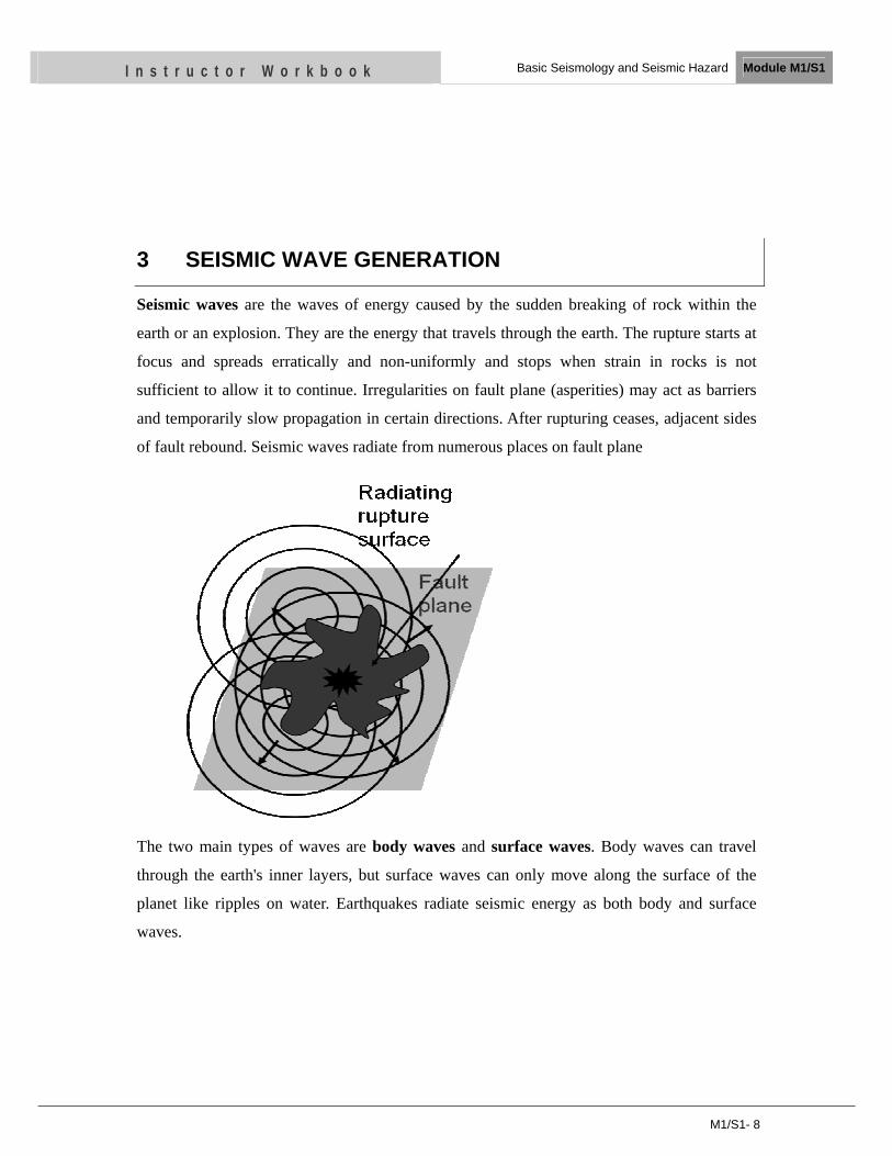
Seismic waves are the waves of energy caused by the sudden breaking of rock within the
earth or an explosion. They are the energy that travels through the earth. The rupture starts at
focus and spreads erratically and non-uniformly and stops when strain in rocks is not
sufficient to allow it to continue. Irregularities on fault plane (asperities) may act as barriers
and temporarily slow propagation in certain directions. After rupturing ceases, adjacent sides
of fault rebound. Seismic waves radiate from numerous places on fault plane
The two main types of waves are body waves and surface waves. Body waves can travel
through the earth's inner layers, but surface waves can only move along the surface of the
planet like ripples on water. Earthquakes radiate seismic energy as both body and surface
waves.
M1/S1- 9
I n s t r u c t o r W o r k b o o k Basic Seismology and Seismic Hazard Module M1/S1
3.1 Body Waves
Traveling through the interior of the earth, body waves arrive before the surface waves
emitted by an earthquake. These waves are of a higher frequency than surface waves. There
are two types of body waves as primary (push) and secondary waves.
3.1.1 P (Primary or Push) Waves
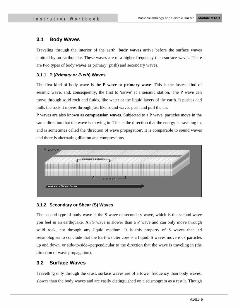
The first kind of body wave is the P wave or primary wave. This is the fastest kind of
seismic wave, and, consequently, the first to 'arrive' at a seismic station. The P wave can
move through solid rock and fluids, like water or the liquid layers of the earth. It pushes and
pulls the rock it moves through just like sound waves push and pull the air.
P waves are also known as compression waves. Subjected to a P wave, particles move in the
same direction that the wave is moving in. This is the direction that the energy is traveling in,
and is sometimes called the 'direction of wave propagation'. It is comparable to sound waves
and there is alternating dilation and compressions.
3.1.2 Secondary or Shear (S) Waves
The second type of body wave is the S wave or secondary wave, which is the second wave
you feel in an earthquake. An S wave is slower than a P wave and can only move through
solid rock, not through any liquid medium. It is this property of S waves that led
seismologists to conclude that the Earth's outer core is a liquid. S waves move rock particles
up and down, or side-to-side--perpendicular to the direction that the wave is traveling in (the
direction of wave propagation).
3.2 Surface Waves
Travelling only through the crust, surface waves are of a lower frequency than body waves;
slower than the body waves and are easily distinguished on a seismogram as a result. Though
M1/S1- 10
I n s t r u c t o r W o r k b o o k Basic Seismology and Seismic Hazard Module M1/S1
they arrive after body waves, it is surface waves that are almost entirely responsible for the
damage and destruction associated with earthquakes. The damage and the strength of the
surface waves are reduced in deeper earthquakes.
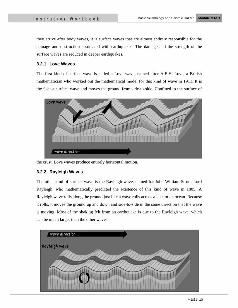
3.2.1 Love Waves
The first kind of surface wave is called a Love wave, named after A.E.H. Love, a British
mathematician who worked out the mathematical model for this kind of wave in 1911. It is
the fastest surface wave and moves the ground from side-to-side. Confined to the surface of
the crust, Love waves produce entirely horizontal motion.
3.2.2 Rayleigh Waves
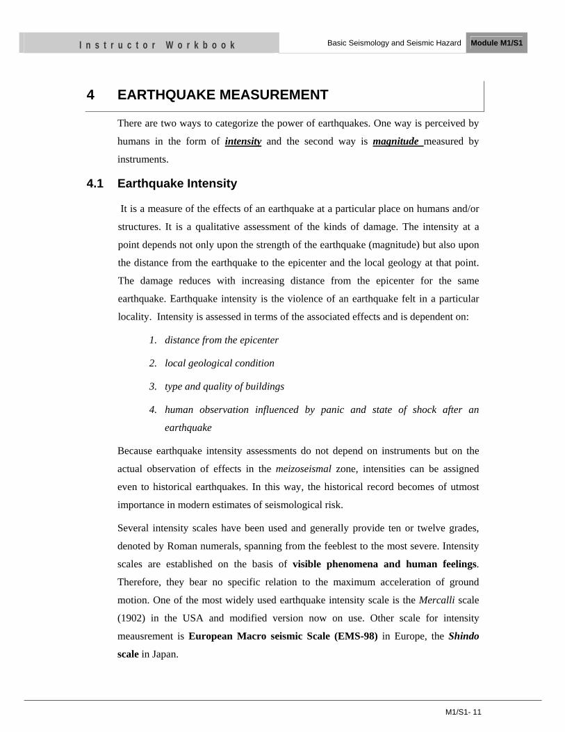
The other kind of surface wave is the Rayleigh wave, named for John William Strutt, Lord
Rayleigh, who mathematically predicted the existence of this kind of wave in 1885. A
Rayleigh wave rolls along the ground just like a wave rolls across a lake or an ocean. Because
it rolls, it moves the ground up and down and side-to-side in the same direction that the wave
is moving. Most of the shaking felt from an earthquake is due to the Rayleigh wave, which
can be much larger than the other waves.
M1/S1- 11
I n s t r u c t o r W o r k b o o k Basic Seismology and Seismic Hazard Module M1/S1
4 EARTHQUAKE MEASUREMENT
There are two ways to categorize the power of earthquakes. One way is perceived by
humans in the form of intensity and the second way is magnitude measured by
instruments.
4.1 Earthquake Intensity
It is a measure of the effects of an earthquake at a particular place on humans and/or
structures. It is a qualitative assessment of the kinds of damage. The intensity at a
point depends not only upon the strength of the earthquake (magnitude) but also upon
the distance from the earthquake to the epicenter and the local geology at that point.
The damage reduces with increasing distance from the epicenter for the same
earthquake. Earthquake intensity is the violence of an earthquake felt in a particular
locality. Intensity is assessed in terms of the associated effects and is dependent on:
1. distance from the epicenter
2. local geological condition
3. type and quality of buildings
4. human observation influenced by panic and state of shock after an
earthquake
Because earthquake intensity assessments do not depend on instruments but on the
actual observation of effects in the meizoseismal zone, intensities can be assigned
even to historical earthquakes. In this way, the historical record becomes of utmost
importance in modern estimates of seismological risk.
Several intensity scales have been used and generally provide ten or twelve grades,
denoted by Roman numerals, spanning from the feeblest to the most severe. Intensity
scales are established on the basis of visible phenomena and human feelings.
Therefore, they bear no specific relation to the maximum acceleration of ground
motion. One of the most widely used earthquake intensity scale is the Mercalli scale
(1902) in the USA and modified version now on use. Other scale for intensity
meausrement is European Macro seismic Scale (EMS-98) in Europe, the Shindo
scale in Japan.
M1/S1- 12
I n s t r u c t o r W o r k b o o k Basic Seismology and Seismic Hazard Module M1/S1
4.1.1 Modified Mercalli Intensity Scale
(from FEMA)
I. People do not feel any Earth movement.
II. A few people might notice movement if they are at rest and/or on the upper
floors of tall buildings.
III. Many people indoors feel movement. Hanging objects swing back and forth.
People outdoors might not realize that an earthquake is occurring.
IV. Most people indoors feel movement. Hanging objects swing. Dishes,
windows, and doors rattle. The earthquake feels like a heavy truck hitting the
walls. A few people outdoors may feel movement. Parked cars rock.
V. Almost everyone feels movement. Sleeping people are awakened. Doors
swing open or close. Dishes are broken. Pictures on the wall move. Small
objects move or are turned over. Trees might shake. Liquids might spill out of
open containers.
VI. Everyone feels movement. People have trouble walking. Objects fall from
shelves. Pictures fall off walls. Furniture moves. Plaster in walls might crack.
Trees and bushes shake. Damage is slight in poorly built buildings. No
structural damage.
VII. People have difficulty standing. Drivers feel their cars shaking. Some furniture
breaks. Loose bricks fall from buildings. Damage is slight to moderate in well-
built buildings; considerable in poorly built buildings.
VIII. Drivers have trouble steering. Houses that are not bolted down might shift on
their foundations. Tall structures such as towers and chimneys might twist and
fall. Well-built buildings suffer slight damage. Poorly built structures suffer
severe damage. Tree branches break. Hillsides might crack if the ground is
wet. Water levels in wells might change.
IX. Well-built buildings suffer considerable damage. Houses that are not bolted
down move off their foundations. Some underground pipes are broken. The
ground cracks. Reservoirs suffer serious damage.
X. Most buildings and their foundations are destroyed. Some bridges are
destroyed. Dams are seriously damaged. Large landslides occur. Water is
M1/S1- 13
I n s t r u c t o r W o r k b o o k Basic Seismology and Seismic Hazard Module M1/S1
thrown on the banks of canals, rivers, lakes. The ground cracks in large areas.
Railroad tracks are bent slightly.
XI. Most buildings collapse. Some bridges are destroyed. Large cracks appear in
the ground. Underground pipelines are destroyed. Railroad tracks are badly
bent.
XII. Almost everything is destroyed. Objects are thrown into the air. The ground
moves in waves or ripples. Large amounts of rock may move.
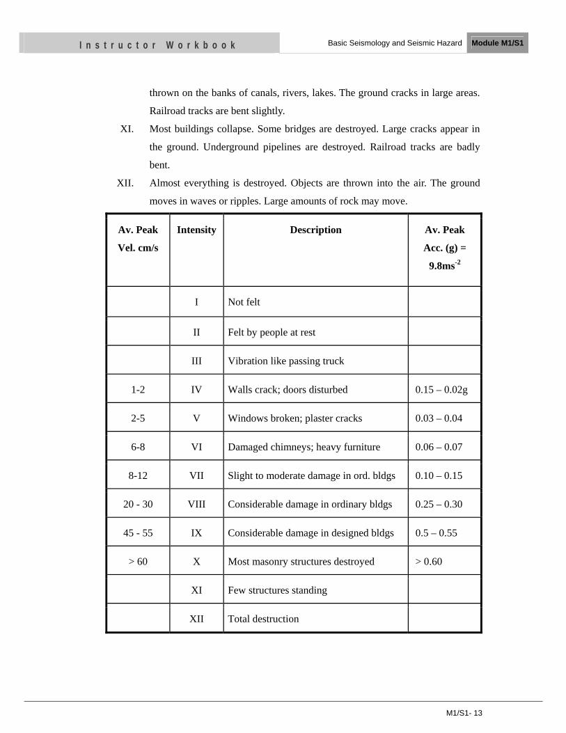
Av. Peak
Vel. cm/s
Intensity Description Av. Peak
Acc. (g) =
9.8ms-2
I Not felt
II Felt by people at rest
III Vibration like passing truck
1-2 IV Walls crack; doors disturbed 0.15 – 0.02g
2-5 V Windows broken; plaster cracks 0.03 – 0.04
6-8 VI Damaged chimneys; heavy furniture 0.06 – 0.07
8-12 VII Slight to moderate damage in ord. bldgs 0.10 – 0.15
20 - 30 VIII Considerable damage in ordinary bldgs 0.25 – 0.30
45 - 55 IX Considerable damage in designed bldgs 0.5 – 0.55
> 60 X Most masonry structures destroyed > 0.60
XI Few structures standing
XII Total destruction
M1/S1- 14
I n s t r u c t o r W o r k b o o k Basic Seismology and Seismic Hazard Module M1/S1
4.2 Earthquake Magnitude
It is a quantity to measure the size of an earthquake and is independent of the place of
the observation. It is a quantitative measure of the strength of an earthquake.
Magnitude is calculated from ground motion as measured by seismograph and
incorporates the distance of the seismograph from the earthquake epicenter so that,
theoretically, the magnitude calculated for an earthquake would be the same from any
seismograph station recording that earthquake. The magnitude of most earthquakes is
measured on the Richter scale, invented by Charles F. Richter in 1934. The Richter
magnitude is calculated from the amplitude of the largest seismic wave recorded for
the earthquake, no matter what type of wave was the strongest.
The Richter magnitudes are based on a logarithmic scale (base 10). What this means
is that for each whole number we go up on the Richter scale, the amplitude of the
ground motion recorded by a seismograph goes up ten times. The record of actual
ground motion amplitude provides a relatively precise method for representing the
size of an earthquake. It is closely related to the energy released in an earthquake.
Only a few percent of the released energy is radiated in the form of seismic waves.
But since these waves are responsible for the ground motion and for the resulting
damage to buildings and structures, this radiated energy is referred as the seismic
energy of the earthquake. Using this scale, an earthquake of magnitude 5 would result
in ten times the level of ground shaking as an earthquake of magnitude 4 (and 32
times much energy would be released).
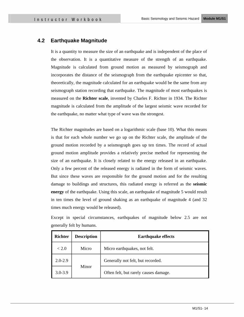
Except in special circumstances, earthquakes of magnitude below 2.5 are not
generally felt by humans.
Richter Description Earthquake effects
< 2.0 Micro Micro earthquakes, not felt.
2.0-2.9 Minor
Generally not felt, but recorded.
3.0-3.9 Often felt, but rarely causes damage.
M1/S1- 15
I n s t r u c t o r W o r k b o o k Basic Seismology and Seismic Hazard Module M1/S1
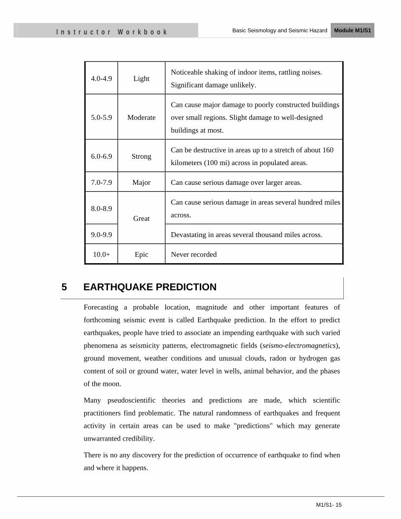
4.0-4.9 Light Noticeable shaking of indoor items, rattling noises.
Significant damage unlikely.
5.0-5.9 Moderate
Can cause major damage to poorly constructed buildings
over small regions. Slight damage to well-designed
buildings at most.
6.0-6.9 Strong Can be destructive in areas up to a stretch of about 160
kilometers (100 mi) across in populated areas.
7.0-7.9 Major Can cause serious damage over larger areas.
8.0-8.9 Great
Can cause serious damage in areas several hundred miles
across.
9.0-9.9 Devastating in areas several thousand miles across.
10.0+ Epic Never recorded
5 EARTHQUAKE PREDICTION
Forecasting a probable location, magnitude and other important features of
forthcoming seismic event is called Earthquake prediction. In the effort to predict
earthquakes, people have tried to associate an impending earthquake with such varied
phenomena as seismicity patterns, electromagnetic fields (seismo-electromagnetics),
ground movement, weather conditions and unusual clouds, radon or hydrogen gas
content of soil or ground water, water level in wells, animal behavior, and the phases
of the moon.
Many pseudoscientific theories and predictions are made, which scientific
practitioners find problematic. The natural randomness of earthquakes and frequent
activity in certain areas can be used to make "predictions" which may generate
unwarranted credibility.
There is no any discovery for the prediction of occurrence of earthquake to find when
and where it happens.
M1/S1- 16
I n s t r u c t o r W o r k b o o k Basic Seismology and Seismic Hazard Module M1/S1
5.1 Long Term Forecast
The study of regional seismicity and the outline of seismic zones make it possible,
within the framework of Plate Tectonics, to forecast the regions in which earthquakes
will occur. Earthquake catalogs of a region, or the magnitude-frequency plot for the
region, help on statistical basis, to anticipate (make a long-term forecast of)
earthquakes. This is useful to develop strategy, which reduce human and material
losses.
5.2 Short-term Prediction
Short-term prediction implies the ability to specify in advance the exact place, date (as
precisely as possible) and magnitude of a future earthquake.
Despite extensive research in advanced countries, the system of earthquake prediction
has not attained the level to use confidently outside experimental environments. Many
questions on the cost-effectiveness of prediction, especially in developing countries,
have been raised. The money could be better spent on reducing vulnerability of
existing structures.
6 SEISMIC HAZARDS
Earthquake has two types of hazards: primary and secondary hazards.
The primary hazard resulting from an earthquake is the ground movement and
shaking. Surface seismic waves cause most severe hazards to human viz.:
• Building collapse - Damage to buildings and other structures will differ according
to the surface materials they are built on. Solid bed rock is more stable than
unconsolidated sediments which can amplify the shaking.
• Underground pipes and power lines may be severed by ground motion resulting in
fires and explosions
• Ruptured water pipes mean no water to extinguish fires.
Secondary hazards are soil liquefaction, landslides, avalanches and tsunamis.
Soil Liquefaction: Liquefaction is a condition when a solid material turns into a
liquefied state due to an increase in water pressures of the pore as a result of ground
M1/S1- 17
I n s t r u c t o r W o r k b o o k Basic Seismology and Seismic Hazard Module M1/S1
shaking during an earthquake and the strength and stiffness of a soil is reduced. It
occurs in saturated soils, that is, soils in which the space between individual particles
is completely filled with water. This water exerts a pressure on the soil particles that
influences how tightly the particles themselves are pressed together. Prior to an
earthquake, the water pressure is relatively low. However, earthquake shaking can
cause the water pressure to increase to the point where the soil particles can readily
move with respect to each other. Structures such as bridges, dams and subsurface
pipes will be damaged apart from structures standing on such soil base. Liquefaction
and related phenomena have been responsible for tremendous amounts of damage in
historical earthquakes around the world.
Landslides: Sudden mass movement of soil can result from the earthquakes. The
stress resulting from the ground shaking of an earthquake can result in slope failure on
even gentle slopes. Landslides, rock and snow avalanches can overrun people and
structures, cause building collapse, break underground pipes and disrupt rescue efforts
by blocking roads. In many earthquakes the land sliding has caused as much more
damage than the ground shaking.
Tsunami: A Tsunami, Japanese word for harbor wave, is a series of huge waves that
occur after an undersea disturbance, such as an earthquake or volcano eruption. The
waves travel in all directions from the area of disturbance, much like the ripples that
take place after throwing a rock. The waves may travel in the open sea as fast as 450
miles per hour. As the big waves approach shallow waters along the coast they grow
to a great height and smash into the shore. They can be as high as 100 feet. They can
cause a lot of destruction on the shore.
Fire: Fire is one of the most devastation events after the earthquake and it may be
resulted from the principal ignition sources as overturning of electrical appliances,
short-circuiting of electrical equipment, gas leakage from damaged equipment and
pipe work and leakage of flammable fluids (including fuels for emergency generators
etc.). Spillage of chemicals may also be a potential ignition source in buildings where
they are utilized or stored.
M1/S1- 18
I n s t r u c t o r W o r k b o o k Basic Seismology and Seismic Hazard Module M1/S1
UNIT TEST
1. Name three layers of the earth
2. Write three kinds of plate interactions.
3. Write the kinds of seismic body waves.
4. Write the kinds of seismic surface waves.
5. Write two ways of earthquakes measurement?
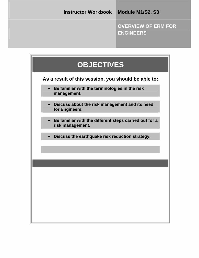
OBJECTIVES
As a result of this session, you should be able to:
• Be familiar with the terminologies in the risk management.
• Discuss about the risk management and its need for Engineers.
• Be familiar with the different steps carried out for a risk management.
• Discuss the earthquake risk reduction strategy.
Instructor Workbook Module M1/S2, S3
OVERVIEW OF ERM FOR ENGINEERS
CONTENTS
1 Terminologies in ERM ..................................................................................... 2 2 Risk Management ............................................................................................. 3
2.1 Primary and Secondary Hazard of Earthquake ......................................... 4
2.2 Relative Vulnerability indicators for earthquake ...................................... 4
2.3 Earthquake Lethality Potential .................................................................. 5
3 Earthquake Risk Reduction Strategy ........................................................... 11 4 Challenges for Earthquake Risk Mitigation ................................................ 13
M1/S2, S3-2
I n s t r u c t o r W o r k b o o k Overview of ERM for Engineers Module M1/S2, S3
1 TERMINOLOGIES IN ERM
Risk - Risk is the chance of something happening that will impact positively or negatively on
outcomes. A risk may be specified in terms of an event or circumstances or the consequence
that flow from the event or circumstances. It is measured in terms of the consequences of the
event and the likelihood of its occurring.
Hazard - A natural event that has potential to cause harm or loss. A Hazard is a threat, a
future source of danger. Occurrence of an earthquake of sufficient Magnitude is capable of
causing damage to the man-made structures.
Vulnerability - Vulnerability is a condition to cause damage and loss - damageability of the
`exposure' under the action of the hazard; weaker ones being more vulnerable and `risky'
than the stronger ones. It depends on condition of structures, location and exposure to
environment.
Risk = hazard x vulnerability
Vulnerability is a combination of two things: susceptibility and resilience. Resilience is how
well a community is able to sustain loss, and susceptibility is the degree of exposure to risk.
In other words, when determining the vulnerability of a community to a hazard impact, it is
necessary to establish the capabilities of the community and environment to anticipate, cope
with and recover from disasters.
For instance, if a community is likely to experience a disaster but has a limited ability to
sustain loss and damage, the community is very vulnerable. On the other hand, if a
community is not likely to experience a hazard impact but has the ability to withstand loss
and damage, the community is not so vulnerable to disasters.
high susceptibility x low resilience = high level of vulnerability
(high exposure to risk x limited ability to sustain loss = high vulnerability)
low susceptibility x high resilience = low degree of vulnerability
(ability to sustain loss x low degree of exposure = low vulnerability)
Preparedness – Plans and programs, systems and procedures, training and education to
ensure that if disasters do occur, resources (personnel and equipment) can be mobilized and
deployed to best effect.

M1/S2, S3-3
I n s t r u c t o r W o r k b o o k Overview of ERM for Engineers Module M1/S2, S3
Damage - The physical disruption due to an earthquake such as collapsed buildings, walls,
fixtures, damaged highways etc.
Loss - The human and financial consequences of damage, including injuries or deaths, the
costs of repair, of loss of revenue.
Mitigation - Any measure taken to reduce the earthquake risk. Mitigation can take many
forms, including building strengthening, occupancy reduction, change of function, equipment
anchoring or bracing, effective emergency and contingency planning.
Decision making – The process of analyzing data on the above issues and putting them into a
rational framework whereby certain mitigation alternatives emerge as the most appropriate
solution for the specific situation.
Implementation - Putting the mitigation program into action.
2 RISK MANAGEMENT
It will rarely be possible to eliminate risks entirely. All life involves some risk, and any
innovation brings risk as well as reward. So the priority must be to manage risks better. We
need to do more to anticipate risks, so that there are fewer unnecessary and costly crises, and
to ensure that risk management is an integral part of all delivery plans. Risk managers will
always have to make decisions under uncertainty with limited resources at hand. Risk
Management is the culture, processes and structures that are directed towards risk
identification, risk assessment as well as decision making to ensure effective risk control and
its implementation. Thus it is the process of analyzing exposure to risk and determining how
to best handle such exposure, or the optimal allocation of resources to arrive at an efficient
and cost effective investment in defensive measures to cope with the impact of disasters
through strengthening policy response to hazard and alerting the public to their role in
reducing vulnerability. Reducing vulnerability to natural disasters is a key factor to enhance
sustainable development. There is a specific need to strengthen the integral risk management
as well as the need to further develop the technological, institutional and human capacities of
all relevant key actors. Proper disaster risk management, however, can help to minimize the
consequences of this natural threat. Risk management is an important element in the work or
practice of a professional engineer, a good manager. For this, awareness of, and competence
in, risk management are necessary for all Engineers. The following steps shall be carried out
for a risk management plan:
M1/S2, S3-4
I n s t r u c t o r W o r k b o o k Overview of ERM for Engineers Module M1/S2, S3
1. Identify Hazards
2. Profile Hazards
3. Assess Vulnerability
• Identify Structures
• Estimate Potential Losses
• Analyze Development Trends
4. Develop Local Hazard Mitigation Goals
5. Identify and Analyze Mitigation Actions
6. Implement Mitigation Actions
7. Monitor, Evaluate, and Update the Plan
2.1 Primary and Secondary Hazard of Earthquake
The earthquake causes a variety of earthquake hazards. Building and other structures may not
resist fully these hazards and sustain some degree of primary damage. Depending on the
severity of the hazards and the vulnerability of the construction, primary damage can range
from minor cracking to total collapse. Even when a building sustains no structural damage, its
contents may be severely damaged. For certain occupancies, such as hospitals or emergency
communication centers, damage to contents can be catastrophic. For any building, it is
expensive and time consuming to repair. Primary damage can lead to secondary forms of
hazards and damage such as releases of hazardous materials, major fires or flooding. Damage
results in loss. Primary loss can take many forms, but loss of life or injury is the major
concern. Financial as well as functional losses are also serious issues. The likelihood to
sustain a loss is termed as a risk. Primary losses lead to secondary loss of revenues.
2.2 Relative Vulnerability indicators for earthquake
Disasters are more deadly in poor countries. Disaster risk index enables experts to measure
and compare physical exposure to hazard, vulnerability and risk between countries and
demonstrates a clear link between human development and death rates following the
disasters. Approximately 130 million are exposed to earthquake per year. High vulnerability
M1/S2, S3-5
I n s t r u c t o r W o r k b o o k Overview of ERM for Engineers Module M1/S2, S3
to earthquakes was found in countries such as Iran, Afghanistan and India. Other medium
developed countries with sizeable urban populations such as Turkey and the Russian
Federation were also found to have high levels of vulnerability. The Islamic Republic of Iran
is approximately 1000 times more vulnerable than the United States of America and 100
times more vulnerable that Japan. Italy has a higher relative vulnerability than Mexico or
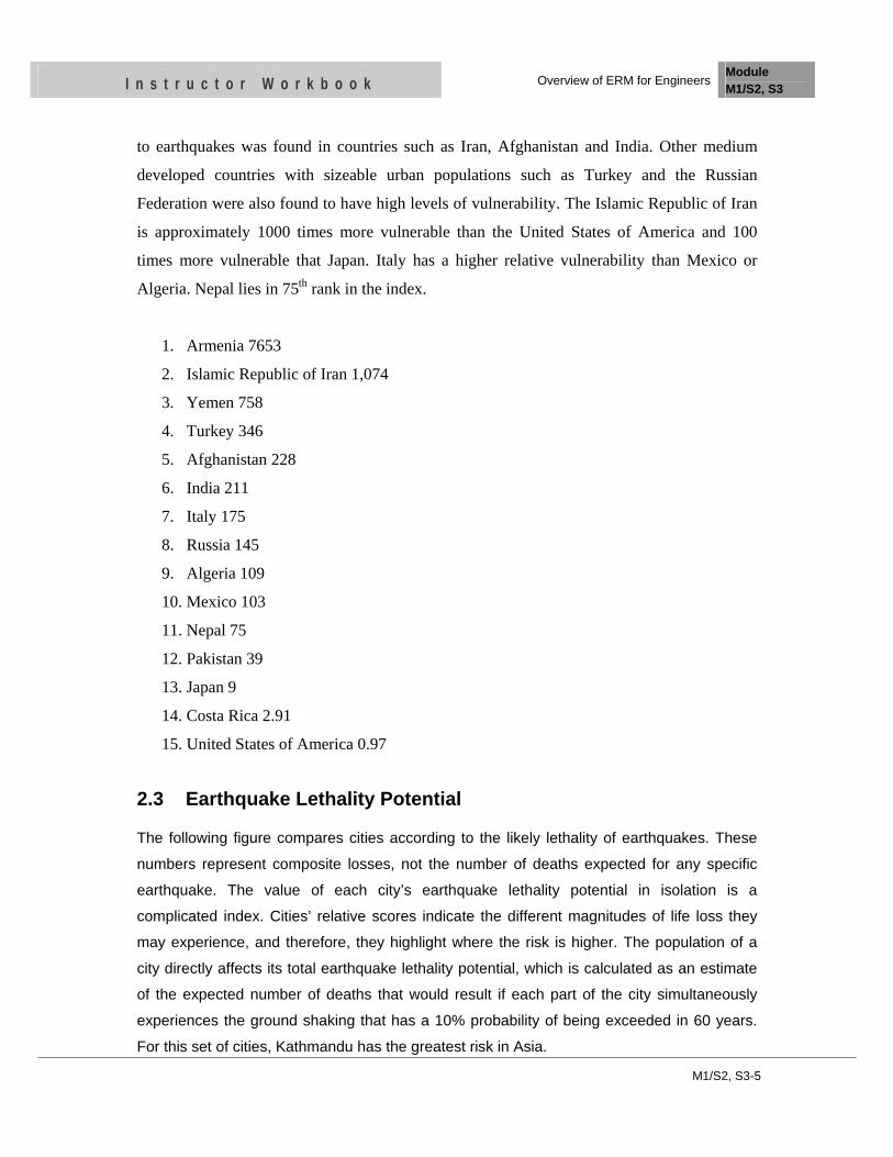
Algeria. Nepal lies in 75th rank in the index.
1. Armenia 7653
2. Islamic Republic of Iran 1,074
3. Yemen 758
4. Turkey 346
5. Afghanistan 228
6. India 211
7. Italy 175
8. Russia 145
9. Algeria 109
10. Mexico 103
11. Nepal 75
12. Pakistan 39
13. Japan 9
14. Costa Rica 2.91
15. United States of America 0.97
2.3 Earthquake Lethality Potential
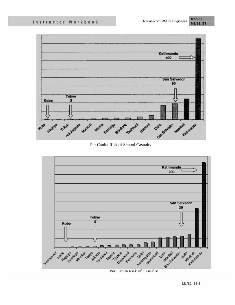
The following figure compares cities according to the likely lethality of earthquakes. These
numbers represent composite losses, not the number of deaths expected for any specific
earthquake. The value of each city’s earthquake lethality potential in isolation is a
complicated index. Cities’ relative scores indicate the different magnitudes of life loss they
may experience, and therefore, they highlight where the risk is higher. The population of a
city directly affects its total earthquake lethality potential, which is calculated as an estimate
of the expected number of deaths that would result if each part of the city simultaneously
experiences the ground shaking that has a 10% probability of being exceeded in 60 years.
For this set of cities, Kathmandu has the greatest risk in Asia.
M1/S2, S3-6
I n s t r u c t o r W o r k b o o k Overview of ERM for Engineers Module M1/S2, S3
Per Capita Risk of Casualty
Per Capita Risk of School Casualty
M1/S2, S3-7
I n s t r u c t o r W o r k b o o k Overview of ERM for Engineers Module M1/S2, S3
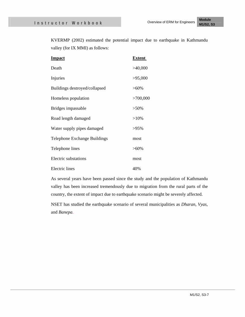
KVERMP (2002) estimated the potential impact due to earthquake in Kathmandu
valley (for IX MMI) as follows:
Impact Extent
Death >40,000
Injuries >95,000
Buildings destroyed/collapsed >60%
Homeless population >700,000
Bridges impassable >50%
Road length damaged >10%
Water supply pipes damaged >95%
Telephone Exchange Buildings most
Telephone lines >60%
Electric substations most
Electric lines 40%
As several years have been passed since the study and the population of Kathmandu
valley has been increased tremendously due to migration from the rural parts of the
country, the extent of impact due to earthquake scenario might be severely affected.
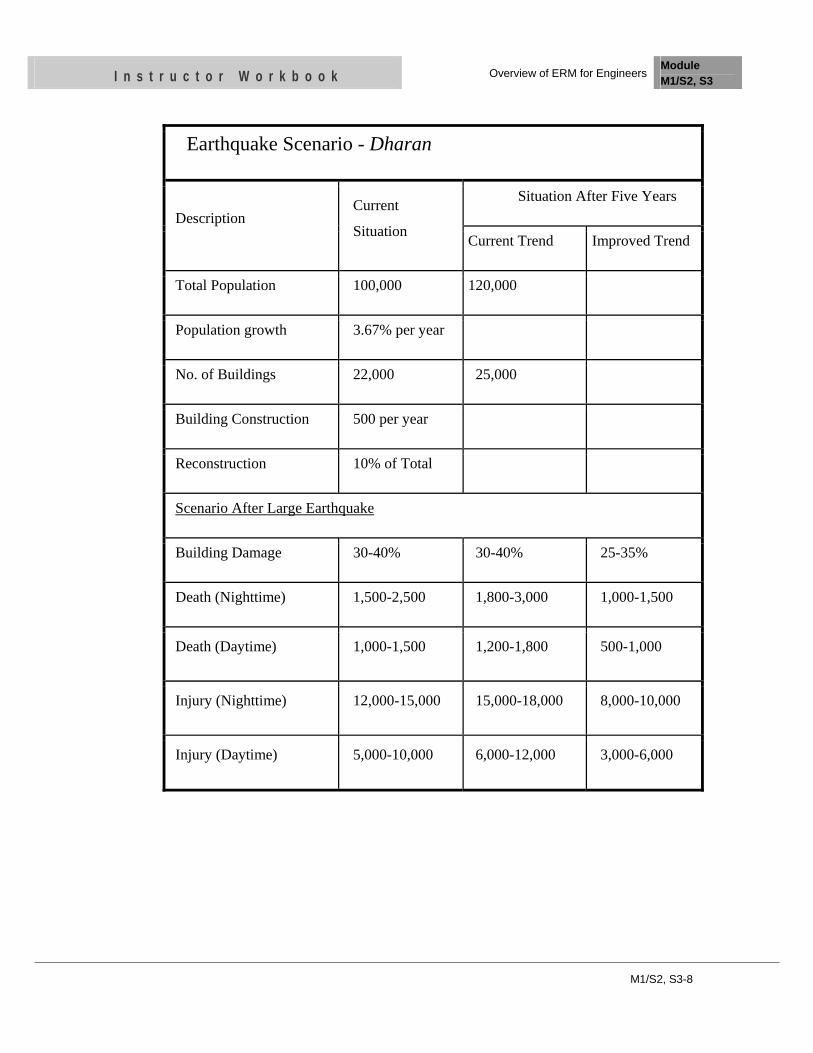
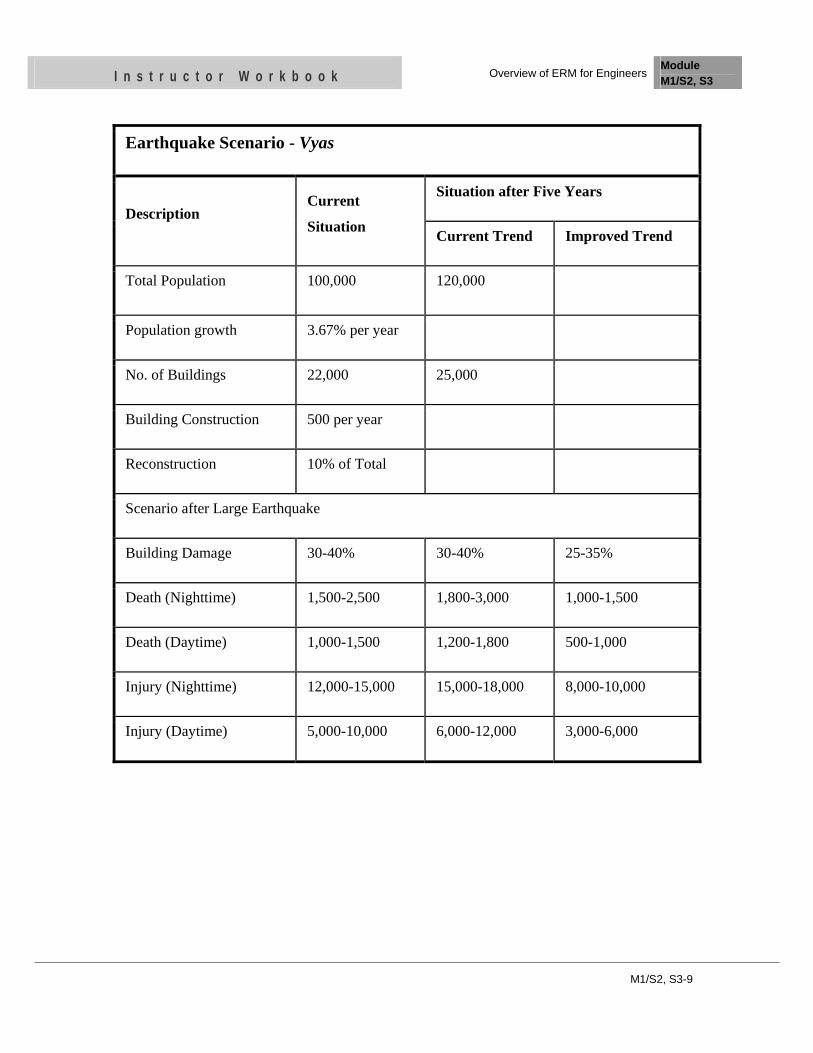
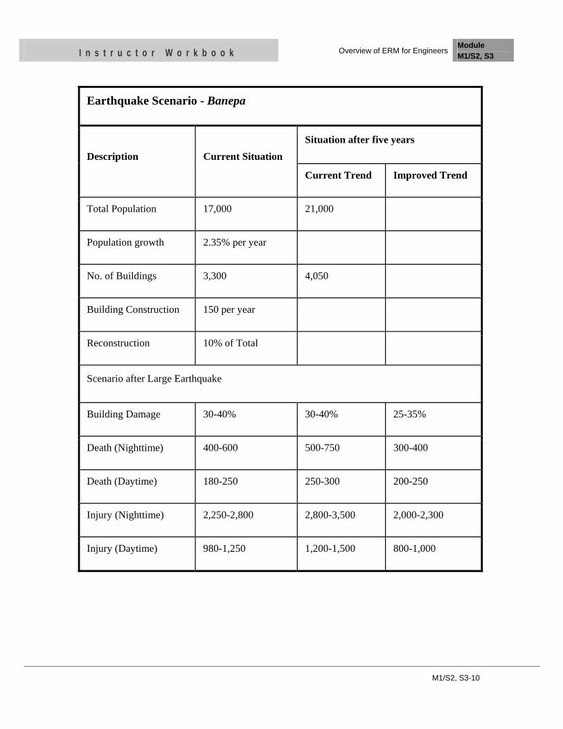
NSET has studied the earthquake scenario of several municipalities as Dharan, Vyas,
and Banepa.
M1/S2, S3-8
I n s t r u c t o r W o r k b o o k Overview of ERM for Engineers Module M1/S2, S3
Earthquake Scenario - Dharan
Description Current
Situation
Situation After Five Years
Current Trend Improved Trend
Total Population 100,000 120,000
Population growth 3.67% per year
No. of Buildings 22,000 25,000
Building Construction 500 per year
Reconstruction 10% of Total
Scenario After Large Earthquake
Building Damage 30-40% 30-40% 25-35%
Death (Nighttime) 1,500-2,500 1,800-3,000 1,000-1,500
Death (Daytime) 1,000-1,500 1,200-1,800 500-1,000
Injury (Nighttime) 12,000-15,000 15,000-18,000 8,000-10,000
Injury (Daytime) 5,000-10,000 6,000-12,000 3,000-6,000
M1/S2, S3-9
I n s t r u c t o r W o r k b o o k Overview of ERM for Engineers Module M1/S2, S3
Earthquake Scenario - Vyas
Description Current
Situation
Situation after Five Years
Current Trend Improved Trend
Total Population 100,000 120,000
Population growth 3.67% per year
No. of Buildings 22,000 25,000
Building Construction 500 per year
Reconstruction 10% of Total
Scenario after Large Earthquake
Building Damage 30-40% 30-40% 25-35%
Death (Nighttime) 1,500-2,500 1,800-3,000 1,000-1,500
Death (Daytime) 1,000-1,500 1,200-1,800 500-1,000
Injury (Nighttime) 12,000-15,000 15,000-18,000 8,000-10,000
Injury (Daytime) 5,000-10,000 6,000-12,000 3,000-6,000
M1/S2, S3-10
I n s t r u c t o r W o r k b o o k Overview of ERM for Engineers Module M1/S2, S3
Earthquake Scenario - Banepa
Description Current Situation Situation after five years
Current Trend Improved Trend
Total Population 17,000 21,000
Population growth 2.35% per year
No. of Buildings 3,300 4,050
Building Construction 150 per year
Reconstruction 10% of Total
Scenario after Large Earthquake
Building Damage 30-40% 30-40% 25-35%
Death (Nighttime) 400-600 500-750 300-400
Death (Daytime) 180-250 250-300 200-250
Injury (Nighttime) 2,250-2,800 2,800-3,500 2,000-2,300
Injury (Daytime) 980-1,250 1,200-1,500 800-1,000
M1/S2, S3-11
I n s t r u c t o r W o r k b o o k Overview of ERM for Engineers Module M1/S2, S3
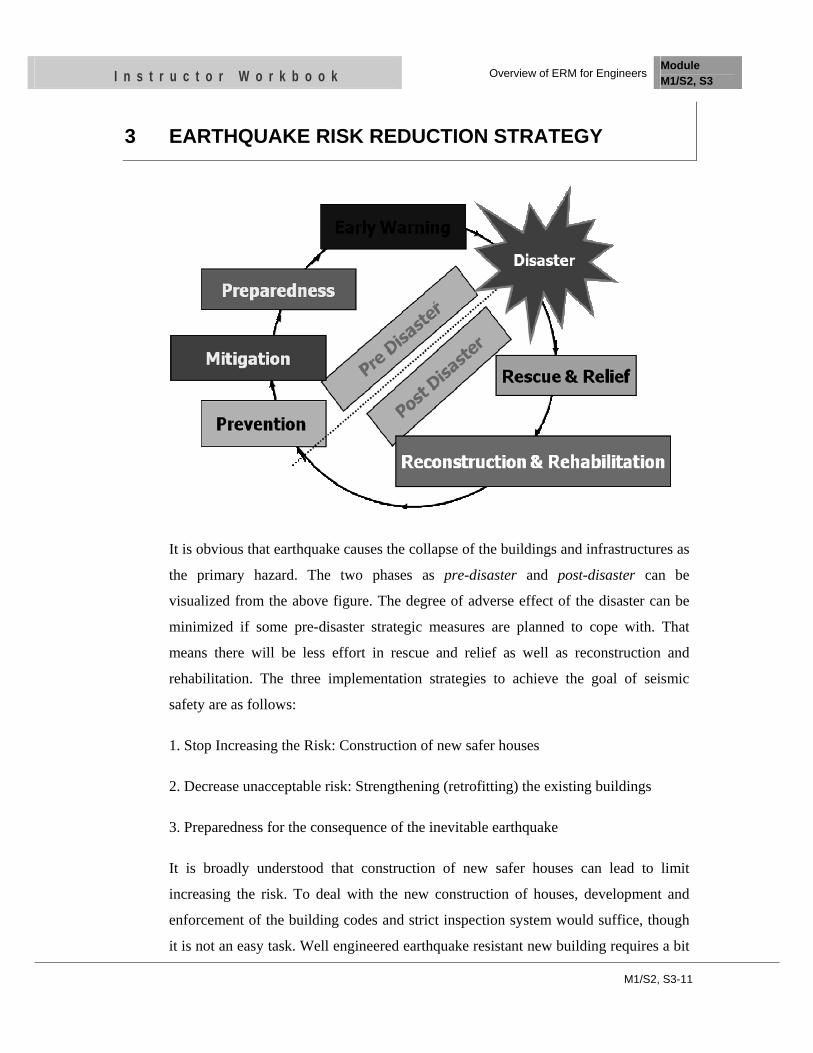
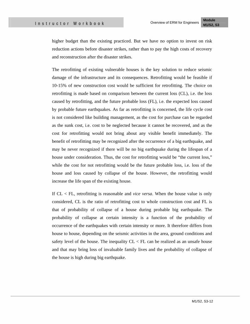
3 EARTHQUAKE RISK REDUCTION STRATEGY
It is obvious that earthquake causes the collapse of the buildings and infrastructures as
the primary hazard. The two phases as pre-disaster and post-disaster can be
visualized from the above figure. The degree of adverse effect of the disaster can be
minimized if some pre-disaster strategic measures are planned to cope with. That
means there will be less effort in rescue and relief as well as reconstruction and
rehabilitation. The three implementation strategies to achieve the goal of seismic
safety are as follows:
1. Stop Increasing the Risk: Construction of new safer houses
2. Decrease unacceptable risk: Strengthening (retrofitting) the existing buildings
3. Preparedness for the consequence of the inevitable earthquake
It is broadly understood that construction of new safer houses can lead to limit
increasing the risk. To deal with the new construction of houses, development and
enforcement of the building codes and strict inspection system would suffice, though
it is not an easy task. Well engineered earthquake resistant new building requires a bit
M1/S2, S3-12
I n s t r u c t o r W o r k b o o k Overview of ERM for Engineers Module M1/S2, S3
higher budget than the existing practiced. But we have no option to invest on risk
reduction actions before disaster strikes, rather than to pay the high costs of recovery
and reconstruction after the disaster strikes.
The retrofitting of existing vulnerable houses is the key solution to reduce seismic
damage of the infrastructure and its consequences. Retrofitting would be feasible if
10-15% of new construction cost would be sufficient for retrofitting. The choice on
retrofitting is made based on comparison between the current loss (CL), i.e. the loss
caused by retrofitting, and the future probable loss (FL), i.e. the expected loss caused
by probable future earthquakes. As far as retrofitting is concerned, the life cycle cost
is not considered like building management, as the cost for purchase can be regarded
as the sunk cost, i.e. cost to be neglected because it cannot be recovered, and as the
cost for retrofitting would not bring about any visible benefit immediately. The
benefit of retrofitting may be recognized after the occurrence of a big earthquake, and
may be never recognized if there will be no big earthquake during the lifespan of a
house under consideration. Thus, the cost for retrofitting would be “the current loss,”
while the cost for not retrofitting would be the future probable loss, i.e. loss of the
house and loss caused by collapse of the house. However, the retrofitting would
increase the life span of the existing house.
If CL < FL, retrofitting is reasonable and vice versa. When the house value is only
considered, CL is the ratio of retrofitting cost to whole construction cost and FL is
that of probability of collapse of a house during probable big earthquake. The
probability of collapse at certain intensity is a function of the probability of
occurrence of the earthquakes with certain intensity or more. It therefore differs from
house to house, depending on the seismic activities in the area, ground conditions and
safety level of the house. The inequality CL < FL can be realized as an unsafe house
and that may bring loss of invaluable family lives and the probability of collapse of
the house is high during big earthquake.
M1/S2, S3-13
I n s t r u c t o r W o r k b o o k Overview of ERM for Engineers Module M1/S2, S3
4 CHALLENGES FOR EARTHQUAKE RISK MITIGATION
Large earthquakes are rare. The uncertain loss is much preferred than the sure loss,
and the sure gain is highly appreciated than the uncertain gain, though the sure loss
(gain) and the expected loss (gain) are almost the same value. As the choice regarding
the extra cost, retrofitting or earthquake resistant cost can be regarded as the choice
between the current sure loss and uncertain loss, it is analogized that people would
prefer not to invest for retrofitting even if the expected loss would be conceived as
same as the retrofitting cost. Besides, a strong earthquake might not occur within the
lifespan of a given house as the lifespan of houses is much shorter than the return
period of a big earthquake.
Earthquakes are not a priority: As there is no certainty regarding the occurrence of
the earthquake, it would not get priority.
Building codes do not protect buildings, they rather protect people: The purpose of
building codes is to protect the health, safety, and welfare of the general public by
minimizing the earthquake-related risk to life. For most structures designed and
constructed according to the provisions of the codes, structural damage from the
M1/S2, S3-14
I n s t r u c t o r W o r k b o o k Overview of ERM for Engineers Module M1/S2, S3
design earthquake ground motion would be repairable although perhaps not
economically. For ground motions larger than the design levels, the intent of the
provisions is that there would be a low likelihood of structural collapse.
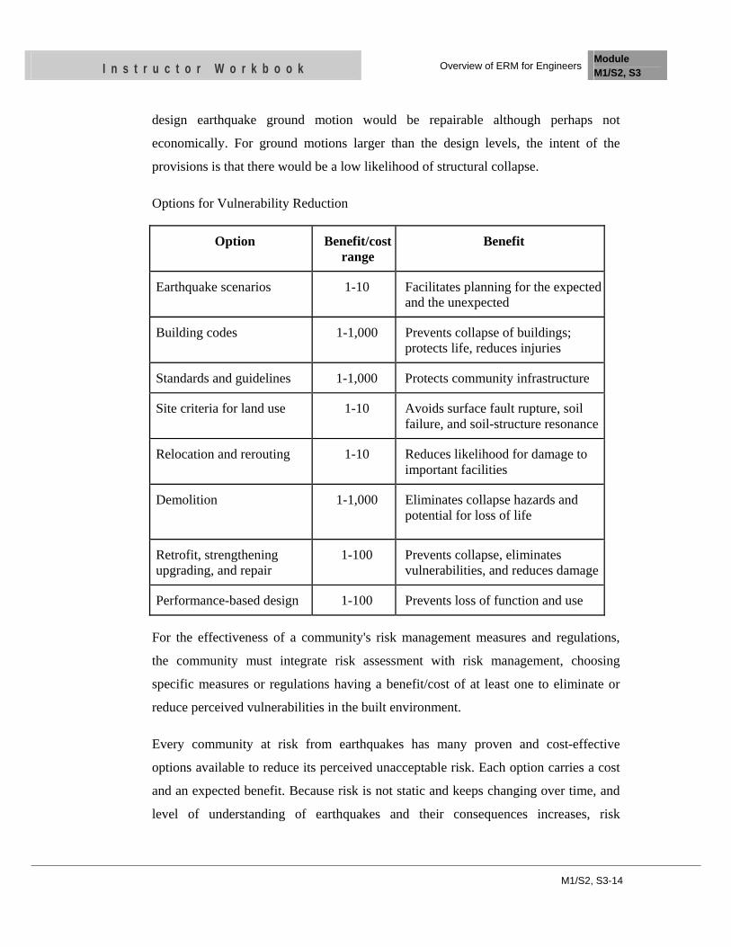
Options for Vulnerability Reduction
Option Benefit/cost range
Benefit
Earthquake scenarios 1-10 Facilitates planning for the expected and the unexpected
Building codes 1-1,000 Prevents collapse of buildings; protects life, reduces injuries
Standards and guidelines 1-1,000 Protects community infrastructure
Site criteria for land use 1-10 Avoids surface fault rupture, soil failure, and soil-structure resonance
Relocation and rerouting 1-10 Reduces likelihood for damage to important facilities
Demolition 1-1,000 Eliminates collapse hazards and potential for loss of life
Retrofit, strengthening upgrading, and repair
1-100 Prevents collapse, eliminates vulnerabilities, and reduces damage
Performance-based design 1-100 Prevents loss of function and use
For the effectiveness of a community's risk management measures and regulations,
the community must integrate risk assessment with risk management, choosing
specific measures or regulations having a benefit/cost of at least one to eliminate or
reduce perceived vulnerabilities in the built environment.
Every community at risk from earthquakes has many proven and cost-effective
options available to reduce its perceived unacceptable risk. Each option carries a cost
and an expected benefit. Because risk is not static and keeps changing over time, and
level of understanding of earthquakes and their consequences increases, risk
M1/S2, S3-15
I n s t r u c t o r W o r k b o o k Overview of ERM for Engineers Module M1/S2, S3
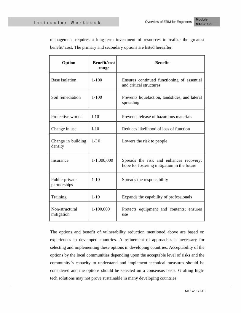
management requires a long-term investment of resources to realize the greatest
benefit/ cost. The primary and secondary options are listed hereafter.
The options and benefit of vulnerability reduction mentioned above are based on
experiences in developed countries. A refinement of approaches is necessary for
selecting and implementing these options in developing countries. Acceptability of the
options by the local communities depending upon the acceptable level of risks and the
community’s capacity to understand and implement technical measures should be
considered and the options should be selected on a consensus basis. Grafting high-
tech solutions may not prove sustainable in many developing countries.
Option Benefit/cost range
Benefit
Base isolation 1-100 Ensures continued functioning of essential and critical structures
Soil remediation 1-100 Prevents liquefaction, landslides, and lateral spreading
Protective works I-10 Prevents release of hazardous materials
Change in use I-10 Reduces likelihood of loss of function
Change in building density
1-I 0 Lowers the risk to people
Insurance 1-1,000,000 Spreads the risk and enhances recovery; hope for fostering mitigation in the future
Public-private partnerships
1-10 Spreads the responsibility
Training 1-10 Expands the capability of professionals
Non-structural mitigation
1-100,000 Protects equipment and contents; ensures use
M1/S2, S3-16
I n s t r u c t o r W o r k b o o k Overview of ERM for Engineers Module M1/S2, S3
UNIT TEST
1. Name the steps carried out for a risk management plan
1. …
2. …
3. ….
• ….
• …..
• ….
4. ….
5. …..
6. ….
7. ……
2. Write three implementation strategies to achieve the goal of seismic safety.
1. …..
2. …..
3. …..
OBJECTIVES
As a result of this session, you should be able to:
• Be familiar with the notable earthquake in the history
• Be familiar with the historical earthquake of Nepal
Instructor Workbook Module M1/S4
Experiences of Past Earthquake

CONTENTS
1 Some Notable earthquakes in the history ...................................................... 2
1.1 Lisbon, Portugal, November 1, 1755 ........................................................ 3
1.2 San Francisco, California, April 18, 1906 ................................................ 3
1.3 Kansu, China, December 16, 1920 ........................................................... 4
1.4 Tokyo-Yokohama, Japan, September 1, 1923 .......................................... 4
1.5 Agadir, Morocco, January 13, 1960 ......................................................... 4
1.6 Tangshan, China, July 27, 1976 ................................................................ 5
1.7 Mexico City, Mexico September 19, 1985 ............................................... 5
1.8 Armenia, USSR, December 7, 1988 ......................................................... 6
1.9 Northridge (Los Angeles), California, January 17, 1994 ......................... 6
1.10 Kobe, Japan, January 16, 1995 ................................................................. 7
1.11 Gölcük,Turkey, August 17, 1999 .............................................................. 7
1.12 Nanaou, Taiwan, September 20, 1999 ...................................................... 7
2 Historical Earthquakes of Nepal ..................................................................... 8

M1/S4- 2
I n s t r u c t o r W o r k b o o k Experiences of Past Earthquake Module M1/S4
1 SOME NOTABLE EARTHQUAKES IN THE HISTORY
We have been familiar that earthquake occurs due to the plate tectonic mechanism. Past
experiences showed that most of the countries lying on the plate boundaries had suffered
from great earthquakes. The corresponding plate motions and underlying driving forces lead
to strong variations in seismic hazard throughout the region of plate boundaries. During the
last few years, the use of historical earthquake records has considerably increased. Since
these data offer the possibility to cover quite a long time window they can be used as relevant
resources for the evaluation of seismic hazard.
Earthquakes have been a part of myth and legend since dawn of mankind. However, it has been recorded as early as 1177 B.C. in China. The earliest seismologists were the Chinese who worked hard to record their quakes in detail.
In European history, the earliest recorded earthquake occurred in 580 B.C. In North America the great earthquakes of 1811-1812 occurred near New Madrid, Missouri. The magnitude of the quakes are not known, but they are estimated to have been about 8 on the Richter scale. The Chilean quake of 1960 was the biggest quake ever recorded. It came in at 9.5 on the Richter scale.
It is thought that some animals may feel vibrations from a quake before humans, and that even minutes before a quake dogs may howl and birds fly erratically. However, evidence for such sensitivity by animals is purely anecdotal.
Thousands of earthquakes occur every year around the world that is strong enough to be felt by people. Of these, only a few hundred are of sufficient size to produce significant damage, and fewer still are large enough to cause substantial damage. Below is a list of some of the most devastating earthquakes recorded around the world dating back to 1755.
Location Date Magnitude Casualties Lisbon, Portugal Nov 1, 1755 8.6 60,000 people killed San Francisco, California Apr 18, 1906 8.3 700 people killed Kansu, China Dec 16, 1920 8.5 200,000 people killed Tokyo-Yokohama, Japan Sep 1, 1923 8.3 143,000 people killed Agadir, Morocco Jan 13, 1960 5.9 12,500 people killed Tangshan, China Jul 27, 1976 8.0 255,000 people killed Mexico City, Mexico Sep 19, 1985 8.1 9,500 people killed

M1/S4- 3
I n s t r u c t o r W o r k b o o k Experiences of Past Earthquake Module M1/S4
Armenia, USSR Dec 7, 1988 6.8 25,000 people killed Loma Prieta, California Oct 17, 1989 7.0 62 people killed Northridge, California Jan 17, 1994 6.8 60 people killed Kobe, Japan Jan 16, 1995 6.8 5,530 people killed Gölcük, Turkey Aug 17, 1999 7.6 17,000 people killed Nantou, Taiwan Sep 20, 1999 7.6 1,800 people killed BengKulu, Indonesia Jun 4, 2000 7.9 N/A New Britain, PNG Nov 16, 2000 7.3 N/A India/ Pakistan Border Jan 26, 2001 7.9 20,000+ people killed Bam, Iran 2003 6.6 26,200 Sumatra, Indonesia 2004 9 >280,000 Pakistan 2005 Port-O-Prince, Haiti 2010 7.3 >240,000 Chile 2010 8.5 >1100
1.1 Lisbon, Portugal, November 1, 1755
Magnitude: 8.6; 60,000 people killed. Most of Lisbon's 250,000 inhabitants were at church for All Saints' Day when the first quake struck at 9:40 a.m. on November 1, 1755. It was followed by an even more powerful tremor, which sent buildings toppling down on the terrified populace. Huge waves generated by the quake crashed over the quays, drowning thousands and causing widespread damage. Fire raged through what was left of the city, burning for three days. Other countries also experienced a great deal of destruction in the Lisbon quake and associated tsunamis. For instance, approximately 10,000 people died in Morocco alone.
1.2 San Francisco, California, April 18, 1906
Magnitude 8.3; 700 people killed. Most of San Francisco lay in ruins after movement along 270 miles (430 kilometers) of California's San Andreas Fault generated an 8.3 magnitude earthquake. However, it was the post-quake fire, which swept through the city that caused most of the damage. This was the most destructive quake in U.S. history.
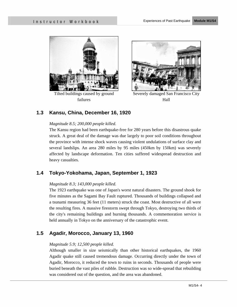
M1/S4- 4
I n s t r u c t o r W o r k b o o k Experiences of Past Earthquake Module M1/S4
Tilted buildings caused by ground failures
Severely damaged San Francisco City Hall
1.3 Kansu, China, December 16, 1920
Magnitude 8.5; 200,000 people killed. The Kansu region had been earthquake-free for 280 years before this disastrous quake struck. A great deal of the damage was due largely to poor soil conditions throughout the province with intense shock waves causing violent undulations of surface clay and several landslips. An area 280 miles by 95 miles (450km by 150km) was severely affected by landscape deformation. Ten cities suffered widespread destruction and heavy casualties.
1.4 Tokyo-Yokohama, Japan, September 1, 1923
Magnitude 8.3; 143,000 people killed. The 1923 earthquake was one of Japan's worst natural disasters. The ground shook for five minutes as the Sagami Bay Fault ruptured. Thousands of buildings collapsed and a tsunami measuring 36 feet (11 meters) struck the coast. Most destructive of all were the resulting fires. A massive firestorm swept through Tokyo, destroying two thirds of the city's remaining buildings and burning thousands. A commemoration service is held annually in Tokyo on the anniversary of the catastrophic event.
1.5 Agadir, Morocco, January 13, 1960
Magnitude 5.9; 12,500 people killed. Although smaller in size seismically than other historical earthquakes, the 1960 Agadir quake still caused tremendous damage. Occurring directly under the town of Agadir, Morocco, it reduced the town to ruins in seconds. Thousands of people were buried beneath the vast piles of rubble. Destruction was so wide-spread that rebuilding was considered out of the question, and the area was abandoned.
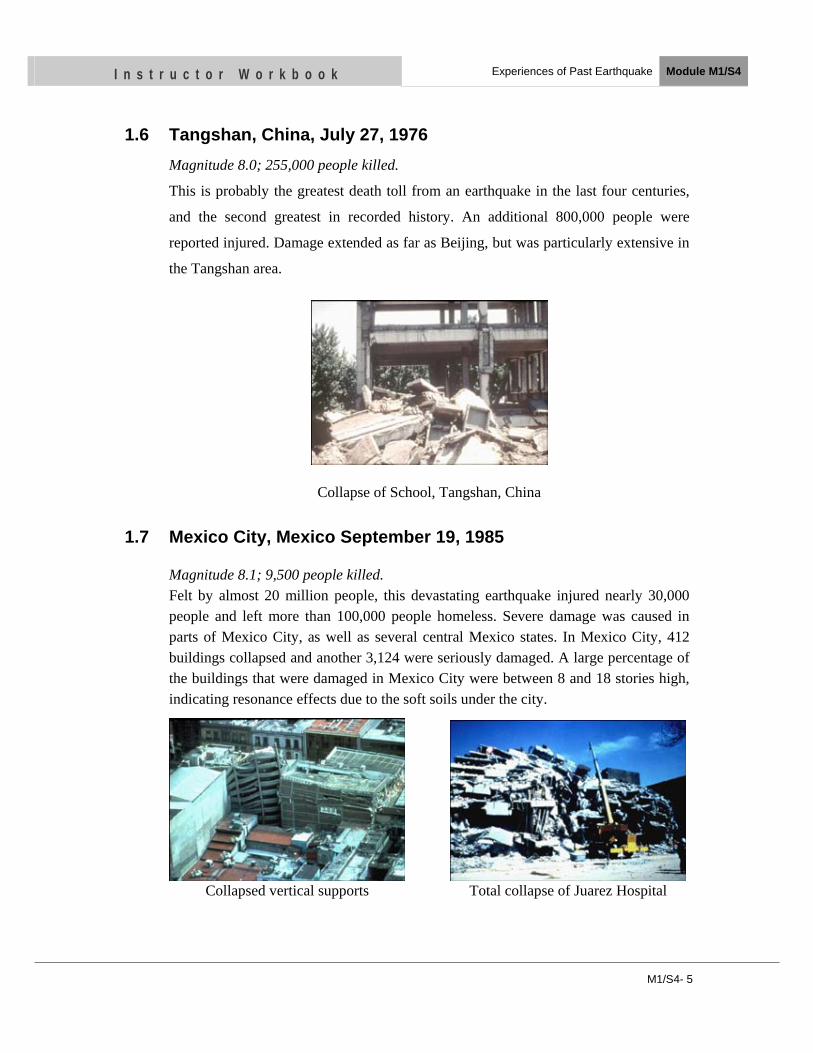
M1/S4- 5
I n s t r u c t o r W o r k b o o k Experiences of Past Earthquake Module M1/S4
1.6 Tangshan, China, July 27, 1976 Magnitude 8.0; 255,000 people killed.
This is probably the greatest death toll from an earthquake in the last four centuries,
and the second greatest in recorded history. An additional 800,000 people were
reported injured. Damage extended as far as Beijing, but was particularly extensive in
the Tangshan area.
Collapse of School, Tangshan, China
1.7 Mexico City, Mexico September 19, 1985
Magnitude 8.1; 9,500 people killed. Felt by almost 20 million people, this devastating earthquake injured nearly 30,000 people and left more than 100,000 people homeless. Severe damage was caused in parts of Mexico City, as well as several central Mexico states. In Mexico City, 412 buildings collapsed and another 3,124 were seriously damaged. A large percentage of the buildings that were damaged in Mexico City were between 8 and 18 stories high, indicating resonance effects due to the soft soils under the city.
Collapsed vertical supports Total collapse of Juarez Hospital
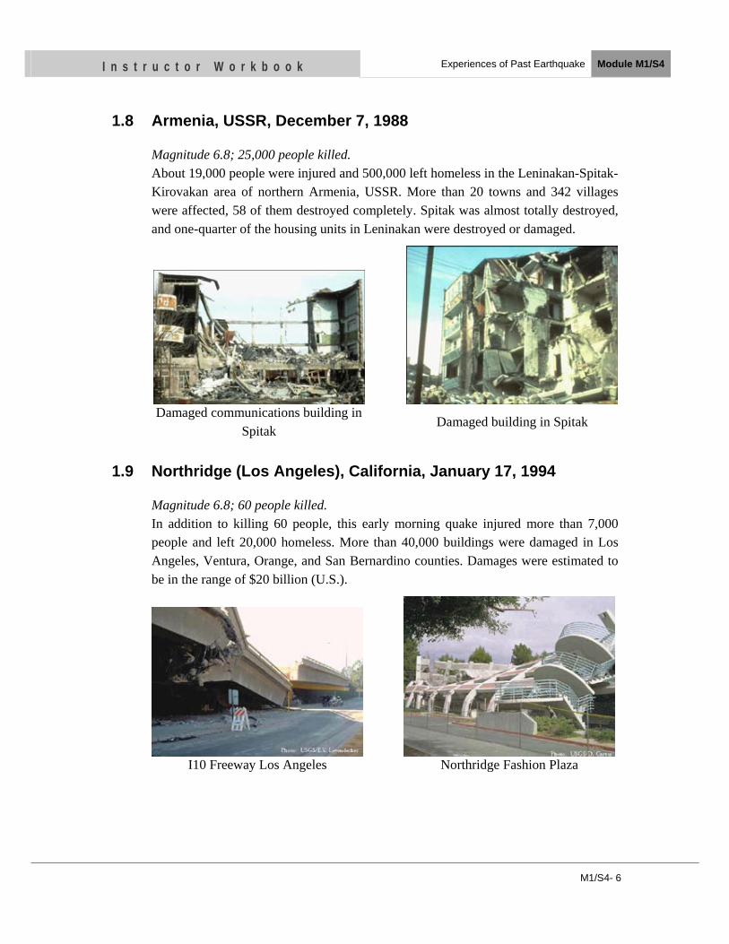
M1/S4- 6
I n s t r u c t o r W o r k b o o k Experiences of Past Earthquake Module M1/S4
1.8 Armenia, USSR, December 7, 1988
Magnitude 6.8; 25,000 people killed. About 19,000 people were injured and 500,000 left homeless in the Leninakan-Spitak-Kirovakan area of northern Armenia, USSR. More than 20 towns and 342 villages were affected, 58 of them destroyed completely. Spitak was almost totally destroyed, and one-quarter of the housing units in Leninakan were destroyed or damaged.
Damaged communications building in Spitak
Damaged building in Spitak
1.9 Northridge (Los Angeles), California, January 17, 1994
Magnitude 6.8; 60 people killed. In addition to killing 60 people, this early morning quake injured more than 7,000 people and left 20,000 homeless. More than 40,000 buildings were damaged in Los Angeles, Ventura, Orange, and San Bernardino counties. Damages were estimated to be in the range of $20 billion (U.S.).
I10 Freeway Los Angeles Northridge Fashion Plaza
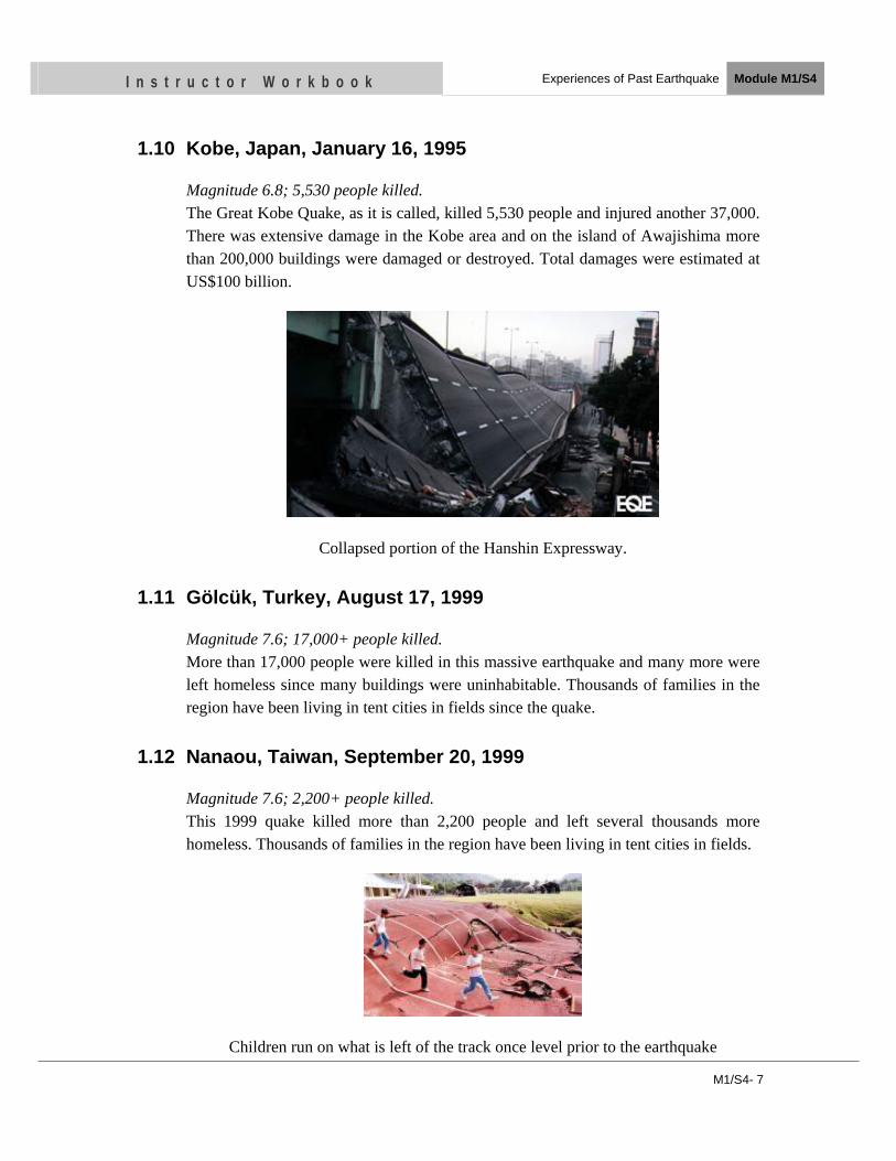
M1/S4- 7
I n s t r u c t o r W o r k b o o k Experiences of Past Earthquake Module M1/S4
1.10 Kobe, Japan, January 16, 1995
Magnitude 6.8; 5,530 people killed. The Great Kobe Quake, as it is called, killed 5,530 people and injured another 37,000. There was extensive damage in the Kobe area and on the island of Awajishima more than 200,000 buildings were damaged or destroyed. Total damages were estimated at US$100 billion.
Collapsed portion of the Hanshin Expressway.
1.11 Gölcük, Turkey, August 17, 1999
Magnitude 7.6; 17,000+ people killed. More than 17,000 people were killed in this massive earthquake and many more were left homeless since many buildings were uninhabitable. Thousands of families in the region have been living in tent cities in fields since the quake.
1.12 Nanaou, Taiwan, September 20, 1999
Magnitude 7.6; 2,200+ people killed. This 1999 quake killed more than 2,200 people and left several thousands more homeless. Thousands of families in the region have been living in tent cities in fields.
Children run on what is left of the track once level prior to the earthquake
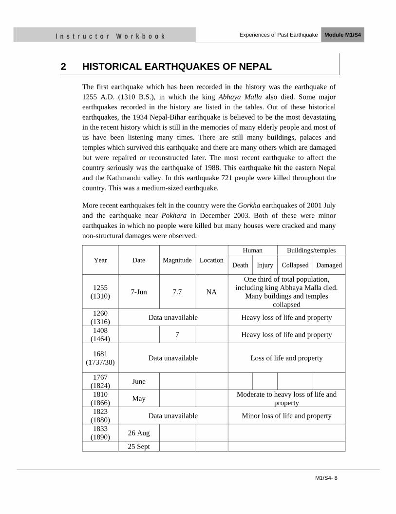
M1/S4- 8
I n s t r u c t o r W o r k b o o k Experiences of Past Earthquake Module M1/S4
2 HISTORICAL EARTHQUAKES OF NEPAL
The first earthquake which has been recorded in the history was the earthquake of 1255 A.D. (1310 B.S.), in which the king Abhaya Malla also died. Some major earthquakes recorded in the history are listed in the tables. Out of these historical earthquakes, the 1934 Nepal-Bihar earthquake is believed to be the most devastating in the recent history which is still in the memories of many elderly people and most of us have been listening many times. There are still many buildings, palaces and temples which survived this earthquake and there are many others which are damaged but were repaired or reconstructed later. The most recent earthquake to affect the country seriously was the earthquake of 1988. This earthquake hit the eastern Nepal and the Kathmandu valley. In this earthquake 721 people were killed throughout the country. This was a medium-sized earthquake.
More recent earthquakes felt in the country were the Gorkha earthquakes of 2001 July and the earthquake near Pokhara in December 2003. Both of these were minor earthquakes in which no people were killed but many houses were cracked and many non-structural damages were observed.
Year Date Magnitude Location Human Buildings/temples
Death Injury Collapsed Damaged
1255 (1310) 7-Jun 7.7 NA
One third of total population, including king Abhaya Malla died.
Many buildings and temples collapsed
1260 (1316) Data unavailable Heavy loss of life and property
1408 (1464) 7 Heavy loss of life and property
1681 (1737/38) Data unavailable Loss of life and property
1767 (1824) June
1810 (1866) May Moderate to heavy loss of life and
property 1823
(1880) Data unavailable Minor loss of life and property
1833 (1890) 26 Aug
25 Sept
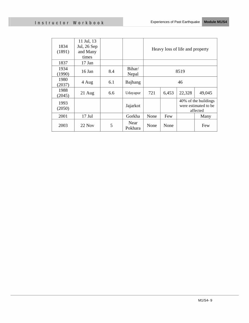
M1/S4- 9
I n s t r u c t o r W o r k b o o k Experiences of Past Earthquake Module M1/S4
1834 (1891)
11 Jul, 13 Jul, 26 Sep and Many
times
Heavy loss of life and property
1837 17 Jan 1934
(1990) 16 Jan 8.4 Bihar/ Nepal 8519
1980 (2037) 4 Aug 6.1 Bajhang 46
1988 (2045) 21 Aug 6.6 Udayapur 721 6,453 22,328 49,045
1993 (2050) Jajarkot
40% of the buildings were estimated to be
affected2001 17 Jul Gorkha None Few Many
2003 22 Nov 5 Near Pokhara None None Few
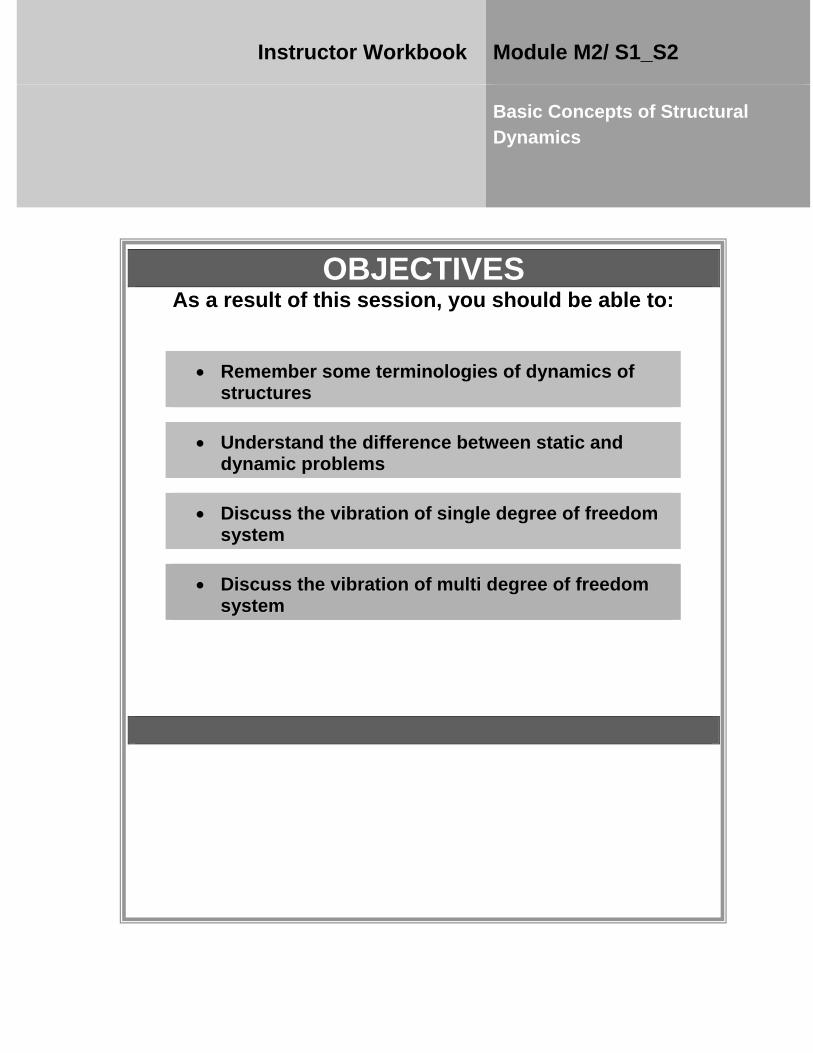
OBJECTIVES As a result of this session, you should be able to:
•• RReemmeemmbbeerr ssoommee tteerrmmiinnoollooggiieess ooff ddyynnaammiiccss ooff ssttrruuccttuurreess
• UUnnddeerrssttaanndd tthhee ddiiffffeerreennccee bbeettwweeeenn ssttaattiicc aanndd ddyynnaammiicc pprroobblleemmss
• DDiissccuussss tthhee vviibbrraattiioonn ooff ssiinnggllee ddeeggrreeee ooff ffrreeeeddoomm ssyysstteemm
•• DDiissccuussss tthhee vviibbrraattiioonn ooff mmuullttii ddeeggrreeee ooff ffrreeeeddoomm ssyysstteemm
Instructor Workbook Module M2/ S1_S2
Basic Concepts of Structural Dynamics
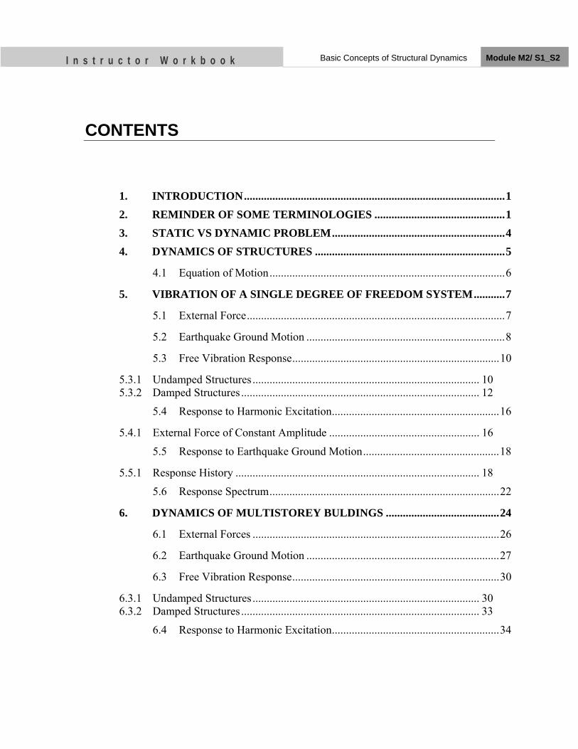
I n s t r u c t o r W o r k b o o k Basic Concepts of Structural Dynamics Module M2/ S1_S2
CONTENTS
1. INTRODUCTION ............................................................................................ 1 2. REMINDER OF SOME TERMINOLOGIES .............................................. 1 3. STATIC VS DYNAMIC PROBLEM ............................................................. 4 4. DYNAMICS OF STRUCTURES ................................................................... 5
4.1 Equation of Motion ................................................................................... 6
5. VIBRATION OF A SINGLE DEGREE OF FREEDOM SYSTEM ........... 7
5.1 External Force ........................................................................................... 7
5.2 Earthquake Ground Motion ...................................................................... 8
5.3 Free Vibration Response ......................................................................... 10
5.3.1 Undamped Structures ................................................................................ 10 5.3.2 Damped Structures .................................................................................... 12
5.4 Response to Harmonic Excitation ........................................................... 16
5.4.1 External Force of Constant Amplitude ..................................................... 16
5.5 Response to Earthquake Ground Motion ................................................ 18
5.5.1 Response History ...................................................................................... 18
5.6 Response Spectrum ................................................................................. 22
6. DYNAMICS OF MULTISTOREY BULDINGS ........................................ 24
6.1 External Forces ....................................................................................... 26
6.2 Earthquake Ground Motion .................................................................... 27
6.3 Free Vibration Response ......................................................................... 30
6.3.1 Undamped Structures ................................................................................ 30 6.3.2 Damped Structures .................................................................................... 33
6.4 Response to Harmonic Excitation ........................................................... 34
I n s t r u c t o r W o r k b o o k Basic Concepts of Structural Dynamics Module M2/ S1_S2
M2/S1_S2 - 1
1. INTRODUCTION
The dynamic behavior of structures is an important topic in many fields. Aerospace engineers must understand aero-dynamics to simulate space vehicles and airplanes, while mechanical engineers must understand dynamics to isolate or control the vibration of machinery. In civil engineering, an understanding of structural dynamics is important in the design and retrofit of structures that need to withstand severe dynamic loading from earthquakes, hurricanes, and strong winds, or to identify the occurrence and location of damage within an existing structure.
The earthquake loading is dynamic in nature and the analysis of structure due to earthquake is one of the important steps in the structural design procedure. Computation of earthquake loading in the equivalent static analysis is based on certain dynamic analysis of structure. Therefore, a preliminary exposure to structural dynamics is required for better understanding of the earthquake engineering. 2. REMINDER OF SOME TERMINOLOGIES Some of the terms frequently used are explained below. Degree of freedom - The number of degrees of freedom is defined as the minimum number of variables that are required for a full description of the movement of a structure. A system is said to have n degrees of freedom if its orientation during vibration is defined by n independent coordinates. A spring supported mass which moves in only one direction without rotation has one degree of freedom. A single storey frame vibrating in its plane horizontally is another example of a system having one degree of freedom. For example, for the single storey building shown in Fig. 1 we assume the floor is rigid as compared to the two columns. Thus, the displacement of the structure is completely described by the displacement x of the floor. Similarly, the building shown in Fig. 2 has two degrees of freedom because we need to describe the movement of each floor separately in order to describe the movement of the whole structure.
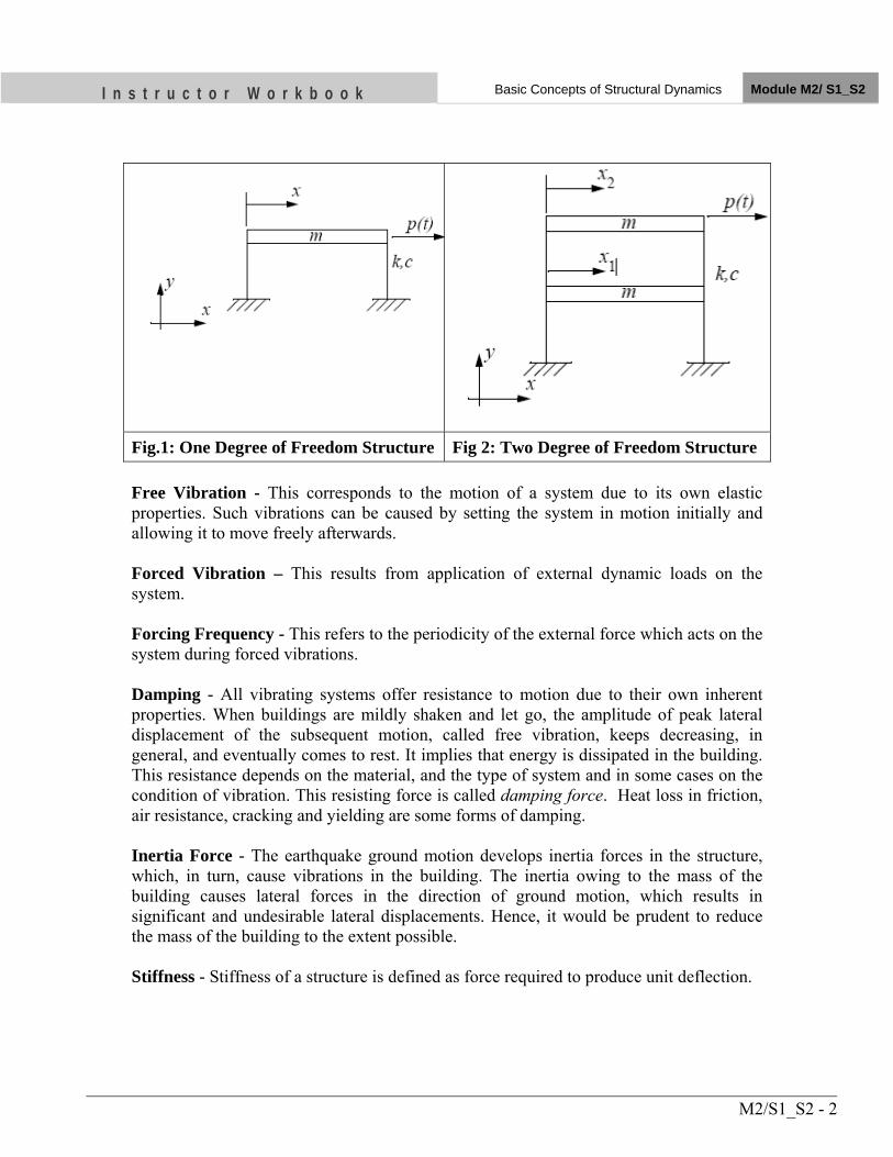
I n s t r u c t o r W o r k b o o k Basic Concepts of Structural Dynamics Module M2/ S1_S2
M2/S1_S2 - 2
Fig.1: One Degree of Freedom Structure Fig 2: Two Degree of Freedom Structure Free Vibration - This corresponds to the motion of a system due to its own elastic properties. Such vibrations can be caused by setting the system in motion initially and allowing it to move freely afterwards. Forced Vibration – This results from application of external dynamic loads on the system. Forcing Frequency - This refers to the periodicity of the external force which acts on the system during forced vibrations. Damping - All vibrating systems offer resistance to motion due to their own inherent properties. When buildings are mildly shaken and let go, the amplitude of peak lateral displacement of the subsequent motion, called free vibration, keeps decreasing, in general, and eventually comes to rest. It implies that energy is dissipated in the building. This resistance depends on the material, and the type of system and in some cases on the condition of vibration. This resisting force is called damping force. Heat loss in friction, air resistance, cracking and yielding are some forms of damping. Inertia Force - The earthquake ground motion develops inertia forces in the structure, which, in turn, cause vibrations in the building. The inertia owing to the mass of the building causes lateral forces in the direction of ground motion, which results in significant and undesirable lateral displacements. Hence, it would be prudent to reduce the mass of the building to the extent possible. Stiffness - Stiffness of a structure is defined as force required to produce unit deflection.
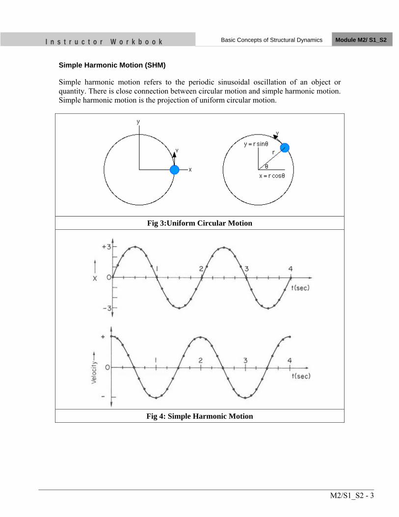
I n s t r u c t o r W o r k b o o k Basic Concepts of Structural Dynamics Module M2/ S1_S2
M2/S1_S2 - 3
Simple Harmonic Motion (SHM) Simple harmonic motion refers to the periodic sinusoidal oscillation of an object or quantity. There is close connection between circular motion and simple harmonic motion. Simple harmonic motion is the projection of uniform circular motion.
Fig 3:Uniform Circular Motion
Fig 4: Simple Harmonic Motion
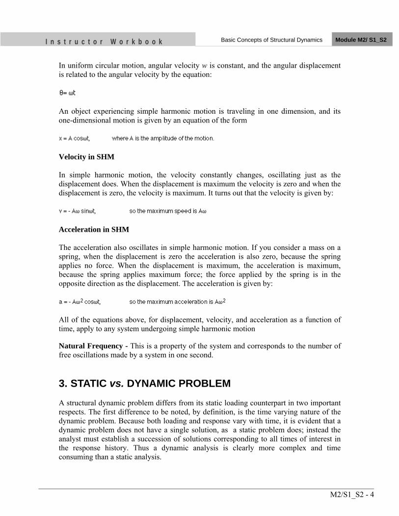
I n s t r u c t o r W o r k b o o k Basic Concepts of Structural Dynamics Module M2/ S1_S2
M2/S1_S2 - 4
In uniform circular motion, angular velocity w is constant, and the angular displacement is related to the angular velocity by the equation:
An object experiencing simple harmonic motion is traveling in one dimension, and its one-dimensional motion is given by an equation of the form
Velocity in SHM
In simple harmonic motion, the velocity constantly changes, oscillating just as the displacement does. When the displacement is maximum the velocity is zero and when the displacement is zero, the velocity is maximum. It turns out that the velocity is given by:
Acceleration in SHM
The acceleration also oscillates in simple harmonic motion. If you consider a mass on a spring, when the displacement is zero the acceleration is also zero, because the spring applies no force. When the displacement is maximum, the acceleration is maximum, because the spring applies maximum force; the force applied by the spring is in the opposite direction as the displacement. The acceleration is given by:
All of the equations above, for displacement, velocity, and acceleration as a function of time, apply to any system undergoing simple harmonic motion Natural Frequency - This is a property of the system and corresponds to the number of free oscillations made by a system in one second. 3. STATIC vs. DYNAMIC PROBLEM A structural dynamic problem differs from its static loading counterpart in two important respects. The first difference to be noted, by definition, is the time varying nature of the dynamic problem. Because both loading and response vary with time, it is evident that a dynamic problem does not have a single solution, as a static problem does; instead the analyst must establish a succession of solutions corresponding to all times of interest in the response history. Thus a dynamic analysis is clearly more complex and time consuming than a static analysis.
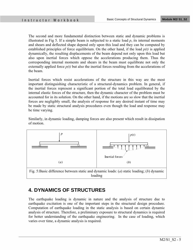
I n s t r u c t o r W o r k b o o k Basic Concepts of Structural Dynamics Module M2/ S1_S2
M2/S1_S2 - 5
The second and more fundamental distinction between static and dynamic problems is illustrated in Fig 5. If a simple beam is subjected to a static load p, its internal moments and shears and deflected shape depend only upon this load and they can be computed by established principles of force equilibrium. On the other hand, if the load p(t) is applied dynamically, the resulting displacements of the beam depend not only upon this load but also upon inertial forces which oppose the accelerations producing them. Thus the corresponding internal moments and shears in the beam must equilibrate not only the externally applied force p(t) but also the inertial forces resulting from the accelerations of the beam. Inertial forces which resist accelerations of the structure in this way are the most important distinguishing characteristic of a structural-dynamics problem. In general, if the inertial forces represent a significant portion of the total load equilibrated by the internal elastic forces of the structure, then the dynamic character of the problem must be accounted for in its solution. On the other hand, if the motions are so slow that the inertial forces are negligibly small, the analysis of response for any desired instant of time may be made by static structural analysis procedures even though the load and response may be time varying. Similarly, in dynamic loading, damping forces are also present which result in dissipation of motion.
Fig. 5:Basic difference between static and dynamic loads: (a) static loading; (b) dynamic
loading 4. DYNAMICS OF STRUCTURES The earthquake loading is dynamic in nature and the analysis of structure due to earthquake excitation is one of the important steps in the structural design procedure. Computation of earthquake loading in the static analysis is based on certain dynamic analysis of structure. Therefore, a preliminary exposure to structural dynamics is required for better understanding of the earthquake engineering. In the case of loading, which varies over time, a dynamic analysis is required.
I n s t r u c t o r W o r k b o o k Basic Concepts of Structural Dynamics Module M2/ S1_S2
M2/S1_S2 - 6
4.1 Equation of Motion
The primary objective of a deterministic structural dynamic analysis is the evaluation of the displacement time-histories of a given structure subjected to a given time-varying loading. In most cases, an approximate analysis involving only a limited number of degrees of freedom will provide sufficient accuracy; thus, the problem can be reduced to the determination of the time-histories of these selected displacement components. The mathematical expressions defining the dynamic displacements are called the equations of motion of the structure, and the solution of these equations of motion provides the required displacement time-histories. The idealized structure shown in Fig.6a is the simple structural system to understand the dynamics of structures. The idealized structure is in dynamic equilibrium at any time. This equilibrium is between the applied external force f and the internal forces of the structure, namely inertia force fI which resist acceleration, damping force fD which resist velocities and stiffness force fS which oppose displacement. Mathematically, fI +fD + fS = f(t) or, in terms of structural properties m ü (t) + c ů (t) + k u(t) = f(t) which is the equation of motion of the mass. ü (t), ů(t) and u(t) are acceleration, velocity and displacement respectively, of the mass measured with respect to the ground. In the above equation, the mass element m and the stiffness element k are key parameters in the dynamic analysis. But the damping element c, and the excitation f(t) are also the governing factors in the analysis. When a system is vibrating in absence of external excitation, it is called free vibration. When the system is considered ignoring damping and without external excitation, it is called undamped free vibration. So the vibration of a structure can be classified as (a) Without loading, i.e. free vibration and (b) With loading, i.e. forced vibration. Considering the presence of damping element, the system can be classified in the following four categories:
(a) Undamped free vibration (b) Damped free vibration (c) Undamped forced vibration (d) Damped forced vibration.
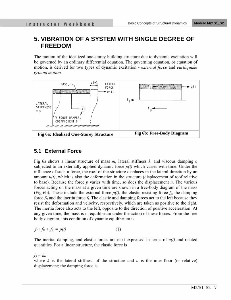
I n s t r u c t o r W o r k b o o k Basic Concepts of Structural Dynamics Module M2/ S1_S2
M2/S1_S2 - 7
5. VIBRATION OF A SYSTEM WITH SINGLE DEGREE OF FREEDOM
The motion of the idealized one-storey building structure due to dynamic excitation will be governed by an ordinary differential equation. The governing equation, or equation of motion, is derived for two types of dynamic excitation - external force and earthquake ground motion.
Fig 6a: Idealized One-Storey Structure Fig 6b: Free-Body Diagram
5.1 External Force
Fig 6a shows a linear structure of mass m, lateral stiffness k, and viscous damping c subjected to an externally applied dynamic force p(t) which varies with time. Under the influence of such a force, the roof of the structure displaces in the lateral direction by an amount u(t), which is also the deformation in the structure (displacement of roof relative to base). Because the force p varies with time, so does the displacement u. The various forces acting on the mass at a given time are shown in a free-body diagram of the mass (Fig 6b). These include the external force p(t), the elastic resisting force fs, the damping force fD and the inertia force fI. The elastic and damping forces act to the left because they resist the deformation and velocity, respectively, which are taken as positive to the right. The inertia force also acts to the left, opposite to the direction of positive acceleration. At any given time, the mass is in equilibrium under the action of these forces. From the free body diagram, this condition of dynamic equilibrium is fI +fD + fS = p(t) (1) The inertia, damping, and elastic forces are next expressed in terms of u(t) and related quantities. For a linear structure, the elastic force is fS = ku where k is the lateral stiffness of the structure and u is the inter-floor (or relative) displacement; the damping force is
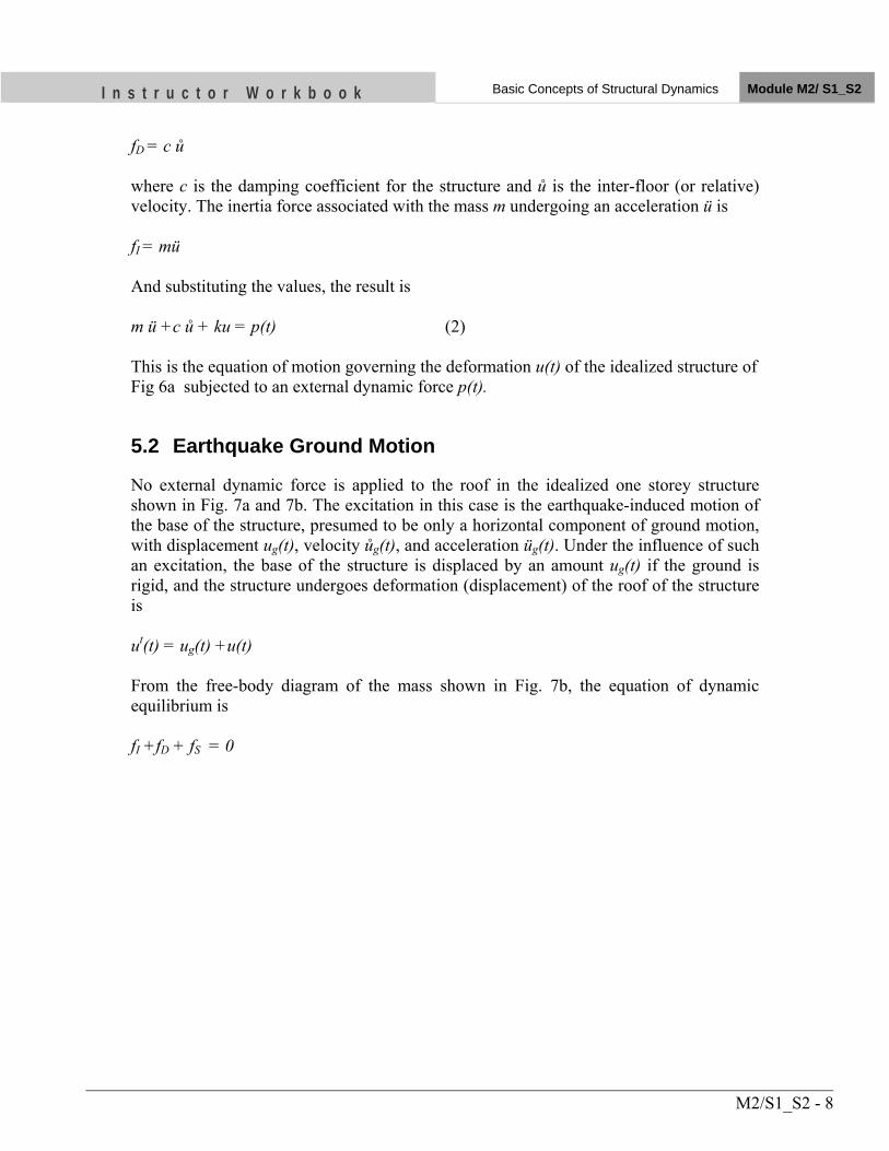
I n s t r u c t o r W o r k b o o k Basic Concepts of Structural Dynamics Module M2/ S1_S2
M2/S1_S2 - 8
fD = c ů where c is the damping coefficient for the structure and ů is the inter-floor (or relative) velocity. The inertia force associated with the mass m undergoing an acceleration ü is fI = mü And substituting the values, the result is m ü +c ů + ku = p(t) (2) This is the equation of motion governing the deformation u(t) of the idealized structure of Fig 6a subjected to an external dynamic force p(t).
5.2 Earthquake Ground Motion
No external dynamic force is applied to the roof in the idealized one storey structure shown in Fig. 7a and 7b. The excitation in this case is the earthquake-induced motion of the base of the structure, presumed to be only a horizontal component of ground motion, with displacement ug(t), velocity ůg(t), and acceleration üg(t). Under the influence of such an excitation, the base of the structure is displaced by an amount ug(t) if the ground is rigid, and the structure undergoes deformation (displacement) of the roof of the structure is ut(t) = ug(t) +u(t) From the free-body diagram of the mass shown in Fig. 7b, the equation of dynamic equilibrium is fI +fD + fS = 0
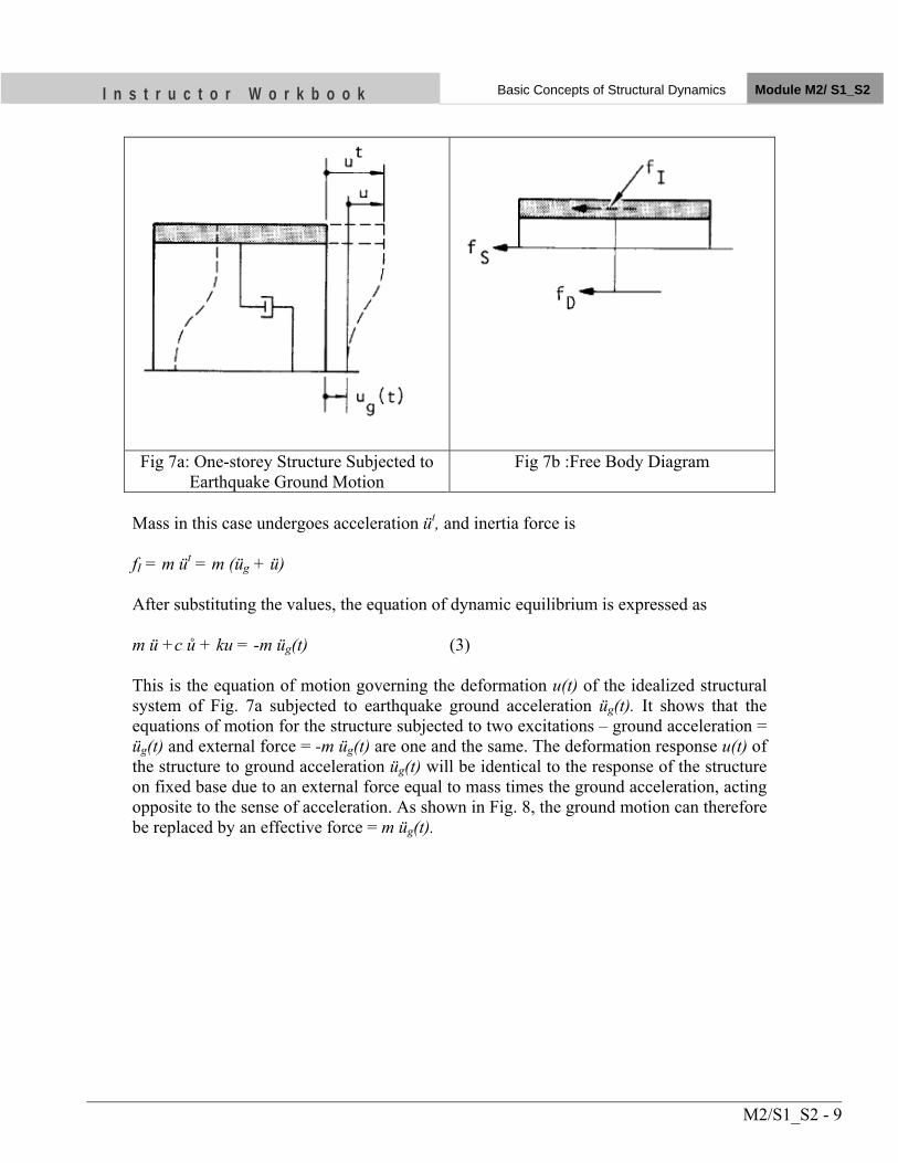
I n s t r u c t o r W o r k b o o k Basic Concepts of Structural Dynamics Module M2/ S1_S2
M2/S1_S2 - 9
Fig 7a: One-storey Structure Subjected to Earthquake Ground Motion
Fig 7b :Free Body Diagram
Mass in this case undergoes acceleration üt, and inertia force is fI = m üt = m (üg + ü) After substituting the values, the equation of dynamic equilibrium is expressed as m ü +c ů + ku = -m üg(t) (3) This is the equation of motion governing the deformation u(t) of the idealized structural system of Fig. 7a subjected to earthquake ground acceleration üg(t). It shows that the equations of motion for the structure subjected to two excitations – ground acceleration = üg(t) and external force = -m üg(t) are one and the same. The deformation response u(t) of the structure to ground acceleration üg(t) will be identical to the response of the structure on fixed base due to an external force equal to mass times the ground acceleration, acting opposite to the sense of acceleration. As shown in Fig. 8, the ground motion can therefore be replaced by an effective force = m üg(t).
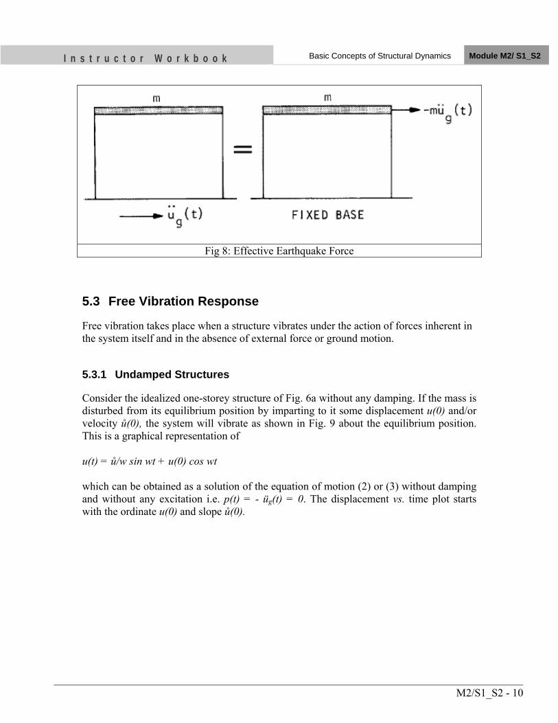
I n s t r u c t o r W o r k b o o k Basic Concepts of Structural Dynamics Module M2/ S1_S2
M2/S1_S2 - 10
Fig 8: Effective Earthquake Force
5.3 Free Vibration Response
Free vibration takes place when a structure vibrates under the action of forces inherent in the system itself and in the absence of external force or ground motion.
5.3.1 Undamped Structures
Consider the idealized one-storey structure of Fig. 6a without any damping. If the mass is disturbed from its equilibrium position by imparting to it some displacement u(0) and/or velocity ů(0), the system will vibrate as shown in Fig. 9 about the equilibrium position. This is a graphical representation of u(t) = ů/w sin wt + u(0) cos wt which can be obtained as a solution of the equation of motion (2) or (3) without damping and without any excitation i.e. p(t) = - üg(t) = 0. The displacement vs. time plot starts with the ordinate u(0) and slope ů(0).
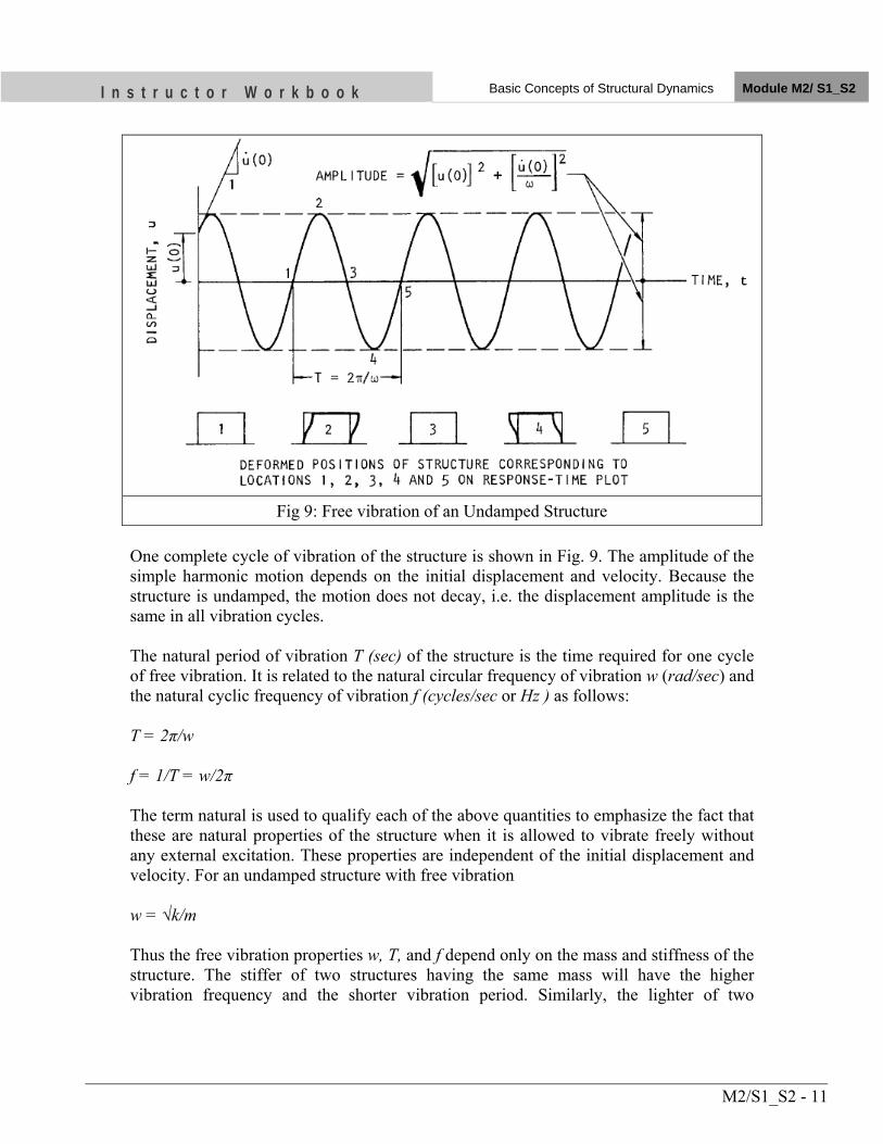
I n s t r u c t o r W o r k b o o k Basic Concepts of Structural Dynamics Module M2/ S1_S2
M2/S1_S2 - 11
Fig 9: Free vibration of an Undamped Structure One complete cycle of vibration of the structure is shown in Fig. 9. The amplitude of the simple harmonic motion depends on the initial displacement and velocity. Because the structure is undamped, the motion does not decay, i.e. the displacement amplitude is the same in all vibration cycles. The natural period of vibration T (sec) of the structure is the time required for one cycle of free vibration. It is related to the natural circular frequency of vibration w (rad/sec) and the natural cyclic frequency of vibration f (cycles/sec or Hz ) as follows: T = 2π/w f = 1/T = w/2π The term natural is used to qualify each of the above quantities to emphasize the fact that these are natural properties of the structure when it is allowed to vibrate freely without any external excitation. These properties are independent of the initial displacement and velocity. For an undamped structure with free vibration w = √k/m Thus the free vibration properties w, T, and f depend only on the mass and stiffness of the structure. The stiffer of two structures having the same mass will have the higher vibration frequency and the shorter vibration period. Similarly, the lighter of two
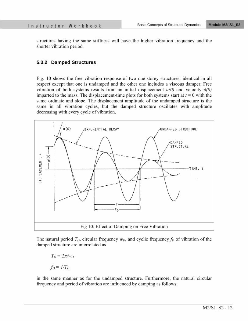
I n s t r u c t o r W o r k b o o k Basic Concepts of Structural Dynamics Module M2/ S1_S2
M2/S1_S2 - 12
structures having the same stiffness will have the higher vibration frequency and the shorter vibration period.
5.3.2 Damped Structures
Fig. 10 shows the free vibration response of two one-storey structures, identical in all respect except that one is undamped and the other one includes a viscous damper. Free vibration of both systems results from an initial displacement u(0) and velocity ů(0) imparted to the mass. The displacement-time plots for both systems start at t = 0 with the same ordinate and slope. The displacement amplitude of the undamped structure is the same in all vibration cycles, but the damped structure oscillates with amplitude decreasing with every cycle of vibration.
Fig 10: Effect of Damping on Free Vibration The natural period TD, circular frequency wD, and cyclic frequency fD of vibration of the damped structure are interrelated as TD = 2π/wD fD = 1/TD in the same manner as for the undamped structure. Furthermore, the natural circular frequency and period of vibration are influenced by damping as follows:
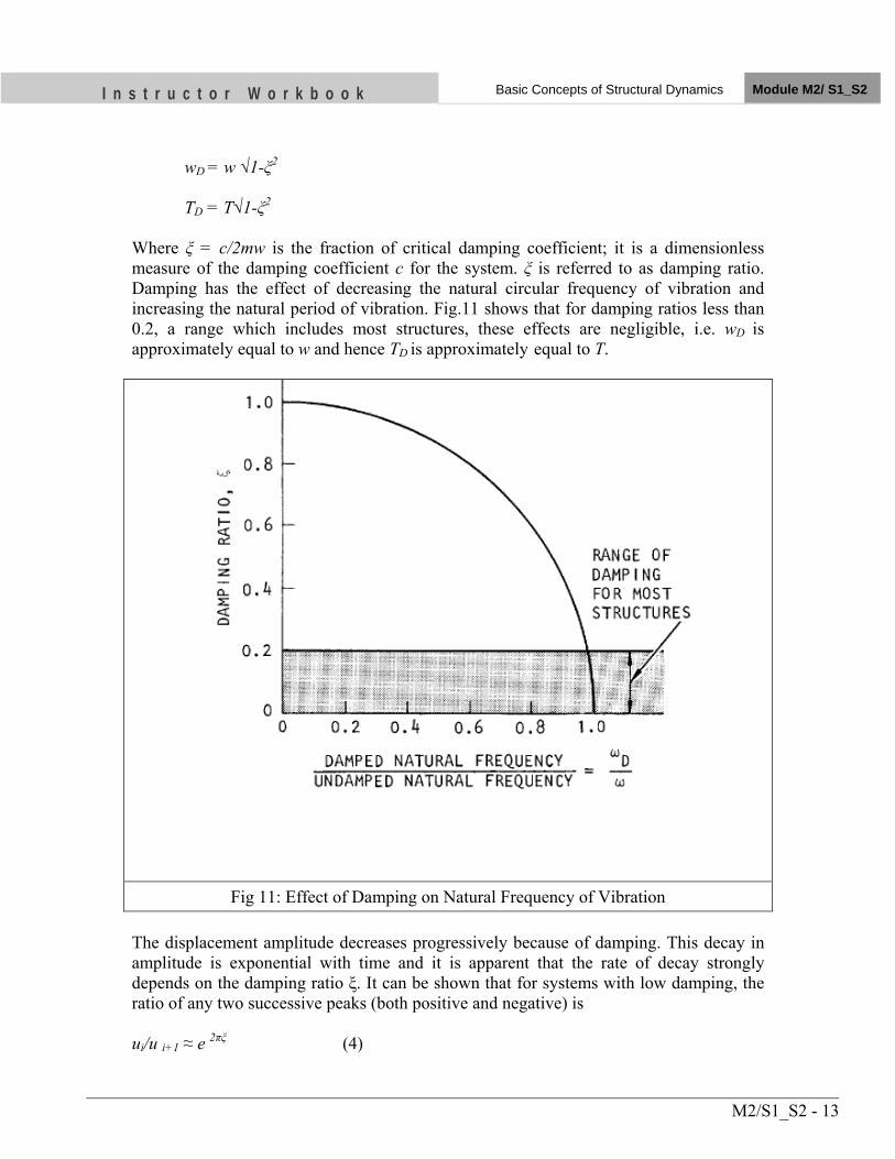
I n s t r u c t o r W o r k b o o k Basic Concepts of Structural Dynamics Module M2/ S1_S2
M2/S1_S2 - 13
wD = w √1-ξ2
TD = T√1-ξ2
Where ξ = c/2mw is the fraction of critical damping coefficient; it is a dimensionless measure of the damping coefficient c for the system. ξ is referred to as damping ratio. Damping has the effect of decreasing the natural circular frequency of vibration and increasing the natural period of vibration. Fig.11 shows that for damping ratios less than 0.2, a range which includes most structures, these effects are negligible, i.e. wD is approximately equal to w and hence TD is approximately equal to T.
Fig 11: Effect of Damping on Natural Frequency of Vibration The displacement amplitude decreases progressively because of damping. This decay in amplitude is exponential with time and it is apparent that the rate of decay strongly depends on the damping ratio ξ. It can be shown that for systems with low damping, the ratio of any two successive peaks (both positive and negative) is ui/u i+1 ≈ e 2πξ (4)
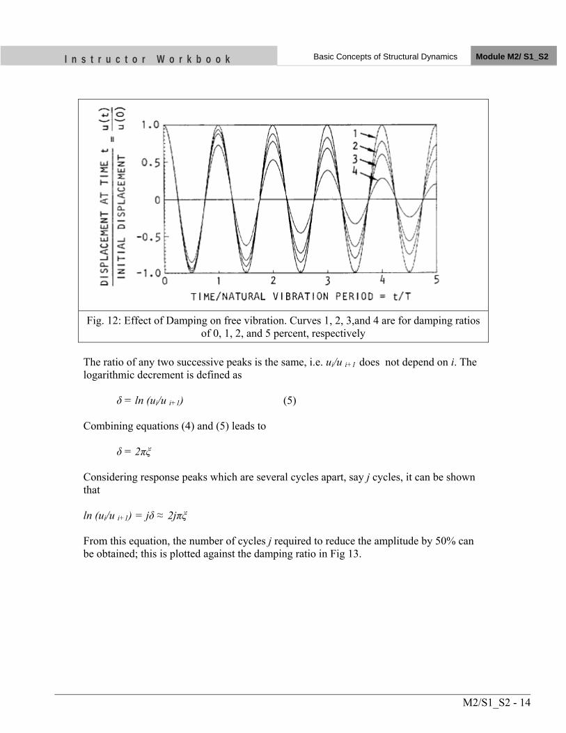
I n s t r u c t o r W o r k b o o k Basic Concepts of Structural Dynamics Module M2/ S1_S2
M2/S1_S2 - 14
Fig. 12: Effect of Damping on free vibration. Curves 1, 2, 3,and 4 are for damping ratios
of 0, 1, 2, and 5 percent, respectively The ratio of any two successive peaks is the same, i.e. ui/u i+1 does not depend on i. The logarithmic decrement is defined as δ = ln (ui/u i+1) (5) Combining equations (4) and (5) leads to δ = 2πξ Considering response peaks which are several cycles apart, say j cycles, it can be shown that ln (ui/u i+1) = jδ ≈ 2jπξ From this equation, the number of cycles j required to reduce the amplitude by 50% can be obtained; this is plotted against the damping ratio in Fig 13.
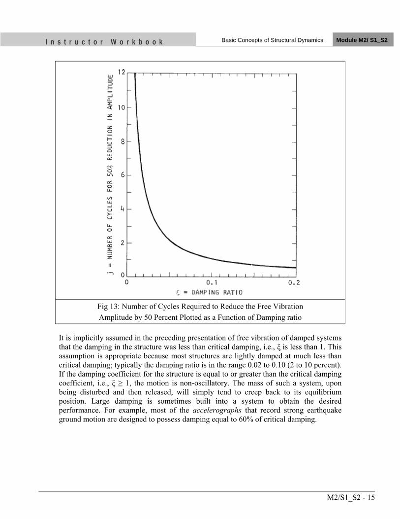
I n s t r u c t o r W o r k b o o k Basic Concepts of Structural Dynamics Module M2/ S1_S2
M2/S1_S2 - 15
Fig 13: Number of Cycles Required to Reduce the Free Vibration Amplitude by 50 Percent Plotted as a Function of Damping ratio
It is implicitly assumed in the preceding presentation of free vibration of damped systems that the damping in the structure was less than critical damping, i.e., ξ is less than 1. This assumption is appropriate because most structures are lightly damped at much less than critical damping; typically the damping ratio is in the range 0.02 to 0.10 (2 to 10 percent). If the damping coefficient for the structure is equal to or greater than the critical damping coefficient, i.e., ξ ≥ 1, the motion is non-oscillatory. The mass of such a system, upon being disturbed and then released, will simply tend to creep back to its equilibrium position. Large damping is sometimes built into a system to obtain the desired performance. For example, most of the accelerographs that record strong earthquake ground motion are designed to possess damping equal to 60% of critical damping.
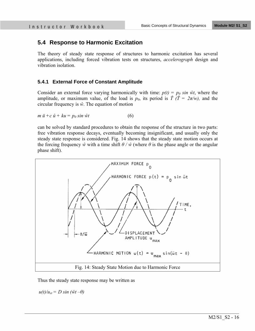
I n s t r u c t o r W o r k b o o k Basic Concepts of Structural Dynamics Module M2/ S1_S2
M2/S1_S2 - 16
5.4 Response to Harmonic Excitation
The theory of steady state response of structures to harmonic excitation has several applications, including forced vibration tests on structures, accelerograph design and vibration isolation.
5.4.1 External Force of Constant Amplitude
Consider an external force varying harmonically with time: p(t) = p0 sin ŵt, where the amplitude, or maximum value, of the load is p0, its period is Ť (Ť = 2π/w), and the circular frequency is ŵ. The equation of motion m ü +c ů + ku = p0 sin ŵt (6) can be solved by standard procedures to obtain the response of the structure in two parts: free vibration response decays, eventually becoming insignificant, and usually only the steady state response is considered. Fig. 14 shows that the steady state motion occurs at the forcing frequency ŵ with a time shift θ / ŵ (where θ is the phase angle or the angular phase shift).
Fig. 14: Steady State Motion due to Harmonic Force
Thus the steady state response may be written as u(t)/ust = D sin (ŵt –θ)
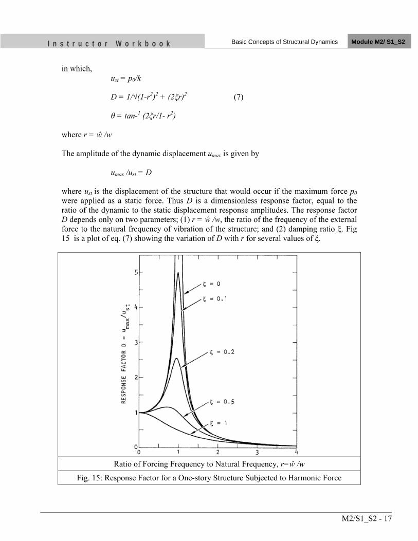
I n s t r u c t o r W o r k b o o k Basic Concepts of Structural Dynamics Module M2/ S1_S2
M2/S1_S2 - 17
in which, ust = p0/k D = 1/√(1-r2)2 + (2ξr)2 (7) θ = tan-1 (2ξr/1- r2) where r = ŵ /w The amplitude of the dynamic displacement umax is given by umax /ust = D where ust is the displacement of the structure that would occur if the maximum force p0 were applied as a static force. Thus D is a dimensionless response factor, equal to the ratio of the dynamic to the static displacement response amplitudes. The response factor D depends only on two parameters; (1) r = ŵ /w, the ratio of the frequency of the external force to the natural frequency of vibration of the structure; and (2) damping ratio ξ. Fig 15 is a plot of eq. (7) showing the variation of D with r for several values of ξ.
Ratio of Forcing Frequency to Natural Frequency, r=ŵ /w
Fig. 15: Response Factor for a One-story Structure Subjected to Harmonic Force
I n s t r u c t o r W o r k b o o k Basic Concepts of Structural Dynamics Module M2/ S1_S2
M2/S1_S2 - 18
For r close to zero, umax is about the same as ust; that is, the dynamic effects are negligible if the forcing frequency is much smaller than the natural frequency of the structure. For small values of r, the maximum displacement is controlled by the stiffness of the system with little effect of mass or damping. When r = 1, D =1/2ξ; that is, the response factor is inversely proportional to the damping ratio if the forcing frequency is the same as the natural frequency of the structure. For r close to 1, the response factor is controlled by the damping ratio ξ with negligible influence of mass or stiffness. The response factor is essentially independent of damping and approaches zero as the forcing frequency ŵ becomes much higher than the natural frequency w of the structure. It can be shown that at high forcing frequencies, the maximum displacement depends primarily on the mass. A resonant frequency is defined as the frequency for which the response is maximum. At very low values of ŵ (r close to zero) the response factor D is approximately equal to 1; it rises to a peak near ŵ = w (r = 1) and approaches zero as ŵ (or r) becomes large. It can be shown that the peak value of D occurs at r = √1-2ξ2 and the corresponding frequency is the displacement resonant frequency. Thus, the relations among the displacement resonant frequency, the damped natural frequency wD, and the undamped natural frequency w are Displacement resonant frequency = w√1-2ξ2
Damped natural frequency wD = w√1-ξ2
Although the displacement resonant frequency is different from the damped or undamped natural frequencies, the difference is negligible for the degree of damping typical of structures- less than 4% if the damping ratio does not exceed 20%.
5.5 Response to Earthquake Ground Motion
5.5.1 Response History
The motion of the one-storey structure subjected to earthquake ground motion (Fig 7a) can be written as ü +2 ξ w ů + w2u = - üg(t) (8) The solution to this equation leads to the deformation response u(t), which depends on (1) the characteristics of the ground acceleration üg(t), (2) w = √k/m, the natural circular frequency of vibration (or equivalently the natural period of vibration (T) of the structure without damping, and (3) the damping ratio ξ of the structure. The solution to this equation can be written as
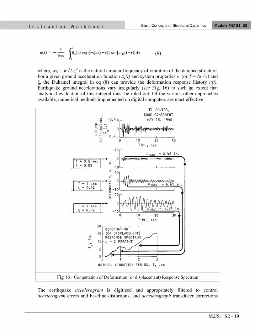
I n s t r u c t o r W o r k b o o k Basic Concepts of Structural Dynamics Module M2/ S1_S2
M2/S1_S2 - 19
(9)
where, wD = w√1-ξ2 is the natural circular frequency of vibration of the damped structure. For a given ground acceleration function üg(t) and system properties w (or T =2π /w) and ξ, the Duhamel integral in eq (8) can provide the deformation response history u(t). Earthquake ground accelerations vary irregularly (see Fig. 16) to such an extent that analytical evaluation of this integral must be ruled out. Of the various other approaches available, numerical methods implemented on digital computers are most effective.
Fig 16 : Computation of Deformation (or displacement) Response Spectrum The earthquake accelerogram is digitized and appropriately filtered to control accelerogram errors and baseline distortions, and accelerograph transducer corrections
I n s t r u c t o r W o r k b o o k Basic Concepts of Structural Dynamics Module M2/ S1_S2
M2/S1_S2 - 20
are introduced to obtain the corrected ground accelerogram (Hudson 1979). The function üg(t) in equations (8) and (9) is then defined by the numerical coordinates of the corrected accelerogram at time intervals spaced closely enough to accurately define the accelerogram. With the ground acceleration üg(t) defined in this manner and substituting numerical values for w and ξ of the structure in equation (9) , the response history could be determined by numerical evaluation of the Duhamel integral. The more common approach, however, is to directly solve the equation of motion (8) by numerical procedures for which various procedures have been developed. When properly implemented, both approaches - the numerical evaluation of the Duhamel integral and the numerical solution of the equation of motion-provide equivalent results. Fig. 16 shows the results of such computations for three structures subjected to the same ground motion. The damping ratio ξ = 2% is the same for the three structures, so that the differences in their deformation responses are associated with their natural period of vibration. The time required for the structure to complete a cycle of vibration in response to typical earthquake ground motion is very close to the natural period of vibration of the structure. Mathematical expressions can also be obtained for other response quantities such as relative velocity ů(t) and total acceleration üt(t). Once the deformation response history u(t) has been evaluated, the shear and moment at the base of the building can be conveniently determined by introducing the concept of equivalent lateral force. This is an external force fs that, if applied as a static force, would cause deformation u (Fig 17). Thus, at any given time the equivalent lateral force is fs(t) = ku(t) which can be expressed in terms of the mass as fs(t) = mw2u(t)
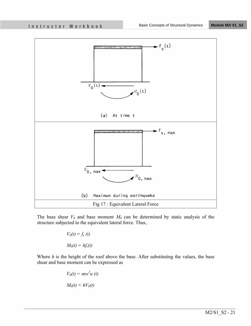
I n s t r u c t o r W o r k b o o k Basic Concepts of Structural Dynamics Module M2/ S1_S2
M2/S1_S2 - 21
Fig 17 : Equivalent Lateral Force
The base shear V0 and base moment M0 can be determined by static analysis of the structure subjected to the equivalent lateral force. Thus, V0(t) = fs (t) M0(t) = hfs(t) Where h is the height of the roof above the base. After substituting the values, the base shear and base moment can be expressed as V0(t) = mw2u (t) M0(t) = hV0(t)
I n s t r u c t o r W o r k b o o k Basic Concepts of Structural Dynamics Module M2/ S1_S2
M2/S1_S2 - 22
5.6 Response Spectrum
The complete history of any response quantity, namely deformation, velocity, acceleration, base shear, or base moment, can be determined by the numerical procedures. However, for design purposes, it is generally sufficient to know only the maximum value of the response due to the earthquake. The subscript max will generally be used to designate the maximum value of the response, without regard to algebraic sign. Thus, for any response quantity r, rmax = max | r(t) | A plot of the maximum value of a response quantity as a function of the natural vibration frequency of the structure, or as a function of a quantity which is related to the frequency such as natural period, constitutes the response spectrum for that quantity. The deformation (or displacement) response spectrum is a plot of the quantity Sd defined as Sd = u max Fig 16 shows the basic concept underlying computation of the deformation response spectrum. The time variations of deformation responses of three structures to a selected ground motion are presented. For each structure the maximum value of the deformation, without regard to algebraic sign, during the earthquake is determined from its response history. The umax so determined for each structure provides one point on the deformation response spectrum. Repeating such computation for a range of values of T, while keeping the damping ratio ξ constant, provides the deformation response spectrum for the ground motion. The complete response spectrum includes such spectrum curves for several values of damping. Alternatively the maximum deformation may be expressed in terms of the quantity Sv defined as Sv = w Sd (10) Or equivalently as Sv = 2π/T Sd Where w is the natural circular frequency of vibration of the structure and T is the natural vibration period of the structure. The quantity Sv has units of velocity and is related to maximum strain energy Emax stored in the structure during the earthquake by the equation Emax = ½ m Sv
2
which can be derived as follows:
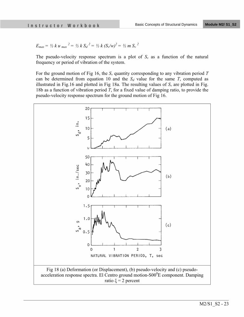
I n s t r u c t o r W o r k b o o k Basic Concepts of Structural Dynamics Module M2/ S1_S2
M2/S1_S2 - 23
Emax = ½ k u max 2 = ½ k Sd 2 = ½ k (Sv/w)2 = ½ m Sv 2 The pseudo-velocity response spectrum is a plot of Sv as a function of the natural frequency or period of vibration of the system. For the ground motion of Fig 16, the Sv quantity corresponding to any vibration period T can be determined from equation 10 and the Sd value for the same T, computed as illustrated in Fig.16 and plotted in Fig 18a. The resulting values of Sv are plotted in Fig. 18b as a function of vibration period T, for a fixed value of damping ratio, to provide the pseudo-velocity response spectrum for the ground motion of Fig 16.
Fig 18 (a) Deformation (or Displacement), (b) pseudo-velocity and (c) pseudo-acceleration response spectra. El Centro ground motion-S000E component. Damping
ratio ξ = 2 percent
I n s t r u c t o r W o r k b o o k Basic Concepts of Structural Dynamics Module M2/ S1_S2
M2/S1_S2 - 24
Another convenient measure of the maximum deformation is the quantity Sa, defined as Sa = w Sv = w2 Sd (11) Or equivalently as Sa = 2π/T Sv = (2π/T)2 Sd (12) The quantity Sa has units of acceleration an is related to the maximum value of the base shear as follows: V0, max = kSd = mw2Sd = mSa The maximum base shear may be written in the form V0, max = Sa/g*w Where w is the weight of the system and g is the acceleration due to gravity. Sa/g may be interpreted as the so-called base shear coefficient in building codes. The pseudo-acceleration response spectrum is a plot of Sa as a function of the natural frequency or the period of vibration of the system. For the ground motion of Fig 16, the Sa value corresponding to any value of T can be determined using equation (12) and the Sd value for the same T, computed as illustrated in Fig 16 and plotted in 19a. The resulting values of Sa are plotted in Fig 19c as a function of vibration period T, for a fixed value of damping ratio, to provide the pseudo-acceleration response spectrum for the ground motion of Fig 16. The deformation, pseudo-velocity, and pseudo-acceleration response spectra for an earthquake ground motion are interrelated through equation 11. Any one of these spectra can be obtained from one of the two, and each of the three spectra contains the same information. The three spectra are simply different ways of presenting the same information on structural response. 6. DYNAMICS OF MULTISTOREY BULDINGS It is desirable to begin the study of dynamics of multistory buildings with their simplest possible idealization, as shown in Fig. 19. The masses concentrated at the floor levels are denoted by m1, m2, . . . mn where mj, = mass at the jth floor. The stiffness properties of the linear structure are characterized by the lateral stiffness k1, k2, . . . kN of individual stories, where k = lateral stiffness of the jth story, i.e. the storey shear force required to cause unit deformation in the storey (Fig. 19). It will be convenient to first develop the
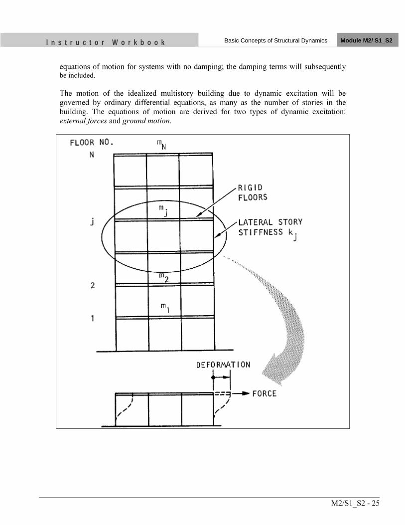
I n s t r u c t o r W o r k b o o k Basic Concepts of Structural Dynamics Module M2/ S1_S2
M2/S1_S2 - 25
equations of motion for systems with no damping; the damping terms will subsequently be included. The motion of the idealized multistory building due to dynamic excitation will be governed by ordinary differential equations, as many as the number of stories in the building. The equations of motion are derived for two types of dynamic excitation: external forces and ground motion.
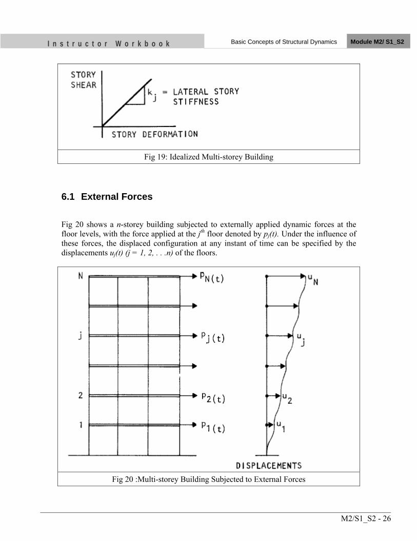
I n s t r u c t o r W o r k b o o k Basic Concepts of Structural Dynamics Module M2/ S1_S2
M2/S1_S2 - 26
Fig 19: Idealized Multi-storey Building
6.1 External Forces
Fig 20 shows a n-storey building subjected to externally applied dynamic forces at the floor levels, with the force applied at the jth floor denoted by pj(t). Under the influence of these forces, the displaced configuration at any instant of time can be specified by the displacements uj(t) (j = 1, 2, . . .n) of the floors.
Fig 20 :Multi-storey Building Subjected to External Forces
I n s t r u c t o r W o r k b o o k Basic Concepts of Structural Dynamics Module M2/ S1_S2
M2/S1_S2 - 27
The n equations of motion for this structure can also be expressed in the form
mü +ců +ku = p(t) (13)
where, m is the mass matrix
c is the damping matrix and k is the stiffness matrix
The displacement and external force vectors are
6.2 Earthquake Ground Motion
No external dynamic forces are applied to the idealized n-storey structure shown in Fig. 21. The excitation in this case is the earthquake induced motion at the base of the structure, presumed to be only a horizontal component of ground motion with displacement ug(t), velocity ůg(t) and acceleration üg(t). Under the influence of such an
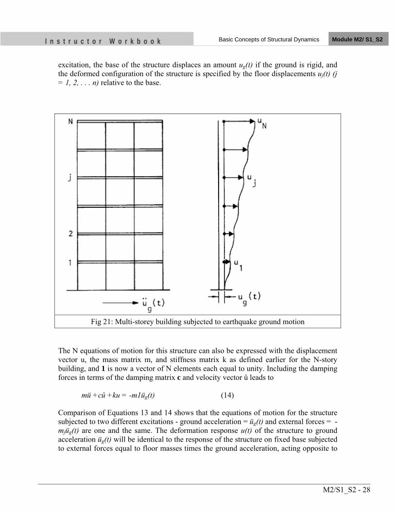
I n s t r u c t o r W o r k b o o k Basic Concepts of Structural Dynamics Module M2/ S1_S2
M2/S1_S2 - 28
excitation, the base of the structure displaces an amount ug(t) if the ground is rigid, and the deformed configuration of the structure is specified by the floor displacements uj(t) (j = 1, 2, . . . n) relative to the base.
Fig 21: Multi-storey building subjected to earthquake ground motion
The N equations of motion for this structure can also be expressed with the displacement vector u, the mass matrix m, and stiffness matrix k as defined earlier for the N-story building, and 1 is now a vector of N elements each equal to unity. Including the damping forces in terms of the damping matrix c and velocity vector ů leads to
mü +ců +ku = -m1üg(t) (14)
Comparison of Equations 13 and 14 shows that the equations of motion for the structure subjected to two different excitations - ground acceleration = üg(t) and external forces = -mjüg(t) are one and the same. The deformation response u(t) of the structure to ground acceleration üg(t) will be identical to the response of the structure on fixed base subjected to external forces equal to floor masses times the ground acceleration, acting opposite to
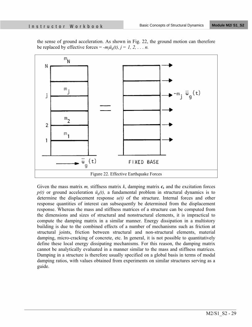
I n s t r u c t o r W o r k b o o k Basic Concepts of Structural Dynamics Module M2/ S1_S2
M2/S1_S2 - 29
the sense of ground acceleration. As shown in Fig. 22, the ground motion can therefore be replaced by effective forces = -mjüg(t), j = 1, 2, . . . n.
Figure 22. Effective Earthquake Forces Given the mass matrix m, stiffness matrix k, damping matrix c, and the excitation forces p(t) or ground acceleration üg(t), a fundamental problem in structural dynamics is to determine the displacement response u(t) of the structure. Internal forces and other response quantities of interest can subsequently be determined from the displacement response. Whereas the mass and stiffness matrices of a structure can be computed from the dimensions and sizes of structural and nonstructural elements, it is impractical to compute the damping matrix in a similar manner. Energy dissipation in a multistory building is due to the combined effects of a number of mechanisms such as friction at structural joints, friction between structural and non-structural elements, material damping, micro-cracking of concrete, etc. In general, it is not possible to quantitatively define these local energy dissipating mechanisms. For this reason, the damping matrix cannot be analytically evaluated in a manner similar to the mass and stiffness matrices. Damping in a structure is therefore usually specified on a global basis in terms of modal damping ratios, with values obtained from experiments on similar structures serving as a guide.
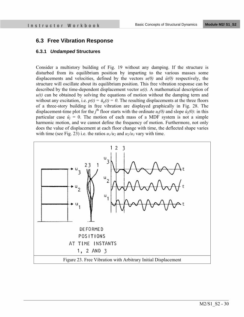
I n s t r u c t o r W o r k b o o k Basic Concepts of Structural Dynamics Module M2/ S1_S2
M2/S1_S2 - 30
6.3 Free Vibration Response
6.3.1 Undamped Structures
Consider a multistory building of Fig. 19 without any damping. If the structure is disturbed from its equilibrium position by imparting to the various masses some displacements and velocities, defined by the vectors u(0) and ů(0) respectively, the structure will oscillate about its equilibrium position. This free vibration response can be described by the time-dependent displacement vector u(t). A mathematical description of u(t) can be obtained by solving the equations of motion without the damping term and without any excitation, i.e. p(t) = üg(t) = 0. The resulting displacements at the three floors of a three-story building in free vibration are displayed graphically in Fig. 28. The displacement-time plot for the jth floor starts with the ordinate uj(0) and slope ůj(0): in this particular case ůj = 0. The motion of each mass of a MDF system is not a simple harmonic motion, and we cannot define the frequency of motion. Furthermore, not only does the value of displacement at each floor change with time, the deflected shape varies with time (see Fig. 23) i.e. the ratios u1/u2 and u2/u3 vary with time.
Figure 23. Free Vibration with Arbitrary Initial Displacement
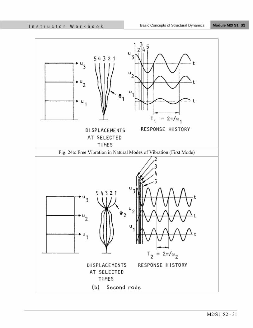
I n s t r u c t o r W o r k b o o k Basic Concepts of Structural Dynamics Module M2/ S1_S2
M2/S1_S2 - 31
Fig. 24a: Free Vibration in Natural Modes of Vibration (First Mode)
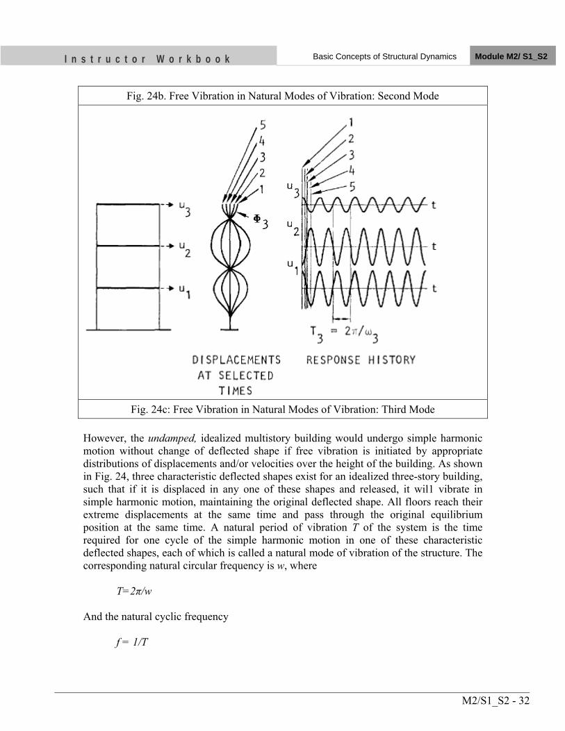
I n s t r u c t o r W o r k b o o k Basic Concepts of Structural Dynamics Module M2/ S1_S2
M2/S1_S2 - 32
Fig. 24b. Free Vibration in Natural Modes of Vibration: Second Mode
Fig. 24c: Free Vibration in Natural Modes of Vibration: Third Mode
However, the undamped, idealized multistory building would undergo simple harmonic motion without change of deflected shape if free vibration is initiated by appropriate distributions of displacements and/or velocities over the height of the building. As shown in Fig. 24, three characteristic deflected shapes exist for an idealized three-story building, such that if it is displaced in any one of these shapes and released, it wil1 vibrate in simple harmonic motion, maintaining the original deflected shape. All floors reach their extreme displacements at the same time and pass through the original equilibrium position at the same time. A natural period of vibration T of the system is the time required for one cycle of the simple harmonic motion in one of these characteristic deflected shapes, each of which is called a natural mode of vibration of the structure. The corresponding natural circular frequency is w, where T=2π/w And the natural cyclic frequency f = 1/T
I n s t r u c t o r W o r k b o o k Basic Concepts of Structural Dynamics Module M2/ S1_S2
M2/S1_S2 - 33
Fig. 24 shows the three natural periods Tn (n = 1, 2, 3) of the three-story building vibrating in its natural modes of vibration defined by vectors φn. The smallest of the three circular frequencies is denoted as w1 the largest as w3, and the intermediate frequency as w2. Correspondingly the longest of three vibration periods is denoted as T1 the shortest as T3 and the intermediate period as T2. The vector φn, defines only the deflected shape of the structure vibrating in its nth natural mode of vibration, i.e. it does not define the floor displacements v1, v2 and v3 but only their ratios, say v1/v3 and v2/v3. The vibration mode can be normalized by multiplying the vector φn by any quantity. For example, the multiplier may be chosen so that the normalized vector φn contains a unit value for the top floor. Modes may be normalized simply for convenience. How they are normalized does not affect the final results of dynamic response analysis. An idealized n-story building possesses n natural circular frequencies of vibration wn (n = 1, 2, . . . N) arranged in sequence from smallest to largest, corresponding natural periods Tn and natural modes of vibration φn. The term natural is used to qualify each of the above vibration quantities to emphasize the fact that these are natural properties of the structure, depending on its stiffness and mass, when it is allowed to vibrate freely without any external excitation. We refer to wn as the nth natural circular frequency of vibration, Tn as the nth natural period of vibration and φn as the nth natural mode of vibration. The quantities w1, T1 and φ1 are also referred to as the fundamental frequency, period, and mode of vibration of the structure.
6.3.2 Damped Structures
Consider an idealized multistory building with damping, disturbed from its equilibrium position by displacing it in a natural mode of vibration of the corresponding undamped structure, a system with stiffness and mass properties identical to the building but with no damping. For certain forms of damping that are reasonable models for many buildings, the initial deflected shape will be maintained during the free vibration and the motion of any floor will be similar to that of the undamped structure shown in Fig. 24; except that, because of damping. The amplitude of motion at each floor would decrease with every cycle of vibration. The period TnD, circular frequency wnD, cyclic frequency fnD, of the nth mode of vibration of the damped structure are interrelated in the same manner as for the undamped structure. Damping influences the natural frequencies and periods of vibration of the multistory structure in the same manner as for the SDF system. Thus, wnD = wn √1-ξn
2 TnD = Tn √1-ξn
2 where ξn is the damping ratio for the multistory building in its nth natural mode of vibration. However, for damping ratios less than 0.2, a range which includes most structures, the effects of damping on vibration frequencies are negligible. The natural
I n s t r u c t o r W o r k b o o k Basic Concepts of Structural Dynamics Module M2/ S1_S2
M2/S1_S2 - 34
frequencies and modes of vibration of a structure can therefore be computed under the assumption that the structure is undamped. In a multistory structure undergoing free vibration in its nth natural mode of vibration, the displacement amplitude at any floor decreases with each vibration cycle. The rate of decay depends on the damping ratio ξn, in that mode, in a manner similar to one-story structures. Thus the ratio of two response peaks separated by j cycles of vibration is related to the damping ratio with appropriate change in notation. Consequently, the damping ratio in a natural mode of vibration of a multistory building can be determined from a free vibration test following the procedure for one storey structures. In such a test, the structure would be deformed by pulling on it with a cable that is then suddenly released, thus causing the structure to perform free vibrations about its static equilibrium position. A difficulty in such tests is to apply the pull and release in such a way that the structure will vibrate in one of its natural modes of vibration. But if this difficulty can be overcome, the damping ratio can be computed from the decay rate of vibration amplitudes.
6.4 Response to Harmonic Excitation
Consider external forces varying harmonically with time applied at the various floors of the idealized multistory building. The external force at the jth floor pj(t) = p0j sin ŵ t , where the amplitude or maximum value of the force is p0j, its period Ť = 2π /ŵ, and circular frequency is ŵ. Starting with the floor masses and story stiffness, the mass and stiffness matrices of the system can be formed as described earlier, and then the natural frequencies and modes of vibration can be computed. For specific values of damping ratios ξn in the natural modes of vibration, the dynamic response of the structure to the harmonic forces can be determined by the mode superposition method (Newmark and Rosenblueth, 1971-Chapter 2; Clough and Penzien, 1975-Chapter 13). The response of the structure consists of two parts: free vibration response plus steady state response. In a damped structure, the free vibration response decays, eventually becoming insignificant, and usually only the steady state response is considered. The frequency of the steady state response is the same as the forcing frequency ŵ, and the phase between the force and the response is different from zero. The steady state displacement at the jth floor can be expressed as uj(t)/uj,st = Dj sin (ŵt-θj) where uj,st = displacement at the jth floor of the structure if the maximum forces p0j, are applied as static forces; and θj is the phase angle, or the angular phase shift. The amplitude of the dynamic displacement at the jth floor uj,max is given by uj,max/uj,st = Dj
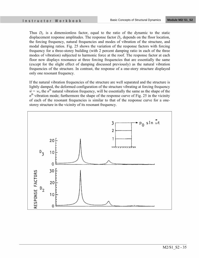
I n s t r u c t o r W o r k b o o k Basic Concepts of Structural Dynamics Module M2/ S1_S2
M2/S1_S2 - 35
Thus Dj, is a dimensionless factor, equal to the ratio of the dynamic to the static displacement response amplitudes. The response factor Dj, depends on the floor location, the forcing frequency, natural frequencies and modes of vibration of the structure, and modal damping ratios. Fig. 25 shows the variation of the response factors with forcing frequency for a three-storey building (with 2 percent damping ratio in each of the three modes of vibration) subjected to harmonic force at the roof. The response factor at each floor now displays resonance at three forcing frequencies that are essentially the same (except for the slight effect of damping discussed previously) as the natural vibration frequencies of the structure. In contrast, the response of a one-story structure displayed only one resonant frequency. If the natural vibration frequencies of the structure are well separated and the structure is lightly damped, the deformed configuration of the structure vibrating at forcing frequency ŵ = wn the nth natural vibration frequency, will be essentially the same as the shape of the nth vibration mode; furthermore the shape of the response curve of Fig. 25 in the vicinity of each of the resonant frequencies is similar to that of the response curve for a one-storey structure in the vicinity of its resonant frequency.
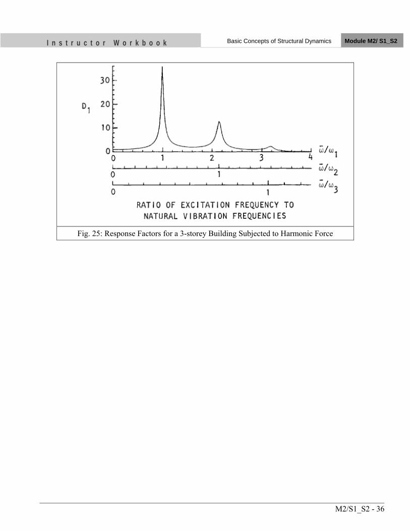
I n s t r u c t o r W o r k b o o k Basic Concepts of Structural Dynamics Module M2/ S1_S2
M2/S1_S2 - 36
Fig. 25: Response Factors for a 3-storey Building Subjected to Harmonic Force
I n s t r u c t o r W o r k b o o k Basic Concepts of Structural Dynamics Module M2/ S1_S2
M2/S1_S2 - 37
UNIT TEST 1) Define the following terms
• Free vibration motion ..... • Structural Damping ......
• Time Period T of oscillation .......
2) Discuss Dynamic VS Static Problem
• Static problem is …….. • ……
3) Write the equation of motion for one storey building subjected to external
force • ……
4) Write the formula of damping ratio ξ for j cycles apart of a damped free vibration of a structure
• ……
5) What are the sources of energy dissipation or structural damping in a building structure?
• ….. • ….. • …… • ……
OBJECTIVES
As a result of this session, you should be able to:
• Identify the difference between earthquake resistant and earthquake proof building.
• Indentify the philosophy of earthquake resistant building design.
• Identify the analysis methods of seismic design.
Instructor Workbook Module M2/ S3
Philosophy of Earthquake Resistant Design
M2/S3-1
CONTENTS
1 Introduction ................................................................................................................................. 2
2 DESIGN PHILOSOPHY ............................................................................................................ 2
2.1 Difference between Normal Load and Lateral Load Design ............................................ 3
2.2 Actual Design Earthquake Force Level ............................................................................ 5
2.3 Historical Development ..................................................................................................... 6
2.4 Design Process ................................................................................................................... 6
2.5 Preliminary design ............................................................................................................. 6
3 Analysis Methods ......................................................................................................................... 7
3.1 Design Earthquake Load ................................................................................................... 8
3.2 Seismic Zoning Factor ....................................................................................................... 9
3.3 Importance Factor ............................................................................................................ 10
Governing Factors For I................................................................................................... 10
3.4 Structural Performance Factor, K .................................................................................... 11
Governing Factors For K ................................................................................................. 11
3.5 Basic Seismic Coefficient , C .......................................................................................... 11
3.6 Response Spectra, C-value .............................................................................................. 12
3.7 Fundamental Time Period, T ........................................................................................... 12
3.8 Site Subsoil Category ...................................................................................................... 13
3.9 Soil-Structure Effect ........................................................................................................ 14
3.10 Vertical Distribution of Base Shear ................................................................................. 14
3.11 Preliminary design ........................................................................................................... 15
3.12 Final design ...................................................................................................................... 16
3.13 Earthquake Resistant Elements in Masonry Building .................................................... 16
M2/S3-2
I n s t r u c t o r W o r k b o o k Philosophy of Earthquake Resistant Design Module M2/S3
1 INTRODUCTION
Severity of ground shaking at a given location during an earthquake can be minor, moderate
and strong. Thus relatively speaking, minor shaking occurs frequently; moderate shaking
occasionally and strong shaking rarely. For instance, on average annually about 800
earthquakes of magnitude 5.0 - 5.9 occur in the world while about 18 for magnitude range 7.0
- 7.9. So should we design and construct a building to resist that rare earthquake shaking that
may come only once in 500 years or even once in 2000 years, even though the life of the
building may be 50 or 100 years?
Engineers do not attempt to make earthquake proof buildings that will not get damaged even
during the rare but strong earthquake; such buildings will be too robust and also too
expensive. Instead the engineering intention is to make buildings earthquake-resistant; such
buildings resist the effects of ground shaking, although they may get damaged severely but
would not collapse during the strong earthquake. Thus, safety of people and contents is
assured in earthquake-resistant buildings, and thereby a disaster is avoided. This is a major
objective of seismic design codes throughout the world.
2 DESIGN PHILOSOPHY
a) Under minor but frequent shaking, the main members of the buildings that carry
vertical and horizontal forces should not be damaged; however buildings parts that do
not carry load may sustain repairable damage.
b) Under moderate but occasional shaking, the main members may sustain
repairable damage, while the other parts that do not carry load may sustain repairable
damage.
c) Under strong but rare shaking, the main members may sustain severe damage,
but the building should not collapse.
Earthquake resistant design is therefore concerned about ensuring that the damages in
buildings during earthquakes are of acceptable variety, and also that they occur at the
M2/S3-3
I n s t r u c t o r W o r k b o o k Philosophy of Earthquake Resistant Design Module M2/S3
right places and in right amounts. This approach of earthquake resistant design is
much like the use of electrical fuses in houses: to protect the entire electrical wiring
and appliances in the house, you sacrifice some small parts of electrical circuit, called
fuses; these fuses are easily replaced after the electrical over-current. Likewise to save
the building from collapsing you need to allow some pre-determined parts to undergo
the acceptable type and level of damage.
Earthquake resistant buildings, particularly their main elements, need to be built with
ductility in them. Such buildings have the ability to sway back-and-forth during an
earthquake, and to withstand the earthquake effects with some damage, but without
collapse.
1. Structure should remain essentially elastic in frequent minor ground shaking
2. Structure should be able to resist occasional moderate ground shaking without
significant damage
3. Structure should be able to resist major earthquakes without collapse
2.1 Difference between Normal Load and Lateral Load Design
1. In Ordinary Load (dead/ Imposed, wind etc), it is expected that structure will
essentially remain elastic even during severe most design loading
2. Where as in earthquake resistant design, it is expected that structure could go in
inelastic regime and suffer severe damage during a major earthquake
We thrive for Earthquake resistant design & construction not Earthquake proof
1. Buildings and other structures are designed for much lesser load than imparted by
large earthquakes for affordability because large earthquakes are rare.
2. Properly designed Buildings have Ductility, Redundancy.
3. Building has over strength due to considered safety factors in loads and materials.
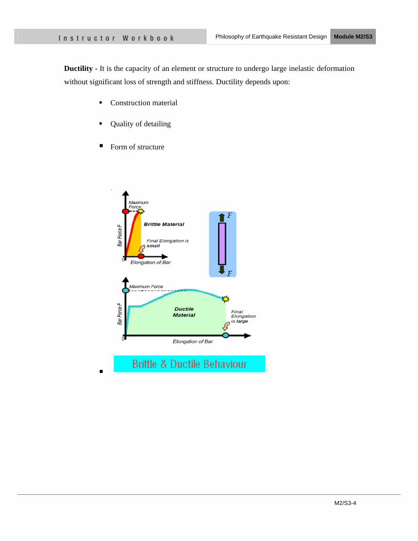
M2/S3-4
I n s t r u c t o r W o r k b o o k Philosophy of Earthquake Resistant Design Module M2/S3
Ductility - It is the capacity of an element or structure to undergo large inelastic deformation
without significant loss of strength and stiffness. Ductility depends upon:
Construction material
Quality of detailing
Form of structure
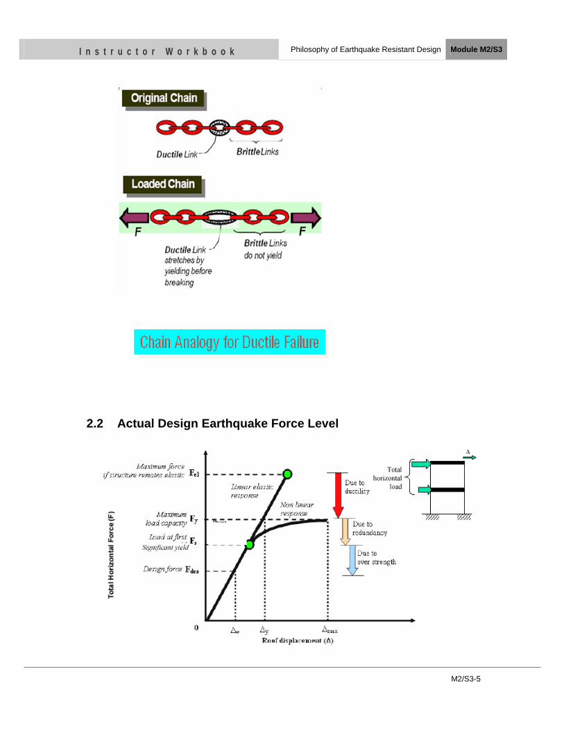
M2/S3-5
I n s t r u c t o r W o r k b o o k Philosophy of Earthquake Resistant Design Module M2/S3
2.2 Actual Design Earthquake Force Level
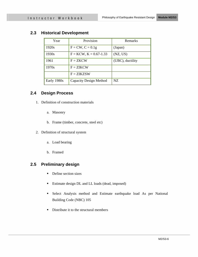
M2/S3-6
I n s t r u c t o r W o r k b o o k Philosophy of Earthquake Resistant Design Module M2/S3
2.3 Historical Development
Year Provision Remarks
1920s F = CW, C = 0.1g (Japan)
1930s F = KCW, K = 0.67-1.33 (NZ, US)
1961 F = ZKCW (UBC), ductility
1970s F = ZIKCW
F = ZIKZSW
Early 1980s Capacity Design Method NZ
2.4 Design Process
1. Definition of construction materials
a. Masonry
b. Frame (timber, concrete, steel etc)
2. Definition of structural system
a. Load bearing
b. Framed
2.5 Preliminary design
Define section sizes
Estimate design DL and LL loads (dead, imposed)
Select Analysis method and Estimate earthquake load As per National
Building Code (NBC) 105
Distribute it to the structural members
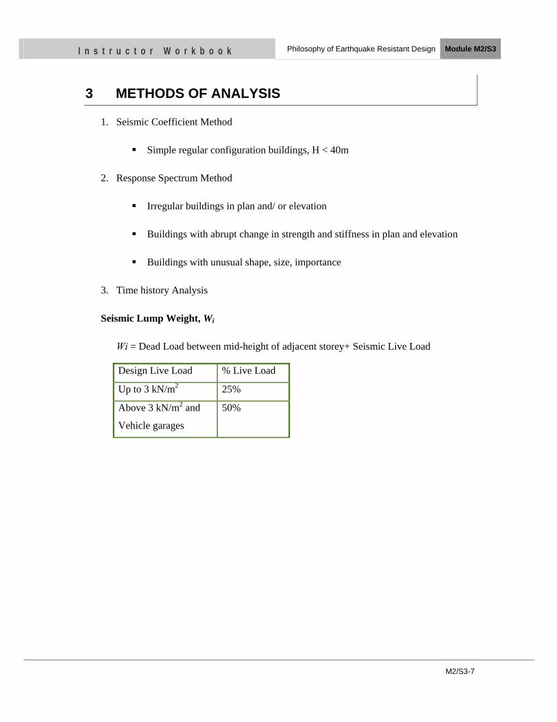
M2/S3-7
I n s t r u c t o r W o r k b o o k Philosophy of Earthquake Resistant Design Module M2/S3
3 METHODS OF ANALYSIS
1. Seismic Coefficient Method
Simple regular configuration buildings, H < 40m
2. Response Spectrum Method
Irregular buildings in plan and/ or elevation
Buildings with abrupt change in strength and stiffness in plan and elevation
Buildings with unusual shape, size, importance
3. Time history Analysis
Seismic Lump Weight, Wi
Wi = Dead Load between mid-height of adjacent storey+ Seismic Live Load
Design Live Load % Live Load
Up to 3 kN/m2 25%
Above 3 kN/m2 and
Vehicle garages
50%
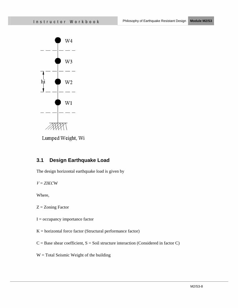
M2/S3-8
I n s t r u c t o r W o r k b o o k Philosophy of Earthquake Resistant Design Module M2/S3
3.1 Design Earthquake Load
The design horizontal earthquake load is given by
V = ZIKCW
Where,
Z = Zoning Factor
I = occupancy importance factor
K = horizontal force factor (Structural performance factor)
C = Base shear coefficient, S = Soil structure interaction (Considered in factor C)
W = Total Seismic Weight of the building
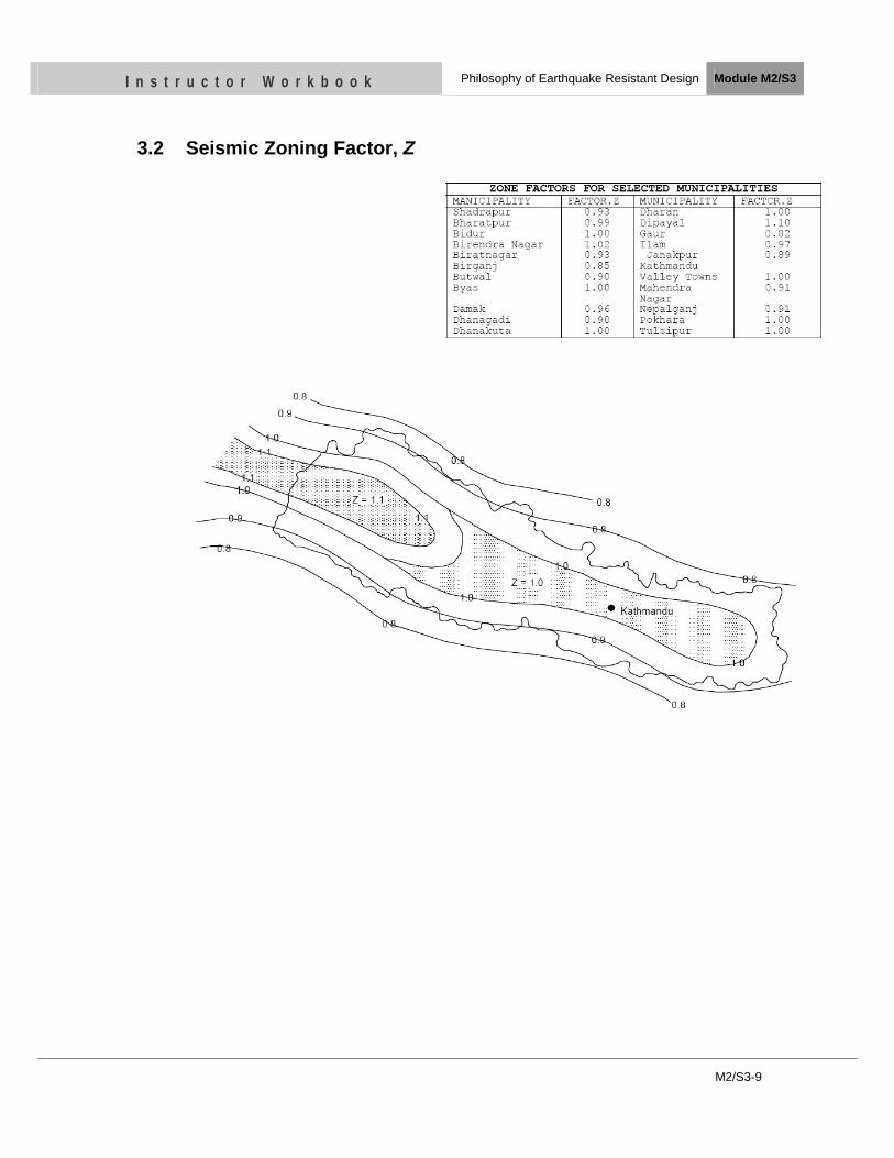
M2/S3-9
I n s t r u c t o r W o r k b o o k Philosophy of Earthquake Resistant Design Module M2/S3
3.2 Seismic Zoning Factor, Z
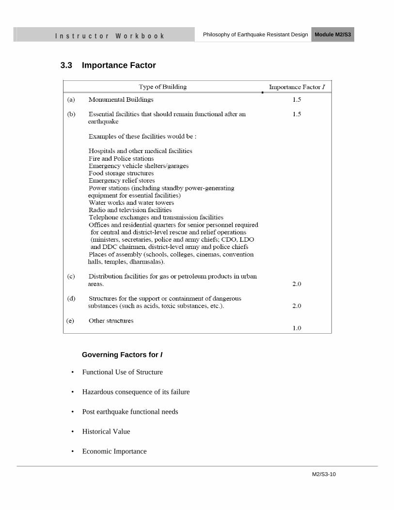
M2/S3-10
I n s t r u c t o r W o r k b o o k Philosophy of Earthquake Resistant Design Module M2/S3
3.3 Importance Factor
Governing Factors for I
• Functional Use of Structure
• Hazardous consequence of its failure
• Post earthquake functional needs
• Historical Value
• Economic Importance
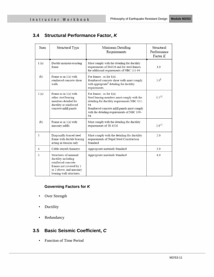
M2/S3-11
I n s t r u c t o r W o r k b o o k Philosophy of Earthquake Resistant Design Module M2/S3
3.4 Structural Performance Factor, K
Governing Factors for K
• Over Strength
• Ductility
• Redundancy
3.5 Basic Seismic Coefficient, C
• Function of Time Period
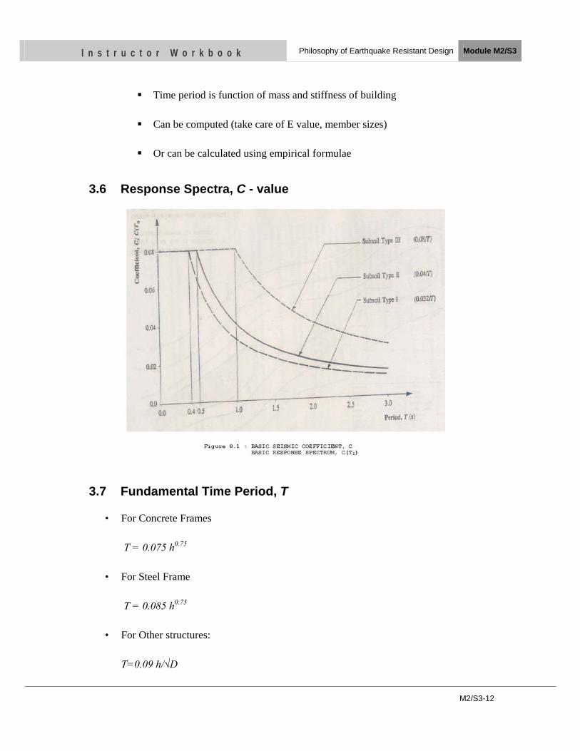
M2/S3-12
I n s t r u c t o r W o r k b o o k Philosophy of Earthquake Resistant Design Module M2/S3
Time period is function of mass and stiffness of building
Can be computed (take care of E value, member sizes)
Or can be calculated using empirical formulae
3.6 Response Spectra, C - value
3.7 Fundamental Time Period, T
• For Concrete Frames
T = 0.075 h0.75
• For Steel Frame
T = 0.085 h0.75
• For Other structures:
T=0.09 h/√D
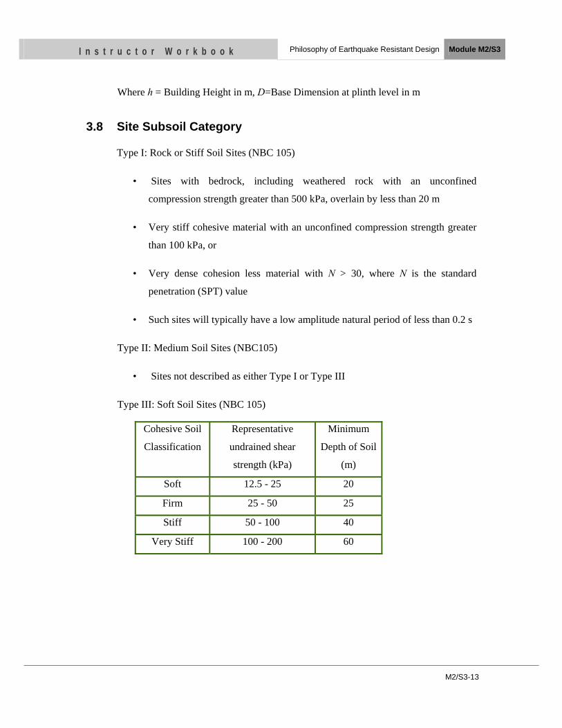
M2/S3-13
I n s t r u c t o r W o r k b o o k Philosophy of Earthquake Resistant Design Module M2/S3
Where h = Building Height in m, D=Base Dimension at plinth level in m
3.8 Site Subsoil Category
Type I: Rock or Stiff Soil Sites (NBC 105)
• Sites with bedrock, including weathered rock with an unconfined
compression strength greater than 500 kPa, overlain by less than 20 m
• Very stiff cohesive material with an unconfined compression strength greater
than 100 kPa, or
• Very dense cohesion less material with N > 30, where N is the standard
penetration (SPT) value
• Such sites will typically have a low amplitude natural period of less than 0.2 s
Type II: Medium Soil Sites (NBC105)
• Sites not described as either Type I or Type III
Type III: Soft Soil Sites (NBC 105)
Cohesive Soil
Classification
Representative
undrained shear
strength (kPa)
Minimum
Depth of Soil
(m)
Soft 12.5 - 25 20
Firm 25 - 50 25
Stiff 50 - 100 40
Very Stiff 100 - 200 60
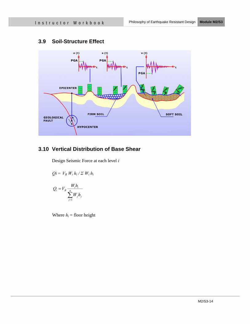
M2/S3-14
I n s t r u c t o r W o r k b o o k Philosophy of Earthquake Resistant Design Module M2/S3
3.9 Soil-Structure Effect
3.10 Vertical Distribution of Base Shear
Design Seismic Force at each level i
Qi = VB Wi hi / Σ Wi hi
Where hi = floor height
∑=
= n
jjj
iiBi
hW
hWVQ
1

M2/S3-15
I n s t r u c t o r W o r k b o o k Philosophy of Earthquake Resistant Design Module M2/S3
Load Combinations (NBC105)
Design Method Analysis Method
Working Stress Method DL + LL + E
0.7 DL + E
DL +SL + E
Limit State Method DL + 1.3 LL + 1.25 E
0.9 DL + 1.25 E
DL + 1.3 SL + 1.25 E
3.11 Preliminary design
Analyze building for defined material, structural system, loading etc. (assess
bending moment, shear force, axial load)
Design the section
Check the requirements of Code
Check if the design meets the requirements of Code
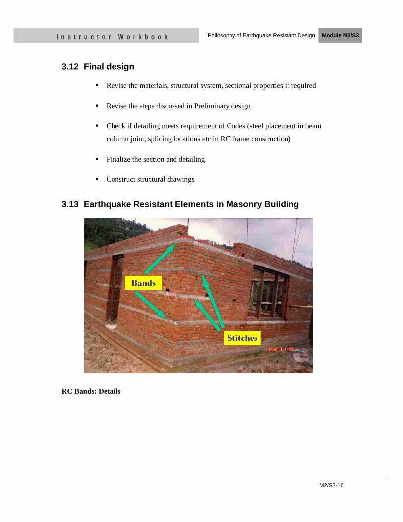
M2/S3-16
I n s t r u c t o r W o r k b o o k Philosophy of Earthquake Resistant Design Module M2/S3
3.12 Final design
Revise the materials, structural system, sectional properties if required
Revise the steps discussed in Preliminary design
Check if detailing meets requirement of Codes (steel placement in beam
column joint, splicing locations etc in RC frame construction)
Finalize the section and detailing
Construct structural drawings
3.13 Earthquake Resistant Elements in Masonry Building
RC Bands: Details
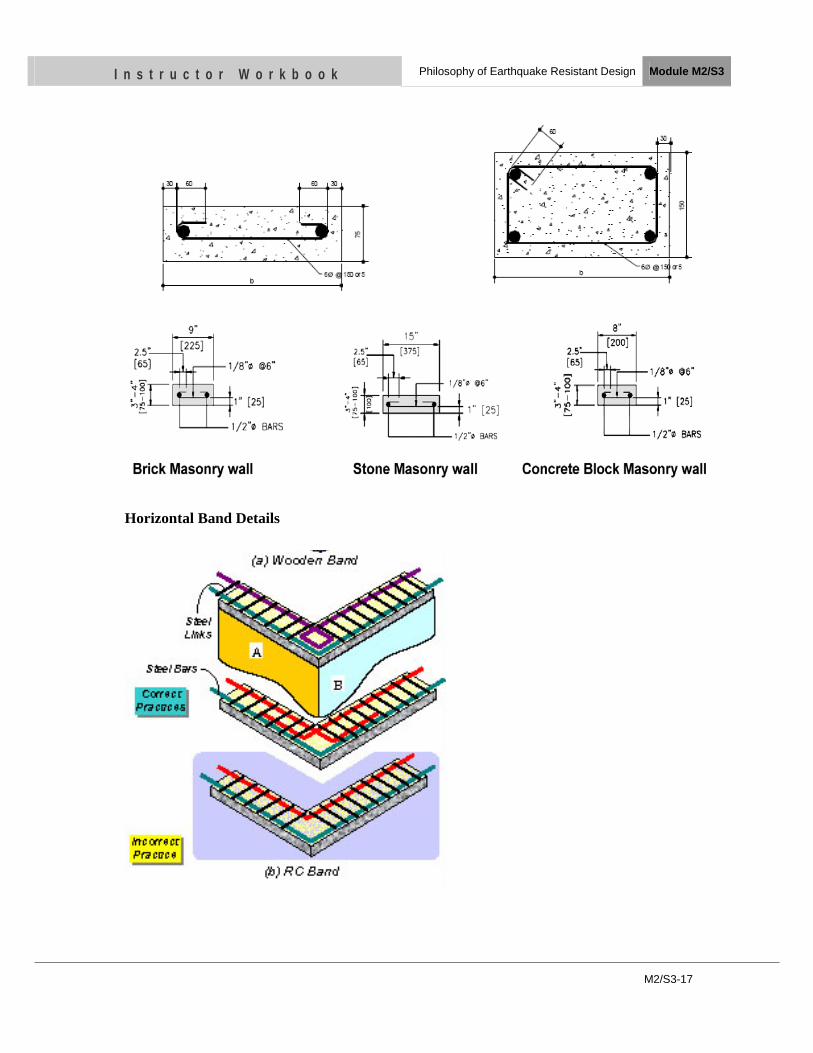
M2/S3-17
I n s t r u c t o r W o r k b o o k Philosophy of Earthquake Resistant Design Module M2/S3
Horizontal Band Details
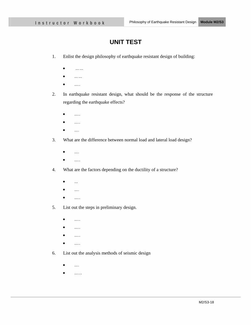
M2/S3-18
I n s t r u c t o r W o r k b o o k Philosophy of Earthquake Resistant Design Module M2/S3
UNIT TEST
1. Enlist the design philosophy of earthquake resistant design of building:
• ……
• ……
• …..
2. In earthquake resistant design, what should be the response of the structure
regarding the earthquake effects?
• …..
• …..
• ….
3. What are the difference between normal load and lateral load design?
• ….
• …..
4. What are the factors depending on the ductility of a structure?
• …
• ….
• …..
5. List out the steps in preliminary design.
• …..
• …..
• …..
• …..
6. List out the analysis methods of seismic design
• ….
• …...
OBJECTIVES
As a result of this session, you should be able to:
• Identify the building morphology and the seismic performance
• Define the seismic joints and its importance
• Discuss the importance of layout of structural elements.
Instructor Workbook Module M2/ S4
Consideration for appropriate Building Configuration
CONTENTS
1 Introduction ...................................................................................................... 1 2 BUILDING MORPHOLOGY AND SEISMIC PERFORMANCES .......... 2
2.1 Dimensions ............................................................................................... 2
2.2 Shape and Regularity ................................................................................ 3
3 Seismic Joints .................................................................................................... 6
3.1 TRADITIONAL USE OF SEISMIC JOINTS .......................................... 6
3.2 LOCATION OF SEISMIC JOINTS ......................................................... 7
3.3 WIDTH OF SEISMIC JOINTS ................................................................ 8
4 Structural Elements and their Layout ........................................................... 8
M2/S4-1
I n s t r u c t o r W o r k b o o k Consideration for Appropriate Building Configuration Module M2/S4
1 INTRODUCTION
During building design, engineers shall give attention to the most appropriate structural
configurations, taking into account the innovative seismic protection systems, and to develop
a methodology for building's seismic design based on the study of the main factors, both
architectural and structural, which influence the seismic response of buildings.
New globally oriented design methods and construction techniques have been devised in
recent years to improve the seismic safety of buildings. Seismic design must consider the
system ability to dissipate energy and the effects of the lateral deformation on the response of
the entire building. Two fundamental principles regarding the characteristics buildings and
their resistance to seismic events has been recognized for masonry buildings. The first is the
morphological and constructive regularity, with homogeneous and uninterrupted
passageways, which are capable of directing and opportunely involving the actions induced
by the earthquake. The second consists of the correct use of materials, which can make the
walls adequately resistant to the solicitations produced by the horizontal actions of the
building. These design criteria, singularly present or synergistically coexisting, are the main
reason that many ancient buildings are still standing and continue to be the two fundamental
principles for the sound design and construction of buildings with bearing walls in seismic
areas. Studies on the effects produced by numerous earthquakes have confirmed how much of
the damage and subsequent building collapses can be attributed to a structure’s irregular
configuration and morphology.
This can be considered as the result of the current design practice in which the architectural
design comes before the structure: in fact, the architectural conception (intended as the
definition of the formal, aesthetic and layout aspects), inexorably conditions the configuration
of the seismic resistant structural system. In fact the structural dimensioning of an already
defined morphological system results in it being a less trustworthy system, leading to a
structure that is more vulnerable to seismic damage. The problem involves the existing
relationship between architectural and structural design. Aseismic architectural morphology
includes not only the form and the dimensions of the building but also the nature, the
“regularity”, and most importantly the articulation of its structural and non-structural
M2/S4-2
I n s t r u c t o r W o r k b o o k Consideration for Appropriate Building Configuration Module M2/S4
elements (C. Arnold et. al, 1982). The term “regularity” does not mean symmetric and
repetitive solutions bound by a strict regimen of rules, but the search for solutions suitable to
a building’s seismic behaviors that are in harmony with technological innovations. The above
listed considerations involve both the morphological and structural configurations of
buildings, but so far they have not significantly influenced the fundamental concepts guiding
the architectural design and in current practice one cannot substantiate the existence – and
correct application – of clear guidelines of seismic architecture. This lack becomes even more
pronounced when new conceptions of structural design and the related innovative techniques
are adopted. The aspects regarding the morphological design and the definition of the
structural configuration must be studied in depth, in order to establish a hierarchic definition
of the most appropriate seismic configurations. The basic idea is that some essential
characteristics, like volumetric irregularity, non-homogeneous materials, lack of symmetry,
alignment, recurrent shape, usually considered non appropriate, on the contrary have to be
suitably used to achieve damping effects and energy dissipation. Thus the geometry of the
building shall be studied which includes an investigation of: (1) Symmetry (2) Continuity of
the resisting elements (3) Distribution of mass (4) Dimensions. The matter of dimensions
refers not only to the location of the building in the site but also to the size of elements and to
their arrangement in the building system as well as their relative position and the locations of
the centers of mass and rigidity.
2 BUILDING MORPHOLOGY AND SEISMIC PERFORMANCES
2.1 Dimensions Since the beginning of the study of the building behavior under seismic attacks, the shape has
been recognized as a fundamental parameter in controlling their response. At a first stage the
attention was focused on the global dimensions of the buildings, so we find limitations on
building dimensions in the first prescriptions regarding the constructions in earthquake prone
zones. The three fundamental aspects are the influence of the soil, the construction details and
the dimensions of the buildings. Strong limitations were provided on building height in past
days. But it has been recognized that the height is not, in itself, a negative factor for the
M2/S4-3
I n s t r u c t o r W o r k b o o k Consideration for Appropriate Building Configuration Module M2/S4
seismic response (C. Arnold et. al, 1982). In fact, a greater height can increase the natural
period of the building shifting it in the range where the response amplification is lower. On
the contrary, the ratio height/width, that is a shape factor, has to be controlled because it
influences the overturning of the building and the axial overloading of the external structural
elements.
It is evident from the past earthquakes that with increasing height of a building, although all
other factors are equal, earthquake resisting problem increase exponentially. It is because the
horizontal movement of the floors during ground shaking is large in slender buildings.
Further, large building height causes large overturning moments during an earthquake. If
building is slender, it leads to high compressive and tensile forces on outer columns, which
leads to rapid strength and stiffness degradation of these columns. So it is advised to keep
slenderness of the building within 3.
Similarly in narrow but very long buildings, the ground imparts very different earthquake
vibration to the various parts of the building causing severe damage to it. So it is advisable to
keep length to width ratio within 3. If the ratio is larger, it is better to subdivide the building
into parts keeping the ratio three or less. However, it should not mean a building with length
to width ratio less than 3 but very large in plan is good from earthquake point of view. When
the plan becomes extremely large, the building, even symmetrical and of simple shape, can
have trouble responding as one unit to ground motion because earthquake moves as waves
through the earth’s crust. If the building has great horizontal dimensions, the differential
arrival of the wave in different parts of the building might pose problems. So it is advised to
subdivide the building in parts keeping the largest length to 30m unless special analysis is not
conducted.
2.2 Shape and Regularity Building shape is important because it has a decisive influence on the dynamic behavior
(inverse pendulum, soft story, torsion effects) and on the stress concentration (variations of
vertical and horizontal shape). The geometric parameters qualifying the building shape,
commonly referred to as influence parameters of the seismic behavior, are the vertical and
plan regularity, the symmetry and the compactness. The global shape irregularity can be a
M2/S4-4
I n s t r u c t o r W o r k b o o k Consideration for Appropriate Building Configuration Module M2/S4
negative factor in itself largely because it affects the structural system. Irregularities in the
seismic resistant system are determinant in reducing the good performance under seismic
attack. Buildings with simple geometry and symmetry in plan and elevation are good from
earthquake resistant point of view. Building with reentrant corners like U, L, V, H and +
shape in plan suffer more damage during an earthquake. These plan shapes produce variation
in stiffness and hence differential motions among different parts of the building resulting in
local stress concentration at the reentrant corner. The other problem caused by this is torsion
in horizontal plane. In this case is the stiffness and mass center do not coincide geometrically
and thus results in twisting of the building in plan. The twisting effect causes higher shear
load on far distant columns and walls forcing them to fail. Further, it tends to distort the form
in the way that will vary in nature and magnitude depending on the nature and direction of
the ground motion, length of wings and their aspect ratio, height of the wings and their
slenderness. The adverse effect of these entrant corners in the plan of buildings can be
avoided by sub-dividing the buildings into small simple rectangular sub divisions e.g. a +
shaped building can be sub divided into three or more parts providing gap between them. It
allows the separated blocks to oscillate independently during earthquakes. However, if the
horizontal projections are les than 1/4th of the side, sub-division is not necessary.
Most classical torsional problems are shop/open front of corner building where
architecturally the building may look symmetrical but the structure could be facing severe
stiffness discontinuity problem, far apart from mass and stiffness centers. It could become
major source of torsional activity in the building leading to failure of corner part of the
building. The problem of open front can be solved by providing stiff diaphragm and small
return wall in case of small building and providing stiff columns at open front.
Vertical irregularities do not only consist of irregular vertical geometry (30% variation of the
horizontal dimension at any story), but also of irregularities of the structural system: stiffness
discontinuity (soft story), weight irregularity, discontinuity of vertical lateral force resisting
elements, strength discontinuity (weak story). Plan irregularities also consist of both
geometric (reentrant corners, diaphragm discontinuity) and structural irregularities (torsional
effects, vertical lateral load-resisting elements discontinuous or not parallel to or symmetric
about the major axes).
M2/S4-5
I n s t r u c t o r W o r k b o o k Consideration for Appropriate Building Configuration Module M2/S4
The earthquake forces developed at different floor levels in a building should be transferred
to the ground through the shortest and the most direct path. Any deviation or discontinuity in
this load path results in poor performance of the building. Buildings with discontinuous
columns, floating columns and vertical setbacks cause a sudden leap in earthquake force at
the point of discontinuity and deformation incompatibility. Buildings with columns which do
not go to the foundation but hang or float on beams at an intermediate storey have
discontinuous load path. Further, the setbacks cause severe twisting of the building causing
distress in the structural elements. These situations should be avoided. It means the building
should have uniform stiffness along the height. A building could be symmetrical in plan but it
still could be tortionally active if it is standing on a sloping ground. Buildings on sloping
ground could have unequal height columns or walls across the slope, which causes shift of
stiffness center towards short column and consequently causing twist in the building and
cause damage in the longer columns. Building on sloping ground suffered severe destruction
during South Asian Earthquake of 8 October 2005. The problem can be solved either by a
bench cutting and providing foundation at the same level keeping the column height same or
providing stiff walls along the longer columns and sides.
Failure of buildings due to soft storey in ground floor in RC frame buildings was one of the
common scenes in Bhuj earthquake. Soft storey was even observed in masonry building
during that time. A soft storey is created in multi storey buildings due to sudden change in
stiffness along the height. The desire for higher storey height in first storey than in the upper
storey and/or more open spaces in the first storey as compared to upper storey which are
filled with walls for rooms causes laterally very stiff and strong storey above the flexible
storey. During earthquake, all the displacement of the building is concentrated in the first
storey, forcing columns to fail.
The staircase failure is common during an earthquake in the structures where landing beams
are connected to the column resulting shortened column height and the column becomes
stiffer than other full height columns. Such provision attracts more earthquake loads which
force them to fail. Other situation where a short column effect arises is where a part of
column is entrapped by infill walls; columns support mezzanine floors or loft slabs are added
between two regular floors. Short column situation arises when the building with different
M2/S4-6
I n s t r u c t o r W o r k b o o k Consideration for Appropriate Building Configuration Module M2/S4
column heights on sloping ground suffer earthquake across the slope. The short column effect
should be avoided as far as possible during architectural planning of the building. If it cannot
be avoided, it should be well addressed during structural analysis and design phase
considering infill walls. The problem can be mitigated by providing closely spaced confining
stirrups along the full height of the column.
3 SEISMIC JOINTS Seismic joints occur naturally when one building is built adjacent to another, whether or not
the buildings are linked functionally. Seismic joints are also frequently introduced to separate
wings, or other parts of a single building. A seismic joint typically creates a separation
between the adjacent buildings or parts of buildings that include separation of walls, floors,
and roof. In case of joints within the same building which may include separation, or
accommodation for movement of piping, HVAC ducts, and other elements that have a
functional need to cross the joint. The design of seismic joints is complex and includes efforts
to assure that the joint is properly sized, adequately sealed from weather and safe to walk on
and provides for adequate movement of other systems crossing the joint and means to
maintain the fire ratings of the floor, roof and wall systems. Construction of such joints is
costly and architecturally undesirable, so they should be incorporated with carefulness.
3.1 TRADITIONAL USE OF SEISMIC JOINTS The earliest use of seismic joints did not recognize them as joints at all. They were merely the
space between adjacent buildings. As structural engineers in seismically active areas thought
more about the lateral movements of buildings in seismic events, they began to develop rules
of thumb (such as 2 inches per floor) for deciding how wide seismic joints should be. They
studied earthquake damage and began to see evidence that buildings had collided and that
sometimes very serious damage had occurred. Particularly serious damage sometimes
resulted when floors of adjacent buildings did not align, or when one building was much
taller than the other. As seismic analysis evolved to the level of the static analysis methods of
the 1950’s and 60’s, structural engineers began to recognize that certain building shapes
resulted in potentially undesirable effects, such as torsion or high collector forces at reentrant
corners, that their analysis methods were not yet adequate to deal with. It became a common
M2/S4-7
I n s t r u c t o r W o r k b o o k Consideration for Appropriate Building Configuration Module M2/S4
practice to introduce seismic joints to divide a complexly shaped building into a group of
smaller buildings with simple shapes that were easy to analyze and had predictable seismic
performance. For example, an L-shaped building was often divided into two rectangles.
Another place where seismic joints have often been introduced is at locations where
diaphragms are recognized to be weak, and it is felt to be better to introduce a joint than to
suffer the damage that might occur during a seismic event. This is somewhat similar to the
practice of introducing joints in sidewalks where they get narrower or change direction. A
typical example where this might occur would be in the somewhat common H-shaped
building, when the elevators and stairs are located in the narrow crossbar of the H.
Seismic joints are similar to expansion joints, but at the same time very different. Expansion
joints are introduced to accommodate building movements caused by shrinkage, creep, or
temperature changes. They are often one-way joints, that is, they are primarily intended to
accommodate movements in the direction perpendicular to the joint. Expansion joints are also
commonly placed at some regular interval of length based on the expected rate of shrinkage
or temperature movement expected to occur over the building length. Seismic joints, on the
other hand, must accommodate movement in both orthogonal directions simultaneously and
their spacing is not typically affected by building length or size.
3.2 LOCATION OF SEISMIC JOINTS When seismic joints are determined to be necessary or desirable for a particular building, the
locations of the joints are often obvious and inherent. Often these inherent locations are also
the most desirable from the standpoint of mitigating the appearance and cost of the joints. For
example, if a joint is introduced because elevators, stairs, mechanical shafts and other floor
openings conspire to so weaken the diaphragm that a joint is deemed necessary, the beneficial
result is that there is very little floor area through which the joint needs to traverse. The
various shafts and floor openings can be incorporated as part of the joint and only the narrow
area of floor remaining (usually a corridor) requires an expensive joint cover. Similarly,
joints that may be employed at reentrant corners and comparable locations have the
advantage of being relatively easy to conceal in the exterior wall. Where there are several
M2/S4-8
I n s t r u c t o r W o r k b o o k Consideration for Appropriate Building Configuration Module M2/S4
possible joint locations that would satisfy the functional purpose of the joint, similar
considerations to the above should govern the choice of location and path of the joint.
3.3 WIDTH OF SEISMIC JOINTS The width of seismic joints in modern buildings can vary from just a few inches to several
feet, depending on building height and stiffness. Joints in more modern buildings tend to be
much wider than their similar predecessors. The contributing factors are the lower lateral
stiffness of many modern buildings, and the greater recognition by engineers of the
magnitude of real lateral deformations. It is instructive to review the history of drift
calculations and seismic joint width from the perspective of code development.
4 STRUCTURAL ELEMENTS AND THEIR LAYOUT When creating a frame building, the columns should be uniformly distributed and these
should be well framed up with the beams in both the orthogonal directions with uniform
spans as it improves building’s torsional performance and helps to make similar stiffness in
both directions. Furthermore, it is advisable to keep column wider than the beam. There will
be an enhanced torsional resistance of the building when we provide stiffer elements such as
walls or bracings along the periphery rather than to concentrate them in central part of the
building, regardless of the structural system. The eccentricity in beam column joints, sudden
change in stiffness of beams or columns, same width of beam column should be avoided for
better performance of the building. A problem arises when the width of beam and column are
of same size that the beam reinforcements have to either goggle or these should pass outside
of the beam-column joint. If these are goggled, during an earthquake, beam reinforcement
would try to straighten itself under tension and would create additional stress on the column
bars and force them to buckle. If the bars are provided outside the beam-column joint, during
earthquake vibration, the cover of column would fall down leading to reduced beam capacity
because of failed anchorage of the beam bars. The recommended practice is to provide
column at least 75mm wider than the beam but column width should not be less than 300mm.
M2/S4-9
I n s t r u c t o r W o r k b o o k Consideration for Appropriate Building Configuration Module M2/S4
UNIT TEST
1. Name the building morphologies affecting in the seismic performance.
• …..
• …..
2. Why seismic joints are necessary?
• …..
3. What are factors affecting the width of the seismic joints?
• …..
• …...
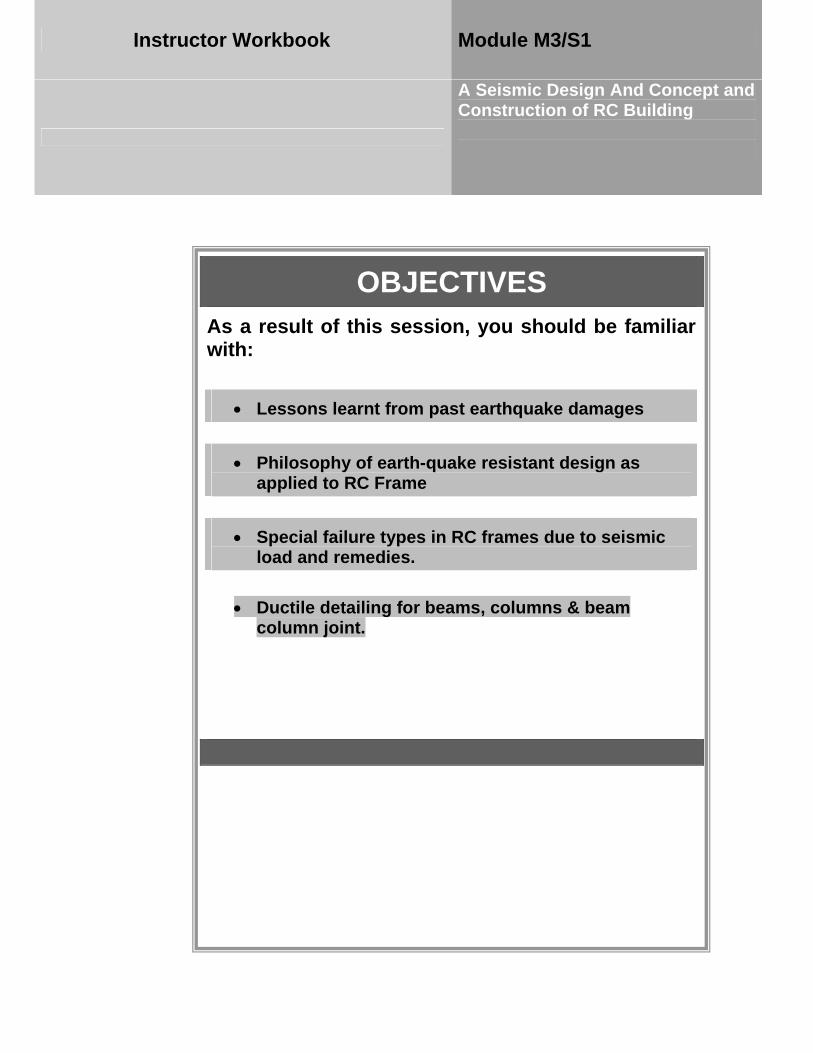
OBJECTIVES As a result of this session, you should be familiar with:
•• LLeessssoonnss lleeaarrnntt ffrroomm ppaasstt eeaarrtthhqquuaakkee ddaammaaggeess
• PPhhiilloossoopphhyy ooff eeaarrtthh--qquuaakkee rreessiissttaanntt ddeessiiggnn aass aapppplliieedd ttoo RRCC FFrraammee
• SSppeecciiaall ffaaiilluurree ttyyppeess iinn RRCC ffrraammeess dduuee ttoo sseeiissmmiicc llooaadd aanndd rreemmeeddiieess..
•• DDuuccttiillee ddeettaaiilliinngg ffoorr bbeeaammss,, ccoolluummnnss && bbeeaamm ccoolluummnn jjooiinntt..
Instructor Workbook Module M3/S1
A Seismic Design And Concept and Construction of RC Building
I n s t r u c t o r W o r k b o o k A seismic Design Concept and Construction of RC Building
Module M3/S1
ii
CONTENTS
1. Introduction ................................................................................................1 2. Lessons learnt from past earthquake damages .......................................1 3. Philosophy of earth-quake resistant design as applied to RC Frame ....6 4. Special failure types in RC frames due to seismic load and remedies ...8
4.1 Strong-Column weak beam ................................................................8
4.2 Torsion in building ..............................................................................9
4.3 Soft storey .........................................................................................12
4.4 Short Column ....................................................................................15
4.5 Infill walls .........................................................................................17
4.6 Hammering .......................................................................................20
4.7 Cold joint ..........................................................................................22
5. Our Practice for Ductile Detailing ..........................................................23 6. Ductile Detailing for Beam, Column and Beam-Column Joint ...........28
I n s t r u c t o r W o r k b o o k A Seismic Design Concept and Construction of RC Building
Module M3/S1
M3/S1-1
1. Introduction
The conceptual design and the detailing of the structural elements (walls, columns, slabs) and the non-structural elements (partition walls, façades) play a central role in determining the structural behavior (before failure) and the errors and defects in the conceptual design cannot be compensated by following calculations and detailed design by the engineer. A seismically correct conceptual design is furthermore necessary in order to achieve a good earthquake resistance without incurring significant additional costs. A typical Reinforcement Concrete (RC) building is made of horizontal members (beams and slabs) and vertical members (columns and walls), and supported by foundations that rest on ground. The system comprising of RC columns and connecting beams is called a RC Frame. The RC frame participates in resisting the earthquake forces. Earthquake shaking generates inertia forces in the building, which are proportional to the building mass. Since most of the building mass is present at floor levels, earthquake-induced inertia forces primarily develop at the floor levels. These forces travel downwards through slab and beams to columns and walls, and then to the foundations from where they are dispersed to the ground. As inertia forces accumulate downwards from the top of the building, the columns and walls at lower storey experience higher earthquake-induced forces.
2. Lessons learnt from past earthquake damages
First of all we will discuss about global damage to the RC framed construction and then move to local damage. After that we will discuss why these damages occurred and what the problem was. It will help us to learn many lessons.
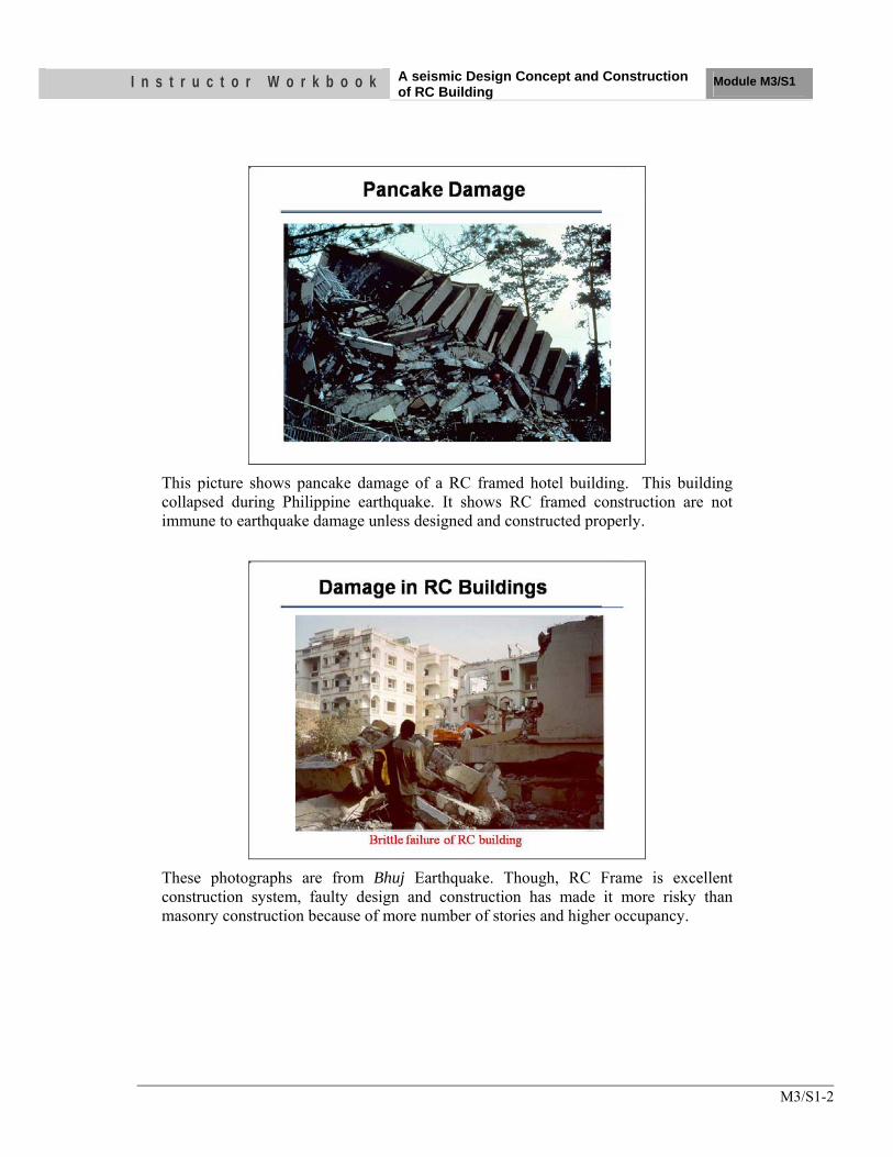
I n s t r u c t o r W o r k b o o k A seismic Design Concept and Construction of RC Building
Module M3/S1
M3/S1-2
This picture shows pancake damage of a RC framed hotel building. This building collapsed during Philippine earthquake. It shows RC framed construction are not immune to earthquake damage unless designed and constructed properly.
These photographs are from Bhuj Earthquake. Though, RC Frame is excellent construction system, faulty design and construction has made it more risky than masonry construction because of more number of stories and higher occupancy.
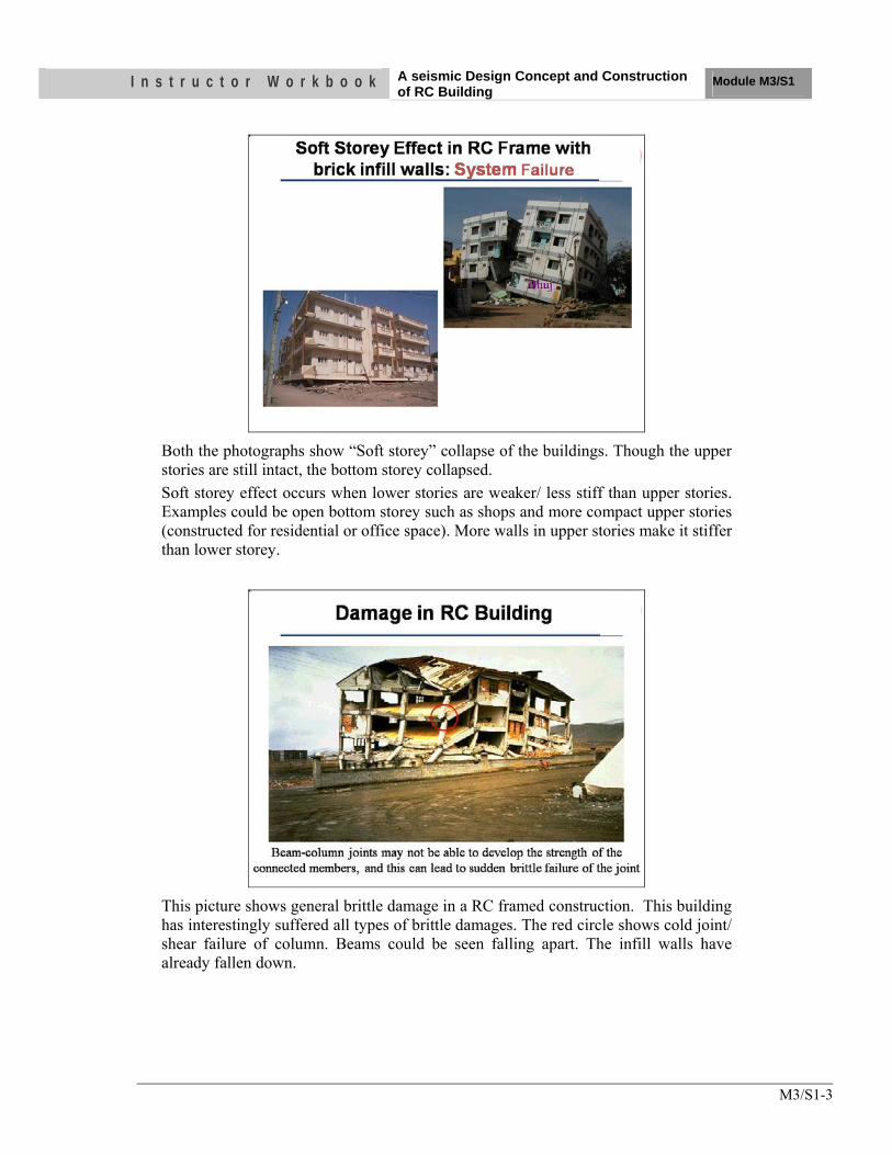
I n s t r u c t o r W o r k b o o k A seismic Design Concept and Construction of RC Building
Module M3/S1
M3/S1-3
Both the photographs show “Soft storey” collapse of the buildings. Though the upper stories are still intact, the bottom storey collapsed. Soft storey effect occurs when lower stories are weaker/ less stiff than upper stories. Examples could be open bottom storey such as shops and more compact upper stories (constructed for residential or office space). More walls in upper stories make it stiffer than lower storey.
This picture shows general brittle damage in a RC framed construction. This building has interestingly suffered all types of brittle damages. The red circle shows cold joint/ shear failure of column. Beams could be seen falling apart. The infill walls have already fallen down.
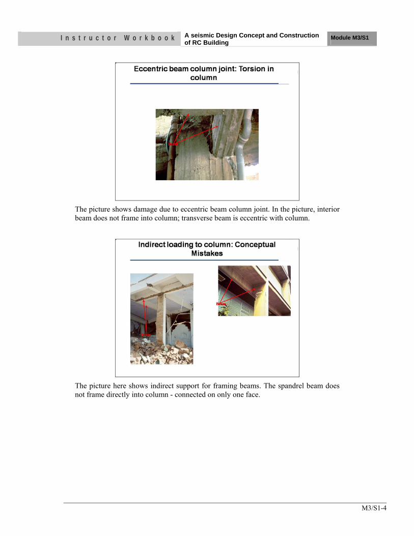
I n s t r u c t o r W o r k b o o k A seismic Design Concept and Construction of RC Building
Module M3/S1
M3/S1-4
The picture shows damage due to eccentric beam column joint. In the picture, interior beam does not frame into column; transverse beam is eccentric with column.
The picture here shows indirect support for framing beams. The spandrel beam does not frame directly into column - connected on only one face.
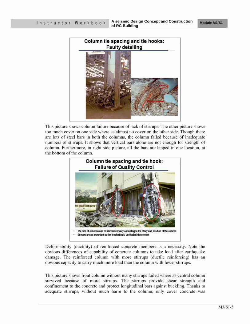
I n s t r u c t o r W o r k b o o k A seismic Design Concept and Construction of RC Building
Module M3/S1
M3/S1-5
This picture shows column failure because of lack of stirrups. The other picture shows too much cover on one side where as almost no cover on the other side. Though there are lots of steel bars in both the columns, the column failed because of inadequate numbers of stirrups. It shows that vertical bars alone are not enough for strength of column. Furthermore, in right side picture, all the bars are lapped in one location, at the bottom of the column.
Deformability (ductility) of reinforced concrete members is a necessity. Note the obvious differences of capability of concrete columns to take load after earthquake damage. The reinforced column with more stirrups (ductile reinforcing) has an obvious capacity to carry much more load than the column with fewer stirrups. This picture shows front column without many stirrups failed where as central column survived because of more stirrups. The stirrups provide shear strength and confinement to the concrete and protect longitudinal bars against buckling. Thanks to adequate stirrups, without much harm to the column, only cover concrete was
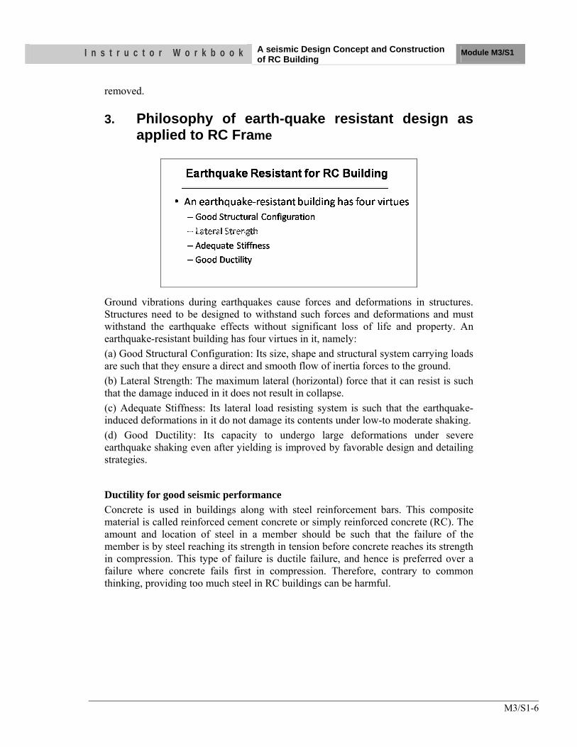
I n s t r u c t o r W o r k b o o k A seismic Design Concept and Construction of RC Building
Module M3/S1
M3/S1-6
removed.
3. Philosophy of earth-quake resistant design as applied to RC Frame
Ground vibrations during earthquakes cause forces and deformations in structures. Structures need to be designed to withstand such forces and deformations and must withstand the earthquake effects without significant loss of life and property. An earthquake-resistant building has four virtues in it, namely: (a) Good Structural Configuration: Its size, shape and structural system carrying loads are such that they ensure a direct and smooth flow of inertia forces to the ground. (b) Lateral Strength: The maximum lateral (horizontal) force that it can resist is such that the damage induced in it does not result in collapse. (c) Adequate Stiffness: Its lateral load resisting system is such that the earthquake-induced deformations in it do not damage its contents under low-to moderate shaking. (d) Good Ductility: Its capacity to undergo large deformations under severe earthquake shaking even after yielding is improved by favorable design and detailing strategies.
Ductility for good seismic performance Concrete is used in buildings along with steel reinforcement bars. This composite material is called reinforced cement concrete or simply reinforced concrete (RC). The amount and location of steel in a member should be such that the failure of the member is by steel reaching its strength in tension before concrete reaches its strength in compression. This type of failure is ductile failure, and hence is preferred over a failure where concrete fails first in compression. Therefore, contrary to common thinking, providing too much steel in RC buildings can be harmful.
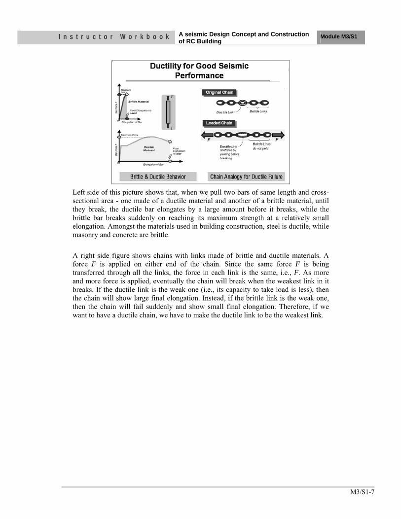
I n s t r u c t o r W o r k b o o k A seismic Design Concept and Construction of RC Building
Module M3/S1
M3/S1-7
Left side of this picture shows that, when we pull two bars of same length and cross-sectional area - one made of a ductile material and another of a brittle material, until they break, the ductile bar elongates by a large amount before it breaks, while the brittle bar breaks suddenly on reaching its maximum strength at a relatively small elongation. Amongst the materials used in building construction, steel is ductile, while masonry and concrete are brittle. A right side figure shows chains with links made of brittle and ductile materials. A force F is applied on either end of the chain. Since the same force F is being transferred through all the links, the force in each link is the same, i.e., F. As more and more force is applied, eventually the chain will break when the weakest link in it breaks. If the ductile link is the weak one (i.e., its capacity to take load is less), then the chain will show large final elongation. Instead, if the brittle link is the weak one, then the chain will fail suddenly and show small final elongation. Therefore, if we want to have a ductile chain, we have to make the ductile link to be the weakest link.
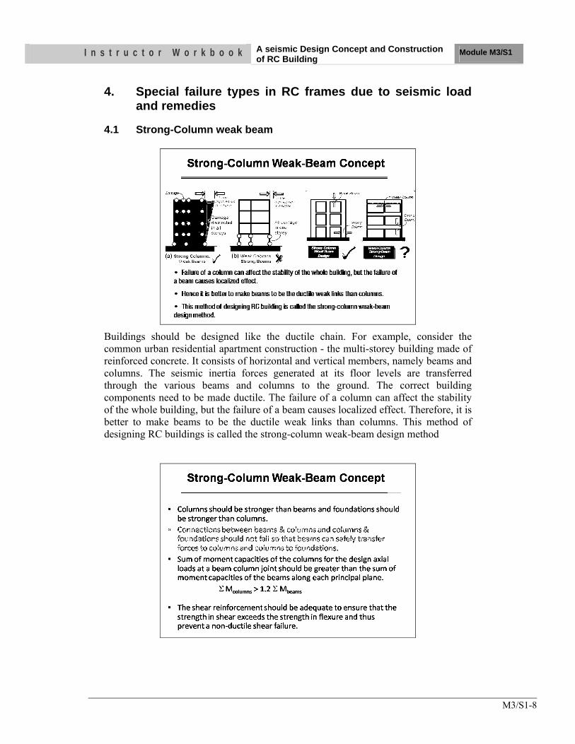
I n s t r u c t o r W o r k b o o k A seismic Design Concept and Construction of RC Building
Module M3/S1
M3/S1-8
4. Special failure types in RC frames due to seismic load and remedies
4.1 Strong-Column weak beam
Buildings should be designed like the ductile chain. For example, consider the common urban residential apartment construction - the multi-storey building made of reinforced concrete. It consists of horizontal and vertical members, namely beams and columns. The seismic inertia forces generated at its floor levels are transferred through the various beams and columns to the ground. The correct building components need to be made ductile. The failure of a column can affect the stability of the whole building, but the failure of a beam causes localized effect. Therefore, it is better to make beams to be the ductile weak links than columns. This method of designing RC buildings is called the strong-column weak-beam design method
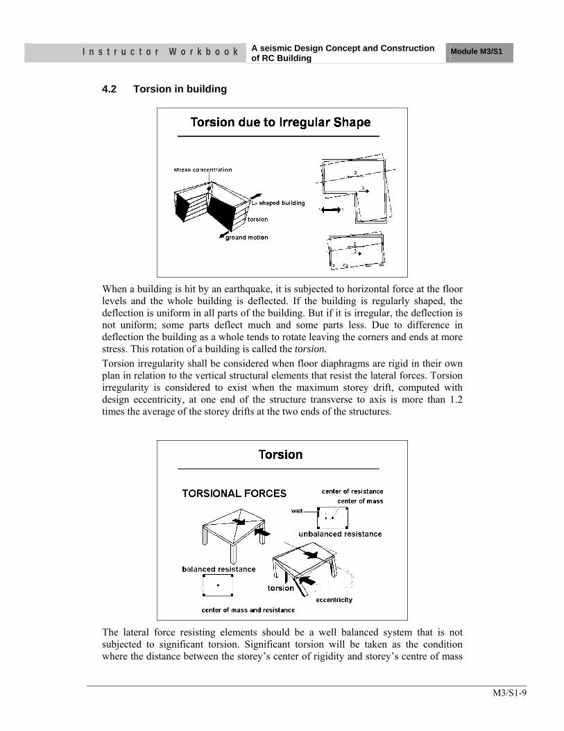
I n s t r u c t o r W o r k b o o k A seismic Design Concept and Construction of RC Building
Module M3/S1
M3/S1-9
4.2 Torsion in building
When a building is hit by an earthquake, it is subjected to horizontal force at the floor levels and the whole building is deflected. If the building is regularly shaped, the deflection is uniform in all parts of the building. But if it is irregular, the deflection is not uniform; some parts deflect much and some parts less. Due to difference in deflection the building as a whole tends to rotate leaving the corners and ends at more stress. This rotation of a building is called the torsion. Torsion irregularity shall be considered when floor diaphragms are rigid in their own plan in relation to the vertical structural elements that resist the lateral forces. Torsion irregularity is considered to exist when the maximum storey drift, computed with design eccentricity, at one end of the structure transverse to axis is more than 1.2 times the average of the storey drifts at the two ends of the structures.
The lateral force resisting elements should be a well balanced system that is not subjected to significant torsion. Significant torsion will be taken as the condition where the distance between the storey’s center of rigidity and storey’s centre of mass
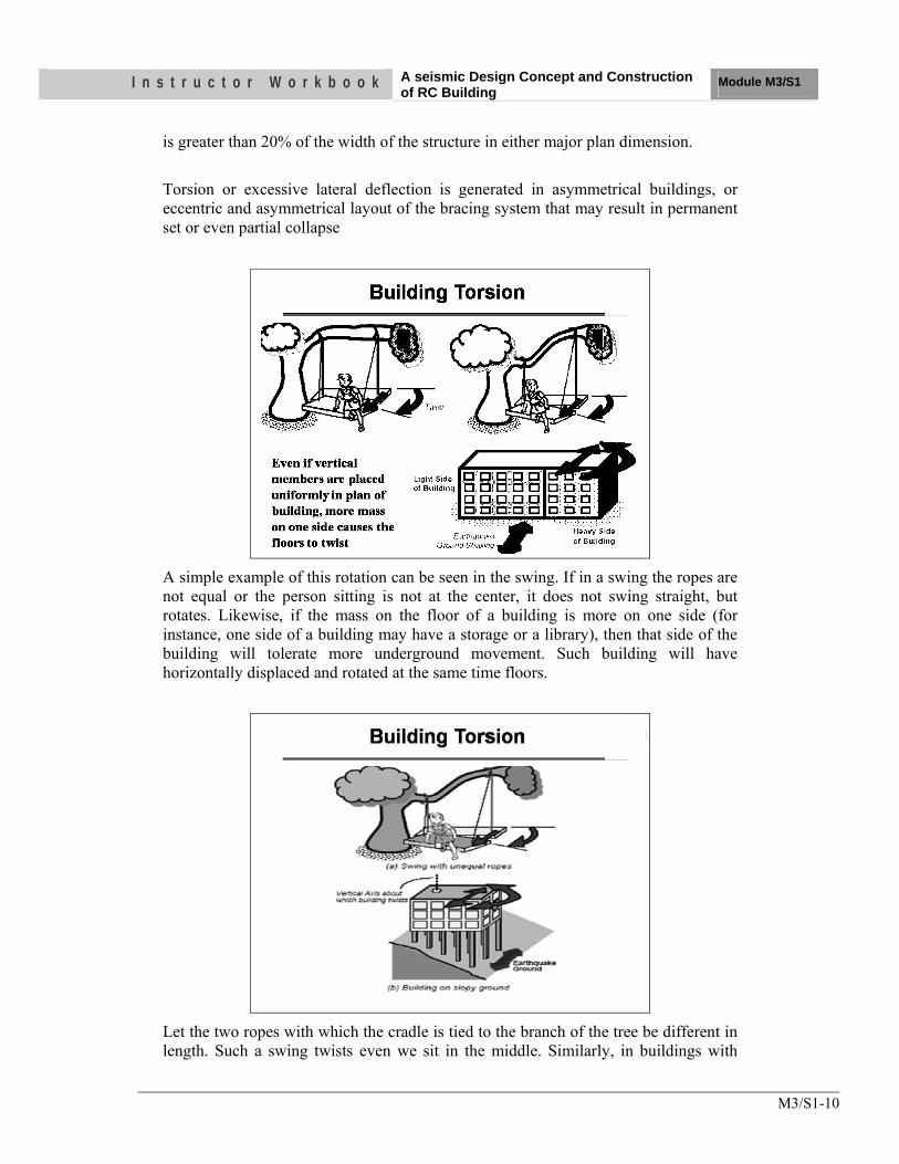
I n s t r u c t o r W o r k b o o k A seismic Design Concept and Construction of RC Building
Module M3/S1
M3/S1-10
is greater than 20% of the width of the structure in either major plan dimension. Torsion or excessive lateral deflection is generated in asymmetrical buildings, or eccentric and asymmetrical layout of the bracing system that may result in permanent set or even partial collapse
A simple example of this rotation can be seen in the swing. If in a swing the ropes are not equal or the person sitting is not at the center, it does not swing straight, but rotates. Likewise, if the mass on the floor of a building is more on one side (for instance, one side of a building may have a storage or a library), then that side of the building will tolerate more underground movement. Such building will have horizontally displaced and rotated at the same time floors.
Let the two ropes with which the cradle is tied to the branch of the tree be different in length. Such a swing twists even we sit in the middle. Similarly, in buildings with
I n s t r u c t o r W o r k b o o k A seismic Design Concept and Construction of RC Building
Module M3/S1
M3/S1-11
unequal vertical members (i.e., columns and/or walls) the floors twist about a vertical axis and displace horizontally.
Likewise, buildings, which have walls only on two sides (or one side) and thin columns along the other, twist when shaken at the ground level. Buildings that are of irregular shapes in plan tend to twist under earthquake shaking. For example, in a propped overhanging building, the overhanging portion swings on the relatively slender columns under it. The floors twist and displace horizontally.
Twist in buildings, called torsion by engineers, makes different portions at the same floor level to move horizontally by different amounts. This induces more damage in the columns and walls on the side that moves more. Many buildings have been severely affected by this excessive torsional behavior during past earthquakes. It is best to minimize (if not completely avoid) twist by ensuring that buildings have symmetry in plan (i.e., uniformly distributed mass and uniformly placed vertical
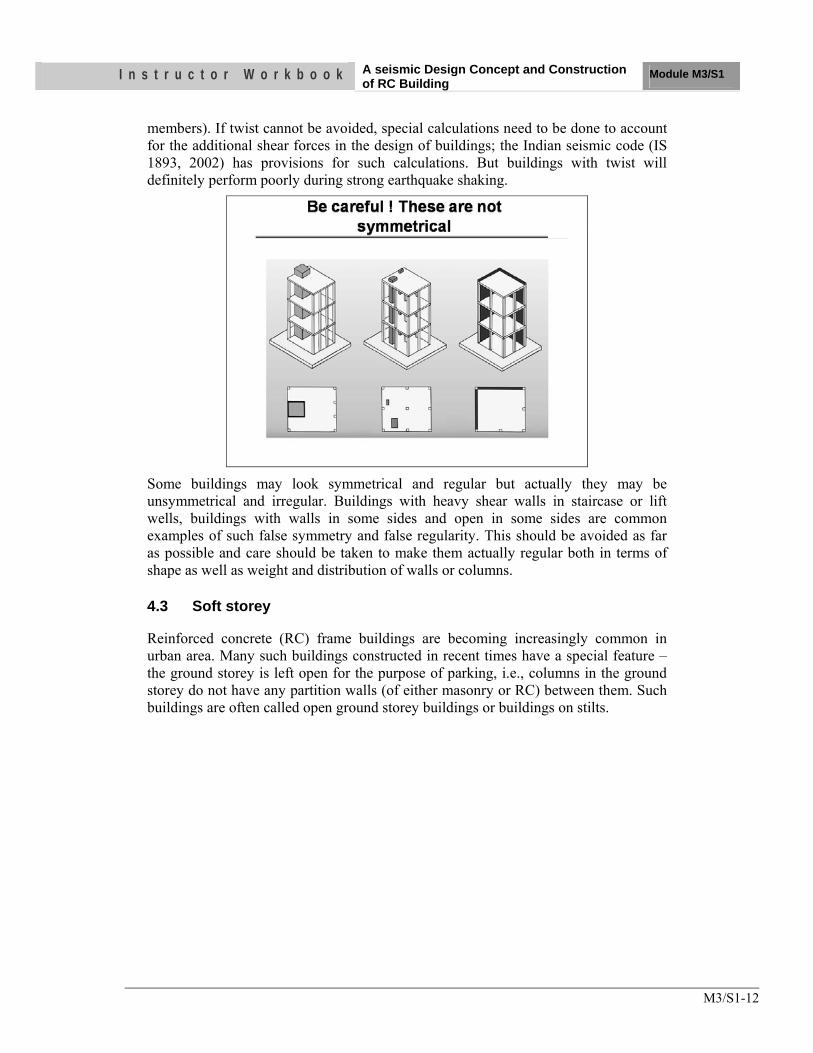
I n s t r u c t o r W o r k b o o k A seismic Design Concept and Construction of RC Building
Module M3/S1
M3/S1-12
members). If twist cannot be avoided, special calculations need to be done to account for the additional shear forces in the design of buildings; the Indian seismic code (IS 1893, 2002) has provisions for such calculations. But buildings with twist will definitely perform poorly during strong earthquake shaking.
Some buildings may look symmetrical and regular but actually they may be unsymmetrical and irregular. Buildings with heavy shear walls in staircase or lift wells, buildings with walls in some sides and open in some sides are common examples of such false symmetry and false regularity. This should be avoided as far as possible and care should be taken to make them actually regular both in terms of shape as well as weight and distribution of walls or columns.
4.3 Soft storey
Reinforced concrete (RC) frame buildings are becoming increasingly common in urban area. Many such buildings constructed in recent times have a special feature – the ground storey is left open for the purpose of parking, i.e., columns in the ground storey do not have any partition walls (of either masonry or RC) between them. Such buildings are often called open ground storey buildings or buildings on stilts.
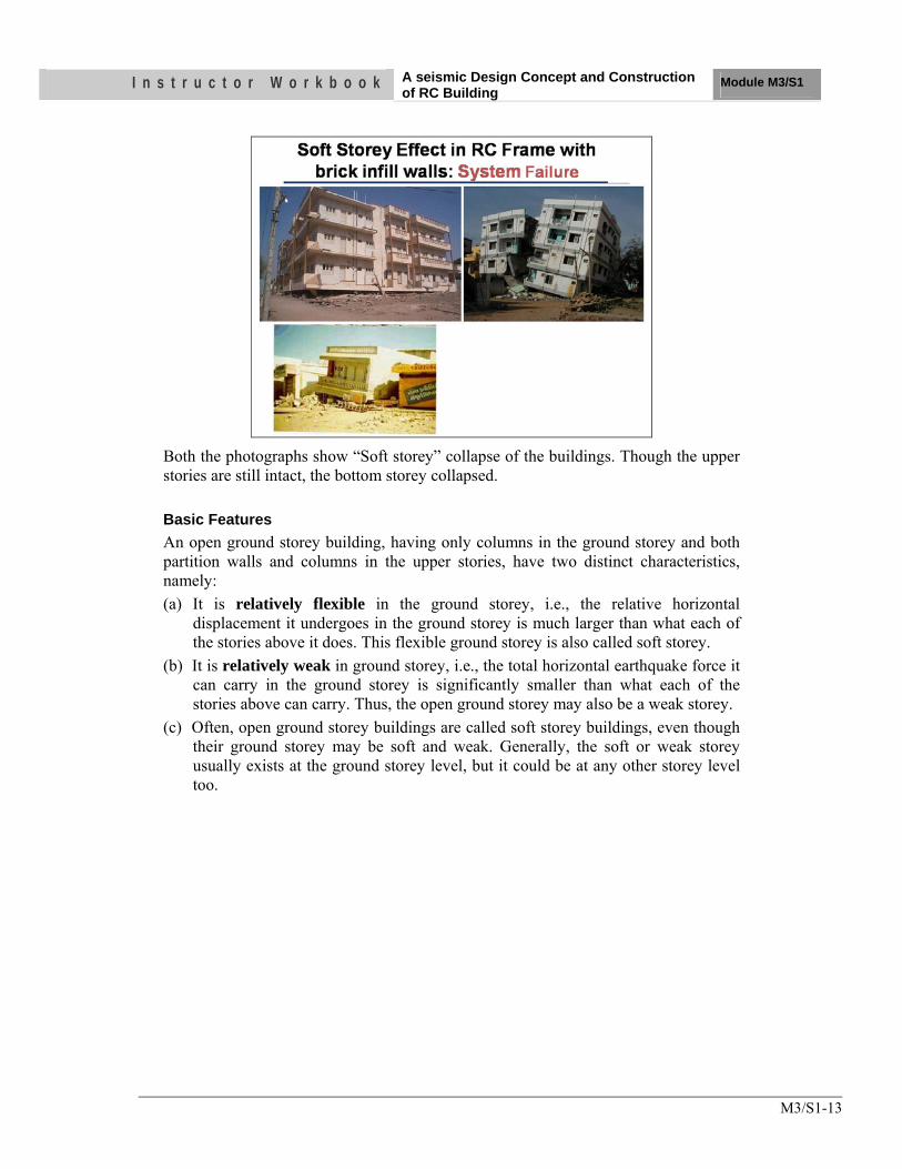
I n s t r u c t o r W o r k b o o k A seismic Design Concept and Construction of RC Building
Module M3/S1
M3/S1-13
Both the photographs show “Soft storey” collapse of the buildings. Though the upper stories are still intact, the bottom storey collapsed. Basic Features An open ground storey building, having only columns in the ground storey and both partition walls and columns in the upper stories, have two distinct characteristics, namely: (a) It is relatively flexible in the ground storey, i.e., the relative horizontal
displacement it undergoes in the ground storey is much larger than what each of the stories above it does. This flexible ground storey is also called soft storey.
(b) It is relatively weak in ground storey, i.e., the total horizontal earthquake force it can carry in the ground storey is significantly smaller than what each of the stories above can carry. Thus, the open ground storey may also be a weak storey.
(c) Often, open ground storey buildings are called soft storey buildings, even though their ground storey may be soft and weak. Generally, the soft or weak storey usually exists at the ground storey level, but it could be at any other storey level too.
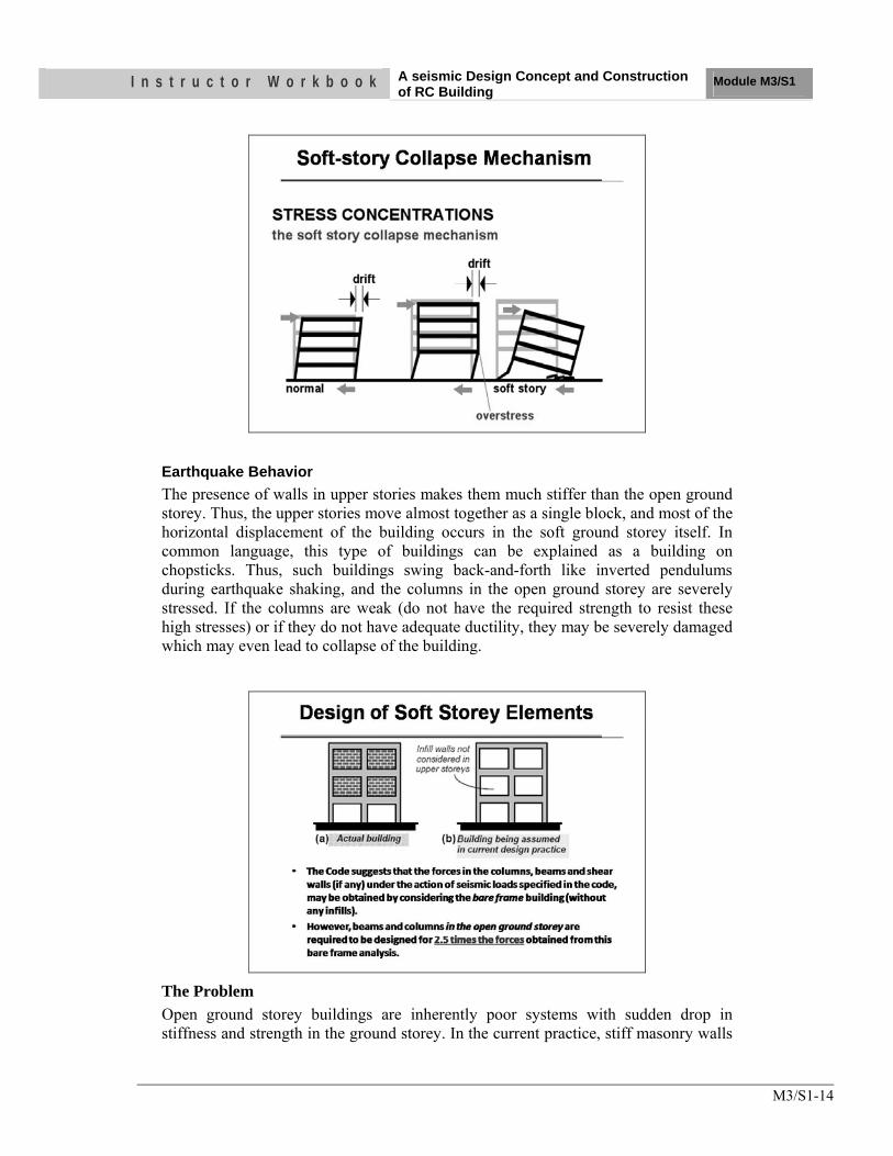
I n s t r u c t o r W o r k b o o k A seismic Design Concept and Construction of RC Building
Module M3/S1
M3/S1-14
Earthquake Behavior The presence of walls in upper stories makes them much stiffer than the open ground storey. Thus, the upper stories move almost together as a single block, and most of the horizontal displacement of the building occurs in the soft ground storey itself. In common language, this type of buildings can be explained as a building on chopsticks. Thus, such buildings swing back-and-forth like inverted pendulums during earthquake shaking, and the columns in the open ground storey are severely stressed. If the columns are weak (do not have the required strength to resist these high stresses) or if they do not have adequate ductility, they may be severely damaged which may even lead to collapse of the building.
The Problem Open ground storey buildings are inherently poor systems with sudden drop in stiffness and strength in the ground storey. In the current practice, stiff masonry walls
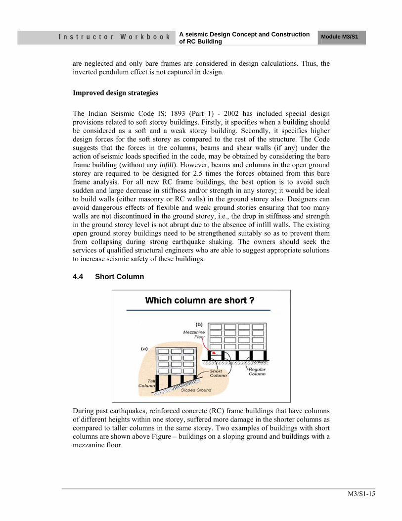
I n s t r u c t o r W o r k b o o k A seismic Design Concept and Construction of RC Building
Module M3/S1
M3/S1-15
are neglected and only bare frames are considered in design calculations. Thus, the inverted pendulum effect is not captured in design. Improved design strategies The Indian Seismic Code IS: 1893 (Part 1) - 2002 has included special design provisions related to soft storey buildings. Firstly, it specifies when a building should be considered as a soft and a weak storey building. Secondly, it specifies higher design forces for the soft storey as compared to the rest of the structure. The Code suggests that the forces in the columns, beams and shear walls (if any) under the action of seismic loads specified in the code, may be obtained by considering the bare frame building (without any infill). However, beams and columns in the open ground storey are required to be designed for 2.5 times the forces obtained from this bare frame analysis. For all new RC frame buildings, the best option is to avoid such sudden and large decrease in stiffness and/or strength in any storey; it would be ideal to build walls (either masonry or RC walls) in the ground storey also. Designers can avoid dangerous effects of flexible and weak ground stories ensuring that too many walls are not discontinued in the ground storey, i.e., the drop in stiffness and strength in the ground storey level is not abrupt due to the absence of infill walls. The existing open ground storey buildings need to be strengthened suitably so as to prevent them from collapsing during strong earthquake shaking. The owners should seek the services of qualified structural engineers who are able to suggest appropriate solutions to increase seismic safety of these buildings.
4.4 Short Column
During past earthquakes, reinforced concrete (RC) frame buildings that have columns of different heights within one storey, suffered more damage in the shorter columns as compared to taller columns in the same storey. Two examples of buildings with short columns are shown above Figure – buildings on a sloping ground and buildings with a mezzanine floor.
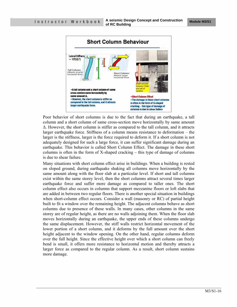
I n s t r u c t o r W o r k b o o k A seismic Design Concept and Construction of RC Building
Module M3/S1
M3/S1-16
Poor behavior of short columns is due to the fact that during an earthquake, a tall column and a short column of same cross-section move horizontally by same amount ∆. However, the short column is stiffer as compared to the tall column, and it attracts larger earthquake force. Stiffness of a column means resistance to deformation – the larger is the stiffness, larger is the force required to deform it. If a short column is not adequately designed for such a large force, it can suffer significant damage during an earthquake. This behavior is called Short Column Effect. The damage in these short columns is often in the form of X-shaped cracking – this type of damage of columns is due to shear failure. Many situations with short column effect arise in buildings. When a building is rested on sloped ground, during earthquake shaking all columns move horizontally by the same amount along with the floor slab at a particular level. If short and tall columns exist within the same storey level, then the short columns attract several times larger earthquake force and suffer more damage as compared to taller ones. The short column effect also occurs in columns that support mezzanine floors or loft slabs that are added in between two regular floors. There is another special situation in buildings when short-column effect occurs. Consider a wall (masonry or RC) of partial height built to fit a window over the remaining height. The adjacent columns behave as short columns due to presence of these walls. In many cases, other columns in the same storey are of regular height, as there are no walls adjoining them. When the floor slab moves horizontally during an earthquake, the upper ends of these columns undergo the same displacement. However, the stiff walls restrict horizontal movement of the lower portion of a short column, and it deforms by the full amount over the short height adjacent to the window opening. On the other hand, regular columns deform over the full height. Since the effective height over which a short column can freely bend is small, it offers more resistance to horizontal motion and thereby attracts a larger force as compared to the regular column. As a result, short column sustains more damage.
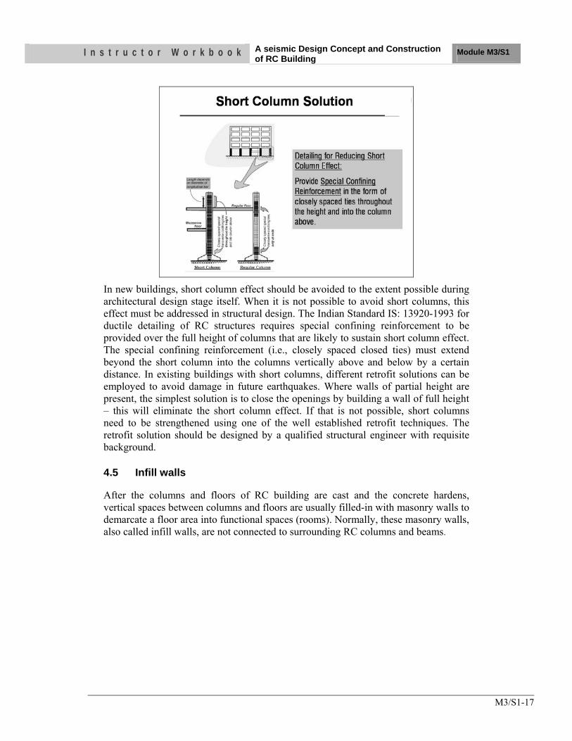
I n s t r u c t o r W o r k b o o k A seismic Design Concept and Construction of RC Building
Module M3/S1
M3/S1-17
In new buildings, short column effect should be avoided to the extent possible during architectural design stage itself. When it is not possible to avoid short columns, this effect must be addressed in structural design. The Indian Standard IS: 13920-1993 for ductile detailing of RC structures requires special confining reinforcement to be provided over the full height of columns that are likely to sustain short column effect. The special confining reinforcement (i.e., closely spaced closed ties) must extend beyond the short column into the columns vertically above and below by a certain distance. In existing buildings with short columns, different retrofit solutions can be employed to avoid damage in future earthquakes. Where walls of partial height are present, the simplest solution is to close the openings by building a wall of full height – this will eliminate the short column effect. If that is not possible, short columns need to be strengthened using one of the well established retrofit techniques. The retrofit solution should be designed by a qualified structural engineer with requisite background.
4.5 Infill walls
After the columns and floors of RC building are cast and the concrete hardens, vertical spaces between columns and floors are usually filled-in with masonry walls to demarcate a floor area into functional spaces (rooms). Normally, these masonry walls, also called infill walls, are not connected to surrounding RC columns and beams.
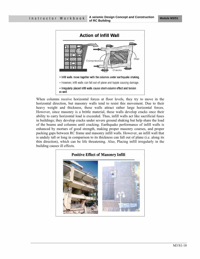
I n s t r u c t o r W o r k b o o k A seismic Design Concept and Construction of RC Building
Module M3/S1
M3/S1-18
When columns receive horizontal forces at floor levels, they try to move in the horizontal direction, but masonry walls tend to resist this movement. Due to their heavy weight and thickness, these walls attract rather large horizontal forces. However, since masonry is a brittle material, these walls develop cracks once their ability to carry horizontal load is exceeded. Thus, infill walls act like sacrificial fuses in buildings; they develop cracks under severe ground shaking but help share the load of the beams and columns until cracking. Earthquake performance of infill walls is enhanced by mortars of good strength, making proper masonry courses, and proper packing gaps between RC frame and masonry infill walls. However, an infill wall that is unduly tall or long in comparison to its thickness can fall out of plane (i.e. along its thin direction), which can be life threatening. Also, Placing infill irregularly in the building causes ill effects.
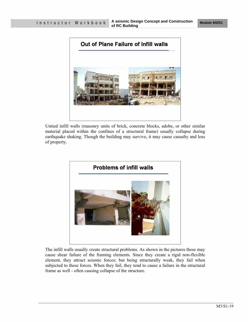
I n s t r u c t o r W o r k b o o k A seismic Design Concept and Construction of RC Building
Module M3/S1
M3/S1-19
Untied infill walls (masonry units of brick, concrete blocks, adobe, or other similar material placed within the confines of a structural frame) usually collapse during earthquake shaking. Though the building may survive, it may cause casualty and loss of property.
The infill walls usually create structural problems. As shown in the pictures these may cause shear failure of the framing elements. Since they create a rigid non-flexible element, they attract seismic forces; but being structurally weak, they fail when subjected to these forces. When they fail, they tend to cause a failure in the structural frame as well - often causing collapse of the structure.
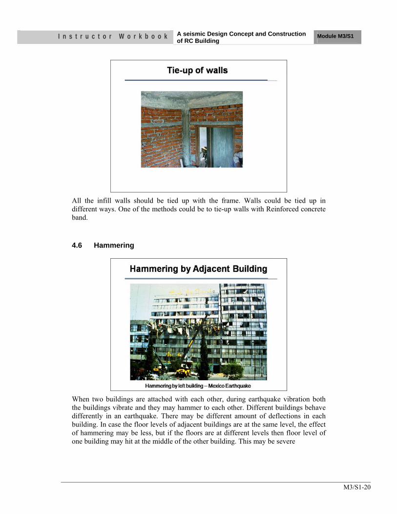
I n s t r u c t o r W o r k b o o k A seismic Design Concept and Construction of RC Building
Module M3/S1
M3/S1-20
All the infill walls should be tied up with the frame. Walls could be tied up in different ways. One of the methods could be to tie-up walls with Reinforced concrete band.
4.6 Hammering
When two buildings are attached with each other, during earthquake vibration both the buildings vibrate and they may hammer to each other. Different buildings behave differently in an earthquake. There may be different amount of deflections in each building. In case the floor levels of adjacent buildings are at the same level, the effect of hammering may be less, but if the floors are at different levels then floor level of one building may hit at the middle of the other building. This may be severe
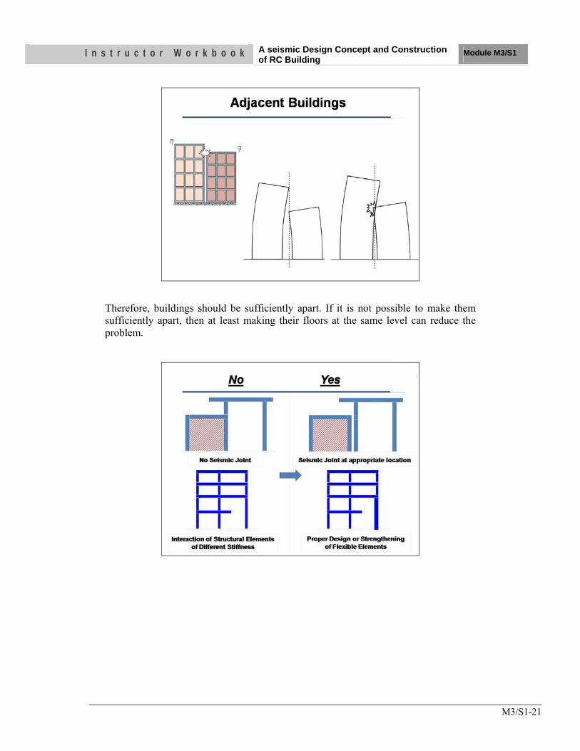
I n s t r u c t o r W o r k b o o k A seismic Design Concept and Construction of RC Building
Module M3/S1
M3/S1-21
Therefore, buildings should be sufficiently apart. If it is not possible to make them sufficiently apart, then at least making their floors at the same level can reduce the problem.
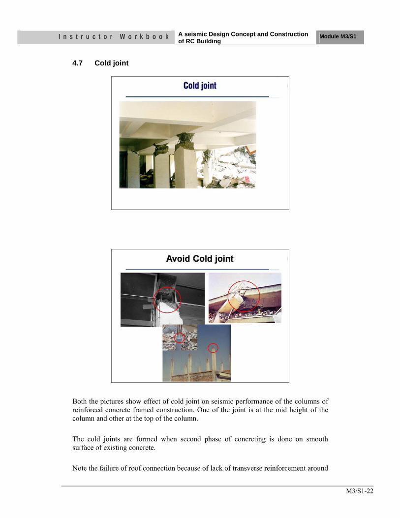
I n s t r u c t o r W o r k b o o k A seismic Design Concept and Construction of RC Building
Module M3/S1
M3/S1-22
4.7 Cold joint
Both the pictures show effect of cold joint on seismic performance of the columns of reinforced concrete framed construction. One of the joint is at the mid height of the column and other at the top of the column. The cold joints are formed when second phase of concreting is done on smooth surface of existing concrete. Note the failure of roof connection because of lack of transverse reinforcement around
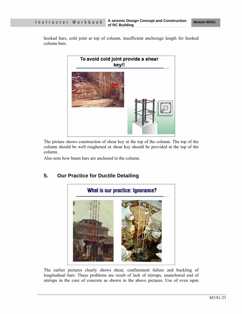
I n s t r u c t o r W o r k b o o k A seismic Design Concept and Construction of RC Building
Module M3/S1
M3/S1-23
hooked bars, cold joint at top of column, insufficient anchorage length for hooked column bars.
The picture shows construction of shear key at the top of the column. The top of the column should be well roughened or shear key should be provided at the top of the column. Also note how beam bars are anchored in the column.
5. Our Practice for Ductile Detailing
The earlier pictures clearly shows shear, confinement failure and buckling of longitudinal bars. These problems are result of lack of stirrups, unanchored end of stirrups in the core of concrete as shown in the above pictures. Use of even open
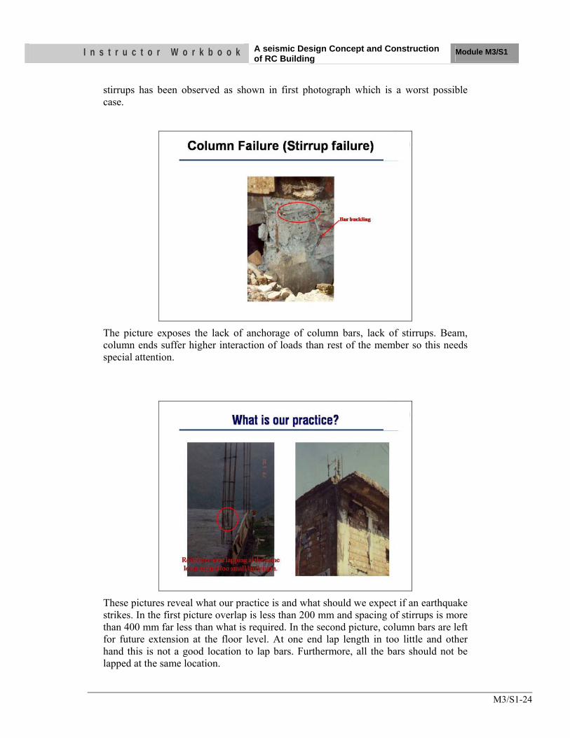
I n s t r u c t o r W o r k b o o k A seismic Design Concept and Construction of RC Building
Module M3/S1
M3/S1-24
stirrups has been observed as shown in first photograph which is a worst possible case.
The picture exposes the lack of anchorage of column bars, lack of stirrups. Beam, column ends suffer higher interaction of loads than rest of the member so this needs special attention.
These pictures reveal what our practice is and what should we expect if an earthquake strikes. In the first picture overlap is less than 200 mm and spacing of stirrups is more than 400 mm far less than what is required. In the second picture, column bars are left for future extension at the floor level. At one end lap length in too little and other hand this is not a good location to lap bars. Furthermore, all the bars should not be lapped at the same location.
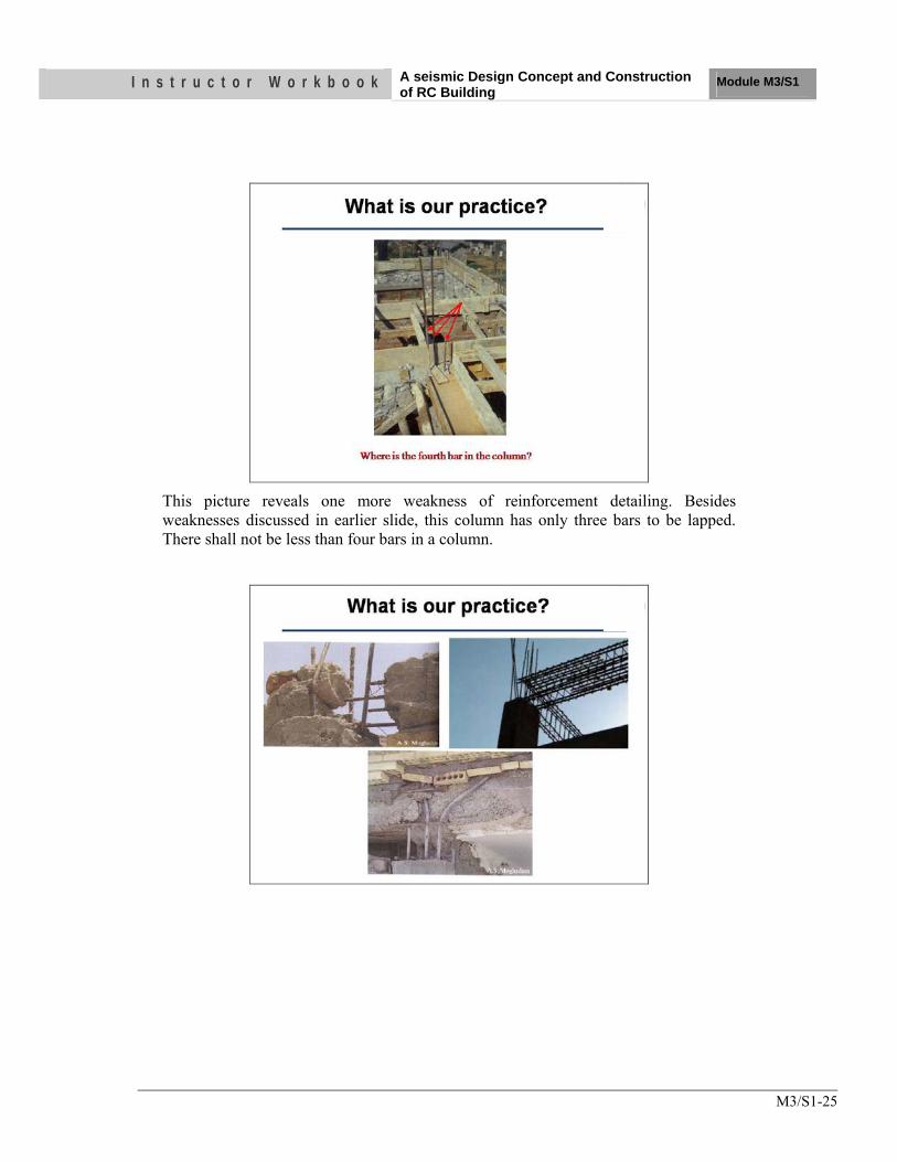
I n s t r u c t o r W o r k b o o k A seismic Design Concept and Construction of RC Building
Module M3/S1
M3/S1-25
This picture reveals one more weakness of reinforcement detailing. Besides weaknesses discussed in earlier slide, this column has only three bars to be lapped. There shall not be less than four bars in a column.
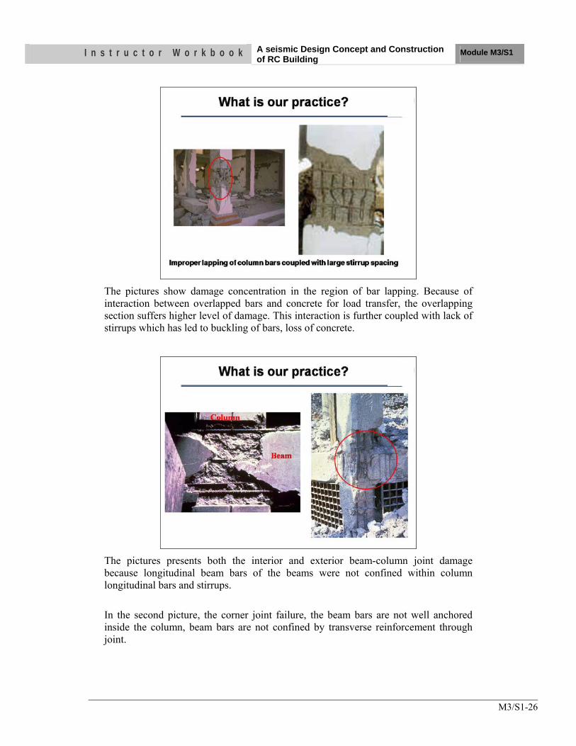
I n s t r u c t o r W o r k b o o k A seismic Design Concept and Construction of RC Building
Module M3/S1
M3/S1-26
The pictures show damage concentration in the region of bar lapping. Because of interaction between overlapped bars and concrete for load transfer, the overlapping section suffers higher level of damage. This interaction is further coupled with lack of stirrups which has led to buckling of bars, loss of concrete.
The pictures presents both the interior and exterior beam-column joint damage because longitudinal beam bars of the beams were not confined within column longitudinal bars and stirrups. In the second picture, the corner joint failure, the beam bars are not well anchored inside the column, beam bars are not confined by transverse reinforcement through joint.
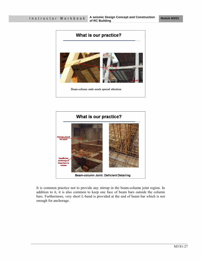
I n s t r u c t o r W o r k b o o k A seismic Design Concept and Construction of RC Building
Module M3/S1
M3/S1-27
It is common practice not to provide any stirrup in the beam-column joint region. In addition to it, it is also common to keep one face of beam bars outside the column bars. Furthermore, very short L-bend is provided at the end of beam bar which is not enough for anchorage.
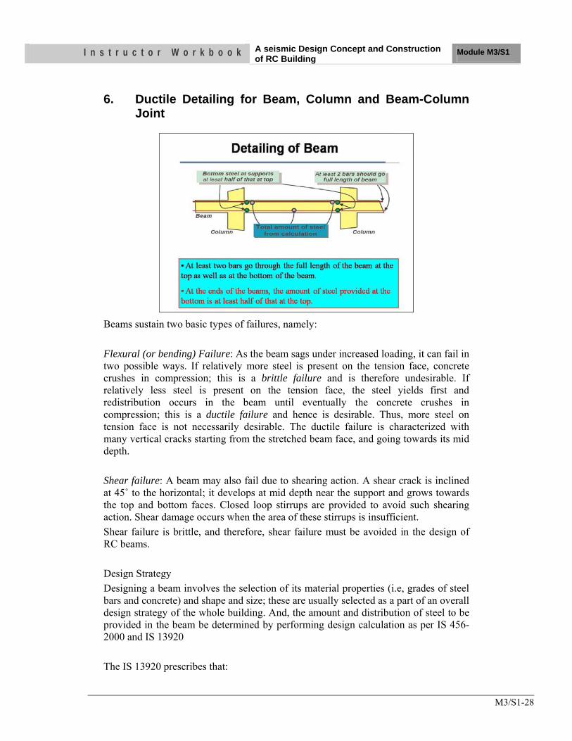
I n s t r u c t o r W o r k b o o k A seismic Design Concept and Construction of RC Building
Module M3/S1
M3/S1-28
6. Ductile Detailing for Beam, Column and Beam-Column Joint
Beams sustain two basic types of failures, namely: Flexural (or bending) Failure: As the beam sags under increased loading, it can fail in two possible ways. If relatively more steel is present on the tension face, concrete crushes in compression; this is a brittle failure and is therefore undesirable. If relatively less steel is present on the tension face, the steel yields first and redistribution occurs in the beam until eventually the concrete crushes in compression; this is a ductile failure and hence is desirable. Thus, more steel on tension face is not necessarily desirable. The ductile failure is characterized with many vertical cracks starting from the stretched beam face, and going towards its mid depth. Shear failure: A beam may also fail due to shearing action. A shear crack is inclined at 45˚ to the horizontal; it develops at mid depth near the support and grows towards the top and bottom faces. Closed loop stirrups are provided to avoid such shearing action. Shear damage occurs when the area of these stirrups is insufficient. Shear failure is brittle, and therefore, shear failure must be avoided in the design of RC beams. Design Strategy Designing a beam involves the selection of its material properties (i.e, grades of steel bars and concrete) and shape and size; these are usually selected as a part of an overall design strategy of the whole building. And, the amount and distribution of steel to be provided in the beam be determined by performing design calculation as per IS 456-2000 and IS 13920 The IS 13920 prescribes that:
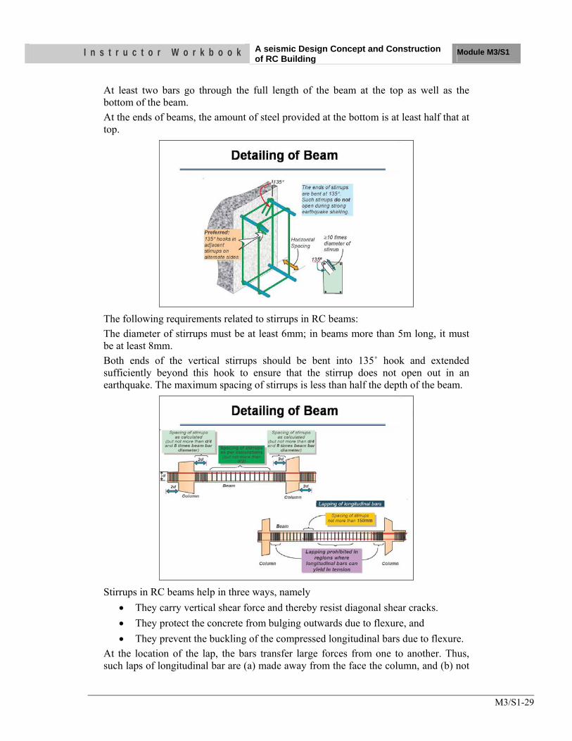
I n s t r u c t o r W o r k b o o k A seismic Design Concept and Construction of RC Building
Module M3/S1
M3/S1-29
At least two bars go through the full length of the beam at the top as well as the bottom of the beam. At the ends of beams, the amount of steel provided at the bottom is at least half that at top.
The following requirements related to stirrups in RC beams: The diameter of stirrups must be at least 6mm; in beams more than 5m long, it must be at least 8mm. Both ends of the vertical stirrups should be bent into 135˚ hook and extended sufficiently beyond this hook to ensure that the stirrup does not open out in an earthquake. The maximum spacing of stirrups is less than half the depth of the beam.
Stirrups in RC beams help in three ways, namely
• They carry vertical shear force and thereby resist diagonal shear cracks. • They protect the concrete from bulging outwards due to flexure, and • They prevent the buckling of the compressed longitudinal bars due to flexure.
At the location of the lap, the bars transfer large forces from one to another. Thus, such laps of longitudinal bar are (a) made away from the face the column, and (b) not
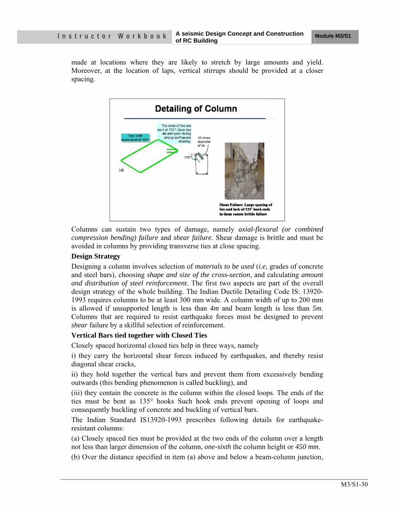
I n s t r u c t o r W o r k b o o k A seismic Design Concept and Construction of RC Building
Module M3/S1
M3/S1-30
made at locations where they are likely to stretch by large amounts and yield. Moreover, at the location of laps, vertical stirrups should be provided at a closer spacing.
Columns can sustain two types of damage, namely axial-flexural (or combined compression bending) failure and shear failure. Shear damage is brittle and must be avoided in columns by providing transverse ties at close spacing. Design Strategy Designing a column involves selection of materials to be used (i.e, grades of concrete and steel bars), choosing shape and size of the cross-section, and calculating amount and distribution of steel reinforcement. The first two aspects are part of the overall design strategy of the whole building. The Indian Ductile Detailing Code IS: 13920-1993 requires columns to be at least 300 mm wide. A column width of up to 200 mm is allowed if unsupported length is less than 4m and beam length is less than 5m. Columns that are required to resist earthquake forces must be designed to prevent shear failure by a skillful selection of reinforcement. Vertical Bars tied together with Closed Ties Closely spaced horizontal closed ties help in three ways, namely i) they carry the horizontal shear forces induced by earthquakes, and thereby resist diagonal shear cracks, ii) they hold together the vertical bars and prevent them from excessively bending outwards (this bending phenomenon is called buckling), and (iii) they contain the concrete in the column within the closed loops. The ends of the ties must be bent as 135° hooks Such hook ends prevent opening of loops and consequently buckling of concrete and buckling of vertical bars. The Indian Standard IS13920-1993 prescribes following details for earthquake-resistant columns: (a) Closely spaced ties must be provided at the two ends of the column over a length not less than larger dimension of the column, one-sixth the column height or 450 mm. (b) Over the distance specified in item (a) above and below a beam-column junction,
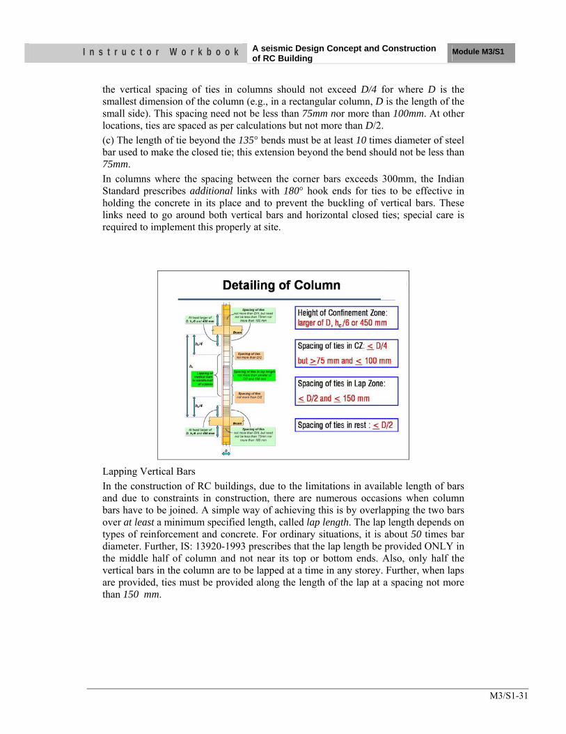
I n s t r u c t o r W o r k b o o k A seismic Design Concept and Construction of RC Building
Module M3/S1
M3/S1-31
the vertical spacing of ties in columns should not exceed D/4 for where D is the smallest dimension of the column (e.g., in a rectangular column, D is the length of the small side). This spacing need not be less than 75mm nor more than 100mm. At other locations, ties are spaced as per calculations but not more than D/2. (c) The length of tie beyond the 135° bends must be at least 10 times diameter of steel bar used to make the closed tie; this extension beyond the bend should not be less than 75mm. In columns where the spacing between the corner bars exceeds 300mm, the Indian Standard prescribes additional links with 180° hook ends for ties to be effective in holding the concrete in its place and to prevent the buckling of vertical bars. These links need to go around both vertical bars and horizontal closed ties; special care is required to implement this properly at site.
Lapping Vertical Bars In the construction of RC buildings, due to the limitations in available length of bars and due to constraints in construction, there are numerous occasions when column bars have to be joined. A simple way of achieving this is by overlapping the two bars over at least a minimum specified length, called lap length. The lap length depends on types of reinforcement and concrete. For ordinary situations, it is about 50 times bar diameter. Further, IS: 13920-1993 prescribes that the lap length be provided ONLY in the middle half of column and not near its top or bottom ends. Also, only half the vertical bars in the column are to be lapped at a time in any storey. Further, when laps are provided, ties must be provided along the length of the lap at a spacing not more than 150 mm.
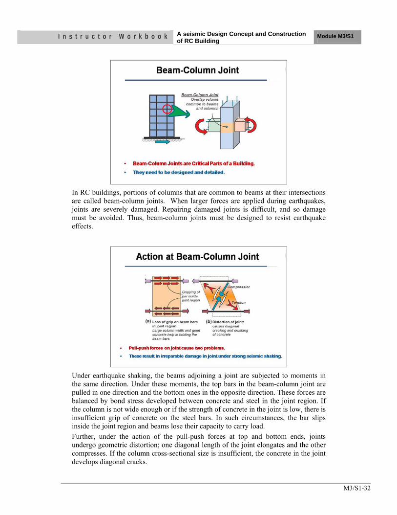
I n s t r u c t o r W o r k b o o k A seismic Design Concept and Construction of RC Building
Module M3/S1
M3/S1-32
In RC buildings, portions of columns that are common to beams at their intersections are called beam-column joints. When larger forces are applied during earthquakes, joints are severely damaged. Repairing damaged joints is difficult, and so damage must be avoided. Thus, beam-column joints must be designed to resist earthquake effects.
Under earthquake shaking, the beams adjoining a joint are subjected to moments in the same direction. Under these moments, the top bars in the beam-column joint are pulled in one direction and the bottom ones in the opposite direction. These forces are balanced by bond stress developed between concrete and steel in the joint region. If the column is not wide enough or if the strength of concrete in the joint is low, there is insufficient grip of concrete on the steel bars. In such circumstances, the bar slips inside the joint region and beams lose their capacity to carry load. Further, under the action of the pull-push forces at top and bottom ends, joints undergo geometric distortion; one diagonal length of the joint elongates and the other compresses. If the column cross-sectional size is insufficient, the concrete in the joint develops diagonal cracks.
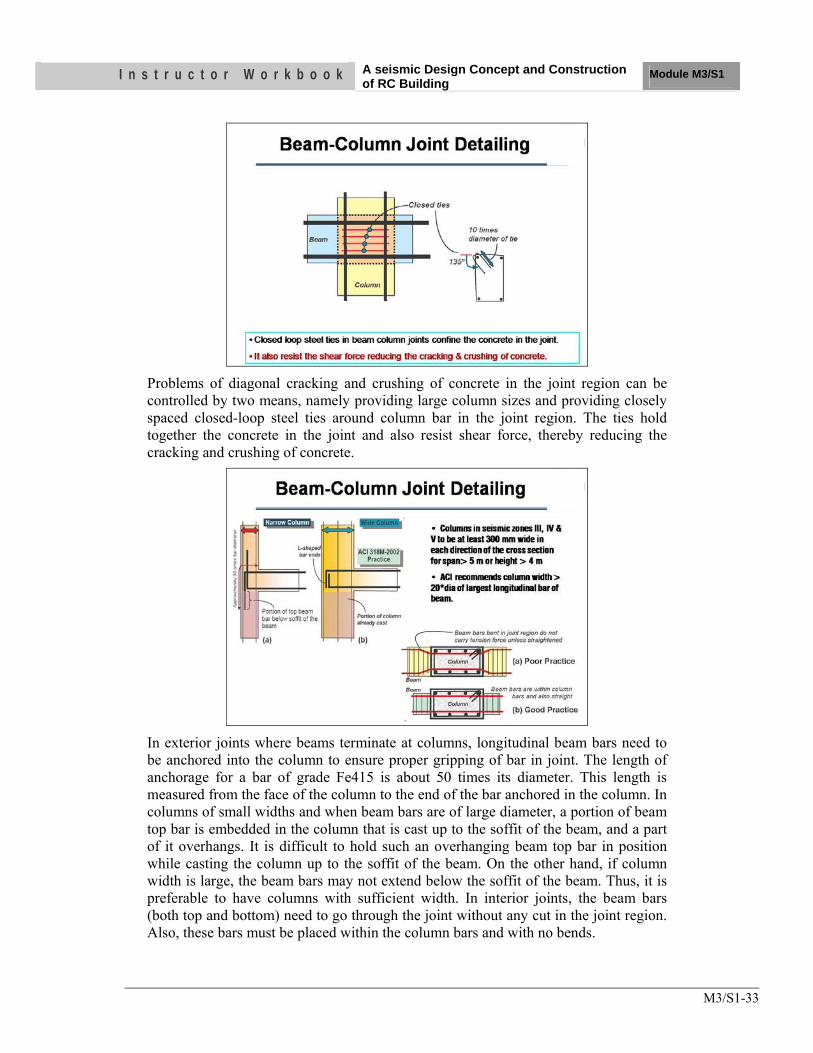
I n s t r u c t o r W o r k b o o k A seismic Design Concept and Construction of RC Building
Module M3/S1
M3/S1-33
Problems of diagonal cracking and crushing of concrete in the joint region can be controlled by two means, namely providing large column sizes and providing closely spaced closed-loop steel ties around column bar in the joint region. The ties hold together the concrete in the joint and also resist shear force, thereby reducing the cracking and crushing of concrete.
In exterior joints where beams terminate at columns, longitudinal beam bars need to be anchored into the column to ensure proper gripping of bar in joint. The length of anchorage for a bar of grade Fe415 is about 50 times its diameter. This length is measured from the face of the column to the end of the bar anchored in the column. In columns of small widths and when beam bars are of large diameter, a portion of beam top bar is embedded in the column that is cast up to the soffit of the beam, and a part of it overhangs. It is difficult to hold such an overhanging beam top bar in position while casting the column up to the soffit of the beam. On the other hand, if column width is large, the beam bars may not extend below the soffit of the beam. Thus, it is preferable to have columns with sufficient width. In interior joints, the beam bars (both top and bottom) need to go through the joint without any cut in the joint region. Also, these bars must be placed within the column bars and with no bends.
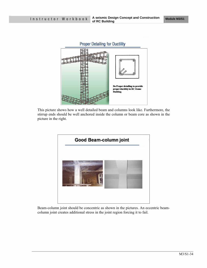
I n s t r u c t o r W o r k b o o k A seismic Design Concept and Construction of RC Building
Module M3/S1
M3/S1-34
This picture shows how a well detailed beam and columns look like. Furthermore, the stirrup ends should be well anchored inside the column or beam core as shown in the picture in the right.
Beam-column joint should be concentric as shown in the pictures. An eccentric beam-column joint creates additional stress in the joint region forcing it to fail.
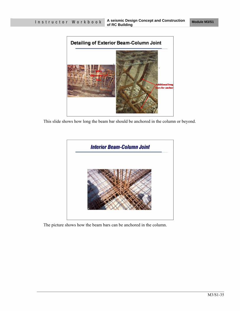
I n s t r u c t o r W o r k b o o k A seismic Design Concept and Construction of RC Building
Module M3/S1
M3/S1-35
This slide shows how long the beam bar should be anchored in the column or beyond.
The picture shows how the beam bars can be anchored in the column.
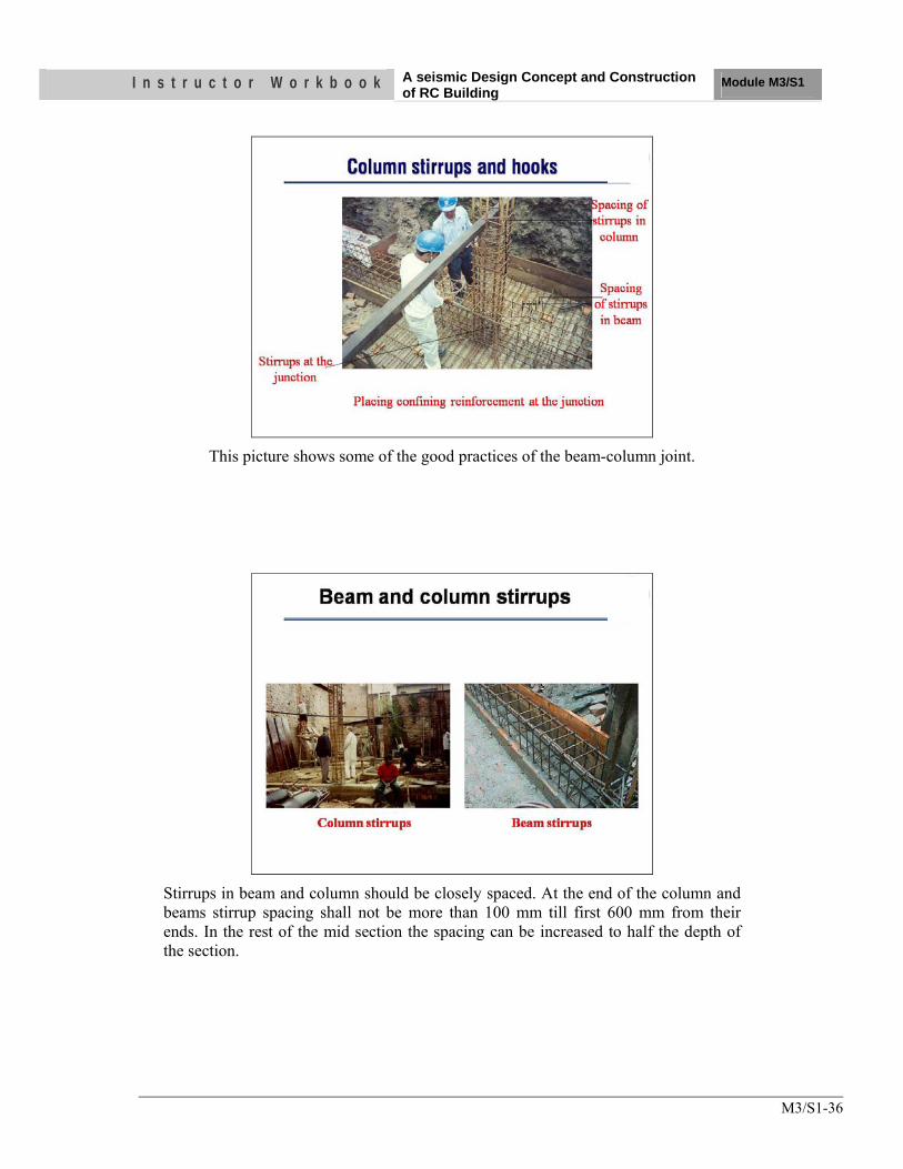
I n s t r u c t o r W o r k b o o k A seismic Design Concept and Construction of RC Building
Module M3/S1
M3/S1-36
This picture shows some of the good practices of the beam-column joint.
Stirrups in beam and column should be closely spaced. At the end of the column and beams stirrup spacing shall not be more than 100 mm till first 600 mm from their ends. In the rest of the mid section the spacing can be increased to half the depth of the section.
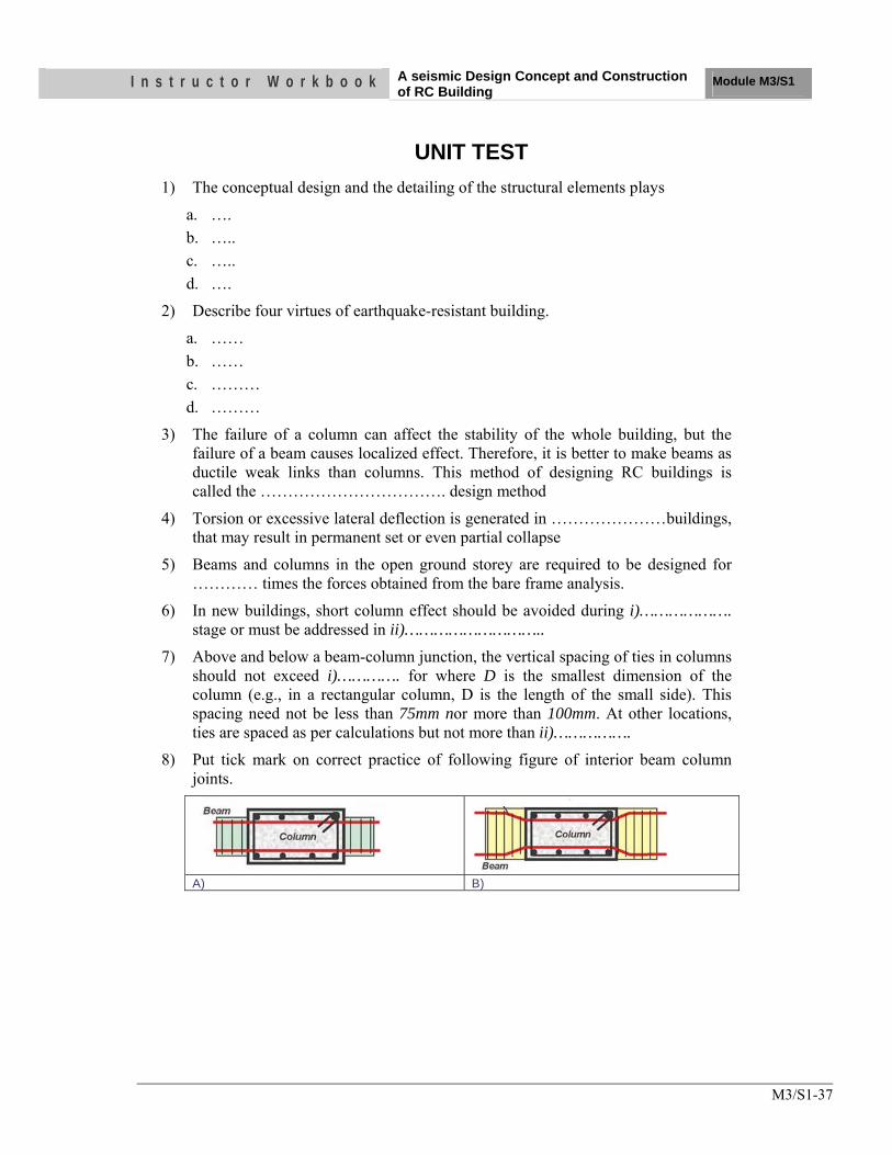
I n s t r u c t o r W o r k b o o k A seismic Design Concept and Construction of RC Building
Module M3/S1
M3/S1-37
UNIT TEST 1) The conceptual design and the detailing of the structural elements plays
a. …. b. ….. c. ….. d. ….
2) Describe four virtues of earthquake-resistant building.
a. …… b. …… c. ……… d. ………
3) The failure of a column can affect the stability of the whole building, but the failure of a beam causes localized effect. Therefore, it is better to make beams as ductile weak links than columns. This method of designing RC buildings is called the ……………………………. design method
4) Torsion or excessive lateral deflection is generated in …………………buildings, that may result in permanent set or even partial collapse
5) Beams and columns in the open ground storey are required to be designed for ………… times the forces obtained from the bare frame analysis.
6) In new buildings, short column effect should be avoided during i)………………. stage or must be addressed in ii)………………………..
7) Above and below a beam-column junction, the vertical spacing of ties in columns should not exceed i)…………. for where D is the smallest dimension of the column (e.g., in a rectangular column, D is the length of the small side). This spacing need not be less than 75mm nor more than 100mm. At other locations, ties are spaced as per calculations but not more than ii)…………….
8) Put tick mark on correct practice of following figure of interior beam column joints.
A) B)
OBJECTIVES As a result of this session, you should be able to:
•• UUnnddeerrssttaanndd tthhee mmaajjoorr wweeaakknneesssseess ooff oouurr bbuuiillddiinngg ttyyppeess
• UUnnddeerrssttaanndd tthhee rreemmeeddiiaall mmeeaassuurreess ttoo iimmpprroovvee tthhee rreessppoonnssee ooff tthhee bbuuiillddiinngg iinn llaarrggee eeaarrtthhqquuaakkee
Instructor Workbook Module M3/S2
A Seismic Design Concept and Construction of Masonry Building
I n s t r u c t o r W o r k b o o k A Seismic Design Concept and Construction of Masonry Building Module M3/S2
ii
CONTENTS
1. Introduction ................................................................................................1 2. Earthquake Behaviour of Masonry Walls ...............................................1 3. Major Deficiencies of Masonry Building Types ......................................2
3.1 Asymmetric Configuration .................................................................2
3.2 Lack of Strength and Stiffness ............................................................3
3.3 Lack of Cross Walls ............................................................................4
3.4 Lack of Integrity between Walls, Roof and Floor ..............................4
3.5 Absence of Vertical bar, Horizontal Bands at Plinth, Sill, Lintel and Floor/Roof Level .................................................................................6
3.6 Construction Deficiency .....................................................................7
4. Stone Masonry ............................................................................................8
4.1 Earthquake Resistant Features on stone Masonry ..............................9
I n s t r u c t o r W o r k b o o k A Seismic Design Concept and Construction of Masonry Building Module M3/S2
M3/S2-1
1. Introduction
In non-urban areas most buildings are made of load bearing wall masonry. In the plains, masonry is generally made of burnt clay bricks and cement mortar. However, in hilly areas, stone masonry with mud mortar is more prevalent; but, in recent times, it is being replaced with cement mortar. Masonry can carry loads that cause compression, but can hardly take load that causes tension.
Masonry buildings are brittle structures and one of the most vulnerable of the entire building elements under strong earthquake shaking. This is corroborated by the large number of human fatalities in such constructions during the past earthquakes in world. Thus, it is very important to improve the seismic behavior of masonry buildings. A number of earthquake-resistant features can be introduced to achieve this objective.
Ground vibrations during earthquakes cause inertia forces at locations of mass in the building. These forces travel through the roof and walls to the foundation. The main emphasis is on ensuring that these forces reach the ground without causing major damage or collapse. Of the three components of a masonry building (roof, wall and foundation), the walls are most vulnerable to damage caused by horizontal forces due to earthquake.
2. Earthquake Behaviour of Masonry Walls
Brick masonry buildings have large mass and hence attract large horizontal forces during earthquake shaking. They develop numerous cracks under both compressive and tensile forces caused by earthquake shaking. The aim of earthquake resistant masonry building construction is to ensure that these effects are sustained without major damage or collapse. Appropriate choice of structural configuration can help achieve this. The structural configuration of masonry buildings includes aspects like (a) overall shape and size of the building, and (b) distribution of mass and (horizontal) lateral load resisting elements across the building. Large, tall, long and unsymmetrical buildings perform poorly during earthquakes. A strategy used in making them earthquake resistant is developing a good box action between all the elements of the building, i.e., between roof, walls and foundation. Loosely connected roof or unduly slender walls are threats to good seismic behavior. For example, a horizontal band introduced at the lintel level ties the walls together and helps to make them behave as a single unit.
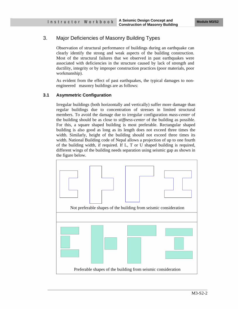
I n s t r u c t o r W o r k b o o k A Seismic Design Concept and Construction of Masonry Building Module M3/S2
M3-S2-2
3. Major Deficiencies of Masonry Building Types
Observation of structural performance of buildings during an earthquake can clearly identify the strong and weak aspects of the building construction. Most of the structural failures that we observed in past earthquakes were associated with deficiencies in the structure caused by lack of strength and ductility, integrity or by improper construction practices (poor materials, poor workmanship).
As evident from the effect of past earthquakes, the typical damages to non-engineered masonry buildings are as follows:
3.1 Asymmetric Configuration
Irregular buildings (both horizontally and vertically) suffer more damage than regular buildings due to concentration of stresses in limited structural members. To avoid the damage due to irregular configuration mass-center of the building should be as close to stiffness-center of the building as possible. For this, a square shaped building is most preferable. Rectangular shaped building is also good as long as its length does not exceed three times the width. Similarly, height of the building should not exceed three times its width. National Building code of Nepal allows a projection of up to one fourth of the building width, if required. If L, T or U shaped building is required, different wings of the building needs separation using seismic gap as shown in the figure below.
Not preferable shapes of the building from seismic consideration
Preferable shapes of the building from seismic consideration
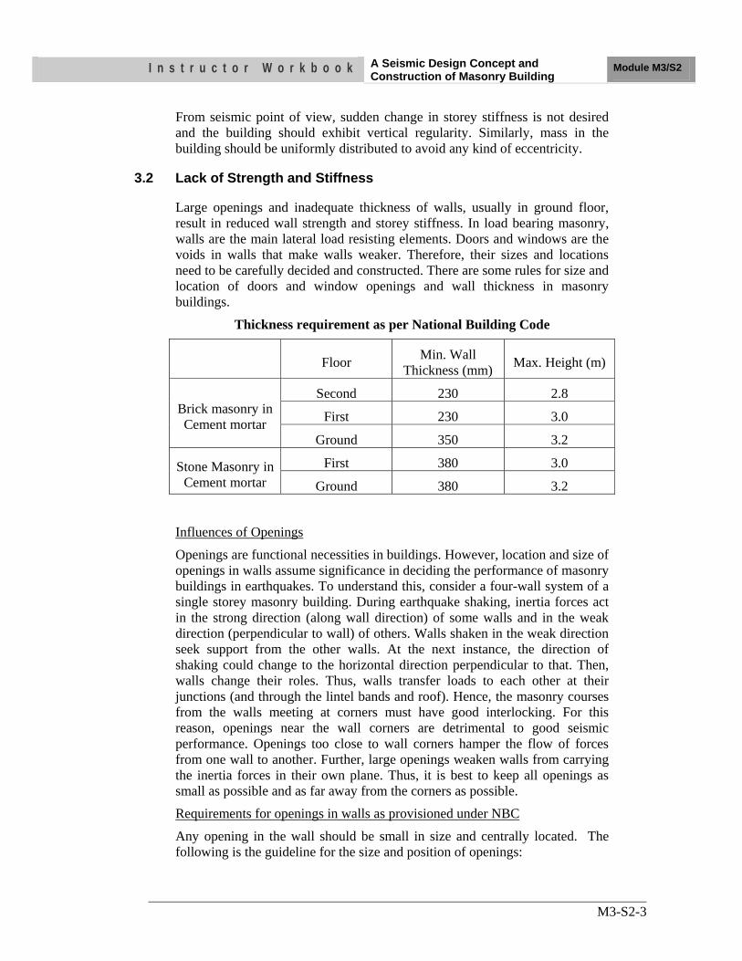
I n s t r u c t o r W o r k b o o k A Seismic Design Concept and Construction of Masonry Building Module M3/S2
M3-S2-3
From seismic point of view, sudden change in storey stiffness is not desired and the building should exhibit vertical regularity. Similarly, mass in the building should be uniformly distributed to avoid any kind of eccentricity.
3.2 Lack of Strength and Stiffness
Large openings and inadequate thickness of walls, usually in ground floor, result in reduced wall strength and storey stiffness. In load bearing masonry, walls are the main lateral load resisting elements. Doors and windows are the voids in walls that make walls weaker. Therefore, their sizes and locations need to be carefully decided and constructed. There are some rules for size and location of doors and window openings and wall thickness in masonry buildings.
Thickness requirement as per National Building Code
Floor Min. Wall Thickness (mm) Max. Height (m)
Brick masonry in Cement mortar
Second 230 2.8
First 230 3.0
Ground 350 3.2
Stone Masonry in Cement mortar
First 380 3.0
Ground 380 3.2
Influences of Openings
Openings are functional necessities in buildings. However, location and size of openings in walls assume significance in deciding the performance of masonry buildings in earthquakes. To understand this, consider a four-wall system of a single storey masonry building. During earthquake shaking, inertia forces act in the strong direction (along wall direction) of some walls and in the weak direction (perpendicular to wall) of others. Walls shaken in the weak direction seek support from the other walls. At the next instance, the direction of shaking could change to the horizontal direction perpendicular to that. Then, walls change their roles. Thus, walls transfer loads to each other at their junctions (and through the lintel bands and roof). Hence, the masonry courses from the walls meeting at corners must have good interlocking. For this reason, openings near the wall corners are detrimental to good seismic performance. Openings too close to wall corners hamper the flow of forces from one wall to another. Further, large openings weaken walls from carrying the inertia forces in their own plane. Thus, it is best to keep all openings as small as possible and as far away from the corners as possible.
Requirements for openings in walls as provisioned under NBC
Any opening in the wall should be small in size and centrally located. The following is the guideline for the size and position of openings:
I n s t r u c t o r W o r k b o o k A Seismic Design Concept and Construction of Masonry Building Module M3/S2
M3-S2-4
i) Openings are to be located away from inside corners by a clear distance equal to at least 1/4 of the height of the opening, but not less than 600 mm.
ii) The total length of openings in a wall is not to exceed 50 % of the length of the wall between consecutive cross-walls in single-storey construction, 42 % in two-storey construction, and 33 % in three-storey buildings.
iii) The horizontal distance (pier width) between two openings is to be not less than one half of the height of the shorter opening, but not less than 600 mm.
iv) The vertical distance from one opening to another opening directly above it shall not be less than 600 mm, nor less than one half the width of the smaller opening
v) When an opening does not comply with requirements (i) to (iv), it shall be boxed in reinforced jambs through the masonry.
vi) If the vertical opening of the wall is more than 50 % of the wall height, vertical bars shall be provided in the jambs.
3.3 Lack of Cross Walls
Many masonry buildings use to fail because of long unsupported walls. For a masonry building to be earthquake resistant, the free length of walls (length between cross walls) and height of the wall should not be unnecessarily long or high. The maximum length of unsupported wall shall not be more than 12 times its thickness. If it is necessary to make more than 12 times, buttress walls shall be provided to limit the unsupported length less than 12 times its thickness. The height to thickness ratio of the walls should be limited to 1:12 for brick or block masonry and 1:8 for stone masonry. These buttresses should be constructed simultaneously with the main walls and well integrated.
These buttresses are used to provide lateral support to the masonry wall in the horizontal direction.
3.4 Lack of Integrity between Walls, Roof and Floor
Non-existent or improper connections between walls, roof and floor is another major deficiency of masonry buildings. As envisaged by past earthquakes,
I n s t r u c t o r W o r k b o o k A Seismic Design Concept and Construction of Masonry Building Module M3/S2
M3-S2-5
most of the non-engineered masonry buildings collapsed due to lack of bonding and anchorage between wall to wall, wall to roof/floor and between elements of roof/floor. Such conditions arise mainly due to:
i) The practice of providing toothed joint between two consecutive walls.
ii) Roof/Floor simply rests on wall without any anchorage
iii) Elements of roof/slab are not tied properly
iv) Improper bonding between masonry units leading to vertical joint in the wall.
Integrity of the masonry units can be improved by enduring a proper connection between these elements so that the building acts as a single unit enhancing the lateral load resisting capacity of the building.
Some examples of improving the integrity of the building are illustrated below.
Step Joint at Corners
The weakness due to toothed joints can be improved easily by providing stepped joints whenever necessary. Steps are easy to construct and when another wall is to be joined, mortar can be placed at all necessary surfaces. It allows escaping the joint at the same vertical line. This option does not require additional money, but improves the joint strength significantly.
L Shaped Stitch
For ensuring earthquake safety, providing stepped joints alone is not sufficient. Some extra strengthening elements called stitches should be provided. Stitches are L or T shaped elements which joins two orthogonal walls properly. The stitches work as nails in wooden box where planks are nailed together to make a box. RCC stitches are suitable for masonry buildings with cement sand mortar and timber or bamboo stitches are suitable for masonry buildings with mud mortar. However, RCC stitch can also be provided in the building with mud mortar.
I n s t r u c t o r W o r k b o o k A Seismic Design Concept and Construction of Masonry Building Module M3/S2
M3-S2-6
T Shaped Stitch
Anchorage of Roof to Wall
Floor/roof slab or truss should have a sufficient bearing to wall and tied properly to prevent relative displacement between the wall and roof element at joint ensuring stability of the structure. Use of metal ties is common as an anchoring element. Many buildings in past earthquakes have collapsed due to inadequate connection between roof/floor and wall system.
Door/Window openings attached to wall junctions also increases weakness of the building. Openings shall be provided either at a distance such that
P1 > 0.25h1
P2 > 0.25h2
P3 > 0.50h2 or at least 600 mm from the wall junction.
3.5 Absence of Vertical bar, Horizontal Bands at Plinth, Sill, Lintel and Floor/Roof Level
Masonry is a brittle material and the flexural strength of masonry wall is almost negligible. Therefore, during earthquake shaking, masonry walls get damaged due to out of plane and in-plane bending. To prevent such damage, masonry wall is tied by providing horizontal bands at plinth, sill, lintel and roof/floor level and vertical bars at wall junctions and at jambs of door/window openings. The bandages are designed for out-of-plane bending
I n s t r u c t o r W o r k b o o k A Seismic Design Concept and Construction of Masonry Building Module M3/S2
M3-S2-7
and vertical reinforcement bars are designed for in-plane bending. The band may be of RCC, timber, bamboo depending upon the material available and type of the building construction. For a building with cement mortar, RC band is preferable. A timber band could be used for building with mud mortar. However, RCC band can also be used in the buildings with mud mortar.
The problem with two-side sloped roof buildings is failure of gable walls. Gable wall in a building is at the highest level and the displacement of wall at the top is more than that at the bottom. Usually gable walls are untied at the top. The height becomes more in gable walls which enable them fall more easily. To mitigate the problem, bandages similar to other bands should be provided at bottom and the slope of the gable wall as shown in the figure below. Details of the gable wall band are similar to the bands at sill level and the lintel level.
Horizontal bands and vertical bars act as earthquake resistant elements in masonry buildings
Use of gable band Gable wall is replaced by light weight sheet
3.6 Construction Deficiency
Buildings behave as they are actually constructed and not as they are designed or planned. No matter how well a building is planned and designed if they are poorly constructed, it performs poorly. Therefore, quality and workmanship during each stage of the construction play a vital role in making a building of
I n s t r u c t o r W o r k b o o k A Seismic Design Concept and Construction of Masonry Building Module M3/S2
M3-S2-8
good quality, strong and earthquake resistant. Besides good planning and design, quality control should also be given high attention during the construction. First factor to affect the quality of a building is the quality of its planning and designing. If a building is not properly planned and designed, the building could never attain good quality even if it is constructed with greater care and quality control. For a building to be an earthquake resistant, a good quality planning and design means to follow the basic rules such as appropriate site selection, good configuration and layout, appropriate size and detailing of different structural elements etc. Another factor affecting the quality of a building is quality of materials used in the construction. Inferior quality materials cannot make a good quality building. Therefore materials used in the construction should be of good quality as mentioned in the specifications. Next major factor to contribute in the quality of a building is quality of construction process and quality of workmanship. Each and every stage of the construction should be in accordance with the provisions and steps mentioned in the standard construction manuals and guidelines. Resources and time available are also the indirect factors to make a good quality building. Experiences show that prolonged project period due to resource constraints result in decreased quality of construction.
4. Stone Masonry
In a typical rural stone house, thick stone masonry walls (thickness ranges from 600 to 1200 mm) are built using rounded stones from riverbeds and mud mortar. These walls are constructed with stones placed in a random manner and hence do not have the usual layers (or courses) as seen in brick walls. These uncoursed walls have two vertical layers (called wythes) of large stones, which is filled in between with loose stone rubble and mud mortar. In many cases, these walls support heavy roofs (for example, timber roof with thick mud overlay).
These buildings are one of the most deficient building systems from earthquake-resistance point of view. The main deficiencies include excessive wall thickness, absence of any connection between the two wythes of the wall, and use of round stones (instead of shaped ones). Such buildings have shown very poor performance during past earthquakes. In the 1993 Killari (Maharashtra) earthquake alone, over 8,000 people died, most of them were buried under the rubble of traditional stone masonry dwellings. Likewise, a majority of over 13,800 deaths during 2001 Bhuj (Gujarat) earthquake is attributed to the collapse of this type of construction. The main patterns of earthquake damage include: (a) bulging/separation of walls in the horizontal direction into two distinct wythes (b) separation of walls at corners and T-junctions, (c) separation of poorly constructed roof from walls, and eventual collapse of roof, and (d) disintegration of walls and eventual collapse of the whole dwelling.
I n s t r u c t o r W o r k b o o k A Seismic Design Concept and Construction of Masonry Building Module M3/S2
M3-S2-9
4.1 Earthquake Resistant Features on stone Masonry
The earthquake-resistant design and construction features may raise the earthquake resistance of these buildings and reduce the loss of life. However, in spite of the seismic features these buildings may not become totally free from heavy damage and even collapse in case of a major earthquake. The contribution of the each of these features is difficult to quantify, but qualitatively these features have been observed to improve the performance of stone masonry dwellings during past earthquakes. These features include:
(a) Ensure proper wall construction: The wall thickness should not exceed 450mm. Round stone boulders should not be used in the construction! Instead, the stones should be shaped using chisels and hammers. Use of mud mortar should be avoided in higher seismic zones. Instead, cement-sand mortar should be 1:6 (or richer) and lime-sand mortar 1:3 (or richer) should be used.
(b) Ensure proper bond in masonry courses: The masonry walls should be built in construction lifts not exceeding 600mm. Through-stones (each extending over full thickness of wall) or a pair of overlapping bond-stones (each extending over at least ¾ th thickness of wall) must be used at every 600mm along the height and at a maximum spacing of 1.2m along the length.
(c) Provide horizontal reinforcing elements: The stone masonry dwellings must have horizontal bands. These bands can be constructed out of wood or reinforced concrete, and chosen based on economy. It is important to provide at least one band (either lintel band or roof band) in stone masonry construction.
(d) Control on overall dimensions and heights: The unsupported length of walls between cross-walls should be limited to 5m; for longer walls, cross supports raised from the ground level called buttresses should be provided at spacing not more than 4m. The height of each storey should not exceed 3.0 m. In general, stone masonry buildings should not be taller than 2 storeys when built in cement mortar, and 1 storey when built in lime or mud mortar. The wall should have a thickness of at least one-sixth its height.
Although construction practice of stone masonry of such type is deficient as regards to earthquake resistance, its extensive use is likely to continue due to tradition and its low cost. But, to protect human lives and property in future earthquakes, it is necessary to follow proper technique of stone masonry construction as described above.
I n s t r u c t o r W o r k b o o k A Seismic Design Concept and Construction of Masonry Building Module M3/S2
M3-S2-10
UNIT TEST
1) Describe major deficiencies of masonry buildings
…………………………………………………………………………………………………………………………………………………………………………………………………………………………………………………………………………………………………………………………………………………………………………………………………………………………………………
2) Sum of the width of openings in brick masonry for
Single storey:
Double storey:
Three storeys:
Distance of opening from corner:
3) The length of the stitch on either side should be at least ……………………. times the wall thickness but not less than ………. feet.
4) Horizontal band at sill, lintel and eve level should be designed for ……….bending.
5) For masonry buildings of more than two stories, minimum ….... nos of ….....mm dia longitudinal bars with ….…..mm lateral ties (shear reinforcement) is to be provided. Grade of concrete shall be at least of M15 (1:2:4).
6) Through stones should be provided at the horizontal interval of not more than … feet and vertical interval of not more than……….feet. The through stones should be provided in staggered fashion
OBJECTIVES As a result of this session, you should be able to:
•• DDiissccuussss iissssuueess oonn pprreelliimmiinnaarryy ssyysstteemm ddeessiiggnn ccoonnssiiddeerriinngg eeaarrtthhqquuaakkee eeffffeeccttss
• List two components of basic structural system
•• DDiissccuussss IIssssuueess oonn ooppttiimmiizziinngg aarrcchhiitteeccttuurraall//ssttrruuccttuurraall ccoonnffiigguurraattiioonnss
•• DDiissccuussss iinntteenntt,, eexxppeeccttaattiioonnss aanndd eexxppeecctteedd ppeerrffoorrmmaannccee ddeeffiinneedd bbyy ccooddeess
•• LLiisstt ffiivvee ccoommmmoonn sseennssee iissssuueess ttoo vveerriiffyy tthhee ddeessiiggnn
Instructor Workbook ModuleM3/S3
Earthquake Resistance Analysis and Design Procedures
I n s t r u c t o r W o r k b o o k Earthquake Resistance Analysis and
Design Procedures Module M3/S3
M3/S3-1
CONTENTS
1. INTRODUCTION ............................................................................................ 2 2. Preliminary System Design Considering Possible Earthquake
Effects ................................................................................................................ 2 3. Define Basic Structural System and Consider Seismic Issues on
Architectural Design ........................................................................................ 2
3.1 The Basic Seismic Structural Systems ...................................................... 3
3.1.1 The Vertical Lateral Resistance Systems .................................................... 3
3.2 Diaphragms—the Horizontal Resistance System ..................................... 4
4. Optimizing the Structural/Architectural Configuration .............................. 4
4.1 Two Choices ............................................................................................. 5
5. Analysis Using Codes ....................................................................................... 6
5.1 Purpose of Earthquake Code ..................................................................... 6
5.2 Conflicts between Intent, Expectations, and Performance ....................... 7
6. Choosing Analysis Procedures ........................................................................ 7 7. Avoid the Same Mistakes ................................................................................. 7
7.1 Configurations are Critical ........................................................................ 7
7.2 Check the design with “Common-Sense “Structural Design-Lessons Learned ....................................................................................... 8
8. Unit Test .......................................................................................................... 10
I n s t r u c t o r W o r k b o o k Earthquake Resistance Analysis and
Design Procedures Module M3/S3
M3/S3-2
1. INTRODUCTION This session highlights the design steps and procedures for seismic design of buildings.
2. Preliminary System Design Considering Possible Earthquake Effects
The preliminary conceptual design considering possible earthquake effects on the building is the first step for seismic design of any structure. Following issues related to seismic hazard and structural dynamics need to be considered during preliminary design of the building:
• Inertial Forces and Acceleration • Duration, Velocity and Displacement • Ground Amplification • Period and Resonance
– Natural Periods – Ground Motion and Building Resonance – Site Response Spectrum
• Damping • Dynamic Amplification • Higher Forces and Uncalculated Resistance • Ductility • Strength, Stiffness, Force Distribution and Stress Concentration • Strength and Stiffness • Force Distribution and Stress Concentration • Torsional Forces • Nonstructural Components • Construction Quality
3. Define Basic Structural System and Consider
Seismic Issues on Architectural Design Once the initial structural system of the building is defined considering local seismic hazard conditions, the building needs to be checked for architectural design, understand its implication on seismic safety and interact with architect for necessary/possible changes required. Following issues need to be considered from architectural point of view:
I n s t r u c t o r W o r k b o o k Earthquake Resistance Analysis and
Design Procedures Module M3/S3
M3/S3-3
3.1 The Basic Seismic Structural Systems
A building’s structural system is directly related to its architectural configuration, which largely determines the size and location of structural elements such as walls, columns, horizontal beams, floors, and roof structure. Here, the term structural/architectural configuration is used to represent this relationship.
3.1.1 The Vertical Lateral Resistance Systems
Seismic designers have the choice of three basic alternative types of vertical lateral force resisting systems, and as shall be discussed later, the system must be selected at the outset of the architectural design process. Proper system needs to be chosen considering an optimum architectural/structural configuration for each of the possible systems. Three basis systems for reinforced concrete buildings are discussed here: Shear walls: Shear walls are designed to receive lateral forces from diaphragms and transmit them to the ground. The forces in these walls are predominantly shear forces in which the material fibers within the wall try to slide past one another. To be effective, shear walls must run from the top of the building to the foundation with no offsets and a minimum of openings. Braced Frames: Braced frames act in the same manner as shear walls. However, they generally provide less resistance but better ductility depending on their detailed design. They provide more architectural design freedom than shear walls. There are two general types of braced frames: conventional concentric and eccentric. In the concentric frame, the center lines of the bracing members meet the horizontal beam at a single point. In the eccentric braced frame, the braces are deliberately designed to meet the beam some distance apart from one another. The short piece of beam between the ends of the braces is called a link beam. The purpose of the link beam is to provide ductility to the system under heavy seismic forces. The link beam will distort and dissipate the energy of the earthquake in a controlled way, thus protecting the remainder of the structure Moment Resisting Frame: A moment resistant frame is the engineering term for a frame structure with no diagonal bracing in which the lateral forces are resisted primarily by bending in the beams and columns mobilized by strong joints between columns and beams. Moment-resistant frames provide the most architectural design freedom. These systems are, to some extent, alternatives, although designers sometimes mix systems, using one type in one direction and another type in the other. This must be done with care, however, mainly because the different systems are of varying stiffness (shear-wall systems are much stiffer than moment-resisting frame systems, and braced systems fall in between), and it is difficult to obtain balanced resistance when they are mixed.
I n s t r u c t o r W o r k b o o k Earthquake Resistance Analysis and
Design Procedures Module M3/S3
M3/S3-4
3.2 Diaphragms — the Horizontal Resistance System
The term “diaphragm” is used to identify horizontal-resistance members that transfer lateral forces between vertical-resistance elements (shear walls or frames). The diaphragms are generally provided by the floor and roof elements of the building; sometimes, however, horizontal bracing systems independent of the roof or floor structure serve as diaphragms. With flexible diaphragms made of wood or steel decking without concrete, walls take loads according to tributary areas (if mass is evenly distributed). With rigid diaphragms (usually concrete slabs), walls share the loads in proportion to their stiffness.
4. Optimizing the Structural/Architectural Configuration
The optimization of the structural/architectural configuration is the major step before starting actual structural analysis. Following basic points need to be considered when optimizing the structural/architectural configuration:
• Continuous load path. o Uniform loading of structural elements and no stress concentrations.
• Low height-to base ratio o Minimizes tendency to overturn.
• Equal floor heights o Equalizes column or wall stiffness, no stress concentrations.
• Symmetrical plan shape o Minimizes torsion.
• Identical resistance on both axes o Eliminates eccentricity between the centers of mass and resistance and
provides balanced resistance in all directions, thus minimizing torsion. • Identical vertical resistance
o No concentrations of strength or weakness. • Uniform section and elevations
o Minimizes stress concentrations. • Seismic resisting elements at perimeter
o Maximum torsional resistance. • Short spans
o Low unit stress in members, multiple columns provide redundancy o Loads can be redistributed if some columns are lost.
• No cantilevers o Reduced vulnerability to vertical accelerations.
• No openings in diaphragms(floors and roof) o Ensures direct transfer of lateral forces to the resistant elements.
I n s t r u c t o r W o r k b o o k Earthquake Resistance Analysis and
Design Procedures Module M3/S3
M3/S3-5
4.1 Two Choices
Regardless of building type, size, or function, it is clear that the attempt to encourage or enforce the use of regular configurations is frequently not going to succeed; the architect’s search for original forms is very powerful. Use of Regular Configurations
• The most economical design and construction is needed, including design and analysis for code conformance, simplicity of seismic detailing, and repetition of structural component sizes and placement conditions.
• When best seismic performance for lowest cost is needed. • When maximum predictability of seismic performance is desired.
Designs for Irregular Configurations
• A skilled seismic engineer who is sympathetic to the architect’s design intentions should be employed as a co-designer from the outset of the design.
• The architect/owner should be aware of the implications of design irregularities and should have a feel for the likelihood of stress concentrations and torsional effects (both the cause and remedy of these conditions lie in the architectural/structural design, not in code provisions).
• The architect should be prepared to accept structural forms or assemblies (such as increased size of columns and beams) that may modify the design character, and should be prepared to exploit these as part of the aesthetic language of the design rather than resisting them.
• The architect and engineer should both employ ingenuity and imagination of their respective disciplines to reduce the effect of irregularities, or to achieve desired aesthetic qualities without compromising structural integrity.
• Extreme irregularities may require extreme engineering solutions; these may be costly, but it is likely that a building with these conditions will be unusual and important enough to justify additional costs in materials, finishes, and systems.
• A soft or weak story should never be used: this does not mean that high stories or varied story heights cannot be used, but rather that appropriate structural measures be taken to ensure balanced resistance.
Activity 1: Discuss on two choices: “Use of proper configuration” or “design for improper configuration”. Facilitate the discussion from participants and highlight on choosing first choice. Use 5-10 minutes on discussion.
I n s t r u c t o r W o r k b o o k Earthquake Resistance Analysis and
Design Procedures Module M3/S3
M3/S3-6
5. Analysis Using Codes Historically, seismic design provisions were added to codes in response to the lessons learned from earthquake damage. Although the evolution of technical understanding of building performance has guided the development of these provisions, code action has been driven primarily by political rather than technical advances. Communities with well-developed political mechanisms for addressing public safety have tended to pioneer code developments, but the long periods between damaging earthquakes have made it easy for communities to forget to follow through with efforts begun in the aftermath of disasters. In addition, the political and technical complexities inherent in extracting lessons from earthquakes have made it difficult to achieve consensus on appropriate code measures.
5.1 Purpose of Earthquake Code
The primary intent of all seismic code provisions is to protect the life safety of building occupants and the general public through the prevention of structural collapse and nonstructural life-threatening hazards during an earthquake. However, it is generally acknowledged that seismic code provisions are also intended to control the severity of damage in small or moderate earthquakes. In large earthquakes, damage is expected; engineers rely on the mechanisms provided by damage to contribute to a structure’s damping capacity.
The codes intend to:
1. Resist a minor level of earthquake ground motion without damage;
2. Resist a moderate level of earthquake ground motion without structural damage, but possibly experience some nonstructural damage;
3. Resist a major level of earthquake ground motion having an intensity equal to the strongest either experienced or forecast for the building site, without collapse, but possibly with some structural as well as nonstructural damage.
“to establish the minimum requirements to safeguard the public health, safety and general welfare through structural strength, means of egress, facilities, stability, sanitation, adequate light and ventilation, energy conservation and safety to life and property from fire and other hazards attributed to the built environment and to provide safety to fire fighters and emergency responders during emergency operations. “
I n s t r u c t o r W o r k b o o k Earthquake Resistance Analysis and
Design Procedures Module M3/S3
M3/S3-7
5.2 Conflicts between Intent, Expectations, and Performance
Codes do not explicitly address economic intent. Members of the general public who believe earthquake-resistant design should provide them with usable buildings after an earthquake often misunderstand the term “meets code.” Design professionals are responsible to convey seismic design performance expectations to decision makers. Clear communication between engineers and building owners is important and the architect’s role as a facilitator of the dialog between owners, and members of the design team is critical to promoting a shared understanding that can form the basis for appropriate design decisions. This communication is complicated by the indirect and somewhat unpredictable relationship between code compliance and building performance.
6. Choosing Analysis Procedures Considering structural system, configuration and expected performance of the building, proper analysis procedures need to be selected. However, non-linear analysis is recommended as much as possible to understand the expected performance of the building at different level of demand.
7. Avoid the Same Mistakes
Architects and engineers learn from their detailed investigations of past earthquake damage and can document the significant issues and lessons that can be learned about particular structural problems. Some problems occur because of inappropriate building or structural configuration, some because of brittle, non-ductile structural systems, some because the building or structure could not dissipate sufficient seismic energy and some because of excessive loads caused by dynamic resonance between the ground shaking and the building.
Why, with all our accumulated knowledge, does all this failure continue? Buildings tend to be constructed essentially in the same manner, even after an earthquake. It takes a significant effort to change habits, styles, techniques and construction. Sometimes bad seismic ideas get passed on without too much investigation and modification.
7.1 Configurations are Critical
Configuration, or the three-dimensional form of a building, frequently is the governing factor in the ultimate seismic behavior of a particular structure. Chapter 5 covers conventional configuration issues where conventional rectangular grids are used in building layout, design and construction. However, contemporary architectural design is changing, in large part because the computer allows complex graphic forms and analyses to be generated and easily integrated into a building design.
I n s t r u c t o r W o r k b o o k Earthquake Resistance Analysis and
Design Procedures Module M3/S3
M3/S3-8
The resulting irregular, random, free-form grids and systems have just begun to be explored from the structural engineering viewpoint. They are frequently rejected because of various cost issues, and because of unproven real earthquake behavior. The potential for optimizing seismic resistance with respect to structural configuration is an obvious direction for the future. Structural form should follow the needs. How can we define seismic needs?
Buildings must dissipate energy; how does one configure a structure to dissipate energy? There are natural forms and design concepts that act as springs, rocking mechanisms, flexural stories, yielding links, articulated cable-restrained configurations, pyramid forms, cable anchors, etc. Any system that can dissipate seismic energy without damage is a candidate.
7.2 Check the design with “Common-Sense" Structural Design-Lessons Learned
We should never forget the common-sense. The simple way to reduce seismic demand within a structure is to understand the actual demand. An earthquake is a dynamic phenomenon with all its classic characteristics. If one can reduce the effective damaging character of the earthquake, the behavior of a structure or building will be significantly improved. The following five issues can significantly reduce earthquake damage and related costs.
Select the Appropriate Scale/system
The size and scale of the building should determine the appropriate structural solution. It is common sense to use a light braced frame for a small structure, such as one or two-story wood or light-gauge steel systems. The light seismic system is compatible with the light building mass. For example: Moment resisting concrete frame building is good up to 5-6 stories buildings. If we go for high rise, same moment resisting concrete frame may not work and need either braced frame or shear wall system.
Reduce Dynamic Resonance
It is important to significantly reduce the dynamic resonance between the shaking ground and the shaking building, and to design the structure to have a period of vibration that is different from that of the soil.
Increase Damping
It is valuable to significantly increase the structural system damping. Damping reduces vibration amplitude similar to the hydraulic shock absorbers in an automobile, and damping reduces the structural demand
I n s t r u c t o r W o r k b o o k Earthquake Resistance Analysis and
Design Procedures Module M3/S3
M3/S3-9
Provide Redundancy
It is also important to add redundancy or multiple load paths to the structure to improve seismic resistance. After experience in many earthquakes and much study and discussion, the engineering profession has generally concluded that more than a single system is the ideal solution for successful seismic resistance. If carefully selected, multiple systems can each serve a purpose: one to add damping and to limit deflection or drift, the other to provide strength. Multiple systems also serve to protect the entire structure by allowing failure of some elements without endangering the total building.
Energy Dissipation
Solving the seismic energy dissipation problem is the ultimate test of good earthquake-resistant design. Since large building displacement is required for good energy dissipation, while minimum displacement is required to protect the many brittle non-structural components in the building, only one seismic resisting system adequately solves both aspects of this problem - seismic base isolation.
I n s t r u c t o r W o r k b o o k Earthquake Resistance Analysis and
Design Procedures Module M3/S3
M3/S3-10
8. Unit Test
11.. LLiisstt 55 iissssuueess oonn pprreelliimmiinnaarryy ssyysstteemm ddeessiiggnn ccoonnssiiddeerriinngg eeaarrtthhqquuaakkee eeffffeeccttss??
• …..
22.. LLiisstt ttwwoo ccoommppoonneennttss ooff bbaassiicc ssttrruuccttuurraall ssyysstteemm
•• ……....
33.. LLiisstt 55 iissssuueess oonn ooppttiimmiizziinngg aarrcchhiitteeccttuurraall//ssttrruuccttuurraall ccoonnffiigguurraattiioonnss
• ……
44.. WWhhaatt iiss tthhee eexxppeecctteedd ppeerrffoorrmmaannccee ooff rreessiiddeennttiiaall bbuuiillddiinngg aatt mmaaxxiimmuumm ccrreeddiibbllee eeaarrtthhqquuaakkee??
•• ……....
55.. LLiisstt ffiivvee ccoommmmoonn sseennssee iissssuueess ttoo vveerriiffyy tthhee ddeessiiggnn??
• ……. • ……..
OBJECTIVES As a result of this session, you should be able to:
•• IIddeennttiiffyy tthhee mmooddeess ooff ffaaiilluurree ooff mmaassoonnrryy bbuuiillddiinnggss
• UUnnddeerrssttaanndd tthhee mmaajjoorr wweeaakknneesssseess ooff oouurr bbuuiillddiinngg ttyyppeess
• UUnnddeerrssttaanndd tthhee rreemmeeddiiaall mmeeaassuurreess ttoo iimmpprroovvee tthhee rreessppoonnssee ooff tthhee bbuuiillddiinngg iinn llaarrggee eeaarrtthhqquuaakkee
Instructor Workbook Module M5/S1
Failure of Masonry Buildings
I n s t r u c t o r W o r k b o o k Failure of Masonry Buildings Module M5/S1
ii
CONTENTS
1. INTRODUCTION ......................................................................................1 2. MODES OF FAILURE OF MASONRY BUILDINGS ..........................1
2.1 Failure of In-Plane Walls ....................................................................1
2.2 Failure of Out-plane Wall ...................................................................3
2.3 Corner Separation ...............................................................................5
2.4 Delamination of Walls ........................................................................6
3. MAJOR DEFICIENCIES OF MASONRY BUILDING TYPES ..........7
3.1 Lack of Strength and Stiffness ............................................................7
3.2 Lack of Integrity between Walls Roof and Floor ...............................8
3.3 Absence of Vertical bar, Horizontal Bands at Plinth, Sill, Lintel and Floor/Roof Level ........................................................................10
3.4 Lack of Cross Walls ..........................................................................11
3.5 Asymmetric Configuration ...............................................................12
3.6 Inadequate Gap between Adjacent Buildings ...................................13
3.7 Construction Deficiency ...................................................................13
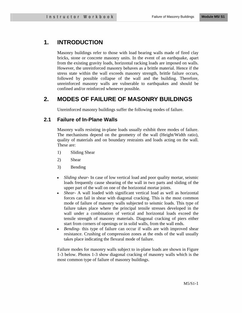
I n s t r u c t o r W o r k b o o k Failure of Masonry Buildings Module M5/ S1
M5/S1-1
1. INTRODUCTION Masonry buildings refer to those with load bearing walls made of fired clay bricks, stone or concrete masonry units. In the event of an earthquake, apart from the existing gravity loads, horizontal racking loads are imposed on walls. However, the unreinforced masonry behaves as a brittle material. Hence if the stress state within the wall exceeds masonry strength, brittle failure occurs, followed by possible collapse of the wall and the building. Therefore, unreinforced masonry walls are vulnerable to earthquakes and should be confined and/or reinforced whenever possible.
2. MODES OF FAILURE OF MASONRY BUILDINGS Unreinforced masonry buildings suffer the following modes of failure.
2.1 Failure of In-Plane Walls
Masonry walls resisting in-plane loads usually exhibit three modes of failure. The mechanisms depend on the geometry of the wall (Height/Width ratio), quality of materials and on boundary restraints and loads acting on the wall. These are:
1) Sliding Shear
2) Shear
3) Bending
• Sliding shear- In case of low vertical load and poor quality mortar, seismic loads frequently cause shearing of the wall in two parts and sliding of the upper part of the wall on one of the horizontal mortar joints.
• Shear- A wall loaded with significant vertical load as well as horizontal forces can fail in shear with diagonal cracking. This is the most common mode of failure of masonry walls subjected to seismic loads. This type of failure takes place where the principal tensile stresses developed in the wall under a combination of vertical and horizontal loads exceed the tensile strength of masonry materials. Diagonal cracking of piers either start from corners of openings or in solid walls, from the wall ends.
• Bending- this type of failure can occur if walls are with improved shear resistance. Crushing of compression zones at the ends of the wall usually takes place indicating the flexural mode of failure.
Failure modes for masonry walls subject to in-plane loads are shown in Figure 1-3 below. Photos 1-3 show diagonal cracking of masonry walls which is the most common type of failure of masonry buildings.
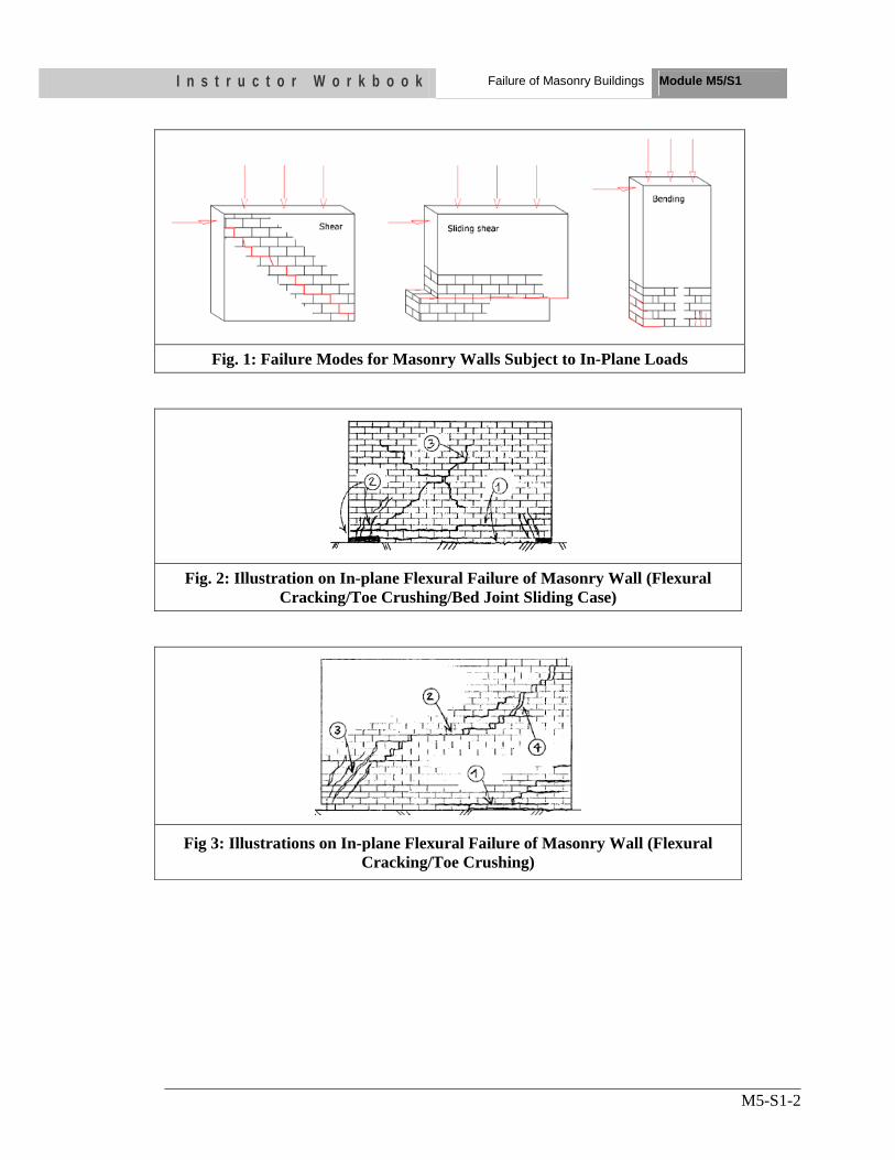
I n s t r u c t o r W o r k b o o k Failure of Masonry Buildings Module M5/S1
M5-S1-2
Fig. 1: Failure Modes for Masonry Walls Subject to In-Plane Loads
Fig. 2: Illustration on In-plane Flexural Failure of Masonry Wall (Flexural Cracking/Toe Crushing/Bed Joint Sliding Case)
Fig 3: Illustrations on In-plane Flexural Failure of Masonry Wall (Flexural Cracking/Toe Crushing)
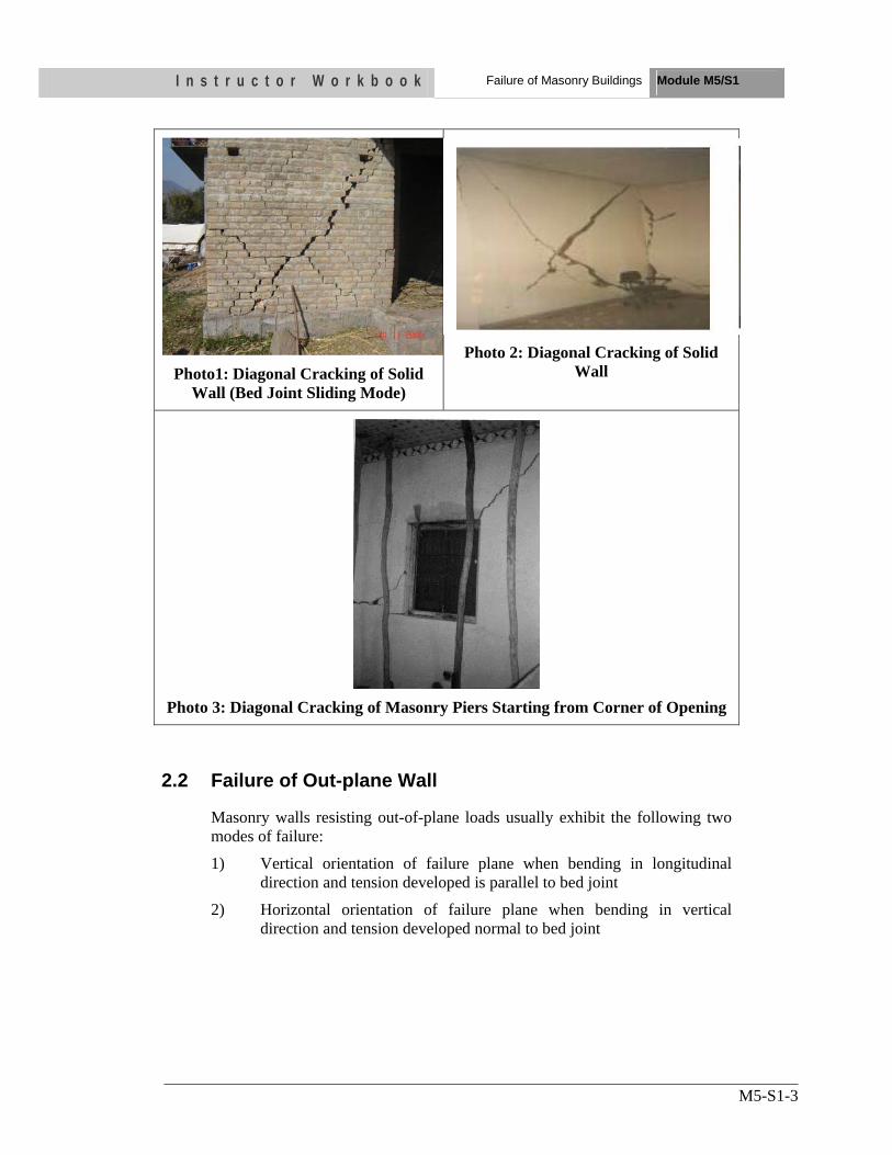
I n s t r u c t o r W o r k b o o k Failure of Masonry Buildings Module M5/S1
M5-S1-3
Photo1: Diagonal Cracking of Solid Wall (Bed Joint Sliding Mode)
Photo 2: Diagonal Cracking of Solid Wall
Photo 3: Diagonal Cracking of Masonry Piers Starting from Corner of Opening
2.2 Failure of Out-plane Wall
Masonry walls resisting out-of-plane loads usually exhibit the following two modes of failure:
1) Vertical orientation of failure plane when bending in longitudinal direction and tension developed is parallel to bed joint
2) Horizontal orientation of failure plane when bending in vertical direction and tension developed normal to bed joint
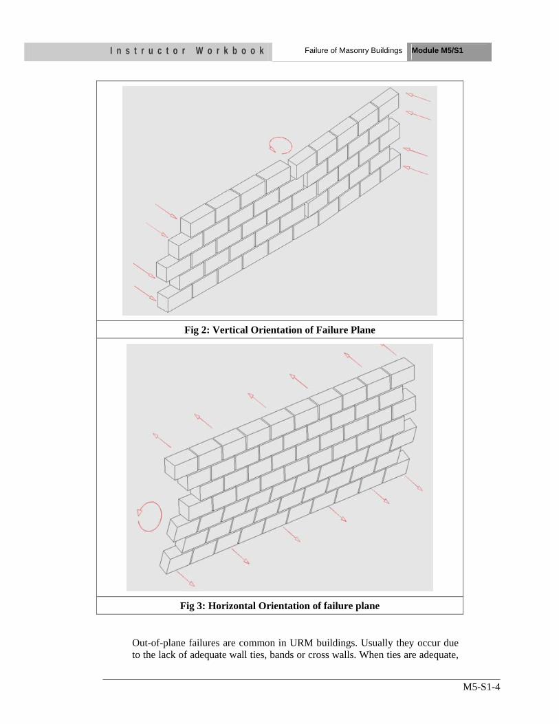
I n s t r u c t o r W o r k b o o k Failure of Masonry Buildings Module M5/S1
M5-S1-4
Fig 2: Vertical Orientation of Failure Plane
Fig 3: Horizontal Orientation of failure plane
Out-of-plane failures are common in URM buildings. Usually they occur due to the lack of adequate wall ties, bands or cross walls. When ties are adequate,
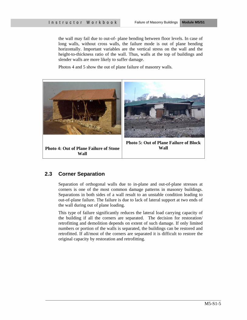
I n s t r u c t o r W o r k b o o k Failure of Masonry Buildings Module M5/S1
M5-S1-5
the wall may fail due to out-of- plane bending between floor levels. In case of long walls, without cross walls, the failure mode is out of plane bending horizontally. Important variables are the vertical stress on the wall and the height-to-thickness ratio of the wall. Thus, walls at the top of buildings and slender walls are more likely to suffer damage.
Photos 4 and 5 show the out of plane failure of masonry walls.
Photo 4: Out of Plane Failure of Stone Wall
Photo 5: Out of Plane Failure of Block Wall
2.3 Corner Separation
Separation of orthogonal walls due to in-plane and out-of-plane stresses at corners is one of the most common damage patterns in masonry buildings. Separations in both sides of a wall result to an unstable condition leading to out-of-plane failure. The failure is due to lack of lateral support at two ends of the wall during out of plane loading.
This type of failure significantly reduces the lateral load carrying capacity of the building if all the corners are separated. The decision for restoration/ retrofitting and demolition depends on extent of such damage. If only limited numbers or portion of the walls is separated, the buildings can be restored and retrofitted. If all/most of the corners are separated it is difficult to restore the original capacity by restoration and retrofitting.
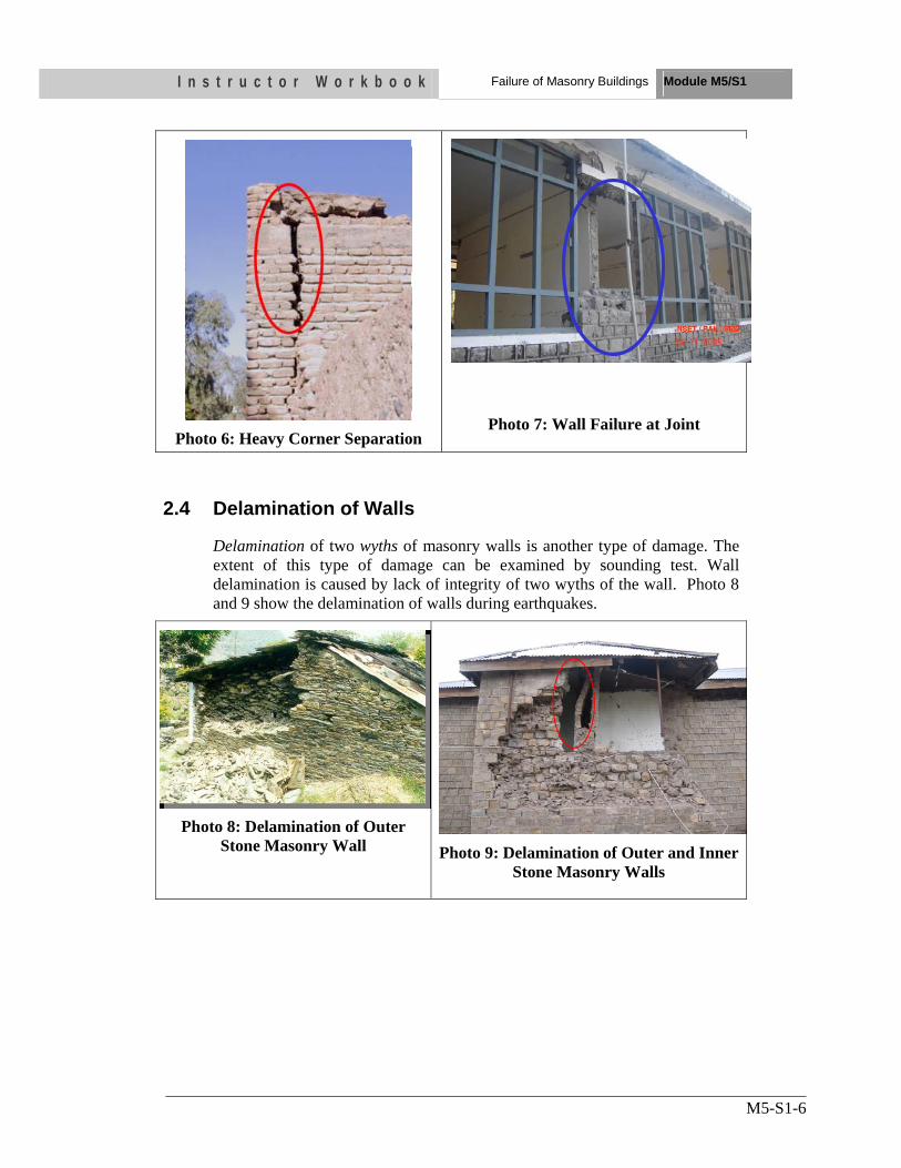
I n s t r u c t o r W o r k b o o k Failure of Masonry Buildings Module M5/S1
M5-S1-6
Photo 6: Heavy Corner Separation
Photo 7: Wall Failure at Joint
2.4 Delamination of Walls
Delamination of two wyths of masonry walls is another type of damage. The extent of this type of damage can be examined by sounding test. Wall delamination is caused by lack of integrity of two wyths of the wall. Photo 8 and 9 show the delamination of walls during earthquakes.
Photo 8: Delamination of Outer Stone Masonry Wall Photo 9: Delamination of Outer and Inner
Stone Masonry Walls
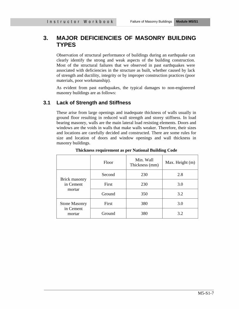
I n s t r u c t o r W o r k b o o k Failure of Masonry Buildings Module M5/S1
M5-S1-7
3. MAJOR DEFICIENCIES OF MASONRY BUILDING TYPES Observation of structural performance of buildings during an earthquake can clearly identify the strong and weak aspects of the building construction. Most of the structural failures that we observed in past earthquakes were associated with deficiencies in the structure as built, whether caused by lack of strength and ductility, integrity or by improper construction practices (poor materials, poor workmanship).
As evident from past earthquakes, the typical damages to non-engineered masonry buildings are as follows:
3.1 Lack of Strength and Stiffness
These arise from large openings and inadequate thickness of walls usually in ground floor resulting in reduced wall strength and storey stiffness. In load bearing masonry, walls are the main lateral load resisting elements. Doors and windows are the voids in walls that make walls weaker. Therefore, their sizes and locations are carefully decided and constructed. There are some rules for size and location of doors and window openings and wall thickness in masonry buildings.
Thickness requirement as per National Building Code
Floor Min. Wall Thickness (mm) Max. Height (m)
Brick masonry in Cement
mortar
Second 230 2.8
First 230 3.0
Ground 350 3.2
Stone Masonry in Cement
mortar
First 380 3.0
Ground 380 3.2
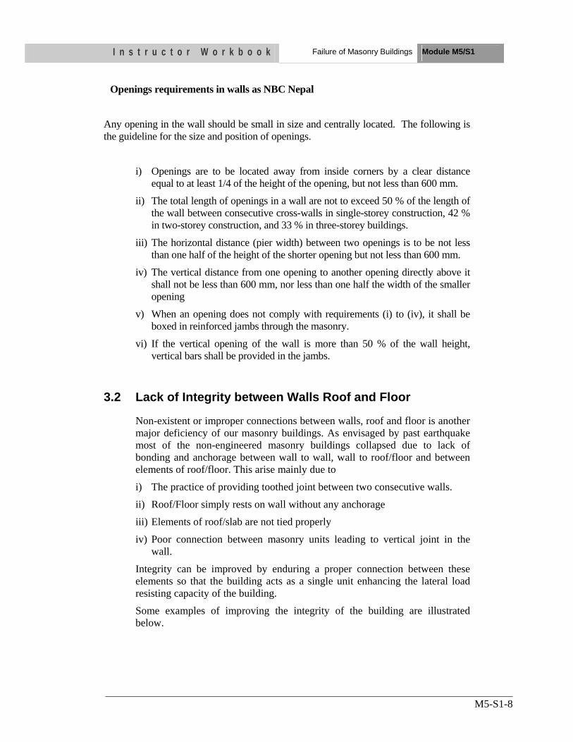
I n s t r u c t o r W o r k b o o k Failure of Masonry Buildings Module M5/S1
M5-S1-8
Openings requirements in walls as NBC Nepal
Any opening in the wall should be small in size and centrally located. The following is the guideline for the size and position of openings.
i) Openings are to be located away from inside corners by a clear distance equal to at least 1/4 of the height of the opening, but not less than 600 mm.
ii) The total length of openings in a wall are not to exceed 50 % of the length of the wall between consecutive cross-walls in single-storey construction, 42 % in two-storey construction, and 33 % in three-storey buildings.
iii) The horizontal distance (pier width) between two openings is to be not less than one half of the height of the shorter opening but not less than 600 mm.
iv) The vertical distance from one opening to another opening directly above it shall not be less than 600 mm, nor less than one half the width of the smaller opening
v) When an opening does not comply with requirements (i) to (iv), it shall be boxed in reinforced jambs through the masonry.
vi) If the vertical opening of the wall is more than 50 % of the wall height, vertical bars shall be provided in the jambs.
3.2 Lack of Integrity between Walls Roof and Floor
Non-existent or improper connections between walls, roof and floor is another major deficiency of our masonry buildings. As envisaged by past earthquake most of the non-engineered masonry buildings collapsed due to lack of bonding and anchorage between wall to wall, wall to roof/floor and between elements of roof/floor. This arise mainly due to
i) The practice of providing toothed joint between two consecutive walls.
ii) Roof/Floor simply rests on wall without any anchorage
iii) Elements of roof/slab are not tied properly
iv) Poor connection between masonry units leading to vertical joint in the wall.
Integrity can be improved by enduring a proper connection between these elements so that the building acts as a single unit enhancing the lateral load resisting capacity of the building.
Some examples of improving the integrity of the building are illustrated below.
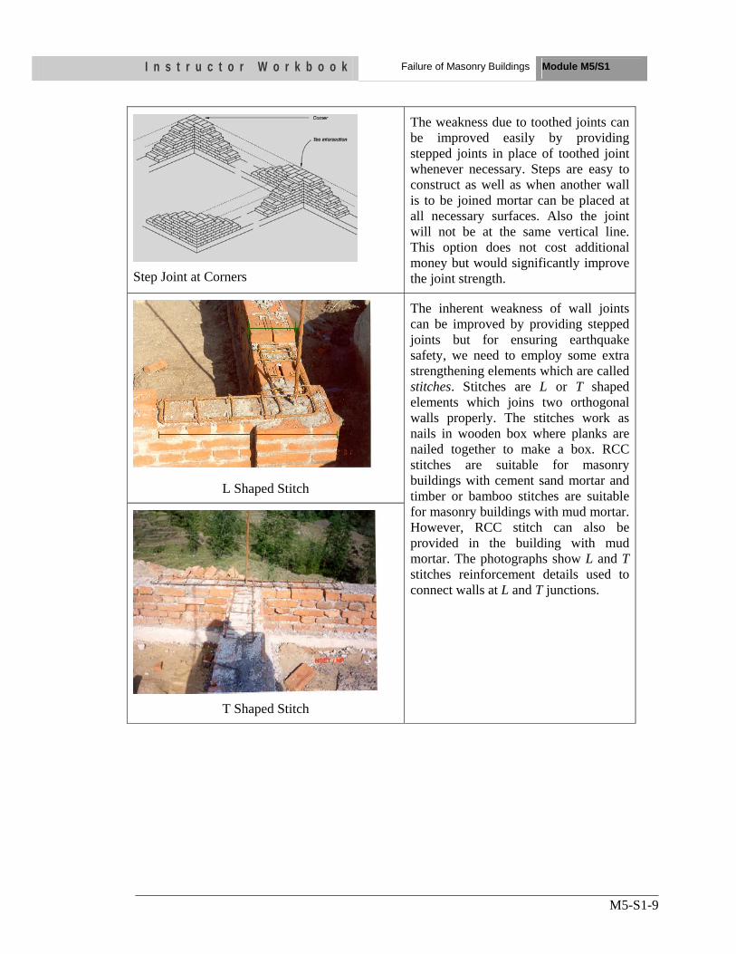
I n s t r u c t o r W o r k b o o k Failure of Masonry Buildings Module M5/S1
M5-S1-9
Step Joint at Corners
The weakness due to toothed joints can be improved easily by providing stepped joints in place of toothed joint whenever necessary. Steps are easy to construct as well as when another wall is to be joined mortar can be placed at all necessary surfaces. Also the joint will not be at the same vertical line. This option does not cost additional money but would significantly improve the joint strength.
L Shaped Stitch
The inherent weakness of wall joints can be improved by providing stepped joints but for ensuring earthquake safety, we need to employ some extra strengthening elements which are called stitches. Stitches are L or T shaped elements which joins two orthogonal walls properly. The stitches work as nails in wooden box where planks are nailed together to make a box. RCC stitches are suitable for masonry buildings with cement sand mortar and timber or bamboo stitches are suitable for masonry buildings with mud mortar. However, RCC stitch can also be provided in the building with mud mortar. The photographs show L and T stitches reinforcement details used to connect walls at L and T junctions.
T Shaped Stitch
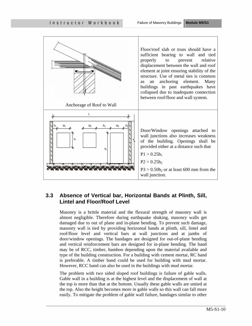
I n s t r u c t o r W o r k b o o k Failure of Masonry Buildings Module M5/S1
M5-S1-10
Anchorage of Roof to Wall
Floor/roof slab or truss should have a sufficient bearing to wall and tied properly to prevent relative displacement between the wall and roof element at joint ensuring stability of the structure. Use of metal ties is common as an anchoring element. Many buildings in past earthquakes have collapsed due to inadequate connection between roof/floor and wall system.
Door/Window openings attached to wall junctions also increases weakness of the building. Openings shall be provided either at a distance such that
P1 > 0.25h1
P2 > 0.25h2
P3 > 0.50h2 or at least 600 mm from the wall junction.
3.3 Absence of Vertical bar, Horizontal Bands at Plinth, Sill, Lintel and Floor/Roof Level
Masonry is a brittle material and the flexural strength of masonry wall is almost negligible. Therefore during earthquake shaking, masonry walls get damaged due to out of plane and in-plane bending. To prevent such damage, masonry wall is tied by providing horizontal bands at plinth, sill, lintel and roof/floor level and vertical bars at wall junctions and at jambs of door/window openings. The bandages are designed for out-of-plane bending and vertical reinforcement bars are designed for in-plane bending. The band may be of RCC, timber, bamboo depending upon the material available and type of the building construction. For a building with cement mortar, RC band is preferable. A timber band could be used for building with mud mortar. However, RCC band can also be used in the buildings with mud mortar.
The problem with two sided sloped roof buildings is failure of gable walls. Gable wall in a building is at the highest level and the displacement of wall at the top is more than that at the bottom. Usually these gable walls are untied at the top. Also the height becomes more in gable walls so this wall can fall more easily. To mitigate the problem of gable wall failure, bandages similar to other
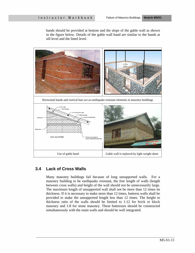
I n s t r u c t o r W o r k b o o k Failure of Masonry Buildings Module M5/S1
M5-S1-11
bands should be provided at bottom and the slope of the gable wall as shown in the figure below. Details of the gable wall band are similar to the bands at sill level and the lintel level.
Horizontal bands and vertical bars act as earthquake resistant elements in masonry buildings
Use of gable band Gable wall is replaced by light weight sheet
3.4 Lack of Cross Walls
Many masonry buildings fail because of long unsupported walls. For a masonry building to be earthquake resistant, the free length of walls (length between cross walls) and height of the wall should not be unnecessarily large. The maximum length of unsupported wall shall not be more than 12 times its thickness. If it is necessary to make more than 12 times, buttress walls shall be provided to make the unsupported length less than 12 times. The height to thickness ratio of the walls should be limited to 1:12 for brick or block masonry and 1:8 for stone masonry. These buttresses should be constructed simultaneously with the main walls and should be well integrated.
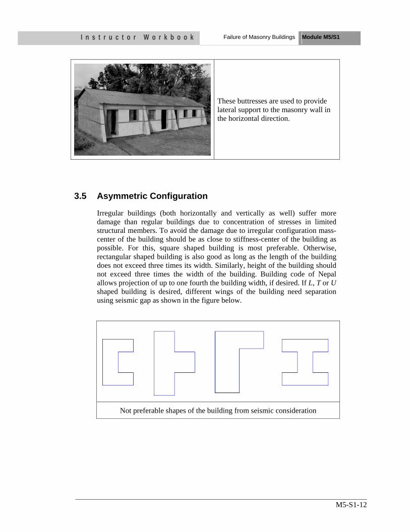
I n s t r u c t o r W o r k b o o k Failure of Masonry Buildings Module M5/S1
M5-S1-12
These buttresses are used to provide lateral support to the masonry wall in the horizontal direction.
3.5 Asymmetric Configuration
Irregular buildings (both horizontally and vertically as well) suffer more damage than regular buildings due to concentration of stresses in limited structural members. To avoid the damage due to irregular configuration mass-center of the building should be as close to stiffness-center of the building as possible. For this, square shaped building is most preferable. Otherwise, rectangular shaped building is also good as long as the length of the building does not exceed three times its width. Similarly, height of the building should not exceed three times the width of the building. Building code of Nepal allows projection of up to one fourth the building width, if desired. If L, T or U shaped building is desired, different wings of the building need separation using seismic gap as shown in the figure below.
Not preferable shapes of the building from seismic consideration
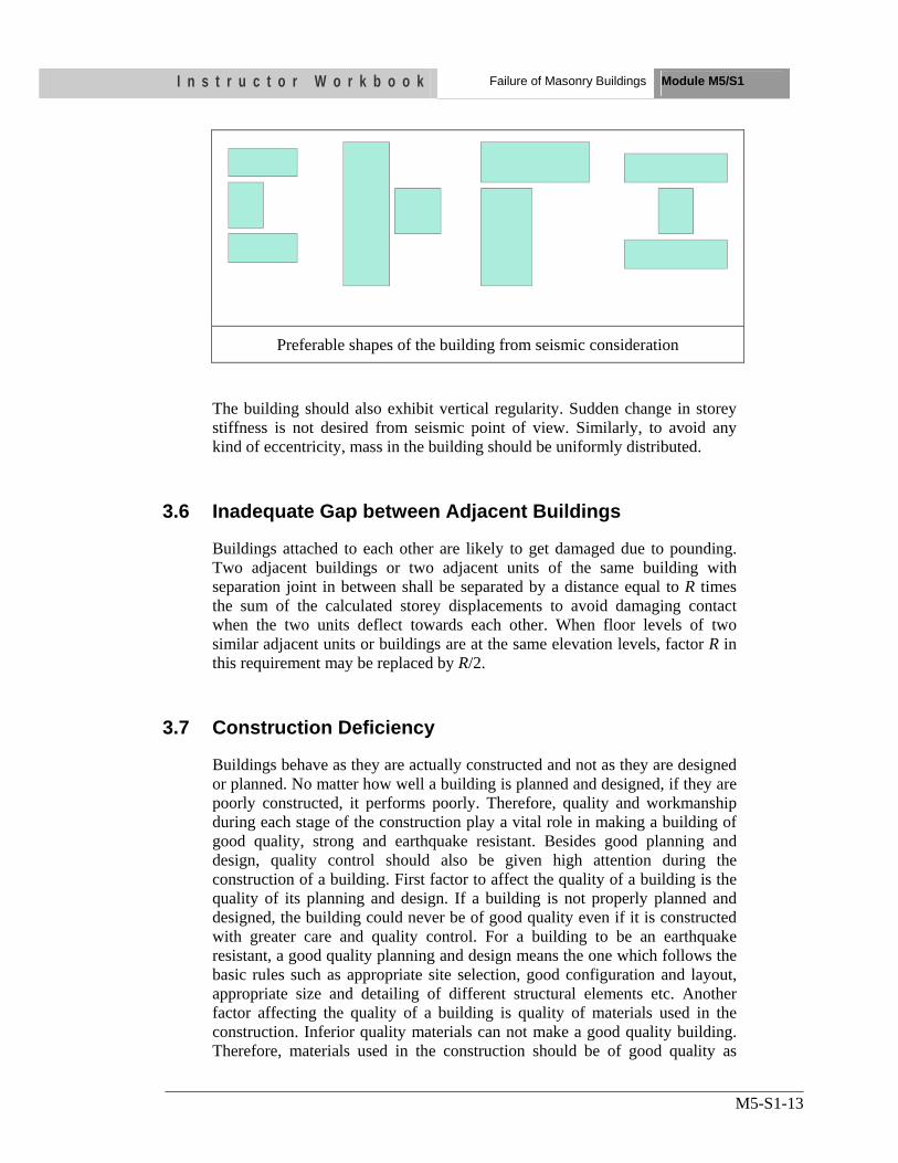
I n s t r u c t o r W o r k b o o k Failure of Masonry Buildings Module M5/S1
M5-S1-13
Preferable shapes of the building from seismic consideration
The building should also exhibit vertical regularity. Sudden change in storey stiffness is not desired from seismic point of view. Similarly, to avoid any kind of eccentricity, mass in the building should be uniformly distributed.
3.6 Inadequate Gap between Adjacent Buildings
Buildings attached to each other are likely to get damaged due to pounding. Two adjacent buildings or two adjacent units of the same building with separation joint in between shall be separated by a distance equal to R times the sum of the calculated storey displacements to avoid damaging contact when the two units deflect towards each other. When floor levels of two similar adjacent units or buildings are at the same elevation levels, factor R in this requirement may be replaced by R/2.
3.7 Construction Deficiency
Buildings behave as they are actually constructed and not as they are designed or planned. No matter how well a building is planned and designed, if they are poorly constructed, it performs poorly. Therefore, quality and workmanship during each stage of the construction play a vital role in making a building of good quality, strong and earthquake resistant. Besides good planning and design, quality control should also be given high attention during the construction of a building. First factor to affect the quality of a building is the quality of its planning and design. If a building is not properly planned and designed, the building could never be of good quality even if it is constructed with greater care and quality control. For a building to be an earthquake resistant, a good quality planning and design means the one which follows the basic rules such as appropriate site selection, good configuration and layout, appropriate size and detailing of different structural elements etc. Another factor affecting the quality of a building is quality of materials used in the construction. Inferior quality materials can not make a good quality building. Therefore, materials used in the construction should be of good quality as
I n s t r u c t o r W o r k b o o k Failure of Masonry Buildings Module M5/S1
M5-S1-14
mentioned in the specifications. Next major factor to contribute in the quality of a building is the quality of construction process and quality of workmanship. This is the ultimate factor to make a good quality building. Each and every stage of the construction should be in accordance with the provisions and steps mentioned in the standard construction manuals and guidelines. Resources and time available are the indirect factors to make a good quality building. Experiences have shown that if the project period is prolonged due to the resource constraints, the quality of construction goes on decreasing.
I n s t r u c t o r W o r k b o o k Failure of Masonry Buildings Module M5/S1
M5-S1-15
UNIT TEST 1) Describe three modes of failure of masonry walls resisting in in-plane
loads
• ……
2) Describe five major deficiencies of masonry buildings
• ……
OBJECTIVES As a result of this session, you should be able to:
•• IIddeennttiiffyy tthhee sstteeppss ooff qquuaalliittaattiivvee aasssseessssmmeenntt
• IIddeennttiiffyy mmaajjoorr bbuuiillddiinngg ttyyppeess iinn NNeeppaall
• DDeessccrriibbee ffrraaggiilliittyy ccuurrvveess ooff ddiiffffeerreenntt ttyyppeess ooff bbuuiillddiinngg
• IIddeennttiiffyy ddiiffffeerreenntt vvuullnneerraabbiilliittyy ffaaccttoorrss ooff tthhee bbuuiillddiinngg
•• LLiisstt 55 ddaammaaggee ggrraaddeess
Instructor Workbook Module M6/ S1
Qualitative Seismic Vulnerability Assessment of the Building
CONTENTS
1. INTRODUCTION ............................................................................................ 3 2. STEPS OF QUALITATIVE ASSESSMENT PROCESS ............................. 3
2.1 Evaluation of Site Hazards ....................................................................... 3
2.2 Establish Seismic Target Performance Level ........................................... 3
2.3 Identification of Building Type ................................................................ 4
2.4 Selection of Appropriate Fragility Curves of the Building ....................... 5
2.5 Identification of Vulnerability Factors ..................................................... 7
2.5.1 Structural Assessment Checklist for Type 4 and Type 5 Buildings ....................................................................................... 7
2.5.2 Structural Assessment Checklist for Type 2 Buildings ............... 10
2.6 Reinterpretation of the Building Fragility Based on Observed Vulnerability Factors .............................................................................. 14
I n s t r u c t o r W o r k b o o k Qualitative seismic vulnerability
assessment Module M6/S1
M6/S1-3
1. INTRODUCTION Seismic vulnerability assessment is the identification of probable performance/behavior of the building during different intensities of earthquake shaking and the evaluation of reliability of the building in earthquake. The main aim is to identify immediate risk underlying in the building in terms of life safety. The qualitative seismic assessment is the preliminary evaluation process and is based more on a subjective approach in identifying the areas of seismic deficiencies in a building before a detailed evaluation. This evaluation process is performed to determine whether the building, in its existing condition, has the desired seismic performance capability. A method of evaluation basically involves review of available drawings and visual evaluation of the building from the perspective of damage that it could suffer in the event of an earthquake. It checks the code compliance for seismic design and detailing. This will help in deciding the retrofitting requirements for the building. 2. STEPS OF QUALITATIVE ASSESSMENT PROCESS Qualitative structural assessment of the building shall be done based on visual observation at site, review of all available documents and drawings pertaining to the design and construction, design details observed during field visit at site. If no documents are available, an as-built set of drawing shall be prepared indicating the existing lateral force resisting system. If the records are not available, an attempt can be made to obtain some information based on interviews with those who were involved in the design and construction of the building or familiar with the contemporary methods of construction, and the owners/residents. Different seismic vulnerability factors are checked and expected performance of the building is estimated for different intensities of earthquake. Different steps of the assessment process are described below.
2.1 Evaluation of Site Hazards
The region of seismicity, liquefaction potential and other possible hazards of the building shall be identified. This is done locating the building in seismic hazard map, liquefaction map and other flood zone maps etc. of the region in which the building stands. The seismic zone map of Nepal is provided in Nepal National Building Code NBC 105: 1994.
2.2 Establish Seismic Target Performance Level
Performance level desired is established in level of protection prior to conducting seismic evaluation and strengthening. These are classified as:
• Operational • Immediate occupancy • Life safety • Collapse Prevention
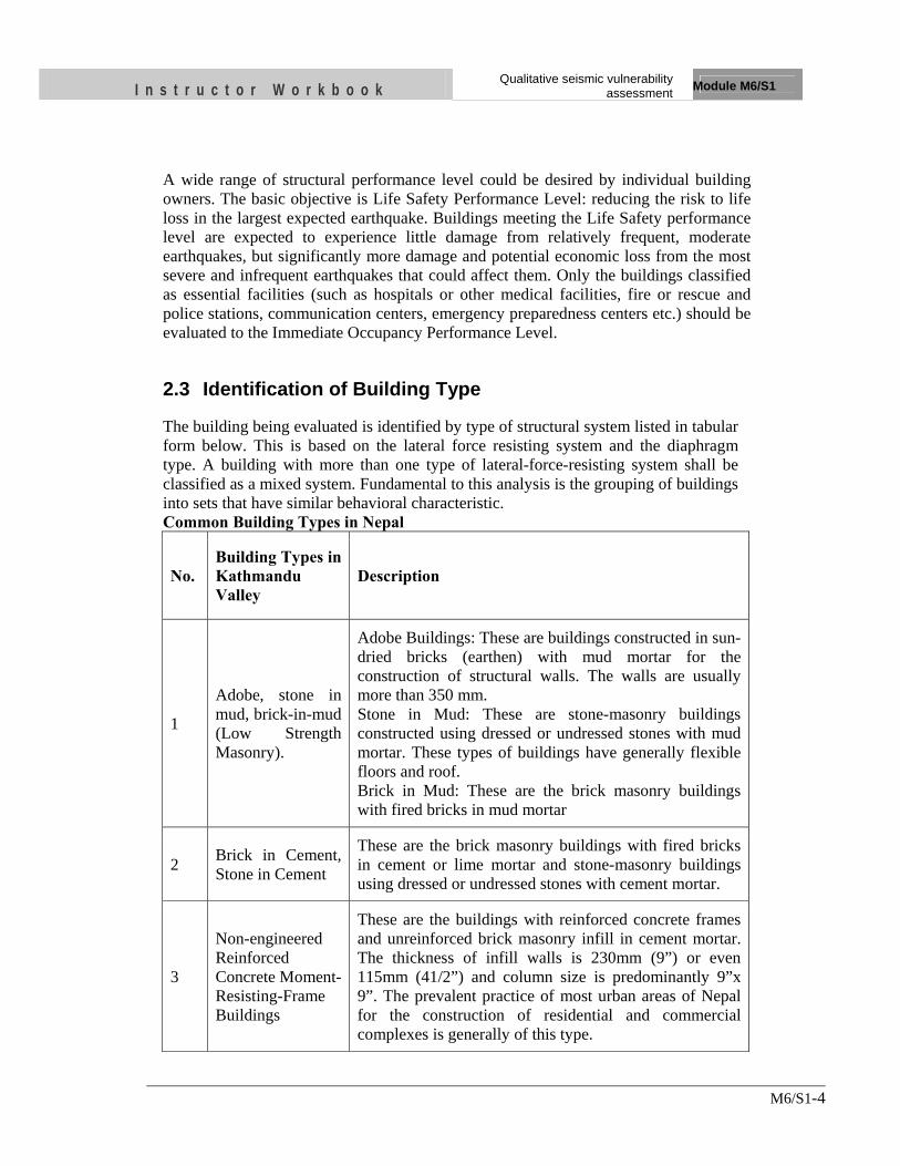
I n s t r u c t o r W o r k b o o k Qualitative seismic vulnerability
assessment Module M6/S1
M6/S1-4
A wide range of structural performance level could be desired by individual building owners. The basic objective is Life Safety Performance Level: reducing the risk to life loss in the largest expected earthquake. Buildings meeting the Life Safety performance level are expected to experience little damage from relatively frequent, moderate earthquakes, but significantly more damage and potential economic loss from the most severe and infrequent earthquakes that could affect them. Only the buildings classified as essential facilities (such as hospitals or other medical facilities, fire or rescue and police stations, communication centers, emergency preparedness centers etc.) should be evaluated to the Immediate Occupancy Performance Level.
2.3 Identification of Building Type
The building being evaluated is identified by type of structural system listed in tabular form below. This is based on the lateral force resisting system and the diaphragm type. A building with more than one type of lateral-force-resisting system shall be classified as a mixed system. Fundamental to this analysis is the grouping of buildings into sets that have similar behavioral characteristic. Common Building Types in Nepal
No. Building Types in Kathmandu Valley
Description
1
Adobe, stone in mud, brick-in-mud (Low Strength Masonry).
Adobe Buildings: These are buildings constructed in sun-dried bricks (earthen) with mud mortar for the construction of structural walls. The walls are usually more than 350 mm. Stone in Mud: These are stone-masonry buildings constructed using dressed or undressed stones with mud mortar. These types of buildings have generally flexible floors and roof. Brick in Mud: These are the brick masonry buildings with fired bricks in mud mortar
2 Brick in Cement, Stone in Cement
These are the brick masonry buildings with fired bricks in cement or lime mortar and stone-masonry buildings using dressed or undressed stones with cement mortar.
3
Non-engineered Reinforced Concrete Moment-Resisting-Frame Buildings
These are the buildings with reinforced concrete frames and unreinforced brick masonry infill in cement mortar. The thickness of infill walls is 230mm (9”) or even 115mm (41/2”) and column size is predominantly 9”x 9”. The prevalent practice of most urban areas of Nepal for the construction of residential and commercial complexes is generally of this type.
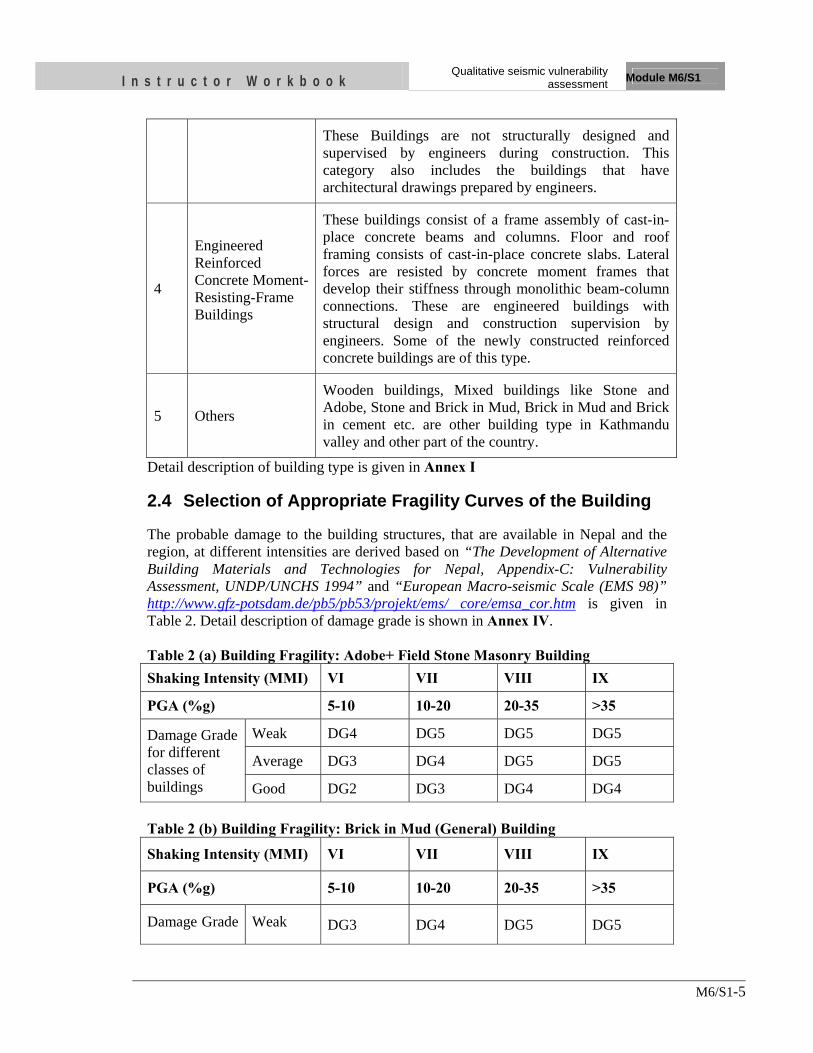
I n s t r u c t o r W o r k b o o k Qualitative seismic vulnerability
assessment Module M6/S1
M6/S1-5
These Buildings are not structurally designed and supervised by engineers during construction. This category also includes the buildings that have architectural drawings prepared by engineers.
4
Engineered Reinforced Concrete Moment-Resisting-Frame Buildings
These buildings consist of a frame assembly of cast-in-place concrete beams and columns. Floor and roof framing consists of cast-in-place concrete slabs. Lateral forces are resisted by concrete moment frames that develop their stiffness through monolithic beam-column connections. These are engineered buildings with structural design and construction supervision by engineers. Some of the newly constructed reinforced concrete buildings are of this type.
5 Others
Wooden buildings, Mixed buildings like Stone and Adobe, Stone and Brick in Mud, Brick in Mud and Brick in cement etc. are other building type in Kathmandu valley and other part of the country.
Detail description of building type is given in Annex I
2.4 Selection of Appropriate Fragility Curves of the Building
The probable damage to the building structures, that are available in Nepal and the region, at different intensities are derived based on “The Development of Alternative Building Materials and Technologies for Nepal, Appendix-C: Vulnerability Assessment, UNDP/UNCHS 1994” and “European Macro-seismic Scale (EMS 98)” http://www.gfz-potsdam.de/pb5/pb53/projekt/ems/ core/emsa_cor.htm is given in Table 2. Detail description of damage grade is shown in Annex IV. Table 2 (a) Building Fragility: Adobe+ Field Stone Masonry Building Shaking Intensity (MMI) VI VII VIII IX
PGA (%g) 5-10 10-20 20-35 >35
Damage Grade for different classes of buildings
Weak DG4 DG5 DG5 DG5
Average DG3 DG4 DG5 DG5
Good DG2 DG3 DG4 DG4 Table 2 (b) Building Fragility: Brick in Mud (General) Building
Shaking Intensity (MMI) VI VII VIII IX
PGA (%g) 5-10 10-20 20-35 >35
Damage Grade Weak DG3 DG4 DG5 DG5
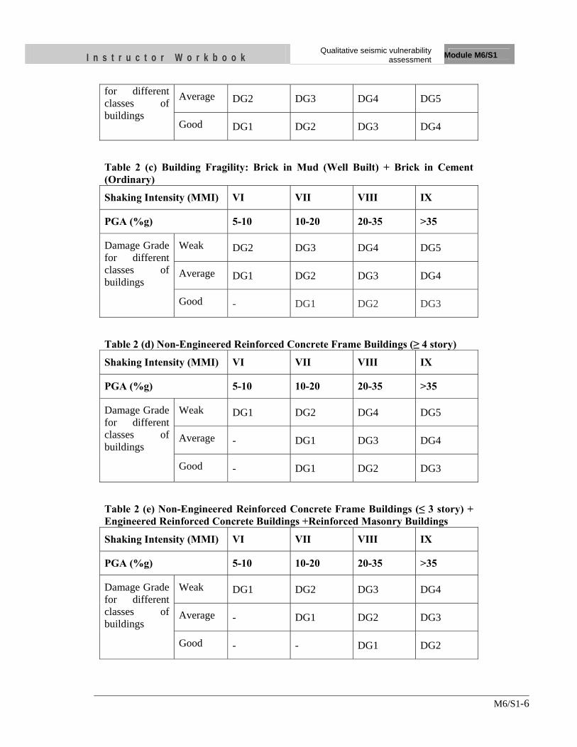
I n s t r u c t o r W o r k b o o k Qualitative seismic vulnerability
assessment Module M6/S1
M6/S1-6
for different classes of buildings
Average DG2 DG3 DG4 DG5
Good DG1 DG2 DG3 DG4
Table 2 (c) Building Fragility: Brick in Mud (Well Built) + Brick in Cement (Ordinary)
Shaking Intensity (MMI) VI VII VIII IX
PGA (%g) 5-10 10-20 20-35 >35
Damage Grade for different classes of buildings
Weak DG2 DG3 DG4 DG5
Average DG1 DG2 DG3 DG4
Good - DG1 DG2 DG3
Table 2 (d) Non-Engineered Reinforced Concrete Frame Buildings (≥ 4 story)
Shaking Intensity (MMI) VI VII VIII IX
PGA (%g) 5-10 10-20 20-35 >35
Damage Grade for different classes of buildings
Weak DG1 DG2 DG4 DG5
Average - DG1 DG3 DG4
Good - DG1 DG2 DG3
Table 2 (e) Non-Engineered Reinforced Concrete Frame Buildings (≤ 3 story) + Engineered Reinforced Concrete Buildings +Reinforced Masonry Buildings
Shaking Intensity (MMI) VI VII VIII IX
PGA (%g) 5-10 10-20 20-35 >35
Damage Grade for different classes of buildings
Weak DG1 DG2 DG3 DG4
Average - DG1 DG2 DG3
Good - - DG1 DG2
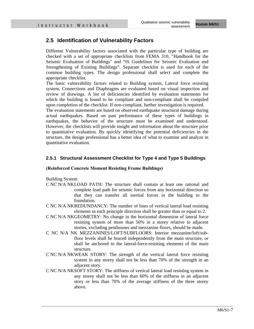
I n s t r u c t o r W o r k b o o k Qualitative seismic vulnerability
assessment Module M6/S1
M6/S1-7
2.5 Identification of Vulnerability Factors
Different Vulnerability factors associated with the particular type of building are checked with a set of appropriate checklists from FEMA 310, "Handbook for the Seismic Evaluation of Buildings" and “IS Guidelines for Seismic Evaluation and Strengthening of Existing Buildings”. Separate checklist is used for each of the common building types. The design professional shall select and complete the appropriate checklist. The basic vulnerability factors related to Building system, Lateral force resisting system, Connections and Diaphragms are evaluated based on visual inspection and review of drawings. A list of deficiencies identified by evaluation statements for which the building is found to be compliant and non-compliant shall be compiled upon completion of the checklist. If non-compliant, further investigation is required. The evaluation statements are based on observed earthquake structural damage during actual earthquakes. Based on past performance of these types of buildings in earthquakes, the behavior of the structure must be examined and understood. However, the checklists will provide insight and information about the structure prior to quantitative evaluation. By quickly identifying the potential deficiencies in the structure, the design professional has a better idea of what to examine and analyze in quantitative evaluation.
2.5.1 Structural Assessment Checklist for Type 4 and Type 5 Buildings
(Reinforced Concrete Moment Resisting Frame Buildings) Building System C NC N/A NK LOAD PATH: The structure shall contain at least one rational and
complete load path for seismic forces from any horizontal direction so that they can transfer all inertial forces in the building to the foundation.
C NC N/A NK REDUNDANCY: The number of lines of vertical lateral load resisting elements in each principle direction shall be greater than or equal to 2.
C NC N/A NK GEOMETRY: No change in the horizontal dimension of lateral force resisting system of more than 50% in a storey relative to adjacent stories, excluding penthouses and mezzanine floors, should be made.
C NC N/A NK MEZZANINES/LOFT/SUBFLOORS: Interior mezzanine/loft/sub-floor levels shall be braced independently from the main structure, or shall be anchored to the lateral-force-resisting elements of the main structure.
C NC N/A NK WEAK STORY: The strength of the vertical lateral force resisting system in any storey shall not be less than 70% of the strength in an adjacent story.
C NC N/A NK SOFT STORY: The stiffness of vertical lateral load resisting system in any storey shall not be less than 60% of the stiffness in an adjacent story or less than 70% of the average stiffness of the three storey above.
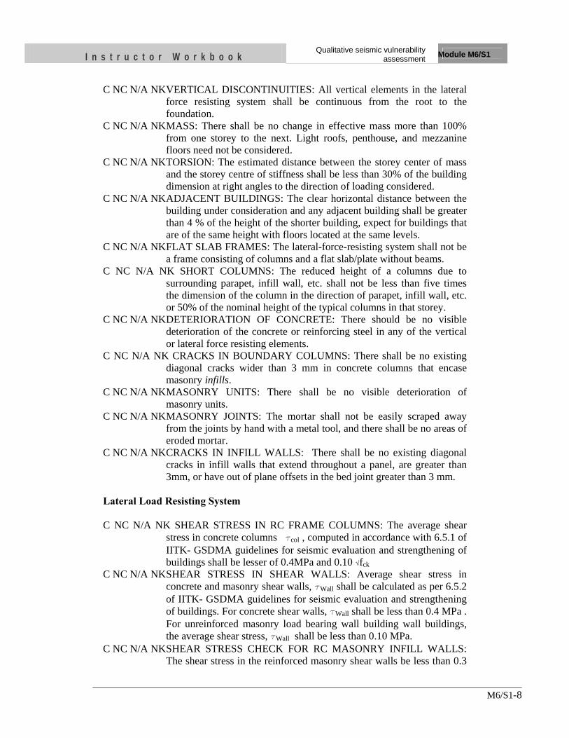
I n s t r u c t o r W o r k b o o k Qualitative seismic vulnerability
assessment Module M6/S1
M6/S1-8
C NC N/A NK VERTICAL DISCONTINUITIES: All vertical elements in the lateral force resisting system shall be continuous from the root to the foundation.
C NC N/A NK MASS: There shall be no change in effective mass more than 100% from one storey to the next. Light roofs, penthouse, and mezzanine floors need not be considered.
C NC N/A NK TORSION: The estimated distance between the storey center of mass and the storey centre of stiffness shall be less than 30% of the building dimension at right angles to the direction of loading considered.
C NC N/A NK ADJACENT BUILDINGS: The clear horizontal distance between the building under consideration and any adjacent building shall be greater than 4 % of the height of the shorter building, expect for buildings that are of the same height with floors located at the same levels.
C NC N/A NK FLAT SLAB FRAMES: The lateral-force-resisting system shall not be a frame consisting of columns and a flat slab/plate without beams.
C NC N/A NK SHORT COLUMNS: The reduced height of a columns due to surrounding parapet, infill wall, etc. shall not be less than five times the dimension of the column in the direction of parapet, infill wall, etc. or 50% of the nominal height of the typical columns in that storey.
C NC N/A NK DETERIORATION OF CONCRETE: There should be no visible deterioration of the concrete or reinforcing steel in any of the vertical or lateral force resisting elements.
C NC N/A NK CRACKS IN BOUNDARY COLUMNS: There shall be no existing diagonal cracks wider than 3 mm in concrete columns that encase masonry infills.
C NC N/A NK MASONRY UNITS: There shall be no visible deterioration of masonry units.
C NC N/A NK MASONRY JOINTS: The mortar shall not be easily scraped away from the joints by hand with a metal tool, and there shall be no areas of eroded mortar.
C NC N/A NK CRACKS IN INFILL WALLS: There shall be no existing diagonal cracks in infill walls that extend throughout a panel, are greater than 3mm, or have out of plane offsets in the bed joint greater than 3 mm.
Lateral Load Resisting System C NC N/A NK SHEAR STRESS IN RC FRAME COLUMNS: The average shear
stress in concrete columns tcol , computed in accordance with 6.5.1 of IITK- GSDMA guidelines for seismic evaluation and strengthening of buildings shall be lesser of 0.4MPa and 0.10 √fck
C NC N/A NK SHEAR STRESS IN SHEAR WALLS: Average shear stress in concrete and masonry shear walls, tWall shall be calculated as per 6.5.2 of IITK- GSDMA guidelines for seismic evaluation and strengthening of buildings. For concrete shear walls, tWall shall be less than 0.4 MPa . For unreinforced masonry load bearing wall building wall buildings, the average shear stress, tWall shall be less than 0.10 MPa.
C NC N/A NK SHEAR STRESS CHECK FOR RC MASONRY INFILL WALLS: The shear stress in the reinforced masonry shear walls be less than 0.3
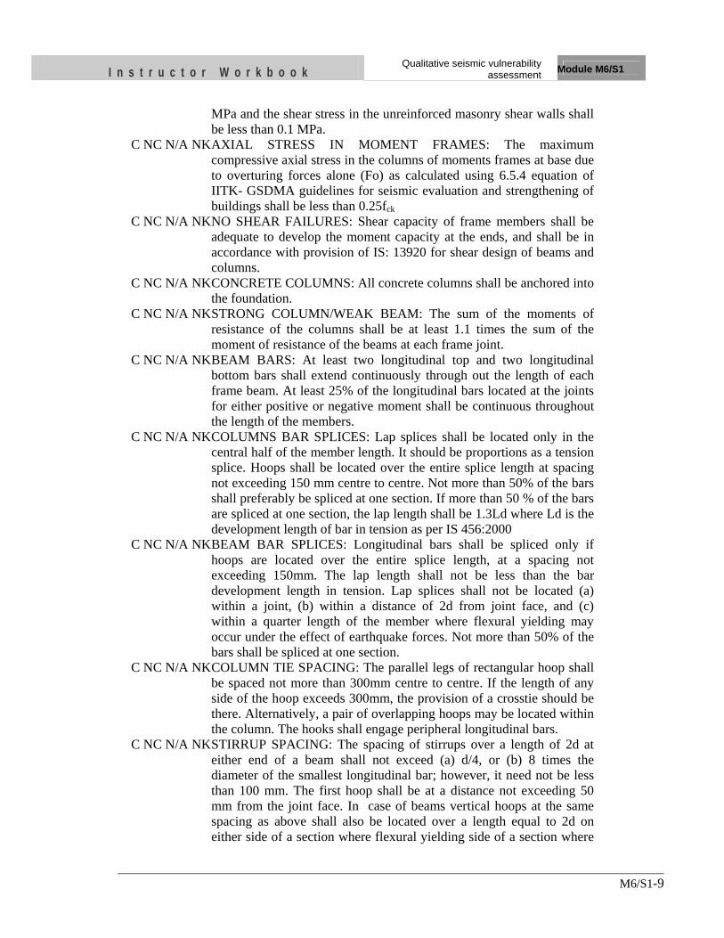
I n s t r u c t o r W o r k b o o k Qualitative seismic vulnerability
assessment Module M6/S1
M6/S1-9
MPa and the shear stress in the unreinforced masonry shear walls shall be less than 0.1 MPa.
C NC N/A NK AXIAL STRESS IN MOMENT FRAMES: The maximum compressive axial stress in the columns of moments frames at base due to overturing forces alone (Fo) as calculated using 6.5.4 equation of IITK- GSDMA guidelines for seismic evaluation and strengthening of buildings shall be less than 0.25fck
C NC N/A NK NO SHEAR FAILURES: Shear capacity of frame members shall be adequate to develop the moment capacity at the ends, and shall be in accordance with provision of IS: 13920 for shear design of beams and columns.
C NC N/A NK CONCRETE COLUMNS: All concrete columns shall be anchored into the foundation.
C NC N/A NK STRONG COLUMN/WEAK BEAM: The sum of the moments of resistance of the columns shall be at least 1.1 times the sum of the moment of resistance of the beams at each frame joint.
C NC N/A NK BEAM BARS: At least two longitudinal top and two longitudinal bottom bars shall extend continuously through out the length of each frame beam. At least 25% of the longitudinal bars located at the joints for either positive or negative moment shall be continuous throughout the length of the members.
C NC N/A NK COLUMNS BAR SPLICES: Lap splices shall be located only in the central half of the member length. It should be proportions as a tension splice. Hoops shall be located over the entire splice length at spacing not exceeding 150 mm centre to centre. Not more than 50% of the bars shall preferably be spliced at one section. If more than 50 % of the bars are spliced at one section, the lap length shall be 1.3Ld where Ld is the development length of bar in tension as per IS 456:2000
C NC N/A NK BEAM BAR SPLICES: Longitudinal bars shall be spliced only if hoops are located over the entire splice length, at a spacing not exceeding 150mm. The lap length shall not be less than the bar development length in tension. Lap splices shall not be located (a) within a joint, (b) within a distance of 2d from joint face, and (c) within a quarter length of the member where flexural yielding may occur under the effect of earthquake forces. Not more than 50% of the bars shall be spliced at one section.
C NC N/A NK COLUMN TIE SPACING: The parallel legs of rectangular hoop shall be spaced not more than 300mm centre to centre. If the length of any side of the hoop exceeds 300mm, the provision of a crosstie should be there. Alternatively, a pair of overlapping hoops may be located within the column. The hooks shall engage peripheral longitudinal bars.
C NC N/A NK STIRRUP SPACING: The spacing of stirrups over a length of 2d at either end of a beam shall not exceed (a) d/4, or (b) 8 times the diameter of the smallest longitudinal bar; however, it need not be less than 100 mm. The first hoop shall be at a distance not exceeding 50 mm from the joint face. In case of beams vertical hoops at the same spacing as above shall also be located over a length equal to 2d on either side of a section where flexural yielding side of a section where
I n s t r u c t o r W o r k b o o k Qualitative seismic vulnerability
assessment Module M6/S1
M6/S1-10
flexural yielding may occur under the effect of earthquake forces. Elsewhere, the beam shall have vertical hoops at a spacing not exceeding d/2.
C NC N/A NK JOINT REINFORCING: Beam- column joints shall have ties spaced at or less than 150 mm.
C NC N/A NK STIRRUP AND TIE HOOKS: The beam stirrups and column ties shall preferably be anchored into the member cores with hooks of 1350
C NC N/A NK JOINT ECCENTRICITY: There shall be no eccentricities larger than 20% of the smallest column plan dimension between girder and column centerlines. This statement shall apply to the Immediate Occupancy Performance Level only.
C NC N/A NK WALL CONNECTIONS: All infill walls shall have a positive connection to the frame to resist out-of-plane forces.
C NC N/A NK INTERFERING WALLS: All infill walls placed in moment frames shall be isolated from structural elements.
Diaphragms C NC N/A NK DIAPHRAGM CONTINUITY: The diaphragms shall not be
composed of split-level floors. In wood buildings, the diaphragms shall not have expansion joints.
C NC N/A NK PLAN IRREGULARITIES: There shall be tensile capacity to develop the strength of the diaphragm at re-entrant corners or other locations of plan irregularities. This statement shall apply to the Immediate Occupancy Performance Level only.
C NC N/A NK DIAPHRAGM REINFORCEMENT AT OPENINGS: There shall be reinforcing around all diaphragms openings larger than 50% of the building width in either major plan dimension. This statement shall apply to the Immediate Occupancy Performance Level only.
Geologic Site C NC N/A NK AREA HISTORY: Evidence of history of landslides, mud slides, soil
settlement, sinkholes, construction on fill, or buried on or at sites in the area are not anticipated.
C NC N/A NK LIQUEFACTION: Liquefaction susceptible, saturated, loose granular soils that could jeopardize the building’s seismic performance shall not exist in the foundation soils.
C NC N/A NK SLOPE FAILURE: The building site shall be sufficiently remote from potential earthquake induced slope failures or rockfalls to be unaffected by such failures or shall be capable of accommodating any predicted movements without failure.
2.5.2 Structural Assessment Checklist for Type 2 Buildings
(Brick in Cement Buildings and Stone in Cement Buildings)

I n s t r u c t o r W o r k b o o k Qualitative seismic vulnerability
assessment Module M6/S1
M6/S1-11
C NC N/A NK LOAD PATH: The structure shall contain at least one rational and complete load path for seismic forces from any horizontal direction so that they can transfer all inertial forces in the building to the foundation.
C NC N/A NK REDUNDANCY: The number of lines of vertical lateral load resisting elements in each principal direction shall be greater than or equal to 2. Similarly, the number of lines of shear walls in each direction shall be greater than or equal to 2.
C NC N/A NK GEOMETRY: No change in the horizontal dimension of lateral force resisting system of more than 50% in a storey relative to adjacent stories, excluding penthouses and mezzanine floors, should be made.
C NC N/A NK MEZZANINES/LOFT/SUBFLOORS: Interior mezzanine/loft/sub-floor levels shall be braced independently from the main structure, or shall be anchored to the lateral-force-resisting elements of the main structure.
C NC N/A NK WEAK STORY: The strength of the vertical lateral force resisting system in any storey shall not be less than 70% of the strength in an adjacent story.
C NC N/A NK SOFT STORY: The stiffness of the vertical lateral load resisting system in any storey shall not be less than 60% of the stiffness in an adjacent story above or less than 70% of the average stiffness of the three storey above.
C NC N/A NK VERTICAL DISCONTINUITIES: All vertical elements in the lateral force resisting system shall be continuous from the root to the foundation.
C NC N/A NK MASS: There shall be no change in effective mass more than 100% from one storey to the next. Light roofs, penthouse, and mezzanine floors need not be considered.
C NC N/A NK TORSION: The estimated distance between the storey center of mass and the storey centre of stiffness shall be less than 30% of the building dimension at right angles to the direction of loading considered.
C NC N/A NK ADJACENT BUILDINGS: The clear horizontal distance between the building under consideration and any adjacent building shall be greater than 4 % of the height of the shorter building, expect for buildings that are of the same height with floors located at the same levels.
C NC N/A NK DETERIORATION OF CONCRETE: There should be no visible deterioration of the concrete or reinforcing steel in any of the vertical or lateral force resisting elements.
C NC N/A NK MASONRY UNITS: There shall be no visible deterioration of masonry units.
C NC N/A NK MASONRY JOINTS: The motar shall not be easily scraped away from the joints by hand with a metal tool, and there shall be no areas of eroded mortar.
C NC N/A NK UNREINFORCED MASONRY WALL CRACKS: There shall be no existing diagonal cracks in wall elements greater than 1/8" for Life Safety and 1/16" for Immediate Occupancy or out-of-plane offsets in the bed joint greater than 1/8" for Life Safety and 1/16" for Immediate Occupancy.
I n s t r u c t o r W o r k b o o k Qualitative seismic vulnerability
assessment Module M6/S1
M6/S1-12
Lateral Load Resisting System C NC N/A NK SHEAR STRESS IN SHEAR WALLS: Average shear stress in
masonry shear walls, tWall shall be calculated as per 6.5.2 of IITK- GSDMA guidelines for seismic evaluation and strengthening of buildings. For unreinforced masonry load bearing wall building, the average shear stress, tWall shall be less than 0.10MPa.
C NC N/A NK HEIGHT TO THICKNESS RATIO: The unreinforced masonry wall height-to-thickness ratios shall be less than the following.
Top storey of multi storey building: 9 First storey of multi storey building: 15 All other conditions: 13 C NC N/A NK MASONRY LAY UP: Filled collar joints of multi wythe masonry
walls shall have negligible voids. C NC N/A NK WALL ANCHORAGE: Walls shall be properly anchored to
diaphragms for out of plane forces with anchor spacing of 1.2 m or less.
C NC N/A NK CONNECTIONS: Diaphragms shall be reinforced and connected to transfer of loads to the shear walls.
C NC N/A NK OPENINGS IN DIAPHRAGMS NEAR SHEAR WALLS: Diaphragm openings immediately adjacent to the shear walls shall be less than 25% of the wall length.
C NC N/A NK OPENINGS IN DIAPHRAGMS NEAR EXTERIOR MASONRY SHEAR WALLS: Diaphragm opening immediately adjacent to exterior masonry shear walls not be greater than 2.5 m.
C NC N/A NK PLAN IRREGULARITIES: There shall be tensile capacity to develop the strength of the diaphragm at re-entrant corners or other location of plan irregularities.
C NC N/A NK DIAPHRAGM REINFORCEMENT AT OPENINGS: There shall be reinforcing around all diaphragm opening larger than 50% of the building width in either major plan dimension.
C NC N/A NK VERTICAL REINFORCEMENT: There shall be vertical reinforcement at all corners and T-junctions of masonry walls and it shall be started from foundation and continuous to roof.
C NC N/A NK HORIZONTAL BANDS: There shall be steel or wooden bands located at the plinth, sill and lintel levels of the building in each floor.
C NC N/A NK CORNER STITCH: There shall be reinforced concrete or wooden elements connecting two orthogonal walls at a vertical distance of at least 0.5m to 0.7m.
C NC N/A NK GABLE BAND: If the roof is slopped roof, gable band shall be provided to the building.
C NC N/A NK DIAGONAL BRACING: If there is flexible diaphragms such as joists and rafters shall be diagonally braced and each crossing of a joist/rafter and a brace shall be properly fixed.
C NC N/A NK LATERAL RESTRAINERS: For flexible roof and floor, each joists and rafters shall be restrained by timber keys in both sides of wall.
I n s t r u c t o r W o r k b o o k Qualitative seismic vulnerability
assessment Module M6/S1
M6/S1-13
Additional Factors for Stone Buildings C NC N/A NUMBER OF STOREYS: The number of storeys of the stone building
shall be limited to 2. C NC N/A UNSUPPORTED WALL LENGTH: The maximum unsupported
length of a wall between cross-walls shall be limited to 5m. Geologic Site C NC N/A NK AREA HISTORY: Evidence of history of landslides, mud slides, soil
settlement, sinkholes, construction on fill, or buried on or at sites in the area are not anticipated.
C NC N/A NK LIQUEFACTION: Liquefaction susceptible, saturated, loose granular soils that could jeopardize the building’s seismic performance shall not exist in the foundation soils.
C NC N/A NK SLOPE FAILURE: The building site shall be sufficiently remote from potential earthquake induced slope failures or rockfalls to be unaffected by such failures or shall be capable of accommodating any predicted movements without failure
Analysis performed as part of this evaluation is limited to quick checks. The evaluation involves a set of initial calculations and identifies areas of potential weaknesses in the building. The checks to be investigated are classified into two groups: configuration related and strength related. The preliminary evaluation also checks the compliance with the provisions of the seismic design and detailing codes. Quick checks shall be performed in accordance with evaluation statement to verify compliance or non-compliance situation of the statement. Seismic shear force for use in the quick checks shall be computed as per National building seismic code of the region. The factors that pose less vulnerability to the building during earthquake shaking are listed below:
- Building should be regular in plan, elevation and structural system
- Building should have sufficient redundancy
- Demand Capacity Ratio (DCR) of each structural elements as well as the whole structure should be less than 1
- The building shall contain one complete load path
- Building shall have no damage and deterioration of structural elements and materials itself
- There shall be no hammering between adjacent buildings
- There shall be no diaphragm discontinuity
- Structural elements and the building shall not be slender
- There shall be proper connection between each structural elements and between structural and non-structural elements
- Building should have sufficient ductility
- Building should not be situated on liquefaction susceptible soil, steep and rock fall areas, fault rupture surfaces and soil filled areas
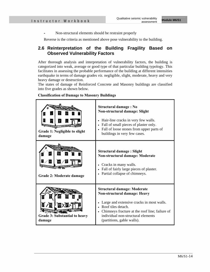
I n s t r u c t o r W o r k b o o k Qualitative seismic vulnerability
assessment Module M6/S1
M6/S1-14
- Non-structural elements should be restraint properly
Reverse is the criteria as mentioned above pose vulnerability to the building.
2.6 Reinterpretation of the Building Fragility Based on Observed Vulnerability Factors
After thorough analysis and interpretation of vulnerability factors, the building is categorized into weak, average or good type of that particular building typology. This facilitates in assessing the probable performance of the building at different intensities earthquake in terms of damage grades viz. negligible, slight, moderate, heavy and very heavy damage or destruction. The states of damage of Reinforced Concrete and Masonry buildings are classified into five grades as shown below.
Classification of Damage to Masonry Buildings
Grade 1: Negligible to slight damage
Structural damage : No Non-structural damage: Slight • Hair-line cracks in very few walls. • Fall of small pieces of plaster only. • Fall of loose stones from upper parts of
buildings in very few cases.
Grade 2: Moderate damage
Structural damage : Slight Non-structural damage: Moderate • Cracks in many walls. • Fall of fairly large pieces of plaster. • Partial collapse of chimneys.
Grade 3: Substantial to heavy damage
Structural damage: Moderate Non-structural damage: Heavy • Large and extensive cracks in most walls. • Roof tiles detach. • Chimneys fracture at the roof line; failure of
individual non-structural elements (partitions, gable walls).
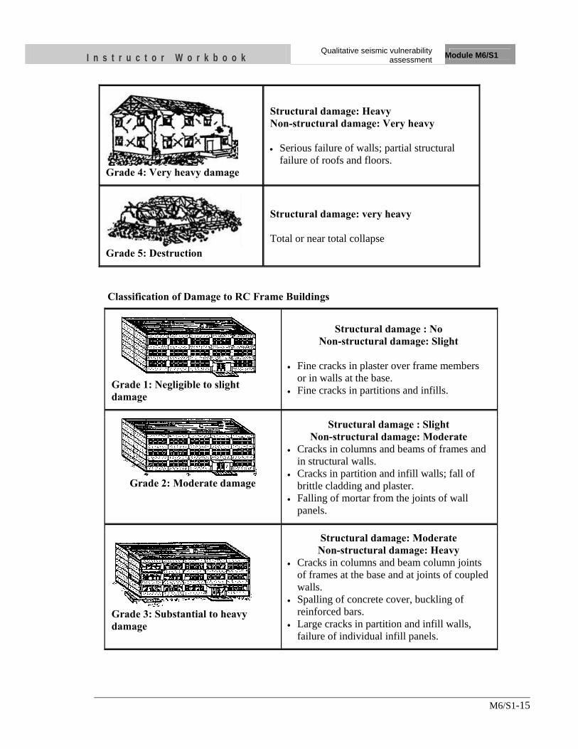
I n s t r u c t o r W o r k b o o k Qualitative seismic vulnerability
assessment Module M6/S1
M6/S1-15
Grade 4: Very heavy damage
Structural damage: Heavy Non-structural damage: Very heavy • Serious failure of walls; partial structural
failure of roofs and floors.
Grade 5: Destruction
Structural damage: very heavy Total or near total collapse
Classification of Damage to RC Frame Buildings
Grade 1: Negligible to slight damage
Structural damage : No Non-structural damage: Slight
• Fine cracks in plaster over frame members
or in walls at the base. • Fine cracks in partitions and infills.
Grade 2: Moderate damage
Structural damage : Slight Non-structural damage: Moderate
• Cracks in columns and beams of frames and in structural walls.
• Cracks in partition and infill walls; fall of brittle cladding and plaster.
• Falling of mortar from the joints of wall panels.
Grade 3: Substantial to heavy damage
Structural damage: Moderate Non-structural damage: Heavy
• Cracks in columns and beam column joints of frames at the base and at joints of coupled walls.
• Spalling of concrete cover, buckling of reinforced bars.
• Large cracks in partition and infill walls, failure of individual infill panels.
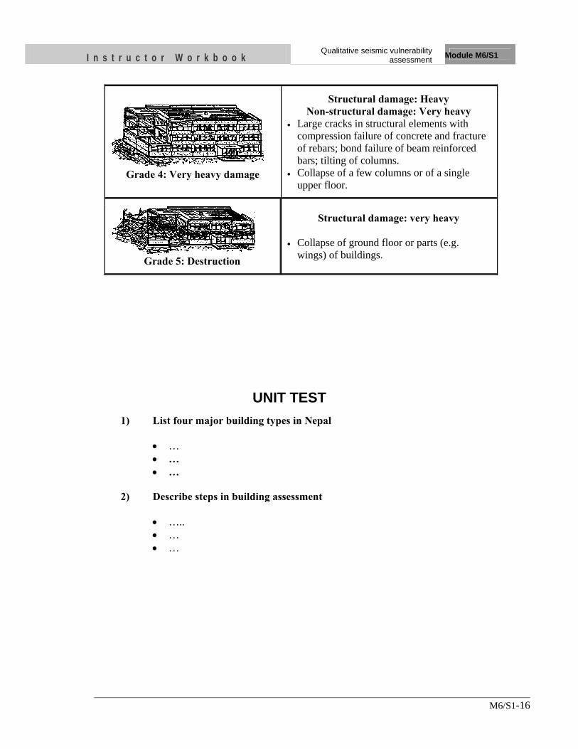
I n s t r u c t o r W o r k b o o k Qualitative seismic vulnerability
assessment Module M6/S1
M6/S1-16
Grade 4: Very heavy damage
Structural damage: Heavy Non-structural damage: Very heavy
• Large cracks in structural elements with compression failure of concrete and fracture of rebars; bond failure of beam reinforced bars; tilting of columns.
• Collapse of a few columns or of a single upper floor.
Grade 5: Destruction
Structural damage: very heavy • Collapse of ground floor or parts (e.g.
wings) of buildings.
UNIT TEST 1) List four major building types in Nepal
• … • … • …
2) Describe steps in building assessment
• ….. • … • …
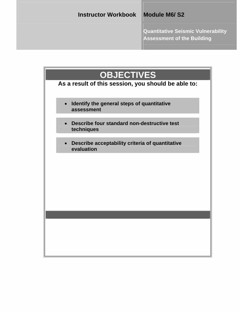
OBJECTIVES As a result of this session, you should be able to:
•• IIddeennttiiffyy tthhee ggeenneerraall sstteeppss ooff qquuaannttiittaattiivvee aasssseessssmmeenntt
• DDeessccrriibbee ffoouurr ssttaannddaarrdd nnoonn--ddeessttrruuccttiivvee tteesstt tteecchhnniiqquueess
• DDeessccrriibbee aacccceeppttaabbiilliittyy ccrriitteerriiaa ooff qquuaannttiittaattiivvee eevvaalluuaattiioonn
Instructor Workbook Module M6/ S2
Quantitative Seismic Vulnerability Assessment of the Building
CONTENTS
1. INTRODUCTION ...................................................................................................... 2
2. DECIDE PERFORMANCE OBJECTIVE .............................................................. 3
3. DESIGN BASIS EARTHQUAKE ............................................................................. 3
4. DETAIL INVESTIGATION / VERIFICATION OF STRUCTURAL DETAILS..................................................................................................................... 3
4.1 Assessing the Condition of the Building Components ....................................... 4
4.1.1 Deterioration of Concrete ...................................................................... 4
4.1.2 Cracks in Boundary Columns ................................................................ 4
4.1.3 Masonry Units ....................................................................................... 4
4.1.4 Masonry Joints ....................................................................................... 4
4.1.5 Cracks in Infill Walls ............................................................................. 5
4.2 Non-Destructive Tests ........................................................................................ 5
4.2.1 Sounding Test ........................................................................................ 5
4.2.2 Rebound Hammer Test .......................................................................... 6
4.2.3 Rebar Detection Test ............................................................................. 8
4.2.4 In-Situ Testing In-Place Shear ............................................................. 10
4.3 Supplemental Evaluation .................................................................................. 12
4.3.1 No Shear Failures ................................................................................. 12
4.3.2 Strong Column/Weak Beam ................................................................ 13
4.3.3 Beam Bars ............................................................................................ 13
4.3.4 Column-Bar Splices ............................................................................. 13
4.3.5 Beam- bar Splices ................................................................................ 14
4.3.6 Column-Tie Spacing ............................................................................ 15
4.3.7 Stirrup Spacing .................................................................................... 15
4.3.8 Joint Reinforcing.................................................................................. 16
4.3.9 Stirrup and Tie Hooks .......................................................................... 16
5. SEISMIC ANALYSIS AND DESIGN .................................................................... 16
5.1 Pushover Analysis ............................................................................................ 17
5.2 Acceptability Criteria ....................................................................................... 19
I n s t r u c t o r W o r k b o o k Quantitative seismic vulnerability
assessment Module M 6/S2
M6/S2-2
1. INTRODUCTION This session describes the quantitative approach of seismic vulnerability assessment which follows qualitative analysis. Before embarking on seismic retrofitting, seismic deficiencies shall have to be identified through a seismic evaluation process using a methodology described in “Qualitative Seismic Vulnerability Assessment”. The first phase assessment is general seismic vulnerability assessment method based on qualitative approach to identify the seismic deficiencies in the building. If the first phase study finds seismic deficiencies in the building and possible seismic performance is not up to the acceptable level/criteria, it recommends second phase or quantitative assessment. The second phase assessment involves a more detail seismic evaluation with complete analysis of the building for seismic strengthening measures as modifications to correct/ reduce seismic deficiencies identified during the evaluation procedure in first phase. Detail information about the building is required for this step of evaluation. Seismic retrofit becomes necessary if the building does not meet minimum requirements of the current Building Code, and may suffer severe damage or even collapse during a seismic event. Detailed evaluations need to be carried out for buildings with greater consequence in terms of loss of life. Minor buildings which have passed preliminary checks on seismic robustness are exempted from detailed evaluation, which requires considerable effort in collecting information and performing the analyses. However, detailed evaluations are mandatory for important buildings and those buildings with problematic soils/foundations and structural systems which require detailed investigation. The detailed evaluation procedure is based on determining the probable strength of lateral load resisting elements and comparing them with the expected seismic demands. An assessment of the building for its present condition of its components and strength of materials is required. The most important issue when beginning to evaluate the seismic capabilities of an existing building is the availabilities and reliability of structural drawings. Detail evaluation is impossible without framing and foundation plans, layout of preliminary lateral force elements, reinforcing for concrete structures, and connection detailing. Hence exploration and verification of the critical structural details and data is the most important part of this method of assessment. Seismic hazards other than ground shaking may also exist at the building site. The risk and possible extent of damage from such geologic site hazards should be considered before undertaking a seismic strengthening measure. In some cases it may be feasible to mitigate the site hazard or strengthen the building and still meet the performance level. In other cases the risk due to site hazard may be so extreme and difficult to control that seismic strengthening is neither cost-effective nor feasible. Quantitative assessment of an existing building shall be conducted in accordance with the process outlined in sections 2 through 5.
I n s t r u c t o r W o r k b o o k Quantitative seismic vulnerability
assessment Module M 6/S2
M6/S2-3
2. DECIDE PERFORMANCE OBJECTIVE The performance objective needs to be defined before analyzing the building for retrofit. The performance objective depends on various factors such as the use of building, cost and feasibility of any strengthening project, benefit to be obtained in terms of improved safety, reduction in property damage, interruption of use in the event of future earthquakes and moreover the limiting damage states. The minimum objective is Life Safety i.e. any part of the building should not collapse threatening safety of occupants during a severe earthquake. 3. DESIGN BASIS EARTHQUAKE Seismic hazard due to ground shaking shall be based on the location of the building with respect to causative faults, the regional and site-specific geologic characteristics, and a selected earthquake hazard level. Seismic hazard due to ground shaking shall be defined as acceleration response spectra or acceleration time histories on either a probabilistic or deterministic basis. Seismic strengthening of buildings shall comply with the design criteria and procedures as specified in national building codes and standards of earthquake engineering. A building must have been designed and constructed or evaluated in accordance with the current seismicity of the region. Total lateral force (design base shear) calculated as per the relevant code is multiplied by a factor for the reduced useable life equal to 0.67.
3.1 DETAIL INVESTIGATION / VERIFICATION OF STRUCTURAL DETAILS
The design professional shall review initial considerations which include structural characteristic of the building, seismic hazard including geological site hazards, results of prior seismic evaluations, areas of structural deficiencies, building use and occupancy requirements, historical status, economic considerations, societal issues, and local jurisdictional requirements. This step of evaluation should focus on the potential deficiencies identified in Qualitative Assessment. A site visit shall be conducted by the design professional to verify available existing building data or collect additional data, and to determine the condition of the building and its components. Strength capacities of existing building components should be based on the probable material strengths in the building. Probable or measured nominal strengths are best indicator of the actual strength and can only be obtained by field or lab tests. These can also be assessed from the values given in the original building documents. However, they all need to be further modified for the uncertainty regarding the reliability of available information, and present condition of the component.
I n s t r u c t o r W o r k b o o k Quantitative seismic vulnerability
assessment Module M 6/S2
M6/S2-4
3.2 Assessing the Condition of the Building Components
The building should be checked for the existence of some of the following common indicators of deficiency. A re-visit to the site should be made by the design professional to verify the existing data including those used in the preliminary analysis, and importantly to check the condition of various building components and perform suitable tests to assess the present day strength of materials for greater reliability. Deteriorated building components can jeopardize the capacity of a building to resist lateral forces.
3.2.1 Deterioration of Concrete
There should be no visible deterioration of the concrete or reinforcing steel in any of the vertical or lateral force resisting elements. When concrete is deteriorated the strength of concrete elements reduces significantly and along when water penetrates into concrete easily corrosion of reinforcing bars begins. This may lead to loss of cross-section of rebar and further strength loss. Concrete deterioration can also take the form of spalling which can lead to reduction in available surface area for bond between the concrete and steel.
3.2.2 Cracks in Boundary Columns
There shall be no existing diagonal cracks wider than 3 mm in concrete columns that encase masonry infills. Large displacements or crushing of concrete results in the formation of cracks and signify a reduction in the strength of structural components. Crack width is a commonly used indicator of damage level in components. Small cracks in components have little effect on strength but are matter of concern when they are large enough and not provide aggregate interlock or resistance against buckling of the reinforcement steel. Columns may be required to resist diagonal compression strut forces that are developed in infill wall panels, axial forces induced by vertical components and the moment due to eccentricity between horizontal components and the beam. Columns having cracks spread over a large area may indicate locations of possible weakness and such columns may not be able to function in conjunction with the infill panel as expected.
3.2.3 Masonry Units
There shall be no visible deterioration of masonry units.
3.2.4 Masonry Joints
The mortar shall not be easily scraped away from the joints by hand with a metal tool, and there shall be no areas of eroded mortar. The extent of loose or eroded
I n s t r u c t o r W o r k b o o k Quantitative seismic vulnerability
assessment Module M 6/S2
M6/S2-5
mortar shall be identified. Walls with loose mortar shall be omitted from the analysis, and the adequacy of the lateral-force-resisting system shall be evaluated. Alternatively, the adequacy of the walls may be evaluated with shear strength determined by testing.
3.2.5 Cracks in Infill Walls
There shall be no existing diagonal cracks in infill walls that extend throughout a panel, are greater than 3 mm, or have out-of-plane offsets in the bed joint greater than 3 mm. Diagonal wall cracks affect the interaction of the masonry units with surrounding frame and lead to a reduction in strength and stiffness. These cracks may also indicate distress in the wall from past seismic events, foundation settlement, or other causes. Offsets in the bed joint along the masonry joints may affect the interaction of the masonry units in resisting out-of-plane forces.
3.3 Non-Destructive Tests
For evaluation of member capacities, precise values of the material strength and the dimensions are desirable. An evaluation of the present day strength of materials can be performed using on-site non-destructive testing and laboratory analysis of samples taken from the building. Field tests are usually indicative tests and therefore should be supplemented with proper laboratory facilities for accurate quantitative results. Some standard test techniques are:
1) Sounding Test 2) Rebound Hammer Test 3) Rebar Detection Test 4) In-Situ Testing In-Place Shear
.
3.3.1 Sounding Test
Description Tapping on a wall with a dense object, such as a hammer, and listening to the vibrations emitted from the wall can be useful for identifying voids or delaminations in concrete and masonry walls. The sound produced from a solid wall will be different from that from a wall with voids or delaminations close to the surface. In concrete block masonry walls, sounding can be used to verify that the cells in the blocks have been grouted. Equipment The typical equipment required for sounding is a hammer. However, any hard, dense object can be used. Conducting Test In areas where the visual observations indicate that the wall may have delaminations, the wall can be sounded by tapping with a hammer. Delaminations and spalls will generally produce a hollow sound when compared with solid material. The wall
I n s t r u c t o r W o r k b o o k Quantitative seismic vulnerability
assessment Module M 6/S2
M6/S2-6
should be tapped several times in the suspect area and away from the suspect area, and the sounds compared. It is important to test an area that is undamaged, and of the same material and thickness to use as a baseline comparison. For a valid comparison, the force exerted by the tapping should be similar for both the suspect and baseline areas. In reinforced masonry construction, sounding can be used to assess whether the cells in the wall have been grouted. Near the ends of a block, the unit is solid for the full thickness of the wall. For most of the length of the block, it is relatively thin at the faces. If the sound near the end of the block is substantially different than at the middle of the cell, the cell is probably not grouted. Personal Qualification Sounding of concrete and masonry walls should be performed by an engineer or trained technician. Engineers and technicians should have previous experience in identifying damage to concrete and masonry structures. Engineers and technicians should also be able to distinguish between sounds emitted from a hammer strike. Prior experience is necessary for proper interpretation of results. Reporting Requirements The personnel conducting the tests should provide sketches of the wall indicating the location of the tests and the findings. The sketch should include the following information:
• Mark the location of the test on either a floor plan or wall elevation. • Report the results of the test, indicating the extent of delamination. • Report the date of the test. • List the responsible engineer overseeing the test and the name of the company conducting
the test.
Limitations The properties of the wall can influence the usefulness of sounding. The geometry of the wall and the thickness of the wall will affect the results. Sounding is best used away from the perimeter of the wall and on a wall of uniform thickness. The accuracy of information from sounding with a hammer also depends on the skill of the engineer or technician performing the test and on the depth of damage within the thickness of the wall. Delaminations up to the depth of the cover for the reinforcing bars (usually about 1 to 2 inches) can usually be detected. Detection of deeper spalls or delamination requires the use of other NDE techniques. Sounding cannot determine the depth of the spall or delamination. Tapping on a loose section of material can cause the piece to become dislodged and fall. Avoid sounding overhead. A ladder, scaffold, or other lift device should be used to reach higher elevations of a wall.
3.3.2 Rebound Hammer Test
Description A rebound hammer provides a method for assessing the in-situ compressive strength of concrete. In this test, a calibrated hammer impact is applied to the surface of the concrete. The amount of rebound of the hammer is measured and correlated with the

I n s t r u c t o r W o r k b o o k Quantitative seismic vulnerability
assessment Module M 6/S2
M6/S2-7
manufacturer's data to estimate the strength of the concrete. The method has also been used to evaluate the strength of masonry. Equipment A calibrated rebound hammer is a single piece of equipment that is hand operated Execution The person operating the equipment places the impact plunger of the hammer against the concrete and then presses the hammer until the hammer releases. The operator then records the value on the scale of the hammer. Typically three or more tests are conducted at a location. If the values from the tests are consistent, record the average value. If the values vary significantly, additional readings should be taken until a consistent pattern of results is obtained. Since the test is relatively rapid, a number of test locations can be chosen for each wall. The values from the tests are converted into compressive strength using tables prepared by the manufacturer of the rebound hammer.
Use of Rebound Hammer Rebound Hammer
Personal Qualification A technician with minimal training can operate the rebound hammer. An engineer experienced with rebound hammer data should be available to supervise to verify that any anomalous values can be explained. Reporting Requirements The personnel conducting the tests should provide sketches of the wall, indicating the location of the tests and the findings. The sketch should include the following information:
• Mark the location of the test marked on either a floor plan or wall elevation. • Record the number of tests conducted at a given location. • Report either the average of actual readings or the average values converted into
compressive strength along with the method used to convert the values into compressive strength.
• Report the type of rebound hammer used along with the date of last calibration. • Record the date of the test. • List the responsible engineer overseeing the test and the name of the company
conducting the test.
I n s t r u c t o r W o r k b o o k Quantitative seismic vulnerability
assessment Module M 6/S2
M6/S2-8
Limitations The rebound hammer does not give a precise value of compressive strength, but rather an estimate of strength that can be used for comparison. Frequent calibration of the unit is required (ACI, 1994). Although manufacturers’ tables can be used to estimate the concrete strength, better estimates can be obtained by removing core samples at selected locations where the rebound testing has been performed. The core samples are then subjected to compression tests. The rebound values from other areas can be compared with the rebound values that correspond to the measured core compressive strength. The results of the rebound hammer tests are sensitive to the quality of the concrete on the outer several inches of the wall. More reproducible results can be obtained from formed surfaces rather than from finished surfaces. Surface moisture and roughness can also affect the readings. The impact from the rebound hammer can produce a slight dimple in the surface of the wall. Do not take more than one reading at the same spot, since the first impact can affect the surface, and thus affect the results of a subsequent test. When using the rebound hammer on masonry, the hammer should be placed at the centre of the masonry unit. The values of the tests on masonry reflect the strength of the masonry unit and the mortar. This method is only useful in assessing the strength of the outer wythe of a multi-wythe wall.
3.3.3 Rebar Detection Test
Description Cover meter is the general term for a rebar detector used to determine the location and size of reinforcing steel in a concrete or masonry wall. The basic principle of most rebar detectors is the interaction between the reinforcing bar and a low frequency magnetic field. If used properly, many types of rebar detectors can also identify the amount of cover for the bar and/or the size of the bar. Rebar detection is useful for verifying the construction of the wall, if drawings are available, and in preparing as-built data if no previous construction information is available. Equipment Several types and brands of rebar detectors are commercially available. The two general classes are those based on the principle of magnetic reluctance and those based on the principle of eddy. The various models can have a variety of features including analogue or digital readout, audible signal, one-handed operation, and readings for reinforcing bars and prestressing tendons. Some models can store the data on floppy disks to be imported into computer programs for plotting results. Conducting Test The unit is held away from metallic objects and calibrated to zero reading. After calibration, the unit is placed against the surface of the wall. The orientation of the probe should be in the direction of the rebar that is being detected. The probe is slid slowly along the wall, perpendicular to the orientation of the probe, until an audible or visual spike in the readout is encountered. The probe is passed back and forth over the region of the spike to find the location of the maximum reading, which should correspond to the location of the rebar. This location is then marked on the wall. The procedure is repeated for the perpendicular direction of reinforcing.
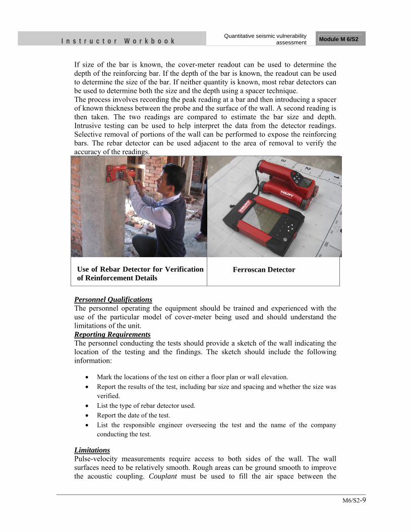
I n s t r u c t o r W o r k b o o k Quantitative seismic vulnerability
assessment Module M 6/S2
M6/S2-9
If size of the bar is known, the cover-meter readout can be used to determine the depth of the reinforcing bar. If the depth of the bar is known, the readout can be used to determine the size of the bar. If neither quantity is known, most rebar detectors can be used to determine both the size and the depth using a spacer technique. The process involves recording the peak reading at a bar and then introducing a spacer of known thickness between the probe and the surface of the wall. A second reading is then taken. The two readings are compared to estimate the bar size and depth. Intrusive testing can be used to help interpret the data from the detector readings. Selective removal of portions of the wall can be performed to expose the reinforcing bars. The rebar detector can be used adjacent to the area of removal to verify the accuracy of the readings.
Use of Rebar Detector for Verification of Reinforcement Details
Ferroscan Detector
Personnel Qualifications The personnel operating the equipment should be trained and experienced with the use of the particular model of cover-meter being used and should understand the limitations of the unit. Reporting Requirements The personnel conducting the tests should provide a sketch of the wall indicating the location of the testing and the findings. The sketch should include the following information:
• Mark the locations of the test on either a floor plan or wall elevation. • Report the results of the test, including bar size and spacing and whether the size was
verified. • List the type of rebar detector used. • Report the date of the test. • List the responsible engineer overseeing the test and the name of the company
conducting the test.
Limitations Pulse-velocity measurements require access to both sides of the wall. The wall surfaces need to be relatively smooth. Rough areas can be ground smooth to improve the acoustic coupling. Couplant must be used to fill the air space between the
I n s t r u c t o r W o r k b o o k Quantitative seismic vulnerability
assessment Module M 6/S2
M6/S2-10
transducer and the surface of the wall. If air voids exist between the transducer and the surface, the travel time of the pulse will increase, causing incorrect readings. Some couplant materials can stain the wall surface. Non-staining gels are available, but should be checked in an inconspicuous area to verify that it will not disturb the appearance. Embedded reinforcing bars, oriented in the direction of travel of the pulse, can affect the results, since the ultrasonic pulses travel through steel at a faster rate than will significantly affect the results. The moisture content of the concrete also has a slight effect (up to about 2 percent) on the pulse velocity. Pulse-velocity measurements can detect the presence of voids or discontinuities within a wall; however, these measurements cannot determine the depth of the voids.
3.3.4 In-Situ Testing In-Place Shear
Description The shear strength of unreinforced masonry construction depends largely on the strength of the mortar used in the wall. An in-place shear test is the preferred method for determining the strength of existing mortar. The results of these tests are used to determine the shear strength of the wall. Equipment
• Chisels and grinders are needed to remove the bricks and mortar adjacent to the test area.
• A hydraulic ram, calibrated and capable of displaying the applied load. • A dial gauge, calibrated to 0.001 inch.
Execution Prepare the test location by removing the brick, including the mortar, on one side of the brick to be tested. The head joint on the opposite side of the brick to be tested is also removed. Care must be exercised so that the mortar joint above or below the brick to be tested is not damaged. The hydraulic ram is inserted in the space where the brick was removed. A steel loading block is placed between the ram and the brick to be tested so that the ram will distribute its load over the end face of the brick. The dial gauge can also be inserted in the space. The brick is then loaded with the ram until the first indication of cracking or movement of the brick. The ram force and associated deflection on the dial gage are recorded to develop a force-deflection plot on which the first cracking or movement should be indicated. A dial gauge can be used to calculate a rough estimate of shear stiffness. Inspect the collar joint and estimate the percentage of the collar joint that was effective in resisting the force from the ram. The brick that was removed should then be replaced and the joints re-pointed.
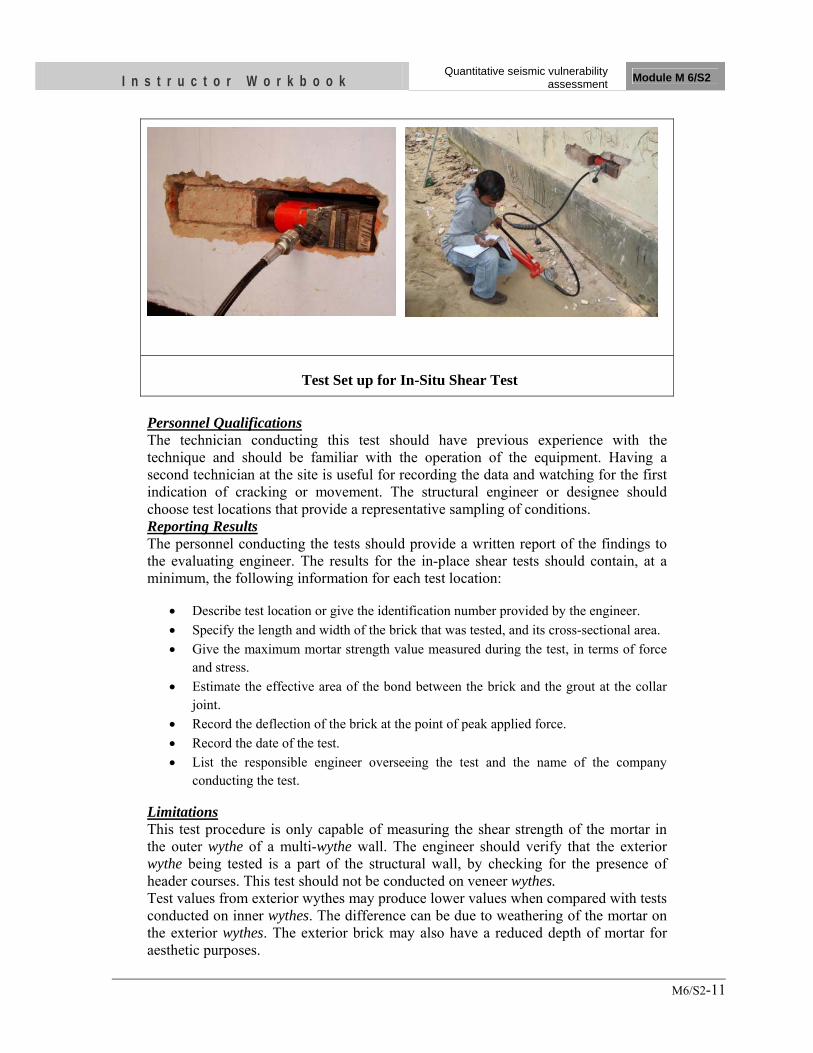
I n s t r u c t o r W o r k b o o k Quantitative seismic vulnerability
assessment Module M 6/S2
M6/S2-11
Test Set up for In-Situ Shear Test
Personnel Qualifications The technician conducting this test should have previous experience with the technique and should be familiar with the operation of the equipment. Having a second technician at the site is useful for recording the data and watching for the first indication of cracking or movement. The structural engineer or designee should choose test locations that provide a representative sampling of conditions. Reporting Results The personnel conducting the tests should provide a written report of the findings to the evaluating engineer. The results for the in-place shear tests should contain, at a minimum, the following information for each test location:
• Describe test location or give the identification number provided by the engineer. • Specify the length and width of the brick that was tested, and its cross-sectional area. • Give the maximum mortar strength value measured during the test, in terms of force
and stress. • Estimate the effective area of the bond between the brick and the grout at the collar
joint. • Record the deflection of the brick at the point of peak applied force. • Record the date of the test. • List the responsible engineer overseeing the test and the name of the company
conducting the test.
Limitations This test procedure is only capable of measuring the shear strength of the mortar in the outer wythe of a multi-wythe wall. The engineer should verify that the exterior wythe being tested is a part of the structural wall, by checking for the presence of header courses. This test should not be conducted on veneer wythes. Test values from exterior wythes may produce lower values when compared with tests conducted on inner wythes. The difference can be due to weathering of the mortar on the exterior wythes. The exterior brick may also have a reduced depth of mortar for aesthetic purposes.
I n s t r u c t o r W o r k b o o k Quantitative seismic vulnerability
assessment Module M 6/S2
M6/S2-12
The test results can only be qualitatively adjusted to account for the presence of mortar in the collar joints. If mortar is present in the collar joint, the engineer or technician conducting the test is not able to discern how much of that mortar actually resisted the force from the ram. The personnel conducting the tests must carefully watch the brick during the test to accurately determine the ram force at which first cracking or movement occurs. First cracking or movement indicates the maximum force, and thus the maximum shear strength. If this peak is missed, the values obtained will be based only on the sliding friction contribution of the mortar, which will be less than the bond strength contribution.
3.4 Supplemental Evaluation
In addition to the general evaluation for buildings which addresses only strength issues more criteria need to be considered which relate to ductility and detailing of structural components. These criteria address certain special features affecting the lateral load-behavior which are specific to each building type. For RC moment frame buildings designed using response reduction factor R (IS 1893 (Part 1)) equal to 5 the following supplemental criteria need to be satisfied.
3.4.1 No Shear Failures
Shear capacity of frame members shall be adequate to develop the moment capacity at the ends, and shall be in accordance with provisions of IS: 13920 for shear design of beams and columns. Shear failure is a brittle failure whereas flexural failure is ductile. When the column attains shear capacity before its moment capacity, it develops a non-ductile sudden failure, leading to collapse. Columns should therefore be designed in such a fashion to not reach their shear capacity before reaching its flexural capacity. The shear capacity of a column is affected by axial loads acting on it, so its shear capacity should be based on the most critical combination of axial load and shear. The design shear force for columns shall be the maximum of: a) calculated factored shear force as per analysis, b)a factored shear force given by
Where, Mblu,lim and MbRu,lim are moment of resistance, of opposite signs, of beams framing into the column from opposite faces and hst is the storey height. The beam moment capacity is to be calculated as per IS 456: 2000. The factor of 1.4 is based on the consideration that plastic moment capacity of a section is usually calculated by assuming the stress in flexural reinforcement as 1.25 fy as against 0.87 fy in the moment capacity calculation.
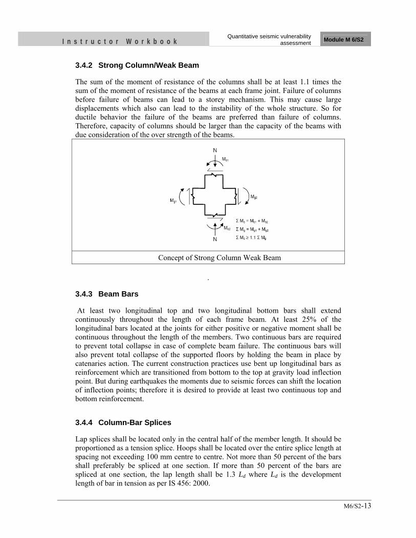
I n s t r u c t o r W o r k b o o k Quantitative seismic vulnerability
assessment Module M 6/S2
M6/S2-13
3.4.2 Strong Column/Weak Beam
The sum of the moment of resistance of the columns shall be at least 1.1 times the sum of the moment of resistance of the beams at each frame joint. Failure of columns before failure of beams can lead to a storey mechanism. This may cause large displacements which also can lead to the instability of the whole structure. So for ductile behavior the failure of the beams are preferred than failure of columns. Therefore, capacity of columns should be larger than the capacity of the beams with due consideration of the over strength of the beams.
Concept of Strong Column Weak Beam
.
3.4.3 Beam Bars
At least two longitudinal top and two longitudinal bottom bars shall extend continuously throughout the length of each frame beam. At least 25% of the longitudinal bars located at the joints for either positive or negative moment shall be continuous throughout the length of the members. Two continuous bars are required to prevent total collapse in case of complete beam failure. The continuous bars will also prevent total collapse of the supported floors by holding the beam in place by catenaries action. The current construction practices use bent up longitudinal bars as reinforcement which are transitioned from bottom to the top at gravity load inflection point. But during earthquakes the moments due to seismic forces can shift the location of inflection points; therefore it is desired to provide at least two continuous top and bottom reinforcement.
3.4.4 Column-Bar Splices
Lap splices shall be located only in the central half of the member length. It should be proportioned as a tension splice. Hoops shall be located over the entire splice length at spacing not exceeding 100 mm centre to centre. Not more than 50 percent of the bars shall preferably be spliced at one section. If more than 50 percent of the bars are spliced at one section, the lap length shall be 1.3 Ld where Ld is the development length of bar in tension as per IS 456: 2000.
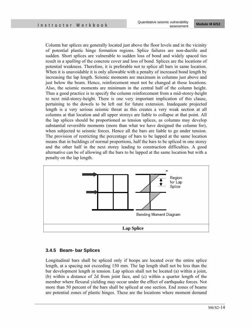
I n s t r u c t o r W o r k b o o k Quantitative seismic vulnerability
assessment Module M 6/S2
M6/S2-14
Column bar splices are generally located just above the floor levels and in the vicinity of potential plastic hinge formation regions. Splice failures are non-ductile and sudden. Short splices are vulnerable to sudden loss of bond and widely spaced ties result in a spalling of the concrete cover and loss of bond. Splices are the locations of potential weakness. Therefore, it is preferable not to splice all bars in same location. When it is unavoidable it is only allowable with a penalty of increased bond length by increasing the lap length. Seismic moments are maximum in columns just above and just below the beam. Hence, reinforcement must not be changed at those locations. Also, the seismic moments are minimum in the central half of the column height. Thus a good practice is to specify the column reinforcement from a mid-storey-height to next mid-storey-height. There is one very important implication of this clause, pertaining to the dowels to be left out for future extension. Inadequate projected length is a very serious seismic threat as this creates a very weak section at all columns at that location and all upper storeys are liable to collapse at that point. All the lap splices should be proportioned as tension splices, as columns may develop substantial reversible moments (more than what we have designed the column for), when subjected to seismic forces. Hence all the bars are liable to go under tension. The provision of restricting the percentage of bars to be lapped at the same location means that in buildings of normal proportions, half the bars to be spliced in one storey and the other half in the next storey leading to construction difficulties. A good alternative can be of allowing all the bars to be lapped at the same location but with a penalty on the lap length.
Lap Splice
3.4.5 Beam- bar Splices
Longitudinal bars shall be spliced only if hoops are located over the entire splice length, at a spacing not exceeding 150 mm. The lap length shall not be less than the bar development length in tension. Lap splices shall not be located (a) within a joint, (b) within a distance of 2d from joint face, and (c) within a quarter length of the member where flexural yielding may occur under the effect of earthquake forces. Not more than 50 percent of the bars shall be spliced at one section. End zones of beams are potential zones of plastic hinges. These are the locations where moment demand
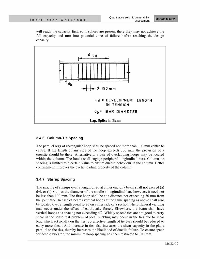
I n s t r u c t o r W o r k b o o k Quantitative seismic vulnerability
assessment Module M 6/S2
M6/S2-15
will reach the capacity first, so if splices are present there they may not achieve the full capacity and turn into potential zone of failure before reaching the design capacity.
Lap, Splice in Beam
3.4.6 Column-Tie Spacing
The parallel legs of rectangular hoop shall be spaced not more than 300 mm centre to centre. If the length of any side of the hoop exceeds 300 mm, the provision of a crosstie should be there. Alternatively, a pair of overlapping hoops may be located within the column. The hooks shall engage peripheral longitudinal bars. Column tie spacing is limited to a certain value to ensure ductile behaviour in the column. Better confinement improves the cyclic loading property of the column.
3.4.7 Stirrup Spacing
The spacing of stirrups over a length of 2d at either end of a beam shall not exceed (a) d/4, or (b) 8 times the diameter of the smallest longitudinal bar; however, it need not be less than 100 mm. The first hoop shall be at a distance not exceeding 50 mm from the joint face. In case of beams vertical hoops at the same spacing as above shall also be located over a length equal to 2d on either side of a section where flexural yielding may occur under the effect of earthquake forces. Elsewhere, the beam shall have vertical hoops at a spacing not exceeding d/2. Widely spaced ties are not good to carry shear in the sense that problem of local buckling may occur in the ties due to shear load which act axially on the ties. So effective length of tie bars should be reduced to carry more shear. And increase in ties also increases the shear capacity in the plane parallel to the ties, thereby increases the likelihood of ductile failure. To ensure space for needle vibrator, the minimum hoop spacing has been restricted to 100 mm.
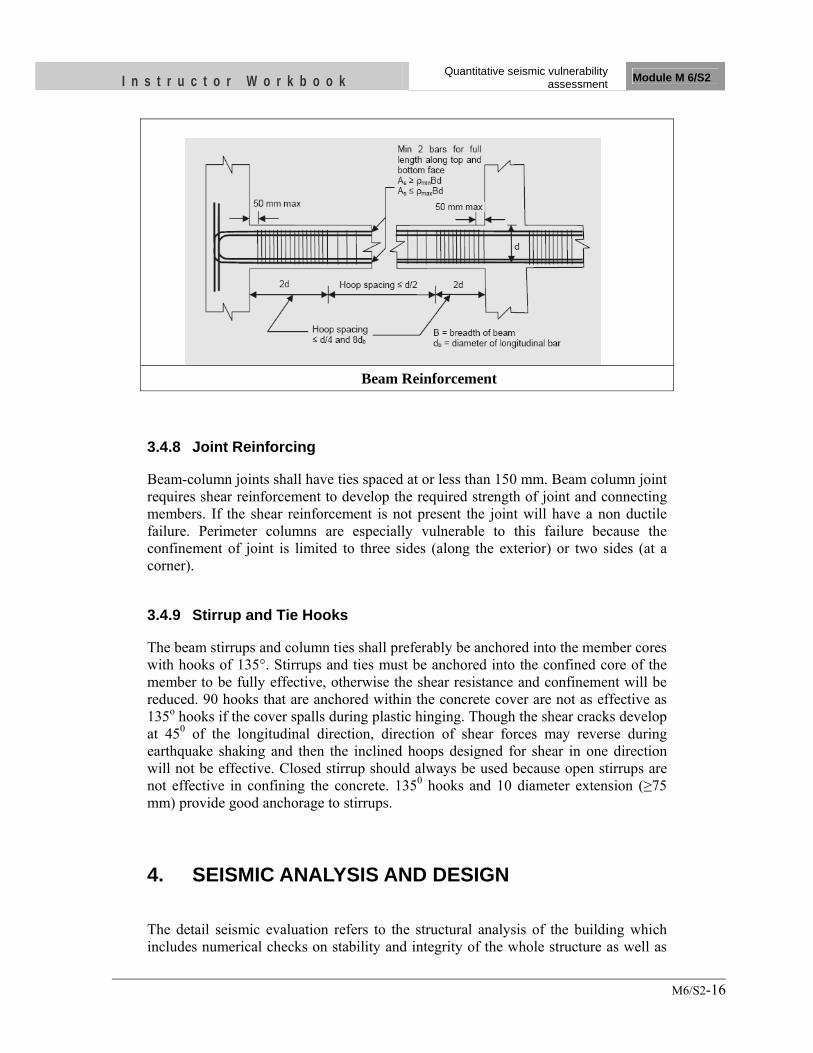
I n s t r u c t o r W o r k b o o k Quantitative seismic vulnerability
assessment Module M 6/S2
M6/S2-16
Beam Reinforcement
3.4.8 Joint Reinforcing
Beam-column joints shall have ties spaced at or less than 150 mm. Beam column joint requires shear reinforcement to develop the required strength of joint and connecting members. If the shear reinforcement is not present the joint will have a non ductile failure. Perimeter columns are especially vulnerable to this failure because the confinement of joint is limited to three sides (along the exterior) or two sides (at a corner).
3.4.9 Stirrup and Tie Hooks
The beam stirrups and column ties shall preferably be anchored into the member cores with hooks of 135°. Stirrups and ties must be anchored into the confined core of the member to be fully effective, otherwise the shear resistance and confinement will be reduced. 90 hooks that are anchored within the concrete cover are not as effective as 135o hooks if the cover spalls during plastic hinging. Though the shear cracks develop at 450 of the longitudinal direction, direction of shear forces may reverse during earthquake shaking and then the inclined hoops designed for shear in one direction will not be effective. Closed stirrup should always be used because open stirrups are not effective in confining the concrete. 1350 hooks and 10 diameter extension (≥75 mm) provide good anchorage to stirrups. 4. SEISMIC ANALYSIS AND DESIGN The detail seismic evaluation refers to the structural analysis of the building which includes numerical checks on stability and integrity of the whole structure as well as
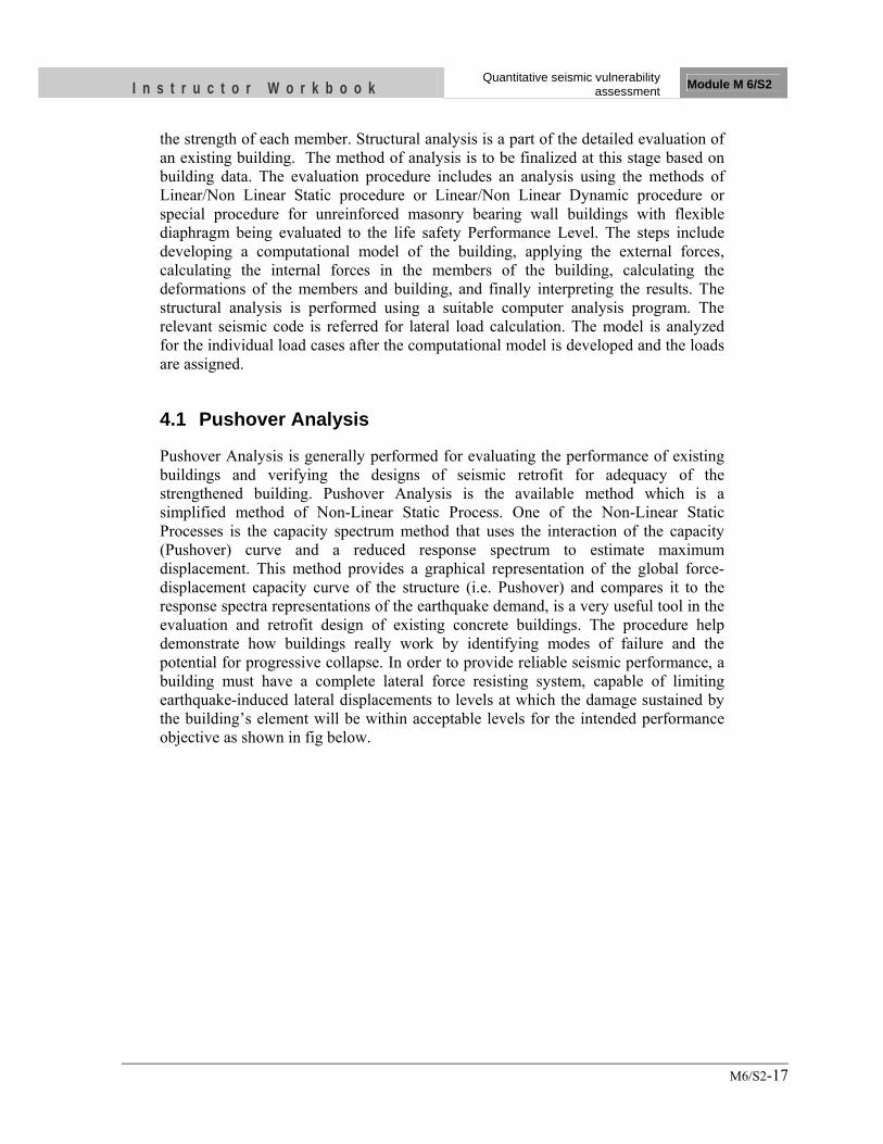
I n s t r u c t o r W o r k b o o k Quantitative seismic vulnerability
assessment Module M 6/S2
M6/S2-17
the strength of each member. Structural analysis is a part of the detailed evaluation of an existing building. The method of analysis is to be finalized at this stage based on building data. The evaluation procedure includes an analysis using the methods of Linear/Non Linear Static procedure or Linear/Non Linear Dynamic procedure or special procedure for unreinforced masonry bearing wall buildings with flexible diaphragm being evaluated to the life safety Performance Level. The steps include developing a computational model of the building, applying the external forces, calculating the internal forces in the members of the building, calculating the deformations of the members and building, and finally interpreting the results. The structural analysis is performed using a suitable computer analysis program. The relevant seismic code is referred for lateral load calculation. The model is analyzed for the individual load cases after the computational model is developed and the loads are assigned.
4.1 Pushover Analysis
Pushover Analysis is generally performed for evaluating the performance of existing buildings and verifying the designs of seismic retrofit for adequacy of the strengthened building. Pushover Analysis is the available method which is a simplified method of Non-Linear Static Process. One of the Non-Linear Static Processes is the capacity spectrum method that uses the interaction of the capacity (Pushover) curve and a reduced response spectrum to estimate maximum displacement. This method provides a graphical representation of the global force-displacement capacity curve of the structure (i.e. Pushover) and compares it to the response spectra representations of the earthquake demand, is a very useful tool in the evaluation and retrofit design of existing concrete buildings. The procedure help demonstrate how buildings really work by identifying modes of failure and the potential for progressive collapse. In order to provide reliable seismic performance, a building must have a complete lateral force resisting system, capable of limiting earthquake-induced lateral displacements to levels at which the damage sustained by the building’s element will be within acceptable levels for the intended performance objective as shown in fig below.
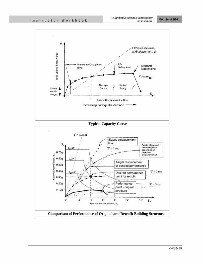
I n s t r u c t o r W o r k b o o k Quantitative seismic vulnerability
assessment Module M 6/S2
M6/S2-18
Typical Capacity Curve
Comparison of Performance of Original and Retrofit Building Structure
I n s t r u c t o r W o r k b o o k Quantitative seismic vulnerability
assessment Module M 6/S2
M6/S2-19
4.2 Acceptability Criteria
A building is said to be acceptable if either of the following two conditions are satisfied along with supplemental criteria for a particular building type described in section 4.3: a) All critical elements of lateral force resisting elements have strengths greater than computed actions and drift checks are satisfied. b) Except a few elements, all critical elements of the lateral force resisting elements have strengths greater than computed actions and drift checks are satisfied. The engineer has to ensure that the failure of these few elements will not lead to loss of stability or initiate progressive collapse. This needs to be verified by a non-linear analysis such as pushover analysis, carried out up to the collapse load.
I n s t r u c t o r W o r k b o o k Quantitative seismic vulnerability
assessment Module M 6/S2
M6/S2-20
UNIT TEST 1) Describe the general steps of quantitative evaluation
• ….
2) List four standard non-destructive test techniques
• … • … • … • ...
3) What general condition of the building is checked for evaluation
• .....
OBJECTIVES
As a result of this session, you should be able to:
• Define seismic retrofitting
• Identify five different methods of strengthening of masonry buildings
• Identify three different methods of strengthening of RC frame buildings
Instructor Workbook Module M6/S3
Structural Mitigation
Engineers’ Training on Earthquake-Resistant Design of Buildings
CONTENTS
1 Introduction ...................................................................................................... 1
1.1 Philosophy and Approach of Seismic Strengthening ............................... 1
2 Retrofitting Techniques of Masonry Buildings ............................................. 2
2.1 Major Weaknesses Revealed During Earthquakes in Similar Building Typology ................................................................................................... 3
2.2 Common Retrofitting Methods for the Masonry Buildings ...................... 3
2.2.1 Jacketing ........................................................................................ 4
2.2.2 Splint and Bandage ....................................................................... 5
2.2.3 Bolting/ Pre-stressing .................................................................... 5
2.2.4 Confinement with Reinforced Concrete Elements ........................ 6
2.2.5 Wall Bracing ................................................................................. 6
3 Retrofitting Techniques of RC Frame Buildings .......................................... 7
3.1 Major Weaknesses Revealed During Earthquakes in Similar Building Typology ................................................................................................... 7
3.2 Common Retrofitting Methods for the Reinforced Concrete Buildings ... 8
3.2.1 Jacketing ........................................................................................ 9
3.2.2 Addition of Reinforced Concrete Shear Walls ............................ 12
3.2.3 Steel Bracing ............................................................................... 12
M6/S3-1
I n s t r u c t o r W o r k b o o k Structural Mitigation Module M6/S3
1 INTRODUCTION
Seismic strengthening or retrofitting refers to technical interventions in the structural system of a building that improves its seismic resistance by increasing strength and ductility. The decision to strengthen the building depends on the buildings seismic resistance. If the probable performance of the building is not up to the acceptable limit of minimum Life Safety, retrofitting or seismic strengthening is desired. Seismic strengthening also reduces the post earthquake repair and re-strengthening cost.
This session identifies possible intervention options for improved seismic protection of masonry and RC Frame buildings and its occupants. The intervention options are based on past experience on similar building typology. A detailed technical design would be done before implementation of retrofitting work.
Different options for intervention are considered. Intervention in an existing building to improve their seismic resistance involves four main issues: First is the engineering method employed and considerations of technicalities of code requirements, design approach, and materials and construction techniques. Second is the cost of the program, such as cost of design and testing, construction, and the cost of permits and approvals. Third is the indirect cost of retrofitting such as relocation cost. Fourth is the question of the effectiveness of the strengthening in reducing the likely damage.
The fourth issue raises the acceptability of a certain level of risk. With increasing level of intervention for retrofitting the safety would increase but at the same time capital cost will also increase which might make the option unfeasible.
1.1 Philosophy and Approach of Seismic Strengthening
Various alternatives have been developed for retrofitting of the buildings. These alternatives would provide different level of seismic safety and will require different level of intervention and obviously the capital investment. Philosophy adopted for development of retrofitting alternatives is:
i) Meet Codal provisions if possible, ii) achieving delayed collapse allowing occupants to escape during an earthquake for traditional buildings where it is not possible to bring them up to the Codal requirements, and iii) achieving reduction in the likely damage allowing post-earthquake repair and re-strengthening at nominal costs. Additional requirements as follows are also considered:
• Compatibility of the solution with the functional requirements of the structure
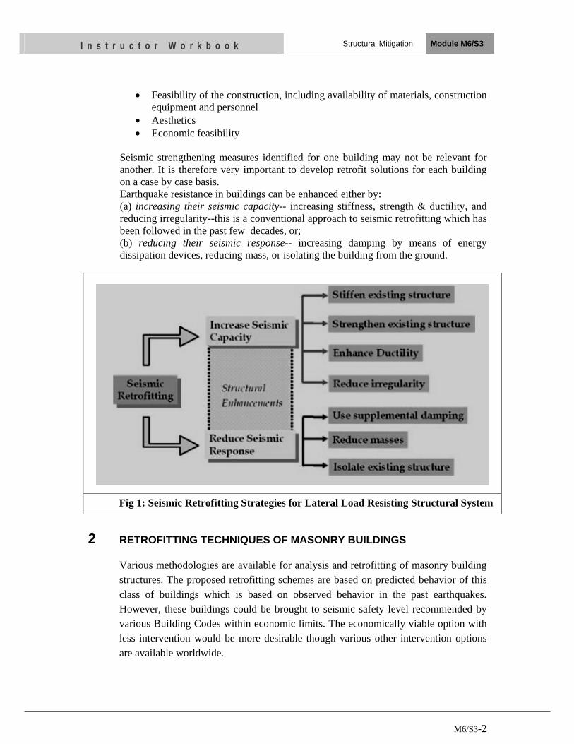
M6/S3-2
I n s t r u c t o r W o r k b o o k Structural Mitigation Module M6/S3
• Feasibility of the construction, including availability of materials, construction equipment and personnel
• Aesthetics • Economic feasibility
Seismic strengthening measures identified for one building may not be relevant for another. It is therefore very important to develop retrofit solutions for each building on a case by case basis. Earthquake resistance in buildings can be enhanced either by: (a) increasing their seismic capacity-- increasing stiffness, strength & ductility, and reducing irregularity--this is a conventional approach to seismic retrofitting which has been followed in the past few decades, or; (b) reducing their seismic response-- increasing damping by means of energy dissipation devices, reducing mass, or isolating the building from the ground.
Fig 1: Seismic Retrofitting Strategies for Lateral Load Resisting Structural System
2 RETROFITTING TECHNIQUES OF MASONRY BUILDINGS
Various methodologies are available for analysis and retrofitting of masonry building structures. The proposed retrofitting schemes are based on predicted behavior of this class of buildings which is based on observed behavior in the past earthquakes. However, these buildings could be brought to seismic safety level recommended by various Building Codes within economic limits. The economically viable option with less intervention would be more desirable though various other intervention options are available worldwide.
M6/S3-3
I n s t r u c t o r W o r k b o o k Structural Mitigation Module M6/S3
Out of the various available methods, the following alternatives have been identified as practically feasible and economically viable methods in our context for retrofitting of buildings.
2.1 Major Weaknesses Revealed During Earthquakes in Similar Building Typology
The following are the major types of problems and basic damage patterns during earthquakes in this type of buildings:
• Non-integrity of wall, floor and roof structures and their components
• Out-of-plane collapse due to lack of anchoring elements on upper parts of the wall of the flexible roof buildings
• Separate orthogonal walls at junctions due to developing cracks
• Collapse of gable wall since it behaves as a free cantilever
• Reduce wall stiffness or storey stiffness due to large opening
• Out-of plane failure of walls due to lack of cross walls
• Collapse of the building due to rapid cracking and disintegrating of various parts due to brittle nature
2.2 Common Retrofitting Methods for the Masonry Buildings
The concept of retrofitting masonry buildings start from enhancing integrity to the structure by providing proper connections between its resisting elements in such a way that inertia forces generated by the vibration of the building can be transmitted to the members that have ability to resist. Typical important aspects are the connection a) between components of floors and roof; b) between roof or floors and walls; c) between intersecting walls; and d) walls and foundation.
Commonly used improvement methods include eliminating features that are a) sources of weakness or which produce concentrations of stresses in some members, b) abrupt change of stiffness from floor to floor, c) concentration of large masses, and d) large openings in walls without proper peripheral reinforcement. Increasing the lateral strength in one or both directions, by reinforcing or by increasing wall plan areas or the number of walls may be required in some cases.
Avoiding the possibility of brittle mode of failure by providing proper reinforcement and connection of load resisting members is the overall objective.
Selected retrofitting options for the masonry buildings, considering the basic principles of retrofitting mentioned above, are described below:
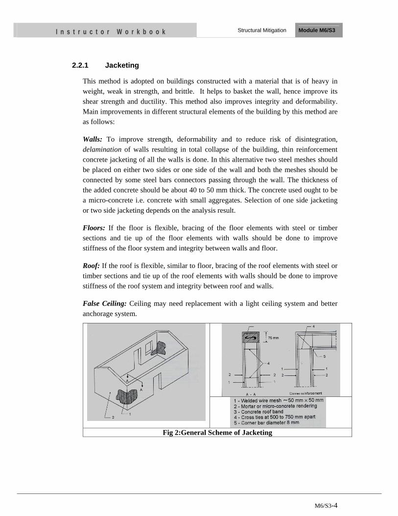
M6/S3-4
I n s t r u c t o r W o r k b o o k Structural Mitigation Module M6/S3
2.2.1 Jacketing
This method is adopted on buildings constructed with a material that is of heavy in weight, weak in strength, and brittle. It helps to basket the wall, hence improve its shear strength and ductility. This method also improves integrity and deformability. Main improvements in different structural elements of the building by this method are as follows:
Walls: To improve strength, deformability and to reduce risk of disintegration, delamination of walls resulting in total collapse of the building, thin reinforcement concrete jacketing of all the walls is done. In this alternative two steel meshes should be placed on either two sides or one side of the wall and both the meshes should be connected by some steel bars connectors passing through the wall. The thickness of the added concrete should be about 40 to 50 mm thick. The concrete used ought to be a micro-concrete i.e. concrete with small aggregates. Selection of one side jacketing or two side jacketing depends on the analysis result.
Floors: If the floor is flexible, bracing of the floor elements with steel or timber sections and tie up of the floor elements with walls should be done to improve stiffness of the floor system and integrity between walls and floor.
Roof: If the roof is flexible, similar to floor, bracing of the roof elements with steel or timber sections and tie up of the roof elements with walls should be done to improve stiffness of the roof system and integrity between roof and walls.
False Ceiling: Ceiling may need replacement with a light ceiling system and better anchorage system.
Fig 2:General Scheme of Jacketing
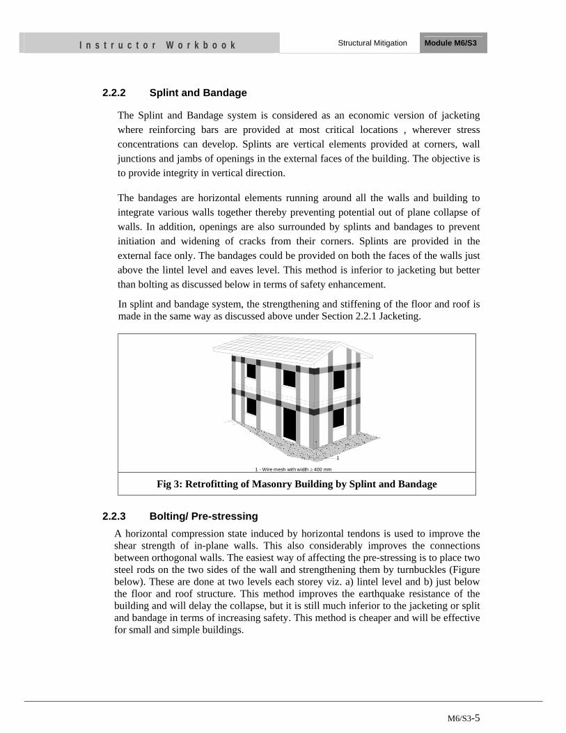
M6/S3-5
I n s t r u c t o r W o r k b o o k Structural Mitigation Module M6/S3
2.2.2 Splint and Bandage
The Splint and Bandage system is considered as an economic version of jacketing where reinforcing bars are provided at most critical locations , wherever stress concentrations can develop. Splints are vertical elements provided at corners, wall junctions and jambs of openings in the external faces of the building. The objective is to provide integrity in vertical direction.
The bandages are horizontal elements running around all the walls and building to integrate various walls together thereby preventing potential out of plane collapse of walls. In addition, openings are also surrounded by splints and bandages to prevent initiation and widening of cracks from their corners. Splints are provided in the external face only. The bandages could be provided on both the faces of the walls just above the lintel level and eaves level. This method is inferior to jacketing but better than bolting as discussed below in terms of safety enhancement.
In splint and bandage system, the strengthening and stiffening of the floor and roof is made in the same way as discussed above under Section 2.2.1 Jacketing.
1 - Wire mesh with width 400 mm≥
1
Fig 3: Retrofitting of Masonry Building by Splint and Bandage
2.2.3 Bolting/ Pre-stressing
A horizontal compression state induced by horizontal tendons is used to improve the shear strength of in-plane walls. This also considerably improves the connections between orthogonal walls. The easiest way of affecting the pre-stressing is to place two steel rods on the two sides of the wall and strengthening them by turnbuckles (Figure below). These are done at two levels each storey viz. a) lintel level and b) just below the floor and roof structure. This method improves the earthquake resistance of the building and will delay the collapse, but it is still much inferior to the jacketing or split and bandage in terms of increasing safety. This method is cheaper and will be effective for small and simple buildings.
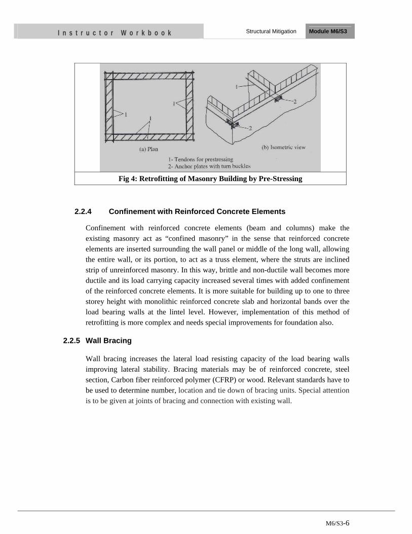
M6/S3-6
I n s t r u c t o r W o r k b o o k Structural Mitigation Module M6/S3
Fig 4: Retrofitting of Masonry Building by Pre-Stressing
2.2.4 Confinement with Reinforced Concrete Elements
Confinement with reinforced concrete elements (beam and columns) make the existing masonry act as “confined masonry” in the sense that reinforced concrete elements are inserted surrounding the wall panel or middle of the long wall, allowing the entire wall, or its portion, to act as a truss element, where the struts are inclined strip of unreinforced masonry. In this way, brittle and non-ductile wall becomes more ductile and its load carrying capacity increased several times with added confinement of the reinforced concrete elements. It is more suitable for building up to one to three storey height with monolithic reinforced concrete slab and horizontal bands over the load bearing walls at the lintel level. However, implementation of this method of retrofitting is more complex and needs special improvements for foundation also.
2.2.5 Wall Bracing
Wall bracing increases the lateral load resisting capacity of the load bearing walls improving lateral stability. Bracing materials may be of reinforced concrete, steel section, Carbon fiber reinforced polymer (CFRP) or wood. Relevant standards have to be used to determine number, location and tie down of bracing units. Special attention is to be given at joints of bracing and connection with existing wall.
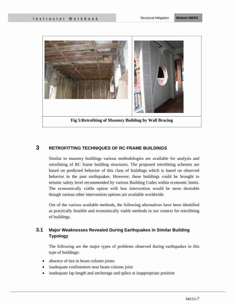
M6/S3-7
I n s t r u c t o r W o r k b o o k Structural Mitigation Module M6/S3
Fig 5:Retrofiting of Masonry Building by Wall Bracing
3 RETROFITTING TECHNIQUES OF RC FRAME BUILDINGS
Similar to masonry buildings various methodologies are available for analysis and retrofitting of RC frame building structures. The proposed retrofitting schemes are based on predicted behavior of this class of buildings which is based on observed behavior in the past earthquakes. However, these buildings could be brought to seismic safety level recommended by various Building Codes within economic limits. The economically viable option with less intervention would be more desirable though various other intervention options are available worldwide.
Out of the various available methods, the following alternatives have been identified as practically feasible and economically viable methods in our context for retrofitting of buildings.
3.1 Major Weaknesses Revealed During Earthquakes in Similar Building Typology
The following are the major types of problems observed during earthquakes in this type of buildings:
• absence of ties in beam column joints • inadequate confinement near beam column joint • inadequate lap length and anchorage and splice at inappropriate position
M6/S3-8
I n s t r u c t o r W o r k b o o k Structural Mitigation Module M6/S3
• low concrete strength • improperly anchored ties (90o hooks) • inadequate lateral stiffness • inadequate lateral strength • irregularities in plan and elevation • irregular distribution of loads and structural elements • other common structural deficiencies such as soft storey effect, short column effect,
strong beam-weak column connections etc.
3.2 Common Retrofitting Methods for the Reinforced Concrete Buildings
Various methodologies are available for analysis and retrofitting of frame structures. Earthquake resistance in RC frame buildings can be enhanced either by
a) Increasing seismic capacity of the building
This is a conventional approach to seismic retrofitting which increase the lateral force resistance of the building structure by increasing stiffness, strength and ductility and reducing irregularities. This can be done by two ways
1) Strengthening of original structural members
These include strengthening of
o Columns (reinforced concrete jacketing, steel profile jacketing, steel encasement, fiber wrap overlays)
o Beams (reinforced concrete jacketing, steel plate reinforcement, fiber-wrap overlays) Beam Column joint (reinforced concrete jacketing, steel plate reinforcement, fiber wrap overlays)
o shear wall (increase of wall thickness) o Slab (increase of slab thickness, improving slab to wall connection) o Infilled partition wall (reinforce infilled walls and anchor them into the
surrounding concrete frame members).
2) Introduction of New structural elements
The lateral force capacity of an existing structure may be increased by adding new structural elements to resist part or all of the seismic forces of the structure, leaving the old structure to resist only that part of the seismic action for which it is judge reliable. Newly added structural elements may be
o shear walls in a frame or skeleton structure o Infilled walls (reinforced concrete or masonry located in the plane of existing
columns and beams)
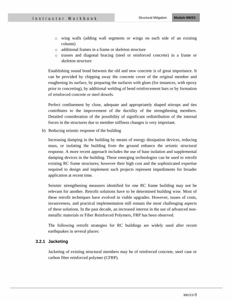
M6/S3-9
I n s t r u c t o r W o r k b o o k Structural Mitigation Module M6/S3
o wing walls (adding wall segments or wings on each side of an existing column)
o additional frames in a frame or skeleton structure o trusses and diagonal bracing (steel or reinforced concrete) in a frame or
skeleton structure
Establishing sound bond between the old and new concrete is of great importance. It can be provided by chipping away the concrete cover of the original member and roughening its surface, by preparing the surfaces with glues (for instances, with epoxy prior to concreting), by additional welding of bend reinforcement bars or by formation of reinforced concrete or steel dowels.
Perfect confinement by close, adequate and appropriately shaped stirrups and ties contributes to the improvement of the ductility of the strengthening members. Detailed consideration of the possibility of significant redistribution of the internal forces in the structures due to member stiffness changes is very important.
b) Reducing seismic response of the building
Increasing damping in the building by means of energy dissipation devices, reducing mass, or isolating the building from the ground enhance the seismic structural response. A more recent approach includes the use of base isolation and supplemental damping devices in the building. These emerging technologies can be used to retrofit existing RC frame structures; however their high cost and the sophisticated expertise required to design and implement such projects represent impediments for broader application at recent time.
Seismic strengthening measures identified for one RC frame building may not be relevant for another. Retrofit solutions have to be determined building wise. Most of these retrofit techniques have evolved in viable upgrades. However, issues of costs, invasiveness, and practical implementation still remain the most challenging aspects of these solutions. In the past decade, an increased interest in the use of advanced non-metallic materials or Fiber Reinforced Polymers, FRP has been observed.
The following retrofit strategies for RC buildings are widely used after recent earthquakes in several places:
3.2.1 Jacketing
Jacketing of existing structural members may be of reinforced concrete, steel case or carbon fiber reinforced polymer (CFRP).
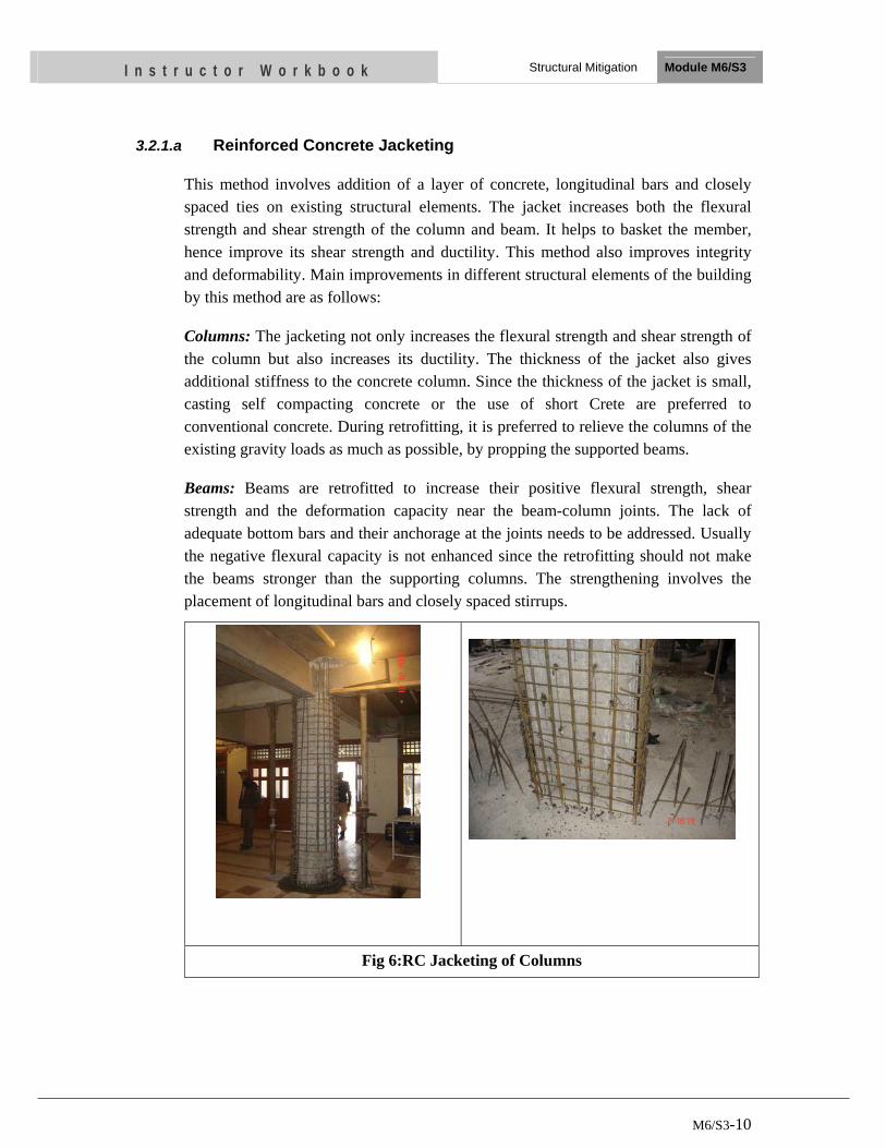
M6/S3-10
I n s t r u c t o r W o r k b o o k Structural Mitigation Module M6/S3
3.2.1.a Reinforced Concrete Jacketing
This method involves addition of a layer of concrete, longitudinal bars and closely spaced ties on existing structural elements. The jacket increases both the flexural strength and shear strength of the column and beam. It helps to basket the member, hence improve its shear strength and ductility. This method also improves integrity and deformability. Main improvements in different structural elements of the building by this method are as follows:
Columns: The jacketing not only increases the flexural strength and shear strength of the column but also increases its ductility. The thickness of the jacket also gives additional stiffness to the concrete column. Since the thickness of the jacket is small, casting self compacting concrete or the use of short Crete are preferred to conventional concrete. During retrofitting, it is preferred to relieve the columns of the existing gravity loads as much as possible, by propping the supported beams.
Beams: Beams are retrofitted to increase their positive flexural strength, shear strength and the deformation capacity near the beam-column joints. The lack of adequate bottom bars and their anchorage at the joints needs to be addressed. Usually the negative flexural capacity is not enhanced since the retrofitting should not make the beams stronger than the supporting columns. The strengthening involves the placement of longitudinal bars and closely spaced stirrups.
Fig 6:RC Jacketing of Columns
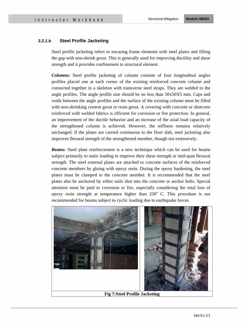
M6/S3-11
I n s t r u c t o r W o r k b o o k Structural Mitigation Module M6/S3
3.2.1.b Steel Profile Jacketing
Steel profile jacketing refers to encasing frame elements with steel plates and filling the gap with non-shrink grout. This is generally used for improving ductility and shear strength and it provides confinement to structural element.
Columns: Steel profile jacketing of column consists of four longitudinal angles profiles placed one at each corner of the existing reinforced concrete column and connected together in a skeleton with transverse steel straps. They are welded to the angle profiles. The angle profile size should be no less than 50x50X5 mm. Caps and voids between the angle profiles and the surface of the existing column must be filled with non-shrinking cement grout or resin grout. A covering with concrete or shotcrete reinforced with welded fabrics is efficient for corrosion or fire protection. In general, an improvement of the ductile behavior and an increase of the axial load capacity of the strengthened column is achieved. However, the stiffness remains relatively unchanged. If the plates are carried continuous to the floor slab, steel jacketing also improves flexural strength of the strengthened member, though not extensively.
Beams: Steel plate reinforcement is a new technique which can be used for beams subject primarily to static loading to improve their shear strength or mid-span flexural strength. The steel external plates are attached to concrete surfaces of the reinforced concrete members by gluing with epoxy resin. During the epoxy hardening, the steel plates must be clamped to the concrete member. It is recommended that the steel plates also be anchored by either nails shot into the concrete or anchor bolts. Special attention must be paid to corrosion or fire, especially considering the total loss of epoxy resin strength at temperature higher than 250o C. This procedure is not recommended for beams subject to cyclic loading due to earthquake forces.
Fig 7:Steel Profile Jacketing
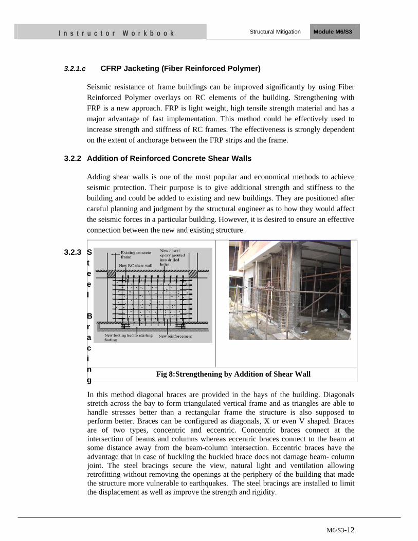
M6/S3-12
I n s t r u c t o r W o r k b o o k Structural Mitigation Module M6/S3
3.2.1.c CFRP Jacketing (Fiber Reinforced Polymer)
Seismic resistance of frame buildings can be improved significantly by using Fiber Reinforced Polymer overlays on RC elements of the building. Strengthening with FRP is a new approach. FRP is light weight, high tensile strength material and has a major advantage of fast implementation. This method could be effectively used to increase strength and stiffness of RC frames. The effectiveness is strongly dependent on the extent of anchorage between the FRP strips and the frame.
3.2.2 Addition of Reinforced Concrete Shear Walls
Adding shear walls is one of the most popular and economical methods to achieve seismic protection. Their purpose is to give additional strength and stiffness to the building and could be added to existing and new buildings. They are positioned after careful planning and judgment by the structural engineer as to how they would affect the seismic forces in a particular building. However, it is desired to ensure an effective connection between the new and existing structure.
3.2.3 Steel Bracing
In this method diagonal braces are provided in the bays of the building. Diagonals stretch across the bay to form triangulated vertical frame and as triangles are able to handle stresses better than a rectangular frame the structure is also supposed to perform better. Braces can be configured as diagonals, X or even V shaped. Braces are of two types, concentric and eccentric. Concentric braces connect at the intersection of beams and columns whereas eccentric braces connect to the beam at some distance away from the beam-column intersection. Eccentric braces have the advantage that in case of buckling the buckled brace does not damage beam- column joint. The steel bracings secure the view, natural light and ventilation allowing retrofitting without removing the openings at the periphery of the building that made the structure more vulnerable to earthquakes. The steel bracings are installed to limit the displacement as well as improve the strength and rigidity.
Fig 8:Strengthening by Addition of Shear Wall
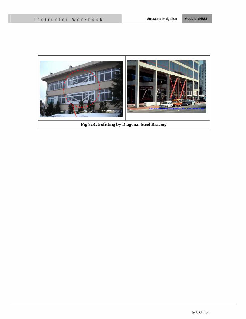
M6/S3-13
I n s t r u c t o r W o r k b o o k Structural Mitigation Module M6/S3
Fig 9:Retrofitting by Diagonal Steel Bracing
M6/S3-14
I n s t r u c t o r W o r k b o o k Structural Mitigation Module M6/S3
UNIT TEST
1. What is seismic strengthening or retrofitting
2. Write five different ways of strengthening masonry buildings?
• … • … • … • …
• …
3. Write three different ways of strengthening RC Frame buildings?
…
….
…
OBJECTIVES
As a result of this session, you should be able to:
• Discuss Structural Control System
• List two approaches of Passive Control System
• Discuss Active Control System
Instructor Workbook Module M6/S4
Developments in Earthquake Resistant Technology
M6/S3-1
CONTENTS
1 Introduction ...................................................................................................... 2 2 Structural Control ............................................................................................ 2
2.1 Passive Control System ............................................................................ 2
2.2 Active Control System .............................................................................. 2
3 Approaches of Passive Control ....................................................................... 3
3.1 Base Isolation Devices .............................................................................. 3
3.1.1 Types of Base Isolation Devices ................................................... 3
3.2 Passive Energy Dissipation Devices ......................................................... 4
3.2.1 Types of Passive Energy Devices ................................................. 5
3.3 Tuned Devices .......................................................................................... 8
3.3.1 Tuned Mass Dampers .................................................................... 9
3.3.2 Tuned Liquid Dampers ................................................................. 9
M6/S4-2
I n s t r u c t o r W o r k b o o k Developments in Earthquake Resistant Technology Module M 6/S4
1 INTRODUCTION
Structural control is defined as a mechanical system that is installed in a structure to reduce structural vibrations during loadings such as strong winds and earthquakes. The purpose of such a structural control system is to enhance the safety as well as improve the habitability of structures during these loading scenarios. In buildings of special use, like hospitals, monuments or buildings with sensitive instruments, the levels of damage and vibrations that occur during earthquakes may not be acceptable. For these situations, methods are required to reduce, or control, the seismic effects. Structural Control refers to these methods which are employed to control the response of civil engineering structures.
2 STRUCTURAL CONTROL
Structural Control techniques can be broadly classified into two types, namely Passive Control and Active Control. Techniques which combine the favorable characteristics of these two techniques are termed hybrid methods.
2.1 Passive Control System
A passive control system is one in which structural vibrations are reduced from a passive control device imparting a force upon a structure out of response to the motion of the structure. Passive control has many benefits associated with it. First, no external power is required for the passive device to work. This makes a passive device an economical solution. In addition, the device will generally be smaller in size than an active control device. Furthermore, passive devices have been in existence for well over 50 years and have been thoroughly researched and tested resulting in a reliable product. However, there is a negative aspect to the passive device and that is only a limited amount of control can be attained. Even in light of this fact, they are still considered a very cost-effective solution to controlling structures. Examples of passive control devices include base isolation, tuned mass dampers, viscous dampers, elasto-plastic dampers, metallic yield dampers and friction dampers.
2.2 Active Control System
An active control system is a much more complex system than the passive control system. External power is employed to power actuators located in the structure in order to apply forces that can put in or take out energy from the system. In order for the actuators to properly apply the desired forces, sensors need to be placed within the structure in order to measure structural response. These sensors relay response information to a central computer that then uses this information to calculate desired actuator forces. The advantage of an active control system is that the system attains excellent control results. However, there are many drawbacks to using an active control system. They are very expensive systems to design and are expensive to operate due to the large amounts of power they need. Furthermore, they tend to take up more space than passive control devices. Some examples of active control devices
M6/S4-3
I n s t r u c t o r W o r k b o o k Developments in Earthquake Resistant Technology Module M 6/S4
include the active mass driver system, the active tuned mass system, and the active-passive composite tuned mass damper.
The last broad category of control is semi-active or hybrid control. Semi-active control falls between passive and active on the control spectrum. A semi-active control system is similar to an active system in that actuators operating on external power are used but the actuators do not add energy to the structure in anyway. The actuators are used to control or assist a passive control device. The inherent benefit of a semi-active control device is that the actuator used does not require large amounts of external power. Semi-active systems are more aggressive than passive systems and usually obtain control results close to that of an active control system. An active variable stiffness system as well as the active variable damping system is considered semi-active systems
3 APPROACHES OF PASSIVE CONTROL
Two approaches are conceived in Passive Structural Control.
3.1 Base Isolation Devices
Base isolation, also known as seismic or base isolation system, is a collection of structural elements which should substantially decouple a superstructure from its substructure resting on a shaking ground thus protecting a building or non-building structure's integrity .The technique of base isolation involves the introduction of devices above the foundation level of a building to increase the flexibility in the horizontal plane. In addition, damping elements are introduced in the superstructure, so as to reduce the relative displacements of the floor levels during an earthquake.
Base isolation is the most powerful tool of the earthquake engineering pertaining to the passive structural vibration control technologies. It is meant to enable a building or non-building structure to survive a potentially devastating seismic impact through a proper initial design or subsequent modifications. In some cases, application of base isolation can raise both a structure's seismic performance and its seismic sustainability considerably. Contrary to popular belief base isolation does not make a building earthquake proof as there is no such thing.
3.1.1 Types of Base Isolation Devices
The types of base isolation devices are as follows (Naeim and Kelly, 1999).
i) Laminated rubber (or elastomeric) bearings
ii) Laminated rubber bearings with lead cores
iii) Sliding bearings
iv) Friction pendulum devices
In laminated rubber bearings, layers of rubber alternated with steel shims are sandwiched between two steel plates. In laminated rubber bearings with lead cores,
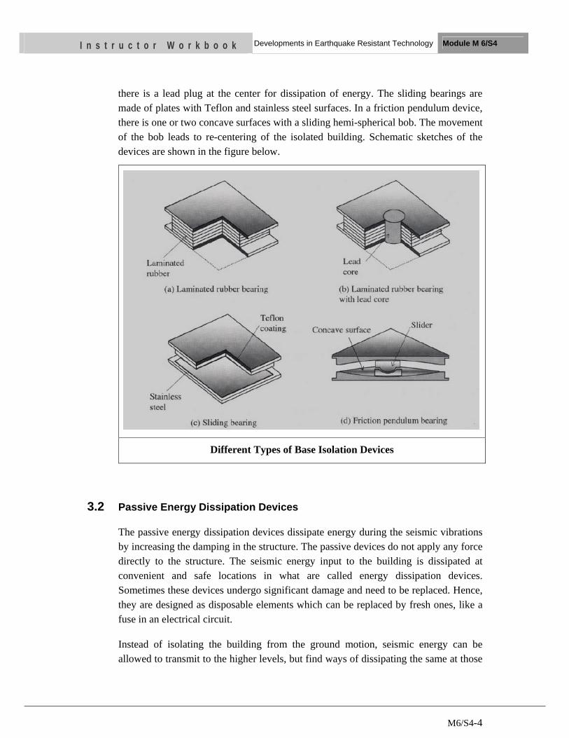
M6/S4-4
I n s t r u c t o r W o r k b o o k Developments in Earthquake Resistant Technology Module M 6/S4
there is a lead plug at the center for dissipation of energy. The sliding bearings are made of plates with Teflon and stainless steel surfaces. In a friction pendulum device, there is one or two concave surfaces with a sliding hemi-spherical bob. The movement of the bob leads to re-centering of the isolated building. Schematic sketches of the devices are shown in the figure below.
Different Types of Base Isolation Devices
3.2 Passive Energy Dissipation Devices
The passive energy dissipation devices dissipate energy during the seismic vibrations by increasing the damping in the structure. The passive devices do not apply any force directly to the structure. The seismic energy input to the building is dissipated at convenient and safe locations in what are called energy dissipation devices. Sometimes these devices undergo significant damage and need to be replaced. Hence, they are designed as disposable elements which can be replaced by fresh ones, like a fuse in an electrical circuit.
Instead of isolating the building from the ground motion, seismic energy can be allowed to transmit to the higher levels, but find ways of dissipating the same at those
M6/S4-5
I n s t r u c t o r W o r k b o o k Developments in Earthquake Resistant Technology Module M 6/S4
levels. It is also possible to convert this energy into other useful forms like heat, instead of merely dissipating it.
The energy balance relationship for a structure during an earthquake can be represented by the following equation.
EI = EK + ES + ED
Here,
EI = earthquake input energy
EK =kinetic energy generated in the structure due to the motion of the masses
ES =strain energy generated in structure due to deformations of the members
ED= energy dissipated due to damping
The objective of the use of energy dissipating devices is to increase ED so that, for a given EI, the value of ES is minimized. This means that the structural members will undergo smaller deformations for a given level of input energy and thus damage will be reduced.
3.2.1 Types of Passive Energy Devices
The types of passive energy devices are as follows
a. Friction Dampers
b. Metallic Dampers
c. Visco-elastic dampers
d. Viscous Dampers
3.2.1.a Friction Dampers
Friction dampers are designed to have moving parts that will slide over each other during a strong earthquake. When the parts slide over each other, they create friction which uses some of the energy from the earthquake that goes into the building.
The type of friction dampers depend on the mode of sliding. Figure below shows a device that is located at the intersection of X-braces in a frame. When loaded, the tension brace induces slippage at the friction joint. Consequently, the four links force the compression brace to slip. In this manner, energy is dissipated in both braces.
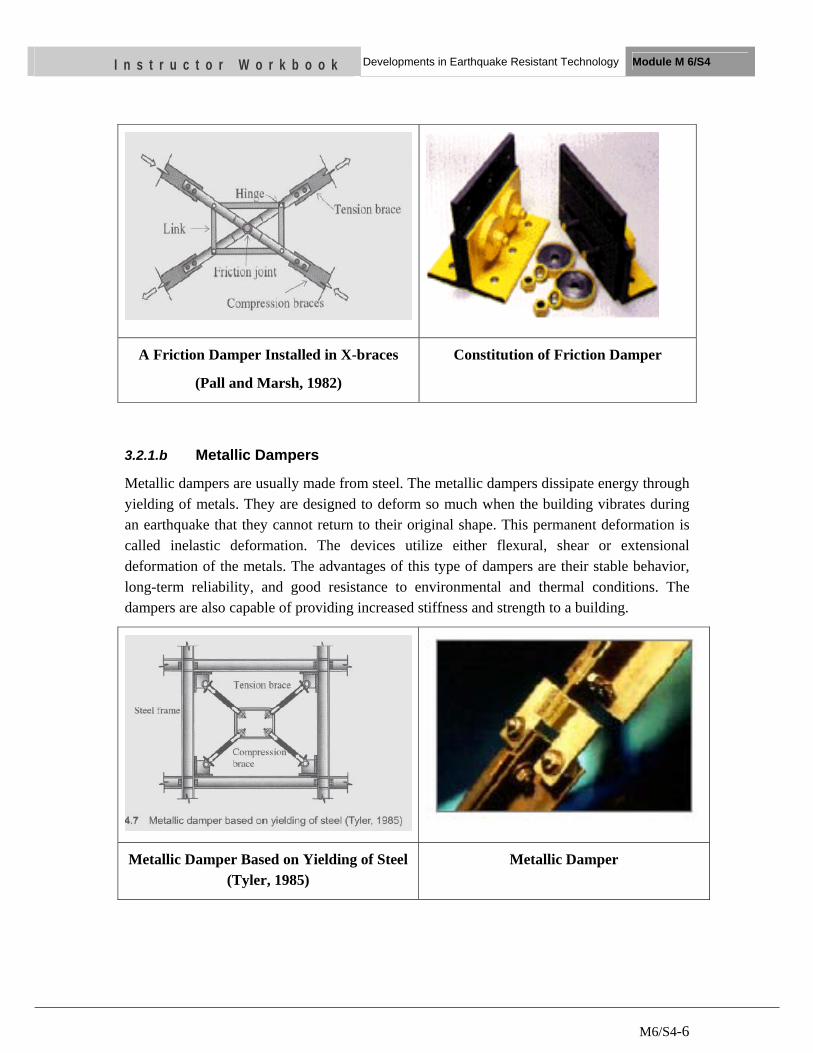
M6/S4-6
I n s t r u c t o r W o r k b o o k Developments in Earthquake Resistant Technology Module M 6/S4
A Friction Damper Installed in X-braces
(Pall and Marsh, 1982)
Constitution of Friction Damper
3.2.1.b Metallic Dampers
Metallic dampers are usually made from steel. The metallic dampers dissipate energy through yielding of metals. They are designed to deform so much when the building vibrates during an earthquake that they cannot return to their original shape. This permanent deformation is called inelastic deformation. The devices utilize either flexural, shear or extensional deformation of the metals. The advantages of this type of dampers are their stable behavior, long-term reliability, and good resistance to environmental and thermal conditions. The dampers are also capable of providing increased stiffness and strength to a building.
Metallic Damper Based on Yielding of Steel (Tyler, 1985)
Metallic Damper
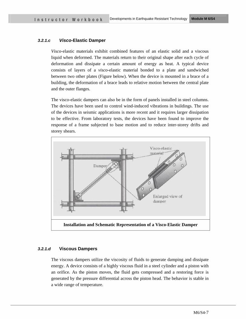
M6/S4-7
I n s t r u c t o r W o r k b o o k Developments in Earthquake Resistant Technology Module M 6/S4
3.2.1.c Visco-Elastic Damper
Visco-elastic materials exhibit combined features of an elastic solid and a viscous liquid when deformed. The materials return to their original shape after each cycle of deformation and dissipate a certain amount of energy as heat. A typical device consists of layers of a visco-elastic material bonded to a plate and sandwiched between two other plates (Figure below). When the device is mounted in a brace of a building, the deformation of a brace leads to relative motion between the central plate and the outer flanges.
The visco-elastic dampers can also be in the form of panels installed in steel columns. The devices have been used to control wind-induced vibrations in buildings. The use of the devices in seismic applications is more recent and it requires larger dissipation to be effective. From laboratory tests, the devices have been found to improve the response of a frame subjected to base motion and to reduce inter-storey drifts and storey shears.
Installation and Schematic Representation of a Visco-Elastic Damper
3.2.1.d Viscous Dampers
The viscous dampers utilize the viscosity of fluids to generate damping and dissipate energy. A device consists of a highly viscous fluid in a steel cylinder and a piston with an orifice. As the piston moves, the fluid gets compressed and a restoring force is generated by the pressure differential across the piston head. The behavior is stable in a wide range of temperature.
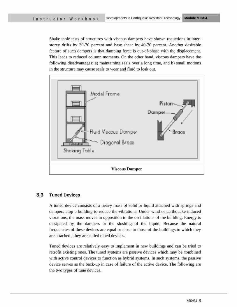
M6/S4-8
I n s t r u c t o r W o r k b o o k Developments in Earthquake Resistant Technology Module M 6/S4
Shake table tests of structures with viscous dampers have shown reductions in inter-storey drifts by 30-70 percent and base shear by 40-70 percent. Another desirable feature of such dampers is that damping force is out-of-phase with the displacement. This leads to reduced column moments. On the other hand, viscous dampers have the following disadvantages: a) maintaining seals over a long time, and b) small motions in the structure may cause seals to wear and fluid to leak out.
Viscous Damper
3.3 Tuned Devices
A tuned device consists of a heavy mass of solid or liquid attached with springs and dampers atop a building to reduce the vibrations. Under wind or earthquake induced vibrations, the mass moves in opposition to the oscillations of the building. Energy is dissipated by the dampers or the sloshing of the liquid. Because the natural frequencies of these devices are equal or close to those of the buildings to which they are attached , they are called tuned devices.
Tuned devices are relatively easy to implement in new buildings and can be tried to retrofit existing ones. The tuned systems are passive devices which may be combined with active control devices to function as hybrid systems. In such systems, the passive device serves as the back-up in case of failure of the active device. The following are the two types of tune devices.
M6/S4-9
I n s t r u c t o r W o r k b o o k Developments in Earthquake Resistant Technology Module M 6/S4
3.3.1 Tuned Mass Dampers
A typical Tuned Mass Dampers (TMD) consists of a mass (usually of steel, concrete or lead) attached to the building by a spring and a viscous damper in parallel. When the building vibrates, it excites the TMD and the kinetic energy is transferred to the TMD and is absorbed by the damper. The mass of the TMD usually experiences large displacements.
A tuned mass damper is characterized by its mass, frequency and damping ratios. The mass ratio is defined as the TMD mass to that of the building. The frequency (tuning) ratio is defined as the ratio of the fundamental frequency of the TMD to that of building. The optimum tuning and damping ratios are selected for design of the system.
3.3.2 Tuned Liquid Dampers
A typical Tuned Liquid Damper (TLD) consists of a tank filled with shallow liquid. The sloshing motion of the liquid during vibrations dissipates energy. The dissipation is enhanced by wave breaking and auxiliary damping appurtenances such as nets or floating beads. The principle of absorbing the kinetic energy of the structure is similar to TMDs, where the fluid functions as the moving mass and the restoring force is generated by gravity. The TLDs have several advantages over TMDs, such as reducing the motion in two directions simultaneously and not requiring large stroke lengths. Also, the mass of water or other fluid is relatively small compared to the large mass of the TMDs to achieve the same damping effect.
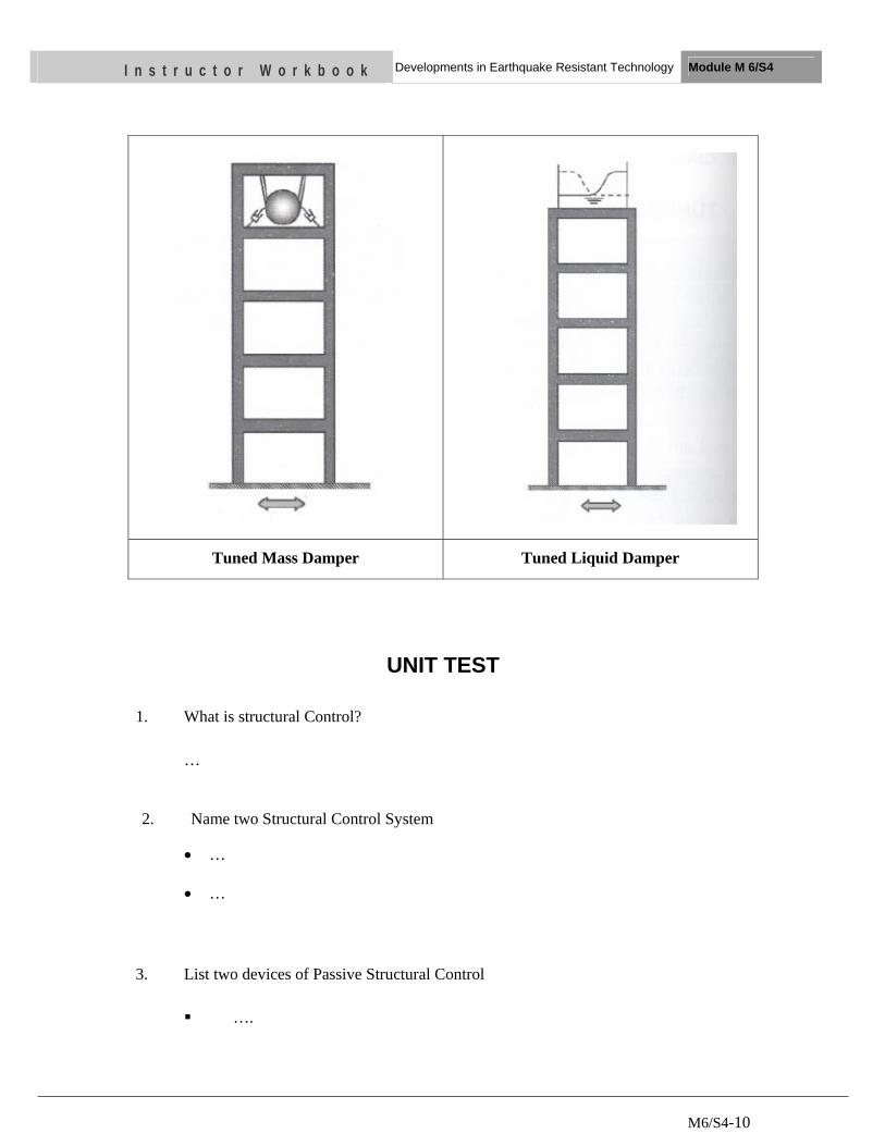
M6/S4-10
I n s t r u c t o r W o r k b o o k Developments in Earthquake Resistant Technology Module M 6/S4
Tuned Mass Damper Tuned Liquid Damper
UNIT TEST
1. What is structural Control?
…
2. Name two Structural Control System
• … • …
3. List two devices of Passive Structural Control
….
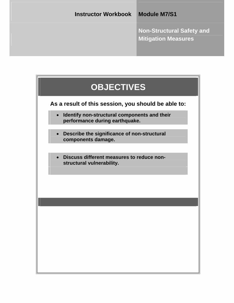
OBJECTIVES
As a result of this session, you should be able to:
• Identify non-structural components and their performance during earthquake.
• Describe the significance of non-structural components damage.
• Discuss different measures to reduce non-structural vulnerability.
Instructor Workbook Module M7/S1
Non-Structural Safety and Mitigation Measures
M7/S1- 1
CONTENTS
1 Nonstructural Elements .............................................................................................................. 3
2 Performance of Nonstructural Components during earthquake .......................................... 4
2.1 Inertial failure ..................................................................................................................... 4
2.2 Displacement / Deformation failures ................................................................................ 5
3 Significance of Nonstructural Damage ..................................................................................... 7
3.1 Life Safety (LS) ................................................................................................................. 8
3.2 Property Loss ..................................................................................................................... 9
3.3 Functional Loss (FL) ....................................................................................................... 10
4 Mitigation Measures ................................................................................................................. 12
4.1 6R Mitigation Measure .................................................................................................... 12
4.1.1 Removal ............................................................................................................. 13
4.1.2 Relocation .......................................................................................................... 13
4.1.3 Restrain .............................................................................................................. 13
4.1.4 Reinforcement .................................................................................................... 13
4.1.5 Replace ............................................................................................................... 13
4.1.6 Reduce................................................................................................................ 14
4.2 Other mitigation measures ............................................................................................... 14
4.2.1 Anchorage .......................................................................................................... 14
4.2.2 Flexible Couplings ............................................................................................. 15
4.2.3 Modification ...................................................................................................... 15
4.2.4 Hooking ............................................................................................................. 15
4.2.5 Strapping ............................................................................................................ 16
5 Some examples of non structural mitigation measures ........................................................ 16
5.1 Ceiling and overhead ....................................................................................................... 16
5.1.1 Light Fixtures- Hanging / Pendant .................................................................... 16
5.1.2 Ceiling Recessed Light Fixtures & HVAC Registers ....................................... 16
5.1.3 Suspended Ceilings ............................................................................................ 16
5.1.4 Hanging Displays & Plants ............................................................................... 17
5.1.5 Suspended Space Heaters / AC Units ............................................................... 17
M7/S1- 2
5.1.6 Conduits / Piping/ Ductwork ............................................................................. 17
5.1.7 Tile Roofing ....................................................................................................... 17
5.1.8 Unreinforced Masonry Chimney (exterior) ...................................................... 17
5.2 Walls and wall mounted .................................................................................................. 17
5.2.1 Shelving ............................................................................................................. 17
5.2.2 Wall Mounted T.V. Video Monitor & Speakers............................................... 18
5.2.3 Pictures / Wall Decorations / Signs ................................................................... 18
5.2.4 Fire Extinguisher with Mounting Bracket ........................................................ 18
5.2.5 Free Standing & Cubical Partitions ................................................................... 18
5.2.6 Entry Glass ......................................................................................................... 18
5.3 Furniture and Equipment ................................................................................................. 18
5.3.1 File Cabinets ...................................................................................................... 18
5.3.2 Desktop / Countertop Equipment ...................................................................... 19
5.3.3 Equipment on wheel or roller (video, projector) .............................................. 19
5.3.4 Display Cases / Art Objects / Potted Plants ...................................................... 19
5.3.5 Aquariums .......................................................................................................... 19
5.3.6 Refrigerators ...................................................................................................... 19
5.3.7 Gas Cylinders ..................................................................................................... 19
5.3.8 Gas Piping (shut-off valve & flexible connectors) ........................................... 20
5.3.9 Electrical Equipment (cabinets, switchgear, transformers) .............................. 20
5.3.10 Mechanical Equipment (chillers, fans) ............................................................. 20
5.3.11 Plumbing Equipment (water heater, tanks, pumps) .......................................... 20
5.3.12 Kitchen Equipment (oven, range, hood, refrigerator/freezer, dishwasher) ...... 20
M7/S1- 3
I n s t r u c t o r W o r k b o o k Non-structural Safety and Mitigation Measures Module M7/S1
1 NONSTRUCTURAL ELEMENTS
Structural elements are typically components associated with the primary building
structure used to provide the support and environmental enclosure for the facility
functions. The non-structural parts of a building include all parts of the building and
its contents with the exception of the structure, in other words, everything except the
columns, floors, beams etc. Typically, non-structural items are not analyzed by
engineers and may be specified by architects, mechanical engineers, electrical
engineers, and interior designers. Some systems like water supply, drainage,
electricity etc. may be designed by the professionals, but consideration for earthquake
safety are not incorporated in such designs. In most cases, nonstructural elements are
purchased by the owners after the construction is finished without the involvement of
any design professional. Nonstructural items support the function of the facility and
typically include the following.
• Architectural Components
• Cladding
• Interior partition walls
• False ceilings and lights
• Chimney
• Parapet wall
• Racks and shelving
• Equipment and Systems
• Electrical power and distribution systems
• Heating, ventilation, and cooling systems
• Fire protection systems
• Emergency power system
• Sewerage System
• Drinking water
• Gas pipes
M7/S1- 4
I n s t r u c t o r W o r k b o o k Non-structural Safety and Mitigation Measures Module M7/S1
• Building Contents and Inventory
• Furniture
• Cupboard
• Glass objects
• Computer equipment
2 PERFORMANCE OF NONSTRUCTURAL COMPONENTS DURING EARTHQUAKE
The primary types of failures experienced by nonstructural components due to
earthquake can be classified as either inertial failures or displacement/deformation
failures.
2.1 Inertial failure
When a building is shaken during an earthquake, the base of the building moves in
harmony with the ground, but the entire building and the building contents above the
base will experience inertial forces. These inertial forces can be explained by using
the analogy of a passenger in a moving vehicle. As a passenger, you experience
inertial forces whenever the vehicle is accelerating or decelerating rapidly. If the
vehicle is accelerating, you may feel yourself pushed backward against the seat, since
the inertial force on your body acts in the direction opposite that of the acceleration. If
the vehicle is decelerating or breaking, you may be thrown forward in your seat.
Although the engineering aspects of inertial forces are more complex than a simple
principle of physics, the law first formulated by Sir Isaac Newton, F=ma, or force is
equal to the mass times acceleration, is the basic principle involved. In general, the
earthquake inertial forces are greater if the building or object within the building
weighs more or if the acceleration or severity of the shaking is greater.
File cabinets, emergency-power generating equipment, freestanding bookshelves,
office equipment, water tanks, flower pots and items stored on shelves or racks can all
be damaged because of inertial forces. When an earthquake shakes unstrained items,

M7/S1- 5
I n s t r u c t o r W o r k b o o k Non-structural Safety and Mitigation Measures Module M7/S1
inertial forces may cause them to slide, swing, strike other objects, or overturn. Items
may slide off shelves and fall to the floor. One misconception is that large, heavy
objects are stable and not as vulnerable to earthquake damage as lighter objects,
perhaps because we may have difficulty moving them. In fact, since inertial forces
during an earthquake are proportional to the mass of the object, heavy objects are
more likely to overturn than lighter ones with the same dimensions.
Thus the inertial failures are failures caused by:
• Excessive shaking of the component
• Component rocking due to unanchored or marginally anchored conditions
• Component sliding due to unanchored conditions
2.2 Displacement / Deformation failures
During an earthquake, building structures distort, or bend, side to side in response to
the earthquake forces. For example, the top of a tall building may incline a feet in
each direction during an earthquake. The distortion over the height of each story,
known as the story drift, might range from ¼ inches to several inches, depending on
the size of the earthquake and the characteristics of the particular building structure.
Windows, partitions and other items that are tightly locked into the structure are
forced to go along for the ride. As the columns or walls distort and become slightly
Figure: Overturned computer equipmentFigure: Rooftop AC units
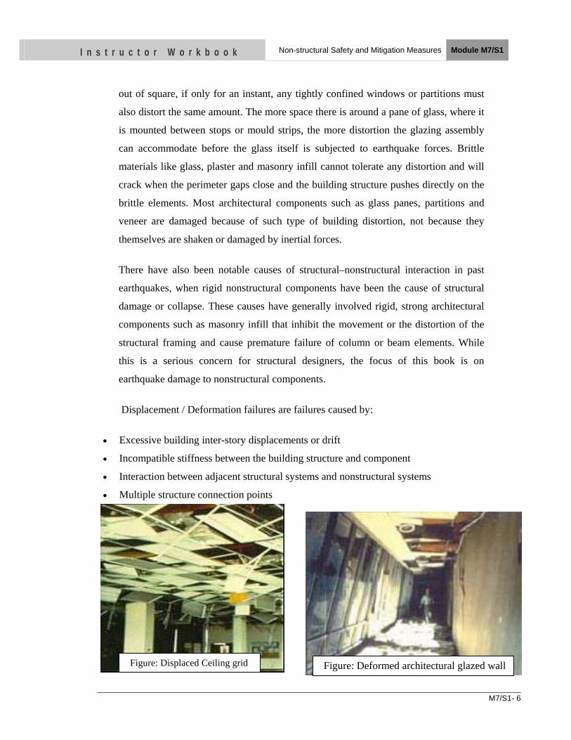
M7/S1- 6
I n s t r u c t o r W o r k b o o k Non-structural Safety and Mitigation Measures Module M7/S1
out of square, if only for an instant, any tightly confined windows or partitions must
also distort the same amount. The more space there is around a pane of glass, where it
is mounted between stops or mould strips, the more distortion the glazing assembly
can accommodate before the glass itself is subjected to earthquake forces. Brittle
materials like glass, plaster and masonry infill cannot tolerate any distortion and will
crack when the perimeter gaps close and the building structure pushes directly on the
brittle elements. Most architectural components such as glass panes, partitions and
veneer are damaged because of such type of building distortion, not because they
themselves are shaken or damaged by inertial forces.
There have also been notable causes of structural–nonstructural interaction in past
earthquakes, when rigid nonstructural components have been the cause of structural
damage or collapse. These causes have generally involved rigid, strong architectural
components such as masonry infill that inhibit the movement or the distortion of the
structural framing and cause premature failure of column or beam elements. While
this is a serious concern for structural designers, the focus of this book is on
earthquake damage to nonstructural components.
Displacement / Deformation failures are failures caused by:
• Excessive building inter-story displacements or drift
• Incompatible stiffness between the building structure and component
• Interaction between adjacent structural systems and nonstructural systems
• Multiple structure connection points
Figure: Displaced Ceiling grid Figure: Deformed architectural glazed wall
M7/S1- 7
I n s t r u c t o r W o r k b o o k Non-structural Safety and Mitigation Measures Module M7/S1
3 SIGNIFICANCE OF NONSTRUCTURAL DAMAGE
The three risk categories are also sometimes referred to as: the 3Ds: Deaths, Dollars,
and Downtime; the 3Cs: Casualties, Cost, and Continuity; or merely Safety, Property,
and Function.
The failures of nonstructural components during an earthquake may result in injuries
or fatalities, cause costly property damage to buildings and their contents; and force
the closure of residential, medical and manufacturing facilities, businesses, and
government offices until appropriate repairs are completed. The cost of loss of
operations, service, market share, and business continuity or interruption can exceed
the value of the building itself. The potential consequences of earthquake damage to
nonstructural components are typically divided into three types of risk:
• Life Safety
• Property Loss
• Functional Loss
Damage to a particular nonstructural item may present differing degrees of risk in
each of these three categories. In addition, damage to the item may result in direct
injury or loss, or the injury or loss may be a secondary effect or a consequence of the
failure of the item.
While it may make sense to implement simple and inexpensive nonstructural
protection measures even in a building with structural hazards, the relative structural
and nonstructural risks should be considered, so that limited resources can be used in
the most effective manner. It would give little comfort to know that the pipes and
ceilings were all well anchored in an unreinforced masonry structure that could
collapse during an earthquake.
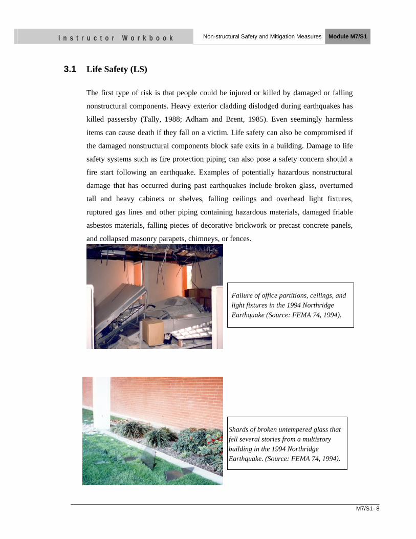
M7/S1- 8
I n s t r u c t o r W o r k b o o k Non-structural Safety and Mitigation Measures Module M7/S1
3.1 Life Safety (LS)
The first type of risk is that people could be injured or killed by damaged or falling
nonstructural components. Heavy exterior cladding dislodged during earthquakes has
killed passersby (Tally, 1988; Adham and Brent, 1985). Even seemingly harmless
items can cause death if they fall on a victim. Life safety can also be compromised if
the damaged nonstructural components block safe exits in a building. Damage to life
safety systems such as fire protection piping can also pose a safety concern should a
fire start following an earthquake. Examples of potentially hazardous nonstructural
damage that has occurred during past earthquakes include broken glass, overturned
tall and heavy cabinets or shelves, falling ceilings and overhead light fixtures,
ruptured gas lines and other piping containing hazardous materials, damaged friable
asbestos materials, falling pieces of decorative brickwork or precast concrete panels,
and collapsed masonry parapets, chimneys, or fences.
Failure of office partitions, ceilings, and light fixtures in the 1994 Northridge Earthquake (Source: FEMA 74, 1994).
Shards of broken untempered glass that fell several stories from a multistory building in the 1994 Northridge Earthquake. (Source: FEMA 74, 1994).
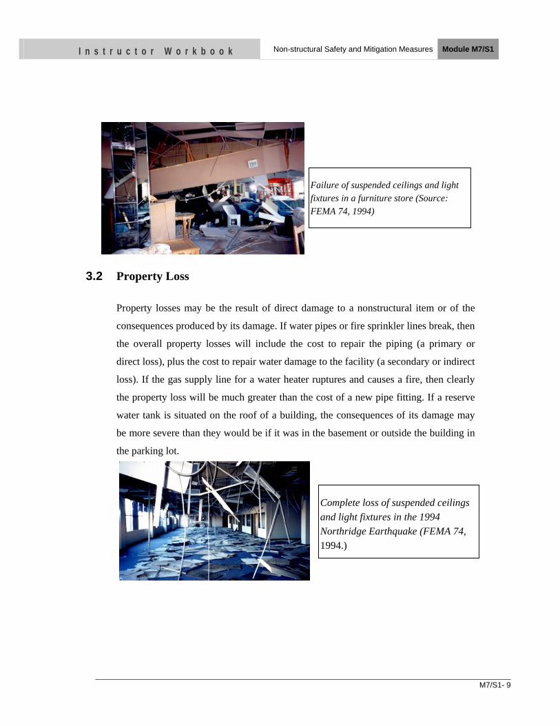
M7/S1- 9
I n s t r u c t o r W o r k b o o k Non-structural Safety and Mitigation Measures Module M7/S1
.
F
3.2 Property Loss
Property losses may be the result of direct damage to a nonstructural item or of the
consequences produced by its damage. If water pipes or fire sprinkler lines break, then
the overall property losses will include the cost to repair the piping (a primary or
direct loss), plus the cost to repair water damage to the facility (a secondary or indirect
loss). If the gas supply line for a water heater ruptures and causes a fire, then clearly
the property loss will be much greater than the cost of a new pipe fitting. If a reserve
water tank is situated on the roof of a building, the consequences of its damage may
be more severe than they would be if it was in the basement or outside the building in
the parking lot.
Failure of suspended ceilings and light fixtures in a furniture store (Source: FEMA 74, 1994)
Complete loss of suspended ceilings and light fixtures in the 1994 Northridge Earthquake (FEMA 74, 1994.)
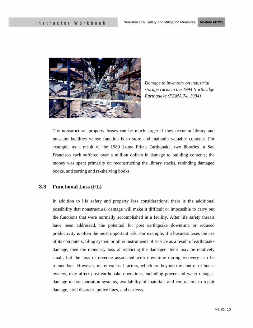
M7/S1- 10
I n s t r u c t o r W o r k b o o k Non-structural Safety and Mitigation Measures Module M7/S1
The nonstructural property losses can be much larger if they occur at library and
museum facilities whose function is to store and maintain valuable contents. For
example, as a result of the 1989 Loma Prieta Earthquake, two libraries in San
Francisco each suffered over a million dollars in damage to building contents; the
money was spent primarily on reconstructing the library stacks, rebinding damaged
books, and sorting and re-shelving books.
3.3 Functional Loss (FL)
In addition to life safety and property loss considerations, there is the additional
possibility that nonstructural damage will make it difficult or impossible to carry out
the functions that were normally accomplished in a facility. After life safety threats
have been addressed, the potential for post earthquake downtime or reduced
productivity is often the most important risk. For example, if a business loses the use
of its computers, filing system or other instruments of service as a result of earthquake
damage, then the monetary loss of replacing the damaged items may be relatively
small, but the loss in revenue associated with downtime during recovery can be
tremendous. However, many external factors, which are beyond the control of house
owners, may affect post earthquake operations, including power and water outages,
damage to transportation systems, availability of materials and contractors to repair
damage, civil disorder, police lines, and curfews.
Damage to inventory on industrial storage racks in the 1994 Northridge Earthquake (FEMA 74, 1994)
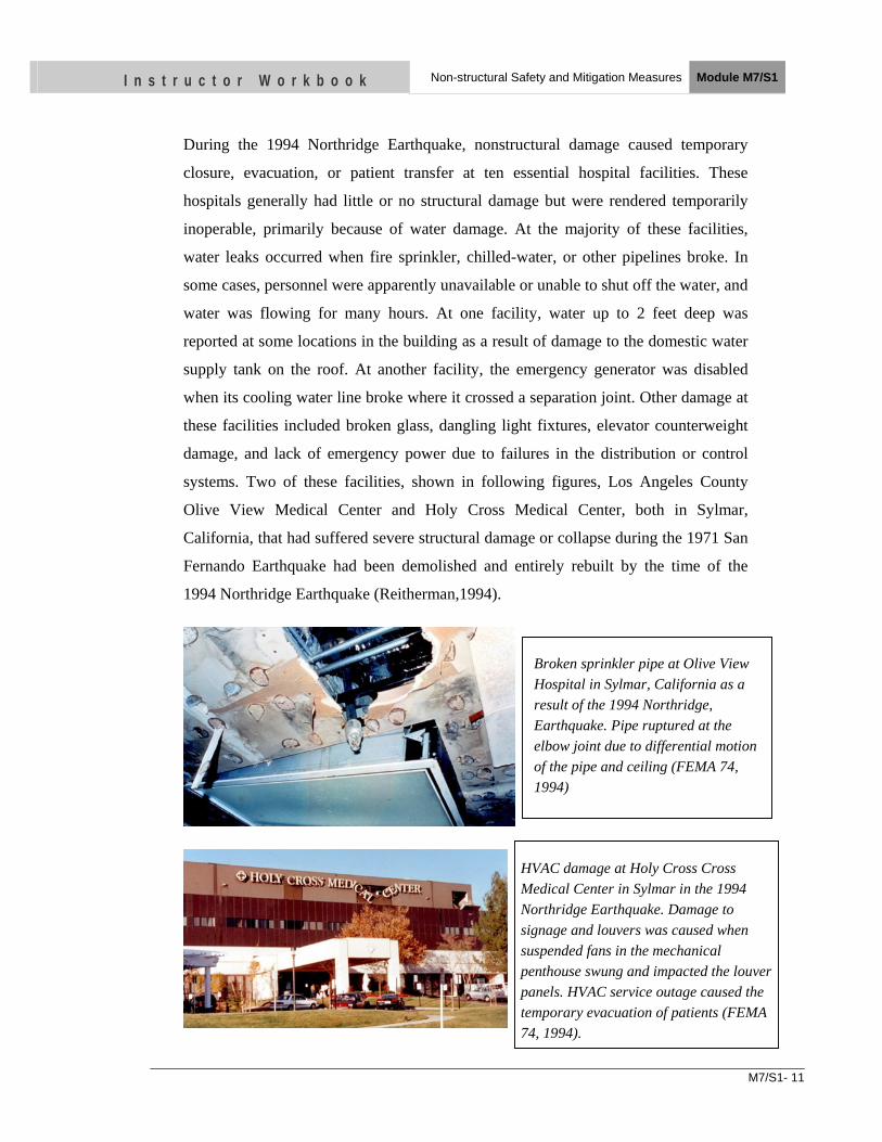
M7/S1- 11
I n s t r u c t o r W o r k b o o k Non-structural Safety and Mitigation Measures Module M7/S1
During the 1994 Northridge Earthquake, nonstructural damage caused temporary
closure, evacuation, or patient transfer at ten essential hospital facilities. These
hospitals generally had little or no structural damage but were rendered temporarily
inoperable, primarily because of water damage. At the majority of these facilities,
water leaks occurred when fire sprinkler, chilled-water, or other pipelines broke. In
some cases, personnel were apparently unavailable or unable to shut off the water, and
water was flowing for many hours. At one facility, water up to 2 feet deep was
reported at some locations in the building as a result of damage to the domestic water
supply tank on the roof. At another facility, the emergency generator was disabled
when its cooling water line broke where it crossed a separation joint. Other damage at
these facilities included broken glass, dangling light fixtures, elevator counterweight
damage, and lack of emergency power due to failures in the distribution or control
systems. Two of these facilities, shown in following figures, Los Angeles County
Olive View Medical Center and Holy Cross Medical Center, both in Sylmar,
California, that had suffered severe structural damage or collapse during the 1971 San
Fernando Earthquake had been demolished and entirely rebuilt by the time of the
1994 Northridge Earthquake (Reitherman,1994).
Broken sprinkler pipe at Olive View Hospital in Sylmar, California as a result of the 1994 Northridge, Earthquake. Pipe ruptured at the elbow joint due to differential motion of the pipe and ceiling (FEMA 74, 1994)
HVAC damage at Holy Cross Cross Medical Center in Sylmar in the 1994 Northridge Earthquake. Damage to signage and louvers was caused when suspended fans in the mechanical penthouse swung and impacted the louver panels. HVAC service outage caused the temporary evacuation of patients (FEMA 74, 1994).
M7/S1- 12
I n s t r u c t o r W o r k b o o k Non-structural Safety and Mitigation Measures Module M7/S1
Figure: HVAC damage at Holy Cross Medical Center in Sylmar in the 1994
Northridge Earthquake.
Damage to signage and louvers was caused when suspended fans in the mechanical
penthouse swung and impacted the louver panels. HVAC service outage caused the
temporary evacuation of patients (FEMA 74, 1994).
In some cases, cleanup costs or the value of lost employee labor are not the key
measures of the post earthquake impact of an earthquake. For example, data
processing facilities or financial institutions must remain operational on a minute-by-
minute basis in order to maintain essential services and to monitor transactions at
distant locations. In such cases, spilled files or damage to communications and
computer equipment may represent less tangible but more significant outage costs.
Hospitals and fire and police stations are facilities with essential functions that must
remain operational after an earthquake.
4 MITIGATION MEASURES
4.1 6R Mitigation Measure
Non-structural mitigation measures are easy and cost effective. For easy
understanding and remembrance, major mitigation measures can be assigned to 6R.
6R mitigation measures are:
• Removal
• Relocation
• Restrain
• Reinforcement
• Replace
• Reduce
M7/S1- 13
I n s t r u c t o r W o r k b o o k Non-structural Safety and Mitigation Measures Module M7/S1
4.1.1 Removal
Removal is probably the best mitigation option in many cases. All unnecessary or non-
essential documents and materials stored near the working place or near important
equipment shall be removed. One solution would be better fastenings or the use of
stronger supports, but the most effective solution would be removal and replacement.
4.1.2 Relocation
Relocation would reduce danger in many cases. For example, a very heavy object on top
of a shelf could fall and seriously injure someone as well as break thereby causing
economic losses. But by relocating heavy equipment and materials from upper shelves to
lower shelves the risk could be mitigated. This is the case in most of hospitals where the
functionality of the stores of operation theatres could be improved.
Cupboards and book shelves kept near an exit door or passage, which can obstruct the
way and cause human death or injury during an earthquake event, are typical examples.
These book shelves and cupboards should easily be relocated to other places where the
potential dangers would be reduced.
4.1.3 Restrain
Restricted mobility for certain objects such as gas cylinders and power generators is a
good measure. It does not matter if the cylinders shift as long as they do not fall and
break their valves. Sometimes back-up power generators are mounted on springs to
reduce the noise and vibrations when they are working, but these springs would amplify
ground motion. Therefore, restraining supports or chains should be placed around the
springs to keep the generator from shifting or being knocked off its stand.
4.1.4 Reinforcement
Reinforcement is feasible in many cases. For example, an un-reinforced infill wall or a
chimney may be strengthened without great expense by covering the surface with wire
mesh and cementing it.
4.1.5 Replace
Replace with something that does not represent a seismic hazard is appropriate in some
situations. For example, a heavy, tiled roof does not only make the roof of a building
M7/S1- 14
I n s t r u c t o r W o r k b o o k Non-structural Safety and Mitigation Measures Module M7/S1
heavy, it is also more susceptible to the movement of an earthquake. The individual tiles
tend to come off thus creating a hazard for people and objects. One solution would be to
change it with a lighter, safer roofing material.
4.1.6 Reduce
Redundancy or duplication of items is advisable. Emergency response plans that call for
additional supplies are a good idea. It is possible to store extra amounts of certain
products providing a certain level of independence from external supplies, which could
be interrupted in case of an earthquake.
Rapid response and repair is a mitigation measure used on large oil pipelines. Sometimes
it is not possible to do anything to prevent the rupture of a pipeline in a given place,
therefore spare parts are stored nearby, and arrangements are made to enter the area
quickly in case a pipe breaks during an earthquake. It may be impossible to take prior
measures to totally eliminate this risk, but it is possible to ensure that everything
necessary for quick repairs is at hand. With prior earthquake planning it is possible to
save the enormous costs of water damage with a minimum investment in a few articles.
4.2 Other mitigation measures
There are other easy-to-use mitigation measures also. Here five of them are listed.
1. Anchorage
2. Flexible couplings
3. Modification
4. Hooking
5. Strapping
4.2.1 Anchorage
Anchorage is the most widely used precaution. It is a good idea to use bolts, cables or
other materials to prevent valuable or large components from falling or sliding. The
heavier the object, the more likely it is that it will move due to the forces produced by
an earthquake.
M7/S1- 15
I n s t r u c t o r W o r k b o o k Non-structural Safety and Mitigation Measures Module M7/S1
Some equipment and components of a system can easily be bolted to the floor.
Transformers, water treatment tanks, communication equipment are typical examples
that can be anchored to the floor.
The cupboards, fridges and book racks, documents or chemicals pose life safety
hazards as well as functional and / or property losses. This can easily be prevented by
anchoring them to the wall using angles and nails as this will stop them from
overturning.
4.2.2 Flexible Couplings
If there is a tank outside the building with a rigid connection pipe joining the building
and the tank together, the tank will vibrate at frequencies, in directions and at
amplitudes different to those of the building, which will cause the pipe to break. A
flexible pipe between the two parts would prevent ruptures of this kind. Flexible
couplings are necessary because separate objects each move independently in
response to an earthquake; some move quickly, others slowly.
Consequently, flexible piping is necessary near heavy equipment, at the joint of two
buildings and in seismic joints of the same building.
4.2.3 Modification
Modification is a possible solution for an object that represents a seismic hazard. For
example, earth movements twist and distort a building possibly causing the rigid glass
in the windows to shatter and launch sharp glass splinters onto the occupants and the
passers-by around the hospital. Rolls of transparent adhesive plastic may be used to
cover the inside surfaces and prevent them from shattering and threatening those
inside. The plastic is invisible and reduces the likelihood of a glass window causing
injuries.
4.2.4 Hooking
During earthquake, equipments on roller can slide and impact with people, the walls,
beds or other things causing impact hazard to the other object or person and damage
to the piece of equipment itself. Development of a proper hooking system using
M7/S1- 16
I n s t r u c t o r W o r k b o o k Non-structural Safety and Mitigation Measures Module M7/S1
chains and hooks can protect those equipments and can decrease the impact hazard at
the time of use or storage. Some equipment on roller trolleys can also be protected
from falling by strapping the equipment to the trolley and hooking the trolley to the
wall. Some slender objects like oxygen cylinders can also be hooked using chains.
4.2.5 Strapping
The stuffs stored on shelves and racks are kept unsecured in most of the buildings.
They would fall down and brake during earthquakes. To mitigate this risk is not
difficult; once the racks and cupboards have been anchored to the wall, the contents
can easily be secured by using strapping thus preventing chemical bottles and
medicine stored on the shelves from falling down.
5 SOME EXAMPLES OF NON STRUCTURAL MITIGATION MEASURES
5.1 Ceiling and overhead
5.1.1 Light Fixtures- Hanging / Pendant
• Light fixture should have swivel joint at top so that they can swing freely in all
direction.
• Bracings and hangers for pendant light fixtures should be installed into structural floor
slab, beams, or blocking above.
5.1.2 Ceiling Recessed Light Fixtures & HVAC Registers
• Attach hanger wires to beams or floors above.
• Use flexible cables to wire light fixtures to existing/new electrical cables in the
building
• Use flexible duct to hook up HVAC registers to existing/ new ducts in the building.
5.1.3 Suspended Ceilings
• Ceilings shall be supported by vertical compression struts and 4-way bracing wires.
M7/S1- 17
I n s t r u c t o r W o r k b o o k Non-structural Safety and Mitigation Measures Module M7/S1
5.1.4 Hanging Displays & Plants
• Hang displays from beams or floor above. Do not hang from suspended ceilings.
• Provide adequate clearance around the display, so that it could sway without
contacting obstructions.
• Relocate display away from doors or exits.
5.1.5 Suspended Space Heaters / AC Units
• Provide sufficient diagonal braces attached to the equipment at four corners.
• Space heaters/AC units must be suspended by hanger rods or steel angles.
• Space heaters/AC units must have flexible pipes or conduits connected to it.
• Relocate space heaters/AC units away from doors, and exit ways.
5.1.6 Conduits / Piping/ Ductwork
• Secure pipe with transverse and longitudinal bracing.
• Attach bracing to structural floor beams or blocking above. Do not attach bracing to
suspended ceilings.
5.1.7 Tile Roofing
• Secure roof tiles with copper, brass or stainless steel wires or nails.
5.1.8 Unreinforced Masonry Chimney (exterior)
• Remove unreinforced masonry chimneys and replaced with an approved chimney
with metal flue.
5.2 Walls and wall mounted
5.2.1 Shelving
• Install wood or Plexiglas strips across open face of shelves.
• Install doors on open shelves.
• Shelves must be secured by anchoring to the wall.
• Install shelf with a lip to prevent objects from falling off the shelf.
• Relocate heavy items or volatile chemicals to floor mounted cabinets.
M7/S1- 18
I n s t r u c t o r W o r k b o o k Non-structural Safety and Mitigation Measures Module M7/S1
5.2.2 Wall Mounted T.V. Video Monitor & Speakers
• Secure each TV or monitor to mounting bracket with adjustable strap, wrapping
around the V or monitor. Adjust strap for tight fit.
• Follow the recommendation provided by the manufacturer for mounting bracket for
TV, video monitors, or speakers.
• Locate TV/monitor mounting brackets away from doors or exit ways.
5.2.3 Pictures / Wall Decorations / Signs
• Install hook into wall stud. Close hook with pliers after hanging item.
• Do not hang an item that weighs more than the hook capacity.
5.2.4 Fire Extinguisher with Mounting Bracket
• Secure fire extinguisher mounting bracket or cabinet to wall framing.
• The cabinet must be accessible either through breakable glass or latched door.
5.2.5 Free Standing & Cubical Partitions
• Screw clip angle to intermediate and end panels at each end.
• Secure clip angle to concrete floor with concrete drill-in anchor bolt.
• Clip angle must be screwed into the metal frame portion of the cubical partition. Do
not attach to metal or plastic flashings.
• Panel joint must be rigid.
5.2.6 Entry Glass
• Replace glass on door and glass surrounding the door with safety glazing.
• Laminate the glass on both sides by plastic sheet.
5.3 Furniture and Equipment
5.3.1 File Cabinets
• File cabinets more than 3 feet in height should either be arranged in groups and
fastened together, or secured to an adjacent wall in order to prevent overturning.
• Cabinets must have latching drawers.
• Heavier contents should always be stored in lower drawers of a file cabinet.
M7/S1- 19
I n s t r u c t o r W o r k b o o k Non-structural Safety and Mitigation Measures Module M7/S1
• Locate cabinets away from exits and hallways.
• Keep cabinet drawers closed, latched, or locked.
• Metal clips should be provided for attachments at cabinets and at walls.
• Metal clip attachments at the cabinet should utilize screws or bolts.
5.3.2 Desktop / Countertop Equipment
• Desktop or countertop equipment should be secured to the desk, counter, or wall to
prevent the equipment from sliding and falling from the desk or counter.
5.3.3 Equipment on wheel or roller (video, projector)
• Replace free rolling wheels with lockable wheels. When not in use, carts should have
wheels locked, or alternatively, the cart can be tethered to an adjacent wall.
• Equipment should be secured to the cart.
• If wheels are not lockable, install eye screws to floor and secure furniture to eye
screws with cable, chain or rope.
5.3.4 Display Cases / Art Objects / Potted Plants
• Free-standing objects may require restraint to prevent overturning.
• Heavy or sharp objects placed 3 feet or more above the floor should be restrained.
Secure contents within display cases to prevent broken glass.
5.3.5 Aquariums
• Free-standing aquariums must be secured to the floor and/or adjacent wall to prevent
overturning. Aquariums which rest on a table, counter or shelf must be secured to
prevent sliding.
5.3.6 Refrigerators
• Refrigerators and similar equipment should be secured to the floor and/or adjacent
wall, unless confined by cabinets, casework, or walls on three sides.
5.3.7 Gas Cylinders
• Compressed gas cylinders must be restrained (tethered to a wall or secured within a
cabinet) to prevent overturning.
M7/S1- 20
I n s t r u c t o r W o r k b o o k Non-structural Safety and Mitigation Measures Module M7/S1
5.3.8 Gas Piping (shut-off valve & flexible connectors)
• Shut-off valves must be provided at the gas service to any laboratory, mechanical or
plumbing equipment, and an approved flexible connector should be provided between
the shut-off.
• Install flexible piping when connecting to mechanical equipment such as water heater.
• Install seismic - actuated gas shutoff valve or excess flow gas shutoff valve.
• Mechanical equipment must also be anchored.
5.3.9 Electrical Equipment (cabinets, switchgear, transformers)
• Electrical equipment must be restrained, and are typically anchored at the equipment
base to the floor or concrete pad.
5.3.10 Mechanical Equipment (chillers, fans)
• Mechanical equipment must be restrained, and are typically anchored at the
equipment base to the floor or concrete pad.
5.3.11 Plumbing Equipment (water heater, tanks, pumps)
• Plumbing equipment must be restrained, and are typically anchored at the equipment
base to the floor, or are braced to an adjacent wall.
5.3.12 Kitchen Equipment (oven, range, hood, refrigerator/freezer, dishwasher)
• Kitchen equipment must be restrained, and are typically anchored at the equipment
base (legs) to the floor, or are braced to an adjacent wall.
M7/S1- 21
I n s t r u c t o r W o r k b o o k Non-structural Safety and Mitigation Measures Module M7/S1
UNIT TEST
1. Name three type of non-structural components.
• ….
• …
• …
2. What are three types of risk associated with non-structural damage?
• …
• …
• …
3. What are two causes of non-structural damage due to earthquake?
• …
• …
4. What are four of six “6R” mitigation measures?
• …
• …
• …
• …
• …
• …
OBJECTIVES
As a result of this session, you should be able to:
• Be familiar with post earthquake fire.
• Be acquainted with the post earthquake ignition potential
• Discuss about the special issues on fire protection.
• Discuss the seismic induced water hazards
Instructor Workbook Module M7/ S2
Earthquake induced Fire and Water Hazard
M7/S2- 1
I n s t r u c t o r W o r k b o o k Earthquake induced Fire and Water Hazard Module M7/S2
CONTENTS
EARTHQUAKE INDUCED FIRE AND WATER HAZARDS ..... ERROR! BOOKMARK
NOT DEFINED.
1 Post Earthquake Fire .................................................................................................................. 2
1.1 INTRODUCTION ............................................................................................................. 2
1.2 Historical note on post-earthquake fires ............................................................................ 2
1.3 Post-earthquake ignition potential. .................................................................................... 3
1.4 Special Issues on Fire Protection ....................................................................................... 3
1.4.1 Prevention of Ignition .......................................................................................... 4
1.4.2 Design to Slow Early Fire Growth ...................................................................... 4
1.4.3 Detection and Alarm ............................................................................................ 5
1.4.4 Suppression .......................................................................................................... 5
1.4.5 Confining the Fire ................................................................................................ 5
1.4.6 Evacuation of Occupants ..................................................................................... 6
2 Seismic Induced Water Hazards ............................................................................................... 7
2.1 Introduction ........................................................................................................................ 7
2.2 Special Issues on Flood Protection .................................................................................... 8
2.3 Relocation and Elevation ................................................................................................... 8
2.4 Wet Proofing ...................................................................................................................... 8
2.5 Dry Proofing ...................................................................................................................... 9
M7/S2- 2
I n s t r u c t o r W o r k b o o k Earthquake induced Fire and Water Hazard Module M7/S2
1 POST EARTHQUAKE FIRE
1.1 INTRODUCTION
In seismic zones, post-earthquake fire (PEF) is a threatening hazard. PEF can grow, intensify, and spread out of control, in one or more neighborhoods. This is often referred to as a conflagration. Thus, PEF can cause substantial loss of life and property, in addition to the destruction caused by the earthquake, and represents an important threat in seismic regions.
The lack of adequate attention to PEFs in both individual building design and urban design can result in a catastrophe. There are many factors that could lead to a rapidly growing fire going out of control. A strong earthquake may cause extensive damage to buildings and infrastructure including roads, bridges, and life-line systems. Ordinary structures are designed to suffer damage to some extent during strong earthquakes, exploiting the structural ductility to avoid collapse and safeguard human lives. Then, a fire coming soon after an earthquake will find a different, more vulnerable, structure with respect to the initial undamaged one. Depending on the extent of damage, the fire resistance rating of the structure could be significantly reduced. Problems related to traffic congestion, water supply and to the possibility of a prompt intervention of the fire brigade in case of a fire arising after an earthquake are some of the aspects of the increased risk. Hot, dry, and windy weather can speed up the fire spread, damaged communication and transportation systems can limit facilitation of fire fighting in the disaster area, and damage to water supply systems can limit the fire control measures. The "problem area" can grow quickly, which can require more effort and extinguisher materials, such as water, to control the fire. At the same time, a number of fires may be ignited and widely distributed. Therefore, it is essential to set up fire safety objectives for buildings and urban design. It is also necessary to ensure the structural integrity of the affected buildings for a certain period of fire following an earthquake so that the emergency resources can be mobilized and utilized. These factors should be considered for the design of new buildings, as well as the retrofit of existing structures.
1.2 Historical note on post-earthquake fires
Historical records show that the damage caused by the post earthquake fire sometimes can be much severer than the damage caused by the ground motion itself, such as the 1906 San Francisco Earthquake and the 1923 Great Kanto Earthquake. The fires following these two earthquakes rank the two largest peacetime urban fires in human history. The fires after the 1906 San Francisco Earthquake, of magnitude 8.3 and modified Mercalli intensity (MMI) scale ranging from VIII to X destroyed more than 28,000 buildings within an area of 12 km2, with an estimated loss of 250 million US dollars and more than 3,000 killed. It was not the seismic vibration that caused such damage, but rather the subsequent fire that lasted for 3 days and caused 80% of the damage. In that earthquake, it is estimated that the loss from the post earthquake fire
M7/S2- 3
I n s t r u c t o r W o r k b o o k Earthquake induced Fire and Water Hazard Module M7/S2
is 10 times of that from ground motion. In the 1923 Tokyo earthquake, M 7.9 and IX MMI, there were more than 140,000 people killed and 575,000 buildings destroyed, with 77% of them destroyed by fire. Other examples of PEFs include the Loma Prieta, California, earthquake in 1989 with M 7.1. It caused around 6 billion US dollars in direct and indirect property loss. There were 62 deaths, 3700 injuries, and 12,000 displacements as a result of those events. Also, 960 homes and 145 other buildings were destroyed in that earthquake while 18,000 homes and 2500 buildings were damaged. The 1994 Northridge, California, earthquake caused relatively minor damage due to subsequent fires, mainly because of a lower level of damage to the water distribution system and the quick response of PEF. The 1995 Kobe earthquake is probably the most notable one. In Hyogo prefecture, total 181 fires started between January 17~19, in which 96 were single fires (fire was limited to one building) and 85 were spread fires.
Besides satisfying structural design requirements for normal loads, such as dead and live loads including the seismic hazard, buildings should also be designed to withstand the fire following earthquakes for a certain minimum duration as required for a desired level of performance. This period of time will allow occupants to evacuate the building safely and the emergency crews to cope with the fire. Also, it is essential to reduce the post-earthquake fire (PEF) ignitions and minimize the damage to active fire protection systems as much as possible to prevent the spread of fire. Mitigation measures that could be developed based on the experience from the structural engineering field are identified. Both local and global approaches should be taken to mitigate the PEF hazard, including structural and nonstructural design, various urban planning aspects, and their interactive combinations. Based on the review, there is a strong need for the development of guidelines for structural fire safety design for PEF scenarios.
1.3 Post-Earthquake Ignition Potential
Immediately following the earthquake event, the principal ignition sources are overturning of electrical appliances, short-circuiting of electrical equipment, gas leakage from damaged equipment and pipe work and leakage of flammable fluids (including fuels for emergency generators etc.). Spillage of chemicals may also be a potential ignition source in buildings where they are utilized or stored. Another major concern is the high potential for ignition as electricity and gas supplies are restored some time after the earthquake. Leaking gas and damaged electrical appliances were identified as initiating a greater than normal incidence of fires in the days following the Kobe and Northridge earthquakes.
1.4 Special Issues on Fire Protection
Fire protection objective will be accomplished in the context of physical facilities, the type of activities undertaken, the provisions for the capabilities of staff, and the needs of all occupants. Six major strategies to fire safety through balanced fire protection are:
1. Prevention of ignition
M7/S2- 4
I n s t r u c t o r W o r k b o o k Earthquake induced Fire and Water Hazard Module M7/S2
2. Design to slow early fire growth
3. Detection and alarm
4. Suppression
5. Confinement of fire
6. Evacuation of occupants
1.4.1 Prevention of Ignition
One of the strategies for fire safety is the fire prevention.
Every hostile fire requires:
i. initial heat source
ii. initial fuel source
iii. something to bring them together
Prevention can occur through successful action on heat source, the fuel source, or the behavior that bring them together.
1.4.2 Design to Slow Early Fire Growth
Another strategy is design to slow early fire growth. If we design to slow the fire growth, we have some time to control it even if fire occurs.
a) Restrict materials used in content and furnishing (Reduce use of fibers, textiles etc.)
• Reduce heat release rate
• Reduce smoke generation rate
• Prevent unusual toxic hazard relative to the quantity of smoke generated
b) Add fire retardant to materials
• Slow growth of heat reduce rate
c) Use fire-resistive barriers
• Slow spread of fire to large secondary items
d) Restrict total fuel load
• Limit contents based on total fuel potential
e) Restrict lining of rooms to prevent rapid flame spread
• Restrict wall covering
• Restrict ceiling covering
• Restrict floor covering
f) Restrict materials in concealed spaces
M7/S2- 5
I n s t r u c t o r W o r k b o o k Earthquake induced Fire and Water Hazard Module M7/S2
g) Require safe handling of large quantities of potential
1.4.3 Detection and Alarm
The third strategy for fire safety is use of fire detectors and alarming system. This will help us for alerting during firing. The impact of automatic detection and alarm system has been great in the buildings. Detectors cut the risk of dying in building fires and other types of fire.
The success of smoke detectors in the home and the importance of completing the job of providing complete coverage by operational detectors in all the homes should not obscure the fact that automatic detection and alarm systems are an important part of an integrated system of fire protection in any property class.
Frequently cited problems in major fire with large loss of life are
• Absence of needed systems
• Misapplication i.e. using equipment or systems that were not appropriate for the property
• Lack of maintenance
• Improper response by occupants to notification of the fire
1.4.4 Suppression
The suppression is another strategy for fire safety in which the fire is controlled in place of its initiation. Automatic sprinklers are highly effective elements of fire protection system design for building. When sprinklers are present, the chances of dying in fire and property loss per fire are cut by one to two-thirds.
Suppression may be
• Water based suppression
• Non-water based suppression system
1.4.5 Confining the Fire
Confinement of fire is next strategy for fire safety. In this case the fire is confined in the area of fire initiation so that people of other area could be easily evacuated. In all other phases – prevention, detection, suppression, evacuation system thinking also is essential, but it is at least possible to focus the attention on one set of products or system or occupants. But in fire confinement, system thinking is both essential and unavoidable, because one must deal with every facet of building design and operation.
Options available for fire confinement are
• Use construction barriers to block fire spread between zones
• Design doors and windows to block fire spread between zones
• Separate building enough to prevent fire spread between the buildings
M7/S2- 6
I n s t r u c t o r W o r k b o o k Earthquake induced Fire and Water Hazard Module M7/S2
• Regulate design and operation of ducts to permit shutoff of air movement in fires
• Regulate design and operation of systems for heating venting and air conditioning to prevent their serving as mechanism to transfer smoke and gaseous into uncontaminated, occupied areas.
1.4.6 Evacuation of Occupants
The design for evacuation and life safety of occupants may involve one or a combination of the following three alternatives:
a) Evacuation of the occupant
The design for building evacuation involves two major components:
• Availability of an acceptable path/s for escape
• The effective alerting of the occupants in sufficient time to allow egress before segment of the path of egress becomes untenable.
b) Defending in place
The second life safety design alternative is to defend the individuals in place. This may be appropriate for occupancies such as hospitals, nursing homes, prison and other institution. It may be an appropriate alternative for other buildings when the size or design may show that the evacuation has an unacceptably low likelihood of success. Defend in place design also uses performance criteria of time and tenability levels.
The performance criteria relating to time might state that the building space should be tenable for Y minutes after the start of fire. The duration for Y could be identified as a period much longer than the duration of any possible fire. The definition of tenability may be quite different from that acceptable for evacuation because of the influence of both time and the products of combustion.
c) Refuge
The third alternative is to design for an area of refuge. This involves occupant movement through the building to specially designated refuge place or space. This type of design is more difficult than either of the other two alternatives because it involves the major design aspects of each. In certain type of buildings, this may be reasonable alternative. However, an evaluation of the effectiveness of the area of refuge design and its likelihood of success are extremely important. Most fire protection strategies are designed to slow down or divert the movement of smoke and fire, not to stop it. So, key questions are whether, where and how to move the occupants.
Hence the building design principles shall include:
• Two ways out from any location
• Adequate number and sizes and spacing of exits
• Adequate capacity of all escape route part
M7/S2- 7
I n s t r u c t o r W o r k b o o k Earthquake induced Fire and Water Hazard Module M7/S2
• Protection for escape paths
i. Mark exit paths clearly and light them
ii. Restrict fuel loads and finishes in exit path
iii. Enclose stairways
iv. Use construction barriers to keep fire out
v. Use smoke control methods to protect atmosphere in exit paths
• Escape to outside or to protected places or adequate defense of places where occupants should remain
• Avoidance of makeshift security systems
Once the building is designed for safe evacuation the occupants have to be educated to the principles of escape behavior:
• Know whether to escape and where to go
• Know about two ways out
• Get out fast
• Practice escape
• Check paths for safety before proceeding
• Crawl low under smoke
It is worth emphasizing the need for practice. Learning the rules of safe escape as slogans is not enough. If fire occurs, one doesn’t have time to make the mistakes that typically occur during learning.
Special mention should be made of the problems posed by unusually vulnerable groups. Small children need help to escape and are likely, on their own, to think hiding makes them safe. Specific plans need to be developed and rehearsed to address these situations.
2 SEISMIC INDUCED WATER HAZARDS
2.1 Introduction
Floods in the river due to landslips, tsunami and failure of dams are the seismic induced water hazards. Though tsunami is not applicable in Nepal, floods are here major issues. Tectonically induced flooding is a noteworthy earthquake hazard for population centers that are adjacent to large bodies of water. Floods occur usually when the volume of water within a body of water, such as a river or lake, exceeds the total capacity of the formation, and as a result some of the water flows or sits outside of the normal perimeter of the body. However, floods may be secondary effects of
M7/S2- 8
I n s t r u c t o r W o r k b o o k Earthquake induced Fire and Water Hazard Module M7/S2
earthquakes, if dams are damaged. Earthquakes may cause landslips to Dam Rivers, which then collapse and cause floods.
It is essential to evaluate the site before construction for the potential consequences arising from a seismically induced failure of any dam upstream or downstream that could affect floods at the site. The seismic analysis of dams requires consideration of the dynamic loading; furthermore, a detailed stability analysis requires proper documentation of the condition of the structure.
2.2 Special Issues on Flood Protection
Before deciding on the method of flood protection, flood levels and extend of area usage should be determined. Flood levels are based on locally available flood zone maps for new construction or markings left by previous floods. Add to this measurement an additional 30 cm to account for “floatable” increased water levels caused by winds, and the inevitable storm that surpasses the 100-year level. Flood levels should be determined for every opening within the facility to accommodate varying grades and locations. Once levels are established, usage should be defined. Frequency of usage should include wheeled vehicle traffic, and equipment and wheel chair use. Accessibility should be considered. Such information will help to determine the best flood proofing options.
Three options of flood protection are:
1. Relocation and Elevation
2. Wet Flood Proofing
3. Dry Flood Proofing
2.3 Relocation and Elevation
The most obvious form of flood-proofing is relocation to higher ground, and it can apply to either an entire facility or its key components. If relocating a building or an entire complex is not an option, then at the very least, critical equipments and items should be relocated above flood levels to minimize damage and loss, and to assure continued operations in the event of a breach in flood proofing system. Components such as electrical supply transformers, generators, communications gear, data processing, and control apparatus can be elevated above flood levels.
2.4 Wet Proofing
Wet flood-proofing should be considered for areas or buildings that can be sacrificed, or contain equipments that can be dried or replaced inexpensively. Wet flood-proofing of services should include all services, such as, electrical, heating, and road sewer which must be protected from flood damage. Sewers and water pipes can be protected by special valves; telephone equipments and electrical transformers must be located above design flood levels. Buried pipes must be designed to resist damage from erosion or uplift forces.
M7/S2- 9
I n s t r u c t o r W o r k b o o k Earthquake induced Fire and Water Hazard Module M7/S2
The main goal behind wet flood-proofing is not to keep water out, but to minimize the structural damage caused to a building by the pressure water exerts and to accept that the interior will be flooded. Pressures of water include hydrostatic force, hydrodynamic force, uplift force and impact force. To avoid these forces, the best is to provide several openings for water to exit as well as enter.
2.5 Dry Proofing
Dry flood-proofing completely seals a building’s exterior to prevent any water entry. This should be considered when relocation is impractical and/or interrupts sensitive operations. It should also be considered when sensitive or expensive equipment cannot be moved quickly. Dry flood-proofing mechanisms include the use of removable floodgates and barriers that are typically fitted over doors, driveways, windows, and vents. Dry flood-proofing is typically more expensive than wet.
Other items to consider are the design of drainage systems, sitting of facilities, and subsoil conditions. For design of drainage systems, flood control systems for essential facilities must have a higher level of design than non-essential facilities. Guidelines for design criteria include: pavements and accesses which should be free from excess storm water for 50 years of floods, no ingress of water to main buildings in any flood, alternative travel paths for storm water should be provided, and rainfall data must be as accurate as possible. In regards to sitting of facilities, healthcare facilities should be located far from water courses, such as valleys, or flood plains. Conditions upstream of the facilities influence the runoff to the facility. Dense vegetation reduces the peak rate of runoff. Facilities sited on high elevations are likely to have smaller catchment areas. For subsoil conditions, the type of subsoil conditions and ground cover as well as the method of storm water disposal influence the volumes of runoff. Finally, a regular maintenance of flood control systems is very important since most of the flooding is caused by blocked drainage systems or watercourses.
M7/S2- 10
I n s t r u c t o r W o r k b o o k Earthquake induced Fire and Water Hazard Module M7/S2
UNIT TEST 1. Name the special issues on fire protection
a. ….
b. ….
c. …
2. What are three requirements to catch fire?
a. …
b. …
c. …
3. Write the considerations to slow down the fire growth.
a) …
b) …
c) …
4. What are the frequently cited problems in major fire?
• …
• …
• …
5. What are the options available for fire confinement?
a. ..
b. …
c. …
6. What are the options for flood protection?
a. …
b. ..
OBJECTIVES As a result of this session, you should be able to:
•• IIddeennttiiffyy tthhee nneeeedd ooff bbuuiillddiinngg ccooddee iinn NNeeppaall
• UUnnddeerrssttaanndd tthhee iimmpplleemmeennttaattiioonn ssttrraatteeggyy ooff NNeeppaall NNaattiioonnaall BBuuiillddiinngg CCooddee
• DDiissccuussss tthhee ccoommppoonneennttss ooff bbuuiillddiinngg ccooddee
Instructor Workbook Module M8/S1
NBC and its Implementation Strategy
I n s t r u c t o r W o r k b o o k NBC and its Implementation Strategy Module M8/ S1
M8/S1-1
CONTENTS
1. OVERVIEW ..................................................................................................... 2 2. NEED OF BUILDING CODE ........................................................................ 2
2.1 Situation before 1988 Earthquake ............................................................. 3
2.1.1 Prevalent Building Construction Practices .................................... 3 2.1.2 Building Permit Process by Local AuthoritiesError! Bookmark not defined
3. Philosophy ......................................................................................................... 4 4. Implementation Mechanism ............................................................................ 4
4.1 Building Act .............................................................................................. 5
4.2 Engineering Council Act .......................................................................... 5
4.3 Implementation Plan ................................................................................. 6
4.3.1 Short Term Plan ............................................................................ 6 4.3.2 Mid Term Plan .............................................................................. 7 4.3.3 Long term Plan .............................................................................. 7
5. Components of Building Code ........................................................................ 8
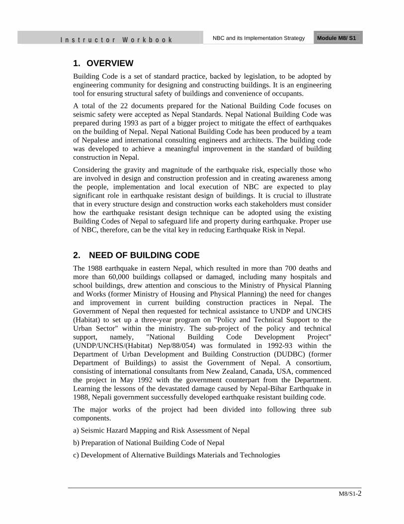
I n s t r u c t o r W o r k b o o k NBC and its Implementation Strategy Module M8/ S1
M8/S1-2
1. OVERVIEW Building Code is a set of standard practice, backed by legislation, to be adopted by engineering community for designing and constructing buildings. It is an engineering tool for ensuring structural safety of buildings and convenience of occupants.
A total of the 22 documents prepared for the National Building Code focuses on seismic safety were accepted as Nepal Standards. Nepal National Building Code was prepared during 1993 as part of a bigger project to mitigate the effect of earthquakes on the building of Nepal. Nepal National Building Code has been produced by a team of Nepalese and international consulting engineers and architects. The building code was developed to achieve a meaningful improvement in the standard of building construction in Nepal.
Considering the gravity and magnitude of the earthquake risk, especially those who are involved in design and construction profession and in creating awareness among the people, implementation and local execution of NBC are expected to play significant role in earthquake resistant design of buildings. It is crucial to illustrate that in every structure design and construction works each stakeholders must consider how the earthquake resistant design technique can be adopted using the existing Building Codes of Nepal to safeguard life and property during earthquake. Proper use of NBC, therefore, can be the vital key in reducing Earthquake Risk in Nepal.
2. NEED OF BUILDING CODE The 1988 earthquake in eastern Nepal, which resulted in more than 700 deaths and more than 60,000 buildings collapsed or damaged, including many hospitals and school buildings, drew attention and conscious to the Ministry of Physical Planning and Works (former Ministry of Housing and Physical Planning) the need for changes and improvement in current building construction practices in Nepal. The Government of Nepal then requested for technical assistance to UNDP and UNCHS (Habitat) to set up a three-year program on "Policy and Technical Support to the Urban Sector" within the ministry. The sub-project of the policy and technical support, namely, "National Building Code Development Project" (UNDP/UNCHS/(Habitat) Nep/88/054) was formulated in 1992-93 within the Department of Urban Development and Building Construction (DUDBC) (former Department of Buildings) to assist the Government of Nepal. A consortium, consisting of international consultants from New Zealand, Canada, USA, commenced the project in May 1992 with the government counterpart from the Department. Learning the lessons of the devastated damage caused by Nepal-Bihar Earthquake in 1988, Nepali government successfully developed earthquake resistant building code.
The major works of the project had been divided into following three sub components.
a) Seismic Hazard Mapping and Risk Assessment of Nepal
b) Preparation of National Building Code of Nepal
c) Development of Alternative Buildings Materials and Technologies
I n s t r u c t o r W o r k b o o k NBC and its Implementation Strategy Module M8/ S1
M8/S1-3
2.1 Situation before 1988 Earthquake
Nepal had no regulations of its own governing the design of buildings for strength. Designers had no trend of adopting and following rigorously regulations from other countries that might have been appropriate for Nepal. There was a serious lack of a professional approach to building design in Nepal. Apart from a small group of highly motivated people, the majority of apparently academically qualified engineers did not implement what many of them had been trained for. It appeared to be normal in both government and private organisations for nominally academically qualified personnel to be required to undertake design work without adequate work experience or supervision.
2.1.1 Prevalent Building Construction Practices It has repeatedly been mentioned in previous sessions that decisions pertaining to residential construction are made by owner-builders and/or masons, rather than by professionals. There were no building codes for strength being enforced in Nepal. There were some planning bylaws of local authorities which they attempted to enforce. Therefore, there was a building permit application process in place in some towns. Until then, Nepal had no regulations or documents of its own setting out either requirements or good practice for achieving satisfactory strength in buildings. A majority of residential structures had no rational design for strength at all. When trained engineers used to control the design of a structure, they normally made reference to a building code with which they were most familiar (i.e. used in the country of their training). The Indian Code appeared to be the most commonly used in Nepal. Engineers' consideration for earthquake loading when designing seemed to depend on the client's perception of the additional construction cost involved. It appeared that the average engineer did not forcefully counsel the reluctant client to accept earthquake resistant features. There were buildings in Nepal funded by international agencies without earthquake resistant designs. Even where earthquake loading was considered in design, many engineers were not implementing the most elementary of the detailed requirements of the Indian Code (e.g. with respect to details of bending of the reinforcing steel). If the full requirements of the Indian Code (which quotes some seismic loadings for Nepal) were adhered to, there would have been immediate improvement in the seismic resistance of new structures in Nepal. There were inherent dangers in taking an earthquake loading coefficient from the Indian Code without adequate understanding of fundamental aspects of earthquake resistant construction. It is possible, for instance, to adopt a philosophy accepting lower design loads as long as other details are correspondingly increased in reliability.
I n s t r u c t o r W o r k b o o k NBC and its Implementation Strategy Module M8/ S1
M8/S1-4
3. Philosophy The principal risks that lead to the development of the building code are that from earthquake. This risk is very great. This risk can be substantially lowered by intervention - much of it very simple and requiring commitment rather than the application of high technology which are expensive. The management plan for implementation of National Building Code indicates a strategy for achieving a lowering of the risk progressively over a period. Due to the socio-economic conditions and other political limits high level of safety and drastic change in the construction practice cannot be achieved immediately. It indicates incremental safety against zero safety. The existence of Nepal National Building Code gives an accessible minimum standard which all designers and other stakeholders can readily accept. The designs and personnel involved in the construction industry, therefore, should adopt this code sincerely so as to achieve a meaningful improvement in the standard of building construction in Nepal. The underlying philosophy is to reduce damage and loss of life from earthquakes. The strategy also defines ongoing activities required to ensure that higher levels of seismic safety are achieved for all buildings throughout Nepal which should be taken by different sectors of Nepalese society to raise the awareness of the consumer to the risks and the ways of mitigating them and at the same time preparing the designers, teachers, technicians and craftspeople for their roles in responding to the demands brought on by the increased awareness. Concurrent with the upgrading of professional expertise and craftsmen skills, administrative programmes and legislation are needed to implement and institutionalise the code. Improved seismic resistance of building structures shall be achieved through the implementation process, training of craftsmen and education of owner/builders. In addition the dissemination of the appropriate information to the people of Nepal however physically remote is the primary objective. We have to understand that the current Building Code however is not the final product; in fact it is the beginning of a process which needs timely upgrade to suit the condition of Nepal.
4. Implementation Mechanism The objective of developing the strategy is the implementation of the Building Code. Since the Building Code has been promulgated, it is preferable that it be enforced as much as possible in both rural and urban Nepal. Unless the enforcing agencies are sufficiently capable, it would be a futile exercise to try to enforce the Building Code. Of course a time based phasing will be required. Depending upon the capability of the local governments and extent and quality of assistance to them, this time could range from few years to many years. Whether or not the total Building Code is immediately enforced in all the municipalities and VDCs, many elements of the Building Code can be referenced by the building by-laws. A prerequisite for the integration of the strength component in the building permit process is the formation of by-laws which include this component. It is preferable to have a consistent set of regulations for the whole of Nepal that can be applied at different levels depending on their appropriateness to the local situation. It is the stated policy of the Government of Nepal to move towards the decentralising of power to local authorities. Two Acts namely the Building Act and Engineering Council
I n s t r u c t o r W o r k b o o k NBC and its Implementation Strategy Module M8/ S1
M8/S1-5
Act rightly and pragmatically address the matters by the central government in conjunction with architects/engineers and local authorities. The efforts for implementation of building codes are consisted with two components; i) Massive training to the Technicians about the code, and ii) dissemination and public awareness raising programme about earthquake resistance building construction. The mechanism required for setting up of a technical support unit by central government as a means of providing assistance to the Engineering Council to achieve its charter and to the local authorities to cover their inevitable deficiencies in technical capabilities in the implementation of their building regulations. It is appropriate that the development, promulgation and training for such regulations be undertaken by the central government in concern with local authorities and with private sector.
4.1 Building Act
The main objective of the Building Act, 1994 is to make the necessary provisions for formulating and implementing the Building Code and regulating building construction in order to keep buildings safe from natural calamity like earthquake, fire etc as far as possible. The Building Act is also the mechanism by which local authorities are enabled and encouraged to implement the regulations at levels appropriate to their particular situation.
4.2 Engineering Council Act
Engineering Council Act set up a cooperative process between the central government and the existing professional groups to maintain a register of competent designers, entry being by a system of peer-review. The main objective of the Engineers Council Act, 1994 is to manage the Engineers Council in order to determine the qualification required for a person to be registered as an Engineer, to register the name of qualified person as an Engineer and to protect and promote their right and interest and to make necessary provisions relating to their Code of conduct. The Engineering Council Act allows for a partnership between Government of Nepal and the engineering professional bodies to set up and administer a register of engineers who have reached a satisfactory level of competence. The necessary provisions have been made to ensure that older present practitioners are not disenfranchised by the proposed Act. The requirement for ethical conduct to be maintained is provisioned in the Act. This Act provides the means for local authorities to accept self-certification of the building permit applications for designs requiring engineered designs in accordance with whatever Codes they adopt. This is a practical solution to the difficulty local authorities have, in building up the necessary in-house expertise to check such applications. The promulgation of the Engineering Council Act is a critical requirement for the implementation of the National Building Code. No amount of technical regulation can
I n s t r u c t o r W o r k b o o k NBC and its Implementation Strategy Module M8/ S1
M8/S1-6
contribute as much to the implementation as the fostering of a more professional attitude amongst and by the practising engineers in Nepal.
4.3 Implementation Plan
A Management Plan for the Implementation of a National Building Code for Nepal was prepared during 1993 as part of technical assistance of the HMGN/ UNDP/ UNCHS (Habitat) project NEP/88/054. For change to come in there has to be a desire by the public. Both short and long-term aspects of this plan therefore should address matters of education about the benefits that a better-regulated building industry would bring about. There is a great deal of training and development required to raise the standards of all those involved in the building process to a level sufficient to support the aims of the National Building Code. In particular, the teaching of the benefits of mitigating the significant earthquake hazard in Nepal should be concentrated on. There is also a desperate need in Nepal for better access to technical literature and historical information on building. The three phases of the plan are:
1) Short term (0-3 years) 2) Mid term (3-5 years) 3) Long term (6-15 years)
4.3.1 Short Term Plan
The short term educational and training period aimed to increase awareness of seismic resistance and develop the expertise among professionals and craftsmen to design and build safer buildings. This enhanced awareness and its acceptance was critical. More focus was given on standards for seismic resistant construction for most important structures which are either needed immediately after a disaster, such as hospitals and clinics or where the chances of life loss are high, such as schools. High priority structures included:
· Hospitals
· Health clinics
· Emergency relief storage
· Schools
· Other government constructions
The higher standards used for these buildings would result in good examples which could be used as the primary tool to increase awareness of seismic resistance among owner builders throughout the country. Construction of such examples would also be an important way to help improve the skills of local craftspeople. While the emphasis to this point has been on shorter-term measures applied through regulation, substantial improvements nation-wide in building safety is only going to take place when they become driven by the awareness of the risk by the consumers.
I n s t r u c t o r W o r k b o o k NBC and its Implementation Strategy Module M8/ S1
M8/S1-7
The implementation of building regulations in municipalities in the short-term had to resort to accepting self certification by the designers of submitted designs of engineered buildings to meet their regulations.
4.3.2 Mid Term Plan
The main objective is increased expertise to comply with the Code and guidelines for safer construction. During the short term period, it is assumed that the awareness of seismic resistance has been heightened, especially throughout the Kathmandu Valley. These efforts need to be continued and strengthened during the mid-term. In addition, the short-term educational efforts will have assisted professionals, technicians and craftsmen to have achieved higher levels of expertise, and during the mid-term this expertise can be required through implementation of certification and adoption of selected portions of the code. Key activities would be continuation of construction of additional buildings which comply with the Mandatory Rules of Thumb and provide documentation of the construction process.
4.3.3 Long term Plan
A long-term plan is for bringing about change to the existing practices through training at all levels. The main objective is to institutionalise the concept of seismic-resistant construction by fully adopting the code. In rural areas, to ensure that there are a sufficient number of buildings to demonstrate seismic-resistant construction using local materials and building techniques. Key activities remain to review and evaluate activities undertaken during the Short and Mid-Term Planning periods. Evaluation of activities will identify the ones which were the most effective and those which should be discontinued. The need for additional activities will also be identified.
The longer-term benefits will be wide and very significant. Institutions training Nepalese under-graduate engineers will need to produce graduates with appropriate academic competency to maintain their market-share. Career paths will become linked to the attainment of satisfactory supervised work experience after graduation. International recognition of Nepalese qualifications will follow. The profession will become more self motivated to contribute to the development of technical standards and the upholding of ethical standards as their status grows in the eyes of the public.
The implementation strategy addresses:
· What institutional steps should be taken to disseminate information?
· Who best should disseminate the information?
· What information should be disseminated - in what physical form?
· How to inform public that a building code has been developed? The dissemination program must communicate with many different types of people who have different levels of technical expertise. The educational dissemination program must, therefore, be available in both print and visual medial in both the urban and rural areas. This multi-media form of communication is especially critical because of the high illiteracy rate compounded by the very low level of expertise with respect to issues pertaining to seismic resistance among all sectors of the construction industry (among
I n s t r u c t o r W o r k b o o k NBC and its Implementation Strategy Module M8/ S1
M8/S1-8
professionals, technicians, craftsmen, etc.). Each form for dissemination will utilize the materials prepared by the project in different combinations.
5. Components of Building Code NBC categorizes design and construction of buildings into four types according to their level of sophistication.
• International state-of-the-art • Professionally engineered structures • Buildings of restricted size designed to simple Rules-of-Thumb • Remote rural buildings where control is impractical
Each of the four levels is discussed below:
i) International State-of-the-Art
Because the major thrust of the code is aimed at the typical and most common buildings currently being erected in Nepal, it deliberately does not suggest as being practical for everyday consideration the sophisticated design philosophies and analytical techniques that are appearing in the codes of more wealthy countries.
However, it is important that both Nepalese engineers and overseas consultants who can produce such designs in a routine fashion and can ensure that their designs can be built to the corresponding standards should not be prevented from doing so. Moreover, these structures should be seen to be meeting the Nepalese requirements with respect to minimum load and configuration/height. There is then no reason for any designer to argue a case for ignoring the Nepal regulations in their entirety. A section of the code describes some of the philosophy behind the selection of loads (in particular, the earthquake ones) and allows the sophisticated designer to build up a design philosophy consistent with, and encompassing, the basic requirements. The responsibility will be on the designer to prove that the Nepal Code requirements have been met and/or exceeded.
ii) Professionally Engineered Structures
These are the standard code requirements that all professionally qualified engineers will recognise and follow when designing structures in Nepal. It will cover all major structures such as hospitals, meeting halls, factories, warehouses, multi-storey buildings and larger residential buildings. Materials, analysis and design, construction safety and site considerations are all covered.
iii) Mandatory Rules-of-Thumb
This section recognises that it is not practical at present to insist that all small buildings be designed by professionals. Therefore, for classes of buildings not exceeding certain simple criteria as to height, number of storeys and floor area, mandatory rules-of-thumb is provided. The explanatory documents are such that an experienced overseer or mason should be able to understand them and present sufficient details at the time of permit
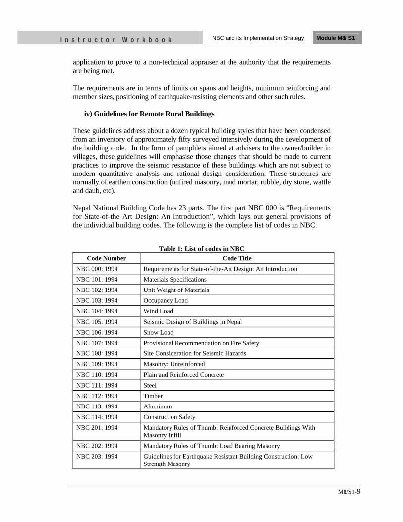
I n s t r u c t o r W o r k b o o k NBC and its Implementation Strategy Module M8/ S1
M8/S1-9
application to prove to a non-technical appraiser at the authority that the requirements are being met. The requirements are in terms of limits on spans and heights, minimum reinforcing and member sizes, positioning of earthquake-resisting elements and other such rules.
iv) Guidelines for Remote Rural Buildings These guidelines address about a dozen typical building styles that have been condensed from an inventory of approximately fifty surveyed intensively during the development of the building code. In the form of pamphlets aimed at advisers to the owner/builder in villages, these guidelines will emphasise those changes that should be made to current practices to improve the seismic resistance of these buildings which are not subject to modern quantitative analysis and rational design consideration. These structures are normally of earthen construction (unfired masonry, mud mortar, rubble, dry stone, wattle and daub, etc). Nepal National Building Code has 23 parts. The first part NBC 000 is “Requirements for State-of-the Art Design: An Introduction”, which lays out general provisions of the individual building codes. The following is the complete list of codes in NBC.
Table 1: List of codes in NBC Code Number Code Title
NBC 000: 1994 Requirements for State-of-the-Art Design: An Introduction NBC 101: 1994 Materials Specifications NBC 102: 1994 Unit Weight of Materials NBC 103: 1994 Occupancy Load NBC 104: 1994 Wind Load NBC 105: 1994 Seismic Design of Buildings in Nepal NBC 106: 1994 Snow Load NBC 107: 1994 Provisional Recommendation on Fire Safety NBC 108: 1994 Site Consideration for Seismic Hazards NBC 109: 1994 Masonry: Unreinforced NBC 110: 1994 Plain and Reinforced Concrete NBC 111: 1994 Steel NBC 112: 1994 Timber NBC 113: 1994 Aluminum NBC 114: 1994 Construction Safety NBC 201: 1994 Mandatory Rules of Thumb: Reinforced Concrete Buildings With
Masonry Infill NBC 202: 1994 Mandatory Rules of Thumb: Load Bearing Masonry NBC 203: 1994 Guidelines for Earthquake Resistant Building Construction: Low
Strength Masonry
I n s t r u c t o r W o r k b o o k NBC and its Implementation Strategy Module M8/ S1
M8/S1-10
NBC 204: 1994 Guidelines for Earthquake Resistant Building Construction: Earthen Building (EB)
NBC 205: 1994 Mandatory Rules of Thumb: Reinforced Concrete Buildings Without Masonry Infill
NBC 206: 2003 Architectural Design Requirements NBC 207: 2003 Electrical Design Requirements for (Public Buildings) NBC 208: 2003 Sanitary and Plumbing Design Requirements
UNIT TEST 1) Discuss the Philosophy of building code implementation in Nepal
• ….
2) List two existing acts related to building code in Nepal
• … • ….
3) List four Components of Building Code
• ... • ....
• ....
• ....
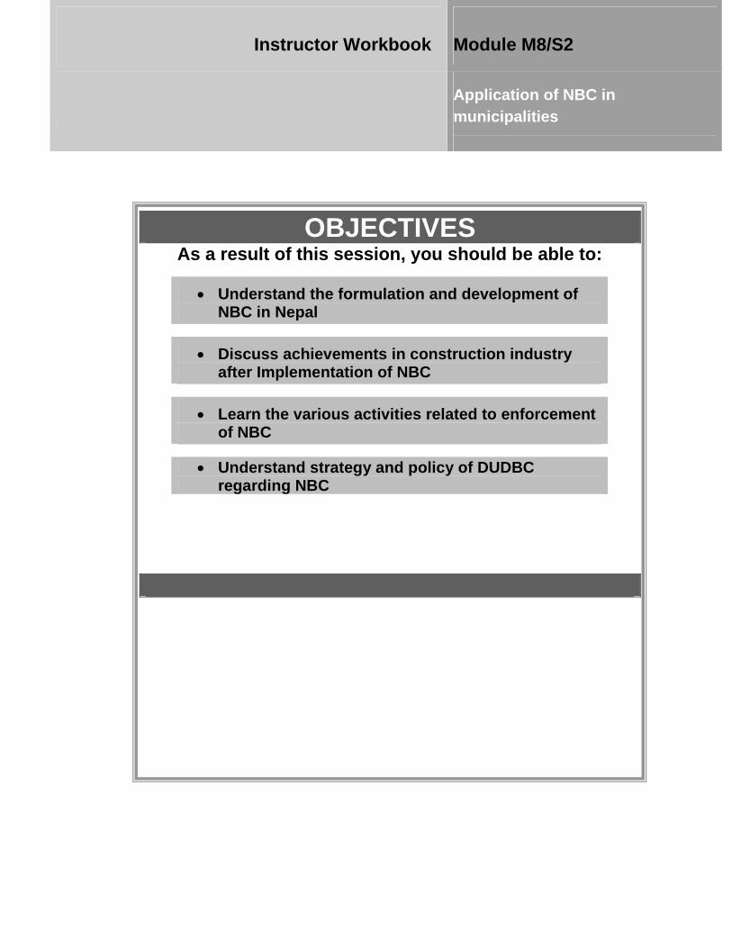
OBJECTIVES As a result of this session, you should be able to:
•• UUnnddeerrssttaanndd tthhee ffoorrmmuullaattiioonn aanndd ddeevveellooppmmeenntt ooff NNBBCC iinn NNeeppaall
• DDiissccuussss aacchhiieevveemmeennttss iinn ccoonnssttrruuccttiioonn iinndduussttrryy aafftteerr IImmpplleemmeennttaattiioonn ooff NNBBCC
• LLeeaarrnn tthhee vvaarriioouuss aaccttiivviittiieess rreellaatteedd ttoo eennffoorrcceemmeenntt ooff NNBBCC
•• UUnnddeerrssttaanndd ssttrraatteeggyy aanndd ppoolliiccyy ooff DDUUDDBBCC rreeggaarrddiinngg NNBBCC
Instructor Workbook Module M8/S2
Application of NBC in municipalities
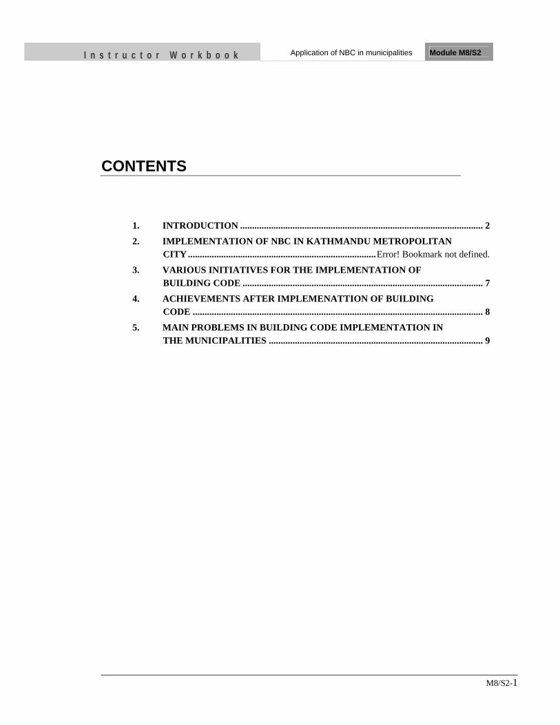
I n s t r u c t o r W o r k b o o k Application of NBC in municipalities Module M8/S2
M8/S2-1
CONTENTS
1. INTRODUCTION ...................................................................................................... 2
2. IMPLEMENTATION OF NBC IN KATHMANDU METROPOLITAN CITY ............................................................................... Error! Bookmark not defined.
3. VARIOUS INITIATIVES FOR THE IMPLEMENTATION OF BUILDING CODE ..................................................................................................... 7
4. ACHIEVEMENTS AFTER IMPLEMENATTION OF BUILDING CODE .......................................................................................................................... 8
5. MAIN PROBLEMS IN BUILDING CODE IMPLEMENTATION IN THE MUNICIPALITIES .......................................................................................... 9
I n s t r u c t o r W o r k b o o k Application of NBC in municipalities Module M8/S2
M8/S2-2
1. INTRODUCTION The Department of Urban Development and Building Construction (DUDBC) under the Ministry of Physical Planning and Works (MPPW) developed Nepal National Building Code (NBC) in 1993 with the assistance of the United Nations Development Program and United Nations Centre for Human Settlement (UN-HABITAT). In 2003, the Council of Ministers decreed that the stipulations of the National Building Code should be made obligatory for all government-building constructions. It also urged the municipal authorities to strengthen the current building permit process so that code compliance will be mandatory for all new constructions in urban areas. For the successful enactment of NBC, the Department set different strategies, some of which are as follows: a) DUDBC’s role and initiative: DUDBC acts as manager, facilitator and policy
maker b) Coordination and corporation of other institutions: DUDBC coordinate with the
Curriculum Branch of Universities to endorse NBC in the engineering courses. As privately owned buildings occupy more than 90% of total buildings of the country, wider and wider awareness to all people is a prerequisite factor. The Ministry in 2006 published a notification in the Gazette which made the implementation of NBC mandatory in all Municipalities and some Village Development Committees (VDCs) in Nepal. Implementation of building code lagged behind until the amendment in the Building Act 2055 (1998). The amendment came into effect in BS 2064 (2007) which paved the way for municipalities to take the responsibilities. R Building Code Implementation in 2. TYPICAL BUILDING PERMIT PROCESS
2.1.1 Building Permit Process by Local Authorities It is of interest to understand that there was a building permit process without any building by-laws. Section 9, clause 54 of the Municipality Act, 2048 BS stated that a building permit should be taken from the municipality for new construction, reconstruction, additions and alterations, face lifting, etc. It was also mentioned that an application for a permit should be submitted in the format prescribed by the municipality. Hence, the normal practice in applying for a building permit was to submit the application in the prescribed format which varies from municipality to municipality. Application for a permit is limited to individuals.
The Act remained silent with respect to the issuing of permits to institutions. Clause 58 of the Act empowered then mayor to issue special building permits for special designs based on the physical plan of the town and by-laws formulated within the framework of existing legal provisions. Similarly, clause 83 of the Act empowered the municipality to formulate building by-laws. All the municipalities seemed to have under-utilized the Municipality Act, 2048 so far as by-laws for the issuing of permits
I n s t r u c t o r W o r k b o o k Application of NBC in municipalities Module M8/S2
M8/S2-3
were concerned or, rather, the formulation of an appropriate by-law was concerned. The provisions in clauses 54 and 83 of the Municipality Act made it possible for individual municipalities to prescribe their own building by-laws and permit application to suit their own requirements. As the procedure to issue the building permit was concerned, clause 56 of the Municipality Act prescribed a set of procedures which all the municipalities were to follow in common.
90 percent of the country's population was rural; most people used to live in areas administered by Village Development Committees (VDC). A VDC did not have the right to issue a building permit. In other words, no building permit was required if anyone wanted to build outside the municipal boundaries, irrespective of the level of construction, i.e. whether it was a professionally engineered or a rural building. However, section 12, clause 59/2 of the Village Development Committee Act 2048 empowered VDC's to formulate regulations for its operation within the framework of the Act and these might be enacted after approval by the District Development Committee.
The overall existed situation, regarding the building permit procedures and the building by-laws, suggested a few important actions required to be taken. These were:
• Formulation of appropriate by-laws for municipalities and Town Development Committees, dealing with the strength aspect of the building where by-laws were not yet formulated or by-laws were in a rudimentary form.
• Revision of by-laws to accommodate the strength component in municipalities
where by-laws had already been formulated.
• Making a building permit mandatory for all public and private building structures and at least for institutions (Government and non-government).
• Introduction of a building permit system in Village Development Committees.
A three stages building permit process is mainly being practiced in Nepal. First stage starts with application by owner and ends with Temporary Permit for construction up to Plinth Level. In the second stage, the house owner applies for permanent permit and after the field verification, if the construction is found to be in conformity with initial permit in accordance with the by-laws and NBC, permanent building permit is issued. Finally, field checking is conducted at different stages of construction and the Completion Certificate is issued to the owner. The three-stage implementation process, as shown in following figure is a standard approach for the effective implementation of NBC.
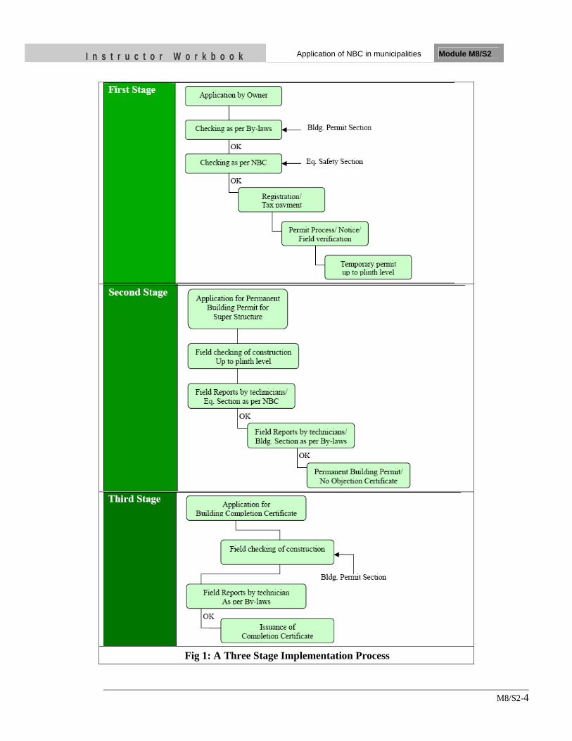
I n s t r u c t o r W o r k b o o k Application of NBC in municipalities Module M8/S2
M8/S2-4
Fig 1: A Three Stage Implementation Process
I n s t r u c t o r W o r k b o o k Application of NBC in municipalities Module M8/S2
M8/S2-5
Lalitpur Sub-Metropolitan City (LSMC) announced the implementation of Nepal National Building Code (NBC) in building permit process on the occasion of Earthquake Safety Day on 16th January, 2003 and became the first and leading municipality in Nepal to implement NBC. The decision was historic in the sense that it not only encouraged the government to enforce NBC but also guided other municipalities on the necessity of building code implementation. At the beginning, implementation of NBC was carried out by Technical Cell (Group of Engineers from Municipality, DUDBC and other organizations). Dharan Municipality followed it in 2007 and recently Hetauda Municipality did so on the occasion of Earthquake Safety Day in 2011. It is encouraging to note that Birendranagar Municipality has declared 50% concession on permit charges if the design is in accordance to NBC. It is expected that other municipalities take similar steps to implement NBC in the future. Kathmandu Metropolitan City (KMC) started implementing building code from August 21, 2005 for the construction of buildings within the city, two years later the implementation of the building code in the construction of government buildings. In October 2005 a National Building Code Implementation Committee was set up within KMC. It comprised six specialists who acted on a voluntary basis. This committee along with the Building Permit Section is in charge of building code implementation and enforcement at KMC. Nation-wide requirements of the building code categories are also being enforced at KMC:
• International state of the art is applied for buildings having 6 floors and above, drawings and calculations need to be presented, to the established Review Committee. Owner and constructor bear the responsibility.
• Professional engineered building category is applied to those structures having stories between 3-6. Basic blue prints need to be submitted.
• Buildings under 3 floors, either design properly or follow mandatory rule of thumb, guidelines are available
In addition, other procedures for design and field control have been established, for example:
• Three stages to issue construction and habitability permits: foundation level, upper structure completion and final inspection.
• Minimum size of the reinforced concrete columns has been set as 230X300 mm as an earthquake safety measure
2.1.2 CHALLENGES
The progress of application of NBC in municipalities cannot be assumed satisfactory and as expected. There are still many things to be done; many systems and processes to be formulated and developed. LSMC for example is still going through many technical & management complications and problems. Technical problems are related to Design /Drawings and field implementation and managerial problems are related to institutional set and social/practical problems.
Though there is considerable improvement, there still exist some problems in building construction practice. Some of the professional designers are following the building
I n s t r u c t o r W o r k b o o k Application of NBC in municipalities Module M8/S2
M8/S2-6
code seriously whilst most of the designers are not. Although there are provisions for submitting structural details for buildings more than three stories in height or more than 1000 SF of plinth area, structural engineers take this as just a formality and limited to some typical details, which actually is not a structural design. Not any checking system, norms or a mechanism has been developed for structural designs of submitted building drawings although there is clear mention in Current building bylaws that all buildings should be designed in accordance with Nepal National Building Code. Similarly, desired quality has not yet maintained in construction field in overall. The effort to involve designers in supervision has been limited / constrained to paper only. More than 90% of buildings have been constructed without supervision of technicians. Contractor and mason are not aware about the quality of construction materials and earthquake technologies.
2.1.3 LESSONS LEARNT
Lalitpur is one of the five municipalities comprising the Kathmandu Valley. This small city has taken a very successful and innovative approach to motivate different actors of the construction process, as well as end users, on the need to follow the minimum building regulations set forth by the building code, as a good mitigation measure and as a way to protect live and property in their city. To enhance the construction trend of safe and quality structures urgent need has been felt to systemize and strengthen the implementation part of national building code. For that purpose the earthquake safety section should be established and strengthened and full support should be given to its activities and programs in future to make them more sustainable and more reliable. Considering all the problems, factors and challenges and to find out better solutions, better strategies on building code application, special priority/attention should be given to the activities of Earthquake Safety Section and separate budget should be allocated in municipal annual program. As Nepal lies in Earthquake prone area and is very sensitive from earthquake point of view, we should take serious steps and think seriously on the forecasts and announcement made by seismologists. The activities of Earthquake Safety Section should not be constrained/limited to only building permit processes. Its scope of work should be widened to greater extent. New programs/systems should be launched at grass root level. There should be some scheduled regular activities related to earthquake technologies in each ward. The experience of building code implementation in Nepal demonstrates that legal mechanism alone is not sufficient for effective implementation of NBC. Although the legal provision makes all municipalities and some Village Development Committees (VDCs) responsible to implement the code, it has achieved limited success. One of the decisive factors in effective implementation of NBC is capacity of the municipalities. Another equally important aspect is political will of the municipal authorities to start the process. Awareness on earthquake safety among municipal authorities and general public can create conducive environment for making a political decision to implement NBC. The basic key component for effective implementation of Building Code is:
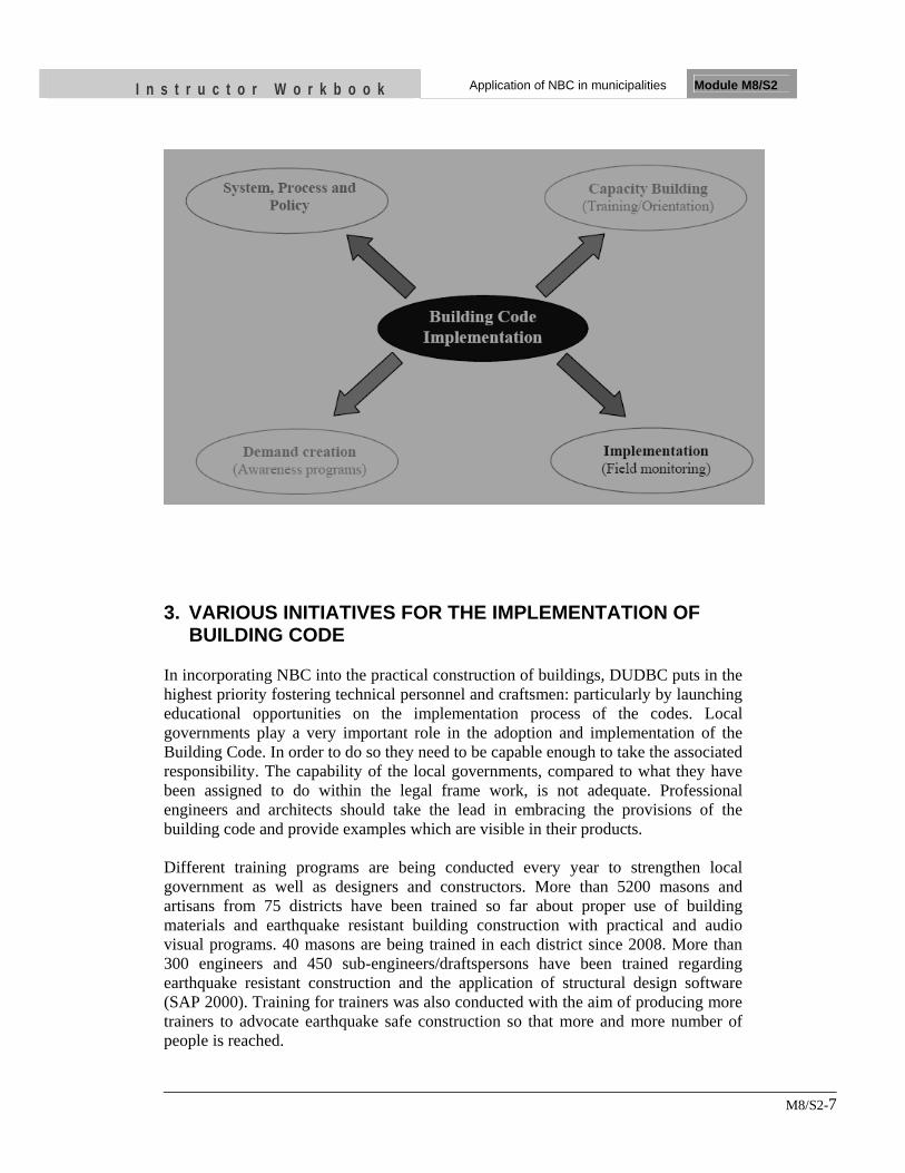
I n s t r u c t o r W o r k b o o k Application of NBC in municipalities Module M8/S2
M8/S2-7
3. VARIOUS INITIATIVES FOR THE IMPLEMENTATION OF
BUILDING CODE In incorporating NBC into the practical construction of buildings, DUDBC puts in the highest priority fostering technical personnel and craftsmen: particularly by launching educational opportunities on the implementation process of the codes. Local governments play a very important role in the adoption and implementation of the Building Code. In order to do so they need to be capable enough to take the associated responsibility. The capability of the local governments, compared to what they have been assigned to do within the legal frame work, is not adequate. Professional engineers and architects should take the lead in embracing the provisions of the building code and provide examples which are visible in their products. Different training programs are being conducted every year to strengthen local government as well as designers and constructors. More than 5200 masons and artisans from 75 districts have been trained so far about proper use of building materials and earthquake resistant building construction with practical and audio visual programs. 40 masons are being trained in each district since 2008. More than 300 engineers and 450 sub-engineers/draftspersons have been trained regarding earthquake resistant construction and the application of structural design software (SAP 2000). Training for trainers was also conducted with the aim of producing more trainers to advocate earthquake safe construction so that more and more number of people is reached.
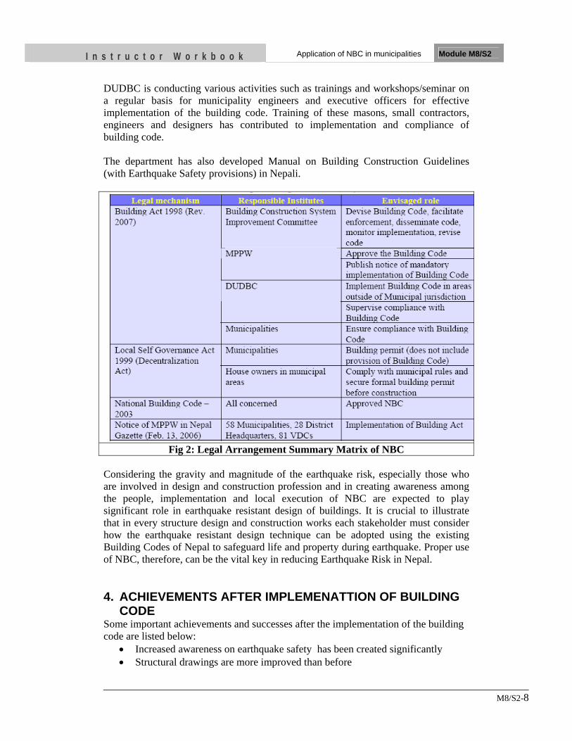
I n s t r u c t o r W o r k b o o k Application of NBC in municipalities Module M8/S2
M8/S2-8
DUDBC is conducting various activities such as trainings and workshops/seminar on a regular basis for municipality engineers and executive officers for effective implementation of the building code. Training of these masons, small contractors, engineers and designers has contributed to implementation and compliance of building code. The department has also developed Manual on Building Construction Guidelines (with Earthquake Safety provisions) in Nepali.
Fig 2: Legal Arrangement Summary Matrix of NBC Considering the gravity and magnitude of the earthquake risk, especially those who are involved in design and construction profession and in creating awareness among the people, implementation and local execution of NBC are expected to play significant role in earthquake resistant design of buildings. It is crucial to illustrate that in every structure design and construction works each stakeholder must consider how the earthquake resistant design technique can be adopted using the existing Building Codes of Nepal to safeguard life and property during earthquake. Proper use of NBC, therefore, can be the vital key in reducing Earthquake Risk in Nepal. 4. ACHIEVEMENTS AFTER IMPLEMENATTION OF BUILDING
CODE Some important achievements and successes after the implementation of the building code are listed below:
• Increased awareness on earthquake safety has been created significantly • Structural drawings are more improved than before
I n s t r u c t o r W o r k b o o k Application of NBC in municipalities Module M8/S2
M8/S2-9
• Designers are found more conscious in structural designs than before • Owners are more aware in applying structural design/drawings • Construction of the buildings as per NBC in construction field. • International and national recognition of the municipality eg. Lalitpur Sub-
metropolitan city 5. MAIN PROBLEMS IN BUILDING CODE IMPLEMENTATION
IN THE MUNICIPALITIES Main problems facing difficulty in the implementation of building code are highlighted below:
• Lack of information about the Building Code • Lack of information about earthquake safety • Lack of resource in local Authority • Lack of sufficient trainings to the stakeholders such as the municipality staff,
designers, constructors • Need of Revision of Building Code • Need of amendment of Building Act for effective implementation • Practical implementation of building code limited to few municipalities • Lack of monitoring and field visits due to inadequate human resource. • Unethical practice of designers • Compromise of quality of construction and compliance of building code with
the cheaper cost (mostly by the use of unskilled labor)
I n s t r u c t o r W o r k b o o k Application of NBC in municipalities Module M8/S2
M8/S2-10
UNIT TEST 1) When was the building code formally announced to be effective in Nepal
and KMC
• … • …
2) List three problems in implementing building code in Nepal
• .. • … • ….
3) List three main achievements after the implementation of building code
• ... • ... • ...
OBJECTIVES As a result of this session, you should be able to:
•• IIddeennttiiffyy ffoouurr ffaaccttoorrss aaffffeeccttiinngg tthhee qquuaalliittyy ooff ccoonnssttrruuccttiioonn
• DDiissccuussss tthhee sseelleeccttiioonn ooff ggoooodd bbuuiillddiinngg mmaatteerriiaall
• DDeessccrriibbee ggoooodd aanndd bbaadd pprraaccttiicceess ooff wwoorrkkmmaannsshhiipp
Instructor Workbook Module M8/S4
Quality Control in Construction
I n s t r u c t o r W o r k b o o k Quality Control in Construction Module M8/ S4
M8/S4-1
CONTENTS
1. INTRODUCTION ....................................................................................................................... 2
2. DESIGN........................................................................................................................................ 2
2.1 Quality of Design .............................................................................................................. 2
2.2 Work and Material Specification ...................................................................................... 4
2.3 Drawings and Detailing ..................................................................................................... 5
3. MATERIAL QUALITY ............................................................................................................. 5
3.1 Cement ............................................................................................................................... 5
3.2 Aggregate ........................................................................................................................... 6
3.3 Water .................................................................................................................................. 7
3.4 Bricks ................................................................................................................................. 7
3.5 Stone .................................................................................................................................. 7
3.6 Steel Reinforcement .......................................................................................................... 7
3.7 Timber ................................................................................................................................ 8
4. Workmanship .............................................................................................................................. 8
4.1 Masonry Wall Construction .............................................................................................. 9
4.1.1 Mortar Preparation .............................................................................................. 9
4.1.2 Laying of Bricks .................................................................................................. 9
4.2 Reinforced Concrete Construction .................................................................................... 9
4.2.1 Measurement and Proportioning of Concrete Materials .................................. 10
4.2.2 Measurement of Consistency ............................................................................ 10
4.2.3 Concrete Mixing ................................................................................................ 10
4.2.4 Placing of Concrete ........................................................................................... 12
Preparation for Placing Concrete .................................................................................... 12
Placing Concrete .............................................................................................................. 12
4.2.5 Vibration ............................................................................................................ 13
Appearance ...................................................................................................................... 13
4.2.6 Protection and Curing of Concrete ................................................................... 14
4.2.7 Cover of Concrete ............................................................................................. 15
4.2.8 Formwork .......................................................................................................... 15
I n s t r u c t o r W o r k b o o k Quality Control in Construction Module M8/ S4
M8/S4-2
1. INTRODUCTION Quality control in construction typically involves ensuring compliance with minimum standards of material and workmanship. The minimum standards are contained in the specifications. Quality of the construction must be maintained throughout the duration of the project in order for a project to be completed successfully. Quality requirements should be clear and verifiable, so that all parties in the project can understand the requirements. Quality control represents increasingly important concerns for any construction project. Defects or failures in constructed facilities can result in very large costs. Even with minor defects, re-construction may be required and facility operations impaired. Increased costs and delays are the result. In the worst case, failures may cause personal injuries or fatalities. Accidents during the construction process can similarly result in personal injuries and large costs. Indirect costs of insurance, inspection and regulation are increasing rapidly due to these increased direct costs. Investigations of buildings damaged by earthquakes often cite construction flaws, the lack of adherence to minimum code standards, or failure to follow approved plans and specifications as major causes of damage. The following are the factors that affect the quality of work,
1. Design 2. Material Quality 3. Workmanship 4. Project Period
2. DESIGN The most important decisions regarding the quality of a completed building structure are made during the design and planning stages rather than during construction. It is during these preliminary stages that component configurations, material specifications and functional performance are decided. The structural engineer and architect are responsible for choosing a structural system and preparing the design documents. A good structural design is the starting point to achieve satisfactory earthquake performance Quality control during construction consists largely of insuring conformance to these original designs and planning decisions. Building's ability to withstand gravity and earthquake forces highly depends on appropriate structural design, adequate design reviews and understanding of the building code. As most design professionals should know failure of majority of buildings in past earthquake is due to lack of understanding and appreciating the importance of following standards and codes.
2.1 Quality of Design
It is important that the designer identifies the tasks which are necessary to assure quality and the level of safety for the occupants of the building. It is important to take
I n s t r u c t o r W o r k b o o k Quality Control in Construction Module M8/ S4
M8/S4-3
necessary precautions in the site selection, planning and design of structures so that they are safe. The designer should strictly follow the codes and guidelines which are intended for the better performance of the building in any type of loading that is desired. The designer shall focus on the basic design requirements such as performance objective of the building, design load, structural system, configuration, functional requirement and also the building cost. These criteria have to set forth clearly before designing the particular building to ensure the proper quality of any construction project. Based on which the designer starts analysis and design of the building meeting all the design requirements. While conformance to existing design decisions is the primary focus of quality control, there are exceptions to this rule. First, unforeseen circumstances, incorrect design decisions or changes desired by an owner in the facility function may require re-evaluation of design decisions during the course of construction. While these changes may be motivated by the concern for quality, they represent occasions for re-design with all the attendant objectives and constraints. As a second case, some designs rely upon informed and appropriate decision making during the construction process itself. For example, some designers make decisions about the amount of piling required at different locations based upon observation of soil conditions during the excavation for foundation. Since such decisions are based on better information concerning actual site conditions, the facility design may be more cost effective as a result. The design professional should make observation of construction site for general conformance to the conditions assumed during design, and for general conformance to the approved construction documents. Structural monitoring should be made at various significant stages of construction and at completion of the structural system To establish a formal Quality Assurance programme, the procedure below can be followed (O’Brien, 1989)
1 Develop/Review the project procedure manual. This document, prepared under direction of the project manager, describes the requirements related to the performance of the project.
2 Develop/Review the written project programme. This describes the owner’s
requirements, design parameters, codes, standards, materials, design concepts and constructability.
3 Standard procedures should be established to define the checks to be carried
out, to identify the checker and to determine approval requirements. It is necessary to check the design calculations, drawings, specifications, estimates of construction cost and relevant construction documents. The checking should be performed by qualified individual/third party not directly involved in the design or supervision of the work.
4 Review coordination of the work performed by various disciplines. Many
projects contain drawings and other documents from several discipline such as civil, structural, heating-ventilation-air-conditioning (HVAC) and
I n s t r u c t o r W o r k b o o k Quality Control in Construction Module M8/ S4
M8/S4-4
electrical. A procedure should be established for checking the document from each discipline and integrating them as a single set of construction documents to achieve the desired result.
2.2 Work and Material Specification
Specifications of quality work are an important feature of facility designs. Specifications of required quality and components represent part of the necessary documentation to describe a facility. Specifications are an important feature of any construction to avoid construction flaws. Well-written specifications are essential for the efficient completion of a project. The specifications inform the contractor of the work to be performed, the conditions and restrictions for the work, the expected quality of the work, and the manner in which the work will be measured for payment. Construction specifications normally consist of a series of instructions or prohibitions for specific operations. A specification is a type of a standard which is often referenced by a contract or procurement document. It provides the necessary details about the specific requirements.
With the attention to conformance as the measure of quality during the construction process, the specification of quality requirements in the design and contract documentation becomes extremely important. Quality requirements should be clear and verifiable, so that all parties in the project can understand the requirements for conformance.
A technical specification may be developed privately, for example by a corporation, regulatory body etc: It is usually under the umbrella of a quality management system. They can also be developed by standards organizations which often have more diverse input and usually develop voluntary standards: these might become mandatory if adopted by a government, business contract, etc.
General specifications of work quality are available in numerous fields and are issued in publications of organizations such as the American Society for Testing and Materials (ASTM), Indian Standards (IS) etc. Distinct specifications are formalized for particular types of construction activities, such as welding standards issued by the American Welding Society, or for particular facility types, such as the Standard Specifications for Highway Bridges issued by the American Association of State Highway and Transportation Officials. These general specifications must be modified to reflect local conditions, policies, available materials, local regulations and other special circumstances. The qualities of well-written specifications are as follows.
- Clear, concise, and technically correct - Do not use ambiguous words that could lead to misinterpretation. - Written using simple words in short, easy to understand sentences. - Use technically correct terms, not slang or “field” words. - Avoid conflicting requirements - Do not repeat requirements stated elsewhere in the contract.
I n s t r u c t o r W o r k b o o k Quality Control in Construction Module M8/ S4
M8/S4-5
- State construction requirements sequentially. - Avoid the use of awkward phrases such as “and/or”
2.3 Drawings and Detailing
A working drawing is the final construction drawing, produced as part of the design process. Once suitable concept sketches are created, the next step is to make working drawings that are proportionally accurate but at a reduced scale. They are used to refine design details and to determine specific dimensions of the various components.
The detail working drawings shall be produced to facilitate the construction process. A working drawing is a type of technical drawing, which is part of the documentation needed to build an engineering product or architecture. Typically in architecture these could include civil drawings, architectural drawings, structural drawings, mechanical drawings, electrical drawings, and plumbing drawings. The working drawing should be precise, drawn to a scale and complete. Dimensions are added so that any person using the working drawing can carry the construction work without any mistake. This improves the construction quality in case the things are clear and precise beforehand.
Other construction documents such as quality plans, manuals, specifications, reports and records enable proper implementation of the project.
3. MATERIAL QUALITY The materials to be used in the works shall be of the qualities and kinds specified. Selection and use of appropriate and good quality materials is a prerequisite for successful construction. Materials shall be delivered to the works before it is required for use in work. Delivery shall be made sufficiently in advance of constructional requirements to enable samples to be selected, tested and approved by the Engineer. No material shall be used in the Works until approved. Materials failing to comply with the approved samples and specification shall be removed from the site at the Contractor's cost.
3.1 Cement
Cement is a binder, a substance which sets and hardens independently, and can bind other materials together. Cements used in construction are characterized as hydraulic or non-hydraulic. The most important use of cement is the production of mortar and concrete—the bonding of natural or artificial aggregates to form a strong building material which is durable in the face of normal environmental effects.
I n s t r u c t o r W o r k b o o k Quality Control in Construction Module M8/ S4
M8/S4-6
The cement may be of various types such as Ordinary Portland Cement, low heat cement, rapid hardening cement, expansive cement, white cement etc. The cement shall be of approved brand and manufacture and shall comply in all respects with the specification of relevant building standard. It shall be delivered on the site in packages with an unbroken seal fixed by the makers and plainly marked with the names of Brand and the Manufacture. It shall be stored in a dry place, in regular piles not exceeding ten bags high and in such a manner that it will be efficiently protected from moisture and contamination. Set cement should immediately be removed from the construction site and replaced by the fresh ones. If described tests shall be made by taking samples of cement from stores or elsewhere from the works the selection of samples and procedure for testing shall comply with appropriate IS code.
3.2 Aggregate
All aggregates shall conform to IS 383-1970. Aggregates shall as far as possible, be derived from a source that normally produces aggregate satisfactory for concrete. Aggregate shall consist of naturally occurring sand and gravel or stone crushed or uncrushed, or a combination thereof. They shall be hard, strong, dense, durable, clean and free from veins and adherent coating. As far as possible, flaky and elongated pieces should be avoided. Aggregate shall not contain any harmful materials, such as iron pyrites, coal, mica, shale or similar laminated materials, clay, alkali, soft fragments, sea shells, organic impurities etc. in such quantity as to affect the strength or durability of the concrete or in addition to the above for reinforced concrete. Aggregate, which are chemically reactive with the alkalis of cement are harmful, as cracking of concrete may take place. a) Fine Aggregates
The fine aggregate shall be natural sand or sand derived by crushing suitable gravel or stone and shall be free from coagulated lumps. Sand derived from a stone unsuitable for coarse aggregate shall not be used. The fine aggregate shall conform to the requirements of IS. 383-1970. Fine aggregate shall not contain more than 3% of material removable by decantation test, or more than 1% removable by dry tube. The total of coal, clay lumps, shale, soft fragments and other deleterious substance shall not be more than 5%.
The percentage of clay lumps shall be determined by examining the various fractions that remain after the material has been tested for grading. Any particulars that can be broken with fingers shall be classified as clay lumps and the total percentage of clay lumps shall be determined on the basis of the total original weight of the sample. The fine aggregate shall be well graded from fine to coarse and shall meet the gradation requirements.
I n s t r u c t o r W o r k b o o k Quality Control in Construction Module M8/ S4
M8/S4-7
b) Coarse Aggregate
The coarse aggregate shall be crushed stone. The pieces of aggregate shall be angular. Friable, flaky and laminated pieces and Mica shall only be present in such quantities as not to affect adversely the strength and durability of the concrete as ascertained by tests on concrete cubes. After twenty four hours immersion in water, a previous dried sample shall not have gained in weight more than 5% and not more than 10% if it is to be used in plain concrete or elsewhere as described. The coarse aggregate shall conform to the requirements of IS. 383-1970. The percentage of wear at 500 revolutions of Los Angeles Rattler Test shall not be more than 50%. The coarse aggregate shall meet the gradation requirement
3.3 Water
Water to be used in mixing concrete shall be free from injurious amounts of oils, acids alkalis, organic material or other deleterious substances. It should be as clean as drinking water.
3.4 Bricks
The bricks shall be chimney burnt machine made or hand-formed of first class quality with a crushing strength not less than 3.5 N/mm2. The higher the density and the strength, the better they will be. These shall be of quality approved by the Engineer, free from grit and other impurities such as lime, iron and other deleterious salts. These shall be well burnt, sound and hard with sharp edges and shall emit ringing sound when struck with a mallet. These shall be of uniform size and shall not absorb water more than 25% of its weight.
3.5 Stone
Stone blocks used in masonry can be dressed or rough. Stone masonry utilizing dressed stones is known as Ashlar masonry, whereas masonry using irregularly shaped stones is known as rubble masonry. Both Rubble and Ashlar masonry can be laid in courses (rows of even height) through the careful selection or cutting of stones, but a great deal of stone masonry is un-coursed. Stones with flat surface at top and bottom have better performance in earthquake. Hard stones shall be used and easily breakable soft stones shall not be used.
3.6 Steel Reinforcement
TMT/Tor steel Reinforcement bars conforming to IS 1786-1966 or IS 1139-1966 shall be used in RCC works. Similarly mild steel reinforcing bars shall conform to IS 432-1966 in RCC work.
I n s t r u c t o r W o r k b o o k Quality Control in Construction Module M8/ S4
M8/S4-8
Reinforcement shall be free from pitting due to corrosion, loose rust, mill scale, paint, oil, grease, adhering earth, ice or other materials that may impair the bond between the concrete and the reinforcement or that may in the opinion of the Engineer cause corrosion of the reinforcement. This requires not only purchase of good quality steel reinforcement and proper storage of it, but also sequencing the construction process to minimize the exposure of the reinforcement Strength and ductility of the reinforcement to be used shall confirm to relevant IS standard. Bars shall comply with the dimensions described in the drawings and shall not break in single bending.
3.7 Timber
Timber shall generally conform to IS. 287-1960. Timber to be used for the work shall be from the heart entirely removed. It shall be uniform in substance, straight in fiber, free from large, loose, dead or cluster knots, flaws, shakes, wasp, cup spring, twist, bends and defects of any kind. It should be free from spongy, brittle, flaky or brushy condition, sapwood and borer holes. All timber (Sal or Shisham) shall be seasoned and be free from decay, harmful fungi and insect attacks and from any other damage of harmful nature which will affect the strength, durability, appearance or its usefulness for the purpose for which it is required. The color shall be uniform as far as possible, the darkness of color amongst color species of timber being generally a sign of strength and durability. The moisture content for timber shall not exceed 12 percent of dry weight of timber. 4. Workmanship Construction work should include the best practices and workmanship for quality product. Workmanship plays a vital role in construction industry in Nepal as most of the work types are manual. In load bearing masonry and reinforced concrete frame building construction, it is very important to have qualified work crews with appropriate experience and competent workmanship. It is also very important to have a feasible and well-thought construction sequence to let the crews perform their tasks in a proper and timely manner. The design engineer and the architect play important roles in ensuring that the design is feasible and can be understood by construction crews. Workmanship is the last, but vital, link in converting design to reality. These crews are the last link in the chain of construction and, therefore, are literally the ones whose actions make the elements. The design engineer should keep the structural configuration and detailing of the structural system and its sub-elements as simple and straightforward as possible. It is good practice to use standard or typical detailing as much as possible. Of course ultimately, it is the responsibility of the whole building
I n s t r u c t o r W o r k b o o k Quality Control in Construction Module M8/ S4
M8/S4-9
team - from the architect and the design engineer to the field crews - to build a successful building. Workmanship related to load bearing masonry and reinforced concrete frame building constructions are discussed below.
4.1 Masonry Wall Construction
The buildings in fired bricks, stone, solid concrete blocks and hollow concrete blocks are dealt in this chapter. The key processes where workmanship is critical in construction are:
4.1.1 Mortar Preparation
Cement mortar shall be mixed in proportion of materials of cement and sand. The ingredients shall be accurately measured by volume and shall be well and evenly mixed together in a mechanical pan mixer. Too much water shall not be used. River sand shall be used unless otherwise specified. If hand-mixing is allowed, it shall be done in brick tanks. The gauged materials shall be put in the tank and mixed dry thoroughly. Water in required quantity will then be added and the whole mix will be mixed again until it is homogeneous and of uniform color.
4.1.2 Laying of Bricks
All the bricks shall be thoroughly soaked in water (preferably 12 hours) before use till the bubbles cease to come up. The bricks shall be laid in cement mortar bed in proper band. When bonding, the brickwork must be set back in every course, the vertical toothing shall not be accepted. The courses shall be truly horizontal and the work strictly in plumb. The mortar joints shall be broken vertically. All the joints shall be raked out to a depth of 6mm to receive setting beds and / or for pointing work where required. The walls are to be carried up in a uniform manner with level courses, no one portion being built up more than 14 single courses per day. The top of the walls shall be well wetted before the work recommences. There shall be smooth mortared surface to receive any structural slab, beam, lintel etc. on the brick courses. The brickwork shall be thoroughly cleaned off on completion. Brickwork should be cured for at least 5 days.
4.2 Reinforced Concrete Construction
The elements used in the concrete mix, that is, cement, aggregate, water, and any additives to the mix, need to be properly selected and utilized. Concrete is prepared best in a concrete batch plant where it is easier to achieve a high level of quality control.
I n s t r u c t o r W o r k b o o k Quality Control in Construction Module M8/ S4
M8/S4-10
4.2.1 Measurement and Proportioning of Concrete Materials
The aggregate shall be measured by weight or by volume if approved by the Engineer in a gauge box of correct and approved size based on the weight of the material or by other approved accurate means. The gauge box or other container shall be filled with the aggregate without compacting to a predetermined uniform depth, accurate allowance being made for bulking due to moisture content of the fine aggregate. The cement shall be measured by weight, one or more complete bags containing 50 kg being used for a single batch of concrete and as the size of the mixer shall permit this to be done. The normal proportions of cement and aggregate shall comply with the specification. The specified quantities shall be altered if instructed after examination of the aggregate materials in samples or in bulk in order to obtain the densest concrete with approved materials. The quantity of water used shall be varied to suit the moisture content of the aggregate, and shall be just sufficient to produce a dense concrete, consistent with practical workability.
4.2.2 Measurement of Consistency
The consistency shall be determined by making trial mixes with dried aggregates. The consistency of the trial mixes of approved consistency shall be measured properly. The slump of approved trial mix shall be measured and this slump shall not be exceeded throughout all batches of concrete made from the same materials mixed in the same proportions as the trial mixes. In no case, however, shall the slump exceed 50mm for concrete in slabs, or 25 mm for concrete consolidated by mechanical vibration. The slump test shall be done at the commencement of each grade of concrete placing. The apparatus used for the slump test shall be standard cone. When cone is filled it shall be raised vertically clear of the concrete and the measurement of the slump shall be taken. Care shall be taken to prevent vibration of the sample being tested.
4.2.3 Concrete Mixing
The cement and aggregates shall be thoroughly mixed together in the specified proportions, preferably in a batch type mechanical mixer. All the cement and aggregates constituting a batch is mixed till the mix is of uniform color. The mixing time in no case shall be less than one minute. If the drum rotates at lower speeds, the minimum period shall be increased inversely proportional to speed. The period of mixing shall be measured from time when all the materials including water are put in the drum. The entire contents of the drum shall be discharged before materials for the succeeding batch are fed into the drum. Materials spilled from the skip or other

I n s t r u c t o r W o r k b o o k Quality Control in Construction Module M8/ S4
M8/S4-11
container shall not be used. No partly set or frozen concrete shall be used in the work. Partly set concrete shall not be remixed with the addition of cement or aggregate. Concrete mixing can be manual as well. Steps of manual mixing are illustrated below.
Step 1: Mix cement and sand in dry condition
Step 2: Then mix with aggregate
Step 3: Shovel from the centre to the side, then back to centre and again to the side
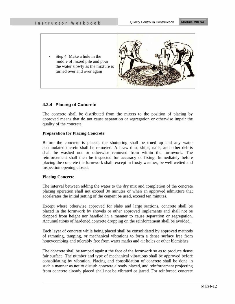
I n s t r u c t o r W o r k b o o k Quality Control in Construction Module M8/ S4
M8/S4-12
• Step 4: Make a hole in the middle of mixed pile and pour the water slowly as the mixture is turned over and over again
4.2.4 Placing of Concrete
The concrete shall be distributed from the mixers to the position of placing by approved means that do not cause separation or segregation or otherwise impair the quality of the concrete.
Preparation for Placing Concrete
Before the concrete is placed, the shuttering shall be trued up and any water accumulated therein shall be removed. All saw dust, ships, nails, and other debris shall be washed out or otherwise removed from within the formwork. The reinforcement shall then be inspected for accuracy of fixing. Immediately before placing the concrete the formwork shall, except in frosty weather, be well wetted and inspection opening closed.
Placing Concrete
The interval between adding the water to the dry mix and completion of the concrete placing operation shall not exceed 30 minutes or when an approved admixture that accelerates the initial setting of the cement be used, exceed ten minutes. Except where otherwise approved for slabs and large sections, concrete shall be placed in the formwork by shovels or other approved implements and shall not be dropped from height nor handled in a manner to cause separation or segregation. Accumulations of hardened concrete dropping on the reinforcement shall be avoided. Each layer of concrete while being placed shall be consolidated by approved methods of ramming, tamping, or mechanical vibrations to form a dense surface free from honeycombing and tolerably free from water marks and air holes or other blemishes. The concrete shall be tamped against the face of the formwork so as to produce dense fair surface. The number and type of mechanical vibrations shall be approved before consolidating by vibration. Placing and consolidation of concrete shall be done in such a manner as not to disturb concrete already placed, and reinforcement projecting from concrete already placed shall not be vibrated or jarred. For reinforced concrete
I n s t r u c t o r W o r k b o o k Quality Control in Construction Module M8/ S4
M8/S4-13
walls each other layer of concrete placed shall be properly consolidated by approved methods of mechanical vibrations produced by internal or external mechanical vibration. Any water accumulating on the surface of the newly placed concrete shall be removed by approved means and no further concrete shall be placed thereon until such water is removed. No fresh concrete shall be brought into contact with the concrete containing cement of different type. Unless otherwise approved or instructed, concrete shall be placed in a single operation to the full depth of slabs, beams, and members similar to these and shall be placed in horizontal layers not exceeding 0.90 m deep in walls, columns until completion of the of the work as specified. At the completion of a specified or approved part of the construction, joints of the form and in the position specified shall be made. If a temporary cessation of concrete placing is unavoidable a construction joint shall likewise be made.
4.2.5 Vibration
Appearance
The concrete that is to be compacted by vibration should appear anything from earth dry to slightly glistening. The mix should have the appearance of lacking in fines. Placing Segregation is likely to take place when the concrete is tipped into the formwork and this should be avoided. The concrete mix should not contain surplus water and sand which will develop segregation under influence of vibrator compaction. The distribution of new concrete should be uniform for the whole section and the surface kept horizontal for the whole section all the time thus ensuring the movement of concrete is downward only. Vibrators shall not be used as a spreading or distributing agent. The vibrators shall be of rotary out of balance immersion type or the electro-magnetic type and operate at a frequency of not less than 4,000 cycles per minute. The vibration shall be of such a power input as to produce an acceleration of 1 to 3 m/sec in the mass of the compacted concrete. The vibrators shall be provided for continuous operation. Disposition of Vibrators Internal vibrators shall be disposed within the mix, when placed, so as to maintain the whole of the concrete under treatment in adequate state of agitation such that de-aeration and effective compaction may be achieved at a rate commensurate with the supply of concrete from the mixers. Insertion of vibrators at about 450 mm center is considered sufficient. Period of Vibration
I n s t r u c t o r W o r k b o o k Quality Control in Construction Module M8/ S4
M8/S4-14
Vibration shall continue during the whole period occupied by placing the concrete, the vibration being adjusted so that the center of vibration approximates to center of the mass being compacted at the time of placing. The concrete should not be over vibrated and the period of insertion of internal vibration should be about 15 seconds at any point.
Compactness
The concrete shall be considered fully compacted when the mortar fills the spaces between the coarse aggregate so as to form a glistening and even surface except for slight irregularities where the coarse aggregate breaks this smooth surface. When this condition has been attained, the vibrators shall be withdrawn slowly.
The vibrator must not be placed against the steel or the formwork. The minimum distance shall be 8 mm. The compactor must be placed in such a position that formwork, reinforcement and recently laid concrete may be subjected to the minimum amount of vibration.
4.2.6 Protection and Curing of Concrete
Immediately after placing or finishing, concrete surface not covered by forms shall be protected from loss of surface moisture for at least seven days where Portland cement has been used. Protection from loss of surface water shall be done by any of the following methods where applicable to the type of work involved: a) By water covering. b) By covering of surface with water - impervious paper. c) By application of approved impervious membrane. Water curing shall be performed by keeping the concrete surface wet by ponding, by continuous spraying or by covering the surface with an approved water-saturated covering such as 2.5 mm. of sand or sawdust, or by one or more layers of burlap. The exposed concrete surfaces shall be saturated with water throughout the full stipulated curing period; they shall be kept sufficiently wetted with clean water to reduce cracks and to prevent joints from opening in the forms. The impervious membrane curing compound shall be an approved non bituminous, colorless, liquid, sealing compound in atomized form so as to preserve the natural color of the concrete. The curing compound shall be applied as soon as surface water has disappeared from concrete surfaces with approved pressure spraying equipment in accordance with the manufacturer's directions and in sufficient thickness to form an effective water seal. No compounds shall be used which will adversely affect the subsequent installation of finished flooring. Joints of sheet membrane used for curing shall be lapped at least 150 mm. and sealed with water proof tape as recommended by the manufacturer. Polyethylene sheet shall be considered the water-impervious paper for purposes of interpretation of this item.
I n s t r u c t o r W o r k b o o k Quality Control in Construction Module M8/ S4
M8/S4-15
No liquid curing compound may be used without specific written approval of the Engineer regarding type, manufacturer, location and extent of use and application procedures.
4.2.7 Cover of Concrete
Unless otherwise described, the clear cover of concrete to the reinforcement shall be as follows: a) Horizontal, vertical or inclined slabs: 15 mm or the size of the main bars
whichever is greater. b) Lintels: 20 mm or the size of the main bars whichever is greater. c) Beams: 25 mm or the size of the main bars whichever is greater, 15 mm
minimum for binders. d) Columns: For all columns having any diameter of reinforcement, the clear
cover shall be 40 mm or the size of the main bars whichever greater, 15 mm minimum is for rectangular binders or links or helical binding
4.2.8 Formwork
This consists of centering and shuttering including nailing, propping, strutting, wedging etc. and removal of forms including applying form oil to shuttering. Design Formwork shall be designed and constructed in such a manner that concrete can be properly placed and thoroughly compacted without any movement in the formwork. Formwork shall be firmly supported and adequately strutted, braced, or tied. It shall be capable of adjustment to the lines and dimensions of the finished concrete and it shall be sufficiently strong to resist without distortion, the pressure of concrete during its placing and compaction, and other loads to which it may be subjected. It shall not be liable to suffer distortion under the influence of the weather. When concrete is to be vibrated, special care shall be taken to ensure that the formwork will remain stable and the joints tight. The safety and adequacy of centering and shuttering is highly important. Supports Formwork shall be constructed in such a way that the formwork to the sides of members can be removed without disturbing the soffit formwork or its supports. Props and supports shall be designed to allow the formwork to be adjusted accurately to line and level and to be erected and removed in an approved sequence without injury to the concrete. Supports shall be erected on sufficiently strong base to avoid injury to any portion of the structure by its settlement. Props and bracing shall be
I n s t r u c t o r W o r k b o o k Quality Control in Construction Module M8/ S4
M8/S4-16
provided for the temporary support of composite construction where separately specified. Joints and Edges All joints in the formwork shall be close-fitted to prevent leakage of cement slurry from the concrete. At construction joints formwork shall be tightly secured against previously cast or hardened concrete to prevent the formation of stepping or ridges in the concrete. Formwork shall be constructed to provide straight and true angles, arises or edges. Cleaning and Treatment of Formwork Space to be occupied by concrete shall be free from all rubbish, chipping, shaving, sawdust, dirt and tying wire etc., before concrete in placed. The formwork to be in contact with the concrete shall be cleaned and treated with suitable non-staining form oil or other approved material. Care shall be taken that oil or composition is kept away from contact with the reinforcement or with concrete at any construction joints. Surface retarding agents shall not be used except with the permission of the Engineer. Formwork shall be thoroughly cleaned after each use. Damaged or distorted formwork shall not be used. Striking or Removal of Formwork All formwork shall be removed without shock or vibration that might damage the concrete. Before the soffit and props are removed the surface of the concrete shall be exposed where necessary in order to ensure that the concrete has hardened sufficiently. The formwork to vertical surfaces such as walls, columns and sides of beams may be removed after 24 hours in normal weather conditions although care must be taken to avoid damage to the concrete, especially to arise and features. In cold weather a longer period may be necessary before striking. Suitable curing methods should immediately follow the removal of the formwork. The following minimum times shall elapse before removal of formwork: a) Walls, column, vertical sides of beams - 24 hours b) Slabs and beams - 28 days
I n s t r u c t o r W o r k b o o k Quality Control in Construction Module M8/ S4
M8/S4-17
UNIT TEST 1) Describe three issues to be considered in design for quality control
• …. • … • …
2) What are the things to be considered for the selection of good quality of
cement • …… • …. • …. • … • …
3) Discuss factors of quality workmanship related to construction of walls
• … • … • … • …
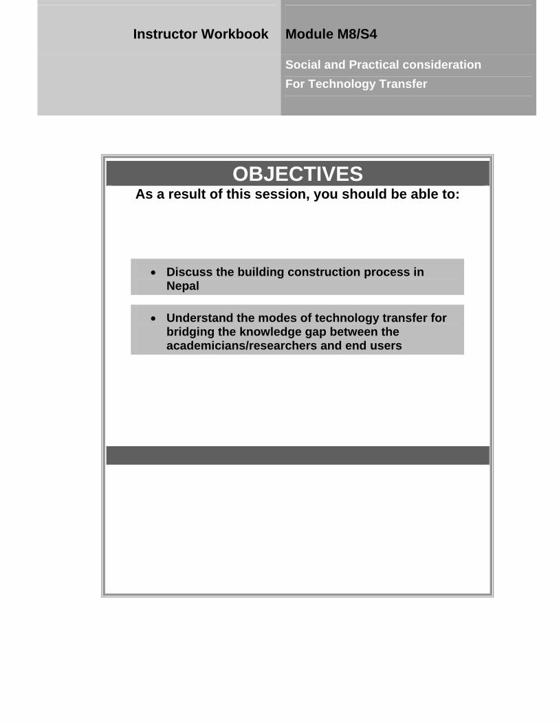
OBJECTIVES As a result of this session, you should be able to:
•• DDiissccuussss tthhee bbuuiillddiinngg ccoonnssttrruuccttiioonn pprroocceessss iinn NNeeppaall
• UUnnddeerrssttaanndd tthhee mmooddeess ooff tteecchhnnoollooggyy ttrraannssffeerr ffoorr bbrriiddggiinngg tthhee kknnoowwlleeddggee ggaapp bbeettwweeeenn tthhee aaccaaddeemmiicciiaannss//rreesseeaarrcchheerrss aanndd eenndd uusseerrss
Instructor Workbook Module M8/S4
Social and Practical consideration For Technology Transfer
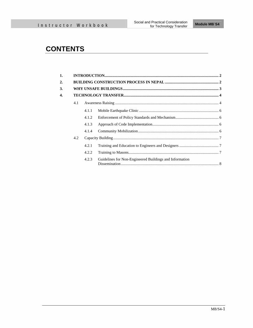
I n s t r u c t o r W o r k b o o k Social and Practical Consideration
for Technology Transfer Module M8/ S4
M8/S4-1
CONTENTS
1. INTRODUCTION ....................................................................................................................... 2
2. BUILDING CONSTRUCTION PROCESS IN NEPAL ........................................................ 2
3. WHY UNSAFE BUILDINGS .................................................................................................... 3
4. TECHNOLOGY TRANSFER ................................................................................................... 4
4.1 Awareness Raising ............................................................................................................ 4
4.1.1 Mobile Earthquake Clinic ................................................................................... 6
4.1.2 Enforcement of Policy Standards and Mechanism ............................................. 6
4.1.3 Approach of Code Implementation ..................................................................... 6
4.1.4 Community Mobilization .................................................................................... 6
4.2 Capacity Building .............................................................................................................. 7
4.2.1 Training and Education to Engineers and Designers ......................................... 7
4.2.2 Training to Masons .............................................................................................. 7
4.2.3 Guidelines for Non-Engineered Buildings and Information Dissemination ...................................................................................................... 8
I n s t r u c t o r W o r k b o o k Social and Practical Consideration
for Technology Transfer Module M8/ S4
M8/S4-2
1. INTRODUCTION Experiences from recent earthquakes have demonstrated that structures which are properly designed and constructed are able to withstand severe earthquake without collapse. However, these same earthquakes have shown that old buildings as well as buildings of recent construction can be seriously damaged or can collapse causing loss of life to the occupants. Despite the tremendous advancement in the technology in earthquake resistant building construction and demonstrated success of the technology to reduce impact of earthquakes, many earthquake prone countries are still struggling with the field implementation of appropriate building construction practice that resist earthquake. Design and construction of buildings require many small but vital factors to make these buildings earthquake-resistant. There are numerous earthquake codes and guidelines regarding safe building construction. Most of the earthquake prone countries already have established and enacted building code. Despite the fact, many buildings suffer damages in large earthquakes as evident from recent past earthquakes. In general, the quality of materials and workmanship for the houses existing and the houses under construction are below average and in many cases poor. The main reason is lack of knowledge in earthquake resistant buildings. This is because the actual construction is not proper due to lack of awareness and knowledge dissemination to the end users as the result of social and practical implications. People have very little concern and perception about earthquake safety as a result of which traditional constructions are coming down for ages. It is seen that long time is needed to develop new ideas from research to practice. This is especially so in the case of earthquake engineering due to its multidisciplinary nature. Considerable time is needed to successfully acquire new ideas from concept development, to basic and applied research, product development, codification and finally through to mainstream practice. The process from research to practice takes a time more considerably in developing countries. 2. BUILDING CONSTRUCTION PROCESS IN NEPAL Although there are significant increases in sub-urban area in numbers of buildings constructed by medium or large scale contractors, who can work rapidly and take all the responsibility for the buildings, owner-built housings are still common phenomena. Those buildings are generally non-engineered which are constructed informally in the traditional manner without any or little intervention by engineers. Meanwhile, the social issues which are surrounding those types of buildings are quite critical. Whilst there are high rate of non-engineered houses in the cities, as long as the building code and building code implementation is concerned, there is much lower level of awareness in the whole society including policy makers, building professionals, general public including potential house owners, and even educated masses. Hence, owner-built non-engineered buildings do not possess earthquake-resistant features in Nepal. Even engineered buildings do not have compliance with the seismic
I n s t r u c t o r W o r k b o o k Social and Practical Consideration
for Technology Transfer Module M8/ S4
M8/S4-3
demand unfortunately as engineering input is limited only to preparing architectural plans and not site-based works. Due to political and economic situation, there are phenomena of rapid erection of new unsafe buildings. When focusing on technology, majority of people still use low tech and cheap constructions of adobe, brick in mud, stone in mud etc. in semi-urban and remote areas. Some of the local materials remained in low quality including mud mortar and burnt bricks. Guidelines and other social functions ensure that any type of the building can be earthquake resistant as long as it follows adequate modalities with appropriate manpower and materials, though same level of safety cannot be achieved as in other modern methods of construction. But incorporation of earthquake resistant elements are not seen in prevalent buildings, whether it is RC frame buildings in urban and semi-urban areas or any other types of masonry buildings in semi-urban and rural areas, mostly built in informal manner and are unsafe for impending earthquake. 3. WHY UNSAFE BUILDINGS Informal constructions by unskilled local masons and craftsmen are the main reasons for unsafe buildings in earthquake. Combining building construction process as well as the mode of transmission of the construction, less than 10 percent of the buildings are engineered and over 90 percent are non-engineered, by craftsmen or local masons. In terms of pre-construction investment on the other hand, very less investment has been done to majority craftsmen whereas there are a lot of training and fostering process for engineers and sub-engineers. Practically, there is no investment for production of qualified construction workers in Nepal. The key stakeholders in housing construction in Nepal are the consultant-in-charge of design, construction supervisor, contractor or builders, masons, owner-builders, material suppliers and craftsmen. Craftsmen play crucial roles in non-engineered construction. They do not pay attention to the aspects on strength of the buildings and are negligent in completing details of the buildings. Indeed, there are huge gaps between professional engineers who employ the technical accuracy into the works and workmen who put them into practice at the construction site. The construction workers, who have a lot of experiences in their works, complain often to highly educated engineers that their practices in the field do not comply with “engineering” or “professional” approach. In actual case designers also do not take into account the practices when conducting their works of analysis and design. Not many engineers have the capability to perform structural analysis for non-engineered houses, and they already forgot about the correct way of laying bricks, mixing concrete, preparing correct reinforcing detailing for seismic resistance. Public perception is that the engineers are trouble makers. This unfortunately results in the poor quality of the houses built so far. In the developing countries there remains significant gap between what the construction workers do at the site and what the designers do. Promoting seismic safety is difficult. Earthquakes are not high on the political agenda because they occur infrequently and are overshadowed by more immediate, visible issues. Even where citizens are aware of seismic risks, taking action to improve
I n s t r u c t o r W o r k b o o k Social and Practical Consideration
for Technology Transfer Module M8/ S4
M8/S4-4
seismic safety is difficult because costs are immediate and benefits uncertain, public safety is not visible, benefits may not occur during the tenure of current elected officials. 4. TECHNOLOGY TRANSFER In any country undertaking the objective of achieving earthquake safe building construction, it must develop a holistic approach consisting of bottom-up as well as top-down approach. It has been found so far that there are huge gaps between engineering methods and actual construction conducted by manual workers whilst it is focused on the issues of implementation of engineering technologies into practices in order to mitigate the damage of earthquake disasters. Engineering frameworks in order to overcome the differences between methods and practice need to review on-site based feasibility of techniques from workmen to professional designers, and also the knowledge transfers from engineers to workmen. Practical solutions are required to help progress new ideas from the research to be mainstreamed into general practice. A large group of general public, who is aware of the impending disaster of living in vulnerable buildings, not only complies with the building code provisions but also creates demand for trained technicians, trained masons and trained builders. Therefore awareness raising and capacity buildings are inter-related issues and features as one of the key components in the approach of technology transfer and effective implementation of the appropriate technology. Two important components for technology transfer are:
1) Awareness Raising 2) Capacity Building
4.1 Awareness Raising
Despite the fact that Nepal lies in active seismic region, general awareness of people about the earthquake risk of Nepal is very little. In such condition awareness-raising of common people becomes a key for earthquake risk reduction. Community awareness is absolutely necessary. General awareness level of common people, professionals, school students, and teachers as well as of the authorities has to be increased significantly. However, there is a continued need of awareness-raising activities for large geographical coverage to cover whole country from rural, semi urban to urban areas. Awareness to various stakeholders, for example, schools, hospitals, industries, resident welfare associations, etc. for safer construction technology will be the most important issue since most losses in earthquakes occur due to the collapse of buildings. Information concerning the need to build earthquake resistant buildings, to use good quality materials and to adopt earthquake resistant features must be continuously and consistently disseminated to the community. This shall be the main
I n s t r u c t o r W o r k b o o k Social and Practical Consideration
for Technology Transfer Module M8/ S4
M8/S4-5
target to create awareness for the need to build earthquake resistant, non-engineered buildings incorporating earthquake resistant features in buildings as they are constructed. This activity will require a variety of commitments and adjustments on the part of the government. These include practical enforcement of building code, supporting other activities to improve the building construction practice and developing a public awareness program as the immediate goal. Through awareness related program, the involved social workers can contact with the community peoples directly and identify areas to be supported. The awareness program may be in various forms including model presentation of earthquake resistant construction technologies and shaking table demonstration. Shake table demonstration can be one of the practical methods for raising awareness in the people and it increases the people’s risk perception. This method can show the risk in quite simple manner in front of the community people. The objective of the shaking table is something which brings direct effect to the community; people can observe the importance of safety as a crucial part of their life. A program concerning the safety of buildings could be easily implemented if there is awareness in the society. It is easy to implement safety programs if the public is well aware of the seismic risks. Awareness programs are important part of the earthquake safety program which has resulted in significant public interest in the area of earthquake safe buildings. The awareness programs include Earthquake Safety Day Celebration, Exhibition of Earthquake Safety, publications, radio programs and interactions with public. Sensitization of the policy makers and top administrators towards priority actions require and funding to be provided for taking such actions. They need to be made aware of the following actions on priority:
• Creation of necessary legislative instruments for proper town planning as well as rural area habitation development.
• Land-use Zoning for developing Master Plans taking care of hazard proneness of the areas such as landslide and liquefaction potential affected by the earthquake activity.
• Development Control Regulations and appropriate Building Bylaws in the urban, semi-urban and rural bodies.
• Training of professionals including architects, engineers, construction supervisors, masons, bar benders and carpenters. It is to be understood that most non-engineered buildings are constructed in the informal manner without any involvement of architects or engineers, wherein the construction is carried out by master masons to meet the requirements of the owner. Trainings develop their social responsibility, professional ethic and need of changing in attitude and behavior with house owners and constructors.
In all these issues experts as well as the government have to play extremely important role. There are different modes of earthquake awareness activities:
I n s t r u c t o r W o r k b o o k Social and Practical Consideration
for Technology Transfer Module M8/ S4
M8/S4-6
4.1.1 Mobile Earthquake Clinic
NSET has launched mobile earthquake clinic as part of awareness activities. It is a clinic like program where a group of technical experts make visits to construction site. These technical experts get continuous feedbacks from the scientific research and could successfully create the platform of interaction of experiences and practice. The mobile team can provide necessary suggestions whatsoever is feasible right at construction site. At the same time the technical experts can provide awareness for the common peoples including owner builders regarding safer building construction. Once people are aware, they can create demands for more capable masons as well as for monitoring. Likewise, people could create not only safer houses but also a culture of disaster prevention.
4.1.2 Enforcement of Policy Standards and Mechanism
It is needed to create awareness at the top-policy enforcement level in terms of monitoring of the process. It should be adequately monitored, educated, penalized for those who go beyond the regulations, and encourage the process with so many legal and semi-legal instruments: Policy, Standards, Guidelines and Mechanisms, which lead the society to the enforcement. In return from the society, it is needed to enhance the compliance of the community towards the implementation of the building code. When working on bottom-up approach, there are several tools available. But at the same time, strong policy support and environment is indispensable for such activities. Hence both top down and bottom up approach should be applied simultaneously.
4.1.3 Approach of Code Implementation
Earthquakes kill thousands of people and majority of the death is caused by collapse of buildings. Effective implementation of building codes can prevent collapse of these buildings and thousands of lives can be saved from earthquakes. Although most of the earthquake prone countries have now building codes, implementation of the building code is poor and many unsafe buildings are still being raised. This has realized the importance of effective implementation of building code in earthquake risk reduction. Disseminating building code is an effective tool to safeguard houses from earthquake disaster. Compliance is difficult to achieve without awareness. House owner who is aware of the practical measures to reduce earthquake risk in building prefers to follow the standard easily.
4.1.4 Community Mobilization
Even the process needs to be expanded and brought in more people to make the chain of people’s awareness. This requires community mobilization in mass scale. It is quite a huge task and should be conducted under the concept of social mobilization. The first approach is to give people some technical know-how, people begins incorporate
I n s t r u c t o r W o r k b o o k Social and Practical Consideration
for Technology Transfer Module M8/ S4
M8/S4-7
learnt skills in social aspects. The process, therefore, needs participation of sociologist, psychologist and workers who help dissemination of the culture of prevention. Broader scheme is implementing building code in various corners of the country to lead ultimately to safer house construction and the culture of seismic safety. In this process, the group could successfully involve not only social-motivators but also building inspectors. The project can be successful having cooperation between experts of social work and technical experts. With such process and different adaptation of the methodology, earthquake resistant technology can be transmitted and practically implemented.
4.2 Capacity Building
Capacity building of all stakeholders is the key factor for earthquake risk reduction. Capacity building of technical persons including designers and masons is important. Hundreds of designers and engineers are involved in design and construction of buildings and thousands of masons are involved. In addition to that house owners, contractors, builders and municipal authorities also need awareness raising and capacity building programs.
4.2.1 Training and Education to Engineers and Designers
Designers and supervisors play a vital role for the effective implementation of the Building Code in construction. They need to take responsibility for motivating and convincing house owners and constructors to apply earthquake resistant techniques by utilizing their technical knowledge and skill. These trainings should focus more on practical basis. Engineers should learn actual condition of construction sites, and elaborate proposal based on actual conditions. Also, it would be quite indispensable to verify the feasibility of design on construction sites through monitoring/model projects etc and give feedback inputs from construction sites to engineering. No doubt earthquake engineering must be introduced in the regular course of civil engineering and the subject on building construction must be refreshed. However, a lot more remains to be done to raise the competence regarding non-engineered buildings. It is essential for the successful implementation of improved construction practices for earthquake resistance that engineers and architects be familiar with these requirements. Therefore, the competence of engineers and architects entrusted with design and supervision of non-engineered buildings should be upgraded.
4.2.2 Training to Masons
Construction habits are usually dictated by tradition, popular trends, availability and cost of labor and materials. Generally masons learn the trade from hands on experience in the field. These are the practice of masons as a trade adopted by many generations within a family. Such traditionally owned practices lack in competency level. Such masons may not be able to spare the time and resources to attend a full time mason three year training course but would benefit immensely from additional knowledge of good building construction practices in areas of earthquake risk from
I n s t r u c t o r W o r k b o o k Social and Practical Consideration
for Technology Transfer Module M8/ S4
M8/S4-8
short term mason training courses of 4-5 days. The objective of the mason training is to provide masons with earthquake resistant construction technology and know how and to raise the competence of the construction workers. A skill certification program will allow them to test their skills and improve themselves in the areas they are deficient in. Main focus should remain on bottom-up/on-site based approach, where it is considered the feasibility of practical incorporation of engineering techniques at the construction site adding to the design instruction granted by professional engineers. These construction workers who have less knowledge should learn more from the engineers and designers. There is no doubt that the knowledge transfers from engineers and designers to construction workers are crucial. Knowledge transfer may not be effective without practical and efficient means of implementation at site. In the case of making bend for RC bars, simple and technically appropriate tools should be developed. Furthermore, efforts to simplify the modes of trainings by showing actual construction materials, actual construction methodology, should be made and updated regularly. It is though obvious that increased awareness and enhanced capacity of masons help implementing building code effectively and practically. Making decision at the top level alone is not sufficient for the challenge of implementation. It should be needed to have sufficient number of capable professionals in the field. Meanwhile, bottom-up approach is powerful for effective building code implementation.
4.2.3 Guidelines for Non-Engineered Buildings and Information Dissemination
Guidelines are the source of guidance to promote consistency in the quality of building construction. Several guidelines and manuals are available with the main objective of improving the seismic safety of housing constructions. The current problem of earthquake risk is due to little or no awareness of the contractors, engineers, architects as well as construction workers. The goal to advocate for a reduction in vulnerability and capacity building for disaster preparedness is reached in one way from the implementation of available manuals and guidelines. Effective communication of correct techniques for earthquake resistant houses is essential. Performance based guidelines rather than specification based guidelines should be developed. It should be more an expression of desired results than a set of instructions on how to attain that. Although the technology may be known by engineers/architects and those involved in housing development, guidelines based on use of simple materials and easily understandable to the villagers must be developed and disseminated. Minimum building standards based on building performance and emphasizing the safety of the occupants developed by the government for non-engineered buildings should be more useful.
.
I n s t r u c t o r W o r k b o o k Social and Practical Consideration
for Technology Transfer Module M8/ S4
M8/S4-9
UNIT TEST 1) Describe the building construction process in Nepal
• … • … • …
2) State the problems in building construction process in Nepal • … • … • … • …
3) Discuss two major modes of technology transfer
• … • …

![Former Employees [187 co-workers]...Former Employees [187 co-workers] Francis Ackerman Sr. St. Vivian Agnes, BVM Jean Allen Rita Ambrosy Laurie Andresen Sr. Jolenta Arth, BVM Lillian](https://static.fdocuments.nl/doc/165x107/60bfcfc2b567454982361f5c/former-employees-187-co-workers-former-employees-187-co-workers-francis.jpg)