Biomass gasification and gas cleaning
25
Resultaten en bevindingen van project Biomass gasification and gas cleaning Dit rapport is onderdeel van de projectencatalogus energie-innovatie. Tussen 2005 en 2011 kregen ruim 1000 innovatieve onderzoeks- en praktijkprojecten subsidie. Ze delen hun resultaten en bevindingen, ter inspiratie voor nieuwe onderzoeks- en productideeën. De subsidies werden verleend door de energie-innovatieprogramma's Energie Onderzoek Subsidie (EOS) en Innovatie Agenda Energie (IAE). Datum 2010 Status Definitief Energieonderzoek Centrum Nederland (ECN), e.a. in opdracht van Agentschap NL Resultaten en bevindingen van project Biomass gasification and gas cleaning Dit rapport is onderdeel van de projectencatalogus energie-innovatie. Tussen 2005 en 2011 kregen ruim 1000 innovatieve onderzoeks- en praktijkprojecten subsidie. Ze delen hun resultaten en bevindingen, ter inspiratie voor nieuwe onderzoeks- en productideeën. De subsidies werden verleend door de energie-innovatieprogramma's Energie Onderzoek Subsidie (EOS) en Innovatie Agenda Energie (IAE). Datum 2010 Status Definitief Energieonderzoek Centrum Nederland (ECN), e.a. in opdracht van Agentschap NL
Transcript of Biomass gasification and gas cleaning
Resultaten en bevindingen van project
Biomass gasification and gas cleaning
Dit rapport is onderdeel van de projectencatalogus energie-innovatie. Tussen 2005 en 2011 kregen ruim 1000 innovatieve onderzoeks- en praktijkprojecten subsidie. Ze delen hun resultaten en bevindingen, ter inspiratie voor nieuwe onderzoeks- en productideeën. De subsidies werden verleend door de energie-innovatieprogramma's Energie Onderzoek Subsidie (EOS) en Innovatie Agenda Energie (IAE).
Datum 2010 Status Definitief Energieonderzoek Centrum Nederland (ECN), e.a. in opdracht van Agentschap NL

Colofon
Projectnaam Biomass gasification and gas cleaning Programma Energie Onderzoek Subsidie Regeling Lange Termijn Projectnummer EOSLT08007 Contactpersoon Energieonderzoek Centrum Nederland (ECN) Hoewel dit rapport met de grootst mogelijke zorg is samengesteld kan Agentschap NL geen enkele aansprakelijkheid aanvaarden voor eventuele fouten.
Biomass gasification and gas cleaning, Report PERIOD 3 (April 2009 – April 2010)
1
Biomass gasification and gas cleaning Report Period 3
Edited by L.P.L.M. Rabou (ECN)
Final report of period 3 (April 2009-April 2010) by consortium of ECN, Twente University (UT), University of Eindhoven (TU/e), University of Delft (TUD), Biomass Technology Group (BTG)
Biomass gasification and gas cleaning, Report PERIOD 3 (April 2009 – April 2010)
2
CONTENT CONTENT...................................................................................................................................... 2 PROJECT DATA............................................................................................................................ 3 1. SUMMARY........................................................................................................................ 4 2. BACKGROUND ................................................................................................................ 7
2.1 Problem definition....................................................................................................................... 8 2.2 Objectives.................................................................................................................................... 8 2.3 Relation with ECN Long-term programme................................................................................. 9
3. ACTIVITIES..................................................................................................................... 10 3.1 Technical approach and results ................................................................................................. 10
3.1.1. Expected results .................................................................................................................... 10 3.1.2. Time schedule....................................................................................................................... 11 3.1.3. Relations between tasks........................................................................................................ 12
3.2 Costs.......................................................................................................................................... 13 4. RESULTS ......................................................................................................................... 14
4.1. Task 1: in-bed measures .............................................................................................................. 14 4.2. Task 2: gas cooling...................................................................................................................... 15 4.3. Task 3: tar reduction with radicals .............................................................................................. 15 4.4. Task 4: catalytic oil gasification.................................................................................................. 17 4.5. Task 5: self-gasification............................................................................................................... 18 4.6. Task 6: catalytic (tar) reforming.................................................................................................. 18 4.7. Task 7: syngas production through pyrolysis .............................................................................. 20
5. PROGRESS ...................................................................................................................... 22 5.1. Technical and organisational problems ........................................................................................... 22 5.2. Deviations from original plan.......................................................................................................... 22 5.3. Budget changes................................................................................................................................ 22
6. CONTRIBUTION TO EOS LONG TERM OBJECTIVES............................................. 22 7. OUTCOME INDICATORS.............................................................................................. 22 8. REFERENCES ................................................................................................................. 22
Biomass gasification and gas cleaning, Report PERIOD 3 (April 2009 – April 2010)
3
PROJECT DATA • Project number: EOSLT08007 • Project title: Biomass gasification and gas cleaning • Penvoerder en mede-aanvragers: ECN, Twente University (UT), University of Eindhoven (TUE),
University of Delft (TUD), Biomass Technology Group (BTG) • Project period: 1 April 2009 – 1 April 2010 Het project is uitgevoerd met subsidie van het Ministerie van Economische Zaken, regeling EOS: Lange Termijn uitgevoerd door SenterNovem.
Biomass gasification and gas cleaning, Report PERIOD 3 (April 2009 – April 2010)
4
1. SUMMARY It is assumed that gasification will play a key role in the conversion of biomass to energy. In any of the possible energy sections: heat, electricity, transportation fuels, and products and chemicals, gasification is an option with significant advantages concerning efficiency, flexibility, and emissions. Technological options have been identified to produce the energy carriers mentioned in the EOS-LT programme: SNG, electricity and heat, transportation fuels, and H2. It has been reasoned that long-term systems come down to two routes: - Indirect gasification (and self gasification as an extreme version) for the production of SNG (and
power) - Entrained flow gasification for the production of syngas (for transportation fuel, products, chemicals,
H2, and even power) The long term goals are summarized as follows: - SNG in large-scale plants with 70-75% overall efficiency with capital costs and operation and
maintenance contributing max. 4-5 €/GJSNG to the production costs of SNG. - Syngas (for transportation fuels or H2 or bulk chemicals) in large-scale plants with 80% efficiency
with capital costs and operation and maintenance contributing 3-4 €/GJsyngas to the production costs of syngas.
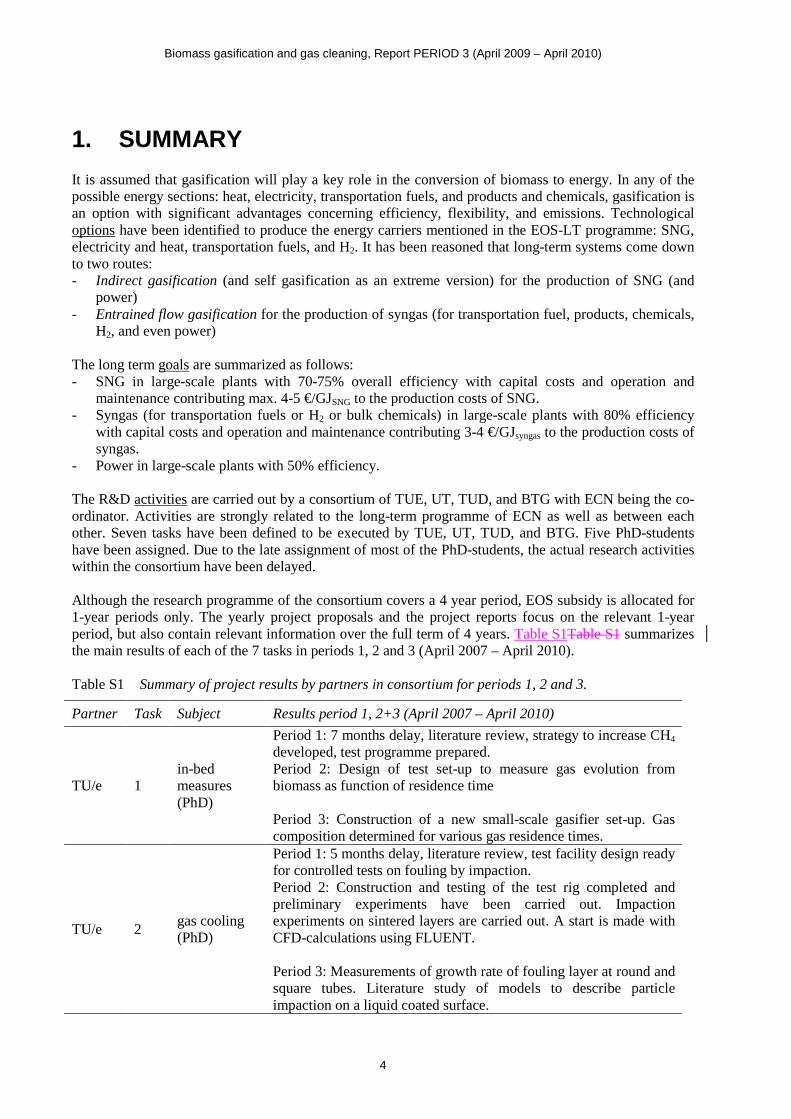
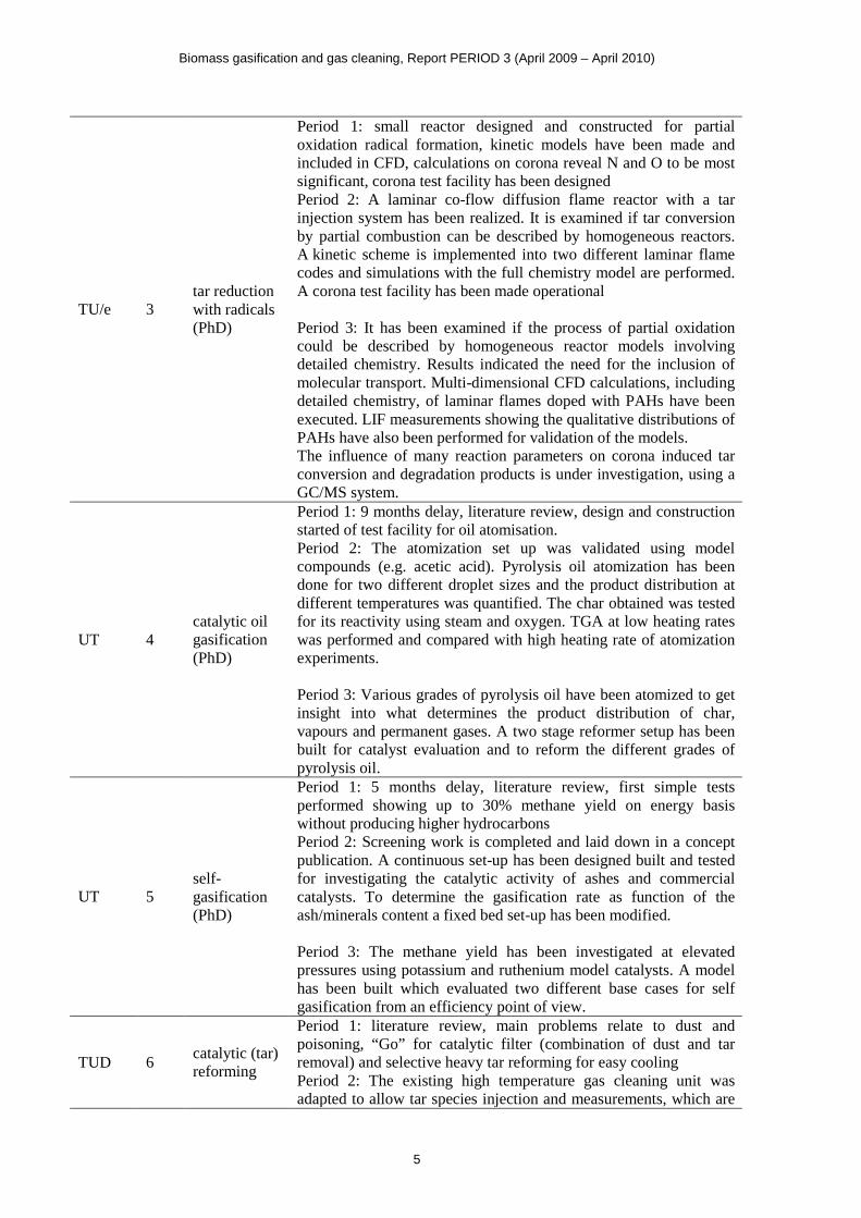
- Power in large-scale plants with 50% efficiency. The R&D activities are carried out by a consortium of TUE, UT, TUD, and BTG with ECN being the co-ordinator. Activities are strongly related to the long-term programme of ECN as well as between each other. Seven tasks have been defined to be executed by TUE, UT, TUD, and BTG. Five PhD-students have been assigned. Due to the late assignment of most of the PhD-students, the actual research activities within the consortium have been delayed. Although the research programme of the consortium covers a 4 year period, EOS subsidy is allocated for 1-year periods only. The yearly project proposals and the project reports focus on the relevant 1-year period, but also contain relevant information over the full term of 4 years. Table S1Table S1 summarizes the main results of each of the 7 tasks in periods 1, 2 and 3 (April 2007 – April 2010). Table S1 Summary of project results by partners in consortium for periods 1, 2 and 3. Partner Task Subject Results period 1, 2+3 (April 2007 – April 2010)
TU/e 1 in-bed measures (PhD)
Period 1: 7 months delay, literature review, strategy to increase CH4 developed, test programme prepared. Period 2: Design of test set-up to measure gas evolution from biomass as function of residence time Period 3: Construction of a new small-scale gasifier set-up. Gas composition determined for various gas residence times.
TU/e 2 gas cooling (PhD)
Period 1: 5 months delay, literature review, test facility design ready for controlled tests on fouling by impaction. Period 2: Construction and testing of the test rig completed and preliminary experiments have been carried out. Impaction experiments on sintered layers are carried out. A start is made with CFD-calculations using FLUENT. Period 3: Measurements of growth rate of fouling layer at round and square tubes. Literature study of models to describe particle impaction on a liquid coated surface.
Biomass gasification and gas cleaning, Report PERIOD 3 (April 2009 – April 2010)
5
TU/e 3 tar reduction with radicals (PhD)
Period 1: small reactor designed and constructed for partial oxidation radical formation, kinetic models have been made and included in CFD, calculations on corona reveal N and O to be most significant, corona test facility has been designed Period 2: A laminar co-flow diffusion flame reactor with a tar injection system has been realized. It is examined if tar conversion by partial combustion can be described by homogeneous reactors. A kinetic scheme is implemented into two different laminar flame codes and simulations with the full chemistry model are performed. A corona test facility has been made operational Period 3: It has been examined if the process of partial oxidation could be described by homogeneous reactor models involving detailed chemistry. Results indicated the need for the inclusion of molecular transport. Multi-dimensional CFD calculations, including detailed chemistry, of laminar flames doped with PAHs have been executed. LIF measurements showing the qualitative distributions of PAHs have also been performed for validation of the models. The influence of many reaction parameters on corona induced tar conversion and degradation products is under investigation, using a GC/MS system.
UT 4 catalytic oil gasification (PhD)
Period 1: 9 months delay, literature review, design and construction started of test facility for oil atomisation. Period 2: The atomization set up was validated using model compounds (e.g. acetic acid). Pyrolysis oil atomization has been done for two different droplet sizes and the product distribution at different temperatures was quantified. The char obtained was tested for its reactivity using steam and oxygen. TGA at low heating rates was performed and compared with high heating rate of atomization experiments. Period 3: Various grades of pyrolysis oil have been atomized to get insight into what determines the product distribution of char, vapours and permanent gases. A two stage reformer setup has been built for catalyst evaluation and to reform the different grades of pyrolysis oil.
UT 5 self-gasification (PhD)
Period 1: 5 months delay, literature review, first simple tests performed showing up to 30% methane yield on energy basis without producing higher hydrocarbons Period 2: Screening work is completed and laid down in a concept publication. A continuous set-up has been designed built and tested for investigating the catalytic activity of ashes and commercial catalysts. To determine the gasification rate as function of the ash/minerals content a fixed bed set-up has been modified. Period 3: The methane yield has been investigated at elevated pressures using potassium and ruthenium model catalysts. A model has been built which evaluated two different base cases for self gasification from an efficiency point of view.
TUD 6 catalytic (tar) reforming
Period 1: literature review, main problems relate to dust and poisoning, “Go” for catalytic filter (combination of dust and tar removal) and selective heavy tar reforming for easy cooling Period 2: The existing high temperature gas cleaning unit was adapted to allow tar species injection and measurements, which are
Biomass gasification and gas cleaning, Report PERIOD 3 (April 2009 – April 2010)
6
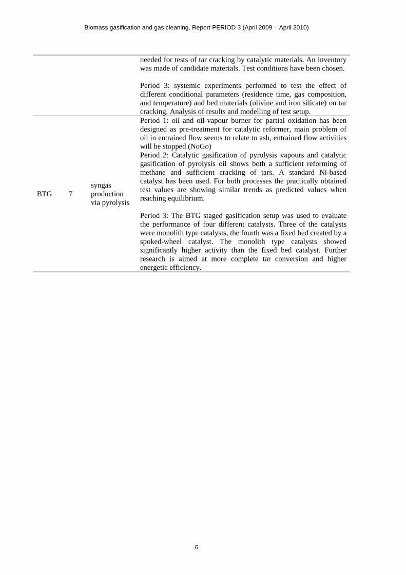
needed for tests of tar cracking by catalytic materials. An inventory was made of candidate materials. Test conditions have been chosen. Period 3: systemic experiments performed to test the effect of different conditional parameters (residence time, gas composition, and temperature) and bed materials (olivine and iron silicate) on tar cracking. Analysis of results and modelling of test setup.
BTG 7 syngas production via pyrolysis
Period 1: oil and oil-vapour burner for partial oxidation has been designed as pre-treatment for catalytic reformer, main problem of oil in entrained flow seems to relate to ash, entrained flow activities will be stopped (NoGo) Period 2: Catalytic gasification of pyrolysis vapours and catalytic gasification of pyrolysis oil shows both a sufficient reforming of methane and sufficient cracking of tars. A standard Ni-based catalyst has been used. For both processes the practically obtained test values are showing similar trends as predicted values when reaching equilibrium. Period 3: The BTG staged gasification setup was used to evaluate the performance of four different catalysts. Three of the catalysts were monolith type catalysts, the fourth was a fixed bed created by a spoked-wheel catalyst. The monolith type catalysts showed significantly higher activity than the fixed bed catalyst. Further research is aimed at more complete tar conversion and higher energetic efficiency.
Biomass gasification and gas cleaning, Report PERIOD 3 (April 2009 – April 2010)
7
2. BACKGROUND This Section contains the main points from the long-term programme of ECN [1], which serves as reference for underlying proposal. Energy segments The EOS-LT programme as defined in 2004 [2, 3] distinguishes three energy market segments relevant within the research area “biomass gasification, gas cleaning, conditioning and syngas production” (area 2.2.7): - Gaseous fuels (SNG, H2), - Electricity and heat, - Transportation fuels (and chemicals). Several technological options have been identified to convert biomass into one of above-mentioned energy products. A short description and the main characteristics are summarized in [1]. Gasification This section contains the plan to perform research and development within the EOS area “biomass gasification, gas cleaning, conditioning and syngas production”. This plan therefore focuses on gasification as the principal biomass conversion process. Gasification concepts often are considered promising because of reasons like improved environmental performance, fuel flexibility, output flexibility, emissions, and efficiency. Scale It is envisaged that biomass gasification in the Netherlands ultimately should take place at large scale. This not only results in relatively high efficiencies, low specific costs, better emission and less non-technical problems (permits, locations), it also reduces logistic costs as in the Netherlands a significant amount of biomass must be imported to reach the 2020 and 2040 renewable goals. Small-scale gasification however, will play a crucial role for (1) the cheap conversion of local biomass, and (2) the smooth transition to large-scale systems. Criteria Each biomass-to-energy option is characterised by efficiency, costs, technological status, scale, fuel flexibility, ash/mineral recycle, etc. Technological choices are made on the basis of these characteristics, but also by external facts such as the desire to quickly satisfy e.g. a biofuels target, the ease of acquiring permits, or the familiarity of the initiator with a certain technology. Efficiency The energy efficiency is considered a very important quantitative measure of any biomass-based system since biomass is and will be available in limited quantities. This means that biomass will have a high positive value1 and thus economics of biomass-to-energy systems will depend to a great extent on efficiency2. This especially is the case for large-scale systems with relatively low capital costs. The efficiency has been calculated assuming dried wood as fuel [1]. This excludes the option of heat integration between gasification plant and dryer. Heat integration generally increases the overall efficiency3.
1 Future biomass prices are hard to predict, but biomass in the Netherlands is expected to be relatively expensive. Given the
limited national resources, biomass should be imported to a great extent in order to reach long-term (and even short-term) energy goals. Imported biomass inevitably is expensive. Imported biomass is expected to be at least 7 €/GJ or 25 €/MWh [4].
2 Assuming a biomass price of 7 €/GJ or 25 €/MWh for imported wood, biomass already contributes as much as 50 €/MWhe to the power production costs (assuming a very high-efficient power plant with 50% efficiency). Assuming a realistic investment of 1000 €/kWe an additional 25 €/MWhe for capital costs including operation and maintenance can be calculated. It is clear that the biomass price dominates the power costs: efficiency is a crucial parameter.
3 The lower heating value (LHV) of a fuel increases on drying. If the dryer’s energy demand is satisfied by waste heat (e.g. low-temperature heat, not suitable for steam generation) from within the gasification plant, the dryer becomes an efficiency booster.
Biomass gasification and gas cleaning, Report PERIOD 3 (April 2009 – April 2010)
8
Capital costs Capital costs evidently form another important criterion to discriminate between different options. However, it must be realized that for large-scale systems (i.e with relatively low capital costs) operating on imported (i.e. relatively expensive) biomass, the fuel costs will probably be dominant. This has been quantified in footnote 2. The determination of investment costs of future systems is not easy and will be part of the activities of the long-term programme. Two routes selected In [1] the technological options are described to produce the energy carriers: SNG, electricity and heat, transportation fuels, and H2. The “best” technologies have been identified. Short-term options have been selected mainly on the basis of availability of technology, whereas long-term options are selected by their energy efficiency, being the main cost driver of large-scale systems operating on imported biomass. It has been reasoned that long-term systems come down to two routes: indirect gasification for SNG and entrained flow gasification for syngas: - Indirect gasification (and self gasification as an extreme version) enables biomass-to-SNG systems
with efficiencies of 75%. This is significantly higher than any of the alternative systems. Since the preferred long-term biomass-to-SNG system contains gas cleaning concepts that largely resemble those of short-term CHP systems, this offers a logical technology development path. At the same time, indirect gasification offers the possibility to have long-term CHP plants with improved performance. R&D mainly involves the increase of pressure and scale as well as the actual SNG synthesis.
- Entrained flow gasification seems the best choice for the production of syngas (for transportation fuel, products, chemicals, H2, and even power). The main reason is the availability of the large-scale entrained flow technology for coal/biomass and the Dutch know-how in this field (NUON, Shell). R&D mainly involves feeding and slag behaviour while increasing the biomass/coal-ratio.
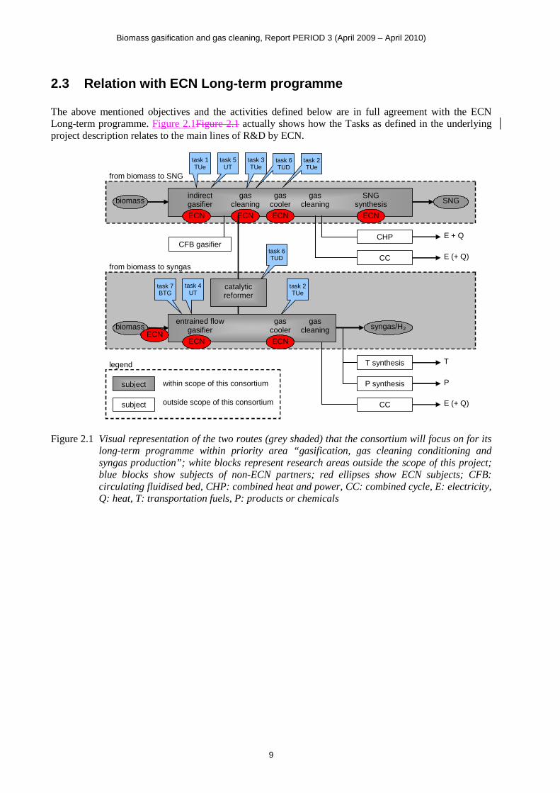
The two main routes as depicted above are correlated in several ways. Firstly, indirect gasification can be used to produce syngas by applying a catalytic reformer. From an efficiency point of view, this is very attractive [1]. Secondly, syngas from entrained flow gasification and gas produced by indirect gasification can both be used to generate power (and heat). Figure 2.1Figure 2.1 shows a schematic representation of the choices made in the long-term programme and the tasks of the different consortium partners.
2.1 Problem definition Satisfying (Dutch) long-term energy targets requires low cost and reliable biomass systems. Although some successful examples exist of biomass gasification plants worldwide, these are not complete (e.g. co-firing plants), not the optimum choice for the required product, not scalable, only working with low biomass/coal ratio, low efficient, or do not satisfy emission limits. Two long-term routes have been selected mainly on the basis of efficiency and technology status. For these routes to become commercially available, considerable R&D is needed.
2.2 Objectives The aim of the biomass syngas and SNG programme is the development of gasification systems to convert biomass efficiently into SNG and syngas, and in next steps into electricity and heat, and transportation fuels and H2. The targets will be to have at least 75% cold gas efficiency for the gasifier and 85% efficiency in CHP-plants. Furthermore, chosen concepts and developed technologies must enable the realization of the mineral cycle. It finally must be possible to compete with fossil fuels.
Biomass gasification and gas cleaning, Report PERIOD 3 (April 2009 – April 2010)
9
2.3 Relation with ECN Long-term programme The above mentioned objectives and the activities defined below are in full agreement with the ECN Long-term programme. Figure 2.1Figure 2.1 actually shows how the Tasks as defined in the underlying project description relates to the main lines of R&D by ECN.
task 2 TUe
task 6 TUD
task 6 TUD
task 2 TUe
task 7 BTG
CFB gasifier
ECN ECN ECN
ECN ECN
ECN
ECN
biomass
task 4 UT
indirect gasifier
gas cooler
gas cleaning
SNG synthesis
catalytic reformer
gas cleaning
gas cooler
gas cleaning
CHP
CC
CC
T synthesis
P synthesis
biomass SNG
E + Q
E (+ Q)
E (+ Q)
T
P
syngas/H2
from biomass to SNG
from biomass to syngas
subject
legend
subject
within scope of this consortium
outside scope of this consortium
task 5 UT
task 3 TUe
task 1 TUe
entrained flow gasifier
Figure 2.1 Visual representation of the two routes (grey shaded) that the consortium will focus on for its long-term programme within priority area “gasification, gas cleaning conditioning and syngas production”; white blocks represent research areas outside the scope of this project; blue blocks show subjects of non-ECN partners; red ellipses show ECN subjects; CFB: circulating fluidised bed, CHP: combined heat and power, CC: combined cycle, E: electricity, Q: heat, T: transportation fuels, P: products or chemicals
Biomass gasification and gas cleaning, Report PERIOD 3 (April 2009 – April 2010)
10
3. ACTIVITIES
3.1 Technical approach and results Figure 2.1Figure 2.1 shows the two routes selected as main systems for reasons as described above. The work has been divided into corresponding activities that are performed by the consortium partners. The activities are described below and summarized in Table 3.1Table 3.1. It needs to be stressed that the consortium will not duplicate the work of others, but will join where possible. Partners are well informed on international progress through their participation in different European projects, NoE (Network of Excellence), IEA (task 33: biomass gasification), ThermalNet, and GasNet. Table 3.1 Summary of tasks of partners within the consortium programme. Partner Task Subject Remarks
ECN co-ordination according to long-term R&D programme, see also text above [1]
TU/e 1 in-bed measures 1 PhD TU/e 2 gas cooling 1 PhD TU/e 3 tar reduction with radicals 1 PhD plus support by faculty E UT 4 catalytic oil gasification 1 PhD plus support by BTG, see also task 7 UT 5 self-gasification 1 PhD TUD 6 catalytic (tar) reforming Go after year 1: will be continued BTG 7 syngas production via pyrolysis NoGo after year 1 on entrained flow option Consortium activities are focused on long-term objectives. The link to short- and medium-term is of extreme importance and is realized though several projects and co-operations with industry outside the underlying programme, such as EOS-KTO and direct industrial assignments. This not only adds the industrial perspective to the underlying consortium project, it also offers the platform to feed the industry with viable concepts and technologies to finally have commercial implementation.
3.1.1. Expected results The programme is aimed at the realization of long-term plants for the reliable and cheap production of: - SNG in large-scale plants with 70-75% overall efficiency (approx. 10%abs. improvement compared
to systems that can be realized on short-term); capital costs are expected to ultimately contribute 4-5 €/GJSNG to the production costs of SNG4
- Syngas (for transportation fuels or H2 or bulk chemicals) in large-scale plants with 80% efficiency (approx. 10%abs improvement compared to systems that can be realized on short-term, or approx. 5%abs. compared to a state-of-the-art coal/biomass plant); capital costs are expected to ultimately contribute 3-4 €/GJsyngas to the production costs of syngas5,
- Power in large-scale plants with 50% efficiency (approx. 20%abs improvement compared to biomass systems that can be realized on short-term, or approx. 3%abs. compared to a state-of-the-art coal/biomass plant).
Two routes have been selected (see Figure 2.1Figure 2.1) that enable the realization of above-mentioned objectives: indirect gasification (or self gasification) for SNG and entrained flow gasification for syngas (for transportation fuels or H2). These systems also enable the implementation of high-efficient power production and CHP. 4 This refers to investment and operation and maintenance of the main equipment of a commercial nth plant, not including
(overseas) pre-treatment like pelletizing. 5 This refers to investment and operation and maintenance of the main equipment of a commercial nth plant, not including
(overseas) pre-treatment like torrefaction, this can add another 1-2 €/GJ to the syngas price, but is expected to reduce the total costs by a larger amount due to reduced transport and transshipment costs.
Biomass gasification and gas cleaning, Report PERIOD 3 (April 2009 – April 2010)
11
Not included The project focuses on two main routes to SNG and clean syngas respectively. Not included in the programme is R&D concerning syngas applications such as catalytic processes to produce biofuels or products/chemicals. Also not included is research and development on power blocks like combined cycle and gas engine. These subjects are covered by different EOS-LT areas.
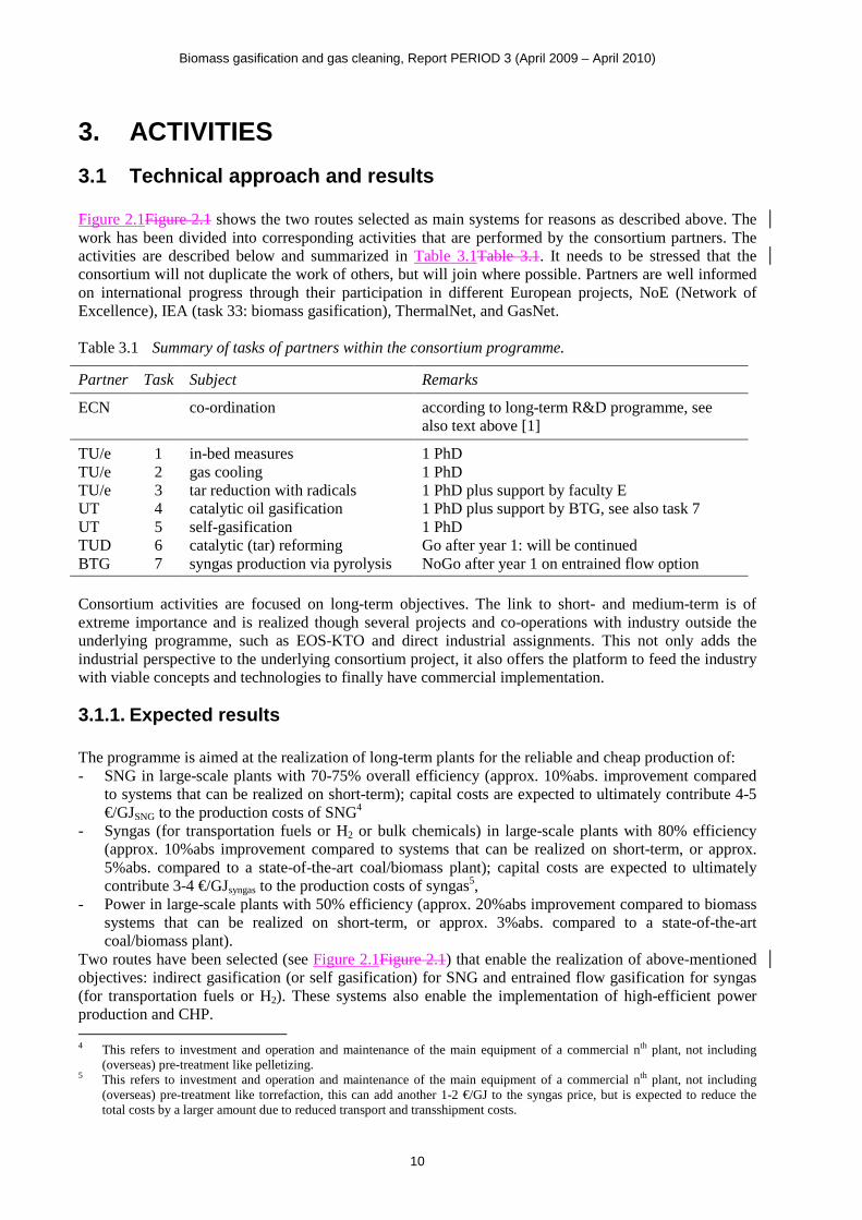
3.1.2. Time schedule The consortium’s project consists of 7 tasks, see Figure 2.1Figure 2.1 and Table 3.1Table 3.1. The first 5 tasks are performed through PhD-students (AIO’s). Their names and 4-year period are indicated in Figure 3.1Figure 3.1 below. Since most of the PhD-students did not start their 4-years period at April 1st 2007, their individual time schedules will require extension of the consortium’s project after April 2011. In case of the one PhD-student who did start at April 1st 2007, an extension will be required because of maternity leave in 2009.
task PhD-student (AIO) 4 5 6 7 8 9 10 11 12 1 2 3 4 5 6 7 8 9 10 11 12 1 2 3 4 5 6 7 8 9 10 11 12 1 2 3 4 5 6 7 8 9 10 11 12 1 2 3 4 5 6 7 8 9 10 11 12
1 Carlos Vilela 1 1 1 1 1
2 Kiran Kumar 2 2 2 2 2
3 Liselotte Verhoeven 3 3 3 3 3
4 Prasad 4 4 4 4 4
5 Pavlina Nanou 5 5 5 5 5
6 none 6 6 6 6 6
7 none 7 7 7 7 7
extensionYEAR 1 YEAR 2 YEAR 3 YEAR 4
20112007 2008 2009 2010
Figure 3.1 Seven tasks and their time schedule deviations due to the late assignment of 4 PhD-students
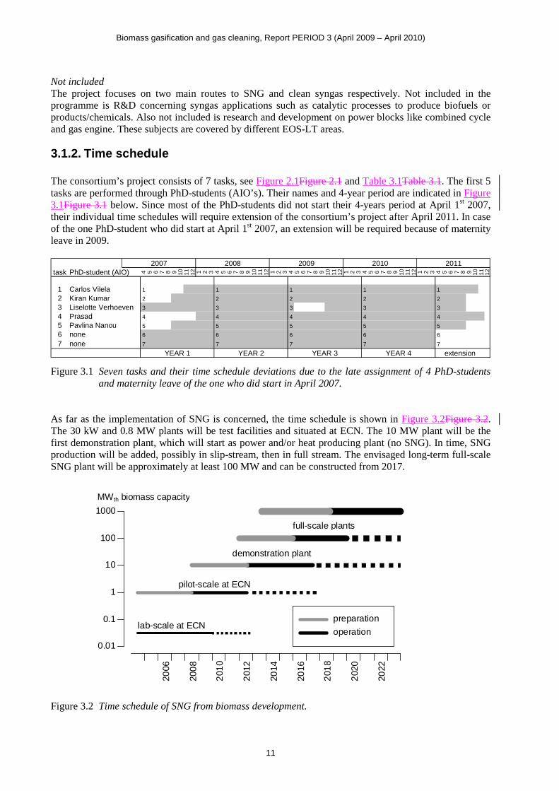
and maternity leave of the one who did start in April 2007. As far as the implementation of SNG is concerned, the time schedule is shown in Figure 3.2Figure 3.2. The 30 kW and 0.8 MW plants will be test facilities and situated at ECN. The 10 MW plant will be the first demonstration plant, which will start as power and/or heat producing plant (no SNG). In time, SNG production will be added, possibly in slip-stream, then in full stream. The envisaged long-term full-scale SNG plant will be approximately at least 100 MW and can be constructed from 2017.
Figure 3.2 Time schedule of SNG from biomass development.
2006
0.01
0.1
1
10
100
1000
MWth biomass capacity
200
8
201
0
201
2
2014
2016
201
8
202
0
2022
lab-scale at ECN
pilot-scale at ECN
demonstration plant
full-scale plants
preparation
operation
Biomass gasification and gas cleaning, Report PERIOD 3 (April 2009 – April 2010)
12
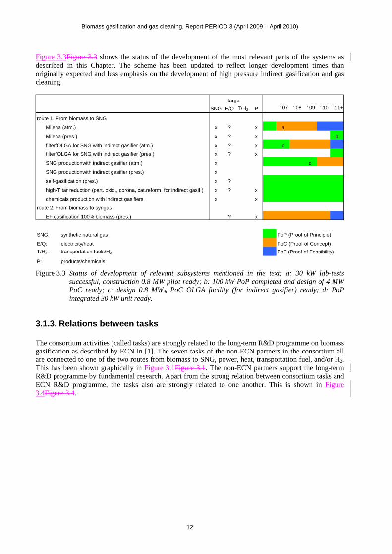
Figure 3.3Figure 3.3 shows the status of the development of the most relevant parts of the systems as described in this Chapter. The scheme has been updated to reflect longer development times than originally expected and less emphasis on the development of high pressure indirect gasification and gas cleaning.
target
SNG E/Q T/H2 P .' 07 .' 08 .' 09 .' 10 .' 11+
route 1. From biomass to SNG
Milena (atm.) x ? x a
Milena (pres.) x ? x b
filter/OLGA for SNG with indirect gasifier (atm.) x ? x c
filter/OLGA for SNG with indirect gasifier (pres.) x ? x
SNG productionwith indirect gasifier (atm.) x d
SNG productionwith indirect gasifier (pres.) x
self-gasification (pres.) x ?
high-T tar reduction (part. oxid., corona, cat.reform. for indirect gasif.) x ? x
chemicals production with indirect gasifiers x x
route 2. From biomass to syngas
EF gasification 100% biomass (pres.) ? x
SNG: synthetic natural gas PoP (Proof of Principle)
E/Q: electricity/heat PoC (Proof of Concept)
T/H2: transportation fuels/H2 PoF (Proof of Feasibility)
P: products/chemicals
Figure 3.3 Status of development of relevant subsystems mentioned in the text; a: 30 kW lab-tests successful, construction 0.8 MW pilot ready; b: 100 kW PoP completed and design of 4 MW PoC ready; c: design 0.8 MWth PoC OLGA facility (for indirect gasifier) ready; d: PoP integrated 30 kW unit ready.
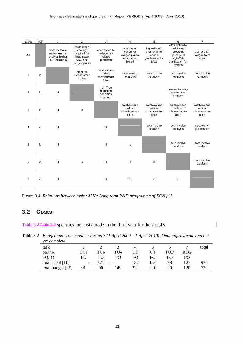
3.1.3. Relations between tasks The consortium activities (called tasks) are strongly related to the long-term R&D programme on biomass gasification as described by ECN in [1]. The seven tasks of the non-ECN partners in the consortium all are connected to one of the two routes from biomass to SNG, power, heat, transportation fuel, and/or H2. This has been shown graphically in Figure 3.1Figure 3.1. The non-ECN partners support the long-term R&D programme by fundamental research. Apart from the strong relation between consortium tasks and ECN R&D programme, the tasks also are strongly related to one another. This is shown in Figure 3.4Figure 3.4.
Biomass gasification and gas cleaning, Report PERIOD 3 (April 2009 – April 2010)
13
tasks MJP 1 2 3 4 5 6 7
MJP
more methane and/or less tar enables higher SNG efficiency
reliable gas cooling
required for large-scale SNG and
syngas plants
offer option to reduce tar-
related problems
alternative option for
syngas plants for imported
bio-oil
high-efficient alternative for
indirect gasification for
SNG
offer option to reduce tar problem,
go/nogo of high-CH4
gasification for syngas
go/nogo for syngas from
bio-oil
1 id other tar
means other fouling
catalysis and radical
chemistry are alike
both involve catalysis
both involve catalysis
both involve catalysis
both involve catalysis
2 id id
high-T tar reduction simplifies cooling
less/no tar may solve cooling
problem
3 id id id
catalysis and radical
chemistry are alike
catalysis and radical
chemistry are alike
catalysis and radical
chemistry are alike
catalysis and radical
chemistry are alike
4 id id id both involve
catalysis both involve
catalysis catalytic oil gasification
5 id id id id both involve
catalysis both involve
catalysis
6 id id id id id id both involve
catalysis
7 id id id id id id
Figure 3.4 Relations between tasks; MJP: Long-term R&D programme of ECN [1].
3.2 Costs Table 3.2Table 3.2 specifies the costs made in the third year for the 7 tasks. Table 3.2 Budget and costs made in Period 3 (1 April 2009 – 1 April 2010). Data approximate and not
yet complete. task 1 2 3 4 5 6 7 total partner TUe TUe TUe UT UT TUD BTG FO/IO FO FO FO FO FO FO FO total spent [k€] --- 371 --- 187 154 98 127 936 total budget [k€] 91 90 149 90 90 90 120 720
Biomass gasification and gas cleaning, Report PERIOD 3 (April 2009 – April 2010)
14
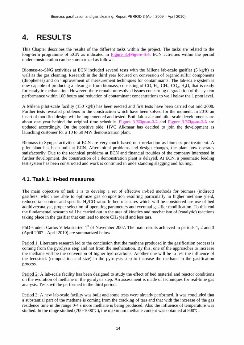
4. RESULTS This Chapter describes the results of the different tasks within the project. The tasks are related to the long-term programme of ECN as indicated in Figure 3.4Figure 3.4. ECN activities within the period under consideration can be summarized as follows. Biomass-to-SNG activities at ECN included several tests with the Milena lab-scale gasifier (5 kg/h) as well as the gas cleaning. Research in the third year focused on conversion of organic sulfur components (thiophenes) and on improvement of measurement techniques for contaminants. The lab-scale system is now capable of producing a clean gas from biomass, consisting of CO, H2, CH4, CO2, H2O, that is ready for catalytic methanation. However, there remain unresolved issues concerning degradation of the system performance within 100 hours and reduction of contaminant concentrations to well below the 1 ppm level. A Milena pilot-scale facility (150 kg/h) has been erected and first tests have been carried out mid 2008. Further tests revealed problems in the construction which have been solved for the moment. In 2010 an insert of modified design will be implemented and tested. Both lab-scale and pilot-scale developments are about one year behind the original time schedule. Figure 3.2Figure 3.2 and Figure 3.3Figure 3.3 are updated accordingly. On the positive side, HVC Alkmaar has decided to join the development as launching customer for a 10 to 50 MW demonstration plant. Biomass-to-Syngas activities at ECN are very much based on torrefaction as biomass pre-treatment. A pilot plant has been built at ECN. After initial problems and design changes, the plant now operates satisfactorily. Due to the technical problems at ECN and financial troubles of the company interested in further development, the construction of a demonstration plant is delayed. At ECN, a pneumatic feeding test system has been constructed and work is continued in understanding slagging and fouling.
4.1. Task 1: in-bed measures The main objective of task 1 is to develop a set of effective in-bed methods for biomass (indirect) gasifiers, which are able to optimize gas composition resulting particularly in higher methane yield, reduced tar content and specific H2/CO ratio. In-bed measures which will be considered are use of bed additive/catalyst, proper selection of operating parameters and eventual gasifier modification. To this end the fundamental research will be carried out in the area of kinetics and mechanism of (catalytic) reactions taking place in the gasifier that can lead to more CH4 yield and less tars. PhD-student Carlos Vilela started 1st of November 2007. The main results achieved in periods 1, 2 and 3 (April 2007 - April 2010) are summarized below. Period 1: Literature research led to the conclusion that the methane produced in the gasification process is coming from the pyrolysis step and not from the methanation. By this, one of the approaches to increase the methane will be the conversion of higher hydrocarbons. Another one will be to test the influence of the feedstock (composition and size) in the pyrolysis step to increase the methane in the gasification process. Period 2: A lab-scale facility has been designed to study the effect of bed material and reactor conditions on the evolution of methane in the pyrolysis step. An assessment is made of techniques for real-time gas analysis. Tests will be performed in the third period. Period 3: A new lab-scale facility was built and some tests were already performed. It was concluded that a substantial part of the methane is coming from the cracking of tars and that with the increase of the gas residence time in the range 0-4 s more methane is being produced. Also the influence of temperature was studied. In the range studied (700-1000ºC), the maximum methane content was obtained at 900ºC.
Biomass gasification and gas cleaning, Report PERIOD 3 (April 2009 – April 2010)
15
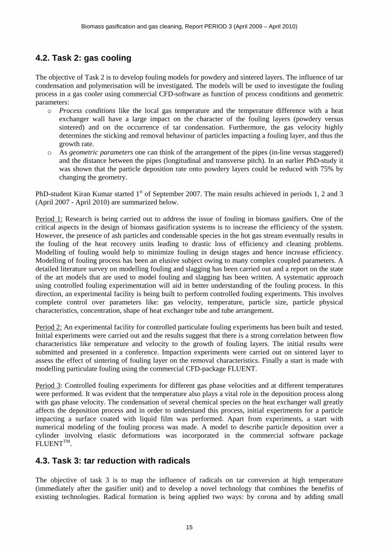
4.2. Task 2: gas cooling The objective of Task 2 is to develop fouling models for powdery and sintered layers. The influence of tar condensation and polymerisation will be investigated. The models will be used to investigate the fouling process in a gas cooler using commercial CFD-software as function of process conditions and geometric parameters:
o Process conditions like the local gas temperature and the temperature difference with a heat exchanger wall have a large impact on the character of the fouling layers (powdery versus sintered) and on the occurrence of tar condensation. Furthermore, the gas velocity highly determines the sticking and removal behaviour of particles impacting a fouling layer, and thus the growth rate.
o As geometric parameters one can think of the arrangement of the pipes (in-line versus staggered) and the distance between the pipes (longitudinal and transverse pitch). In an earlier PhD-study it was shown that the particle deposition rate onto powdery layers could be reduced with 75% by changing the geometry.
PhD-student Kiran Kumar started 1st of September 2007. The main results achieved in periods 1, 2 and 3 (April 2007 - April 2010) are summarized below. Period 1: Research is being carried out to address the issue of fouling in biomass gasifiers. One of the critical aspects in the design of biomass gasification systems is to increase the efficiency of the system. However, the presence of ash particles and condensable species in the hot gas stream eventually results in the fouling of the heat recovery units leading to drastic loss of efficiency and cleaning problems. Modelling of fouling would help to minimize fouling in design stages and hence increase efficiency. Modelling of fouling process has been an elusive subject owing to many complex coupled parameters. A detailed literature survey on modelling fouling and slagging has been carried out and a report on the state of the art models that are used to model fouling and slagging has been written. A systematic approach using controlled fouling experimentation will aid in better understanding of the fouling process. In this direction, an experimental facility is being built to perform controlled fouling experiments. This involves complete control over parameters like: gas velocity, temperature, particle size, particle physical characteristics, concentration, shape of heat exchanger tube and tube arrangement. Period 2: An experimental facility for controlled particulate fouling experiments has been built and tested. Initial experiments were carried out and the results suggest that there is a strong correlation between flow characteristics like temperature and velocity to the growth of fouling layers. The initial results were submitted and presented in a conference. Impaction experiments were carried out on sintered layer to assess the effect of sintering of fouling layer on the removal characteristics. Finally a start is made with modelling particulate fouling using the commercial CFD-package FLUENT. Period 3: Controlled fouling experiments for different gas phase velocities and at different temperatures were performed. It was evident that the temperature also plays a vital role in the deposition process along with gas phase velocity. The condensation of several chemical species on the heat exchanger wall greatly affects the deposition process and in order to understand this process, initial experiments for a particle impacting a surface coated with liquid film was performed. Apart from experiments, a start with numerical modeling of the fouling process was made. A model to describe particle deposition over a cylinder involving elastic deformations was incorporated in the commercial software package FLUENTTM.
4.3. Task 3: tar reduction with radicals The objective of task 3 is to map the influence of radicals on tar conversion at high temperature (immediately after the gasifier unit) and to develop a novel technology that combines the benefits of existing technologies. Radical formation is being applied two ways: by corona and by adding small
Biomass gasification and gas cleaning, Report PERIOD 3 (April 2009 – April 2010)
16
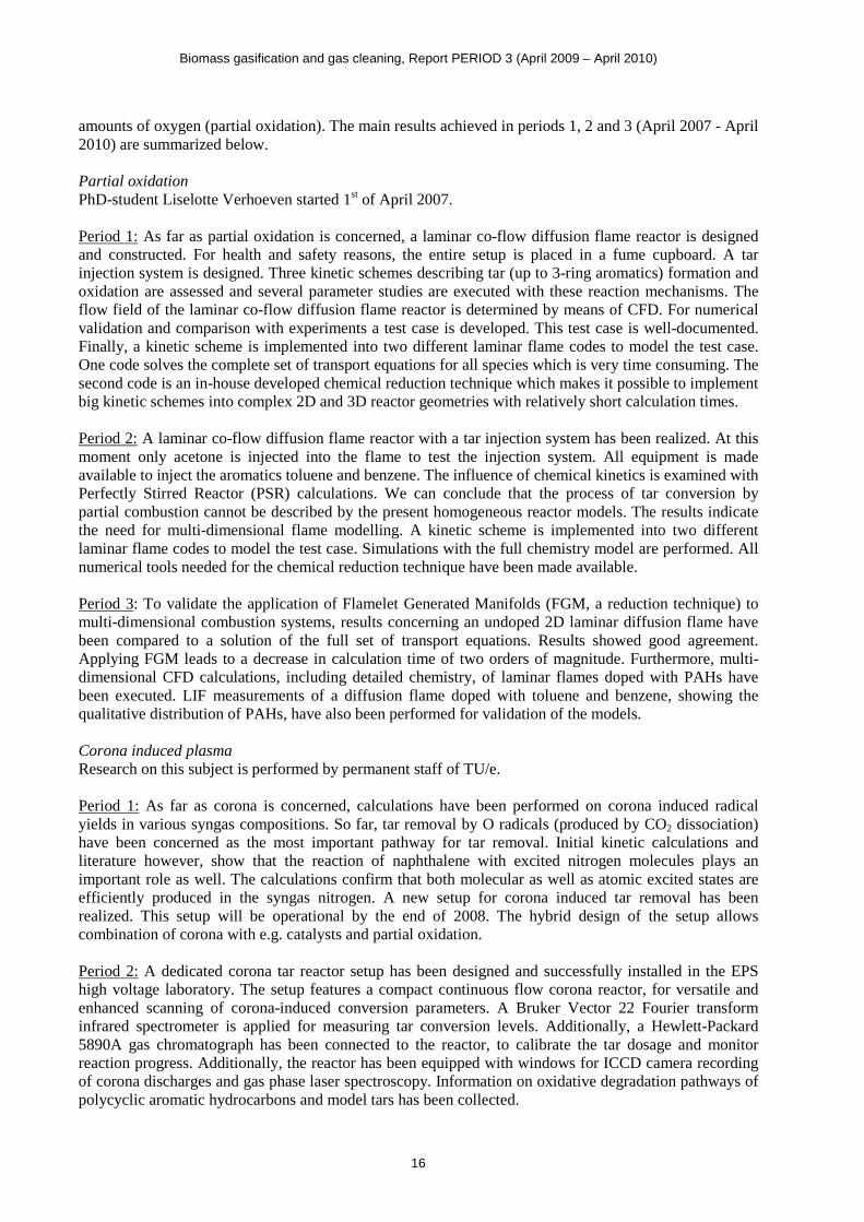
amounts of oxygen (partial oxidation). The main results achieved in periods 1, 2 and 3 (April 2007 - April 2010) are summarized below. Partial oxidation PhD-student Liselotte Verhoeven started 1st of April 2007. Period 1: As far as partial oxidation is concerned, a laminar co-flow diffusion flame reactor is designed and constructed. For health and safety reasons, the entire setup is placed in a fume cupboard. A tar injection system is designed. Three kinetic schemes describing tar (up to 3-ring aromatics) formation and oxidation are assessed and several parameter studies are executed with these reaction mechanisms. The flow field of the laminar co-flow diffusion flame reactor is determined by means of CFD. For numerical validation and comparison with experiments a test case is developed. This test case is well-documented. Finally, a kinetic scheme is implemented into two different laminar flame codes to model the test case. One code solves the complete set of transport equations for all species which is very time consuming. The second code is an in-house developed chemical reduction technique which makes it possible to implement big kinetic schemes into complex 2D and 3D reactor geometries with relatively short calculation times. Period 2: A laminar co-flow diffusion flame reactor with a tar injection system has been realized. At this moment only acetone is injected into the flame to test the injection system. All equipment is made available to inject the aromatics toluene and benzene. The influence of chemical kinetics is examined with Perfectly Stirred Reactor (PSR) calculations. We can conclude that the process of tar conversion by partial combustion cannot be described by the present homogeneous reactor models. The results indicate the need for multi-dimensional flame modelling. A kinetic scheme is implemented into two different laminar flame codes to model the test case. Simulations with the full chemistry model are performed. All numerical tools needed for the chemical reduction technique have been made available. Period 3: To validate the application of Flamelet Generated Manifolds (FGM, a reduction technique) to multi-dimensional combustion systems, results concerning an undoped 2D laminar diffusion flame have been compared to a solution of the full set of transport equations. Results showed good agreement. Applying FGM leads to a decrease in calculation time of two orders of magnitude. Furthermore, multi-dimensional CFD calculations, including detailed chemistry, of laminar flames doped with PAHs have been executed. LIF measurements of a diffusion flame doped with toluene and benzene, showing the qualitative distribution of PAHs, have also been performed for validation of the models. Corona induced plasma Research on this subject is performed by permanent staff of TU/e. Period 1: As far as corona is concerned, calculations have been performed on corona induced radical yields in various syngas compositions. So far, tar removal by O radicals (produced by CO2 dissociation) have been concerned as the most important pathway for tar removal. Initial kinetic calculations and literature however, show that the reaction of naphthalene with excited nitrogen molecules plays an important role as well. The calculations confirm that both molecular as well as atomic excited states are efficiently produced in the syngas nitrogen. A new setup for corona induced tar removal has been realized. This setup will be operational by the end of 2008. The hybrid design of the setup allows combination of corona with e.g. catalysts and partial oxidation. Period 2: A dedicated corona tar reactor setup has been designed and successfully installed in the EPS high voltage laboratory. The setup features a compact continuous flow corona reactor, for versatile and enhanced scanning of corona-induced conversion parameters. A Bruker Vector 22 Fourier transform infrared spectrometer is applied for measuring tar conversion levels. Additionally, a Hewlett-Packard 5890A gas chromatograph has been connected to the reactor, to calibrate the tar dosage and monitor reaction progress. Additionally, the reactor has been equipped with windows for ICCD camera recording of corona discharges and gas phase laser spectroscopy. Information on oxidative degradation pathways of polycyclic aromatic hydrocarbons and model tars has been collected.
Biomass gasification and gas cleaning, Report PERIOD 3 (April 2009 – April 2010)
17
Period 3: The experimental setups have been extended with following diagnostic tools: (i) in-situ plasma fast imaging and spectroscopy, (ii) online gas chromatography-mass spectrometry, and (iii) online Fourier Transform Infrared Spectroscopy. The influence of many reaction parameters on corona induced tar conversion and degradation products is under investigation. A Shimadzu QP2010 Plus gas chromatograph-mass spectrometer has been installed for identification of the complex corona-induced tar degradation product spectrum. Specific issues comprise the influence of hydrogen and excited states of nitrogen, additives like noble gases & nitrous oxide. Further, a new high voltage circuit has been designed for production of steep high voltage pulses, and optical emission spectroscopy will be applied for gaining insight in active radical species, together with fast CCD imaging of the plasma.
4.4. Task 4: catalytic oil gasification The possibility of producing syngas by catalytic gasification of bio-oil at low temperature (~ 800°C) has been shown in previous research. There are, however, still unresolved problems in the catalyst and reactor design of which degradation is an important issue (see “background”). The goal of task 4 is to develop a heat integrated reactor concept for low temperature catalytic gasification of bio-oil to synthesis gas that minimizes degeneration of the catalyst and ensures auto-thermal operation. Catalyst development is continued in other programs. A fundamental approach is taken in the design of the reactor starting from first principles knowledge on mass & heat transfer, mixing and chemical kinetics. PhD-student Prasad started 1st of January 2008. The main results achieved in periods 1, 2 and 3 (April 2007 - April 2010) are summarized below. Period 1: Due to delayed appointment of the PhD student, only 3 months of work were performed. In this short period a good start was made with a literature review and construction of an experimental set-up for investigating oil atomization. Period 2: Evaporation of pyrolysis oil was studied at different heating rates (1 to 106 °C/min) between 500 and 850°C (reactor temperature). The carbon distribution to products such as vapours (tar), gases and char was measured using an ultrasonic atomizer (which produces droplet size dp,max = 117 µm) and a needle atomizer (which produces ~ 1.5 mm droplets). Lower heating rates (1 to 100 °C/min) produce ~25% of char on carbon basis whereas higher heating rates (106 °C/min) limit char production considerably (~8%). The char produced at lower temperatures (500°C) is more reactive than at higher temperatures. Results are summarized in a paper published in AIChE Journal. Period 3: Evaporation experiments of biomass fast pyrolysis oil and its aqueous fractions at low (TGA-10 °C/min, glass tube-100 °C/min) and high (atomization ~106 °C/min) heating rates are performed. Slow heating of pyrolysis oil produced ~28% char (on carbon basis) while atomization of oil droplets (~117 µm) produced ~ 9% char in the temperature range of 500-850°C. Aqueous fractions and glucose solutions also produced less char by evaporating at higher heating rates (~3% char) when compared to slower heating (~ 24% char). The results obtained show that not a single lumped components class in pyrolysis oil can be identified that is primarily responsible for the char formation. At low heating rate, higher concentrations of organics in the bioliquids result in higher char yields, which reveals that a certain fraction in the oil produce char with a reaction order higher than one (polymerization reactions). The measured trends in char yield can be described by a model in which certain fraction of oil is converted by two parallel reactions to char and gas/vapour.
Biomass gasification and gas cleaning, Report PERIOD 3 (April 2009 – April 2010)
18
4.5. Task 5: self-gasification The principle that uses alkali metals present in the biomass as catalyst for the production of methane-rich gas, is proven by previous coal experience and screening tests by the University of Twente. The objective of task 5 is to design, construct and test a gasifier that: - provides the required contact between the reactants (biomass and intermediate gases and vapours) and
the alkali metals for the catalytic activity and, - creates, selectively, the required high alkali metal content in the reactor using only the ashes from the
feedstock while preventing accumulation of other ash components, A fundamental approach is taken in the design of this reactor starting from first principles knowledge on mass & heat transfer, mixing and chemical kinetics. PhD-student Pavlina Nanou started 1st of September 2007. The main results achieved in periods 1, 2 and 3 (April 2007 - April 2010) are summarized below. Period 1: Due to the delayed appointment of the PhD student, only 7 months of work were performed. In this short period a good start was made with a literature review and high throughput experimentation to scan the operating window. The first results show that high amounts of methane (up to 30% on carbon basis, compared to 10 to 14% in “conventional” technology gasifiers) can be produced under typical self-gasification of p>100 bar and 800°C. Surprisingly, no higher hydrocarbons were found. In the next phases of the project, the work will be focused around: i) investigating tar formation in the self-gasification process and ii) understanding the catalytic effect of ash(components). Period 2: In the second period, screening in micro reactors has been completed. The results show that methane formation from wood is possible under self-gasification conditions and at amounts even higher than equilibrium. Impregnated KOH enhances gasification rate of char and from TGA measurements it was noted to lower the pyrolysis temperature of the wood. A continuous set-up for studying the catalytic effect of ashes/minerals and commercial catalysts is installed and ready to start a measurement campaign. Period 3: After the initial screening experiments, the methane yield has been investigated at elevated pressures using potassium and ruthenium model catalysts. It was shown that the methane yield is lower when using a catalyst than without which shows that the high methane yield is obtained due to the primary conversion rather than the secondary. On a lab scale, higher methane amounts are being produced compared to other biomass technologies. A model has been built which evaluates two different base cases for self gasification from an efficiency point of view. Initially, the process operating regime boundaries have been evaluated where high methane yields are obtained and no thermodynamic coke is being formed.
4.6. Task 6: catalytic (tar) reforming If tars are removed by a catalyst within or downstream the gasifier, tar-related cooling problems are eliminated and the energy content of the tars is retained. It even is possible to not only remove tars at high temperature, but also to reform other hydrocarbons. This enables the production of a syngas (H2 and CO) without having to increase the temperature. In principle a catalytic system is simpler than a scrubber, especially when no reactant is to be added. The only task for the tar cracking catalyst is to convert the tar species to their equilibrium concentrations. It is, though, naive to think that this is easily established and cheap. The purpose of task 6 is to gain insight in this process. The primary aim is to make an extensive survey of the developments in the area of catalysts applied during gasification of biomass. Published results need to be critically reviewed regarding their possibilities of feasible technology implementation. Also, a comparison with non-catalytic methods will be part of the study. The main results achieved in periods 1, 2 and 3 (April 2007 - April 2010) are summarized below.
Biomass gasification and gas cleaning, Report PERIOD 3 (April 2009 – April 2010)
19
Period 1: Results of the first year include an overview of existing catalytic reformers and running development programmes. Whereas olivine seems to be a good choice for in-bed catalytic tar removal, downstream reforming mostly involves Ni-based catalysts. Current developments focus on improving sulfur sensitivity and reducing coking. Alternative catalysts are reduced iron oxide, Co/Rh/Ru/Pt containing catalysts with promoting functionalities, activated alumina and (doped) ZrO2-alumina based catalysts. Among the Ni-based tar reformers, monolithic reactors seem attractive because of their robustness concerning dust loading. This however, has not been proven satisfactorily yet. Combined reforming and filtering offers another option to deal with tar reforming in a dust-laden gas. Catalytic gas cleaning is a serious technology option in process routes for the production of SNG and syngas. Three configurations have been discussed regarding tars: - virtually total tar and hydrocarbon cleanup for pure hydrogen gas / no hydrocarbon containing
syngas; - selective clean-up of all tars, but minimizing methane reforming for SNG production; - selective heavy tar cleanup for lower temperature gas cleaning using e.g. OLGA technology, thereby
preventing serious fouling of the cooler upstream. In this respect, longer term proven demonstration of Ni-based monoliths directly situated downstream of the gasifier would be interesting to establish this technology as feasible. Furthermore, the development of non-Ni based monoliths could be even better. Due to the uncertainty on long term solids depositing on such monoliths, combining the function of particulate matter removal and tar (/ammonia) conversion is highly interesting in view of the potential cost reduction it would imply. However, there are still developments in catalytic material testing and improving with respect to sulphur tolerance as well as trace (alkali) metal related degradation resistance. Furthermore, in this respect a study is needed towards the fate of C2 components after catalytic tar reforming using the filters. Also, an investigation of the fate of a specific sulphur compound (thiophene) that is found in indirect gasification related to catalyst behaviour is needed. The research at ECN done on a high-temperature process called TREC has shown that intriguing phenomena take place there in an analogue concept where dust, tar as well as sulfur species are seriously reduced. An investigation towards novel sorbents optimizing the (selective) removal of especially tars in the three abovementioned concepts in such an application with char included is for sure worth to investigate and has been recognized as a priority route to follow. Results of period 1 have led to the decision to continue R&D in Task 6 on “catalytic (tar) reforming”, focusing on two subjects:
- combined dust/tar removal (a catalytic reforming filter) - selective heavy tar reduction for easy cooling
Period 2: At the end of period 1, a ‘go’ decision was taken for this task. A bilateral meeting between ECN and TU Delft in September 2008 led to a more precise formulation of this project task for the remaining years. It has become clear that integration of hot gas ceramic filtration and catalytic reforming will not be possible within this programme due to continuing Intellectual Property Rights issues with the company Pall (Schumacher, Crailsheim, Germany). An alternative programme was therefore proposed in which TU Delft will focus its study primarily on the conversion behaviour of selected heavy tar compounds based on comparatively cheap (natural) bed materials. Gas cooling of the raw product gas from the Milena gasifier is prone to fouling caused by condensation of the heavier tar species. When these are selectively converted to lower molecular weight, less problematic tars (lower dew points) before the cooling then longer term sustained operation of the cooler is ensured. This is of importance for the development of an improved SNG production chain. The use of cheap materials has preference in view of the costs associated with an added process unit. From the
Biomass gasification and gas cleaning, Report PERIOD 3 (April 2009 – April 2010)
20
literature not much fundamental kinetics data concerning these problematic species could be retrieved. A programme was thus designed to systematically study this conversion behaviour with gases that are good models for the gas derived from the Milena gasifier. In a later stage then real gas tests can be carried out. In this second year, the existing high temperature gas cleaning unit (HTGCU) was adapted to allow gas and tar species measurements before and after a quartz reactor. The unit was allowed automized operation and the temperature control was improved. Furthermore, a dedicated design of a tar evaporation unit was made allowing different heavy polyaromatic species to be dosed in concentrations representative for Milena technology based gasification. An MSc. Student was appointed as student assistant to work on this project closely together with ECN next to support from the permanent staff and PhD students. The student made an inventory of possible model heavy tar compounds and catalytic materials as well as process conditions (temperature, residence time). Period 3: in this period 3, systemic experiments were expected to be carried out on HTGCU in order to investigate the effect of different operation parameters (residence time, gas composition and reaction temperature) and bed materials (olivine and iron silicate) on tar cracking. So far limited experimental results have been achieved due to the heating problem in HTGCU.
4.7. Task 7: syngas production through pyrolysis The aim of task 7 is to develop technology for (close-coupled) autothermal catalytic reforming of pyrolysis (vapours) for the production of syngas at relatively low temperature. Focus is on overall performance, soot formation, and catalyst reactor. This activity does not include a PhD. The main results achieved in periods 1, 2 and 3 (April 2007 - April 2010) are summarized below. Period 1: By testing a number of burners/mixers in a cold flow set-up and a hot set-up, partial oxidation (PO) chambers are developed. The most suitable PO-chamber for catalytic gasification of pyrolysis vapours consists of a static mixer and a swirl body. The most suitable PO-chamber for catalytic gasification of pyrolysis oil consists of an air atomizer and a steam jet. As for the option to feed pyrolysis oil into an entrained flow gasifier for direct syngas production, technical options have been described. The main question remains the ash behaviour. The oil seems to have sufficient ash to generate serious problems in slagging within the reactor as well as fouling in the downstream cooler. Since tests in the lab-scale LCS (simulator) at ECN have been done and planned in a separate project, it has been decided not to continue this part of task 7. Task 7 will continue the development of partial oxidation of oil as well as oil-vapour, followed by catalytic reforming. Period 2: Catalytic gasification of pyrolysis vapours and catalytic gasification of pyrolysis oil show both a sufficient reforming of methane and sufficient cracking of tars. A standard Ni-based catalyst has been used. Also for both processes the practically obtained test values are showing similar trends as predicted values when reaching equilibrium. Period 3: The BTG staged gasification setup was used to determine the performance of four different catalysts (three monolith type and one a fixed bed of spoked-wheel type catalyst) for methane and tar conversion at space velocities near those used commercially. Two of the monolith catalysts were also tested in series. The monolith catalysts show significantly higher activity than the fixed bed catalyst. The ML-B catalyst seems to have the highest naphtalene and methane conversion of the catalysts considered. The combination of the ML-B and ML-C catalysts yielded the best results, partly because the space velocity
Biomass gasification and gas cleaning, Report PERIOD 3 (April 2009 – April 2010)
21
was halved in comparison with the other tests). The lowest tar concentration obtained (~180 mg/Nm3, for the ML-BC combination) is considered still too high, while the overall energetic efficiency is on the low side (max. 64%, for the ML-C catalyst). Future research should be aimed primarily to improve these overall results. The tar concentration can be decreased significantly by increasing the steam reforming reactions. This can be achieved by either using a feedstock with higher moisture content, or by adding steam directly to the gasifier. Using a feedstock with higher moisture content would simultaneously improve the overall energetic efficiency. The overall energetic efficiency could also be improved significantly by decreasing the amount of air to the gasifier. It is normally expected that in this case more catalyst will be required to prevent high tar concentrations.
Biomass gasification and gas cleaning, Report PERIOD 3 (April 2009 – April 2010)
22
5. PROGRESS
5.1. Technical and organisational problems There were no major technical and organisational problems encountered in Period 3 (April 2009 - April 2010).
5.2. Deviations from original plan The original plan assumed PhD-students to start 1st of April 2007. This only succeeded for one of the five PhD-students planned. Although all PhD-student actually started within Period 1, the average delay is over 5 months. The one PhD student who actually started on the 1st of April 2007 will incur a similar delay because of maternity leave in 2009.
5.3. Budget changes Due to the delay in assigning PhD-students, budgets have not been spent according to plan in the first year. In the second and third year there were no changes in the budgets as compared to the project proposals.
6. CONTRIBUTION TO EOS LONG TERM
OBJECTIVES Follows when all 4 parts (1 year periods) of the project will have been completed in 2011. For the expected contribution see the original project proposal, chapter 5.
7. OUTCOME INDICATORS Follows when all 4 parts (1 year periods) of the project will have been completed in 2011.
8. REFERENCES [1] J. W. Erisman, J. H. A. Kiel, R. van Ree, J. Beesteheerde and A. van der Drift: Long term
programme on biomass and coal, 06-34 (29 September 2006), 73 p. (2006). [2] SenterNovem: Lange termijn EOS-onderzoeksprogramma's, 28 juni 2004, SenterNovem, Utrecht,
99 p. (2004). [3] SenterNovem: EOS long-term Energy strategy, the Netherlands, November 2004, SenterNovem,
Utrecht, 102 p. (2004). [4] J. Koppejan and P. D. M. de Boer - Meulman: De verwachte beschikbaarheid van biomassa in
2010, SenterNovem, Utrecht, Rapportnummer 2DEN05.16 (2005).