Baureihe E 44 (144) - static.maerklin.de · Digital-Elektronik bietet: • Wahlweise...
43
Baureihe E 44 (144)
Transcript of Baureihe E 44 (144) - static.maerklin.de · Digital-Elektronik bietet: • Wahlweise...
Baureihe E 44 (144)
2 Betrieb Seite 9 Operation Page 16 Fonctionnement Page 23 Exploitatie Blz. 30
1 Exploitation Vorbild Seite 5 Prototype Page 6 dans le réel Page 7 Grootbedrijf Blz. 8
3 Betrieb auf Operation on Exploitation Bedrijf opder Anlage Seite 37 a layout Page 37 sur réseau Page 37 een modelbaan Blz. 37
4 Wartung Seite 39 Maintenance Page 39 Entretien Page 39 Onderhoud Blz. 39
3
1 Vorbild
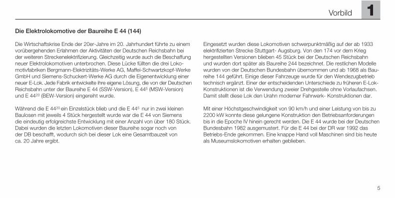
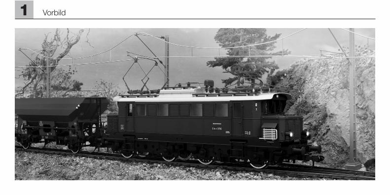
Die Elektrolokomotive der Baureihe E 44 (144)
Die Wirtschaftskrise Ende der 20er-Jahre im 20. Jahrhundert führte zu einemvorübergehenden Erlahmen der Aktivitäten der Deutschen Reichsbahn beider weiteren Streckenelektrifizierung. Gleichzeitig wurde auch die Beschaffungneuer Elektrolokomotiven unterbrochen. Diese Lücke füllten die drei Loko-motivfabriken Bergmann-Elektrizitäts-Werke AG, Maffei-Schwartzkopf-WerkeGmbH und Siemens-Schuckert-Werke AG durch die Eigenentwicklung einerneuer E-Lok. Jede Fabrik entwickelte ihre eigene Lösung, die von der DeutschenReichsbahn unter der Baureihe E 44 (SSW-Version), E 445 (MSW-Version)und E 4420 (BEW-Version) eingereiht wurde.
Während die E 4420 ein Einzelstück blieb und die E 445 nur in zwei kleinenBaulosen mit jeweils 4 Stück hergestellt wurde war die E 44 von Siemens die eindeutig erfolgreichste Entwicklung mit einer Anzahl von über 180 Stück.Dabei wurden die letzten Lokomotiven dieser Baureihe sogar noch von der DB beschafft, wodurch sich bei dieser Lok eine Gesamtbauzeit von ca. 20 Jahre ergibt.
Eingesetzt wurden diese Lokomotiven schwerpunktmäßig auf der ab 1933elektrifizierten Strecke Stuttgart- Augsburg. Von den 174 vor dem Krieg hergestellten Versionen blieben 45 Stück bei der Deutschen Reichsbahn und wurden dort später als Baureihe 244 bezeichnet. Die restlichen Modellewurden von der Deutschen Bundesbahn übernommen und ab 1968 als Bau-reihe 144 geführt. Einige dieser Fahrzeuge wurde für den Wendezugbetriebtechnisch ergänzt. Einer der entscheidenden Unterschiede zu früheren E-Lok-Konstruktionen ist die Verwendung zweier Drehgestelle ohne Vorlaufachsen.Damit stellt diese Lok den Urahn moderner Fahrwerk- Konstruktionen dar.
Mit einer Höchstgeschwindigkeit von 90 km/h und einer Leistung von bis zu2200 kW konnte diese gelungene Konstruktion den Betriebsanforderungenbis in die Epoche IV hinein gerecht werden. Die E 44 wurde bei der DeutschenBundesbahn 1982 ausgemustert. Für die E 44 bei der DR war 1992 dasBetriebs-Ende gekommen. Eine knappe Hand voll Maschinen sind bis heuteals Museumslokomotiven erhalten geblieben.
1
5
Vorbild
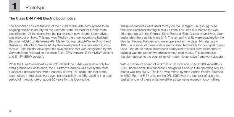
The Class E 44 (144) Electric Locomotive
The economic crisis at the end of the 1920s in the 20th century lead to anongoing decline in activity on the German State Railroad for further routeelectrification. At the same time the purchase of new electric locomotives was also put on hold. This gap was filled by the three locomotive buildersBergmann-Elektrizitäts-Werke AG, Maffei- Schwartzkopf-Werke GmbH andSiemens- Schuckert- Werke AG by the development of a new electric loco-motive. Each builder developed his own solution that was designated by theGerman State Railroad as the class E 44 (SSW version), E 445 (MSW version)and E 4420 (BEW version).
While the E 4420 remained a one-off unit and the E 445 was built in only twosmall groups of 4 units each, the E 44 from Siemens was clearly the mostsuccessful development with a quantity of over 180 units. The last of thelocomotives in this class were even purchased by the DB, resulting in a totalperiod of manufacture of about 20 years for this locomotive.
These locomotives were used mostly on the Stuttgart – Augsburg route that was electrified starting in 1933. Of the 174 units built before the war, 45 ended up with the German State Railroad (East Germany) and were laterdesignated there as the class 244. The remaining units were acquired by theGerman Federal Railroad and were operated as the class 144 starting in1968. A number of these units were modified technically for push/pull opera-tions. One of the critical differences compared to earlier electric locomotivebuilding was the use of two trucks without pilot trucks. This locomotive thereby represents the beginnings of modern locomotive framework designs.
With a maximum speed of 90 km/h or 56 mph and up to 2,200 kilowatts or2,950 horsepower, this successful design was able to fulfill operating require-ments well into Era IV. The E 44 was retired by the German Federal Railroadin 1982. For the E 44 units on the DR, 1992 was the last year of operation.Just a handful of these units are still in existence as museum locomotives.
6
1 Prototype
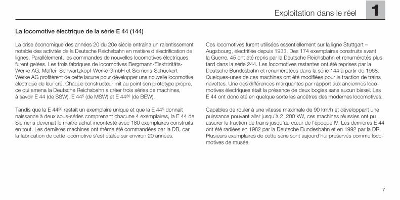
La locomotive électrique de la série E 44 (144)
La crise économique des années 20 du 20e siècle entraîna un ralentissementnotable des activités de la Deutsche Reichsbahn en matière d’électrification delignes. Parallèlement, les commandes de nouvelles locomotives électriquesfurent gelées. Les trois fabriques de locomotives Bergmann-Elektrizitäts-Werke AG, Maffei- Schwartzkopf-Werke GmbH et Siemens-Schuckert-Werke AG profitèrent de cette lacune pour développer une nouvelle locomotiveélectrique de leur crû. Chaque constructeur mit au point son prototype propre,ce qui amena la Deutsche Reichsbahn a créer trois séries de machines, à savoir E 44 (de SSW), E 445 (de MSW) et E 4420 (de BEW).
Tandis que la E 4420 restait un exemplaire unique et que la E 445 donnaitnaissance à deux sous-séries comprenant chacune 4 exemplaires, la E 44 deSiemens devenait le maître achat incontesté avec 180 exemplaires construitsen tout. Les dernières machines ont même été commandées par la DB, carla fabrication de cette locomotive s’est étalée sur environ 20 années.
Ces locomotives furent utilisées essentiellement sur la ligne Stuttgart – Augsbourg, électrifiée depuis 1933. Des 174 exemplaires construits avant la Guerre, 45 ont été repris par la Deutsche Reichsbahn et renumérotés plustard dans la série 244. Les locomotives restantes ont été reprises par laDeutsche Bundesbahn et renumérotées dans la série 144 à partir de 1968.Quelques-unes de ces machines ont été modifiées pour la traction de trainsnavettes. Une des différences marquantes par rapport aux anciennes loco-motives électriques était la présence de deux bogies sans aucun bissel. LesE 44 ont donc été en quelque sorte les ancêtres des modernes locomotives.
Capables de rouler à une vitesse maximale de 90 km/h et développant unepuissance pouvant aller jusqu’à 2 200 kW, ces machines réussies ont puassurer la traction de trains jusqu’au cœur de l’époque IV. Les dernières E 44ont été radiées en 1982 par la Deutsche Bundesbahn et en 1992 par la DR.Plusieurs exemplaires de cette série sont aujourd’hui préservés comme loco-motives de musée.
1
7
Exploitation dans le réel
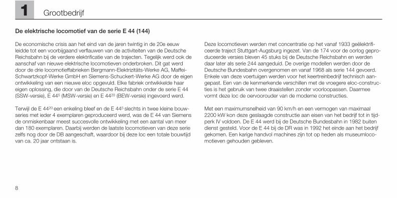
De elektrische locomotief van de serie E 44 (144)
De economische crisis aan het eind van de jaren twintig in de 20e eeuw leidde tot een voorbijgaand verflauwen van de activiteiten van de DeutscheReichsbahn bij de verdere elektrificatie van de trajecten. Tegelijk werd ook deaanschaf van nieuwe elektrische locomotieven onderbroken. Dit gat werddoor de drie locomotieffabrieken Bergmann-Elektrizitäts-Werke AG, Maffei-Schwartzkopf-Werke GmbH en Siemens-Schuckert-Werke AG door de eigenontwikkeling van een nieuwe eloc opgevuld. Elke fabriek ontwikkelde haareigen oplossing, die door van de Deutsche Reichsbahn onder de serie E 44(SSW-versie), E 445 (MSW-versie) en E 4420 (BEW-versie) ingevoerd werd.
Terwijl de E 4420 een enkeling bleef en de E 445 slechts in twee kleine bouw-series met ieder 4 exemplaren geproduceerd werd, was de E 44 van Siemensde onmiskenbaar meest succesvolle ontwikkeling met een aantal van meerdan 180 exemplaren. Daarbij werden de laatste locomotieven van deze seriezelfs nog door de DB aangeschaft, waardoor bij deze loc een totale bouwtijdvan ca. 20 jaar ontstaan is.
Deze locomotieven werden met concentratie op het vanaf 1933 geëlektrifi-ceerde traject Stuttgart-Augsburg ingezet. Van de 174 voor de oorlog gepro-duceerde versies bleven 45 stuks bij de Deutsche Reichsbahn en werdendaar later als serie 244 aangeduid. De overige modellen werden door deDeutsche Bundesbahn overgenomen en vanaf 1968 als serie 144 gevoerd.Enkele van deze voertuigen werden voor het keertreinbedrijf technisch aan-gepast. Een van de kenmerkende verschillen met de vroegere eloc-construc-ties is het gebruik van twee draaistellen zonder voorloopassen. Daarmeevormt deze loc de oervoorouder van de moderne constructies.
Met een maximumsnelheid van 90 km/h en een vermogen van maximaal2200 kW kon deze geslaagde constructie aan eisen van het bedrijf tot in tijd-perk IV voldoen. De E 44 werd bij de Deutsche Bundesbahn in 1982 buitendienst gesteld. Voor de E 44 bij de DR was in 1992 het einde aan het bedrijfgekomen. Een karige handvol machines zijn tot op heden als museumloco-motieven gehouden gebleven.
8
1 Grootbedrijf
2.1 Funktion
Diese Lok mit eingebauterDigital-Elektronik bietet:
• Wahlweise konventioneller Wech-selspannungs- (Transformer 32 VA)oder Gleichspannungs-Betrieb(max. 18 V=) sowie Märklin Delta(nur Delta Station 6607) oder Märklin Digital (Motorola-Format).Ein Betrieb mit Fahrgeräten andererSysteme (z.B. Impulsbreiten-steuerung, Betrieb mit der Central-Control 1 (6030) oder ähnlichemSystem) ist nicht möglich.
• Automatische Erkennung zwischenkonventionellem und Digital-/Delta-Betrieb. Die Auswahl zwischenWechselspannung und Gleich-spannung beim konventionellenBetrieb wird manuell auf der Platineeingestellt.
• 80 Digital- (4 Delta-) Adressenüber Codierschalter einstellbar.Eingestellte Adresse ab Werk: 44.
• Einstellbare Höchstgeschwindigkeit.
• Fahrtrichtungsabhängige Spitzen-beleuchtung im Digital- Betriebein-/ausschaltbar. Bei konventio-nellem Betrieb ist die Intensität derBeleuchtung geschwindigkeitsab-hängig. Bei Betrieb mit Delta Stati-on ist die Spitzenbeleuchtung dau-ernd eingeschaltet.
• Nur im Betrieb mit der Control-Unit 6021: EinschaltbareGeräuschelektronik zur geschwin-digkeitsabhängigen Wiedergabevon Vorbildgeräuschen.
• Nur im Betrieb mit der Control-Unit 6021: SchaltbaresGeräusch eines Signalhorns.
• Modell besitzt vorne und hintenjeweils eine Telexkupplung, mit der im Digitalbetrieb mit derControl-Unit 6021 Märklin Maxi-oder Profi 1-Modelle mit Klauen-kupplungen per Schaltbefehlabgekuppelt werden können. Bei Verwendung von Kupplungs-systemen anderer Hersteller sindBetriebsprobleme nicht ausge-schlossen.
• Befahrbarer Mindestradius: 600 mm. Empfohlener Mindest-radius: 1020 mm. Ein automati-sches An- oder Abkuppeln vonFahrzeugen ist in Kurven nichtmöglich. Beim Befahren von Kurven oder Weichen mit einemRadius von 600 mm muss dieGeschwindigkeit den Gegeben-heiten angepasst werden. Sonstsind Entgleisungen möglich.
• Dieses Modell ist für den Betriebauf Märklin Spur 1 Gleisen (Maxi-oder Profi 1) geeignet. Ein Betriebauf anderen Gleissystem erfolgtauf eigenes Risiko.
2
9
Betrieb
Betrieb
10
22.2 Einstellen der Betriebsart
oder Digital-/Delta-Adresse
Schritt 1:Dach abnehmen (Pfeifen heraus-drehen, Dach nach hinten schiebenund dann abnehmen. => S. 39).
Die Betriebsart oder die Digital-/Delta-Adresse wird an dem 10-fachCodierschalter auf der Digital-elektronik eingestellt.
Vorsicht! Den 10-fach Codier-schalter für die Betriebsart und für die Adresse auf der unterenDigital-Platine nicht mit dem 8-fach Codierschalter auf der oberen Soundplatine verwechseln!
2.2.1 Betriebsart einstellen
Schritt 2:Die analoge Betriebsart wird amSchalter 10 (Bezeichnung „0“) des10-fach Codierschalters eingestellt.
Schalter 10 (0) auf off: Wechselspannung
Schalter 10 (0) auf on: Gleichspannung
Die Betriebsart Märklin Digital bzw.Delta wird automatisch von der Elek-tronik erkannt.
Hinweis:Der Schalter 9 muss immer in Stel-lung „off“ stehen.
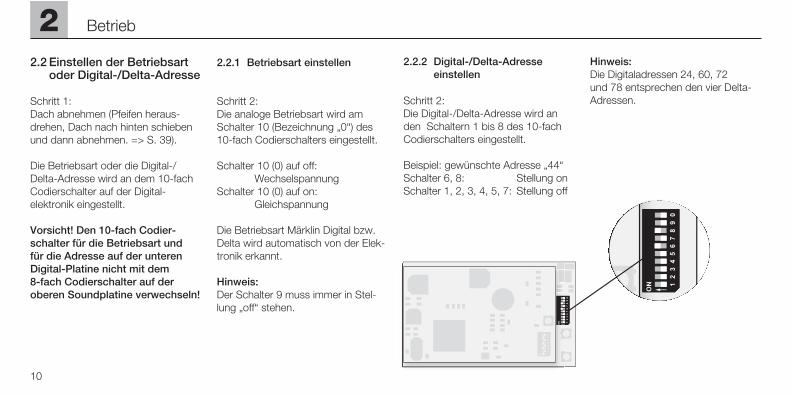
2.2.2 Digital-/Delta-Adresse einstellen
Schritt 2:Die Digital-/Delta-Adresse wird anden Schaltern 1 bis 8 des 10-fachCodierschalters eingestellt.
Beispiel: gewünschte Adresse „44“Schalter 6, 8: Stellung onSchalter 1, 2, 3, 4, 5, 7: Stellung off
Hinweis:Die Digitaladressen 24, 60, 72 und 78 entsprechen den vier Delta-Adressen.
2
11
Betrieb
Digital Digital Digital
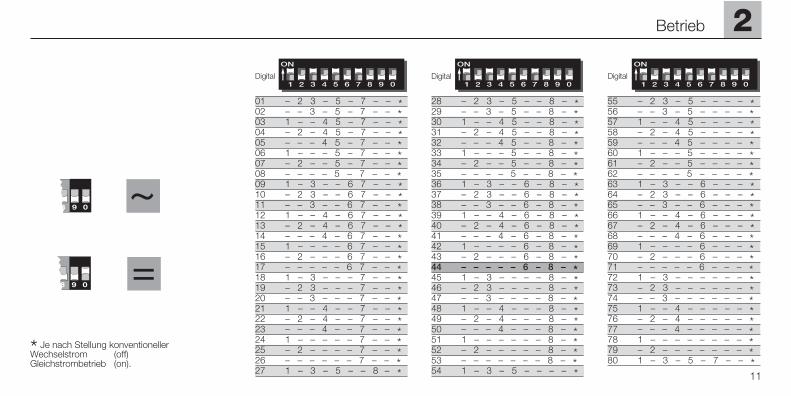
28 – 2 3 – 5 – – 8 – *29 – – 3 – 5 – – 8 – *30 1 – – 4 5 – – 8 – *31 – 2 – 4 5 – – 8 – *32 – – – 4 5 – – 8 – *33 1 – – – 5 – – 8 – *34 – 2 – – 5 – – 8 – *35 – – – – 5 – – 8 – *36 1 – 3 – – 6 – 8 – *37 – 2 3 – – 6 – 8 – *38 – – 3 – – 6 – 8 – *39 1 – – 4 – 6 – 8 – *40 – 2 – 4 – 6 – 8 – *41 – – – 4 – 6 – 8 – *42 1 – – – – 6 – 8 – *43 – 2 – – – 6 – 8 – *44 – – – – – 6 – 8 – *45 1 – 3 – – – – 8 – *46 – 2 3 – – – – 8 – *47 – – 3 – – – – 8 – *48 1 – – 4 – – – 8 – *49 – 2 – 4 – – – 8 – *50 – – – 4 – – – 8 – *51 1 – – – – – – 8 – *52 – 2 – – – – – 8 – *53 – – – – – – – 8 – *54 1 – 3 – 5 – – – – *
55 – 2 3 – 5 – – – – *56 – – 3 – 5 – – – – *57 1 – – 4 5 – – – – *58 – 2 – 4 5 – – – – *59 – – – 4 5 – – – – *60 1 – – – 5 – – – – *61 – 2 – – 5 – – – – *62 – – – – 5 – – – – *63 1 – 3 – – 6 – – – *64 – 2 3 – – 6 – – – *65 – – 3 – – 6 – – – *66 1 – – 4 – 6 – – – *67 – 2 – 4 – 6 – – – *68 – – – 4 – 6 – – – *69 1 – – – – 6 – – – *70 – 2 – – – 6 – – – *71 – – – – – 6 – – – *72 1 – 3 – – – – – – *73 – 2 3 – – – – – – *74 – – 3 – – – – – – *75 1 – – 4 – – – – – *76 – 2 – 4 – – – – – *77 – – – 4 – – – – – *78 1 – – – – – – – – *79 – 2 – – – – – – – *80 1 – 3 – 5 – 7 – – *
01 – 2 3 – 5 – 7 – – *02 – – 3 – 5 – 7 – – *03 1 – – 4 5 – 7 – – *04 – 2 – 4 5 – 7 – – *05 – – – 4 5 – 7 – – *06 1 – – – 5 – 7 – – *07 – 2 – – 5 – 7 – – *08 – – – – 5 – 7 – – *09 1 – 3 – – 6 7 – – *10 – 2 3 – – 6 7 – – *11 – – 3 – – 6 7 – – *12 1 – – 4 – 6 7 – – *13 – 2 – 4 – 6 7 – – *14 – – – 4 – 6 7 – – *15 1 – – – – 6 7 – – *16 – 2 – – – 6 7 – – *17 – – – – – 6 7 – – *18 1 – 3 – – – 7 – – *19 – 2 3 – – – 7 – – *20 – – 3 – – – 7 – – *21 1 – – 4 – – 7 – – *22 – 2 – 4 – – 7 – – *23 – – – 4 – – 7 – – *24 1 – – – – – 7 – – *25 – 2 – – – – 7 – – *26 – – – – – – 7 – – *27 1 – 3 – 5 – – 8 – *
* Je nach Stellung konventionellerWechselstrom (off)Gleichstrombetrieb (on).
~
=
9 0
9 0
2.3 Einstellen der Fahrparameter
1. Dach abnehmen (Pfeifen heraus-drehen, Dach nach hinten schiebenund dann abnehmen. => S. 39).
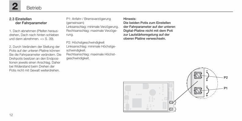
2. Durch Verändern der Stellung derPotis auf der unteren Platine könnenSie die Fahrparameter verändern. DieDrehpotis besitzen an den Endposi-tionen jeweils einen Anschlag. Daherbei Widerstand beim Drehen derPotis nicht mit Gewalt weiterdrehen.
P1: Anfahr-/ Bremsverzögerung(gemeinsam)Linksanschlag: minimale Verzögerung.Rechtsanschlag: maximale Verzöge-rung.
P2: HöchstgeschwindigkeitLinksanschlag: minimale Höchstge-schwindigkeit.Rechtsanschlag: maximale Höchst-geschwindigkeit.
Hinweis: Die beiden Potis zum Einstellender Fahrparameter auf der unterenDigital-Platine nicht mit dem Potizur Lautstärkeregelung auf deroberen Platine verwechseln.
12
2 Betrieb
P2
P1
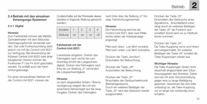
2.4 Betrieb mit den einzelnen Versorgungs-Systemen
2.4.1 Digital
Hinweis: Zum Fahrbetrieb können alle MärklinZentraleinheiten mit dem Motorola-Übertragungsformat verwendet wer-den. Der volle Funktionsumfang stehtjedoch nur mit der Control-Unit 6021zur Verfügung. Bei Verwendung derfrüheren Central-Unit 6020 oder einerbaugleichen Version können dieFunktionen F1 bis F4 nicht geschaltetwerden. Es entfällt auch die Fahrt-richtungsanzeige.
Für einen einwandfreien Betrieb mitder Control-Unit 6021 müssen die
Codierschalter auf der Rückseite diesesGerätes in folgende Stellung gebrachtwerden:
Schalter: 1 2 3 4
Stellung: on on on off
Fahrbetrieb mit der Control-Unit 6021:
Lokadresse eingeben. Drehen desFahrreglers nach rechts bis zumAnschlag erhöht die Lokgeschwin-digkeit. Drehen des Fahrreglers nachlinks bis zur Stellung „0“ vermindertdie Lokgeschwindigkeit.
Hinweis: Je nach eingestellter Anfahr-/ Brems-verzögerung reagiert die Lok ent-sprechend zeitverzögert auf die neueVorgabe. Drehen des Fahrreglers
nach links über die Stellung „0“ hin-weg: Fahrtrichtungswechsel.
Hinweis: Die Fahrtrichtung wird bei der Control-Unit 6021 über zwei Pfeilerechts neben der Adressanzeigeangezeigt.
Pfeil nach oben: Lok fährt vorwärts. Pfeil nach unten: Lok fährt rückwärts.
Drücken der Taste „function“: Einschalten der Beleuchtung.
Drücken der Taste „off“: Ausschalten der Beleuchtung.
Drücken der Taste „f2“: Einschalten der Geräuschelektronik(Betriebsgeräusch). Durch ein weiteres Betätigen derTaste „f2“ wird das Geräusch wiederausgeschaltet.
Drücken der Taste „f3“:Einschalten des Geräuschs einesSignalhorns. Anschließend unbe-dingt durch ein weiteres Betätigender Taste „f3“ die Funktion aus-schalten! Sonst kann es zu Fehlfunk-tionen kommen.
Drücken der Taste „f4“:Die Telex-Kupplung vorne und hintenwird eingeschaltet. Ein weiteresBetätigen der Taste „f4“ schaltet dieTelex-Kupplungen wieder aus.
Wichtiger Hinweis:Die Telex-Kupplungen dürfen nichtdauerhaft eingeschaltet sein (Über-hitzungsgefahr des Antriebs). Dahersind sie mit einer Schutzschaltunggegen eine zu lange Betätigung gesichert. Gewöhnen Sie sich bitteunbedingt an, die Telex-Kupplungnur so lange wie notwendig einzu-schalten.
2
13
Betrieb
14
2 Betrieb
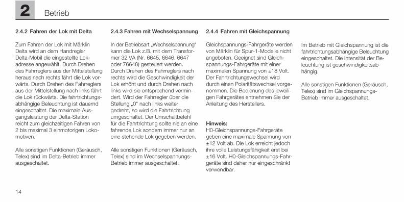
2.4.2 Fahren der Lok mit Delta
Zum Fahren der Lok mit MärklinDelta wird an dem Handregler Delta-Mobil die eingestellte Lok-adresse angewählt. Durch Drehendes Fahrreglers aus der Mittelstellungheraus nach rechts fährt die Lok vor-wärts. Durch Drehen des Fahrreglersaus der Mittelstellung nach links fährtdie Lok rückwärts. Die fahrtrichtungs-abhängige Beleuchtung ist dauerndeingeschaltet. Die maximale Aus-gangsleistung der Delta-Stationreicht zum gleichzeitigen Fahren von2 bis maximal 3 einmotorigen Loko-motiven.
Alle sonstigen Funktionen (Geräusch,Telex) sind im Delta-Betrieb immerausgeschaltet.
2.4.3 Fahren mit Wechselspannung
In der Betriebsart „Wechselspannung“kann die Lok z.B. mit dem Transfor-mer 32 VA (Nr. 6645, 6646, 6647oder 76648) gesteuert werden.Durch Drehen des Fahrreglers nachrechts wird die Geschwindigkeit derLok erhöht und durch Drehen nachlinks wird sie entsprechend vermin-dert. Wird der Fahrregler über dieStellung „0“ nach links weitergedreht, so wird die Fahrtrichtungumgeschaltet. Der Umschaltbefehlfür die Fahrtrichtung sollte nie an einefahrende Lok sondern immer nur aneine stehende Lok gegeben werden.
Alle sonstigen Funktionen (Geräusch,Telex) sind im Wechselspannungs-Betrieb immer ausgeschaltet.
2.4.4 Fahren mit Gleichspannung
Gleichspannungs-Fahrgeräte werdenvon Märklin für Spur-1-Modelle nichtangeboten. Geeignet sind Gleich-spannungs-Fahrgeräte mit einermaximalen Spannung von ±18 Volt.Der Fahrtrichtungswechsel wirddurch einen Polaritätswechsel vorge-nommen. Die Bedienung des jeweili-gen Fahrgerätes entnehmen Sie derAnleitung des Herstellers.
Hinweis: H0-Gleichspannungs-Fahrgerätegeben eine maximale Spannung von±12 Volt ab. Die Lok erreicht jedochihre volle Leistungsfähigkeit erst bei±16 Volt. H0-Gleichspannungs-Fahr-geräte sind daher nur eingeschränktverwendbar.
Im Betrieb mit Gleichspannung ist diefahrtrichtungsabhängige Beleuchtungeingeschaltet. Die Intensität der Be-leuchtung ist geschwindigkeitsab-hängig.
Alle sonstigen Funktionen (Geräusch,Telex) sind im Gleichspannungs-Betrieb immer ausgeschaltet.
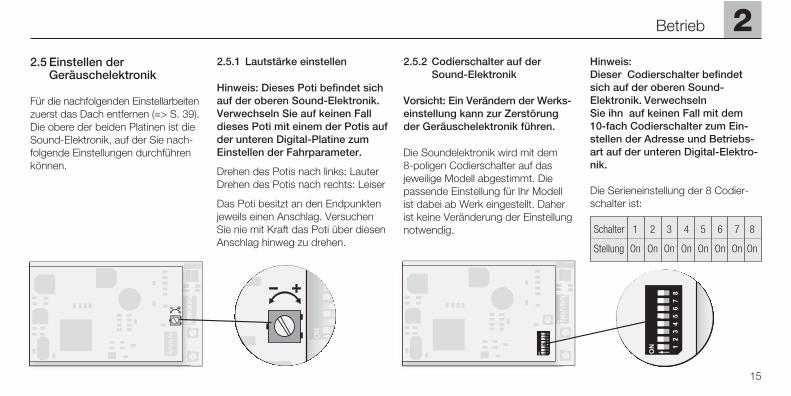
2.5 Einstellen der Geräuschelektronik
Für die nachfolgenden Einstellarbeitenzuerst das Dach entfernen (=> S. 39).Die obere der beiden Platinen ist dieSound-Elektronik, auf der Sie nach-folgende Einstellungen durchführenkönnen.
2.5.1 Lautstärke einstellen
Hinweis: Dieses Poti befindet sichauf der oberen Sound-Elektronik.Verwechseln Sie auf keinen Fall dieses Poti mit einem der Potis aufder unteren Digital-Platine zumEinstellen der Fahrparameter.
Drehen des Potis nach links: LauterDrehen des Potis nach rechts: Leiser
Das Poti besitzt an den Endpunktenjeweils einen Anschlag. VersuchenSie nie mit Kraft das Poti über diesenAnschlag hinweg zu drehen.
2.5.2 Codierschalter auf der Sound-Elektronik
Vorsicht: Ein Verändern der Werks-einstellung kann zur Zerstörungder Geräuschelektronik führen.
Die Soundelektronik wird mit dem 8-poligen Codierschalter auf dasjeweilige Modell abgestimmt. Diepassende Einstellung für Ihr Modellist dabei ab Werk eingestellt. Daherist keine Veränderung der Einstellungnotwendig.
Hinweis: Dieser Codierschalter befindetsich auf der oberen Sound-Elektronik. Verwechseln Sie ihn auf keinen Fall mit dem10-fach Codierschalter zum Ein-stellen der Adresse und Betriebs-art auf der unteren Digital-Elektro-nik.
Die Serieneinstellung der 8 Codier-schalter ist:
Schalter 1 2 3 4 5 6 7 8
Stellung On On On On On On On On
2
15
Betrieb
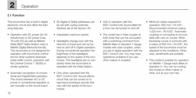
2.1 Function
This locomotive has a built-in digitalelectronic circuit and offers the follo-wing features:
• Operation with AC power (32 VAtransformer) or DC power (max.18 volts DC) as well as MärklinDelta (6607 Delta-Station only) orMärklin Digital (Motorola format).This locomotive is not designed foroperation with locomotive control-lers for other systems (example:pulse width control, operation withthe Central-Control 1 (6030) orsimilar systems).
• Automatic recognition of conven-tional and Digital/Delta operation.The choice between AC or DCpower in conventional operation isset manually on the circuit board.
• 80 Digital (4 Delta) addresses canbe set with coding switches.Address set at the factory: 44.
• Adjustable maximum speed.
• Headlights change over with thedirection of travel and can be tur-ned on and off in Digital operation.During conventional operation thebrightness of the headlightsdepends on the speed of the loco-motive. The headlights are on con-stantly when the locomotive isoperated with the Delta Station.
• Only when operated with the 6021 Control-Unit: Sound effectscircuit that can be turned on toreproduce prototype sounds thatvary with the speed of the loco-motive.
• Only in operation with the 6021 Control-Unit: Sound effect fora horn can be turned on and off.
• The model has a Telex coupler atboth ends that can be uncoupledwith a switching command fromMärklin Maxi or standard 1 Gaugemodels with claw couplers, whenyou are in digital operation with the6021 Control Unit. You may haveoperations problems if you useother makes of couplers.
• Minimum radius required for operation: 600 mm / 23-5/8”.Recommended minimum radius:1,020 mm / 40-5/32”. Automaticcoupling or uncoupling is not pos-sible with cars on curves. Whentraversing curves or turnouts witha radius of 600 mm / 23-5/8”, thespeed of the locomotive must beadjusted to the conditions. Other-wise, derailments are possible.
• This model is suitable for operationon Märklin 1 Gauge track (Maxi orstandard 1). You can try runningthis model on other makes oftrack, but at your own risk.
16
2 Operation
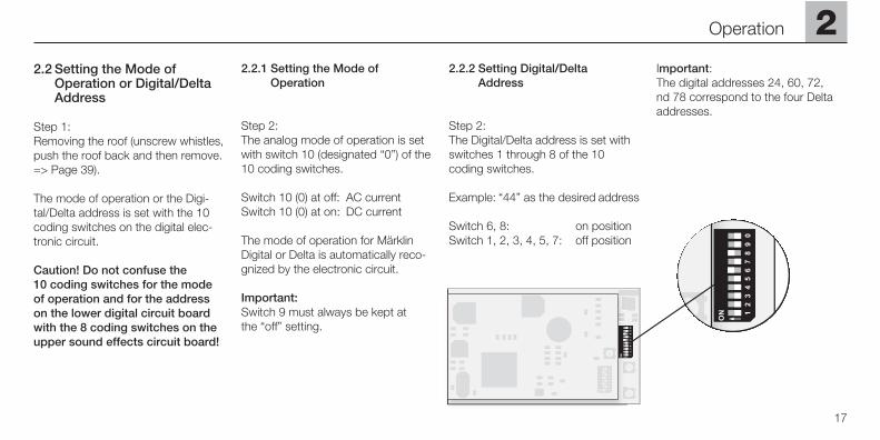
2.2 Setting the Mode of Operation or Digital/Delta Address
Step 1:Removing the roof (unscrew whistles,push the roof back and then remove.=> Page 39).
The mode of operation or the Digi-tal/Delta address is set with the 10coding switches on the digital elec-tronic circuit.
Caution! Do not confuse the 10 coding switches for the modeof operation and for the addresson the lower digital circuit boardwith the 8 coding switches on theupper sound effects circuit board!
2.2.1 Setting the Mode of Operation
Step 2:The analog mode of operation is setwith switch 10 (designated “0”) of the10 coding switches.
Switch 10 (0) at off: AC currentSwitch 10 (0) at on: DC current
The mode of operation for MärklinDigital or Delta is automatically reco-gnized by the electronic circuit.
Important:Switch 9 must always be kept at the “off” setting.
2.2.2 Setting Digital/Delta Address
Step 2:The Digital/Delta address is set withswitches 1 through 8 of the 10coding switches.
Example: “44” as the desired address
Switch 6, 8: on positionSwitch 1, 2, 3, 4, 5, 7: off position
Important: The digital addresses 24, 60, 72, nd 78 correspond to the four Deltaaddresses.
2
17
Operation
18
2 Operation
~
9 0 =
9 0
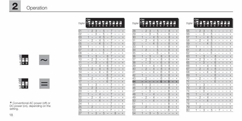
* Conventional AC power (off) or DC power (on), depending on the setting.
Digital Digital Digital
28 – 2 3 – 5 – – 8 – *29 – – 3 – 5 – – 8 – *30 1 – – 4 5 – – 8 – *31 – 2 – 4 5 – – 8 – *32 – – – 4 5 – – 8 – *33 1 – – – 5 – – 8 – *34 – 2 – – 5 – – 8 – *35 – – – – 5 – – 8 – *36 1 – 3 – – 6 – 8 – *37 – 2 3 – – 6 – 8 – *38 – – 3 – – 6 – 8 – *39 1 – – 4 – 6 – 8 – *40 – 2 – 4 – 6 – 8 – *41 – – – 4 – 6 – 8 – *42 1 – – – – 6 – 8 – *43 – 2 – – – 6 – 8 – *44 – – – – – 6 – 8 – *45 1 – 3 – – – – 8 – *46 – 2 3 – – – – 8 – *47 – – 3 – – – – 8 – *48 1 – – 4 – – – 8 – *49 – 2 – 4 – – – 8 – *50 – – – 4 – – – 8 – *51 1 – – – – – – 8 – *52 – 2 – – – – – 8 – *53 – – – – – – – 8 – *54 1 – 3 – 5 – – – – *
55 – 2 3 – 5 – – – – *56 – – 3 – 5 – – – – *57 1 – – 4 5 – – – – *58 – 2 – 4 5 – – – – *59 – – – 4 5 – – – – *60 1 – – – 5 – – – – *61 – 2 – – 5 – – – – *62 – – – – 5 – – – – *63 1 – 3 – – 6 – – – *64 – 2 3 – – 6 – – – *65 – – 3 – – 6 – – – *66 1 – – 4 – 6 – – – *67 – 2 – 4 – 6 – – – *68 – – – 4 – 6 – – – *69 1 – – – – 6 – – – *70 – 2 – – – 6 – – – *71 – – – – – 6 – – – *72 1 – 3 – – – – – – *73 – 2 3 – – – – – – *74 – – 3 – – – – – – *75 1 – – 4 – – – – – *76 – 2 – 4 – – – – – *77 – – – 4 – – – – – *78 1 – – – – – – – – *79 – 2 – – – – – – – *80 1 – 3 – 5 – 7 – – *
01 – 2 3 – 5 – 7 – – *02 – – 3 – 5 – 7 – – *03 1 – – 4 5 – 7 – – *04 – 2 – 4 5 – 7 – – *05 – – – 4 5 – 7 – – *06 1 – – – 5 – 7 – – *07 – 2 – – 5 – 7 – – *08 – – – – 5 – 7 – – *09 1 – 3 – – 6 7 – – *10 – 2 3 – – 6 7 – – *11 – – 3 – – 6 7 – – *12 1 – – 4 – 6 7 – – *13 – 2 – 4 – 6 7 – – *14 – – – 4 – 6 7 – – *15 1 – – – – 6 7 – – *16 – 2 – – – 6 7 – – *17 – – – – – 6 7 – – *18 1 – 3 – – – 7 – – *19 – 2 3 – – – 7 – – *20 – – 3 – – – 7 – – *21 1 – – 4 – – 7 – – *22 – 2 – 4 – – 7 – – *23 – – – 4 – – 7 – – *24 1 – – – – – 7 – – *25 – 2 – – – – 7 – – *26 – – – – – – 7 – – *27 1 – 3 – 5 – – 8 – *
2
19
Operation
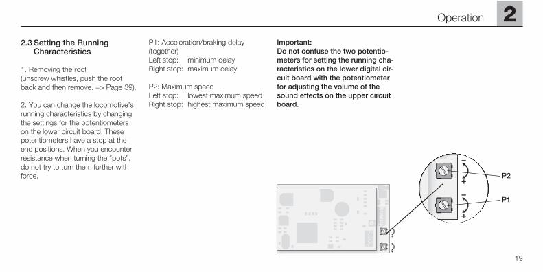
2.3 Setting the Running Characteristics
1. Removing the roof (unscrew whistles, push the roofback and then remove. => Page 39).
2. You can change the locomotive’srunning characteristics by changingthe settings for the potentiometerson the lower circuit board. Thesepotentiometers have a stop at theend positions. When you encounterresistance when turning the “pots”,do not try to turn them further withforce.
P1: Acceleration/braking delay(together)Left stop: minimum delayRight stop: maximum delay
P2: Maximum speedLeft stop: lowest maximum speed Right stop: highest maximum speed
Important: Do not confuse the two potentio-meters for setting the running cha-racteristics on the lower digital cir-cuit board with the potentiometerfor adjusting the volume of thesound effects on the upper circuitboard.
P2
P1
2.4 Operation with the Different Power Systems
2.4.1 Digital
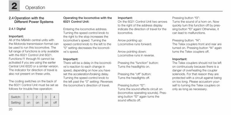
Important:All of the Märklin central units withthe Motorola transmission format canbe used to run this locomotive. Thefull range of functions is only availablewith the 6021 Control Unit 6021.Functions f1 through f4 cannot beactivated if you are using the earlierCentral Unit 6020 or a similar version.The indicator for direction of travel isalso not present on these units.
The coding switches on the back ofthe 6021 Control Unit must be set asfollows for trouble free operation:
Switch: 1 2 3 4
Setting: on on on off
Operating the locomotive with the6021 Control Unit:
Entering the locomotive address.Turning the speed control knob tothe right to the stop increases thelocomotive’s speed. Turning thespeed control knob to the left to the"0” setting decreases the locomoti-ve’s speed.
Important: There will be a delay in the locomoti-ve’s reaction to each change inspeed, depending on how you haveset the acceleration/braking delay.Turning the speed control knob tothe left past the “0” setting: Reversesthe locomotive’s direction of travel.
Important: On the 6021 Control Unit two arrowsto the right of the address displayindicate the direction of travel for thelocomotive.
Arrow pointing up: Locomotive runs forward.
Arrow pointing down: Locomotive runs in reverse.
Pressing the “function” button: Turns the headlights on.
Pressing the “off” button: Turns the headlights off.
Pressing button “f2”: Turns the sound effects circuit on(locomotive operating sounds). Pres-sing button “f2” again turns thesound effects off.
Pressing button “f3”: Turns the sound of a horn on. Nowquickly turn this function off by pres-sing button “f3” again! Otherwise, itcan lead to malfunctions.
Pressing button: “f4”:The Telex couplers front and rear areturned on. Pressing button “f4” againturns the Telex couplers off.
Important:The Telex couplers should not be lefton continuously because there is adanger of overheating the couplersolenoids. For that reason they areprotected with a circuit against beingon too long. Please accustom your-self to turning the Telex couplers ononly as long as necessary.
20
2 Operation
2
21
Operation
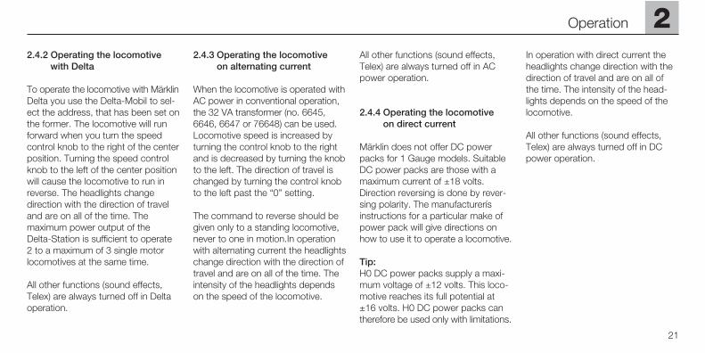
2.4.2 Operating the locomotivewith Delta
To operate the locomotive with MärklinDelta you use the Delta-Mobil to sel-ect the address, that has been set onthe former. The locomotive will runforward when you turn the speedcontrol knob to the right of the centerposition. Turning the speed controlknob to the left of the center positionwill cause the locomotive to run inreverse. The headlights changedirection with the direction of traveland are on all of the time. The maximum power output of the Delta-Station is sufficient to operate2 to a maximum of 3 single motorlocomotives at the same time.
All other functions (sound effects,Telex) are always turned off in Deltaoperation.
2.4.3 Operating the locomotive on alternating current
When the locomotive is operated withAC power in conventional operation,the 32 VA transformer (no. 6645,6646, 6647 or 76648) can be used.Locomotive speed is increased byturning the control knob to the rightand is decreased by turning the knobto the left. The direction of travel ischanged by turning the control knobto the left past the “0” setting.
The command to reverse should begiven only to a standing locomotive,never to one in motion.In operationwith alternating current the headlightschange direction with the direction oftravel and are on all of the time. Theintensity of the headlights dependson the speed of the locomotive.
All other functions (sound effects,Telex) are always turned off in ACpower operation.
2.4.4 Operating the locomotive on direct current
Märklin does not offer DC powerpacks for 1 Gauge models. SuitableDC power packs are those with amaximum current of ±18 volts.Direction reversing is done by rever-sing polarity. The manufacturerísinstructions for a particular make ofpower pack will give directions onhow to use it to operate a locomotive.
Tip:H0 DC power packs supply a maxi-mum voltage of ±12 volts. This loco-motive reaches its full potential at±16 volts. H0 DC power packs cantherefore be used only with limitations.
In operation with direct current theheadlights change direction with thedirection of travel and are on all ofthe time. The intensity of the head-lights depends on the speed of thelocomotive.
All other functions (sound effects,Telex) are always turned off in DCpower operation.
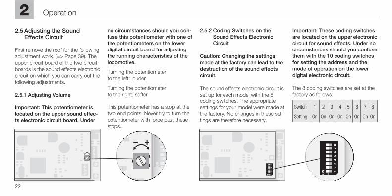
2.5 Adjusting the Sound Effects Circuit
First remove the roof for the followingadjustment work. (=> Page 39). Theupper circuit board of the two circuitboards is the sound effects electroniccircuit on which you can carry out thefollowing adjustments.
2.5.1 Adjusting Volume
Important: This potentiometer islocated on the upper sound effec-ts electronic circuit board. Under
no circumstances should you con-fuse this potentiometer with one ofthe potentiometers on the lowerdigital circuit board for adjustingthe running characteristics of thelocomotive.
Turning the potentiometer to the left: louder
Turning the potentiometer to the right: softer
This potentiometer has a stop at thetwo end points. Never try to turn thepotentiometer with force past thesestops.
2.5.2 Coding Switches on the Sound Effects Electronic Circuit
Caution: Changing the settingsmade at the factory can lead to thedestruction of the sound effectscircuit.
The sound effects electronic circuit isset up for each model with the 8coding switches. The appropriatesettings for your model were made atthe factory. No changes in these set-tings are therefore necessary.
Important: These coding switchesare located on the upper electroniccircuit for sound effects. Under nocircumstances should you confusethem with the 10 coding switchesfor setting the address and themode of operation on the lowerdigital electronic circuit.
The 8 coding switches are set at thefactory as follows:
Switch 1 2 3 4 5 6 7 8
Setting On On On On On On On On
22
2 Operation
2
23
Fonctionnement
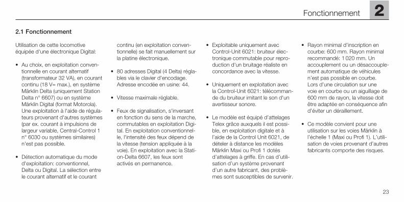
2.1 Fonctionnement
Utilisation de cette locomotiveéquipée d'une électronique Digital:
• Au choix, en exploitation conven-tionnelle en courant alternatif(transformateur 32 VA), en courantcontinu (18 V= max.), en systèmeMärklin Delta (uniquement StationDelta n° 6607) ou en systèmeMärklin Digital (format Motorola).Une exploitation à l'aide de régula-teurs provenant d'autres systèmes(par ex. courant à impulsions delargeur variable, Central-Control 1n° 6030 ou systèmes similaires)n'est pas possible.
• Détection automatique du moded'exploitation: conventionnel,Delta ou Digital. La sélection entrele courant alternatif et le courant
continu (en exploitation conven-tionnelle) se fait manuellement surla platine électronique.
• 80 adresses Digital (4 Delta) régla-bles via le clavier d'encodage.Adresse encodée en usine: 44.
• Vitesse maximale réglable.
• Feux de signalisation, s'inversanten fonction du sens de la marche,commutables en exploitation Digi-tal. En exploitation conventionnel-le, l'intensité des feux dépend dela vitesse (tension appliquée à lavoie). En exploitation avec la Stati-on-Delta 6607, les feux sontactivés en permanence.
• Exploitable uniquement avec Control-Unit 6021: bruiteur élec-tronique commutable pour repro-duction d'un bruitage réaliste enconcordance avec la vitesse.
• Uniquement en exploitation avecla Control-Unit 6021: télécomman-de du bruiteur imitant le son d'unavertisseur sonore.
• Le modèle est équipé d’attelagesTelex grâce auxquels il est possi-ble, en exploitation digitale et àl’aide de la Control Unit 6021, dedételer à distance les modèlesMärklin Maxi ou Profi 1 dotésd’attelages à griffe. En cas d’utili-sation d’un système provenantd’un autre fabricant, des problè-mes sont susceptibles de survenir.
• Rayon minimal d’inscription encourbe: 600 mm. Rayon minimalrecommandé: 1 020 mm. Unaccouplement ou un désaccouple-ment automatique de véhiculesn’est pas possible en courbe. Lors d’une circulation sur une voie en courbe ou un aiguillage de600 mm de rayon, la vitesse doitêtre adaptée en conséquence afind’éviter un déraillement.
• Ce modèle convient pour une utilisation sur les voies Märklin àl’échelle 1 (Maxi ou Profi 1). L’utili-sation de voies provenant d’autresfabricants comporte des risques.
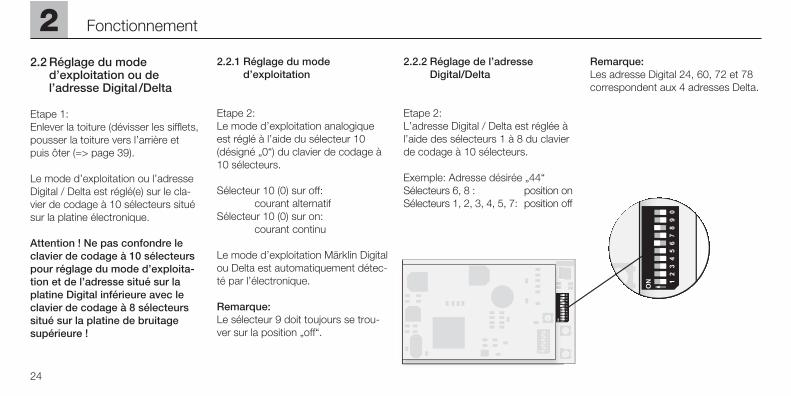
2.2 Réglage du mode d’exploitation ou de l’adresse Digital /Delta
Etape 1: Enlever la toiture (dévisser les sifflets,pousser la toiture vers l’arrière et puis ôter (=> page 39).
Le mode d’exploitation ou l’adresseDigital / Delta est réglé(e) sur le cla-vier de codage à 10 sélecteurs situésur la platine électronique.
Attention ! Ne pas confondre leclavier de codage à 10 sélecteurspour réglage du mode d’exploita-tion et de l’adresse situé sur laplatine Digital inférieure avec leclavier de codage à 8 sélecteurssitué sur la platine de bruitagesupérieure !
2.2.1 Réglage du mode d’exploitation
Etape 2:Le mode d’exploitation analogiqueest réglé à l’aide du sélecteur 10(désigné „0“) du clavier de codage à10 sélecteurs.
Sélecteur 10 (0) sur off: courant alternatif
Sélecteur 10 (0) sur on:courant continu
Le mode d’exploitation Märklin Digitalou Delta est automatiquement détec-té par l’électronique.
Remarque: Le sélecteur 9 doit toujours se trou-ver sur la position „off“.
2.2.2 Réglage de l’adresse Digital/Delta
Etape 2:L’adresse Digital / Delta est réglée àl’aide des sélecteurs 1 à 8 du clavierde codage à 10 sélecteurs.
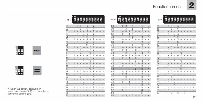
Exemple: Adresse désirée „44“Sélecteurs 6, 8 : position onSélecteurs 1, 2, 3, 4, 5, 7: position off
Remarque: Les adresse Digital 24, 60, 72 et 78correspondent aux 4 adresses Delta.
24
2 Fonctionnement
2
25
Fonctionnement
~
9 0 =
9 0
* Selon la position, courant con-ventionnel alternatif (off) ou courant con-ventionnel continu (on).
Digital Digital Digital
28 – 2 3 – 5 – – 8 – *29 – – 3 – 5 – – 8 – *30 1 – – 4 5 – – 8 – *31 – 2 – 4 5 – – 8 – *32 – – – 4 5 – – 8 – *33 1 – – – 5 – – 8 – *34 – 2 – – 5 – – 8 – *35 – – – – 5 – – 8 – *36 1 – 3 – – 6 – 8 – *37 – 2 3 – – 6 – 8 – *38 – – 3 – – 6 – 8 – *39 1 – – 4 – 6 – 8 – *40 – 2 – 4 – 6 – 8 – *41 – – – 4 – 6 – 8 – *42 1 – – – – 6 – 8 – *43 – 2 – – – 6 – 8 – *44 – – – – – 6 – 8 – *45 1 – 3 – – – – 8 – *46 – 2 3 – – – – 8 – *47 – – 3 – – – – 8 – *48 1 – – 4 – – – 8 – *49 – 2 – 4 – – – 8 – *50 – – – 4 – – – 8 – *51 1 – – – – – – 8 – *52 – 2 – – – – – 8 – *53 – – – – – – – 8 – *54 1 – 3 – 5 – – – – *
55 – 2 3 – 5 – – – – *56 – – 3 – 5 – – – – *57 1 – – 4 5 – – – – *58 – 2 – 4 5 – – – – *59 – – – 4 5 – – – – *60 1 – – – 5 – – – – *61 – 2 – – 5 – – – – *62 – – – – 5 – – – – *63 1 – 3 – – 6 – – – *64 – 2 3 – – 6 – – – *65 – – 3 – – 6 – – – *66 1 – – 4 – 6 – – – *67 – 2 – 4 – 6 – – – *68 – – – 4 – 6 – – – *69 1 – – – – 6 – – – *70 – 2 – – – 6 – – – *71 – – – – – 6 – – – *72 1 – 3 – – – – – – *73 – 2 3 – – – – – – *74 – – 3 – – – – – – *75 1 – – 4 – – – – – *76 – 2 – 4 – – – – – *77 – – – 4 – – – – – *78 1 – – – – – – – – *79 – 2 – – – – – – – *80 1 – 3 – 5 – 7 – – *
01 – 2 3 – 5 – 7 – – *02 – – 3 – 5 – 7 – – *03 1 – – 4 5 – 7 – – *04 – 2 – 4 5 – 7 – – *05 – – – 4 5 – 7 – – *06 1 – – – 5 – 7 – – *07 – 2 – – 5 – 7 – – *08 – – – – 5 – 7 – – *09 1 – 3 – – 6 7 – – *10 – 2 3 – – 6 7 – – *11 – – 3 – – 6 7 – – *12 1 – – 4 – 6 7 – – *13 – 2 – 4 – 6 7 – – *14 – – – 4 – 6 7 – – *15 1 – – – – 6 7 – – *16 – 2 – – – 6 7 – – *17 – – – – – 6 7 – – *18 1 – 3 – – – 7 – – *19 – 2 3 – – – 7 – – *20 – – 3 – – – 7 – – *21 1 – – 4 – – 7 – – *22 – 2 – 4 – – 7 – – *23 – – – 4 – – 7 – – *24 1 – – – – – 7 – – *25 – 2 – – – – 7 – – *26 – – – – – – 7 – – *27 1 – 3 – 5 – – 8 – *
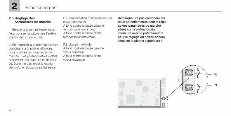
2.3 Réglage des paramètres de marche
1. Enlever la toiture (dévisser les sif-flets, pousser la toiture vers l’arrièreet puis ôter => page. 39).
2. En modifiant la position des poten-tiomètres sur la platine inférieure,vous modifiez les paramètres demarche. Les potentiomètres rotatifspossèdent une butée en fin de cour-se. Donc, ne pas forcer la rotationdès qu'une résistance se fait sentir.
P1: temporisation d'accélération-frei-nage (commune).A fond contre la butée gauche: temporisation minimale. A fond contre la butée droite: temporisation maximale.
P2: vitesse maximale.A fond contre la butée gauche: valeur minimale.A fond contre la butée droite: valeur maximale.
Remarque: Ne pas confondre lesdeux potentiomètres pour le régla-ge des paramètres de marchesitués sur la platine Digitalinférieure avec le potentiomètrepour le réglage du niveau sonoresitué sur la platine supérieure !
26
2 Fonctionnement
P2
P1
2.4 Exploitation avec dessystèmes d'alimentation séparés
2.4.1 Digital
Remarque: Toutes les unités centrales Märklinfonctionnant avec le format de don-nées Motorola peuvent être utiliséespour l'exploitation des trains. Cepen-dant, la totalité des fonctions n'estdisponible qu'avec la Control Unit6021. En cas d'utilisation de l'ancien-ne Central Unit 6020 ou d'une versi-on similaire, les fonctions f1 à f4 nepeuvent pas être commutées. Enoutre, l'indication de sens de marchene fonctionne pas.
Pour une exploitation impeccableavec la Control Unit 6021, le clavier d'encodage situé sur la face arrière de l'appareil doit être réglé commesuit:
Sélecteur: 1 2 3 4
Position: on on on off
Exploitation avec la Control Unit 6021:
Introduire l'adresse de locomotive.Tourner le bouton de réglage devitesse vers la droite jusqu'à la butéeaugmente la vitesse de la locomotive.Tourner le bouton de réglage devitesse vers la gauche jusqu'à laposition „0“ diminue la vitesse de lalocomotive.
Remarque:la locomotive réagit avec un tempsde réponse conforme au réglage dela temporisation d'accélération-frei-nage encodée. Tourner le bouton deréglage en passant outre la position„0“ change le sens de marche.
Remarque: sur la Control Unit 6021, le sens demarche est indiqué par les deuxflèches situées à droite de l'indica-teur d'adresse.
Flèche vers le haut: le locomotive roule en avant.
Flèche vers le bas: le locomotive roule en arrière.
Presser la touche „function“: activation des feux de signalisation.
Presser la touche „off“: désactivationdes feux de signalisation.
Une pression sur la touche „f2“ :Activation du bruitage (de marche).Une autre pression sur la touche „f2“désactive le bruitage.
Une pression sur la touche „f3“ :Activation du bruitage de l’avertisseursonore suivie ensuite impérativementd’une autre pression sur la touche„f3“ pour désactiver le bruitage souspeine de provoquer un dysfonc-tionnement!
Pression sur la touche „f4“ :Attelages Telex avant et arrièreactivés. Une seconde pression sur la touche „f4“ désactive les attelagesTelex.
Remarque importante: Les attelages Telex ne peuvent êtreactivés en permanence (échauffe-ment du bobinage). La locomotiveest par conséquent équipée d'unesécurité en cas de pression trop longue sur la touche de commande.Il faut donc que l'opérateur s'habitueà ne presser la touche que pendantle temps nécessaire au dételage.
2
27
Fonctionnement
2.4.2 Conduite de la locomotive en mode Delta
L'adresse qui a été réglée pour lalocomotive est choisie sur le régula-teur manuel Delta-Mobil pour per-mettre à la locomotive de fonctionneren Märklin Delta. Si l’on actionne lerégulateur de conduite de la positioncentrale vers la droite, la locomotivese déplace en marche avant. Si l'onactionne le régulateur de conduite dela position centrale vers la gauche, lalocomotive se déplace en marchearrière. L'éclairage en fonction dusens de la marche est constammentenclenché. La puissance de sortiemaximum de la Delta-Station est suf-fisante pour une exploitation simul-tanée de 2 à 3 locomotives à un seulmoteur.
Toutes les autres fonctions (bruitage,Telex) sont toujours désactivées enexploitation Delta.
2.4.3 Conduite en tension alternative
Dans le mode d'exploitation „courantalternatif“, la locomotive peut êtrepilotée par exemple avec le transfor-mateur de 32 VA (n° 6645, 6646,6647 ou 76648). En tournant le régu-lateur de vitesse vers la droite, lavitesse de la locomotive est aug-mentée, en le tournant vers la gau-che elle est réduite en conséquence.Si le régulateur est tourné au-delà dela position «0» vers la gauche, le sensde la marche est inversé. La com-mande d'inversion du sens de lamarche ne devrait jamais être trans-mise à une locomotive en circulation,mais toujours à une locomotive setrouvant à l‘ arrêt.
Toutes les autres fonctions (bruitage,Telex) sont toujours désactivées enexploitation à courant alternatif.
2.4.4 Conduite en tension continue
Les règulateurs de vitesse à tensioncontinue ne sont pas proposés parMärklin pour les modèles de Voie 1. Les régulateurs de vitesse à tensioncontinue ayant une tension maximalede ±18 volt sont adaptés. Le chan-gement du sens de la marche estréalisé grâce à un changement depolarité. Vous trouverez les instruc-tions de commande relatives aux dif-férents régulateurs de vitesse dans lanotice du fabricant.
Indication: Les régulateurs de vitesse H0 à ten-sion continue fournissent une tensionmaximum de ±12 volt. La locomotiven'atteint cependant sa pleine capa-cité qu'avec ±16 volt. Les régulateursde vitesse H0 à tension continue nepeuvent donc être utilisés qu'aveccertaines restrictions.L'éclairage en fonction du sens de lamarche est enclenché en exploitationsous tension continue. L'intensité deléclairage dépend de la vitesse.
Toutes les autres fonctions (bruitage,Telex) sont toujours désactivées enexploitation à courant continu.
28
2 Fonctionnement
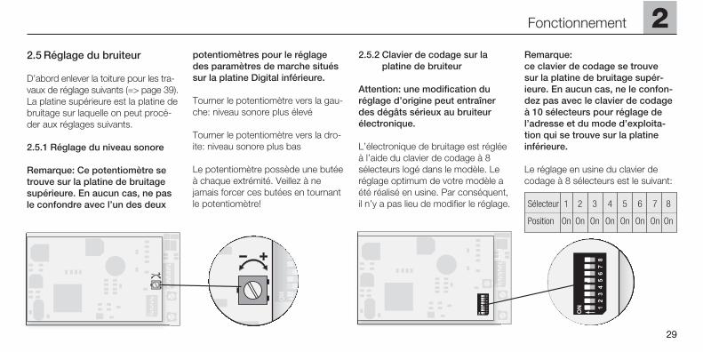
2.5 Réglage du bruiteur
D’abord enlever la toiture pour les tra-vaux de réglage suivants (=> page 39).La platine supérieure est la platine debruitage sur laquelle on peut procé-der aux réglages suivants.
2.5.1 Réglage du niveau sonore
Remarque: Ce potentiomètre setrouve sur la platine de bruitagesupérieure. En aucun cas, ne pasle confondre avec l’un des deux
potentiomètres pour le réglagedes paramètres de marche situéssur la platine Digital inférieure.
Tourner le potentiomètre vers la gau-che: niveau sonore plus élevé
Tourner le potentiomètre vers la dro-ite: niveau sonore plus bas
Le potentiomètre possède une butéeà chaque extrémité. Veillez à nejamais forcer ces butées en tournantle potentiomètre!
2.5.2 Clavier de codage sur la platine de bruiteur
Attention: une modification duréglage d’origine peut entraînerdes dégâts sérieux au bruiteurélectronique.
L’électronique de bruitage est régléeà l’aide du clavier de codage à 8sélecteurs logé dans le modèle. Leréglage optimum de votre modèle aété réalisé en usine. Par conséquent,il n’y a pas lieu de modifier le réglage.
Remarque: ce clavier de codage se trouve sur la platine de bruitage supér-ieure. En aucun cas, ne le confon-dez pas avec le clavier de codageà 10 sélecteurs pour réglage del’adresse et du mode d’exploita-tion qui se trouve sur la platineinférieure.
Le réglage en usine du clavier decodage à 8 sélecteurs est le suivant:
Sélecteur 1 2 3 4 5 6 7 8
Position On On On On On On On On
2
29
Fonctionnement
29
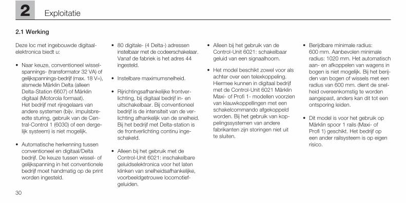
2.1 Werking
Deze loc met ingebouwde digitaal-elektronica biedt u:
• Naar keuze, conventioneel wissel-spannings- (transformator 32 VA) ofgelijkspannings-bedrijf (max. 18 V=),alsmede Märklin Delta (alleenDelta-Station 6607) of Märklin digitaal (Motorola formaat). Het bedrijf met rijregelaars vanandere systemen (bijv. impulsbre-edte sturing, gebruik van de Cen-tral-Control 1 (6030) of een derge-lijk systeem) is niet mogelijk.
• Automatische herkenning tussenconventioneel en digitaal/Deltabedrijf. De keuze tussen wissel- ofgelijkspanning in het conventionelebedrijf moet handmatig op de printworden ingesteld.
• 80 digitale- (4 Delta-) adresseninstelbaar met de codeerschakelaar.Vanaf de fabriek is het adres 44ingesteld.
• Instelbare maximumsnelheid.
• Rijrichtingsafhankelijke frontver-lichting, bij digitaal bedrijf in- enuitschakelbaar. Bij conventioneelbedrijf is de intensiteit van de ver-lichting afhankelijk van de snelheid.Bij het bedrijf met Delta-station isde frontverlichting continu inge-schakeld.
• Alleen bij het gebruik met deControl-Unit 6021: inschakelbaregeluidselektronica voor het latenklinken van snelheidsafhankelijke,voorbeeldgetrouwe locomotief-geluiden.
• Alleen bij het gebruik van deControl-Unit 6021: schakelbaargeluid van een signaalhoorn.
• Het model beschikt zowel voor alsachter over een telexkoppeling.Hiermee kunnen in digitaal bedrijfmet de Control-Unit 6021 MärklinMaxi- of Profi 1- modellen voorzienvan klauwkoppellingen met eenschakelcommando afgekoppeldworden. Bij het gebruik van kop-pelingssystemen van andere fabrikanten zijn storingen niet uit te sluiten.
• Berijdbare minimale radius: 600 mm. Aanbevolen minimaleradius: 1020 mm. Het automatischaan- en afkoppelen van wagens inbogen is niet mogelijk. Bij het berij-den van bogen of wissels met eenradius van 600 mm. dient de snel-heid overeenkomstig te wordenaangepast, anders kan dit tot eenontsporing leiden.
• Dit model is voor het gebruik opMärklin spoor 1 rails (Maxi- of Profi 1) geschikt. Het bedrijf opeen ander railsysteem is op eigenrisico.
30
2 Exploitatie
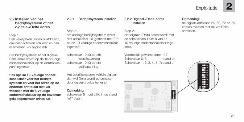
2.2 Instellen van het bedrijfssysteem of het digitale-/Delta adres.
Stap 1: Dak verwijderen (fluiten er afdraaien,dak naar achteren schuiven en daner afnemen. => pagina 39).
Het bedrijfssysteem of het digitale-Delta adres wordt op de 10-voudigecodeerschakelaar op de elektronica-print ingesteld.
Pas op! De 10-voudige codeer-schakelaar voor het bedrijfs-systeem en voor het adres op deonderste printplaat niet ver-wisselen met de 8-voudigecodeerschakelaar op de bovenstegeluidsgenerator printplaat.
2.2.1 Bedrijfssysteem instellen
Stap 2: het analoge bedrijfssysteem wordtmet schakelaar 10 (gemerkt met “0“)op de 10-voudige codeerschakelaaringesteld.
schakelaar 10 (0) op off: wisselspanning
schakelaar 10 (0) op on: gelijkspanning
Het bedrijfssysteem Märklin digitaal,dan wel Delta wordt automatischdoor de elektronica herkend.
Opmerking: schakelaar 9 moet altijd in de stand“off” staan.
2.2.2 Digitaal-/Delta-adres instellen
Stap 2:Het digitale-/Delta adres wordt metde schakelaars 1 t/m 8 van de 10-voudige codeerschakelaar inge-steld.
Voorbeeld: gewenst adres “44“ Schakelaar 6, 8: stand onSchakelaar 1, 2, 3, 4, 5, 7: stand of
Opmerking: de digitale adressen 24, 60, 72 en 78komen overeen met de vier Deltaadressen.
2
31
Exploitatie
32
2 Exploitatie
~
9 0 =
9 0
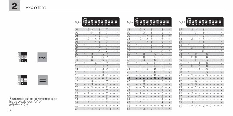
* afhankelijk van de conventionele instel-ling op wisselstroom (off) of gelijkstroom (on).
Digital Digital Digital
28 – 2 3 – 5 – – 8 – *29 – – 3 – 5 – – 8 – *30 1 – – 4 5 – – 8 – *31 – 2 – 4 5 – – 8 – *32 – – – 4 5 – – 8 – *33 1 – – – 5 – – 8 – *34 – 2 – – 5 – – 8 – *35 – – – – 5 – – 8 – *36 1 – 3 – – 6 – 8 – *37 – 2 3 – – 6 – 8 – *38 – – 3 – – 6 – 8 – *39 1 – – 4 – 6 – 8 – *40 – 2 – 4 – 6 – 8 – *41 – – – 4 – 6 – 8 – *42 1 – – – – 6 – 8 – *43 – 2 – – – 6 – 8 – *44 – – – – – 6 – 8 – *45 1 – 3 – – – – 8 – *46 – 2 3 – – – – 8 – *47 – – 3 – – – – 8 – *48 1 – – 4 – – – 8 – *49 – 2 – 4 – – – 8 – *50 – – – 4 – – – 8 – *51 1 – – – – – – 8 – *52 – 2 – – – – – 8 – *53 – – – – – – – 8 – *54 1 – 3 – 5 – – – – *
55 – 2 3 – 5 – – – – *56 – – 3 – 5 – – – – *57 1 – – 4 5 – – – – *58 – 2 – 4 5 – – – – *59 – – – 4 5 – – – – *60 1 – – – 5 – – – – *61 – 2 – – 5 – – – – *62 – – – – 5 – – – – *63 1 – 3 – – 6 – – – *64 – 2 3 – – 6 – – – *65 – – 3 – – 6 – – – *66 1 – – 4 – 6 – – – *67 – 2 – 4 – 6 – – – *68 – – – 4 – 6 – – – *69 1 – – – – 6 – – – *70 – 2 – – – 6 – – – *71 – – – – – 6 – – – *72 1 – 3 – – – – – – *73 – 2 3 – – – – – – *74 – – 3 – – – – – – *75 1 – – 4 – – – – – *76 – 2 – 4 – – – – – *77 – – – 4 – – – – – *78 1 – – – – – – – – *79 – 2 – – – – – – – *80 1 – 3 – 5 – 7 – – *
01 – 2 3 – 5 – 7 – – *02 – – 3 – 5 – 7 – – *03 1 – – 4 5 – 7 – – *04 – 2 – 4 5 – 7 – – *05 – – – 4 5 – 7 – – *06 1 – – – 5 – 7 – – *07 – 2 – – 5 – 7 – – *08 – – – – 5 – 7 – – *09 1 – 3 – – 6 7 – – *10 – 2 3 – – 6 7 – – *11 – – 3 – – 6 7 – – *12 1 – – 4 – 6 7 – – *13 – 2 – 4 – 6 7 – – *14 – – – 4 – 6 7 – – *15 1 – – – – 6 7 – – *16 – 2 – – – 6 7 – – *17 – – – – – 6 7 – – *18 1 – 3 – – – 7 – – *19 – 2 3 – – – 7 – – *20 – – 3 – – – 7 – – *21 1 – – 4 – – 7 – – *22 – 2 – 4 – – 7 – – *23 – – – 4 – – 7 – – *24 1 – – – – – 7 – – *25 – 2 – – – – 7 – – *26 – – – – – – 7 – – *27 1 – 3 – 5 – – 8 – *
2
33
Exploitatie
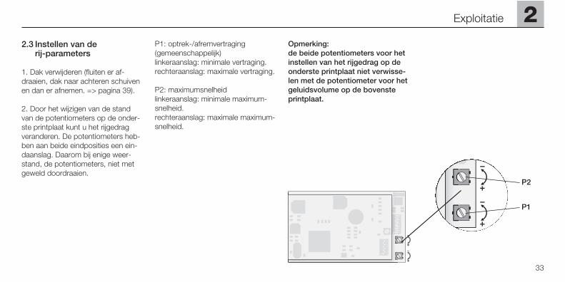
2.3 Instellen van de rij-parameters
1. Dak verwijderen (fluiten er af-draaien, dak naar achteren schuivenen dan er afnemen. => pagina 39).
2. Door het wijzigen van de standvan de potentiometers op de onder-ste printplaat kunt u het rijgedragveranderen. De potentiometers heb-ben aan beide eindposities een ein-daanslag. Daarom bij enige weer-stand, de potentiometers, niet metgeweld doordraaien.
P1: optrek-/afremvertraging(gemeenschappelijk)linkeraanslag: minimale vertraging.rechteraanslag: maximale vertraging.
P2: maximumsnelheidlinkeraanslag: minimale maximum-snelheid.rechteraanslag: maximale maximum-snelheid.
Opmerking: de beide potentiometers voor hetinstellen van het rijgedrag op deonderste printplaat niet verwisse-len met de potentiometer voor hetgeluidsvolume op de bovensteprintplaat.
P2
P1
2.4 Het bedrijf met de verschillende bedrijfssystemen
2.4.1 Digitaal
Opmerking:voor het rijden kunnen alle Märklincentrales met het Motorola-formaatgebruikt worden. Het benutten vanalle mogelijkheden is alleen met deControl Unit 6021 mogelijk. Bij hetgebruik van de oudere Central Unit6020 of een gelijkwaardige versiekunnen de functies f1 t/m f4 nietgeschakeld worden. Tevens ontbre-ekt de rijrichtingsweergave.
Om zonder problemen alle functiesaan te kunnen sturen, moeten de
schakelaars op de achterzijde van deControl Unit op de volgende wijzeingesteld worden:
Schakelaar: 1 2 3 4
Stand: on on on off
Rijden met de Control Unit 6021:
Loc adres invoeren.Door de regelknop naar rechts, totaan de aanslag, te draaien wordt desnelheid van de locomotief verhoogt.Het verdraaien van de regelknopnaar links, tot aan de stand „0” ver-minderd de snelheid van de loc.
Opmerking: afhankelijk van de ingestelde optrek-/afremvertraging, reageert de loc ver-traagd op de verdraaiing van deregelknop naar de nieuwe stand.
Het verdraaien van de regelknopnaar links, door de stand „0”: omkeren van de rijrichting.
Opmerking:de rijrichting wordt bij de Control Unit6021 via de rijrichtingspijlen, naasthet adres, weergegeven.
Pijl naar boven: loc rijdt vooruit.
Pijl naar beneden: loc rijdt achteruit.
Druk op de toets „function”: inschakelen van de verlichting.
Druk op de toets „off”: uitschakelen van de verlichting.
Indrukken van toets “f2“: inschakelen van de geluidelektronica(bedrijfsgeluiden). Door nogmaals opde toets “f2“ te drukken wordt hetgeluid weer uitgeschakeld.
Indrukken van toets “f3“: inschakelenvan het geluid van een signaalhoorn.Aansluitend beslist nogmaals op detoets “f3“ drukken om de functieweer uit te schakelen! Anders kan erfunctieverstoring ontstaan.
Indrukken van de toets ”f4":de Telex koppeling voor en achterworden ingeschakeld. Een volgendedruk op de knop ”f4" schakelt deTelex koppeling weer uit.
Belangrijke opmerking:De Telex-koppelingen mogen nietcontinu ingeschakeld zijn (gevaarvoor oververhitting van de aandrijving).Ze zijn weliswaar beveiligd met eenschakeling die te lang inschakelenvoorkomt, maar maak er een goedegewoonte van om de Telex-koppe-ling slechts zolang in te schakelen alsnodig is.
34
2 Exploitatie
2.4.2 Rijden van de loc met Delta
Om met de loc binnen Märklin Deltate kunnen rijden, wordt op de hand-regelaar Delta-Mobil het ingesteldelocadres gekozen. Door draaien aande rijregelaar vanuit de middenstandnaar rechts rijdt de loc vooruit. Doordraaien aan de rijregelaar venuit demiddenstand naar links rijdt de locachteruit. De rijrichtingafhankelijkeverlichting is constant ingeschakeld.Het maximale uitgangsvermogen vanhet Delta-Station is voldoende omtegelijk met 2 à 3 eenmotorige loco-motieven te laten rijden.
Alle andere functies (geluid, telex) zijnin Delta-bedrijf altijd uitgeschakeld.
2.4.3 Rijden van wisselspanning
Bij het wisselstroombedrijf kan de locbijv. met de transformator 32VA(nr. 6645, 6646, 6648 of 76648)bestuurd worden. Door de rijregelaarnaar rechts te draaien versnelt de locen naar links vermindert de snelheid.Als de rijregelaar door de stand „0”heen verder naar links gedraaidwordt, dan wordt de rijrichting omge-schakeld. Het omschakelbevel voorde rijrichting mag nooit aan een rij-dende loc, maar altijd alleen aan eenstilstaande loc gegeven worden.
Bij gebruik met wisselspanning is derijrichtingafhankelijke verlichting inge-schakeld. De helderheid van de ver-lichting is afhankelijk van de snelheid.
Alle andere functies (geluid, telex) zijnin wisselspanningsbedrijf altijd uitge-schakeld.
2.4.4 Rijden van gelijkspanning
Rijregelaars voor gelijkspanning wor-den door Märklin niet voor spoor 1-modellen aangeboden. Geschikterijregelaars voor gelijkspanning lever-en een maximale spanning van ±18volt. De wisseling van de rijrichtingwordt door ompolen bewerksstelligd.De bediening van uw arijregelaar leestu in de handleiding van de fabrikant.
Opmerking: H0-gelijkspanningsapparaten geveneen maximale spanning van ±12 voltaf. De loc bereikt zijn volle vermogenechter pas bij ±16 volt.H0-gelijkspanningsapparaten zijndaardoor slechts beperkt abruikbaar.
Bij gebruik met gelijkspanning is derijrichtingafhankelijke verlichting inge-schakeld. De helderheid van de ver-lichting is afhankelijk van de snelheid.
Alle andere functies (geluid, telex) zijnin gelijkstroombedrijf altijd uitgescha-keld.
2
35
Exploitatie
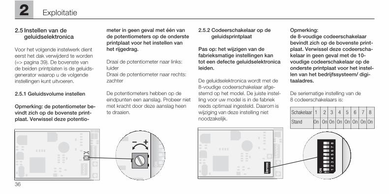
2.5 Instellen van de geluidselektronica
Voor het volgende instelwerk dienteerst het dak verwijderd te worden (=> pagina 39). De bovenste van de beiden printplaten is de geluids-generator waarop u de volgendeinstellingen kunt uitvoeren.
2.5.1 Geluidsvolume instellen
Opmerking: de potentiometer be-vindt zich op de bovenste print-plaat. Verwissel deze potentio-
meter in geen geval met één vande potentiometers op de ondersteprintplaat voor het instellen vanhet rijgedrag.
Draai de potentiometer naar links: luiderDraai de potentiometer naar rechts:zachter
De potentiometers hebben op deeindpunten een aanslag. Probeer nietmet kracht door deze aanslag heente draaien.
2.5.2 Codeerschakelaar op de geluidsprintplaat
Pas op: het wijzigen van defabrieksmatige instellingen kan tot een defecte geluidselektronicaleiden.
De geluidselektronica wordt met de8-voudige codeerschakelaar afge-stemd op het model. De juiste instel-ling voor uw model is in de fabriekreeds optimaal ingesteld. Daarom iswijziging van deze instelling nietnoodzakelijk.
Opmerking: de 8-voudige codeerschakelaarbevindt zich op de bovenste print-plaat. Verwissel deze codeerscha-kelaar in geen geval met de 10-voudige codeerschakelaar op deonderste printplaat voor het instel-len van het bedrijfssysteem/ digi-taaladres.
De seriematige instelling van de 8 codeerschakelaars is:
Schakelaar 1 2 3 4 5 6 7 8
Stand On On On On On On On On
2 Exploitatie
36
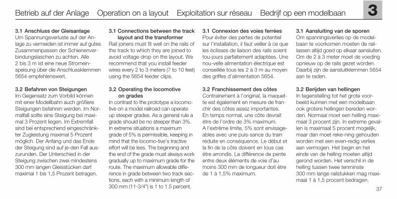
3.1 Anschluss der GleisanlageUm Spannungsverluste auf der An-lage zu vermeiden ist immer auf gutesZusammenpassen der Schienenver-bindungslaschen zu achten. Alle2 bis 3 m ist eine neue Stromein-speisung über die Anschlussklemmen5654 empfehlenswert.
3.2 Befahren von SteigungenIm Gegensatz zum Vorbild könnenmit einer Modellbahn auch größereSteigungen befahren werden. Im Nor-malfall sollte eine Steigung bei maxi-mal 3 Prozent liegen. Im Extremfallsind bei entsprechend eingeschränk-ter Zugleistung maximal 5 Prozentmöglich. Der Anfang und das Endeder Steigung sind auf je-den Fall aus-zurunden. Der Unterschied in derSteigung zwischen zwei mindestens300 mm langen Gleisstücken darfmaximal 1 bis 1,5 Prozent betragen.
3.1 Connections between the tracklayout and the transformer
Rail joiners must fit well on the rails ofthe track to which they are joined toavoid voltage drop on the layout. Werecommend that you install feederwires every 2 to 3 meters (7 to 10 feet)using the 5654 feeder clips.
3.2 Operating the locomotive on grades
In contrast to the prototype a locomo-tive on a model railroad can operateup steeper grades. As a general rule agrade should be no steeper than 3%.In extreme situations a maximumgrade of 5% is permissible, keeping inmind that the locomo-tive’s tractiveeffort will be less. The beginning andthe end of the grade must always workgradually up to maximum grade for theroute. The maximum allowable diffe-rence in grade between two track sec-tions, each with a minimum length of300 mm (11-3/4") is 1 to 1.5 percent.
3.1 Connexion des voies ferréesPour éviter des pertes de potentielsur l’installation, il faut veiller à ce queles éclisses de liaison des rails soienttou-jours parfaitement adaptées. Unenou-velle alimentation électrique estconseillée tous les 2 à 3 m au moyendes griffes d’alimentation 5654.
3.2 Franchissement des côtesContrairement à l’original, la maquet-te est également en mesure de fran-chir des côtes assez importantes.En temps normal, une côte devraitétre de l’ordre de 3% maximum.A l’extrême limite, 5% sont envisage-ables avec une puis-sance du trainréduite en conséquence. Le début etla fin de la côte doivent en tous casétre arrondis. La différence de penteentre deux éléments de voie d’aumoins 300 mm de longueur doit étrede 1 à 1,5% maximum.
3.1 Aansluiting van de sporenOm spanningsverlies op de model-baan te voorkomen moeten de rail-lassen altijd goed op elkaar aansluiten.Om de 2 à 3 meter moet de voedingopnieuw op de rails gezet worden.Daarbij zijn de aansluitklemmen 5654aan te raden.
3.2 Berijden van hellingenIn tegenstelling tot het grote voor-beeld kunnen met een modelbaanook grotere hellingen bereden wor-den. Normaal moet een helling maxi-maal 3 procent zijn. In extreme geval-len is maximaal 5 procent mogelijk,maar dan moet reke-ning gehoudenworden met een even-redig verliesaan vermogen. Het begin en heteinde van de helling moeten altijdgerond worden. Het verschil in dehelling tussen twee tenminste300 mm lange railstukken mag maxi-maal 1 à 1,5 procent bedragen.
3
37
Betrieb auf der Anlage Operation on a layout Exploitation sur réseau Bedrijf op een modelbaan
38
3 Betrieb auf der Anlage Operation on a layout Exploitation sur réseau Bedrijf op een modelbaan
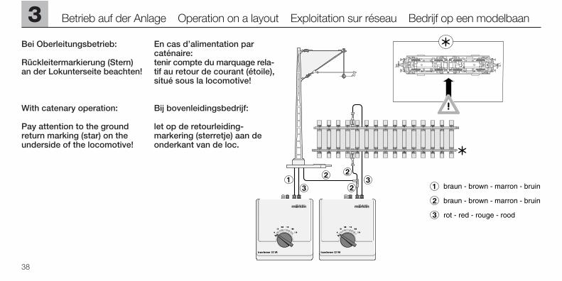
Bei Oberleitungsbetrieb:
Rückleitermarkierung (Stern)an der Lokunterseite beachten!
With catenary operation:
Pay attention to the groundreturn marking (star) on theunderside of the locomotive!
En cas d’alimentation parcaténaire: tenir compte du marquage rela-tif au retour de courant (étoile),situé sous la locomotive!
Bij bovenleidingsbedrijf:
let op de retourleiding-markering (sterretje) aan deonderkant van de loc.
4Wartung Maintenance Entretien Onderhoud
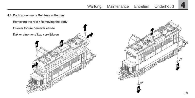
4.1 Dach abnehmen / Gehäuse entfernen
Removing the roof / Removing the body
Enlever toiture / enlever caisse
Dak er afnemen / kap verwijderen
39
4 Wartung Maintenance Entretien Onderhoud
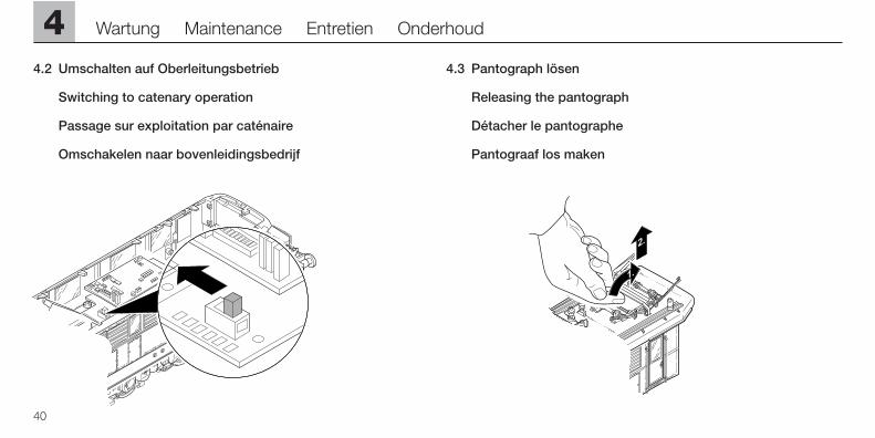
4.2 Umschalten auf Oberleitungsbetrieb
Switching to catenary operation
Passage sur exploitation par caténaire
Omschakelen naar bovenleidingsbedrijf
40
4.3 Pantograph lösen
Releasing the pantograph
Détacher le pantographe
Pantograaf los maken
4
41
Wartung Maintenance Entretien Onderhoud
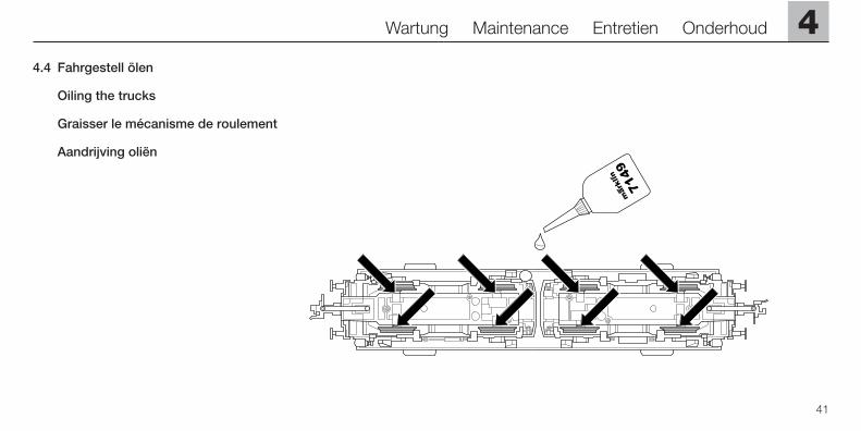
4.4 Fahrgestell ölen
Oiling the trucks
Graisser le mécanisme de roulement
Aandrijving oliën
42
4 Wartung Maintenance Entretien Onderhoud
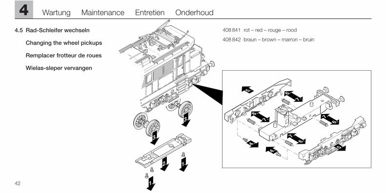
4.5 Rad-Schleifer wechseln
Changing the wheel pickups
Remplacer frotteur de roues
Wielas-sleper vervangen
408 841 rot – red – rouge – rood
408 842 braun – brown – marron – bruin
4Wartung Maintenance Entretien Onderhoud
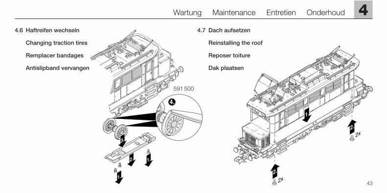
4.7 Dach aufsetzen
Reinstalling the roof
Reposer toiture
Dak plaatsen
43
4.6 Haftreifen wechseln
Changing traction tires
Remplacer bandages
Antislipband vervangen
591 500
This device complies with Part 15 of the FCC Rules. Operation is subject to the following two conditions:(1) This device may not cause harmful interference, and(2) this device must accept any interference received, including
interference that may cause undesired operation.
Gebr. Märklin & Cie. GmbHPostfach 8 60D-73008 Göppingenwww.maerklin.com
651 207 08 03 naÄnderungen vorbehalten