AWDP Top Level Design - KNMIprojects.knmi.nl/.../nwpsafknds004_awdp_topleveldesign_v3.0.01.pdf ·...
79
Document NWPSAF-KN-DS-004 Version 3.0.01 February 2017 AWDP Top Level Design Anton Verhoef, Jur Vogelzang, Jeroen Verspeek and Ad Stoffelen KNMI, De Bilt, the Netherlands
-
Upload
truongduong -
Category
Documents
-
view
223 -
download
0
Transcript of AWDP Top Level Design - KNMIprojects.knmi.nl/.../nwpsafknds004_awdp_topleveldesign_v3.0.01.pdf ·...

Document NWPSAF-KN-DS-004 Version 3.0.01 February 2017
AWDP Top Level Design Anton Verhoef, Jur Vogelzang, Jeroen Verspeek and Ad Stoffelen KNMI, De Bilt, the Netherlands
NWP SAF
AWDP Top Level Design Doc ID : NWPSAF-KN-DS-004 Version : 3.0.01 Date : February 2017
AWDP Top Level Design
KNMI, De Bilt, the Netherlands
This documentation was developed within the context of the EUMETSAT Satellite Application Facility on Numerical Weather Prediction (NWP SAF), under the Cooperation Agreement dated 29 June, 2011, between EUMETSAT and the Met Office, UK, by one or more partners within the NWP SAF. The partners in the NWP SAF are the Met Office, ECMWF, KNMI and Météo France.
Copyright 2017, EUMETSAT, All Rights Reserved.
Change record
Version Date Author / changed by Remarks
1.0j Jun 2007 Anton Verhoef First draft
1.0k Oct 2007 Anton Verhoef Adapted for AWDP version 1.0k
1.0.13 Mar 2008 Anton Verhoef Adapted for AWDP version 1.0.13
1.0.14 Oct 2008 Anton Verhoef First version for external review
1.0.16 Dec 2008 Anton Verhoef Modified according to DRI comments
1.1 Jan 2010 Anton Verhoef Removed a few typo’s and corrected some of the diagrams in the appendices for AWDP v1.1
2.0 Aug 2010 Anton Verhoef Modified for AWDP v2.0; added section 3.5.3, changed sections 2.3, 2.3.4, 2.4, Chapter 9 and Appendix B4
2.0.01 Nov 2010 Anton Verhoef Modified according to DRI comments
2.2 Jun 2013 Anton Verhoef Version for AWDP v2.2
2.3 Feb 2014 Anton Verhoef Version for AWDP v2.3
2.4 Jun 2016 Anton Verhoef, Jur Vogelzang
Version for AWDP v2.4, split original UM into UM, PS and TLD docs
3.0 Feb 2017 Jur Vogelzang Version for AWDP v3.0
NWP SAF
AWDP Top Level Design Doc ID : NWPSAF-KN-DS-004 Version : 3.0.01 Date : February 2017
Contents
CONTENTS .................................................................................................................................................... 1
INTRODUCTION ................................................................................................................................. 3 1
1.1 DESIGN DRIVERS ................................................................................................................................. 3 1.2 CONVENTIONS ..................................................................................................................................... 4
PROGRAM DESIGN ........................................................................................................................... 5 2
2.1 TOP LEVEL DESIGN ............................................................................................................................. 5 Main program ............................................................................................................................ 5 2.1.1 Layered model structure ............................................................................................................ 6 2.1.2 Data Structure............................................................................................................................ 7 2.1.3 Quality flagging and error handling .......................................................................................... 8 2.1.4 Verbosity .................................................................................................................................... 8 2.1.5
2.2 MODULE DESIGN FOR GENSCAT LAYER ............................................................................................... 9 Module inversion ....................................................................................................................... 9 2.2.1 Module ambrem ......................................................................................................................... 9 2.2.2 Module icemodel ........................................................................................................................ 9 2.2.3 Module Bufrmod ........................................................................................................................ 9 2.2.4 Module gribio_module ............................................................................................................. 10 2.2.5 Support modules ...................................................................................................................... 10 2.2.6
2.3 MODULE DESIGN FOR PROCESS LAYER .............................................................................................. 11 Module awdp_data .................................................................................................................. 11 2.3.1 Module awdp_bufr ................................................................................................................... 17 2.3.2 Module awdp_pfs ..................................................................................................................... 18 2.3.3 Module awdp_szf ..................................................................................................................... 18 2.3.4 Module awdp_prepost .............................................................................................................. 19 2.3.5 Module awdp_calibrate ........................................................................................................... 20 2.3.6 Module awdp_grib ................................................................................................................... 21 2.3.7 Module awdp_inversion ........................................................................................................... 21 2.3.8 Module awdp_ambrem............................................................................................................. 22 2.3.9 Module awdp_icemodel ........................................................................................................... 22 2.3.10 Module awdp............................................................................................................................ 23 2.3.11
INVERSION MODULE ..................................................................................................................... 24 3
3.1 BACKGROUND ................................................................................................................................... 24 3.2 ROUTINES ......................................................................................................................................... 24 3.3 ANTENNA DIRECTION ........................................................................................................................ 26
AMBIGUITY REMOVAL MODULE .............................................................................................. 27 4
4.1 AMBIGUITY REMOVAL ...................................................................................................................... 27 4.2 MODULE AMBREM .............................................................................................................................. 27 4.3 MODULE BATCHMOD ........................................................................................................................ 28 4.4 THE KNMI 2DVAR SCHEME ............................................................................................................ 31
Introduction ............................................................................................................................. 31 4.4.1 Data structure, interface and initialisation .............................................................................. 31 4.4.2 Reformulation and transformation........................................................................................... 33 4.4.3 Module CostFunction............................................................................................................... 34 4.4.4 Adjoint method ......................................................................................................................... 34 4.4.5 Structure Functions .................................................................................................................. 34 4.4.6

NWP SAF
AWDP Top Level Design Doc ID : NWPSAF-KN-DS-004 Version : 3.0.01 Date : February 2017
2
Minimization ............................................................................................................................ 35 4.4.7 SingletonFFT_Module ............................................................................................................. 35 4.4.8
4.5 THE PRESCAT SCHEME ...................................................................................................................... 36
MODULE ICEMODELMOD ............................................................................................................. 37 5
5.1 BACKGROUND ................................................................................................................................... 37 5.2 ROUTINES ......................................................................................................................................... 38 5.3 DATA STRUCTURES ........................................................................................................................... 38
MODULE BUFRMOD ........................................................................................................................ 40 6
6.1 BACKGROUND ................................................................................................................................... 40 6.2 ROUTINES ......................................................................................................................................... 40 6.3 DATA STRUCTURES ........................................................................................................................... 42 6.4 LIBRARIES ......................................................................................................................................... 43 6.5 BUFR TABLE ROUTINES .................................................................................................................... 44 6.6 CENTRE SPECIFIC MODULES .............................................................................................................. 44
MODULE GRIBIO_MODULE .......................................................................................................... 45 7
7.1 BACKGROUND ................................................................................................................................... 45 7.2 ROUTINES ......................................................................................................................................... 45 7.3 DATA STRUCTURES ........................................................................................................................... 47 7.4 LIBRARIES ......................................................................................................................................... 48
REFERENCES ............................................................................................................................................. 49
APPENDIX A: CALLING TREE FOR AWDP......................................................................................... 51
APPENDIX B1: CALLING TREE FOR INVERSION ROUTINES ....................................................... 62
APPENDIX B2: CALLING TREE FOR AR ROUTINES ....................................................................... 64
APPENDIX B3: CALLING TREE FOR BUFR ROUTINES .................................................................. 68
APPENDIX B4: CALLING TREE FOR GRIB ROUTINES ................................................................... 70 APPENDIX B5: CALLING TREE FOR PFS ROUTINES ...................................................................... 72
APPENDIX B6: CALLING TREE FOR ASCAT-5.6 ROUTINES ......................................................... 75
APPENDIX B7: CALLING TREE FOR ICE MODEL ROUTINES ...................................................... 76
APPENDIX C: ACRONYMS ...................................................................................................................... 77
NWP SAF
AWDP Top Level Design Doc ID : NWPSAF-KN-DS-004 Version : 3.0.01 Date : February 2017
3
Introduction 1
The ASCAT Wind Data Processor (AWDP) is a software package mainly written in Fortran 90 with some parts in C for handling data from the Advanced Scatterometer (ASCAT) and European Remote Sensing satellite (ERS) scatterometer instruments. This document is the Top Level Design (TLD) of the AWDP software package and it also contains the Module Design. Section 2 provides information on the general design of the AWDP software. Section 3 and further provide information on the individual modules that are part of AWDP.
More information about AWDP can be found in several other documents. The User Manual and Reference Guide (UM) [1] contains more details about the installation and use of the AWDP package. The Product Specification (PS) [2] provides information on the purpose, outputs, inputs, system requirements and functionality of the AWDP software. Reading the UM and the PS should provide sufficient information to the user who wants to apply the AWDP program as a black box. This TLD document is of interest to developers and users who need more specific information on how the processing is done.
Please note that any questions or problems regarding the installation or use of AWDP can be addressed at the NWP SAF helpdesk at http://nwpsaf.eu/.
1.1 Design drivers A user requirements assessment is performed to verify the user requirement for the improvements available in the new version. AWDP users from NOAA, MetNo, IPMA, the OSI SAF and many others require optimised spatial resolution for depicting mesoscale flow characteristics in dynamical conditions, such as near moist convection, polar lows, tropical hurricanes, or low-level coastal jets. Moreover, through the OSI SAF and CMEMS products, these improvements allow ocean forcing (studies) on the ocean eddy scale. The improved ASCAT spatial resolution product (true spatial resolution 19 km), posted at an irregular grid of 5.6 km has been brought forward from CDOP-3 planned work on spatial resolution improvements. The improvement in spatial representation of the AWDP furthermore includes better 2D Variational Ambiguity Removal (2DVAR) by exploiting Numerical Structure Functions in 2DVAR. This follows results of an Associate Scientist mission by Wenming Lin, ICM, which shows NSF to be more valuable than originally anticipated.
AWDP users from ECMWF (also C3S), NOAA, NASA and others stressed the relevance and appreciation of the improvements to AWDP for their requirements on the intercalibration with other scatterometers, notably the ESA ERS scatterometers, which AWDP now supports. This allows the production of consistent long-term Climate Data Records (CDR) since 1991 of ocean vector winds and wind stresses, an Essential Climate Variable (ECV), which is a high user priority. A consistent ocean wind vector climatology is essential in depicting any changes in air-sea interaction over 71% of the earth’s surface.
NWP SAF
AWDP Top Level Design Doc ID : NWPSAF-KN-DS-004 Version : 3.0.01 Date : February 2017
4
Another high user priority is an improved coastal processing, but this depends on the provision of the EUMETSAT L1B land contributions flag, and has not been made available yet. This development is being incorporated into spatial resolution improvements planned for CDOP-3.
1.2 Conventions Names of physical quantities (e.g., wind speed components u and v), modules (e.g. BufrMod), subroutines and identifiers are printed italic.
Names of directories and subdirectories (e.g. awdp/src), files (e.g. awdp.F90), and commands (e.g. awdp -f input) are printed in Courier. Software systems in general are addressed using the normal font (e.g. AWDP, genscat).
Hyperlinks are printed in blue and underlined (e.g. http://www.knmi.nl/scatterometer/).
Numbers between square brackets refer to references (e.g. [3]).

NWP SAF
AWDP Top Level Design Doc ID : NWPSAF-KN-DS-004 Version : 3.0.01 Date : February 2017
5
Program Design 2
In this chapter, the design of the AWDP software package is described in detail. Readers to whom only a summary will suffice are referred to the Top Level Design (TLD) in section 4.1. Readers who really want to know the very detail should not only read the complete chapter, but also the documentation within the code. Some more detailed information is also given in the NWPSAF Technical Reports listed in the references.
2.1 Top Level Design
Main program 2.1.1
The main program, AWDP, (file awdp in the awdp/src directory) is a Unix (Linux) executable which processes ASCAT BUFR, ASCAT PFS, or ERS BUFR input files. The main output consists of BUFR files. The output BUFR messages are always in the ASCAT BUFR format, for a list of descriptors see appendix A in the Product Specification [2]. The user may provide arguments and parameters according to Unix command line standards. The purpose of the different options is described in the User Manual [1].
When executed, AWDP logs information on the standard output. The detail of this information may be set with the verbosity flag. The baseline of processing is shown in Figure 2.1, but note that not all of these steps are always invoked. Some of them may be skipped, depending on the command line options supplied to AWDP. A more detailed representation of the AWDP structure is given in Appendices A and B.
The first step is to process the arguments given at the command line using the genscat Compiler_Features module. Next, AWDP reads the input file specified in the arguments. The BUFR messages or PFS records are read and mapped onto the AWDP data structure, see subsection 2.1.3. As part of the pre-processing a similar AWDP data structure is created for the output. Subsequently, the input data are sorted with respect to data acquisition time, duplicate rows are merged and the output data structure is filled with level 1b (σ 0 related) data. Then, the NWP GRIB data (wind forecasts, land-sea mask and sea surface temperature) are read and the data are collocated with the Wind Vector Cells. The next steps are the inversion and the ambiguity removal. These steps are performed on the output data. The program ends with the post-processing step (which includes some conversions and the monitoring) and the mapping of the output data structure onto BUFR messages of the BUFR output file. The different stages in the processing correspond directly to specific modules of the code. These modules form the process layer, see section 2.3.

NWP SAF
AWDP Top Level Design Doc ID : NWPSAF-KN-DS-004 Version : 3.0.01 Date : February 2017
6
Figure 2.1 Baseline of the ASCAT Wind Data Processor
Layered model structure 2.1.2
AWDP is a Fortran 90 software package consisting of several Fortran 90 modules which are linked after their individual compilation. The AWDP software is set up from two layers of software modules. The purpose of the layer structure is to divide the code into generic scatterometer processing software and ASCAT specific software. Details on the individual modules can be found in sections 2.2 and 2.3.
The first layer (the process layer) consists of modules which serve the main steps of the process. Each module contains code for performing one or more of the specific tasks. These tasks are briefly described in table 2.1. A more elaborate description is given in section 2.3. The first module listed, awdp_data is a general support module. This module is used by the other modules of the process layer for the inclusion of definitions of the data structures and the support routines.
The second module layer is the genscat layer. The genscat module classes (i.e., groups of modules) used in the AWDP software package are listed in table 2.2. The genscat package is a set of generic modules which can be used to assemble processors as well as pre, and post-processing tools for different scatterometer instruments available to the user community. A short description of the main (interface) modules is given in section 2.2. The most important classes of modules are related to the inversion processing step (chapter 3), the Ambiguity Removal step (chapter 4), the BUFR file handling (chapter 6), and the GRIB file handling (chapter 7). The genscat modules are located in subdirectory genscat.
Process arguments
Read input data
Pre-processing
Read full resolution data
Read/collocate GRIB data
Inversion
Ice screening
Ambiguity Removal
Post-processing
NWP SAF
AWDP Top Level Design Doc ID : NWPSAF-KN-DS-004 Version : 3.0.01 Date : February 2017
7
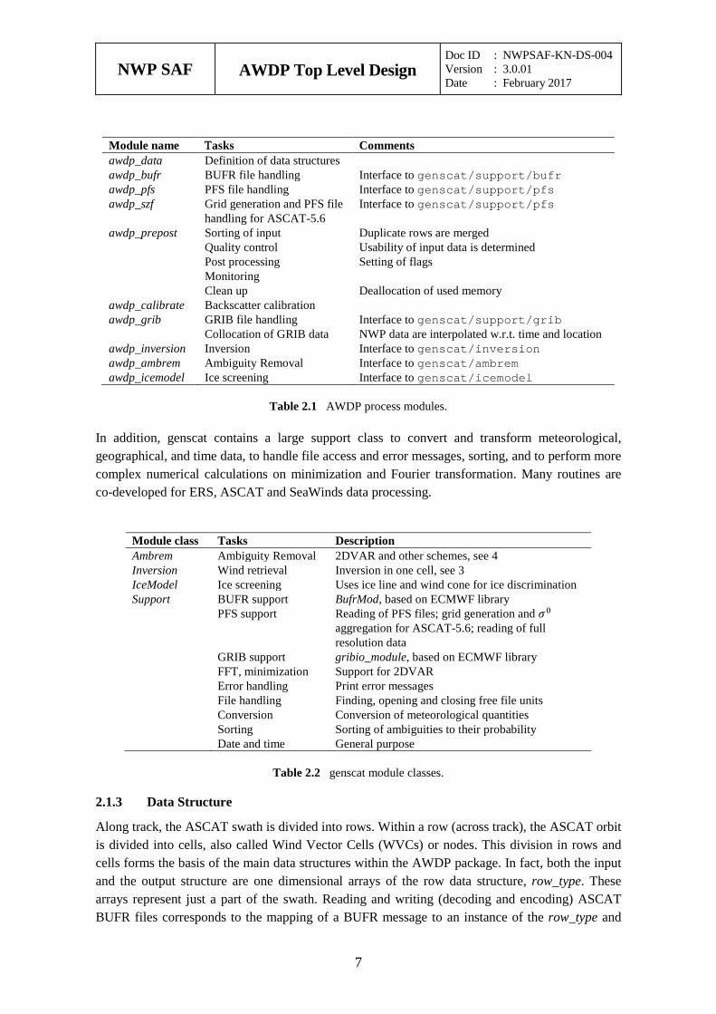
Module name Τasks Comments awdp_data Definition of data structures awdp_bufr BUFR file handling Interface to genscat/support/bufr awdp_pfs PFS file handling Interface to genscat/support/pfs awdp_szf Grid generation and PFS file
handling for ASCAT-5.6 Interface to genscat/support/pfs
awdp_prepost Sorting of input Quality control Post processing Monitoring Clean up
Duplicate rows are merged Usability of input data is determined Setting of flags Deallocation of used memory
awdp_calibrate Backscatter calibration awdp_grib GRIB file handling
Collocation of GRIB data Interface to genscat/support/grib NWP data are interpolated w.r.t. time and location
awdp_inversion Inversion Interface to genscat/inversion awdp_ambrem Ambiguity Removal Interface to genscat/ambrem awdp_icemodel Ice screening Interface to genscat/icemodel
Table 2.1 AWDP process modules.
In addition, genscat contains a large support class to convert and transform meteorological, geographical, and time data, to handle file access and error messages, sorting, and to perform more complex numerical calculations on minimization and Fourier transformation. Many routines are co-developed for ERS, ASCAT and SeaWinds data processing.
Module class Tasks Description Ambrem Ambiguity Removal 2DVAR and other schemes, see 4 Inversion Wind retrieval Inversion in one cell, see 3 IceModel Ice screening Uses ice line and wind cone for ice discrimination Support BUFR support
PFS support GRIB support FFT, minimization Error handling File handling Conversion Sorting Date and time
BufrMod, based on ECMWF library Reading of PFS files; grid generation and 𝜎𝜎0 aggregation for ASCAT-5.6; reading of full resolution data gribio_module, based on ECMWF library Support for 2DVAR Print error messages Finding, opening and closing free file units Conversion of meteorological quantities Sorting of ambiguities to their probability General purpose
Table 2.2 genscat module classes.
Data Structure 2.1.3
Along track, the ASCAT swath is divided into rows. Within a row (across track), the ASCAT orbit is divided into cells, also called Wind Vector Cells (WVCs) or nodes. This division in rows and cells forms the basis of the main data structures within the AWDP package. In fact, both the input and the output structure are one dimensional arrays of the row data structure, row_type. These arrays represent just a part of the swath. Reading and writing (decoding and encoding) ASCAT BUFR files corresponds to the mapping of a BUFR message to an instance of the row_type and
NWP SAF
AWDP Top Level Design Doc ID : NWPSAF-KN-DS-004 Version : 3.0.01 Date : February 2017
8
vice versa.
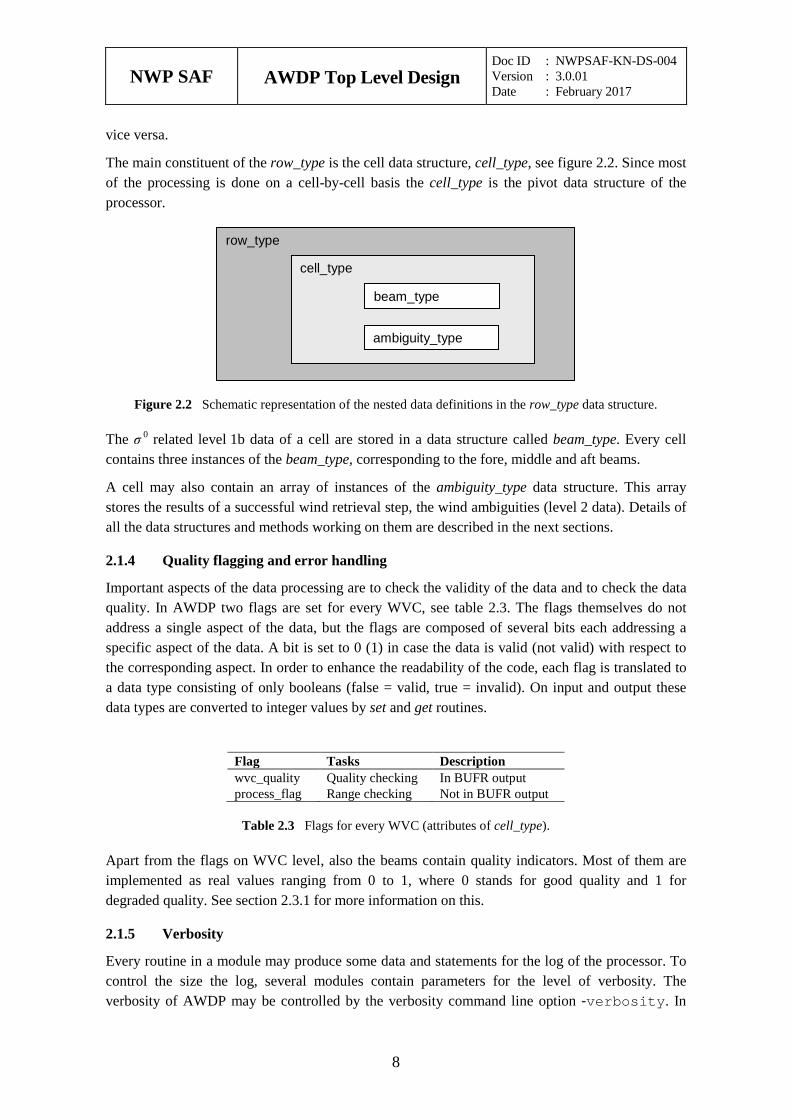
The main constituent of the row_type is the cell data structure, cell_type, see figure 2.2. Since most of the processing is done on a cell-by-cell basis the cell_type is the pivot data structure of the processor.
Figure 2.2 Schematic representation of the nested data definitions in the row_type data structure.
The σ 0 related level 1b data of a cell are stored in a data structure called beam_type. Every cell contains three instances of the beam_type, corresponding to the fore, middle and aft beams.
A cell may also contain an array of instances of the ambiguity_type data structure. This array stores the results of a successful wind retrieval step, the wind ambiguities (level 2 data). Details of all the data structures and methods working on them are described in the next sections.
Quality flagging and error handling 2.1.4
Important aspects of the data processing are to check the validity of the data and to check the data quality. In AWDP two flags are set for every WVC, see table 2.3. The flags themselves do not address a single aspect of the data, but the flags are composed of several bits each addressing a specific aspect of the data. A bit is set to 0 (1) in case the data is valid (not valid) with respect to the corresponding aspect. In order to enhance the readability of the code, each flag is translated to a data type consisting of only booleans (false = valid, true = invalid). On input and output these data types are converted to integer values by set and get routines.
Flag Tasks Description wvc_quality Quality checking In BUFR output process_flag Range checking Not in BUFR output
Table 2.3 Flags for every WVC (attributes of cell_type).
Apart from the flags on WVC level, also the beams contain quality indicators. Most of them are implemented as real values ranging from 0 to 1, where 0 stands for good quality and 1 for degraded quality. See section 2.3.1 for more information on this.
Verbosity 2.1.5
Every routine in a module may produce some data and statements for the log of the processor. To control the size the log, several modules contain parameters for the level of verbosity. The verbosity of AWDP may be controlled by the verbosity command line option -verbosity. In
row_type
cell_type
beam_type
ambiguity_type
NWP SAF
AWDP Top Level Design Doc ID : NWPSAF-KN-DS-004 Version : 3.0.01 Date : February 2017
9
general, there are three levels of verbosity specified:
≤ -1: be as quiet as possible;
0: only report top level processing information;
≥ 1: report additional information.
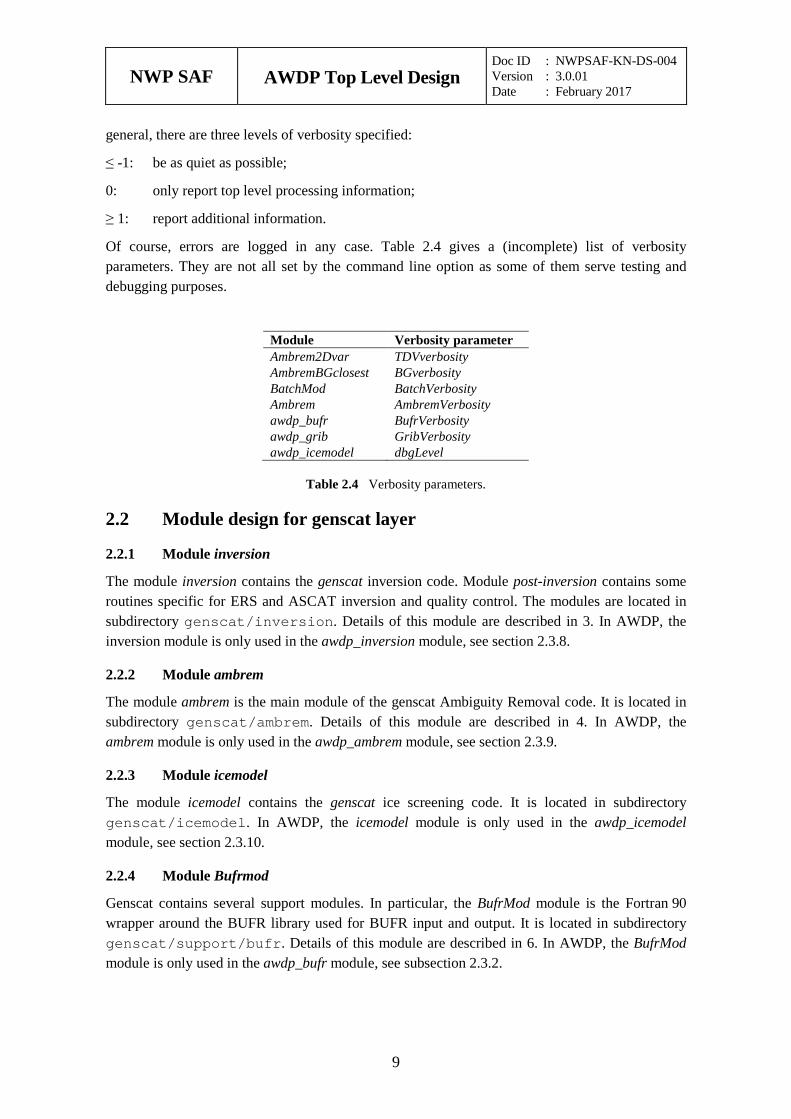
Of course, errors are logged in any case. Table 2.4 gives a (incomplete) list of verbosity parameters. They are not all set by the command line option as some of them serve testing and debugging purposes.
Module Verbosity parameter Ambrem2Dvar TDVverbosity AmbremBGclosest BGverbosity BatchMod BatchVerbosity Ambrem AmbremVerbosity awdp_bufr BufrVerbosity awdp_grib GribVerbosity awdp_icemodel dbgLevel
Table 2.4 Verbosity parameters.
2.2 Module design for genscat layer
Module inversion 2.2.1
The module inversion contains the genscat inversion code. Module post-inversion contains some routines specific for ERS and ASCAT inversion and quality control. The modules are located in subdirectory genscat/inversion. Details of this module are described in 3. In AWDP, the inversion module is only used in the awdp_inversion module, see section 2.3.8.
Module ambrem 2.2.2
The module ambrem is the main module of the genscat Ambiguity Removal code. It is located in subdirectory genscat/ambrem. Details of this module are described in 4. In AWDP, the ambrem module is only used in the awdp_ambrem module, see section 2.3.9.
Module icemodel 2.2.3
The module icemodel contains the genscat ice screening code. It is located in subdirectory genscat/icemodel. In AWDP, the icemodel module is only used in the awdp_icemodel module, see section 2.3.10.
Module Bufrmod 2.2.4
Genscat contains several support modules. In particular, the BufrMod module is the Fortran 90 wrapper around the BUFR library used for BUFR input and output. It is located in subdirectory genscat/support/bufr. Details of this module are described in 6. In AWDP, the BufrMod module is only used in the awdp_bufr module, see subsection 2.3.2.
NWP SAF
AWDP Top Level Design Doc ID : NWPSAF-KN-DS-004 Version : 3.0.01 Date : February 2017
10
Module gribio_module 2.2.5
The gribio_module module is the Fortran 90 wrapper around the GRIB library used for GRIB input and collocation of the NWP data with the scatterometer data. It is located in subdirectory genscat/support/grib. Details of this module are described in 7. In AWDP, the gribio_module module is used in the awdp_grib and awdp_pfs modules, see subsection 2.3.7.
Support modules 2.2.6
Subdirectory genscat/support contains more support modules besides Bufrmod and gribio_module. The KNMI 2DVAR Ambiguity Removal method requires minimization of a cost function and numerical Fourier transformation. These routines are located in subdirectories BFGS and singletonfft, respectively, and are discussed in more detail in section 4.4.
Subdirectory Compiler_Features contains module Compiler_Features for handling some compiler specific issues, mainly with respect to command line argument handling. The Makefile in this directory compiles on of the available source files, depending on the Fortran compiler used.
Subdirectory constants contains a small module constants with some mathematical and physical constants.
Subdirectory convert contains module convert for the conversion of meteorological and geographical quantities, e.g. the conversion of wind speed and direction into u and v components and vice versa.
Subdirectory datetime contains module DateTimeMod for date and time conversions. AWDP only uses routines GetElapsedSystemTime (for calculating the running time of the various processing steps), and julian2ymd and ymd2julian (for conversion between Julian day number and day, month and year). Module DateTimeMod needs modules ErrorHandler and numerics.
Subdirectory ErrorHandler contains module ErrorHandler for error management. This module is needed by module DateTimeMod.
Subdirectory file contains module LunManager for finding, opening and closing free logical units in Fortran. AWDP uses only routines get_lun and free_lun for opening and closing of a logical unit, respectively.
Subdirectory num contains module numerics for defining data types and handling missing values, for instance in the BUFR library. This module is needed by many other modules.
Subdirectory pfs contains modules pfs_ascat and szf_ascat for opening, reading and closing of files in PFS format. Further, szf_ascat contains routines for generating a grid of wind vector cells synchronised to the ASCAT mid beam pulse pattern and calculating the average radar cross sections (aggregation) for the ASCAT-5.6 product [3].
Subdirectory sort, contains module SortMod for sorting the rows according to their acquisition date and time, or the wind vector solutions according to their probability.
Subdirectory stringtools, finally, contains module StringTools for handling character strings.
NWP SAF
AWDP Top Level Design Doc ID : NWPSAF-KN-DS-004 Version : 3.0.01 Date : February 2017
11
2.3 Module design for process layer The process layer consists of the modules awdp_data, awdp_bufr, awdp_pfs, awdp_szf, awdp_prepost, awdp_calibrate, awdp_grib, awdp_inversion, awdp_icemodel and awdp_ambrem. The routines present in these modules are described in the next sections.
Module awdp_data 2.3.1
The module awdp_data contains all the important data types relevant for the processing. Elementary data types are introduced for the most basic data structures of the processing. These are e.g. wind_type and time_type. Using these data types (and of course the standard types as integer, real etc.), more complex (composed) data types are derived. Examples are beam_type, ambiguity_type, cell_type, and row_type. A complete description of all types is given below. The attributes of all these types have intentionally self-documenting names.
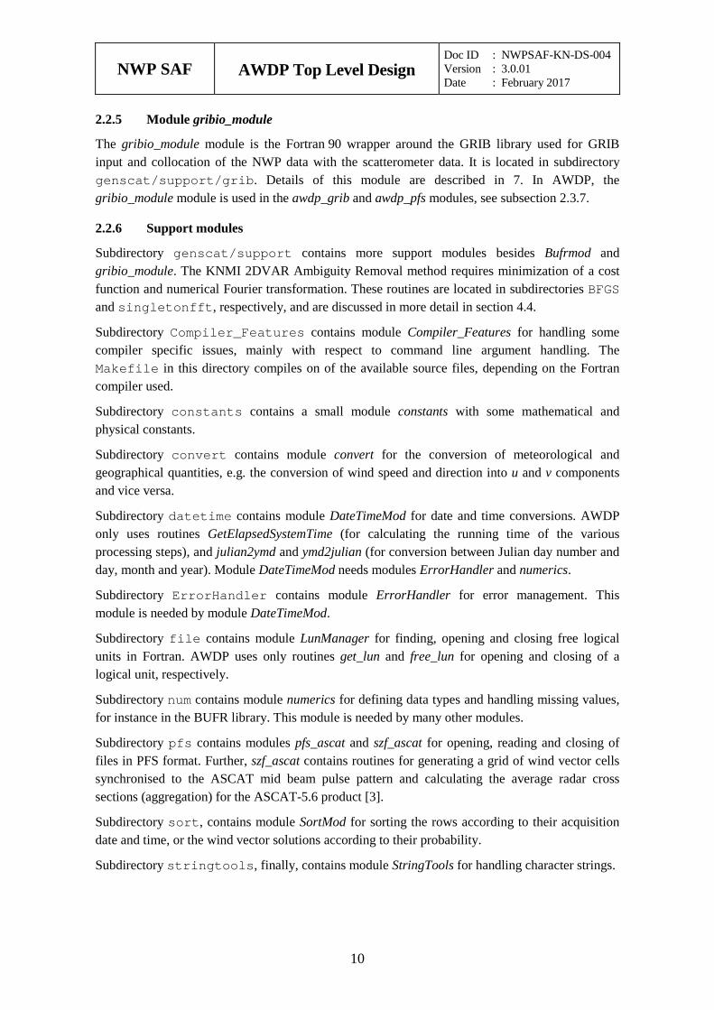
Ambiguity data: The ambiguity_type data type contains information on an individual ambiguity (wind vector solution). The attributes are listed in table 2.5. The routine init_ambiguity() sets all ambiguity data to missing. The routine print_ambiguity() may be used to print all ambiguity data.
Attribute Type Description wind wind_type Wind vector solution prob real Probability of wind vector solution conedistance real Distance of solution to the GMF
Table 2.5 Ambiguity data structure.
Beam data: Every WVC contains three beams. The information of every beam is stored in the data type beam_type. The attributes are listed in table 2.6. Most of the attributes are explained in detail in [4]. The routine init_beam() sets all beam data to missing and the routine test_beam checks if the data in the beam are within valid ranges. The routine print_beam() may be used to print all beam data.
Attribute Type Description identifier integer Beam number: 1 = fore, 2 = mid, 3 = aft incidence real Incidence angle (degrees, 0 is vertical, 90 is horizontal) azimuth real Radar look angle (degrees, counted clockwise from the south) sigma0 real Radar backscatter (σ 0) in dB noise_val real Noise value in % kp_estim_qual kp_estim_qual_type Flag related to the quality of the Kp estimate s0_usability integer Usability of σ 0: 0 = good, 1 = usable, 2 = bad synt_data_quantity real Amount of synthetic data in σ 0 (0..1) synt_data_quality real Quality of used synthetic data in σ 0 (0..1) orbit_quality real Satellite orbit and attitude quality (0..1) solar_reflec real Solar array reflection contamination in σ 0 (0..1) telemetry real Telemetry quality (0..1) land_frac real Land fraction in σ 0 (0..1) sigma0_corr real Correction applied to σ 0 from NOC or other corrections
Table 2.6 Beam data structure.
NWP SAF
AWDP Top Level Design Doc ID : NWPSAF-KN-DS-004 Version : 3.0.01 Date : February 2017
12
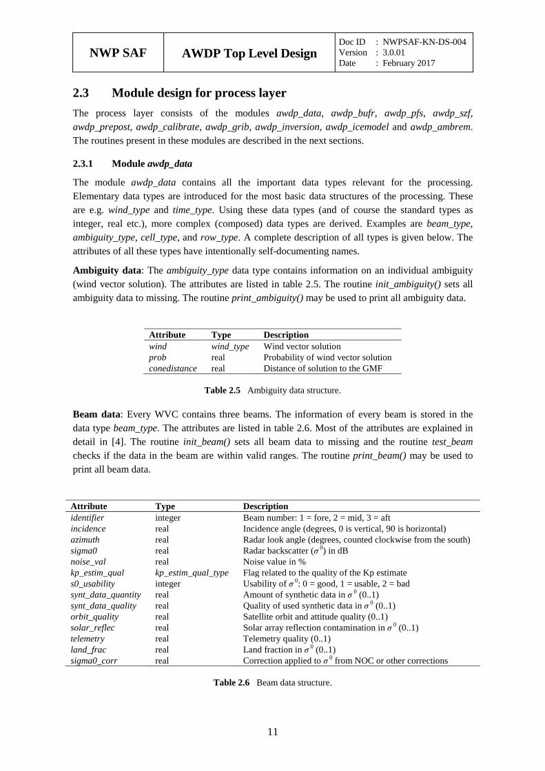
Cell Data: The cell_type data type is a key data type in AWDP, because many processing steps are done on a cell by cell basis. The attributes are listed in table 2.7. The routine init_cell() sets the cell data to missing values. Also the flags are set to missing. The routine test_cell() tests the validity of data. This routine sets the cell process flag. The routine print_cell() may be used to print the cell data.
Attribute Type Description centre_id integer Identification of originating/generating centre sub_centre_id integer Identification of originating/generating sub-centre software_id_l1b integer Software identification of level 1 processor satellite_id integer Satellite identifier sat_instruments integer Satellite instrument identifier sat_motion real Direction of motion of satellite time time_type Date and time of data acquisition lat real Latitude of WVC lon real Longitude of WVC pixel_size_hor real Distance between WVCs (meters) orbit_nr integer Orbit number node_nr integer Across track cell number height_atmosphere real Height of atmosphere used loss_unit_lenght real Loss per unit length of atmosphere beam_collocation beam_collocation_type Beam collocation flag beam (3) beam_type Beam data full_res full_res_type Averaged full resolution data software_id_sm integer Soil moisture information database_id integer Soil moisture information surface_sm real Soil moisture information surface_sm_err real Soil moisture information sigma0_40 real Soil moisture information sigma0_40_err real Soil moisture information slope_40 real Soil moisture information slope_40_err real Soil moisture information sm_sensitivity real Soil moisture information dry_backscatter real Soil moisture information wet_backscatter real Soil moisture information mean_surface_sm real Soil moisture information rain_fall_detect real Soil moisture information sm_corr_flag integer Soil moisture information sm_proc_flag integer Soil moisture information sm_quality real Soil moisture information snow_cov_frac real Soil moisture information froz_land_frac real Soil moisture information inund_wet_frac real Soil moisture information topo_complexity real Soil moisture information software_id_wind integer Software identification of level 2 wind processor generating_app integer Generating application of model information model_wind wind_type Model wind used for Ambiguity Removal ice_prob real Probability of ice ice_age real Ice age A-parameter wvc_quality wvc_quality_type WVC quality flag num_ambigs integer Number of ambiguities present in WVC selection integer Index of selected wind vector skill real Parameter used for PreScat Ambiguity Removal ambig (0..144) ambiguity_type Array of wind ambiguities ice icemodel_type Ice information
NWP SAF
AWDP Top Level Design Doc ID : NWPSAF-KN-DS-004 Version : 3.0.01 Date : February 2017
13
Attribute Type Description stress_param nwp_stress_param_type Wind stress information process_flag process_flag_type Processing flag level_of_input integer Level of input data (1 or 2)
Table 2.7 Cell data structure.
All soil moisture information is read from the input BUFR file into the cell data structure and not used within the program. It is written to the output BUFR file at the end of the processing.
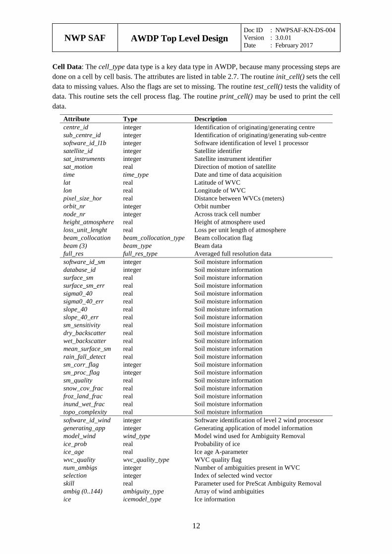
Full resolution data: The full_res_type contains average full resolution data, read from a PFS file, which are used to replace the 25-km or 12.5-km beam data. The attributes are listed in table 2.8. The routine init_full_res() sets the full resolution averaged data to zero. The routine print_full_res() may be used to print the full resolution data.
Attribute Type Description count_tot integer Number of full res measurements used lat real Mean value of full res lats lon real Mean value of full res lons count_fore integer Number of full res fore beams used incidence_fore real Mean value of full res values azimuth_fore real Mean value of full res values sigma0_fore real Mean value of full res values sigma0_sq_fore real Sum of squares land_frac_fore real Mean value of full res values count_mid integer Number of full res mid beams used incidence_mid real Mean value of full res values azimuth_mid real Mean value of full res values sigma0_mid real Mean value of full res values sigma0_sq_mid real Sum of squares land_frac_mid real Mean value of full res values count_aft integer Number of full res aft beams used incidence_aft real Mean value of full res values azimuth_aft real Mean value of full res values sigma0_aft real Mean value of full res values sigma0_sq_aft real Sum of squares land_frac_aft real Mean value of full res values
Table 2.8 Full res data structure.
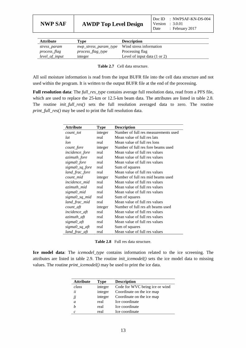
Ice model data: The icemodel_type contains information related to the ice screening. The attributes are listed in table 2.9. The routine init_icemodel() sets the ice model data to missing values. The routine print_icemodel() may be used to print the ice data.
Attribute Type Description class integer Code for WVC being ice or wind ii integer Coordinate on the ice map jj integer Coordinate on the ice map a real Ice coordinate b real Ice coordinate c real Ice coordinate
NWP SAF
AWDP Top Level Design Doc ID : NWPSAF-KN-DS-004 Version : 3.0.01 Date : February 2017
14
Attribute Type Description dIce real Distance to the ice line wind_sol integer Wind solution to be used
Table 2.9 Ice model data structure.
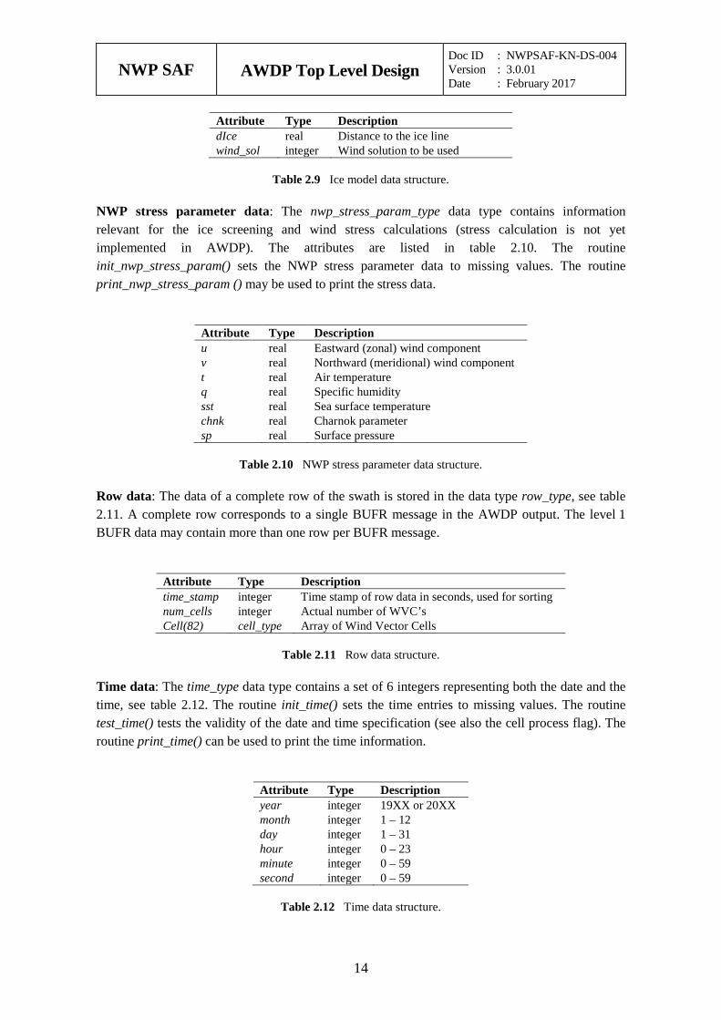
NWP stress parameter data: The nwp_stress_param_type data type contains information relevant for the ice screening and wind stress calculations (stress calculation is not yet implemented in AWDP). The attributes are listed in table 2.10. The routine init_nwp_stress_param() sets the NWP stress parameter data to missing values. The routine print_nwp_stress_param () may be used to print the stress data.
Attribute Type Description u real Eastward (zonal) wind component v real Northward (meridional) wind component t real Air temperature q real Specific humidity sst real Sea surface temperature chnk real Charnok parameter sp real Surface pressure
Table 2.10 NWP stress parameter data structure.
Row data: The data of a complete row of the swath is stored in the data type row_type, see table 2.11. A complete row corresponds to a single BUFR message in the AWDP output. The level 1 BUFR data may contain more than one row per BUFR message.
Attribute Type Description time_stamp integer Time stamp of row data in seconds, used for sorting num_cells integer Actual number of WVC’s Cell(82) cell_type Array of Wind Vector Cells
Table 2.11 Row data structure.
Time data: The time_type data type contains a set of 6 integers representing both the date and the time, see table 2.12. The routine init_time() sets the time entries to missing values. The routine test_time() tests the validity of the date and time specification (see also the cell process flag). The routine print_time() can be used to print the time information.
Attribute Type Description year integer 19XX or 20XX month integer 1 – 12 day integer 1 – 31 hour integer 0 – 23 minute integer 0 – 59 second integer 0 – 59
Table 2.12 Time data structure.
NWP SAF
AWDP Top Level Design Doc ID : NWPSAF-KN-DS-004 Version : 3.0.01 Date : February 2017
15
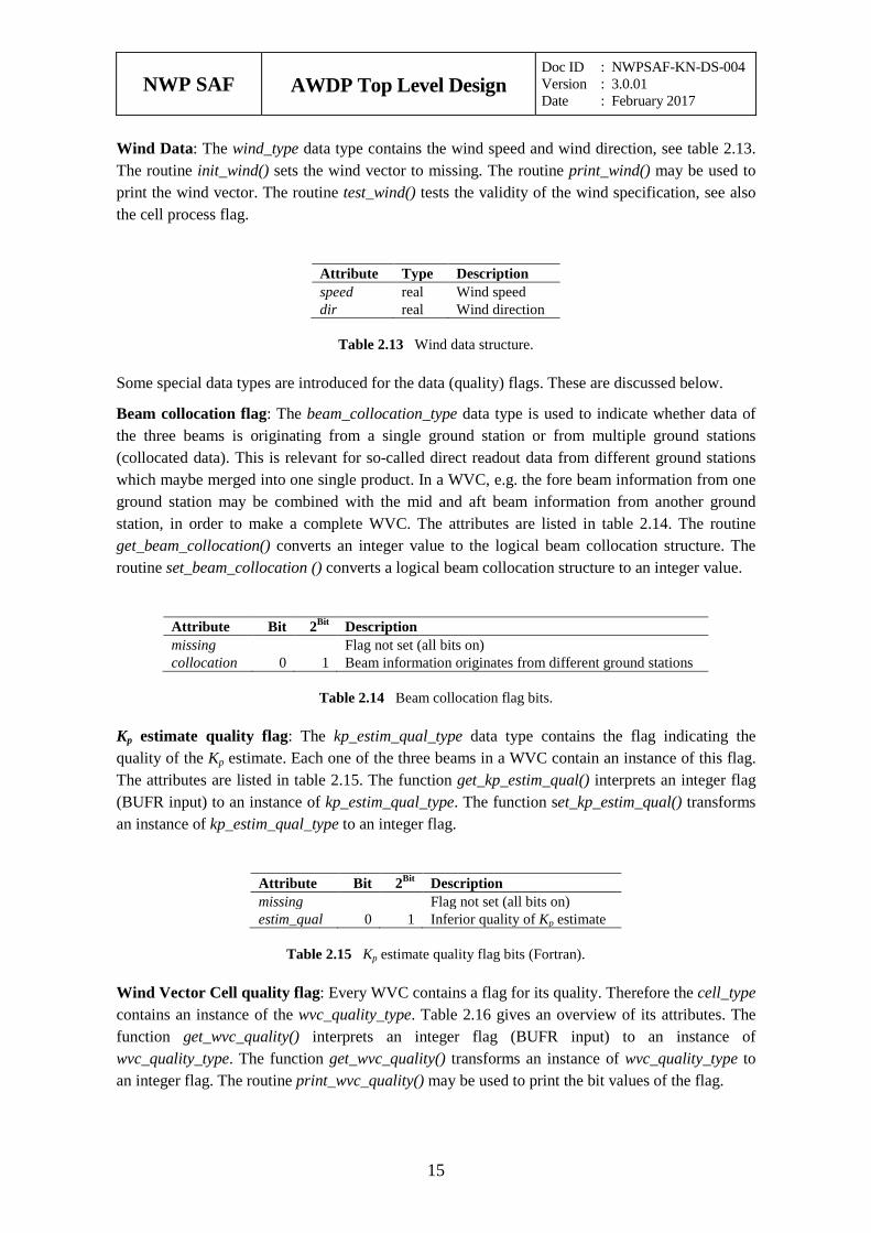
Wind Data: The wind_type data type contains the wind speed and wind direction, see table 2.13. The routine init_wind() sets the wind vector to missing. The routine print_wind() may be used to print the wind vector. The routine test_wind() tests the validity of the wind specification, see also the cell process flag.
Attribute Type Description speed real Wind speed dir real Wind direction
Table 2.13 Wind data structure.
Some special data types are introduced for the data (quality) flags. These are discussed below.
Beam collocation flag: The beam_collocation_type data type is used to indicate whether data of the three beams is originating from a single ground station or from multiple ground stations (collocated data). This is relevant for so-called direct readout data from different ground stations which maybe merged into one single product. In a WVC, e.g. the fore beam information from one ground station may be combined with the mid and aft beam information from another ground station, in order to make a complete WVC. The attributes are listed in table 2.14. The routine get_beam_collocation() converts an integer value to the logical beam collocation structure. The routine set_beam_collocation () converts a logical beam collocation structure to an integer value.
Attribute Bit 2Bit Description missing Flag not set (all bits on) collocation 0 1 Beam information originates from different ground stations
Table 2.14 Beam collocation flag bits.
Kp estimate quality flag: The kp_estim_qual_type data type contains the flag indicating the quality of the Kp estimate. Each one of the three beams in a WVC contain an instance of this flag. The attributes are listed in table 2.15. The function get_kp_estim_qual() interprets an integer flag (BUFR input) to an instance of kp_estim_qual_type. The function set_kp_estim_qual() transforms an instance of kp_estim_qual_type to an integer flag.
Attribute Bit 2Bit Description missing Flag not set (all bits on) estim_qual 0 1 Inferior quality of Kp estimate
Table 2.15 Kp estimate quality flag bits (Fortran).
Wind Vector Cell quality flag: Every WVC contains a flag for its quality. Therefore the cell_type contains an instance of the wvc_quality_type. Table 2.16 gives an overview of its attributes. The function get_wvc_quality() interprets an integer flag (BUFR input) to an instance of wvc_quality_type. The function get_wvc_quality() transforms an instance of wvc_quality_type to an integer flag. The routine print_wvc_quality() may be used to print the bit values of the flag.
NWP SAF
AWDP Top Level Design Doc ID : NWPSAF-KN-DS-004 Version : 3.0.01 Date : February 2017
16
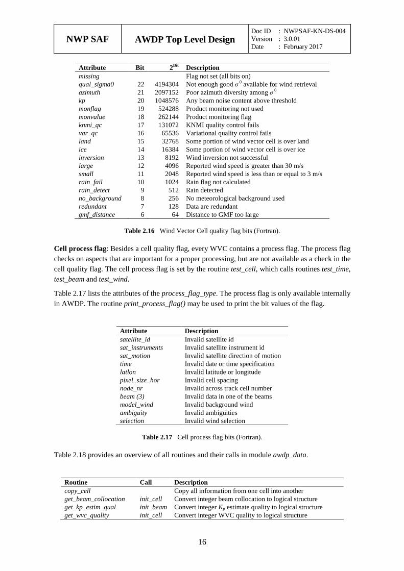
Attribute Bit 2Bit Description missing Flag not set (all bits on) qual_sigma0 22 4194304 Not enough good σ 0 available for wind retrieval azimuth 21 2097152 Poor azimuth diversity among σ 0 kp 20 1048576 Any beam noise content above threshold monflag 19 524288 Product monitoring not used monvalue 18 262144 Product monitoring flag knmi_qc 17 131072 KNMI quality control fails var_qc 16 65536 Variational quality control fails land 15 32768 Some portion of wind vector cell is over land ice 14 16384 Some portion of wind vector cell is over ice inversion 13 8192 Wind inversion not successful large 12 4096 Reported wind speed is greater than 30 m/s small 11 2048 Reported wind speed is less than or equal to 3 m/s rain_fail 10 1024 Rain flag not calculated rain_detect 9 512 Rain detected no_background 8 256 No meteorological background used redundant 7 128 Data are redundant gmf_distance 6 64 Distance to GMF too large
Table 2.16 Wind Vector Cell quality flag bits (Fortran).
Cell process flag: Besides a cell quality flag, every WVC contains a process flag. The process flag checks on aspects that are important for a proper processing, but are not available as a check in the cell quality flag. The cell process flag is set by the routine test_cell, which calls routines test_time, test_beam and test_wind.
Table 2.17 lists the attributes of the process_flag_type. The process flag is only available internally in AWDP. The routine print_process_flag() may be used to print the bit values of the flag.
Attribute Description satellite_id Invalid satellite id sat_instruments Invalid satellite instrument id sat_motion Invalid satellite direction of motion time Invalid date or time specification latlon Invalid latitude or longitude pixel_size_hor Invalid cell spacing node_nr Invalid across track cell number beam (3) Invalid data in one of the beams model_wind Invalid background wind ambiguity Invalid ambiguities selection Invalid wind selection
Table 2.17 Cell process flag bits (Fortran).
Table 2.18 provides an overview of all routines and their calls in module awdp_data.
Routine Call Description copy_cell Copy all information from one cell into another get_beam_collocation init_cell Convert integer beam collocation to logical structure get_kp_estim_qual init_beam Convert integer Kp estimate quality to logical structure get_wvc_quality init_cell Convert integer WVC quality to logical structure
NWP SAF
AWDP Top Level Design Doc ID : NWPSAF-KN-DS-004 Version : 3.0.01 Date : February 2017
17
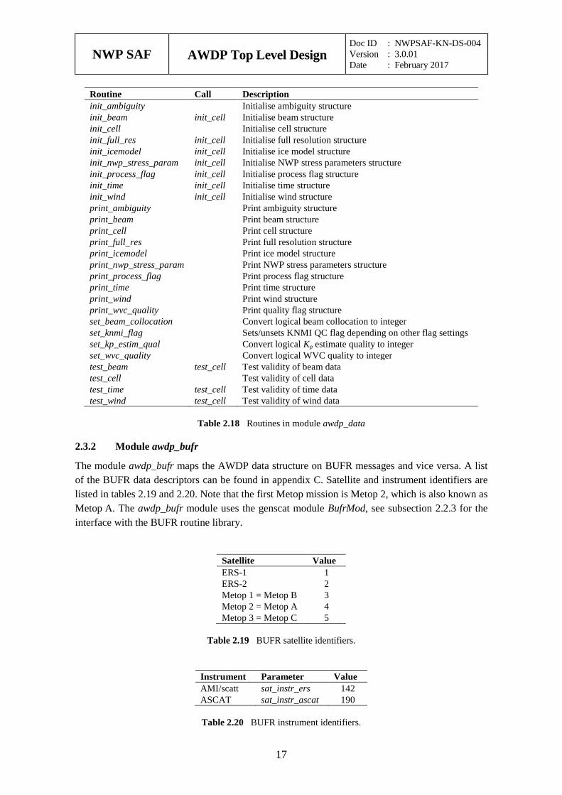
Routine Call Description init_ambiguity Initialise ambiguity structure init_beam init_cell Initialise beam structure init_cell Initialise cell structure init_full_res init_cell Initialise full resolution structure init_icemodel init_cell Initialise ice model structure init_nwp_stress_param init_cell Initialise NWP stress parameters structure init_process_flag init_cell Initialise process flag structure init_time init_cell Initialise time structure init_wind init_cell Initialise wind structure print_ambiguity Print ambiguity structure print_beam Print beam structure print_cell Print cell structure print_full_res Print full resolution structure print_icemodel Print ice model structure print_nwp_stress_param Print NWP stress parameters structure print_process_flag Print process flag structure print_time Print time structure print_wind Print wind structure print_wvc_quality Print quality flag structure set_beam_collocation Convert logical beam collocation to integer set_knmi_flag Sets/unsets KNMI QC flag depending on other flag settings set_kp_estim_qual Convert logical Kp estimate quality to integer set_wvc_quality Convert logical WVC quality to integer test_beam test_cell Test validity of beam data test_cell Test validity of cell data test_time test_cell Test validity of time data test_wind test_cell Test validity of wind data
Table 2.18 Routines in module awdp_data
Module awdp_bufr 2.3.2
The module awdp_bufr maps the AWDP data structure on BUFR messages and vice versa. A list of the BUFR data descriptors can be found in appendix C. Satellite and instrument identifiers are listed in tables 2.19 and 2.20. Note that the first Metop mission is Metop 2, which is also known as Metop A. The awdp_bufr module uses the genscat module BufrMod, see subsection 2.2.3 for the interface with the BUFR routine library.
Satellite Value ERS-1 1 ERS-2 2 Metop 1 = Metop B 3 Metop 2 = Metop A 4 Metop 3 = Metop C 5
Table 2.19 BUFR satellite identifiers.
Instrument Parameter Value AMI/scatt sat_instr_ers 142 ASCAT sat_instr_ascat 190
Table 2.20 BUFR instrument identifiers.
NWP SAF
AWDP Top Level Design Doc ID : NWPSAF-KN-DS-004 Version : 3.0.01 Date : February 2017
18
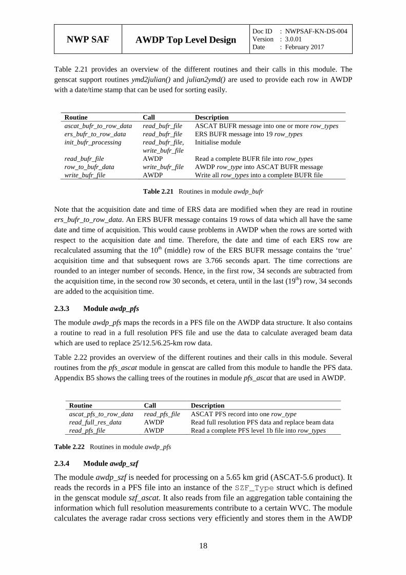
Table 2.21 provides an overview of the different routines and their calls in this module. The genscat support routines ymd2julian() and julian2ymd() are used to provide each row in AWDP with a date/time stamp that can be used for sorting easily.
Routine Call Description ascat_bufr_to_row_data read_bufr_file ASCAT BUFR message into one or more row_types ers_bufr_to_row_data read_bufr_file ERS BUFR message into 19 row_types init_bufr_processing read_bufr_file,
write_bufr_file Initialise module
read_bufr_file AWDP Read a complete BUFR file into row_types row_to_bufr_data write_bufr_file AWDP row_type into ASCAT BUFR message write_bufr_file AWDP Write all row_types into a complete BUFR file
Table 2.21 Routines in module awdp_bufr
Note that the acquisition date and time of ERS data are modified when they are read in routine ers_bufr_to_row_data. An ERS BUFR message contains 19 rows of data which all have the same date and time of acquisition. This would cause problems in AWDP when the rows are sorted with respect to the acquisition date and time. Therefore, the date and time of each ERS row are recalculated assuming that the 10th (middle) row of the ERS BUFR message contains the ‘true’ acquisition time and that subsequent rows are 3.766 seconds apart. The time corrections are rounded to an integer number of seconds. Hence, in the first row, 34 seconds are subtracted from the acquisition time, in the second row 30 seconds, et cetera, until in the last (19th) row, 34 seconds are added to the acquisition time.
Module awdp_pfs 2.3.3
The module awdp_pfs maps the records in a PFS file on the AWDP data structure. It also contains a routine to read in a full resolution PFS file and use the data to calculate averaged beam data which are used to replace 25/12.5/6.25-km row data.
Table 2.22 provides an overview of the different routines and their calls in this module. Several routines from the pfs_ascat module in genscat are called from this module to handle the PFS data. Appendix B5 shows the calling trees of the routines in module pfs_ascat that are used in AWDP.
Routine Call Description ascat_pfs_to_row_data read_pfs_file ASCAT PFS record into one row_type read_full_res_data AWDP Read full resolution PFS data and replace beam data read_pfs_file AWDP Read a complete PFS level 1b file into row_types
Table 2.22 Routines in module awdp_pfs
Module awdp_szf 2.3.4
The module awdp_szf is needed for processing on a 5.65 km grid (ASCAT-5.6 product). It reads the records in a PFS file into an instance of the SZF_Type struct which is defined in the genscat module szf_ascat. It also reads from file an aggregation table containing the information which full resolution measurements contribute to a certain WVC. The module calculates the average radar cross sections very efficiently and stores them in the AWDP
NWP SAF
AWDP Top Level Design Doc ID : NWPSAF-KN-DS-004 Version : 3.0.01 Date : February 2017
19
data structure.
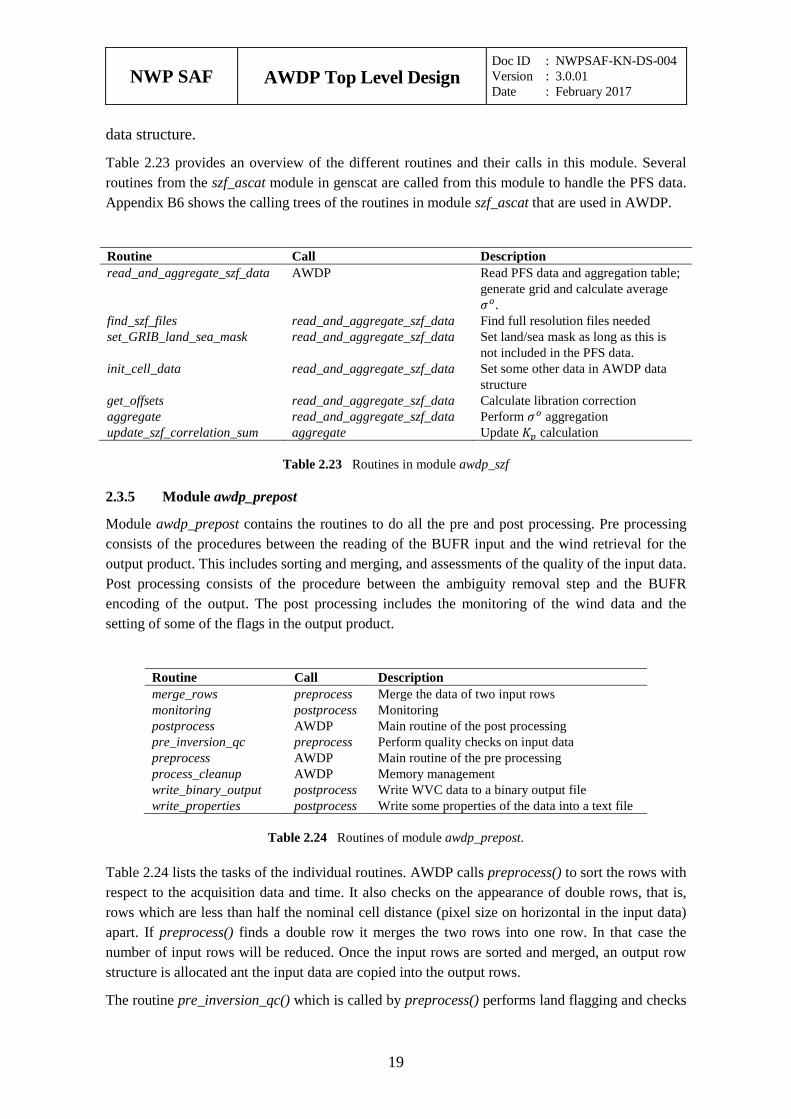
Table 2.23 provides an overview of the different routines and their calls in this module. Several routines from the szf_ascat module in genscat are called from this module to handle the PFS data. Appendix B6 shows the calling trees of the routines in module szf_ascat that are used in AWDP.
Routine Call Description read_and_aggregate_szf_data AWDP Read PFS data and aggregation table;
generate grid and calculate average 𝜎𝜎𝑜𝑜.
find_szf_files read_and_aggregate_szf_data Find full resolution files needed set_GRIB_land_sea_mask read_and_aggregate_szf_data Set land/sea mask as long as this is
not included in the PFS data. init_cell_data read_and_aggregate_szf_data Set some other data in AWDP data
structure get_offsets read_and_aggregate_szf_data Calculate libration correction aggregate read_and_aggregate_szf_data Perform 𝜎𝜎𝑜𝑜 aggregation update_szf_correlation_sum aggregate Update 𝐾𝐾𝑝𝑝 calculation
Table 2.23 Routines in module awdp_szf
Module awdp_prepost 2.3.5
Module awdp_prepost contains the routines to do all the pre and post processing. Pre processing consists of the procedures between the reading of the BUFR input and the wind retrieval for the output product. This includes sorting and merging, and assessments of the quality of the input data. Post processing consists of the procedure between the ambiguity removal step and the BUFR encoding of the output. The post processing includes the monitoring of the wind data and the setting of some of the flags in the output product.
Routine Call Description merge_rows preprocess Merge the data of two input rows monitoring postprocess Monitoring postprocess AWDP Main routine of the post processing pre_inversion_qc preprocess Perform quality checks on input data preprocess AWDP Main routine of the pre processing process_cleanup AWDP Memory management write_binary_output postprocess Write WVC data to a binary output file write_properties postprocess Write some properties of the data into a text file
Table 2.24 Routines of module awdp_prepost.
Table 2.24 lists the tasks of the individual routines. AWDP calls preprocess() to sort the rows with respect to the acquisition data and time. It also checks on the appearance of double rows, that is, rows which are less than half the nominal cell distance (pixel size on horizontal in the input data) apart. If preprocess() finds a double row it merges the two rows into one row. In that case the number of input rows will be reduced. Once the input rows are sorted and merged, an output row structure is allocated ant the input data are copied into the output rows.
The routine pre_inversion_qc() which is called by preprocess() performs land flagging and checks
NWP SAF
AWDP Top Level Design Doc ID : NWPSAF-KN-DS-004 Version : 3.0.01 Date : February 2017
20
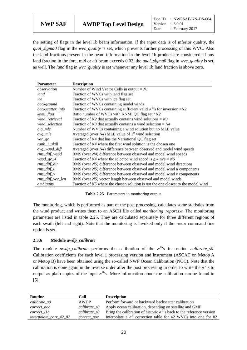
the setting of flags in the level 1b beam information. If the input data is of inferior quality, the qual_sigma0 flag in the wvc_quality is set, which prevents further processing of this WVC. Also the land fractions present in the beam information in the level 1b product are considered: if any land fraction in the fore, mid or aft beam exceeds 0.02, the qual_sigma0 flag in wvc_quality is set, as well. The land flag in wvc_quality is set whenever any level 1b land fraction is above zero.
Parameter Description observation Number of Wind Vector Cells in output = N1 land Fraction of WVCs with land flag set ice Fraction of WVCs with ice flag set background Fraction of WVCs containing model winds backscatter_info Fraction of WVCs containing sufficient valid σ 0’s for inversion =N2 knmi_flag Ratio number of WVCs with KNMI QC flag set / N2 wind_retrieval Fraction of N2 that actually contains wind solutions = N3 wind_selection Fraction of N3 that actually contains a wind selection = N4 big_mle Number of WVCs containing a wind solution but no MLE value avg_mle Averaged (over N4) MLE value of 1st wind selection var_qc Fraction of N4 that has the Variational QC flag set rank_1_skill Fraction of N4 where the first wind solution is the chosen one avg_wspd_diff Averaged (over N4) difference between observed and model wind speeds rms_diff_wspd RMS (over N4) difference between observed and model wind speeds wspd_ge_4 Fraction of N4 where the selected wind speed is ≥ 4 m/s = N5 rms_diff_dir RMS (over N5) difference between observed and model wind directions rms_diff_u RMS (over N5) difference between observed and model wind u components rms_diff_v RMS (over N5) difference between observed and model wind v components rms_diff_vec_len RMS (over N5) vector length between observed and model winds ambiguity Fraction of N5 where the chosen solution is not the one closest to the model wind
Table 2.25 Parameters in monitoring output.
The monitoring, which is performed as part of the post processing, calculates some statistics from the wind product and writes them to an ASCII file called monitoring_report.txt. The monitoring parameters are listed in table 2.25. They are calculated separately for three different regions of each swath (left and right). Note that the monitoring is invoked only if the –mon command line option is set.
Module awdp_calibrate 2.3.6
The module awdp_calibrate performs the calibration of the σ 0’s in routine calibrate_s0. Calibration coefficients for each level 1 processing version and instrument (ASCAT on Metop A or Metop B) have been obtained using the so-called NWP Ocean Calibration (NOC). Note that the calibration is done again in the reverse order after the post processing in order to write the σ 0’s to output as plain copies of the input σ 0’s. More information about the calibration can be found in [5].
Routine Call Description calibrate_s0 AWDP Perform forward or backward backscatter calibration correct_noc calibrate_s0 Apply ocean calibration, depending on satellite and GMF correct_l1b calibrate_s0 Bring the calibration of historic σ 0’s back to the reference version interpolate_corr_42_82 correct_noc Interpolate a σ 0 correction table for 42 WVCs into one for 82
NWP SAF
AWDP Top Level Design Doc ID : NWPSAF-KN-DS-004 Version : 3.0.01 Date : February 2017
21
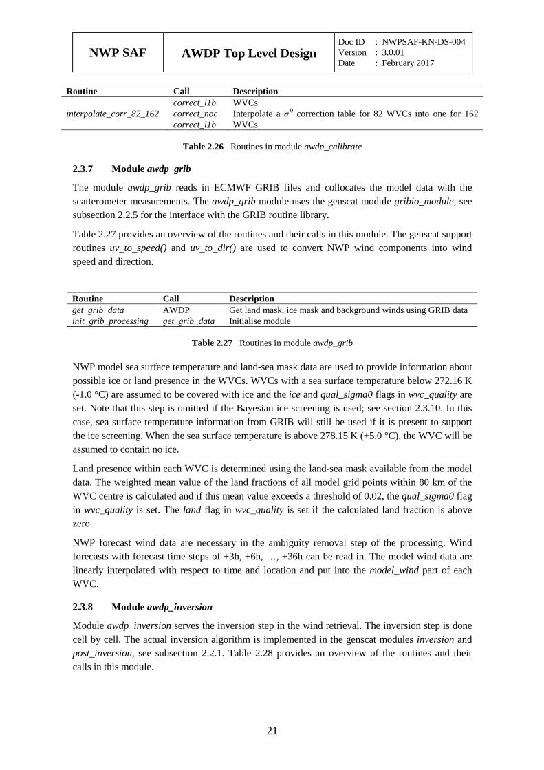
Routine Call Description correct_l1b WVCs
interpolate_corr_82_162 correct_noc correct_l1b
Interpolate a σ 0 correction table for 82 WVCs into one for 162 WVCs
Table 2.26 Routines in module awdp_calibrate
Module awdp_grib 2.3.7
The module awdp_grib reads in ECMWF GRIB files and collocates the model data with the scatterometer measurements. The awdp_grib module uses the genscat module gribio_module, see subsection 2.2.5 for the interface with the GRIB routine library.
Table 2.27 provides an overview of the routines and their calls in this module. The genscat support routines uv_to_speed() and uv_to_dir() are used to convert NWP wind components into wind speed and direction.
Routine Call Description get_grib_data AWDP Get land mask, ice mask and background winds using GRIB data init_grib_processing get_grib_data Initialise module
Table 2.27 Routines in module awdp_grib
NWP model sea surface temperature and land-sea mask data are used to provide information about possible ice or land presence in the WVCs. WVCs with a sea surface temperature below 272.16 K (-1.0 °C) are assumed to be covered with ice and the ice and qual_sigma0 flags in wvc_quality are set. Note that this step is omitted if the Bayesian ice screening is used; see section 2.3.10. In this case, sea surface temperature information from GRIB will still be used if it is present to support the ice screening. When the sea surface temperature is above 278.15 K (+5.0 °C), the WVC will be assumed to contain no ice.
Land presence within each WVC is determined using the land-sea mask available from the model data. The weighted mean value of the land fractions of all model grid points within 80 km of the WVC centre is calculated and if this mean value exceeds a threshold of 0.02, the qual_sigma0 flag in wvc_quality is set. The land flag in wvc_quality is set if the calculated land fraction is above zero.
NWP forecast wind data are necessary in the ambiguity removal step of the processing. Wind forecasts with forecast time steps of +3h, +6h, …, +36h can be read in. The model wind data are linearly interpolated with respect to time and location and put into the model_wind part of each WVC.
Module awdp_inversion 2.3.8
Module awdp_inversion serves the inversion step in the wind retrieval. The inversion step is done cell by cell. The actual inversion algorithm is implemented in the genscat modules inversion and post_inversion, see subsection 2.2.1. Table 2.28 provides an overview of the routines and their calls in this module.
NWP SAF
AWDP Top Level Design Doc ID : NWPSAF-KN-DS-004 Version : 3.0.01 Date : February 2017
22
Routine Call Description init_inversion invert_wvcs Initialisation invert_node invert_wvcs Call to the genscat inversion routines invert_wvcs AWDP Loop over all WVCs and perform inversion
Table 2.28 Routines of module awdp_inversion.
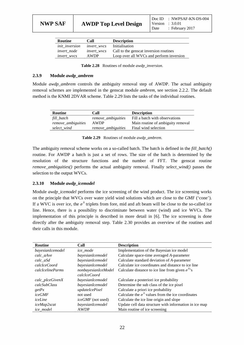
Module awdp_ambrem 2.3.9
Module awdp_ambrem controls the ambiguity removal step of AWDP. The actual ambiguity removal schemes are implemented in the genscat module ambrem, see section 2.2.2. The default method is the KNMI 2DVAR scheme. Table 2.29 lists the tasks of the individual routines.
Routine Call Description fill_batch remove_ambiguities Fill a batch with observations remove_ambiguities AWDP Main routine of ambiguity removal select_wind remove_ambiguities Final wind selection
Table 2.29 Routines of module awdp_ambrem.
The ambiguity removal scheme works on a so-called batch. The batch is defined in the fill_batch() routine. For AWDP a batch is just a set of rows. The size of the batch is determined by the resolution of the structure functions and the number of FFT. The genscat routine remove_ambiguities() performs the actual ambiguity removal. Finally select_wind() passes the selection to the output WVCs.
Module awdp_icemodel 2.3.10
Module awdp_icemodel performs the ice screening of the wind product. The ice screening works on the principle that WVCs over water yield wind solutions which are close to the GMF (‘cone’). If a WVC is over ice, the σ 0 triplets from fore, mid and aft beam will be close to the so-called ice line. Hence, there is a possibility to discriminate between water (wind) and ice WVCs. The implementation of this principle is described in more detail in [6]. The ice screening is done directly after the ambiguity removal step. Table 2.30 provides an overview of the routines and their calls in this module.
Routine Call Description bayesianIcemodel ice_mode Implementation of the Bayesian ice model calc_aAve bayesianIcemodel Calculate space-time averaged A-parameter calc_aSd bayesianIcemodel Calculate standard deviation of A-parameter calcIceCoord bayesianIcemodel Calculate ice coordinates and distance to ice line calcIcelineParms nonbayesianIceModel
calcIceCoord Calculate distance to ice line from given σ 0’s
calc_pIceGivenX bayesianIcemodel Calculate a posteriori ice probability calcSubClass bayesianIcemodel Determine the sub class of the ice pixel getPx updateIcePixel Calculate a priori ice probability iceGMF not used Calculate the σ 0 values from the ice coordinates iceLine iceGMF (not used) Calculate the ice line origin and slope iceMap2scat bayesianIcemodel Update cell data structure with information in ice map ice_model AWDP Main routine of ice screening
NWP SAF
AWDP Top Level Design Doc ID : NWPSAF-KN-DS-004 Version : 3.0.01 Date : February 2017
23
Routine Call Description nonbayesianIceModel ice_mode Implementation of the basic ice model without history scat2iceMap bayesianIcemodel Update the ice map with the information in cell data setCmix bayesianIcemodel Compute geophysical ice model tolerance parameter smooth bayesianIcemodel Spatial smoothing of the a posteriori probability updateIcePixel scat2iceMap Update one ice pixel
Table 2.30 Routines of module awdp_icemodel.
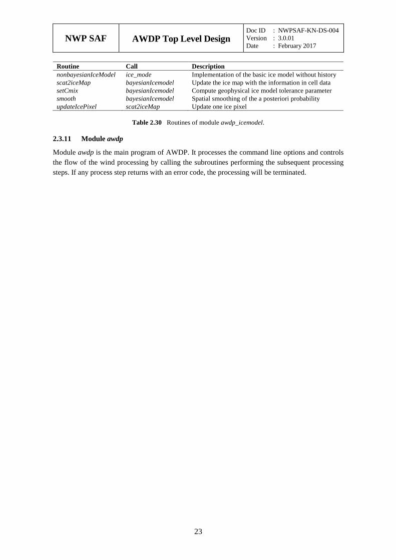
Module awdp 2.3.11
Module awdp is the main program of AWDP. It processes the command line options and controls the flow of the wind processing by calling the subroutines performing the subsequent processing steps. If any process step returns with an error code, the processing will be terminated.
NWP SAF
AWDP Top Level Design Doc ID : NWPSAF-KN-DS-004 Version : 3.0.01 Date : February 2017
24
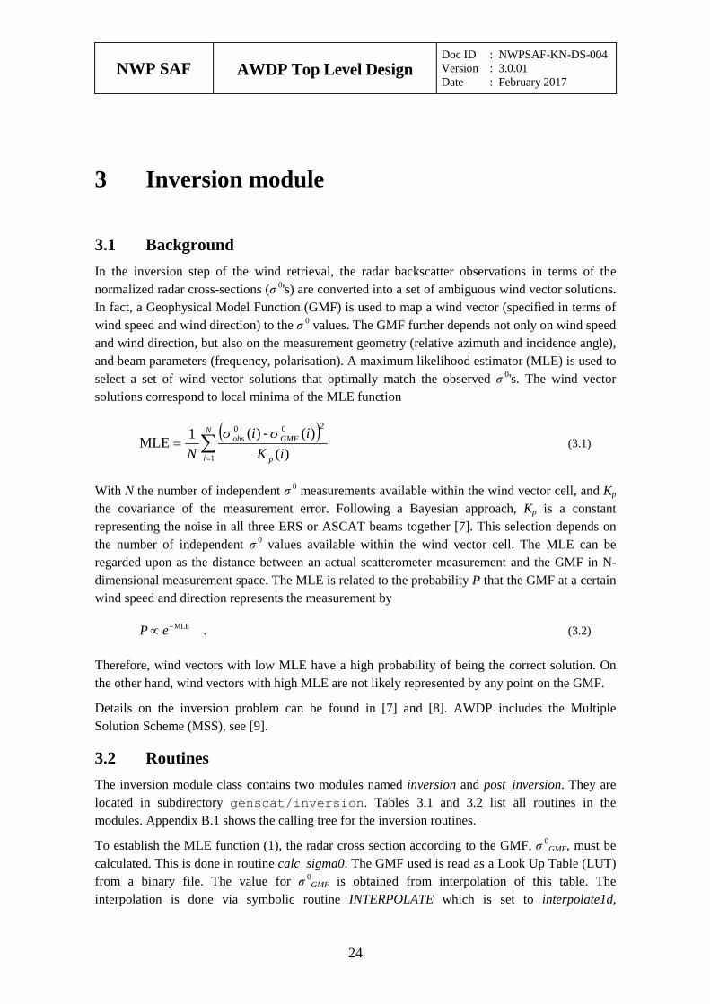
Inversion module 3
3.1 Background In the inversion step of the wind retrieval, the radar backscatter observations in terms of the normalized radar cross-sections (σ 0's) are converted into a set of ambiguous wind vector solutions. In fact, a Geophysical Model Function (GMF) is used to map a wind vector (specified in terms of wind speed and wind direction) to the σ 0 values. The GMF further depends not only on wind speed and wind direction, but also on the measurement geometry (relative azimuth and incidence angle), and beam parameters (frequency, polarisation). A maximum likelihood estimator (MLE) is used to select a set of wind vector solutions that optimally match the observed σ 0's. The wind vector solutions correspond to local minima of the MLE function
( )∑=
=N
i p
GMFobs
iKii
N 1
200
)()(-)(1MLE
ss (3.1)
With N the number of independent σ 0 measurements available within the wind vector cell, and Kp the covariance of the measurement error. Following a Bayesian approach, Kp is a constant representing the noise in all three ERS or ASCAT beams together [7]. This selection depends on the number of independent σ 0 values available within the wind vector cell. The MLE can be regarded upon as the distance between an actual scatterometer measurement and the GMF in N-dimensional measurement space. The MLE is related to the probability P that the GMF at a certain wind speed and direction represents the measurement by
.MLE−∝ eP (3.2)
Therefore, wind vectors with low MLE have a high probability of being the correct solution. On the other hand, wind vectors with high MLE are not likely represented by any point on the GMF.
Details on the inversion problem can be found in [7] and [8]. AWDP includes the Multiple Solution Scheme (MSS), see [9].
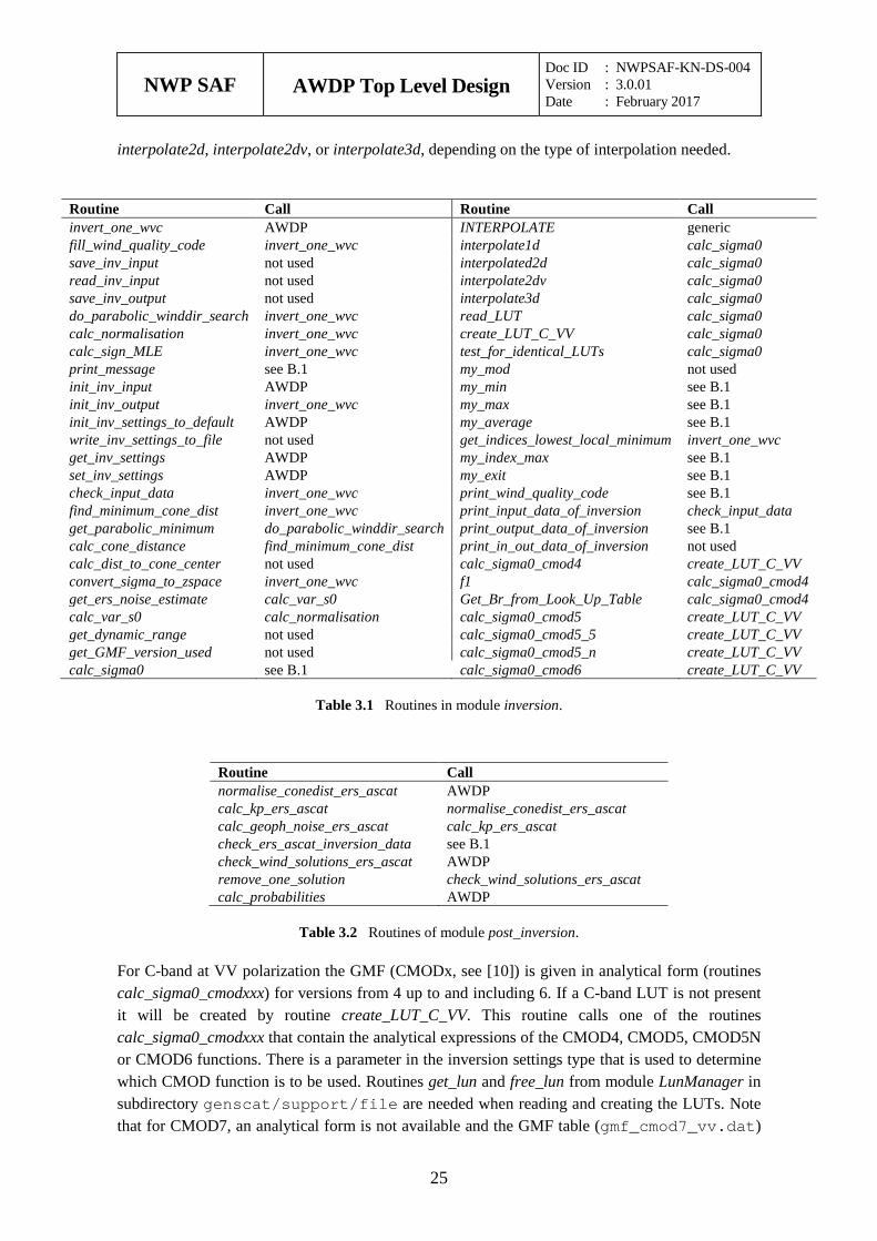
3.2 Routines The inversion module class contains two modules named inversion and post_inversion. They are located in subdirectory genscat/inversion. Tables 3.1 and 3.2 list all routines in the modules. Appendix B.1 shows the calling tree for the inversion routines.
To establish the MLE function (1), the radar cross section according to the GMF, σ 0GMF, must be
calculated. This is done in routine calc_sigma0. The GMF used is read as a Look Up Table (LUT) from a binary file. The value for σ 0
GMF is obtained from interpolation of this table. The interpolation is done via symbolic routine INTERPOLATE which is set to interpolate1d,
NWP SAF
AWDP Top Level Design Doc ID : NWPSAF-KN-DS-004 Version : 3.0.01 Date : February 2017
25
interpolate2d, interpolate2dv, or interpolate3d, depending on the type of interpolation needed.
Routine Call Routine Call invert_one_wvc AWDP INTERPOLATE generic fill_wind_quality_code invert_one_wvc interpolate1d calc_sigma0 save_inv_input not used interpolated2d calc_sigma0 read_inv_input not used interpolate2dv calc_sigma0 save_inv_output not used interpolate3d calc_sigma0 do_parabolic_winddir_search invert_one_wvc read_LUT calc_sigma0 calc_normalisation invert_one_wvc create_LUT_C_VV calc_sigma0 calc_sign_MLE invert_one_wvc test_for_identical_LUTs calc_sigma0 print_message see B.1 my_mod not used init_inv_input AWDP my_min see B.1 init_inv_output invert_one_wvc my_max see B.1 init_inv_settings_to_default AWDP my_average see B.1 write_inv_settings_to_file not used get_indices_lowest_local_minimum invert_one_wvc get_inv_settings AWDP my_index_max see B.1 set_inv_settings AWDP my_exit see B.1 check_input_data invert_one_wvc print_wind_quality_code see B.1 find_minimum_cone_dist invert_one_wvc print_input_data_of_inversion check_input_data get_parabolic_minimum do_parabolic_winddir_search print_output_data_of_inversion see B.1 calc_cone_distance find_minimum_cone_dist print_in_out_data_of_inversion not used calc_dist_to_cone_center not used calc_sigma0_cmod4 create_LUT_C_VV convert_sigma_to_zspace invert_one_wvc f1 calc_sigma0_cmod4 get_ers_noise_estimate calc_var_s0 Get_Br_from_Look_Up_Table calc_sigma0_cmod4 calc_var_s0 calc_normalisation calc_sigma0_cmod5 create_LUT_C_VV get_dynamic_range not used calc_sigma0_cmod5_5 create_LUT_C_VV get_GMF_version_used not used calc_sigma0_cmod5_n create_LUT_C_VV calc_sigma0 see B.1 calc_sigma0_cmod6 create_LUT_C_VV
Table 3.1 Routines in module inversion.
Routine Call normalise_conedist_ers_ascat AWDP calc_kp_ers_ascat normalise_conedist_ers_ascat calc_geoph_noise_ers_ascat calc_kp_ers_ascat check_ers_ascat_inversion_data see B.1 check_wind_solutions_ers_ascat AWDP remove_one_solution check_wind_solutions_ers_ascat calc_probabilities AWDP
Table 3.2 Routines of module post_inversion.
For C-band at VV polarization the GMF (CMODx, see [10]) is given in analytical form (routines calc_sigma0_cmodxxx) for versions from 4 up to and including 6. If a C-band LUT is not present it will be created by routine create_LUT_C_VV. This routine calls one of the routines calc_sigma0_cmodxxx that contain the analytical expressions of the CMOD4, CMOD5, CMOD5N or CMOD6 functions. There is a parameter in the inversion settings type that is used to determine which CMOD function is to be used. Routines get_lun and free_lun from module LunManager in subdirectory genscat/support/file are needed when reading and creating the LUTs. Note that for CMOD7, an analytical form is not available and the GMF table (gmf_cmod7_vv.dat)
NWP SAF
AWDP Top Level Design Doc ID : NWPSAF-KN-DS-004 Version : 3.0.01 Date : February 2017
26
needs to be read from awdp/data/little_endian or awdp/data/big_endian.
Note that module post_inversion uses some tables for the normalisation of MLEs and noise values. These tables are read from ASCII files which are present in direction genscat/inversion. The environment variable $INVERSION_LUTSDIR should contain the proper directory name.
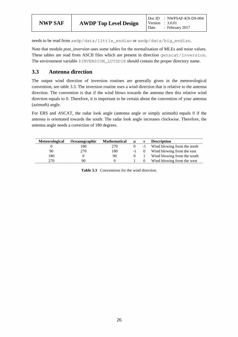
3.3 Antenna direction The output wind direction of inversion routines are generally given in the meteorological convention, see table 3.3. The inversion routine uses a wind direction that is relative to the antenna direction. The convention is that if the wind blows towards the antenna then this relative wind direction equals to 0. Therefore, it is important to be certain about the convention of your antenna (azimuth) angle.
For ERS and ASCAT, the radar look angle (antenna angle or simply azimuth) equals 0 if the antenna is orientated towards the south. The radar look angle increases clockwise. Therefore, the antenna angle needs a correction of 180 degrees.
Meteorological Oceanographic Mathematical u v Description 0 180 270 0 -1 Wind blowing from the north
90 270 180 -1 0 Wind blowing from the east 180 0 90 0 1 Wind blowing from the south 270 90 0 1 0 Wind blowing from the west
Table 3.3 Conventions for the wind direction.
NWP SAF
AWDP Top Level Design Doc ID : NWPSAF-KN-DS-004 Version : 3.0.01 Date : February 2017
27
Ambiguity Removal module 4
4.1 Ambiguity Removal Ambiguity Removal (AR) schemes select a surface wind vector among the different surface wind vector solutions per cell for the set of wind vector cells in consideration. The goal is to set a unique, meteorological consistent surface wind field. The surface wind vector solutions per cell, simply called ambiguities, result from the wind retrieval process step.
Whenever the ambiguities are ranked, a naive scheme would be to select the ambiguity with the first rank (e.g., the highest probability, the lowest distance to the wind cone). In general, such a persistent first rank selection will not suffice to create a realistic surface wind vector field: scatterometer measurements tend to generate ambiguous wind solutions with approximately equal likelihood (mainly due to the ~180° invariance of stand alone scatterometer measurements). Therefore one needs additional spatial constraints and/or additional (external) information in order to make sensible selections.
A common way to add external information to a WVC is to provide a background surface wind vector. The background wind acts as a first approximation for the expected mean wind over the cell. In general, a NWP model wind is interpolated for this purpose. Whenever a background wind is set for the WVC, a second naive Ambiguity Removal scheme is at hand: the Background Closest (BC) scheme. The selected wind vector is just the minimizer of the distance (e.g., in the least squares sense) to the background wind vector. This scheme may produce far more realistic wind vector fields than the first rank selection, since the background surface wind field is meteorologically consistent.
However, background surface winds have their own uncertainty. Therefore, sophisticated schemes for Ambiguity Removal take both the likelihood of the ambiguities and the uncertainty of the background surface wind into account. Examples are the KNMI Two-Dimensional Variational (2DVAR) scheme and the PreScat scheme.
The implementation of these schemes is described in sections 4.4 and 4.5.
4.2 Module ambrem Module Ambrem is the interface module between the various ambiguity removal methods and the different scatterometer data processors. Table 4.1 provides an overview of the different routines and their calls. A dummy method and the first rank selection method are implemented as part of ambrem. More elaborate Ambiguity Removal methods have an interface module, see table 4.2. Figure 4.1 shows schematically the interdependence of the various modules for Ambiguity Removal.

NWP SAF
AWDP Top Level Design Doc ID : NWPSAF-KN-DS-004 Version : 3.0.01 Date : February 2017
28
Routine Call Description InitAmbremModule AWDP Initialization of module Ambrem InitAmbremMethod AWDP Initialization of specified AR scheme DoAmbrem AWDP Execution of specified AR scheme Ambrem1stRank DoAmbrem First rank selection method DoDummyMeth DoAmbrem Dummy AR scheme for testing SetDummyMeth DoAmbrem Batch definition of dummy method InitDummyMeth DoAmbrem Initialization of dummy method InitDummyBatch not used ExitAmbremMethod AWDP Deallocation of memory
Table 4.1 Routines of module Ambrem.
Routine Description Documentation Ambrem2DVAR Interface to KNMI 2DVAR method Section 4.4 AmbremBGClosest Interface to Background Closest method Section 4.1 AmbremPrescat Interface to Prescat method Section 4.5
Table 4.2 Interface modules for different Ambiguity Removal schemes.
Figure 4.1 Interdependence of the modules for Ambiguity Removal. The connections from module ambrem to module BatchMod and from module Ambrem2DVAR to convert are not drawn.
4.3 Module BatchMod After the wind retrieval step, the Ambiguity Removal step is performed on selections of the available data. In general, these selections are just a compact part of the swath or a compact part of
ambrem
Ambrem2DVAR AmbremPreScat AmbremBGclosest
TwoDvar
BatchMod
CostFunction
SingletonFFT BFGSMod TwoDvarData
StrucFunc
convert
NWP SAF
AWDP Top Level Design Doc ID : NWPSAF-KN-DS-004 Version : 3.0.01 Date : February 2017
29
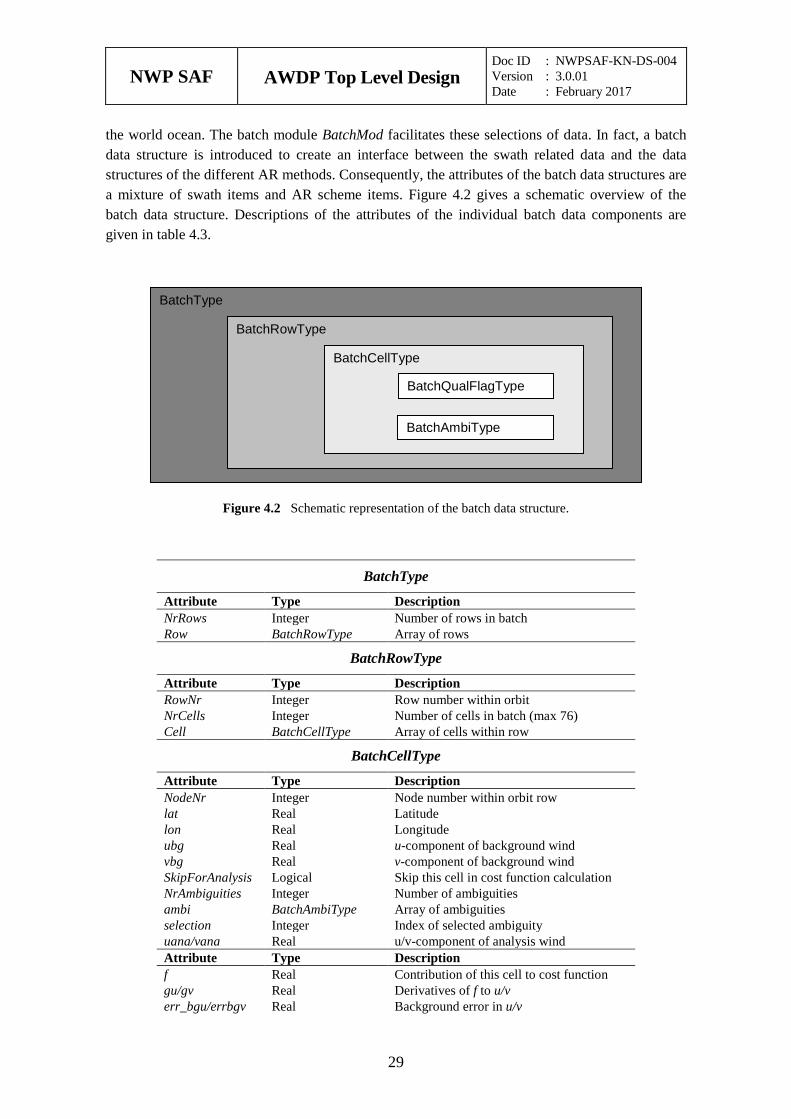
the world ocean. The batch module BatchMod facilitates these selections of data. In fact, a batch data structure is introduced to create an interface between the swath related data and the data structures of the different AR methods. Consequently, the attributes of the batch data structures are a mixture of swath items and AR scheme items. Figure 4.2 gives a schematic overview of the batch data structure. Descriptions of the attributes of the individual batch data components are given in table 4.3.
Figure 4.2 Schematic representation of the batch data structure.
BatchType
Attribute Type Description NrRows Integer Number of rows in batch Row BatchRowType Array of rows
BatchRowType
Attribute Type Description RowNr Integer Row number within orbit NrCells Integer Number of cells in batch (max 76) Cell BatchCellType Array of cells within row
BatchCellType
Attribute Type Description NodeNr Integer Node number within orbit row lat Real Latitude lon Real Longitude ubg Real u-component of background wind vbg Real v-component of background wind SkipForAnalysis Logical Skip this cell in cost function calculation NrAmbiguities Integer Number of ambiguities ambi BatchAmbiType Array of ambiguities selection Integer Index of selected ambiguity uana/vana Real u/v-component of analysis wind Attribute Type Description f Real Contribution of this cell to cost function gu/gv Real Derivatives of f to u/v err_bgu/errbgv Real Background error in u/v
BatchType
BatchRowType
BatchCellType
BatchQualFlagType
BatchAmbiType
NWP SAF
AWDP Top Level Design Doc ID : NWPSAF-KN-DS-004 Version : 3.0.01 Date : February 2017
30
err_obu/err_obv Real Observation error in u/v qualflag BatchQualFlagType Quality control flag
BatchAmbiType
Attribute Type Description u/v Real Analysis increments prob Real A-priori probability
Table 4.3 Batch data structures.
To check the quality of the batch a quality flag is introduced for instances of the BatchCellType. The flag is set by routine TestBatchCell(). The attributes of this flag of type BatchQualFlagType are listed in table 4.4.
Attribute Description Missing Quality flag not set Node Incorrect node number specification Lat Incorrect latitude specification Lon Incorrect longitude specification Ambiguities Invalid ambiguities Selection Invalid selection indicator Background Incorrect background wind specification Analysis Incorrect analysis Threshold Threshold overflow Cost Invalid cost function value Gradient Invalid gradient value
Table 4.4 Batch quality flag attributes.
Routine Call Description AllocRowsAndCellsAndInitBatch Processor Allocation of batch AllocAndInitBatchRow AllocRowsAndCellsAndInitBatch Allocation of batch rows AllocAndInitBatchCell AllocAndInitBatchRow Allocation of batch cells AllocRowsOnlyAndInitBatch not used InitBatchModule Ambrem Initialization module InitBatch AllocRowsAndCellsAndInitBatch Initialization of batch InitBatchRow InitBatch Initialization of batch rows InitBatchCell InitBatchRow Initialization of batch cells InitbatchAmbi InitBatchCell Initialization of batch ambiguities DeallocBatch Processor Deallocation of batch DeallocBatchRows DeallocBatch Deallocation of batch rows DeallocBatchCells DeallocBatchRows Deallocation of batch cells DeallocBatchAmbis DeallocBatchCells Deallocation of batch ambiguities TestBatch Processor Test complete batch TestBatchRow TestBatch Test complete batch row TestBatchCell TestBatchRow Test batch cell TestBatchQualFlag Processor Print the quality flag getBatchQualFlag not used setBatchQualFlag not used PrnBatchQualFlag not used
Table 4.5 Routines of module BatchMod.
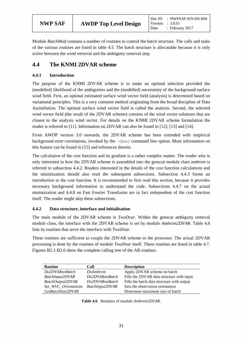
NWP SAF
AWDP Top Level Design Doc ID : NWPSAF-KN-DS-004 Version : 3.0.01 Date : February 2017
31
Module BatchMod contains a number of routines to control the batch structure. The calls and tasks of the various routines are listed in table 4.5. The batch structure is allocatable because it is only active between the wind retrieval and the ambiguity removal step.
4.4 The KNMI 2DVAR scheme
Introduction 4.4.1
The purpose of the KNMI 2DVAR scheme is to make an optimal selection provided the (modelled) likelihood of the ambiguities and the (modelled) uncertainty of the background surface wind field. First, an optimal estimated surface wind vector field (analysis) is determined based on variational principles. This is a very common method originating from the broad discipline of Data Assimilation. The optimal surface wind vector field is called the analysis. Second, the selected wind vector field (the result of the 2DVAR scheme) consists of the wind vector solutions that are closest to the analysis wind vector. For details on the KNMI 2DVAR scheme formulation the reader is referred to [11]. Information on 2DVAR can also be found in [12], [13] and [14].
From AWDP version 3.0 onwards, the 2DVAR scheme has been extended with empirical background error correlations, invoked by the -nbec command line option. More information on this feature can be found in [15] and references therein.
The calculation of the cost function and its gradient is a rather complex matter. The reader who is only interested in how the 2DVAR scheme is assembled into the genscat module class ambrem is referred to subsection 4.4.2. Readers interested in the details of the cost function calculations and the minimization should also read the subsequent subsections. Subsection 4.4.3 forms an introduction to the cost function. It is recommended to first read this section, because it provides necessary background information to understand the code. Subsections 4.4.7 on the actual minimization and 4.4.8 on Fast Fourier Transforms are in fact independent of the cost function itself. The reader might skip these subsections.
Data structure, interface and initialisation 4.4.2
The main module of the 2DVAR scheme is TwoDvar. Within the genscat ambiguity removal module class, the interface with the 2DVAR scheme is set by module Ambrem2DVAR. Table 4.6 lists its routines that serve the interface with TwoDvar.
These routines are sufficient to couple the 2DVAR scheme to the processor. The actual 2DVAR processing is done by the routines of module TwoDvar itself. These routines are listed in table 4.7. Figures B2.1-B2.6 show the complete calling tree of the AR routines.
Routine Call Description Do2DVARonBatch DoAmbrem Apply 2DVAR scheme on batch BatchInput2DVAR Do2DVARonBatch Fills the 2DVAR data structure with input BatchOutput2DVAR Do2DVARonBatch Fills the batch data structure with output Set_WVC_Orientations BatchInput2DVAR Sets the observation orientation GetBatchSize2DVAR Determine maximum size of batch
Table 4.6 Routines of module Ambrem2DVAR.
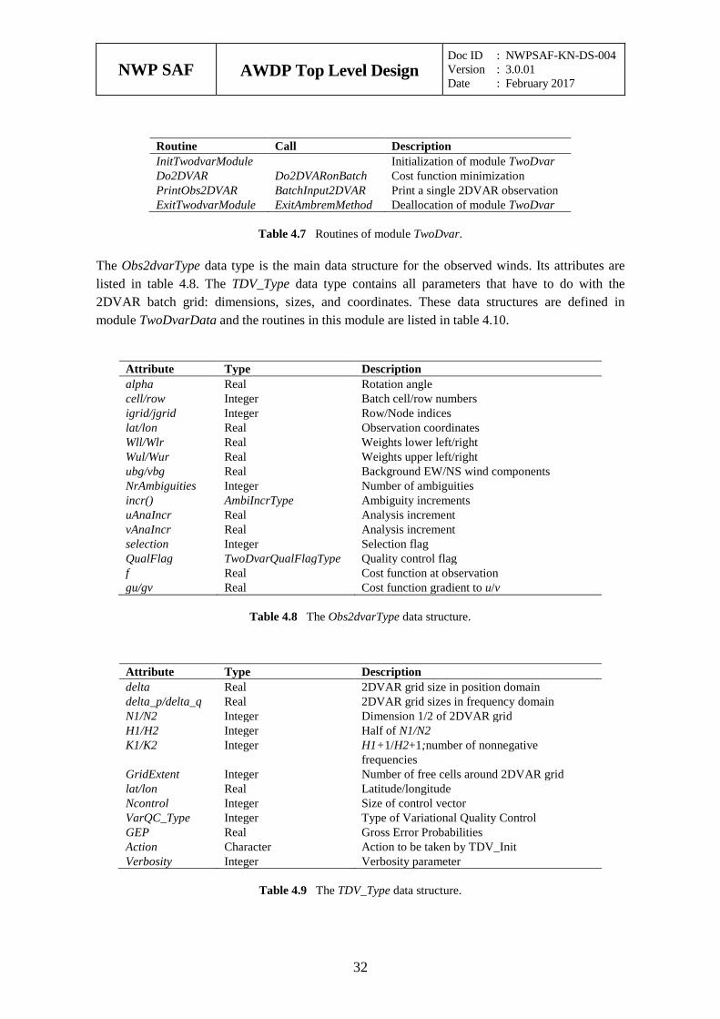
NWP SAF
AWDP Top Level Design Doc ID : NWPSAF-KN-DS-004 Version : 3.0.01 Date : February 2017
32
Routine Call Description InitTwodvarModule Initialization of module TwoDvar Do2DVAR Do2DVARonBatch Cost function minimization PrintObs2DVAR BatchInput2DVAR Print a single 2DVAR observation ExitTwodvarModule ExitAmbremMethod Deallocation of module TwoDvar
Table 4.7 Routines of module TwoDvar.
The Obs2dvarType data type is the main data structure for the observed winds. Its attributes are listed in table 4.8. The TDV_Type data type contains all parameters that have to do with the 2DVAR batch grid: dimensions, sizes, and coordinates. These data structures are defined in module TwoDvarData and the routines in this module are listed in table 4.10.
Attribute Type Description alpha Real Rotation angle cell/row Integer Batch cell/row numbers igrid/jgrid Integer Row/Node indices lat/lon Real Observation coordinates Wll/Wlr Real Weights lower left/right Wul/Wur Real Weights upper left/right ubg/vbg Real Background EW/NS wind components NrAmbiguities Integer Number of ambiguities incr() AmbiIncrType Ambiguity increments uAnaIncr Real Analysis increment vAnaIncr Real Analysis increment selection Integer Selection flag QualFlag TwoDvarQualFlagType Quality control flag f Real Cost function at observation gu/gv Real Cost function gradient to u/v
Table 4.8 The Obs2dvarType data structure.
Attribute Type Description delta Real 2DVAR grid size in position domain delta_p/delta_q Real 2DVAR grid sizes in frequency domain N1/N2 Integer Dimension 1/2 of 2DVAR grid H1/H2 Integer Half of N1/N2 K1/K2 Integer H1+1/H2+1;number of nonnegative
frequencies GridExtent Integer Number of free cells around 2DVAR grid lat/lon Real Latitude/longitude Ncontrol Integer Size of control vector VarQC_Type Integer Type of Variational Quality Control GEP Real Gross Error Probabilities Action Character Action to be taken by TDV_Init Verbosity Integer Verbosity parameter
Table 4.9 The TDV_Type data structure.
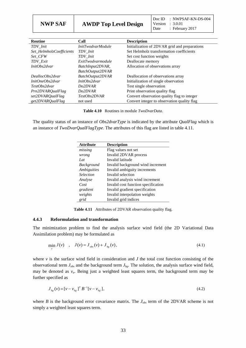
NWP SAF
AWDP Top Level Design Doc ID : NWPSAF-KN-DS-004 Version : 3.0.01 Date : February 2017
33
Routine Call Description TDV_Init InitTwodvarModule Initialization of 2DVAR grid and preparations Set_HelmholzCoefficients TDV_Init Set Helmholz transformation coefficients Set_CFW TDV_Init Set cost function weights TDV_Exit ExitTwodvarmodule Deallocate memory InitObs2dvar BatchInput2DVAR,
BatchOutput2DVAR Allocation of observations array
DeallocObs2dvar BatchOutput2DVAR Deallocation of observations array InitOneObs2dvar InitObs2dvar Initialization of single observation TestObs2dvar Do2DVAR Test single observation Prn2DVARQualFlag Do2DVAR Print observation quality flag set2DVARQualFlag TestObs2DVAR Convert observation quality flag to integer get2DVARQualFlag not used Convert integer to observation quality flag
Table 4.10 Routines in module TwoDvarData.
The quality status of an instance of Obs2dvarType is indicated by the attribute QualFlag which is an instance of TwoDvarQualFlagType. The attributes of this flag are listed in table 4.11.
Attribute Description missing Flag values not set wrong Invalid 2DVAR process Lat Invalid latitude Background Invalid background wind increment Ambiguities Invalid ambiguity increments Selection Invalid selection Analyse Invalid analysis wind increment Cost Invalid cost function specification gradient Invalid gradient specification weights Invalid interpolation weights grid Invalid grid indices
Table 4.11 Attributes of 2DVAR observation quality flag.
Reformulation and transformation 4.4.3
The minimization problem to find the analysis surface wind field (the 2D Variational Data Assimilation problem) may be formulated as
)()()(,)(min vJvJvJvJ bgobsv
+= , (4.1)
where v is the surface wind field in consideration and J the total cost function consisting of the observational term Jobs and the background term Jbg. The solution, the analysis surface wind field, may be denoted as va. Being just a weighted least squares term, the background term may be further specified as
][][)( 1bg
Tbgbg vvBvvvJ −−= − , (4.2)
where B is the background error covariance matrix. The Jobs term of the 2DVAR scheme is not simply a weighted least squares term.
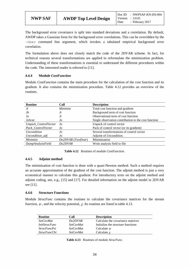
NWP SAF
AWDP Top Level Design Doc ID : NWPSAF-KN-DS-004 Version : 3.0.01 Date : February 2017
34
The background error covariance is split into standard deviations and a correlation. By default, AWDP takes a Gaussian form for the background error correlations. This can be overridden by the -nbec command line argument, which invokes a tabulated empirical background error correlation.
The formulation above does not closely match the code of the 2DVAR scheme. In fact, for technical reasons several transformations are applied to reformulate the minimization problem. Understanding of these transformations is essential to understand the different procedures within the code. The interested reader is referred to [11].
Module CostFunction 4.4.4
Module CostFunction contains the main procedure for the calculation of the cost function and its gradient. It also contains the minimization procedure. Table 4.12 provides an overview of the routines.
Routine Call Description Jt Minimise Total cost function and gradient Jb Jt Background term of cost function Jo Jt Observational term of cost function JoScat Jo Single observation contribution to the cost function Unpack_ControlVector Jo Unpack of control vector Pack_ControlVector Jo Pack of control vector (or its gradient) Uncondition Jo Several transformations of control vector Uncondition_adj Jo Adjoint of Uncondition. Minimise Do2DVAR (TwoDvar) Minimization DumpAnalysisField Do2DVAR Write analysis field to file
Table 4.12 Routines of module CostFunction.
Adjoint method 4.4.5
The minimization of cost function is done with a quasi-Newton method. Such a method requires an accurate approximation of the gradient of the cost function. The adjoint method is just a very economical manner to calculate this gradient. For introductory texts on the adjoint method and adjoint coding, see, e.g., [15] and [17]. For detailed information on the adjoint model in 2DVAR see [11].
Structure Functions 4.4.6
Module StrucFunc contains the routines to calculate the covariance matrices for the stream function, ψ , and the velocity potential, χ. Its routines are listed in table 4.13.
Routine Call Description SetCovMat Do2DVAR Calculate the covariance matrices InitStrucFunc SetCovMat Initialize the structure functions StrucFuncPsi SetCovMat Calculate ψ StrucFuncChi SetCovMat Calculate χ
Table 4.13 Routines of module StrucFunc.
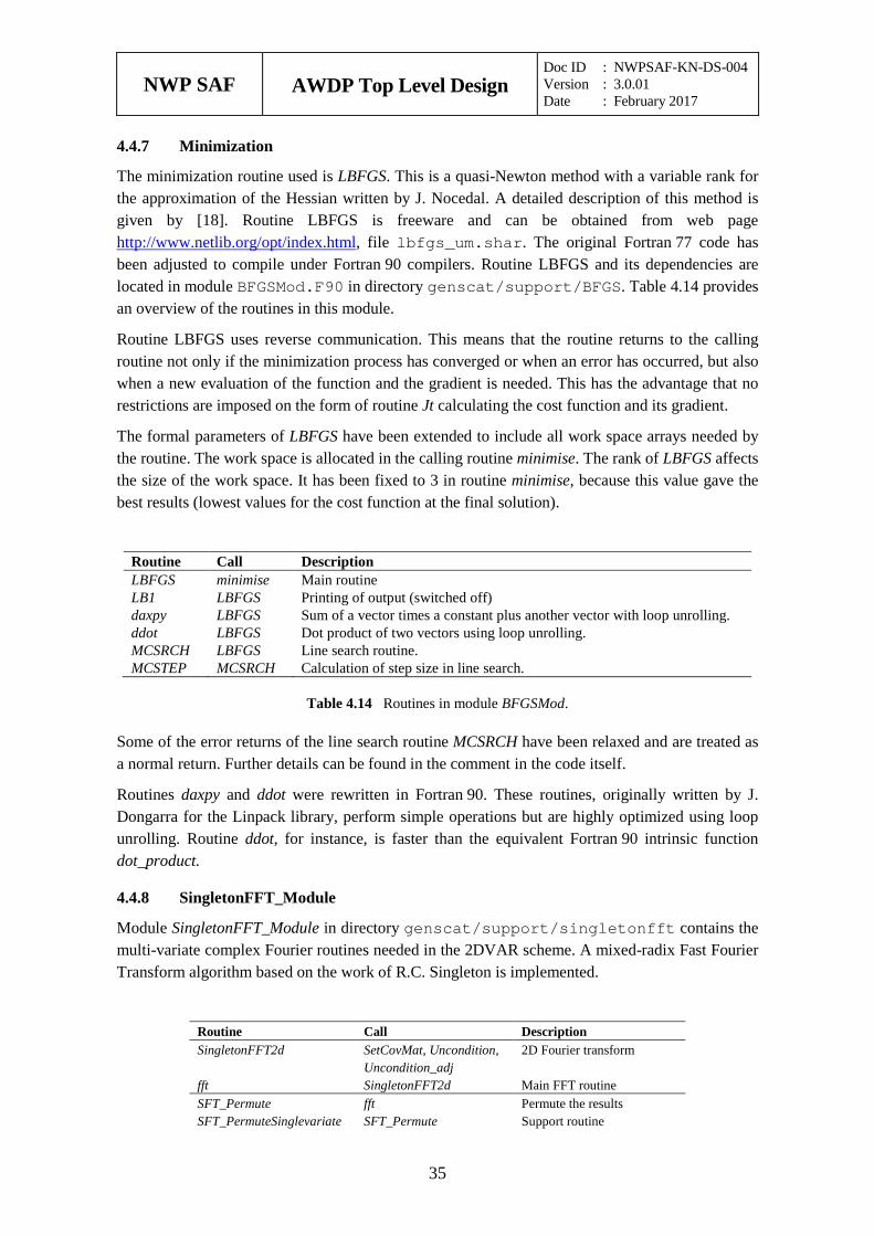
NWP SAF
AWDP Top Level Design Doc ID : NWPSAF-KN-DS-004 Version : 3.0.01 Date : February 2017
35
Minimization 4.4.7
The minimization routine used is LBFGS. This is a quasi-Newton method with a variable rank for the approximation of the Hessian written by J. Nocedal. A detailed description of this method is given by [18]. Routine LBFGS is freeware and can be obtained from web page http://www.netlib.org/opt/index.html, file lbfgs_um.shar. The original Fortran 77 code has been adjusted to compile under Fortran 90 compilers. Routine LBFGS and its dependencies are located in module BFGSMod.F90 in directory genscat/support/BFGS. Table 4.14 provides an overview of the routines in this module.
Routine LBFGS uses reverse communication. This means that the routine returns to the calling routine not only if the minimization process has converged or when an error has occurred, but also when a new evaluation of the function and the gradient is needed. This has the advantage that no restrictions are imposed on the form of routine Jt calculating the cost function and its gradient.
The formal parameters of LBFGS have been extended to include all work space arrays needed by the routine. The work space is allocated in the calling routine minimise. The rank of LBFGS affects the size of the work space. It has been fixed to 3 in routine minimise, because this value gave the best results (lowest values for the cost function at the final solution).
Routine Call Description LBFGS minimise Main routine LB1 LBFGS Printing of output (switched off) daxpy LBFGS Sum of a vector times a constant plus another vector with loop unrolling. ddot LBFGS Dot product of two vectors using loop unrolling. MCSRCH LBFGS Line search routine. MCSTEP MCSRCH Calculation of step size in line search.
Table 4.14 Routines in module BFGSMod.
Some of the error returns of the line search routine MCSRCH have been relaxed and are treated as a normal return. Further details can be found in the comment in the code itself.
Routines daxpy and ddot were rewritten in Fortran 90. These routines, originally written by J. Dongarra for the Linpack library, perform simple operations but are highly optimized using loop unrolling. Routine ddot, for instance, is faster than the equivalent Fortran 90 intrinsic function dot_product.
SingletonFFT_Module 4.4.8
Module SingletonFFT_Module in directory genscat/support/singletonfft contains the multi-variate complex Fourier routines needed in the 2DVAR scheme. A mixed-radix Fast Fourier Transform algorithm based on the work of R.C. Singleton is implemented.
Routine Call Description SingletonFFT2d SetCovMat, Uncondition,
Uncondition_adj 2D Fourier transform
fft SingletonFFT2d Main FFT routine SFT_Permute fft Permute the results SFT_PermuteSinglevariate SFT_Permute Support routine
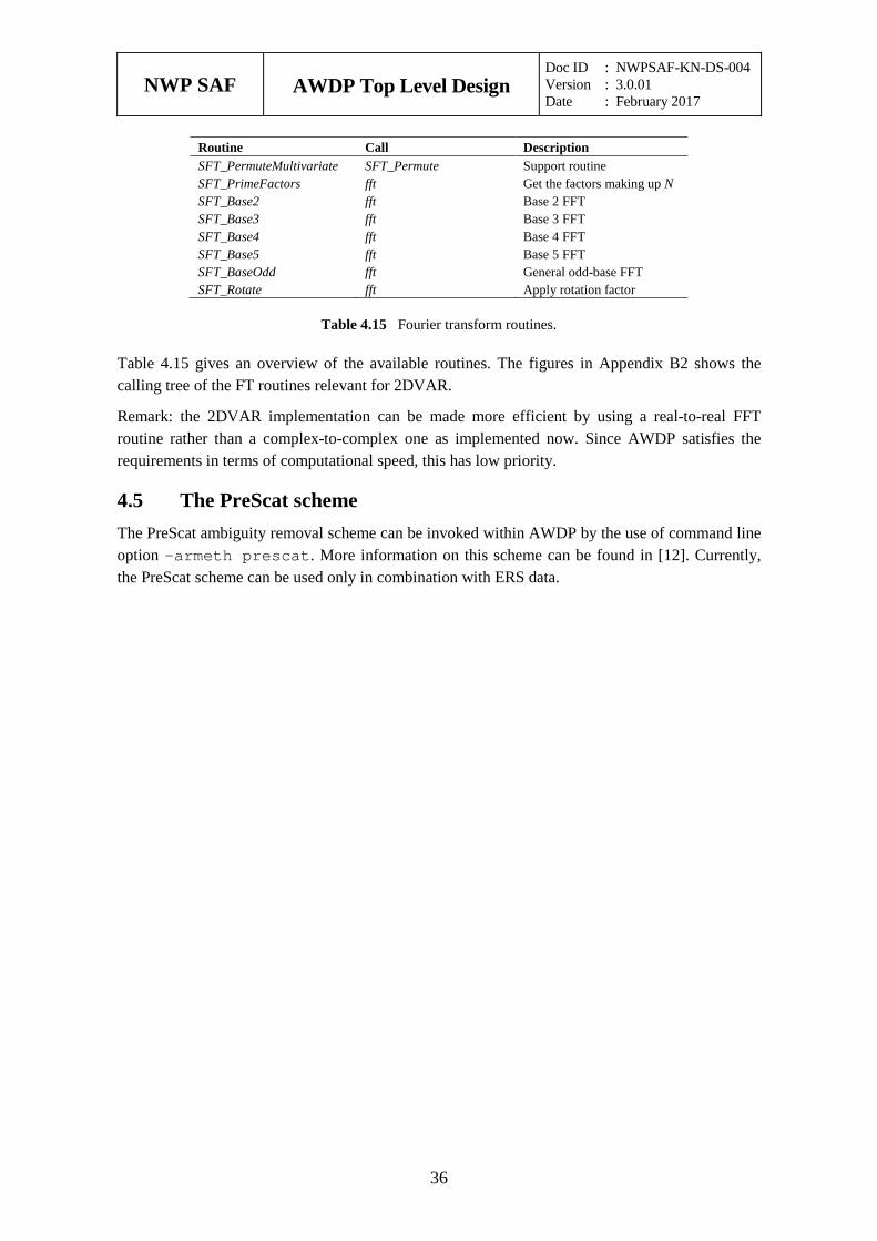
NWP SAF
AWDP Top Level Design Doc ID : NWPSAF-KN-DS-004 Version : 3.0.01 Date : February 2017
36
Routine Call Description SFT_PermuteMultivariate SFT_Permute Support routine SFT_PrimeFactors fft Get the factors making up N SFT_Base2 fft Base 2 FFT SFT_Base3 fft Base 3 FFT SFT_Base4 fft Base 4 FFT SFT_Base5 fft Base 5 FFT SFT_BaseOdd fft General odd-base FFT SFT_Rotate fft Apply rotation factor
Table 4.15 Fourier transform routines.
Table 4.15 gives an overview of the available routines. The figures in Appendix B2 shows the calling tree of the FT routines relevant for 2DVAR.
Remark: the 2DVAR implementation can be made more efficient by using a real-to-real FFT routine rather than a complex-to-complex one as implemented now. Since AWDP satisfies the requirements in terms of computational speed, this has low priority.
4.5 The PreScat scheme The PreScat ambiguity removal scheme can be invoked within AWDP by the use of command line option –armeth prescat. More information on this scheme can be found in [12]. Currently, the PreScat scheme can be used only in combination with ERS data.
NWP SAF
AWDP Top Level Design Doc ID : NWPSAF-KN-DS-004 Version : 3.0.01 Date : February 2017
37
Module iceModelMod 5
Module iceModelMod is part of the genscat support modules. It contains all the routines for initialising, reading, writing and printing of the SSM/I grids for the North Pole and South Pole region.
5.1 Background The -icemodel option in AWDP basically fills the fields Ice Probability (BUFR item 87) and Ice Age (BUFR item 88). Also it can output graphical maps of ice model related parameters on an SSM/I grid for the North Pole and for the South Pole region.
Each time the Metop satellite passes over the pole region the corresponding ice map is updated with the new ASCAT data. A spatial and temporal averaging is performed in order to digest the new information. After the overpass, at the end of processing an entire BUFR file, the updated information on the ice map is put back into the BUFR structure. Optionally graphical maps are plotted, which can be controlled by optional input parameters for routine printIceMap. The graphical filenames have encoded the North Pole/South Pole, the date/time as well as the parameter name. The most important ones are:
print_a: file [N|S][yyyymmddhhmmss].ppm contains the ice subclass and the a-ice parameter on a grey-scale for points classified as ice.
print_t: file [N|S][yyyymmddhhmmss]t.ppm contains the ice class.
print_sst: file [N|S][yyyymmddhhmmss]sst.ppm contains the sea surface temparature
print_postprob: file [N|S][yyyymmddhhmmss]postprob.ppm contains the a-posteriori ice probability.
Typically at least two days of ASCAT data are needed to entirely fill the ice map with data and give meaningful ice model output. Because AWDP handles only one BUFR file at a time, a script is needed that calls AWDP several times. After each AWDP-run a binary restart file is written to disk containing the information of an icemap (latestIceMapN.rst for the North Pole and latestIceMapS.rst for the South Pole). With the next call of awdp, these restart files are read in again. Environment variable $RESTARTDIR contains the directory for the ice model restart files.
Optionally sea surface temperature (SST) data from GRIB files can be used to further improve the quality of the ice algorithm (the use_sst logical must be turned on).
Processing l1b input with the use of NWP data and SST data can be done with the following command line options:
awdp –f <bufr file> -nwpfl <gribfilelist> -icemodel 2 –mon -handleall
NWP SAF
AWDP Top Level Design Doc ID : NWPSAF-KN-DS-004 Version : 3.0.01 Date : February 2017
38
Reprocessing of level 2 input with only running the ice model on top of it can be done with the following command line options:
awdp –f <bufr file> -icemodel 2 –noinv –noamb –mon -handleall
The SSM/I grids are widely used for representation of ice related parameters. A good description as well as some software routines can be found on the website of the National Snow and Ice Data Centre (NSIDC): http://www.nsidc.org/data/docs/daac/ae_si25_25km_tb_and_sea_ice.gd.html.
A more detailed description of the Bayesian statistics method and ice model is given in [6].
5.2 Routines Table 5.1 provides an overview of the routines in module iceModelMod.
Routine Call Description calcPoly3 AWDP Calculate a 3rd order polynomial ExpandDateTime AWDP Converts a date/time to a real ij2latlon not used Calculate lat lon values from SSM/I grid coordinates initIceMap AWDP Initialise ice map inv_logit not used Calculate the inverse of the logit of p: 1/(1+exp(-p)) latlon2ij AWDP Calculate SSM/I grid coordinates from lat lon values logit not used Calculate the logit of p: ln(p/(1-p)) MAPLL latlon2ij Convert from lat/lon to polar stereographic coordinates MAPXY ij2latlon (not used) Convert from polar stereographic to lat/lon coordinates printClass not used Print the ice class (sea or ice) print_ice_age_ascat not used Print ice age map to graphical .ppm file printIceAscat printIceMap Print ASCAT ice map to graphical .ppm file printIceMap bayesianIcemodel Print one or more ice map variables to graphical .ppm files printIcePixel AWDP Print contents of an ice pixel printIceQscat printIceMap Print QuikSCAT ice map to graphical .ppm file printppm_qc not used Print WVC quality flag contents to graphical .ppm file printppmvar printIceMap Print variable to .ppm file, mapped on gray scale printppmvars not used Print three variables to .ppm file, mapped to an RGB scale printSubclass printIceMap Print the ice subclass to a .ppm file RW_IceMap AWDP Read or write an ice map from/to a binary restart file wT AWDP Calculate the moving time average function
Table 5.1 Routines of module iceModelMod.
5.3 Data structures There are two important data structures defined in this module. The first contains all relevant data of one pixel on the ice map (IcePixel). The second one contains basically a two-dimensional array of ice pixels and represents an entire ice map (IceMapType). This could be either an ice map of the North Pole region or the South Pole region.
Attribute Type Description aIce real A ice parameter aIceAves real Average of the A ice parameter aSd real A ice parameter standard deviation class integer Ice class
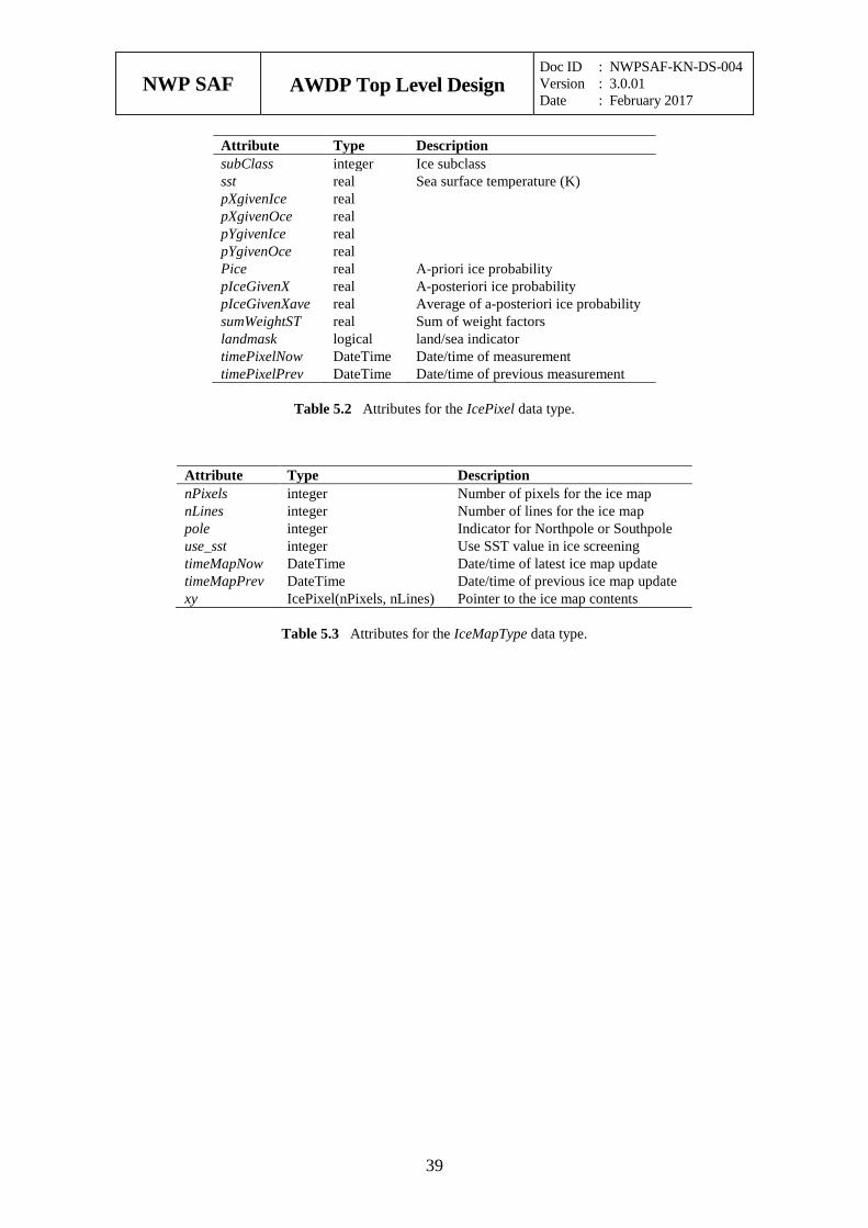
NWP SAF
AWDP Top Level Design Doc ID : NWPSAF-KN-DS-004 Version : 3.0.01 Date : February 2017
39
Attribute Type Description subClass integer Ice subclass sst real Sea surface temperature (K) pXgivenIce real pXgivenOce real pYgivenIce real pYgivenOce real Pice real A-priori ice probability pIceGivenX real A-posteriori ice probability pIceGivenXave real Average of a-posteriori ice probability sumWeightST real Sum of weight factors landmask logical land/sea indicator timePixelNow DateTime Date/time of measurement timePixelPrev DateTime Date/time of previous measurement
Table 5.2 Attributes for the IcePixel data type.
Attribute Type Description nPixels integer Number of pixels for the ice map nLines integer Number of lines for the ice map pole integer Indicator for Northpole or Southpole use_sst integer Use SST value in ice screening timeMapNow DateTime Date/time of latest ice map update timeMapPrev DateTime Date/time of previous ice map update xy IcePixel(nPixels, nLines) Pointer to the ice map contents
Table 5.3 Attributes for the IceMapType data type.
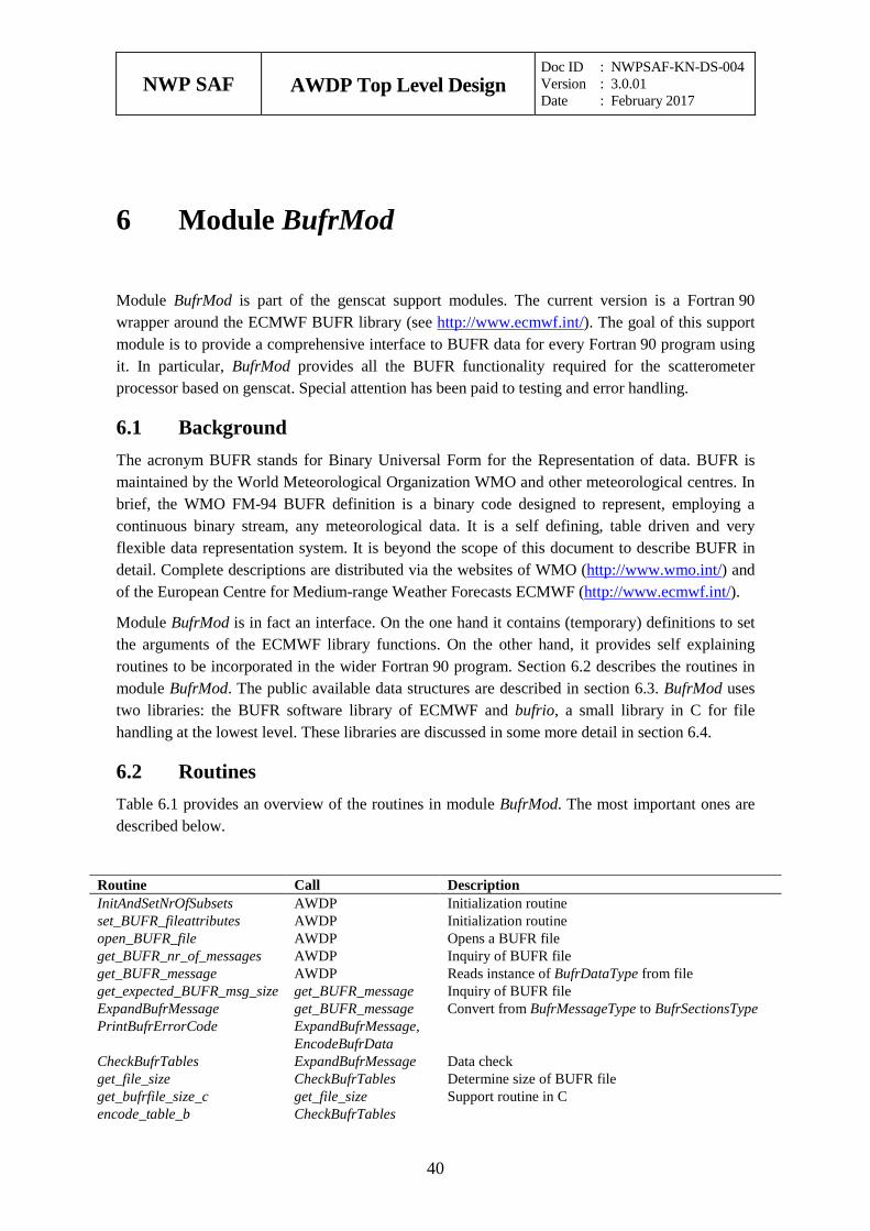
NWP SAF
AWDP Top Level Design Doc ID : NWPSAF-KN-DS-004 Version : 3.0.01 Date : February 2017
40
Module BufrMod 6
Module BufrMod is part of the genscat support modules. The current version is a Fortran 90 wrapper around the ECMWF BUFR library (see http://www.ecmwf.int/). The goal of this support module is to provide a comprehensive interface to BUFR data for every Fortran 90 program using it. In particular, BufrMod provides all the BUFR functionality required for the scatterometer processor based on genscat. Special attention has been paid to testing and error handling.
6.1 Background The acronym BUFR stands for Binary Universal Form for the Representation of data. BUFR is maintained by the World Meteorological Organization WMO and other meteorological centres. In brief, the WMO FM-94 BUFR definition is a binary code designed to represent, employing a continuous binary stream, any meteorological data. It is a self defining, table driven and very flexible data representation system. It is beyond the scope of this document to describe BUFR in detail. Complete descriptions are distributed via the websites of WMO (http://www.wmo.int/) and of the European Centre for Medium-range Weather Forecasts ECMWF (http://www.ecmwf.int/).
Module BufrMod is in fact an interface. On the one hand it contains (temporary) definitions to set the arguments of the ECMWF library functions. On the other hand, it provides self explaining routines to be incorporated in the wider Fortran 90 program. Section 6.2 describes the routines in module BufrMod. The public available data structures are described in section 6.3. BufrMod uses two libraries: the BUFR software library of ECMWF and bufrio, a small library in C for file handling at the lowest level. These libraries are discussed in some more detail in section 6.4.
6.2 Routines Table 6.1 provides an overview of the routines in module BufrMod. The most important ones are described below.
Routine Call Description InitAndSetNrOfSubsets AWDP Initialization routine set_BUFR_fileattributes AWDP Initialization routine open_BUFR_file AWDP Opens a BUFR file get_BUFR_nr_of_messages AWDP Inquiry of BUFR file get_BUFR_message AWDP Reads instance of BufrDataType from file get_expected_BUFR_msg_size get_BUFR_message Inquiry of BUFR file ExpandBufrMessage get_BUFR_message Convert from BufrMessageType to BufrSectionsType PrintBufrErrorCode ExpandBufrMessage,
EncodeBufrData
CheckBufrTables ExpandBufrMessage Data check get_file_size CheckBufrTables Determine size of BUFR file get_bufrfile_size_c get_file_size Support routine in C encode_table_b CheckBufrTables
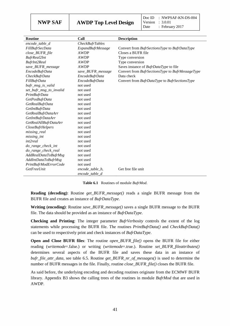
NWP SAF
AWDP Top Level Design Doc ID : NWPSAF-KN-DS-004 Version : 3.0.01 Date : February 2017
41
Routine Call Description encode_table_d CheckBufrTables FillBufrSecData ExpandBufrMessage Convert from BufrSectionsType to BufrDataType close_BUFR_file AWDP Closes a BUFR file BufrReal2Int AWDP Type conversion BufrInt2Real AWDP Type conversion save_BUFR_message AWDP Saves instance of BufrDataType to file EncodeBufrData save_BUFR_message Convert from BufrSectionsType to BufrMessageType CheckBufrData EncodeBufrData Data check FillBufrData EncodeBufrData Convert from BufrDataType to BufrSectionsType bufr_msg_is_valid not used set_bufr_msg_to_invalid not used PrintBufrData not used GetPosBufrData not used GetRealBufrData not used GetIntBufrData not used GetRealBufrDataArr not used GetIntBufrDataArr not used GetRealAllBufrDataArr not used CloseBufrHelpers not used missing_real not used missing_int not used int2real not used do_range_check_int not used do_range_check_real not used AddRealDataToBufrMsg not used AddIntDataToBufrMsg not used PrintBufrModErrorCode not used GetFreeUnit encode_table_b,
encode_table_d Get free file unit
Table 6.1 Routines of module BufrMod.
Reading (decoding): Routine get_BUFR_message() reads a single BUFR message from the BUFR file and creates an instance of BufrDataType.
Writing (encoding): Routine save_BUFR_message() saves a single BUFR message to the BUFR file. The data should be provided as an instance of BufrDataType.
Checking and Printing: The integer parameter BufrVerbosity controls the extent of the log statements while processing the BUFR file. The routines PrintBufrData() and CheckBufrData() can be used to respectively print and check instances of BufrDataType.
Open and Close BUFR files: The routine open_BUFR_file() opens the BUFR file for either reading (writemode=.false.) or writing (writemode=.true.). Routine set_BUFR_fileattributes() determines several aspects of the BUFR file and saves these data in an instance of bufr_file_attr_data, see table 6.5. Routine get_BUFR_nr_of_messages() is used to determine the number of BUFR messages in the file. Finally, routine close_BUFR_file() closes the BUFR file.
As said before, the underlying encoding and decoding routines originate from the ECMWF BUFR library. Appendix B3 shows the calling trees of the routines in module BufrMod that are used in AWDP.
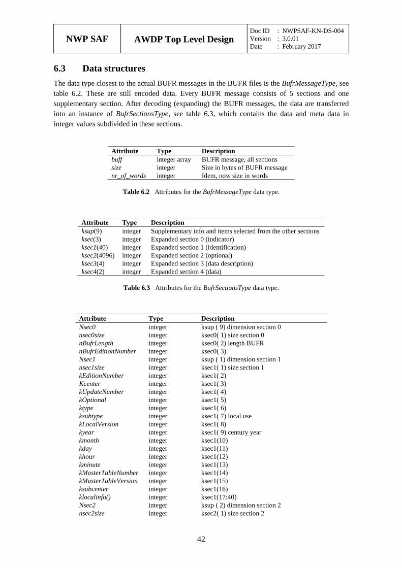
NWP SAF
AWDP Top Level Design Doc ID : NWPSAF-KN-DS-004 Version : 3.0.01 Date : February 2017
42
6.3 Data structures The data type closest to the actual BUFR messages in the BUFR files is the BufrMessageType, see table 6.2. These are still encoded data. Every BUFR message consists of 5 sections and one supplementary section. After decoding (expanding) the BUFR messages, the data are transferred into an instance of BufrSectionsType, see table 6.3, which contains the data and meta data in integer values subdivided in these sections.
Attribute Type Description buff integer array BUFR message, all sections size integer Size in bytes of BUFR message nr_of_words integer Idem, now size in words
Table 6.2 Attributes for the BufrMessageType data type.
Attribute Type Description ksup(9) integer Supplementary info and items selected from the other sections ksec(3) integer Expanded section 0 (indicator) ksec1(40) integer Expanded section 1 (identification) ksec2(4096) integer Expanded section 2 (optional) ksec3(4) integer Expanded section 3 (data description) ksec4(2) integer Expanded section 4 (data)
Table 6.3 Attributes for the BufrSectionsType data type.
Attribute Type Description Nsec0 integer ksup ( 9) dimension section 0 nsec0size integer ksec0( 1) size section 0 nBufrLength integer ksec0( 2) length BUFR nBufrEditionNumber integer ksec0( 3) Nsec1 integer ksup ( 1) dimension section 1 nsec1size integer ksec1( 1) size section 1 kEditionNumber integer ksec1( 2) Kcenter integer ksec1( 3) kUpdateNumber integer ksec1( 4) kOptional integer ksec1( 5) ktype integer ksec1( 6) ksubtype integer ksec1( 7) local use kLocalVersion integer ksec1( 8) kyear integer ksec1( 9) century year kmonth integer ksec1(10) kday integer ksec1(11) khour integer ksec1(12) kminute integer ksec1(13) kMasterTableNumber integer ksec1(14) kMasterTableVersion integer ksec1(15) ksubcenter integer ksec1(16) klocalinfo() integer ksec1(17:40) Nsec2 integer ksup ( 2) dimension section 2 nsec2size integer ksec2( 1) size section 2
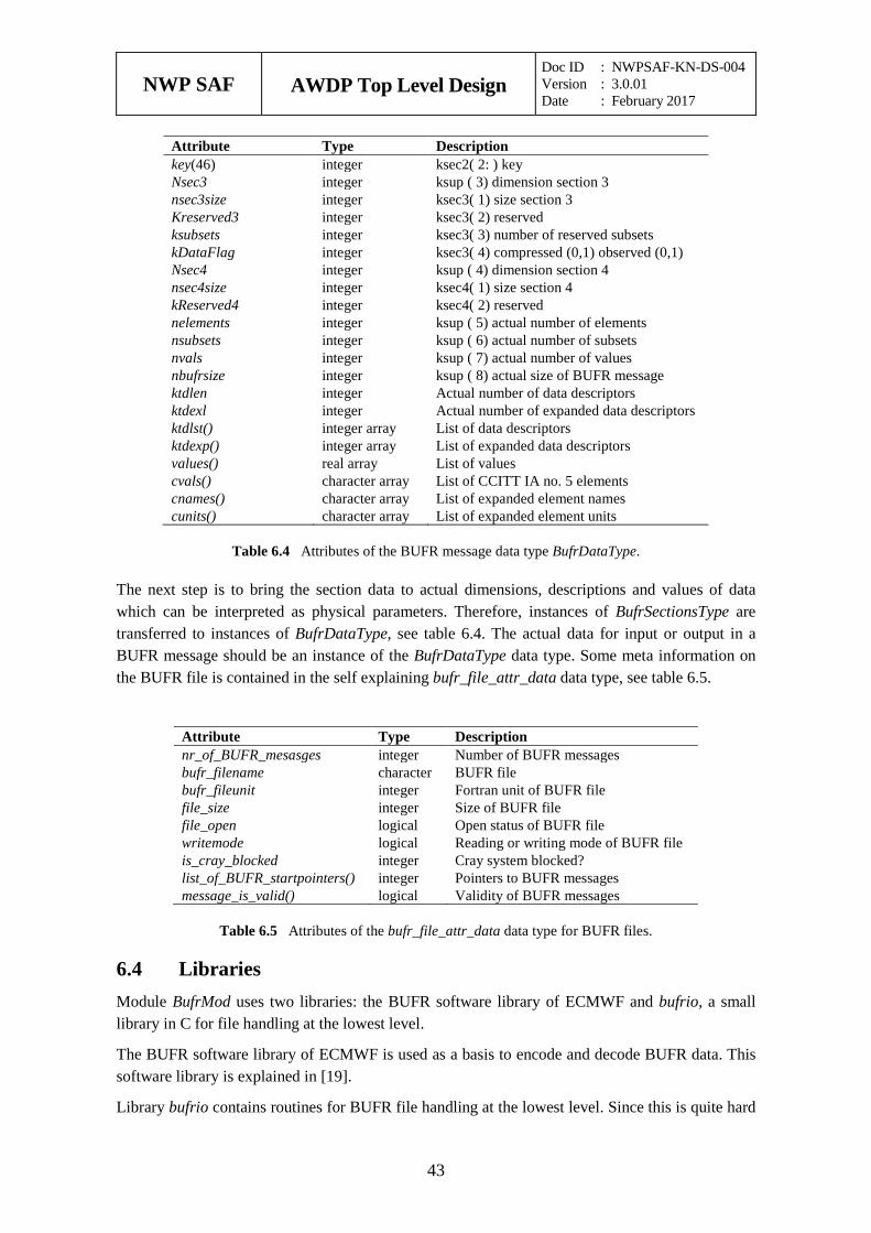
NWP SAF
AWDP Top Level Design Doc ID : NWPSAF-KN-DS-004 Version : 3.0.01 Date : February 2017
43
Attribute Type Description key(46) integer ksec2( 2: ) key Nsec3 integer ksup ( 3) dimension section 3 nsec3size integer ksec3( 1) size section 3 Kreserved3 integer ksec3( 2) reserved ksubsets integer ksec3( 3) number of reserved subsets kDataFlag integer ksec3( 4) compressed (0,1) observed (0,1) Nsec4 integer ksup ( 4) dimension section 4 nsec4size integer ksec4( 1) size section 4 kReserved4 integer ksec4( 2) reserved nelements integer ksup ( 5) actual number of elements nsubsets integer ksup ( 6) actual number of subsets nvals integer ksup ( 7) actual number of values nbufrsize integer ksup ( 8) actual size of BUFR message ktdlen integer Actual number of data descriptors ktdexl integer Actual number of expanded data descriptors ktdlst() integer array List of data descriptors ktdexp() integer array List of expanded data descriptors values() real array List of values cvals() character array List of CCITT IA no. 5 elements cnames() character array List of expanded element names cunits() character array List of expanded element units
Table 6.4 Attributes of the BUFR message data type BufrDataType.
The next step is to bring the section data to actual dimensions, descriptions and values of data which can be interpreted as physical parameters. Therefore, instances of BufrSectionsType are transferred to instances of BufrDataType, see table 6.4. The actual data for input or output in a BUFR message should be an instance of the BufrDataType data type. Some meta information on the BUFR file is contained in the self explaining bufr_file_attr_data data type, see table 6.5.
Attribute Type Description nr_of_BUFR_mesasges integer Number of BUFR messages bufr_filename character BUFR file bufr_fileunit integer Fortran unit of BUFR file file_size integer Size of BUFR file file_open logical Open status of BUFR file writemode logical Reading or writing mode of BUFR file is_cray_blocked integer Cray system blocked? list_of_BUFR_startpointers() integer Pointers to BUFR messages message_is_valid() logical Validity of BUFR messages
Table 6.5 Attributes of the bufr_file_attr_data data type for BUFR files.
6.4 Libraries Module BufrMod uses two libraries: the BUFR software library of ECMWF and bufrio, a small library in C for file handling at the lowest level.
The BUFR software library of ECMWF is used as a basis to encode and decode BUFR data. This software library is explained in [19].
Library bufrio contains routines for BUFR file handling at the lowest level. Since this is quite hard
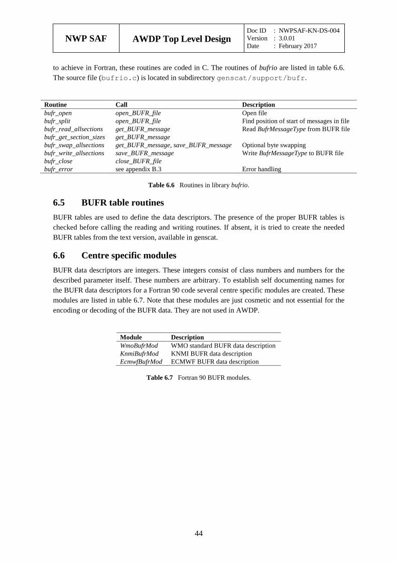
NWP SAF
AWDP Top Level Design Doc ID : NWPSAF-KN-DS-004 Version : 3.0.01 Date : February 2017
44
to achieve in Fortran, these routines are coded in C. The routines of bufrio are listed in table 6.6. The source file (bufrio.c) is located in subdirectory genscat/support/bufr.
Routine Call Description bufr_open open_BUFR_file Open file bufr_split open_BUFR_file Find position of start of messages in file bufr_read_allsections get_BUFR_message Read BufrMessageType from BUFR file bufr_get_section_sizes get_BUFR_message bufr_swap_allsections get_BUFR_message, save_BUFR_message Optional byte swapping bufr_write_allsections save_BUFR_message Write BufrMessageType to BUFR file bufr_close close_BUFR_file bufr_error see appendix B.3 Error handling
Table 6.6 Routines in library bufrio.
6.5 BUFR table routines BUFR tables are used to define the data descriptors. The presence of the proper BUFR tables is checked before calling the reading and writing routines. If absent, it is tried to create the needed BUFR tables from the text version, available in genscat.
6.6 Centre specific modules BUFR data descriptors are integers. These integers consist of class numbers and numbers for the described parameter itself. These numbers are arbitrary. To establish self documenting names for the BUFR data descriptors for a Fortran 90 code several centre specific modules are created. These modules are listed in table 6.7. Note that these modules are just cosmetic and not essential for the encoding or decoding of the BUFR data. They are not used in AWDP.
Module Description WmoBufrMod WMO standard BUFR data description KnmiBufrMod KNMI BUFR data description EcmwfBufrMod ECMWF BUFR data description
Table 6.7 Fortran 90 BUFR modules.

NWP SAF
AWDP Top Level Design Doc ID : NWPSAF-KN-DS-004 Version : 3.0.01 Date : February 2017
45
Module gribio_module 7
Module gribio_module is part of the genscat support modules. The current version is a Fortran 90 wrapper around the ECMWF GRIB API library (see http://www.ecmwf.int/). The goal of this support module is to provide a comprehensive interface to GRIB data for every Fortran 90 program using it. In particular, gribio_module provides all the GRIB functionality required for the scatterometer processor based on genscat. Special attention has been paid to testing and error handling.
7.1 Background The acronym GRIB stands for GRIdded Binary. GRIB is maintained by the World Meteorological Organization WMO and other meteorological centres. In brief, the WMO FM-92 GRIB definition is a binary format for efficiently transmitting gridded meteorological data. It is beyond the scope of this document to describe GRIB in detail. Complete descriptions are distributed via the websites of WMO (http://www.wmo.int/) and of the European Centre for Medium-range Weather Forecasts ECMWF (http://www.ecmwf.int/).
Module gribio_module is in fact an interface. On the one hand it contains (temporary) definitions to set the arguments of the ECMWF library functions. On the other hand, it provides self explaining routines to be incorporated in the wider Fortran 90 program. Section 7.2 describes the routines in module gribio_module. The available data structures are described in section 7.3. The gribio_module uses two libraries: from the GRIB software library of ECMWF. This is discussed in some more detail in section 7.4.
7.2 Routines Table 7.1 provides an overview of the routines in module gribio_module. The most important ones are described below.
Routine Call Description init_GRIB_module AWDP Initialization routine dealloc_all_GRIB_messages AWDP Clear all GRIB info from memory and
close GRIB files set_GRIB_filelist AWDP Open all necessary GRIB files get_from_GRIB_filelist AWDP,
get_colloc_from_GRIB_filelist Retrieve GRIB data for a given lat and lon
inquire_GRIB_filelist AWDP, get_analyse_dates_and_times, get_colloc_from_GRIB_filelist
Inquiry of GRIB file list
get_colloc_from_GRIB_filelist AWDP Retrieve time interpolated GRIB data for a given lat and lon
get_GRIB_msgnr get_field_from_GRIB_file, get_from_GRIB_file,
Inquiry of GRIB file list
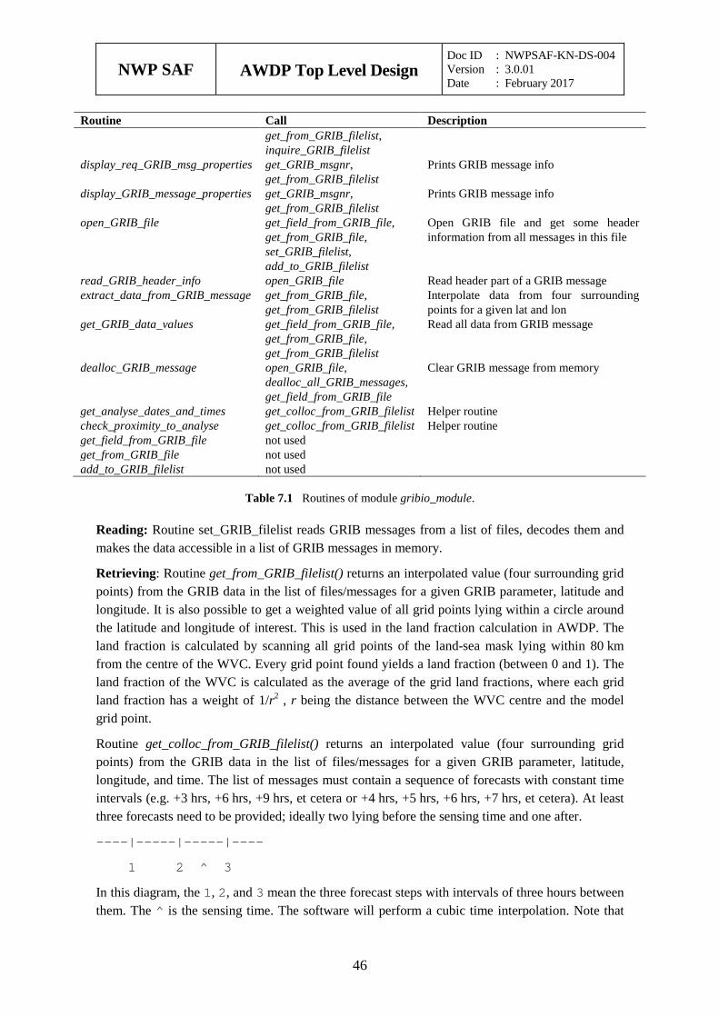
NWP SAF
AWDP Top Level Design Doc ID : NWPSAF-KN-DS-004 Version : 3.0.01 Date : February 2017
46
Routine Call Description get_from_GRIB_filelist, inquire_GRIB_filelist
display_req_GRIB_msg_properties get_GRIB_msgnr, get_from_GRIB_filelist
Prints GRIB message info
display_GRIB_message_properties get_GRIB_msgnr, get_from_GRIB_filelist
Prints GRIB message info
open_GRIB_file get_field_from_GRIB_file, get_from_GRIB_file, set_GRIB_filelist, add_to_GRIB_filelist
Open GRIB file and get some header information from all messages in this file
read_GRIB_header_info open_GRIB_file Read header part of a GRIB message extract_data_from_GRIB_message get_from_GRIB_file,
get_from_GRIB_filelist Interpolate data from four surrounding points for a given lat and lon
get_GRIB_data_values get_field_from_GRIB_file, get_from_GRIB_file, get_from_GRIB_filelist
Read all data from GRIB message
dealloc_GRIB_message open_GRIB_file, dealloc_all_GRIB_messages, get_field_from_GRIB_file
Clear GRIB message from memory
get_analyse_dates_and_times get_colloc_from_GRIB_filelist Helper routine check_proximity_to_analyse get_colloc_from_GRIB_filelist Helper routine get_field_from_GRIB_file not used get_from_GRIB_file not used add_to_GRIB_filelist not used
Table 7.1 Routines of module gribio_module.
Reading: Routine set_GRIB_filelist reads GRIB messages from a list of files, decodes them and makes the data accessible in a list of GRIB messages in memory.
Retrieving: Routine get_from_GRIB_filelist() returns an interpolated value (four surrounding grid points) from the GRIB data in the list of files/messages for a given GRIB parameter, latitude and longitude. It is also possible to get a weighted value of all grid points lying within a circle around the latitude and longitude of interest. This is used in the land fraction calculation in AWDP. The land fraction is calculated by scanning all grid points of the land-sea mask lying within 80 km from the centre of the WVC. Every grid point found yields a land fraction (between 0 and 1). The land fraction of the WVC is calculated as the average of the grid land fractions, where each grid land fraction has a weight of 1/r2 , r being the distance between the WVC centre and the model grid point.
Routine get_colloc_from_GRIB_filelist() returns an interpolated value (four surrounding grid points) from the GRIB data in the list of files/messages for a given GRIB parameter, latitude, longitude, and time. The list of messages must contain a sequence of forecasts with constant time intervals (e.g. +3 hrs, +6 hrs, +9 hrs, et cetera or +4 hrs, +5 hrs, +6 hrs, +7 hrs, et cetera). At least three forecasts need to be provided; ideally two lying before the sensing time and one after.
----|-----|-----|----
1 2 ^ 3
In this diagram, the 1, 2, and 3 mean the three forecast steps with intervals of three hours between them. The ^ is the sensing time. The software will perform a cubic time interpolation. Note that
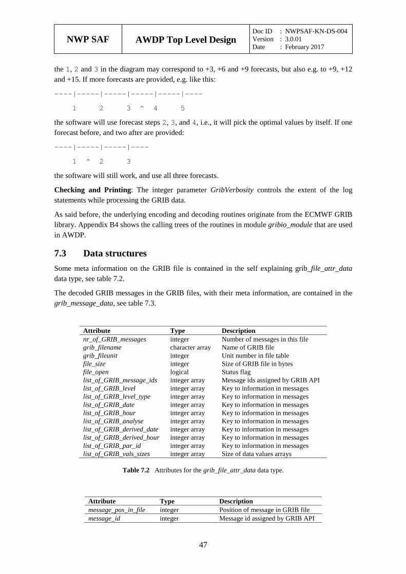
NWP SAF
AWDP Top Level Design Doc ID : NWPSAF-KN-DS-004 Version : 3.0.01 Date : February 2017
47
the 1, 2 and 3 in the diagram may correspond to +3, +6 and +9 forecasts, but also e.g. to +9, +12 and +15. If more forecasts are provided, e.g. like this:
----|-----|-----|-----|-----|----
1 2 3 ^ 4 5
the software will use forecast steps 2, 3, and 4, i.e., it will pick the optimal values by itself. If one forecast before, and two after are provided:
----|-----|-----|----
1 ^ 2 3
the software will still work, and use all three forecasts.
Checking and Printing: The integer parameter GribVerbosity controls the extent of the log statements while processing the GRIB data.
As said before, the underlying encoding and decoding routines originate from the ECMWF GRIB library. Appendix B4 shows the calling trees of the routines in module gribio_module that are used in AWDP.
7.3 Data structures Some meta information on the GRIB file is contained in the self explaining grib_file_attr_data data type, see table 7.2.
The decoded GRIB messages in the GRIB files, with their meta information, are contained in the grib_message_data, see table 7.3.
Attribute Type Description nr_of_GRIB_messages integer Number of messages in this file grib_filename character array Name of GRIB file grib_fileunit integer Unit number in file table file_size integer Size of GRIB file in bytes file_open logical Status flag list_of_GRIB_message_ids integer array Message ids assigned by GRIB API list_of_GRIB_level integer array Key to information in messages list_of_GRIB_level_type integer array Key to information in messages list_of_GRIB_date integer array Key to information in messages list_of_GRIB_hour integer array Key to information in messages list_of_GRIB_analyse integer array Key to information in messages list_of_GRIB_derived_date integer array Key to information in messages list_of_GRIB_derived_hour integer array Key to information in messages list_of_GRIB_par_id integer array Key to information in messages list_of_GRIB_vals_sizes integer array Size of data values arrays
Table 7.2 Attributes for the grib_file_attr_data data type.
Attribute Type Description message_pos_in_file integer Position of message in GRIB file message_id integer Message id assigned by GRIB API
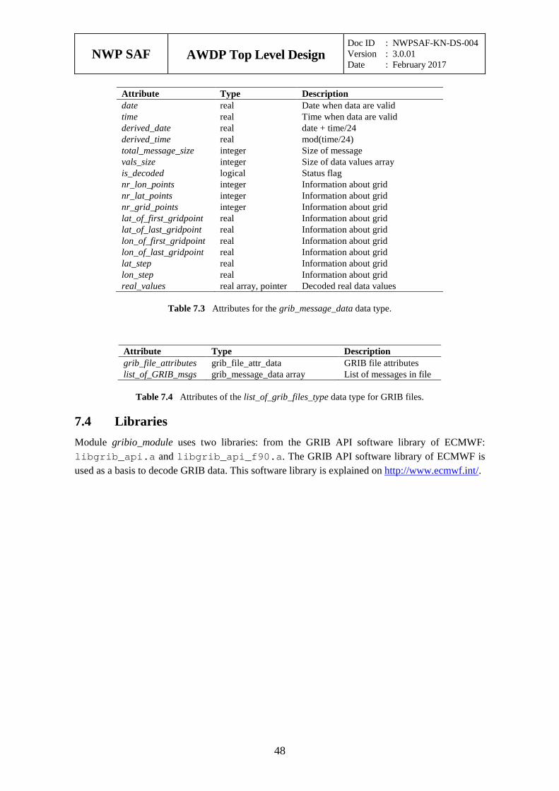
NWP SAF
AWDP Top Level Design Doc ID : NWPSAF-KN-DS-004 Version : 3.0.01 Date : February 2017
48
Attribute Type Description date real Date when data are valid time real Time when data are valid derived_date real date + time/24 derived_time real mod(time/24) total_message_size integer Size of message vals_size integer Size of data values array is_decoded logical Status flag nr_lon_points integer Information about grid nr_lat_points integer Information about grid nr_grid_points integer Information about grid lat_of_first_gridpoint real Information about grid lat_of_last_gridpoint real Information about grid lon_of_first_gridpoint real Information about grid lon_of_last_gridpoint real Information about grid lat_step real Information about grid lon_step real Information about grid real_values real array, pointer Decoded real data values
Table 7.3 Attributes for the grib_message_data data type.
Attribute Type Description grib_file_attributes grib_file_attr_data GRIB file attributes list_of_GRIB_msgs grib_message_data array List of messages in file
Table 7.4 Attributes of the list_of_grib_files_type data type for GRIB files.
7.4 Libraries Module gribio_module uses two libraries: from the GRIB API software library of ECMWF: libgrib_api.a and libgrib_api_f90.a. The GRIB API software library of ECMWF is used as a basis to decode GRIB data. This software library is explained on http://www.ecmwf.int/.
NWP SAF
AWDP Top Level Design Doc ID : NWPSAF-KN-DS-004 Version : 3.0.01 Date : February 2017
49
References
[1] Verhoef, A., Vogelzang, J., Verspeek, J. and Stoffelen, A., 2017, AWDP User Manual and Reference Guide, Report NWPSAF-KN-UD-005, EUMETSAT.
[2] Verhoef, A., Vogelzang, J., Verspeek, J. and Stoffelen, A., 2017, AWDP Product Specification, Report NWPSAF-KN-DS-003, EUMETSAT.
[3] Vogelzang, J., Verspeek, J. and Stoffelen, A., 2016, ASCAT winds on optimized grids, v1.0, Report NWPSAF-KN-TR-027 EUMETSAT. (Available on https://nwpsaf.eu/deliverables/scatterometer/index.html).
[4] Wilson, J.J.W, Figa-Saldaña, J., and O’Clerigh, E., 2004, ASCAT Product Generation Function Specification, Issue 6, Rev 5, EUMETSAT, EUM.EPS.SYS.SPE.990009 (Available on http://www.eumetsat.int/).
[5] Verspeek, J., A. Stoffelen, A. Verhoef and M. Portabella, 2012, Improved ASCAT Wind Retrieval Using NWP Ocean Calibration, IEEE Transactions on Geoscience and Remote Sensing, 2012, 50, 7, 2488-2494, doi:10.1109/TGRS.2011.2180730.
[6] Belmonte, M., J. Verspeek, A. Verhoef and A. Stoffelen, 2012, Bayesian sea ice detection with the Advanced Scatterometer, IEEE Transactions on Geoscience and Remote Sensing, 2012, 50, 7, 2649-2657, doi:10.1109/TGRS.2011.2182356.
[7] Stoffelen, A. and M. Portabella, 2006, On Bayesian Scatterometer Wind Inversion, IEEE Transactions on Geoscience and Remote Sensing, 44, 6, 1523-1533, doi:10.1109/TGRS.2005.862502.
[8] Portabella, M., 2002, Wind field retrieval from satellite radar systems, PhD thesis, University of Barcelona. (Available on http://www.knmi.nl/scatterometer/publications/).
[9] Portabella, M. and Stoffelen, A., 2001, Rain Detection and Quality Control of SeaWinds, Journal of Atm. Oceanic Technol., 18, pp. 1171-1183.
[10] Verspeek, J. and A. Stoffelen, 2015, CMOD7, OSI SAF report SAF/OSI/CDOP2/KNMI/TEC/RP/237.
[11] Vogelzang, J., 2013, Two dimensional variational ambiguity removal (2DVAR), v1.2. Report NWPSAF-KN-TR-004, UKMO, UK. (Available on http://www.knmi.nl/scatterometer/publications/ or on https://nwpsaf.eu/deliverables/scatterometer/index.html).
NWP SAF
AWDP Top Level Design Doc ID : NWPSAF-KN-DS-004 Version : 3.0.01 Date : February 2017
50
[12] Stoffelen, A., de Haan, S., Quilfen, Y., and Schyberg, H., 2000, ERS scatterometer ambiguity removal scheme comparison, OSI SAF report. (Available on http://www.knmi.nl/scatterometer/publications/).
[13] de Vries, J., Stoffelen, A., and Beysens, J., 2005, Ambiguity Removal and Product Monitoring for SeaWinds. KNMI. (Available on http://www.knmi.nl/scatterometer/publications/).
[14] de Vries, J. and Stoffelen, A., 2000, 2D Variational Ambiguity Removal. KNMI, Feb 2000. (Available on http://www.knmi.nl/scatterometer/publications/).
[15] Vogelzang, J., and Stoffelen, A., 2016, Developments in ASCAT wind ambiguity removal, v1.0. Report NWPSAF-KN-TR-026, UKMO, UK. (Available on https://nwpsaf.eu/deliverables/scatterometer/index.html).
[16] Talagrand, O., 1991, The use of adjoint equations in numerical modeling of the atmospheric circulation. In: Automatic Differentiation of Algorithms: Theory, Implementation and Application, A. Griewank and G. Corliess Eds. pp. 169-180, Philadelphia, Penn: SIAM.
[17] Giering, R., 1997, Tangent linear and Adjoint Model Compiler, Users manual. Max-Planck- Institut fuer Meteorologie.
[18] Liu, D.C., and Nocedal, J., 1989 On the limited memory BFGS method for large scale optimization methods. Mathematical Programming, 45, pp. 503-528.
[19] Dragosavac, M., 1994, BUFR User Guide and Reference Manual. ECMWF. (Available on http://www.ecmwf.int/)
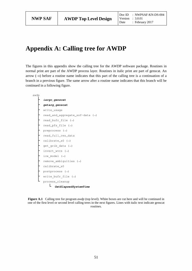
NWP SAF
AWDP Top Level Design Doc ID : NWPSAF-KN-DS-004 Version : 3.0.01 Date : February 2017
51
Appendix A: Calling tree for AWDP
The figures in this appendix show the calling tree for the AWDP software package. Routines in normal print are part of the AWDP process layer. Routines in italic print are part of genscat. An arrow (→) before a routine name indicates that this part of the calling tree is a continuation of a branch in a previous figure. The same arrow after a routine name indicates that this branch will be continued in a following figure.
awdp
├ iargc_genscat ├ getarg_genscat ├ write_usage ├ read_and_aggregate_szf-data (→) ├ read_bufr_file (→) ├ read_pfs_file (→) ├ preprocess (→) ├ read_full_res_data ├ calibrate_s0 (→) ├ get_grib_data (→) ├ invert_wvcs (→) ├ ice_model (→) ├ remove_ambiguities (→) ├ calibrate_s0 ├ postprocess (→) ├ write_bufr_file (→) └ process_cleanup └ GetElapsedSystemTime
Figure A.1 Calling tree for program awdp (top level). White boxes are cut here and will be continued in one of the first level or second level calling trees in the next figures. Lines with italic text indicate genscat
routines.
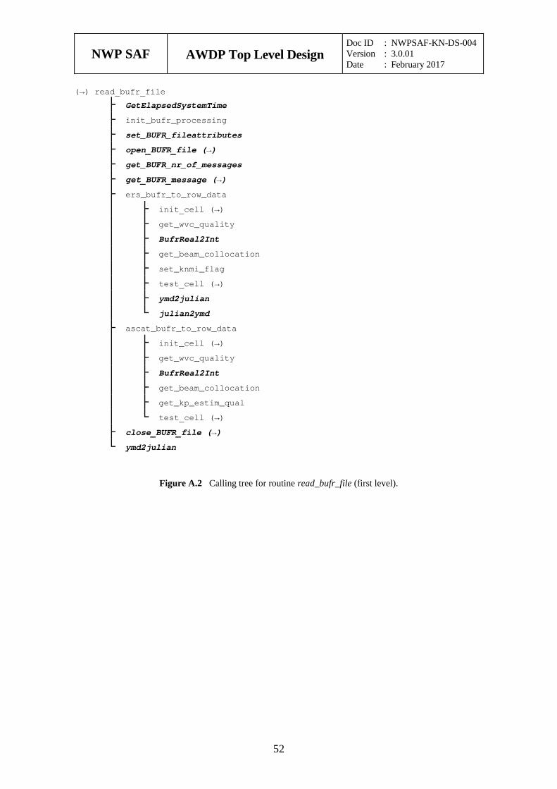
NWP SAF
AWDP Top Level Design Doc ID : NWPSAF-KN-DS-004 Version : 3.0.01 Date : February 2017
52
(→) read_bufr_file
├ GetElapsedSystemTime ├ init_bufr_processing ├ set_BUFR_fileattributes ├ open_BUFR_file (→) ├ get_BUFR_nr_of_messages ├ get_BUFR_message (→) ├ ers_bufr_to_row_data │ ├ init_cell (→) │ ├ get_wvc_quality │ ├ BufrReal2Int │ ├ get_beam_collocation │ ├ set_knmi_flag │ ├ test_cell (→) │ ├ ymd2julian │ └ julian2ymd ├ ascat_bufr_to_row_data │ ├ init_cell (→) │ ├ get_wvc_quality │ ├ BufrReal2Int │ ├ get_beam_collocation │ ├ get_kp_estim_qual │ └ test_cell (→) ├ close_BUFR_file (→) └ ymd2julian
Figure A.2 Calling tree for routine read_bufr_file (first level).
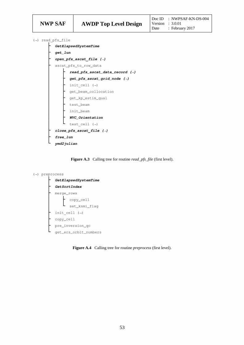
NWP SAF
AWDP Top Level Design Doc ID : NWPSAF-KN-DS-004 Version : 3.0.01 Date : February 2017
53
(→) read_pfs_file
├ GetElapsedSystemTime ├ get_lun ├ open_pfs_ascat_file (→) ├ ascat_pfs_to_row_data │ ├ read_pfs_ascat_data_record (→) │ ├ get_pfs_ascat_grid_node (→) │ ├ init_cell (→) │ ├ get_beam_collocation │ ├ get_kp_estim_qual │ ├ test_beam │ ├ init_beam │ ├ WVC_Orientation │ └ test_cell (→) ├ close_pfs_ascat_file (→) ├ free_lun └ ymd2julian
Figure A.3 Calling tree for routine read_pfs_file (first level).
(→) preprocess
├ GetElapsedSystemTime ├ GetSortIndex ├ merge_rows │ ├ copy_cell │ └ set_knmi_flag ├ init_cell (→) ├ copy_cell ├ pre_inversion_qc └ get_ers_orbit_numbers
Figure A.4 Calling tree for routine preprocess (first level).
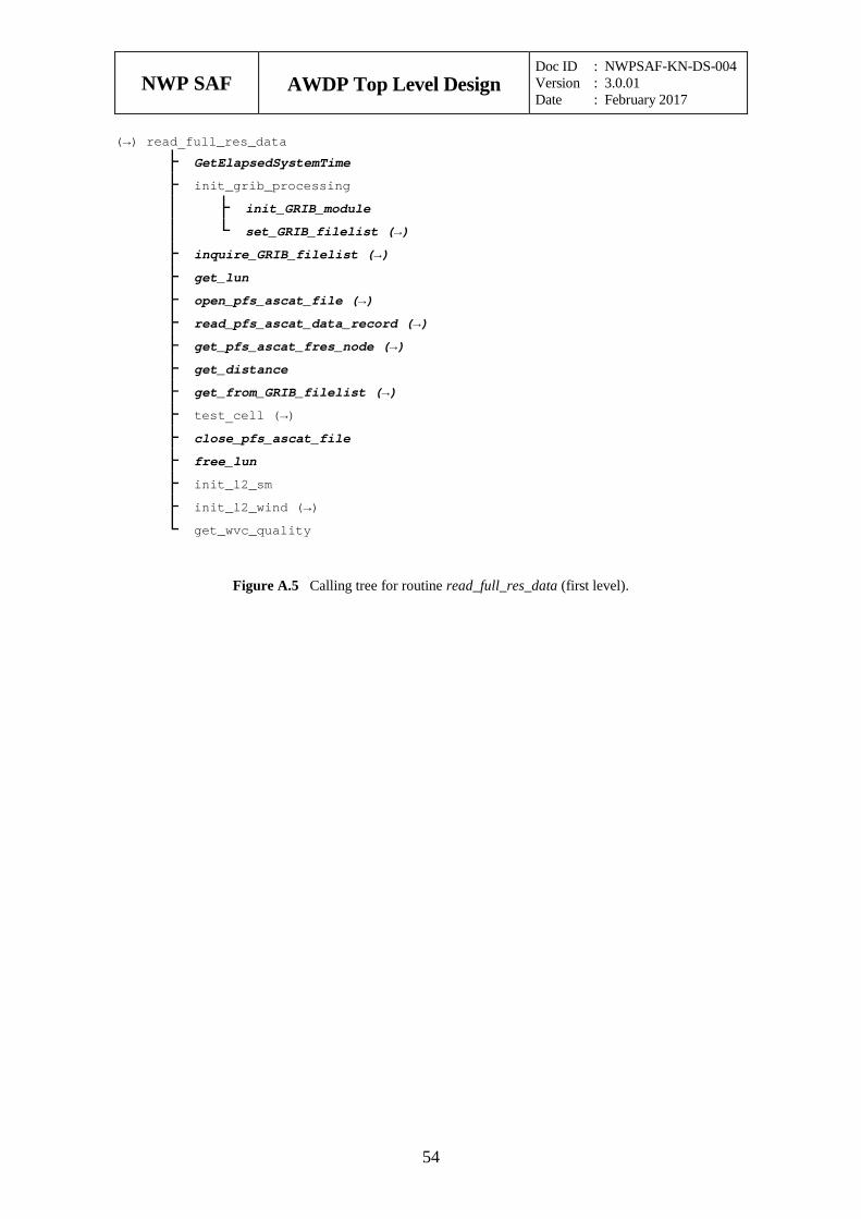
NWP SAF
AWDP Top Level Design Doc ID : NWPSAF-KN-DS-004 Version : 3.0.01 Date : February 2017
54
(→) read_full_res_data
├ GetElapsedSystemTime ├ init_grib_processing │ ├ init_GRIB_module │ └ set_GRIB_filelist (→) ├ inquire_GRIB_filelist (→) ├ get_lun ├ open_pfs_ascat_file (→) ├ read_pfs_ascat_data_record (→) ├ get_pfs_ascat_fres_node (→) ├ get_distance ├ get_from_GRIB_filelist (→) ├ test_cell (→) ├ close_pfs_ascat_file ├ free_lun ├ init_l2_sm ├ init_l2_wind (→) └ get_wvc_quality
Figure A.5 Calling tree for routine read_full_res_data (first level).
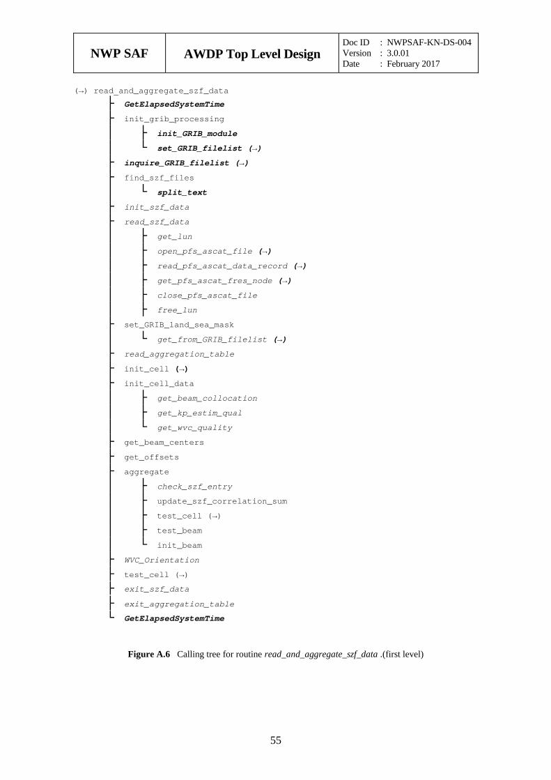
NWP SAF
AWDP Top Level Design Doc ID : NWPSAF-KN-DS-004 Version : 3.0.01 Date : February 2017
55
(→) read_and_aggregate_szf_data
├ GetElapsedSystemTime ├ init_grib_processing │ ├ init_GRIB_module │ └ set_GRIB_filelist (→) ├ inquire_GRIB_filelist (→) ├ find_szf_files │ └ split_text ├ init_szf_data ├ read_szf_data │ ├ get_lun │ ├ open_pfs_ascat_file (→) │ ├ read_pfs_ascat_data_record (→) │ ├ get_pfs_ascat_fres_node (→) │ ├ close_pfs_ascat_file │ ├ free_lun ├ set_GRIB_land_sea_mask │ └ get_from_GRIB_filelist (→) ├ read_aggregation_table ├ init_cell (→) ├ init_cell_data │ ├ get_beam_collocation │ ├ get_kp_estim_qual │ └ get_wvc_quality ├ get_beam_centers ├ get_offsets ├ aggregate │ ├ check_szf_entry │ ├ update_szf_correlation_sum │ ├ test_cell (→) │ ├ test_beam │ └ init_beam ├ WVC_Orientation ├ test_cell (→) ├ exit_szf_data ├ exit_aggregation_table └ GetElapsedSystemTime
Figure A.6 Calling tree for routine read_and_aggregate_szf_data .(first level)
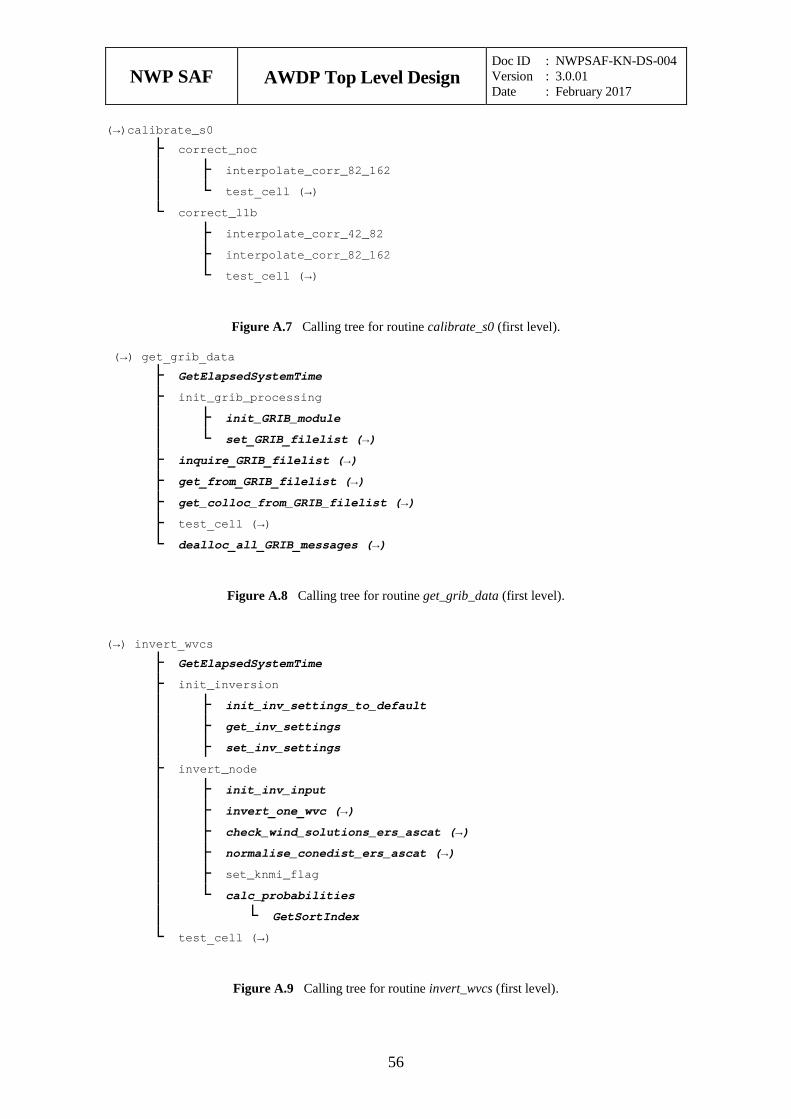
NWP SAF
AWDP Top Level Design Doc ID : NWPSAF-KN-DS-004 Version : 3.0.01 Date : February 2017
56
(→)calibrate_s0
├ correct_noc │ ├ interpolate_corr_82_162 │ └ test_cell (→) └ correct_l1b ├ interpolate_corr_42_82 ├ interpolate_corr_82_162 └ test_cell (→)
Figure A.7 Calling tree for routine calibrate_s0 (first level).
(→) get_grib_data
├ GetElapsedSystemTime ├ init_grib_processing │ ├ init_GRIB_module │ └ set_GRIB_filelist (→) ├ inquire_GRIB_filelist (→) ├ get_from_GRIB_filelist (→) ├ get_colloc_from_GRIB_filelist (→) ├ test_cell (→) └ dealloc_all_GRIB_messages (→)
Figure A.8 Calling tree for routine get_grib_data (first level).
(→) invert_wvcs
├ GetElapsedSystemTime ├ init_inversion │ ├ init_inv_settings_to_default │ ├ get_inv_settings │ ├ set_inv_settings ├ invert_node │ ├ init_inv_input │ ├ invert_one_wvc (→) │ ├ check_wind_solutions_ers_ascat (→) │ ├ normalise_conedist_ers_ascat (→) │ ├ set_knmi_flag │ └ calc_probabilities │ └ GetSortIndex └ test_cell (→)
Figure A.9 Calling tree for routine invert_wvcs (first level).
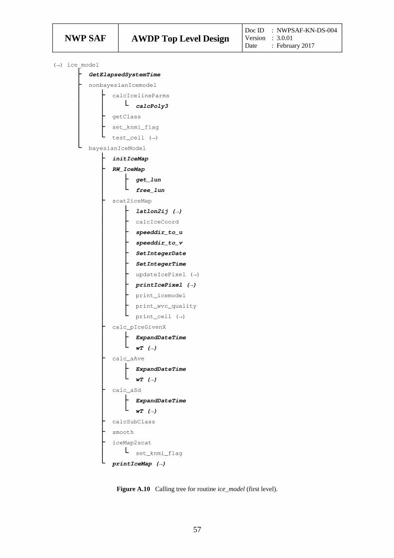
NWP SAF
AWDP Top Level Design Doc ID : NWPSAF-KN-DS-004 Version : 3.0.01 Date : February 2017
57
(→) ice_model
├ GetElapsedSystemTime ├ nonbayesianIcemodel │ ├ calcIcelineParms │ │ └ calcPoly3 │ ├ getClass │ ├ set_knmi_flag │ └ test_cell (→) └ bayesianIceModel ├ initIceMap ├ RW_IceMap │ ├ get_lun │ └ free_lun ├ scat2iceMap │ ├ latlon2ij (→) │ ├ calcIceCoord │ ├ speeddir_to_u │ ├ speeddir_to_v │ ├ SetIntegerDate │ ├ SetIntegerTime │ ├ updateIcePixel (→) │ ├ printIcePixel (→) │ ├ print_icemodel │ ├ print_wvc_quality │ └ print_cell (→) ├ calc_pIceGivenX │ ├ ExpandDateTime │ └ wT (→) ├ calc_aAve │ ├ ExpandDateTime │ └ wT (→) ├ calc_aSd │ ├ ExpandDateTime │ └ wT (→) ├ calcSubClass ├ smooth ├ iceMap2scat │ └ set_knmi_flag └ printIceMap (→)
Figure A.10 Calling tree for routine ice_model (first level).
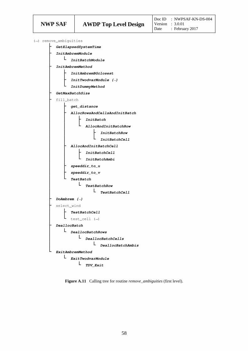
NWP SAF
AWDP Top Level Design Doc ID : NWPSAF-KN-DS-004 Version : 3.0.01 Date : February 2017
58
(→) remove_ambiguities
├ GetElapsedSystemTime ├ InitAmbremModule │ └ InitBatchModule ├ InitAmbremMethod │ ├ InitAmbremBGclosest │ ├ InitTwodvarModule (→) │ └ InitDummyMethod ├ GetMaxBatchSize ├ fill_batch │ ├ get_distance │ ├ AllocRowsAndCellsAndInitBatch │ │ ├ InitBatch │ │ └ AllocAndInitBatchRow │ │ ├ InitBatchRow │ │ └ InitBatchCell │ ├ AllocAndInitBatchCell │ │ ├ InitBatchCell │ │ └ InitBatchAmbi │ ├ speeddir_to_u │ ├ speeddir_to_v │ └ TestBatch │ └ TestBatchRow │ └ TestBatchCell ├ DoAmbrem (→) ├ select_wind │ ├ TestBatchCell │ └ test_cell (→) ├ DeallocBatch │ └ DeallocBatchRows │ └ DeallocBatchCells │ └ DeallocBatchAmbis └ ExitAmbremMethod └ ExitTwodvarModule └ TDV_Exit
Figure A.11 Calling tree for routine remove_ambiguities (first level).
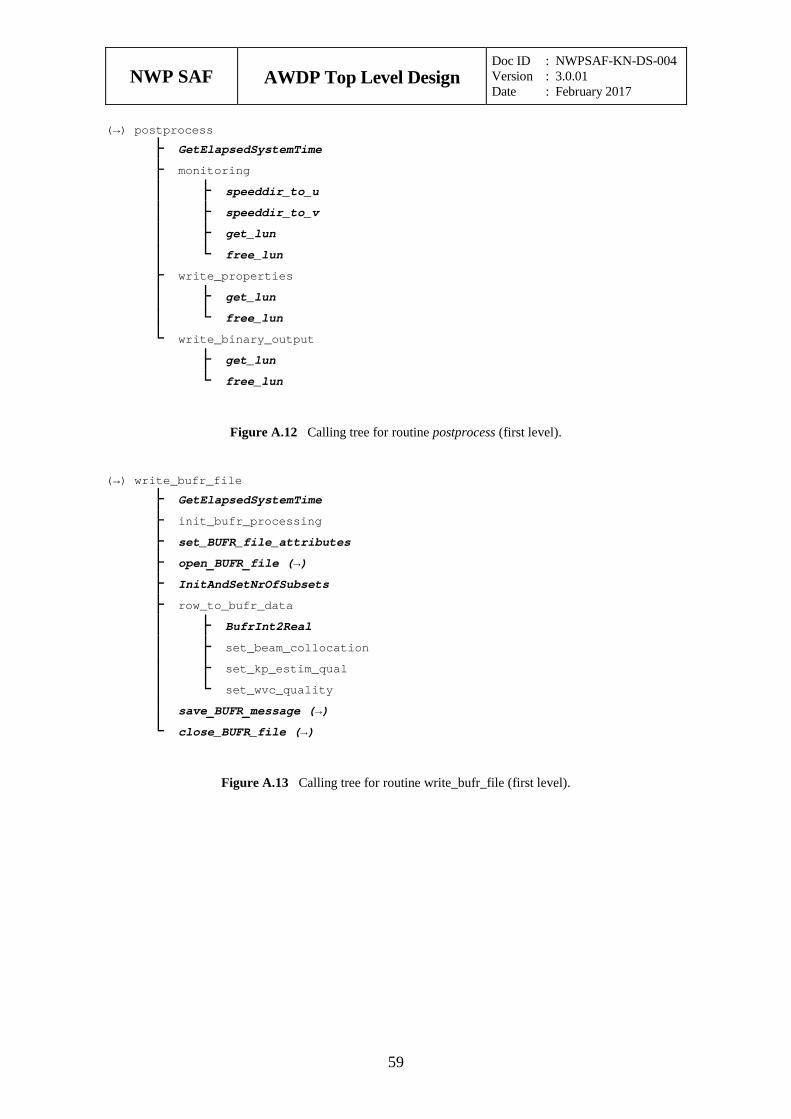
NWP SAF
AWDP Top Level Design Doc ID : NWPSAF-KN-DS-004 Version : 3.0.01 Date : February 2017
59
(→) postprocess
├ GetElapsedSystemTime ├ monitoring │ ├ speeddir_to_u │ ├ speeddir_to_v │ ├ get_lun │ └ free_lun ├ write_properties │ ├ get_lun │ └ free_lun └ write_binary_output ├ get_lun └ free_lun
Figure A.12 Calling tree for routine postprocess (first level).
(→) write_bufr_file
├ GetElapsedSystemTime ├ init_bufr_processing ├ set_BUFR_file_attributes ├ open_BUFR_file (→) ├ InitAndSetNrOfSubsets ├ row_to_bufr_data │ ├ BufrInt2Real │ ├ set_beam_collocation │ ├ set_kp_estim_qual │ └ set_wvc_quality │ save_BUFR_message (→) └ close_BUFR_file (→)
Figure A.13 Calling tree for routine write_bufr_file (first level).
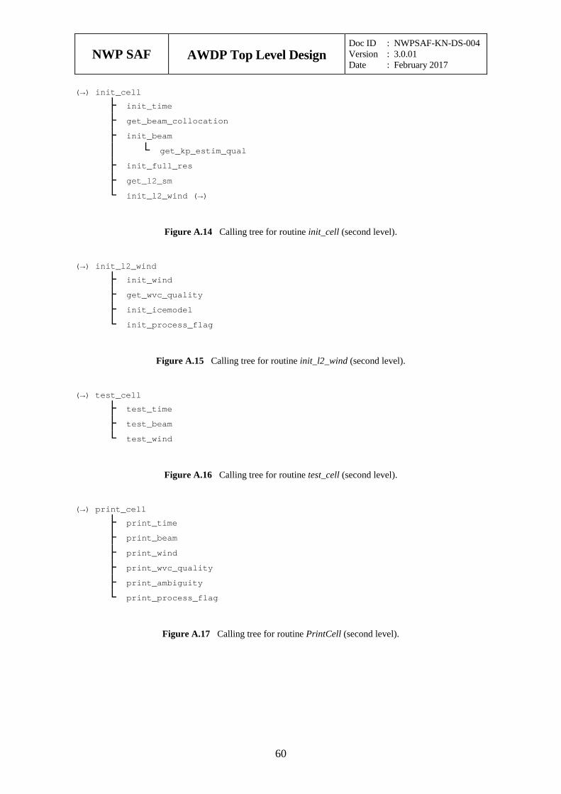
NWP SAF
AWDP Top Level Design Doc ID : NWPSAF-KN-DS-004 Version : 3.0.01 Date : February 2017
60
(→) init_cell
├ init_time ├ get_beam_collocation ├ init_beam │ └ get_kp_estim_qual ├ init_full_res ├ get_l2_sm └ init_l2_wind (→)
Figure A.14 Calling tree for routine init_cell (second level).
(→) init_l2_wind
├ init_wind ├ get_wvc_quality ├ init_icemodel └ init_process_flag
Figure A.15 Calling tree for routine init_l2_wind (second level).
(→) test_cell
├ test_time ├ test_beam └ test_wind
Figure A.16 Calling tree for routine test_cell (second level).
(→) print_cell
├ print_time ├ print_beam ├ print_wind ├ print_wvc_quality ├ print_ambiguity └ print_process_flag
Figure A.17 Calling tree for routine PrintCell (second level).

NWP SAF
AWDP Top Level Design Doc ID : NWPSAF-KN-DS-004 Version : 3.0.01 Date : February 2017
61
(→)calcIceCoord
└ calcIcelineParms └ calcPoly3
Figure A.18 Calling tree for routine calcIceCoord (second level).
(→)updateIcePixel
├ ExpandDateTime ├ getClass └ getPx
Figure A.19 Calling tree for routine updateIcePixel (second level).
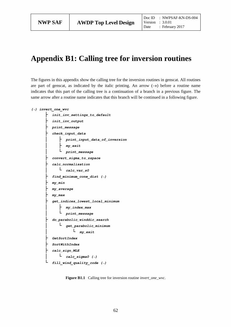
NWP SAF
AWDP Top Level Design Doc ID : NWPSAF-KN-DS-004 Version : 3.0.01 Date : February 2017
62
Appendix B1: Calling tree for inversion routines
The figures in this appendix show the calling tree for the inversion routines in genscat. All routines are part of genscat, as indicated by the italic printing. An arrow (→) before a routine name indicates that this part of the calling tree is a continuation of a branch in a previous figure. The same arrow after a routine name indicates that this branch will be continued in a following figure.
(→) invert_one_wvc
├ init_inv_settings_to_default ├ init_inv_output ├ print_message ├ check_input_data │ ├ print_input_data_of_inversion │ ├ my_exit │ └ print_message ├ convert_sigma_to_zspace ├ calc_normalisation │ └ calc_var_s0 ├ find_minimum_cone_dist (→) ├ my_min ├ my_average ├ my_max ├ get_indices_lowest_local_minimum │ ├ my_index_max │ └ print_message ├ do_parabolic_winddir_search │ └ get_parabolic_minimum │ └ my_exit ├ GetSortIndex ├ SortWithIndex ├ calc_sign_MLE │ └ calc_sigma0 (→) └ fill_wind_quality_code (→)
Figure B1.1 Calling tree for inversion routine invert_one_wvc.
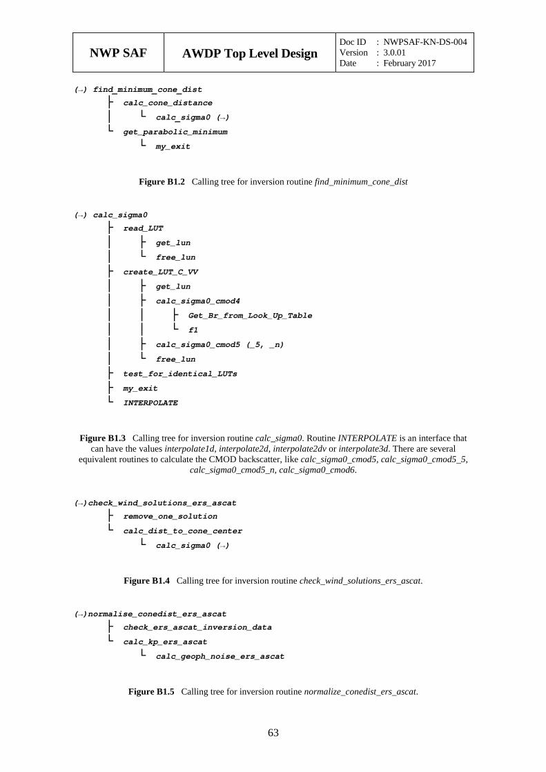
NWP SAF
AWDP Top Level Design Doc ID : NWPSAF-KN-DS-004 Version : 3.0.01 Date : February 2017
63
(→) find_minimum_cone_dist
├ calc_cone_distance │ └ calc_sigma0 (→) └ get_parabolic_minimum └ my_exit
Figure B1.2 Calling tree for inversion routine find_minimum_cone_dist
(→) calc_sigma0
├ read_LUT │ ├ get_lun │ └ free_lun ├ create_LUT_C_VV │ ├ get_lun │ ├ calc_sigma0_cmod4 │ │ ├ Get_Br_from_Look_Up_Table │ │ └ f1 │ ├ calc_sigma0_cmod5 (_5, _n) │ └ free_lun ├ test_for_identical_LUTs ├ my_exit └ INTERPOLATE
Figure B1.3 Calling tree for inversion routine calc_sigma0. Routine INTERPOLATE is an interface that can have the values interpolate1d, interpolate2d, interpolate2dv or interpolate3d. There are several
equivalent routines to calculate the CMOD backscatter, like calc_sigma0_cmod5, calc_sigma0_cmod5_5, calc_sigma0_cmod5_n, calc_sigma0_cmod6.
(→)check_wind_solutions_ers_ascat
├ remove_one_solution └ calc_dist_to_cone_center └ calc_sigma0 (→)
Figure B1.4 Calling tree for inversion routine check_wind_solutions_ers_ascat.
(→)normalise_conedist_ers_ascat
├ check_ers_ascat_inversion_data └ calc_kp_ers_ascat └ calc_geoph_noise_ers_ascat
Figure B1.5 Calling tree for inversion routine normalize_conedist_ers_ascat.
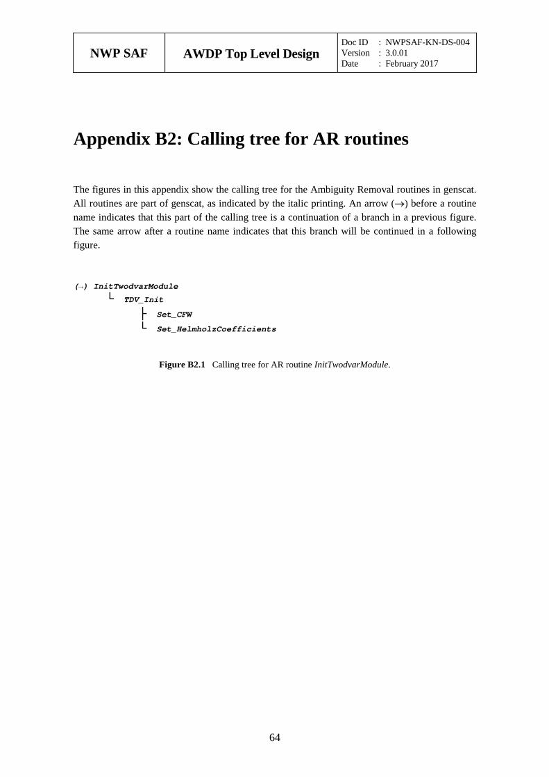
NWP SAF
AWDP Top Level Design Doc ID : NWPSAF-KN-DS-004 Version : 3.0.01 Date : February 2017
64
Appendix B2: Calling tree for AR routines
The figures in this appendix show the calling tree for the Ambiguity Removal routines in genscat. All routines are part of genscat, as indicated by the italic printing. An arrow (→) before a routine name indicates that this part of the calling tree is a continuation of a branch in a previous figure. The same arrow after a routine name indicates that this branch will be continued in a following figure.
(→) InitTwodvarModule
└ TDV_Init ├ Set_CFW └ Set_HelmholzCoefficients
Figure B2.1 Calling tree for AR routine InitTwodvarModule.
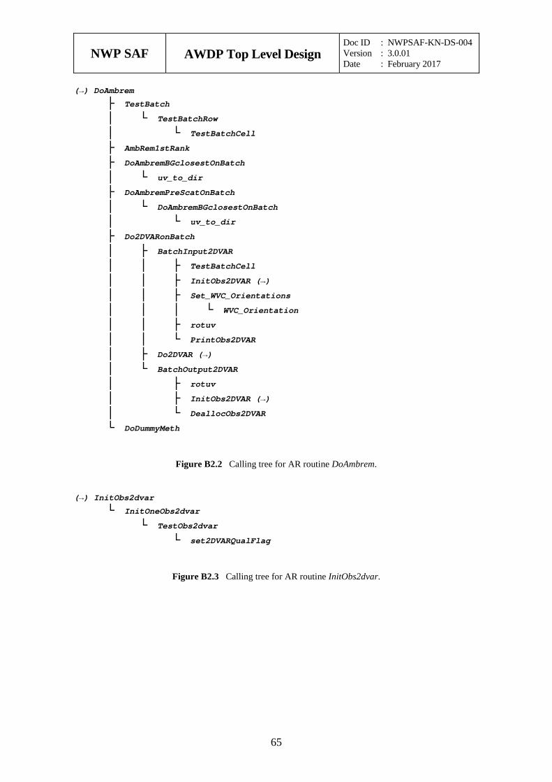
NWP SAF
AWDP Top Level Design Doc ID : NWPSAF-KN-DS-004 Version : 3.0.01 Date : February 2017
65
(→) DoAmbrem
├ TestBatch │ └ TestBatchRow │ └ TestBatchCell ├ AmbRem1stRank ├ DoAmbremBGclosestOnBatch │ └ uv_to_dir ├ DoAmbremPreScatOnBatch │ └ DoAmbremBGclosestOnBatch │ └ uv_to_dir ├ Do2DVARonBatch │ ├ BatchInput2DVAR │ │ ├ TestBatchCell │ │ ├ InitObs2DVAR (→) │ │ ├ Set_WVC_Orientations │ │ │ └ WVC_Orientation │ │ ├ rotuv │ │ └ PrintObs2DVAR │ ├ Do2DVAR (→) │ └ BatchOutput2DVAR │ ├ rotuv │ ├ InitObs2DVAR (→) │ └ DeallocObs2DVAR └ DoDummyMeth
Figure B2.2 Calling tree for AR routine DoAmbrem.
(→) InitObs2dvar
└ InitOneObs2dvar └ TestObs2dvar └ set2DVARQualFlag
Figure B2.3 Calling tree for AR routine InitObs2dvar.
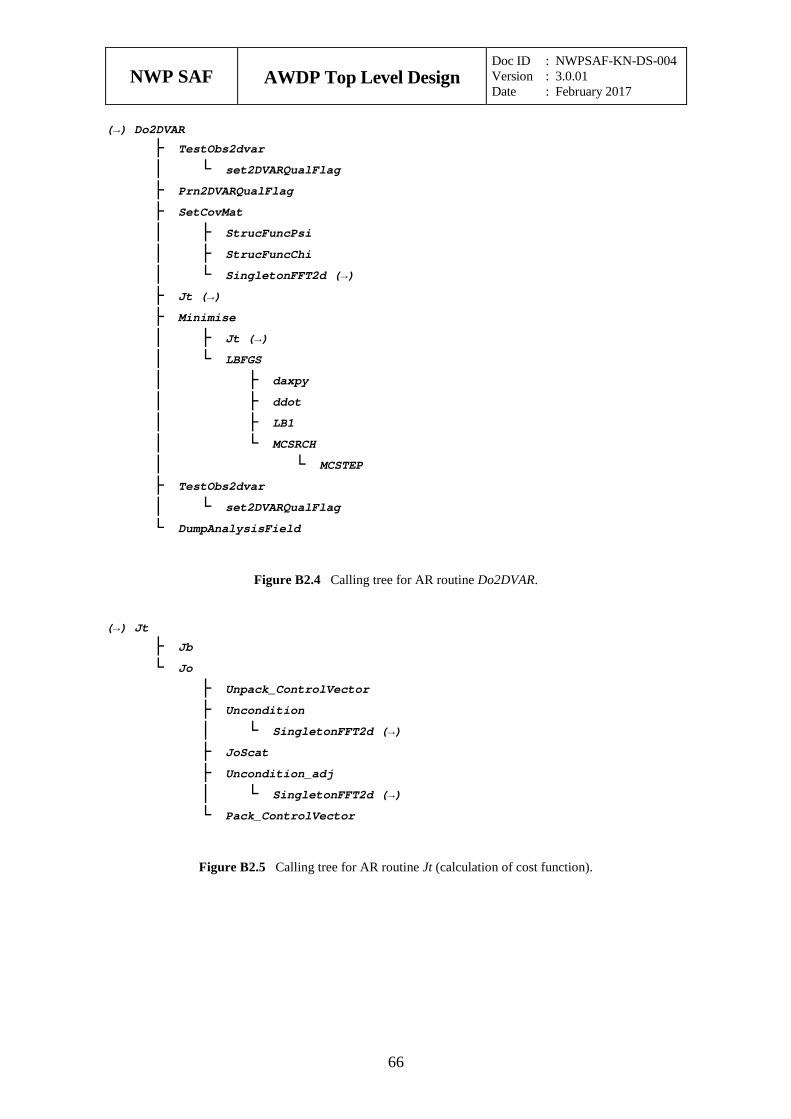
NWP SAF
AWDP Top Level Design Doc ID : NWPSAF-KN-DS-004 Version : 3.0.01 Date : February 2017
66
(→) Do2DVAR
├ TestObs2dvar │ └ set2DVARQualFlag ├ Prn2DVARQualFlag ├ SetCovMat │ ├ StrucFuncPsi │ ├ StrucFuncChi │ └ SingletonFFT2d (→) ├ Jt (→) ├ Minimise │ ├ Jt (→) │ └ LBFGS │ ├ daxpy │ ├ ddot │ ├ LB1 │ └ MCSRCH │ └ MCSTEP ├ TestObs2dvar │ └ set2DVARQualFlag └ DumpAnalysisField
Figure B2.4 Calling tree for AR routine Do2DVAR.
(→) Jt
├ Jb └ Jo ├ Unpack_ControlVector ├ Uncondition │ └ SingletonFFT2d (→) ├ JoScat ├ Uncondition_adj │ └ SingletonFFT2d (→) └ Pack_ControlVector
Figure B2.5 Calling tree for AR routine Jt (calculation of cost function).
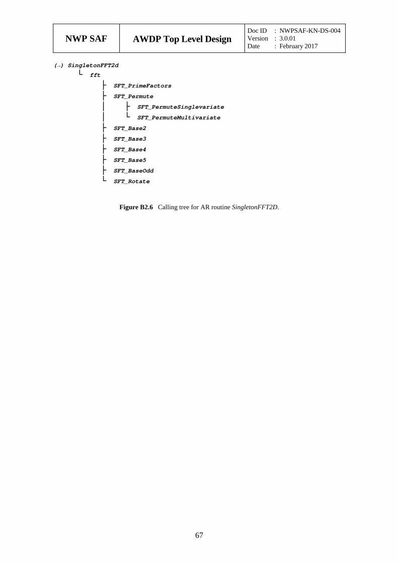
NWP SAF
AWDP Top Level Design Doc ID : NWPSAF-KN-DS-004 Version : 3.0.01 Date : February 2017
67
(→) SingletonFFT2d
└ fft ├ SFT_PrimeFactors ├ SFT_Permute │ ├ SFT_PermuteSinglevariate │ └ SFT_PermuteMultivariate ├ SFT_Base2 ├ SFT_Base3 ├ SFT_Base4 ├ SFT_Base5 ├ SFT_BaseOdd └ SFT_Rotate
Figure B2.6 Calling tree for AR routine SingletonFFT2D.
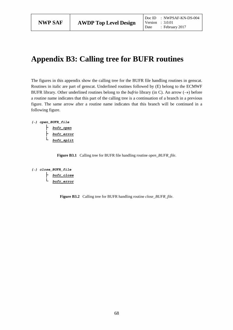
NWP SAF
AWDP Top Level Design Doc ID : NWPSAF-KN-DS-004 Version : 3.0.01 Date : February 2017
68
Appendix B3: Calling tree for BUFR routines
The figures in this appendix show the calling tree for the BUFR file handling routines in genscat. Routines in italic are part of genscat. Underlined routines followed by (E) belong to the ECMWF BUFR library. Other underlined routines belong to the bufrio library (in C). An arrow (→) before a routine name indicates that this part of the calling tree is a continuation of a branch in a previous figure. The same arrow after a routine name indicates that this branch will be continued in a following figure.
(→) open_BUFR_file
├ bufr_open ├ bufr_error └ bufr_split
Figure B3.1 Calling tree for BUFR file handling routine open_BUFR_file.
(→) close_BUFR_file
├ bufr_close └ bufr_error
Figure B3.2 Calling tree for BUFR handling routine close_BUFR_file.

NWP SAF
AWDP Top Level Design Doc ID : NWPSAF-KN-DS-004 Version : 3.0.01 Date : February 2017
69
(→) get_BUFR_message
├ get_expected_BUFR_msg_size ├ bufr_read_allsections ├ bufr_error ├ bufr_get_section_sizes ├ bufr_swap_allsections └ ExpandBufrMessage ├ BUS012 (E) ├ PrintBufrErrorCode ├ CheckBufrTables │ ├ get_file_size │ ├ encode_table_b │ └ encode_table_d ├ BUFREX (E) ├ FillBufrSecData └ BUSEL (E)
Figure B3.3 Calling tree for BUFR handling routine get_BUFR_message.
(→) save_BUFR_message
├ EncodeBufrData │ ├ CheckBufrData │ ├ FillBufrData │ ├ BUFREN (E) │ └ PrintBufrErrorCode ├ bufr_swap_allsections ├ bufr_write_allsections └ bufr_error
Figure B3.4 Calling tree for BUFR file handling routine save_BUFR_file.
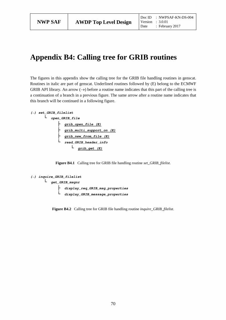
NWP SAF
AWDP Top Level Design Doc ID : NWPSAF-KN-DS-004 Version : 3.0.01 Date : February 2017
70
Appendix B4: Calling tree for GRIB routines
The figures in this appendix show the calling tree for the GRIB file handling routines in genscat. Routines in italic are part of genscat. Underlined routines followed by (E) belong to the ECMWF GRIB API library. An arrow (→) before a routine name indicates that this part of the calling tree is a continuation of a branch in a previous figure. The same arrow after a routine name indicates that this branch will be continued in a following figure.
(→) set_GRIB_filelist
└ open_GRIB_file ├ grib_open_file (E) ├ grib_multi_support_on (E) ├ grib_new_from_file (E) └ read_GRIB_header_info └ grib_get (E)
Figure B4.1 Calling tree for GRIB file handling routine set_GRIB_filelist.
(→) inquire_GRIB_filelist
└ get_GRIB_msgnr ├ display_req_GRIB_msg_properties └ display_GRIB_message_properties
Figure B4.2 Calling tree for GRIB file handling routine inquire_GRIB_filelist.

NWP SAF
AWDP Top Level Design Doc ID : NWPSAF-KN-DS-004 Version : 3.0.01 Date : February 2017
71
(→) get_from_GRIB_filelist
├ get_GRIB_msgnr │ ├ display_req_GRIB_msg_properties │ └ display_GRIB_message_properties ├ display_req_GRIB_msg_properties ├ display_GRIB_message_properties ├ get_GRIB_data_values │ ├ grib_get (E) │ ├ grib_is_missing (E) │ └ grib_set (E) ├ get_angle_distance └ extract_data_from_GRIB_message
Figure B4.3 Calling tree for GRIB file handling routine get_from_GRIB_filelist.
(→) get_colloc_from_GRIB_filelist
├ convert_to_derived_datetime │ └ conv_date_to_daycount ├ get_analyse_date_and_times │ └ inquire_GRIB_filelist (→) ├ check_proximity_to_analyse │ └ conv_date_to_daycount ├ inquire_GRIB_filelist (→) └ get_from_GRIB_filelist (→)
Figure B4.4 Calling tree for GRIB file handling routine get_colloc_from_GRIB_filelist.
(→) dealloc_all_GRIB_messages
├ dealloc_GRIB_message ├ grib_release (E) └ grib_close_file (E)
Figure B4.5 Calling tree for GRIB file handling routine dealloc_all_GRIB_messages.
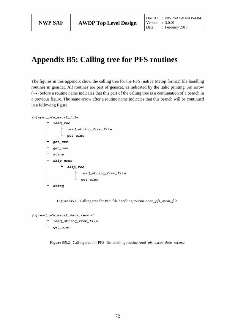
NWP SAF
AWDP Top Level Design Doc ID : NWPSAF-KN-DS-004 Version : 3.0.01 Date : February 2017
72
Appendix B5: Calling tree for PFS routines
The figures in this appendix show the calling tree for the PFS (native Metop format) file handling routines in genscat. All routines are part of genscat, as indicated by the italic printing. An arrow (→) before a routine name indicates that this part of the calling tree is a continuation of a branch in a previous figure. The same arrow after a routine name indicates that this branch will be continued in a following figure.
(→)open_pfs_ascat_file
├ read_rec │ ├ read_string_from_file │ └ get_uint ├ get_str ├ get_num ├ strne ├ skip_nrec │ └ skip_rec │ ├ read_string_from_file │ └ get_uint └ streq
Figure B5.1 Calling tree for PFS file handling routine open_pfs_ascat_file.
(→)read_pfs_ascat_data_record
├ read_string_from_file └ get_uint
Figure B5.2 Calling tree for PFS file handling routine read_pfs_ascat_data_record.
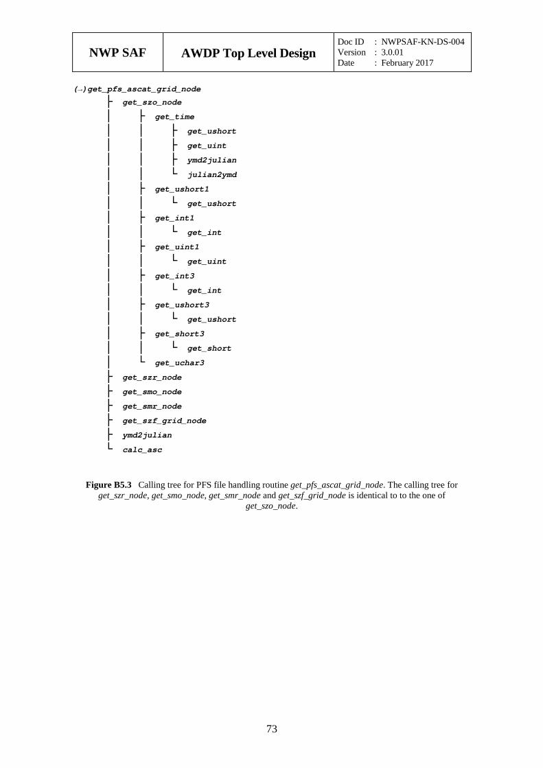
NWP SAF
AWDP Top Level Design Doc ID : NWPSAF-KN-DS-004 Version : 3.0.01 Date : February 2017
73
(→)get_pfs_ascat_grid_node
├ get_szo_node │ ├ get_time │ │ ├ get_ushort │ │ ├ get_uint │ │ ├ ymd2julian │ │ └ julian2ymd │ ├ get_ushort1 │ │ └ get_ushort │ ├ get_int1 │ │ └ get_int │ ├ get_uint1 │ │ └ get_uint │ ├ get_int3 │ │ └ get_int │ ├ get_ushort3 │ │ └ get_ushort │ ├ get_short3 │ │ └ get_short │ └ get_uchar3 ├ get_szr_node ├ get_smo_node ├ get_smr_node ├ get_szf_grid_node ├ ymd2julian └ calc_asc
Figure B5.3 Calling tree for PFS file handling routine get_pfs_ascat_grid_node. The calling tree for get_szr_node, get_smo_node, get_smr_node and get_szf_grid_node is identical to to the one of
get_szo_node.
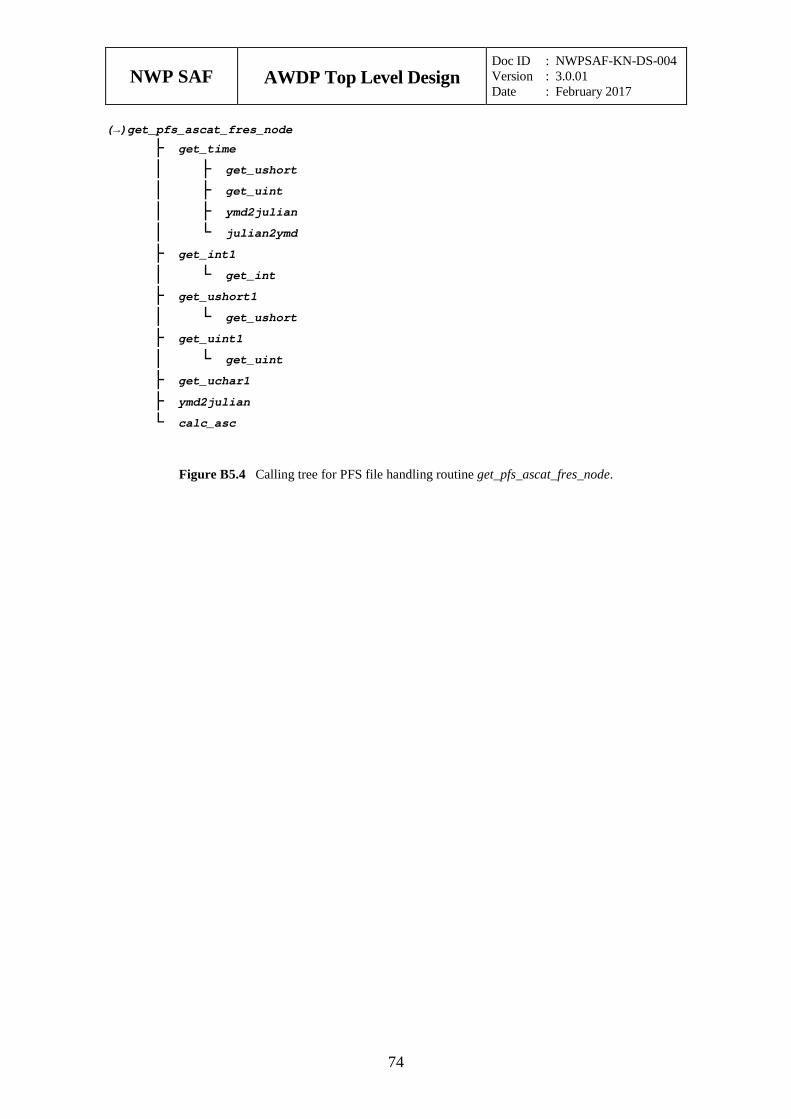
NWP SAF
AWDP Top Level Design Doc ID : NWPSAF-KN-DS-004 Version : 3.0.01 Date : February 2017
74
(→)get_pfs_ascat_fres_node
├ get_time │ ├ get_ushort │ ├ get_uint │ ├ ymd2julian │ └ julian2ymd ├ get_int1 │ └ get_int ├ get_ushort1 │ └ get_ushort ├ get_uint1 │ └ get_uint ├ get_uchar1 ├ ymd2julian └ calc_asc
Figure B5.4 Calling tree for PFS file handling routine get_pfs_ascat_fres_node.
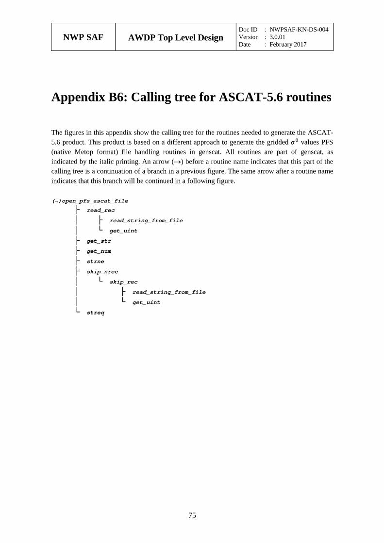
NWP SAF
AWDP Top Level Design Doc ID : NWPSAF-KN-DS-004 Version : 3.0.01 Date : February 2017
75
Appendix B6: Calling tree for ASCAT-5.6 routines
The figures in this appendix show the calling tree for the routines needed to generate the ASCAT-5.6 product. This product is based on a different approach to generate the gridded 𝜎𝜎0 values PFS (native Metop format) file handling routines in genscat. All routines are part of genscat, as indicated by the italic printing. An arrow (→) before a routine name indicates that this part of the calling tree is a continuation of a branch in a previous figure. The same arrow after a routine name indicates that this branch will be continued in a following figure.
(→)open_pfs_ascat_file
├ read_rec │ ├ read_string_from_file │ └ get_uint ├ get_str ├ get_num ├ strne ├ skip_nrec │ └ skip_rec │ ├ read_string_from_file │ └ get_uint └ streq
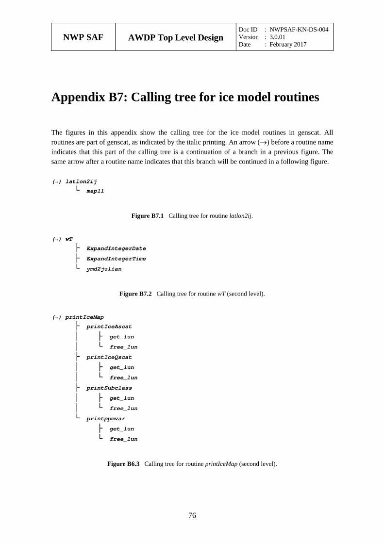
NWP SAF
AWDP Top Level Design Doc ID : NWPSAF-KN-DS-004 Version : 3.0.01 Date : February 2017
76
Appendix B7: Calling tree for ice model routines
The figures in this appendix show the calling tree for the ice model routines in genscat. All routines are part of genscat, as indicated by the italic printing. An arrow (→) before a routine name indicates that this part of the calling tree is a continuation of a branch in a previous figure. The same arrow after a routine name indicates that this branch will be continued in a following figure.
(→) latlon2ij
└ mapll
Figure B7.1 Calling tree for routine latlon2ij.
(→) wT
├ ExpandIntegerDate ├ ExpandIntegerTime └ ymd2julian
Figure B7.2 Calling tree for routine wT (second level).
(→) printIceMap
├ printIceAscat │ ├ get_lun │ └ free_lun ├ printIceQscat │ ├ get_lun │ └ free_lun ├ printSubclass │ ├ get_lun │ └ free_lun └ printppmvar ├ get_lun └ free_lun
Figure B6.3 Calling tree for routine printIceMap (second level).
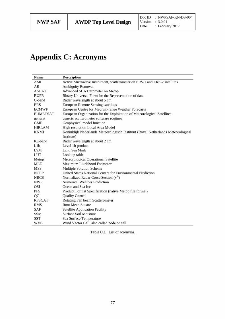
NWP SAF
AWDP Top Level Design Doc ID : NWPSAF-KN-DS-004 Version : 3.0.01 Date : February 2017
77
Appendix C: Acronyms
Name Description AMI Active Microwave Instrument, scatterometer on ERS-1 and ERS-2 satellites AR Ambiguity Removal ASCAT Advanced SCATterometer on Metop BUFR Binary Universal Form for the Representation of data C-band Radar wavelength at about 5 cm ERS European Remote Sensing satellites ECMWF European Centre for Medium-range Weather Forecasts EUMETSAT European Organization for the Exploitation of Meteorological Satellites genscat generic scatterometer software routines GMF Geophysical model function HIRLAM High resolution Local Area Model KNMI Koninklijk Nederlands Meteorologisch Instituut (Royal Netherlands Meteorological
Institute) Ku-band Radar wavelength at about 2 cm L1b Level 1b product LSM Land Sea Mask LUT Look up table Metop Meteorological Operational Satellite MLE Maximum Likelihood Estimator MSS Multiple Solution Scheme NCEP United States National Centers for Environmental Prediction NRCS Normalized Radar Cross-Section (σ 0) NWP Numerical Weather Prediction OSI Ocean and Sea Ice PFS Product Format Specification (native Metop file format) QC Quality Control RFSCAT Rotating Fan beam Scatterometer RMS Root Mean Square SAF Satellite Application Facility SSM Surface Soil Moisture SST Sea Surface Temperature WVC Wind Vector Cell, also called node or cell
Table C.1 List of acronyms.