AV RECEIVER AMPLI-TUNER AUDIO-VIDEO · MANUAL DE INSTRUCCIONES GEBRUIKSAANWIJZING AV RECEIVER...
42
OWNER’S MANUAL MODE D’EMPLOI BEDIENUNGSANLEITUNG BRUKSANVISNING MANUALE DI ISTRUZIONI MANUAL DE INSTRUCCIONES GEBRUIKSAANWIJZING AV RECEIVER AMPLI-TUNER AUDIO-VIDEO RX-V10MKII B G R
Transcript of AV RECEIVER AMPLI-TUNER AUDIO-VIDEO · MANUAL DE INSTRUCCIONES GEBRUIKSAANWIJZING AV RECEIVER...

OWNER’S MANUALMODE D’EMPLOI
BEDIENUNGSANLEITUNGBRUKSANVISNING
MANUALE DI ISTRUZIONIMANUAL DE INSTRUCCIONES
GEBRUIKSAANWIJZING
AV RECEIVER
AMPLI-TUNER AUDIO-VIDEO
RX-V10MKII
B G R
1. To assure the finest performance, please read this manualcarefully. Keep it in a safe place for future reference.
2. Install this unit in a cool, dry, clean place – away fromwindows, heat sources, sources of excessive vibration,dust, moisture and cold. Avoid sources of humming(transformers, motors). To prevent fire or electrical shock,do not expose the unit to rain or water.
3. Never remove the unit cover. Contact your dealer if anobject falls inside the unit.
4. Do not use force on switches, controls or connection wires.When moving the unit, first disconnect the power plug andthe wires connected to other equipment. Never pull on thewires themselves.
5. The openings on the unit cover assure proper ventilation ofthe unit. If these openings are obstructed, the temperatureinside the unit will rise rapidly. Therefore, avoid placingobjects against these openings, and install the unit in awell-ventilated area to prevent fire and damage.
<Europe and U.K. models only>Be sure to allow a space of at least 20 cm behind, 20 cmon the both sides and 30 cm above the top panel of theunit to prevent fire and damage.
6. The voltage used must be the same as that specified onthis unit. Using this unit with a higher voltage thanspecified is dangerous and may result in fire or otheraccidents. YAMAHA will not be held responsible for anydamage resulting from use of this unit with a voltage otherthan specified.
7. Always set the VOLUME control to “0” before starting theaudio source play. Increase the volume gradually to anappropriate level after playback has been started.
8. Do not attempt to clean the unit with chemical solvents;this might damage the finish. Use a clean, dry cloth.
9. Be sure to read the “TROUBLESHOOTING” sectionregarding common operating errors before concluding thatthe unit is faulty.
10. When not planning to use this unit for long periods of time,disconnect the AC power plug from the wall outlet.
11. To prevent lightning damage, disconnect the AC powerplug and antenna cable when there is an electrical storm.
12. Grounding or polarization – Precautions should be takenso that the grounding or polarization of an appliance is notdefeated.
13. Do not connect audio unit to the AC outlet on the rearpanel if the equipment requires more power than the outletis rated to provide.
14. Voltage Selector (General Model only)The voltage selector on the rear panel of this unit mustbe set for your local main voltage BEFORE plugginginto the AC main supply.Voltages are 110/120/220/240 V AC, 50/60 Hz.
This unit is not disconnected from the AC power source aslong as it is connected to the wall outlet, even if this unititself is turned off. This state is called the standby mode.In this mode, this unit is designed to consume a smallamount of power.
IMPORTANTPlease record the serial number of your unit in the spacebelow.
Model:
Serial No.:
The serial number is located on the rear of the unit.Retain this Owner’s Manual in a safe place for futurereference.
WARNINGTO REDUCE THE RISK OF FIRE OR ELECTRIC SHOCK,DO NOT EXPOSE THIS UNIT TO RAIN OR MOISTURE.
FREQUENCY STEP switch (General Model only)Because the interstation frequency spacing differs indifferent areas, set the FREQUENCY STEP switch (locatedat the rear) according to the frequency spacing in your area.Before setting this switch, disconnect the AC power plug ofthis unit from the AC outlet.
For U.K. customersIf the socket outlets in the home are not suitable for the plugsupplied with this appliance, it should be cut off and anappropriate 3 pin plug fitted. For details, refer to theinstructions described below.Note: The plug severed from the mains lead must bedestroyed, as a plug with bared flexible cord is hazardous ifengaged in a live socket outlet.
Special Instructions for U.K. Model
IMPORTANTTHE WIRES IN MAINS LEAD ARE COLOURED INACCORDANCE WITH THE FOLLOWING CODE:
Blue: NEUTRALBrown: LIVE
As the colours of the wires in the mains lead of thisapparatus may not correspond with the coloured markingsidentifying the terminals in your plug, proceed as follows:The wire which is coloured BLUE must be connected to theterminal which is marked with the letter N or colouredBLACK. The wire which is coloured BROWN must beconnected to the terminal which is marked with the letter Lor coloured RED. Making sure that neither core isconnected to the earth terminal of the three pin plug.
2
CAUTION : READ THIS BEFORE OPERATING YOUR UNIT.
3
En
glish
CAUTION ...................................................................2
FEATURES ................................................................4
PROFILE OF THIS UNIT ...........................................5
GETTING STARTED .................................................6
Unpacking ..................................................................6Opening and closing the front cover ...........................6Installing batteries in the remote controller ................7Using the remote controller ........................................7
SPEAKER SET UP ....................................................8
CONNECTIONS .........................................................9
Connecting audio and video components ..................9Connecting speakers ...............................................12Connecting antennas ...............................................14
CONTROLS AND THEIR FUNCTIONS ..................16
Front panel ...............................................................16Remote controller .....................................................18Display panel ............................................................20
SPEAKER BALANCE ADJUSTMENT.....................21
PLAYING AND RECORDING A SOURCE .............24
Playing a source .......................................................24Recording a source to tape (or MD) .........................25Sound control ...........................................................26
BASIC TUNING OPERATION .................................27
Automatic tuning ......................................................27Manual tuning ...........................................................27
PRESET TUNING ....................................................28
Manual preset tuning ................................................28Automatic preset tuning ...........................................29Exchanging preset stations ......................................30
RECEIVING RDS STATIONS <Europe and U. K. models only> .........................31
Displaying RDS data ................................................31Selecting your desired program type fromamong preset RDS stations (PTY SEEK) ................34Automatic selection of desired program when broadcasting starts .........................................35
USING DIGITAL SOUND FIELD PROCESSOR (DSP) ........................................................................36
Brief overview of Digital Sound Field Programs .......36Playing a source with an effect of the digital sound field processor (DSP) ....................................37
TROUBLESHOOTING .............................................40
SPECIFICATIONS ...................................................41
CONTENTS
Thank you for selecting this YAMAHA AV receiver.
4
5 Speaker Configuration (Power Amp. Section)Main: 45W + 45W (8Ω) RMS Output
Power, 0.04% THD, 20–20,000 HzCenter: 45W (8Ω) RMS Output
Power, 0.04% THD, 1 kHzRear: 15W + 15W (8Ω) RMS Output
Power, 0.3% THD, 1 kHz
Digital Sound Field Processor
Dolby Pro Logic Surround Decoder
Theater-like Sound Experience by theCombination of Dolby Pro Logic andYAMAHA DSP Technology (CINEMA DSP)
Automatic Input Balance Control forDolby Pro Logic Surround
Test Tone Generator for Easier SpeakerBalance Adjustment
3 Center Channel Modes(NORMAL/WIDE/PHANTOM)
40-Station Random Access Preset Tuning
Automatic Preset Tuning
Preset Station Shifting Capability (PresetEditing)
IF Count Direct PLL Synthesizer TuningSystem
On Screen Display Function Helpful inControlling This Unit
6-Channel Discrete Input Terminals forConnecting with a Dolby Digital orAnother 5.1-channel Decoder
Video Signal Input/Output Capability
SLEEP Timer
Remote Control Capability
<Europe and U.K. models only> Multi-Functions for RDS Broadcast
Reception
FEATURES

5
En
glish
PROFILE OF THIS UNITYou are the proud owner of a Yamaha stereo receiver –an extremely sophisticated audio component. The Digital Sound FieldProcessor (DSP) built into this unit takes advantage of Yamaha’s undisputed leadership in the field of digital audio processing tobring you a whole new world of listening experiences. Follow the instructions in this manual carefully when setting up your system,and this unit will sonically transform your room into a wide range of listening environments –movie theater, concert hall, and so on.In addition, you get incredible realism from sources encoded with Dolby Surround using the built-in Dolby Pro Logic SurroundDecoder.Please read this operation manual carefully and store it in a safe place for later reference.
Digital Sound Field Processing
Technological advances in sound reproduction over the last 30years have enhanced the listening experience with improvedclarity, precision and power. However, something has still beenmissing: The atmosphere and acoustic ambiance of the publicvenue. Our Yamaha engineers have extensively researchedthe nature of sound acoustics and the way sound reflectsinside a room. We sent these engineers to famous theatersand concert halls around the world to measure the acoustics ofthose venues with sophisticated microphones. The data theycollected is used to recreate these environments in digital
sound fields. Some of these digital sound fields are createdusing data measured directly at the original venue; others arecreated from combinations of data to form uniqueenvironments for specific purposes.
You can use these sound fields to enhance any source and incombination with the Dolby Pro Logic Surround technology.Some are designed especially for music, and some especiallyfor movies.
Dolby Pro Logic Surround
Dolby Pro Logic Surround has been used in movie theaterssince the mid-seventies. It has also been available in homeentertainment systems since the late eighties and continues tobe a popular format for home theater systems. It uses fourdiscrete channels and five speakers to reproduce realistic anddynamic sound effects: two main channels (left and right), acenter channel for dialog, and a rear channel for special soundeffects. The rear channel reproduces sound within a narrowfrequency range. Most video tapes and laser discs include Dolby Pro LogicSurround encoding as do many TV and cable broadcasts. TheDolby Pro Logic Surround decoder built into this unit employs adigital signal processing system that stabilizes each channelfor even more accurate sound positioning than is available withstandard analog processors.
Manufactured under license from Dolby Laboratories LicensingCorporation. DOLBY, the double-D symbol and PRO LOGICare trademarks of Dolby Laboratories Licensing Corporation.
Dolby Pro Logic Surround + DSP
The Dolby Surround sound system shows its full ability in alarge movie theater, because movie sounds are originallydesigned to be reproduced in a large movie theater that uses amultitude of speakers. Trying to create a sound environmentsimilar to that of a movie theater in your home is difficultbecause of the room size, material inside the walls, number ofspeakers, and so on. In other words, your listening room isvery different from a movie theater.However, Yamaha DSP technology allows you to create nearlythe same sound experience as that of a large movie theater inyour home by compensating for the lack of presence anddynamics in the listening room with its original digital soundfields combined with Dolby Surround sound field.
The combination of Dolby Pro Logic Surround and DSP is usedon the sound field program “ PRO LOGIC ENHANCED”.
The YAMAHA “CINEMA DSP” logo indicates these programs thatare created by the combination of Dolby Pro Logic and YAMAHADSP technology.
CINEMA DSP
6
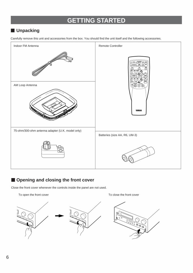
m Opening and closing the front cover
Close the front cover whenever the controls inside the panel are not used.
To open the front cover To close the front cover
Indoor FM Antenna
AM Loop Antenna
75-ohm/300-ohm antenna adapter (U.K. model only)
Remote Controller
Batteries (size AA, R6, UM-3)
m Unpacking
Carefully remove this unit and accessories from the box. You should find the unit itself and the following accessories.
REC/PAUSEDIR BDIR A PLAY
DISC
POWER /I VOLUME
PLAY
DVD/LD2CH/6CH
PRESET A/B/C/D/E– +
LEVELDELAY/CENTER
/REAR/SWFR TEST EFFECT
PROGRAM PROLOGIC ENHANCED
– +
SLEEP
TAPEA/B
ON/OFF
TUNER
CD
PHONO
VCRV-AUX
GETTING STARTED
Remote controller operation range Notes The area between the remote controller and the main unit
must be clear of large obstacles. Do not expose the remote control sensor to strong lighting,
in particular, an inverter type fluorescent lamp. Otherwise,the remote controller may not work properly. If necessary,position the main unit away from direct lighting.
7
En
glish
Since the remote controller will be used for many of this unit’scontrol operations, you should begin by installing the suppliedbatteries.
1.Turn the remote controller over and slide the batterycompartment cover in the direction of the arrow.
2. Insert the batteries (R6, AA, UM-3 type) according to thepolarity markings on the inside of the battery compartment.
3.Close the battery compartment cover.
Battery replacement
If you find that the remote controller must be used closer to themain unit, the batteries are weak. Replace both batteries withnew ones.
Notes Use only AA, R6, UM-3 batteries. Be sure the polarities are correct. (See the illustration inside
the battery compartment.) Remove the batteries if the remote controller is not used for
an extended period of time. If batteries leak, dispose of them immediately. Avoid
touching the leaked material and contact with clothing, etc.Clean the battery compartment thoroughly before installingnew batteries.
1
3
2
30° 30°
Remote controlsensor
Within approximately6 m (19.7 feet)
m Using the remote controller
m Installing batteries in the remote controller
8
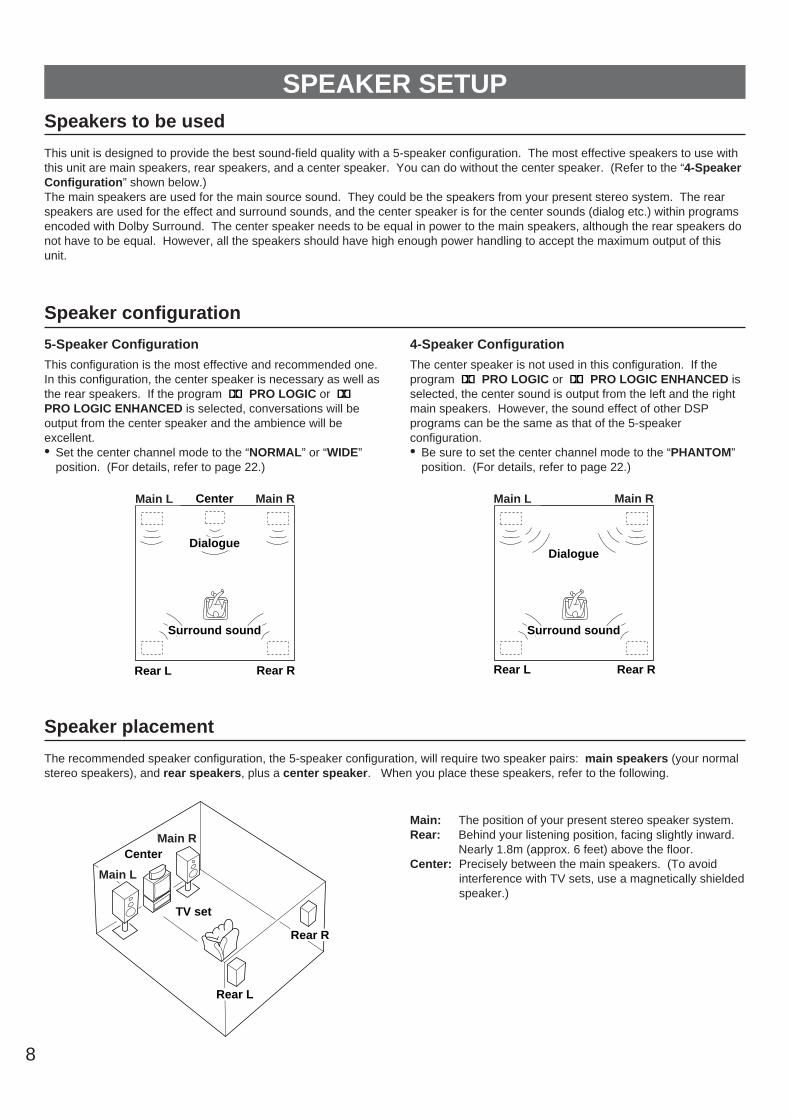
SPEAKER SETUPSpeakers to be used
This unit is designed to provide the best sound-field quality with a 5-speaker configuration. The most effective speakers to use withthis unit are main speakers, rear speakers, and a center speaker. You can do without the center speaker. (Refer to the “4-SpeakerConfiguration” shown below.)The main speakers are used for the main source sound. They could be the speakers from your present stereo system. The rearspeakers are used for the effect and surround sounds, and the center speaker is for the center sounds (dialog etc.) within programsencoded with Dolby Surround. The center speaker needs to be equal in power to the main speakers, although the rear speakers donot have to be equal. However, all the speakers should have high enough power handling to accept the maximum output of thisunit.
Speaker configuration
5-Speaker Configuration
This configuration is the most effective and recommended one.In this configuration, the center speaker is necessary as well asthe rear speakers. If the program PRO LOGIC or PRO LOGIC ENHANCED is selected, conversations will beoutput from the center speaker and the ambience will beexcellent.• Set the center channel mode to the “NORMAL” or “WIDE”
position. (For details, refer to page 22.)
4-Speaker Configuration
The center speaker is not used in this configuration. If theprogram PRO LOGIC or PRO LOGIC ENHANCED isselected, the center sound is output from the left and the rightmain speakers. However, the sound effect of other DSPprograms can be the same as that of the 5-speakerconfiguration.• Be sure to set the center channel mode to the “PHANTOM”
position. (For details, refer to page 22.)
Speaker placement
The recommended speaker configuration, the 5-speaker configuration, will require two speaker pairs: main speakers (your normalstereo speakers), and rear speakers, plus a center speaker. When you place these speakers, refer to the following.
Main: The position of your present stereo speaker system.Rear: Behind your listening position, facing slightly inward.
Nearly 1.8m (approx. 6 feet) above the floor.Center: Precisely between the main speakers. (To avoid
interference with TV sets, use a magnetically shieldedspeaker.)
Front L Center Front R
Dialogue
Surround sound
Dialogue
Surround sound
Rear L Rear R
Front L Front R
Dialogue
Surround sound
Dialogue
Surround sound
Rear L Rear R
Front RCenter
Front L
TV set
Rear R
Rear L
Main L Main RMain L Main R
Main L
Main R
9
En
glish
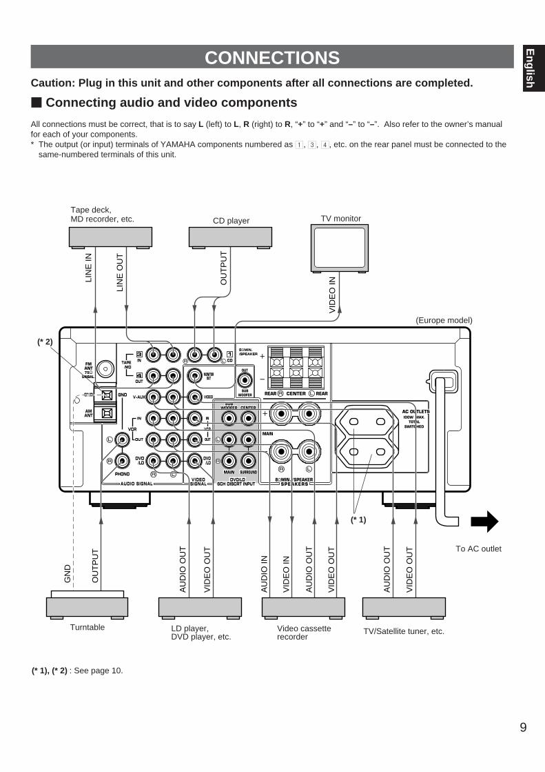
CONNECTIONSCaution: Plug in this unit and other components after all connections are completed.
m Connecting audio and video components
All connections must be correct, that is to say L (left) to L, R (right) to R, “+” to “+” and “–” to “–”. Also refer to the owner’s manualfor each of your components.* The output (or input) terminals of YAMAHA components numbered as 1, 3, 4, etc. on the rear panel must be connected to the
same-numbered terminals of this unit.
(* 1), (* 2) : See page 10.
MONITOROUT
IN
OUT
IN
PHONO
V-AUXGND
IN CD
OUT
GND
FMANT75Ω
UNBAL.
AMANT
DVD/LD
1
OUT
3
4
DVD/LD
I00W MAX.TOTAL
TAPE/MD
VCR
VIDEO
SWITCHED
REAR CENTER REAR
8ΩMIN./SPEAKER
8ΩMIN./SPEAKER
OUT
SUBWOOFER
VIDEOSIGNALAUDIO SIGNAL
VCR
SPEAKERS
SUBWOOFER
MAIN
MAIN
SURROUND
DVD/LD6CH DISCRT INPUT
AC OUTLETSCENTER
VID
EO
IN
GN
D
OU
TP
UT
AU
DIO
OU
T
VID
EO
OU
T
AU
DIO
IN
VID
EO
IN
AU
DIO
OU
T
VID
EO
OU
T
OU
TP
UT
LIN
E O
UT
LIN
E IN
AU
DIO
OU
T
VID
EO
OU
T
(Europe model)
To AC outlet
Tape deck, MD recorder, etc.
Video cassetterecorder
Turntable LD player, DVD player, etc.
CD player TV monitor
TV/Satellite tuner, etc.
(* 2)
(* 1)
10
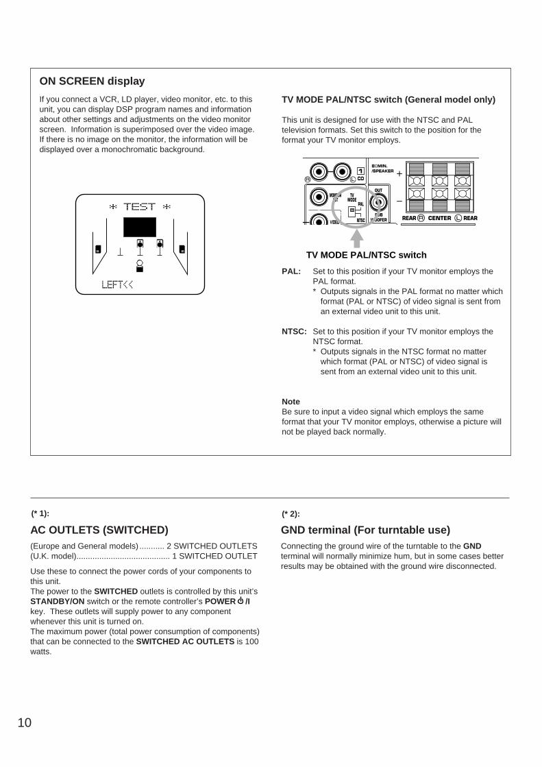
If you connect a VCR, LD player, video monitor, etc. to thisunit, you can display DSP program names and informationabout other settings and adjustments on the video monitorscreen. Information is superimposed over the video image.If there is no image on the monitor, the information will bedisplayed over a monochromatic background.
TV MODE PAL/NTSC switch (General model only)
This unit is designed for use with the NTSC and PALtelevision formats. Set this switch to the position for theformat your TV monitor employs.
PAL: Set to this position if your TV monitor employs thePAL format.* Outputs signals in the PAL format no matter which
format (PAL or NTSC) of video signal is sent froman external video unit to this unit.
NTSC: Set to this position if your TV monitor employs theNTSC format.* Outputs signals in the NTSC format no matter
which format (PAL or NTSC) of video signal issent from an external video unit to this unit.
NoteBe sure to input a video signal which employs the sameformat that your TV monitor employs, otherwise a picture willnot be played back normally.
ON SCREEN display
MONITOROUT
TVMODE
CD1
VIDEO NTSC
PAL
REAR CENTER REAR
8ΩMIN./SPEAKER
OUT
SUBWOOFER
TV MODE PAL/NTSC switch
AC OUTLETS (SWITCHED)(Europe and General models) ........... 2 SWITCHED OUTLETS(U.K. model)......................................... 1 SWITCHED OUTLET
Use these to connect the power cords of your components tothis unit.The power to the SWITCHED outlets is controlled by this unit’sSTANDBY/ON switch or the remote controller’s POWER /Ikey. These outlets will supply power to any componentwhenever this unit is turned on.The maximum power (total power consumption of components)that can be connected to the SWITCHED AC OUTLETS is 100watts.
GND terminal (For turntable use)Connecting the ground wire of the turntable to the GNDterminal will normally minimize hum, but in some cases betterresults may be obtained with the ground wire disconnected.
(* 1): (* 2):
11
En
glish
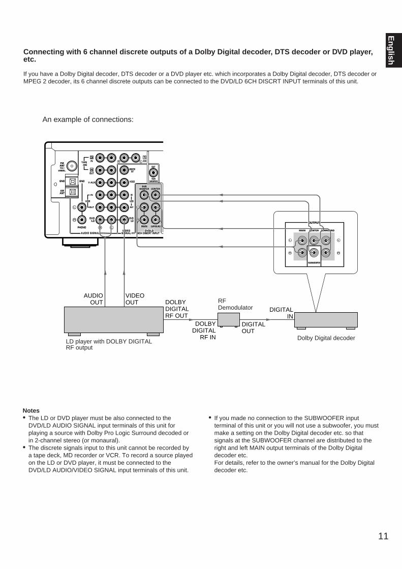
Connecting with 6 channel discrete outputs of a Dolby Digital decoder, DTS decoder or DVD player,etc.
If you have a Dolby Digital decoder, DTS decoder or a DVD player etc. which incorporates a Dolby Digital decoder, DTS decoder orMPEG 2 decoder, its 6 channel discrete outputs can be connected to the DVD/LD 6CH DISCRT INPUT terminals of this unit.
Notes• The LD or DVD player must be also connected to the
DVD/LD AUDIO SIGNAL input terminals of this unit forplaying a source with Dolby Pro Logic Surround decoded orin 2-channel stereo (or monaural).
• The discrete signals input to this unit cannot be recorded bya tape deck, MD recorder or VCR. To record a source playedon the LD or DVD player, it must be connected to theDVD/LD AUDIO/VIDEO SIGNAL input terminals of this unit.
• If you made no connection to the SUBWOOFER inputterminal of this unit or you will not use a subwoofer, you mustmake a setting on the Dolby Digital decoder etc. so thatsignals at the SUBWOOFER channel are distributed to theright and left MAIN output terminals of the Dolby Digitaldecoder etc. For details, refer to the owner’s manual for the Dolby Digitaldecoder etc.
Dolby Digital decoder
RFDemodulator
LD player with DOLBY DIGITAL RF output
An example of connections:
OUTPUT
MAIN CENTER SURROUND
SUBWOOFER
DIGITALIN
DOLBY DIGITALRF OUT
VIDEO OUT
AUDIO OUT
13
MONITOROUT
IN
OUT
IN
PHONO
V-AUXGND
IN CD
OUT
GND
FMANT75Ω
UNBAL.
AMANT
DVD/LD
OUT4
DVD/LD
TAPE/MD
VCR
VIDEO
OUT
SUBWOOFER
VIDEOSIGNALAUDIO SIGNAL
VCR
SUBWOOFER
MAIN
CENTER
SURROUND
DVD/LD6CH DISCRT INPUT
DOLBY DIGITAL
RF IN
DIGITALOUT
12
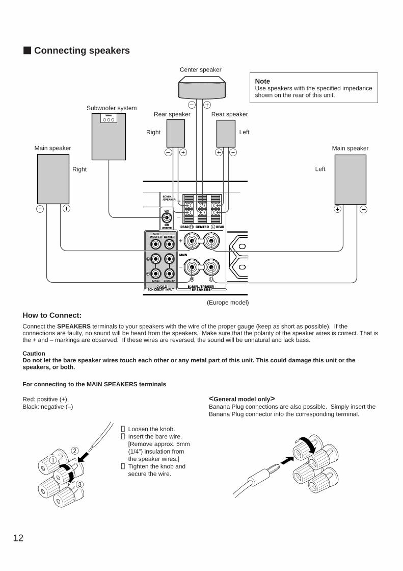
m Connecting speakers
REAR CENTER REAR
8ΩMIN./SPEAKER
OUT
SUBWOOFER
SPEAKERS
SUBWOOFER
MAIN
CENTER
SURROUND
DVD/LD6CH DISCRT INPUT
8ΩMIN./SPEAKER
MAIN
Rear speaker Rear speaker
Center speaker
Main speaker
LeftRight
Subwoofer system
LeftRight
(Europe model)
NoteUse speakers with the specified impedanceshown on the rear of this unit.
For connecting to the MAIN SPEAKERS terminals
Red: positive (+)Black: negative (–)
➀ Loosen the knob.➁ Insert the bare wire.
[Remove approx. 5mm(1/4”) insulation fromthe speaker wires.]
➂ Tighten the knob andsecure the wire.
<General model only>Banana Plug connections are also possible. Simply insert theBanana Plug connector into the corresponding terminal.
12
3
How to Connect:Connect the SPEAKERS terminals to your speakers with the wire of the proper gauge (keep as short as possible). If theconnections are faulty, no sound will be heard from the speakers. Make sure that the polarity of the speaker wires is correct. That isthe + and – markings are observed. If these wires are reversed, the sound will be unnatural and lack bass.
CautionDo not let the bare speaker wires touch each other or any metal part of this unit. This could damage this unit or thespeakers, or both.
Main speaker
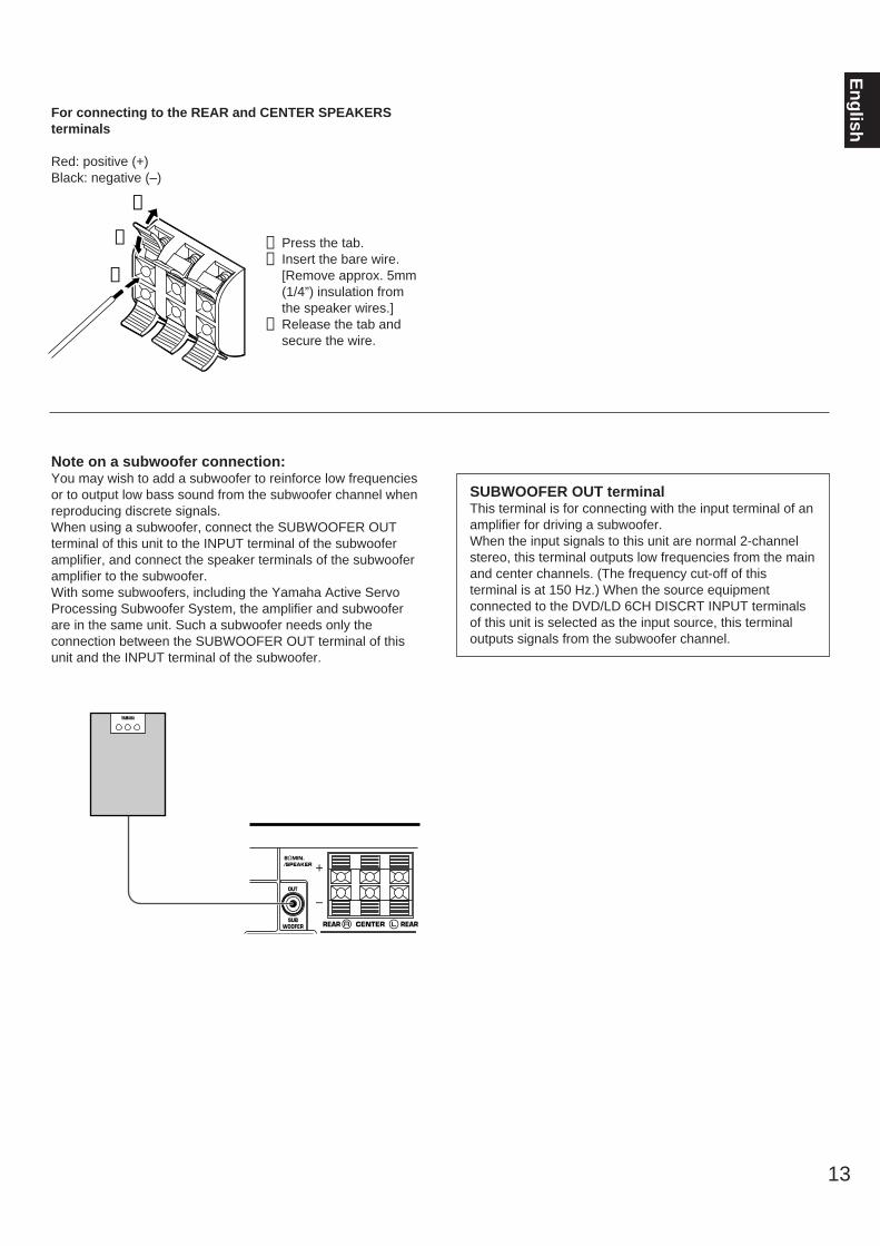
For connecting to the REAR and CENTER SPEAKERSterminals
Red: positive (+)Black: negative (–)
➀ Press the tab.➁ Insert the bare wire.
[Remove approx. 5mm(1/4”) insulation fromthe speaker wires.]
➂ Release the tab andsecure the wire.
13
En
glish
Note on a subwoofer connection:You may wish to add a subwoofer to reinforce low frequenciesor to output low bass sound from the subwoofer channel whenreproducing discrete signals.When using a subwoofer, connect the SUBWOOFER OUTterminal of this unit to the INPUT terminal of the subwooferamplifier, and connect the speaker terminals of the subwooferamplifier to the subwoofer.With some subwoofers, including the Yamaha Active ServoProcessing Subwoofer System, the amplifier and subwooferare in the same unit. Such a subwoofer needs only theconnection between the SUBWOOFER OUT terminal of thisunit and the INPUT terminal of the subwoofer.
SUBWOOFER OUT terminalThis terminal is for connecting with the input terminal of anamplifier for driving a subwoofer.When the input signals to this unit are normal 2-channelstereo, this terminal outputs low frequencies from the mainand center channels. (The frequency cut-off of thisterminal is at 150 Hz.) When the source equipmentconnected to the DVD/LD 6CH DISCRT INPUT terminalsof this unit is selected as the input source, this terminaloutputs signals from the subwoofer channel.
REAR CENTER REAR
OUT
SUBWOOFER
8ΩMIN./SPEAKER
➁
➂
➀
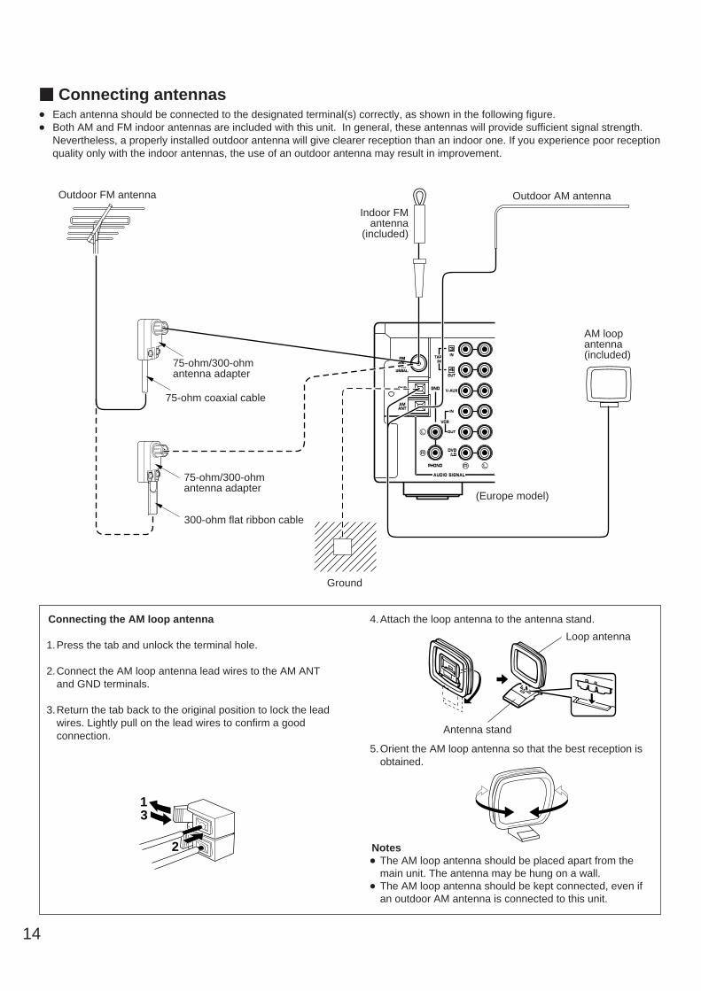
Connecting the AM loop antenna
1.Press the tab and unlock the terminal hole.
2.Connect the AM loop antenna lead wires to the AM ANTand GND terminals.
3.Return the tab back to the original position to lock the leadwires. Lightly pull on the lead wires to confirm a goodconnection.
4.Attach the loop antenna to the antenna stand.
5.Orient the AM loop antenna so that the best reception isobtained.
Notes The AM loop antenna should be placed apart from the
main unit. The antenna may be hung on a wall. The AM loop antenna should be kept connected, even if
an outdoor AM antenna is connected to this unit.
14
m Connecting antennas Each antenna should be connected to the designated terminal(s) correctly, as shown in the following figure. Both AM and FM indoor antennas are included with this unit. In general, these antennas will provide sufficient signal strength.
Nevertheless, a properly installed outdoor antenna will give clearer reception than an indoor one. If you experience poor receptionquality only with the indoor antennas, the use of an outdoor antenna may result in improvement.
IN
PHONO
V-AUXGND
IN
OUT
GND
FMANT75Ω
UNBAL.
AMANT
DVD/LD
OUT
3
4
TAPE/MD
VCR
AUDIO SIGNAL
Outdoor FM antenna
Antenna stand
Loop antenna
Outdoor AM antenna
AM loopantenna(included)
Ground
75-ohm/300-ohmantenna adapter
75-ohm/300-ohmantenna adapter
75-ohm coaxial cable
300-ohm flat ribbon cable
Indoor FMantenna
(included)
(Europe model)
1
2
3
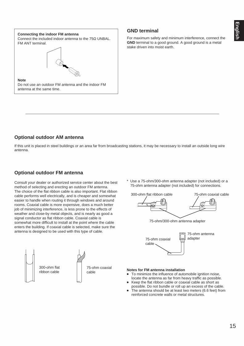
Optional outdoor AM antenna
If this unit is placed in steel buildings or an area far from broadcasting stations, it may be necessary to install an outside long wireantenna.
15
En
glish
Optional outdoor FM antenna
Consult your dealer or authorized service center about the bestmethod of selecting and erecting an outdoor FM antenna.The choice of the flat ribbon cable is also important. Flat ribboncable performs well electrically, and is cheaper and somewhateasier to handle when routing it through windows and aroundrooms. Coaxial cable is more expensive, does a much betterjob of minimizing interference, is less prone to the effects ofweather and close-by metal objects, and is nearly as good asignal conductor as flat ribbon cable. Coaxial cable issomewhat more difficult to install at the point where the cableenters the building. If coaxial cable is selected, make sure theantenna is designed to be used with this type of cable.
* Use a 75-ohm/300-ohm antenna adapter (not included) or a75-ohm antenna adapter (not included) for connections.
300-ohm flat ribbon cable 75-ohm coaxial cable
75-ohm/300-ohm antenna adapter
Notes for FM antenna installation To minimize the influence of automobile ignition noise,
locate the antenna as far from heavy traffic as possible. Keep the flat ribbon cable or coaxial cable as short as
possible. Do not bundle or roll up an excess of the cable. The antenna should be at least two meters (6.6 feet) from
reinforced concrete walls or metal structures.
300-ohm flatribbon cable
75-ohm coaxialcable
75-ohm antennaadapter75-ohm coaxial
cable
Connecting the indoor FM antennaConnect the included indoor antenna to the 75Ω UNBAL.FM ANT terminal.
NoteDo not use an outdoor FM antenna and the indoor FMantenna at the same time.
GND terminalFor maximum safety and minimum interference, connect theGND terminal to a good ground. A good ground is a metalstake driven into moist earth.

1 STANDBY/ON switchPress this switch to turn on the power. Press this switch againto set this unit in the standby mode.
Standby modeThis unit is still using a small amount of power in this modein order to be ready to receive infrared-signals from theremote controller.
2 Remote control sensorReceives signals from the remote controller.
3 Display panelDisplays a variety of information. (Refer to page 20 for details.)
4 INPUT selectorTurn this knob to select the input source.The selected source will be shown on the display.
PTY SELECTOR<Europe and U.K. models only>When this unit is in the PTY SEEK mode, tuning this controlchanges the currently selected program type.
5 VOLUME controlUsed to raise or lower the volume level.
6 Front coverRefer to page 6 on how to open and close the front cover.
7 PHONES jackHeadphones can be plugged into this jack for private listening.Only the sound signals from the main channels are output.When listening with headphones privately, set the SPEAKERSswitch to the OFF position.
8 SPEAKERS switchPress and set this switch inward (ON) to make the all speakersand a subwoofer produce a sound.Press and release this switch outward (OFF) to make the allspeakers and a subwoofer produce no sound.
16
CONTROLS AND THEIR FUNCTIONSm Front panel
SPEAKERS
OFFON
A/B/C/D/EPRESET STATIONS
TUNING KEY MODE
TUNINGMODEFM/AM MEMORY PROGRAM
CENTERMODE
EDIT
AUTO/MAN’L MONO MAN’L/AUTO FM
BASS TREBLE BALANCE0
– +
0
– + L R
INPUTDVD-LD/VCR/V-AUX/TAPE•MD/CD/TUNER/PHONO
VOLUME
0 I0
STANDBY/ON
PHONES
NATURAL SOUND AV RECEIVER RX–V10MK
EON
PTY SEEK
MODE START
PTY SELECTOR
1 2 3
E F
4 5
0AB D6 8 9 C IJ KGH L7
6CH/2CH
CINEMA DSP
RDS MODE/FREQ
Parts in the shaded areas are provided for Europe and U.K. models only.
PHONES
17
En
glish
9 RDS MODE/FREQ button <Europe and U.K. models only>When an RDS station is received, pressing this button changesthe display mode into the PS mode, PTY mode, RT mode, andfrequency display in turn.
0 PTY SEEK MODE button<Europe and U.K. models only>Turns the unit into the PTY SEEK mode.
A PTY SEEK START button<Europe and U.K. models only>Begins searching for a station after the desired program type isselected in the PTY SEEK mode.
B EON button<Europe and U.K. models only>Selects the desired program type (NEWS, INFO, AFFAIRS,SPORT) when you want to call a radio program of the programtype automatically.
C FM/AM buttonPress this button to switch the reception band between FM andAM.
D A/B/C/D/E buttonPress this button to select a group (A to E) of preset stations.
E TUNING MODE (AUTO/MAN’L MONO) buttonPress this button to switch the tuning mode between automaticand manual. To select the automatic tuning mode, press thisbutton so that the “AUTO” indicator is illuminated on thedisplay. To select the manual tuning mode, press this button sothat the “AUTO” indicator is not illuminated.
F MEMORY (MAN’L/AUTO FM) buttonUse this button to enter a station to memory. Refer to thesection “Manual preset tuning” on page 28 for details.Hold down this button for more than 3 seconds to startautomatic preset tuning. Refer to page 29 for details.
G PRESET STATIONS/TUNING buttonThis button is used for the PRESET STATIONS function when“PRESET” is illuminated on the display, and the TUNINGfunction when “PRESET” is not illuminated. The followingexplains these functions in detail.
PRESET STATIONS :Selects a preset station number (from 1 to 8). Press the side to select a higher preset station number.Press the side to select a lower preset station number.
TUNING :Used for tuning. Press the side to tune in to a higherfrequency, and press the side to tune in to a lowerfrequency.
H CENTER MODE buttonSelects a center channel output mode (NORMAL, WIDE orPHANTOM). (For details, refer to page 22.)
I PROGRAM buttonWhen this button is repeatedly pressed, the built-in digitalsound field processor turns on, then the selected DSP programchanges to another program one by one, then the digital soundfield processor turns off, and repeated.
J KEY MODE/EDIT buttonPress this button to alternately illuminate and turn off“PRESET” on the display panel. This button switches thefunction of the PRESET STATIONS/TUNING button.This button is also used to exchange the places of two presetstations with each other.
K Tone controlsThese controls are effective only for the sound from the mainspeakers.BASSUsed to increase or decrease the low frequency response.The 0 position produces flat response.TREBLEUsed to increase or decrease the high frequency response.The 0 position produces flat response.
L BALANCE controlThis knob controls the sound from the main speakers only.The balance of the output volume to the left and right mainspeakers can be adjusted to compensate for sound imbalancescaused by the speaker location or listening room conditions.

18
m Remote controllerThe remote controller provided with this unit is designed to control the most commonly used functions. If the CD player or tape deckis a YAMAHA component with remote control compatibility, this remote controller will also control various functions.
For Control of This Unit
1 DELAY/CENTER/REAR/SWFR and LEVEL +/– keysAdjust the delay time (DELAY), the center channel output level(CENTER), the rear channel output level (REAR) and theoutput level to the SUBWOOFER OUT terminal (SWFR). Select the item which you want to adjust by pressing theDELAY/CENTER/REAR/SWFR key and adjust its time or levelby pressing the LEVEL +/– key.(For details, refer to pages 23, 26, 38 and 39.)
2 Program selector keys
PROGRAM:When the built-in digital sound field processor (including theDolby Pro Logic Surround decoder) is on, this key changes thecurrently selected DSP program each time the right or left sideof this key is pressed.
PROLOGIC:Directly selects the PRO LOGIC program.
ENHANCED:Directly selects the PRO LOGIC ENHANCED program.
3 Tuner keysControl tuners.+: Press this key to select the next preset station number.–: Press this key to select the previous preset station
number.A/B/C/D/E: Selects the group (A to E) of preset station
numbers.
4 SLEEP timer keyThis unit is automatically set in the standby mode one hourafter this key is pressed (so that the “SLEEP” indicator isilluminated). To cancel this function, press this key again sothat the “SLEEP” indicator turns off.
5 POWER /I keyTurns on the power of this unit and sets this unit in the standbymode alternately.
6 VOLUME +/– keysPress these keys to increase or decrease the volume.
REC/PAUSEDIR BDIR A PLAY
DISC
VOLUME
PLAY
DVD/LD2CH/6CH
PRESET A/B/C/D/E– +
LEVELDELAY//CENTER
/REAR/SWFR TEST EFFECT
PROGRAM PROLOGIC ENHANCED
– +
SLEEP
TAPEA/B
ON/OFF
TUNER
CD
PHONO
VCR
1
2
3
4
5
2
8
7
9
6
V-AUX
1
POWER /I
19
En
glish7 Input selector keys
Press a key to select the input source.
When the DVD/LD input source is selected, pressing theDVD/LD key switches the input signals between 2 channelstereo signals and 6 channel discrete signals. When switchedto “6ch”, discrete signals from the unit connected to theDVD/LD 6CH DISCRT INPUT terminals of this unit areselected as the input signals.
8 EFFECT ON/OFF keyPress this key to turn on/off the digital sound field processor,which includes the Dolby Pro Logic Surround decoder.
9 TEST keyThis key is used when adjusting the speaker balance. (Refer topages 21 to 23.)
For Other Component Control
Identify the remote controller keys with your component’s keys.If these keys are identical, their functions will be the same. Oneach key function, refer to the corresponding instruction onyour component’s manual.
1 Tape deck keysControl tape decks.* The DIR A, B and A/B keys apply only to double cassette
tape decks.* Pressing the DIR A key will reverse the tape direction on a
single cassette tape deck with the automatic reversefunction.
2 CD player keysControl compact disc players.* The DISC is used for compact disc changers.

20
m Display panel
1 AUTO indicatorThis indicator will be illuminated during the automatic tuningmode.
2 MEMO indicatorA flashing MEMO indicator means a station can be saved, asexplained in the following:Press the MEMORY button. The MEMO indicator will flashabout 5 seconds. While the indicator is flashing, program thedisplayed station to memory by using the A/B/C/D/E andPRESET STATIONS/TUNING buttons.
3 Preset station number indicatorShows the selected group (A to E) and preset station number(1 to 8).
4 Multi-information displayThis display shows the status of adjustments and settingchanges. Several statuses can be viewed at one time. Thecurrent station frequency and band (AM or FM) will alsoappear when the tuner source input mode is selected.
5 STEREO indicatorThis indicator will be illuminated when an FM stereo broadcastwith sufficient signal strength is received.
6 Signal-level meterIndicates the signal level of the received station.If multipath interference is detected, the indication decreases.
7 PTY H (HOLD) indicator<Europe and U.K. models only>This indicator will be illuminated while the search is performedin the PTY SEEK mode.
8 RDS mode indicators<Europe and U.K. models only>The name(s) of RDS mode(s) employed by the currentlyreceived RDS station will be illuminated. Illumination of theindicator on the head of a name shows that the correspondingRDS mode is now selected.
9 EON indicator<Europe and U.K. models only>This indicator will be illuminated when an RDS station thatemploys the EON data service is received.
0 Program type name indicators<Europe and U.K. models only>The name selected in the EON mode will be illuminated.
A DSP program indicatorsThe name of the selected DSP program will be illuminatedwhen the built-in digital sound field processor or the Dolby ProLogic Surround decoder, or both of them are on.
B Center channel mode indicatorsThe name of the selected center channel mode (NORMAL,WIDE or PHANTOM) will be illuminated only when the
PRO LOGIC or PRO LOGIC ENHANCED program isselected.
C TEST indicatorFlashes when the built-in test tone generator is functioning(when the test-tone is output from speakers).
D SLEEP indicatorThis indicator will be illuminated when the built-in SLEEP timeris functioning.
1 2 3 4 5 6
789 < A B C D
TEST
PRESETMEMOAUTOPTY H PTY PS RTEON INFO SPORTNEWS AFFAIRS
ST
0MHz l00FMSLEEPWIDENORMAL
PHANTOMCONCERT
HALLCONCERT
VIDEOPRO LOGICENHANCED
ROCKCONCERT
MONOMOVIE
Indicators in the shaded areas are provided for Europe and U.K. models only.
21
En
glish
1
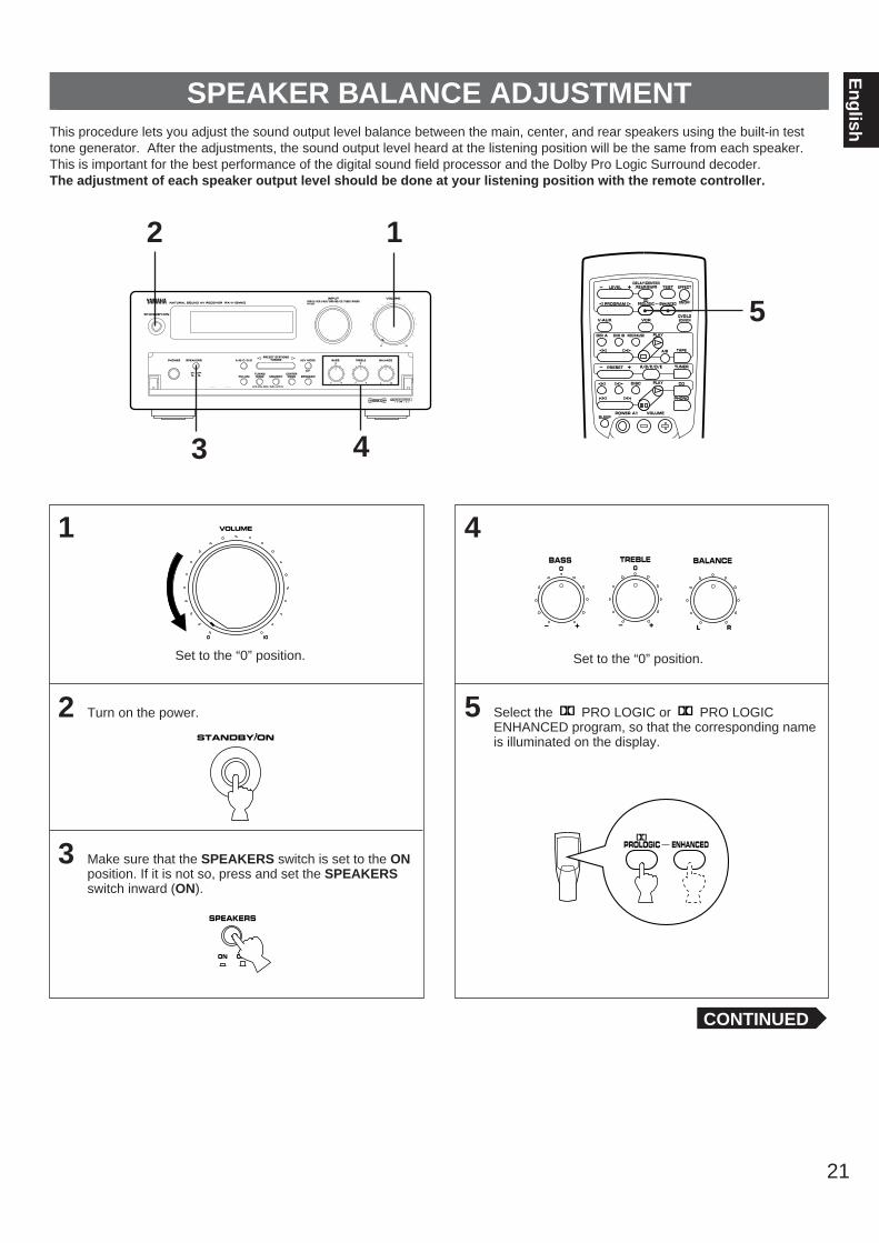
Set to the “0” position.
2 Turn on the power.
3 Make sure that the SPEAKERS switch is set to the ONposition. If it is not so, press and set the SPEAKERSswitch inward (ON).
4
Set to the “0” position.
5 Select the PRO LOGIC or PRO LOGICENHANCED program, so that the corresponding nameis illuminated on the display.
SPEAKER BALANCE ADJUSTMENTThis procedure lets you adjust the sound output level balance between the main, center, and rear speakers using the built-in testtone generator. After the adjustments, the sound output level heard at the listening position will be the same from each speaker.This is important for the best performance of the digital sound field processor and the Dolby Pro Logic Surround decoder.The adjustment of each speaker output level should be done at your listening position with the remote controller.
BASS0
– +
TREBLE0
– +
BALANCE
L R
VOLUME
0 I0
SPEAKERS
OFFON
2 1
3
STANDBY/ON
SPEAKERS
OFFON
A/B/C/D/EPRESET STATIONS
TUNING
PTY SELECTOR
KEY MODE
TUNINGMODEFM/AM MEMORY PROGRAM
CENTERMODE
EDIT
AUTO/MAN’L MONO MAN’L/AUTO FM
BASS TREBLE BALANCE0
– +
0
– + L R
INPUTDVD-LD/VCR/V-AUX/TAPE•MD/CD/TUNER/PHONO
VOLUME
0 I0
STANDBY/ON
PHONES
NATURAL SOUND AV RECEIVER RX–V10MK
EON
PTY SEEK
MODE START
6CH/2CH
CINEMA DSP
RDS MODE/FREQ
4
CONTINUED
PROLOGIC ENHANCED
REC/PAUSEDIR BDIR A PLAY
DISC
VOLUME
PLAY
DVD/LD2CH/6CH
PRESET A/B/C/D/E– +
LEVELDELAY/CENTER
/REAR/SWFR TEST EFFECT
PROGRAM PROLOGIC ENHANCED
– +
SLEEP
TAPEA/B
ON/OFF
TUNER
CD
PHONO
VCRV-AUX
POWER /I
5
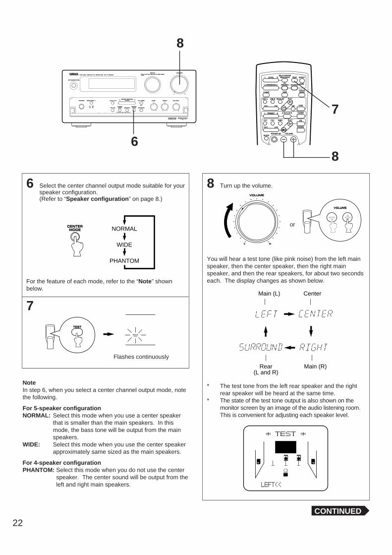
6 Select the center channel output mode suitable for yourspeaker configuration.(Refer to “Speaker configuration” on page 8.)
For the feature of each mode, refer to the “Note” shownbelow.
7
NoteIn step 6, when you select a center channel output mode, notethe following.
For 5-speaker configurationNORMAL: Select this mode when you use a center speaker
that is smaller than the main speakers. In thismode, the bass tone will be output from the mainspeakers.
WIDE: Select this mode when you use the center speakerapproximately same sized as the main speakers.
For 4-speaker configurationPHANTOM: Select this mode when you do not use the center
speaker. The center sound will be output from theleft and right main speakers.
8 Turn up the volume.
You will hear a test tone (like pink noise) from the left mainspeaker, then the center speaker, then the right mainspeaker, and then the rear speakers, for about two secondseach. The display changes as shown below.
* The test tone from the left rear speaker and the rightrear speaker will be heard at the same time.
* The state of the test tone output is also shown on themonitor screen by an image of the audio listening room.This is convenient for adjusting each speaker level.
Main (L)
Rear(L and R)
Center
Main (R)
22
VOLUME
0 I0
CENTERMODE NORMAL
WIDE
PHANTOM
CONTINUED
8
SPEAKERS
OFFON
A/B/C/D/EPRESET STATIONS
TUNING
PTY SELECTOR
KEY MODE
TUNINGMODEFM/AM MEMORY PROGRAM
CENTERMODE
EDIT
AUTO/MAN’L MONO MAN’L/AUTO FM
BASS TREBLE BALANCE0
– +
0
– + L R
INPUTDVD-LD/VCR/V-AUX/TAPE•MD/CD/TUNER/PHONO
VOLUME
0 I0
STANDBY/ON
PHONES
NATURAL SOUND AV RECEIVER RX–V10MK
EON
PTY SEEK
MODE START
6CH/2CH
CINEMA DSP
RDS MODE/FREQ
6
or
VOLUME
REC/PAUSEDIR BDIR A PLAY
DISC
VOLUME
PLAY
DVD/LD2CH/6CH
PRESET A/B/C/D/E– +
LEVELDELAY/CENTER
/REAR/SWFR TEST EFFECT
PROGRAM PROLOGIC ENHANCED
– +
SLEEP
TAPEA/B
ON/OFF
TUNER
CD
PHONO
VCRV-AUX
POWER /I
8
7
TEST
TEST
Flashes continuously
23
En
glish
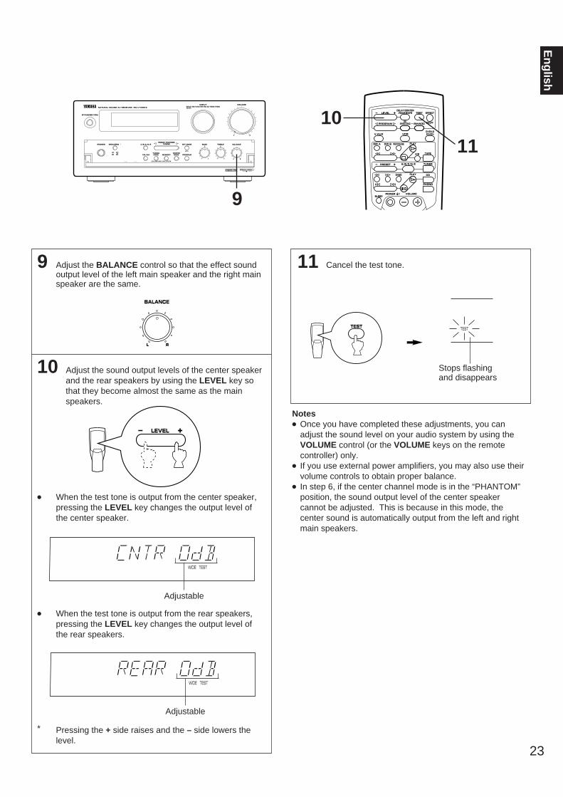
9 Adjust the BALANCE control so that the effect soundoutput level of the left main speaker and the right mainspeaker are the same.
10 Adjust the sound output levels of the center speakerand the rear speakers by using the LEVEL key sothat they become almost the same as the mainspeakers.
When the test tone is output from the center speaker,pressing the LEVEL key changes the output level ofthe center speaker.
When the test tone is output from the rear speakers,pressing the LEVEL key changes the output level ofthe rear speakers.
* Pressing the + side raises and the – side lowers thelevel.
11 Cancel the test tone.
Notes Once you have completed these adjustments, you can
adjust the sound level on your audio system by using theVOLUME control (or the VOLUME keys on the remotecontroller) only.
If you use external power amplifiers, you may also use theirvolume controls to obtain proper balance.
In step 6, if the center channel mode is in the “PHANTOM”position, the sound output level of the center speakercannot be adjusted. This is because in this mode, thecenter sound is automatically output from the left and rightmain speakers.
Stops flashing and disappears
TEST
BALANCE
L R
TEST
SPEAKERS
OFFON
A/B/C/D/EPRESET STATIONS
TUNING
PTY SELECTOR
KEY MODE
TUNINGMODEFM/AM MEMORY PROGRAM
CENTERMODE
EDIT
AUTO/MAN’L MONO MAN’L/AUTO FM
BASS TREBLE BALANCE0
– +
0
– + L R
INPUTDVD-LD/VCR/V-AUX/TAPE•MD/CD/TUNER/PHONO
VOLUME
0 I0
STANDBY/ON
PHONES
NATURAL SOUND AV RECEIVER RX–V10MK
EON
PTY SEEK
MODE START
6CH/2CH
CINEMA DSP
RDS MODE/FREQ
9
REC/PAUSEDIR BDIR A PLAY
DISC
VOLUME
PLAY
DVD/LD2CH/6CH
PRESET A/B/C/D/E– +
LEVELDELAY/CENTER
/REAR/SWFR TEST EFFECT
PROGRAM PROLOGIC ENHANCED
– +
SLEEP
TAPEA/B
ON/OFF
TUNER
CD
PHONO
VCRV-AUX
POWER /I
11
10
TESTWIDE
TESTWIDE
LEVEL– +
Adjustable
Adjustable
24
1
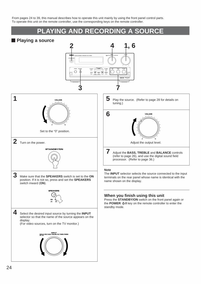
Set to the “0” position.
2 Turn on the power.
3 Make sure that the SPEAKERS switch is set to the ONposition. If it is not so, press and set the SPEAKERSswitch inward (ON).
4 Select the desired input source by turning the INPUTselector so that the name of the source appears on thedisplay.(For video sources, turn on the TV monitor.)
5 Play the source. (Refer to page 28 for details ontuning.)
6
Adjust the output level.
7 Adjust the BASS, TREBLE and BALANCE controls(refer to page 26), and use the digital sound fieldprocessor. (Refer to page 36.)
NoteThe INPUT selector selects the source connected to the inputterminals on the rear panel whose name is identical with thename shown on the display.
When you finish using this unitPress the STANDBY/ON switch on the front panel again orthe POWER /I key on the remote controller to enter thestandby mode.
PLAYING AND RECORDING A SOURCEm Playing a source
VOLUME
0 I0
VOLUME
0 I0
SPEAKERS
OFFON
1, 62
3
SPEAKERS
OFFON
A/B/C/D/EPRESET STATIONS
TUNING
PTY SELECTOR
KEY MODE
TUNINGMODEFM/AM MEMORY PROGRAM
CENTERMODE
EDIT
AUTO/MAN’L MONO MAN’L/AUTO FM
BASS TREBLE BALANCE0
– +
0
– + L R
INPUTDVD-LD/VCR/V-AUX/TAPE•MD/CD/TUNER/PHONO
VOLUME
0 I0
STANDBY/ON
PHONES
NATURAL SOUND AV RECEIVER RX–V10MK
EON
PTY SEEK
MODE START
6CH/2CH
CINEMA DSP
RDS MODE/FREQ
4
From pages 24 to 39, this manual describes how to operate this unit mainly by using the front panel control parts.To operate this unit on the remote controller, use the corresponding keys on the remote controller.
7
PTY SELECTOR
INPUTDVD-LD/VCR/V-AUX/TAPEzMD/CD/TUNER/PHONO6CH / 2CH
STANDBY/ON

25
En
glish
To listen to a decoded source using DolbyDigital or DTS by reproducing the signals inputto the DVD/LD 6CH DISCRT INPUT terminals ofthis unit.
In step 4, turn the INPUT selector on the front panel or pressthe DVD/LD (2CH/6CH) key on the remote controllerrepeatedly until “DVD 6ch” appears on the display.
To cancel listening to a decoded source using DolbyDigital or DTSSelect another input source.
Note for reproducing discrete signals with Dolby Digital orDTS decoded:1. Your speaker system must include a center speaker.2. Your speaker system may include a subwoofer.
* Connect a subwoofer which has a built-in amplifier to theSUBWOOFER OUT terminal of this unit.
* You can do without using a subwoofer. If you do so, youmust set the Dolby Digital Decoder etc. so that signals atthe subwoofer channel are distributed to the right and leftMAIN output terminals. For details, refer to the owner’s manual for the DolbyDigital Decoder etc.
Notes When you switch to the “6ch” mode, the built-in Digital
Sound Field processor will not work and adjustment of delaytime cannot be made.
Switching this unit to the “6ch” mode will input no signal tothis unit if there is no connection to the DVD/LD 6CHDISCRT INPUT terminals of this unit.
m Recording a source to tape (or MD)
DVD/LD2CH/6CH
or
Press once or twice.
2
SPEAKERS
OFFON
A/B/C/D/EPRESET STATIONS
TUNING
PTY SELECTOR
KEY MODE
TUNINGMODEFM/AM MEMORY PROGRAM
CENTERMODE
EDIT
AUTO/MAN’L MONO MAN’L/AUTO FM
BASS TREBLE BALANCE0
– +
0
– + L R
INPUTDVD-LD/VCR/V-AUX/TAPE•MD/CD/TUNER/PHONO
VOLUME
0 I0
STANDBY/ON
PHONES
NATURAL SOUND AV RECEIVER RX–V10MK
EON
PTY SEEK
MODE START
6CH/2CH
CINEMA DSP
RDS MODE/FREQ
1
1 Select the source to be recorded.
2 Play the source and then turn the VOLUME control upto confirm the input source. (Refer to the page 27 fordetails on tuning.)
3 Begin recording to the tape deck (or MD recorder etc.)or VCR connected to this unit.
Notes The settings of DSP and the VOLUME, BASS, TREBLE
and BALANCE controls have no effect on the materialbeing recorded.
In step 1, do not make an input source selection so that“DVD 6ch” appears in the display. Signals input to thisunit’s DVD/LD 6CH DISCRT INPUT terminals cannot berecorded by a tape deck (or MD recorder) or VCR.
VOLUME
0 I0
PTY SELECTOR
INPUTDVD-LD/VCR/V-AUX/TAPEzMD/CD/TUNER/PHONO6CH / 2CH
PTY SELECTOR
INPUTDVD-LD/VCR/V-AUX/TAPEzMD/CD/TUNER/PHONO6CH / 2CH

26
Adjusting the BALANCE control
Adjust the balance of the output volume to the left and rightspeakers to compensate for sound imbalance caused byspeaker location or listening room conditions.
NoteThis control is effective only for the sound from the mainspeakers.
Adjusting the BASS and TREBLE controls
BASS : Turn this knob clockwise to increase (or counter-clockwise to decrease) the low frequency response.
TREBLE : Turn this knob clockwise to increase (or counter-clockwise to decrease) the high frequency response.
NoteThese controls are effective only for the sound from the mainspeakers.
Adjusting the subwoofer output level
If your audio system includes a subwoofer, and an amplifierdriving the subwoofer (or a subwoofer system including anamplifier) is connected to the SUBWOOFER OUT terminal onthe rear of this unit, you can adjust the subwoofer output levelon this unit.Adjustment can be made only by using the remote controller.
1 Press the DELAY/CENTER/REAR/SWFR key repeteadlyuntil “SWFR” appears in the display.
2 By continuously pressing the “+” or “–” side of the LEVELbutton, the level value changes continuously.If you feel that bass tone is insufficient, increase the level,and if you feel that bass tone is overly emphasized,decrease the level.
Control range: MIN, –20 to 0 dB
DELAY/CENTER/REAR/SWFR
LEVEL– +
Adjustable
BALANCE
L R
BASS TREBLE0
– +
0
– +
m Sound control
SPEAKERS
OFFON
A/B/C/D/EPRESET STATIONS
TUNING
PTY SELECTOR
KEY MODE
TUNINGMODEFM/AM MEMORY PROGRAM
CENTERMODE
EDIT
AUTO/MAN’L MONO MAN’L/AUTO FM
BASS TREBLE BALANCE0
– +
0
– + L R
INPUTDVD-LD/VCR/V-AUX/TAPE•MD/CD/TUNER/PHONO
VOLUME
0 I0
STANDBY/ON
PHONES
NATURAL SOUND AV RECEIVER RX–V10MK
EON
PTY SEEK
MODE START
6CH/2CH
CINEMA DSP
RDS MODE/FREQ
27
En
glish
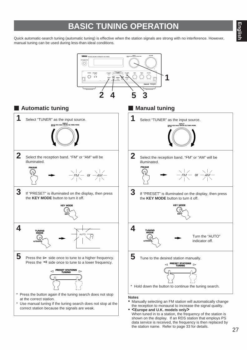
1 Select “TUNER” as the input source.
2 Select the reception band. “FM” or “AM” will beilluminated.
3 If “PRESET” is illuminated on the display, then pressthe KEY MODE button to turn it off.
4
5 Press the side once to tune to a higher frequency.Press the side once to tune to a lower frequency.
* Press the button again if the tuning search does not stopat the correct station.
* Use manual tuning if the tuning search does not stop at thecorrect station because the signals are weak.
1 Select “TUNER” as the input source.
2 Select the reception band. “FM” or “AM” will beilluminated.
3 If “PRESET” is illuminated on the display, then pressthe KEY MODE button to turn it off.
4
5 Tune to the desired station manually.
* Hold down the button to continue the tuning search.
BASIC TUNING OPERATIONQuick automatic-search tuning (automatic tuning) is effective when the station signals are strong with no interference. However,manual tuning can be used during less-than-ideal conditions.
Notes• Manually selecting an FM station will automatically change
the reception to monaural to increase the signal quality.• <Europe and U.K. models only>
When tuned in to a station, the frequency of the station isshown on the display. If an RDS station that employs PSdata service is received, the frequency is then replaced bythe station name. Refer to page 33 for details.
m Automatic tuning m Manual tuning
TUNINGMODE
AUTO/MAN’L MONO
TUNINGMODE
AUTO/MAN’L MONO
PRESET STATIONSTUNING
PRESET STATIONSTUNING
Turn the “AUTO”indicator off.
2 4 35
1
FM/AM
or AMFM
PTY SELECTOR
INPUTDVD-LD/VCR/V-AUX/TAPEzMD/CD/TUNER/PHONO6CH / 2CH
PTY SELECTOR
INPUTDVD-LD/VCR/V-AUX/TAPEzMD/CD/TUNER/PHONO6CH / 2CH
AUTO
FM/AM
or AMFM
KEY MODE
EDIT
KEY MODE
EDIT

1 Tune in to a station.(Refer to the previous page for the tuning procedure.)
2
3 Select a group (A to E) of preset stations before the“MEMO” indicator goes off. The group will appear on thedisplay.
4 Select a preset station number (1 to 8) where you wantto program the station before the “MEMO” indicator goesoff.
5 Press the MEMORY button before the “MEMO” indicator goes off.
* In the same way, program other stations to A2, A3 ... A8.* You can program more stations to preset station numbers
of other groups in the same way by selecting other groupsin step 3.
11 Select the group of preset stations.
22 “PRESET” must be illuminated on the display to recallpreset stations. If necessary, press the KEY MODEbutton.
33 Select the preset station number.
Notes• A new setting can be programmed in place of the former
one.• For presets, the setting of the reception mode (stereo or
monaural) is stored along with the station frequency.
Memory back-upThe memory back-up circuit prevents the programmed datafrom being lost even if this unit is set to the standby mode orthe power plug is disconnected from the AC outlet or thepower is cut due to a temporary power failure. If, however,the power is cut for more than one week, the memory may bedeleted. If so, it can be re-programmed by simply followingthe PRESET TUNING steps.28
PRESET STATIONSTUNING
m Manual preset tuningThis unit can store station frequencies selected by the tuning operation. With this function, you can recall any desired station only byselecting the preset station number. Up to 40 stations (8 stations x 5 groups) can be stored.
PRESET TUNING
To store stations To recall a preset station4, 332, 53, 11 22
MEMORY
MAN’L/AUTO FM
MEMORY
MAN’L/AUTO FM
PRESETMEMOAUTO
A/B/C/D/E PRESETMEMOAUTO
Flashes on and off forabout 5 seconds.
PRESET
0MHz l00FM
Shows the displayed station has been programmed to A1.
SPEAKERS
OFFON
A/B/C/D/EPRESET STATIONS
TUNING
PTY SELECTOR
KEY MODE
TUNINGMODEFM/AM MEMORY PROGRAM
CENTERMODE
EDIT
AUTO/MAN’L MONO MAN’L/AUTO FM
BASS TREBLE BALANCE0
– +
0
– + L R
INPUTDVD-LD/VCR/V-AUX/TAPE•MD/CD/TUNER/PHONO
VOLUME
0 I0
STANDBY/ON
PHONES
NATURAL SOUND AV RECEIVER RX–V10MK
EON
PTY SEEK
MODE START
6CH/2CH
CINEMA DSP
RDS MODE/FREQ
PRESET STATIONSTUNING
A/B/C/D/E
PRESET
KEY MODE
EDIT

29
En
glish
1
2
The automatic preset tuning begins from A1. Receivedstations are programmed to A1, A2 ... A8 sequentially.* If more than 8 stations are received, they are also
programmed to the preset station numbers on other groups (B, C, D and E) in that order.
When the automatic preset tuning is finishedThe display shows the frequency of the last preset station.Check the contents and the number of preset stations byfollowing the procedure of the section “To recall a presetstation” on page 28.
To recall a preset stationSimply follow the procedure of the section “To recall a presetstation” on page 28.* <Europe and U.K. models only>
A recalled station is shown by the frequency or station nameon the display.
Notes• You can replace a preset station by another FM or AM
station manually by simply following the procedure of thesection “To store stations” on page 28.
<General model only>• If the number of received stations is not enough to be stored
up to E8, the search will be finished automatically aftersearching all frequencies.
• With this function, only FM stations with sufficient signalstrength are stored automatically. If the station you want toprogram is weak in signal strength, tune to it in monauralmanually and program it by following the procedure of thesection “To store stations” on page 28.
<Europe and U.K. models only>• The automatic preset tuning search is performed through all
RDS network frequencies until stations are stored up to E8.If the number of received stations is not enough to be storedup to E8, the search will be finished automatically aftersearching all frequencies.
• With this function, only RDS stations with sufficient signalstrength are stored automatically. If the station you want toprogram is weak in signal strength, tune to it in monauralmanually and program it by following the procedure of thesection “To store stations” on page 28.* There may be a case that this function cannot receive a
station which could be received by the automatic tuningmethod. This is because this function receives a largevolume of PI (Program Identification) data along with thestation.
m Automatic preset tuning
You can make use of an automatic preset tuning function for FM stations. With this function, this unit performs automatic tuning andstores FM stations with strong signals sequentially. Up to 40 stations are stored automatically in the same way as in the manualpreset tuning method on page 28.* <Europe and U.K. models only>
Only RDS stations can be stored by this function.
To store stations
Press and hold forabout 3 seconds.
MEMORY
MAN’L/AUTO FM
Flashes.
PRESETMEMOAUTO
1 2
SPEAKERS
OFFON
A/B/C/D/EPRESET STATIONS
TUNING
PTY SELECTOR
KEY MODE
TUNINGMODEFM/AM MEMORY PROGRAM
CENTERMODE
EDIT
AUTO/MAN’L MONO MAN’L/AUTO FM
BASS TREBLE BALANCE0
– +
0
– + L R
INPUTDVD-LD/VCR/V-AUX/TAPE•MD/CD/TUNER/PHONO
VOLUME
0 I0
STANDBY/ON
PHONES
NATURAL SOUND AV RECEIVER RX–V10MK
EON
PTY SEEK
MODE START
6CH/2CH
CINEMA DSP
RDS MODE/FREQ
FM/AM
FM
30
1 Recall the preset station on E1 (by following the methodof “To recall a preset station” on page 28).
2
3 Recall the preset station on A5 by following the samemethod as in step 1.
4
Shows the exchange of stations is completed.
(Example)If you want to exchange the preset stations on E1 and A5 witheach other.
m Exchanging preset stationsYou can exchange the places of two preset stations with each other as shown below.(Example)
Flashes.
Flashes.
KEY MODE
EDIT
KEY MODE
EDIT
PRESETMEMOAUTO
PRESETMEMOAUTO
2, 4
SPEAKERS
OFFON
A/B/C/D/EPRESET STATIONS
TUNING
PTY SELECTOR
KEY MODE
TUNINGMODEFM/AM MEMORY PROGRAM
CENTERMODE
EDIT
AUTO/MAN’L MONO MAN’L/AUTO FM
BASS TREBLE BALANCE0
– +
0
– + L R
INPUTDVD-LD/VCR/V-AUX/TAPE•MD/CD/TUNER/PHONO
VOLUME
0 I0
STANDBY/ON
PHONES
NATURAL SOUND AV RECEIVER RX–V10MK
EON
PTY SEEK
MODE START
6CH/2CH
CINEMA DSP
RDS MODE/FREQ
Press and hold forabout 3 seconds.

31
En
glish
In areas where RDS broadcasts cannot be received, the RDS broadcast functions do not operate. (Skip the procedures from pages31 to 35.)
The following four modes are available in this unit fordisplaying RDS data.
PS (Program Service name) mode:Displays the name of the RDS station now being receivedinstead of the frequency.
PTY (Program Type) mode:Displays the type of the program on the RDS station now beingreceived. There are 15 program types for classifying RDSstations. Refer to the next page for details.
RT (Radio Text) mode:Displays information about the program (such as the title of thesong, name of the singer, etc.) on the RDS station now beingreceived.
EON (Enhanced Other Networks)mode:Select a program type with the EON button. The unit willautomatically change to a station that starts to broadcast thattype of program. When the program is finished, the unit willreturn to the original program.
AUTO
PTY PS RTEON SPORT
ST
0 l00
RECEIVING RDS STATIONSEurope and U.K. models only
RDS (Radio Data System) is a data transmission system gradually being introduced by FM stations in many countries. Stationsusing this system transmit an inaudible stream of data in addition to the normal radio signal.RDS data contains various information, such as PI (Program Identification), PS (Program Service name), PTY (Program Type), RT(Radio Text), EON (Enhanced Other Networks), etc.RDS function is carried out among the network stations.* This unit utilizes PS, PTY, RT and EON to receive RDS broadcast stations.
m Displaying RDS data
32
News:Short accounts of facts, events and publiclyexpressed views, reportage and actuality.
Current affairs:Topical program expanding or enlargingupon the news, generally in differentpresentation style or concept, includingdocumentary debate, or analysis.
Information:Program whose purpose is to impart advicein the widest sense, including meteorologicalreports and forecasts, consumer affairs,medical help, etc.
Sport:Program concerned with any aspect of sport.
Education:Program intended primarily to educate, ofwhich the formal element is fundamental.
Drama:All radio plays and serials.
Culture:Programs concerned with any aspect ofnational or regional culture, includingreligious affairs, philosophy, social science,language, theatre, etc.
Science:Programs about the natural sciences andtechnology.
Varied:Used for mainly speech-based programsusually of light-entertainment nature, notcovered by above categories. Examples are:quizzes, panel games, personality interviews,comedy and satire.
Pop:Commercial music, which would generally beconsidered to be of current popular appeal,often featuring in current or recent recordsales charts.
Rock:Contemporary modern music, usually writtenand performed by young musicians.
M.O.R.:(Middle of the Road Music). Common term todescribe music considered to be “easy-listening”, as opposed to Pop, Rock orClassical. Music in this category is often butnot always, vocal, and usually of shortduration (< 5 min.)
Light classics:Classical Musical for general, rather thanspecialist appreciation. Examples of music inthis category are instrumental music, andvocal or choral works.
Serious classics:Performances of major orchestral works,symphonies, chamber music etc., andincluding Grand Opera.
Other music:Musical styles not fitting into any of the abovecategories. Particularly used for specialistmusic, of which Jazz, Rhythm & Blues, Folk,Country, and Reggae are examples.
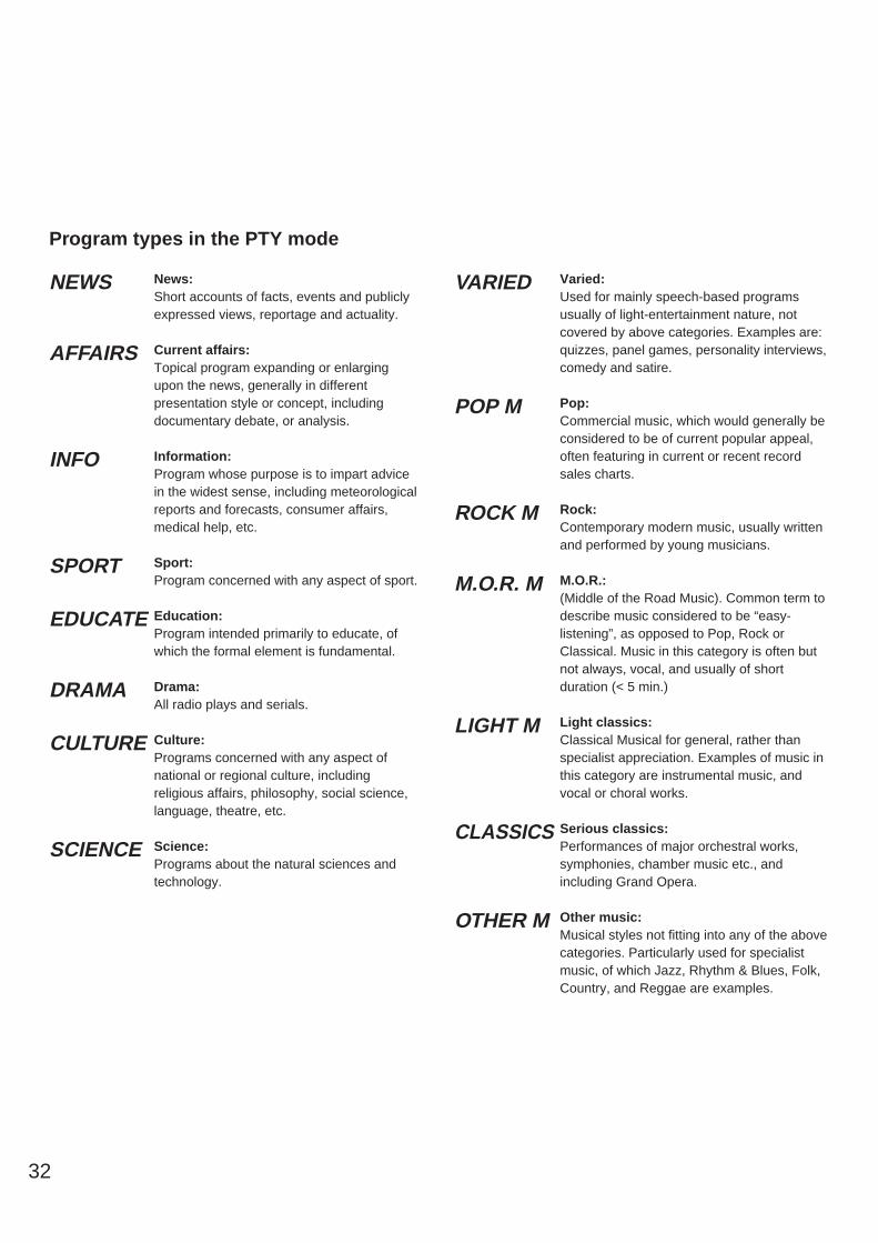
NEWS
AFFAIRS
INFO
SPORT
EDUCATE
DRAMA
CULTURE
SCIENCE
VARIED
POP M
ROCK M
M.O.R. M
LIGHT M
CLASSICS
OTHER M
Program types in the PTY mode
33
En
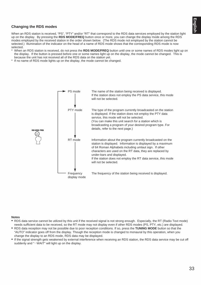
glishChanging the RDS modes
When an RDS station is received, “PS”, “PTY” and/or “RT” that correspond to the RDS data services employed by the station lightup on the display. By pressing the RDS MODE/FREQ button once or more, you can change the display mode among the RDSmodes employed by the received station in the order shown below. (The RDS mode not employed by the station cannot beselected.) Illumination of the indicator on the head of a name of RDS mode shows that the corresponding RDS mode is nowselected.* When an RDS station is received, do not press the RDS MODE/FREQ button until one or some names of RDS modes light up on
the display. If the button is pressed before one or some names light up on the display, the mode cannot be changed. This isbecause the unit has not received all of the RDS data on the station yet.
* If no name of RDS mode lights up on the display, the mode cannot be changed.
PS mode The name of the station being received is displayed.If the station does not employ the PS data service, this modewill not be selected.
PTY mode The type of the program currently broadcasted on the stationis displayed. If the station does not employ the PTY dataservice, this mode will not be selected.(You can make this unit search for a station which isbroadcasting a program of your desired program type. Fordetails, refer to the next page.)
RT mode Information about the program currently broadcasted on thestation is displayed. Information is displayed by a maximumof 64 Roman Alphabets including umlaut sign. If othercharacters are used on the RT data, they are replaced byunder-bars and displayed. If the station does not employ the RT data service, this modewill not be selected.
Frequency The frequency of the station being received is displayed.display mode
RDS MODE/FREQ
Notes• RDS data service cannot be utilized by this unit if the received signal is not strong enough. Especially, the RT (Radio Text mode)
needs sufficient data to be received, so the RT mode may not display even if other RDS modes (PS, PTY, etc.) are displayed.• RDS data reception may not be possible due to poor reception conditions. If so, press the TUNING MODE button so that the
“AUTO” indicator goes off from the display. Though the reception mode is changed to monaural by this operation, when youchange the display to an RDS mode, RDS data may be displayed.
• If the signal strength gets weakened by external interference when receiving an RDS station, the RDS data service may be cut offsuddenly and “...WAIT” will light up on the display.

34
1 Set the unit in the PTY SEEK mode.
* The program type of the station now being received or“NEWS” flashes on the display.
2 Select the desired program type.
3 Begin searching all preset RDS stations.
* The “PTY H” indicator will be illuminated on the display.
• If a station which broadcasts the selected program type isfound, the unit stops at the station and the program typewill be illuminated.
• If the selected station is not the desired one, press thePTY SEEK START button once more.The unit begins searching for another station whichbroadcasts the same program type.
• To stop the search, press the PTY SEEK START buttononce more.
To cancel this functionIf the PTY SEEK MODE button is pressed once more, thePTY SEEK mode is canceled.
By designating a program type, the unit automatically searches all preset stations for an RDS station which broadcasts a program ofthe program type.* There are 15 program types for classifying RDS stations. For details, refer to page 32.
Flashes.
Flashes.
SPEAKERS
OFFON
A/B/C/D/EPRESET STATIONS
TUNING
PTY SELECTOR
KEY MODE
TUNINGMODEFM/AM MEMORY PROGRAM
CENTERMODE
EDIT
AUTO/MAN’L MONO MAN’L/AUTO FM
BASS TREBLE BALANCE0
– +
0
– + L R
INPUTDVD-LD/VCR/V-AUX/TAPE•MD/CD/TUNER/PHONO
VOLUME
0 I0
STANDBY/ON
PHONES
NATURAL SOUND AV RECEIVER RX–V10MK
EON
PTY SEEK
MODE START
6CH/2CH
CINEMA DSP
RDS MODE/FREQ
31
2
PTY SELECTOR
INPUTDVD-LD/VCR/V-AUX/TAPEzMD/CD/TUNER/PHONO6CH / 2CH
PTY SEEK
MODE START
PTY SEEK
MODE START
AUTOPTY H PTY PS RT
m Selecting your desired program type from among preset RDS stations (PTY SEEK)
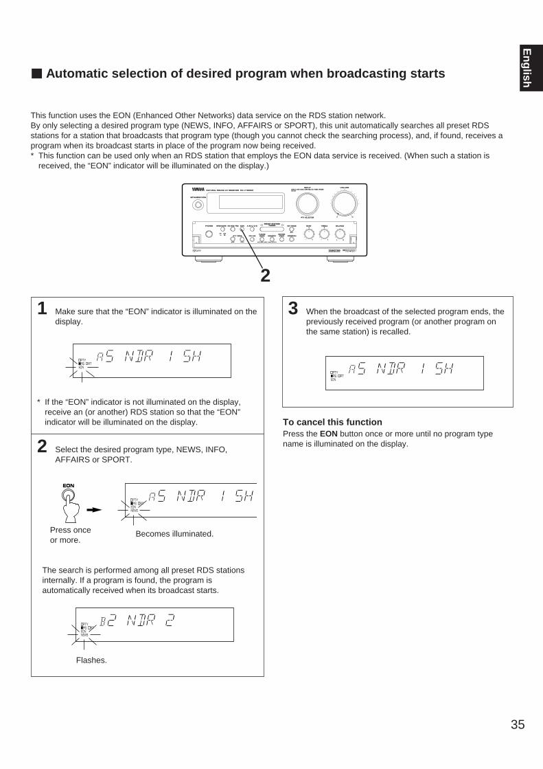
1 Make sure that the “EON” indicator is illuminated on thedisplay.
* If the “EON” indicator is not illuminated on the display,receive an (or another) RDS station so that the “EON”indicator will be illuminated on the display.
2 Select the desired program type, NEWS, INFO,AFFAIRS or SPORT.
Press once or more.
The search is performed among all preset RDS stationsinternally. If a program is found, the program isautomatically received when its broadcast starts.
3 When the broadcast of the selected program ends, thepreviously received program (or another program onthe same station) is recalled.
To cancel this functionPress the EON button once or more until no program typename is illuminated on the display.
35
En
glish
PTY PS RTEONNEWS
Becomes illuminated.
EON
m Automatic selection of desired program when broadcasting starts
This function uses the EON (Enhanced Other Networks) data service on the RDS station network.By only selecting a desired program type (NEWS, INFO, AFFAIRS or SPORT), this unit automatically searches all preset RDSstations for a station that broadcasts that program type (though you cannot check the searching process), and, if found, receives aprogram when its broadcast starts in place of the program now being received.* This function can be used only when an RDS station that employs the EON data service is received. (When such a station is
received, the “EON” indicator will be illuminated on the display.)
SPEAKERS
OFFON
A/B/C/D/EPRESET STATIONS
TUNING
PTY SELECTOR
KEY MODE
TUNINGMODEFM/AM MEMORY PROGRAM
CENTERMODE
EDIT
AUTO/MAN’L MONO MAN’L/AUTO FM
BASS TREBLE BALANCE0
– +
0
– + L R
INPUTDVD-LD/VCR/V-AUX/TAPE•MD/CD/TUNER/PHONO
VOLUME
0 I0
STANDBY/ON
PHONES
NATURAL SOUND AV RECEIVER RX–V10MK
EON
PTY SEEK
MODE START
6CH/2CH
CINEMA DSP
RDS MODE/FREQ
2
PTY PS RTEONNEWS
PTY PS RTEON
PTY PS RTEON
Flashes.
36
m Brief Overview of Digital Sound Field Programs
The following list gives you a brief description of the sound fields produced by each of the DSP programs. Keep in mind that most ofthese are precise digital recreations of actual acoustic environments. The data for these sound fields was recorded at actuallocations using sophisticated sound field measurement equipment.NoteThe channel level balance between the left and right rear effect speakers may vary depending on the sound field you arelistening in. This is due to the fact that most of these sound field recreations are actual acoustic environments.
PROGRAM FEATURE
This program is used for playback of sources encoded with Dolby Surround.PRO LOGIC Dialog is oriented on the screen and effect sounds are effectively located on the left front, right front and
rear surround sides respectively as the movie sound creater designed.
This program is used for playback of sources encoded with Dolby Surround.
PRO LOGICEnhancing the “Normal” Dolby Pro Logic, the DSP technology simulates the multi-surround speaker
ENHANCEDsystems of a 35 mm movie theater. This effect creates a wide surround sound field, and expands thesound stage with an improved presence image. This program is suitable for musical based movies, as wellas drama and action based movies.
CONCERT VIDEOThis program is effective for music videos and gives excellent depth and clarity for vocals. For opera, theorchestra and stage are ideally recreated, letting you feel as if you were in an actual concert hall.
MONO MOVIE
This program is designed specifically to enhance mono source programs. Compared to a strictly monosetting, the sound image created in this mode is wider and slightly forward of the speaker pair, lending animmediacy to the overall sound. It is particularly effective when used with old mono movies, newsbroadcasts and dialog.
ROCK CONCERT This program is ideally suited for rock music. You will experience a very dynamic or lively sound field.
CONCERT HALLIn this program, the center will appear to be deep behind the main speakers, creating an expansive largehall ambience. Orchestra and opera music are suited for this sound field.
USING DIGITAL SOUND FIELD PROCESSOR (DSP)This unit incorporates a sophisticated, multi-program digital sound field processor. The processor allows you to electronically expandand change the shape of the audio sound field from both audio and video sources, creating a theater-like experience in yourlistening room. You can create an excellent audio sound field by selecting a suitable sound field program (this will, of course, dependon what you will be listening to), and adding desired adjustments.
In addition, this unit incorporates a Dolby Pro Logic Surround decoder for multi-channel sound reproduction of sources encoded withDolby Surround. The operation of the Dolby Pro Logic Surround decoder can be controlled by selecting a corresponding DSPprogram including a combined operation of Yamaha DSP and Dolby Pro Logic Surround.
37
En
glish
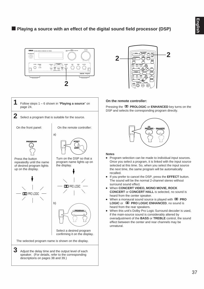
1 Follow steps 1 – 6 shown in “Playing a source” on page 24.
2 Select a program that is suitable for the source.
On the front panel: On the remote controller:
a)
Turn on the DSP so that aprogram name lights up onthe display.
b)
Select a desired programconfirming it on the display.
The selected program name is shown on the display.
3 Adjust the delay time and the output level of eachspeaker. (For details, refer to the correspondingdescriptions on pages 38 and 39.)
On the remote controller:
Pressing the PROLOGIC or ENHANCED key turns on theDSP and selects the corresponding program directly.
Notes Program selection can be made to individual input sources.
Once you select a program, it is linked with the input sourceselected at this time. So, when you select the input sourcethe next time, the same program will be automaticallyrecalled.
If you prefer to cancel the DSP, press the EFFECT button.The sound will be the normal 2-channel stereo withoutsurround sound effect.
When CONCERT VIDEO, MONO MOVIE, ROCKCONCERT or CONCERT HALL is selected, no sound isheard from the center speaker.
When a monaural sound source is played with PROLOGIC or PRO LOGIC ENHANCED, no sound isheard from the rear speakers.
When this unit’s Dolby Pro Logic Surround decoder is used,if the main-source sound is considerably altered byoveradjustment of the BASS or TREBLE control, the soundeffect between the center and rear channels may beunnatural.
m Playing a source with an effect of the digital sound field processor (DSP)
SPEAKERS
OFFON
A/B/C/D/EPRESET STATIONS
TUNING
PTY SELECTOR
KEY MODE
TUNINGMODEFM/AM MEMORY PROGRAM
CENTERMODE
EDIT
AUTO/MAN’L MONO MAN’L/AUTO FM
BASS TREBLE BALANCE0
– +
0
– + L R
INPUTDVD-LD/VCR/V-AUX/TAPE•MD/CD/TUNER/PHONO
VOLUME
0 I0
STANDBY/ON
PHONES
NATURAL SOUND AV RECEIVER RX–V10MK
EON
PTY SEEK
MODE START
6CH/2CH
CINEMA DSP
RDS MODE/FREQ
2
PRO LOGIC
EFFECT
ON/OFF
PROGRAM
REC/PAUSEDIR BDIR A PLAY
DISC
VOLUME
PLAY
DVD/LD2CH/6CH
PRESET A/B/C/D/E– +
LEVELDELAY/CENTER
/REAR/SWFR TEST EFFECT
PROGRAM PROLOGIC ENHANCED
– +
SLEEP
TAPEA/B
ON/OFF
TUNER
CD
PHONO
VCRV-AUX
POWER /I
PROLOGIC ENHANCED
Press the buttonrepeatedly until the nameof desired program lightsup on the display.
PROGRAM
PRO LOGIC
2 2
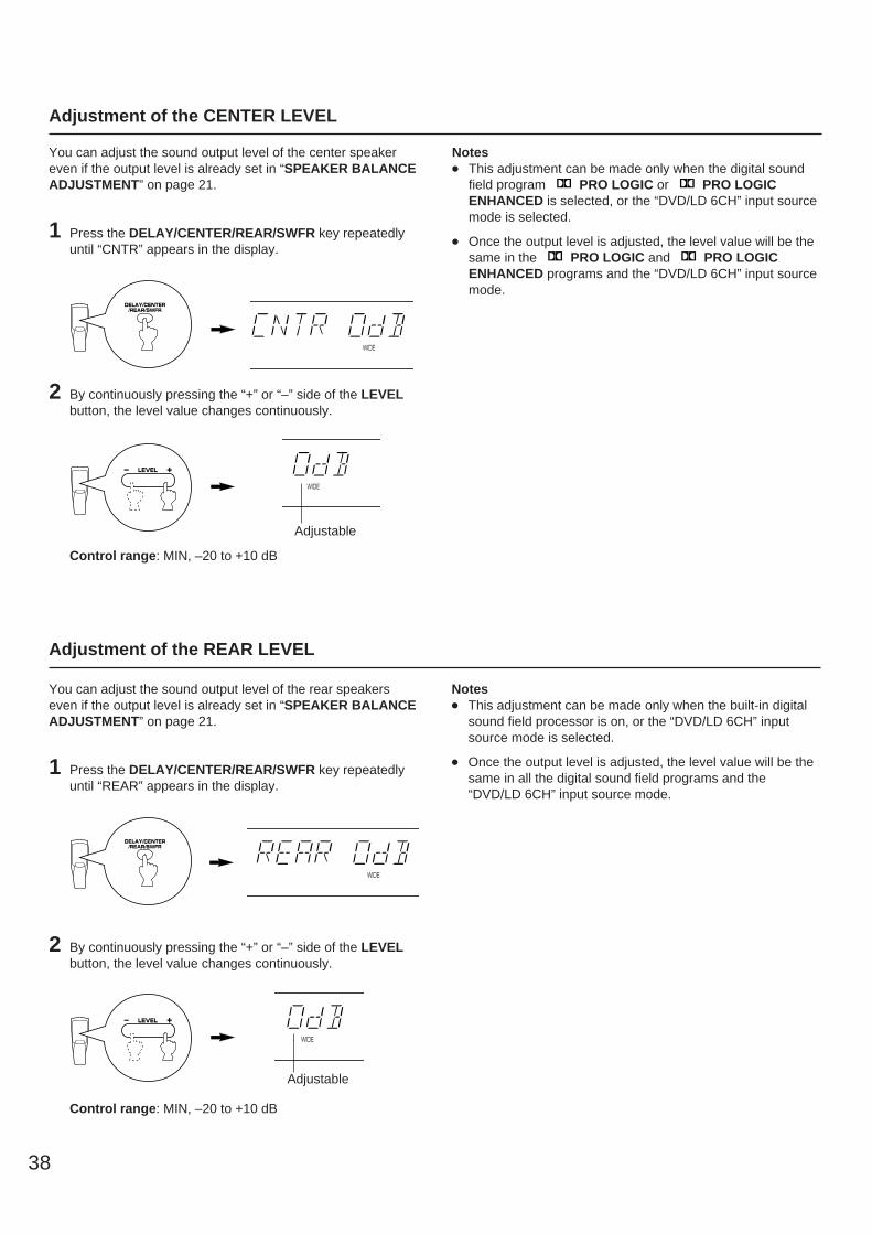
You can adjust the sound output level of the center speakereven if the output level is already set in “SPEAKER BALANCEADJUSTMENT” on page 21.
1 Press the DELAY/CENTER/REAR/SWFR key repeatedlyuntil “CNTR” appears in the display.
2 By continuously pressing the “+” or “–” side of the LEVELbutton, the level value changes continuously.
Control range: MIN, –20 to +10 dB
Notes This adjustment can be made only when the digital sound
field program PRO LOGIC or PRO LOGICENHANCED is selected, or the “DVD/LD 6CH” input sourcemode is selected.
Once the output level is adjusted, the level value will be thesame in the PRO LOGIC and PRO LOGICENHANCED programs and the “DVD/LD 6CH” input sourcemode.
38
Adjustment of the CENTER LEVEL
DELAY/CENTER/REAR/SWFR
Adjustment of the REAR LEVEL
You can adjust the sound output level of the rear speakerseven if the output level is already set in “SPEAKER BALANCEADJUSTMENT” on page 21.
1 Press the DELAY/CENTER/REAR/SWFR key repeatedlyuntil “REAR” appears in the display.
2 By continuously pressing the “+” or “–” side of the LEVELbutton, the level value changes continuously.
Control range: MIN, –20 to +10 dB
Notes This adjustment can be made only when the built-in digital
sound field processor is on, or the “DVD/LD 6CH” inputsource mode is selected.
Once the output level is adjusted, the level value will be thesame in all the digital sound field programs and the“DVD/LD 6CH” input source mode.
WIDE
DELAY/CENTER/REAR/SWFR
TESTWIDE
LEVEL– +
Adjustable
TESTWIDE
LEVEL– +
Adjustable
WIDE
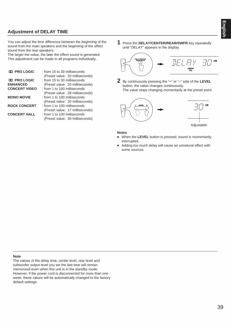
39
En
glishAdjustment of DELAY TIME
You can adjust the time difference between the beginning of thesound from the main speakers and the beginning of the effectsound from the rear speakers.The larger the value, the later the effect sound is generated. This adjustment can be made to all programs individually.
PRO LOGIC : from 15 to 30 milliseconds(Preset value: 20 milliseconds)
PRO LOGIC : from 15 to 30 millisecondsENHANCED (Preset value: 20 milliseconds)CONCERT VIDEO : from 1 to 100 milliseconds
(Preset value: 28 milliseconds)MONO MOVIE : from 1 to 100 milliseconds
(Preset value: 20 milliseconds)ROCK CONCERT : from 1 to 100 milliseconds
(Preset value: 17 milliseconds)CONCERT HALL : from 1 to 100 milliseconds
(Preset value: 30 milliseconds)
1 Press the DELAY/CENTER/REAR/SWFR key repeatedlyuntil “DELAY” appears in the display.
2 By continuously pressing the “+” or “–” side of the LEVELbutton, the value changes continuously.The value stops changing momentarily at the preset point.
Notes When the LEVEL button is pressed, sound is momentarily
interrupted. Adding too much delay will cause an unnatural effect with
some sources.
NoteThe values of the delay time, center level, rear level andsubwoofer output level you set the last time will remainmemorized even when this unit is in the standby mode.However, if the power cord is disconnected for more than oneweek, these values will be automatically changed to the factorydefault settings.
LEVEL– +
DELAY/CENTER/REAR/SWFR
Adjustable
CONCERTHALL
mS
mS
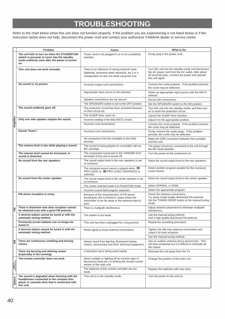
40
Am
plif
ier
FM
AM
Oth
ers
RE
MO
TE
CO
NT
RO
LL
ER
Refer to the chart below when this unit does not function properly. If the problem you are experiencing is not listed below or if theinstruction below does not help, disconnect the power cord and contact your authorized YAMAHA dealer or service center.
Problem
The unit fails to turn on when the STANDBY/ONswitch is pressed, or turns into the standbymode suddenly soon after the power is turnedon.
This unit does not work normally.
No sound or no picture.
The sound suddenly goes off.
Only one side speaker outputs the sound.
Sound “hums”.
The volume level is low while playing a record.
The volume level cannot be increased, orsound is distorted.
No sound from the rear speakers.
No sound from the center speaker.
FM stereo reception is noisy.
There is distortion and clear reception cannotbe obtained even with a good FM antenna.
A desired station cannot be tuned in with theautomatic tuning method.
Previously preset stations can no longer betuned in.
A desired station cannot be tuned in with theautomatic tuning method.
There are continuous crackling and hissingnoises.
There are buzzing and whining noises(especially in the evening).
The remote controller does not work.
The sound is degraded when listening with theheadphones connected to the compact discplayer or cassette deck that is connected withthis unit.
Cause
Power cord is not plugged in or is not completelyinserted.
There is an influence of strong external noise(lightning, excessive static electricity, etc.) or amisoperation on this unit while using this unit.
Incorrect output cord connections.
Appropriate input source is not selected.
Speaker connections are not secure.
The SPEAKERS switch is set to the OFF position.
The protection circuit has been activated because of short circuit etc.
The SLEEP timer came on.
Incorrect setting of the BALANCE control.
Incorrect cord connections.
Incorrect cord connections.
No connection from the turntable to the GNDterminal.
The record is being played on a turntable with anMC cartridge.
The component connected to the TAPE/MD OUTterminals of this unit is turned off.
The sound output level to the rear speakers is setto minimum.
The monaural sound source is played when PRO LOGIC or PRO LOGIC ENHANCED isselected.
The sound output level to the center speaker is setto minimum.
The center channel mode is in PHANTOM mode.
Incorrect sound field program selection.
Because of the characteristics of FM stereobroadcasts, this is limited to cases where thetransmitter is too far away or the antenna input ispoor.
There is multipath interference.
The station is too weak.
This unit has been unplugged for a long period.
Weak signal or loose antenna connections.
Noises result from ligtning, fluorescent lamps,motors, thermostats and other electrical equipment.
A television set is being used nearby.
Direct sunlight or lighting (of an inverter type offluorescent lamp etc.) is striking the remote controlsensor of the main unit.
The batteries of this remote controller are too weak.
This unit is in the standby mode.
What to Do
Firmly plug in the power cord.
Turn this unit into the standby mode and disconnectthe AC power cord from the AC outlet. After about30 seconds pass, connect the power and operatethis unit again.
Connect the cords properly. If the problem persists,the cords may be defective.
Select an appropriate input source with the INPUTselector.
Secure the connections.
Set the SPEAKERS switch to the ON position.
Turn this unit into the standby mode, and then turnon to reset the protection circuit.
Cancel the SLEEP timer function.
Adjust it to the appropriate position.
Connect the cords properly. If the problem persists,the cords may be defective.
Firmly connect the audio plugs. If the problempersists, the cords may be defective.
Make the GND connection between the turntableand this unit.
The player should be connected to the unit throughthe MC head amplifier.
Turn the power to the component on.
Raise the sound output level to the rear speakers.
Select another program suitable for the monauralsound source.
Raise the sound output level to the center speaker.
Select NORMAL or WIDE.
Select the appropriate program.
Check the antenna connections.Try using a high quality directional FM antenna.Set the TUNING MODE button to the manual tuningmode.
Adjust antenna placement to eliminate multipathinterference.
Use the manual tuning method.Use a high quality directional FM antenna.
Repeat the presetting procedure.
Tighten the AM loop antenna connections androtate it for best reception.
Use the manual tuning method.
Use an outdoor antenna and a ground wire. Thiswill help somewhat but it is difficult to eliminate allthe noises.
Relocate this unit away from the TV.
Change the position of the main unit.
Replace the batteries with new ones.
Turn the power to this unit on.
TROUBLESHOOTING
41
En
glish
SPECIFICATIONSAUDIO SECTIONMinimum RMS Output Power per ChannelMAIN L, R
8 ohms, 20 Hz to 20 kHz, 0.04% THD...................................................45W+45W
CENTER8 ohms, 1 kHz, 0.04% THD ....................45W
REAR L,R8 ohms, 1 kHz, 0.3% THD............15W+15W
Dynamic Power per Channel(by IHF Dynamic Headroom measuring
method)8 ohms..........................................65W+65W6 ohms..........................................75W+75W4 ohms..........................................95W+95W2 ohms......................................105W+105W
DIN Standard Output Power per Channel4 ohms, 1 kHz, 0.7% THD
[Europe model only]...................60W+60W
IEC Power per Channel8 ohms, 1 kHz, 0.1% THD
[Europe model only]...................50W+50W
Power Band Width 8 ohms, 22.5W, 0.1% THD
..........................................10 Hz to 50 kHz
Maximum Power per Channel[General model only]MAIN L, R (1 kHz, 10% THD, 8 ohms).....................................................65W+65W
Input Sensitivity/ImpedancePHONO MM.....................2.5 mV/47 k-ohmsCD/TAPEzMD/DVD·LD/VCR/V-AUX........................................150 mV/47 k-ohms6CH DISCRT INPUT
MAIN L, R ......................150 mV/70 k-ohms CENTER .......................150 mV/40 k-ohms SURROUND L, R ...........90 mV/40 k-ohms SUBWOOFER ..............150 mV/40 k-ohms
Maximum Input Signal (1 kHz, 0.5% THD)PHONO MM......................................100 mVCD/TAPEzMD/DVD·LD/VCR/V-AUX (EFFECT ON) ........................................2.5V
Output Level/ImpedanceREC OUT.......................150 mV/0.9 k-ohmsSUBWOOFER ...................3.5V/1.6 k-ohms
Headphone Jack Rated Output/ImpedanceOutput Level (8 ohms, 1 kHz, 150 mV Input).............................................................0.45VImpedance.....................................330 ohms
Frequency Response (20 Hz to 20 kHz)CD/TAPEzMD/DVD·LD/VCR/V-AUX........................................................0±0.5 dB
RIAA Equalization DeviationPHONO MM....................................0±0.5 dB
Total Harmonic DistortionPHONO MM to REC OUT
20 Hz to 20 kHz, 1V..........................0.02%CD/TAPEzMD/DVD·LD/VCR/V-AUX to SP OUT
20 Hz to 20 kHz, 22.5W/8 ohms ......0.02%
Signal-to-Noise Ratio (IHF-A Network)PHONO MM to REC OUT (5 mV Input Shorted) ...........................82 dBCD/TAPEzMD/DVD·LD/VCR/V-AUX to SPOUT (Shorted) ....................................95 dB
Residual Noise (IHF-A Network)MAIN L/R ...........................................140 µV
Channel Separation (Vol. MAX, EFFECT OFF)PHONO MM
(Input Shorted, 1 kHz) .......................60 dBCD/TAPEzMD/DVD·LD/VCR/V-AUX
(Input 5.1 k-ohms Terminated, 1 kHz)..........................................................60 dB
Tone Control CharacteristicsBASS: Boost/cut ................±10 dB (50 Hz)
Turnover Frequency .........(350 Hz)TREBLE: Boost/cut...........±10 dB (20 kHz)
Turnover Frequency.....(3.5 kHz)
Gain Tracking Error (0 to –60 dB) ............3 dB
VIDEO SECTIONVideo Signal Level..................1 Vp-p/75 ohms
Maximum Input Level .........................1.5 Vp-p
Signal-to-Noise Ratio .............................50 dB
Monitor Out Frequency Response..................................5 Hz to 10 MHz, –3 dB
FM SECTIONTuning Range ......................87.5 to 108.0 MHz
50 dB Quieting Sensitivity (IHF, 1 kHz, 100% mod., 75 ohms)
[General model only]Mono ..............................1.6 µV (15.3 dBf)Stereo..............................23 µV (38.5 dBf)
Usable Sensitivity (75 ohms)DIN, Mono (S/N 26 dB)
[Europe and U.K. models] .................0.9 µVDIN, Stereo (S/N 46 dB)
[Europe and U.K. models] ..................28 µV
Alternate Channel Selectivity [General model].....................................75 dB
Selectivity (two signals, 40 kHz Dev., ±300 kHz)[Europe and U.K. models] .....................55 dB
Signal-to-Noise Ratio(IHF) Mono/Stereo
[General model] .......................80 dB/75 dB(DIN-Weighted, 40 kHz Dev.) Mono/Stereo
[Europe and U.K. models] ........74 dB/69 dB
Harmonic DistortionMono/Stereo (1 kHz)
[General model] .............................0.1/0.2%Mono/Stereo (40 kHz Dev.)
[Europe and U.K. models]..............0.1/0.2%
Stereo Separation (1 kHz)[General model]....................................48 dB[Europe and U.K. models (40 kHz Dev.)].............................................................48 dB
Frequency Response30 Hz to 15 kHz ................................0 ±1 dB
AM SECTIONTuning Range
[General model] ..................530 to 1,710 kHz[Europe and U.K. models].............................................531 to 1,611 kHz
Usable Sensitivity .............................300 µV/m
Signal-to-Noise Ratio .............................50 dB
AUDIO SECTIONOutput Level
FM (100% mod., 1 kHz)[General model] ...............................500 mV[Europe and U.K. models (40 kHz Dev.)].........................................................400 mV
AM (30% mod., 1 kHz) .......................150 mV
GENERALPower Supply
[U.K. model] ..........................AC 230V, 50 Hz[Europe model]......................AC 230V, 50 Hz[General model]....................AC 110/120/220/240V, 50/60 Hz
Power Consumption ...............................160W
Maximum Power Consumption[General model only]............................360W
AC Outlets2 SWITCHED OUTLETS
[Europe and General models]..........................................100W max. total
1 SWITCHED OUTLET[U.K. model] ......................100W max. total
Dimensions (W x H x D)........................................280 x 119 x 389 mm
(11” x 4-11/16” x 15-5/16”)
Weight .............................7.3 kg (16 lbs. 1 oz.)
Accessories ..........................AM loop antennaIndoor FM antenna
Remote controllerBatteries
75-ohm/300-ohmantenna adapter
(U.K. model only)
Specifications are subject to change withoutnotice.

V289750
YAMAHA ELECTRONICS CORPORATION, USA 6660 ORANGETHORPE AVE., BUENA PARK, CALIF. 90620, U.S.A.YAMAHA CANADA MUSIC LTD. 135 MILNER AVE., SCARBOROUGH, ONTARIO M1S 3R1, CANADAYAMAHA ELECTRONIK EUROPA G.m.b.H. SIEMENSSTR. 22-34, 25462 RELLINGEN BEI HAMBURG, F.R. OF GERMANYYAMAHA ELECTRONIQUE FRANCE S.A. RUE AMBROISE CROIZAT BP70 CROISSY-BEAUBOURG 77312 MARNE-LA-VALLEE CEDEX02, FRANCEYAMAHA ELECTRONICS (UK) LTD. YAMAHA HOUSE, 200 RICKMANSWORTH ROAD WATFORD, HERTS WD1 7JS, ENGLANDYAMAHA SCANDINAVIA A.B. J A WETTERGRENS GATA 1, BOX 30053, 400 43 VÄSTRA FRÖLUNDA, SWEDENYAMAHA MUSIC AUSTRALIA PTY, LTD. 17-33 MARKET ST., SOUTH MELBOURNE, 3205 VIC., AUSTRALIA
Printed in Malaysia


![Xtreme Tuner Plus for GeForce 20 & 16 Series ユー …1「Xtreme Tunerをダウンロードする」(P. 3)でダウンロードしたファイルを展開します。2 展開されたファイル(XtremeTuner_Android.EXE)を実行します。3[Next]をクリックします。](https://static.fdocuments.nl/doc/165x107/5f84f181b0019e6be51c5177/xtreme-tuner-plus-for-geforce-20-16-series-ff-1oextreme-tunerfffffip.jpg)