Alpha Con 100 Dutch
29
0 INHOUDSOPGAVE 1. INTRODUCTIE 1 2. BEDIENING 3 2.1 Voor Panel 3 2.2 Achter Panel 5 2.3 Selecteren geleidbaarheids Meet Bereik 4 2.4 Bedrading 6 3. BEDIENEN VAN DE CONTROLLER 7 Het hoofd display 7 4. HET INSTELLEN VAN DE CONTROLLER 8 4.1 Instellen en veranderen van het password 8 4.2 Instellen van het controller bereik (Software) 9 5. HET IJKEN VAN DE CONTROLLER 11 5.1 De lage Level Menu's 11 5.2 IJking voor de geleidbaarheidsmeting 11 5.3 IJking voor de temperatuur meting 12 5.4 Instellen van Alarm 15 5.5 Instellen van Temperatuur Coëfficient 19 6. TERUG ZETTEN NAAR FABRIEKS INSTELLING20 7. GEBRUIK VAN DE CONTROLLER CURRENT LOOP VOOR GEGEVENS OPSLAG (ALLEEN MOGELIJK MET TRANSMITTER MODEL) 21 8. TOEVOEGENDE INFORMATIE 22 Paragraaf 1 23 Paragraaf 2 24 Paragraaf 3 25 Technische Specificaties 26
-
Upload
de-heksenketel -
Category
Documents
-
view
222 -
download
0
Transcript of Alpha Con 100 Dutch
8/14/2019 Alpha Con 100 Dutch
http://slidepdf.com/reader/full/alpha-con-100-dutch 1/29
0
INHOUDSOPGAVE
1. INTRODUCTIE 1
2. BEDIENING 3
2.1 Voor Panel 3
2.2 Achter Panel 5
2.3 Selecteren geleidbaarheids Meet Bereik 4
2.4 Bedrading 6
3. BEDIENEN VAN DE CONTROLLER 7
Het hoofd display 74. HET INSTELLEN VAN DE CONTROLLER 8
4.1 Instellen en veranderen van het password 8
4.2 Instellen van het controller bereik (Software) 9
5. HET IJKEN VAN DE CONTROLLER 11
5.1 De lage Level Menu's 11
5.2 IJking voor de geleidbaarheidsmeting 11
5.3 IJking voor de temperatuur
meting 12
5.4 Instellen van Alarm 15
5.5 Instellen van Temperatuur Coëfficient 19
6. TERUG ZETTEN NAAR FABRIEKS INSTELLING20
7. GEBRUIK VAN DE CONTROLLER CURRENTLOOP VOOR GEGEVENS OPSLAG (ALLEENMOGELIJK MET TRANSMITTER MODEL) 21
8. TOEVOEGENDE INFORMATIE 22
Paragraaf 1 23
Paragraaf 2 24
Paragraaf 3 25
Technische Specificaties 26
8/14/2019 Alpha Con 100 Dutch
http://slidepdf.com/reader/full/alpha-con-100-dutch 2/29
1
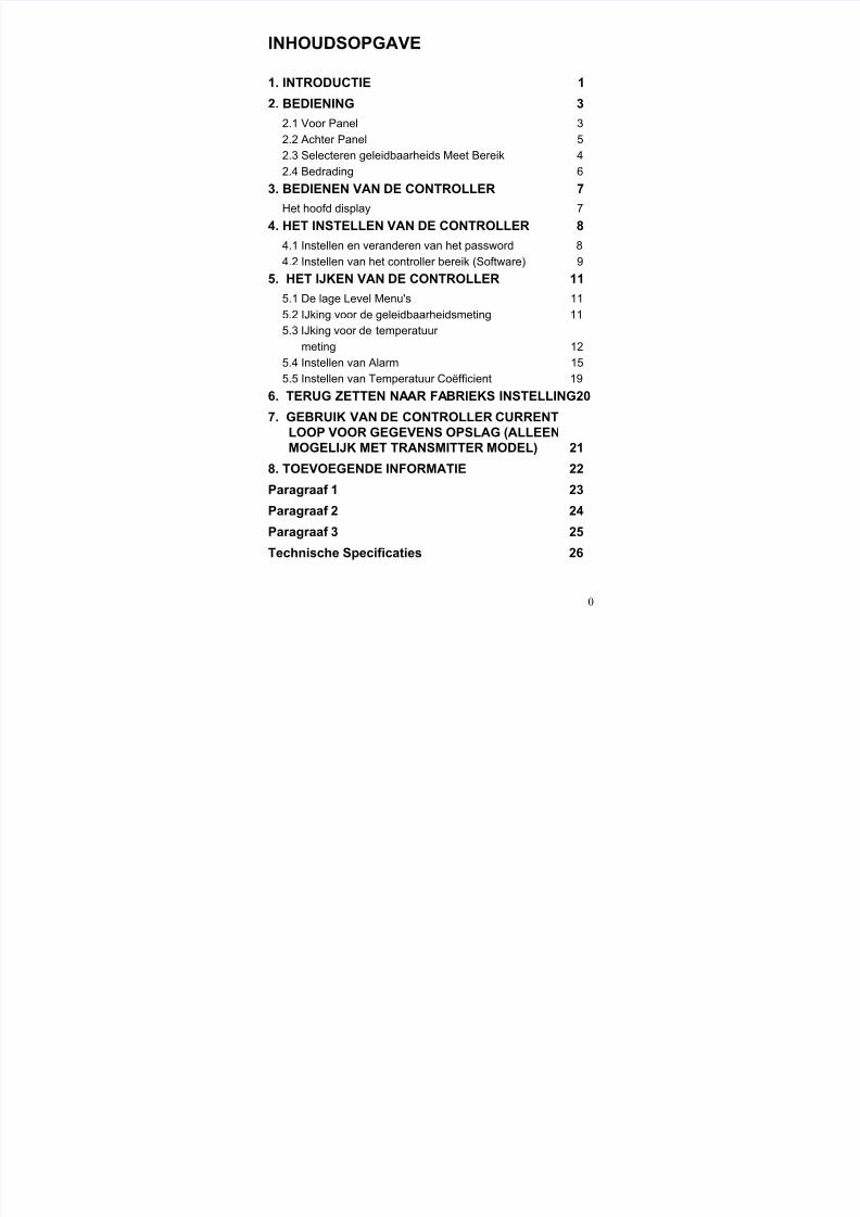
1. INTRODUCTIE
De Alpha CON 100 series Conductivity Controller/Transmitter iseen toevoeging aan de lijn van process controllers van EutechInstruments. Met een ingebouwde ASIC (Application SpecificIntegrated Circuit) microprocessor technology, de on-linecontroller is voorzien van veel gebruiks vriendelijkemogenlijkheden die wenselijk zijn bij geleidbaarheidsControllers.
Deze veelzijdige controller kan gebruikt worden voor het metenen controleren van de geleidbaarheid van een groot aantaloplossingen in de proces industrie.
Geleidbaarheidsbereiken :
Bereik Resolutie Cell Constante0 - 99.9 uS0 - 999 uS0 - 999 uS0 - 9.99 mS0 - 99.9 mS0 - 200 mS0 - 200 mS
0.1 uS1 uS1 uS
0.01 mS0.1 mS1 mS1 mS
0.10.11.01.01.01.0
10.0

8/14/2019 Alpha Con 100 Dutch
http://slidepdf.com/reader/full/alpha-con-100-dutch 3/29
2
Een aantal mogelijkheden van deze controler zijn :
• Automatische temperatuut compensatie (met pt 100)• Handmatig de temperatuur compensatie instellen
zonder een temperatuur electrode hierbij te gebruiken• Aanpasbare temperatuur coëficient 0.0 tot 10.0%• Drukknop ijking met een cel correctie functie• Hoog en Laag alarm triggering relays• Door de gebruiker in te stellen Password om er voor te
waken dat iemand anders u calibratie punten, hysteresisfunctie, hoog en laag setpunts informatie
• Geeft alarm en functie meldingen weer • Hysteresis functie om te voorkomen dat de relays gaan
switchen rond het setpoint.• High-end transmitter modellen met 4-20 mA output voor
het opslaan van data mogenlijkheden (schrijver/computer)• Ingebouwde geheugen backup om te verzekeren dat ijking
en andere informatie verloren gaat wanneer de stroomtoevoer uitvalt.
• Over te schakelen hoofd voltages van 110 VAC of 220VAC via een gebruiker te selecteren instelling
8/14/2019 Alpha Con 100 Dutch
http://slidepdf.com/reader/full/alpha-con-100-dutch 4/29
3
2. kennis maken met de controller
2.1 Front Paneel
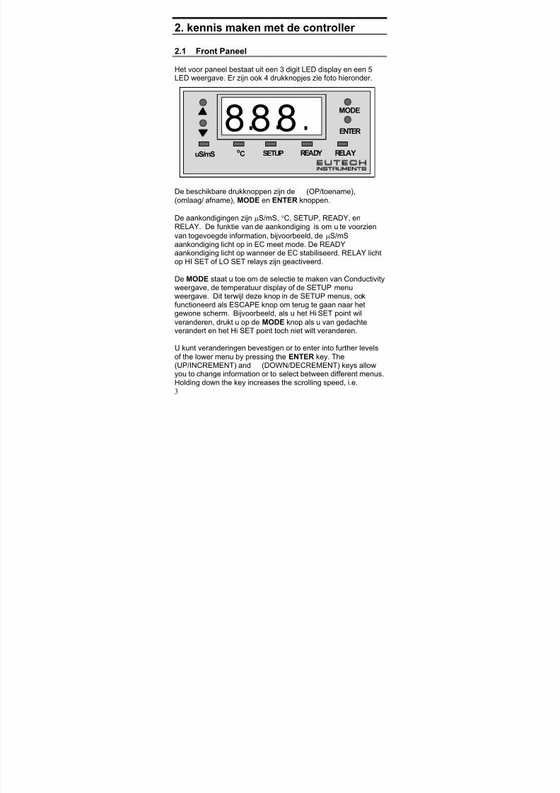
Het voor paneel bestaat uit een 3 digit LED display en een 5LED weergave. Er zijn ook 4 drukknopjes zie foto hieronder.
De beschikbare drukknoppen zijn de L (OP/toename), M (omlaag/ afname), MODE en ENTER knoppen.
De aankondigingen zijn µS/mS, °C, SETUP, READY, enRELAY. De funktie van de aankondiging is om u te voorzien
van togevoegde information, bijvoorbeeld, de µS/mSaankondiging licht op in EC meet mode. De READYaankondiging licht op wanneer de EC stabiliseerd. RELAY lichtop HI SET of LO SET relays zijn geactiveerd.
De MODE staat u toe om de selectie te maken van Conductivityweergave, de temperatuur display of de SETUP menuweergave. Dit terwijl deze knop in de SETUP menus, ookfunctioneerd als ESCAPE knop om terug te gaan naar hetgewone scherm. Bijvoorbeeld, als u het Hi SET point wil
veranderen, drukt u op de MODE knop als u van gedachteverandert en het Hi SET point toch niet wilt veranderen.
U kunt veranderingen bevestigen or to enter into further levelsof the lower menu by pressing the ENTER key. The L (UP/INCREMENT) and M (DOWN/DECREMENT) keys allowyou to change information or to select between different menus.Holding down the key increases the scrolling speed, i.e.
uS/mS
MODE
oC SETUP READY RELAY
ENTER888

8/14/2019 Alpha Con 100 Dutch
http://slidepdf.com/reader/full/alpha-con-100-dutch 5/29
4
changeover of 1st digit (ones) to 2nd (tens) and then 3rd digit(hundreds).
8/14/2019 Alpha Con 100 Dutch
http://slidepdf.com/reader/full/alpha-con-100-dutch 6/29
5
2.2 The Back Panel
The back panel consists of two connectors. The first one is a 4-way screw terminal and the second is a 12-way screw terminal.Refer to the label on top of the unit for diagram.The connection for the 4-way screw terminals are (from the leftto right):1. PT 100 connection2. PT 100 connection3. Conductivity input (Inner core)4. Conductivity input (Outer shield)
The connections for the 12-way screw terminals are (from left toright),
5. Low Set Relay deactivated position6. Low Set Relay center pole7. Low Set Relay activated position8. High Set Relay deactivated position9. High Set Relay center pole10. High Set Relay activated position11. 4-20 mA - ve connection (for transmitter models only)12. 4-20 mA + ve connection (for transmitter models only)13. Protective earth14. Protective earth15. Neutral16. Live

8/14/2019 Alpha Con 100 Dutch
http://slidepdf.com/reader/full/alpha-con-100-dutch 7/29
6
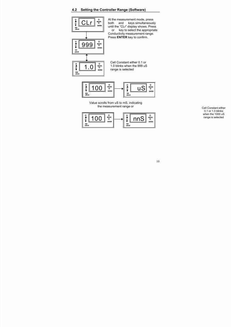
2.3 Selecting Conductivity Measurement Range
You can set the appropriate conductivity measurement rangefrom the front panel. See Section 4.2 for details on Setting theController Range (Software). Note that for “mA” the LEDdisplay shows “nnA”.
2.4 Wiring
Connect the power supply to the GND (EARTH) - 13 or 14,
NEUTRAL - 15 and LIVE - 16 screw terminals. Make sure thatthe power supply jumper setting matches the mains voltage(110 VAC or 220 VAC). See Appendix 2 for the jumper settingfor the voltage selection.
Connect the Conductivity electrode to the 4-way screw terminalat the back panel and the PT 100 temperature probe to the PT100 connections.
Power on the controller and the display automatically shows theConductivity reading. The uS/mS annunciator lights up. Oncethe reading is stable, the READY annunciator lights up.However, if the PT 100 temperature probe is not connected,automatic temperature compensation does not function. Youcan set the temperature at a selected value. The temperature isset to factory default at 25.0
oC.
NOTE : Eutech Instruments will not be responsible for incorrectapplication of the controller using improper voltagesources or wrong jumper settings.
8/14/2019 Alpha Con 100 Dutch
http://slidepdf.com/reader/full/alpha-con-100-dutch 8/29
7
3. Operating the Controller
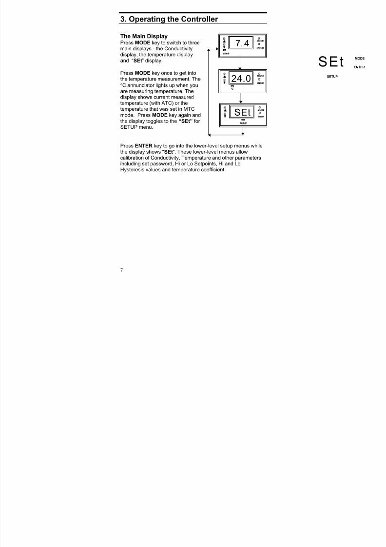
The Main DisplayPress MODE key to switch to threemain displays - the Conductivitydisplay, the temperature displayand “SEt” display.
Press MODE key once to get intothe temperature measurement. The
°C annunciator lights up when youare measuring temperature. The
display shows current measuredtemperature (with ATC) or thetemperature that was set in MTCmode. Press MODE key again andthe display toggles to the “SEt” for SETUP menu.
Press ENTER key to go into the lower-level setup menus whilethe display shows "SEt". These lower-level menus allowcalibration of Conductivity, Temperature and other parametersincluding set password, Hi or Lo Setpoints, Hi and LoHysteresis values and temperature coefficient.
uS/mS
MODE
ENTER
7.4
oC
MODE
ENTER
24.0
SETUP
MODE
ENTER
SEt
SETUP
MODE
ENTERSEt
8/14/2019 Alpha Con 100 Dutch
http://slidepdf.com/reader/full/alpha-con-100-dutch 9/29
8
4. Setting Up the Controller 4.1 Setting and Changing the Password
4.1.1 Setting New Password
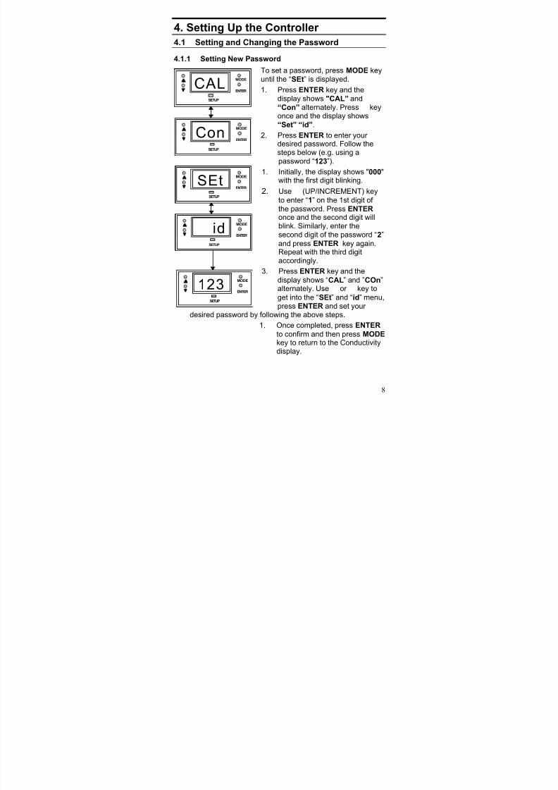
To set a password, press MODE keyuntil the “SEt” is displayed.
1. Press ENTER key and thedisplay shows "CAL” and “Con” alternately. Press L keyonce and the display shows
“Set” “id”.
2. PressENTER
to enter your desired password. Follow thesteps below (e.g. using apassword “123”).
1. Initially, the display shows "000"with the first digit blinking.
2. Use L (UP/INCREMENT) key
to enter “1” on the 1st digit of the password. Press ENTER once and the second digit willblink. Similarly, enter thesecond digit of the password “2”
and press ENTER key again.Repeat with the third digitaccordingly.
3. Press ENTER key and the
display shows “CAL” and ”COn”alternately. Use L or M key to
get into the “SEt” and “id” menu,press ENTER and set your
desired password by following the above steps.
1. Once completed, press ENTER
to confirm and then press MODE key to return to the Conductivitydisplay.
SETUP
MODE
ENTER
CAL
SETUP
MODE
ENTER
Con
SETUP
MODE
ENTER
SEt
SETUP
MODE
ENTER
id
SETUP
MODE
ENTER
123
8/14/2019 Alpha Con 100 Dutch
http://slidepdf.com/reader/full/alpha-con-100-dutch 10/29
9
To calibrate the controller at any time, you may have to enter the password that you set, in order to access the calibrationmode. Once you have entered the password correctly, thedisplay shows "CAL COn” indicating that you are in one of thelower-level SETUP menus.
If you enter the wrong password, the display reverts back to theConductivity display. Alternatively, if you prefer no passwordprotection, set the password to “000”, "CAL COn" immediately
displays after you press ENTER key while you are in the "SEt"menu.
NOTE : The user set password is a protection code. Thus, it is
very important to keep this password strictly confidential toauthorized personnel. You are advised to remember thepassword that you have set, in order to protect the controller settings and prevent any unauthorized tampering to the system!
IMPORTANT : In case the password set is forgotten, usethe master password “555”.
4.1.2 Changing the Password Enter the Set id menu with already set password or “555”.Change a new password as per steps mentioned for setting thepassword.
8/14/2019 Alpha Con 100 Dutch
http://slidepdf.com/reader/full/alpha-con-100-dutch 11/29
8/14/2019 Alpha Con 100 Dutch
http://slidepdf.com/reader/full/alpha-con-100-dutch 12/29
11
5. Calibrating the Controller
5.1 The Lower Level Menus
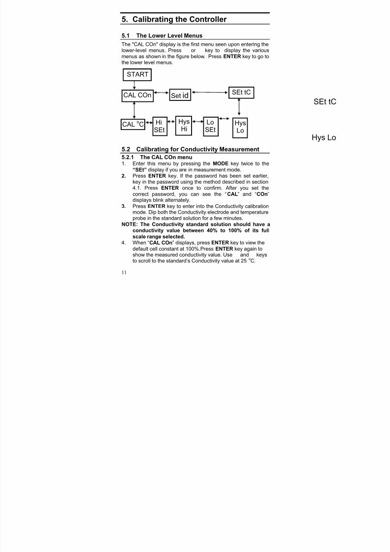
The "CAL COn" display is the first menu seen upon entering thelower-level menus. Press L or M key to display the variousmenus as shown in the figure below. Press ENTER key to go tothe lower level menus.
5.2 Calibrating for Conductivity Measurement5.2.1 The CAL COn menu1. Enter this menu by pressing the MODE key twice to the
“SEt” display if you are in measurement mode.
2. Press ENTER key. If the password has been set earlier,key in the password using the method described in section4.1. Press ENTER once to confirm. After you set the
correct password, you can see the “CAL” and “COn”displays blink alternately.
3. Press ENTER key to enter into the Conductivity calibrationmode. Dip both the Conductivity electrode and temperatureprobe in the standard solution for a few minutes.
NOTE: The Conductivity standard solution should have aconductivity value between 40% to 100% of its fullscale range selected.
4. When “CAL COn” displays, press ENTER key to view the
default cell constant at 100%.Press ENTER key again toshow the measured conductivity value. Use L and M keysto scroll to the standard’s Conductivity value at 25
oC.
Hys Lo
SEt tC
START
CAL COn
CALoC Hi
SEt
HysHi
LoSEt
HysLo
SEt tC
Set id
8/14/2019 Alpha Con 100 Dutch
http://slidepdf.com/reader/full/alpha-con-100-dutch 13/29
12
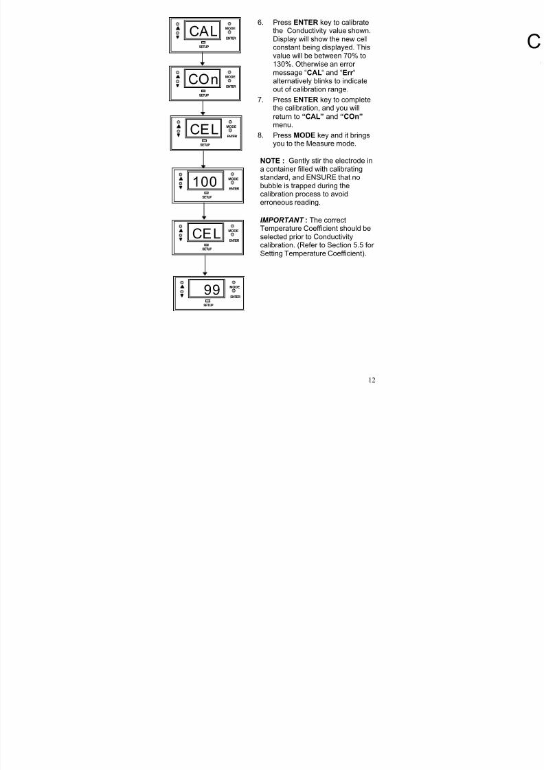
6. Press ENTER key to calibratethe Conductivity value shown.Display will show the new cellconstant being displayed. Thisvalue will be between 70% to130%. Otherwise an error message “CAL“ and “Err “alternatively blinks to indicateout of calibration range.
7. Press ENTER key to completethe calibration, and you will
return to “CAL” and “COn” menu.
8. Press MODE key and it bringsyou to the Measure mode.
NOTE : Gently stir the electrode ina container filled with calibratingstandard, and ENSURE that nobubble is trapped during thecalibration process to avoiderroneous reading.
IMPORTANT : The correctTemperature Coefficient should beselected prior to Conductivitycalibration. (Refer to Section 5.5 for Setting Temperature Coefficient).
SETUP
MODE
ENTER
CAL
SETUP
MODE
ENTER
COn
SETUP
MODE
ENTER
100
SETUP
MODE
ENTER
CEL
SETUP
MODE
ENTER
CEL
SETUP
MODE
ENTER
99
C
8/14/2019 Alpha Con 100 Dutch
http://slidepdf.com/reader/full/alpha-con-100-dutch 14/29
13
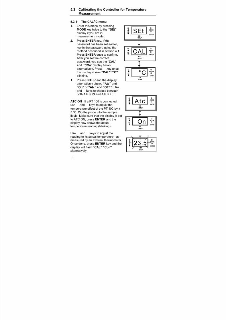
5.3 Calibrating the Controller for TemperatureMeasurement
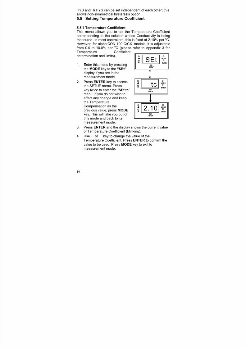
5.3.1 The CAL °C menu1. Enter this menu by pressing
MODE key twice to the “SEt” display if you are inmeasurement mode.
2. Press ENTER key. If thepassword has been set earlier,key in the password using themethod described in section 4.1.
PressENTER
once to confirm.After you set the correct
password, you see the “CAL”and “COn” display blinksalternatively. Press M key once,the display shows “CAL” “oC”blinking.
1. Press ENTER and the display
alternatively shows “Atc” and
“On” or “Atc” and “OFF”. Use L and M keys to choose betweenboth ATC ON and ATC OFF.
ATC ON : If a PT 100 is connected,use L and M keys to adjust the
temperature offset of the PT 100 by ±
5 °C. Dip the probe into the sampleliquid. Make sure that the display is set
to ATC ON, press ENTER and thedisplay now shows the actualtemperature reading (blinking).
Use L and M keys to adjust thereading to its actual temperature - asmeasured by an external thermometer.Once done, press ENTER key and the
display will flash “CAL” “Con”alternatively.
SETUP
MODE
ENTER
SEt
SETUP
MODE
ENTER
CAL
SETUP
MODE
ENTER
oC
SETUP
MODE
ENTER
Atc
SETUP
MODE
ENTER
On
SETUP
MODE
ENTER
23.5

8/14/2019 Alpha Con 100 Dutch
http://slidepdf.com/reader/full/alpha-con-100-dutch 15/29
14
ATC OFF : If a PT 100 is not used,then the ATC should be set to OFF.In step 3 above, choose bypressing L and M keys to selectATC OFF. Then press ENTER.The display will now show thedefault of 25
oC or the last set value
(blinking). Use L and M keys to set
your desired value. Press ENTER to confirm and the display shows
“CAL” “Con”.
Note : For ATC OFF, you canadjust the set temperature valuesfrom 0.0 to 99.9
oC. This value will
be used for its temperaturecompensation e.g. Conductivity in
the MTC mode.
SETUP
MODE
ENTER
Atc
SETUP
MODE
ENTER
OFF
SETUP
MODE
ENTER
25.0
8/14/2019 Alpha Con 100 Dutch
http://slidepdf.com/reader/full/alpha-con-100-dutch 16/29
15
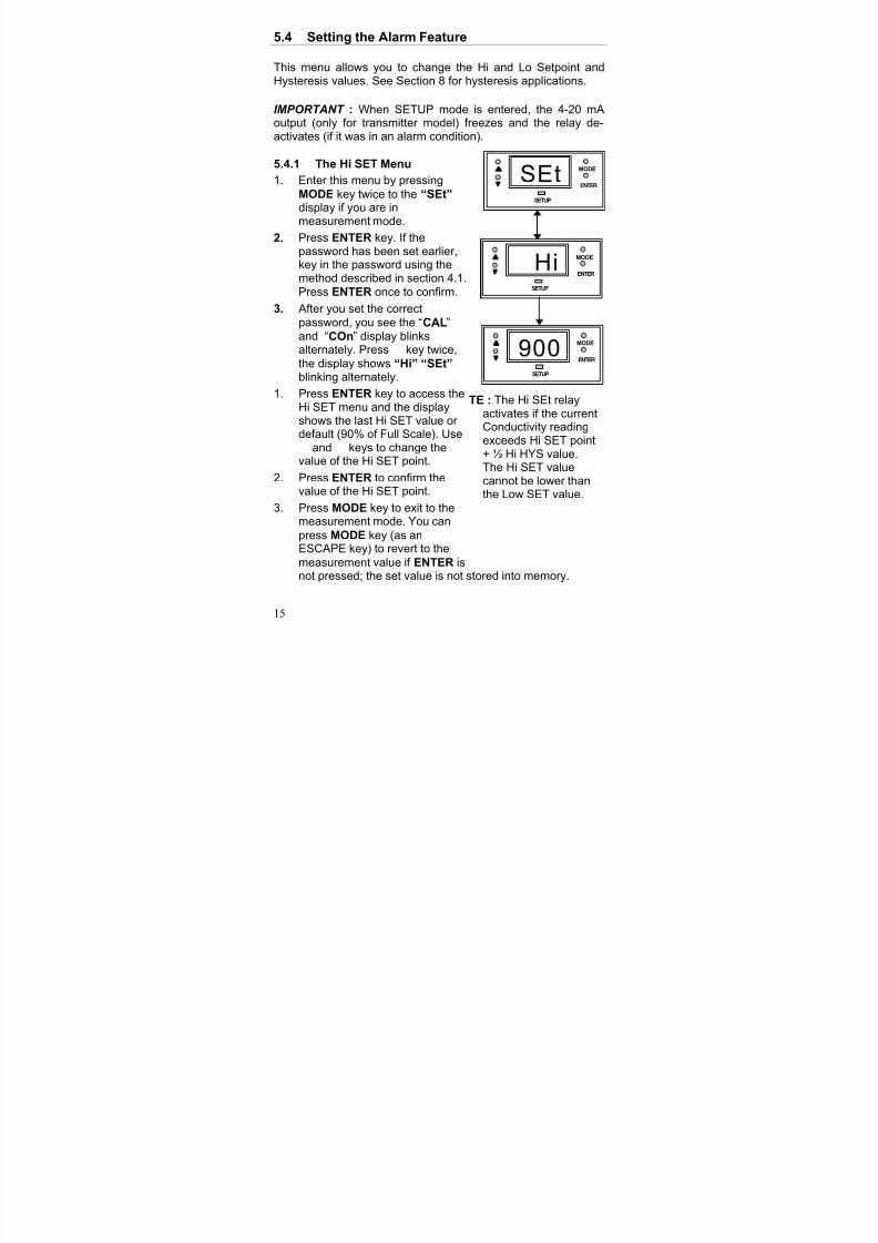
5.4 Setting the Alarm Feature
This menu allows you to change the Hi and Lo Setpoint andHysteresis values. See Section 8 for hysteresis applications.
IMPORTANT : When SETUP mode is entered, the 4-20 mAoutput (only for transmitter model) freezes and the relay de-activates (if it was in an alarm condition).
5.4.1 The Hi SET Menu1. Enter this menu by pressing
MODE key twice to the “SEt” display if you are in
measurement mode.
2. Press ENTER key. If thepassword has been set earlier,key in the password using themethod described in section 4.1.Press ENTER once to confirm.
3. After you set the correctpassword, you see the “CAL”and “COn” display blinksalternately. Press M key twice,the display shows “Hi” “SEt”blinking alternately.
1. Press ENTER key to access theHi SET menu and the displayshows the last Hi SET value or
default (90% of Full Scale). UseL and M keys to change thevalue of the Hi SET point.
2. Press ENTER to confirm thevalue of the Hi SET point.
3. Press MODE key to exit to themeasurement mode. You can
press MODE key (as anESCAPE key) to revert to the
measurement value if ENTER isnot pressed; the set value is not stored into memory.
SETUP
MODE
ENTER
Hi
SETUP
MODE
ENTER
900
SETUP
MODE
ENTER
SEt
TE : The Hi SEt relayactivates if the currentConductivity readingexceeds Hi SET point+ ½ Hi HYS value.The Hi SET valuecannot be lower thanthe Low SET value.
8/14/2019 Alpha Con 100 Dutch
http://slidepdf.com/reader/full/alpha-con-100-dutch 17/29
16
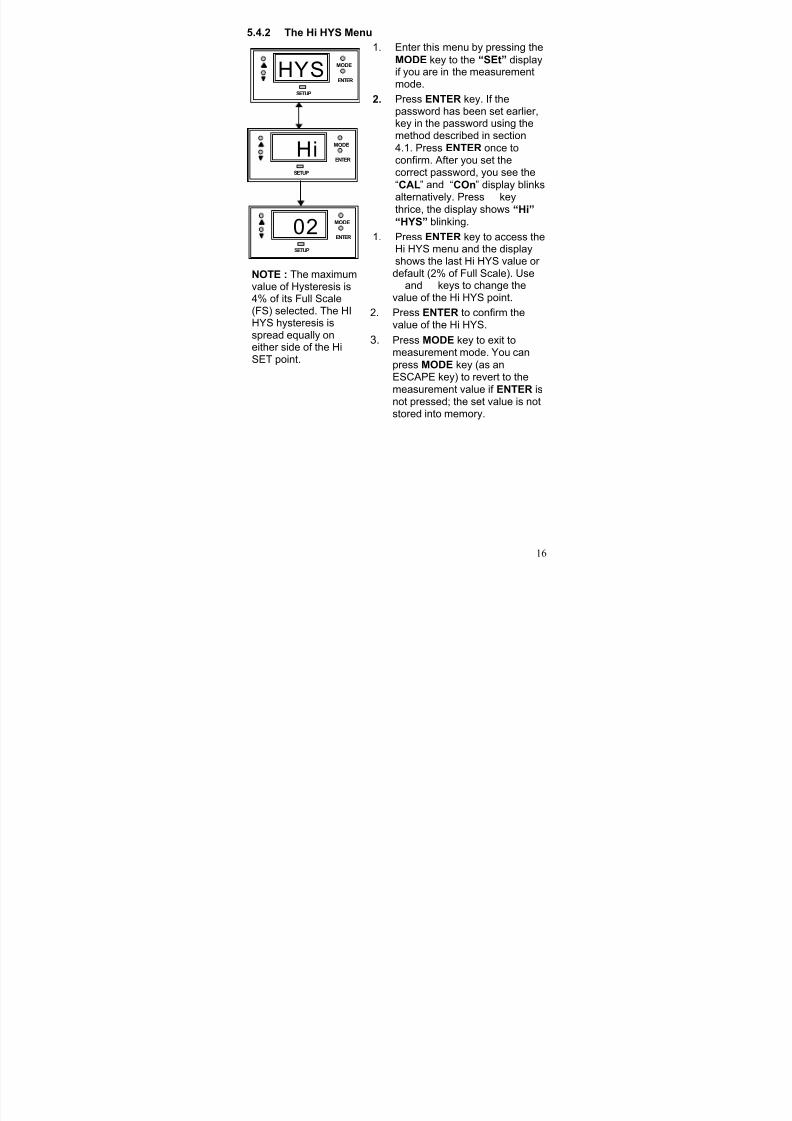
5.4.2 The Hi HYS Menu1. Enter this menu by pressing the
MODE key to the “SEt” displayif you are in the measurementmode.
2. Press ENTER key. If thepassword has been set earlier,key in the password using themethod described in section4.1. Press ENTER once toconfirm. After you set thecorrect password, you see the“CAL” and “COn” display blinks
alternatively. Press M keythrice, the display shows “Hi”
“HYS” blinking.
1. Press ENTER key to access theHi HYS menu and the displayshows the last Hi HYS value or default (2% of Full Scale). UseL and M keys to change thevalue of the Hi HYS point.
2. Press ENTER to confirm thevalue of the Hi HYS.
3. Press MODE key to exit tomeasurement mode. You canpress MODE key (as anESCAPE key) to revert to the
measurement value if ENTER isnot pressed; the set value is notstored into memory.
SETUP
MODE
ENTER
Hi
SETUP
MODE
ENTER
02
SETUP
MODE
ENTER
HYS
NOTE : The maximumvalue of Hysteresis is4% of its Full Scale(FS) selected. The HIHYS hysteresis isspread equally oneither side of the HiSET point.
8/14/2019 Alpha Con 100 Dutch
http://slidepdf.com/reader/full/alpha-con-100-dutch 18/29
17
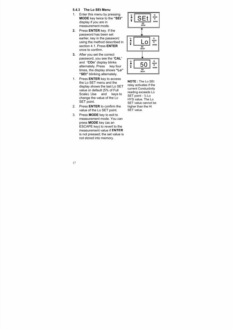
5.4.3 The Lo SEt Menu
1. Enter this menu by pressingMODE key twice to the “SEt” display if you are inmeasurement mode.
2. Press ENTER key. If thepassword has been setearlier, key in the passwordusing the method described in
section 4.1. Press ENTER once to confirm.
3. After you set the correct
password, you see the “CAL”and “COn” display blinksalternately. Press M key four times, the display shows “Lo”
“SEt” blinking alternately.
1. Press ENTER key to accessthe Lo SET menu and thedisplay shows the last Lo SETvalue or default (5% of FullScale). Use L and M keys tochange the value of the LoSET point.
2. Press ENTER to confirm thevalue of the Lo SET point.
3. Press MODE key to exit tomeasurement mode. You canpress MODE key (as anESCAPE key) to revert to themeasurement value if ENTER
is not pressed; the set value isnot stored into memory.
SETUP
MODE
ENTER
Lo
SETUP
MODE
ENTER
50
SETUP
MODE
ENTER
SEt
NOTE : The Lo SEtrelay activates if thecurrent Conductivityreading exceeds LoSET point - ½ LoHYS value. The LoSET value cannot behigher than the HiSET value.
8/14/2019 Alpha Con 100 Dutch
http://slidepdf.com/reader/full/alpha-con-100-dutch 19/29
18
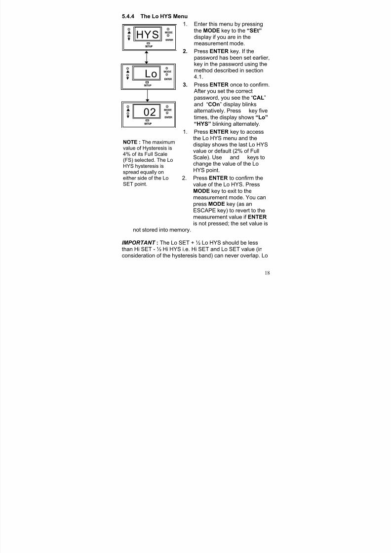
5.4.4 The Lo HYS Menu
1. Enter this menu by pressingthe MODE key to the “SEt” display if you are in themeasurement mode.
2. Press ENTER key. If thepassword has been set earlier,key in the password using themethod described in section4.1.
3. Press ENTER once to confirm.After you set the correct
password, you see the “CAL”and “COn” display blinksalternatively. Press M key five
times, the display shows “Lo” “HYS” blinking alternately.
1. Press ENTER key to accessthe Lo HYS menu and thedisplay shows the last Lo HYSvalue or default (2% of FullScale). Use L and M keys tochange the value of the LoHYS point.
2. Press ENTER to confirm thevalue of the Lo HYS. PressMODE
key to exit to themeasurement mode. You canpress MODE key (as anESCAPE key) to revert to themeasurement value if ENTER
is not pressed; the set value isnot stored into memory.
IMPORTANT : The Lo SET + ½ Lo HYS should be lessthan Hi SET - ½ Hi HYS i.e. Hi SET and Lo SET value (inconsideration of the hysteresis band) can never overlap. Lo
SETUP
MODE
ENTER
Lo
SETUP
MODE
ENTER
02
SETUP
MODE
ENTER
HYS
NOTE : The maximumvalue of Hysteresis is4% of its Full Scale(FS) selected. The LoHYS hysteresis isspread equally oneither side of the LoSET point.
8/14/2019 Alpha Con 100 Dutch
http://slidepdf.com/reader/full/alpha-con-100-dutch 20/29
8/14/2019 Alpha Con 100 Dutch
http://slidepdf.com/reader/full/alpha-con-100-dutch 21/29
8/14/2019 Alpha Con 100 Dutch
http://slidepdf.com/reader/full/alpha-con-100-dutch 22/29
21
7. Using the Controller Current Loopfor Datalogging (for Transmitter Model Only)
The 4-20 mA Current Loop
A 4-20 mA current loop can be connected if a remote datalogging is required. The current will be proportional to theConductivity displayed on the panel display. The 4-20 mA
current loop can drive a load resistance of no more than 200Ω.
If the calculated Conductivity is less than 0 uS (due to incorrectTC and temperature setting), the current will be set toapproximately 0 mA. If Conductivity exceeds the value that canbe measured in the range, current will be set to approximately21 mA. In this way, the remote data logger can detect when outof range conditions arise. Please note that the 4-20 mA loop isnot galvanically isolated from the source.
8/14/2019 Alpha Con 100 Dutch
http://slidepdf.com/reader/full/alpha-con-100-dutch 23/29
22
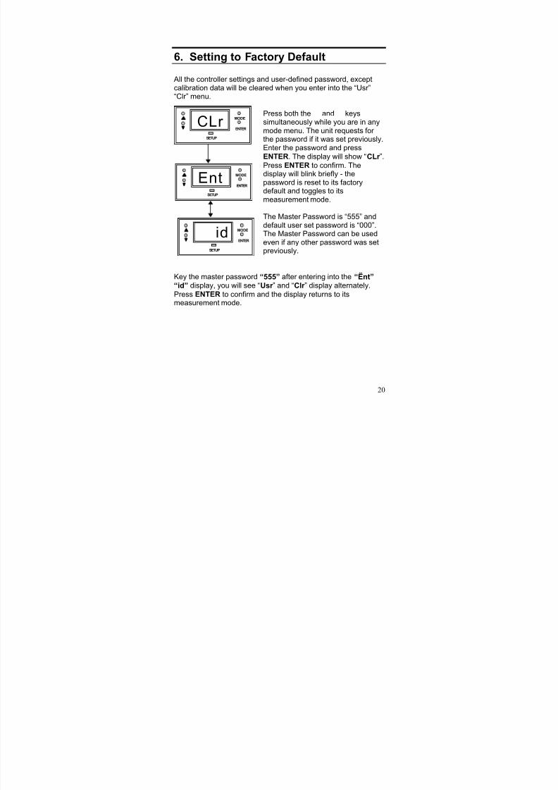
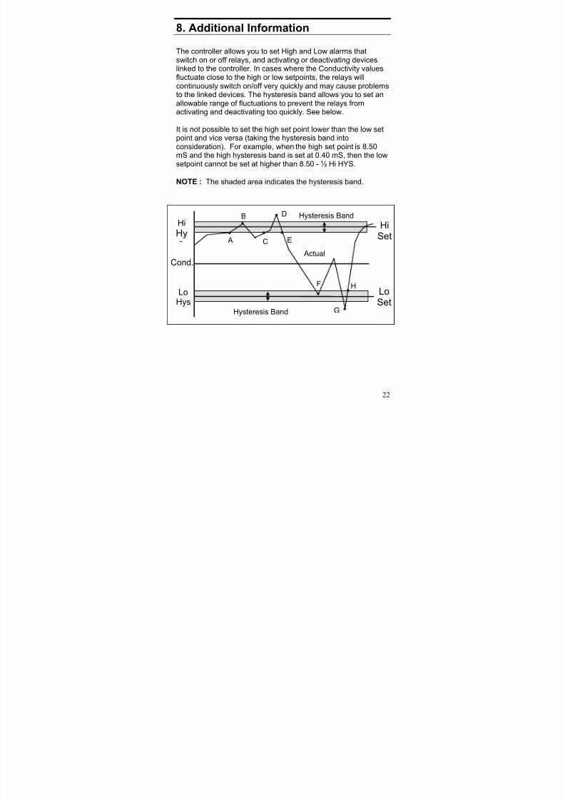
8. Additional Information
The controller allows you to set High and Low alarms thatswitch on or off relays, and activating or deactivating deviceslinked to the controller. In cases where the Conductivity valuesfluctuate close to the high or low setpoints, the relays willcontinuously switch on/off very quickly and may cause problemsto the linked devices. The hysteresis band allows you to set anallowable range of fluctuations to prevent the relays fromactivating and deactivating too quickly. See below.
It is not possible to set the high set point lower than the low set
point and vice versa (taking the hysteresis band intoconsideration). For example, when the high set point is 8.50mS and the high hysteresis band is set at 0.40 mS, then the lowsetpoint cannot be set at higher than 8.50 - ½ Hi HYS.
NOTE : The shaded area indicates the hysteresis band.
Hi
Hy
LoHys
Hysteresis Band
Hysteresis Band
HiSet
LoSet
Cond. Actual
A
B
C
D
E
F
G
H
8/14/2019 Alpha Con 100 Dutch
http://slidepdf.com/reader/full/alpha-con-100-dutch 24/29
23
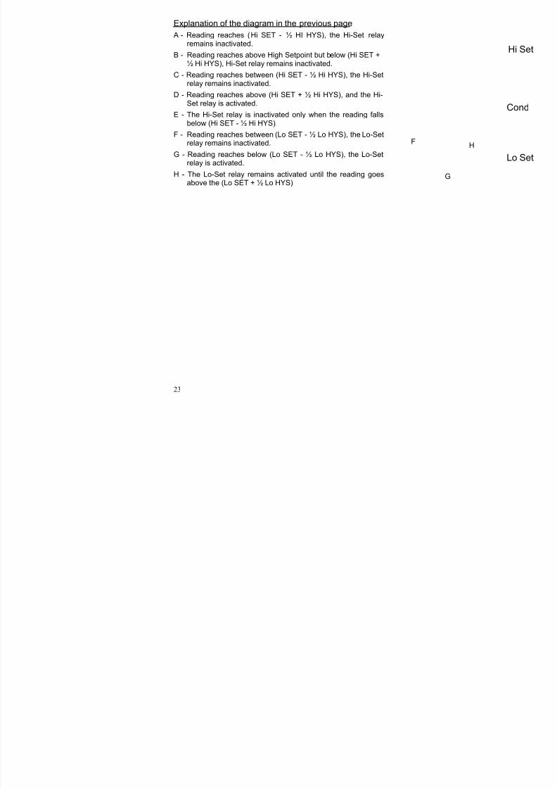
Explanation of the diagram in the previous page
A - Reading reaches (Hi SET - ½ HI HYS), the Hi-Set relayremains inactivated.
B - Reading reaches above High Setpoint but below (Hi SET +½ Hi HYS), Hi-Set relay remains inactivated.
C - Reading reaches between (Hi SET - ½ Hi HYS), the Hi-Setrelay remains inactivated.
D - Reading reaches above (Hi SET + ½ Hi HYS), and the Hi-Set relay is activated.
E - The Hi-Set relay is inactivated only when the reading fallsbelow (Hi SET - ½ Hi HYS).
F - Reading reaches between (Lo SET - ½ Lo HYS), the Lo-Setrelay remains inactivated.
G - Reading reaches below (Lo SET - ½ Lo HYS), the Lo-Setrelay is activated.
H - The Lo-Set relay remains activated until the reading goesabove the (Lo SET + ½ Lo HYS)
Hi Set
Lo Set
Cond
F
G
H

8/14/2019 Alpha Con 100 Dutch
http://slidepdf.com/reader/full/alpha-con-100-dutch 25/29
24
Appendix 1
Jumper Positions - Internal to the Controller
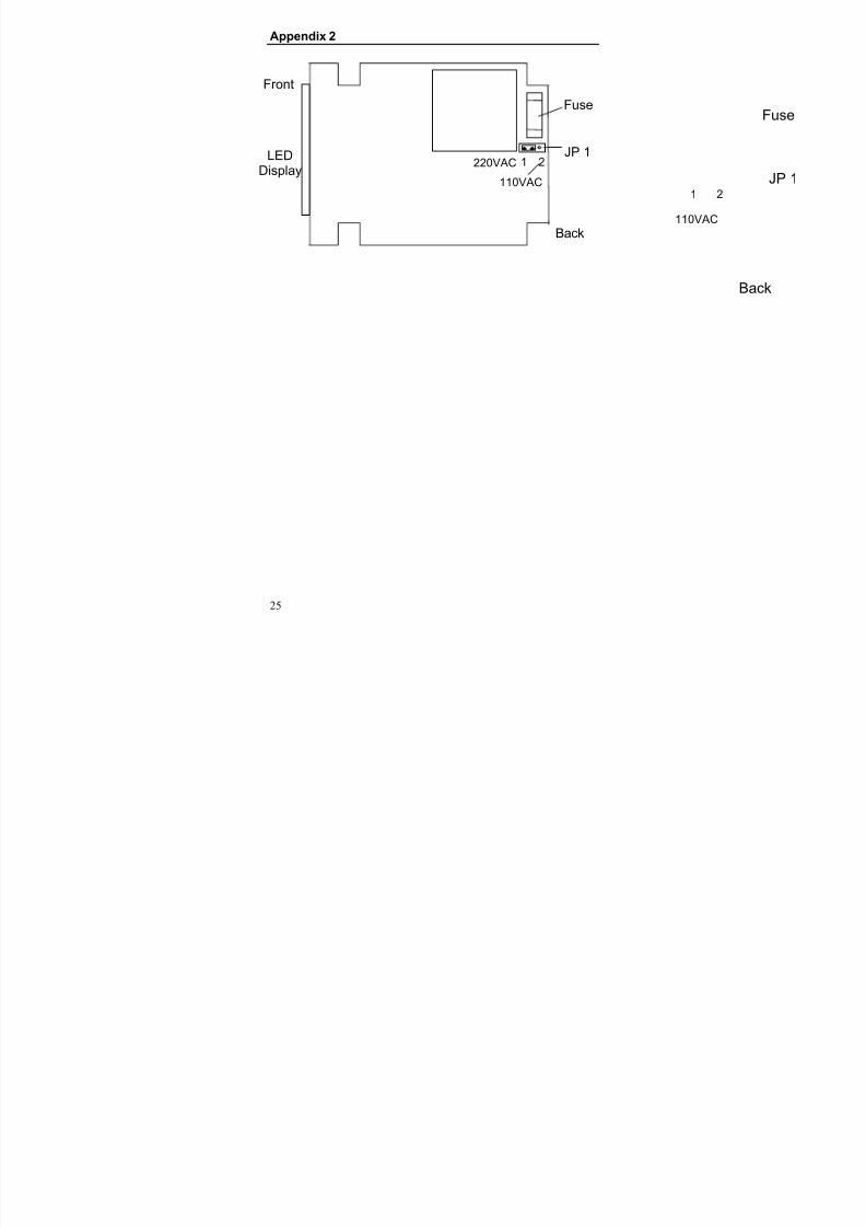
JP1 Selects the input voltage between 110 VAC or 220 VAC.
Fuse Note that there is a fuse internal to theController. Before opening the unit, ENSUREthat the power cable is physically separatedfrom the mains supply. Replace the fuse withthe one recommended by the manufacturer.
8/14/2019 Alpha Con 100 Dutch
http://slidepdf.com/reader/full/alpha-con-100-dutch 26/29
25
Appendix 2
Back
JP 1
Fuse
1 2
110VAC
Front
Back
JP 1
Fuse
1 2LED
Display 220VAC
110VAC

8/14/2019 Alpha Con 100 Dutch
http://slidepdf.com/reader/full/alpha-con-100-dutch 27/29
26
Appendix 3
Temperature Coefficient
The Temperature Coefficients (TC) of most solutions varybetween 1.8 to 2.4 % per
oC. This is true of most salt solutions
when the Conductivity exceeds about 100 uS. Thus, the defaultvalue of TC will be set to 2.10 % per
oC when the Controller is
shipped from the factory. However, if the TemperatureCoefficient is known to be different from the default, the user can set this value.
Temperature Coefficient can also be determined by taking 2
uncompensated readings at known temperatures.Uncompensated readings can be taken by setting TC to 0.0 %or setting the temperature to 25
oC by changing ATC ON to ATC
OFF.
If G1 and G2 are the conductivity measured at twotemperatures T1 and T2, then TC is given by the relation:
% TC = ----------------------------------------
G1(T2 - 25) - G2(T1-25)
G2 - G1
* 100
8/14/2019 Alpha Con 100 Dutch
http://slidepdf.com/reader/full/alpha-con-100-dutch 28/29
27
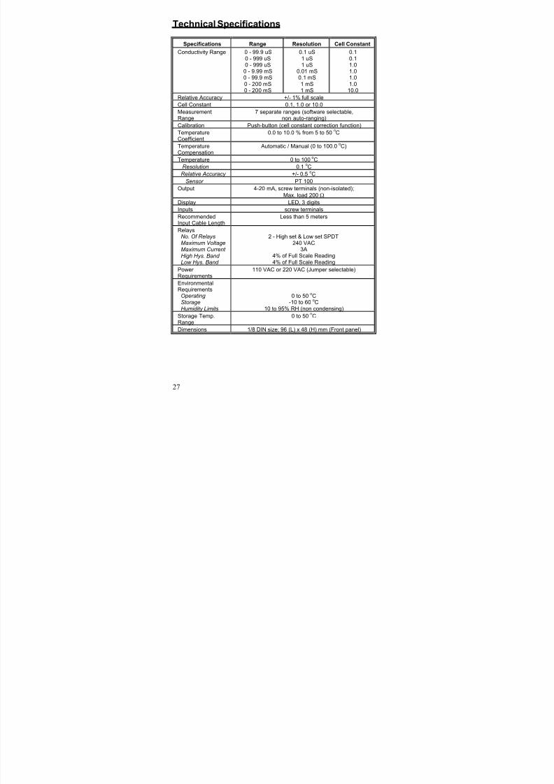
Technical Specifications
Specifications Range Resolution Cell Constant
Conductivity Range 0 - 99.9 uS0 - 999 uS0 - 999 uS
0 - 9.99 mS0 - 99.9 mS0 - 200 mS0 - 200 mS
0.1 uS1 uS1 uS
0.01 mS0.1 mS1 mS1 mS
0.10.11.01.01.01.0
10.0
Relative Accuracy +/- 1% full scale
Cell Constant 0.1, 1.0 or 10.0
MeasurementRange
7 separate ranges (software selectable,non auto-ranging)
Calibration Push-button (cell constant correction function)
Temperature
Coefficient
0.0 to 10.0 % from 5 to 50oC
TemperatureCompensation
Automatic / Manual (0 to 100.0oC)
Temperature 0 to 100oC
Resolution 0.1oC
Relative Accuracy +/- 0.5oC
Sensor PT 100
Output 4-20 mA, screw terminals (non-isolated);
Max. load 200 Ω
Display LED, 3 digits
Inputs screw terminals
RecommendedInput Cable Length
Less than 5 meters
RelaysNo. Of RelaysMaximum VoltageMaximum Current High Hys. Band Low Hys. Band
2 - High set & Low set SPDT240 VAC
3A4% of Full Scale Reading4% of Full Scale Reading
Power
Requirements
110 VAC or 220 VAC (Jumper selectable)
EnvironmentalRequirements
Operating StorageHumidity Limits
0 to 50oC
-10 to 60oC
10 to 95% RH (non condensing)
Storage Temp.Range
0 to 50oC
Dimensions 1/8 DIN size; 96 (L) x 48 (H) mm (Front panel)

8/14/2019 Alpha Con 100 Dutch
http://slidepdf.com/reader/full/alpha-con-100-dutch 29/29
28
NOTES


![Alpha Colonne - Mecano · Alpha Colonne 2,000N at 24V*1 Alpha Colonne 2,000N at 36V*2 Alpha Colonne 3,000N at 24V*1 Alpha Colonne 3,000N at 36V*2 Load [N] Geschwindigkeits - Kraftdiagramm](https://static.fdocuments.nl/doc/165x107/5e88df6a78aa4456b05f26b2/alpha-colonne-mecano-alpha-colonne-2000n-at-24v1-alpha-colonne-2000n-at-36v2.jpg)


![Ben Brooks - Alpha Decay · 2014. 12. 25. · En el mundo anglosajón, Tao Lin [1] (1983), que triunfó con «Richard Ya - tes» y pronto publicará en cas - tellano «Robar en American](https://static.fdocuments.nl/doc/165x107/5fd33e20928815128f4a1576/ben-brooks-alpha-2014-12-25-en-el-mundo-anglosajn-tao-lin-1-1983.jpg)