


Talen
Pages
Wettelijk

2003
1/21
Biomass Energy Utilization & Environment Protection - Commercial Reality and Outlook
Miro R. Susta, IMTE AG Power Consulting Engineers, Switzerland Peter Luby, INGCHEM, Slovak Republic
Dr. Sohif Bin Mat, Transtherm Engineering & Construction Sdn Bhd, Malaysia [email protected] & [email protected]
Abstract Rapid rate at which fossil and residual fuels are releasing CO2 into the atmosphere has raised
international concern and has spurred intensive efforts to develop alternative, renewable,
sources of primary energy.
The solar energy stored in chemical form in plant and animal materials is among the most
precious and most promising alternative fuels not only for power generation but also for other
industrial and domestic applications on earth. It provides not only food but also energy,
building materials, paper, fabrics, medicines and chemicals.
Biomass absorbs the same amount of CO2 in growing that it releases when burned as a fuel in
any form. Biomass contribution to global warming is zero. In addition, biomass fuels contain
negligible amount of sulphur, so their contribution to acid rain is minimal.
Over millions of years, natural processes in the earth transformed organic matter into today's
fossil fuels: oil, natural gas and coal. In contrast, biomass fuels come from organic matter in
trees, agricultural crops and other living plant material.
CO2 from the atmosphere and water from the earth are combined in the photosynthetic
process to produce carbohydrates that form the building blocks of biomass. The solar energy
that drives photosynthesis is stored in the chemical bonds of the structural components of
biomass. If we burn biomass efficiently oxygen from the atmosphere combines with the
carbon in plants to produce CO2 and water. The process is cyclic because the carbon dioxide
is then available to produce new biomass.
Typical biomass resources include:
The forest Waste from wood processing industry Agricultural waste Urban wood waste Wastewater & landfill Other natural resources (straw, peat, bagasse, etc.)
Unlike any other energy resource, using biomass to produce energy is often a way to dispose
of biomass waste materials that otherwise would create environmental risks.
2003
2/21
Today, there are ranges of biomass utilization technologies that produce useful energy from
biomass.
• Direct Combustion • Gasification • Anaerobic Digestion • Methanol & Ethanol Production
There are a number of challenges that inhibit the development of biomass energy. In this
regard, formulation of sustainable energy policy and strategies in addressing these challenges
is indeed a pre-requisite for the development and promotion of biomass energy. Major
available biomass utilization technologies are described and their advantages and
disadvantages are discussed in this paper.
Introduction Rapid rate at which fossil and residual fuels are releasing CO2 into the atmosphere has raised
international concern and has spurred intensive efforts to develop alternative, renewable,
sources of primary energy.
Biomass as the solar energy stored in chemical form in plant and animal materials is among
the most precious and most promising alternative fuels not only for power generation but also
for other industrial and domestic applications on earth.
It provides not only food but also energy, building materials, paper, fabrics, medicines and
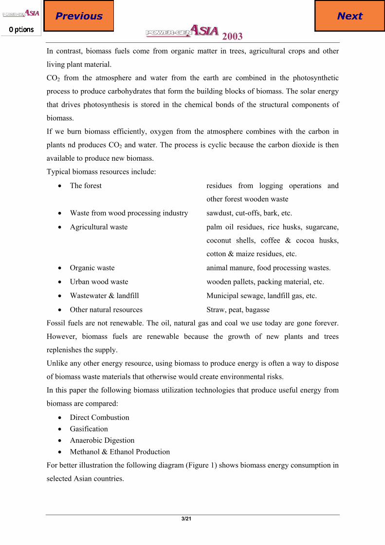
chemicals. Biomass has been used for energy purposes ever since man discovered fire.
It is important to say, that biomass absorbs the same amount of CO2 in growing that it
releases when burned as a fuel in any form. This means that biomass contribution to global
warming is zero. In addition, biomass fuels contain negligible amount of sulphur, so their
contribution to acid rain is minimal.
Over millions of years, natural processes in the earth transformed organic matter into today's
fossil fuels: oil, natural gas and coal.
BIOCYCLE
2003
3/21
In contrast, biomass fuels come from organic matter in trees, agricultural crops and other
living plant material.
CO2 from the atmosphere and water from the earth are combined in the photosynthetic
process to produce carbohydrates that form the building blocks of biomass. The solar energy
that drives photosynthesis is stored in the chemical bonds of the structural components of
biomass.
If we burn biomass efficiently, oxygen from the atmosphere combines with the carbon in
plants nd produces CO2 and water. The process is cyclic because the carbon dioxide is then
available to produce new biomass.
Typical biomass resources include:
• The forest residues from logging operations and
other forest wooden waste
• Waste from wood processing industry sawdust, cut-offs, bark, etc.
• Agricultural waste palm oil residues, rice husks, sugarcane,
coconut shells, coffee & cocoa husks,
cotton & maize residues, etc.
• Organic waste animal manure, food processing wastes.
• Urban wood waste wooden pallets, packing material, etc.
• Wastewater & landfill Municipal sewage, landfill gas, etc.
• Other natural resources Straw, peat, bagasse
Fossil fuels are not renewable. The oil, natural gas and coal we use today are gone forever.
However, biomass fuels are renewable because the growth of new plants and trees
replenishes the supply.
Unlike any other energy resource, using biomass to produce energy is often a way to dispose
of biomass waste materials that otherwise would create environmental risks.
In this paper the following biomass utilization technologies that produce useful energy from
biomass are compared:
• Direct Combustion • Gasification • Anaerobic Digestion • Methanol & Ethanol Production
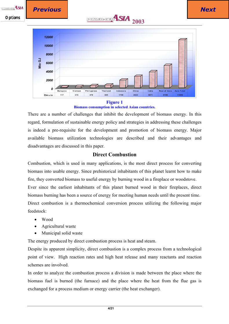
For better illustration the following diagram (Figure 1) shows biomass energy consumption in
selected Asian countries.
2003
4/21
0
2000
4000
6000
8000
10000
12000M
io G
J
M i o GJ 117 315 478 605 1758 2623 3671 5196 11092
M al aysi a V i et nam P hi l i ppi nes T hai l and I ndonesi a Chi na I ndi a Rest of Asi a Asi a T ot al
Figure 1
Biomass consumption in selected Asian countries.
There are a number of challenges that inhibit the development of biomass energy. In this
regard, formulation of sustainable energy policy and strategies in addressing these challenges
is indeed a pre-requisite for the development and promotion of biomass energy. Major
available biomass utilization technologies are described and their advantages and
disadvantages are discussed in this paper.
Direct Combustion Combustion, which is used in many applications, is the most direct process for converting
biomass into usable energy. Since prehistorical inhabitants of this planet learnt how to make
fire, they converted biomass to useful energy by burning wood in a fireplace or woodstove.
Ever since the earliest inhabitants of this planet burned wood in their fireplaces, direct
biomass burning has been a source of energy for meeting human needs until the present time.
Direct combustion is a thermochemical conversion process utilizing the following major
feedstock:
• Wood • Agricultural waste • Municipal solid waste
The energy produced by direct combustion process is heat and steam.
Despite its apparent simplicity, direct combustion is a complex process from a technological
point of view. High reaction rates and high heat release and many reactants and reaction
schemes are involved.
In order to analyze the combustion process a division is made between the place where the
biomass fuel is burned (the furnace) and the place where the heat from the flue gas is
exchanged for a process medium or energy carrier (the heat exchanger).
2003
5/21
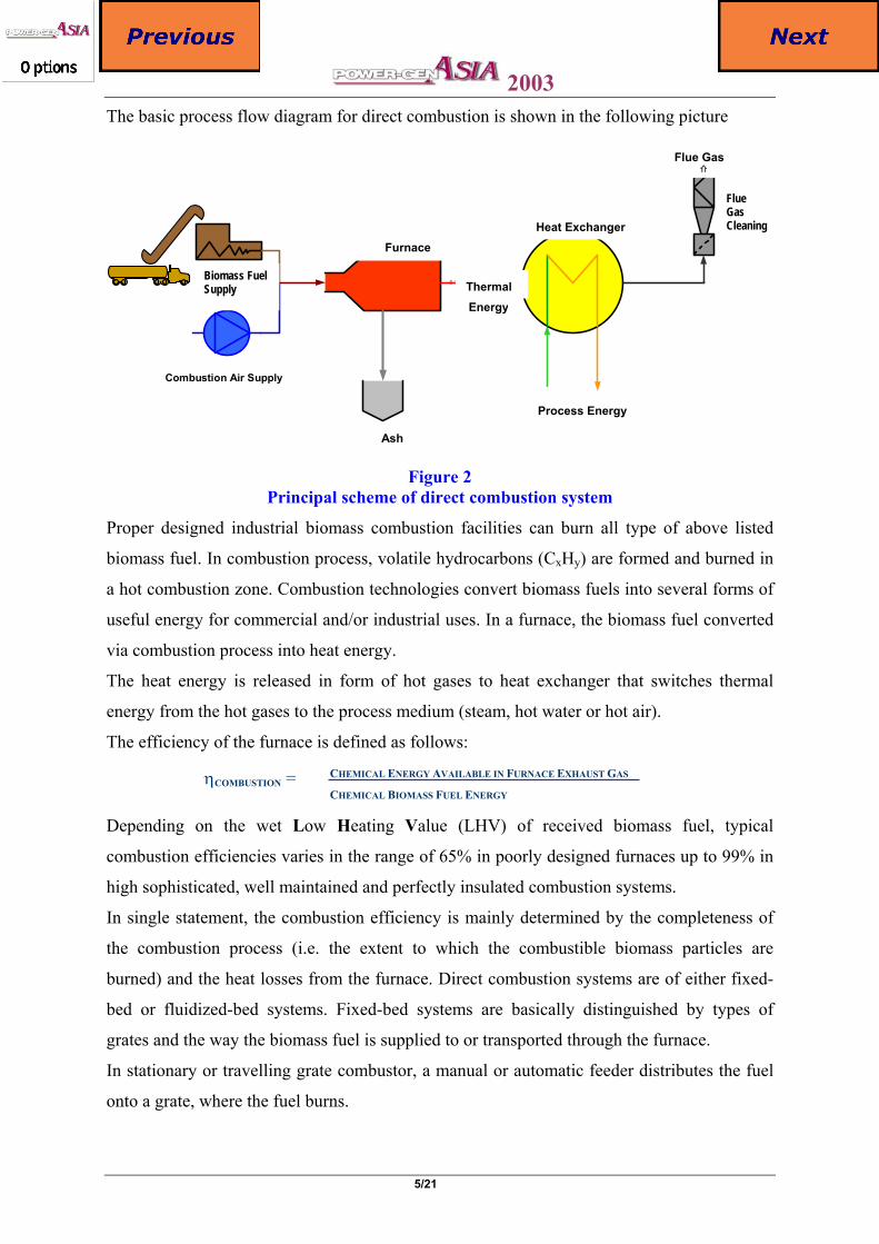
The basic process flow diagram for direct combustion is shown in the following picture
Combustion Air Supply
E-3
E-6
ThermalEnergy
Heat Exchanger
Process Energy
Furnance
Ash
Biomass Fuel Supply
Flue Gas
Flue Gas
Cleaning
Figure 2
Principal scheme of direct combustion system
Proper designed industrial biomass combustion facilities can burn all type of above listed
biomass fuel. In combustion process, volatile hydrocarbons (CxHy) are formed and burned in
a hot combustion zone. Combustion technologies convert biomass fuels into several forms of
useful energy for commercial and/or industrial uses. In a furnace, the biomass fuel converted
via combustion process into heat energy.
The heat energy is released in form of hot gases to heat exchanger that switches thermal
energy from the hot gases to the process medium (steam, hot water or hot air).
The efficiency of the furnace is defined as follows:
CHEMICAL ENERGY AVAILABLE IN FURNACE EXHAUST GAS ηCOMBUSTION = CHEMICAL BIOMASS FUEL ENERGY
Depending on the wet Low Heating Value (LHV) of received biomass fuel, typical
combustion efficiencies varies in the range of 65% in poorly designed furnaces up to 99% in
high sophisticated, well maintained and perfectly insulated combustion systems.
In single statement, the combustion efficiency is mainly determined by the completeness of
the combustion process (i.e. the extent to which the combustible biomass particles are
burned) and the heat losses from the furnace. Direct combustion systems are of either fixed-
bed or fluidized-bed systems. Fixed-bed systems are basically distinguished by types of
grates and the way the biomass fuel is supplied to or transported through the furnace.
In stationary or travelling grate combustor, a manual or automatic feeder distributes the fuel
onto a grate, where the fuel burns.
Combustion Air Supply
Biomass Fuel Supply
Ash
Furnace
ThermalEnergy
Process Energy
Heat Exchanger
Flue Gas ⇑
Flue Gas Cleaning
2003
6/21
Combustion air enters from below the grate. In the stationary grate design, ashes fall into a pit
for collection. In contrast, a travelling grate system has a moving grate that drops the ash into
a hopper.
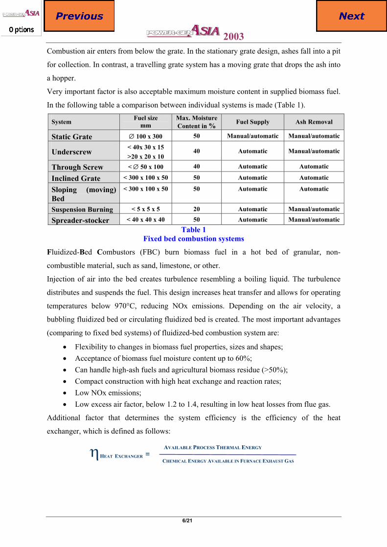
Very important factor is also acceptable maximum moisture content in supplied biomass fuel.
In the following table a comparison between individual systems is made (Table 1).
System Fuel size mm
Max. Moisture Content in % Fuel Supply Ash Removal
Static Grate ∅ 100 x 300 50 Manual/automatic Manual/automatic
Underscrew < 40x 30 x 15 >20 x 20 x 10
40 Automatic Manual/automatic
Through Screw < ∅ 50 x 100 40 Automatic Automatic
Inclined Grate < 300 x 100 x 50 50 Automatic Automatic
Sloping (moving) Bed
< 300 x 100 x 50 50 Automatic Automatic
Suspension Burning < 5 x 5 x 5 20 Automatic Manual/automatic
Spreader-stocker < 40 x 40 x 40 50 Automatic Manual/automatic Table 1
Fixed bed combustion systems
Fluidized-Bed Combustors (FBC) burn biomass fuel in a hot bed of granular, non-
combustible material, such as sand, limestone, or other.
Injection of air into the bed creates turbulence resembling a boiling liquid. The turbulence
distributes and suspends the fuel. This design increases heat transfer and allows for operating
temperatures below 970°C, reducing NOx emissions. Depending on the air velocity, a
bubbling fluidized bed or circulating fluidized bed is created. The most important advantages
(comparing to fixed bed systems) of fluidized-bed combustion system are:
• Flexibility to changes in biomass fuel properties, sizes and shapes; • Acceptance of biomass fuel moisture content up to 60%; • Can handle high-ash fuels and agricultural biomass residue (>50%); • Compact construction with high heat exchange and reaction rates; • Low NOx emissions; • Low excess air factor, below 1.2 to 1.4, resulting in low heat losses from flue gas.
Additional factor that determines the system efficiency is the efficiency of the heat
exchanger, which is defined as follows:
AVAILABLE PROCESS THERMAL ENERGY ηHEAT EXCHANGER = CHEMICAL ENERGY AVAILABLE IN FURNACE EXHAUST GAS
2003
7/21
Typical heat exchanger efficiencies based on biomass LHV range between 60% and 95%,
mainly depending on design and kind of operation and maintenance. The main losses are in
the hot flue gas exiting from the stack.
In the industrial practice, the furnace and heat exchanger form together biomass-fired boiler
unit. The boiler is a more adaptable direct combustion technology because the boiler transfers
the heat of combustion directly into the process medium. Overall boiler efficiency is defined
as follows:
ηBOILER = ηCOMBUSTION x ηHEAT EXCHANGER
Overall boiler efficiency varies between 50% and 95%.
Very common and most efficient are biomass systems with direct combustion for electrical
power generation and co-generation. Such system can achieve an overall efficiency between
30% (power generation systems) and 85% (co-generation systems).
Two cycles are possible for combining electric power generation with process steam
production. Steam can be used in process first and then re-routed through a steam turbine to
generate electric power. This arrangement is called a bottoming cycle.
In the alternate cycle, steam from the boiler passes first through a steam turbine to produce
electric power.
The back-pressure (or extracted) steam from the steam turbine is then used for processes or
for heating (or cooling) purposes. This arrangement is called a topping cycle, which the more
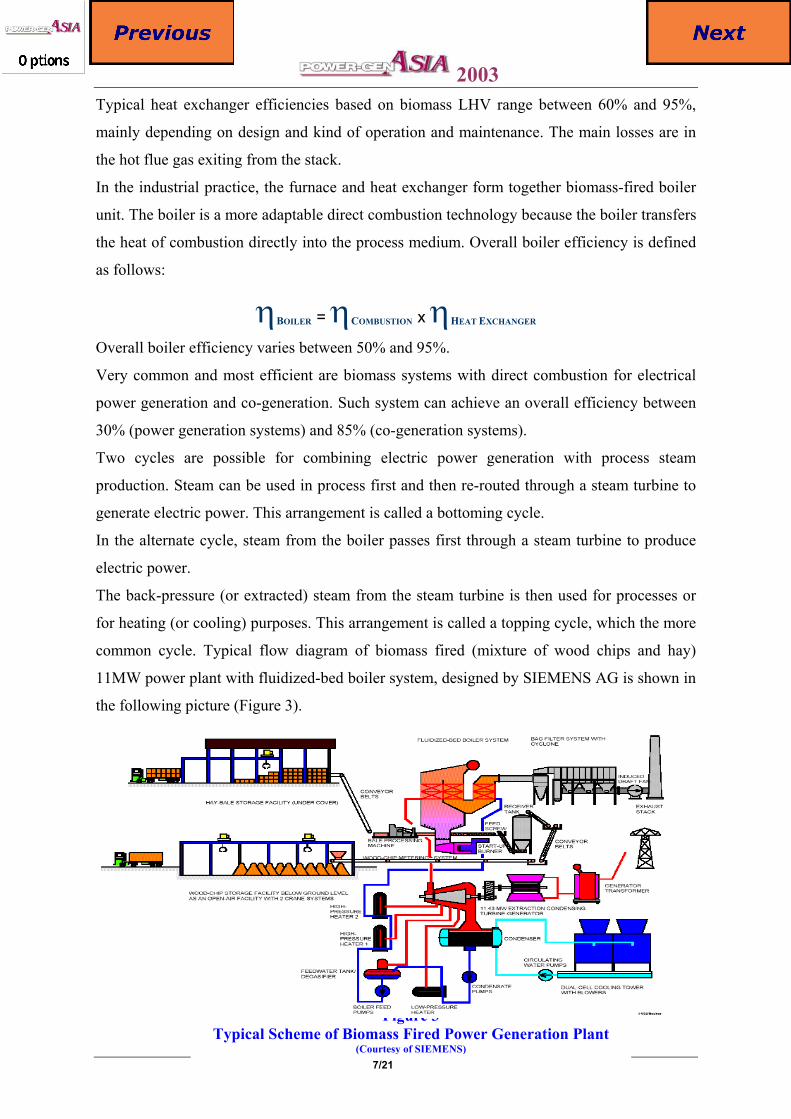
common cycle. Typical flow diagram of biomass fired (mixture of wood chips and hay)
11MW power plant with fluidized-bed boiler system, designed by SIEMENS AG is shown in
the following picture (Figure 3).
Figure 3 Typical Scheme of Biomass Fired Power Generation Plant
(Courtesy of SIEMENS)
2003
8/21
More efficient co-generation system based on above shown steam cycle is very easy to
design. Instead of condensing steam turbine a backpressure steam turbine can be applied,
delivering steam at required process conditions. Another possibility is a combination of
condensing steam turbine with controlled steam extraction facilities. This alternative offers
maximum flexibility, i.e. during low process steam demand period maximum electric power
can be generated.
Up to the present time, many biomass fired co-generation power plants have been built
worldwide, replacing low efficient heat-only boilers.
Biomass Gasification Systems Gasification, production of combustible gas from carbon containing materials, is already an
old technology. The first record of its commercial application origins from so called dry
distillation (or pyrolysis – heating of feedstock on absence of O2, resulting in thermal
decomposition of fuel into volatile gases and solid carbon) origins from year 1812 (Gas
Company in London).
The first commercial gasifier for continuous air-blown gasification of solid fuels was
installed in 1839. Later, gas industry producing gas from coal and biomass was established.
The first attempt to use producer gas to fire the internal combustion engine was carried out in
1881.
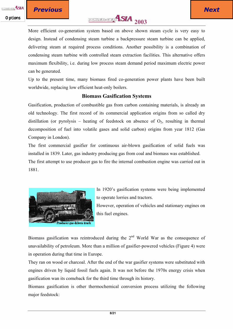
In 1920’s gasification systems were being implemented
to operate lorries and tractors.
However, operation of vehicles and stationary engines on
this fuel engines.
Biomass gasification was reintroduced during the 2nd World War as the consequence of
unavailability of petroleum. More than a million of gasifier-powered vehicles (Figure 4) were
in operation during that time in Europe.
They ran on wood or charcoal. After the end of the war gasifier systems were substituted with
engines driven by liquid fossil fuels again. It was not before the 1970s energy crisis when
gasification wan its comeback for the third time through its history.
Biomass gasification is other thermochemical conversion process utilizing the following
major feedstock:
Figure 4
2003
9/21
• Wood • Agricultural waste • Municipal solid waste
Chemical process of gasification means the thermal decomposition of hydrocarbons from
biomass in a reducing (oxygen-deficient) atmosphere. The process usually takes place at
about 850ºC. Because the injected air prevents the ash from melting, steam injection is not
always required. A biomass gasifier can operate under atmospheric pressure or elevated
pressure.
If the fuel gas is generated for combustion in the gas turbine (Figure 5) the pressure of
gasification is always super-atmospheric.
The resulting gas product, the syngas, contains combustible gases – hydrogen (H2) and
carbon monoxide (CO) as the main constituents.
By-products are liquids and tars, charcoal and mineral matter (ash or slag). Reducing
atmosphere of the gasification stage means that only 20% to 40% of stochiometric amount of
oxygen (O2) related to a complete combustion enters the reaction.
This is enough to cover the heat energy necessary for a complete gasification. Say in other
words, the system is autothermic.
It creates sensible heat necessary to complete gasification from its own internal resources.
Prevailing chemical reactions are listed in Table 2, where the following main three
gasification stages are described.
Stage I Gasification process starts as autothermal heating of the reaction mixture. The
necessary heat for this process is covered by the initial oxidation exothermic
reactions by combustion of a part of the fuel (refer to Table 2).
Stage II In the second – pyrolysis stage, combustion gases are pyrolyzed by being
passed through a bed of fuel at high temperature. Heavier biomass molecules
distillate into medium weight organic molecules and CO2, through reactions
(8) and (9). In this stage, tar and char are also produced.
Stage III Initial products of combustion, carbon dioxide (CO2) and (H2O) are
reconverted by reduction reaction to carbon monoxide (CO), hydrogen (H2) and
methane (CH4).
These are the main combustible components of syngas. These reactions, not necessarily
related to reduction, occurre at high temperature. Gasification reactions (10-13), most
important for the final quality (heating value) of syngas, take place in the reduction zone of
the gasifier.
2003
10/21
Heat consumption prevails in this stage and the gas temperature will therefore decrease. Tar
is mainly gasified, while char, depending upon the technology used, can be significantly
"burned" through reactions (10) and (11), reducing the concentration of particulates in the
product.
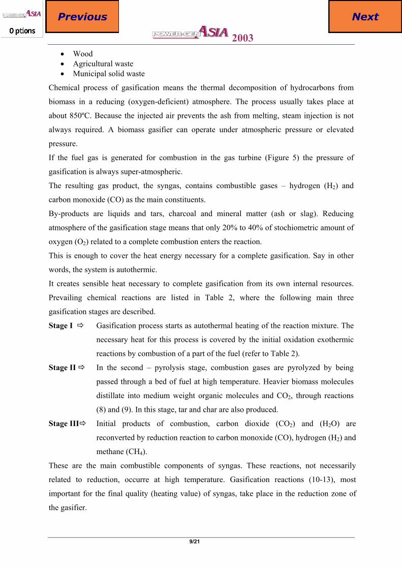
Gasification Stage Reaction formula (Reaction number) /
Reaction type Reaction heat
kJ/kmol C+½O2 CO (1) Partial oxidation +110,700 CO+½ O2 CO2 (2) CO oxidation +283,000 C+O2 CO2 (3) Total oxidation +393,790 C6 H10 O5 xCO2+yH2O (4) Total oxidation >>0 H2+½O2 H2O (5) Hydrogen oxidation +241,820 CO+H2O CO2+H2 (6) Water-gas shift + 41,170
Stage I Oxidation and other exothermic reactions
CO+3H2 CH4+H2O (7) Methanation +206,300 C6H10O5 CxHz+ CO (8) Pyrolysis <0 Stage II
Pyrolysis C6H10O5 CnHmOy (9) Pyrolysis <0 C+H2O CO+H2 (10) Steam gasification -131,400 C+CO2 2CO (11) Boudouard reaction -172,580 CO2+H2 CO+H2O (12) Reverse water shift - 41,170
Stage III Gasification (Reduction)
C+2H2 CH4 (13) Hydrogenation + 74,900
Table 2 Three main successive stages of biomass gasification.
Source: J.B. Jones & G.A. Hawkins: Engineering Thermodynamics, 1986, p. 456 Gasification is accompanied by chemical reactions that proceed at high temperature with
gasifying agent and (occasionally) with steam as moderating agent.
In general, the gasifying agent can be air, oxygen (O2) or oxygen-enriched air. For biomass
gasification, air is normally used as oxidant (oxygen as the oxidant agent is preferred in high-
capacity fossil fuel gasification systems).
The net product of air gasification can be found by summing up the partial reactions, as
follows:
Carbohydrate matter (C6H10O5)+O2 CXHY+CLHMON+CO+H2+Heat
Reactions labelled in Table 2 with positive value of reaction heat are exothermic (chemical
energy is converted to sensible heat). Reactions with the negative sign are on contrary
endothermic (heat is consumed in favour of chemical energy).
Gasifiers are designed according to the origin and quality of fuel and the method in which the
fuel is brought to contact with the oxidant. According to the fuel gas end use, the gasifier
types can be divided into
• Heat gasifiers - used for fuelling external burners in boilers or dryers; and
• power gasifiers - coupled to gas turbine or internal combustion engine for power
generation
2003
11/21
Additionally, apart from being categorized according to heat or power generation purposes,
gasifiers can be classified as
• entrained bed • fluidised bed • fixed bed
Entrained Bed Gasifiers (EBG) are high-capacity design apparates. They require perfect
atomisation of feedststock (0.1mm) and therefore are not suitable for biomass gasification.
Fluidised Bed Gasifiers (FBG) can be divided into Bubbling (BFBG) and Circulating
(CFBG) gasifiers. BFBG give a good temperature control and high conversion rates, good
scale-up-potential, possibility of in-bed catalytic processing.
They are not sensitive to particle size and to fluctuations in feed quantity and moisture.
Product gas generated by BFGB has low tar content. Their drawback is high content of
particulates. CFBG are suitable for fuel capacity higher than 10 MWth. Compared to BFBG,
they have the additional advantage of giving high gas quality.
Fixed bed gasifiers are the most suitable for biomass gasification. Three possible designs of
fixed bed gasifiers exist, namely
• Down-draft (or co-current) • Updraft (or counter-current) • Crossdraft (or cross current) • Open core (open current)
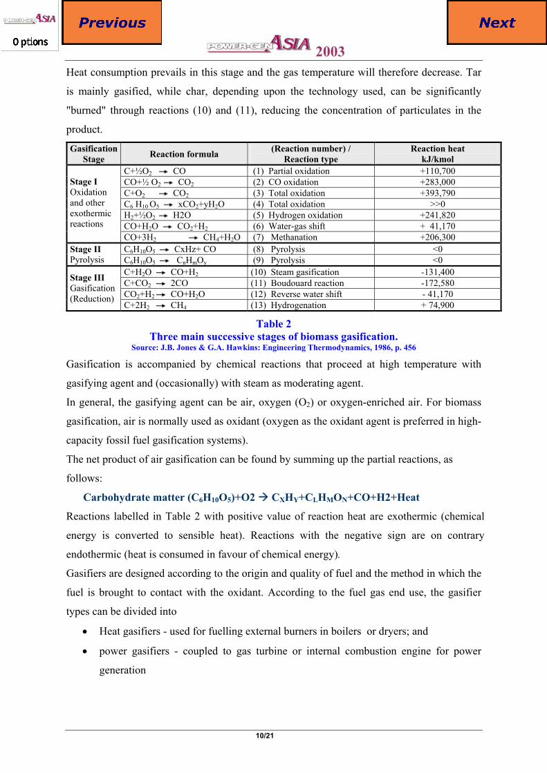
All gasifiers have strict fuel requirements to size, moisture and ash content. The typical
characteristics of some biomass fuels can be summarised as presented in the Table 3.
Biomass Fuel Moisture % wet
Ash % dry
Volatile Matter % dry
Bulk density kg/m3
Average HHV MJ/kg dry
Charcoal 2-10 2-5 5-30 200-300 30 Wood 20-40 0.1-1.0 70-80 600-800 20 Rice Husks 3-5 15-25 60 100 15 Coconut Shells 25 0.8 79 not available 20
Table 3 Typical characteristics of biomass fuels for gasification
A generalised overview of the most important fuel requirements for different type of
gasifiers, are presented in Table 4. Gasifier Type Updraft Downdraft Open Core Cross draft Fuel Wood Wood Rice Husks Charcoal Size, mm 20-100 5-100 1-3 40-80 Moisture, % <25 <60 <12 <7 Ash, % <6 <25 Approx. 20 <6
Table 4 Fuel requirements for different gasifier types
2003
12/21
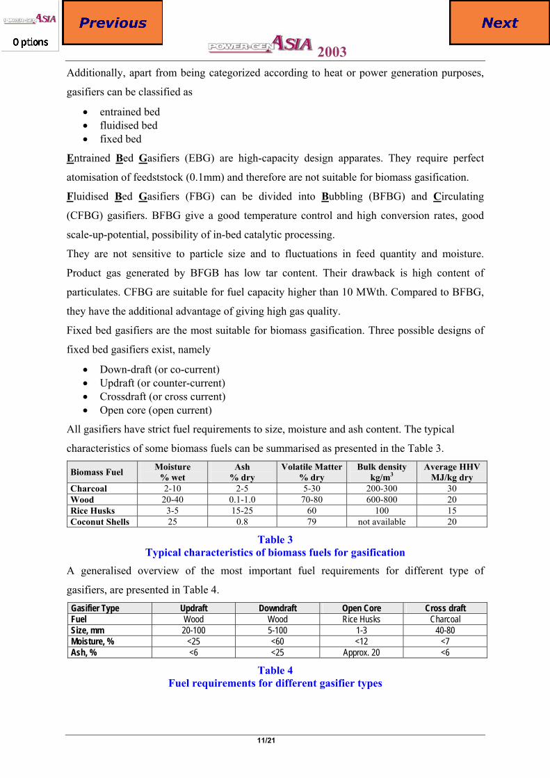
The biggest advantage of gasification is the variety of feedstocks as well as products. The
produced syngas can be utilized not only as the fuel for power generation but also as the
feedstock for chemical industry.
Final products of synthesis can be various chemicals, hydrogen, ammonia, methanol, as
indicated in Figure 5.
Figure 5 Downdraft entrained-flow Texaco gasifier.
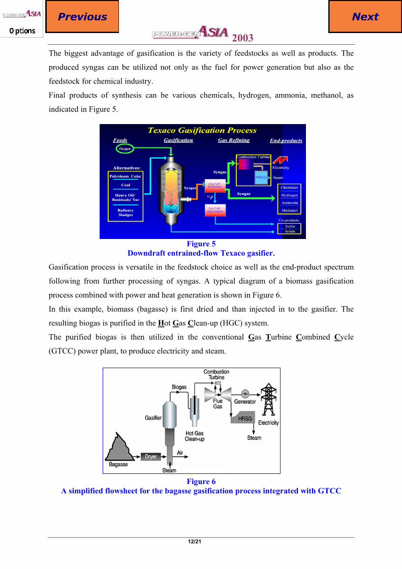
Gasification process is versatile in the feedstock choice as well as the end-product spectrum
following from further processing of syngas. A typical diagram of a biomass gasification
process combined with power and heat generation is shown in Figure 6.
In this example, biomass (bagasse) is first dried and than injected in to the gasifier. The
resulting biogas is purified in the Hot Gas Clean-up (HGC) system.
The purified biogas is then utilized in the conventional Gas Turbine Combined Cycle
(GTCC) power plant, to produce electricity and steam.
Figure 6
A simplified flowsheet for the bagasse gasification process integrated with GTCC
2003
13/21
Advanced integrated biomass gasification and combined heat and power concepts are
promising but still not fully demonstrated. The main difficulties are the requirements set by
gas turbine manufacturers in adapting gas turbines to low BTU gases and to fulfil the gas
quality specifications applicable for syngas utilization in gas turbines.
Anaerobic Digestion – Biogas & Landfill Gas As per records, Alessandro Volta first discovered biogas in 1776 and Humphery Davy was
the first to pronounce the presence of combustible gas Methane in the Farmyard Manure in as
early as 1800.
Anaerobic digestion is a biological process that produces a gas principally composed of
methane (CH4) and carbon dioxide (CO2) otherwise known as biogas. The biogas is produced
from the following major organic wastes:
• Solid & liquid animal manure • Agricultural plant waste • Waste from agricultural products processing industry • Organic components in town waste • Waste waters • Landfills
Biogas occurs naturally, hence its name, amongst others in swamps and lakes when
conditions are right.
Anaerobic digestion can be used to produce valuable energy from waste streams of natural
materials or to lower the pollution potential of a waste stream.
The biogas-production will normally be in the range of 0.3 - 0.45 m3 of biogas per kg of solid
substances for a well functioning process with a typical retention time of 20-30 days. The
lower heating value of this gas is about 22 MJ/m3.
Biogas plant has a self-consumption of energy to keep the sludge warm. This is typically 20%
of the energy production for a well-designed biogas plant.
For example if the biogas is used for power and co-generation, the available electricity will
be 30-40% of the energy in the biogas, the heat will be 40-50% and the remaining 20% will
be said self-consumption.
Anaerobic digestion is a complex biochemical reaction carried out in a number of steps by
several types of microorganisms that require little or no oxygen to live.
During the process a biogas, principally composed of approximately 65% methane (CH4) and
about 30% carbon dioxide (CO2), is produced.
The amount of biogas produced varies with the amount of organic waste fed to the digester
and temperature influences the rate of decomposition
2003
14/21
Several different types of bacteria work in stages together, to break down complex organic
wastes, resulting in the production of biogas.
Controlled anaerobic digestion requires an airtight chamber, called a digester.
To promote bacterial activity, the digester must maintain a temperature of at least 20°C (ideal
25°C - 35°C). Higher digester temperatures, above 50°C - 65°C, shorten processing time, allowing
the digester to handle a larger volume of organic waste.
A mixture of CH4 with CO2 is making up more than 90% of the total biogas composition. The
remaining gases are usually smaller amounts of H2S, N, H2, methylmercaptans and O.
The biogas energy content depends on the amount of CH4 it contains. Biogas CH4 content varies
from about 55% to 80%. Typical biogas, with a CH4 concentration of 65%, contains about 22
MJ/Nm3 of energy, which is equivalent to 0.55 kg of light diesel oil.
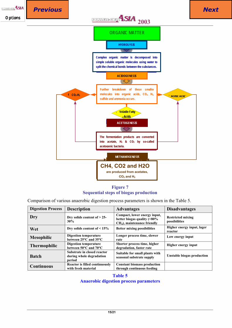
The process of biological anaerobic digestion occurs in a sequence of steps involving distinct
types of bacteria as illustrated in Figure 7.
The acetogenic bacteria grow in close association with the methanogenic bacteria during the last
stage of the process. The reason for this is that the conversion of the fermentation products by the
acetogens is thermodynamically only possible if the hydrogen concentration is kept sufficiently
low. This process only takes place under strict absence of oxygen.
The combustion of biogas can supply useful energy in the form of steam, hot water or hot air.
After filtering and drying, biogas is suitable as fuel for an internal combustion engine.
Future applications of biogas may include electric power production from gas turbines or fuel
cells.
Biogas can substitute for natural gas or propane in space heaters, refrigeration equipment, cooking
stoves or other equipment. Compressed digester gas can be used as an alternative transportation
fuel.
Other very important factors for proper anaerobic digestion process are the residence time and
acidity (pH-value).
Residence time has to be well balanced and optimized. The longer a substrate is kept under proper
reaction conditions the more complete its degradation will become.
But the reaction rate will decrease with increasing residence time. Longer residence time requires
automatically larger reactor for a given amount of substrate to be treated.
Shorter residence leads to a higher production rate per reactor volume unit, but a lower overall
degradation.
2003
15/21
ORGANIC MATTER
HYDROLYSIS
Complex organic matter isdecomposed into simplesoluble organic moleculesusing water to split thechemical bonds between thesubstances.
ACIDOGENESIS
Further breakdown of thesesmaller molecules into organicacids, CO 2, H2, sulfide andammonia occurs.
CO2 & H2 Acetic Acid
Volatile FattyAcids
ACETOGENESIS
The fermentation products areconverted into acetate, H2& CO2 by so-called acetogenicbacteria.
METHANOGENESIS
CH4, CO2 and H2O are produced from the acetates,
CO 2 and H2
Figure 7 Sequential steps of biogas production
Comparison of various anaerobic digestion process parameters is shown in the Table 5.
Digestion Process Description Advantages Disadvantages
Dry Dry solids content of > 25-30%
Compact, lower energy input, better biogas quality (<80% CH4), maintenance friendly
Restricted mixing possibilities
Wet Dry solids content of < 15% Better mixing possibilities Higher energy input, lager reactor
Mesophilic Digestion temperature between 25°C and 35°C
Longer process time, slower rate
Low energy input
Thermophilic Digestion temperature between 50°C and 70°C
Shorter process time, higher degradation, faster rate
Higher energy input
Batch Substrate in closed reactor during whole degradation period
Suitable for small plants with seasonal substrate supply Unstable biogas production
Continuous Reactor is filled continuously with fresh material
Constant biomass production through continuous feeding
Table 5 Anaerobic digestion process parameters
ORGANIC MATTER
HYDROLYSIS
Complex organic matter is decomposed intosimple soluble organic molecules using water tosplit the chemical bonds between the substances.
ACIDOGENESIS
Further breakdown of these smallermolecules into organic acids, CO2, H2,sulfide and ammonia occurs.
Acetic Acid CO2-H2
Volatile Fatty Acids
ACETOGENESIS
The fermentation products are convertedinto acetate, H2 & CO2 by so-calledacetogenic bacteria.
METHANOGENESIS
CH4, CO2 and H2O are produced from acetates,
CO2 and H2
2003
16/21
Acidity (pH-value) is other very important factor for bacteria digestion process. It is important to
balance the acidity in reactor in such way that the bacteria become most productive.
Unfortunately, for the different groups of bacteria the optimum acidity is not the same. The
complexity of the entire system is increased by the fact that the intermediate products of the
digestion have a tendency to lower the acidity, making the later steps in the process more difficult.
The same anaerobic digestion process that produces biogas occurs naturally underground in
landfills.
Most landfill gas results from the decomposition of cellulose contained in municipal and industrial
solid waste.
Unlike above motioned anaerobic digesters, which control the anaerobic digestion process, the
digestion occurring in landfills is an uncontrolled process of biomass decay.
The efficiency of the process depends on the waste composition and moisture content of the
landfill, cover material, temperature and other factors.
The biogas released from landfills, commonly called "landfill gas," is typically 50% CH4 and
45% CO2. Remaining 5% are usually other gases like H2S, N, H2 and O.
In theory, the lifetime yield of a good site should lay in the range 150-300 m3 of gas per tonne of
wastes.
This offers a total energy of 5-6 GJ per tonne of waste, but in practice yields are much less.
Capturing landfill gas before it escapes to the atmosphere allows for conversion to useful energy.
The gas is collected by an array of interconnected perforated pipes buried at depths up to 20
metres in the waste.
In new sites this pipe system is constructed before the wastes start to arrive, and in a large well-
established landfill there can be several miles of pipes, with as much as 1000 m3 an hour of gas
being pumped out.
A landfill must be at least 12m deep and have at least one million tons of waste in place for
landfill gas collection and power production to be technically feasible.
Combination of landfill gas capturing with power generation, landfill gas to energy system, is
shown in Figure 8.
A piping system connects the wells and collects the gas. Dryers remove moisture from the gas,
and filters remove impurities.

2003
17/21
Another source of biogas is hidden in organic waste and municipal sewage.
Biomass that is high in moisture content, such as sewage, animal manure and food-processing
wastes, is suitable for producing biogas using anaerobic digester technology.
Many municipal wastewater treatment plants use anaerobic digestion to reduce the volume of the
biomass sludge in sewage.
Sludge digestion produces biogas containing between 60% and 70% HC4, with an average energy
content of about 22 MJ/m3.
Average digestion retention time is 80 days at 20°C and 20 days at 50°C, i.e. proper waste heat
utilization from the process to warm the slurry in the digester reduces retention time considerably.
Ethanol Starch content of Biomass feedstocks like corn, potatoes, beets, sugarcane, wheat, barley, and
similar can be converted by fermentation process into alcohol (ethanol).
Fermentation is the biochemical process that converts sugars into ethanol (alcohol). In contrast to
biogas production, fermentation takes place in the presence of air and is, therefore, a process of
aerobic digestion.
Ethanol producers use specific types of enzymes to convert starch crops such as corn, wheat and
barley to fermentable sugars. Some crops, such as sugar cane and sugar beets, naturally contain
fermentable sugars.
Figure 8 Power Generation from Landfill Gas
The gas typically fuels a boiler to produce heat (steam, hot water, etc.) or gas turbine to produce
electricity. Further gas cleanup improves biogas to pipeline quality, the equivalent of natural gas.
Reforming the gas to hydrogen would make possible the production of electricity using fuel cell
technology.
2003
18/21
Ethanol may also be used as a hydrogen source for fuel cells. Because ethanol is easier to
transport and store than hydrogen, fuel reforming (using a chemical process to extract hydrogen
from fuel) may be a practical way to provide hydrogen to fuel cells in vehicles or for remote
stationary applications.
Latin America, dominated by Brazil, is the world’s largest production region of bioethanol.
Alcohol fuels have also been aggressively pursued in a number of African countries currently
producing sugar - Kenya, Malawi, South Africa and Zimbabwe. Others with great potential
include Mauritius, Swaziland and Zambia.
In developing countries interest in alcohol fuels has been mainly due to low sugar prices in the
international market, and also for strategic reasons. In the industrialized countries, a major reason
is increasing environmental concern, and also the possibility of solving some wider socio-
economic problems, such as agricultural land use and food surpluses. As the value of bioethanol is
increasingly being recognized, more and more policies to support development and
implementation of ethanol as a fuel are being introduced.
Methanol Production of methanol (wood alcohol) from biomass is a thermochemical conversion process.
Potential feedstock includes wood and agricultural residues.
However, nearly all methanol produced today is made from natural gas, thus, will not be
considered in this paper.
In addition, there is a growing consensus that methanol does not have all the environmental
benefits that are commonly sought for oxygenates and which can be fulfilled by ethanol.
Commercial Aspects Direct combustion, gasification as well as anaerobic digestion systems are commercially available.
Direct combustion most advanced concepts based on fluidized bed combustion are technically
proven.
Even though that gasification systems are also commercially available, they are less reliable and
need more supervision in comparison to direct combustion.
The further development should be directed towards improving their performance and reliability.
Anaerobic digestion is very wide used common method for biogas generation, mainly from
sewage, landfills and from waste produced in medium and large farms.
2003
19/21
The economy of a biogas plant consists of large investments costs, some operation and
maintenance costs, mostly free raw materials, and income from sale of biogas or electricity and
heat. Sometimes can be added other values e.g. for improved value of sludge as a fertilizer.
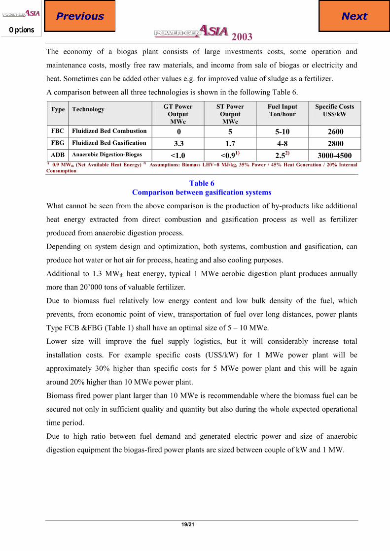
A comparison between all three technologies is shown in the following Table 6.
Type Technology GT Power Output MWe
ST Power Output MWe
Fuel Input Ton/hour
Specific Costs US$/kW
FBC Fluidized Bed Combustion 0 5 5-10 2600 FBG Fluidized Bed Gasification 3.3 1.7 4-8 2800 ADB Anaerobic Digestion-Biogas <1.0 <0.91) 2.52) 3000-4500
1) 0.9 MWth (Net Available Heat Energy) 2) Assumptions: Biomass LHV=8 MJ/kg, 35% Power / 45% Heat Generation / 20% Internal Consumption
Table 6 Comparison between gasification systems
What cannot be seen from the above comparison is the production of by-products like additional
heat energy extracted from direct combustion and gasification process as well as fertilizer
produced from anaerobic digestion process.
Depending on system design and optimization, both systems, combustion and gasification, can
produce hot water or hot air for process, heating and also cooling purposes.
Additional to 1.3 MWth heat energy, typical 1 MWe aerobic digestion plant produces annually
more than 20’000 tons of valuable fertilizer.
Due to biomass fuel relatively low energy content and low bulk density of the fuel, which
prevents, from economic point of view, transportation of fuel over long distances, power plants
Type FCB &FBG (Table 1) shall have an optimal size of 5 – 10 MWe.
Lower size will improve the fuel supply logistics, but it will considerably increase total
installation costs. For example specific costs (US$/kW) for 1 MWe power plant will be
approximately 30% higher than specific costs for 5 MWe power plant and this will be again
around 20% higher than 10 MWe power plant.
Biomass fired power plant larger than 10 MWe is recommendable where the biomass fuel can be
secured not only in sufficient quality and quantity but also during the whole expected operational
time period.
Due to high ratio between fuel demand and generated electric power and size of anaerobic
digestion equipment the biogas-fired power plants are sized between couple of kW and 1 MW.
2003
20/21
Summary – Conclusions
• Disposal of any kind of waste will become ever more constraining, due to environmental
regulations and legislations.
• Modern biomass utilization technologies, mainly the gasification and anaerobic digestion,
give the advantage of separating the toxious substances and providing clean gas for
combustion.
• Additionally, the internal combustion engines fuelled by syngas and biogas have the less
emissions compared to petroleum derivates fuelled engines. Sulphur dioxide and NOx are,
normally, absent in syngas and biogas.
• Plantation of electrical energy generation based on gasification and anaerobic digestion
technologies is beneficial for world’s environment and its inhabitants.
• In fact, the investment cost for rural electrification based on classical centralised power
plants, is related to an erection of long electricity grids to connect the areas to be electrified
to the power plants, far away.
• Biomass technologies, such as biomass gasification and anaerobic digestion, that use
locally available resources, would enable poor rural areas to access the electricity produced
in a decentralised power plants.
• Anaerobic digestion has tended to be successful where governments have put in place the
infrastructure to support the technology. However the conditions which allow anaerobic
digestion to commercially successful may develop out of other actions such as tightened
water pollution legislation or taxes which penalise energy generation from non-renewable
sources.
• Where costs are high for sewage, agricultural, or animal waste disposal, and the effluent
has economic value, biogas production can considerably reduce overall operating costs.
• Locally limited availability of biomass leads to the conclusion that small-scale power
plants with respectable efficiency will be preferred.
• In order to increase the thermal efficiency of small systems, development works with
steam cycles aims to downgrade large steam cycle (as already done for GT cycles) to
ranges between 1 and 10 MWe.
2003
21/21
• The International Energy Outlook 2001 projections indicate a continued growth in
worldwide energy demand that is supposed to increase by 59% the present World Energy
Consumption by 2020 and, the emissions of CO2 (one of the GHG that contribute for
Global Climate Change) in the same period are almost going to double.
By supporting the development of new and currently operating biomass fuelled power plants
worldwide, we should address the current energy dilemma with a clean, renewable alternative,
highlighting the following aspects:
Worldwide renewable energy portfolio standard that mandates a minimum percentage of
renewable energy based power generation in each country should be established by
specified date.
Each government should provide energy tax credits for development of renewable energy
projects.
Each government should be obliged to provide tax incentives to biomass producers that
proactively provide biomass waste for power generation.
Power purchasing and distributing utilities should be encouraged to enter into long-term
power purchase agreements with renewable energy power plants at rates that allow the
power plants to operate at a profit.
Numerous biomasses fuelled power plants, as well as process steam and heat-producing
plants are already in operation worldwide. However, the real environmental benefit of
biomass utilization will come when we can use large amounts of biomass-based fuel to
generate electricity, thereby considerably reducing consumption of fossil fuels.
Top Related