
USI CONCRETE POLES - Utility Structures · 2014-07-30 · reinforcing wire shall conform to ASTM...
14
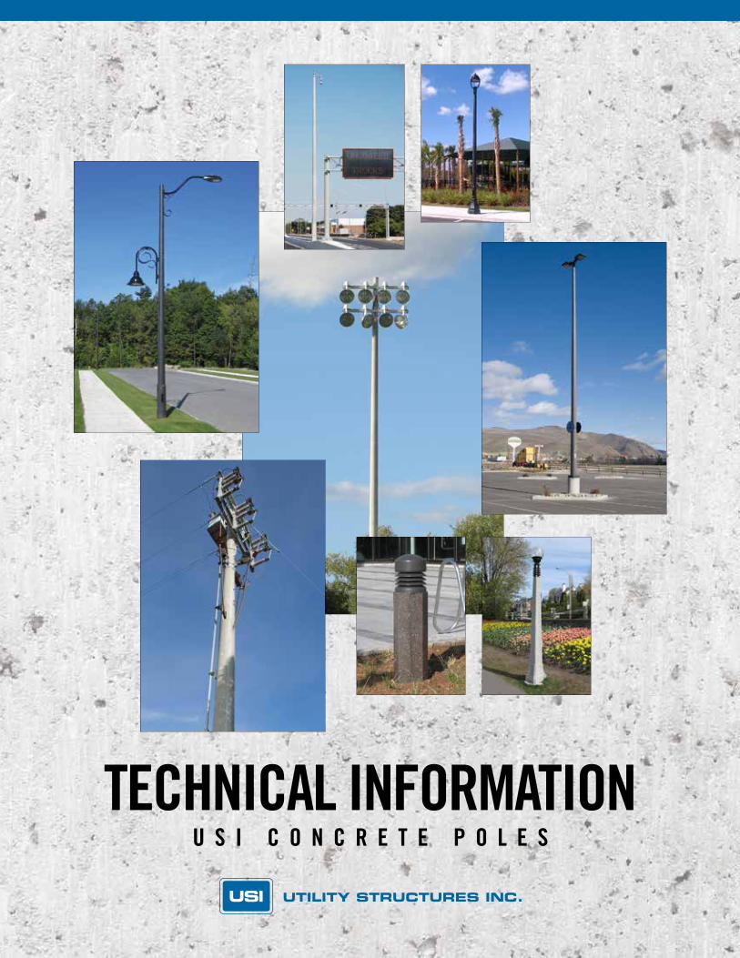
TECHNICAL INFORMATION USI CONCRETE POLES
Transcript of USI CONCRETE POLES - Utility Structures · 2014-07-30 · reinforcing wire shall conform to ASTM...
TECHNICAL INFORMATIONU S I C O N C R E T E P O L E S
61 BONGARD AVENUE, OTTAWA, ONTARIO CANADA K2E 6V2TEL: [613] 225-6398 • FAX: [613] 225-1681 • TOLL FREE: 1-800-267-6466www.utilitystructures.com
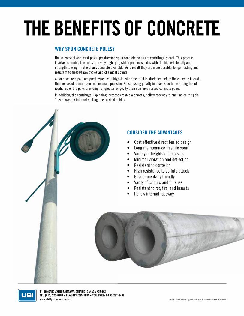
WHY SPUN CONCRETE POLES?Unlike conventional cast poles, prestressed spun concrete poles are centrifugally cast. This process involves spinning the poles at a very high rpm, which produces poles with the highest density and strength to weight ratio of any concrete available. As a result they are more durable; longer lasting and resistant to freeze/thaw cycles and chemical agents.
All our concrete pole are prestressed with high-tensile steel that is stretched before the concrete is cast, then released to maintain concrete compression. Prestressing greatly increases both the strength and resilience of the pole, providing far greater longevity than non-prestressed concrete poles.
In addition, the centrifugal (spinning) process creates a smooth, hollow raceway, tunnel inside the pole. This allows for internal routing of electrical cables.
THE BENEFITS OF CONCRETE
CONSIDER THE ADVANTAGES
• Cost effective direct buried design• Long maintenance free life span• Variety of heights and classes• Minimal vibration and deflection• Resistant to corrosion• High resistance to sulfate attack• Environmentally friendly• Varity of colours and finishes• Resistant to rot, fire, and insects• Hollow internal raceway
E.&O.E. Subject to change without notice. Printed in Canada. ©2014
61 BONGARD AVENUE, OTTAWA, ONTARIO CANADA K2E 6V2TEL: [613] 225-6398 • FAX: [613] 225-1681 • TOLL FREE: 1-800-267-6466www.utilitystructures.com
SPECIFICATIONS
MATERIALS
CementShall be high early (HE) strength and shall meet all physical requirements of CSA Standard A23.1.
Reinforcing and Stressing Strands Deformed reinforcing bars shall conform shall conform to CSA G30.12 and ASTM A615. Prestressing steel reinforcement shall conform to CSA G279 and ASTM A416. Helical reinforcing wire shall conform to ASTM A82. Galvanized or epoxy coated rebar is available upon request.
AggregatesCoarse and fine aggregates shall meet all physical requirements of CSA standard A23.1. Aggregates shall be washed to achieve optimum quality.
AdmixturesAir entrainment, water reducers, corrosion inhibitors and accelerators shall conform to CSA A23.1. Air entrainment shall be used to produce 5-8% air content in the mix, which will improve the resistance to freeze/thaw.
WaterShall be clear and free of any acid, alkali, sediment or organic matter.
HardwareAll Hardware and accessories shall be plated, hot dipped galvanized or stainless steel. Handhole frames & covers shall be manufactured using a high density zinc alloy.
All hardware such as inserts, fasteners, crossarms , pole steps ,fin caps, and base plates shall be plated, hot dipped galvanized or stainless steel.
Pole Tops All pole tops will be equipped with a weatherproof cap, except those with a tenon top or optional fin cap.
Our prestressed spun concrete poles meet design criteria of the latest revisions of CSA A14 and ASTM C1089 standards. We are also an accredited CSA A23.1 certified precast plant.
DESIGN
E.&O.E. Subject to change without notice. Printed in Canada. ©2014
61 BONGARD AVENUE, OTTAWA, ONTARIO CANADA K2E 6V2TEL: [613] 225-6398 • FAX: [613] 225-1681 • TOLL FREE: 1-800-267-6466www.utilitystructures.com
INSTALLATION
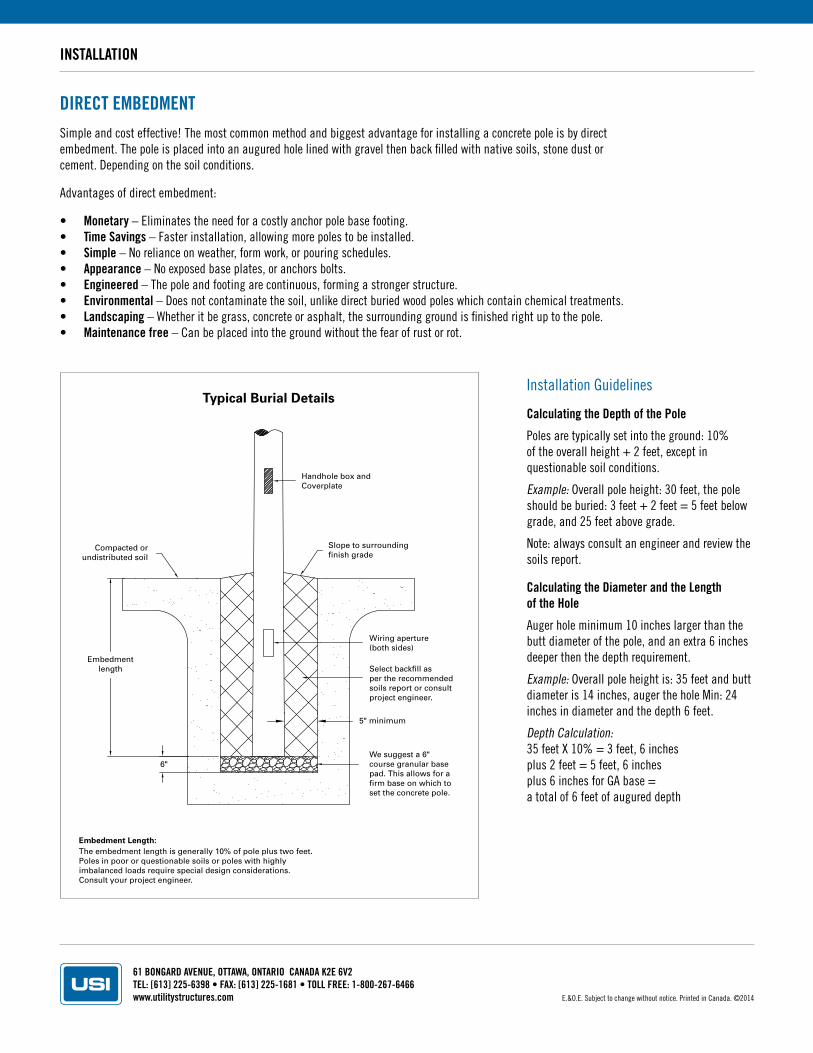
DIRECT EMBEDMENTSimple and cost effective! The most common method and biggest advantage for installing a concrete pole is by direct embedment. The pole is placed into an augured hole lined with gravel then back filled with native soils, stone dust or cement. Depending on the soil conditions.
Advantages of direct embedment:
• Monetary – Eliminates the need for a costly anchor pole base footing.• Time Savings – Faster installation, allowing more poles to be installed.• Simple – No reliance on weather, form work, or pouring schedules. • Appearance – No exposed base plates, or anchors bolts.• Engineered – The pole and footing are continuous, forming a stronger structure.• Environmental – Does not contaminate the soil, unlike direct buried wood poles which contain chemical treatments. • Landscaping – Whether it be grass, concrete or asphalt, the surrounding ground is finished right up to the pole.• Maintenance free – Can be placed into the ground without the fear of rust or rot.
Installation Guidelines
Calculating the Depth of the Pole
Poles are typically set into the ground: 10% of the overall height + 2 feet, except in questionable soil conditions.
Example: Overall pole height: 30 feet, the pole should be buried: 3 feet + 2 feet = 5 feet below grade, and 25 feet above grade.
Note: always consult an engineer and review the soils report.
Calculating the Diameter and the Length of the Hole
Auger hole minimum 10 inches larger than the butt diameter of the pole, and an extra 6 inches deeper then the depth requirement.
Example: Overall pole height is: 35 feet and butt diameter is 14 inches, auger the hole Min: 24 inches in diameter and the depth 6 feet.
Depth Calculation: 35 feet X 10% = 3 feet, 6 inches plus 2 feet = 5 feet, 6 inchesplus 6 inches for GA base = a total of 6 feet of augured depth
Compacted orundistributed soil
Embedmentlength
Handhole box andCoverplate
Slope to surroundingfinish grade
Wiring aperture(both sides)
5" minimum
6"
Select backfill as per the recommended soils report or consult project engineer.
We suggest a 6" course granular base pad. This allows for a firm base on which to set the concrete pole.
Embedment Length:The embedment length is generally 10% of pole plus two feet.Poles in poor or questionable soils or poles with highlyimbalanced loads require special design considerations.Consult your project engineer.
Typical Burial Details
E.&O.E. Subject to change without notice. Printed in Canada. ©2014
61 BONGARD AVENUE, OTTAWA, ONTARIO CANADA K2E 6V2TEL: [613] 225-6398 • FAX: [613] 225-1681 • TOLL FREE: 1-800-267-6466www.utilitystructures.com
INSTALLATION
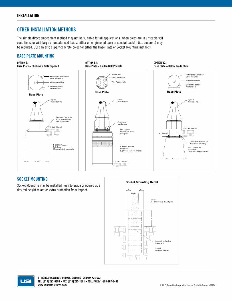
OTHER INSTALLATION METHODSThe simple direct embedment method may not be suitable for all applications. When poles are in unstable soil conditions, or with large or unbalanced loads, either an engineered base or special backfill (i.e. concrete) may be required. USI can also supply concrete poles for either the Base Plate or Socket Mounting methods.
BASE PLATE MOUNTINGOPTION B: Base Plate – Flush with Bolts Exposed
OPTION B1: Base Plate – Hidden Bolt Pockets
OPTION B2: Base Plate – Below Grade Stub
Socket Mounting may be installed flush to grade or poured at a desired height to act as extra protection from impact.
SOCKET MOUNTING
Internal reinforcing(by others)
Notes:A = 2 times butt dia. of pole
6" 6"
A
Size ofconcrete footing
Socket Mounting Detail
TypicalConcrete Pole
Typically Pole is Set2 - 3" Below Gradeto Hide Anchors
E-55 USI PrecastPole Base[Optional - Ask for details]
TYPICAL GRADE
Base Plate
Wire Access Hole
Hot Dipped GalvanizedSteel Baseplate
Slotted Holes forAnchor Bolts
Base Plate
Anchor Bolt
TypicalConcrete Pole
AluminumNut Covers
Hot DippedGalvanized SteelBaseplate
TYPICAL GRADE
E-56 USI PrecastPole Base[Optional - Ask for details]
Insert Bolt Cover
Wire Access Hole
Base Plate
TypicalConcrete Pole
Concrete Extension forBase Plate Mounting
6" [152mm]
E-52 USI PrecastPole Base[Optional - Ask for details]
Wire Access Hole
Hot Dipped GalvanizedSteel Baseplate
Slotted Holes forAnchor Bolts
TYPICAL GRADE
E.&O.E. Subject to change without notice. Printed in Canada. ©2014
61 BONGARD AVENUE, OTTAWA, ONTARIO CANADA K2E 6V2TEL: [613] 225-6398 • FAX: [613] 225-1681 • TOLL FREE: 1-800-267-6466www.utilitystructures.com
PRODUCTION
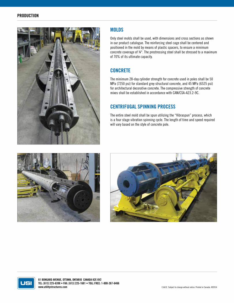
MOLDSOnly steel molds shall be used, with dimensions and cross sections as shown in our product catalogue. The reinforcing steel cage shall be centered and positioned in the mold by means of plastic spacers, to ensure a minimum concrete coverage of ¾". The prestressing steel shall be stressed to a maximum of 70% of its ultimate capacity.
CONCRETEThe minimum 28-day cylinder strength for concrete used in poles shall be 50 MPa (7250 psi) for standard grey structural concrete, and 45 MPa (6525 psi) for architectural decorative concrete. The compressive strength of concrete mixes shall be established in accordance with CAN/CSA-A23.2-9C.
CENTRIFUGAL SPINNING PROCESSThe entire steel mold shall be spun utilizing the “Vibraspun” process, which is a four stage vibration spinning cycle. The length of time and speed required will vary based on the style of concrete pole.
E.&O.E. Subject to change without notice. Printed in Canada. ©2014
61 BONGARD AVENUE, OTTAWA, ONTARIO CANADA K2E 6V2TEL: [613] 225-6398 • FAX: [613] 225-1681 • TOLL FREE: 1-800-267-6466www.utilitystructures.com
STORAGE AND HANDLING
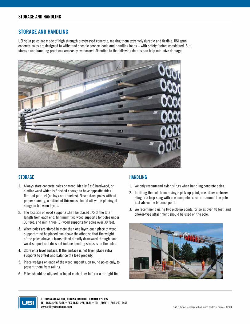
STORAGE AND HANDLINGUSI spun poles are made of high strength prestressed concrete, making them extremely durable and flexible. USI spun concrete poles are designed to withstand specific service loads and handling loads – with safety factors considered. But storage and handling practices are easily overlooked. Attention to the following details can help minimize damage.
STORAGE
1. Always store concrete poles on wood, ideally 2 x 6 hardwood, or similar wood which is finished enough to have opposite sides flat and parallel (no logs or branches). Never stack poles without proper spacing, a sufficient thickness should allow the placing of slings in between layers.
2. The location of wood supports shall be placed 1/5 of the total length from each end. Minimum two wood supports for poles under 30 feet, and min. three (3) wood supports for poles over 30 feet.
3. When poles are stored in more than one layer, each piece of wood support must be placed one above the other, so that the weight of the poles above is transmitted directly downward through each wood support and does not induce bending stresses on the poles.
4. Store on a level surface. If the surface is not level, place extra supports to offset and balance the load properly.
5. Place wedges on each of the wood supports, on round poles only, to prevent them from rolling.
6. Poles should be aligned on top of each other to form a straight line.
HANDLING
1. We only recommend nylon slings when handling concrete poles.
2. In lifting the pole from a single pick-up point, use either a choker sling or a loop sling with one complete extra turn around the pole just above the balance point.
3. We recommend using two pick-up points for poles over 40 feet, and choker-type attachment should be used on the pole.
E.&O.E. Subject to change without notice. Printed in Canada. ©2014
61 BONGARD AVENUE, OTTAWA, ONTARIO CANADA K2E 6V2TEL: [613] 225-6398 • FAX: [613] 225-1681 • TOLL FREE: 1-800-267-6466www.utilitystructures.com
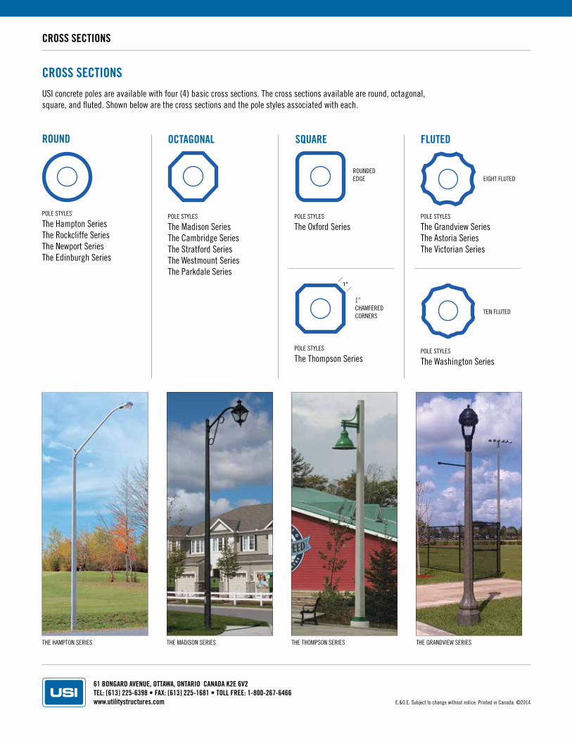
CROSS SECTIONS
ROUND
POLE STYLES
The Hampton SeriesThe Rockcliffe SeriesThe Newport SeriesThe Edinburgh Series
POLE STYLES
The Madison SeriesThe Cambridge SeriesThe Stratford SeriesThe Westmount SeriesThe Parkdale Series
POLE STYLES
The Oxford Series
POLE STYLES
The Thompson Series
POLE STYLES
The Grandview SeriesThe Astoria SeriesThe Victorian Series
POLE STYLES
The Washington Series
OCTAGONAL FLUTED
CROSS SECTIONSUSI concrete poles are available with four (4) basic cross sections. The cross sections available are round, octagonal, square, and fluted. Shown below are the cross sections and the pole styles associated with each.
SQUARE
ROUNDED EDGE EIGHT FLUTED
TEN FLUTED
1” CHAMFERED CORNERS
THE HAMPTON SERIES THE MADISON SERIES THE THOMPSON SERIES THE GRANDVIEW SERIES
E.&O.E. Subject to change without notice. Printed in Canada. ©2014
61 BONGARD AVENUE, OTTAWA, ONTARIO CANADA K2E 6V2TEL: [613] 225-6398 • FAX: [613] 225-1681 • TOLL FREE: 1-800-267-6466www.utilitystructures.com
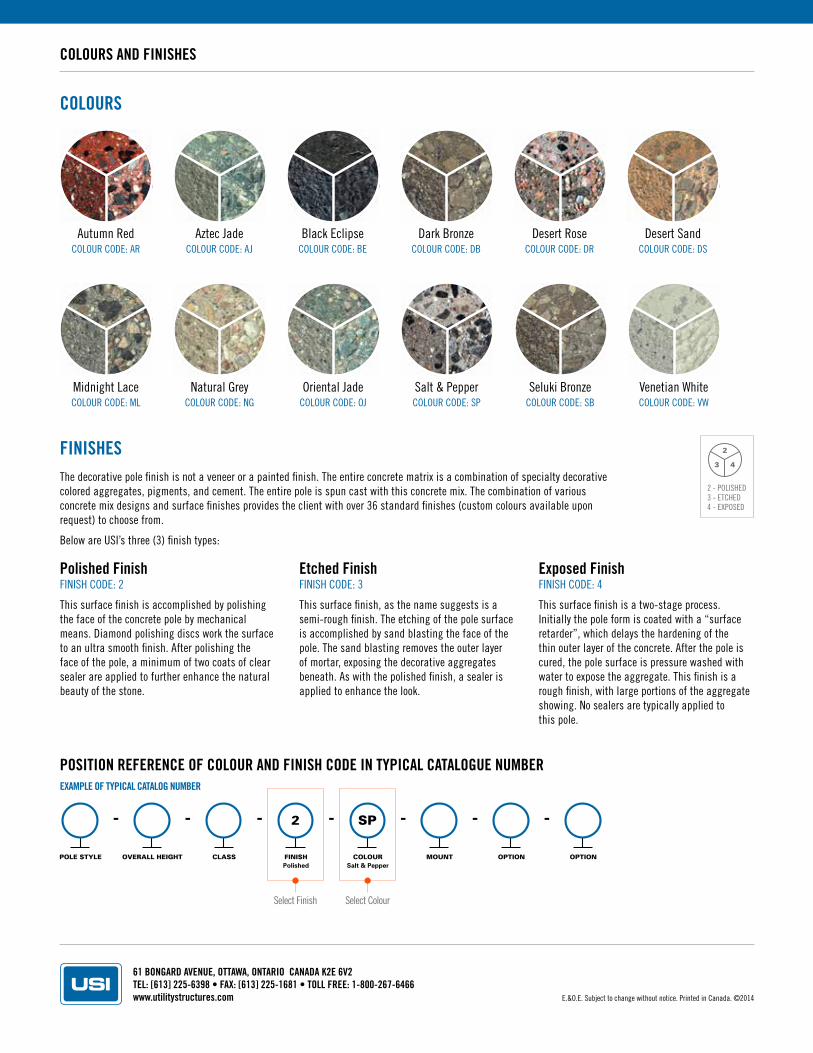
COLOURS AND FINISHES
COLOURS
FINISHESThe decorative pole finish is not a veneer or a painted finish. The entire concrete matrix is a combination of specialty decorative colored aggregates, pigments, and cement. The entire pole is spun cast with this concrete mix. The combination of various concrete mix designs and surface finishes provides the client with over 36 standard finishes (custom colours available upon request) to choose from.
Below are USI’s three (3) finish types:
Polished FinishFINISH CODE: 2
This surface finish is accomplished by polishing the face of the concrete pole by mechanical means. Diamond polishing discs work the surface to an ultra smooth finish. After polishing the face of the pole, a minimum of two coats of clear sealer are applied to further enhance the natural beauty of the stone.
Etched FinishFINISH CODE: 3
This surface finish, as the name suggests is a semi-rough finish. The etching of the pole surface is accomplished by sand blasting the face of the pole. The sand blasting removes the outer layer of mortar, exposing the decorative aggregates beneath. As with the polished finish, a sealer is applied to enhance the look.
Exposed FinishFINISH CODE: 4
This surface finish is a two-stage process. Initially the pole form is coated with a “surface retarder”, which delays the hardening of the thin outer layer of the concrete. After the pole is cured, the pole surface is pressure washed with water to expose the aggregate. This finish is a rough finish, with large portions of the aggregate showing. No sealers are typically applied to this pole.
Autumn RedCOLOUR CODE: AR
Desert RoseCOLOUR CODE: DR
Oriental JadeCOLOUR CODE: OJ
Aztec JadeCOLOUR CODE: AJ
Desert SandCOLOUR CODE: DS
Salt & PepperCOLOUR CODE: SP
Black EclipseCOLOUR CODE: BE
Midnight LaceCOLOUR CODE: ML
Seluki BronzeCOLOUR CODE: SB
Dark BronzeCOLOUR CODE: DB
Natural GreyCOLOUR CODE: NG
Venetian WhiteCOLOUR CODE: VW
2
3 4
2 - POLISHED3 - ETCHED4 - EXPOSED
POLE STYLE OVERALL HEIGHT CLASS
2
FINISHPolished
SP
COLOURSalt & Pepper
MOUNT OPTION OPTION
POSITION REFERENCE OF COLOUR AND FINISH CODE IN TYPICAL CATALOGUE NUMBEREXAMPLE OF TYPICAL CATALOG NUMBER
Select Finish Select Colour
E.&O.E. Subject to change without notice. Printed in Canada. ©2014
61 BONGARD AVENUE, OTTAWA, ONTARIO CANADA K2E 6V2TEL: [613] 225-6398 • FAX: [613] 225-1681 • TOLL FREE: 1-800-267-6466www.utilitystructures.com
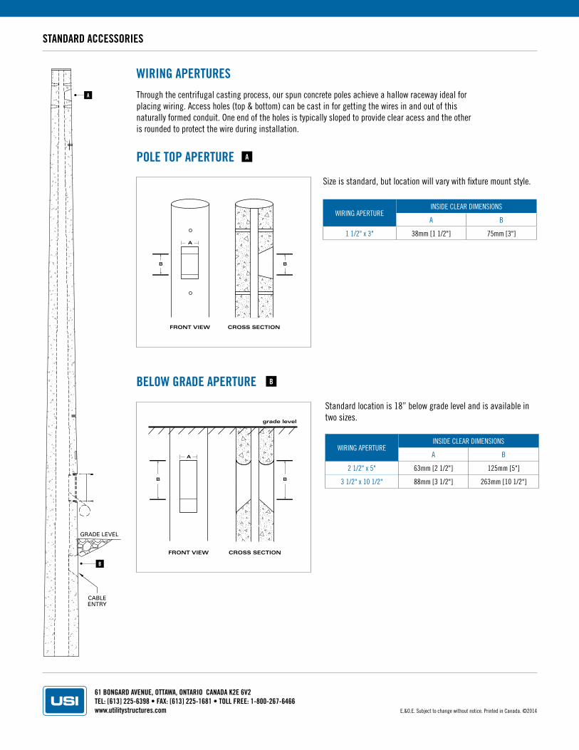
STANDARD ACCESSORIES
WIRING APERTURESThrough the centrifugal casting process, our spun concrete poles achieve a hallow raceway ideal for placing wiring. Access holes (top & bottom) can be cast in for getting the wires in and out of this naturally formed conduit. One end of the holes is typically sloped to provide clear acess and the other is rounded to protect the wire during installation.
Size is standard, but location will vary with fixture mount style.
Standard location is 18” below grade level and is available in two sizes.
POLE TOP APERTURE
BELOW GRADE APERTURE
FRONT VIEW
A
B
CROSS SECTION
B
FRONT VIEW
grade level
A
CROSS SECTION
BB
GRADE LEVEL
CABLEENTRY
A
B
WIRING APERTUREINSIDE CLEAR DIMENSIONS
A B
1 1/2" x 3" 38mm [1 1/2"] 75mm [3"]
WIRING APERTUREINSIDE CLEAR DIMENSIONS
A B
2 1/2" x 5" 63mm [2 1/2"] 125mm [5"]
3 1/2" x 10 1/2" 88mm [3 1/2"] 263mm [10 1/2"]
B
A
E.&O.E. Subject to change without notice. Printed in Canada. ©2014
61 BONGARD AVENUE, OTTAWA, ONTARIO CANADA K2E 6V2TEL: [613] 225-6398 • FAX: [613] 225-1681 • TOLL FREE: 1-800-267-6466www.utilitystructures.com
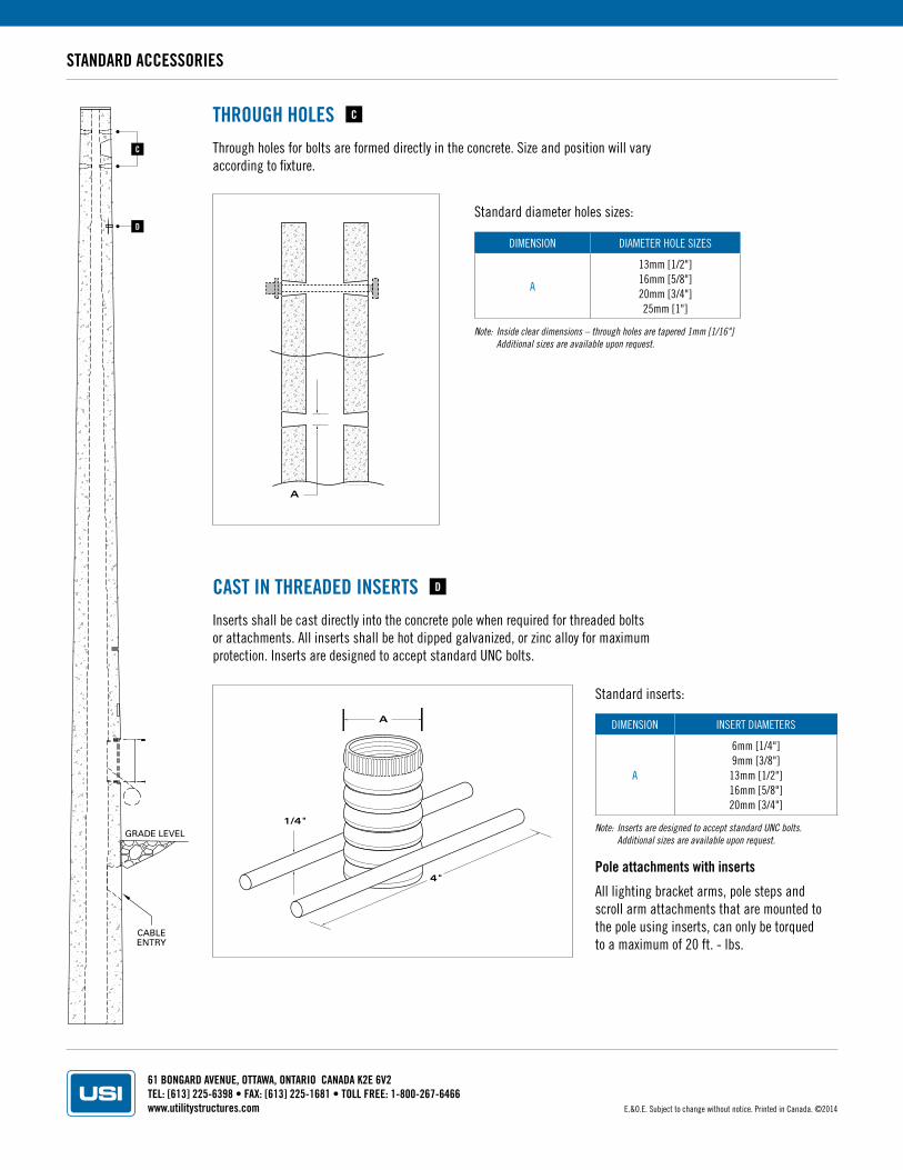
STANDARD ACCESSORIES
THROUGH HOLESThrough holes for bolts are formed directly in the concrete. Size and position will vary according to fixture.
A
DIMENSION DIAMETER HOLE SIZES
A
13mm [1/2"]16mm [5/8"]20mm [3/4"]25mm [1"]
DIMENSION INSERT DIAMETERS
A
6mm [1/4"]9mm [3/8"]
13mm [1/2"]16mm [5/8"]20mm [3/4"]
Standard diameter holes sizes:
CAST IN THREADED INSERTSInserts shall be cast directly into the concrete pole when required for threaded bolts or attachments. All inserts shall be hot dipped galvanized, or zinc alloy for maximum protection. Inserts are designed to accept standard UNC bolts.
4"
1/4"
A
GRADE LEVEL
CABLEENTRY
D
C
C
D
Note: Inside clear dimensions – through holes are tapered 1mm [1/16"] Additional sizes are available upon request.
Note: Inserts are designed to accept standard UNC bolts. Additional sizes are available upon request.
Pole attachments with inserts
All lighting bracket arms, pole steps and scroll arm attachments that are mounted to the pole using inserts, can only be torqued to a maximum of 20 ft. - lbs.
E.&O.E. Subject to change without notice. Printed in Canada. ©2014
Standard inserts:
61 BONGARD AVENUE, OTTAWA, ONTARIO CANADA K2E 6V2TEL: [613] 225-6398 • FAX: [613] 225-1681 • TOLL FREE: 1-800-267-6466www.utilitystructures.com
GRADE LEVEL
CABLEENTRY
STANDARD ACCESSORIES
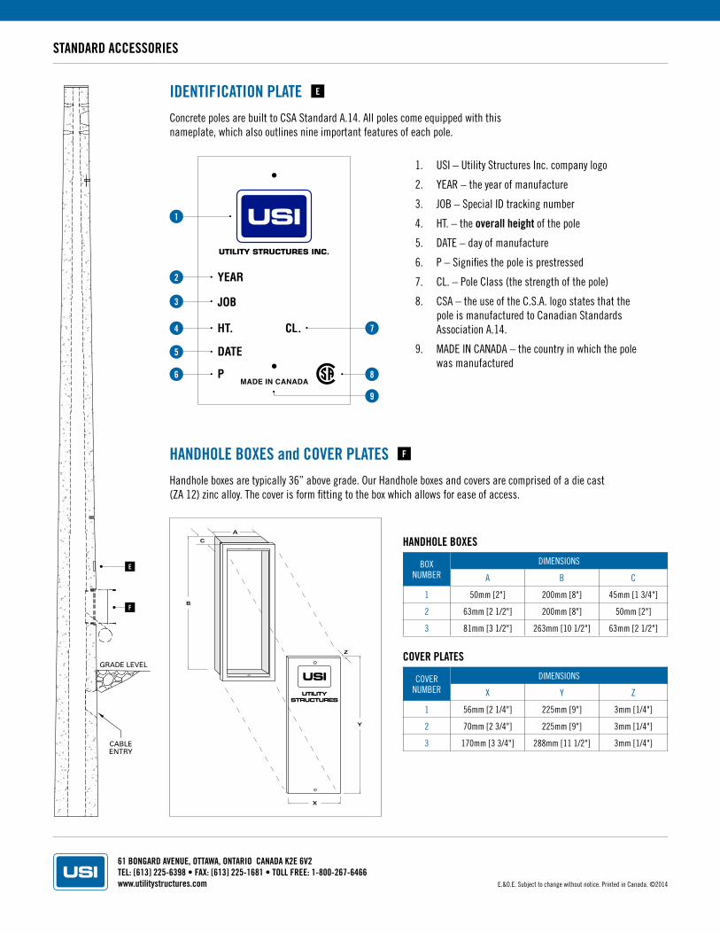
HANDHOLE BOXES and COVER PLATESHandhole boxes are typically 36” above grade. Our Handhole boxes and covers are comprised of a die cast (ZA 12) zinc alloy. The cover is form fitting to the box which allows for ease of access.
BOX NUMBER
DIMENSIONS
A B C
1 50mm [2"] 200mm [8"] 45mm [1 3/4"]
2 63mm [2 1/2"] 200mm [8"] 50mm [2"]
3 81mm [3 1/2"] 263mm [10 1/2"] 63mm [2 1/2"]
COVER NUMBER
DIMENSIONS
X Y Z
1 56mm [2 1/4"] 225mm [9"] 3mm [1/4"]
2 70mm [2 3/4"] 225mm [9"] 3mm [1/4"]
3 170mm [3 3/4"] 288mm [11 1/2"] 3mm [1/4"]
HANDHOLE BOXES
COVER PLATES
UTILITYSTRUCTURES
B
C
A
Y
X
Z
IDENTIFICATION PLATEConcrete poles are built to CSA Standard A.14. All poles come equipped with this nameplate, which also outlines nine important features of each pole.
1. USI – Utility Structures Inc. company logo
2. YEAR – the year of manufacture
3. JOB – Special ID tracking number
4. HT. – the overall height of the pole
5. DATE – day of manufacture
6. P – Signifies the pole is prestressed
7. CL. – Pole Class (the strength of the pole)
8. CSA – the use of the C.S.A. logo states that the pole is manufactured to Canadian Standards Association A.14.
9. MADE IN CANADA – the country in which the pole was manufactured
1
2
3
4
5
7
6 8
9
E
F
F
E
E.&O.E. Subject to change without notice. Printed in Canada. ©2014
61 BONGARD AVENUE, OTTAWA, ONTARIO CANADA K2E 6V2TEL: [613] 225-6398 • FAX: [613] 225-1681 • TOLL FREE: 1-800-267-6466www.utilitystructures.com
GRADE LEVEL
CABLEENTRY
STANDARD ACCESSORIES
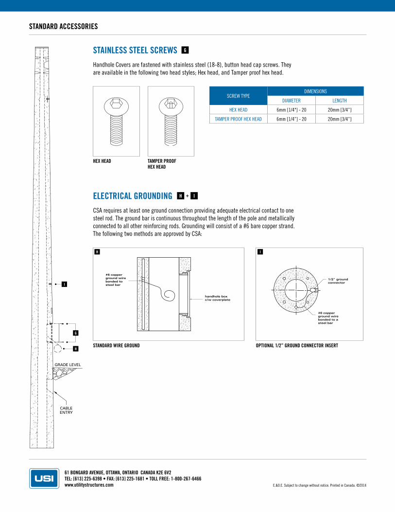
STAINLESS STEEL SCREWSHandhole Covers are fastened with stainless steel (18-8), button head cap screws. They are available in the following two head styles; Hex head, and Tamper proof hex head.
SCREW TYPEDIMENSIONS
DIAMETER LENGTH
HEX HEAD 6mm [1/4"] - 20 20mm [3/4”]
TAMPER PROOF HEX HEAD 6mm [1/4”] - 20 20mm [3/4”]
HEX HEAD TAMPER PROOFHEX HEAD
ELECTRICAL GROUNDINGCSA requires at least one ground connection providing adequate electrical contact to one steel rod. The ground bar is continuous throughout the length of the pole and metallically connected to all other reinforcing rods. Grounding will consist of a #6 bare copper strand. The following two methods are approved by CSA:
STANDARD WIRE GROUND OPTIONAL 1/2” GROUND CONNECTOR INSERT
#6 copperground wirebonded tosteel bar
handhole boxc/w coverplate
1/2" groundconnector
#6 copperground wirebonded to asteel bar
+
G
H I
G
H
H I
I
+
E.&O.E. Subject to change without notice. Printed in Canada. ©2014
61 BONGARD AVENUE, OTTAWA, ONTARIO CANADA K2E 6V2TEL: [613] 225-6398 • FAX: [613] 225-1681 • TOLL FREE: 1-800-267-6466www.utilitystructures.com
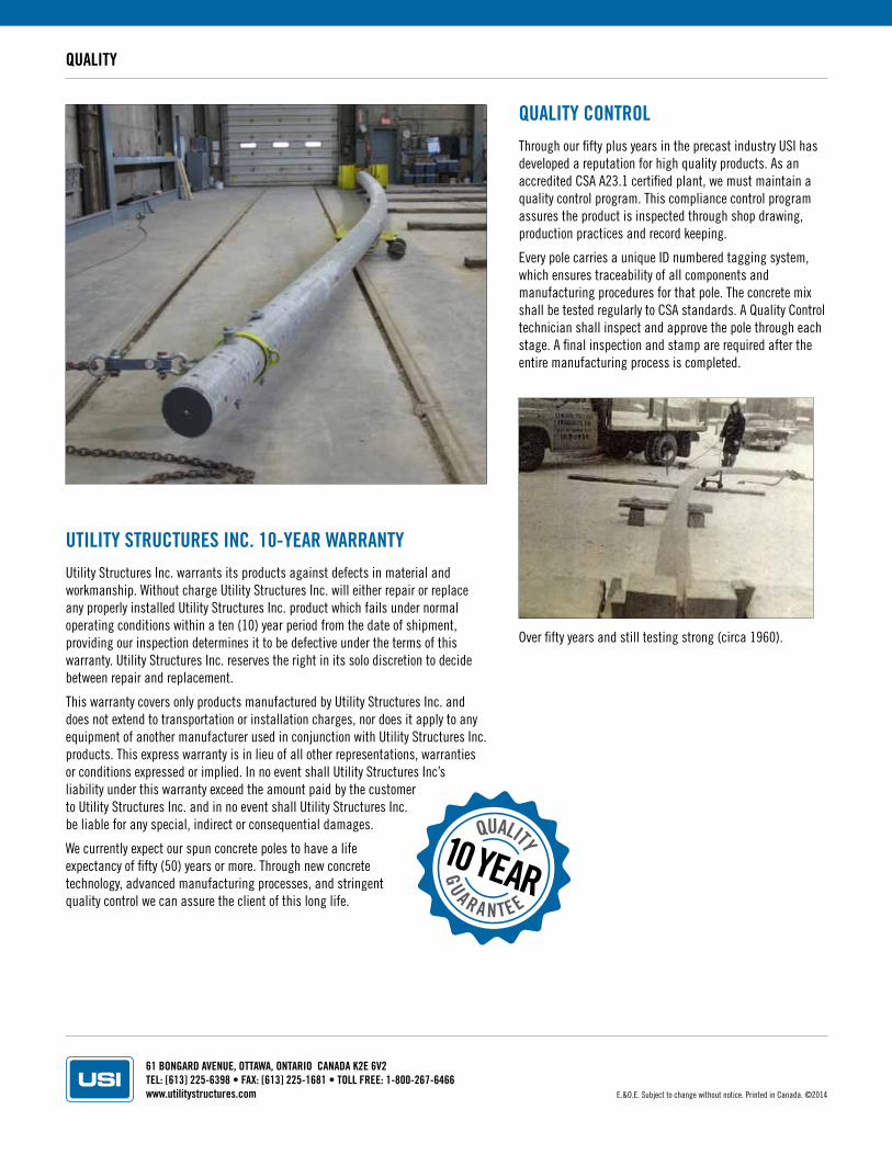
QUALITY CONTROLThrough our fifty plus years in the precast industry USI has developed a reputation for high quality products. As an accredited CSA A23.1 certified plant, we must maintain a quality control program. This compliance control program assures the product is inspected through shop drawing, production practices and record keeping.
Every pole carries a unique ID numbered tagging system, which ensures traceability of all components and manufacturing procedures for that pole. The concrete mix shall be tested regularly to CSA standards. A Quality Control technician shall inspect and approve the pole through each stage. A final inspection and stamp are required after the entire manufacturing process is completed.
QUALITY
UTILITY STRUCTURES INC. 10-YEAR WARRANTYUtility Structures Inc. warrants its products against defects in material and workmanship. Without charge Utility Structures Inc. will either repair or replace any properly installed Utility Structures Inc. product which fails under normal operating conditions within a ten (10) year period from the date of shipment, providing our inspection determines it to be defective under the terms of this warranty. Utility Structures Inc. reserves the right in its solo discretion to decide between repair and replacement.
This warranty covers only products manufactured by Utility Structures Inc. and does not extend to transportation or installation charges, nor does it apply to any equipment of another manufacturer used in conjunction with Utility Structures Inc. products. This express warranty is in lieu of all other representations, warranties or conditions expressed or implied. In no event shall Utility Structures Inc’s liability under this warranty exceed the amount paid by the customer to Utility Structures Inc. and in no event shall Utility Structures Inc. be liable for any special, indirect or consequential damages.
We currently expect our spun concrete poles to have a life expectancy of fifty (50) years or more. Through new concrete technology, advanced manufacturing processes, and stringent quality control we can assure the client of this long life.
GU A R A N TEE
QUALITY10 YEAR
Over fifty years and still testing strong (circa 1960).
E.&O.E. Subject to change without notice. Printed in Canada. ©2014