Tri Ax Carbon Test
8
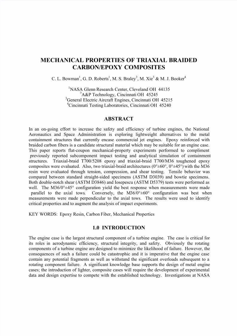
MECHANICAL PROPERTIES OF TRIAXIAL BRAIDED CARBON/EPOXY COMPOSITES C. L. Bowman 1 , G. D. Roberts 1 , M. S. Braley 2 , M. Xie 3 & M. J. Booker 4 1 NASA Glenn Research Center, Cleveland OH 44135 2 A&P Technology, Cincinnati OH 45245 3 General Electric Aircraft Engines, Cincinnati OH 45215 4 Cincinnati Testing Laboratories, Cincinnati OH 45240 ABSTRACT In an on-going effort to increase the safety and efficiency of turbine engines, the National Aeronautics and Space Administration is exploring lightweight alternatives to the metal containment structures that currently encase commercial jet engines. Epoxy reinforced with braided carbon fibers is a candidate structural material which may be suitable for an engine case. This paper reports flat-coupon mechanical-property experiments performed to compliment previously reported subcomponent impact testing and analytical simulation of containment structures. Triaxial-braid T700/5208 epoxy and t riaxial-braid T700/M36 toughened epoxy composites were evaluated. Also, two triaxial-braid architectures (0°±60°, 0°±45°) with the M36 resin were evaluated through tensi on, compression, and shear testing. Tensile behavior was compared between standard straight-sided specimens (ASTM D3039) and bowtie specimens. Both double-notch shear (ASTM D3846) and Iosepescu (ASTM D5379) tests were performed as well. The M36/0°±45° configuration yield the best response when measurements were made parallel to the axial tows . Conversely, the M36/0°±60° confi guration was best when measurements were made perpendicular to the axial tows. The results were used to identify critical properties and to augment the ana lysis of impact experiments. KEY WORDS: Epoxy Resin, Carbon Fiber, Mechanical Pr operties 1.0 INTRODUCTION The engine case is the largest structural component of a turbine engine. The case is critical for its roles in aerodynamic efficiency, structural integrity, and safety. Obviously the rotating components of a turbine engine are designed to minimize the likelihood of failure. However, the consequences of such a failure could be catastrophic and it is imperative that the engine case contain any potential fragments as well as withstand the significant overloads subsequent to a rotating component failure. A significant knowledge base supports the design of metal engine cases; the introduction of lighter, composite cases will require the development of experimental data and design expertise to compete with t he established technology. Investigations at NASA
-
Upload
matthew-michaud -
Category
Documents
-
view
221 -
download
0
Transcript of Tri Ax Carbon Test
8/6/2019 Tri Ax Carbon Test
http://slidepdf.com/reader/full/tri-ax-carbon-test 1/7
MECHANICAL PROPERTIES OF TRIAXIAL BRAIDEDCARBON/EPOXY COMPOSITES
C. L. Bowman1, G. D. Roberts
1, M. S. Braley
2, M. Xie
3& M. J. Booker
4
1 NASA Glenn Research Center, Cleveland OH 44135
2A&P Technology, Cincinnati OH 45245
3General Electric Aircraft Engines, Cincinnati OH 452154Cincinnati Testing Laboratories, Cincinnati OH 45240
ABSTRACT
In an on-going effort to increase the safety and efficiency of turbine engines, the National
Aeronautics and Space Administration is exploring lightweight alternatives to the metal
containment structures that currently encase commercial jet engines. Epoxy reinforced with braided carbon fibers is a candidate structural material which may be suitable for an engine case.
This paper reports flat-coupon mechanical-property experiments performed to compliment
previously reported subcomponent impact testing and analytical simulation of containment
structures. Triaxial-braid T700/5208 epoxy and triaxial-braid T700/M36 toughened epoxycomposites were evaluated. Also, two triaxial-braid architectures (0°±60°, 0°±45°) with the M36
resin were evaluated through tension, compression, and shear testing. Tensile behavior was
compared between standard straight-sided specimens (ASTM D3039) and bowtie specimens.Both double-notch shear (ASTM D3846) and Iosepescu (ASTM D5379) tests were performed as
well. The M36/0°±45° configuration yield the best response when measurements were made
parallel to the axial tows. Conversely, the M36/0°±60° configuration was best whenmeasurements were made perpendicular to the axial tows. The results were used to identify
critical properties and to augment the analysis of impact experiments.
KEY WORDS: Epoxy Resin, Carbon Fiber, Mechanical Properties
1.0 INTRODUCTION
The engine case is the largest structural component of a turbine engine. The case is critical for
its roles in aerodynamic efficiency, structural integrity, and safety. Obviously the rotatingcomponents of a turbine engine are designed to minimize the likelihood of failure. However, the
consequences of such a failure could be catastrophic and it is imperative that the engine case
contain any potential fragments as well as withstand the significant overloads subsequent to arotating component failure. A significant knowledge base supports the design of metal engine
cases; the introduction of lighter, composite cases will require the development of experimental
data and design expertise to compete with the established technology. Investigations at NASA
8/6/2019 Tri Ax Carbon Test
http://slidepdf.com/reader/full/tri-ax-carbon-test 2/7
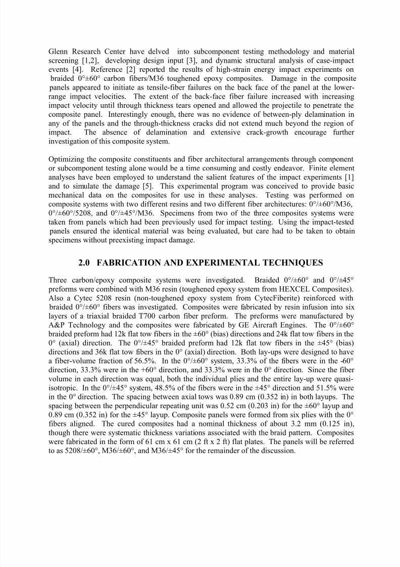
Glenn Research Center have delved into subcomponent testing methodology and material
screening [1,2], developing design input [3], and dynamic structural analysis of case-impactevents [4]. Reference [2] reported the results of high-strain energy impact experiments on
braided 0°±60° carbon fibers/M36 toughened epoxy composites. Damage in the composite
panels appeared to initiate as tensile-fiber failures on the back face of the panel at the lower-
range impact velocities. The extent of the back-face fiber failure increased with increasingimpact velocity until through thickness tears opened and allowed the projectile to penetrate the
composite panel. Interestingly enough, there was no evidence of between-ply delamination in
any of the panels and the through-thickness cracks did not extend much beyond the region of impact. The absence of delamination and extensive crack-growth encourage further
investigation of this composite system.
Optimizing the composite constituents and fiber architectural arrangements through component
or subcomponent testing alone would be a time consuming and costly endeavor. Finite element
analyses have been employed to understand the salient features of the impact experiments [1]and to simulate the damage [5]. This experimental program was conceived to provide basic
mechanical data on the composites for use in these analyses. Testing was performed oncomposite systems with two different resins and two different fiber architectures: 0°/±60°/M36,
0°/±60°/5208, and 0°/±45°/M36. Specimens from two of the three composites systems weretaken from panels which had been previously used for impact testing. Using the impact-tested
panels ensured the identical material was being evaluated, but care had to be taken to obtain
specimens without preexisting impact damage.
2.0 FABRICATION AND EXPERIMENTAL TECHNIQUES
Three carbon/epoxy composite systems were investigated. Braided 0°/±60° and 0°/±45°
preforms were combined with M36 resin (toughened epoxy system from HEXCEL Composites).
Also a Cytec 5208 resin (non-toughened epoxy system from CytecFiberite) reinforced with braided 0°/±60° fibers was investigated. Composites were fabricated by resin infusion into six
layers of a triaxial braided T700 carbon fiber preform. The preforms were manufactured by
A&P Technology and the composites were fabricated by GE Aircraft Engines. The 0°/±60° braided preform had 12k flat tow fibers in the ±60° (bias) directions and 24k flat tow fibers in the
0° (axial) direction. The 0°/±45° braided preform had 12k flat tow fibers in the ±45° (bias)
directions and 36k flat tow fibers in the 0° (axial) direction. Both lay-ups were designed to havea fiber-volume fraction of 56.5%. In the 0°/±60° system, 33.3% of the fibers were in the -60°
direction, 33.3% were in the +60° direction, and 33.3% were in the 0° direction. Since the fiber
volume in each direction was equal, both the individual plies and the entire lay-up were quasi-
isotropic. In the 0°/±45° system, 48.5% of the fibers were in the ±45° direction and 51.5% were
in the 0° direction. The spacing between axial tows was 0.89 cm (0.352 in) in both layups. Thespacing between the perpendicular repeating unit was 0.52 cm (0.203 in) for the ±60° layup and
0.89 cm (0.352 in) for the ±45° layup. Composite panels were formed from six plies with the 0°fibers aligned. The cured composites had a nominal thickness of about 3.2 mm (0.125 in),
though there were systematic thickness variations associated with the braid pattern. Composites
were fabricated in the form of 61 cm x 61 cm (2 ft x 2 ft) flat plates. The panels will be referredto as 5208/±60°, M36/±60°, and M36/±45° for the remainder of the discussion.
8/6/2019 Tri Ax Carbon Test
http://slidepdf.com/reader/full/tri-ax-carbon-test 3/7
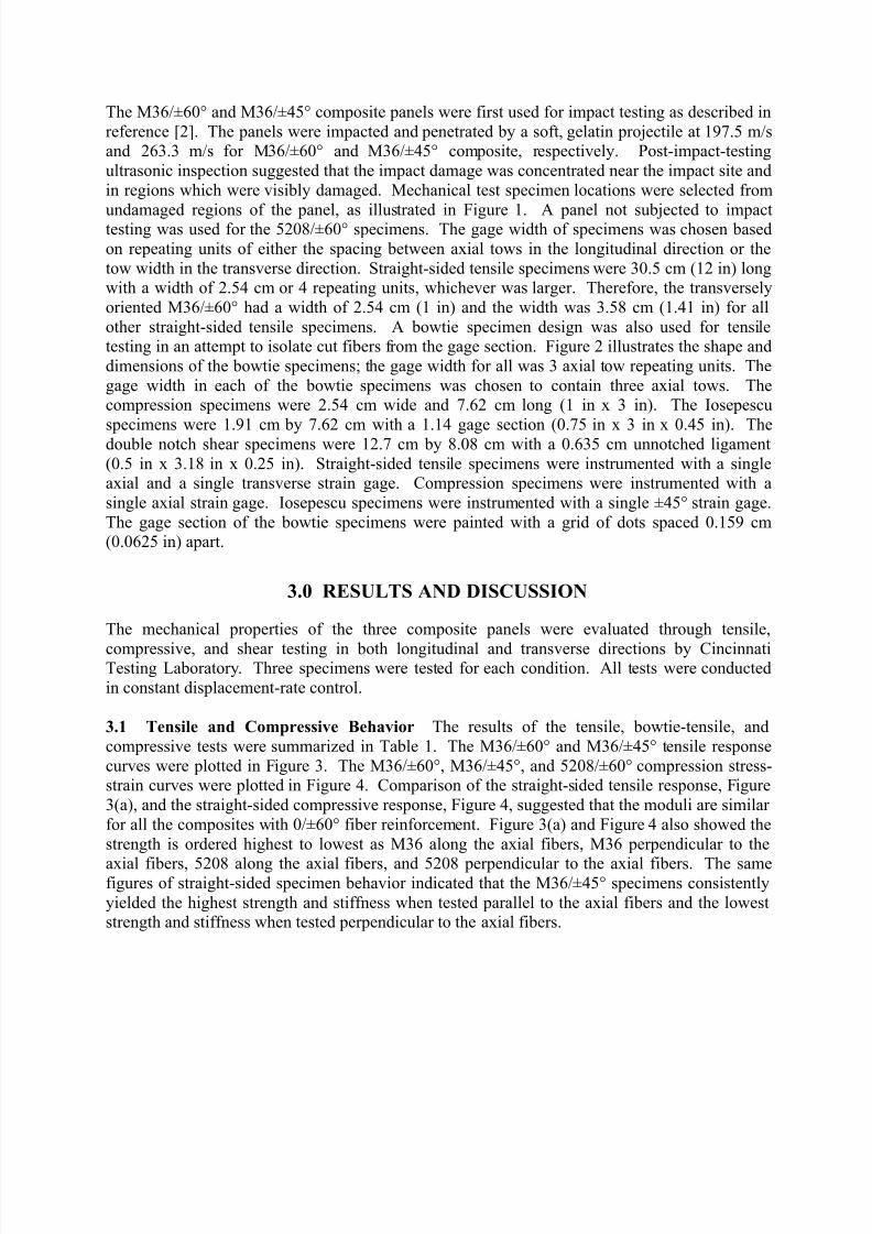
The M36/±60° and M36/±45° composite panels were first used for impact testing as described in
reference [2]. The panels were impacted and penetrated by a soft, gelatin projectile at 197.5 m/sand 263.3 m/s for M36/±60° and M36/±45° composite, respectively. Post-impact-testing
ultrasonic inspection suggested that the impact damage was concentrated near the impact site and
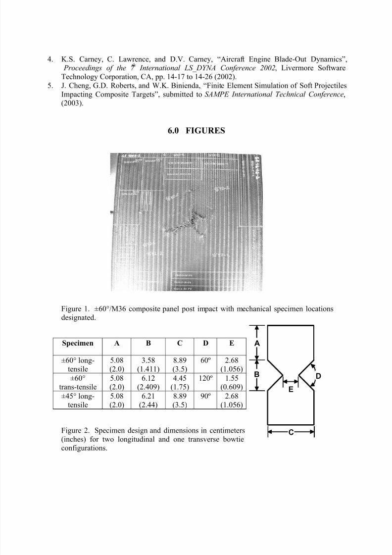
in regions which were visibly damaged. Mechanical test specimen locations were selected from
undamaged regions of the panel, as illustrated in Figure 1. A panel not subjected to impacttesting was used for the 5208/±60° specimens. The gage width of specimens was chosen based
on repeating units of either the spacing between axial tows in the longitudinal direction or the
tow width in the transverse direction. Straight-sided tensile specimens were 30.5 cm (12 in) longwith a width of 2.54 cm or 4 repeating units, whichever was larger. Therefore, the transversely
oriented M36/±60° had a width of 2.54 cm (1 in) and the width was 3.58 cm (1.41 in) for all
other straight-sided tensile specimens. A bowtie specimen design was also used for tensiletesting in an attempt to isolate cut fibers from the gage section. Figure 2 illustrates the shape and
dimensions of the bowtie specimens; the gage width for all was 3 axial tow repeating units. The
gage width in each of the bowtie specimens was chosen to contain three axial tows. Thecompression specimens were 2.54 cm wide and 7.62 cm long (1 in x 3 in). The Iosepescu
specimens were 1.91 cm by 7.62 cm with a 1.14 gage section (0.75 in x 3 in x 0.45 in). Thedouble notch shear specimens were 12.7 cm by 8.08 cm with a 0.635 cm unnotched ligament
(0.5 in x 3.18 in x 0.25 in). Straight-sided tensile specimens were instrumented with a singleaxial and a single transverse strain gage. Compression specimens were instrumented with a
single axial strain gage. Iosepescu specimens were instrumented with a single ±45° strain gage.
The gage section of the bowtie specimens were painted with a grid of dots spaced 0.159 cm(0.0625 in) apart.
3.0 RESULTS AND DISCUSSION
The mechanical properties of the three composite panels were evaluated through tensile,
compressive, and shear testing in both longitudinal and transverse directions by CincinnatiTesting Laboratory. Three specimens were tested for each condition. All tests were conducted
in constant displacement-rate control.
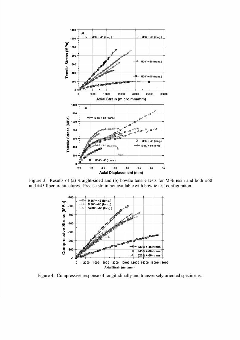
3.1 Tensile and Compressive Behavior The results of the tensile, bowtie-tensile, and
compressive tests were summarized in Table 1. The M36/±60° and M36/±45° tensile response
curves were plotted in Figure 3. The M36/±60°, M36/±45°, and 5208/±60° compression stress-strain curves were plotted in Figure 4. Comparison of the straight-sided tensile response, Figure
3(a), and the straight-sided compressive response, Figure 4, suggested that the moduli are similar
for all the composites with 0/±60° fiber reinforcement. Figure 3(a) and Figure 4 also showed the
strength is ordered highest to lowest as M36 along the axial fibers, M36 perpendicular to the
axial fibers, 5208 along the axial fibers, and 5208 perpendicular to the axial fibers. The samefigures of straight-sided specimen behavior indicated that the M36/±45° specimens consistently
yielded the highest strength and stiffness when tested parallel to the axial fibers and the loweststrength and stiffness when tested perpendicular to the axial fibers.
8/6/2019 Tri Ax Carbon Test
http://slidepdf.com/reader/full/tri-ax-carbon-test 4/7
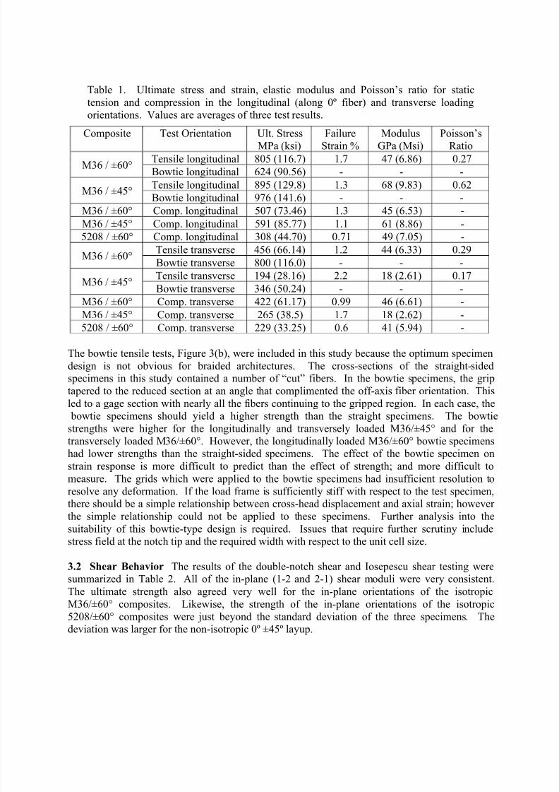
Table 1. Ultimate stress and strain, elastic modulus and Poisson’s ratio for static
tension and compression in the longitudinal (along 0º fiber) and transverse loadingorientations. Values are averages of three test results.
Composite Test Orientation Ult. StressMPa (ksi) FailureStrain % ModulusGPa (Msi) Poisson’sRatio
Tensile longitudinal 805 (116.7) 1.7 47 (6.86) 0.27M36 / ±60°
Bowtie longitudinal 624 (90.56) - - -
Tensile longitudinal 895 (129.8) 1.3 68 (9.83) 0.62M36 / ±45°
Bowtie longitudinal 976 (141.6) - - -
M36 / ±60° Comp. longitudinal 507 (73.46) 1.3 45 (6.53) -
M36 / ±45° Comp. longitudinal 591 (85.77) 1.1 61 (8.86) -
5208 / ±60° Comp. longitudinal 308 (44.70) 0.71 49 (7.05) -
Tensile transverse 456 (66.14) 1.2 44 (6.33) 0.29M36 / ±60°
Bowtie transverse 800 (116.0) - - -
Tensile transverse 194 (28.16) 2.2 18 (2.61) 0.17M36 / ±45°Bowtie transverse 346 (50.24) - - -
M36 / ±60° Comp. transverse 422 (61.17) 0.99 46 (6.61) -
M36 / ±45° Comp. transverse 265 (38.5) 1.7 18 (2.62) -
5208 / ±60° Comp. transverse 229 (33.25) 0.6 41 (5.94) -
The bowtie tensile tests, Figure 3(b), were included in this study because the optimum specimen
design is not obvious for braided architectures. The cross-sections of the straight-sidedspecimens in this study contained a number of “cut” fibers. In the bowtie specimens, the grip
tapered to the reduced section at an angle that complimented the off-axis fiber orientation. This
led to a gage section with nearly all the fibers continuing to the gripped region. In each case, the
bowtie specimens should yield a higher strength than the straight specimens. The bowtiestrengths were higher for the longitudinally and transversely loaded M36/±45° and for the
transversely loaded M36/±60°. However, the longitudinally loaded M36/±60° bowtie specimenshad lower strengths than the straight-sided specimens. The effect of the bowtie specimen on
strain response is more difficult to predict than the effect of strength; and more difficult to
measure. The grids which were applied to the bowtie specimens had insufficient resolution to
resolve any deformation. If the load frame is sufficiently stiff with respect to the test specimen,there should be a simple relationship between cross-head displacement and axial strain; however
the simple relationship could not be applied to these specimens. Further analysis into the
suitability of this bowtie-type design is required. Issues that require further scrutiny includestress field at the notch tip and the required width with respect to the unit cell size.
3.2 Shear Behavior The results of the double-notch shear and Iosepescu shear testing weresummarized in Table 2. All of the in-plane (1-2 and 2-1) shear moduli were very consistent.
The ultimate strength also agreed very well for the in-plane orientations of the isotropic
M36/±60° composites. Likewise, the strength of the in-plane orientations of the isotropic
5208/±60° composites were just beyond the standard deviation of the three specimens. Thedeviation was larger for the non-isotropic 0º ±45º layup.
8/6/2019 Tri Ax Carbon Test
http://slidepdf.com/reader/full/tri-ax-carbon-test 5/7
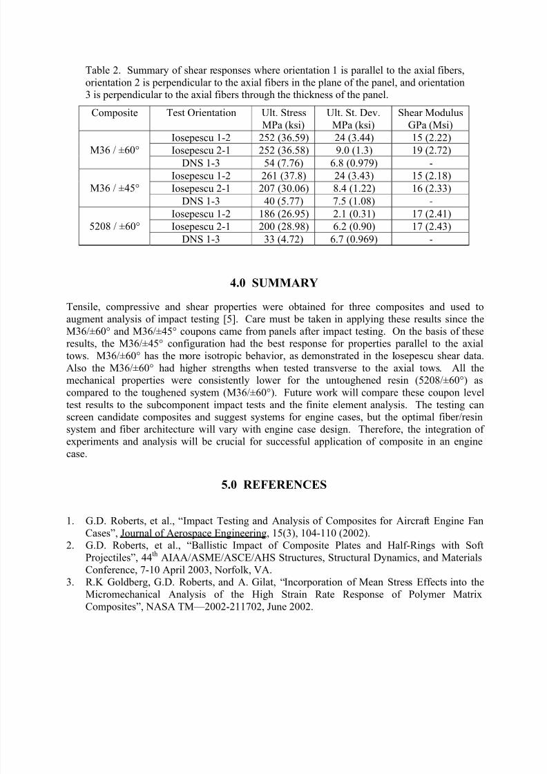
Table 2. Summary of shear responses where orientation 1 is parallel to the axial fibers,
orientation 2 is perpendicular to the axial fibers in the plane of the panel, and orientation3 is perpendicular to the axial fibers through the thickness of the panel.
Composite Test Orientation Ult. Stress
MPa (ksi)
Ult. St. Dev.
MPa (ksi)
Shear Modulus
GPa (Msi)
Iosepescu 1-2 252 (36.59) 24 (3.44) 15 (2.22)Iosepescu 2-1 252 (36.58) 9.0 (1.3) 19 (2.72)M36 / ±60°
DNS 1-3 54 (7.76) 6.8 (0.979) -
Iosepescu 1-2 261 (37.8) 24 (3.43) 15 (2.18)
Iosepescu 2-1 207 (30.06) 8.4 (1.22) 16 (2.33)M36 / ±45°
DNS 1-3 40 (5.77) 7.5 (1.08) -
Iosepescu 1-2 186 (26.95) 2.1 (0.31) 17 (2.41)
Iosepescu 2-1 200 (28.98) 6.2 (0.90) 17 (2.43)5208 / ±60°
DNS 1-3 33 (4.72) 6.7 (0.969) -
4.0 SUMMARY
Tensile, compressive and shear properties were obtained for three composites and used to
augment analysis of impact testing [5]. Care must be taken in applying these results since the
M36/±60° and M36/±45° coupons came from panels after impact testing. On the basis of theseresults, the M36/±45° configuration had the best response for properties parallel to the axial
tows. M36/±60° has the more isotropic behavior, as demonstrated in the Iosepescu shear data.
Also the M36/±60° had higher strengths when tested transverse to the axial tows. All themechanical properties were consistently lower for the untoughened resin (5208/±60°) as
compared to the toughened system (M36/±60°). Future work will compare these coupon level
test results to the subcomponent impact tests and the finite element analysis. The testing canscreen candidate composites and suggest systems for engine cases, but the optimal fiber/resin
system and fiber architecture will vary with engine case design. Therefore, the integration of experiments and analysis will be crucial for successful application of composite in an engine
case.
5.0 REFERENCES
1. G.D. Roberts, et al., “Impact Testing and Analysis of Composites for Aircraft Engine Fan
Cases”, Journal of Aerospace Engineering, 15(3), 104-110 (2002).
2. G.D. Roberts, et al., “Ballistic Impact of Composite Plates and Half-Rings with SoftProjectiles”, 44
thAIAA/ASME/ASCE/AHS Structures, Structural Dynamics, and Materials
Conference, 7-10 April 2003, Norfolk, VA.3. R.K Goldberg, G.D. Roberts, and A. Gilat, “Incorporation of Mean Stress Effects into the
Micromechanical Analysis of the High Strain Rate Response of Polymer Matrix
Composites”, NASA TM—2002-211702, June 2002.
8/6/2019 Tri Ax Carbon Test
http://slidepdf.com/reader/full/tri-ax-carbon-test 6/7
4. K.S. Carney, C. Lawrence, and D.V. Carney, “Aircraft Engine Blade-Out Dynamics”, Proceedings of the 7
thInternational LS_DYNA Conference 2002, Livermore Software
Technology Corporation, CA, pp. 14-17 to 14-26 (2002).
5. J. Cheng, G.D. Roberts, and W.K. Binienda, “Finite Element Simulation of Soft Projectiles
Impacting Composite Targets”, submitted to SAMPE International Technical Conference,(2003).
6.0 FIGURES
Figure 1. ±60°/M36 composite panel post impact with mechanical specimen locationsdesignated.
Specimen A B C D E
±60° long-tensile
5.08(2.0)
3.58(1.411)
8.89(3.5)
60º 2.68(1.056)
±60°
trans-tensile
5.08
(2.0)
6.12
(2.409)
4.45
(1.75)
120º 1.55
(0.609)±45° long-
tensile5.08(2.0)
6.21(2.44)
8.89(3.5)
90º 2.68(1.056)
Figure 2. Specimen design and dimensions in centimeters
(inches) for two longitudinal and one transverse bowtieconfigurations.
C
B D
A
E
C
B D
A
E
8/6/2019 Tri Ax Carbon Test
http://slidepdf.com/reader/full/tri-ax-carbon-test 7/7
Figure 3. Results of (a) straight-sided and (b) bowtie tensile tests for M36 resin and both ±60and ±45 fiber architectures. Precise strain not available with bowtie test configuration.
Figure 4. Compressive response of longitudinally and transversely oriented specimens.
Axial Strain (micro mm/mm)
0 5000 10000 15000 20000 25000 30000
T e n s i l e S t r e s s ( M P a )
0
200
400
600
800
1000
1200
1400
M36/ +-60 (trans.)
M36/ +-60 (long.)M36/ +-45 (long.)
M36/ +-45 (trans.)
(a)
Axial Displacement (mm)
0.0 1.0 2.0 3.0 4.0 5.0 6.0 7.0
T e n s i l e S t r e s s ( M P a
)
0
200
400
600
800
1000
1200
1400
M36/ +-60 (long.)
M36/ +-45 (long.)
M36/ +-45 (trans.)
M36/ +-60 (trans.)
(b)
Axial Strain (mm/mm)
-0 -2000 -4000 -6000 -8000 -10000-12000-14000-16000-18000
C o m p r e s
s i v e S t r e s s ( M P a )
-0
-100
-200
-300
-400
-500
-600
-700M36/ +-45 (long.)
M36/ +-60 (long.)
5208/ +-60 (long.)
M36/ +-45 (trans.)
M36/ +-60 (trans.)
5208/ +-60 (trans.)