Stormdoor Install 6ddaef76 8e17 441b 99f7 275ceb2bc2a4
11
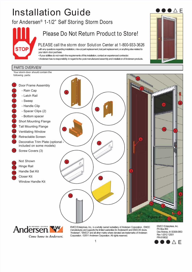
1 Y our storm door should contain the following parts: for Andersen ® 1-1/2” Self Storing Storm Doors Installati on Guide Please Do Not Return Produ ct t o Stor e! EMCO Enterprises, Inc. PO Box 853 Des Moines, IA 50306-0853 Rev 1-2012 12001 P/N 618832 with any questions regarding installation, mis-cut part replacement, lost part replacement, or anything else related to your storm door purchase. • If your abilities do not match the requirements of this installation, contact an experienced contractor. • Andersen has no respons ibil ity in regard to the post-ma nufactured assem bly and i nstallati on of Andersen produ cts. PLEASE call th e sto rm door Soluti on Center at 1-800-933-3626 EMC O Enterpri ses, Inc., i s a wholly owned subsidiary of A ndersen Corporation. EMC O manufactures and supports the limited warranties for Andersen® and EMCO® doors. “Andersen”, “EMCO” and all other marks where denoted are trademarks of Andersen Corporation. ©20 11 And ersen C orporation. All rights reserved. PARTS OVERVIEW Door Frame Assembly - Rain Cap - Latch Rail - Sweep - Handle Clip - Spacer Clips (2) - Bottom spacer Short Mounting Flange Tall Mounting Flange Ventilating Window Retractable Screen Decorative Trim Plate (optional - included on some models) Screw Covers (3) Not Shown Hinge Rail Handle Set Kit Closer Kit Window Handle Kit 2 15 14 13 9 10 3 11 12 4 5 6 7 8 1 12 13 1 2 8 10 10 3 7 6 6 12 11 16 17 8 9 5 6 7 Figure 1 4 5 E E
Transcript of Stormdoor Install 6ddaef76 8e17 441b 99f7 275ceb2bc2a4
7/24/2019 Stormdoor Install 6ddaef76 8e17 441b 99f7 275ceb2bc2a4
http://slidepdf.com/reader/full/stormdoor-install-6ddaef76-8e17-441b-99f7-275ceb2bc2a4 1/111
Your storm door should contain the
following parts:
for Andersen® 1-1/2” Self Storing Storm Doors
Installation Guide
Please Do Not Return Product to Store!
EMCO Enterprises, Inc.PO Box 853Des Moines, IA 50306-08Rev 1-2012 12001
P/N 618832
with any questions regarding installation, mis-cut part replacement, lost part replacement, or anything else related to
your storm door purchase.
• If your abilities do not match the requirements of this installation, contact an experienced contractor.
• Andersen has no responsibility in regard to the post-manufactured assembly and installation of Andersen products.
PLEASE call the storm door Solution Center at 1-800-933-3626
EMCO Enterprises, Inc., is a wholly owned subsidiary of Andersen Corporation. EMCOmanufactures and supports the limited warranties for Andersen® and EMCO® doors.“Andersen”, “EMCO” and all other marks where denoted are trademarks of AndersenCorporation. ©2011 Andersen Corporation. All rights reserved.
PARTS OVERVIEW
Door Frame Assembly
- Rain Cap
- Latch Rail
- Sweep
- Handle Clip
- Spacer Clips (2)
- Bottom spacer
Short Mounting Flange
Tall Mounting Flange
Ventilating Window
Retractable Screen
Decorative Trim Plate (optional -included on some models)
Screw Covers (3)
Not Shown
Hinge Rail
Handle Set Kit
Closer Kit
Window Handle Kit
2
15
14
13
9
10
3
11
12
4
5
6
7
8
1
12
13
1
2
8
10
10
3
7
12
11
16
17
8
9
5
6
7
Figure 1
4
5
E

7/24/2019 Stormdoor Install 6ddaef76 8e17 441b 99f7 275ceb2bc2a4
http://slidepdf.com/reader/full/stormdoor-install-6ddaef76-8e17-441b-99f7-275ceb2bc2a4 2/112
Improper use of handor power tools couldresult in injury and/orproduct damage.Follow equipmentmanufacturer’sinstructions for safeoperation. Alwayswear safety glasses.
Windows and doorscan be heavy. Use safelifting techniques anda reasonable numberof people with enoughstrength to lift, carry, andinstall window and doorproducts to avoid injuryand/or property damage.
The insect screen isintended for reasonableinsect control and not theretention of objects orpersons within the interior.The insect screen materialwill not stop a person fromfalling through the door.
Metal fasteners and other hardware components maycorrode when exposed to preservative treated andfire-retardant treated lumber. Obtain and use theappropriate size stainless steel fasteners and hardwareas called out by the installation guide to fasten unitto any rough opening made from pressure treatedand fire-retardant treated lumber. Failure to use theappropriate materials for the installation may cause afailure resulting in injury, property or product damage.
Entry doorhardwareand handlemaybecomehot whenexposed tosunlight.
WARNING WARNING WARNING WARNING WARNING
1. VERIFY MOUNTING REQUIREMENTS
RECOMMENDED TOOLS
• Drill• Tape Measure
• Screwdrivers• Safety Glasses
H
W1
W2
W3
1”
2 1/2”
3/4”
Figure 3
Figure 2
38 5/8”
TO TOP OF DOOR
2 1/2”
Figure 4
To install the storm door, you must verify that there is the necessary opening width and height and asuf ficient mounting surface.
Measure the width at the top, middle, and bottom of the opening (Figure 2). Measure from the
inside of the brick mold or exterior trim.
Measure the height at the center of the opening. Measure from the inside of the brick mold or
exterior trim, down to the top of the bottom sill.
Make sure that the brick mold or exterior trim meets the mounting surface requirements to install
the rain cap, hinge rail and latch rail (Figure 3). You must have a minimum of:
If your opening does not meet the 1” mounting surface depth (ie: flat casing or 1x4 trim), you will
need to attach shims to the face of your trim to create the required 1” depth. A recommendedsolution is to purchase insect screen molding and attach to your trim with 3/4” brad nails.
If entry door sill is bent or damaged, product may not install correctly. Replace bent or damaged
entry door sill prior to storm door installation
Most homeowners prefer to have the storm door handle on the same side as the entry door
handle. In shallow door openings, this can cause the two handles to interfere. Check for
potential interference using the rough measurements (Figure 4). If you anticipate that there will
be interference, purchase a storm door that is hinged on the opposite side of you entry door.
1.
2.
3.
4.
5.
6.
1” mounting surface depth.
3/4” mounting surface front.
2 1/2” space between the existing door and the mounting
surface for the handle set installation.
•••
Use the this table
to determine if your
storm door will fit into
the opening:
Nominal Storm Opening Sizes
Door Sizes W 1 - 3 (width) H (height)
36” x 80” 35 7/8” TO 36 3/8”
34” x 80” 33 7/8” TO 34 3/8” 80” TO 80 7/8”
32” x 80” 31 7/8” TO 32 3/8”
*
*
For opening widths up to 1” wider or for mounting surface depth between 5/8” - 3/4”, please
call our Solution Center at 1-800-933-3626 to purchase a special kit to accommodate your
situation.
SAFETY FIRST - PLEASE READ AND FOLLOW ALL WARNINGS AND CAUTIONS IN THIS GUIDE.
7/24/2019 Stormdoor Install 6ddaef76 8e17 441b 99f7 275ceb2bc2a4
http://slidepdf.com/reader/full/stormdoor-install-6ddaef76-8e17-441b-99f7-275ceb2bc2a4 3/113
2. INSTALLATION PREPARATION:
In this step, you will confirm your storm door hinges on the
correct side.
Confirm your storm door hinges correctly by using your
measurements from step 1 and comparing your door to
figures 5 and 6.
Position the door on a protected surface so the exterior side
of the door is facing up.
TIP: Lay on door carton
Starting at the mitered corners, remove clear protective tape
from bottom of door, and the bottom 3” of the door sides.Place decorative trim plate onto the door and align edge
of decorative trim plate with latch side edge of door frame.
(Figure 7)
Fasten decorative trim plate to door frame using three #8 x
1/2” self drilling screws. (included in closer kit)
Remove door from carton, grasping the door as shown
NOTE: when lifting the door, support the weight of the door
by the door frame, not the hinge and latch rails.
With door standing, ensure latch rail is properly seated in
the orange spacer clips (Figure 8B), and ensure bottom
spacer is attached to the bottom of the door and is slid to
the handle side. (Figure 8A)
NOTE: See troubleshooting section at the end of the install
guide if bottom spacer becomes detached from the door
frame.
1.
2.
3.
4.
5.
6.
7.
RIGHT HANDEDLEFT HANDED
EXTERIORVIEWSFigure 5 Figure 6
Tools needed: 3 - #8x1/2”
If your door came with a decorative trim plate, you will attach it
to the exterior of your door in this step.
NOTE: Some models include an optional decorative trim plate
for the bottom exterior of the door. If your door includes this
decorative trim plate and you wish to attach it, complete steps
2-5 below. If not, skip to step 6.
In this step, you will ensure all clips are properly attached to the
door and mounting componets
Figure 8
Figure 8B
Figure 8A
Grasp Here
Figure 7
12
1
7/24/2019 Stormdoor Install 6ddaef76 8e17 441b 99f7 275ceb2bc2a4
http://slidepdf.com/reader/full/stormdoor-install-6ddaef76-8e17-441b-99f7-275ceb2bc2a4 4/114
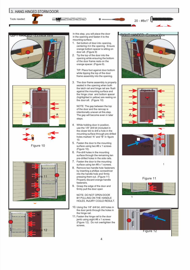
RIGHT HANDED - EXTERIOR VIEW LEFT HANDED - EXTERIOR VIEW
3. HANG HINGED STORM DOOR
Tools needed:
In this step, you will place the door
in the opening and fasten it to the
mounting surface.
Set bottom of door into opening,
centering it in the opening. Ensureorange bottom spacer is sitting on
door sill. (Figure 9)
Tip the top of the door into the
opening while ensuring the bottom
of the door frame rests on the
orange spacer. (Figure 9).
TIP: Place foot against door bottom
while tipping the top of the door
frame assembly into the opening.
The door frame assembly is properly
seated in the opening when both
the latch rail and hinge rail are flush
against the mounting surface and
the hinge z-bar and bottom spacer(highlighted in yellow) are resting on
the door sill. (Figure 10)
NOTE: The gap between the top
of the door and the raincap is
intentionally uneven at this step.
The gap will become even in later
steps.
While holding door in position,
use the 1/8” drill bit (included in
the closer kit) to drill a hole in the
mounting surface through pre-drilled
holes marked “A” and “B” in figure
10.
Fasten the door to the mounting
surface using two #8 x 1 screws
(Figure 10).
Pre-drill holes in the mounting
surface through the remaining ten
pre-drilled holes in the side rails.
Fasten the door to the mounting
surface using ten #8 x 1 screws.
Remove two handle hole fasteners
by inserting a phillips screwdriver
into the handle hole and firmly
pressing them out. (Figure 11)
Properly discard orange handle
fasteners.
Grasp the edge of the door and
firmly pull the door open
NOTE: DO NOT OPEN DOOR
BY PULLING ON THE HANDLE
HOLES, INJURY COULD RESULT.
Using the 1/8” drill bit, drill holes in
the door jamb through the holes in
the hinge rail.
Fasten the hinge rail to the door
jamb using eight #8 x 1 screws
(Figure 12). Do not overtighten the
screws.
1.
2.
3.
4.
5.
6.
7.
8.
9.
10.
11.
20 - #8x1” 8”
1/8”
Figure 9
Figure 10
A B
Figure 9
A
Figure 10
Figure 11
Figure 12
Figure 11
Figure 12
1
1
1
1
71
7
14
B
1
1
1
14
7/24/2019 Stormdoor Install 6ddaef76 8e17 441b 99f7 275ceb2bc2a4
http://slidepdf.com/reader/full/stormdoor-install-6ddaef76-8e17-441b-99f7-275ceb2bc2a4 5/115
RIGHT HANDED - EXTERIOR VIEWSLEFT HANDED - EXTERIOR VIEWS
Tools needed:
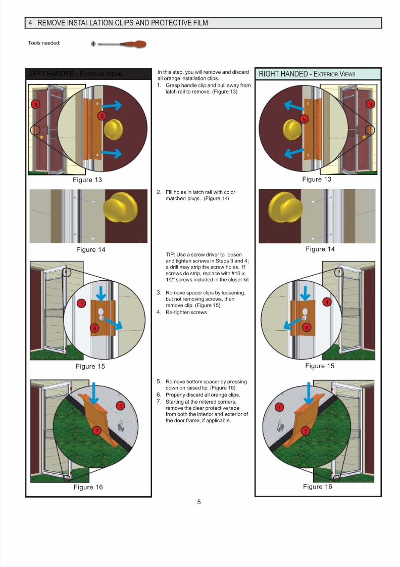
In this step, you will remove and discard
all orange installation clips.
Grasp handle clip and pull away from
latch rail to remove. (Figure 13)
Fill holes in latch rail with color
matched plugs. (Figure 14)
TIP: Use a screw driver to loosen
and tighten screws in Steps 3 and 4;
a drill may strip the screw holes. If
screws do strip, replace with #10 x
1/2” screws included in the closer kit
Remove spacer clips by loosening,
but not removing screws, thenremove clip. (Figure 15)
Re-tighten screws.
Remove bottom spacer by pressing
down on raised lip. (Figure 16)
Properly discard all orange clips.Starting at the mitered corners,
remove the clear protective tape
from both the interior and exterior of
the door frame, if applicable.
1.
2.
3.
4.
5.
6.7.
4. REMOVE INSTALLATION CLIPS AND PROTECTIVE FILM
Figure 13
Figure 16
Figure 15
5
6
1
1
7
3
Figure 14
Figure 13
Figure 16
Figure 15
Figure 14
5
6
1
3
1
7
7/24/2019 Stormdoor Install 6ddaef76 8e17 441b 99f7 275ceb2bc2a4
http://slidepdf.com/reader/full/stormdoor-install-6ddaef76-8e17-441b-99f7-275ceb2bc2a4 6/116
Tools needed:
In this step, you will install the
handle set.
Look into handle holes on door to
make sure lock case is oriented
properly. The notch in the
square spindle hole should be
facing away from the glass panel.
(Figure 17)
TIP: If the notch is not facing
away from the glass panel, use
the handle and spindle to rotate
the spindle hole into the correct
orientation
NOTE: Trim plates should not
be installed on the door while
completing steps 2 & 3.
Insert handle into outside trimplate (with Andersen logo) with
lever pointing down and rotate
the handle to secure it.
(Figure 18)
Repeat for other handle and
inside trim plate (with slider).
(Figure 19)
With handle levers held
horizontal, install both handleassemblies onto the door. The
spindle will pass through the
square hole in the lock case and
into the other handle. Attach trim
plates together using two #8 x 1
1/2” screws. (Figure 20)
Install lock case trim plate
onto lock case and fasten with
one #10 x 5/8” screw. Do not
overtighten. (Figure 21)
Insert dead bolt key cylinder
into lock case and fasten with
one #10 x 1 1/2” screw. Do not
overtighten. (Figure 22)
NOTE: This door features an
integrated latch receiver in the
latch rail, eliminating the need
for a traditional, separate strike
plate.
1.
2.
3.
4.
5.
6.
5. INSTALL HANDLE SET
RIGHT HANDED - EXTERIOR VIEWSLEFT HANDED - EXTERIOR VIEWS
Figure 17
Figure 18
Figure 19
Figure 20
Figure 17
Figure 18
Figure 19
2- #8 x 1 1/2”
Figure 20
Figure 21 Figure 22Figure 21 Figure 22
1- #10 x 1 1/2” 1- #10 x 5/8”
15
15
15
15
15
15
15
15
15
15
15
15
You can match your Andersen storm door
lock to Schlage or Kwikset entry door locks.
See handle set instructions contained within
handle set box for details.
“Kwikset” is a registered trademark of
Newfry LLC. “Schlage” is a registered
trademark of Schlage Lock Company.
G
L
A
S
S
G
L
A
S
S
11

7/24/2019 Stormdoor Install 6ddaef76 8e17 441b 99f7 275ceb2bc2a4
http://slidepdf.com/reader/full/stormdoor-install-6ddaef76-8e17-441b-99f7-275ceb2bc2a4 7/117
6. INSTALL RAIN CAP MOUNTING FLANGE, SCREW COVERS, AND WINDOW RETAINERS
Tools needed:
RIGHT HANDED - EXTERIOR VIEWSIn this step, you will install one of the
two rain cap mounting flanges provided.
Choose the rain cap mounting flange
that best covers the gap present
above the rain cap.
Hook rain cap mounting flange torain cap. (Figure 23)
While hooked, push up on rain cap
mounting flange and use the 1/8”
drill bit to a drill hole in the mounting
surface through the holes in the
flange. (Figure 24)
While pushing up on the rain cap
mounting flange, fasten flange to the
mounting surface with two #8 x 1”
screws. (Figure 24)
Starting with the rain cap screw
cover, insert a groove in the screw
cover into the bottom track of the
rain cap. (Figure 25)
Snap the groove in the top of the
screw cover into the top track of the
rain cap. (Figure 26).
Move accross screw cover, pressing
every few inches to snap into track
Repeat Steps 5 and 6 to install theremaining side screw covers.
Loosen but do not remove the two
screws attaching the sweep to the
door, lower the sweep until the
fins contact the door sill and then
re-tighten the screws. (Figure 27)
Lower the venting window so the
pre-drilled holes below the screen
are at a comfortable working height.
Align holes in window latch, insect
screen pull, and vent window, and
attach with two screws (Figure 28).
1.
2.
3.
4.
5.
6.
7.
8.
9.
10.
11.
LEFT HANDED - EXTERIOR VIEWS
BEFORE AFTER
Figure 25 Figure 26
BEFORE AFTER
Figure 25 Figure 26
Figure 24
Figure 23Figure 23
Figure 24
2 - #8x1” 8”1/8”
In this step, you will install the screw
covers over the mounting screws in the
rails and rain cap
Figure 27
In this step, you will adjust the sweep.
4
INTERIOR VIEW
NOTE: For additional seal against
rain, caulk above rain cap mounting
flange.
In this step, attach the window latch..
Figure 28
17
10
11
Figure 27
4
INTERIOR VIEW
Figure 28
17
10
11
2 - #6 x 3/4”
7/24/2019 Stormdoor Install 6ddaef76 8e17 441b 99f7 275ceb2bc2a4
http://slidepdf.com/reader/full/stormdoor-install-6ddaef76-8e17-441b-99f7-275ceb2bc2a4 8/118
RIGHT HANDED - INTERIOR VIEWS
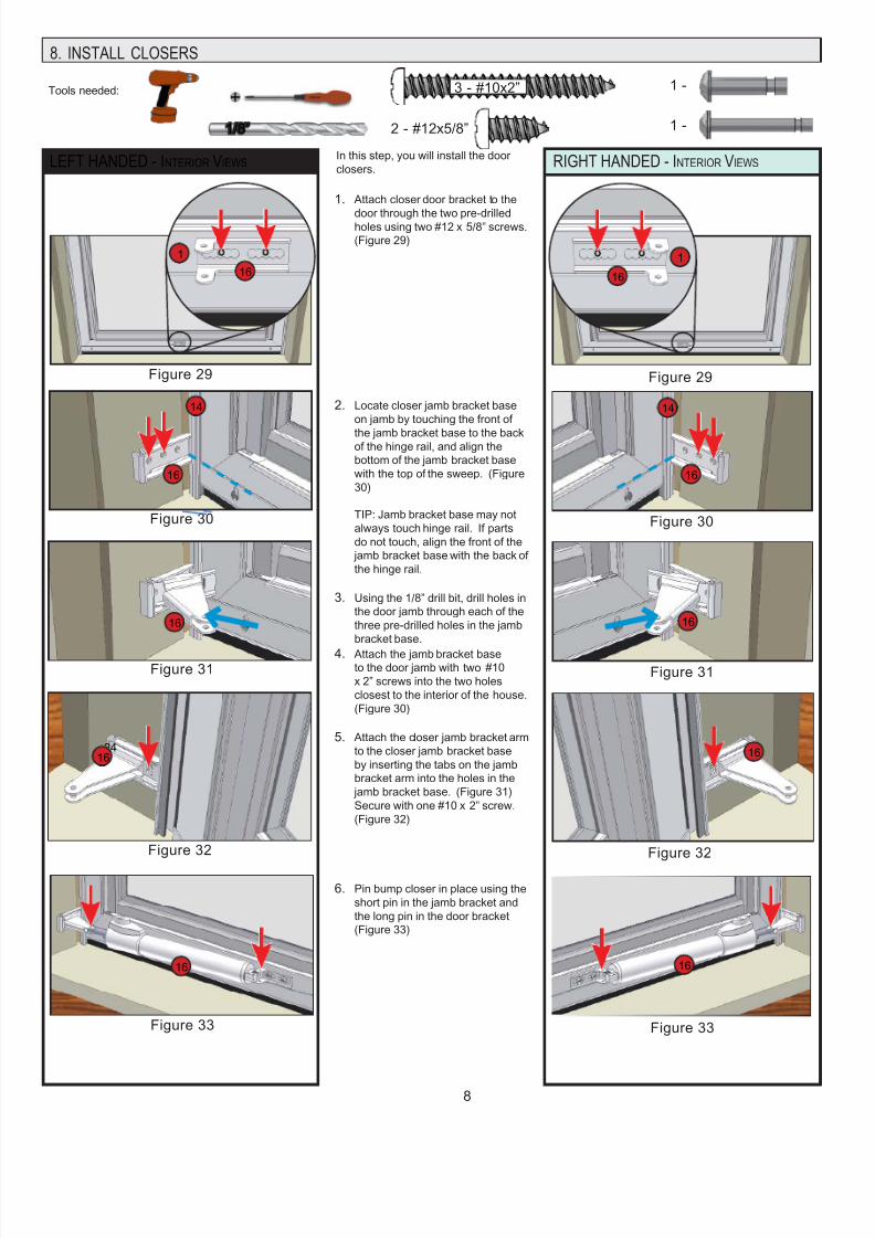
8. INSTALL CLOSERS
Tools needed: 3 - #10x2”
2 - #12x5/8”
LEFT HANDED - INTERIOR VIEWS
1 -
1 -
In this step, you will install the door
closers.
Attach closer door bracket to the
door through the two pre-drilledholes using two #12 x 5/8” screws.
(Figure 29)
Locate closer jamb bracket base
on jamb by touching the front of
the jamb bracket base to the backof the hinge rail, and align the
bottom of the jamb bracket base
with the top of the sweep. (Figure
30)
TIP: Jamb bracket base may not
always touch hinge rail. If parts
do not touch, align the front of the
jamb bracket base with the back of
the hinge rail.
Using the 1/8” drill bit, drill holes in
the door jamb through each of the
three pre-drilled holes in the jamb
bracket base.
Attach the jamb bracket baseto the door jamb with two #10
x 2” screws into the two holes
closest to the interior of the house.
(Figure 30)
Attach the closer jamb bracket arm
to the closer jamb bracket base
by inserting the tabs on the jamb
bracket arm into the holes in the
jamb bracket base. (Figure 31)
Secure with one #10 x 2” screw.
(Figure 32)
Pin bump closer in place using the
short pin in the jamb bracket and
the long pin in the door bracket
(Figure 33)
1.
2.
3.
4.
5.
6.
Figure 29
Figure 30
Figure 31
Figure 32
Figure 33
Figure 29
Figure 30
Figure 31
Figure 32
Figure 33
16
16 16
1616
24 16
1616
16
16
8”1/8”
1 1
14 14
7/24/2019 Stormdoor Install 6ddaef76 8e17 441b 99f7 275ceb2bc2a4
http://slidepdf.com/reader/full/stormdoor-install-6ddaef76-8e17-441b-99f7-275ceb2bc2a4 9/119
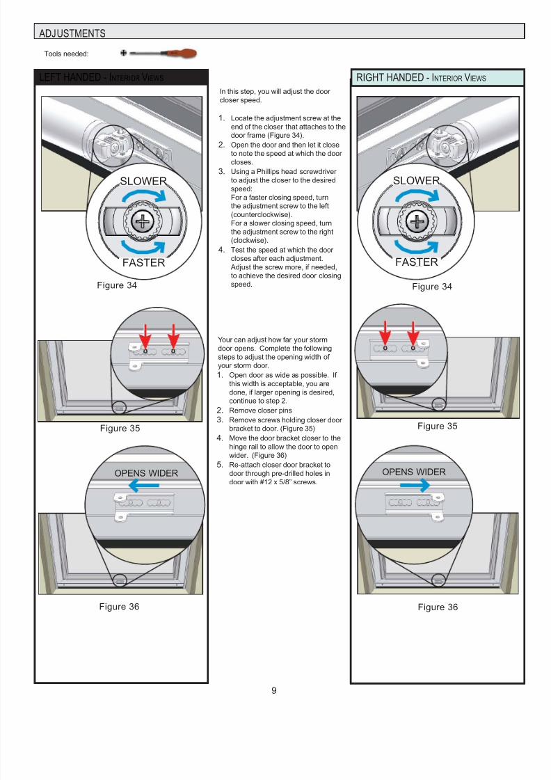
ADJUSTMENTS
LEFT HANDED - INTERIOR VIEWS RIGHT HANDED - INTERIOR VIEWS
Your can adjust how far your storm
door opens. Complete the following
steps to adjust the opening width of
your storm door.
Open door as wide as possible. If
this width is acceptable, you are
done, if larger opening is desired,
continue to step 2.
Remove closer pinsRemove screws holding closer door
bracket to door. (Figure 35)
Move the door bracket closer to the
hinge rail to allow the door to open
wider. (Figure 36)
Re-attach closer door bracket to
door through pre-drilled holes in
door with #12 x 5/8” screws.
1.
2.3.
4.
5.
In this step, you will adjust the door
closer speed.
Locate the adjustment screw at the
end of the closer that attaches to the
door frame (Figure 34).Open the door and then let it close
to note the speed at which the door
closes.
Using a Phillips head screwdriver
to adjust the closer to the desired
speed:
For a faster closing speed, turn
the adjustment screw to the left
(counterclockwise).
For a slower closing speed, turn
the adjustment screw to the right
(clockwise).
Test the speed at which the door
closes after each adjustment.
Adjust the screw more, if needed,
to achieve the desired door closingspeed.
1.
2.
3.
4.
Tools needed:
FASTER
SLOWER
Figure 34
FASTER
SLOWER
Figure 34
OPENS WIDEROPENS WIDER
Figure 36 Figure 36
Figure 35 Figure 35
7/24/2019 Stormdoor Install 6ddaef76 8e17 441b 99f7 275ceb2bc2a4
http://slidepdf.com/reader/full/stormdoor-install-6ddaef76-8e17-441b-99f7-275ceb2bc2a4 10/1110
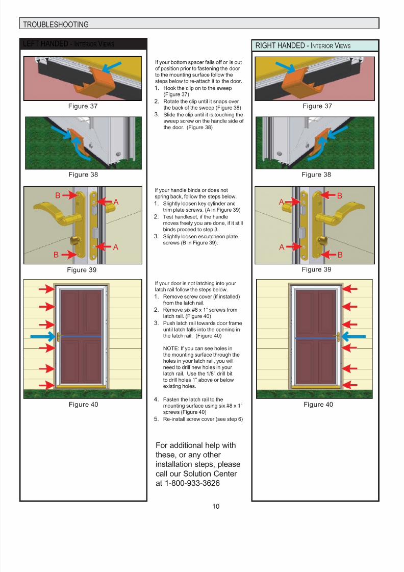
TROUBLESHOOTING
LEFT HANDED - INTERIOR VIEWS RIGHT HANDED - INTERIOR VIEWS
If your door is not latching into your
latch rail follow the steps below.
Remove screw cover (if installed)
from the latch rail.
Remove six #8 x 1” screws from
latch rail. (Figure 40)
Push latch rail towards door frame
until latch falls into the opening in
the latch rail. (Figure 40)
NOTE: If you can see holes in
the mounting surface through the
holes in your latch rail, you will
need to drill new holes in your
latch rail. Use the 1/8” drill bit
to drill holes 1” above or below
existing holes.
Fasten the latch rail to themounting surface using six #8 x 1”
screws (Figure 40)
Re-install screw cover (see step 6)
1.
2.
3.
4.
5.
Figure 40 Figure 40
Figure 38
If your bottom spacer falls off or is out
of position prior to fastening the door
to the mounting surface follow the
steps below to re-attach it to the door.
Hook the clip on to the sweep
(Figure 37)
Rotate the clip until it snaps overthe back of the sweep (Figure 38)
Slide the clip until it is touching the
sweep screw on the handle side of
the door. (Figure 38)
1.
2.
3.
Figure 37 Figure 37
Figure 38
If your handle binds or does not
spring back, follow the steps below.
Slightly loosen key cylinder and
trim plate screws. (A in Figure 39)
Test handleset, if the handle
moves freely you are done, if it still
binds proceed to step 3.
Slightly loosen escutcheon plate
screws (B in Figure 39).
1.
2.
3.
A
A
B
B
A
A
B
B
Figure 39 Figure 39
For additional help with
these, or any other
installation steps, please
call our Solution Center
at 1-800-933-3626
7/24/2019 Stormdoor Install 6ddaef76 8e17 441b 99f7 275ceb2bc2a4
http://slidepdf.com/reader/full/stormdoor-install-6ddaef76-8e17-441b-99f7-275ceb2bc2a4 11/11
LIMITED WARRANTIES
WINDOW GLASS – The glass may be cleaned with any household glass cleaner. Keep glass cleaners away from painted parts and brass/nickel components.
PLASTIC PARTS – Plastic door components may be cleaned by using a mild soap and water mixture and by gently rubbing the affected area. Do not use harsh abrasives or any prod
that contains chlorine.
ALUMINUM PARTS – Aluminum parts on the door may be cleaned by using a mild soap and water mixture and by gently rubbing the affected area. Mineral spirits may be used and w
not harm the paint. This will remove many items such as glue residue. Do not use harsh abrasives or any product that contains chlorine.
HANDLE COMPONENTS – Brass handles and components (except caming on windows) may be cleaned in the following manner: Brass handles and components are coated with a c
urethane finish which protects the brass from tarnishing. In order to clean the brass, this coating will have to be removed. Upon doing this, a larger area of brass will be exposed and s
ject to weathering. Use a high quality brass polish according to the specific directions on that product. A clear urethane may be reapplied to the clean surface to protect the finish. Pain
handles and components may be cleaned by using a mild soap and water mixture and by gently rubbing the affected area. Do not use harsh abrasives or any product that contain
chlorine.
ANODIZED FINISHED SWEEPS – The anodized finished sweep may be cleaned with a mild solution of soap and water. Do not use harsh abrasives or any product that contains chlo-
rine.
BRASS/NICKEL GLASS CLEANING – Brass and Nickel components may be cleaned with good quality cleaner; such as Brasso®.
REGULAR MAINTENANCE
PRODUCT LIMITED WARRANTY
DOOR FRAME: EMCO Enterprises, Inc. (EMCO) warrants the door frame, hinges, and painted finish on Andersen® aluminum storm door products to be free from defects in manufact
ing, materials, paint adhesion, or workmanship, under normal use, for as long as the original consumer purchaser owns the home in which the door was initially installed.
COMPONENTS: EMCO warrants the non-glass and non-insect screen fabric components of Andersen® storm doors (including brass and nickel hardware finish and the mechanical
functions of balancers, locksets, closers, windows and insect screens) to be free from defects in manufacturing, materials and workmanship for a period of five (5) years from the date o
original retail purchase or for as long as the original consumer purchaser owns the home in which the door was initially installed, whichever is shorter. Insulated glass is also warrante
for a period of five (5) years not to develop, under normal conditions, any material obstruction of vision resulting from manufacturing defects or as a result of premature failure of the glaor hermetic seal.
In the event a door frame, hinges, insulated glass or a component fails as a result of a defect in manufacturing, materials or workmanship within the limited warranty period specified
above, and upon written proof of purchase, EMCO, at its option, will provide a replacement door frame, hinge, insulated glass unit and/or components without charge – installation is no
included. Such replacement or repair is warranted for the remainder of the original limited warranty period. Please locate the door serial number and written proof of purchase and con
EMCO Consumer Support at 1-800-933-3626. Warranty claims made one (1) year after purchase are subject to a flat processing fee.
“ OOPS-PROOF” INSTALLATION LIMITED WARRANTY
EMCO Enterprises, Inc. (EMCO) warrants that any part lost or mis-cut during the original installation of your Andersen storm door will be repaired or replaced at no additional charge
within ninety (90) days of the date of original purchase. This limited warranty will not apply if the part has been misused, abused or altered. Cutting parts not specified by the installatio
guide or mis-drilled parts are not included in this warranty.
In the event a part is lost or mis-cut within the limited warranty period, EMCO, at its option, will provide the appropriate replacement part – installation is not included. Please locate the
door serial number and written proof of purchase and contact EMCO Consumer Support at 1-800-933-3626.
GENERAL LIMITED WARRANTY INFORMATION
The limited warranties set forth in this document are the only express warranties (whether written or oral) applicable to Andersen® storm doors, and no one is authorized to modify or
expand these limited warranties. All warranty claims must be made during the applicable warranty periods.
ALL IMPLIED WARRANTIES INCLUDING MERCHANTABILITY AND FITNESS FOR A PARTICULAR PURPOSE ARE LIMITED TO THE APPLICAB LE STATUTE OF LIMITATION
BUT IN NO CASE WILL EXTEND BEYOND THE TERM OF THE LIMITED WARRANTIES SET FORTH ABOVE. EMCO EXCLUDES AND WILL NOT PAY FOR INCIDENTAL OR
CONSEQUENTIAL DAMAGES, WHETHER ARISING OUT OF CONTRACT, TORT OR OTHERWISE, AND ITS LIABILITY WILL IN ALL INSTANCES BE LIMITED TO THE REPAIR
OR REPLACEMENT OF THE DEFECTIVE PRODUCT.
Some states do not allow the exclusion of incidental and consequential damages, or limitation of the duration of an implied warranty, so the above limitations or exclusions may not app
to you.
This limited warranty gives you specific legal rights, and you may also have other rights that may vary from state to state and in Canada.
What is NOT covered by this limited warranty: damage caused by 1) improper installation, maintenance, or use; 2) chemicals or airborne pollutants, such as salt or acidrain; 3) acts of God, including win d damage; 4) products not manufactured by EMCO
EMCO Enterprises, Inc. is a wholly owned subsidiary of Andersen Corporation. EMCO manufactures Andersen® and EMCO® storm doors. EMCO supports the limited warranties cov
ering Andersen® Storm and Screen Doors. “Andersen”, “EMCO” and all other marks where denoted are trademarks of Andersen Corporation. ©2011 Andersen Corporation. All rights
reserved.
Reprinted and effective as of May, 2011.


![Hand Lei Ding Interactieve Televisie Install a Tie Hoofdaansluiting Tcm14 1916[1]](https://static.fdocuments.nl/doc/165x107/5571f7ee49795991698c4d42/hand-lei-ding-interactieve-televisie-install-a-tie-hoofdaansluiting-tcm14-19161.jpg)