SPECIAL JUDGES AWARD BEST SOCIAL STATEMENT...The narra ve below is a summary of how Team B177 was...
105
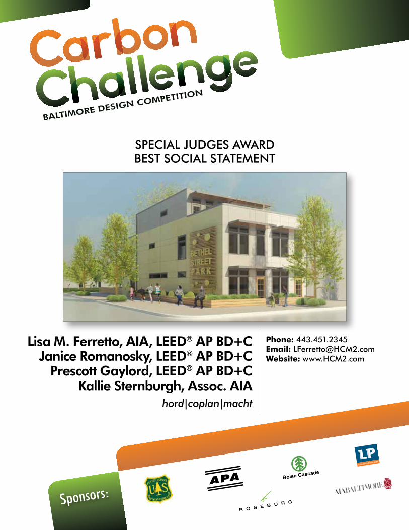
Sponsors: Lisa M. Ferretto, AIA, LEED ® AP BD+C Janice Romanosky, LEED ® AP BD+C Prescott Gaylord, LEED ® AP BD+C Kallie Sternburgh, Assoc. AIA hord|coplan|macht Phone: 443.451.2345 Email: [email protected] Website: www.HCM2.com SPECIAL JUDGES AWARD BEST SOCIAL STATEMENT
Transcript of SPECIAL JUDGES AWARD BEST SOCIAL STATEMENT...The narra ve below is a summary of how Team B177 was...
Sponsors:
Lisa M. Ferretto, AIA, LEED® AP BD+C Janice Romanosky, LEED® AP BD+C
Prescott Gaylord, LEED® AP BD+C Kallie Sternburgh, Assoc. AIA
hord|coplan|macht
Phone: 443.451.2345 Email: [email protected] Website: www.HCM2.com
SPECIAL JUDGES AWARD BEST SOCIAL STATEMENT
3
Project Approach and Neighborhood Loca on
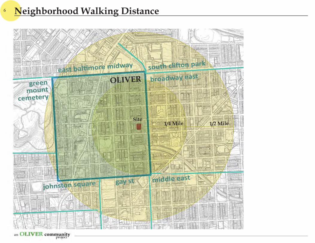
Neighborhood Walking Distance and Basic Services
Neighborhood Demographics
Community Past and Present
Exis ng Site Views
Exis ng Neighboring Blocks and Site Op ons
Proposed Site Plan and Aerial View
Proposed Views
Proposed Home Design
Green Building and Energy Standards
Sustainable Strategies: Energy and Water
Sustainable Strategies: Site, Materials and Indoor Environment
Costs and Aff ordability
APPENDIX
1: Energy Modeling Reports
2: Green Building Reports
3: Cost Es mate
4
6
8
10
12
14
16
18
20
22
24
26
27
Table of Contents
4
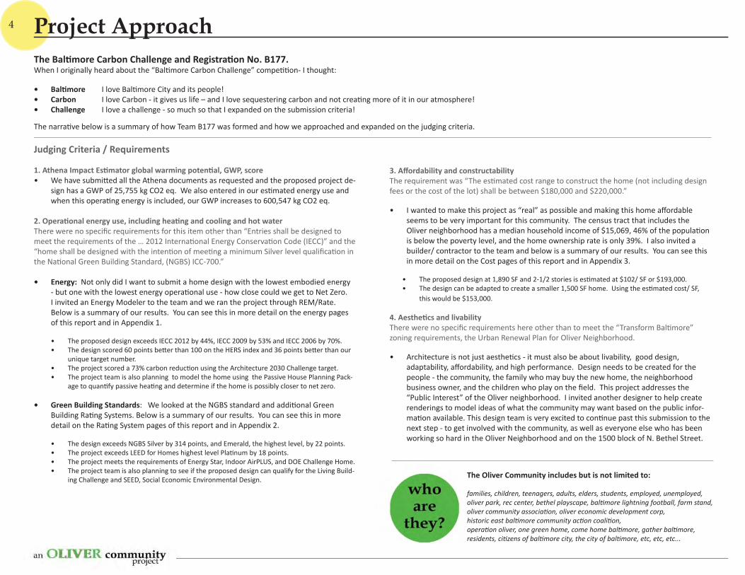
Judging Criteria / Requirements
1. Athena Impact Es mator global warming poten al, GWP, score • We have submi ed all the Athena documents as requested and the proposed project de-
sign has a GWP of 25,755 kg CO2 eq. We also entered in our es mated energy use and when this opera ng energy is included, our GWP increases to 600,547 kg CO2 eq.
2. Opera onal energy use, including hea ng and cooling and hot waterThere were no specifi c requirements for this item other than “Entries shall be designed to meet the requirements of the … 2012 Interna onal Energy Conserva on Code (IECC)” and the “home shall be designed with the inten on of mee ng a minimum Silver level qualifi ca on in the Na onal Green Building Standard, (NGBS) ICC-700.”
• Energy: Not only did I want to submit a home design with the lowest embodied energy - but one with the lowest energy opera onal use - how close could we get to Net Zero. I invited an Energy Modeler to the team and we ran the project through REM/Rate. Below is a summary of our results. You can see this in more detail on the energy pages of this report and in Appendix 1.
• The proposed design exceeds IECC 2012 by 44%, IECC 2009 by 53% and IECC 2006 by 70%. • The design scored 60 points be er than 100 on the HERS index and 36 points be er than our
unique target number. • The project scored a 73% carbon reduc on using the Architecture 2030 Challenge target. • The project team is also planning to model the home using the Passive House Planning Pack-
age to quan fy passive hea ng and determine if the home is possibly closer to net zero.
• Green Building Standards: We looked at the NGBS standard and addi onal Green Building Ra ng Systems. Below is a summary of our results. You can see this in more detail on the Ra ng System pages of this report and in Appendix 2.
• The design exceeds NGBS Silver by 314 points, and Emerald, the highest level, by 22 points.• The project exceeds LEED for Homes highest level Pla num by 18 points.• The project meets the requirements of Energy Star, Indoor AirPLUS, and DOE Challenge Home. • The project team is also planning to see if the proposed design can qualify for the Living Build-
ing Challenge and SEED, Social Economic Environmental Design.
3. Aff ordability and constructabilityThe requirement was “The es mated cost range to construct the home (not including design fees or the cost of the lot) shall be between $180,000 and $220,000.”
• I wanted to make this project as “real” as possible and making this home aff ordable seems to be very important for this community. The census tract that includes the Oliver neighborhood has a median household income of $15,069, 46% of the popula on is below the poverty level, and the home ownership rate is only 39%. I also invited a builder/ contractor to the team and below is a summary of our results. You can see this in more detail on the Cost pages of this report and in Appendix 3.
• The proposed design at 1,890 SF and 2-1/2 stories is es mated at $102/ SF or $193,000.• The design can be adapted to create a smaller 1,500 SF home. Using the es mated cost/ SF,
this would be $153,000.
4. Aesthe cs and livabilityThere were no specifi c requirements here other than to meet the “Transform Bal more” zoning requirements, the Urban Renewal Plan for Oliver Neighborhood.
• Architecture is not just aesthe cs - it must also be about livability, good design, adaptability, aff ordability, and high performance. Design needs to be created for the people - the community, the family who may buy the new home, the neighborhood business owner, and the children who play on the fi eld. This project addresses the “Public Interest” of the Oliver neighborhood. I invited another designer to help create renderings to model ideas of what the community may want based on the public infor-ma on available. This design team is very excited to con nue past this submission to the next step - to get involved with the community, as well as everyone else who has been working so hard in the Oliver Neighborhood and on the 1500 block of N. Bethel Street.
The Bal more Carbon Challenge and Registra on No. B177.When I originally heard about the “Bal more Carbon Challenge” compe on- I thought:
• Bal more I love Bal more City and its people! • Carbon I love Carbon - it gives us life – and I love sequestering carbon and not crea ng more of it in our atmosphere!• Challenge I love a challenge - so much so that I expanded on the submission criteria!
The narra ve below is a summary of how Team B177 was formed and how we approached and expanded on the judging criteria.
The Oliver Community includes but is not limited to:
families, children, teenagers, adults, elders, students, employed, unemployed,oliver park, rec center, bethel playscape, bal more lightning football, farm stand,oliver community associa on, oliver economic development corp,historic east bal more community ac on coali on,opera on oliver, one green home, come home bal more, gather bal more, residents, ci zens of bal more city, the city of bal more, etc, etc, etc...
Project Approach
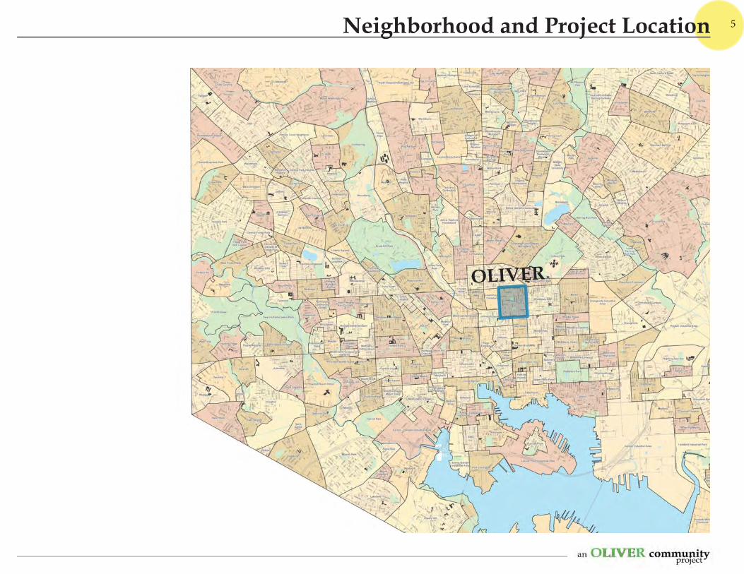
5
OLIVER
Neighborhood and Project Location
6
OLIVER
Site1/4 Mile 1/2 Mile
Neighborhood Walking Distance
7
OLIVER
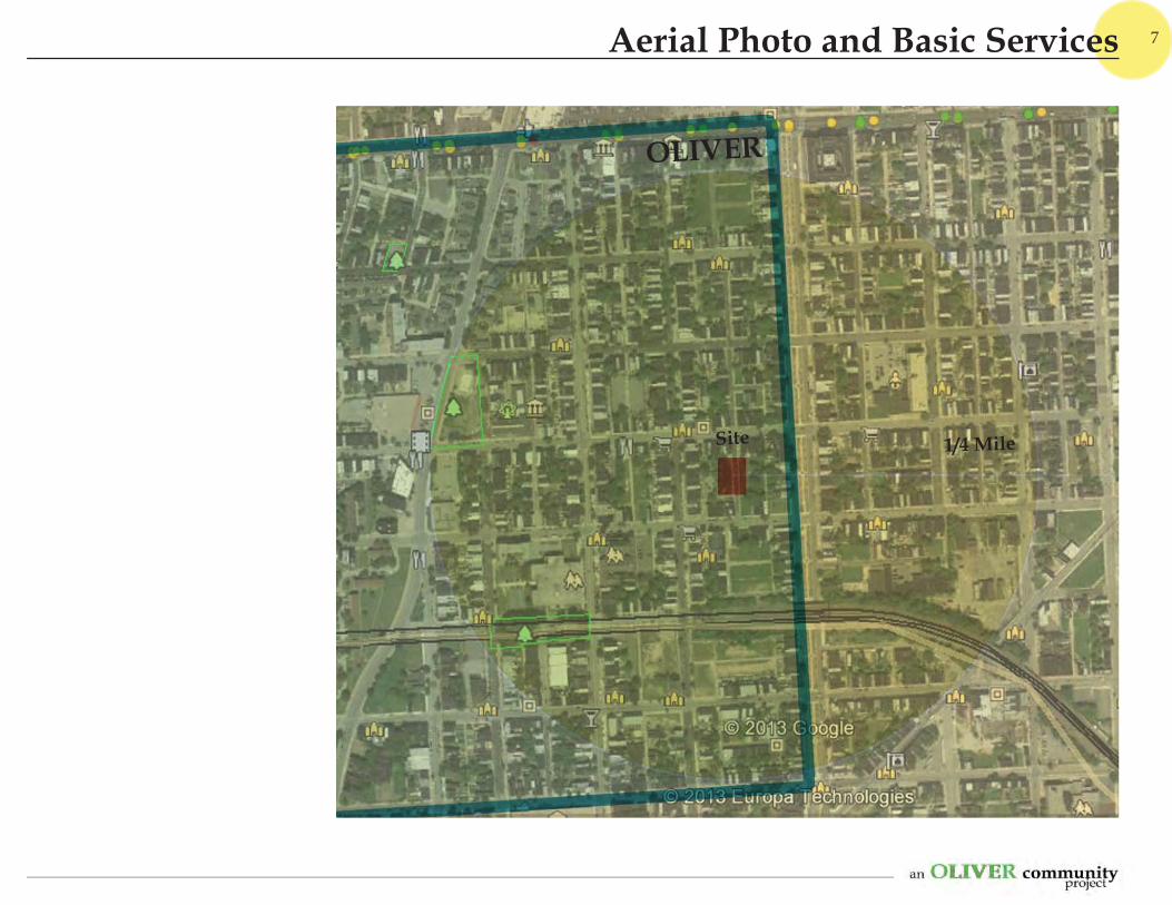
Site 1/4 Mile
Aerial Photo and Basic Services
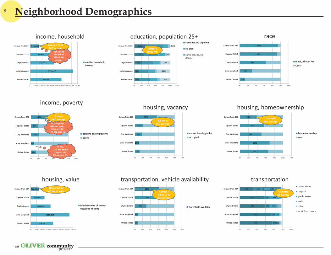
race
13%
30%
64%
92%
94%
0% 20% 40% 60% 80% 100% 120%
United States
State Maryland
City Baltimore
Zipcode 21213
Census Tract 807
Black, African Am.Other
education, population 25+
15%
12%
22%
27%
33%
28%
36%
26%
9%
0.2%
0% 20% 40% 60% 80% 100% 120%
United States
State Maryland
City Baltimore
Zipcode 21213
Census Tract 807
Some HS, No Diploma
HS grad
some college, nodegree
Almost 3times MD
income, household
$52,762
$72,417
$40,100
$34,499
$15,069
$ $10,000 $20,000 $30,000 $40,000 $50,000 $60,000 $70,000 $80,000
United States
State Maryland
City Baltimore
Zipcode 21213
Census Tract 807
median householdincome
Almost 1/5 ofMD income
61% spendmore than35% of this
on rent
income, poverty
14%
9%
22%
19%
46%
0% 20% 40% 60% 80% 100% 120%
United States
State Maryland
City Baltimore
Zipcode 21213
Census Tract 807
persons below povertyabove
5 timesMD average
Of this group66% are under18 years old.
45% are over 65.
In MD,12% are below18 years old.
8% are over 65.
housing, vacancy
12%
10%
19%
21%
56%
0% 20% 40% 60% 80% 100% 120%
United States
State Maryland
City Baltimore
Zipcode 21213
Census Tract 807
vacant housing unitsoccupied
5.6 timesMD average
housing, homeownership
66%
69%
50%
57%
39%
0% 20% 40% 60% 80% 100% 120%
United States
State Maryland
City Baltimore
Zipcode 21213
Census Tract 807
home ownershiprent
Over halfMD average
housing, value
$186,200
$319,800
$163,700
$114,000
$68,100
$0 $50,000 $100,000 $150,000 $200,000 $250,000 $300,000 $350,000
United States
State Maryland
City Baltimore
Zipcode 21213
Census Tract 807
Median value of owneroccupied housing
Almost 1/5 ofMD home value
transportation, vehicle availability
9%
9%
30%
66%
61%
0% 20% 40% 60% 80% 100% 120%
United States
State Maryland
City Baltimore
Zipcode 21213
Census Tract 807
No vehicle available
Almost 7times US &MD average
transportation
76%
73%
60%
57%
31%
10%
11%
11%
13%
25%
5%
9%
18%
23%
40%
0% 20% 40% 60% 80% 100% 120%
United States
State Maryland
City Baltimore
Zipcode 21213
Census Tract 807drove alone
carpool
public trans.
walk
other
work from home
4.4 timesUS average
8 Neighborhood Demographics
9
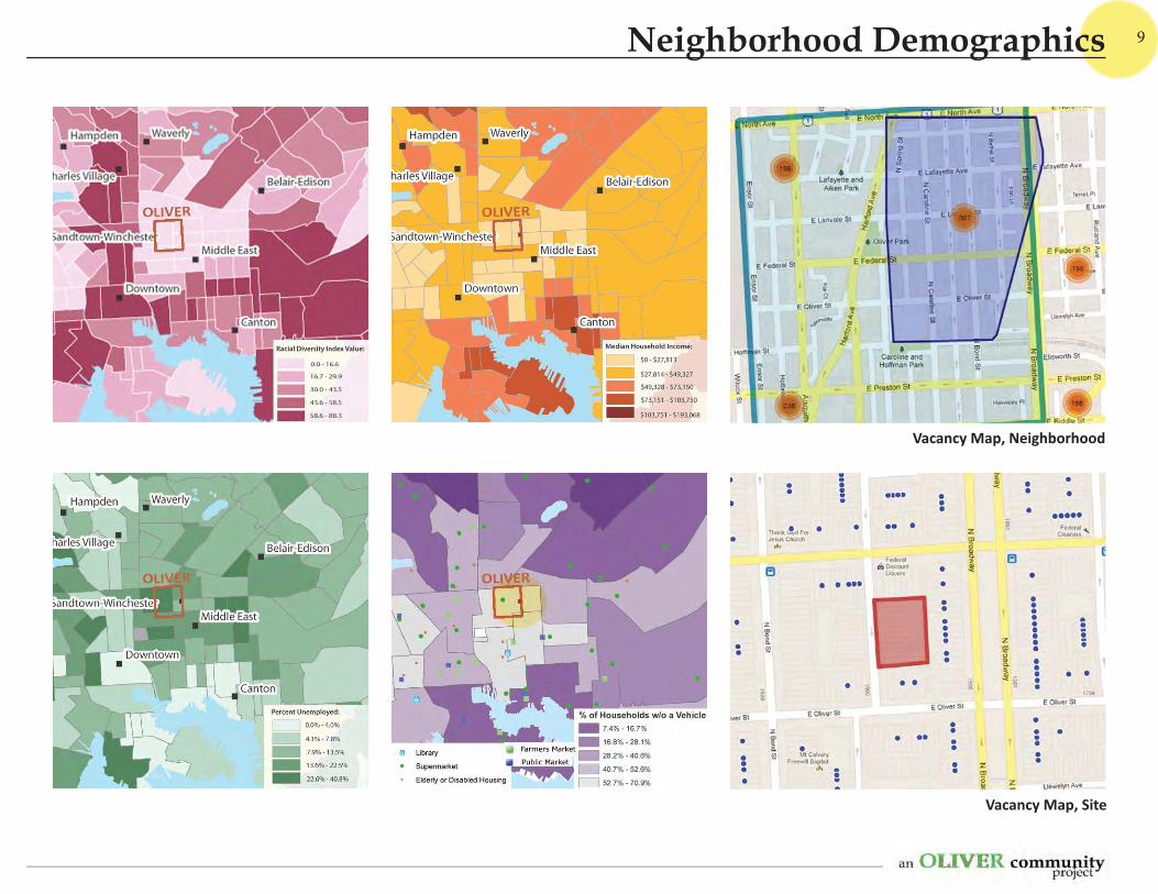
Vacancy Map, Site
Vacancy Map, Neighborhood
Neighborhood Demographics

10
...to“Bethel St. Playscape” and “Lightning Field” text and photos from Briony Hynson and Playgroundism h p://playgroundism.tumblr.com/
Back in October [2012], a sign appeared on Bethel Street announcing the greatest thing to hit Bal more in a long me— the Bal more Lightning football team.
Neighborhood kids are ge ng organized and playing ball daily a er school at the lot. The yellow circles are soon to be yard line markers ... By marking the 50/40/30/20/10 yard lines and end zones on the sidewalk, the kids will have a ... reference for the fi eld.
The Bal more Lightning, a “team” of approximately 10-15 kids, ages ranging from 9-13, has held football prac- ce every day since about mid-October at the Bethel St.
Playscape, on what we now refer to as “Lightning Field.”
From “Murderland Alley...” www.imdb.com/ tle/ 0306414/ and www2.citypaper.com/bob/story.asp?id=11846
The Wire HBO television series premiered in 2002, and ended in 2008. The 1500 block of N. Bethel Street was known as “Murderland Alley” and was the home of the “Bodymore Murdaland” graffi that appeared in the show’s opening credits.
Community Past Community Present

11
photos Briony Hynson, Playgroundism; h p://playgroundism.tumblr.com/
Community Present
12
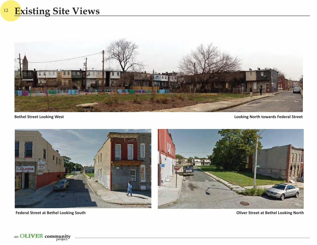
Bethel Street Looking West Looking North towards Federal Street
Federal Street at Bethel Looking South Oliver Street at Bethel Looking North
Existing Site Views
13
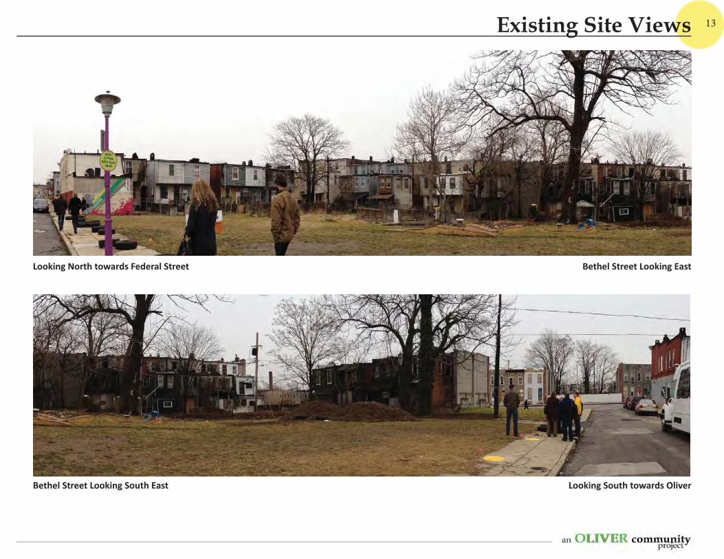
Bethel Street Looking East
Looking South towards OliverBethel Street Looking South East
Looking North towards Federal Street
Existing Site Views
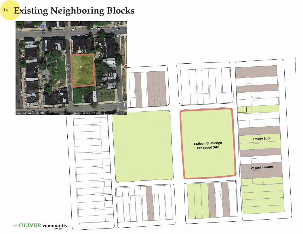
14 Existing Neighboring Blocks
15
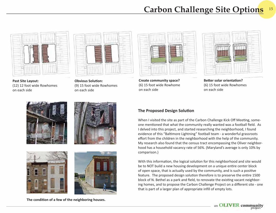
Past Site Layout: (12) 12 foot wide Rowhomeson each side
Obvious Solu on: (9) 15 foot wide Rowhomes on each side
Create community space? (6) 15 foot wide Rowhomeon each side
Be er solar orienta on? (6) 15 foot wide Rowhomes on each side
The Proposed Design Solu on
When I visited the site as part of the Carbon Challenge Kick Off Mee ng, some-one men oned that what the community really wanted was a football fi eld. As I delved into this project, and started researching the neighborhood, I found evidence of this “Bal more Lightning” football team - a wonderful grassroots eff ort from the children in the neighborhood with the help of the community. My research also found that the census tract encompassing the Oliver neighbor-hood has a household vacancy rate of 56%. (Maryland’s average is only 10% by comparison.)
With this informa on, the logical solu on for this neighborhood and site would be to NOT build a new housing development on a unique en re center block of open space, that is actually used by the community, and is such a posi ve feature. The proposed design solu on therefore is to preserve the en re 1500 block of N. Bethel as a park and fi eld, to renovate the exis ng vacant neighbor-ing homes, and to propose the Carbon Challenge Project on a diff erent site - one that is part of a larger plan of appropriate infi ll of empty lots.
The condi on of a few of the neighboring houses.
Carbon Challenge Site Options
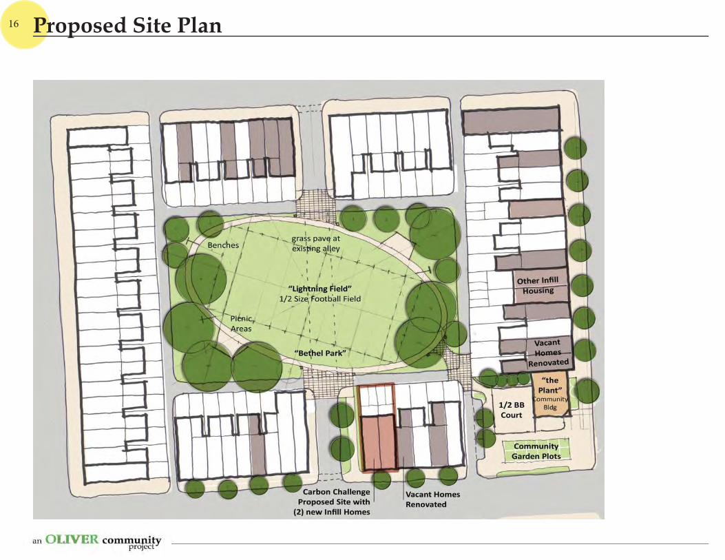
16 Proposed Site Plan
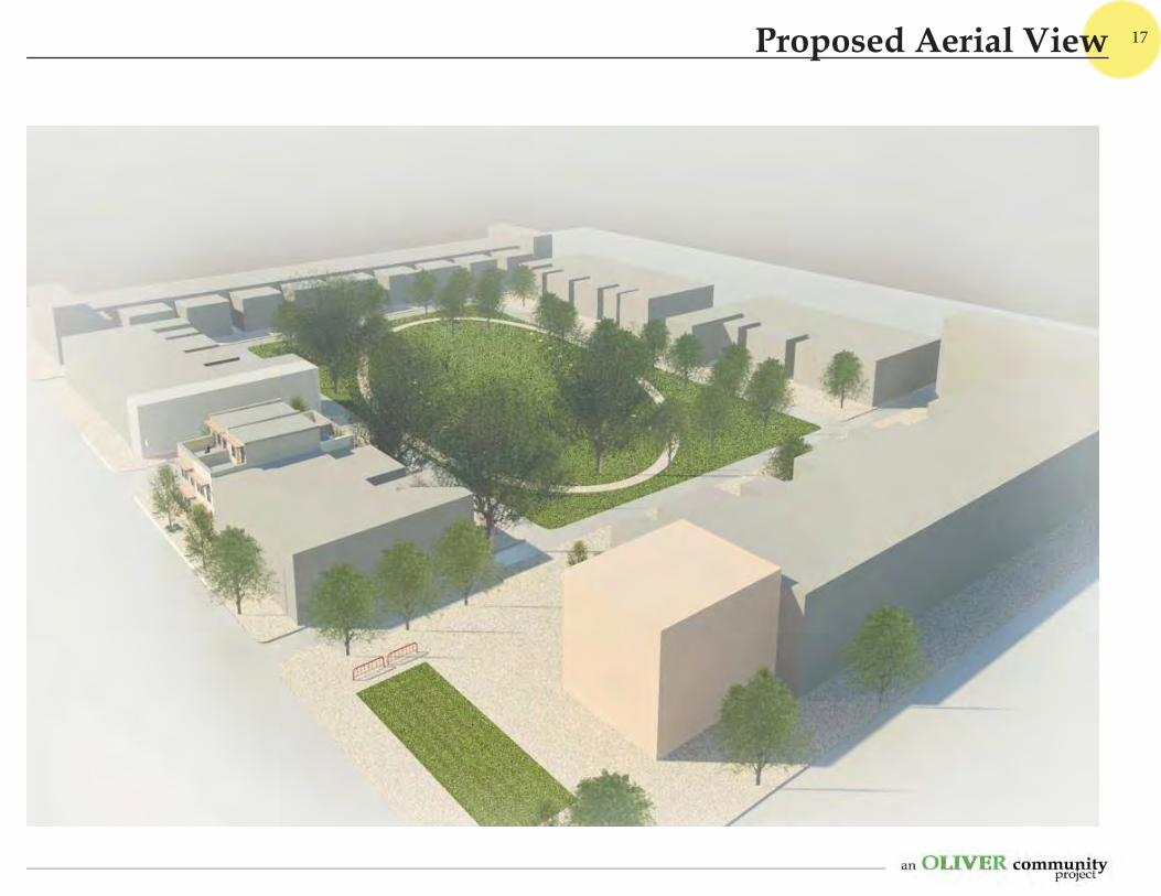
17Proposed Aerial View
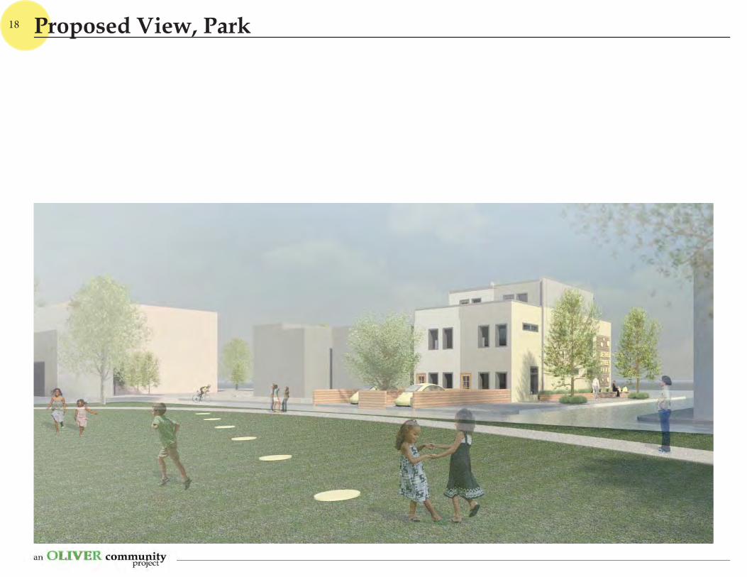
18 Proposed View, Park
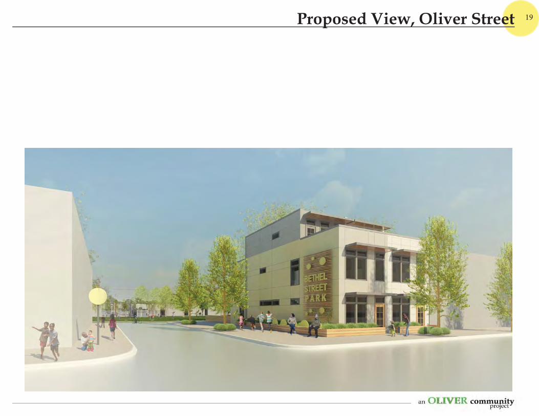
19Proposed View, Oliver Street
20
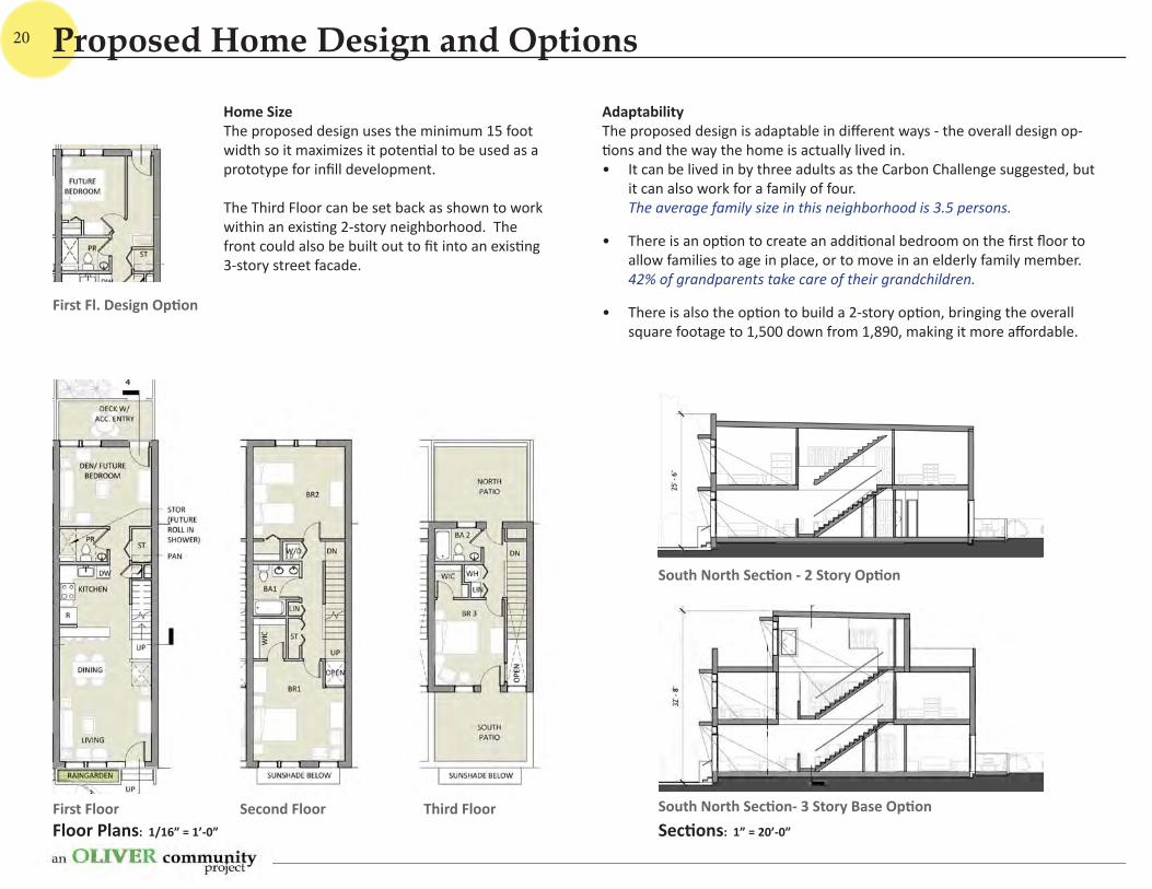
Floor Plans: 1/16” = 1’-0”
First Floor Second Floor Third FloorSec ons: 1” = 20’-0”
South North Sec on - 2 Story Op on
South North Sec on- 3 Story Base Op on
First Fl. Design Op on
Adaptability The proposed design is adaptable in diff erent ways - the overall design op- ons and the way the home is actually lived in.
• It can be lived in by three adults as the Carbon Challenge suggested, but it can also work for a family of four. The average family size in this neighborhood is 3.5 persons.
• There is an op on to create an addi onal bedroom on the fi rst fl oor to allow families to age in place, or to move in an elderly family member.42% of grandparents take care of their grandchildren.
• There is also the op on to build a 2-story op on, bringing the overall square footage to 1,500 down from 1,890, making it more aff ordable.
Home SizeThe proposed design uses the minimum 15 foot width so it maximizes it poten al to be used as a prototype for infi ll development.
The Third Floor can be set back as shown to work within an exis ng 2-story neighborhood. The front could also be built out to fi t into an exis ng 3-story street facade.
Proposed Home Design and Options
21
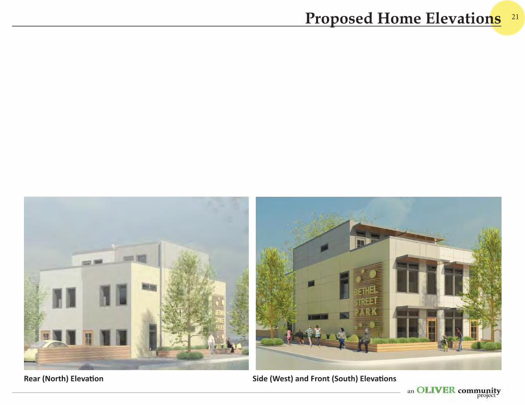
Rear (North) Eleva on Side (West) and Front (South) Eleva ons
Proposed Home Elevations
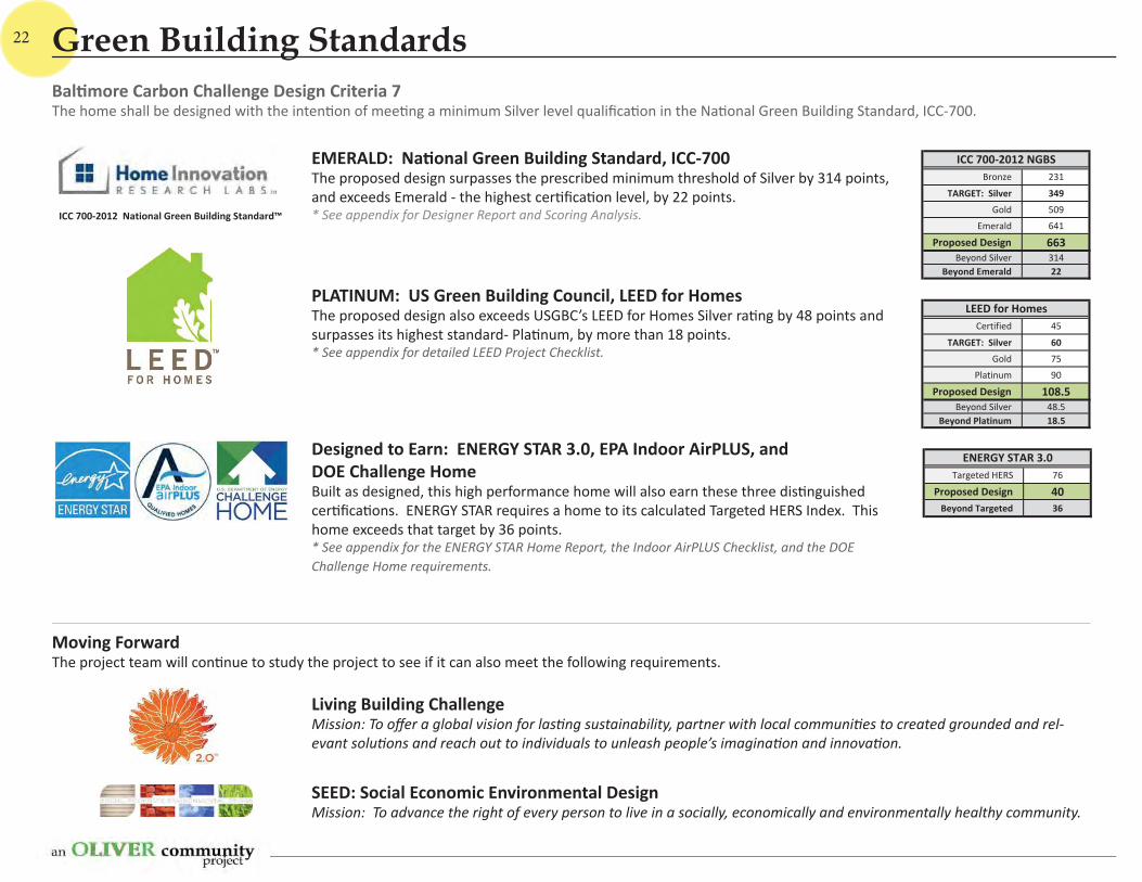
Bronze 231
TARGET: Silver 349Gold 509
Emerald 641
Proposed Design 663Beyond Silver 314
Beyond Emerald 22
ICC 700 2012 NGBS
Certified 45
TARGET: Silver 60Gold 75
Platinum 90
Proposed Design 108.5Beyond Silver 48.5
Beyond Platinum 18.5
LEED for Homes
ICC 700 2012 National Green Building Standard™
Targeted HERS 76
Proposed Design 40Beyond Targeted 36
ENERGY STAR 3.0
22
EMERALD: Na onal Green Building Standard, ICC-700The proposed design surpasses the prescribed minimum threshold of Silver by 314 points, and exceeds Emerald - the highest cer fi ca on level, by 22 points. * See appendix for Designer Report and Scoring Analysis.
PLATINUM: US Green Building Council, LEED for HomesThe proposed design also exceeds USGBC’s LEED for Homes Silver ra ng by 48 points and surpasses its highest standard- Pla num, by more than 18 points.* See appendix for detailed LEED Project Checklist.
Moving ForwardThe project team will con nue to study the project to see if it can also meet the following requirements.
Living Building ChallengeMission: To off er a global vision for las ng sustainability, partner with local communi es to created grounded and rel-evant solu ons and reach out to individuals to unleash people’s imagina on and innova on.
SEED: Social Economic Environmental DesignMission: To advance the right of every person to live in a socially, economically and environmentally healthy community.
Designed to Earn: ENERGY STAR 3.0, EPA Indoor AirPLUS, and DOE Challenge HomeBuilt as designed, this high performance home will also earn these three dis nguished cer fi ca ons. ENERGY STAR requires a home to its calculated Targeted HERS Index. This home exceeds that target by 36 points. * See appendix for the ENERGY STAR Home Report, the Indoor AirPLUS Checklist, and the DOE Challenge Home requirements.
Bal more Carbon Challenge Design Criteria 7The home shall be designed with the inten on of mee ng a minimum Silver level qualifi ca on in the Na onal Green Building Standard, ICC-700.
Green Building Standards
23
ProposedDesign
2012IECC
2009IECC
2006IECC
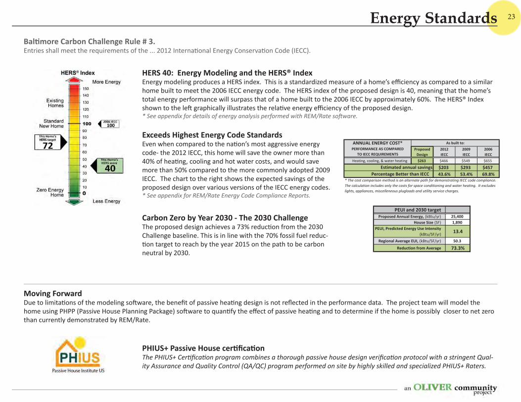
Heating, cooling, & water heating $263 $466 $549 $655
$203 $293 $45743.6% 53.4% 69.8%
Estimated annual savings
ANNUAL ENERGY COST*PERFORMANCE AS COMPARED
TO IECC REQUIREMENTS
As built to:
Percentage Better than IECC* The cost comparison method is an alternate path for demonstrating IECC code compliance.The calculation includes only the costs for space conditioning and water heating. It excludeslights, appliances, miscelleneous plugloads and utility service charges.
PEUI and 2030 targetProposed Annual Energy, (kBtu/yr) 25,400
House Size (SF) 1,890PEUI, Predicted Energy Use Intensity
(kBtu/SF/yr) 13.4
Regional Average EUI, (kBtu/SF/yr) 50.3
Reduction from Average 73.3%
PHIUS+ Passive House cer fi ca on The PHIUS+ Cer fi ca on program combines a thorough passive house design verifi ca on protocol with a stringent Qual-ity Assurance and Quality Control (QA/QC) program performed on site by highly skilled and specialized PHIUS+ Raters.
Moving ForwardDue to limita ons of the modeling so ware, the benefi t of passive hea ng design is not refl ected in the performance data. The project team will model the home using PHPP (Passive House Planning Package) so ware to quan fy the eff ect of passive hea ng and to determine if the home is possibly closer to net zero than currently demonstrated by REM/Rate.
Exceeds Highest Energy Code StandardsEven when compared to the na on’s most aggressive energy code- the 2012 IECC, this home will save the owner more than 40% of hea ng, cooling and hot water costs, and would save more than 50% compared to the more commonly adopted 2009 IECC. The chart to the right shows the expected savings of the proposed design over various versions of the IECC energy codes. * See appendix for REM/Rate Energy Code Compliance Reports.
Carbon Zero by Year 2030 - The 2030 Challenge The proposed design achieves a 73% reduc on from the 2030 Challenge baseline. This is in line with the 70% fossil fuel reduc- on target to reach by the year 2015 on the path to be carbon
neutral by 2030.
HERS 40: Energy Modeling and the HERS® IndexEnergy modeling produces a HERS index. This is a standardized measure of a home’s effi ciency as compared to a similar home built to meet the 2006 IECC energy code. The HERS index of the proposed design is 40, meaning that the home’s total energy performance will surpass that of a home built to the 2006 IECC by approximately 60%. The HERS® Index shown to the le graphically illustrates the rela ve energy effi ciency of the proposed design. * See appendix for details of energy analysis performed with REM/Rate so ware.
Bal more Carbon Challenge Rule # 3.Entries shall meet the requirements of the ... 2012 Interna onal Energy Conserva on Code (IECC).
Energy Standards
HeatingCoolingWater HeatingAppliancesLightingElectronicsOther
Energy UseEnergy Savings
24
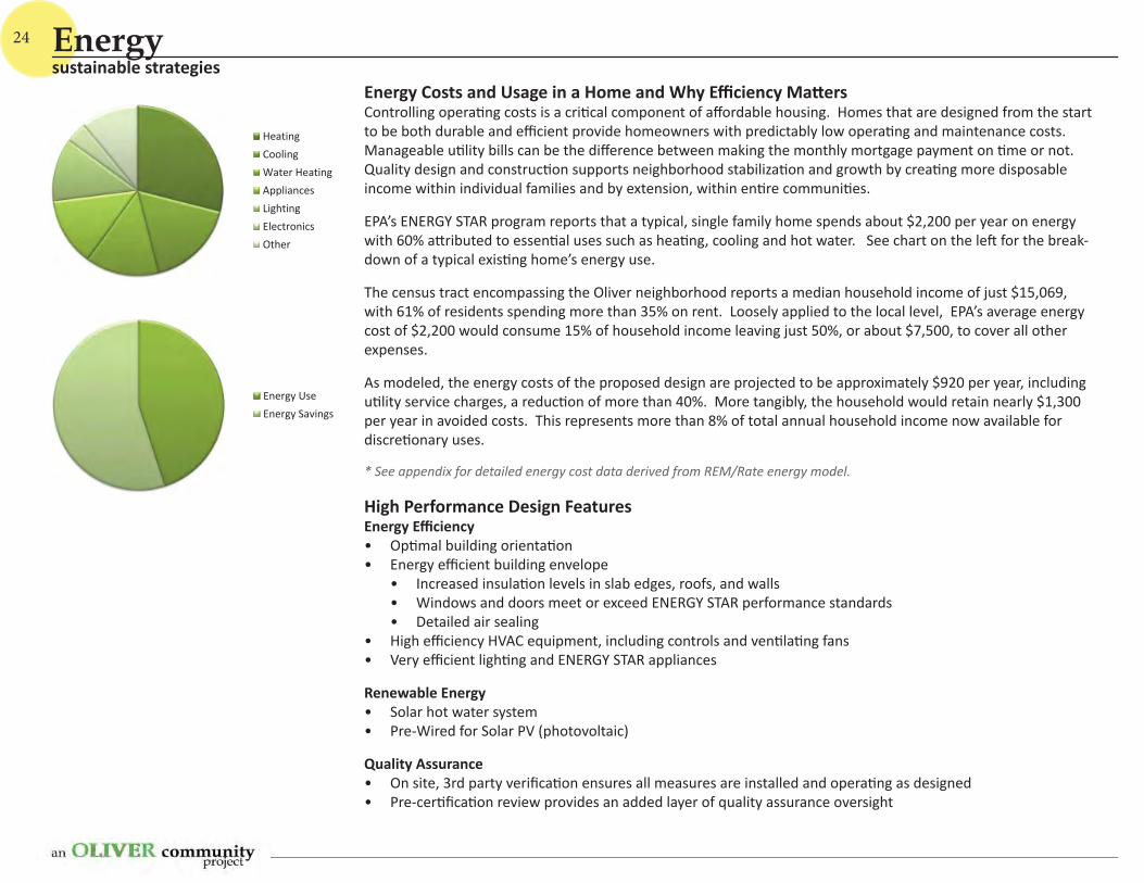
Energy Costs and Usage in a Home and Why Effi ciency Ma ersControlling opera ng costs is a cri cal component of aff ordable housing. Homes that are designed from the start to be both durable and effi cient provide homeowners with predictably low opera ng and maintenance costs. Manageable u lity bills can be the diff erence between making the monthly mortgage payment on me or not. Quality design and construc on supports neighborhood stabiliza on and growth by crea ng more disposable income within individual families and by extension, within en re communi es.
EPA’s ENERGY STAR program reports that a typical, single family home spends about $2,200 per year on energy with 60% a ributed to essen al uses such as hea ng, cooling and hot water. See chart on the le for the break-down of a typical exis ng home’s energy use.
The census tract encompassing the Oliver neighborhood reports a median household income of just $15,069, with 61% of residents spending more than 35% on rent. Loosely applied to the local level, EPA’s average energy cost of $2,200 would consume 15% of household income leaving just 50%, or about $7,500, to cover all other expenses.
As modeled, the energy costs of the proposed design are projected to be approximately $920 per year, including u lity service charges, a reduc on of more than 40%. More tangibly, the household would retain nearly $1,300 per year in avoided costs. This represents more than 8% of total annual household income now available for discre onary uses.
* See appendix for detailed energy cost data derived from REM/Rate energy model.
High Performance Design FeaturesEnergy Effi ciency• Op mal building orienta on• Energy effi cient building envelope
• Increased insula on levels in slab edges, roofs, and walls • Windows and doors meet or exceed ENERGY STAR performance standards• Detailed air sealing
• High effi ciency HVAC equipment, including controls and ven la ng fans• Very effi cient ligh ng and ENERGY STAR appliances
Renewable Energy• Solar hot water system• Pre-Wired for Solar PV (photovoltaic)
Quality Assurance• On site, 3rd party verifi ca on ensures all measures are installed and opera ng as designed• Pre-cer fi ca on review provides an added layer of quality assurance oversight
sustainable strategiesEnergy
25
ToiletClothes WasherShowerFaucetLeaksOther
Water UseWater Savings
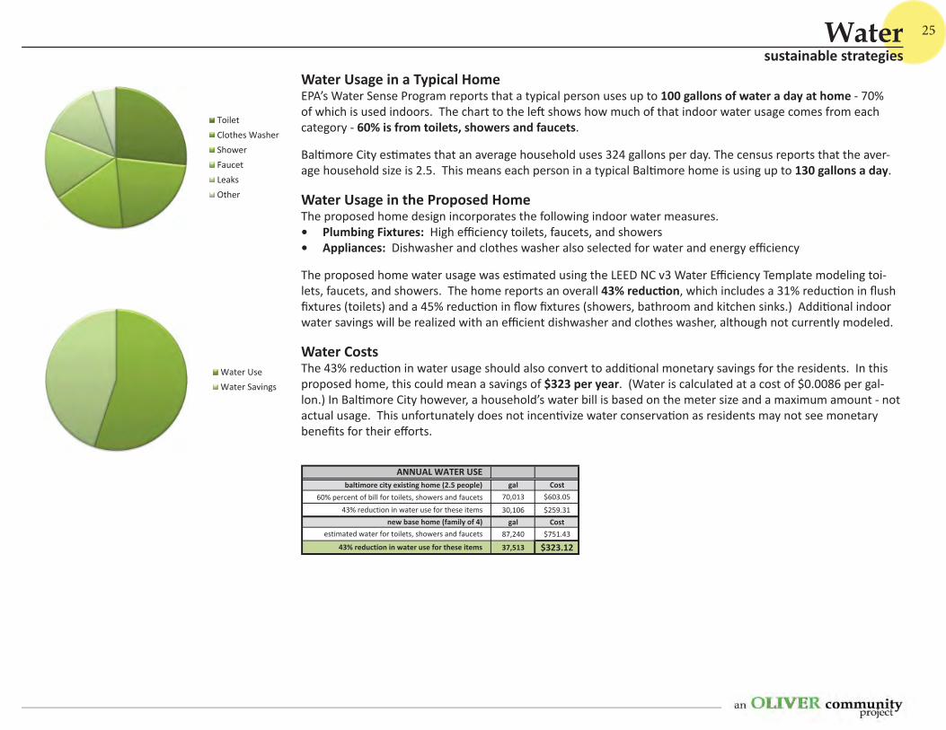
ANNUAL WATER USEbaltimore city existing home (2.5 people) gal Cost
60% percent of bill for toilets, showers and faucets 70,013 $603.05
43% reduction in water use for these items 30,106 $259.31new base home (family of 4) gal Cost
estimated water for toilets, showers and faucets 87,240 $751.43
43% reduction in water use for these items 37,513 $323.12
Water Usage in a Typical HomeEPA’s Water Sense Program reports that a typical person uses up to 100 gallons of water a day at home - 70% of which is used indoors. The chart to the le shows how much of that indoor water usage comes from each category - 60% is from toilets, showers and faucets.
Bal more City es mates that an average household uses 324 gallons per day. The census reports that the aver-age household size is 2.5. This means each person in a typical Bal more home is using up to 130 gallons a day.
Water Usage in the Proposed Home The proposed home design incorporates the following indoor water measures.• Plumbing Fixtures: High effi ciency toilets, faucets, and showers• Appliances: Dishwasher and clothes washer also selected for water and energy effi ciency
The proposed home water usage was es mated using the LEED NC v3 Water Effi ciency Template modeling toi-lets, faucets, and showers. The home reports an overall 43% reduc on, which includes a 31% reduc on in fl ush fi xtures (toilets) and a 45% reduc on in fl ow fi xtures (showers, bathroom and kitchen sinks.) Addi onal indoor water savings will be realized with an effi cient dishwasher and clothes washer, although not currently modeled.
Water CostsThe 43% reduc on in water usage should also convert to addi onal monetary savings for the residents. In this proposed home, this could mean a savings of $323 per year. (Water is calculated at a cost of $0.0086 per gal-lon.) In Bal more City however, a household’s water bill is based on the meter size and a maximum amount - not actual usage. This unfortunately does not incen vize water conserva on as residents may not see monetary benefi ts for their eff orts.
sustainable strategiesWater
26
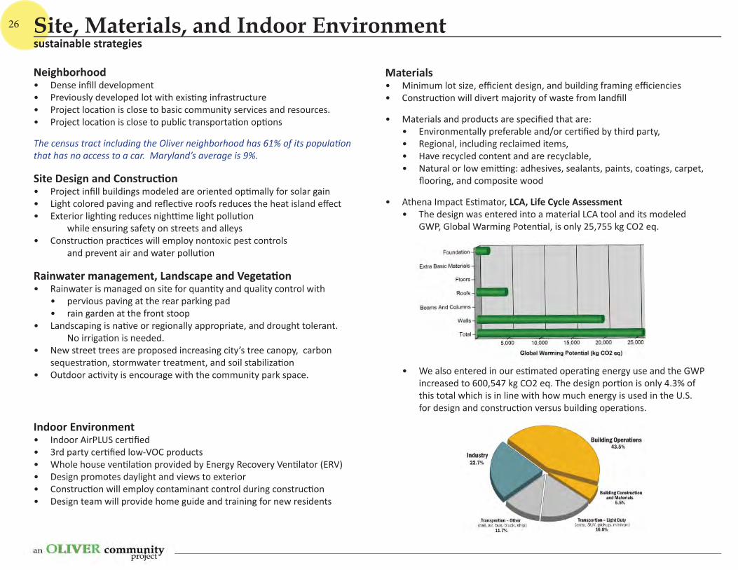
Materials• Minimum lot size, effi cient design, and building framing effi ciencies• Construc on will divert majority of waste from landfi ll
• Materials and products are specifi ed that are: • Environmentally preferable and/or cer fi ed by third party,• Regional, including reclaimed items,• Have recycled content and are recyclable,• Natural or low emi ng: adhesives, sealants, paints, coa ngs, carpet,
fl ooring, and composite wood
• Athena Impact Es mator, LCA, Life Cycle Assessment• The design was entered into a material LCA tool and its modeled
GWP, Global Warming Poten al, is only 25,755 kg CO2 eq.
• We also entered in our es mated opera ng energy use and the GWP increased to 600,547 kg CO2 eq. The design por on is only 4.3% of this total which is in line with how much energy is used in the U.S. for design and construc on versus building opera ons.
Neighborhood• Dense infi ll development • Previously developed lot with exis ng infrastructure• Project loca on is close to basic community services and resources.• Project loca on is close to public transporta on op ons
The census tract including the Oliver neighborhood has 61% of its popula on that has no access to a car. Maryland’s average is 9%.
Site Design and Construc on• Project infi ll buildings modeled are oriented op mally for solar gain• Light colored paving and refl ec ve roofs reduces the heat island eff ect• Exterior ligh ng reduces nigh me light pollu on while ensuring safety on streets and alleys• Construc on prac ces will employ nontoxic pest controls and prevent air and water pollu on
Rainwater management, Landscape and Vegeta on• Rainwater is managed on site for quan ty and quality control with
• pervious paving at the rear parking pad • rain garden at the front stoop
• Landscaping is na ve or regionally appropriate, and drought tolerant. No irriga on is needed.
• New street trees are proposed increasing city’s tree canopy, carbon sequestra on, stormwater treatment, and soil stabiliza on
• Outdoor ac vity is encourage with the community park space.
Indoor Environment• Indoor AirPLUS cer fi ed • 3rd party cer fi ed low-VOC products• Whole house ven la on provided by Energy Recovery Ven lator (ERV)• Design promotes daylight and views to exterior• Construc on will employ contaminant control during construc on• Design team will provide home guide and training for new residents
sustainable strategiesSite, Materials, and Indoor Environment
27
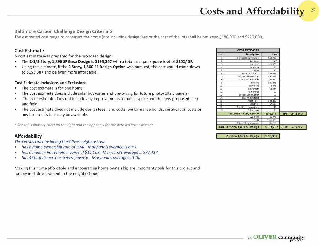
Div Description Cost1 General Requirements $13,7182 Site Work NIC3 Concrete $18,1794 Masonry $05 Metals $06 Wood and Plastic $43,3597 Thermal and Moisture $20,7918 Doors and Windows $7,8879 Finishes $30,475
10 Specialties $67511 Equipment $8,93412 Furnishings $013 Special Construction $014 Conveying Systems $015 Mechanical $24,43616 Electrical $7,69017 Third Party Inspections $018 Allowances $0
$176,144 $93 Cost per SF$5,284
$10,569$1,270
$193,267 $102 Cost per SF
$153,3872 Story, 1,500 SF Design
Total 3 Story, 1,890 SF Design
ProfitBuilders Risk Insurance
COST ESTIMATE
SubTotal 3 Story, 1,890 SFOverhead
Cost Es mateA cost es mate was prepared for the proposed design: • The 2-1/2 Story, 1,890 SF Base Design is $193,267 with a total cost per square foot of $102/ SF. • Using this es mate, if the 2 Story, 1,500 SF Design Op on was pursued, the cost would come down
to $153,387 and be even more aff ordable.
Cost Es mate Inclusions and Exclusions• The cost es mate is for one home.• The cost es mate does include solar hot water and pre-wiring for future photovoltaic panels. • The cost es mate does not include any improvements to public space and the new proposed park
and fi eld.• The cost es mate does not include design fees, land costs, performance bonds, cer fi ca on costs or
any tax credits that may be available.
* See the summary chart on the right and the appendix for the detailed cost es mate.
Aff ordabilityThe census tract including the Oliver neighborhood • has a home ownership rate of 39%. Maryland’s average is 69%. • has a median household income of $15,069. Maryland’s average is $72,417. • has 46% of its persons below poverty. Maryland’s average is 12%.
Making this home aff ordable and encouraging home ownership are important goals for this project and for any infi ll development in the neighborhood.
Bal more Carbon Challenge Design Criteria 6The es mated cost range to construct the home (not including design fees or the cost of the lot) shall be between $180,000 and $220,000.
Costs and Affordability

Appendix 1
ENERGY REPORTS
ENERGY STAR VERSION 3 HOME REPORT
Date: March 01, 2013 Rating No.:
Property: Rating Org.:
Baltimore, MD Rater's Name:
Builder's Name: Rater's ID:
Building Name: Carbon Chal inside Rating Date:
REM/Rate - Residential Energy Analysis and Rating Software v13.0
This information does not constitute any warranty of energy cost or savings. © 1985-2012 Architectural Energy Corporation, Boulder, Colorado.
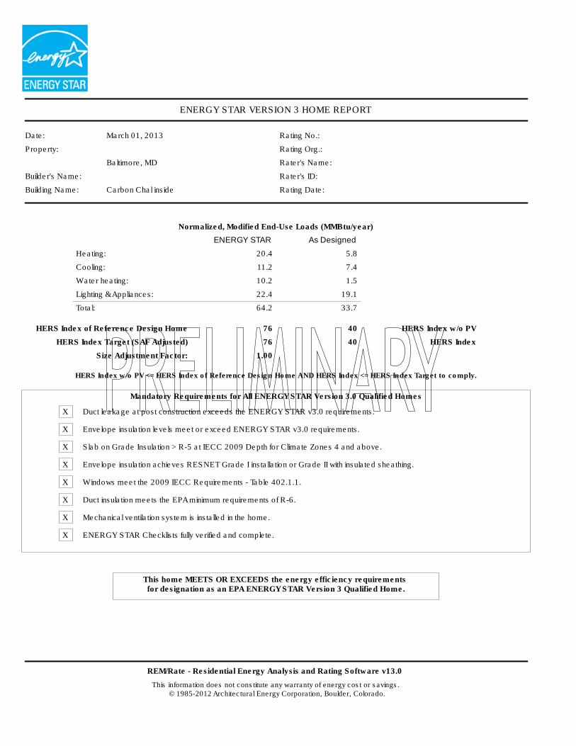
Normalized, Modified End-Use Loads (MMBtu/year)
ENERGY STAR As Designed
Heating: 20.4 5.8
Cooling: 11.2 7.4
Water heating: 10.2 1.5
Lighting & Appliances: 22.4 19.1
Total: 64.2 33.7
HERS Index of Reference Design Home 76 40 HERS Index w/o PV
HERS Index Target (SAF Adjusted) 76 40 HERS Index
Size Adjustment Factor: 1.00
HERS Index w/o PV <= HERS Index of Reference Design Home AND HERS Index <= HERS Index Target to comply.
Mandatory Requirements for All ENERGY STAR Version 3.0 Qualified Homes
X Duct leakage at post construction exceeds the ENERGY STAR v3.0 requirements.
X Envelope insulation levels meet or exceed ENERGY STAR v3.0 requirements.
X Slab on Grade Insulation > R-5 at IECC 2009 Depth for Climate Zones 4 and above.
X Envelope insulation achieves RESNET Grade I installation or Grade II with insulated sheathing.
X Windows meet the 2009 IECC Requirements - Table 402.1.1.
X Duct insulation meets the EPA minimum requirements of R-6.
X Mechanical ventilation system is installed in the home.
X ENERGY STAR Checklists fully verified and complete.
This home MEETS OR EXCEEDS the energy efficiency requirements for designation as an EPA ENERGY STAR Version 3 Qualified Home.
ENERGY STAR VERSION 3 HOME REPORT
Carbon Chal inside Page 2
REM/Rate - Residential Energy Analysis and Rating Software v13.0
© 1985-2012 Architectural Energy Corporation, Boulder, Colorado.
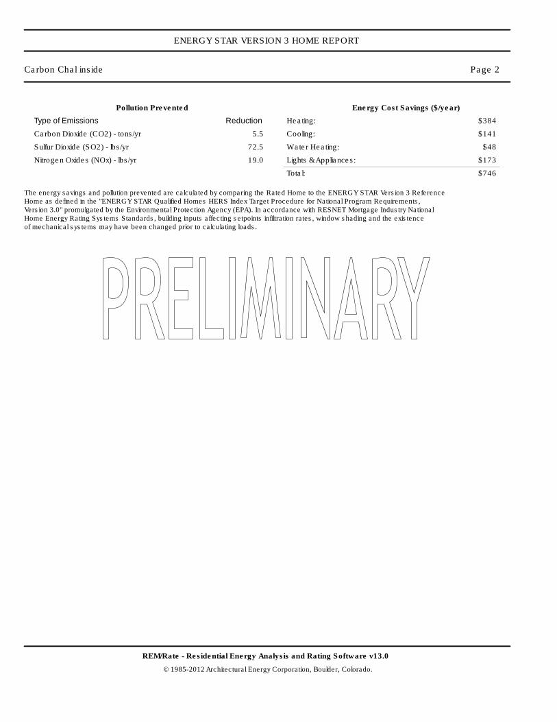
Pollution Prevented
Type of Emissions Reduction
Carbon Dioxide (CO2) - tons/yr 5.5
Sulfur Dioxide (SO2) - lbs/yr 72.5
Nitrogen Oxides (NOx) - lbs/yr 19.0
Energy Cost Savings ($/year)
Heating: $384
Cooling: $141
Water Heating: $48
Lights & Appliances: $173
Total: $746
The energy savings and pollution prevented are calculated by comparing the Rated Home to the ENERGY STAR Version 3 Reference Home as defined in the "ENERGY STAR Qualified Homes HERS Index Target Procedure for National Program Requirements, Version 3.0" promulgated by the Environmental Protection Agency (EPA). In accordance with RESNET Mortgage Industry National Home Energy Rating Systems Standards, building inputs affecting setpoints infiltration rates, window shading and the existence of mechanical systems may have been changed prior to calculating loads.
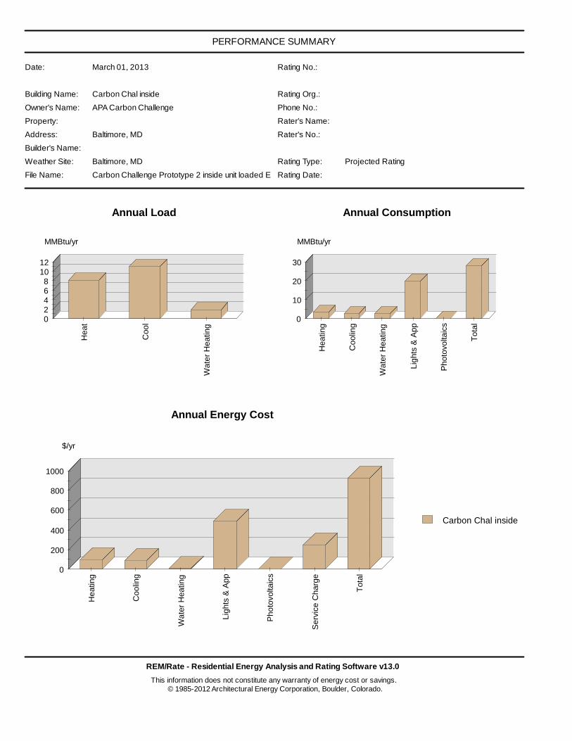
PERFORMANCE SUMMARY
Date: March 01, 2013 Rating No.:
Building Name: Carbon Chal inside Rating Org.:
Owner's Name: APA Carbon Challenge Phone No.:
Property: Rater's Name:
Address: Baltimore, MD Rater's No.:
Builder's Name:
Weather Site: Baltimore, MD Rating Type: Projected Rating
File Name: Carbon Challenge Prototype 2 inside unit loaded ERV.blgRating Date:
REM/Rate - Residential Energy Analysis and Rating Software v13.0
This information does not constitute any warranty of energy cost or savings. © 1985-2012 Architectural Energy Corporation, Boulder, Colorado.
02468
1012
Heat
Cool
Wate
r H
eating
MMBtu/yr
Annual Load
0
10
20
30
Heating
Coolin
g
Wate
r H
eating
Lig
hts
& A
pp
Photo
voltaic
s
Tota
l
MMBtu/yr
Annual Consumption
0
200
400
600
800
1000
Heating
Coolin
g
Wate
r H
eating
Lig
hts
& A
pp
Photo
voltaic
s
Serv
ice C
harg
e
Tota
l
$/yr
Annual Energy Cost
Carbon Chal inside
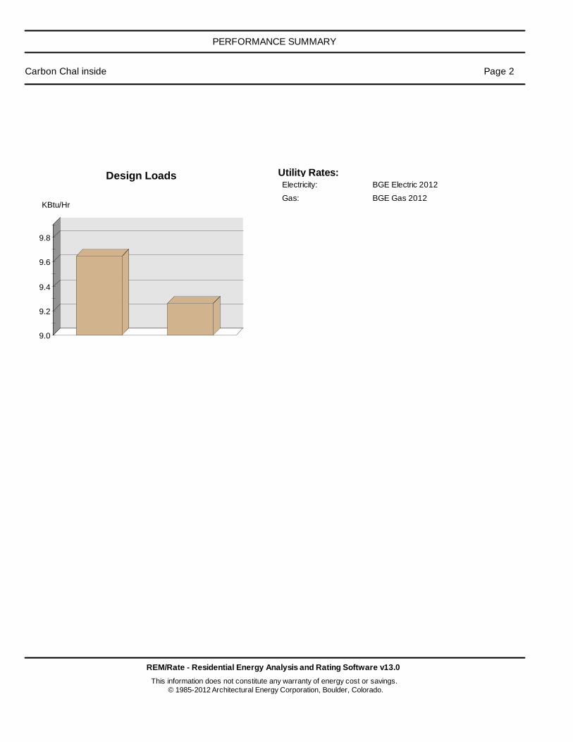
PERFORMANCE SUMMARY
Carbon Chal inside Page 2
REM/Rate - Residential Energy Analysis and Rating Software v13.0
This information does not constitute any warranty of energy cost or savings. © 1985-2012 Architectural Energy Corporation, Boulder, Colorado.
9.0
9.2
9.4
9.6
9.8
KBtu/Hr
Design Loads Utility Rates: Electricity: BGE Electric 2012
Gas: BGE Gas 2012
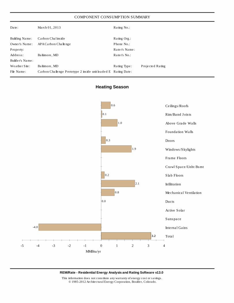
COMPONENT CONSUMPTION SUMMARY
Date: March 01, 2013 Rating No.:
Building Name: Carbon Chal inside Rating Org.:
Owner's Name: APA Carbon Challenge Phone No.:
Property: Rater's Name:
Address: Baltimore, MD Rater's No.:
Builder's Name:
Weather Site: Baltimore, MD Rating Type: Projected Rating
File Name: Carbon Challenge Prototype 2 inside unit loaded ERV.blgRating Date:
REM/Rate - Residential Energy Analysis and Rating Software v13.0
This information does not constitute any warranty of energy cost or savings. © 1985-2012 Architectural Energy Corporation, Boulder, Colorado.
-5 -4 -3 -2 -1 0 1 2 3 4
Ceilings/Roofs
Rim/Band Joists
Above Grade Walls
Foundation Walls
Doors
Windows/Skylights
Frame Floors
Crawl Space/Unht Bsmt
Slab Floors
Infiltration
Mechanical Ventilation
Ducts
Active Solar
Sunspace
Internal Gains
Total
MMBtu/yr
Heating Season
0.6
0.1
1.0
0.3
1.9
0.2
2.1
0.8
0.0
-4.0
3.23.2
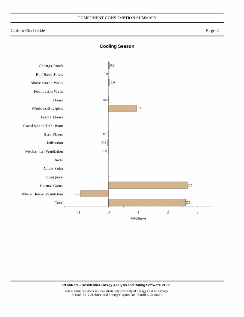
COMPONENT CONSUMPTION SUMMARY
Carbon Chal inside Page 2
REM/Rate - Residential Energy Analysis and Rating Software v13.0
This information does not constitute any warranty of energy cost or savings. © 1985-2012 Architectural Energy Corporation, Boulder, Colorado.
-1 0 1 2 3
Ceilings/Roofs
Rim/Band Joists
Above Grade Walls
Foundation Walls
Doors
Windows/Skylights
Frame Floors
Crawl Space/Unht Bsmt
Slab Floors
Infiltration
Mechanical Ventilation
Ducts
Active Solar
Sunspace
Internal Gains
Whole House Ventilation
Total
MMBtu/yr
Cooling Season
0.0
-0.0
0.0
-0.0
1.0
-0.0
-0.1
-0.0
2.7
-1.0
2.62.6
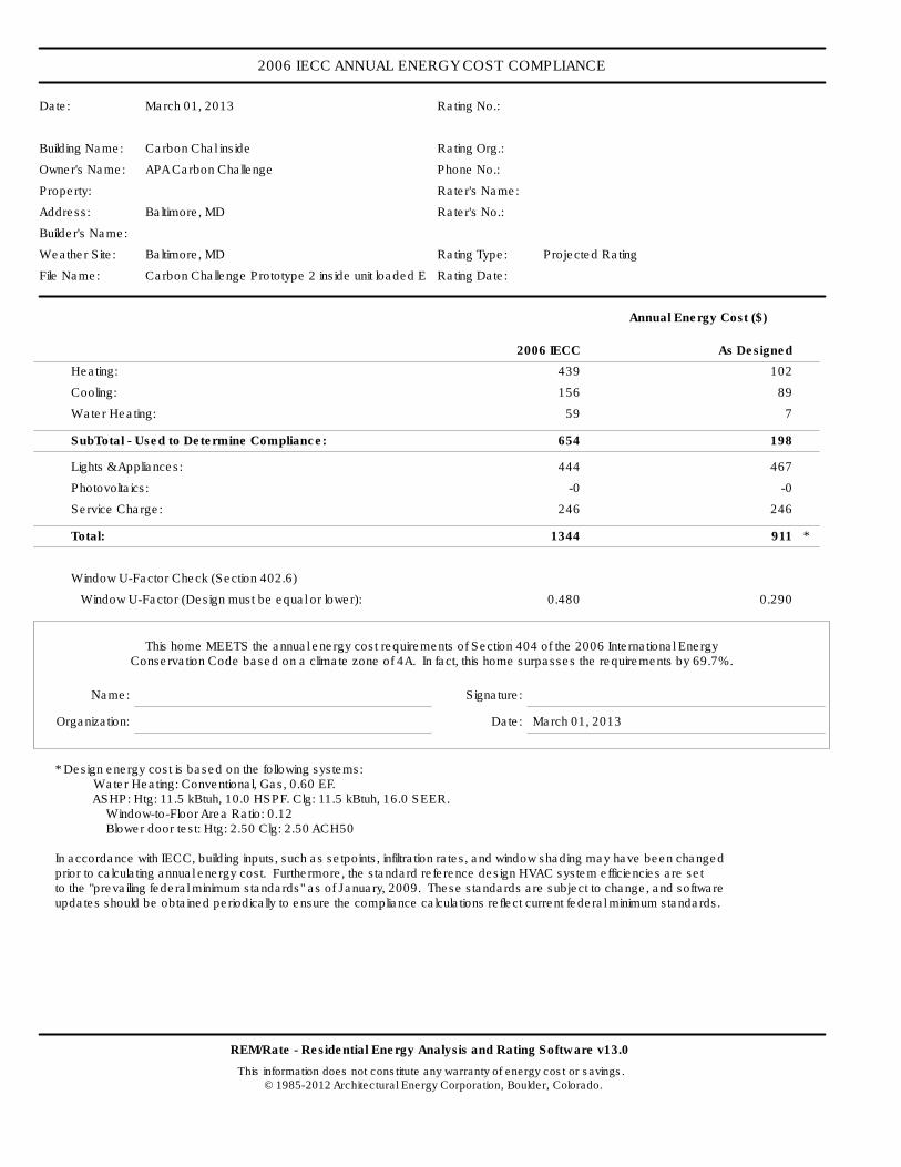
2006 IECC ANNUAL ENERGY COST COMPLIANCE
Date: March 01, 2013 Rating No.:
Building Name: Carbon Chal inside Rating Org.:
Owner's Name: APA Carbon Challenge Phone No.:
Property: Rater's Name:
Address: Baltimore, MD Rater's No.:
Builder's Name:
Weather Site: Baltimore, MD Rating Type: Projected Rating
File Name: Carbon Challenge Prototype 2 inside unit loaded ERV.blgRating Date:
REM/Rate - Residential Energy Analysis and Rating Software v13.0
This information does not constitute any warranty of energy cost or savings. © 1985-2012 Architectural Energy Corporation, Boulder, Colorado.
Annual Energy Cost ($)
2006 IECC As Designed
Heating: 439 102
Cooling: 156 89
Water Heating: 59 7
SubTotal - Used to Determine Compliance: 654 198
Lights & Appliances: 444 467
Photovoltaics: -0 -0
Service Charge: 246 246
Total: 1344 911 *
Window U-Factor Check (Section 402.6)
Window U-Factor (Design must be equal or lower): 0.480 0.290
This home MEETS the annual energy cost requirements of Section 404 of the 2006 International EnergyConservation Code based on a climate zone of 4A. In fact, this home surpasses the requirements by 69.7%.
Name: Signature:
Organization: Date: March 01, 2013
* Design energy cost is based on the following systems: Water Heating: Conventional, Gas, 0.60 EF. ASHP: Htg: 11.5 kBtuh, 10.0 HSPF. Clg: 11.5 kBtuh, 16.0 SEER. Window-to-Floor Area Ratio: 0.12 Blower door test: Htg: 2.50 Clg: 2.50 ACH50
In accordance with IECC, building inputs, such as setpoints, infiltration rates, and window shading may have been changed prior to calculating annual energy cost. Furthermore, the standard reference design HVAC system efficiencies are set to the "prevailing federal minimum standards" as of January, 2009. These standards are subject to change, and software updates should be obtained periodically to ensure the compliance calculations reflect current federal minimum standards.
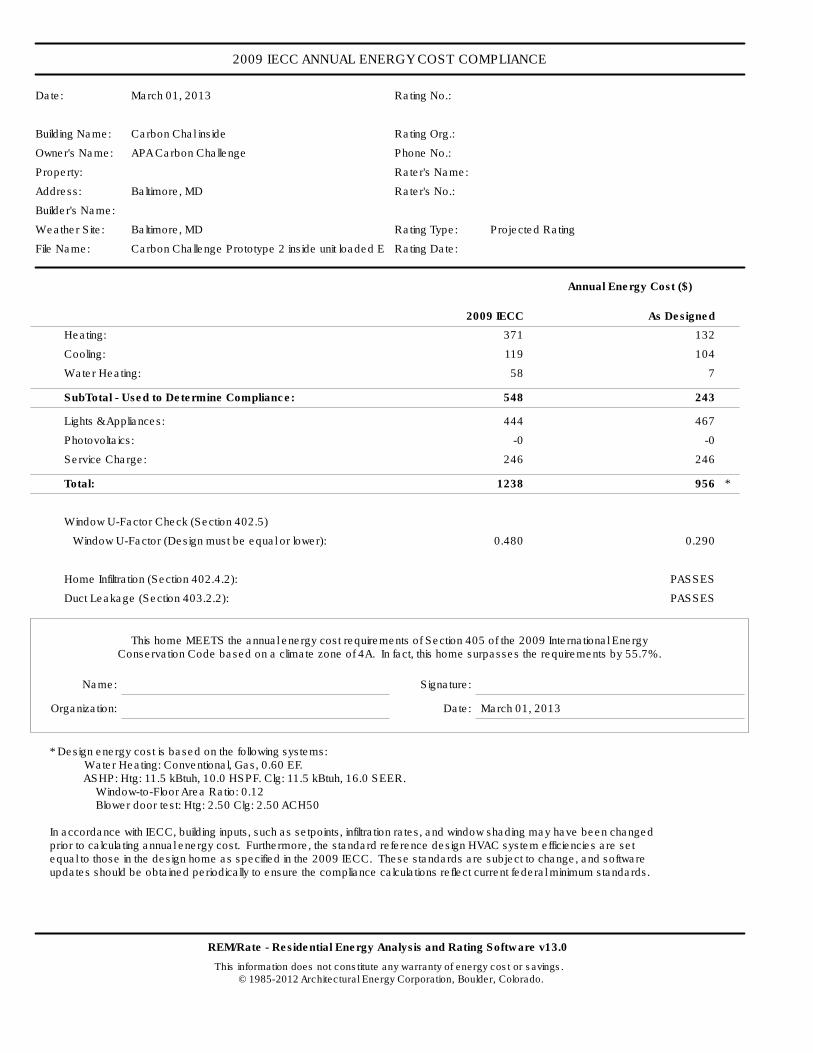
2009 IECC ANNUAL ENERGY COST COMPLIANCE
Date: March 01, 2013 Rating No.:
Building Name: Carbon Chal inside Rating Org.:
Owner's Name: APA Carbon Challenge Phone No.:
Property: Rater's Name:
Address: Baltimore, MD Rater's No.:
Builder's Name:
Weather Site: Baltimore, MD Rating Type: Projected Rating
File Name: Carbon Challenge Prototype 2 inside unit loaded ERV.blgRating Date:
REM/Rate - Residential Energy Analysis and Rating Software v13.0
This information does not constitute any warranty of energy cost or savings. © 1985-2012 Architectural Energy Corporation, Boulder, Colorado.
Annual Energy Cost ($)
2009 IECC As Designed
Heating: 371 132
Cooling: 119 104
Water Heating: 58 7
SubTotal - Used to Determine Compliance: 548 243
Lights & Appliances: 444 467
Photovoltaics: -0 -0
Service Charge: 246 246
Total: 1238 956 *
Window U-Factor Check (Section 402.5)
Window U-Factor (Design must be equal or lower): 0.480 0.290
Home Infiltration (Section 402.4.2): PASSES
Duct Leakage (Section 403.2.2): PASSES
This home MEETS the annual energy cost requirements of Section 405 of the 2009 International EnergyConservation Code based on a climate zone of 4A. In fact, this home surpasses the requirements by 55.7%.
Name: Signature:
Organization: Date: March 01, 2013
* Design energy cost is based on the following systems: Water Heating: Conventional, Gas, 0.60 EF. ASHP: Htg: 11.5 kBtuh, 10.0 HSPF. Clg: 11.5 kBtuh, 16.0 SEER. Window-to-Floor Area Ratio: 0.12 Blower door test: Htg: 2.50 Clg: 2.50 ACH50
In accordance with IECC, building inputs, such as setpoints, infiltration rates, and window shading may have been changed prior to calculating annual energy cost. Furthermore, the standard reference design HVAC system efficiencies are set equal to those in the design home as specified in the 2009 IECC. These standards are subject to change, and software updates should be obtained periodically to ensure the compliance calculations reflect current federal minimum standards.
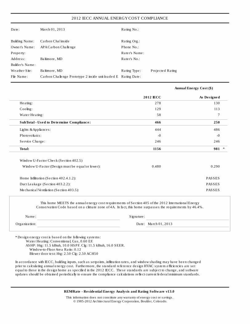
2012 IECC ANNUAL ENERGY COST COMPLIANCE
Date: March 01, 2013 Rating No.:
Building Name: Carbon Chal inside Rating Org.:
Owner's Name: APA Carbon Challenge Phone No.:
Property: Rater's Name:
Address: Baltimore, MD Rater's No.:
Builder's Name:
Weather Site: Baltimore, MD Rating Type: Projected Rating
File Name: Carbon Challenge Prototype 2 inside unit loaded ERV.blgRating Date:
REM/Rate - Residential Energy Analysis and Rating Software v13.0
This information does not constitute any warranty of energy cost or savings. © 1985-2012 Architectural Energy Corporation, Boulder, Colorado.
Annual Energy Cost ($)
2012 IECC As Designed
Heating: 278 130
Cooling: 129 113
Water Heating: 58 7
SubTotal - Used to Determine Compliance: 466 250
Lights & Appliances: 444 486
Photovoltaics: -0 -0
Service Charge: 246 246
Total: 1156 981 *
Window U-Factor Check (Section 402.5)
Window U-Factor (Design must be equal or lower): 0.480 0.290
Home Infiltration (Section 402.4.1.2): PASSES
Duct Leakage (Section 403.2.2): PASSES
Mechanical Ventilation (Section 403.5): PASSES
This home MEETS the annual energy cost requirements of Section 405 of the 2012 International EnergyConservation Code based on a climate zone of 4A. In fact, this home surpasses the requirements by 46.4%.
Name: Signature:
Organization: Date: March 01, 2013
* Design energy cost is based on the following systems: Water Heating: Conventional, Gas, 0.60 EF. ASHP: Htg: 11.5 kBtuh, 10.0 HSPF. Clg: 11.5 kBtuh, 16.0 SEER. Window-to-Floor Area Ratio: 0.12 Blower door test: Htg: 2.50 Clg: 2.50 ACH50
In accordance with IECC, building inputs, such as setpoints, infiltration rates, and window shading may have been changed prior to calculating annual energy cost. Furthermore, the standard reference design HVAC system efficiencies are set equal to those in the design home as specified in the 2012 IECC. These standards are subject to change, and software updates should be obtained periodically to ensure the compliance calculations reflect current federal minimum standards.

2012 IECC ANNUAL ENERGY COST COMPLIANCE
Carbon Chal inside Page 2
REM/Rate - Residential Energy Analysis and Rating Software v13.0
This information does not constitute any warranty of energy cost or savings. © 1985-2012 Architectural Energy Corporation, Boulder, Colorado.
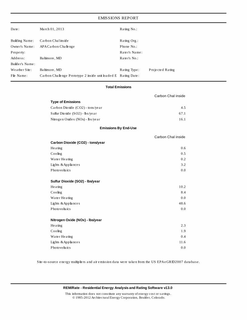
EMISSIONS REPORT
Date: March 01, 2013 Rating No.:
Building Name: Carbon Chal inside Rating Org.:
Owner's Name: APA Carbon Challenge Phone No.:
Property: Rater's Name:
Address: Baltimore, MD Rater's No.:
Builder's Name:
Weather Site: Baltimore, MD Rating Type: Projected Rating
File Name: Carbon Challenge Prototype 2 inside unit loaded ERV.blgRating Date:
REM/Rate - Residential Energy Analysis and Rating Software v13.0
This information does not constitute any warranty of energy cost or savings. © 1985-2012 Architectural Energy Corporation, Boulder, Colorado.
Total Emissions
Carbon Chal inside
Type of Emissions
Carbon Dioxide (CO2) - tons/year 4.5
Sulfur Dioxide (SO2) - lbs/year 67.1
Nitrogen Oxides (NOx) - lbs/year 16.1
Emissions By End-Use
Carbon Chal inside
Carbon Dioxide (CO2) - tons/year
Heating 0.6
Cooling 0.5
Water Heating 0.2
Lights & Appliances 3.2
Photovoltaics 0.0
Sulfur Dioxide (SO2) - lbs/year
Heating 10.2
Cooling 8.4
Water Heating 0.0
Lights & Appliances 48.6
Photovoltaics 0.0
Nitrogen Oxide (NOx) - lbs/year
Heating 2.3
Cooling 1.9
Water Heating 0.4
Lights & Appliances 11.6
Photovoltaics 0.0
Site-to-source energy multipliers and air emission data were taken from the US EPA eGRID2007 database.
Appendix 2
GREEN RATING SYSTEM REPORTS
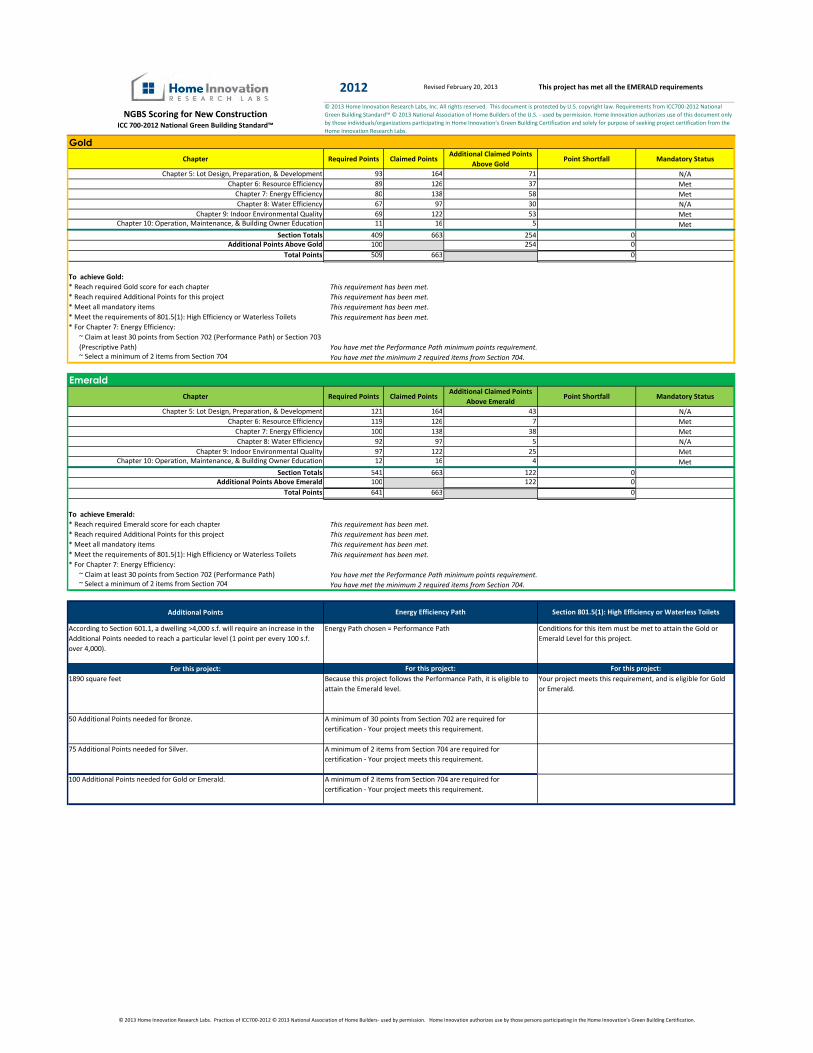
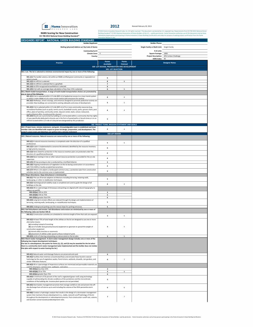
2012
NGBS Scoring for New ConstructionICC 700-2012 National Green Building Standard™
Revised February 20, 2013 This project has met all the EMERALD requirements
© 2013 Home Innovation Research Labs, Inc. All rights reserved. This document is protected by U.S. copyright law. Requirements from ICC700-2012 National
Green Building Standard™ © 2013 National Association of Home Builders of the U.S. - used by permission. Home Innovation authorizes use of this document only
by those individuals/organizations participating in Home Innovation's Green Building Certification and solely for purpose of seeking project certification from the
Home Innovation Research Labs.
Bronze
Chapter Required Points Claimed PointsAdditional Claimed Points
Above GoldPoint Shortfall Mandatory Status
Chapter 5: Lot Design, Preparation, & Development 93 164 71 N/A
Chapter 6: Resource Efficiency 89 126 37 Met
Chapter 7: Energy Efficiency 80 138 58 Met
Chapter 8: Water Efficiency 67 97 30 N/A
Chapter 9: Indoor Environmental Quality 69 122 53 Met
Chapter 10: Operation, Maintenance, & Building Owner Education 11 16 5 Met
Section Totals 409 663 254 0
Additional Points Above Gold 100 254 0
Total Points 509 663 0
* Reach required Gold score for each chapter
* Reach required Additional Points for this project
* Meet all mandatory items
* Meet the requirements of 801.5(1): High Efficiency or Waterless Toilets
* For Chapter 7: Energy Efficiency:
~ Claim at least 30 points from Section 702 (Performance Path) or Section 703
(Prescriptive Path)
~ Select a minimum of 2 items from Section 704
Chapter Required Points Claimed PointsAdditional Claimed Points
Above EmeraldPoint Shortfall Mandatory Status
Chapter 5: Lot Design, Preparation, & Development 121 164 43 N/A
Chapter 6: Resource Efficiency 119 126 7 Met
Chapter 7: Energy Efficiency 100 138 38 Met
Chapter 8: Water Efficiency 92 97 5 N/A
Chapter 9: Indoor Environmental Quality 97 122 25 Met
Chapter 10: Operation, Maintenance, & Building Owner Education 12 16 4 Met
Section Totals 541 663 122 0
Additional Points Above Emerald 100 122 0
Total Points 641 663 0
* Reach required Emerald score for each chapter
* Reach required Additional Points for this project
* Meet all mandatory items
* Meet the requirements of 801.5(1): High Efficiency or Waterless Toilets
* For Chapter 7: Energy Efficiency:
~ Claim at least 30 points from Section 702 (Performance Path)
~ Select a minimum of 2 items from Section 704
Additional Points
According to Section 601.1, a dwelling >4,000 s.f. will require an increase in the
Additional Points needed to reach a particular level (1 point per every 100 s.f.
over 4,000).
For this project:
1890 square feet
50 Additional Points needed for Bronze.
75 Additional Points needed for Silver.
100 Additional Points needed for Gold or Emerald.
For this project: For this project:
Because this project follows the Performance Path, it is eligible to
attain the Emerald level.
Your project meets this requirement, and is eligible for Gold
or Emerald.
A minimum of 30 points from Section 702 are required for
certification - Your project meets this requirement.
Energy Path chosen = Performance Path Conditions for this item must be met to attain the Gold or
Emerald Level for this project.
You have met the minimum 2 required items from Section 704.
Emerald
To achieve Emerald:
A minimum of 2 items from Section 704 are required for
certification - Your project meets this requirement.
Energy Efficiency Path Section 801.5(1): High Efficiency or Waterless Toilets
To achieve Gold:
This requirement has been met.
This requirement has been met.
This requirement has been met.
This requirement has been met.
This requirement has been met.
This requirement has been met.
This requirement has been met.
This requirement has been met.
You have met the Performance Path minimum points requirement.
Gold
You have met the minimum 2 required items from Section 704.
A minimum of 2 items from Section 704 are required for
certification - Your project meets this requirement.
You have met the Performance Path minimum points requirement.
© 2013 Home Innovation Research Labs. Practices of ICC700-2012 © 2013 National Association of Home Builders- used by permission. Home Innovation authorizes use by those persons participating in the Home Innovation’s Green Building Certification.
Revised February 20, 2013
2195
NGBS Scoring for New ConstructionICC 700-2012 National Green Building Standard™
Builder/Applicant: Builder Phone:
Mailing (physical) Address w/ Zip Code of Home: Single-Family or Multi-Unit: Single-Family
Community/Lot #: # of units:
Climate Zone: Square Footage: 1890
County: Project Description: APA Carbon Challenge
HERS Index: 40
PracticePoints
Available
Points
Claimed
501.1 Lot. The lot is selected to minimize environmental impact by one or more of the following:
501.1(1) The builder selects a lot within an NGBS certified green community or equivalent on
which to build.6
501.1(2) An infill lot is selected. 8 8
501.1(3) An infill lot is selected that is a greyfield. 7
501.1(4) An EPA-recognized brownfield lot is selected. 9
501.1(5) A lot with an average slope calculation of less than 15% is selected. 9 9
501.2 Multi-modal transportation. A range of multi-modal transportation choices are promoted by
one or more of the following:
501.2(1) A lot is selected within 1/2 mile (805 m) of pedestrian access to a mass transit system
or within 5 miles (8046 m) of a mass transit station with provisions for parking.4 4
501.2(2) Walkways, street crossings, and entrances designed to promote pedestrian activity are
provided. New buildings are connected to existing sidewalks and areas of development. 5 5
501.2(3) A lot is selected within 1/2 mile (805 m) of 6 or more community resources [e.g.,
recreational facilities (such as pools, tennis courts, basketball courts), parks, grocery store, post
office, place of worship, community center, daycare center, bank, school, restaurant,
medical/dental office, laundromat/dry cleaner].
4 4
501.2(4) Bicycle use is promoted by building on a lot located within a community that has rights-
of-way specifically dedicated to bicycle use in the form of paved paths or bicycle lanes or on an
infill lot located within 1/2 mile of a bicycle lane designated by the jurisdiction.5
502.1 Project team, mission statement, and goals. A knowledgeable team is established and team
member roles are identified with respect to green lot design, preparation, and development. The
project’s green goals and objectives are written into a mission statement.
4 4
503.1 Natural resources. Natural resources are conserved by one or more of the following:
503.1(1) A natural resources inventory is completed under the direction of a qualified
professional.5 5
503.1(2) A plan is implemented to conserve the elements identified by the resource inventory
as high-priority resources.6
503.1(3) Items listed for protection in the resource inventory plan are protected under the
direction of a qualified professional.4
503.1(4) Basic training in tree or other natural resource protection is provided for the on-site
supervisor.4
503.1(5) All tree pruning on-site is conducted by a Certified Arborist. 3
503.1(6) Ongoing maintenance of vegetation on the lot during construction is in accordance
with TCIA A300 or locally accepted best practices.4
503.1(7) Where a lot adjoins a landscaped common area, a protection plan from construction
activities next to the common area is implemented.5
503.2 Slope disturbance. Slope disturbance is minimized by:
503.2(1) The use of terrain adaptive architecture including terracing, retaining walls,
landscaping, or other re-stabilization techniques.5
503.2(2) Hydrological/soil stability study is completed and used to guide the design of all
buildings on the site.4 4
503.2(3) All or a percentage of driveways and parking are aligned with natural topography to
reduce cut and fill.503.2(3)(a) 10% to 25% 3
503.2(3)(b) 25% to 75% 4
503.2(3)(c) greater than75% 6
503.2(4) Long-term erosion effects are reduced through the design and implementation of
terracing, retaining walls, landscaping, or restabilization techniques. 5
503.2(5) Underground parking uses the natural slope for parking entrances. 5
503.3 Soil disturbance and erosion. Soil disturbance and erosion are minimized by one or more of
the following: (also see Section 504.3)
503.3(1) Construction activities are scheduled to minimize length of time that soils are exposed.5 5
503.3(2) At least 75% of total length of the utilities on the lot are designed to use one or more
alternative means:
(a) tunneling instead of trenching
(b) use of smaller (low ground pressure) equipment or geomats to spread the weight of
construction equipment
(c) shared utility trenches or easements
(d) placement of utilities under paved surfaces instead of yards
5 5
503.3(3) Limits of clearing and grading are demarcated on the lot plan. 5 5
503.4 Storm water management. A storm water management design includes one or more of the
following low-impact development techniques:
(For lots in a development, the points for items (1), (2), and (3) may be awarded for the lot when
there is a community storm water management plan implemented and the builder does not violate
that plan with respect to water leaving the lot.)
503.4(1) Natural water and drainage features are preserved and used. 6
503.4(2) Facilities that minimize concentrated flows and simulate flows found in natural
hydrology by the use of vegetative swales, french drains, wetlands, drywells, rain gardens, and
similar infiltration features.
6 7
503.4(3) All or a percentage of impervious surfaces are minimized and permeable materials are
used for driveways, parking areas, walkways, and patios.503.4(3)(a) less than 25% 2
503.4(3)(b) 25 to 75% 4 4
503.4(3)(c) greater than 75% 6
503.4(4) A minimum of 50 percent of the roof is vegetated (green roof) using technology
capable of withstanding the climate conditions of the jurisdiction and the microclimate
conditions of the building site. Invasive plant species are not permitted.5
503.4(5) Stormwater management practices that manage rainfall on-site and prevent the off-
site discharge from all storms up to and including the volume of the 95th percentile storm
event.
6 6
503.4(6) Conduct a hydrologic analysis that results in the design of a stormwater management
system that maintains the pre-development (i.e., stable, natural) runoff hydrology of the lot
throughout the development or redevelopment process. Post-construction runoff rate, volume,
and duration cannot exceed predevelopment rates.
7 7
© 2013 Home Innovation Research Labs, Inc. All rights reserved. This document is protected by U.S. copyright law. Requirements from ICC700-2012 National Green
Building Standard™ © 2013 National Association of Home Builders of the U.S. - used by permission. Home Innovation authorizes use of this document only by those
individuals/organizations participating in Home Innovation's Green Building Certification and solely for purpose of seeking project certification from the Home
Innovation Research Labs.
DESIGNERS REPORT - NATIONAL GREEN BUILDING STANDARD
4
500 LOT DESIGN, PREPARATION AND DEVELOPMENT
501 LOT SELECTION
502 PROJECT TEAM, MISSION STATEMENT AND GOALS
503 LOT DESIGN
Designer Notes
2012
© 2013 Home Innovation Research Labs. Practices of ICC700-2012 © 2013 National Association of Home Builders- used by permission. Home Innovation authorizes use by those persons participating in the Home Innovation’s Green Building Certification.
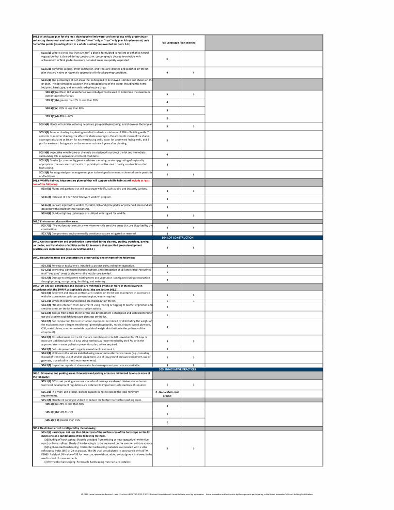
503.5 A landscape plan for the lot is developed to limit water and energy use while preserving or
enhancing the natural environment. (Where "front" only or "rear" only plan is implemented, only
half of the points [rounding down to a whole number] are awarded for items 1-6)
503.5(1) Where a lot is less than 50% turf, a plan is formulated to restore or enhance natural
vegetation that is cleared during construction. Landscaping is phased to coincide with
achievement of final grades to ensure denuded areas are quickly vegetated. 6
503.5(2) Turf grass species, other vegetation, and trees are selected and specified on the lot
plan that are native or regionally appropriate for local growing conditions. 4 4
503.5(3) The percentage of turf areas that is designed to be mowed is limited and shown on the
lot plan. The percentage is based on the landscaped area of the lot not including the home
footprint, hardscape, and any undisturbed natural areas.
503.5(3)(a) 0% or EPA WaterSense Water Budget Tool is used to determine the maximum
percentage of turf areas5 5
503.5(3)(b) greater than 0% to less than 20%4
503.5(3)(c) 20% to less than 40%3
503.5(3)(d) 40% to 60%2
503.5(4) Plants with similar watering needs are grouped (hydrozoning) and shown on the lot plan.5 5
503.5(5) Summer shading by planting installed to shade a minimum of 30% of building walls. To
conform to summer shading, the effective shade coverage is the arithmetic mean of the shade
coverage calculated at 10 am for eastward facing walls, noon for southward facing walls, and 3
pm for westward facing walls on the summer solstice 5 years after planting.5
503.5(6) Vegetative wind breaks or channels are designed to protect the lot and immediate
surrounding lots as appropriate for local conditions.4
503.5(7) On-site (or community generated) tree trimmings or stump grinding of regionally
appropriate trees are used on the site to provide protective mulch during construction or for
landscaping.
3
503.5(8) An integrated pest management plan is developed to minimize chemical use in pesticides
and fertilizers.4 4
503.6 Wildlife habitat. Measures are planned that will support wildlife habitat and include at least
two of the following:
503.6(1) Plants and gardens that will encourage wildlife, such as bird and butterfly gardens.3 3
503.6(2) Inclusion of a certified "backyard wildlife" program.3
503.6(3) Lots are adjacent to wildlife corridors, fish and game parks, or preserved areas and are
designed with regard for this relationship.3
503.6(4) Outdoor lighting techniques are utilized with regard for wildlife.3 3
503.7 Environmentally sensitive areas.
503.7(1) The lot does not contain any environmentally sensitive areas that are disturbed by the
construction.4 4
503.7(2) Compromised environmentally sensitive areas are mitigated or restored. 4
504.1 On-site supervision and coordination is provided during clearing, grading, trenching, paving
on the lot, and installation of utilities on the lot to ensure that specified green development
practices are implemented. (also see Section 503.3 ) 4 4
504.2 Designated trees and vegetation are preserved by one or more of the following:
504.2(1) Fencing or equivalent is installed to protect trees and other vegetation. 3
504.2(2) Trenching, significant changes in grade, and compaction of soil and critical root zones
in all "tree save" areas as shown on the lot plan are avoided.5
504.2(3) Damage to designated existing trees and vegetation is mitigated during construction
through pruning, root pruning, fertilizing, and watering.4
504.3 On-site soil disturbance and erosion are minimized by one or more of the following in
accordance with the SWPPP or applicable plan: (also see Section 503.3)
504.3(1) Sediment and erosion controls are installed on the lot and maintained in accordance
with the storm water pollution prevention plan, where required.5 5
504.3(2) Limits of clearing and grading are staked out on the lot. 5 5
504.3(3) "No disturbance" zones are created using fencing or flagging to protect vegetation and
sensitive areas on the lot from construction activity.5
504.3(4) Topsoil from either the lot or the site development is stockpiled and stabilized for later
use and used to establish landscape plantings on the lot.5
504.3(5) Soil compaction from construction equipment is reduced by distributing the weight of
the equipment over a larger area (laying lightweight geogrids, mulch, chipped wood, plywood,
OSB, metal plates, or other materials capable of weight distribution in the pathway of the
equipment).
4
504.3(6) Disturbed areas on the lot that are complete or to be left unworked for 21 days or
more are stabilized within 14 days using methods as recommended by the EPA, or in the
approved storm water pollution prevention plan, where required.
3 3
504.3(7) Soil is improved with organic amendments and mulch. 3
504.3(8) Utilities on the lot are installed using one or more alternative means (e.g., tunneling
instead of trenching, use of smaller equipment, use of low ground pressure equipment, use of
geomats, shared utility trenches or easements).
5 5
504.3(9) Inspection reports of storm water best management practices are available. 3 3
505.1 Driveways and parking areas. Driveways and parking areas are minimized by one or more of
the following:
505.1(1) Off-street parking areas are shared or driveways are shared. Waivers or variances
from local development regulations are obtained to implement such practices, if required. 5 5
505.1(2) In a multi-unit project, parking capacity is not to exceed the local minimum
requirements.
0 - Not a Multi-Unit
project
505.1(3) Structured parking is utilized to reduce the footprint of surface parking areas.
505.1(3)(a) 25% to less than 50%4
505.1(3)(b) 50% to 75%5
505.1(3)( c) greater than 75%6
505.2 Heat island effect is mitigated by the following:
505.2(1) Hardscape: Not less than 50 percent of the surface area of the hardscape on the lot
meets one or a combination of the following methods.
(a) Shading of hardscaping: Shade is provided from existing or new vegetation (within five
years) or from trellises. Shade of hardscaping is to be measured on the summer solstice at noon.
(b) Light-colored hardscaping: Horizontal hardscaping materials are installed with a solar
reflectance index (SRI) of 29 or greater. The SRI shall be calculated in accordance with ASTM
E1980. A default SRI value of 35 for new concrete without added color pigment is allowed to be
used instead of measurements.
(c) Permeable hardscaping: Permeable hardscaping materials are installed.
5 5
505 INNOVATIVE PRACTICES
504 LOT CONSTRUCTION
Full Landscape Plan selected
© 2013 Home Innovation Research Labs. Practices of ICC700-2012 © 2013 National Association of Home Builders- used by permission. Home Innovation authorizes use by those persons participating in the Home Innovation’s Green Building Certification.
505.2(2) Roofs: Not less than 75% of the exposed surface of the roof meets one or a
combination of the following methods.
(a) Minimum initial SRI of 78 for a low-sloped roof (a slope less than or equal to 2:12) and a
minimum initial (SRI) of 29 for a steep-sloped roof (a slope of more than 2:12). The SRI shall be
calculated in accordance with ASTM E1980. Roof products shall be labeled and certified.
(b) Roof is vegetated using technology capable of withstanding the climate conditions of the
jurisdiction and the microclimate conditions of the building site. Invasive plant species are not
permitted.
5 5
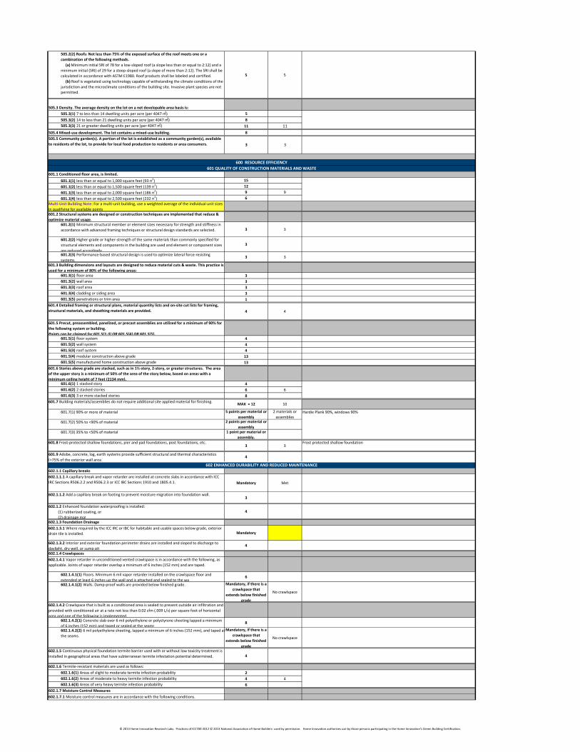
505.3 Density. The average density on the lot on a net developable area basis is:
505.3(1) 7 to less than 14 dwelling units per acre (per 4047 m2) 5
505.3(2) 14 to less than 21 dwelling units per acre (per 4047 m2) 8
505.3(3) 21 or greater dwelling units per acre (per 4047 m2) 11 11
505.4 Mixed-use development. The lot contains a mixed-use building. 8
505.5 Community garden(s). A portion of the lot is established as a community garden(s), available
to residents of the lot, to provide for local food production to residents or area consumers. 3 3
601.1 Conditioned floor area, is limited.
601.1(1) less than or equal to 1,000 square feet (93 m2) 15
601.1(2) less than or equal to 1,500 square feet (139 m2) 12
601.1(3) less than or equal to 2,000 square feet (186 m2) 9 9
601.1(4) less than or equal to 2,500 square feet (232 m2) 6
Multi-Unit Building Note: For a multi-unit building, use a weighted average of the individual unit sizes
in qualifying for available points.
601.2 Structural systems are designed or construction techniques are implemented that reduce &
optimize material usage.
601.2(1) Minimum structural member or element sizes necessary for strength and stiffness in
accordance with advanced framing techniques or structural design standards are selected. 3 3
601.2(2) Higher-grade or higher-strength of the same materials than commonly specified for
structural elements and components in the building are used and element or component sizes
are reduced accordingly.
3
601.2(3) Performance-based structural design is used to optimize lateral force-resisting
systems.3 3
601.3 Building dimensions and layouts are designed to reduce material cuts & waste. This practice is
used for a minimum of 80% of the following areas:
601.3(1) floor area 3
601.3(2) wall area 3
601.3(3) roof area 3
601.3(4) cladding or siding area 3
601.3(5) penetrations or trim area 1
601.4 Detailed framing or structural plans, material quantity lists and on-site cut lists for framing,
structural materials, and sheathing materials are provided. 4 4
601.5 Precut, preassembled, panelized, or precast assemblies are utilized for a minimum of 90% for
the following system or building.
Points can be claimed for 601.5(1-3) OR 601.5(4) OR 601.5(5).601.5(1) floor system 4
601.5(2) wall system 4
601.5(3) roof system 4
601.5(4) modular construction above grade 13
601.5(5) manufactured home construction above grade 13
601.6 Stories above grade are stacked, such as in 1½-story, 2-story, or greater structures. The area
of the upper story is a minimum of 50% of the area of the story below, based on areas with a
minimum ceiling height of 7 feet (2134 mm).601.6(1) 1 stacked story 4
601.6(2) 2 stacked stories 6 6
601.6(3) 3 or more stacked stories 8
601.7 Building materials/assemblies do not require additional site applied material for finishing. MAX = 12 10
601.7(1) 90% or more of material 5 points per material or
assembly
2 materials or
assemblies
601.7(2) 50% to <90% of material 2 points per material or
assembly
601.7(3) 35% to <50% of material 1 point per material or
assembly.
601.8 Frost-protected shallow foundations, pier and pad foundations, post foundations, etc.3 3
601.9 Adobe, concrete, log, earth systems provide sufficient structural and thermal characteristics
(>75% of the exterior wall area )4
602.1.1 Capillary breaks
602.1.1.1 A capillary break and vapor retarder are installed at concrete slabs in accordance with ICC
IRC Sections R506.2.2 and R506.2.3 or ICC IBC Sections 1910 and 1805.4.1. Mandatory Met
602.1.1.2 Add a capillary break on footing to prevent moisture migration into foundation wall.3
602.1.2 Enhanced foundation waterproofing is installed:
(1) rubberized coating, or
(2) drainage mat
4
602.1.3 Foundation Drainage
602.1.3.1 Where required by the ICC IRC or IBC for habitable and usable spaces below grade, exterior
drain tile is installed. Mandatory
602.1.3.2 Interior and exterior foundation perimeter drains are installed and sloped to discharge to
daylight, dry well, or sump pit.4
602.1.4 Crawlspaces
602.1.4.1 Vapor retarder in unconditioned vented crawlspace is in accordance with the following, as
applicable. Joints of vapor retarder overlap a minimum of 6 inches (152 mm) and are taped.
602.1.4.1(1) Floors. Minimum 6 mil vapor retarder installed on the crawlspace floor and
extended at least 6 inches up the wall and is attached and sealed to the wall.6
602.1.4.1(2) Walls. Damp-proof walls are provided below finished grade. Mandatory, if there is a
crawlspace that
extends below finished
grade
No crawlspace
602.1.4.2 Crawlspace that is built as a conditioned area is sealed to prevent outside air infiltration and
provided with conditioned air at a rate not less than 0.02 cfm (.009 L/s) per square foot of horizontal
area and one of the following is implemented:602.1.4.2(1) Concrete slab over 6 mil polyethylene or polystyrene sheeting lapped a minimum
of 6 inches (152 mm) and taped or sealed at the seams.8
602.1.4.2(2) 6 mil polyethylene sheeting, lapped a minimum of 6 inches (152 mm), and taped at
the seams.
Mandatory, if there is a
crawlspace that
extends below finished
grade
No crawlspace
602.1.5 Continuous physical foundation termite barrier used with or without low toxicity treatment is
installed in geographical areas that have subterranean termite infestation potential determined. 4
602.1.6 Termite-resistant materials are used as follows:
602.1.6(1) Areas of slight to moderate termite infestion probability 2
602.1.6(2) Areas of moderate to heavy termite infestion probability 4 4
602.1.6(3) Areas of very heavy termite infestion probability 6
602.1.7 Moisture Control Measures
602.1.7.1 Moisture control measures are in accordance with the following conditions.
Frost protected shallow foundation
Hardie Plank 90%, windows 90%
600 RESOURCE EFFICIENCY
601 QUALITY OF CONSTRUCTION MATERIALS AND WASTE
602 ENHANCED DURABILITY AND REDUCED MAINTENANCE
© 2013 Home Innovation Research Labs. Practices of ICC700-2012 © 2013 National Association of Home Builders- used by permission. Home Innovation authorizes use by those persons participating in the Home Innovation’s Green Building Certification.
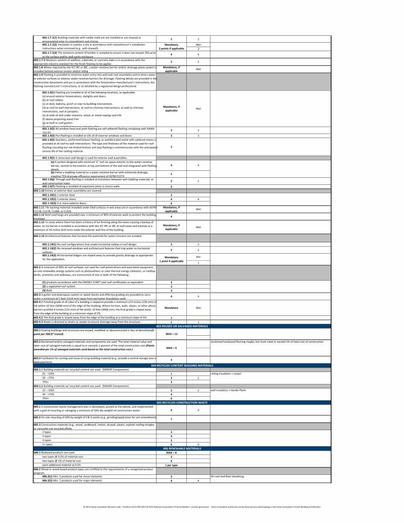
602.1.7.1(1) Building materials with visible mold are not installed or are cleaned or
encapsulated prior to concealment and closing.2 2
Met
2
602.1.7.1(3) The moisture content of lumber is sampled to ensure it does not exceed 19% prior
to the surface and/or wall cavity enclosure.4 4
602.1.7.2 Moisture content of subfloor, substrate, or concrete slabs is in accordance with the
appropriate industry standard for the finish flooring to be applied.2 2
602.1.8 Where required by the ICC IRC or IBC, a water-resistive barrier and/or drainage plane system is
installed behind exterior veneer and/or siding.
Mandatory, if
applicableMet
602.1.9 Flashing is provided to minimize water entry into wall and roof assemblies and to direct water
to exterior surfaces or exterior water-resistive barriers for drainage. Flashing details are provided in the
construction documents and are in accordance with the fenestration manufacturer’s instructions, the
flashing manufacturer’s instructions, or as detailed by a registered design professional.
602.1.9(1) Flashing are installed at all of the following locations, as applicable:
(a) around exterior fenestrations, skylights and doors
(b) at roof valleys
(c) at deck, balcony, porch or stair to building intersections
(d) at roof-to-wall intersections, at roof-to-chimney intersections, at wall-to-chimney
intersections, and at parapets.
(e) at ends of and under masonry, wood, or metal copings and sills
(f) above projecting wood trim
(g) at built-in roof gutters
(h) drip edge is installed at eaves and rake edges.
Mandatory, if
applicableMet
602.1.9(2) All window head and jamb flashing are self-adhered flashing complying with AAMA
711-07.2 2
602.1.9(3) Pan flashing is installed at sills of all exterior windows and doors. 3 3
602.1.9(4) Seamless, preformed kickout flashing, or prefabricated metal with soldered seams is
provided at all roof-to-wall intersections. The type and thickness of the material used for roof
flashing including but not limited kickout and step flashing is commensurate with the anticipated
service life of the roofing material.
3
602.1.9(5) A rainscreen wall design is used for exterior wall assemblies.
(a) A system designed with minimum ¼” inch air space exterior to the water-resistive
barrier, vented to the exterior at top and bottom of the wall and integrated with flashing
details.
4 4
(b) Either a cladding material or a water-resistive barrier with enhanced drainage,
meeting 75% drainage efficiency requirement of ASTM E2273.2
602.1.9(6) Through wall flashing is installed at transitions between wall cladding materials, or
wall construction types.2 2
602.1.9(7) Flashing is installed at expansion joints in stucco walls. 2
602.1.10 Entries at exterior door assemblies are covered
602.1.10(1) 1 exterior door 2
602.1.10(2) 2 exterior doors 4 4
602.1.10(3) 3 or more exterior doors 6
602.1.11 Tile backing materials installed under tiled surfaces in wet areas are in accordance with ASTM
C1178, C1278, C1288, or C1325.
Mandatory, if
applicableMet
602.1.12 Roof overhangs are provided over a minimum of 90% of exterior walls to protect the building
envelope.4
602.1.13 In areas where there has been a history of ice forming along the eaves causing a backup of
water, an ice barrier is installed in accordance with the ICC IRC or IBC at roof eaves and extends at a
minimum of 24 inches (610 mm) inside the exterior wall line of the building.
Mandatory, if
applicableMet
602.1.14 Architectural features that increase the potential for water intrusion are avoided.
602.1.14(1) No roof configurations that create horizontal valleys in roof design. 2 2
602.1.14(2) No recessed windows and architectural features that trap water on horizontal
surfaces.2 2
Met
1
602.2 A minimum of 90% of roof surfaces, not used for roof penetrations and associated equipment,
on-site renewable energy systems such as photovoltaics or solar thermal energy collectors, or rooftop
decks, amenities and walkways, are constructed of one or both of the following:
(1) products accordance with the ENERGY STAR® cool roof certification or equivalent 3
(2) a vegetated roof system 3
(3) Both 3
602.3 A gutter and downspout system or splash blocks and effective grading are provided to carry
water a minimum of 5 feet (1524 mm) away from perimeter foundation walls.4 4
602.4.1 Finished grade at all sides of a building is sloped to provide a minimum of 6 inches (150 mm) of
fall within 10 feet (3048 mm) of the edge of the building. Where lot lines, walls, slopes, or other physical
barriers prohibit 6 inches (152 mm) of fall within 10 feet (3048 mm), the final grade is sloped away
from the edge of the building at a minimum slope of 2%.
Mandatory Met
602.4.2 The final grade is sloped away from the edge of the building at a minimum slope of 5%. 1
602.4.3 Water is directed to drains or swales to ensure drainage away from the structure. 1 1
603.3 Facilitation for sorting and reuse of scrap building material (e.g., provide a central storage area or
dedicated bins).4
604.1.1 Building materials w/ recycled content are used. (MINOR Components)
25 - <50% 1
50 - <75% 2 2
75%+ 3
604.1.2 Building materials w/ recycled content are used. (MAJOR Components)
25 - <50% 2 2
50 - <75% 4
75%+ 6
605.1 A construction waste management plan is developed, posted at the jobsite, and implemented
with a goal of recycling or salvaging a minimum of 50% (by weight) of construction waste. 6 6
605.2 On-site recycling of 50% by weight of C& D waste (e.g., grinding/application for soil amendment).7
605.3 Construction materials (e.g., wood, cardboard, metals, drywall, plastic, asphalt roofing shingles,
or concrete) are recycled offsite.
2 types 3
3 types 4
4 types 5
5+ types 6 6
606.1 Biobased products are used. MAX = 8
two types @ 0.5% of material cost 3
two types @ 1% of material cost 6
each additional material at 0.5% 1 per type
606.2 Wood or wood-based product types are certified to the requirements of a recognized product
program:
606.2(1) Min. 2 products used for minor elements 3
606.2(2) Min. 2 products used for major elements 4 4
SFI roof and floor sheathing,
602.1.7.1(2) Insulation in cavities is dry in accordance with manufacturer’s installation
instructions when enclosed (e.g., with drywall).
Mandatory
2 points if applicable
603 REUSED OR SALVAGED MATERIALS
604 RECYCLED CONTENT BUILDING MATERIALS
605 RECYCLED CONSTRUCTION WASTE
606 RENEWABLE MATERIALS
Mandatory
1 point if applicable
602.1.14(3) All horizontal ledgers are sloped away to provide gravity drainage as appropriate
for the application.
wall insulation + Hardie Plank
603.1 Existing buildings and structures are reused, modified, or deconstructed in lieu of demolition. (1
point per 200 ft² reused) MAX = 12
603.2 Reclaimed and/or salvaged materials and components are used. The total material value and
labor cost of salvaged materials is equal to or exceeds 1 percent of the total construction cost. (Points
awarded per 1% of salvaged materials used based on the total construction cost.)MAX = 9
reclaimed hardwood flooring maybe, but must meet or exceed 1% of total cost of construction
ceiling insulation + carpet
© 2013 Home Innovation Research Labs. Practices of ICC700-2012 © 2013 National Association of Home Builders- used by permission. Home Innovation authorizes use by those persons participating in the Home Innovation’s Green Building Certification.
606.3 Materials used for major components are manufactured using a min. of 33% of the primary
manufacturing process energy from renewable sources, combustible waste sources, or renewable
energy credits (RECs).1 material 2
2 materials 4
3+ materials 6
607.1(1) A built-in collection space in each kitchen and an aggregation/pick-up space in a garage,
covered outdoor space, or other area for recycling containers.3
607.1(2) Compost facility provided on-site. 3 3
607.2 A minimum of one food waste disposer is installed at the primary kitchen sink. 1
608.1 Products containing fewer materials are used to achieve the same end-use requirements as
conventional products, including but not limited to:
(1) lighter, thinner brick with bed depth < 3 inches and/or brick with coring > 25%
(2) engineered wood or engineered steel products
(3) roof or floor trusses1 product 3 3
2 products 6
3+ products 9
609.1 Regional materials are used for major elements or components of the building.
1 type 2
2 types 4
3 types 6
4 types 8 8
5+ types 10
610.1 A life cycle analysis (LCA) tool is used to select environmentally preferable products or
assemblies, or an LCA is conducted on the entire building.15 points for 610.1.1
10 points max. for 610.1.2
15
610.1.1 A whole-building LCA is performed using a life cycle assessment and data compliant with ISO
14044 or other recognized standards.15 15
610.1.2 An environmentally preferable product or assembly is selected for an application based upon
the use of an LCA tool that incorporates data methods compliant with ISO 14044 or other recognized
standards that compare the environmental impact of products or assemblies.
10 points max.
for 610.1.2(1) & (2)
610.1.2(1) Two or more products with the same intended use are compared based on LCA and
the product with at least a 15% average improvement is selected. Number of points awarded is
based on the number of environmental impact measures compared.
MAX = 10
Points per Table 610.1.2(1)
# of comparions with 4 impact measures:
# of comparions with 5 impact measures:
610.1.2(2) Building assembly LCA. A building assembly with improved environmental impact
measures compared to an alternative assembly of the same function is selected.MAX = 10
Points per Table 610.1.2(2)
# of impact measures in LCA for exterior walls:
# of impact measures in LCA for roof/ceilings:
# of impact measures in LCA for interior walls or ceilings:
# of impact measures in LCA for intermediate floors:
611.1 Product manufacturer's operations and business practices include environmental management
system concepts, and the production facility is ISO 14001 certified or equivalent. The aggregate value
of building products from ISO 14001 certified or equivalent production facilities is 1% or more of the
estimated total building materials cost.
1% - <2% 1
2% - <3% 2
3% - <4% 3
4% - <5% 4
5% - <6% 5
6% - <7% 6
7% - <8% 7
8% - <9% 8
9% - <10% 9
10+% 10
611.2 One or more of the following products are used for at least 30% of the floor or wall area of the
entire dwelling unit, as applicable. Certification third-party agency is ISO Guide 65 accredited. MAX = 9
(1) 50% or more of carpet installed (by square feet) is third-party certified to NSF/ANSI 140.3
(2) 50% or more of resilient flooring installed (by square feet) is third-party certified to NSF/ANSI
332.3
(3) 50% or more of the insulation installed (by square feet) is third-party certified to EcoLogo
CCD-016.3
(4) 50% or more of interior wall coverings installed (by square feet) is third-party certified to
NSF/ANSI 342.3
(5) 50% or more of the gypsum board installed (by square feet) is third-party certified to ULE ISR
100.3
(6) 50% or more of the door leafs installed (by number of door leafs) is third-party certified to
ULE ISR 102.3
(7) 50% or more of the tile installed (by square feet) is third-party certified to ANSI A138.1
Specifications for Sustainable Ceramic Tiles, Glass Tiles and Tile Installation Materials. 3
611.3 Universal design elements. Dwelling incorporates one or more of the following universal design
elements.MAX = 9
(1) Any no-step entrance into the dwelling which is accessible from a substantially level parking
or drop-off area (no more than 2%) via an accessible path which has no individual change in
elevation or other obstruction of more than 1-1/2 inches in height, whose pitch does not exceed
1 in 12 and which provides a minimum 32-inch wide clearance into the dwelling.
3
(2) Minimum 36-inch wide accessible route from the no-step entrance into at least one visiting
room in the dwelling and into at least one full or half bathroom which has a minimum 32 inch
clear door width and a 30 inch by 48 inch clear area inside the bathroom outside the door
swing.
3
(3) Minimum 36-inch wide accessible route from the no-step entrance into at least one
bedroom which has a minimum 32 inch clear door width.3
(4) Blocking or equivalent installed in the accessible bathroom walls for future installation of
grab bars at commode and bathing fixture, if applicable.1
701.1 The building shall comply with either Section 702 or Section 703
701.1 The building shall comply with either Section 702 (Performance Path) or Section 703
(Prescriptive Path). Items listed as "mandatory" in Section 701.4 apply to both the Performance and
Prescriptive Paths. As an alternative, an ENERGY STAR® 2.0 Qualified Home or equivalent can claim
30 points from 701.1.3 and meet the Bronze level for Chapter 7.
701.1.1 Minimum Performance Path requirements. A building complying with Section 702 shall
exceed the ICC IECC by 15%, & shall include a min. of 2 practices from Sec. 704, OR meet 701.1.2 OR
701.1.3.
701.1.2 Minimum Prescriptive Path requirements. A building complying with Sec. 703 shall obtain
a minimum of 30 points from Sec. 703, & shall include a min. of 2 practices from Sec. 704.
701.1.3 Alternative Bronze Level compliance. Any ENERGY STAR Qualified Home achieves the
Bronze Level for Chapter 7.
Performance Path
OR
Prescriptive Path
OR
Alternative Bronze
Level Compliance
Performance Path
53.4% better than 2009 IECC
700 ENERGY EFFICIENCY
701 MINIMUM ENERGY EFFICIENCY REQUIREMENTS
611 INNOVATIVE PRACTICES
User must select either Performance (701.1.1) , Prescriptive (701.1.2) , or Alternative Bronze (701.1.3) compliance path.
(Choose one path only)
engineered wood
Hardie Plank, concrete for footing and slab, aggregate for slab base
608 RESOURCE-EFFICIENT MATERIALS
609 REGIONAL MATERIALS
610 LIFE CYCLE ANALYSIS
607 RECYCLING & WASTE REDUCTION
© 2013 Home Innovation Research Labs. Practices of ICC700-2012 © 2013 National Association of Home Builders- used by permission. Home Innovation authorizes use by those persons participating in the Home Innovation’s Green Building Certification.
701.1.3 Alternative Bronze Level compliance. Any ENERGY STAR 2.0 Qualified Home or
equivalent achieves the Bronze Level for Chapter 7.
If 30 points claimed for practice 701.1.3, this chapter and this project cannot achieve a level higher
than Bronze.
If points claimed for this practice, skip the following sections:
* 701.3 - Adopting Entity review
* 701.4 - Mandatory Practices
* 702 - Performance Path
* 703 - Prescriptive Path
Points can be claimed in Section 704 that count toward additional points needed for the project to
30
701.2 Emerald Level points. The Performance Path shall be used to achieve the Emerald Level.
701.3 Adopting Entity review. A review by third party shall be conducted to verify design and
compliance with Chapter 7 points. Mandatory Met
701.4 Mandatory practices.
701.4.1 HVAC systems.
701.4.1.1 Space heating/cooling sized per Manual J Mandatory Met
701.4.1.2 Radiant/hydronic heating system designed using industry-approved guidelinesMandatory
Not primary heat
source
701.4.2 Duct systems.
701.4.2.1 Ducts are air sealed with materials in conformance with UL 181A or UL 181B
specificationsMandatory
No duct system
installed
701.4.2.2 Building cavities are not used as supply ducts Mandatory No Duct System
701.4.2.3 Duct system is sized and designed in accordance with ACCA Manual D or equivalentMandatory No Duct System
701.4.3 Insulation and air sealing.
701.4.3.1 Building Thermal Envelope. The building thermal envelope is durably sealed to limit
infiltration.Mandatory Met
701.4.3.2 Air sealing and insulation. Grade 3 insulation installation is not permitted. The
compliance of the building envelope air tightness and insulation installation is demonstrated in
accordance with Section 701.4.3.2(1) or 701.4.3.2(2).
Met
3 ACH50
701.4.3.2(2) Visual inspection option. Building envelope tightness and insulation
installation are considered acceptable when the components listed below applicable to
the method of construction, are field verified.701.4.3.3 Fenestration air leakage. Windows, skylights and sliding glass doors have an air
infiltration rate of no more than 0.3 cfm per square foot (1.5 L/s/m2), and swinging doors no
more than 0.5 cfm per square foot (2.6 L/s/m2).
Mandatory Met
701.4.3.4 Recessed lighting. Recessed luminaires installed in the building thermal envelope are
sealed to limit air leakage between conditioned and unconditioned spaces. MandatoryNo Recessed
Fixtures
701.4.4 High-efficacy lighting. A minimum of 50% of the total hard-wired lighting fixtures, or the
bulbs in those fixtures, qualify as high efficacy or equivalent.Mandatory Met
701.4.5 Boiler supply piping. Boiler supply piping in unconditioned space is insulated. Mandatory N/A
702.1 Points from Section 702 (Performance Path) shall not be combined with points from Section
703 (Prescriptive Path).
702.2.1 ICC IECC analysis. Energy efficiency features are implemented to achieve energy cost
performance that meets the ICC IECC.Mandatory Met
702.2.2 A documented analysis shows performance in excess of 2009 IECC by at least one of the
following:
702.2.2(1) 15% 30
702.2.2(2) 30% 60
702.2.2(3) 40% 100 100
702.2.2(4) 50% 120
703.1 Building envelope
703.1.1 UA improvement. The total building thermal envelope UA is less than or equal to the total
UA resulting from the U-factors provided in Table 703.1.1(a). Where insulation is used to achieve
the UA improvement, the insulation installation is in accordance with Grade 1 requirements as
graded by a third-party. Total UA is documented using a RESCheck or equivalent report to verify the
baseline and the UA improvement.
5 to <10%
10% to <15%
15% to <20%
20% or greater
703.1.2 The insulation installation is graded by a third party and in accordance with Sections
703.1.2.1, 703.1.2.2, 703.1.2.3, and/or 703.1.2.4, as applicable.
Grade 1 7
Grade 2 4
703.1.3 Mass walls. More than 75% of the above-grade exterior opaque wall area of the building is
mass walls.
≥3 inch to <6 inch 5
> 6 inch 3
703.1.4 A radiant barrier with an emittance of 0.05 or less is used in the attic.1
703.1.5 Building envelope leakage. The maximum building envelope leakage rate is in accordance
with Table 703.1.5. (Also see Section 902.2.1)
Max Envelope Leakage Rate (ACH50) = 5 4
Max Envelope Leakage Rate (ACH50) = 4 7
Max Envelope Leakage Rate (ACH50) = 3 9
Max Envelope Leakage Rate (ACH50) = 2 11
Max Envelope Leakage Rate (ACH50) = 1 12
703.1.6 Fenestration
703.1.6.1 NFRC-certified (or equivalent) U-factor and SHGC of windows, exterior doors, skylights,
and tubular daylighting devices (TDDs) on an area-weighted average basis are in accordance with
Table 703.1.6.1.
Mandatory N/A
703.1.6.2 The NFRC-certified (or equivalent) U-factor and SHGC of windows, exterior doors,
skylights, and tubular daylighting devices (TDDs) are in accordance with Table 703.1.6.2(a), (b), or
(c).Table 703.1.6.2(a): Enhanced Fenestration Specifications 2
Table 703.1.6.2(b): Enhanced Fenestration Specifications 4
Table 703.1.6.2(c ): Enhanced Fenestration Specifications 5
703.2 HVAC equipment efficiency
703.2.1 Combination space heating and water heating system (combo system) is installed using
either a coil from the water heater connected to an air handler to provide heat for the building or
dwelling unit, or a space heating boiler using an indirect-fired water heater. Devices have a
combined annual efficiency of 0.80.
4
703.2.3 Heat pump heating efficiency is in accordance with Table 703.2.4. Refrigerant charge is
verified for compliance with manufacturer's instructions.
8.2 HSPF (11.5 EER) 4
9.0 HSPF (12.5 EER) 9
9.5 HSPF 12
10.0 HSPF 15
Points per
Table 703.2.2(1) or
Table 703.2.2(2) or
Table 703.2.2(3) or
Table 703.2.2(4)
703.2.2 Furnace and/or boiler efficiency is in accordance with Tables 703.2.2(1), 703.2.2(2),
703.2.2(3), 703.2.2(4).
702 PERFORMANCE PATH
703 PRESCRIPTIVE PATH
53.4% better than 2009 IECC, 43.7% better than 2012 IECC.note704.5.2.1_1
per Table 703.1.1
701.4.3.2(1) Testing option. Building envelope tightness and insulation installation is
considered acceptable when air leakage is less than seven air changes per hour (ACH)
when tested with a blower door at a pressure of 33.5 psf (50 Pa).Mandatory
© 2013 Home Innovation Research Labs. Practices of ICC700-2012 © 2013 National Association of Home Builders- used by permission. Home Innovation authorizes use by those persons participating in the Home Innovation’s Green Building Certification.
703.2.4 Cooling efficiency is in accordance with Table 703.2.4. Refrigerant charge is verified for
compliance with manufacturer's instructions.
≥ 14 SEER (11.5 EER) 1
≥ 15 SEER (12.5 EER) 1
≥ 17 SEER (12.5 EER) 2
≥ 19+ SEER (12.5 EER) 3
≥ 19+ SEER 3
703.2.5 Water source cooling and heating efficiency is ≥ 15 EER, ≥ 4.0 COP. 30
703.2.6 Ground source heat pump is installed by a Certified Geothermal Service Contractor in
accordance with Table 703.2.6.
14.1 EER 3.3 COP 22
15 EER 3.5 COP 25
16.2 EER 3.6 COP 27
24 EER 4.3 COP 35
28 EER 4.8 COP 40
703.2.7 ENERGY STAR, or equivalent, ceiling fan(s) are installed. 1
703.2.8 Whole-building or whole-dwelling unit fan(s) with insulated louvers and a sealed enclosure
is installed.3
703.2.9 In multi-unit buildings, an advanced electric and fossil fuel submetering system is installed
to monitor electricity and fossil fuel consumption for each unit.1 N/A
703.3 Duct Systems
703.3.1 All space heating is provided by a system(s) that does not include air ducts. 7
703.3.2 All space cooling is provided by a system(s) that does not include air ducts. 1
703.3.3 Ductwork is in accordance with all of the following:
(1) Building cavities are not used as return ductwork.
(2) Heating and cooling ducts and mechanical equipment are installed within the
conditioned building space.
(3) Ductwork is not installed in exterior walls.
8
703.3.4 Duct Leakage. The entire central HVAC duct system, including air handlers and register
boots, is tested by a third party for total leakage at a pressure differential of 0.1 inches w.g. (25 Pa)
and maximum air leakage is equal to or less than 6 percent of the system design flow rate.
Ductwork entirely outside the building's thermal envelope 6
Ductwork entirely inside the building’s thermal envelope 2
Ductwork inside and outside the building's thermal envelope 4
703.4 Water heating system
703.4.2 Desuperheater is installed by a qualified installer or is pre-installed in the factory.8
703.4.3 Drain-water heat recovery system is installed in multi-family units. 2 N/A
703.4.4 Indirect-fired water heater storage tanks heated from boiler systems are installed. 1
703.4.5 Solar water heater. SRCC (Solar Rating & Certification Corporation) OG 300 rated, or
equivalent, solar domestic water heating system is installed. Solar Energy Factor (SEF) as defined by
SRCC) is in accordance with Table 703.4.5.≥SEF 1.3 12
≥SEF 1.51 14
≥SEF 1.81 17
≥SEF 2.31 20
≥SEF 3.01 23
703.5 Lighting and appliances
703.5.1 Hard-wired lighting is in accordance with one of the following:
703.5.1(1) A minimum of 75% of the total hard-wired luminaires qualify as ENERGY STAR or
equivalent.3
703.5.1(1) A minimum of 95% of the total hard-wired luminaires qualify as ENERGY STAR or
equivalent.4
703.5.1(2) A minimum of 80% of the exterior lighting wattage has a minimum efficiency of 40
lumens per watt or is solar-powered.1
1890 s.f. total
floor area
703.5.3 Appliances. ENERGY STAR or equivalent appliance(s) are installed.
Refrigerator 1
Dishwasher 1
Washing machine 4
703.5.4 Induction cooktop. Induction cooktop is installed. 1
703.6 Passive solar design
703.6.1 Sun-tempered design. Building orientation, sizing of glazing, and design of overhangs are in
accordance with Sections 703.6.1(1-9).5
703.6.2 Window shading. Automated solar protection is installed to provide shading for windows.1
703.6.3 Passive cooling design features are in accordance with at least 3 from (1)-(6) below, but no
more than 4.
Exterior shading is provided on east and west windows using one or a combination of the
following:
(a) Vine-covered trellises with the vegetation separated a minimum of 1 foot (305 mm)
from face of building
(b) moveable awnings or louvers
(c) covered porches
(d) attached or detached conditioned/unconditioned enclosed space that provides full
shade of east and west windows (e.g., detached garage, shed, or building)
1
Overhangs are installed to provide shading on south-facing glazing in accordance with
Section 703.6.1(7).
Points not awarded if points are taken under Section 703.6.1
1
Windows and/or venting skylights are located to facilitate cross ventilation. 1
Solar reflective roof or radiant barrier is installed in climate zones 1, 2, or 3 and roof material
achieves a 3-year aged criteria of 0.50.1
Internal exposed thermal mass is a minimum of three inches (76 mm) in thickness. Thermal
mass consists of concrete, brick, and/or tile that are fully adhered to a masonry base or
other masonry material and is in accordance with one or a combination of the following:
(a) A minimum of 1 square foot (0.09 m2) of exposed thermal mass of floor per 3 square
feet (2.8 m2) of gross finished floor area.
(b) A minimum of 3 square feet (2.8 m2) of exposed thermal mass in interior walls or
elements per square foot (0.09 m2) of gross finished floor area.
1
Roofing material is installed with a minimum 0.75 inch (19 mm) continuous air space offset
from the roof deck from eave to ridge.1
703.6.4 Passive solar heating design. In addition to the sun-tempered design features in Section
703.6.1, all of Sections 703.6.4 (1-3) are implemented.4
704.2 Lighting
704.2.1 Occupancy sensors. Occupancy sensors are installed on indoor lights, and photo or motion
sensors are installed on outdoor lights to control lighting.25% of lighting 1
50% of lighting 2
704 ADDITIONAL PRACTICES
703.5.2 Recessed luminaires. The number of recessed luminaires that penetrate the thermal
envelope are less than 1 per 400 square feet (37.16 m2) of total conditioned floor area and are in
accordance with Section 701.4.3.4.
2
Points per
Table 703.4.1(1)(a) or
Table 703.4.1(1)(b) or
Table 703.4.1(2) or
Table 703.4.1(3) or
Table 703.4.1(4)
703.4.1 Water heater Energy Factor (EF) is in accordance with the tables in 703.4.1.
© 2013 Home Innovation Research Labs. Practices of ICC700-2012 © 2013 National Association of Home Builders- used by permission. Home Innovation authorizes use by those persons participating in the Home Innovation’s Green Building Certification.
704.2.2 TDDs and skylights. Tubular daylighting device (TDD) or a skylight with sealed, insulated,
low-E glass is installed in rooms without windows.2
704.2.3 Occupancy sensors are installed on indoor lights, and photo or motion sensors are installed
on outdoor lights to control lighting. 1
704.3 Return ducts and transfer grilles. Return ducts or transfer grilles are installed in every room
with a door. Return ducts or transfer grilles are not required for bathrooms, kitchens, closets, pantries,
and laundry rooms.
5
704.4 HVAC design and installation
704.4.1 HVAC contractor and service technician are certified by a nationally or regionally
recognized program (e.g., North American Technician Excellence, Inc. (NATE), Air Conditioning
Contractors of Americas Quality Assured Program (ACCA/QA), Building Performance Institute (BPI),
Radiant Panel Association, or manufacturers’ training program).
1 1
704.4.2 Space heating system with no air ducts 3 3
704.4.3 Space cooling system with no air ducts 4 4
704.5 Installation and performance verification
704.5.1 Third-party on-site inspection is conducted to verify compliance with all of the following, as
applicable. Minimum of two inspections are performed. One inspection after insulation is installed
and prior to covering, and another inspection upon completion of the building. Where multiple
buildings or dwelling units of the same model are built by the same builder, a representative sample
inspection of a minimum of 15 percent of the buildings or dwelling units is permitted.
(1) Ducts are installed in accordance with the ICC IRC or IMC and ducts are sealed.
(2) Building envelope air sealing is installed.
(3) Insulation is installed in accordance with Section 703.1.2.
(4) Windows, skylights, and doors are flashed, caulked, and sealed in accordance with
manufacturer's instructions and in accordance with Section 701.4.3.
5 5
704.5.2 Testing. Testing above mandatory requirements is conducted to verify performance.
704.5.2.1 Building envelope leakage testing.
5
3 expected ACH50
result
Third-party verification is completed.5 5
704.5.2.2 HVAC airflow testing. Balanced HVAC airflows are demonstrated by flow hood or
other acceptable flow measurement tool by a third party. Test results are in accordance with
both of the following:
(1) Measured flow at each supply and return register is within 25% of design flow.
(2) Total airflow is within 10% of design flow.
8 8
704.5.3 Insulating hot water pipes. Insulation with a minimum thermal resistance (R-value) of at
least R-3 is applied to the following, as applicable:
(a) piping larger than 3/4-inch outside diameter
(b) piping serving more than one dwelling unit
(c) piping branches serving kitchen sinks
(d) piping located outside the conditioned space
(e) piping from the water heater to a distribution manifold
(f) piping located under a floor slab
(g) buried piping
(h) piping in recirculation systems other than demand recirculation systems
(i) all other piping except the piping that meets the length requirements of Table 704.5.3
1 1
705.1 Energy consumption control. A whole-building or whole-dwelling unit device is installed that
controls or monitors energy consumption.MAX = 7
705.1(1) programmable communicating thermostat 1
705.1(2) energy monitoring device 2
705.1(3) energy management control system 4
705.2 Renewable energy service plan is provided as follows:
705.2(1) Builder uses renewable energy service plan for interim electric service. The builder’s
local administrative office has renewable energy service.2 1
705.2(2) The buyer of the building selects a renewable energy service plan provided by the
utility<50% of dwelling's projected electricity & gas use is provided by renewable energy 5 5
50% or more of dwelling's projected electricity & gas use provided by renewable energy1
705.3 Smart Appliances and Systems. Smart appliances and systems are installed as follows.
Refrigerator
Freezer
Dishwasher
Clothes Dryer
Clothes Washer
Room Air Conditioner
HVAC Systems
Service Hot Water Heating Systems
705.4 Pumps
705.4.1 Pool, spa, and water features equipped with filtration pumps as follows.
705.4.1(1) Two-speed pump(s) is installed. 1
705.4.1(2) Electronically controlled variable-speed pump(s) is installed (efficiency of 90 percent
or greater).3
705.4.2 Sump pump(s) with electrically commutated motors (ECMs) or permanent split capacitor
(PSC) motors installed (efficiency of 90% or greater).1
1890 s.f. total
floor area
705.6 Parking garage efficiency. Structured parking garages are designed to require no mechanical
ventilation for fresh air requirements.2
801.1 Indoor hot water usage.
801.1 Indoor hot water supply system is in accordance with one of the practices listed in items
(1) through (5). The maximum length from the source of hot water to the termination of the
fixture supply is determined in accordance with Tables 801.1(1) or 801.1(2), or 50 feet,
whichever is less.
- Where more than one water heater is used or where more than one type of hot water supply
system, including multiple circulation loops, is used, points are awarded based on the system
that qualifies for minimum number of points.
- Systems with circulation loops are eligible for points only if pumps are demand controlled.
Circulation systems with timers or aquastats and constant-on circulation systems are not eligible
to receive points.
-The points are awarded only if the pipes are insulated in accordance with Section 704.5.3.
(1) The maximum volume from the water heater to the termination of the fixture supply
at furthest fixture is 128 ounces (1 gallon or 3.78 liters).11
(2) The maximum volume from the water heater to the termination of the fixture supply
at furthest fixture is 64 ounces (0.5 gallon or 1.89 liters).17 17
(3) The maximum volume from the water heater to the termination of the fixture supply
at furthest fixture is 32 ounces (0.25 gallon or 0.945 liters).29
(4) A demand controlled hot water priming pump is installed on the main supply pipe of
the circulation loop and the maximum volume from this supply pipe to the furthest
fixture is 24 ounces (0.19 gallons or 0.71 liters).
35
705.5 Additional renewable energy options. Renewable energy system(s) is installed on the property
(e.g., solar photovoltaic panels, building integrated photovoltaic system, wind energy system, on-site
micro-hydro power system, active solar space heating system, solar thermal hydronic heating system,
photovoltaic hybrid heating system).
1 point
per 100 watts
per 2000 SF
3-5 appliances = 1pt
6+ appliances = 2pts
A blower door test and a visual inspection are performed as described in 701.4.3.2.
5
705 INNOVATIVE PRACTICES
800 WATER EFFICIENCY
801 INDOOR AND OUTDOOR WATER USE
© 2013 Home Innovation Research Labs. Practices of ICC700-2012 © 2013 National Association of Home Builders- used by permission. Home Innovation authorizes use by those persons participating in the Home Innovation’s Green Building Certification.
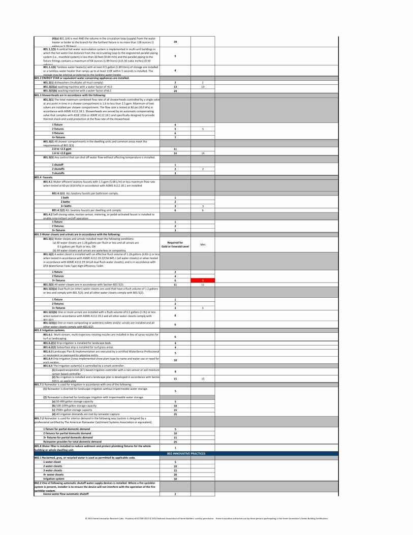
(4)(a) 801.1(4) is met AND the volume in the circulation loop (supply) from the water
heater or boiler to the branch for the furthest fixture is no more than 128 ounces (1
gallon or 3.78 liters).
39
801.1.1(5) A central hot water recirculation system is implemented in multi-unit buildings in
which the hot water line distance from the recirculating loop to the engineered parallel piping
system (i.e., manifold system) is less than 30 feet (9144 mm) and the parallel piping to the
fixture fittings contains a maximum of 64 ounces (1.89 liters) (115.50 cubic inches) (0.50
gallons).
9
801.1.1(6) Tankless water heater(s) with at least 0.5 gallon (1.89 liters) of storage are installed
or a tankless water heater that ramps up to at least 110F within 5 seconds is installed. The
storage may be internal or external to the tankless water heater.
4
801.2 ENERGY STAR or equivalent water conserving appliances are installed.
801.2(1) dishwashers (multiples all must comply) 2 2
801.2(2)(a) washing machine with a water factor of >6.0 13 13
801.2(2)(b) washing machine with a water factor of ≤6.0 24
801.3 Showerheads are in accordance with the following:
801.3(1) The total maximum combined flow rate of all showerheads controlled by a single valve
at any point in time in a shower compartment is 1.6 to less than 2.5 gpm. Maximum of two
valves are installed per shower compartment. The flow rate is tested at 80 psi (552 kPa) in
accordance with ASME A112.18.1. Showerheads are served by an automatic compensating
valve that complies with ASSE 1016 or ASME A112.18.1 and specifically designed to provide
thermal shock and scald protection at the flow rate of the showerhead.
1 fixture 4
2 fixtures 5 5
3 fixtures 6
4+ fixtures 7
801.3(2) All shower compartments in the dwelling units and common areas meet the
requirements of 801.3(1).
2.0 to <2.5 gpm 11
1.6 to <2.0 gpm 14 14
801.3(3) Any control that can shut off water flow without affecting temperature is installed.
1 shutoff 1
2 shutoffs 2 2
3 shutoffs 3
801.4 Faucets.
801.4.1 Water-efficient lavatory faucets with 1.5 gpm (5.68 L/m) or less maximum flow rate
when tested at 60 psi (414 kPa) in accordance with ASME A112.18.1 are installed:
801.4.1(1) ALL lavatory faucets per bathroom comply.
1 bath 1
2 baths 2
3+ baths 3 3
801.4.1(2) ALL lavatory faucets per dwelling unit comply. 6 6
801.4.2 Self-closing valve, motion sensor, metering, or pedal-activated faucet is installed to
enable intermittent on/off operation.
1 fixture 1
2 fixtures 2
3+ fixtures 3
801.5 Water closets and urinals are in accordance with the following:
801.5(1) Water closets and urinals installed meet the following conditions:
(a) All water closets are 1.28 gallons per flush or less and all urinals are
0.5 gallons per flush or less, OR
(b) All water closets and urinals are waterless or composting.
Required for
Gold or Emerald LevelMet
801.5(2) A water closet is installed with an effective flush volume of 1.28 gallons (4.85 L) or less
when tested in accordance with ASME A112.19.2/CSA B45.1 (all water closets) or when tested
in accordance with ASME A112.19.14 (all dual flush water closets), and is in accordance with
EPA WaterSense Tank-Type High-Efficiency Toilet.
1 fixture 2
2 fixtures 4
3+ fixtures 6 6
801.5(3) All water closets are in accordance with Section 801.5(2). 11 11
801.5(3)(a) Dual flush (or other) water closets are used that have a flush volume of 1.2 gallons
or less and comply with 801.5(2); and all other water closets comply with 801.5(2).
1 fixture 1
2 fixtures 2
3+ fixtures 3 3
801.5(3)(b) One or more urinals are installed with a flush volume of 0.5 gallons (1.9L) or less
when tested in accordance with ASME A112.19.2 and all other water closets comply with
801.6(2).
8
801.5(3)(c) One or more composting or waterless toilets and/or urinals are installed and all
other water closets comply with 801.6(2).6
801.6 Irrigation systems.
801.6.1 Multi-stream, multi-trajectory rotating nozzles are installed in lieu of spray nozzles for
turf or landscaping.6
801.6.2(1) Drip irrigation is installed for landscape beds. 4
801.6.2(2) Subsurface drip is installed for turf grass areas. 4
801.6.3 Landscape Plan & Implementation are executed by a certified WaterSense Professional
or equivalent as approved by adopting entity.5
801.6.4 Drip Irrigation Zones Implemented show plant type by name and water use or need for
each emitter.10
801.6.5 The irrigation system(s) is controlled by a smart controller.
(1) Evapotranspiration (ET) based irrigation controller with a rain sensor or soil moisture
sensor based controller.8
(2) No irrigation is installed and a landscape plan is developed in accordance with Section
503.5, as applicable.15 15
801.7.1 Rainwater is used for irrigation in accordance with one of the following:
(1) Rainwater is diverted for landscape irrigation without impermeable water storage.5
(2) Rainwater is diverted for landscape irrigation with impermeable water storage.
(a) 50-499 gallon storage capacity 5
(b) 500-2499 gallon storage capacity 10
(c) 2500+ gallon storage capacity 15
(d) All irrigation demands are met by rainwater capture 25
801.7.2 Rainwater is used for interior demand in the following way (system is designed by a
professional certified by The American Rainwater Catchment Systems Association or equivalent).
1 fixture for partial domestic demand 5
2 fixtures for partial domestic demand 10
3+ fixtures for partial domestic demand 15
Rainwater provides for total domestic demand 25
801.8 Water filter is installed to reduce sediment and protect plumbing fixtures for the whole
building or whole dwelling unit.1
802.1 Reclaimed, gray, or recycled water is used as permitted by applicable code.
1 water closet 5
2 water closets 10
3 water closets 15
4+ water closets 20
Irrigation system 10
802.2 One of following automatic shutoff water supply devices is installed. Where a fire sprinkler
system is present, installer is to ensure the device will not interfere with the operation of the fire
sprinkler system.Excess water flow automatic shutoff 2
802 INNOVATIVE PRACTICES
© 2013 Home Innovation Research Labs. Practices of ICC700-2012 © 2013 National Association of Home Builders- used by permission. Home Innovation authorizes use by those persons participating in the Home Innovation’s Green Building Certification.
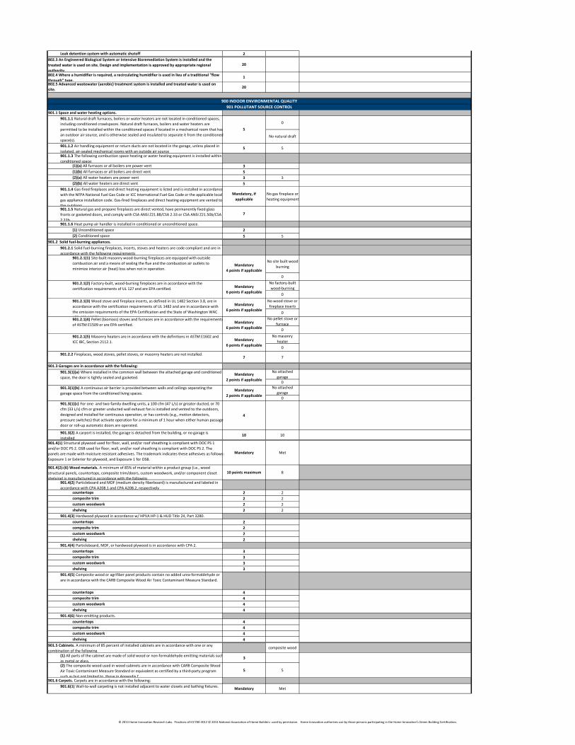
Leak detention system with automatic shutoff 2
802.3 An Engineered Biological System or Intensive Bioremediation System is installed and the
treated water is used on site. Design and implementation is approved by appropriate regional
authority.
20
802.4 Where a humidifier is required, a recirculating humidifier is used in lieu of a traditional “flow
through” type.1
802.5 Advanced wastewater (aerobic) treatment system is installed and treated water is used on
site.20
901.1 Space and water heating options.
0
No natural draft
901.1.2 Air handling equipment or return ducts are not located in the garage, unless placed in
isolated, air-sealed mechanical rooms with an outside air source.5 5
901.1.3 The following combustion space heating or water heating equipment is installed within
conditioned space:(1)(a) All furnaces or all boilers are power vent 3
(1)(b) All furnaces or all boilers are direct vent 5
(2)(a) All water heaters are power vent 3 3
(2)(b) All water heaters are direct vent 5
901.1.4 Gas-fired fireplaces and direct heating equipment is listed and is installed in accordance
with the NFPA National Fuel Gas Code or ICC International Fuel Gas Code or the applicable local
gas appliance installation code. Gas-fired fireplaces and direct heating equipment are vented to
the outdoors.
Mandatory, if
applicable
No gas fireplace or
heating equipment
901.1.5 Natural gas and propane fireplaces are direct vented, have permanently fixed glass
fronts or gasketed doors, and comply with CSA ANSI Z21.88/CSA 2.33 or CSA ANSI Z21.50b/CSA
2.22b.
7
901.1.6 Heat pump air handler is installed in conditioned or unconditioned space.
(1) Unconditioned space 2
(2) Conditioned space 5 5
901.2 Solid fuel-burning appliances.
901.2.1 Solid fuel-burning fireplaces, inserts, stoves and heaters are code compliant and are in
accordance with the following requirements:
No site built wood
burning
0
No factory-built
wood-burning
0
No wood stove or
fireplace inserts
0
No pellet stove or
furnace
0
No masonry
heater
0
901.2.2 Fireplaces, wood stoves, pellet stoves, or masonry heaters are not installed.7 7
901.3 Garages are in accordance with the following:
No attached
garage
0
No attached
garage
0
901.3(1)(c) For one- and two-family dwelling units, a 100 cfm (47 L/s) or greater ducted, or 70
cfm (33 L/s) cfm or greater unducted wall exhaust fan is installed and vented to the outdoors,
designed and installed for continuous operation, or has controls (e.g., motion detectors,
pressure switches) that activate operation for a minimum of 1 hour when either human passage
door or roll-up automatic doors are operated.
4
901.3(2) A carport is installed, the garage is detached from the building, or no garage is
installed.10 10
901.4(1) Structural plywood used for floor, wall, and/or roof sheathing is compliant with DOC PS 1
and/or DOC PS 2. OSB used for floor, wall, and/or roof sheathing is compliant with DOC PS 2. The
panels are made with moisture resistant adhesives. The trademark indicates these adhesives as follows:
Exposure 1 or Exterior for plywood, and Exposure 1 for OSB.
Mandatory Met
901.4(2)-(6) Wood materials. A minimum of 85% of material within a product group (i.e., wood
structural panels, countertops, composite trim/doors, custom woodwork, and/or component closet
shelving) is manufactured in accordance with the following:
10 points maximum 8
901.4(2) Particleboard and MDF (medium density fiberboard) is manufactured and labeled in
accordance with CPA A208.1 and CPA A208.2, respectively.countertops 2 2
composite trim 2 2
custom woodwork 2 2
shelving 2 2
901.4(3) Hardwood plywood in accordance w/ HPVA HP-1 & HUD Title 24, Part 3280.
countertops 2
composite trim 2
custom woodwork 2
shelving 2
901.4(4) Particleboard, MDF, or hardwood plywood is in accordance with CPA 2.
countertops 3
composite trim 3
custom woodwork 3
shelving 3
901.4(5) Composite wood or agrifiber panel products contain no added urea-formaldehyde or
are in accordance with the CARB Composite Wood Air Toxic Contaminant Measure Standard.
countertops 4
composite trim 4
custom woodwork 4
shelving 4
901.4(6) Non-emitting products.
countertops 4
composite trim 4
custom woodwork 4
shelving 4
901.5 Cabinets. A minimum of 85 percent of installed cabinets are in accordance with one or any
combination of the following.composite wood
(1) All parts of the cabinet are made of solid wood or non-formaldehyde emitting materials such
as metal or glass.3
(2) The composite wood used in wood cabinets are in accordance with CARB Composite Wood
Air Toxic Contaminant Measure Standard or equivalent as certified by a third-party program
such as but not limited to, those in Appendix D.
5 5
901.6 Carpets. Carpets are in accordance with the following:
901.6(1) Wall-to-wall carpeting is not installed adjacent to water closets and bathing fixtures.Mandatory Met
901.1.1 Natural draft furnaces, boilers or water heaters are not located in conditioned spaces,
including conditioned crawlspaces. Natural draft furnaces, boilers and water heaters are
permitted to be installed within the conditioned spaces if located in a mechanical room that has
an outdoor air source, and is otherwise sealed and insulated to separate it from the conditioned
space(s).
5
901.2.1(1) Site-built masonry wood-burning fireplaces are equipped with outside
combustion air and a means of sealing the flue and the combustion air outlets to
minimize interior air (heat) loss when not in operation.Mandatory
4 points if applicable
901.2.1(2) Factory-built, wood-burning fireplaces are in accordance with the
certification requirements of UL 127 and are EPA certified.Mandatory
6 points if applicable
901.2.1(5) Masonry heaters are in accordance with the definitions in ASTM E1602 and
ICC IBC, Section 2112.1.
901.3(1)(a) Where installed in the common wall between the attached garage and conditioned
space, the door is tightly sealed and gasketed.Mandatory
2 points if applicable
901.3(1)(b) A continuous air barrier is provided between walls and ceilings separating the
garage space from the conditioned living spaces.Mandatory
2 points if applicable
900 INDOOR ENVIRONMENTAL QUALITY
901 POLLUTANT SOURCE CONTROL
901.2.1(3) Wood stove and fireplace inserts, as defined in UL 1482 Section 3.8, are in
accordance with the certification requirements of UL 1482 and are in accordance with
the emission requirements of the EPA Certification and the State of Washington WAC
173-433-100(3).
Mandatory
6 points if applicable
901.2.1(4) Pellet (biomass) stoves and furnaces are in accordance with the requirements
of ASTM E1509 or are EPA certified.Mandatory
6 points if applicable
Mandatory
6 points if applicable
© 2013 Home Innovation Research Labs. Practices of ICC700-2012 © 2013 National Association of Home Builders- used by permission. Home Innovation authorizes use by those persons participating in the Home Innovation’s Green Building Certification.
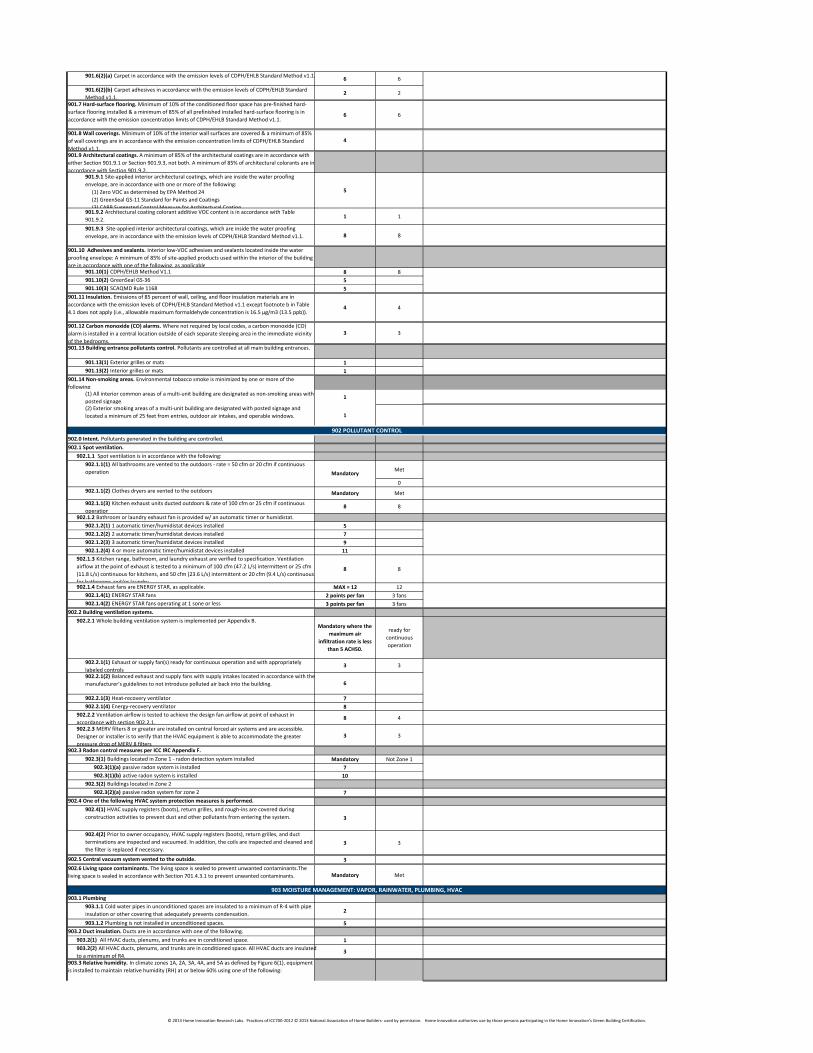
901.6(2)(a) Carpet in accordance with the emission levels of CDPH/EHLB Standard Method v1.1.6 6
901.6(2)(b) Carpet adhesives in accordance with the emission levels of CDPH/EHLB Standard
Method v1.1.2 2
901.7 Hard-surface flooring. Minimum of 10% of the conditioned floor space has pre-finished hard-
surface flooring installed & a minimum of 85% of all prefinished installed hard-surface flooring is in
accordance with the emission concentration limits of CDPH/EHLB Standard Method v1.1.6 6
901.8 Wall coverings. Minimum of 10% of the interior wall surfaces are covered & a minimum of 85%
of wall coverings are in accordance with the emission concentration limits of CDPH/EHLB Standard
Method v1.1.
4
901.9 Architectural coatings. A minimum of 85% of the architectural coatings are in accordance with
either Section 901.9.1 or Section 901.9.3, not both. A minimum of 85% of architectural colorants are in
accordance with Section 901.9.2.901.9.1 Site-applied interior architectural coatings, which are inside the water proofing
envelope, are in accordance with one or more of the following:
(1) Zero VOC as determined by EPA Method 24
(2) GreenSeal GS-11 Standard for Paints and Coatings
(3) CARB Suggested Control Measure for Architectural Coatings
5
901.9.2 Architectural coating colorant additive VOC content is in accordance with Table
901.9.2.1 1
901.9.3 Site-applied interior architectural coatings, which are inside the water proofing
envelope, are in accordance with the emission levels of CDPH/EHLB Standard Method v1.1. 8 8
901.10 Adhesives and sealants. Interior low-VOC adhesives and sealants located inside the water
proofing envelope: A minimum of 85% of site-applied products used within the interior of the building
are in accordance with one of the following, as applicable.901.10(1) CDPH/EHLB Method V1.1 8 8
901.10(2) GreenSeal GS-36 5
901.10(3) SCAQMD Rule 1168 5
901.11 Insulation. Emissions of 85 percent of wall, ceiling, and floor insulation materials are in
accordance with the emission levels of CDPH/EHLB Standard Method v1.1 except footnote b in Table
4.1 does not apply (i.e., allowable maximum formaldehyde concentration is 16.5 µg/m3 (13.5 ppb)).4 4
901.12 Carbon monoxide (CO) alarms. Where not required by local codes, a carbon monoxide (CO)
alarm is installed in a central location outside of each separate sleeping area in the immediate vicinity
of the bedrooms.
3 3
901.13 Building entrance pollutants control. Pollutants are controlled at all main building entrances.
901.13(1) Exterior grilles or mats 1
901.13(2) Interior grilles or mats 1
901.14 Non-smoking areas. Environmental tobacco smoke is minimized by one or more of the
following:
(1) All interior common areas of a multi-unit building are designated as non-smoking areas with
posted signage.1
(2) Exterior smoking areas of a multi-unit building are designated with posted signage and
located a minimum of 25 feet from entries, outdoor air intakes, and operable windows. 1
902.0 Intent. Pollutants generated in the building are controlled.
902.1 Spot ventilation.
902.1.1 Spot ventilation is in accordance with the following:
Met
0
902.1.1(2) Clothes dryers are vented to the outdoors Mandatory Met
902.1.1(3) Kitchen exhaust units ducted outdoors & rate of 100 cfm or 25 cfm if continuous
operation8 8
902.1.2 Bathroom or laundry exhaust fan is provided w/ an automatic timer or humidistat.
902.1.2(1) 1 automatic timer/humidistat devices installed 5
902.1.2(2) 2 automatic timer/humidistat devices installed 7
902.1.2(3) 3 automatic timer/humidistat devices installed 9
902.1.2(4) 4 or more automatic timer/humidistat devices installed 11
902.1.3 Kitchen range, bathroom, and laundry exhaust are verified to specification. Ventilation
airflow at the point of exhaust is tested to a minimum of 100 cfm (47.2 L/s) intermittent or 25 cfm
(11.8 L/s) continuous for kitchens, and 50 cfm (23.6 L/s) intermittent or 20 cfm (9.4 L/s) continuous
for bathrooms and/or laundry.
8 8
902.1.4 Exhaust fans are ENERGY STAR, as applicable. MAX = 12 12
902.1.4(1) ENERGY STAR fans 2 points per fan 3 fans
902.1.4(2) ENERGY STAR fans operating at 1 sone or less 3 points per fan 3 fans
902.2 Building ventilation systems.
902.2.1 Whole building ventilation system is implemented per Appendix B. Mandatory where the
maximum air
infiltration rate is less
than 5 ACH50.
ready for
continuous
operation
902.2.1(1) Exhaust or supply fan(s) ready for continuous operation and with appropriately
labeled controls.3 3
902.2.1(2) Balanced exhaust and supply fans with supply intakes located in accordance with the
manufacturer's guidelines to not introduce polluted air back into the building. 6
902.2.1(3) Heat-recovery ventilator 7
902.2.1(4) Energy-recovery ventilator 8
902.2.2 Ventilation airflow is tested to achieve the design fan airflow at point of exhaust in
accordance with section 902.2.1.8 4
902.2.3 MERV filters 8 or greater are installed on central forced air systems and are accessible.
Designer or installer is to verify that the HVAC equipment is able to accommodate the greater
pressure drop of MERV 8 filters.
3 3
902.3 Radon control measures per ICC IRC Appendix F.
902.3(1) Buildings located in Zone 1 - radon detection system installed Mandatory Not Zone 1
902.3(1)(a) passive radon system is installed 7
902.3(1)(b) active radon system is installed 10
902.3(2) Buildings located in Zone 2
902.3(2)(a) passive radon system for zone 2 7
902.4 One of the following HVAC system protection measures is performed.
902.4(1) HVAC supply registers (boots), return grilles, and rough-ins are covered during
construction activities to prevent dust and other pollutants from entering the system. 3
902.4(2) Prior to owner occupancy, HVAC supply registers (boots), return grilles, and duct
terminations are inspected and vacuumed. In addition, the coils are inspected and cleaned and
the filter is replaced if necessary.
3 3
902.5 Central vacuum system vented to the outside. 3
902.6 Living space contaminants. The living space is sealed to prevent unwanted contaminants.The
living space is sealed in accordance with Section 701.4.3.1 to prevent unwanted contaminants. Mandatory Met
903.1 Plumbing
903.1.1 Cold water pipes in unconditioned spaces are insulated to a minimum of R-4 with pipe
insulation or other covering that adequately prevents condensation.2
903.1.2 Plumbing is not installed in unconditioned spaces. 5
903.2 Duct insulation. Ducts are in accordance with one of the following.
903.2(1) All HVAC ducts, plenums, and trunks are in conditioned space. 1
903.2(2) All HVAC ducts, plenums, and trunks are in conditioned space. All HVAC ducts are insulated
to a minimum of R4.3
903.3 Relative humidity. In climate zones 1A, 2A, 3A, 4A, and 5A as defined by Figure 6(1), equipment
is installed to maintain relative humidity (RH) at or below 60% using one of the following:
902 POLLUTANT CONTROL
903 MOISTURE MANAGEMENT: VAPOR, RAINWATER, PLUMBING, HVAC
902.1.1(1) All bathrooms are vented to the outdoors - rate = 50 cfm or 20 cfm if continuous
operation Mandatory
© 2013 Home Innovation Research Labs. Practices of ICC700-2012 © 2013 National Association of Home Builders- used by permission. Home Innovation authorizes use by those persons participating in the Home Innovation’s Green Building Certification.
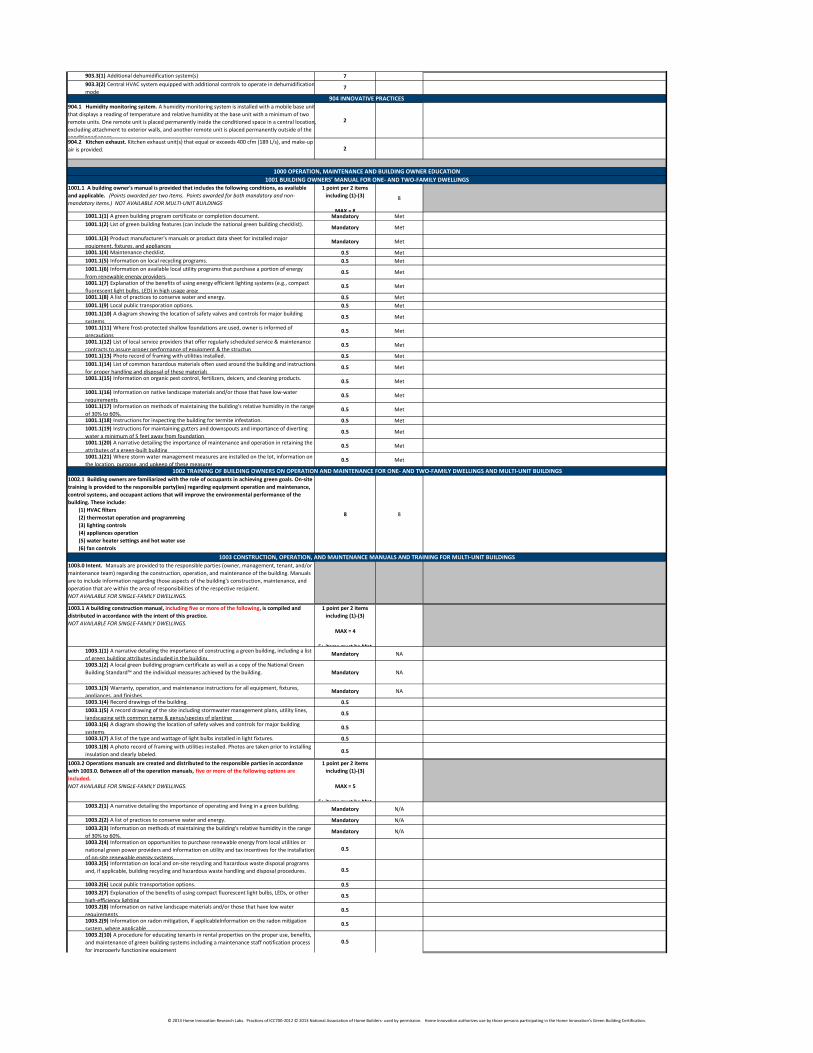
903.3(1) Additional dehumidification system(s) 7
903.3(2) Central HVAC system equipped with additional controls to operate in dehumidification
mode7
904.1 Humidity monitoring system. A humidity monitoring system is installed with a mobile base unit
that displays a reading of temperature and relative humidity at the base unit with a minimum of two
remote units. One remote unit is placed permanently inside the conditioned space in a central location,
excluding attachment to exterior walls, and another remote unit is placed permanently outside of the
conditioned space.
2
904.2 Kitchen exhaust. Kitchen exhaust unit(s) that equal or exceeds 400 cfm (189 L/s), and make-up
air is provided. 2
1001.1 A building owner's manual is provided that includes the following conditions, as available
and applicable. (Points awarded per two items. Points awarded for both mandatory and non-
mandatory items.) NOT AVAILABLE FOR MULTI-UNIT BUILDINGS
1 point per 2 items
including (1)-(3)
MAX = 8
8
1001.1(1) A green building program certificate or completion document. Mandatory Met
1001.1(2) List of green building features (can include the national green building checklist).Mandatory Met
1001.1(3) Product manufacturer's manuals or product data sheet for installed major
equipment, fixtures, and appliances.Mandatory Met
1001.1(4) Maintenance checklist. 0.5 Met
1001.1(5) Information on local recycling programs. 0.5 Met
1001.1(6) Information on available local utility programs that purchase a portion of energy
from renewable energy providers.0.5 Met
1001.1(7) Explanation of the benefits of using energy efficient lighting systems (e.g., compact
fluorescent light bulbs, LED) in high usage areas.0.5 Met
1001.1(8) A list of practices to conserve water and energy. 0.5 Met
1001.1(9) Local public transporation options. 0.5 Met
1001.1(10) A diagram showing the location of safety valves and controls for major building
systems.0.5 Met
1001.1(11) Where frost-protected shallow foundations are used, owner is informed of
precautions.0.5 Met
1001.1(12) List of local service providers that offer regularly scheduled service & maintenance
contracts to assure proper performance of equipment & the structure0.5 Met
1001.1(13) Photo record of framing with utilities installed. 0.5 Met
1001.1(14) List of common hazardous materials often used around the building and instructions
for proper handling and disposal of these materials.0.5 Met
1001.1(15) Information on organic pest control, fertilizers, deicers, and cleaning products.0.5 Met
1001.1(16) Information on native landscape materials and/or those that have low-water
requirements.0.5 Met
1001.1(17) Information on methods of maintaining the building's relative humidity in the range
of 30% to 60%.0.5 Met
1001.1(18) Instructions for inspecting the building for termite infestation. 0.5 Met
1001.1(19) Instructions for maintaining gutters and downspouts and importance of diverting
water a minimum of 5 feet away from foundation.0.5 Met
1001.1(20) A narrative detailing the importance of maintenance and operation in retaining the
attributes of a green-built building.0.5 Met
1001.1(21) Where storm water management measures are installed on the lot, information on
the location, purpose, and upkeep of these measures.0.5 Met
1002.1 Building owners are familiarized with the role of occupants in achieving green goals. On-site
training is provided to the responsible party(ies) regarding equipment operation and maintenance,
control systems, and occupant actions that will improve the environmental performance of the
building. These include:
(1) HVAC filters
(2) thermostat operation and programming
(3) lighting controls
(4) appliances operation
(5) water heater settings and hot water use
(6) fan controls
(7) recycling practices
8 8
1003.0 Intent. Manuals are provided to the responsible parties (owner, management, tenant, and/or
maintenance team) regarding the construction, operation, and maintenance of the building. Manuals
are to include information regarding those aspects of the building's construction, maintenance, and
operation that are within the area of responsibilities of the respective recipient.
NOT AVAILABLE FOR SINGLE-FAMILY DWELLINGS.
1003.1 A building construction manual, including five or more of the following, is compiled and
distributed in accordance with the intent of this practice.
NOT AVAILABLE FOR SINGLE-FAMILY DWELLINGS.
1 point per 2 items
including (1)-(3)
MAX = 4
5+ items must be Met1003.1(1) A narrative detailing the importance of constructing a green building, including a list
of green building attributes included in the building.Mandatory NA
1003.1(2) A local green building program certificate as well as a copy of the National Green
Building Standard™ and the individual measures achieved by the building. Mandatory NA
1003.1(3) Warranty, operation, and maintenance instructions for all equipment, fixtures,
appliances, and finishes.Mandatory NA
1003.1(4) Record drawings of the building. 0.5
1003.1(5) A record drawing of the site including stormwater management plans, utility lines,
landscaping with common name & genus/species of plantings.0.5
1003.1(6) A diagram showing the location of safety valves and controls for major building
systems.0.5
1003.1(7) A list of the type and wattage of light bulbs installed in light fixtures. 0.5
1003.1(8) A photo record of framing with utilities installed. Photos are taken prior to installing
insulation and clearly labeled.0.5
1003.2 Operations manuals are created and distributed to the responsible parties in accordance
with 1003.0. Between all of the operation manuals, five or more of the following options are
included.
NOT AVAILABLE FOR SINGLE-FAMILY DWELLINGS.
1 point per 2 items
including (1)-(3)
MAX = 5
5+ items must be Met1003.2(1) A narrative detailing the importance of operating and living in a green building.
Mandatory N/A
1003.2(2) A list of practices to conserve water and energy. Mandatory N/A
1003.2(3) Information on methods of maintaining the building's relative humidity in the range
of 30% to 60%.Mandatory N/A
1003.2(4) Information on opportunities to purchase renewable energy from local utilities or
national green power providers and information on utility and tax incentives for the installation
of on-site renewable energy systems.
0.5
1003.2(5) Informtation on local and on-site recycling and hazardous waste disposal programs
and, if applicable, building recycling and hazardous waste handling and disposal procedures. 0.5
1003.2(6) Local public transportation options. 0.5
1003.2(7) Explanation of the benefits of using compact fluorescent light bulbs, LEDs, or other
high-efficiency lighting.0.5
1003.2(8) Information on native landscape materials and/or those that have low water
requirements.0.5
1003.2(9) Information on radon mitigation, if applicableInformation on the radon mitigation
system, where applicable.0.5
1003.2(10) A procedure for educating tenants in rental properties on the proper use, benefits,
and maintenance of green building systems including a maintenance staff notification process
for improperly functioning equipment.
0.5
904 INNOVATIVE PRACTICES
1000 OPERATION, MAINTENANCE AND BUILDING OWNER EDUCATION
1001 BUILDING OWNERS’ MANUAL FOR ONE- AND TWO-FAMILY DWELLINGS
1002 TRAINING OF BUILDING OWNERS ON OPERATION AND MAINTENANCE FOR ONE- AND TWO-FAMILY DWELLINGS AND MULTI-UNIT BUILDINGS
1003 CONSTRUCTION, OPERATION, AND MAINTENANCE MANUALS AND TRAINING FOR MULTI-UNIT BUILDINGS
© 2013 Home Innovation Research Labs. Practices of ICC700-2012 © 2013 National Association of Home Builders- used by permission. Home Innovation authorizes use by those persons participating in the Home Innovation’s Green Building Certification.
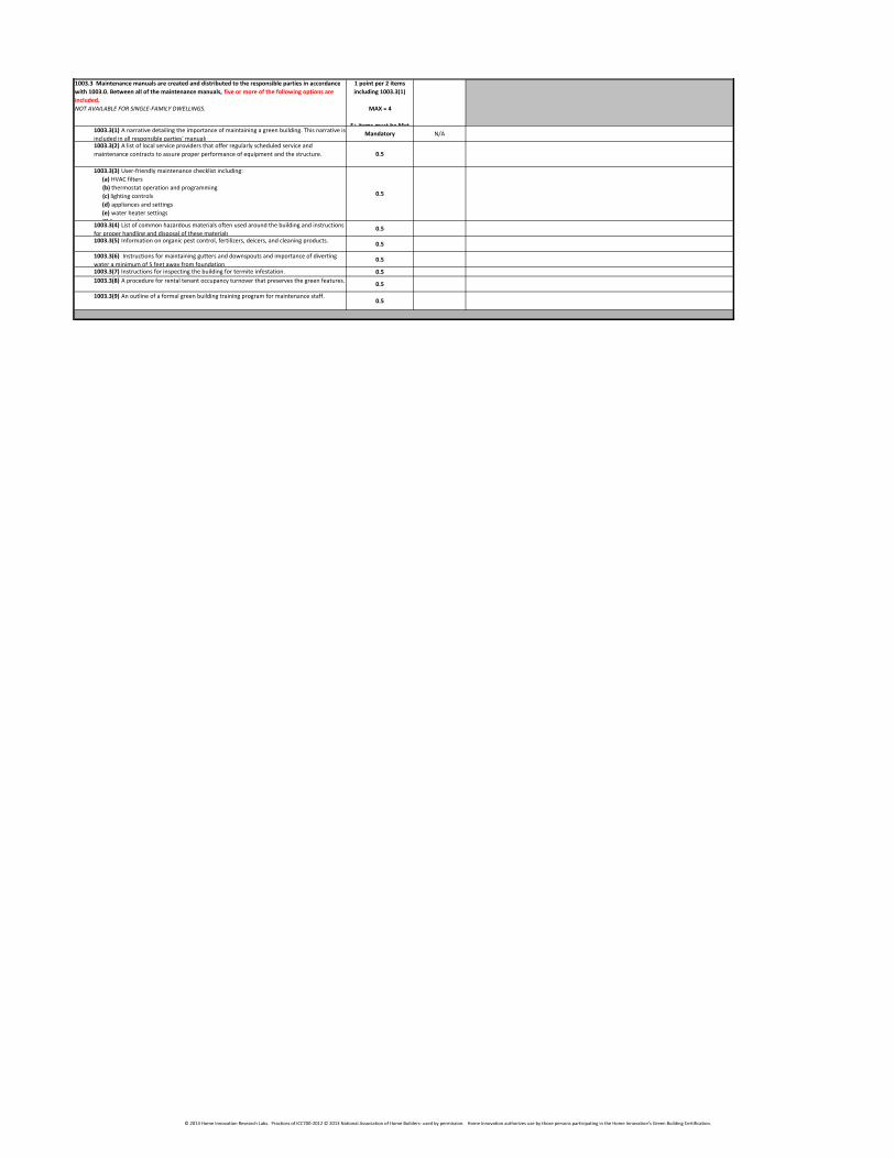
1003.3 Maintenance manuals are created and distributed to the responsible parties in accordance
with 1003.0. Between all of the maintenance manuals, five or more of the following options are
included.
NOT AVAILABLE FOR SINGLE-FAMILY DWELLINGS.
1 point per 2 items
including 1003.3(1)
MAX = 4
5+ items must be Met1003.3(1) A narrative detailing the importance of maintaining a green building. This narrative is
included in all responsible parties' manuals.Mandatory N/A
1003.3(2) A list of local service providers that offer regularly scheduled service and
maintenance contracts to assure proper performance of equipment and the structure. 0.5
1003.3(3) User-friendly maintenance checklist including:
(a) HVAC filters
(b) thermostat operation and programming
(c) lighting controls
(d) appliances and settings
(e) water heater settings
(f) fan controls
0.5
1003.3(4) List of common hazardous materials often used around the building and instructions
for proper handling and disposal of these materials.0.5
1003.3(5) Information on organic pest control, fertilizers, deicers, and cleaning products.0.5
1003.3(6) Instructions for maintaining gutters and downspouts and importance of diverting
water a minimum of 5 feet away from foundation.0.5
1003.3(7) Instructions for inspecting the building for termite infestation. 0.5
1003.3(8) A procedure for rental tenant occupancy turnover that preserves the green features.0.5
1003.3(9) An outline of a formal green building training program for maintenance staff.0.5
© 2013 Home Innovation Research Labs. Practices of ICC700-2012 © 2013 National Association of Home Builders- used by permission. Home Innovation authorizes use by those persons participating in the Home Innovation’s Green Building Certification.
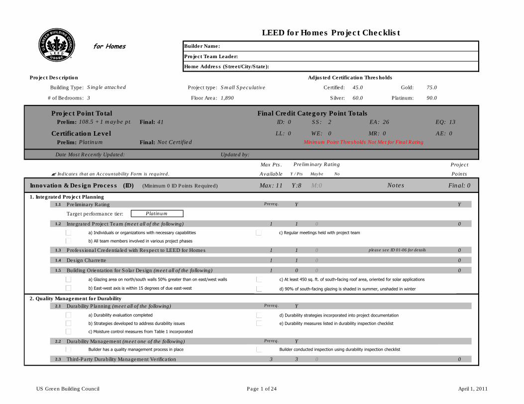
for Homes
Project Team Leader:
Home Address (Street/City/State):
Project Description Adjusted Certification Thresholds
Building Type: Project type: Small Speculative Certified: 45.0 Gold: 75.0
# of Bedrooms: 3 Floor Area: 1,890 Silver: 60.0 Platinum: 90.0
Project Point Total Final Credit Category Point Totals Prelim: Final: 41 ID: 0 SS: 2 EA: 26 EQ: 13
Certification Level LL: 0 WE: 0 MR: 0 AE: 0
Prelim: Final:
Date Most Recently Updated: Updated by: 108.5 1 41.0
Max Pts. Project
���� Indicates that an Accountability Form is required. Available Y / Pts Maybe No Points
Innovation & Design Process (ID) (Minimum 0 ID Points Required) Max: 11 Y:8 M:0 Final: 0
1. Integrated Project Planning 8 0 01.1 Preliminary Rating Prereq. Y Y
Target performance tier:
1.2 Integrated Project Team (meet all of the following) 1 1 0 0
1.3 Professional Credentialed with Respect to LEED for Homes 1 1 0 0
1.4 Design Charrette 1 1 0 0
1.5 Building Orientation for Solar Design (meet all of the following) 1 0 0 0
2. Quality Management for Durability
2.1 Durability Planning (meet all of the following) Prereq. Y
2.2 Durability Management (meet one of the following) Prereq. Y
2.3 Third-Party Durability Management Verification 3 3 0 0
Notes
Platinum
please see ID 01-06 for details
Minimum Point Thresholds Not Met for Final Rating
Preliminary Rating
LEED for Homes Project Checklist
Builder Name:
Platinum
108.5 + 1 maybe pts
Single attached
Not Certified
a) Individuals or organizations with necessary capabilities c) Regular meetings held with project team
b) All team members involved in various project phases
a) Durability evaluation completed
c) Moisture control measures from Table 1 incorporated
b) Strategies developed to address durability issues
a) Glazing area on north/south walls 50% greater than on east/west walls c) At least 450 sq. ft. of south-facing roof area, oriented for solar applications
b) East-west axis is within 15 degrees of due east-west d) 90% of south-facing glazing is shaded in summer, unshaded in winter
Builder has a quality management process in place Builder conducted inspection using durability inspection checklist
d) Durability strategies incorporated into project documentation
e) Durability measures listed in durability inspection checklist
US Green Building Council Page 1 of 24 April 1, 2011
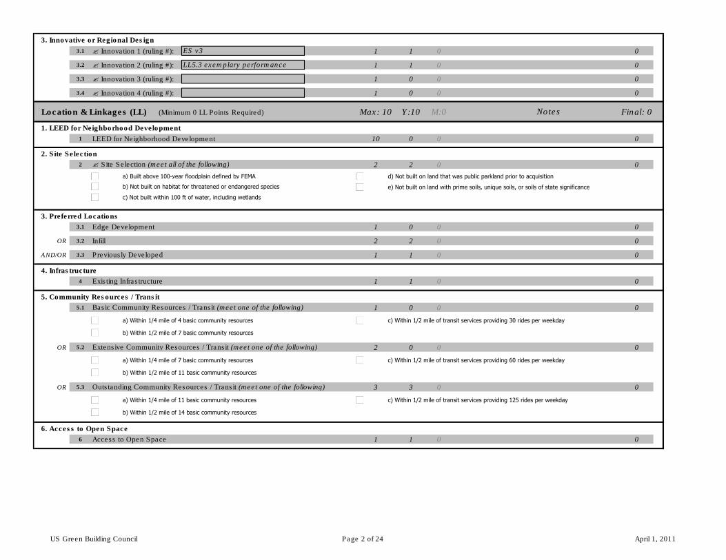
3. Innovative or Regional Design
3.1 � Innovation 1 (ruling #): 1 1 0 0
3.2 � Innovation 2 (ruling #): 1 1 0 0
3.3 � Innovation 3 (ruling #): 1 0 0 0
3.4 � Innovation 4 (ruling #): 1 0 0 0
Location & Linkages (LL) (Minimum 0 LL Points Required) Max: 10 Y:10 M:0 Final: 0
1. LEED for Neighborhood Development 10 0 0
1 LEED for Neighborhood Development 10 0 0 0
2. Site Selection
2 � Site Selection (meet all of the following) 2 2 0 0
3. Preferred Locations
3.1 Edge Development 1 0 0 0
OR 3.2 Infill 2 2 0 0
AND/OR 3.3 Previously Developed 1 1 0 0
4. Infrastructure
4 Existing Infrastructure 1 1 0 0
5. Community Resources / Transit
5.1 Basic Community Resources / Transit (meet one of the following) 1 0 0 0
OR 5.2 Extensive Community Resources / Transit (meet one of the following) 2 0 0 0
OR 5.3 Outstanding Community Resources / Transit (meet one of the following) 3 3 0 0
6. Access to Open Space
6 Access to Open Space 1 1 0 0
Notes
ES v3
LL5.3 exemplary performance
a) Built above 100-year floodplain defined by FEMA
c) Not built within 100 ft of water, including wetlands
b) Not built on habitat for threatened or endangered species
d) Not built on land that was public parkland prior to acquisition
e) Not built on land with prime soils, unique soils, or soils of state significance
a) Within 1/4 mile of 4 basic community resources c) Within 1/2 mile of transit services providing 30 rides per weekday
b) Within 1/2 mile of 7 basic community resources
a) Within 1/4 mile of 7 basic community resources c) Within 1/2 mile of transit services providing 60 rides per weekday
b) Within 1/2 mile of 11 basic community resources
a) Within 1/4 mile of 11 basic community resources c) Within 1/2 mile of transit services providing 125 rides per weekday
b) Within 1/2 mile of 14 basic community resources
US Green Building Council Page 2 of 24 April 1, 2011
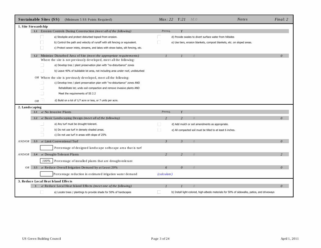
Sustainable Sites (SS) (Minimum 5 SS Points Required) Max: 22 Y:21 M:0 Final: 2
1. Site Stewardship 21 0 2
1.1 Erosion Controls During Construction (meet all of the following) Prereq. Y
1.2 Minimize Disturbed Area of Site (meet the appropriate requirements) 1 1 0 0
Where the site is not previously developed, meet all the following:
OR Where the site is previously developed, meet all the following:
OR
2. Landscaping
2.1 � No Invasive Plants Prereq. Y
2.2 � Basic Landscaping Design (meet all of the following) 2 2 0 0
AND/OR 2.3 � Limit Conventional Turf 3 3 0 0
Percentage of designed landscape softscape area that is turf
AND/OR 2.4 � Drought-Tolerant Plants 2 2 0 2
Percentage of installed plants that are drought-tolerant
OR 2.5 � Reduce Overall Irrigation Demand by at Least 20% 6 0 0 0
Percentage reduction in estimated irrigation water demand (calculate)
3. Reduce Local Heat Island Effects
3 � Reduce Local Heat Island Effects (meet one of the following) 1 1 0 0
Notes
100%
a) Stockpile and protect disturbed topsoil from erosion.
c) Protect sewer inlets, streams, and lakes with straw bales, silt fencing, etc.
b) Control the path and velocity of runoff with silt fencing or equivalent.
d) Provide swales to divert surface water from hillsides
e) Use tiers, erosion blankets, compost blankets, etc. on sloped areas.
b) Leave 40% of buildable lot area, not including area under roof, undisturbed
a) Develop tree / plant preservation plan with "no-disturbance" zones
c) Develop tree / plant preservation plan with "no-disturbance" zones AND
Rehabilitate lot; undo soil compaction and remove invasive plants AND
Meet the requirements of SS 2.2
d) Build on a lot of 1/7 acre or less, or 7 units per acre.
a) Any turf must be drought-tolerant.
c) Do not use turf in areas with slope of 25%
b) Do not use turf in densely shaded areas.
d) Add mulch or soil amendments as appropriate.
e) All compacted soil must be tilled to at least 6 inches.
a) Locate trees / plantings to provide shade for 50% of hardscapes b) Install light-colored, high-albedo materials for 50% of sidewalks, patios, and driveways
US Green Building Council Page 3 of 24 April 1, 2011
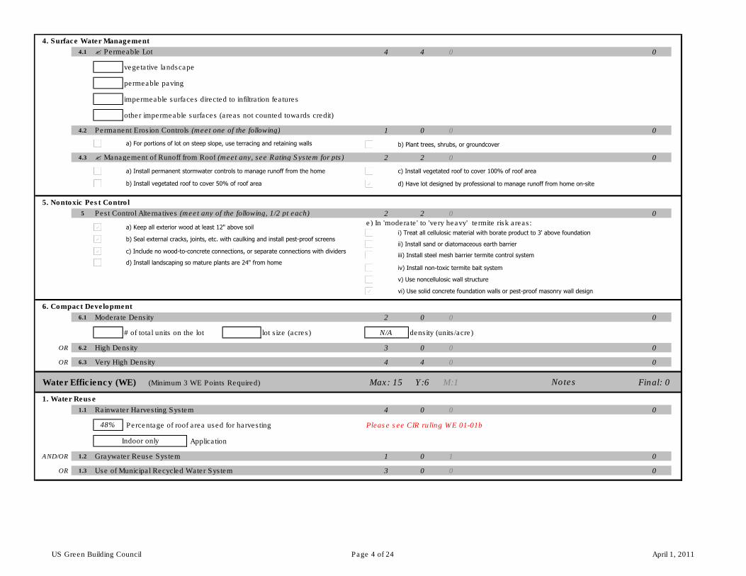
4. Surface Water Management
4.1 � Permeable Lot 4 4 0 0
vegetative landscape
permeable paving
impermeable surfaces directed to infiltration features
other impermeable surfaces (areas not counted towards credit)
4.2 Permanent Erosion Controls (meet one of the following) 1 0 0 0
4.3 � Management of Runoff from Roof (meet any, see Rating System for pts) 2 2 0 0
5. Nontoxic Pest Control
5 Pest Control Alternatives (meet any of the following, 1/2 pt each) 2 2 0 0
e) In 'moderate' to 'very heavy' termite risk areas:
6. Compact Development
6.1 Moderate Density 2 0 0 0
# of total units on the lot lot size (acres) N/A density (units/acre)
OR 6.2 High Density 3 0 0 0
OR 6.3 Very High Density 4 4 0 0
Water Efficiency (WE) (Minimum 3 WE Points Required) Max: 15 Y:6 M:1 Final: 0
1. Water Reuse 6 1 0
1.1 Rainwater Harvesting System 4 0 0 0
Percentage of roof area used for harvesting Please see CIR ruling WE 01-01b
Application
AND/OR 1.2 Graywater Reuse System 1 0 1 0
OR 1.3 Use of Municipal Recycled Water System 3 0 0 0
Indoor only
48%
Notes
a) For portions of lot on steep slope, use terracing and retaining walls b) Plant trees, shrubs, or groundcover
a) Install permanent stormwater controls to manage runoff from the home c) Install vegetated roof to cover 100% of roof area
b) Install vegetated roof to cover 50% of roof area d) Have lot designed by professional to manage runoff from home on-site
a) Keep all exterior wood at least 12" above soil
c) Include no wood-to-concrete connections, or separate connections with dividers
b) Seal external cracks, joints, etc. with caulking and install pest-proof screens
d) Install landscaping so mature plants are 24" from home
i) Treat all cellulosic material with borate product to 3' above foundation
ii) Install sand or diatomaceous earth barrier
iii) Install steel mesh barrier termite control system
iv) Install non-toxic termite bait system
v) Use noncellulosic wall structure
vi) Use solid concrete foundation walls or pest-proof masonry wall design
US Green Building Council Page 4 of 24 April 1, 2011
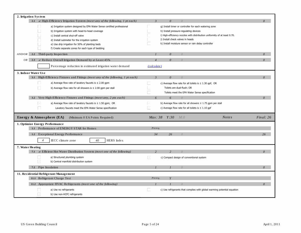
2. Irrigation System
2.1 � High-Efficiency Irrigation System (meet any of the following, 1 pt each) 3 0 0 0
AND/OR 2.2 Third-party Inspection 1 0 0 0
OR 2.3 � Reduce Overall Irrigation Demand by at Least 45% 4 0 0 0
Percentage reduction in estimated irrigation water demand (calculate)
3. Indoor Water Use
3.1 High-Efficiency Fixtures and Fittings (meet any of the following, 1 pt each) 3 0 0 0
3.2 Very High-Efficiency Fixtures and Fittings (meet any, 2 pts each) 6 6 0 0
Energy & Atmosphere (EA) (Minimum 0 EA Points Required) Max: 38 Y:30 M:0 Final: 26
1. Optimize Energy Performance 30.0 0.0 26.0
1.1 Performance of ENERGY STAR for Homes Prereq.
1.2 Exceptional Energy Performance 34 26 0 26
IECC climate zone 40 HERS Index
7. Water Heating
7.1 � Efficient Hot Water Distribution System (meet one of the following) 2 2 0 0
7.2 Pipe Insulation 1 1 0 0
11. Residential Refrigerant Management
11.1 Refrigerant Charge Test Prereq. Y
11.2 Appropriate HVAC Refrigerants (meet one of the following) 1 1 0 0
Notes
4
a) Irrigation system designed by EPA Water Sense certified professional
c) Install central shut-off valve
b) Irrigation system with head-to-head coverage
d) Install submeter for the irrigation system
e) Use drip irrigation for 50% of planting beds
f) Create separate zones for each type of bedding
g) Install timer or controller for each watering zone
h) Install pressure-regulating devices
i) High-efficiency nozzles with distribution uniformity of at least 0.70.
j) Install check valves in heads
k) Install moisture sensor or rain delay controller
a) Average flow rate of lavatory faucets is ≤ 2.00 gpm c) Average flow rate for all toilets is ≤ 1.30 gpf; OR
b) Average flow rate for all showers is ≤ 2.00 gpm per stall Toilets are dual-flush; OR
Toilets meet the EPA Water Sense specification
a) Average flow rate of lavatory faucets is ≤ 1.50 gpm; OR b) Average flow rate for all showers ≤ 1.75 gpm per stall
Lavatory faucets meet the EPA Water Sense specification c) Average flow rate for all toilets is ≤ 1.10 gpf
a) Structured plumbing system c) Compact design of conventional system
b) Central manifold distribution system
a) Use no refrigerants c) Use refrigerants that complies with global warming potential equation
b) Use non-HCFC refrigerants
US Green Building Council Page 5 of 24 April 1, 2011
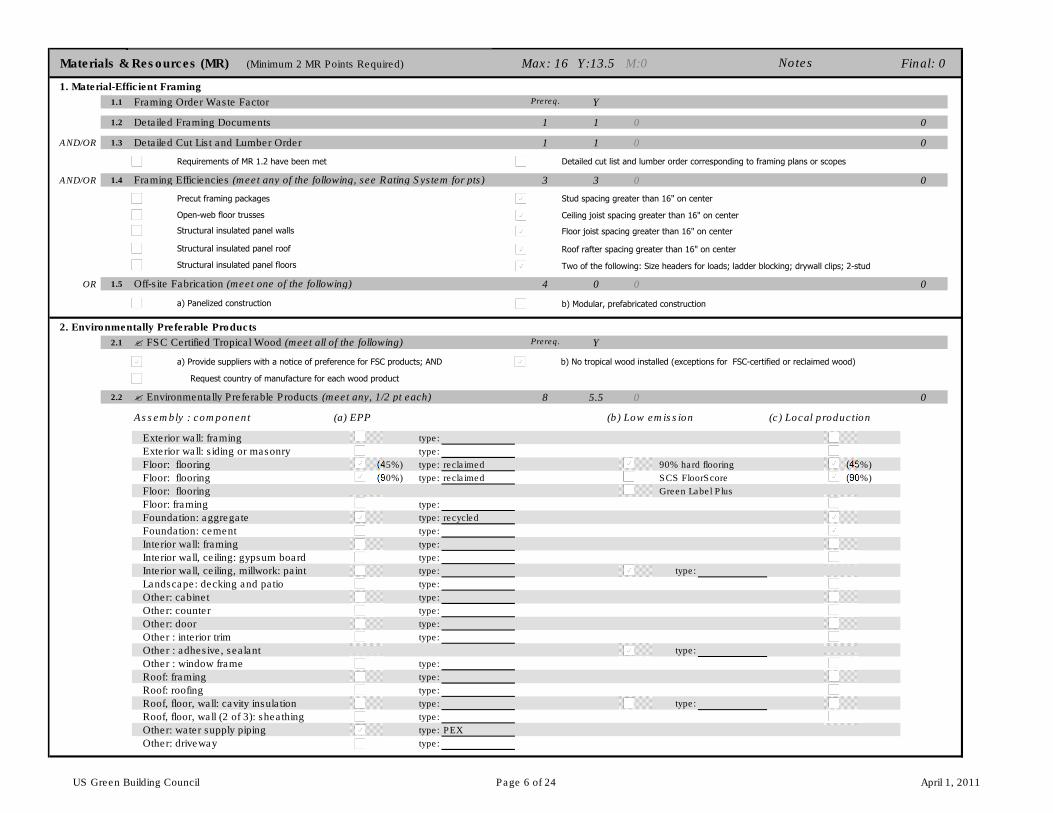
Materials & Resources (MR) (Minimum 2 MR Points Required) Max: 16 Y:13.5 M:0 Final: 0
1. Material-Efficient Framing 13.5 0 0
1.1 Framing Order Waste Factor Prereq. Y
1.2 Detailed Framing Documents 1 1 0 0
AND/OR 1.3 Detailed Cut List and Lumber Order 1 1 0 0
AND/OR 1.4 Framing Efficiencies (meet any of the following, see Rating System for pts) 3 3 0 0
OR 1.5 Off-site Fabrication (meet one of the following) 4 0 0 0
2. Environmentally Preferable Products
2.1 � FSC Certified Tropical Wood (meet all of the following) Prereq. Y
2.2 � Environmentally Preferable Products (meet any, 1/2 pt each) 8 5.5 0 0
Assembly : component (a) EPP (b) Low emission (c) Local production
Exterior wall: framing type:
Exterior wall: siding or masonry type:
Floor: flooring (45%) type: reclaimed 90% hard flooring (45%)
Floor: flooring (90%) type: reclaimed SCS FloorScore (90%)
Floor: flooring Green Label Plus
Floor: framing type:
Foundation: aggregate type: recycled
Foundation: cement type:
Interior wall: framing type:
Interior wall, ceiling: gypsum board type:
Interior wall, ceiling, millwork: paint type: type:
Landscape: decking and patio type:
Other: cabinet type:
Other: counter type:
Other: door type:
Other : interior trim type:
Other : adhesive, sealant type:
Other : window frame type:
Roof: framing type:
Roof: roofing type:
Roof, floor, wall: cavity insulation type: type:
Roof, floor, wall (2 of 3): sheathing type:
Other: water supply piping type: PEX
Other: driveway type:
Notes
Precut framing packages
Structural insulated panel walls
Open-web floor trusses
Structural insulated panel roof
Stud spacing greater than 16" on center
Structural insulated panel floors
Ceiling joist spacing greater than 16" on center
Roof rafter spacing greater than 16" on center
Floor joist spacing greater than 16" on center
Two of the following: Size headers for loads; ladder blocking; drywall clips; 2-stud
a) Panelized construction b) Modular, prefabricated construction
a) Provide suppliers with a notice of preference for FSC products; AND b) No tropical wood installed (exceptions for FSC-certified or reclaimed wood)
Requirements of MR 1.2 have been met Detailed cut list and lumber order corresponding to framing plans or scopes
Request country of manufacture for each wood product
US Green Building Council Page 6 of 24 April 1, 2011
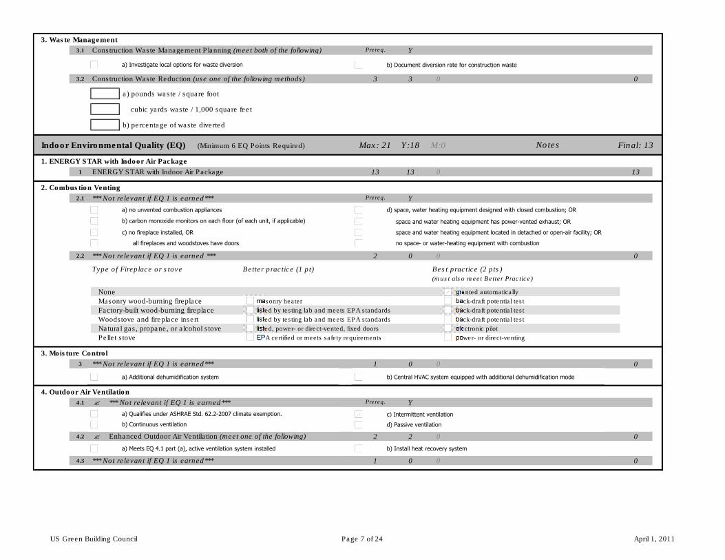
3. Waste Management
3.1 Construction Waste Management Planning (meet both of the following) Prereq. Y
3.2 Construction Waste Reduction (use one of the following methods) 3 3 0 0
a) pounds waste / square foot 0
cubic yards waste / 1,000 square feet 0
b) percentage of waste diverted 0
Indoor Environmental Quality (EQ) (Minimum 6 EQ Points Required) Max: 21 Y:18 M:0 Final: 13
1. ENERGY STAR with Indoor Air Package 18 0 13
1 ENERGY STAR with Indoor Air Package 13 13 0 13
2. Combustion Venting
2.1 *** Not relevant if EQ 1 is earned*** Prereq. Y
2.2 *** Not relevant if EQ 1 is earned *** 2 0 0 0
Type of Fireplace or stove Better practice (1 pt) Best practice (2 pts)
(must also meet Better Practice)
None granted automatically
Masonry wood-burning fireplace masonry heater back-draft potential test
Factory-built wood-burning fireplace listed by testing lab and meets EPA standards back-draft potential test
Woodstove and fireplace insert listed by testing lab and meets EPA standards back-draft potential test
Natural gas, propane, or alcohol stove listed, power- or direct-vented, fixed doors electronic pilot
Pellet stove EPA certified or meets safety requirements power- or direct-venting
3. Moisture Control
3 *** Not relevant if EQ 1 is earned*** 1 0 0 0
4. Outdoor Air Ventilation
4.1 � *** Not relevant if EQ 1 is earned*** Prereq. Y
4.2 � Enhanced Outdoor Air Ventilation (meet one of the following) 2 2 0 0
4.3 *** Not relevant if EQ 1 is earned*** 1 0 0 0
Notes
a) Investigate local options for waste diversion
a) no unvented combustion appliances
c) no fireplace installed, OR
b) carbon monoxide monitors on each floor (of each unit, if applicable)
d) space, water heating equipment designed with closed combustion; OR
space and water heating equipment located in detached or open-air facility; OR
space and water heating equipment has power-vented exhaust; OR
no space- or water-heating equipment with combustion
b) Central HVAC system equipped with additional dehumidification mode
a) Qualifies under ASHRAE Std. 62.2-2007 climate exemption. c) Intermittent ventilation
b) Continuous ventilation d) Passive ventilation
a) Meets EQ 4.1 part (a), active ventilation system installed b) Install heat recovery system
b) Document diversion rate for construction waste
a) Additional dehumidification system
all fireplaces and woodstoves have doors
US Green Building Council Page 7 of 24 April 1, 2011
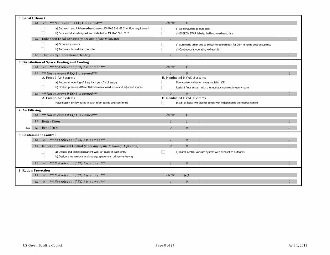
5. Local Exhaust
5.1 � *** Not relevant if EQ 1 is earned*** Prereq. Y
5.2 Enhanced Local Exhaust (meet one of the following) 1 1 0 0
5.3 Third-Party Performance Testing 1 1 0 0
6. Distribution of Space Heating and Cooling
6.1 � *** Not relevant if EQ 1 is earned*** Prereq. Y
6.2 *** Not relevant if EQ 1 is earned*** 1 0 0 0
A. Forced-Air Systems B. Nonducted HVAC Systems
6.3 *** Not relevant if EQ 1 is earned*** 2 0 0 0
A. Forced-Air Systems B. Nonducted HVAC Systems
7. Air Filtering
7.1 *** Not relevant if EQ 1 is earned*** Prereq. Y
7.2 Better Filters 1 1 0 0
OR 7.3 Best Filters 2 0 0 0
8. Contaminant Control
8.1 � *** Not relevant if EQ 1 is earned*** 1 0 0 0
8.2 Indoor Contaminant Control (meet any of the following, 1 pt each) 2 0 0 0
8.3 � *** Not relevant if EQ 1 is earned*** 1 0 0 0
9. Radon Protection
9.1 � *** Not relevant if EQ 1 is earned*** Prereq. N/A
9.2 � *** Not relevant if EQ 1 is earned*** 1 0 0 0
a) Bathroom and kitchen exhaust meets ASHRAE Std. 62.2 air flow requirement c) Air exhausted to outdoors
b) Fans and ducts designed and installed to ASHRAE Std. 62.2 d) ENERGY STAR labeled bathroom exhaust fans
a) Occupancy sensor c) Automatic timer tied to switch to operate fan for 20+ minutes post-occupancy
b) Automatic humidistat controller d) Continuously operating exhaust fan
b) Limited pressure differential between closed room and adjacent spaces
a) Return air opening of 1 sq. inch per cfm of supply Flow control valves on every radiator; OR
Have supply air flow rates in each room tested and confirmed Install at least two distinct zones with independent thermostat control
a) Design and install permanent walk-off mats at each entry c) Install central vacuum system with exhaust to outdoors
b) Design shoe removal and storage space near primary entryway
Radiant floor system with thermostatic controls in every room
US Green Building Council Page 8 of 24 April 1, 2011
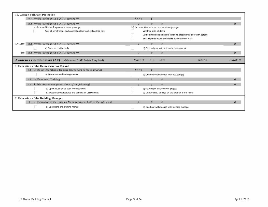
10. Garage Pollutant Protection
10.1 *** Not relevant if EQ 1 is earned*** Prereq. Y
10.2 *** Not relevant if EQ 1 is earned*** 2 0 0 0
a) In conditioned spaces above garage: b) In conditioned spaces next to garage
AND/OR 10.3 *** Not relevant if EQ 1 is earned*** 1 0 0 0
OR 10.4 *** Not relevant if EQ 1 is earned*** 3 0 0 0
Awareness & Education (AE) (Minimum 0 AE Points Required) Max: 3 Y:2 M:0 Final: 0
1. Education of the Homeowner or Tenant 2 0 0
1.1 � Basic Operations Training (meet both of the following) Prereq. Y
1.2 � Enhanced Training 1 1 0 0
1.3 Public Awareness (meet three of the following) 1 1 0 0
2. Education of the Building Manager
2 � Education of the Building Manager (meet both of the following) 1 0 0 0
Notes
Seal all penetrations and connecting floor and ceiling joist bays Weather-strip all doors
Carbon monoxide detectors in rooms that share a door with garage
Seal all penetrations and cracks at the base of walls
a) Fan runs continuously b) Fan designed with automatic timer control
a) Operations and training manual b) One-hour walkthrough with occupant(s)
b) Website about features and benefits of LEED homes
c) Newspaper article on the projecta) Open house on at least four weekends
d) Display LEED signage on the exterior of the home
a) Operations and training manual b) One-hour walkthrough with building manager
US Green Building Council Page 9 of 24 April 1, 2011
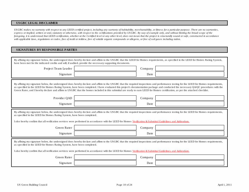
Project Team Leader Company
Signature Date
Provider QAD Company
Signature Date
Green Rater Company
Signature Date
Green Rater Company
Signature Date
By affixing my signature below, the undersigned does hereby declare and affirm to the USGBC that the required inspections and performance testing for the LEED for Homes requirements,
as specified in the LEED for Homes Rating System, have been completed. I have evaluated this project's documentation package and conducted the necessary QA/QC procedures with the
Green Rater, and I hereby declare and affirm to USGBC that the homes included in this submittal are ready to earn LEED for Homes certification, as per the attached checklist.
By affixing my signature below, the undersigned does hereby declare and affirm to the USGBC that the required inspections and performance testing for the LEED for Homes requirements,
as specified in the LEED for Homes Rating System, have been completed.
I also hereby confirm that all verification services were performed in accordance with the LEED for Homes Verification & Submittal Guidelines and Addendum.
USGBC makes no warranty with respect to any LEED certified project, including any warranty of habitability, merchantability, or fitness for a particular purpose. There are no warranties,
express or implied, written or oral, statutory or otherwise, with respect to the certifications provided by USGBC. By way of example only, and without limiting the broad scope of the
foregoing, it is understood that LEED certification, whether at the Certified level or any other level, does not mean that the project is structurally sound or safe, constructed in accordance
with applicable laws, regulations or codes, free of mold or mildew, free of volatile organic compounds or allegens, or free of soil gases including radon.
SIGNATURES BY RESPONSIBLE PARTIES
By affixing my signature below, the undersigned does hereby declare and affirm to the USGBC that the required inspections and performance testing for the LEED for Homes requirements,
as specified in the LEED for Homes Rating System, have been completed.
I also hereby confirm that all verification services were performed in accordance with the LEED for Homes Verification & Submittal Guidelines and Addendum.
USGBC LEGAL DISCLAIMER
By affixing my signature below, the undersigned does hereby declare and affirm to the USGBC that the LEED for Homes requirements, as specified in the LEED for Homes Rating System,
have been met for the indicated credits and will, if audited, provide the necessary supporting documents.
US Green Building Council Page 10 of 24 April 1, 2011

ENERGY STAR Qualified Homes, Version 3 (Rev. 06) National Program Requirements
Effective for homes permitted15 starting 11/10/2012 Revised 9/10/2012 Page 1 of 7
Qualifying Homes The following homes are eligible to earn the ENERGY STAR:
• Detached dwelling units 1 (e.g. single family homes); OR • Dwelling units 1 in any multifamily building with 4 units or fewer; OR • Dwelling units 1 in multifamily buildings with 3 stories or fewer above-grade2,3; OR • Dwelling units 1 in multifamily buildings with 4 or 5 stories above-grade2,3 that have their own heating, cooling, and hot water
systems4, separate from other units, and where dwelling units occupy 80% or more of the occupiable3 square footage of the building5. When evaluating mixed–use buildings for eligibility, exclude commercial / retail space when assessing whether the 80% threshold has been met.
Dwelling units 1 in multifamily buildings that are not eligible to earn the ENERGY STAR through the New Homes Program may be eligible through the Multifamily High Rise Program. Homes may earn the ENERGY STAR using the following ENERGY STAR Prescriptive Path or Performance Path in all states except those for which regional program requirements have been developed. See EPA’s Web site for the latest list. Note that compliance with these guidelines is not intended to imply compliance with all local code requirements that may be applicable to the home to be built.6 ENERGY STAR Prescriptive Path The Prescriptive Path provides a single set of measures that can be used to construct an ENERGY STAR qualified home. Modeling is not required; however, no tradeoffs are allowed. Follow these steps to use the Prescriptive Path:
1. First, assess the eligibility to follow the Prescriptive Path by comparing the conditioned floor area (CFA) of the home to be built to the CFA of the Benchmark Home as specified in Exhibit 3.7 For the purposes of this step, calculate the number of bedrooms and the CFA of the home to be built using RESNET standards with the following exception: floor area in basements with at least half of the gross surface area of the basement’s exterior walls below grade shall not be counted.8 If the CFA of the home to be built exceeds the CFA of the Benchmark Home, then the Performance Path shall be used.
2. If the home to be built is eligible to follow the Prescriptive Path, build the home using all requirements of the ENERGY STAR Reference Design, Exhibit 1, and the Mandatory Requirements for All Qualified Homes, Exhibit 2.
3. Using a Rater, verify that all requirements have been met in accordance with the Mandatory Requirements for All Qualified Homes and with RESNET’s On-Site Inspection Procedures for Minimum Rated Features.9
ENERGY STAR Performance Path The Performance Path provides flexibility to select a custom combination of measures for each home that is equivalent in performance to the minimum requirements of the ENERGY STAR Reference Design Home, Exhibit 1.10 Equivalent performance is assessed through energy modeling. Follow the steps below to use the Performance Path:
1. Determine the ENERGY STAR HERS Index Target, which is the highest numerical HERS Index value that each rated home may achieve to earn the ENERGY STAR. This target shall be specifically determined for each rated home by following the steps outlined in the ENERGY STAR HERS Index Target Procedure, Version 3 (Rev. 06), available on EPA’s Website. This procedure defines how to configure the ENERGY STAR Reference Design Home and calculate its associated HERS Index value and then how to apply the Size Adjustment Factor to determine the ENERGY STAR HERS Index Target. Note that this process shall be completed manually by a Rater until a version of the RESNET-accredited software program used by the Rater becomes available that automatically configures the ENERGY STAR Reference Design, calculates its associated HERS Index value, and then applies the Size Adjustment Factor to determine the ENERGY STAR HERS Index Target. Upon release of such a version, Raters using that software program shall have 60 days to begin all new ratings with this version.
2. Using the same RESNET-accredited Home Energy Rating software program, configure the preferred set of energy measures for the rated home and verify that the resulting HERS Index meets or exceeds the ENERGY STAR HERS Index Target, as determined in Step 1. Note that, regardless of the measures selected, Mandatory Requirements for All Qualified Homes in Exhibit 2 are also required. Also note that Items 1.2 and 2.1 of the Thermal Enclosure System Rater checklist require that all insulation, windows, doors, and skylights meet or exceed 2009 IECC requirements.11,12,13,14 Furthermore, on-site power generation may only be used to meet the ENERGY STAR HERS Index Target for homes that are larger than the Benchmark Home and only for the incremental change in ENERGY STAR HERS Index Target caused by the Size Adjustment Factor, as outlined in the ENERGY STAR HERS Index Target Procedure, Version 3 (Rev. 06).
3. Construct the home using measures selected in Step 2 and the Mandatory Requirements for All Qualified Homes, Exhibit 2. 4. Using a Rater, verify that all requirements have been met in accordance with the Mandatory Requirements for All Qualified
Homes and with RESNET’s On-Site Inspection Procedures for Minimum Rated Features.9 Partnership, Training, and Credentialing Requirements Builders, Raters, and HVAC contractors must meet the following requirements prior to qualifying homes under these guidelines:
• Builders are required to be ENERGY STAR partners and complete the online Version 3 Builder Orientation. Partnership Agreements and Version 3 Builder Orientation can be found at www.energystar.gov/homesPA.
• HVAC contractors must be credentialed by an EPA-recognized HVAC Quality Installation Training and Oversight Organization (H-QUITO). An explanation of this process and links to H-QUITOs can be found at www.energystar.gov/newhomesHVAC.
• Raters and Field Inspectors are required to complete Version 3 Training which can be found at www.energystar.gov/newhomestraining.
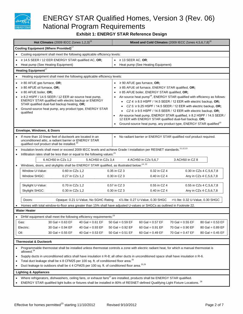
ENERGY STAR Qualified Homes, Version 3 (Rev. 06) National Program Requirements
Effective for homes permitted15 starting 11/10/2012 Revised 9/10/2012 Page 2 of 7
Exhibit 1: ENERGY STAR Reference Design
Hot Climates (2009 IECC Zones 1,2,3)16 Mixed and Cold Climates (2009 IECC Zones 4,5,6,7,8)16
Cooling Equipment (Where Provided)17
• Cooling equipment shall meet the following applicable efficiency levels:
• ≥ 14.5 SEER / 12 EER ENERGY STAR qualified AC, OR; • Heat pump (See Heating Equipment)
• ≥ 13 SEER AC, OR; • Heat pump (See Heating Equipment)
Heating Equipment17
• Heating equipment shall meet the following applicable efficiency levels:
• ≥ 80 AFUE gas furnace, OR; • ≥ 80 AFUE oil furnace, OR; • ≥ 80 AFUE boiler, OR; • ≥ 8.2 HSPF / 14.5 SEER / 12 EER air-source heat pump,
ENERGY STAR qualified with electric backup or ENERGY STAR qualified dual-fuel backup heating, OR;
• Ground-source heat pump, any product type, ENERGY STAR qualified
• ≥ 90 AFUE gas furnace, OR; • ≥ 85 AFUE oil furnace, ENERGY STAR qualified, OR; • ≥ 85 AFUE boiler, ENERGY STAR qualified, OR; • Air-source heat pump18, ENERGY STAR qualified with efficiency as follows:
• CZ 4: ≥ 8.5 HSPF / 14.5 SEER / 12 EER with electric backup, OR; • CZ 5: ≥ 9.25 HSPF / 14.5 SEER / 12 EER with electric backup, OR; • CZ 6: ≥ 9.5 HSPF / 14.5 SEER / 12 EER with electric backup, OR;
• Air-source heat pump, ENERGY STAR qualified, ≥ 8.2 HSPF / 14.5 SEER / 12 EER with ENERGY STAR qualified dual-fuel backup, OR;
• Ground-source heat pump, any product type, ENERGY STAR qualified19
Envelope, Windows, & Doors
• If more than 10 linear feet of ductwork are located in an unconditioned attic, a radiant barrier or ENERGY STAR qualified roof product shall be installed.20
• No radiant barrier or ENERGY STAR qualified roof product required.
• Insulation levels shall meet or exceed 2009 IECC levels and achieve Grade I installation per RESNET standards.11,12,13 • Infiltration rates shall be less than or equal to the following values:21
6 ACH50 in CZs 1,2 5 ACH50 in CZs 3,4 4 ACH50 in CZs 5,6,7 3 ACH50 in CZ 8
• Windows, doors, and skylights shall be ENERGY STAR qualified, as illustrated below:14, 22
Window U-Value: 0.60 in CZs 1,2 0.35 in CZ 3 0.32 in CZ 4 0.30 in CZs 4 C,5,6,7,8 Window SHGC: 0.27 in CZs 1,2 0.30 in CZ 3 0.40 in CZ 4 Any in CZs 4 C,5,6,7,8
Skylight U-Value: 0.70 in CZs 1,2 0.57 in CZ 3 0.55 in CZ 4 0.55 in CZs 4 C,5,6,7,8 Skylight SHGC: 0.30 in CZs 1,2 0.30 in CZ 3 0.40 in CZ 4 Any in CZs 4 C,5,6,7,8
Doors: Opaque: 0.21 U-Value, No SGHC Rating ≤½ lite: 0.27 U-Value, 0.30 SHGC >½ lite: 0.32 U-Value, 0.30 SHGC
• Homes with total window-to-floor area greater than 15% shall have adjusted U-values or SHGCs as outlined in Footnote 22. Water Heater
• DHW equipment shall meet the following efficiency requirements:23
Gas: 30 Gal = 0.63 EF 40 Gal = 0.61 EF 50 Gal = 0.59 EF 60 Gal = 0.57 EF 70 Gal = 0.55 EF 80 Gal = 0.53 EF Electric: 30 Gal = 0.94 EF 40 Gal = 0.93 EF 50 Gal = 0.92 EF 60 Gal = 0.91 EF 70 Gal = 0.90 EF 80 Gal = 0.89 EF Oil: 30 Gal = 0.55 EF 40 Gal = 0.53 EF 50 Gal = 0.51 EF 60 Gal = 0.49 EF 70 Gal = 0.47 EF 80 Gal = 0.45 EF
Thermostat & Ductwork
• Programmable thermostat shall be installed unless thermostat controls a zone with electric radiant heat, for which a manual thermostat is allowed.24
• Supply ducts in unconditioned attics shall have insulation ≥ R-8; all other ducts in unconditioned space shall have insulation ≥ R-6. • Total duct leakage shall be ≤ 8 CFM25 per 100 sq. ft. of conditioned floor area.25 • Duct leakage to outdoors shall be ≤ 4 CFM25 per 100 sq. ft. of conditioned floor area.25,26
Lighting & Appliances
• Where refrigerators, dishwashers, ceiling fans, or exhaust fans27 are installed, products shall be ENERGY STAR qualified. • ENERGY STAR qualified light bulbs or fixtures shall be installed in 80% of RESNET-defined Qualifying Light Fixture Locations. 28
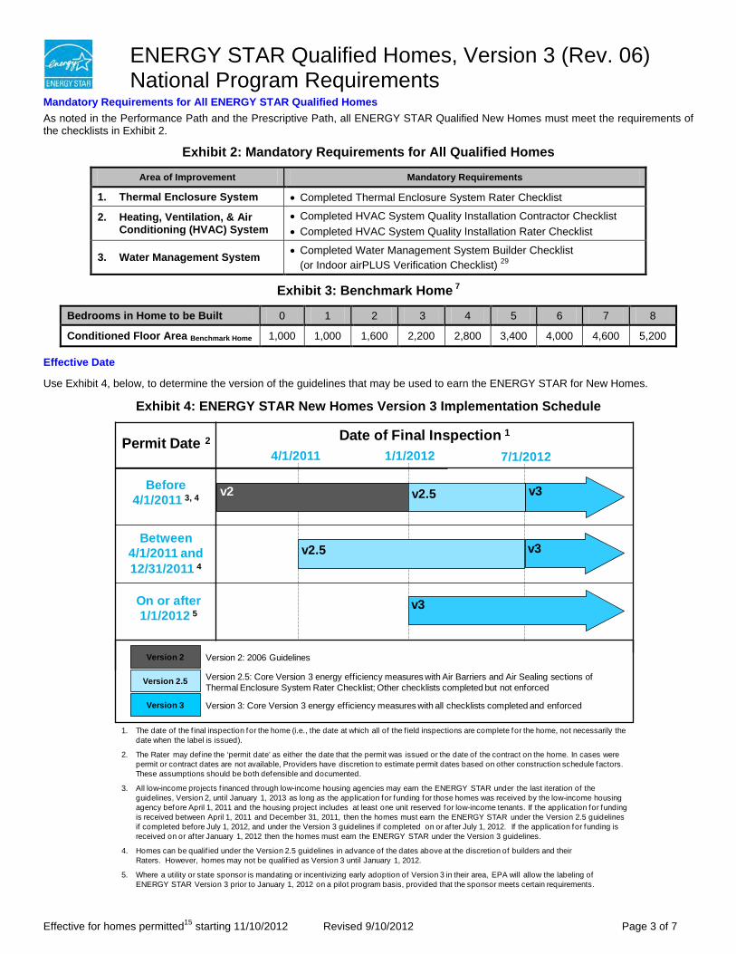
ENERGY STAR Qualified Homes, Version 3 (Rev. 06) National Program Requirements
Effective for homes permitted15 starting 11/10/2012 Revised 9/10/2012 Page 3 of 7
Mandatory Requirements for All ENERGY STAR Qualified Homes As noted in the Performance Path and the Prescriptive Path, all ENERGY STAR Qualified New Homes must meet the requirements of the checklists in Exhibit 2.
Exhibit 2: Mandatory Requirements for All Qualified Homes
Area of Improvement Mandatory Requirements
1. Thermal Enclosure System • Completed Thermal Enclosure System Rater Checklist
2. Heating, Ventilation, & Air Conditioning (HVAC) System
• Completed HVAC System Quality Installation Contractor Checklist • Completed HVAC System Quality Installation Rater Checklist
3. Water Management System • Completed Water Management System Builder Checklist (or Indoor airPLUS Verification Checklist) 29
Exhibit 3: Benchmark Home 7
Bedrooms in Home to be Built 0 1 2 3 4 5 6 7 8
Conditioned Floor Area Benchmark Home 1,000 1,000 1,600 2,200 2,800 3,400 4,000 4,600 5,200
Effective Date
Use Exhibit 4, below, to determine the version of the guidelines that may be used to earn the ENERGY STAR for New Homes.
Exhibit 4: ENERGY STAR New Homes Version 3 Implementation Schedule
1. The date of the f inal inspection for the home (i.e., the date at which all of the f ield inspections are complete for the home, not necessarily the date when the label is issued).
2. The Rater may def ine the ‘permit date’ as either the date that the permit was issued or the date of the contract on the home. In cases were permit or contract dates are not available, Providers have discretion to estimate permit dates based on other construction schedule factors. These assumptions should be both defensible and documented.
3. All low-income projects f inanced through low-income housing agencies may earn the ENERGY STAR under the last iteration of the guidelines, Version 2, until January 1, 2013 as long as the application for funding for those homes was received by the low-income housing agency before April 1, 2011 and the housing project includes at least one unit reserved for low-income tenants. If the application for funding is received between April 1, 2011 and December 31, 2011, then the homes must earn the ENERGY STAR under the Version 2.5 guidelines if completed before July 1, 2012, and under the Version 3 guidelines if completed on or af ter July 1, 2012. If the application for funding is received on or af ter January 1, 2012 then the homes must earn the ENERGY STAR under the Version 3 guidelines.
4. Homes can be qualif ied under the Version 2.5 guidelines in advance of the dates above at the discretion of builders and theirRaters. However, homes may not be qualif ied as Version 3 until January 1, 2012.
5. Where a utility or state sponsor is mandating or incentivizing early adoption of Version 3 in their area, EPA will allow the labeling of ENERGY STAR Version 3 prior to January 1, 2012 on a pilot program basis, provided that the sponsor meets certain requirements.
Permit Date 2
Before4/1/2011 3, 4
Between 4/1/2011 and 12/31/2011 4
On or after 1/1/2012 5
4/1/2011 1/1/2012Date of Final Inspection 1
Version 2: 2006 Guidelines
Version 2.5: Core Version 3 energy efficiency measures with Air Barriers and Air Sealing sections of Thermal Enclosure System Rater Checklist; Other checklists completed but not enforced
Version 3: Core Version 3 energy efficiency measures with all checklists completed and enforced
Version 2
Version 2.5
Version 3
v3
v2
v2.5
v3
7/1/2012
v3
v2.5
ENERGY STAR Qualified Homes, Version 3 (Rev. 06) National Program Requirements
Effective for homes permitted15 starting 11/10/2012 Revised 9/10/2012 Page 4 of 7
Notes (Unless specified otherwise, notes shall apply to both the Prescriptive Path and Performance Path): 1. A dwelling unit, as defined by the 2009 IECC, is a single unit that provides complete independent living facilities for one or more
persons, including permanent provisions for living, sleeping, eating, cooking, and sanitation. 2. Any above-grade story with 20% or more occupiable space, including commercial space, shall be counted towards the total
number of stories for the purpose of determining eligibility to participate in the program. The definition of an ‘above-grade story’ is one for which more than half of the gross surface area of the exterior walls is above-grade. All below-grade stories, regardless of type, shall not be included when evaluating eligibility.
3. Per ASHRAE 62.2-2010, occupiable space is any enclosed space inside the pressure boundary and intended for human activities or continual human occupancy, including, but not limited to, areas used for living, sleeping, dining, and cooking, toilets, closets, halls, storage and utility areas, and laundry areas.
4. Central systems for domestic hot water are allowed if solar energy provides at least 50% of the domestic hot water needs for the residential units.
5. Units in multifamily buildings with 4 or 5 stories above-grade, including mixed–use buildings, that have their own heating, cooling, and hot water systems, separate from other units, but where dwelling units occupy less than 80% of the residential (i.e., excluding commercial / retail space for mixed-use buildings) occupiable square footage of the building may qualify for the ENERGY STAR through either the New Homes Program or the Multifamily High Rise Program if permitted prior to July 1, 2012. Units in buildings of this type that are permitted after this date shall only be eligible to earn the ENERGY STAR through the Multifamily High Rise (MFHR) Program.
6. Where requirements of the local codes, manufacturers’ installation instructions, engineering documents, or regional ENERGY STAR programs overlap with the requirements of these guidelines, EPA offers the following guidance:
a. In cases where the overlapping requirements exceed the ENERGY STAR guidelines, these overlapping requirements shall be met;
b. In cases where overlapping requirements conflict with a requirement of these ENERGY STAR guidelines (e.g., slab insulation is prohibited to allow visual access for termite inspections), then the conflicting requirement within these guidelines shall not be met. Qualification shall only be allowed if the Rater has determined that no equivalent option is available that could meet the intent of the conflicting requirement of these ENERGY STAR guidelines (e.g., switching from exterior to interior slab edge insulation). Note that, under the Performance Path, a home must still meet its ENERGY STAR HERS Index Target. Therefore, other efficiency measures may be needed to compensate for the omission of the conflicting requirement.
7. The average-size home with a specific number of bedrooms is termed the “Benchmark Home”. The conditioned floor area of a Benchmark Home (CFA Benchmark Home) is determined by selecting the appropriate value from Exhibit 3. For homes with more than 8 bedrooms, the CFA Benchmark Home shall be determined by multiplying 600 sq. ft. times the total number of bedrooms and adding 400 sq. ft. Example: CFA Benchmark Home for a 10 bedroom home = (600 sq. ft. x 10) + 400 sq. ft. = 6,400 sq. ft. A bedroom is defined by RESNET as a room or space 70 sq. ft. or greater size, with egress window and closet, used or intended to be used for sleeping. A "den", "library", or "home office" with a closet, egress window, and 70 sq. ft. or greater size or other similar rooms shall count as a bedroom, but living rooms and foyers shall not. An egress window, as defined in 2009 IRC section R310, shall refer to any operable window that provides for a means of escape and access for rescue in the event of an emergency. The egress window definition has been summarized for convenience. The egress window shall:
• have a sill height of not more than 44 in. above the floor; AND • have a minimum net clear opening of 5.7 sq. ft.; AND • have a minimum net clear opening height of 24 in.; AND • have a minimum net clear opening width of 20 in.; AND • be operational from the inside of the room without the use of keys, tools or special knowledge.
8. To determine whether at least half of the basement wall area is below grade, use the gross surface area of the walls that are in contact with either the ground or ambient outdoor air, measured from the basement floor to the bottom of the basement ceiling framing (e.g., the bottom of the joists for the floor above). Note that the exception regarding the floor area in basements is only for the purpose of determining a home’s Benchmark Home Size, Size Adjustment Factor, and eligibility to use the Prescriptive Path. The full conditioned floor area, per RESNET’s standards, should be used when rating the home (e.g., determining compliance with duct leakage requirements).
9. The term ‘Rater’ refers to the person completing the third-party inspections required for qualification. This person shall: a) be a certified Home Energy Rater, Rating Field Inspector, BOP Inspector, or an equivalent designation as determined by a Verification Oversight Organization such as RESNET; and, b) have attended and successfully completed an EPA-recognized training class. See www.energystar.gov/newhomestraining.
10. For Performance Path: For a complete definition of the ENERGY STAR Reference Design to be used when determining the ENERGY STAR HERS Index Target under the Performance Path, see the document titled “ENERGY STAR HERS Index Target Procedure, Version 3 (Rev. 06)” located on EPA’s Web site.

ENERGY STAR Qualified Homes, Version 3 (Rev. 06) National Program Requirements
Effective for homes permitted15 starting 11/10/2012 Revised 9/10/2012 Page 5 of 7
11. Insulation levels in a home shall meet or exceed the component insulation requirements in the 2009 IECC - Table 402.1.1. The
following exceptions apply: a. Steel-frame ceilings, walls, and floors shall meet the insulation requirements of the 2009 IECC – Table 402.2.5. In CZ 1
and 2, the continuous insulation requirements in this table shall be permitted to be reduced to R-3 for steel-frame wall assemblies with studs spaced at 24 in. on center. This exception shall not apply if the alternative calculations in d) are used;
b. For ceilings with attic spaces, R-30 shall satisfy the requirement for R-38 and R-38 shall satisfy the requirement for R-49 wherever the full height of uncompressed insulation at the lower R-value extends over the wall top plate at the eaves. This exemption shall not apply if the alternative calculations in d) are used;
c. For ceilings without attic spaces, R-30 shall satisfy the requirement for any required value above R-30 if the design of the roof / ceiling assembly does not provide sufficient space for the required insulation value. This exemption shall be limited to 500 square ft. or 20% of the total insulated ceiling area, whichever is less. This exemption shall not apply if the alternative calculations in d) are used;
d. An alternative equivalent U-factor or total UA calculation may also be used to demonstrate compliance, as follows: An assembly with a U-factor equal or less than specified in 2009 IECC Table 402.1.3 complies. A total building thermal envelope UA that is less than or equal to the total UA resulting from the U-factors in Table 402.1.3 also complies. The insulation levels of all non-fenestration components (i.e., ceilings, walls, floors, and slabs) can be traded off using the UA approach under both the Prescriptive and the Performance Path. Note that fenestration products (i.e., windows, skylights, doors) shall not be included in this calculation. Also, note that while ceiling and slab insulation can be included in trade-off calculations, Items 4.1 through 4.3 of the Thermal Enclosure System Rater Checklist shall be met regardless of the UA tradeoffs calculated. The UA calculation shall be done using a method consistent with the ASHRAE Handbook of Fundamentals and shall include the thermal bridging effects of framing materials. The calculation for a steel-frame envelope assembly shall use the ASHRAE zone method or a method providing equivalent results, and not a series-parallel path calculation method.
12. Consistent with the 2009 IECC, slab edge insulation is only required for slab-on-grade floors with a floor surface less than 12 inches below grade. Slab insulation shall extend to the top of the slab to provide a complete thermal break. If the top edge of the insulation is installed between the exterior wall and the edge of the interior slab, it shall be permitted to be cut at a 45-degree angle away from the exterior wall.
13. Insulation shall be verified by a Rater to achieve Grade I installation as defined in the RESNET Standards, except for ceiling, wall, and floor assemblies with continuous rigid insulation sheathing. For such homes, Grade II installation is acceptable for the cavity insulation only if the rigid insulation sheathing meets or exceeds the following levels: R-3 in Climate Zones 1 to 4; R-5 in Zones 5 to 8.
14. For Prescriptive Path: All windows, doors, and skylights shall meet or exceed ENERGY STAR Program Requirements for Residential Windows, Doors, and Skylights – Version 5.0 as outlined at www.energystar.gov/windows. For Performance Path: All windows, doors and skylights shall meet or exceed the component U-factor and SHGC requirements specified in the 2009 IECC – Table 402.1.1. If no NFRC rating is noted on the window or in product literature (e.g., for site-built fenestration), select the U-factor and SHGC value from Tables 4 and 14, respectively, in 2005 ASHRAE Fundamentals, Chapter 31. Select the highest U-factor and SHGC value among the values listed for the known window characteristics (e.g., frame type, number of panes, glass color, and presence of low-e coating). Note that the U-factor requirement applies to all fenestration while the SHGC only applies to the glazed portion. The following exceptions apply:
a. An area-weighted average of fenestration products shall be permitted to satisfy the U-factor requirements; b. An area-weighted average of fenestration products more than 50% glazed shall be permitted to satisfy the SHGC
requirements; c. 15 square feet of glazed fenestration per dwelling unit shall be exempt from the U-factor and SHGC requirements, and
shall be excluded from area-weighted averages calculated using a) and b), above; d. One side-hinged opaque door assembly up to 24 square feet in area shall be exempt from the U-factor requirements and
shall be excluded from area-weighted averages calculated using a) and b), above; e. Fenestration utilized as part of a passive solar design shall be exempt from the U-factor and SHGC requirements, and
shall be excluded from area-weighted averages calculated using a) and b), above. Exempt windows shall be facing within 45 degrees of true South and directly coupled to thermal storage mass that has a heat capacity > 20 btu / ft3xoF and provided in a ratio of at least 3 sq. ft. per sq. ft. of South facing fenestration. Generally, thermal mass materials will be at least 2 in. thick.
15. The Rater may define the ‘permit date’ as either the date that the permit was issued or the date of the contract on the home. In cases where permit or contract dates are not available, Providers have discretion to estimate permit dates based on other construction schedule factors. These assumptions should be both defensible and documented.
16. The following Map is shown to depict Climate Zone boundaries. It is for illustrative purposes only and is based on 2009 IECC Figure 301.1.
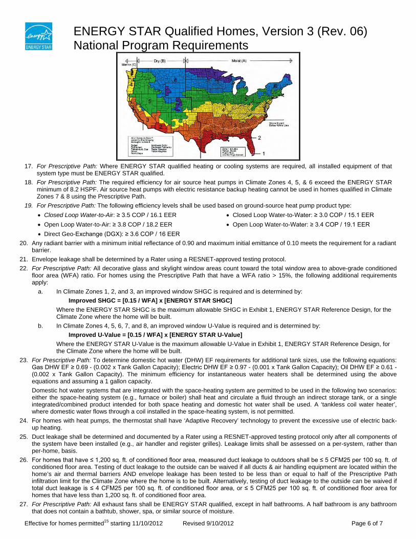
ENERGY STAR Qualified Homes, Version 3 (Rev. 06) National Program Requirements
Effective for homes permitted15 starting 11/10/2012 Revised 9/10/2012 Page 6 of 7
17. For Prescriptive Path: Where ENERGY STAR qualified heating or cooling systems are required, all installed equipment of that
system type must be ENERGY STAR qualified. 18. For Prescriptive Path: The required efficiency for air source heat pumps in Climate Zones 4, 5, & 6 exceed the ENERGY STAR
minimum of 8.2 HSPF. Air source heat pumps with electric resistance backup heating cannot be used in homes qualified in Climate Zones 7 & 8 using the Prescriptive Path.
19. For Prescriptive Path: The following efficiency levels shall be used based on ground-source heat pump product type: • Closed Loop Water-to-Air: ≥ 3.5 COP / 16.1 EER • Open Loop Water-to-Air: ≥ 3.8 COP / 18.2 EER • Direct Geo-Exchange (DGX): ≥ 3.6 COP / 16 EER
• Closed Loop Water-to-Water: ≥ 3.0 COP / 15.1 EER • Open Loop Water-to-Water: ≥ 3.4 COP / 19.1 EER
20. Any radiant barrier with a minimum initial reflectance of 0.90 and maximum initial emittance of 0.10 meets the requirement for a radiant barrier.
21. Envelope leakage shall be determined by a Rater using a RESNET-approved testing protocol. 22. For Prescriptive Path: All decorative glass and skylight window areas count toward the total window area to above-grade conditioned
floor area (WFA) ratio. For homes using the Prescriptive Path that have a WFA ratio > 15%, the following additional requirements apply:
a. In Climate Zones 1, 2, and 3, an improved window SHGC is required and is determined by: Improved SHGC = [0.15 / WFA] x [ENERGY STAR SHGC]
Where the ENERGY STAR SHGC is the maximum allowable SHGC in Exhibit 1, ENERGY STAR Reference Design, for the Climate Zone where the home will be built.
b. In Climate Zones 4, 5, 6, 7, and 8, an improved window U-Value is required and is determined by: Improved U-Value = [0.15 / WFA] x [ENERGY STAR U-Value]
Where the ENERGY STAR U-Value is the maximum allowable U-Value in Exhibit 1, ENERGY STAR Reference Design, for the Climate Zone where the home will be built.
23. For Prescriptive Path: To determine domestic hot water (DHW) EF requirements for additional tank sizes, use the following equations: Gas DHW EF ≥ 0.69 - (0.002 x Tank Gallon Capacity); Electric DHW EF ≥ 0.97 - (0.001 x Tank Gallon Capacity); Oil DHW EF ≥ 0.61 - (0.002 x Tank Gallon Capacity). The minimum efficiency for instantaneous water heaters shall be determined using the above equations and assuming a 1 gallon capacity. Domestic hot water systems that are integrated with the space-heating system are permitted to be used in the following two scenarios: either the space-heating system (e.g., furnace or boiler) shall heat and circulate a fluid through an indirect storage tank, or a single integrated/combined product intended for both space heating and domestic hot water shall be used. A ‘tankless coil water heater’, where domestic water flows through a coil installed in the space-heating system, is not permitted.
24. For homes with heat pumps, the thermostat shall have ‘Adaptive Recovery’ technology to prevent the excessive use of electric back-up heating.
25. Duct leakage shall be determined and documented by a Rater using a RESNET-approved testing protocol only after all components of the system have been installed (e.g., air handler and register grilles). Leakage limits shall be assessed on a per-system, rather than per-home, basis.
26. For homes that have ≤ 1,200 sq. ft. of conditioned floor area, measured duct leakage to outdoors shall be ≤ 5 CFM25 per 100 sq. ft. of conditioned floor area. Testing of duct leakage to the outside can be waived if all ducts & air handling equipment are located within the home’s air and thermal barriers AND envelope leakage has been tested to be less than or equal to half of the Prescriptive Path infiltration limit for the Climate Zone where the home is to be built. Alternatively, testing of duct leakage to the outside can be waived if total duct leakage is ≤ 4 CFM25 per 100 sq. ft. of conditioned floor area, or ≤ 5 CFM25 per 100 sq. ft. of conditioned floor area for homes that have less than 1,200 sq. ft. of conditioned floor area.
27. For Prescriptive Path: All exhaust fans shall be ENERGY STAR qualified, except in half bathrooms. A half bathroom is any bathroom that does not contain a bathtub, shower, spa, or similar source of moisture.
ENERGY STAR Qualified Homes, Version 3 (Rev. 06) National Program Requirements
Effective for homes permitted15 starting 11/10/2012 Revised 9/10/2012 Page 7 of 7
28. For Prescriptive Path: The ENERGY STAR Advanced Lighting Package (ALP), which requires a minimum of 60% ENERGY STAR
qualified hard-wired fixtures and 100% ENERGY STAR qualified ceiling fans, where installed, may also be used to comply with the lighting requirements.
29. A completed and signed Indoor airPLUS Verification Checklist may be submitted in lieu of the Water Management System Builder Checklist. Indoor airPLUS is a complimentary EPA label recognizing new homes equipped with a comprehensive set of Indoor Air Quality (IAQ) features. Indoor airPLUS verification can be completed by a Rater during the ENERGY STAR verification process. For more information, see www.epa.gov/indoorairplus.
ENERGY STAR Qualified Homes, Version 3 (Rev. 06) Inspection Checklists for National Program Requirements
As described in the ENERGY STAR Qualified Homes National Program Requirements, Version 3 (Rev. 06), one prerequisite for qualification is that a home must meet the requirements of the four attached checklists: Thermal Enclosure System Rater Checklist HVAC System Quality Installation Contractor Checklist HVAC System Quality Installation Rater Checklist Water Management System Builder Checklist (or Indoor airPLUS Verification Checklist) 1
To be eligible for qualification, a home must also meet the other requirements listed in the National Program Requirements document, including verification of all requirements by a Rater. 2 Note that compliance with these guidelines is not intended to imply compliance with all local code requirements that may be applicable to the home to be built. Where requirements of the local codes, manufacturers’ installation instructions, engineering documents, or regional ENERGY STAR programs overlap with the requirements of these guidelines, EPA offers the following guidance:
a. In cases where the overlapping requirements exceed the ENERGY STAR guidelines, these overlapping requirements shall be met;
b. In cases where overlapping requirements conflict with a requirement of these ENERGY STAR guidelines (e.g., slab insulation is prohibited to allow visual access for termite inspections), then the conflicting requirement within these guidelines shall not be met. Qualification shall only be allowed if the Rater has determined that no equivalent option is available that could meet the intent of the conflicting requirement of these ENERGY STAR guidelines (e.g., switching from exterior to interior slab edge insulation). Note that, under the Performance Path, a home must still meet its ENERGY STAR HERS Index Target (or equivalent target for regional program requirements). Therefore, other efficiency measures may be needed to compensate for the omission of the conflicting requirement.
The Rater must review all items on the Rater checklists. Raters are expected to use their experience and discretion to verify that the overall intent of each inspection checklist item has been met (i.e., identifying major defects that undermine the intent of the checklist item versus identifying minor defects that the Rater may deem acceptable). The column titled “N/A,” which denotes items that are “not applicable,” should be used when the checklist item is not present in the home or conflicts with local requirements. In the event that a Rater finds an item that is inconsistent with the intent of the inspection checklists, the home cannot earn the ENERGY STAR until the item is corrected. If correction of the item is not possible, the home cannot earn the ENERGY STAR. In the event that an item on a Rater checklist cannot be inspected by the Rater, the home also cannot earn the ENERGY STAR. The only exceptions to this rule are in the Thermal Enclosure System Rater Checklist, where the builder may assume responsibility for verifying a maximum of eight items. This option shall only be used at the discretion of the Rater. When exercised, the builder’s responsibility will be formally acknowledged by the builder signing off on the checklist for the item(s) that they verified. In the event that a Rater is not able to determine whether an item is consistent with the intent (e.g., an alternative method of meeting a checklist requirement has been proposed), then the Rater shall consult their Provider. If the Provider also cannot make this determination, then the Rater or Provider shall report the issue to EPA prior to project completion at: [email protected] and will typically receive an initial response within 5 business days. If EPA believes the current program guidelines are sufficiently clear to determine whether the intent has been met, then this guidance will be provided to the partner and enforced beginning with the house in question. In contrast, if EPA believes the program guidelines require revisions to make the intent clear, then this guidance will be provided to the partner but only enforced for homes permitted after a specified transition period after the release of the revised guidelines, typically 60 days in length. This process will allow EPA to make formal policy decisions as partner questions arise and to disseminate these policy decisions through the periodic release of revised program documents to ensure consistent application of the program guidelines. The Rater is required to keep electronic or hard copies of the completed and signed checklists. Raters who operate under a Sampling Provider are permitted to use the RESNET-approved sampling protocol for homes located outside California, and the CEC-approved sampling protocol for homes located in CA, to verify any item designated “Rater Verified”. No parties other than Raters are permitted to use sampling. All other items shall be verified for each certified home. For example, no items on the HVAC System QI Contractor Checklist are permitted to be verified using a sampling protocol because they may only be designated as “Builder Verified” or “Contractor Verified”. As another example, if a Rater verifies 10 items on the Water Management System Builder Checklist and the builder verifies the remaining checklist items, then the applicable (either RESNET or CEC) sampling protocol is permitted to be used only on the 10 Rater-verified items.
Rater Name: ___________________________________________________ Rater has verified that builder is an
Rater Company Name: __________________________________________ ENERGY STAR partner
Builder Company Name: _________________________________________
Effective for homes permitted 3 starting 11/10/2012 Revised 9/10/2012 Page 1 of 16
ENERGY STAR Qualified Homes, Version 3 (Rev. 06) Inspection Checklist Notes
1. A completed and signed Indoor airPLUS Verification Checklist may be submitted in lieu of the Water Management System Builder Checklist. Indoor airPLUS is a complimentary EPA label recognizing new homes equipped with a comprehensive set of Indoor Air Quality (IAQ) features. Indoor airPLUS verification can be completed by a Rater during the ENERGY STAR verification process. For more information, see www.epa.gov/indoorairplus.
2. The term ‘Rater’ refers to the person completing the third-party inspections required for qualification. This person shall: a) be a certified Home Energy Rater, Rating Field Inspector, BOP Inspector, or an equivalent designation as determined by a Verification Oversight Organization such as RESNET; and, b) have attended and successfully completed an EPA-recognized training class. See www.energystar.gov/newhomestraining.
3. The Rater may define the ‘permit date’ as either the date that the permit was issued or the date of the contract on the home. In cases where permit or contract dates are not available, Providers have discretion to estimate permit dates based on other construction schedule factors. These assumptions should be both defensible and documented.
Effective for homes permitted 3 starting 11/10/2012 Revised 9/10/2012 Page 2 of 16
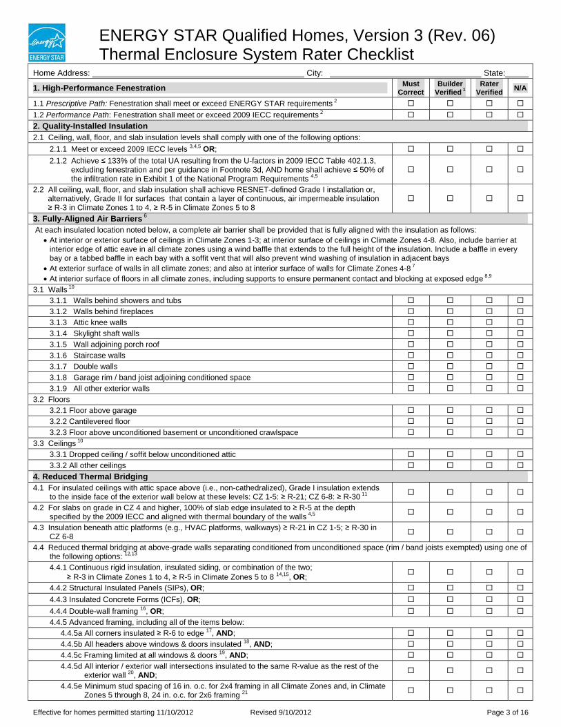
ENERGY STAR Qualified Homes, Version 3 (Rev. 06) Thermal Enclosure System Rater Checklist
Home Address: City: State:
1. High-Performance Fenestration Must Correct
Builder Verified 1
Rater Verified N/A
1.1 Prescriptive Path: Fenestration shall meet or exceed ENERGY STAR requirements 2
1.2 Performance Path: Fenestration shall meet or exceed 2009 IECC requirements 2
2. Quality-Installed Insulation 2.1 Ceiling, wall, floor, and slab insulation levels shall comply with one of the following options:
2.1.1 Meet or exceed 2009 IECC levels 3,4,5 OR;
2.1.2 Achieve ≤ 133% of the total UA resulting from the U-factors in 2009 IECC Table 402.1.3, excluding fenestration and per guidance in Footnote 3d, AND home shall achieve ≤ 50% of the infiltration rate in Exhibit 1 of the National Program Requirements 4,5
2.2 All ceiling, wall, floor, and slab insulation shall achieve RESNET-defined Grade I installation or, alternatively, Grade II for surfaces that contain a layer of continuous, air impermeable insulation ≥ R-3 in Climate Zones 1 to 4, ≥ R-5 in Climate Zones 5 to 8
3. Fully-Aligned Air Barriers 6
At each insulated location noted below, a complete air barrier shall be provided that is fully aligned with the insulation as follows: At interior or exterior surface of ceilings in Climate Zones 1-3; at interior surface of ceilings in Climate Zones 4-8. Also, include barrier at
interior edge of attic eave in all climate zones using a wind baffle that extends to the full height of the insulation. Include a baffle in every bay or a tabbed baffle in each bay with a soffit vent that will also prevent wind washing of insulation in adjacent bays At exterior surface of walls in all climate zones; and also at interior surface of walls for Climate Zones 4-8 7
At interior surface of floors in all climate zones, including supports to ensure permanent contact and blocking at exposed edge 8,9
3.1 Walls 10
3.1.1 Walls behind showers and tubs
3.1.2 Walls behind fireplaces
3.1.3 Attic knee walls
3.1.4 Skylight shaft walls
3.1.5 Wall adjoining porch roof
3.1.6 Staircase walls
3.1.7 Double walls
3.1.8 Garage rim / band joist adjoining conditioned space
3.1.9 All other exterior walls
3.2 Floors 3.2.1 Floor above garage
3.2.2 Cantilevered floor
3.2.3 Floor above unconditioned basement or unconditioned crawlspace
3.3 Ceilings 10
3.3.1 Dropped ceiling / soffit below unconditioned attic
3.3.2 All other ceilings
4. Reduced Thermal Bridging 4.1 For insulated ceilings with attic space above (i.e., non-cathedralized), Grade I insulation extends
to the inside face of the exterior wall below at these levels: CZ 1-5: ≥ R-21; CZ 6-8: ≥ R-30 11
4.2 For slabs on grade in CZ 4 and higher, 100% of slab edge insulated to ≥ R-5 at the depth specified by the 2009 IECC and aligned with thermal boundary of the walls 4,5
4.3 Insulation beneath attic platforms (e.g., HVAC platforms, walkways) ≥ R-21 in CZ 1-5; ≥ R-30 in CZ 6-8
4.4 Reduced thermal bridging at above-grade walls separating conditioned from unconditioned space (rim / band joists exempted) using one of the following options: 12,13
4.4.1 Continuous rigid insulation, insulated siding, or combination of the two; ≥ R-3 in Climate Zones 1 to 4, ≥ R-5 in Climate Zones 5 to 8 14,15, OR;
4.4.2 Structural Insulated Panels (SIPs), OR;
4.4.3 Insulated Concrete Forms (ICFs), OR;
4.4.4 Double-wall framing 16 , OR;
4.4.5 Advanced framing, including all of the items below: 4.4.5a All corners insulated ≥ R-6 to edge 17 , AND;
4.4.5b All headers above windows & doors insulated 18 , AND;
4.4.5c Framing limited at all windows & doors 19 , AND;
4.4.5d All interior / exterior wall intersections insulated to the same R-value as the rest of the exterior wall 20 , AND;
4.4.5e Minimum stud spacing of 16 in. o.c. for 2x4 framing in all Climate Zones and, in Climate Zones 5 through 8, 24 in. o.c. for 2x6 framing 21
Effective for homes permitted starting 11/10/2012 Revised 9/10/2012 Page 3 of 16
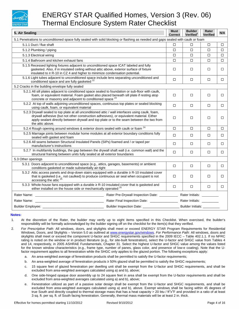
ENERGY STAR Qualified Homes, Version 3 (Rev. 06) Thermal Enclosure System Rater Checklist
5. Air Sealing Must Correct
Builder Verified1
Rater Verified N/A
5.1 Penetrations to unconditioned space fully sealed with solid blocking or flashing as needed and gaps sealed with caulk or foam 5.1.1 Duct / flue shaft
5.1.2 Plumbing / piping
5.1.3 Electrical wiring
5.1.4 Bathroom and kitchen exhaust fans
5.1.5 Recessed lighting fixtures adjacent to unconditioned space ICAT labeled and fully gasketed. Also, if in insulated ceiling without attic above, exterior surface of fixture insulated to ≥ R-10 in CZ 4 and higher to minimize condensation potential.
5.1.6 Light tubes adjacent to unconditioned space include lens separating unconditioned and conditioned space and are fully gasketed 22
5.2 Cracks in the building envelope fully sealed 5.2.1 All sill plates adjacent to conditioned space sealed to foundation or sub-floor with caulk,
foam, or equivalent material. Foam gasket also placed beneath sill plate if resting atop concrete or masonry and adjacent to conditioned space 23
5.2.2 At top of walls adjoining unconditioned spaces, continuous top plates or sealed blocking using caulk, foam, or equivalent material
5.2.3 Drywall sealed to top plate at all unconditioned attic / wall interfaces using caulk, foam, drywall adhesive (but not other construction adhesives), or equivalent material. Either apply sealant directly between drywall and top plate or to the seam between the two from the attic above.
5.2.4 Rough opening around windows & exterior doors sealed with caulk or foam 24
5.2.5 Marriage joints between modular home modules at all exterior boundary conditions fully sealed with gasket and foam
5.2.6 All seams between Structural Insulated Panels (SIPs) foamed and / or taped per manufacturer’s instructions
5.2.7 In multifamily buildings, the gap between the drywall shaft wall (i.e. common wall) and the structural framing between units fully sealed at all exterior boundaries
5.3 Other openings 5.3.1 Doors adjacent to unconditioned space (e.g., attics, garages, basements) or ambient
conditions gasketed or made substantially air-tight
5.3.2 Attic access panels and drop-down stairs equipped with a durable ≥ R-10 insulated cover that is gasketed (i.e., not caulked) to produce continuous air seal when occupant is not accessing the attic 25
5.3.3 Whole-house fans equipped with a durable ≥ R-10 insulated cover that is gasketed and either installed on the house side or mechanically operated 25
Rater Name: _____________________________________ Rater Pre-Drywall Inspection Date: __________ Rater Initials: _________
Rater Name: _____________________________________ Rater Final Inspection Date: _______________ Rater Initials: _________
Builder Employee: _________________________________ Builder Inspection Date: Builder Initials:
Notes: 1. At the discretion of the Rater, the builder may verify up to eight items specified in this Checklist. When exercised, the builder’s
responsibility will be formally acknowledged by the builder signing off on the checklist for the item(s) that they verified. 2. For Prescriptive Path: All windows, doors, and skylights shall meet or exceed ENERGY STAR Program Requirements for Residential
Windows, Doors, and Skylights – Version 5.0 as outlined at www.energystar.gov/windows. For Performance Path: All windows, doors and skylights shall meet or exceed the component U-factor and SHGC requirements specified in the 2009 IECC – Table 402.1.1. If no NFRC rating is noted on the window or in product literature (e.g., for site-built fenestration), select the U-factor and SHGC value from Tables 4 and 14, respectively, in 2005 ASHRAE Fundamentals, Chapter 31. Select the highest U-factor and SHGC value among the values listed for the known window characteristics (e.g., frame type, number of panes, glass color, and presence of low-e coating). Note that the U-factor requirement applies to all fenestration while the SHGC only applies to the glazed portion. The following exceptions apply:
a. An area-weighted average of fenestration products shall be permitted to satisfy the U-factor requirements; b. An area-weighted average of fenestration products ≥ 50% glazed shall be permitted to satisfy the SHGC requirements; c. 15 square feet of glazed fenestration per dwelling unit shall be exempt from the U-factor and SHGC requirements, and shall be
excluded from area-weighted averages calculated using a) and b), above; d. One side-hinged opaque door assembly up to 24 square feet in area shall be exempt from the U-factor requirements and shall be
excluded from area-weighted averages calculated using a) and b), above; e. Fenestration utilized as part of a passive solar design shall be exempt from the U-factor and SHGC requirements, and shall be
excluded from area-weighted averages calculated using a) and b), above. Exempt windows shall be facing within 45 degrees of true South and directly coupled to thermal storage mass that has a heat capacity > 20 btu / ft3xoF and provided in a ratio of at least 3 sq. ft. per sq. ft. of South facing fenestration. Generally, thermal mass materials will be at least 2 in. thick.
Effective for homes permitted starting 11/10/2012 Revised 9/10/2012 Page 4 of 16
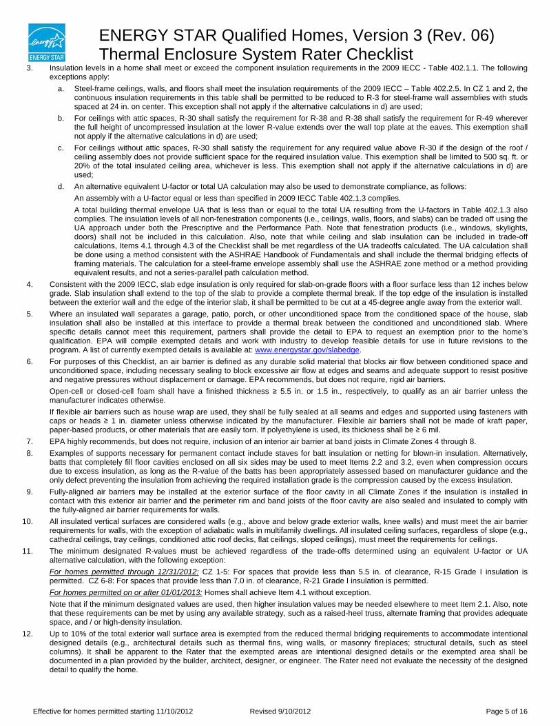
ENERGY STAR Qualified Homes, Version 3 (Rev. 06) Thermal Enclosure System Rater Checklist
3. Insulation levels in a home shall meet or exceed the component insulation requirements in the 2009 IECC - Table 402.1.1. The following exceptions apply:
a. Steel-frame ceilings, walls, and floors shall meet the insulation requirements of the 2009 IECC – Table 402.2.5. In CZ 1 and 2, the continuous insulation requirements in this table shall be permitted to be reduced to R-3 for steel-frame wall assemblies with studs spaced at 24 in. on center. This exception shall not apply if the alternative calculations in d) are used;
b. For ceilings with attic spaces, R-30 shall satisfy the requirement for R-38 and R-38 shall satisfy the requirement for R-49 wherever the full height of uncompressed insulation at the lower R-value extends over the wall top plate at the eaves. This exemption shall not apply if the alternative calculations in d) are used;
c. For ceilings without attic spaces, R-30 shall satisfy the requirement for any required value above R-30 if the design of the roof / ceiling assembly does not provide sufficient space for the required insulation value. This exemption shall be limited to 500 sq. ft. or 20% of the total insulated ceiling area, whichever is less. This exemption shall not apply if the alternative calculations in d) are used;
d. An alternative equivalent U-factor or total UA calculation may also be used to demonstrate compliance, as follows: An assembly with a U-factor equal or less than specified in 2009 IECC Table 402.1.3 complies. A total building thermal envelope UA that is less than or equal to the total UA resulting from the U-factors in Table 402.1.3 also complies. The insulation levels of all non-fenestration components (i.e., ceilings, walls, floors, and slabs) can be traded off using the UA approach under both the Prescriptive and the Performance Path. Note that fenestration products (i.e., windows, skylights, doors) shall not be included in this calculation. Also, note that while ceiling and slab insulation can be included in trade-off calculations, Items 4.1 through 4.3 of the Checklist shall be met regardless of the UA tradeoffs calculated. The UA calculation shall be done using a method consistent with the ASHRAE Handbook of Fundamentals and shall include the thermal bridging effects of framing materials. The calculation for a steel-frame envelope assembly shall use the ASHRAE zone method or a method providing equivalent results, and not a series-parallel path calculation method.
4. Consistent with the 2009 IECC, slab edge insulation is only required for slab-on-grade floors with a floor surface less than 12 inches below grade. Slab insulation shall extend to the top of the slab to provide a complete thermal break. If the top edge of the insulation is installed between the exterior wall and the edge of the interior slab, it shall be permitted to be cut at a 45-degree angle away from the exterior wall.
5. Where an insulated wall separates a garage, patio, porch, or other unconditioned space from the conditioned space of the house, slab insulation shall also be installed at this interface to provide a thermal break between the conditioned and unconditioned slab. Where specific details cannot meet this requirement, partners shall provide the detail to EPA to request an exemption prior to the home’s qualification. EPA will compile exempted details and work with industry to develop feasible details for use in future revisions to the program. A list of currently exempted details is available at: www.energystar.gov/slabedge.
6. For purposes of this Checklist, an air barrier is defined as any durable solid material that blocks air flow between conditioned space and unconditioned space, including necessary sealing to block excessive air flow at edges and seams and adequate support to resist positive and negative pressures without displacement or damage. EPA recommends, but does not require, rigid air barriers. Open-cell or closed-cell foam shall have a finished thickness ≥ 5.5 in. or 1.5 in., respectively, to qualify as an air barrier unless the manufacturer indicates otherwise. If flexible air barriers such as house wrap are used, they shall be fully sealed at all seams and edges and supported using fasteners with caps or heads ≥ 1 in. diameter unless otherwise indicated by the manufacturer. Flexible air barriers shall not be made of kraft paper, paper-based products, or other materials that are easily torn. If polyethylene is used, its thickness shall be ≥ 6 mil.
7. EPA highly recommends, but does not require, inclusion of an interior air barrier at band joists in Climate Zones 4 through 8. 8. Examples of supports necessary for permanent contact include staves for batt insulation or netting for blown-in insulation. Alternatively,
batts that completely fill floor cavities enclosed on all six sides may be used to meet Items 2.2 and 3.2, even when compression occurs due to excess insulation, as long as the R-value of the batts has been appropriately assessed based on manufacturer guidance and the only defect preventing the insulation from achieving the required installation grade is the compression caused by the excess insulation.
9. Fully-aligned air barriers may be installed at the exterior surface of the floor cavity in all Climate Zones if the insulation is installed in contact with this exterior air barrier and the perimeter rim and band joists of the floor cavity are also sealed and insulated to comply with the fully-aligned air barrier requirements for walls.
10. All insulated vertical surfaces are considered walls (e.g., above and below grade exterior walls, knee walls) and must meet the air barrier requirements for walls, with the exception of adiabatic walls in multifamily dwellings. All insulated ceiling surfaces, regardless of slope (e.g., cathedral ceilings, tray ceilings, conditioned attic roof decks, flat ceilings, sloped ceilings), must meet the requirements for ceilings.
11. The minimum designated R-values must be achieved regardless of the trade-offs determined using an equivalent U-factor or UA alternative calculation, with the following exception: For homes permitted through 12/31/2012: CZ 1-5: For spaces that provide less than 5.5 in. of clearance, R-15 Grade I insulation is permitted. CZ 6-8: For spaces that provide less than 7.0 in. of clearance, R-21 Grade I insulation is permitted. For homes permitted on or after 01/01/2013: Homes shall achieve Item 4.1 without exception. Note that if the minimum designated values are used, then higher insulation values may be needed elsewhere to meet Item 2.1. Also, note that these requirements can be met by using any available strategy, such as a raised-heel truss, alternate framing that provides adequate space, and / or high-density insulation.
12. Up to 10% of the total exterior wall surface area is exempted from the reduced thermal bridging requirements to accommodate intentional designed details (e.g., architectural details such as thermal fins, wing walls, or masonry fireplaces; structural details, such as steel columns). It shall be apparent to the Rater that the exempted areas are intentional designed details or the exempted area shall be documented in a plan provided by the builder, architect, designer, or engineer. The Rater need not evaluate the necessity of the designed detail to qualify the home.
Effective for homes permitted starting 11/10/2012 Revised 9/10/2012 Page 5 of 16
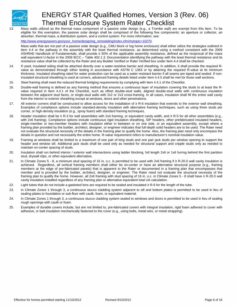
ENERGY STAR Qualified Homes, Version 3 (Rev. 06) Thermal Enclosure System Rater Checklist
13. Mass walls utilized as the thermal mass component of a passive solar design (e.g., a Trombe wall) are exempt from this item. To be eligible for this exemption, the passive solar design shall be comprised of the following five components: an aperture or collector, an absorber, thermal mass, a distribution system, and a control system. For more information, see: http://www.energysavers.gov/your_home/designing_remodeling/index.cfm/mytopic=10270. Mass walls that are not part of a passive solar design (e.g., CMU block or log home enclosure) shall either utilize the strategies outlined in Item 4.4 or the pathway in the assembly with the least thermal resistance, as determined using a method consistent with the 2009 ASHRAE Handbook of Fundamentals, shall provide ≥ 50% of the applicable assembly resistance, defined as the reciprocal of the mass wall equivalent U-factor in the 2009 IECC – Table 402.1.3. Documentation identifying the pathway with the least thermal resistance and its resistance value shall be collected by the Rater and any Builder Verified or Rater Verified box under Item 4.4 shall be checked.
14. If used, insulated siding shall be attached directly over a water-resistive barrier and sheathing. In addition, it shall provide the required R-value as demonstrated through either testing in accordance with ASTM C 1363 or by attaining the required R-value at its minimum thickness. Insulated sheathing rated for water protection can be used as a water resistant barrier if all seams are taped and sealed. If non-insulated structural sheathing is used at corners, advanced framing details listed under Item 4.4.5 shall be met for those wall sections.
15. Steel framing shall meet the reduced thermal bridging requirements by complying with Item 4.4.1 of the Checklist. 16. Double-wall framing is defined as any framing method that ensures a continuous layer of insulation covering the studs to at least the R-
value required in Item 4.4.1 of the Checklist, such as offset double-stud walls, aligned double-stud walls with continuous insulation between the adjacent stud faces, or single-stud walls with 2x2 or 2x3 cross-framing. In all cases, insulation shall fill the entire wall cavity from the interior to exterior sheathing except at windows, doors and other penetrations.
17. All exterior corners shall be constructed to allow access for the installation of ≥ R-6 insulation that extends to the exterior wall sheathing. Examples of compliance options include standard-density insulation with alternative framing techniques, such as using three studs per corner, or high-density insulation (e.g., spray foam) with standard framing techniques.
18. Header insulation shall be ≥ R-3 for wall assemblies with 2x4 framing, or equivalent cavity width, and ≥ R-5 for all other assemblies (e.g., with 2x6 framing). Compliance options include continuous rigid insulation sheathing, SIP headers, other prefabricated insulated headers, single-member or two-member headers with insulation either in between or on one side, or an equivalent assembly, except where a framing plan provided by the builder, architect, designer, or engineer indicates that full-depth solid headers are to be used. The Rater need not evaluate the structural necessity of the details in the framing plan to qualify the home. Also, the framing plan need only encompass the details in question and not necessarily the entire home. R-value requirement refers to manufacturer’s nominal insulation value.
19. Framing at windows shall be limited to a maximum of one pair of king studs and one pair jack studs per window opening to support the header and window sill. Additional jack studs shall be used only as needed for structural support and cripple studs only as needed to maintain on-center spacing of studs.
20. Insulation shall run behind interior / exterior wall intersections using ladder blocking, full length 2x6 or 1x6 furring behind the first partition stud, drywall clips, or other equivalent alternative.
21. In Climate Zones 5 - 8, a minimum stud spacing of 16 in. o.c. is permitted to be used with 2x6 framing if ≥ R-20.0 wall cavity insulation is achieved. Regardless, all vertical framing members shall either be on-center or have an alternative structural purpose (e.g., framing members at the edge of pre-fabricated panels) that is apparent to the Rater or documented in a framing plan that encompasses that member and is provided by the builder, architect, designer, or engineer. The Rater need not evaluate the structural necessity of the framing plan to qualify the home. However, all 2x6 framing with stud spacing of 16 in. o.c. in Climate Zones 5 - 8 shall have ≥ R-20.0 wall cavity insulation installed regardless of any framing plan or alternative equivalent total UA calculation.
22. Light tubes that do not include a gasketed lens are required to be sealed and insulated ≥ R-6 for the length of the tube. 23. In Climate Zones 1 through 3, a continuous stucco cladding system adjacent to sill and bottom plates is permitted to be used in lieu of
sealing plates to foundation or sub-floor with caulk, foam, or equivalent material. 24. In Climate Zones 1 through 3, a continuous stucco cladding system sealed to windows and doors is permitted to be used in lieu of sealing
rough openings with caulk or foam. 25. Examples of durable covers include, but are not limited to, pre-fabricated covers with integral insulation, rigid foam adhered to cover with
adhesive, or batt insulation mechanically fastened to the cover (e.g., using bolts, metal wire, or metal strapping).
Effective for homes permitted starting 11/10/2012 Revised 9/10/2012 Page 6 of 16
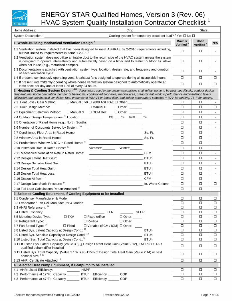
ENERGY STAR Qualified Homes, Version 3 (Rev. 06) HVAC System Quality Installation Contractor Checklist 1
Home Address: City: State:
System Description 2 Cooling system for temporary occupant load? 3 Yes No
1. Whole-Building Mechanical Ventilation Design 4 Builder Verified 5
Cont. Verified 6 N/A
1.1 Ventilation system installed that has been designed to meet ASHRAE 62.2-2010 requirements including, but not limited to, requirements in Items 1.2-1.5. 7 -
1.2 Ventilation system does not utilize an intake duct to the return side of the HVAC system unless the system is designed to operate intermittently and automatically based on a timer and to restrict outdoor air intake when not in use (e.g., motorized damper).
-
1.3 Documentation is attached with ventilation system type, location, design rate, and frequency and duration of each ventilation cycle. -
1.4 If present, continuously-operating vent. & exhaust fans designed to operate during all occupiable hours.
1.5 If present, intermittently-operating whole-house ventilation system designed to automatically operate at least once per day and at least 10% of every 24 hours.
2. Heating & Cooling System Design 4,8 - Parameters used in the design calculations shall reflect home to be built, specifically, outdoor design temperatures, home orientation, number of bedrooms, conditioned floor area, window area, predominant window performance and insulation levels, infiltration rate, mechanical ventilation rate, presence of MERV6 or better filter, and indoor temperature setpoints = 70°F for heating; 75°F for cooling.
2.1 Heat Loss / Gain Method: Manual J v8 2009 ASHRAE Other: ________ -2.2 Duct Design Method: Manual D Other: _______
2.3 Equipment Selection Method: Manual S OEM Rec. Other: _______ -2.4 Outdoor Design Temperatures: 9 Location: ____________ 1%: ___ °F 99%:___ °F -2.5 Orientation of Rated Home (e.g., North, South): _____________________________ -2.6 Number of Occupants Served by System: 10 _____________________________ -2.7 Conditioned Floor Area in Rated Home: _____________________________ Sq. Ft. -2.8 Window Area in Rated Home: _____________________________ Sq. Ft. -2.9 Predominant Window SHGC in Rated Home: 11 _____________________________ -2.10 Infiltration Rate in Rated Home: 12 Summer: _______ Winter:_______ -2.11 Mechanical Ventilation Rate in Rated Home: _____________________________ CFM -2.12 Design Latent Heat Gain: _____________________________ BTUh -2.13 Design Sensible Heat Gain: _____________________________ BTUh -2.14 Design Total Heat Gain: ____________________________ BTUh -2.15 Design Total Heat Loss: ____________________________ BTUh -2.16 Design Airflow: 13 _____________________________ CFM -2.17 Design Duct Static Pressure: 14 ____________________________ In. Water Column
2.18 Full Load Calculations Report Attached 15 -3. Selected Cooling Equipment, If Cooling Equipment to be Installed 3.1 Condenser Manufacturer & Model: ___________________________
3.2 Evaporator / Fan Coil Manufacturer & Model: ___________________________
3.3 AHRI Reference #: 16 ___________________________
3.4 Listed Efficiency: ______ EER _______ SEER
3.5 Metering Device Type: TXV Fixed orifice Other: _____
3.6 Refrigerant Type: R-410a Other: ____
3.7 Fan Speed Type: 17 Fixed Variable (ECM / ICM) Other: ____
3.8 Listed Sys. Latent Capacity at Design Cond.: 18 ____________________________ BTUh
3.9 Listed Sys. Sensible Capacity at Design Cond.:18 ___________________________ BTUh
3.10 Listed Sys. Total Capacity at Design Cond.:18 ____________________________ BTUh
3.11 If Listed Sys. Latent Capacity (Value 3.8) < Design Latent Heat Gain (Value 2.12), ENERGY STAR qualified dehumidifier installed
3.12 Listed Sys. Total Capacity (Value 3.10) is 95-115% of Design Total Heat Gain (Value 2.14) or next nominal size 8, 19
3.13 AHRI Certificate Attached 16
4. Selected Heat Pump Equipment, If Heatpump to be Installed 4.1 AHRI Listed Efficiency: _______ HSPF
4.2 Performance at 17°F: Capacity _______ BTUh Efficiency: ______ COP
4.3 Performance at 47°F: Capacity _______ BTUh Efficiency: ______ COP
Effective for homes permitted starting 11/10/2012 Revised 9/10/2012 Page 7 of 16
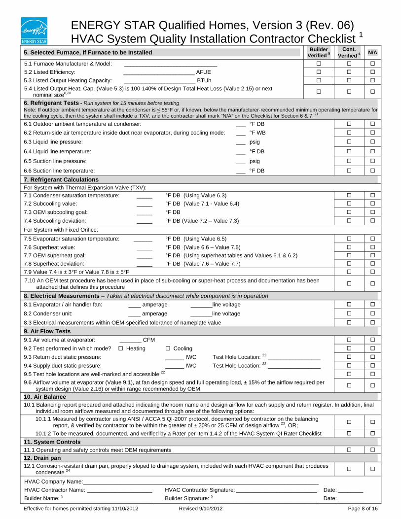
ENERGY STAR 4XDOLILHd Homes, Version 3 (Rev. 06) HVAC System Quality Installation Contractor Checklist 1
5. Selected Furnace, If Furnace to be Installed Builder Verified 5
Cont. Verified 6 N/A
5.1 Furnace Manufacturer & Model: ______________________________
5.2 Listed Efficiency: _______________________ AFUE
5.3 Listed Output Heating Capacity: _______________________ BTUh
5.4 Listed Output Heat. Cap. (Value 5.3) is 100-140% of Design Total Heat Loss (Value 2.15) or next nominal size8,20
6. Refrigerant Tests - Run system for 15 minutes before testing Note: If outdoor ambient temperature at the condenser is < 55°F or, if known, below the manufacturer-recommended minimum operating temperature for the cooling cycle, then the system shall include a TXV, and the contractor shall mark “N/A” on the Checklist for Section 6 & 7. 21
6.1 Outdoor ambient temperature at condenser: ___ °F DB
6.2 Return-side air temperature inside duct near evaporator, during cooling mode: ___ °F WB
6.3 Liquid line pressure: ___ psig
6.4 Liquid line temperature: ___ °F DB
6.5 Suction line pressure: ___ psig
6.6 Suction line temperature: ___ °F DB
7. Refrigerant Calculations For System with Thermal Expansion Valve (TXV): 7.1 Condenser saturation temperature: _____ °F DB (Using Value 6.3)
7.2 Subcooling value: _____ °F DB (Value 7.1 - Value 6.4)
7.3 OEM subcooling goal: _____ °F DB
7.4 Subcooling deviation: _____ °F DB (Value 7.2 – Value 7.3)
For System with Fixed Orifice: 7.5 Evaporator saturation temperature: ______ °F DB (Using Value 6.5)
7.6 Superheat value: _____ °F DB (Value 6.6 – Value 7.5)
7.7 OEM superheat goal: _____ °F DB (Using superheat tables and Values 6.1 & 6.2)
7.8 Superheat deviation: _____ °F DB (Value 7.6 – Value 7.7)
7.9 Value 7.4 is ± 3°F or Value 7.8 is ± 5°F
7.10 An OEM test procedure has been used in place of sub-cooling or super-heat process and documentation has been attached that defines this procedure
8. Electrical Measurements – Taken at electrical disconnect while component is in operation
8.1 Evaporator / air handler fan: ____ amperage _______line voltage
8.2 Condenser unit: ____ amperage _______line voltage
8.3 Electrical measurements within OEM-specified tolerance of nameplate value
9. Air Flow Tests 9.1 Air volume at evaporator: _______ CFM
9.2 Test performed in which mode? Heating Cooling
9.3 Return duct static pressure: ______ IWC Test Hole Location: 22 _________________
9.4 Supply duct static pressure: ______ IWC Test Hole Location: 22 _________________
9.5 Test hole locations are well-marked and accessible 22
9.6 Airflow volume at evaporator (Value 9.1), at fan design speed and full operating load, ± 15% of the airflow required per system design (Value 2.16) or within range recommended by OEM
10. Air Balance 10.1 Balancing report prepared and attached indicating the room name and design airflow for each supply and return register. In addition, final
individual room airflows measured and documented through one of the following options: 10.1.1 Measured by contractor using ANSI / ACCA 5 QI-2007 protocol, documented by contractor on the balancing
report, & verified by contractor to be within the greater of ± 20% or 25 CFM of design airflow 23, OR;
10.1.2 To be measured, documented, and verified by a Rater per Item 1.4.2 of the HVAC System QI Rater Checklist
11. System Controls 11.1 Operating and safety controls meet OEM requirements
12. Drain pan 12.1 Corrosion-resistant drain pan, properly sloped to drainage system, included with each HVAC component that produces
condensate 24
HVAC Company Name:____________________________________________________________________________ HVAC Contractor Name: _____________________ HVAC Contractor Signature: __________________________ Date: ________ Builder Name: 5 ____________________________ Builder Signature: 5 _________________________________ Date: ________
Effective for homes permitted starting 11/10/2012 Revised 9/10/2012 Page 8 of 16
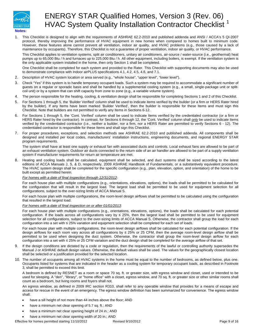
ENERGY STAR Qualified Homes, Version 3 (Rev. 06) HVAC System Quality Installation Contractor Checklist 1
Notes: 1. This Checklist is designed to align with the requirements of ASHRAE 62.2-2010 and published addenda and ANSI / ACCA’s 5 QI-2007
protocol, thereby improving the performance of HVAC equipment in new homes when compared to homes built to minimum code. However, these features alone cannot prevent all ventilation, indoor air quality, and HVAC problems (e.g., those caused by a lack of maintenance by occupants). Therefore, this Checklist is not a guarantee of proper ventilation, indoor air quality, or HVAC performance. This Checklist applies to ventilation systems, split air conditioners, unitary air conditioners, air-source / water-source (i.e., geothermal) heat pumps up to 65,000 Btu / h and furnaces up to 225,000 Btu / h. All other equipment, including boilers, is exempt. If the ventilation system is the only applicable system installed in the home, then only Section 1 shall be completed. One Checklist shall be completed for each system and provided to the Rater. This Checklist with supporting documents may also be used to demonstrate compliance with Indoor airPLUS specifications 4.1, 4.2, 4.5, 4.6, and 7.1.
2. Description of HVAC system location or area served (e.g., “whole house”, “upper level”, “lower level”). 3. Check “Yes” if this system is to handle temporary occupant loads. Such a system may be required to accommodate a significant number of
guests on a regular or sporadic basis and shall be handled by a supplemental cooling system (e.g., a small, single-package unit or split-coil unit) or by a system that can shift capacity from zone to zone (e.g., a variable volume system).
4. The person responsible for the heating, cooling, & ventilation design shall be responsible for completing Sections 1 and 2 of this Checklist. 5. For Sections 1 through 5, the ‘Builder Verified’ column shall be used to indicate items verified by the builder (or a firm or HERS Rater hired
by the builder). If any Items have been marked ‘Builder Verified’, then the builder is responsible for these Items and must sign this Checklist. Note that builders are not permitted to verify any Items in Sections 6-12.
6. For Sections 1 through 5, the ‘Cont. Verified’ column shall be used to indicate Items verified by the credentialed contractor (or a firm or HERS Rater hired by the contractor). In contrast, for Sections 6 through 12, the ‘Cont. Verified’ column shall only be used to indicate Items verified by the credentialed contractor (i.e., neither a builder, nor a firm, nor a HERS Rater are permitted to verify Sections 6 - 12). The credentialed contractor is responsible for these Items and shall sign this Checklist.
7. For proper procedures, exceptions, and selection methods see ASHRAE 62.2-2010 and published addenda. All components shall be designed and installed per local codes, manufacturers’ installation instructions, engineering documents, and regional ENERGY STAR program requirements. The system shall have at least one supply or exhaust fan with associated ducts and controls. Local exhaust fans are allowed to be part of an exhaust ventilation system. Outdoor air ducts connected to the return side of an air handler are allowed to be part of a supply ventilation system if manufacturer requirements for return air temperature are met.
8. Heating and cooling loads shall be calculated, equipment shall be selected, and duct systems shall be sized according to the latest editions of ACCA Manuals J, S, & D, respectively, 2009 ASHRAE Handbook of Fundamentals, or a substantively equivalent procedure. The HVAC system design shall be completed for the specific configuration (e.g., plan, elevation, option, and orientation) of the home to be built except as permitted herein. For homes with a date of final inspection through 12/31/2012: For each house plan with multiple configurations (e.g., orientations, elevations, options), the loads shall be permitted to be calculated for the configuration that will result in the largest load. The largest load shall be permitted to be used for equipment selection for all configurations, subject to the over-sizing limits of ACCA Manual S. For each house plan with multiple configurations, the room-level design airflows shall be permitted to be calculated using the configuration that resulted in the largest load. For homes with a date of final inspection on or after 01/01/2013: For each house plan with multiple configurations (e.g., orientations, elevations, options), the loads shall be calculated for each potential configuration. If the loads across all configurations vary by ≤ 25%, then the largest load shall be permitted to be used for equipment selection for all configurations, subject to the over-sizing limits of ACCA Manual S. Otherwise, the contractor shall group the load for each configuration into a set with ≤ 25% variation and equipment selection shall be completed for each set of loads. For each house plan with multiple configurations, the room-level design airflows shall be calculated for each potential configuration. If the design airflows for each room vary across all configurations by ≤ 25% or 25 CFM, then the average room-level design airflow shall be permitted to be used when designing the duct system. Otherwise, the contractor shall group the room-level design airflow for each configuration into a set with ≤ 25% or 25 CFM variation and the duct design shall be completed for the average airflow of that set.
9. If the design conditions are dictated by a code or regulation, then the requirements of the lawful or controlling authority supersedes the Manual J or ASHRAE default design values. Otherwise, the default values shall be used. The values for the geographically closest location shall be selected or a justification provided for the selected location.
10. The number of occupants among all HVAC systems in the home must be equal to the number of bedrooms, as defined below, plus one. Occupants listed for systems that are indicated in the header as a cooling system for temporary occupant loads, as described in Footnote 3, shall be permitted to exceed this limit. A bedroom is defined by RESNET as a room or space 70 sq. ft. or greater size, with egress window and closet, used or intended to be used for sleeping. A "den", "library", or "home office" with a closet, egress window, and 70 sq. ft. or greater size or other similar rooms shall count as a bedroom, but living rooms and foyers shall not. An egress window, as defined in 2009 IRC section R310, shall refer to any operable window that provides for a means of escape and access for rescue in the event of an emergency. The egress window definition has been summarized for convenience. The egress window shall: have a sill height of not more than 44 inches above the floor; AND have a minimum net clear opening of 5.7 sq. ft.; AND have a minimum net clear opening height of 24 in.; AND have a minimum net clear opening width of 20 in.; AND
Effective for homes permitted starting 11/10/2012 Revised 9/10/2012 Page 9 of 16
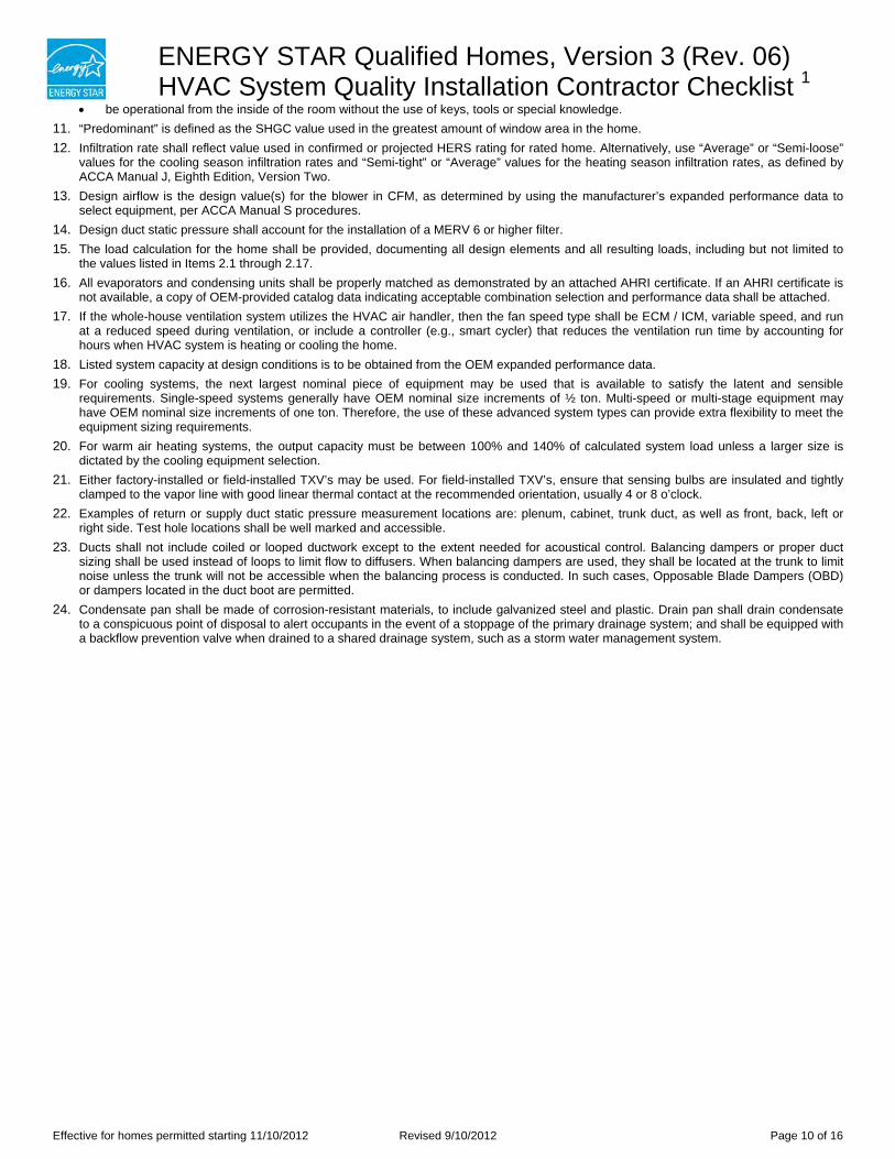
ENERGY STAR Qualified Homes, Version 3 (Rev. 06) HVAC System Quality Installation Contractor Checklist 1
be operational from the inside of the room without the use of keys, tools or special knowledge. 11. “Predominant” is defined as the SHGC value used in the greatest amount of window area in the home. 12. Infiltration rate shall reflect value used in confirmed or projected HERS rating for rated home. Alternatively, use “Average” or “Semi-loose”
values for the cooling season infiltration rates and “Semi-tight” or “Average” values for the heating season infiltration rates, as defined by ACCA Manual J, Eighth Edition, Version Two.
13. Design airflow is the design value(s) for the blower in CFM, as determined by using the manufacturer’s expanded performance data to select equipment, per ACCA Manual S procedures.
14. Design duct static pressure shall account for the installation of a MERV 6 or higher filter. 15. The load calculation for the home shall be provided, documenting all design elements and all resulting loads, including but not limited to
the values listed in Items 2.1 through 2.17. 16. All evaporators and condensing units shall be properly matched as demonstrated by an attached AHRI certificate. If an AHRI certificate is
not available, a copy of OEM-provided catalog data indicating acceptable combination selection and performance data shall be attached. 17. If the whole-house ventilation system utilizes the HVAC air handler, then the fan speed type shall be ECM / ICM, variable speed, and run
at a reduced speed during ventilation, or include a controller (e.g., smart cycler) that reduces the ventilation run time by accounting for hours when HVAC system is heating or cooling the home.
18. Listed system capacity at design conditions is to be obtained from the OEM expanded performance data. 19. For cooling systems, the next largest nominal piece of equipment may be used that is available to satisfy the latent and sensible
requirements. Single-speed systems generally have OEM nominal size increments of ½ ton. Multi-speed or multi-stage equipment may have OEM nominal size increments of one ton. Therefore, the use of these advanced system types can provide extra flexibility to meet the equipment sizing requirements.
20. For warm air heating systems, the output capacity must be between 100% and 140% of calculated system load unless a larger size is dictated by the cooling equipment selection.
21. Either factory-installed or field-installed TXV’s may be used. For field-installed TXV’s, ensure that sensing bulbs are insulated and tightly clamped to the vapor line with good linear thermal contact at the recommended orientation, usually 4 or 8 o’clock.
22. Examples of return or supply duct static pressure measurement locations are: plenum, cabinet, trunk duct, as well as front, back, left or right side. Test hole locations shall be well marked and accessible.
23. Ducts shall not include coiled or looped ductwork except to the extent needed for acoustical control. Balancing dampers or proper duct sizing shall be used instead of loops to limit flow to diffusers. When balancing dampers are used, they shall be located at the trunk to limit noise unless the trunk will not be accessible when the balancing process is conducted. In such cases, Opposable Blade Dampers (OBD) or dampers located in the duct boot are permitted.
24. Condensate pan shall be made of corrosion-resistant materials, to include galvanized steel and plastic. Drain pan shall drain condensate to a conspicuous point of disposal to alert occupants in the event of a stoppage of the primary drainage system; and shall be equipped with a backflow prevention valve when drained to a shared drainage system, such as a storm water management system.
Effective for homes permitted starting 11/10/2012 Revised 9/10/2012 Page 10 of 16
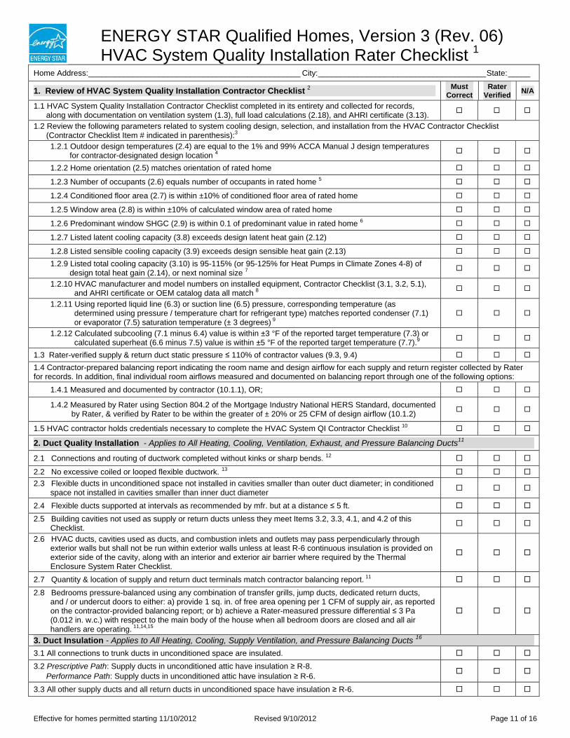
ENERGY STAR Qualified Homes, Version 3 (Rev. 06) HVAC System Quality Installation Rater Checklist 1
Home Address:________________________________________________ City: ______________________________________ State:_____
1. Review of HVAC System Quality Installation Contractor Checklist 2 Must Correct
Rater Verified N/A
1.1 HVAC System Quality Installation Contractor Checklist completed in its entirety and collected for records, along with documentation on ventilation system (1.3), full load calculations (2.18), and AHRI certificate (3.13).
1.2 Review the following parameters related to system cooling design, selection, and installation from the HVAC Contractor Checklist (Contractor Checklist Item # indicated in parenthesis):3
1.2.1 Outdoor design temperatures (2.4) are equal to the 1% and 99% ACCA Manual J design temperatures for contractor-designated design location 4
1.2.2 Home orientation (2.5) matches orientation of rated home
1.2.3 Number of occupants (2.6) equals number of occupants in rated home 5
1.2.4 Conditioned floor area (2.7) is within ±10% of conditioned floor area of rated home
1.2.5 Window area (2.8) is within ±10% of calculated window area of rated home
1.2.6 Predominant window SHGC (2.9) is within 0.1 of predominant value in rated home 6
1.2.7 Listed latent cooling capacity (3.8) exceeds design latent heat gain (2.12)
1.2.8 Listed sensible cooling capacity (3.9) exceeds design sensible heat gain (2.13)
1.2.9 Listed total cooling capacity (3.10) is 95-115% (or 95-125% for Heat Pumps in Climate Zones 4-8) of design total heat gain (2.14), or next nominal size 7
1.2.10 HVAC manufacturer and model numbers on installed equipment, Contractor Checklist (3.1, 3.2, 5.1), and AHRI certificate or OEM catalog data all match 8
1.2.11 Using reported liquid line (6.3) or suction line (6.5) pressure, corresponding temperature (as determined using pressure / temperature chart for refrigerant type) matches reported condenser (7.1) or evaporator (7.5) saturation temperature (± 3 degrees) 9
1.2.12 Calculated subcooling (7.1 minus 6.4) value is within ±3 °F of the reported target temperature (7.3) or calculated superheat (6.6 minus 7.5) value is within ±5 °F of the reported target temperature (7.7).9
1.3 Rater-verified supply & return duct static pressure ≤ 110% of contractor values (9.3, 9.4)
1.4 Contractor-prepared balancing report indicating the room name and design airflow for each supply and return register collected by Rater for records. In addition, final individual room airflows measured and documented on balancing report through one of the following options:
1.4.1 Measured and documented by contractor (10.1.1), OR;
1.4.2 Measured by Rater using Section 804.2 of the Mortgage Industry National HERS Standard, documented by Rater, & verified by Rater to be within the greater of ± 20% or 25 CFM of design airflow (10.1.2)
1.5 HVAC contractor holds credentials necessary to complete the HVAC System QI Contractor Checklist 10
2. Duct Quality Installation - Applies to All Heating, Cooling, Ventilation, Exhaust, and Pressure Balancing Ducts11
2.1 Connections and routing of ductwork completed without kinks or sharp bends. 12
2.2 No excessive coiled or looped flexible ductwork. 13
2.3 Flexible ducts in unconditioned space not installed in cavities smaller than outer duct diameter; in conditioned space not installed in cavities smaller than inner duct diameter
2.4 Flexible ducts supported at intervals as recommended by mfr. but at a distance ≤ 5 ft.
2.5 Building cavities not used as supply or return ducts unless they meet Items 3.2, 3.3, 4.1, and 4.2 of this Checklist.
2.6 HVAC ducts, cavities used as ducts, and combustion inlets and outlets may pass perpendicularly through exterior walls but shall not be run within exterior walls unless at least R-6 continuous insulation is provided on exterior side of the cavity, along with an interior and exterior air barrier where required by the Thermal Enclosure System Rater Checklist.
2.7 Quantity & location of supply and return duct terminals match contractor balancing report. 11
2.8 Bedrooms pressure-balanced using any combination of transfer grills, jump ducts, dedicated return ducts, and / or undercut doors to either: a) provide 1 sq. in. of free area opening per 1 CFM of supply air, as reported on the contractor-provided balancing report; or b) achieve a Rater-measured pressure differential ≤ 3 Pa (0.012 in. w.c.) with respect to the main body of the house when all bedroom doors are closed and all air handlers are operating. 11,14,15
3. Duct Insulation - Applies to All Heating, Cooling, Supply Ventilation, and Pressure Balancing Ducts 16
3.1 All connections to trunk ducts in unconditioned space are insulated.
3.2 Prescriptive Path: Supply ducts in unconditioned attic have insulation ≥ R-8. Performance Path: Supply ducts in unconditioned attic have insulation ≥ R-6.
3.3 All other supply ducts and all return ducts in unconditioned space have insulation ≥ R-6.
Effective for homes permitted starting 11/10/2012 Revised 9/10/2012 Page 11 of 16
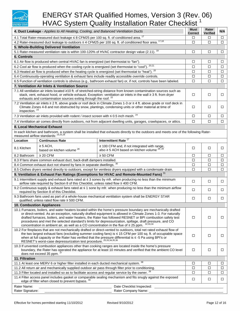
ENERGY STAR Qualified Homes, Version 3 (Rev. 06) HVAC System Quality Installation Rater Checklist 1
4. Duct Leakage - Applies to All Heating, Cooling, and Balanced Ventilation Ducts Must Correct
Rater Verified N/A
4.1 Total Rater-measured duct leakage ≤ 8 CFM25 per 100 sq. ft. of conditioned area. 17
4.2 Rater-measured duct leakage to outdoors ≤ 4 CFM25 per 100 sq. ft. of conditioned floor area. 17,18
5. Whole-Building Delivered Ventilation 5.1 Rater-measured ventilation rate is within 100-120% of HVAC contractor design value (2.11). 19
6. Controls 6.1 Air flow is produced when central HVAC fan is energized (set thermostat to “fan”).
6.2 Cool air flow is produced when the cooling cycle is energized (set thermostat to “cool”). 20,21
6.3 Heated air flow is produced when the heating cycle is energized (set thermostat to “heat”). 20
6.4 Continuously-operating ventilation & exhaust fans include readily accessible override controls.
6.5 Function of ventilation controls is obvious (e.g., bathroom exhaust fan) or, if not, controls have been labeled.
7. Ventilation Air Inlets & Ventilation Source 7.1 All ventilation air inlets located ≥10 ft. of stretched-string distance from known contamination sources such as
stack, vent, exhaust hood, or vehicle exhaust. Exception: ventilation air inlets in the wall ≥ 3 ft. from dryer exhausts and contamination sources exiting through the roof. 22
7.2 Ventilation air inlets ≥ 2 ft. above grade or roof deck in Climate Zones 1-3 or ≥ 4 ft. above grade or roof deck in Climate Zones 4-8 and not obstructed by snow, plantings, condensing units or other material at time of inspection. 23
7.3 Ventilation air inlets provided with rodent / insect screen with ≤ 0.5 inch mesh. 24
7.4 Ventilation air comes directly from outdoors, not from adjacent dwelling units, garages, crawlspaces, or attics.
8. Local Mechanical Exhaust In each kitchen and bathroom, a system shall be installed that exhausts directly to the outdoors and meets one of the following Rater-measured airflow standards: 19,25,26
Location Continuous Rate Intermittent Rate 27
8.1 Kitchen ≥ 5 ACH, based on kitchen volume 28
≥ 100 CFM and, if not integrated with range, also ≥ 5 ACH based on kitchen volume 28, 29
8.2 Bathroom ≥ 20 CFM ≥ 50 CFM
8.3 If fans share common exhaust duct, back-draft dampers installed.
8.4 Common exhaust duct not shared by fans in separate dwellings. 30
8.5 Clothes dryers vented directly to outdoors, except for ventless dryers equipped with a condensate drain.
9. Ventilation & Exhaust Fan Ratings (Exemptions for HVAC and Remote-Mounted Fans) 31
9.1 Intermittent supply and exhaust fans rated at ≤ 3 sones by mfr. when producing no less than the minimum airflow rate required by Section 8 of this Checklist, unless rated flow ≥ 400 CFM.
9.2 Continuous supply & exhaust fans rated at ≤ 1 sone by mfr. when producing no less than the minimum airflow required by Section 8 of this Checklist.
9.3 Bathroom fans used as part of a whole-house mechanical ventilation system shall be ENERGY STAR qualified; unless rated flow rate ≥ 500 CFM.
10. Combustion Appliances 10.1 Furnaces, boilers, and water heaters located within the home’s pressure boundary are mechanically drafted
or direct-vented. As an exception, naturally drafted equipment is allowed in Climate Zones 1-3. For naturally drafted furnaces, boilers, and water heaters, the Rater has followed RESNET or BPI combustion safety test procedures and met the selected standard’s limits for depressurization, spillage, draft pressure, and CO concentration in ambient air, as well as a CO concentration in the flue of ≤ 25 ppm. 32,33,34
10.2 For fireplaces that are not mechanically drafted or direct-vented to outdoors, total net rated exhaust flow of the two largest exhaust fans (excluding summer cooling fans) is ≤ 15 CFM per 100 sq. ft. of occupiable space when at full capacity or the Rater has verified that the pressure differential is ≤ -5 Pa using BPI’s or RESNET’s worst-case depressurization test procedure. 25,33,34,35,36
10.3 If unvented combustion appliances other than cooking ranges are located inside the home’s pressure boundary, the Rater has operated the appliance for at least 10 minutes and verified that the ambient CO level does not exceed 35 ppm. 37
11. Filtration 11.1 At least one MERV 6 or higher filter installed in each ducted mechanical system. 38
11.2 All return air and mechanically supplied outdoor air pass through filter prior to conditioning.
11.3 Filter located and installed so as to facilitate access and regular service by the owner. 39
11.4 Filter access panel includes gasket or comparable sealing mechanism and fits snugly against the exposed edge of filter when closed to prevent bypass. 40
Rater Name: _______________________________________ Date Checklist Inspected: _____________________________________ Rater Signature: ____________________________________ Rater Company Name: ________________________________________
Effective for homes permitted starting 11/10/2012 Revised 9/10/2012 Page 12 of 16
ENERGY STAR Qualified Homes, Version 3 (Rev. 06) HVAC System Quality Installation Rater Checklist 1
Notes: 1. This Checklist is designed to align with the requirements of ASHRAE 62.2-2010 and published addenda and ANSI / ACCA’s 5 QI-2007
protocol, thereby improving the performance of HVAC equipment in new homes when compared to homes built to minimum code. However, these features alone cannot prevent all ventilation, indoor air quality, and HVAC problems, (e.g., those caused by a lack of maintenance by occupants). Therefore, this Checklist is not a guarantee of proper ventilation, indoor air quality, or HVAC performance. This Checklist with supporting documents may also be used to demonstrate compliance with Indoor airPLUS specifications 4.1, 4.2, 4.5, 4.6, and 7.1.
2. The Rater is only responsible for ensuring that the Contractor has completed the Contractor Checklist in its entirety and verifying the discrete objective parameters referenced in Section 1 of this Checklist, not for assessing the accuracy of the load calculations or field verifications included or for verifying the accuracy of every input on the Contractor Checklist.
3. For homes with a date of final inspection through 12/31/2012: Item 1.2.1 is permitted to be within +/- 5 degrees of the 1% and 99% ACCA Manual J design temperatures for the contractor-designated design location. In addition, for each house plan with multiple configurations (e.g., orientations, elevations, options), the Rater shall confirm that the parameters listed in Items 1.2.2 to 1.2.6 are aligned with either: the rated home or with the plans for the configuration used to calculate the loads, as provided by the contractor. For homes with a date of final inspection on or after 01/01/2013: Item 1.2.1 shall match the 1% and 99% ACCA Manual J design temperatures for the contractor-designated design location. In addition, for each house plan with multiple configurations (e.g., orientations, elevations, options), the Rater shall confirm that the parameters listed in Items 1.2.2 to 1.2.6 are aligned with the rated home.
4. The Rater shall either confirm that the contractor selected the geographically closest available location or collect from the contractor a justification for the selected location. The Rater need not evaluate the legitimacy of the justification to qualify the home.
5. The number of occupants among all HVAC systems in the home shall be equal to the number of RESNET-defined bedrooms plus one. Occupants listed for systems for which the header of the Contractor Checklist indicates that it is designed to handle temporary occupant loads, as defined in Footnote 3 of the Contractor Checklist, shall be permitted to exceed this limit.
6. “Predominant” is defined as the SHGC value used in the greatest amount of window area in the home. 7. For cooling systems, the next largest nominal piece of equipment may be used that is available to satisfy the latent and sensible
requirements. Single-speed systems generally have OEM nominal size increments of ½ ton. Multi-speed or multi-stage equipment may have OEM nominal size increments of one ton. Therefore, the use of these advanced system types can provide extra flexibility to meet the equipment sizing requirements.
8. In cases where the condenser unit is installed after the time of inspection by the Rater, the HVAC manufacturer and model numbers on installed equipment can be documented through the use of photographs provided by the HVAC Contractor after installation is complete.
9. If contractor has indicated that an OEM test procedure has been used in place of a sub-cooling or super-heat process and documentation has been attached that defines this procedure, then the box for “N/A” shall be checked for this Item.
10. If any Item in Sections 6 through 12 of the HVAC System QI Contractor Checklist is applicable to the home and, therefore, completed by an HVAC contractor, then the Rater must confirm that the contractor holds the necessary credentials. HVAC contractors must be credentialed by an EPA-recognized HVAC Quality Installation Training and Oversight Organization (H-QUITO). An explanation of this credentialing process and links to H-QUITOs, which maintain lists of credentialed contractors, can be found at www.energystar.gov/newhomesHVAC.
11. Items 2.7 and 2.8 do not apply to ventilation ducts. 12. Kinks are to be avoided and are caused when ducts are bent across sharp corners such as framing members. Sharp bends are to be
avoided and occur when the radius of the turn in the duct is less than one duct diameter. 13. Ducts shall not include coiled or looped ductwork except to the extent needed for acoustical control. Balancing dampers or proper duct
sizing shall be used instead of loops to limit flow to diffusers. When balancing dampers are used, they shall be located at the trunk to limit noise unless the trunk will not be accessible when the balancing process is conducted. In such cases, Opposable Blade Dampers (OBD) or dampers that are located in the duct boot are permitted.
14. For homes with a date of final inspection through 12/31/2012: Homes are permitted to be qualified without enforcement of this item to provide architects and designers with additional time to integrate these features into their homes. For homes with a date of final inspection on or after 01/01/2013: Homes shall meet this item to be qualified.
15. For HVAC system with multi-speed fans, the highest design fan speed shall be used when verifying this requirement. 16. EPA recommends, but does not require, that all metal ductwork not encompassed by Section 3 (e.g., exhaust ducts, duct boots, ducts in
conditioned space) also be insulated and that insulation be sealed to duct boots to prevent condensation. 17. Duct leakage shall be determined and documented by a Rater using a RESNET-approved testing protocol only after all components of the
system have been installed including the air handler, the ductwork, the duct boots, and the register grilles atop the finished surface (e.g., drywall, carpeting, flooring). Leakage limits shall be assessed on a per-system, rather than per-home, basis. For balanced ventilation ducts that are not connected to space heating or cooling systems, a Rater is permitted to visually verify, in lieu of duct leakage testing, that all seams and connections are sealed with mastic or metal tape and all duct boots are sealed to floor, wall, or ceiling using caulk, foam, or mastic tape.
18. For homes that have ≤ 1,200 sq. ft. of conditioned floor area, measured duct leakage to outdoors shall be ≤ 5 CFM25 per 100 sq. ft. of conditioned floor area. Testing of duct leakage to the outside can be waived if all ducts & air handling equipment are located within the home’s air and thermal barriers AND envelope leakage has been tested to be less than or equal to half of the Prescriptive Path infiltration limit for the Climate Zone where the home is to be built. Alternatively, testing of duct leakage to the outside can be waived if total duct leakage is ≤ 4 CFM25 per 100 sq. ft. of conditioned floor area, or ≤ 5 CFM25 per 100 sq. ft. of conditioned floor area for homes that have less than 1,200 sq. ft. of conditioned floor area.
19. The whole-house ventilation air flow and local exhaust air flows shall be measured by the Rater using a flow hood, flow grid, anemometer (in accordance with AABC, NEBB or ASHRAE procedures), or substantially equivalent method.
Effective for homes permitted starting 11/10/2012 Revised 9/10/2012 Page 13 of 16
ENERGY STAR Qualified Homes, Version 3 (Rev. 06) HVAC System Quality Installation Rater Checklist 1
20. In cases where the condenser unit is installed after the time of inspection by the Rater, the Rater is exempt from verifying Item 6.2 when the condenser is for an AC unit and also Item 6.3 when the condenser is for a heatpump unit.
21. To prevent potential equipment damage, the Rater shall not conduct this test if the outdoor temperature is ≤ 55°F or, if known, below the manufacturer-recommended minimum operating temperature for the cooling cycle. When this occurs, the Rater shall mark ‘N/A’ on the Checklist for this item.
22. The outlet and inlet of balanced ventilation systems shall meet these spacing requirements unless manufacturer instructions indicate that a smaller distance may be used. However, if this occurs the manufacturer’s instructions shall be collected for documentation purposes.
23. EPA will permit the use of reduced ventilation air inlet heights in North Carolina. The minimum required height in North Carolina for Climate Zone 4 will be reduced from 4 feet to 2 feet and in Climate Zone 5 from 4 feet to 2.5 feet based on historical snowfall data for this state. Note that EPA is evaluating the potential to reduce inlet heights in other regions based upon historical snowfall data.
24. Without proper maintenance, ventilation air inlet screens often become filled with debris. Therefore, EPA recommends, but does not require, that these ventilation air inlets be located so as to facilitate access and regular service by the owner.
25. Per ASHRAE 62.2-2010, an exhaust system is one or more fans that remove air from the building, causing outdoor air to enter by ventilation inlets or normal leakage paths through the building envelope (e.g., bath exhaust fans, range hoods, clothes dryers).
26. Per ASHRAE 62.2-2010, a bathroom is any room containing a bathtub, shower, spa, or similar source of moisture. 27. An intermittent mechanical exhaust system, where provided, shall be designed to operate as needed by the occupant. Control devices
shall not impede occupant control in intermittent systems. 28. Kitchen volume shall be determined by drawing the smallest possible rectangle on the floor plan that encompasses all cabinets, pantries,
islands, and peninsulas and multiplying by the average ceiling height for this area. Cabinet volume shall be included in the kitchen volume calculation.
29. All intermittent kitchen exhaust fans must be capable of exhausting at least 100 CFM. In addition, if the fan is not part of a vented range hood or appliance-range hood combination (i.e., if the fan is not integrated with the range), then it must also be capable of exhausting ≥ 5 ACH, based on the kitchen volume. Also, for intermittent kitchen exhaust fans that are integrated with microwaves, a rated air flow rate ≥ 200 CFM may be used in lieu of measuring the actual air flow rate.
30. Exhaust outlets from more than one dwelling unit may be served by a single exhaust fan if the fan runs continuously or if each outlet has a back-draft damper to prevent cross-contamination when the fan is not running.
31. Fans exempted from this requirement include HVAC air handlers and remote-mounted fans. To be considered for this exemption, a remote-mounted fan must be mounted outside the habitable spaces, bathrooms, toilets, and hallways and there shall be ≥ 4 ft. ductwork between the fan and intake grill. Per ASHRAE 62.2-2010, habitable spaces are intended for continual human occupancy; such space generally includes areas used for living, sleeping, dining, and cooking but does not generally include bathrooms, toilets, hallways, storage areas, closets, or utility rooms.
32. Per the 2009 International Mechanical Code, a direct-vent appliance is one that is constructed and installed so that all air for combustion is derived from the outdoor atmosphere and all flue gases are discharged to the outside atmosphere; a mechanical draft system is a venting system designed to remove flue or vent gases by mechanical means consisting of an induced draft portion under non-positive static pressure or a forced draft portion under positive static pressure; and a natural draft system is a venting system designed to remove flue or vent gases under nonpositive static vent pressure entirely by natural draft.
33. The pressure boundary is the primary enclosure boundary separating indoor and outdoor air. For example, a volume that has more leakage to outside than to conditioned space would be outside the pressure boundary.
34. Raters shall use either the Building Performance Institute’s (BPI’s) Combustion Safety Test Procedure for Vented Appliances or RESNET’s Interim Guidelines for Combustion Appliance Testing & Writing Work Scope and be BPI-certified or RESNET-certified to follow the protocol. If using RESNET’s worst-case depressurization protocol to evaluate fireplaces, per Item 10.2, the blower door shall not be set to exhaust 300 CFM to simulate the fireplace in operation, but the remainder of the protocol shall be followed.
35. Per ASHRAE 62.2-2010 and pub. addenda, the term “net-exhaust flow” is defined as flow through an exhaust system minus the compensating outdoor airflow through any supply system that is interlocked to the exhaust system. “Net supply flow” is intended to represent the inverse. If net exhaust flow exceeds allowable limit, it shall be reduced or compensating outdoor airflow provided.
36. Per ASHRAE 62.2-2010, occupiable space is any enclosed space inside the pressure boundary and intended for human activities, including, but not limited to, all habitable spaces, toilets, closets, halls, storage and utility areas, and laundry areas. See Footnote 31 for definition of “habitable spaces”.
37. The minimum volume of combustion air required for safe operation by the manufacturer and / or code shall be met or exceeded. Also, in accordance with the National Fuel Gas Code, ANSI Z223.l / NFPA54, unvented room heaters shall not be installed in bathrooms or bedrooms.
38. Per ASHRAE 62.2-2010, ducted mechanical systems are those that supply air to an occupiable space through ductwork exceeding 10 ft. in length and through a thermal conditioning component, except for evaporative coolers. Systems that do not meet this definition are exempt from this requirement. Also, mini-split systems typically do not have MERV-rated filters available for use and are, therefore, also exempted under this version of the guidelines.
39. HVAC filters located in the attic shall be considered accessible to the owner if drop-down stairs provide access to attic and a permanently installed walkway has been provided between the attic access location and the filter.
40. The filter media box (i.e., the component in the HVAC system that houses the filter) may be either site-fabricated by the installer or prefabricated by the manufacturer to meet this requirement. These requirements only apply when the filter is installed in a filter media box located in the HVAC system, not when the filter is installed flush with the return grill.
Effective for homes permitted starting 11/10/2012 Revised 9/10/2012 Page 14 of 16
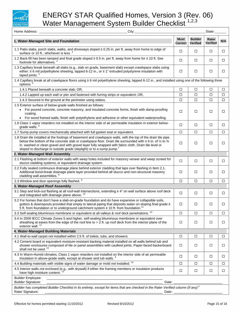
ENERGY STAR Qualified Homes, Version 3 (Rev. 06) Water Management System Builder Checklist 1,2,3
Home Address: _______________________________________________ City: ______________________________________ State:______
1. Water-Managed Site and Foundation Must Correct
Builder Verified
Rater Verified N/A
1.1 Patio slabs, porch slabs, walks, and driveways sloped ≥ 0.25 in. per ft. away from home to edge of surface or 10 ft., whichever is less. 4
1.2 Back-fill has been tamped and final grade sloped ≥ 0.5 in. per ft. away from home for ≥ 10 ft. See footnote for alternatives. 4
1.3 Capillary break beneath all slabs (e.g., slab on grade, basement slab) except crawlspace slabs using either: ≥ 6 mil polyethylene sheeting, lapped 6-12 in., or ≥ 1” extruded polystyrene insulation with taped joints. 5
1.4 Capillary break at all crawlspace floors using ≥ 6 mil polyethylene sheeting, lapped 6-12 in., and installed using one of the following three options: 5
1.4.1 Placed beneath a concrete slab; OR,
1.4.2 Lapped up each wall or pier and fastened with furring strips or equivalent; OR,
1.4.3 Secured in the ground at the perimeter using stakes.
1.5 Exterior surface of below-grade walls finished as follows: For poured concrete, concrete masonry, and insulated concrete forms, finish with damp-proofing
coating. For wood framed walls, finish with polyethylene and adhesive or other equivalent waterproofing.
1.6 Class 1 vapor retarders not installed on the interior side of air permeable insulation in exterior below-grade walls. 6
1.7 Sump pump covers mechanically attached with full gasket seal or equivalent.
1.8 Drain tile installed at the footings of basement and crawlspace walls, with the top of the drain tile pipe below the bottom of the concrete slab or crawlspace floor. Drain tile surrounded with ≥ 6 in. of ½ to ¾ in. washed or clean gravel and with gravel layer fully wrapped with fabric cloth. Drain tile level or sloped to discharge to outside grade (daylight) or to a sump pump.7
2. Water-Managed Wall Assembly 2.1 Flashing at bottom of exterior walls with weep holes included for masonry veneer and weep screed for
stucco cladding systems, or equivalent drainage system.
2.2 Fully sealed continuous drainage plane behind exterior cladding that laps over flashing in Item 2.1. Additional bond-break drainage plane layer provided behind all stucco and non-structural masonry cladding wall assemblies. 8
2.3 Window and door openings fully flashed. 9
3. Water-Managed Roof Assembly 3.1 Step and kick-out flashing at all roof-wall intersections, extending ≥ 4” on wall surface above roof deck
and integrated with drainage plane above. 10
3.2 For homes that don’t have a slab-on-grade foundation and do have expansive or collapsible soils, gutters & downspouts provided that empty to lateral piping that deposits water on sloping final grade ≥ 5 ft. from foundation or to underground catchment system ≥ 10 ft. from foundation.11
3.3 Self-sealing bituminous membrane or equivalent at all valleys & roof deck penetrations. 12
3.4 In 2009 IECC Climate Zones 5 and higher, self-sealing bituminous membrane or equivalent over sheathing at eaves from the edge of the roof line to > 2 ft. up roof deck from the interior plane of the exterior wall. 12
4. Water-Managed Building Materials 4.1 Wall-to-wall carpet not installed within 2.5 ft. of toilets, tubs, and showers.
4.2 Cement board or equivalent moisture-resistant backing material installed on all walls behind tub and shower enclosures composed of tile or panel assemblies with caulked joints. Paper-faced backerboard shall not be used. 13
4.3 In Warm-Humid climates, Class 1 vapor retarders not installed on the interior side of air permeable insulation in above-grade walls, except at shower and tub walls. 6
4.4 Building materials with visible signs of water damage or mold not installed. 14
4.5 Interior walls not enclosed (e.g., with drywall) if either the framing members or insulation products have high moisture content. 15
Builder Employee: ______________________________________________________________ Builder Signature: ______________________________________________________________ Date: __________________________ Builder has completed Builder Checklist in its entirety, except for items that are checked in the Rater Verified column (if any) 2
Rater Signature: _______________________________________________________________ Date: __________________________
Effective for homes permitted starting 11/10/2012 Revised 9/10/2012 Page 15 of 16
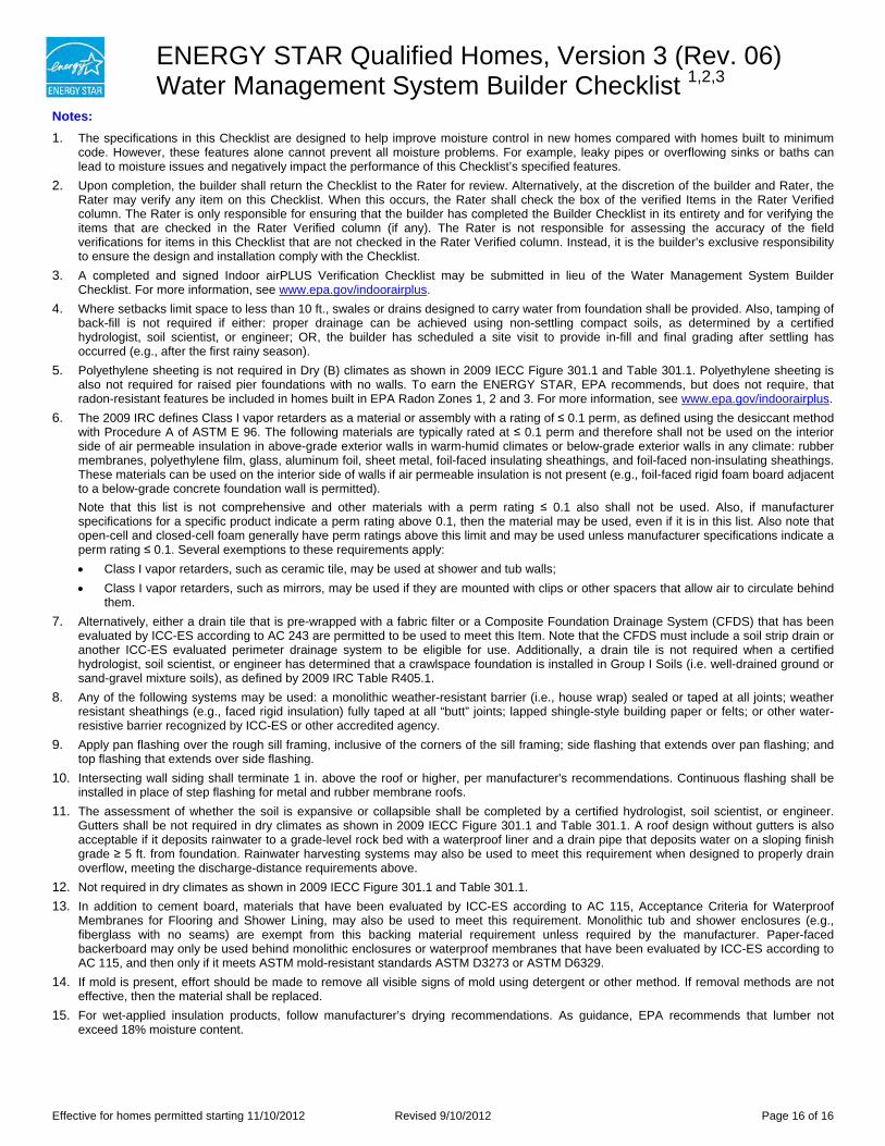
ENERGY STAR Qualified Homes, Version 3 (Rev. 06) Water Management System Builder Checklist 1,2,3
Notes: 1. The specifications in this Checklist are designed to help improve moisture control in new homes compared with homes built to minimum
code. However, these features alone cannot prevent all moisture problems. For example, leaky pipes or overflowing sinks or baths can lead to moisture issues and negatively impact the performance of this Checklist’s specified features.
2. Upon completion, the builder shall return the Checklist to the Rater for review. Alternatively, at the discretion of the builder and Rater, the Rater may verify any item on this Checklist. When this occurs, the Rater shall check the box of the verified Items in the Rater Verified column. The Rater is only responsible for ensuring that the builder has completed the Builder Checklist in its entirety and for verifying the items that are checked in the Rater Verified column (if any). The Rater is not responsible for assessing the accuracy of the field verifications for items in this Checklist that are not checked in the Rater Verified column. Instead, it is the builder’s exclusive responsibility to ensure the design and installation comply with the Checklist.
3. A completed and signed Indoor airPLUS Verification Checklist may be submitted in lieu of the Water Management System Builder Checklist. For more information, see www.epa.gov/indoorairplus.
4. Where setbacks limit space to less than 10 ft., swales or drains designed to carry water from foundation shall be provided. Also, tamping of back-fill is not required if either: proper drainage can be achieved using non-settling compact soils, as determined by a certified hydrologist, soil scientist, or engineer; OR, the builder has scheduled a site visit to provide in-fill and final grading after settling has occurred (e.g., after the first rainy season).
5. Polyethylene sheeting is not required in Dry (B) climates as shown in 2009 IECC Figure 301.1 and Table 301.1. Polyethylene sheeting is also not required for raised pier foundations with no walls. To earn the ENERGY STAR, EPA recommends, but does not require, that radon-resistant features be included in homes built in EPA Radon Zones 1, 2 and 3. For more information, see www.epa.gov/indoorairplus.
6. The 2009 IRC defines Class I vapor retarders as a material or assembly with a rating of ≤ 0.1 perm, as defined using the desiccant method with Procedure A of ASTM E 96. The following materials are typically rated at ≤ 0.1 perm and therefore shall not be used on the interior side of air permeable insulation in above-grade exterior walls in warm-humid climates or below-grade exterior walls in any climate: rubber membranes, polyethylene film, glass, aluminum foil, sheet metal, foil-faced insulating sheathings, and foil-faced non-insulating sheathings. These materials can be used on the interior side of walls if air permeable insulation is not present (e.g., foil-faced rigid foam board adjacent to a below-grade concrete foundation wall is permitted). Note that this list is not comprehensive and other materials with a perm rating ≤ 0.1 also shall not be used. Also, if manufacturer specifications for a specific product indicate a perm rating above 0.1, then the material may be used, even if it is in this list. Also note that open-cell and closed-cell foam generally have perm ratings above this limit and may be used unless manufacturer specifications indicate a perm rating ≤ 0.1. Several exemptions to these requirements apply: Class I vapor retarders, such as ceramic tile, may be used at shower and tub walls; Class I vapor retarders, such as mirrors, may be used if they are mounted with clips or other spacers that allow air to circulate behind
them. 7. Alternatively, either a drain tile that is pre-wrapped with a fabric filter or a Composite Foundation Drainage System (CFDS) that has been
evaluated by ICC-ES according to AC 243 are permitted to be used to meet this Item. Note that the CFDS must include a soil strip drain or another ICC-ES evaluated perimeter drainage system to be eligible for use. Additionally, a drain tile is not required when a certified hydrologist, soil scientist, or engineer has determined that a crawlspace foundation is installed in Group I Soils (i.e. well-drained ground or sand-gravel mixture soils), as defined by 2009 IRC Table R405.1.
8. Any of the following systems may be used: a monolithic weather-resistant barrier (i.e., house wrap) sealed or taped at all joints; weather resistant sheathings (e.g., faced rigid insulation) fully taped at all “butt” joints; lapped shingle-style building paper or felts; or other water-resistive barrier recognized by ICC-ES or other accredited agency.
9. Apply pan flashing over the rough sill framing, inclusive of the corners of the sill framing; side flashing that extends over pan flashing; and top flashing that extends over side flashing.
10. Intersecting wall siding shall terminate 1 in. above the roof or higher, per manufacturer's recommendations. Continuous flashing shall be installed in place of step flashing for metal and rubber membrane roofs.
11. The assessment of whether the soil is expansive or collapsible shall be completed by a certified hydrologist, soil scientist, or engineer. Gutters shall be not required in dry climates as shown in 2009 IECC Figure 301.1 and Table 301.1. A roof design without gutters is also acceptable if it deposits rainwater to a grade-level rock bed with a waterproof liner and a drain pipe that deposits water on a sloping finish grade ≥ 5 ft. from foundation. Rainwater harvesting systems may also be used to meet this requirement when designed to properly drain overflow, meeting the discharge-distance requirements above.
12. Not required in dry climates as shown in 2009 IECC Figure 301.1 and Table 301.1. 13. In addition to cement board, materials that have been evaluated by ICC-ES according to AC 115, Acceptance Criteria for Waterproof
Membranes for Flooring and Shower Lining, may also be used to meet this requirement. Monolithic tub and shower enclosures (e.g., fiberglass with no seams) are exempt from this backing material requirement unless required by the manufacturer. Paper-faced backerboard may only be used behind monolithic enclosures or waterproof membranes that have been evaluated by ICC-ES according to AC 115, and then only if it meets ASTM mold-resistant standards ASTM D3273 or ASTM D6329.
14. If mold is present, effort should be made to remove all visible signs of mold using detergent or other method. If removal methods are not effective, then the material shall be replaced.
15. For wet-applied insulation products, follow manufacturer’s drying recommendations. As guidance, EPA recommends that lumber not exceed 18% moisture content.
Effective for homes permitted starting 11/10/2012 Revised 9/10/2012 Page 16 of 16
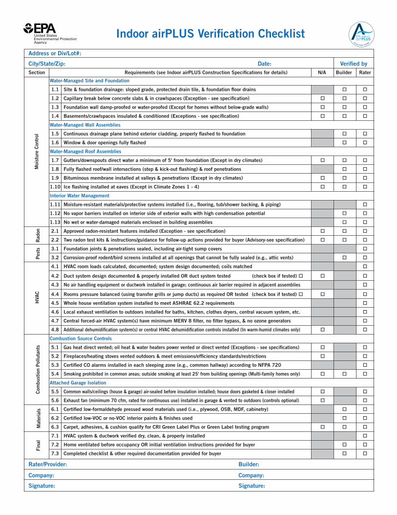
Indoor airPLUS Verification Checklist
Address or Div/Lot#:
City/State/Zip: Date: Verified by Section Requirements (see Indoor airPLUS Construction Specifications for details) N/A Builder Rater
Water-Managed Site and Foundation
1.1 Site & foundation drainage: sloped grade, protected drain tile, & foundation floor drains o o
1.2 Capillary break below concrete slabs & in crawlspaces (Exception - see specification) o o o
1.3 Foundation wall damp-proofed or water-proofed (Except for homes without below-grade walls) o o o
1.4 Basements/crawlspaces insulated & conditioned (Exceptions - see specification) o o o
Water-Managed Wall Assemblies
1.5 Continuous drainage plane behind exterior cladding, properly flashed to foundation o o
1.6 Window & door openings fully flashed o o
Water-Managed Roof Assemblies
1.7 Gutters/downspouts direct water a minimum of 5' from foundation (Except in dry climates) o o o
1.8 Fully flashed roof/wall intersections (step & kick-out flashing) & roof penetrations o o
1.9 Bituminous membrane installed at valleys & penetrations (Except in dry climates) o o o
1.10 Ice flashing installed at eaves (Except in Climate Zones 1 - 4) o o o
Interior Water Management
1.11 Moisture-resistant materials/protective systems installed (i.e., flooring, tub/shower backing, & piping) o
1.12 No vapor barriers installed on interior side of exterior walls with high condensation potential o o
1.13 No wet or water-damaged materials enclosed in building assemblies o o
2.1 Approved radon-resistant features installed (Exception - see specification) o o o
2.2 Two radon test kits & instructions/guidance for follow-up actions provided for buyer (Advisory-see specification) o o o
3.1 Foundation joints & penetrations sealed, including air-tight sump covers o
3.2 Corrosion-proof rodent/bird screens installed at all openings that cannot be fully sealed (e.g., attic vents) o o
4.1 HVAC room loads calculated, documented; system design documented; coils matched o
4.2 Duct system design documented & properly installed OR duct system tested (check box if tested) o o o
4.3 No air handling equipment or ductwork installed in garage; continuous air barrier required in adjacent assemblies o
4.4 Rooms pressure balanced (using transfer grills or jump ducts) as required OR tested (check box if tested) o o o
4.5 Whole house ventilation system installed to meet ASHRAE 62.2 requirements o
4.6 Local exhaust ventilation to outdoors installed for baths, kitchen, clothes dryers, central vacuum system, etc. o
4.7 Central forced-air HVAC system(s) have minimum MERV 8 filter, no filter bypass, & no ozone generators o
4.8 Additional dehumidification system(s) or central HVAC dehumidification controls installed (In warm-humid climates only) o o
Combustion Source Controls
5.1 Gas heat direct vented; oil heat & water heaters power vented or direct vented (Exceptions - see specifications) o o
5.2 Fireplaces/heating stoves vented outdoors & meet emissions/efficiency standards/restrictions o o
5.3 Certified CO alarms installed in each sleeping zone (e.g., common hallway) according to NFPA 720 o
5.4 Smoking prohibited in common areas; outside smoking at least 25' from building openings (Multi-family homes only) o o o
Attached Garage Isolation
5.5 Common walls/ceilings (house & garage) air-sealed before insulation installed; house doors gasketed & closer installed o o
5.6 Exhaust fan (minimum 70 cfm, rated for continuous use) installed in garage & vented to outdoors (controls optional) o o
6.1 Certified low-formaldehyde pressed wood materials used (i.e., plywood, OSB, MDF, cabinetry) o o
6.2 Certified low-VOC or no-VOC interior paints & finishes used o o
6.3 Carpet, adhesives, & cushion qualify for CRI Green Label Plus or Green Label testing program o o o
7.1 HVAC system & ductwork verified dry, clean, & properly installed o
7.2 Home ventilated before occupancy OR initial ventilation instructions provided for buyer o o
7.3 Completed checklist & other required documentation provided for buyer o o
Rater/Provider: Builder: Company: Company: Signature: Signature:
Moi
stur
e Co
ntro
lCo
mbu
stio
n Po
lluta
nts
Pest
sH
VAC
Fina
lR
adon
Mat
eria
ls
Guidance for Completing the Indoor airPLUS Verification Checklist:1. Only ENERGY STAR qualified homes verified to comply with these specifications can earn the Indoor airPLUS label. See Indoor
airPLUS Construction Specifications for full descriptions of the requirements, terms, exceptions, abbreviations, references, and climate map used in this checklist. Verification is not complete until this checklist is completed in full and signed.
2. Check one box per line. Check “N/A” for specifications that do not apply for specific conditions (e.g., climate) according to the Exceptions described in the Indoor airPLUS Construction Specifications. Check either “Builder” or “Rater” for all other items to indicate who verified each item. Items may be verified visually on site during construction, by reviewing photographs taken during construction, by checking documentation, or through equivalent methods as appropriate. If using a performance testing alternative to meet requirement 4.2 or 4.4, the box marked “Tested” must be checked and testing documentation must be pro-vided in the Home Energy Rating System/Builder Option Package (HERS/BOP) file.
3. The rater who conducted the verification, or a responsible party from the rater’s company, must sign the completed verification checklist. The builder must sign the checklist if any items in the “Builder” column are checked, and by so doing accepts full responsibility for verifying that those items meet Indoor airPLUS requirements.
4. The builder provides one copy of the completed and signed checklist for the buyer. The HERS/BOP provider or rater files a copy with HERS/BOP and ENERGY STAR documentation (e.g., Thermal Bypass Checklist) for the home.
5. The checklist may be completed for a batch of homes using a RESNET-approved sampling protocol when qualifying homes as ENERGY STAR. For example, if the approved sampling protocol requires rating one in seven homes, then the checklist will be completed for the one home that was rated.
Note: The Indoor airPLUS Construction Specifications are designed to help improve indoor air quality (IAQ) in new homes compared with homes built to minimum code. These measures alone cannot prevent all IAQ problems; occupant behavior is also important. For example, smoking indoors would negatively impact a home’s IAQ and the performance of the specified Indoor airPLUS measures.
Notes:
For further information on the Indoor airPLUS program, visit epa.gov/indoorairplus.
All Indoor airPLUS qualified homes meet strict
guidelines for energy efficiency set by ENERGY STAR,
the nationally-recognized symbol for energy efficiency.
Qualified homes earn the
Indoor airPLUS label.
Place it next to the
ENERGY STAR label.
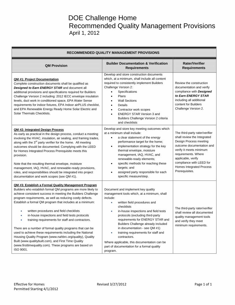
DOE Challenge Home Recommended Quality Management Provisions
April 1, 2012
Effective for Homes Revised 3/27/2012 Page 1 of 1 Permitted Starting 4/1/2012
RECOMMENDED QUALITY MANAGEMENT PROVISIONS
QM Provision
Builder Documentation & Verification
Requirements
Rater/Verifier
Requirements
QM #1: Project Documentation
Complete construction documents shall be qualified as
Designed to Earn ENERGY STAR and document all
additional provisions and specifications required for Builders
Challenge Version 2 including: 2012 IECC envelope insulation
levels, duct work in conditioned space, EPA Water Sense
requirements for indoor fixtures, EPA Indoor airPLUS checklist,
and EPA Renewable Energy Ready Home Solar Electric and
Solar Thermals Checklists.
Develop and store construction documents
which, at a minimum, shall include all content
required to consistently implement Builders
Challenge Version 2:
Specifications
Plans
Wall Sections
Details
Contractor work scopes
ENERGY STAR Version 3 and
Builders Challenge Version 2 criteria
and checklists
Review the construction
documentation and verify
compliance with Designed
to Earn ENERGY STAR
including all additional
content for Builders
Challenge Version 2.
QM #2: Integrated Design Process
As early as practical in the design process, conduct a meeting
involving the HVAC, insulation, air sealing, and framing trades,
along with the 3rd party verifier for the home. All meeting
outcomes should be documented. Complying with the LEED
for Homes Integrated Process Prerequisite meets this
provision.
Note that the resulting thermal envelope, moisture
management, IAQ, HVAC, and renewable-ready provisions,
roles, and responsibilities should be integrated into project
documentation and work scopes (see QM #1).
Develop and store key meeting outcomes which
at a minimum shall include:
a clear statement of the energy
performance target for the home;
implementation strategy for the key
thermal envelope, moisture
management, IAQ, HVAC, and
renewable-ready elements;
specific methods for reaching these
targets; and
assigned party responsible for each
specific measure/step.
The third-party rater/verifier
shall review the Integrated
Design Process meeting
outcome documentation and
verify it meets minimum
requirements. Where
applicable, verify
compliance with LEED for
Homes Integrated Process
Prerequisites.
QM #3: Establish a Formal Quality Management Program
Builders who establish formal QM programs are more likely to
achieve consistent success in meeting the Builders Challenge
program requirements, as well as reducing costly defects.
Establish a formal QM program that includes at a minimum:
written procedures and field checklists
in-house inspections and field tests protocols
training requirements for staff and contractors.
There are a number of formal quality programs that can be
used to achieve these requirements including the National
Housing Quality Program (www.nahbrc.org/quality), Quality
Built (www.qualitybuilt.com), and First Time Quality
(www.firsttimequality.com). These programs are based on
ISO 9001.
Document and implement key quality
management tools which, at a minimum, shall
include:
written field procedures and
checklists
in-house inspections and field tests
protocols (excluding third-party
requirements for ENERGY STAR and
Builders Challenge already included
in documentation - see QM #1)
training requirements for staff and
contractors.
Where applicable, this documentation can be
part of documentation for a formal quality
program.
The third-party rater/verifier
shall review all documented
quality management tools
and verify they meet
minimum requirements.
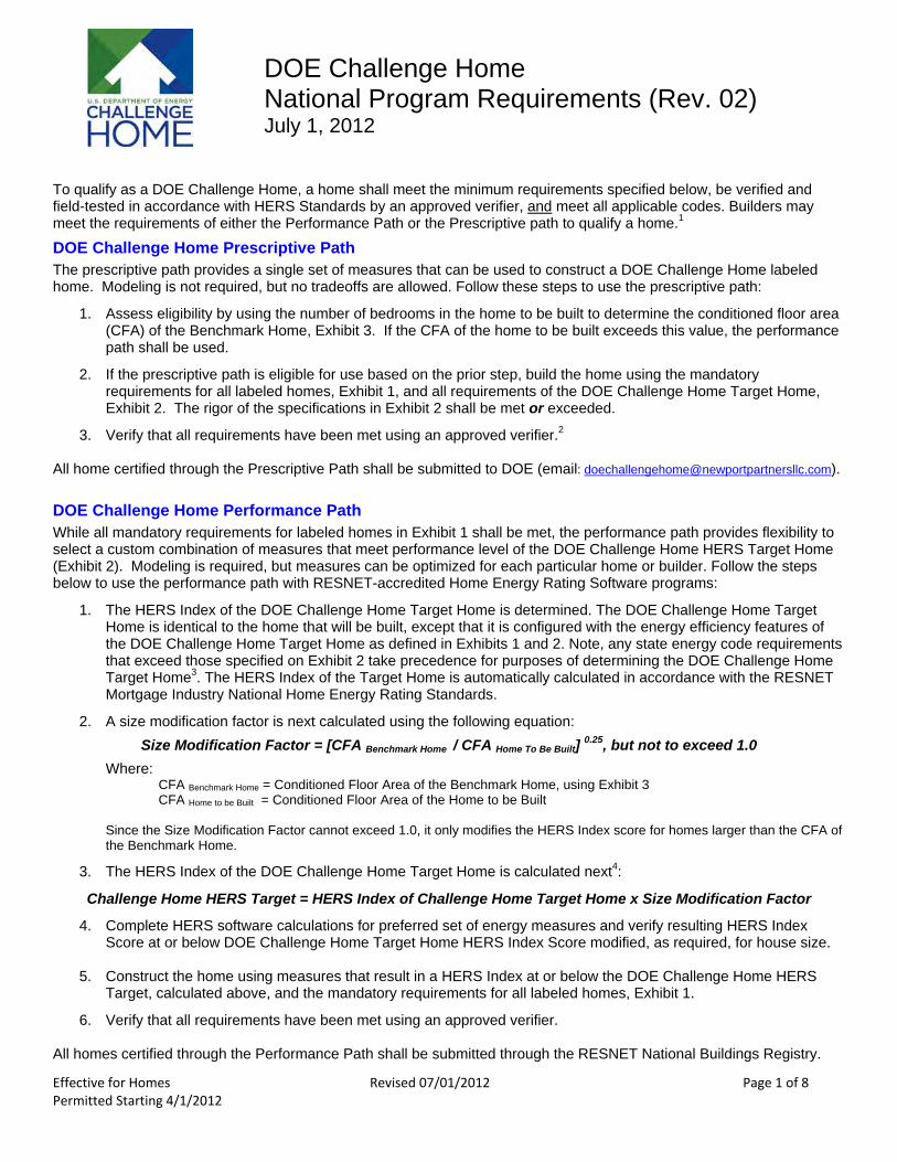
DOE Challenge Home National Program Requirements (Rev. 02) July 1, 2012
To qualify as a DOE Challenge Home, a home shall meet the minimum requirements specified below, be verified and field-tested in accordance with HERS Standards by an approved verifier, and meet all applicable codes. Builders may meet the requirements of either the Performance Path or the Prescriptive path to qualify a home.1
DOE Challenge Home Prescriptive Path The prescriptive path provides a single set of measures that can be used to construct a DOE Challenge Home labeled home. Modeling is not required, but no tradeoffs are allowed. Follow these steps to use the prescriptive path:
1. Assess eligibility by using the number of bedrooms in the home to be built to determine the conditioned floor area (CFA) of the Benchmark Home, Exhibit 3. If the CFA of the home to be built exceeds this value, the performance path shall be used.
2. If the prescriptive path is eligible for use based on the prior step, build the home using the mandatory requirements for all labeled homes, Exhibit 1, and all requirements of the DOE Challenge Home Target Home, Exhibit 2. The rigor of the specifications in Exhibit 2 shall be met or exceeded.
3. Verify that all requirements have been met using an approved verifier.2
All home certified through the Prescriptive Path shall be submitted to DOE (email: [email protected]).
DOE Challenge Home Performance Path While all mandatory requirements for labeled homes in Exhibit 1 shall be met, the performance path provides flexibility to select a custom combination of measures that meet performance level of the DOE Challenge Home HERS Target Home (Exhibit 2). Modeling is required, but measures can be optimized for each particular home or builder. Follow the steps below to use the performance path with RESNET-accredited Home Energy Rating Software programs:
1. The HERS Index of the DOE Challenge Home Target Home is determined. The DOE Challenge Home Target Home is identical to the home that will be built, except that it is configured with the energy efficiency features of the DOE Challenge Home Target Home as defined in Exhibits 1 and 2. Note, any state energy code requirements that exceed those specified on Exhibit 2 take precedence for purposes of determining the DOE Challenge Home Target Home3. The HERS Index of the Target Home is automatically calculated in accordance with the RESNET Mortgage Industry National Home Energy Rating Standards.
2. A size modification factor is next calculated using the following equation: Size Modification Factor = [CFA Benchmark Home / CFA Home To Be Built]
0.25, but not to exceed 1.0
Where: CFA Benchmark Home = Conditioned Floor Area of the Benchmark Home, using Exhibit 3 CFA Home to be Built = Conditioned Floor Area of the Home to be Built
Since the Size Modification Factor cannot exceed 1.0, it only modifies the HERS Index score for homes larger than the CFA of the Benchmark Home.
3. The HERS Index of the DOE Challenge Home Target Home is calculated next4:
Challenge Home HERS Target = HERS Index of Challenge Home Target Home x Size Modification Factor
4. Complete HERS software calculations for preferred set of energy measures and verify resulting HERS Index Score at or below DOE Challenge Home Target Home HERS Index Score modified, as required, for house size.
5. Construct the home using measures that result in a HERS Index at or below the DOE Challenge Home HERS Target, calculated above, and the mandatory requirements for all labeled homes, Exhibit 1.
6. Verify that all requirements have been met using an approved verifier.
All homes certified through the Performance Path shall be submitted through the RESNET National Buildings Registry.
Effective for Homes Revised 07/01/2012 Page 1 of 8 Permitted Starting 4/1/2012
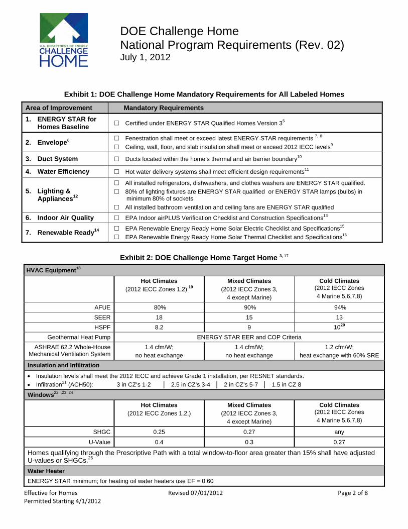
DOE Challenge Home National Program Requirements (Rev. 02) July 1, 2012
Exhibit 1: DOE Challenge Home Mandatory Requirements for All Labeled Homes
Area of Improvement Mandatory Requirements 1. ENERGY STAR for
Homes Baseline □ Certified under ENERGY STAR Qualified Homes Version 35
2. Envelope6 □ Fenestration shall meet or exceed latest ENERGY STAR requirements 7, 8
□ Ceiling, wall, floor, and slab insulation shall meet or exceed 2012 IECC levels9
3. Duct System □ Ducts located within the home’s thermal and air barrier boundary10
4. Water Efficiency □ Hot water delivery systems shall meet efficient design requirements11
5. Lighting & Appliances12
□ All installed refrigerators, dishwashers, and clothes washers are ENERGY STAR qualified. □ 80% of lighting fixtures are ENERGY STAR qualified or ENERGY STAR lamps (bulbs) in
minimum 80% of sockets □ All installed bathroom ventilation and ceiling fans are ENERGY STAR qualified
6. Indoor Air Quality □ EPA Indoor airPLUS Verification Checklist and Construction Specifications13
7. Renewable Ready14 □ EPA Renewable Energy Ready Home Solar Electric Checklist and Specifications15
□ EPA Renewable Energy Ready Home Solar Thermal Checklist and Specifications16
Exhibit 2: DOE Challenge Home Target Home 3, 17
HVAC Equipment18
Hot Climates (2012 IECC Zones 1,2) 19
Mixed Climates (2012 IECC Zones 3,
4 except Marine)
Cold Climates (2012 IECC Zones 4 Marine 5,6,7,8)
AFUE 80% 90% 94% SEER 18 15 13 HSPF 8.2 9 1020
Geothermal Heat Pump ENERGY STAR EER and COP Criteria ASHRAE 62.2 Whole-House
Mechanical Ventilation System 1.4 cfm/W;
no heat exchange 1.4 cfm/W;
no heat exchange 1.2 cfm/W;
heat exchange with 60% SRE Insulation and Infiltration
Insulation levels shall meet the 2012 IECC and achieve Grade 1 installation, per RESNET standards. Infiltration21 (ACH50): 3 in CZ’s 1-2 │ 2.5 in CZ’s 3-4 │ 2 in CZ’s 5-7 │ 1.5 in CZ 8
Windows22, ,23, 24
Hot Climates (2012 IECC Zones 1,2,)
Mixed Climates (2012 IECC Zones 3,
4 except Marine)
Cold Climates (2012 IECC Zones 4 Marine 5,6,7,8)
SHGC 0.25 0.27 any
U-Value 0.4 0.3 0.27
Homes qualifying through the Prescriptive Path with a total window-to-floor area greater than 15% shall have adjusted U-values or SHGCs.25
Water Heater ENERGY STAR minimum; for heating oil water heaters use EF = 0.60
Effective for Homes Revised 07/01/2012 Page 2 of 8 Permitted Starting 4/1/2012
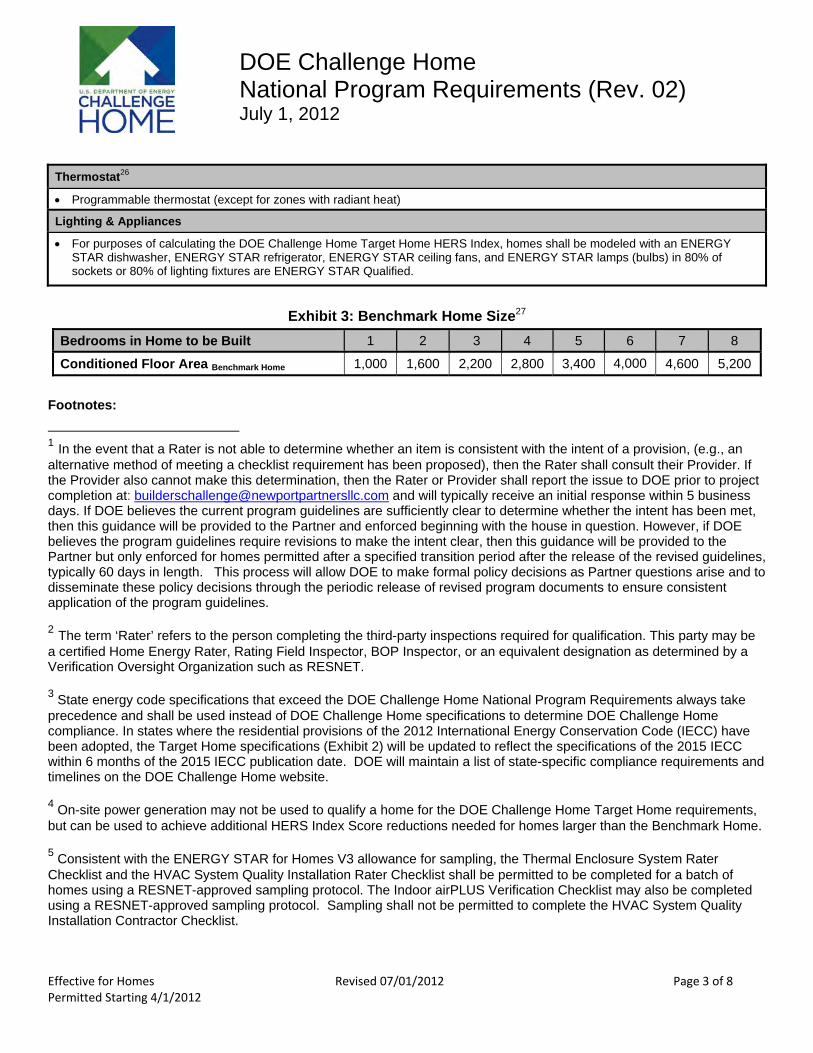
DOE Challenge Home National Program Requirements (Rev. 02) July 1, 2012
Thermostat26
Programmable thermostat (except for zones with radiant heat)
Lighting & Appliances
For purposes of calculating the DOE Challenge Home Target Home HERS Index, homes shall be modeled with an ENERGY STAR dishwasher, ENERGY STAR refrigerator, ENERGY STAR ceiling fans, and ENERGY STAR lamps (bulbs) in 80% of sockets or 80% of lighting fixtures are ENERGY STAR Qualified.
Exhibit 3: Benchmark Home Size27
Bedrooms in Home to be Built 1 2 3 4 5 6 7 8
Conditioned Floor Area Benchmark Home 1,000 1,600 2,200 2,800 3,400 4,000 4,600 5,200
Footnotes:
1 In the event that a Rater is not able to determine whether an item is consistent with the intent of a provision, (e.g., an alternative method of meeting a checklist requirement has been proposed), then the Rater shall consult their Provider. If the Provider also cannot make this determination, then the Rater or Provider shall report the issue to DOE prior to project completion at: [email protected] and will typically receive an initial response within 5 business days. If DOE believes the current program guidelines are sufficiently clear to determine whether the intent has been met, then this guidance will be provided to the Partner and enforced beginning with the house in question. However, if DOE believes the program guidelines require revisions to make the intent clear, then this guidance will be provided to the Partner but only enforced for homes permitted after a specified transition period after the release of the revised guidelines, typically 60 days in length. This process will allow DOE to make formal policy decisions as Partner questions arise and to disseminate these policy decisions through the periodic release of revised program documents to ensure consistent application of the program guidelines.
2 The term ‘Rater’ refers to the person completing the third-party inspections required for qualification. This party may be a certified Home Energy Rater, Rating Field Inspector, BOP Inspector, or an equivalent designation as determined by a Verification Oversight Organization such as RESNET.
3 State energy code specifications that exceed the DOE Challenge Home National Program Requirements always take precedence and shall be used instead of DOE Challenge Home specifications to determine DOE Challenge Home compliance. In states where the residential provisions of the 2012 International Energy Conservation Code (IECC) have been adopted, the Target Home specifications (Exhibit 2) will be updated to reflect the specifications of the 2015 IECC within 6 months of the 2015 IECC publication date. DOE will maintain a list of state-specific compliance requirements and timelines on the DOE Challenge Home website.
4 On-site power generation may not be used to qualify a home for the DOE Challenge Home Target Home requirements, but can be used to achieve additional HERS Index Score reductions needed for homes larger than the Benchmark Home.
5 Consistent with the ENERGY STAR for Homes V3 allowance for sampling, the Thermal Enclosure System Rater Checklist and the HVAC System Quality Installation Rater Checklist shall be permitted to be completed for a batch of homes using a RESNET-approved sampling protocol. The Indoor airPLUS Verification Checklist may also be completed using a RESNET-approved sampling protocol. Sampling shall not be permitted to complete the HVAC System Quality Installation Contractor Checklist.
Effective for Homes Revised 07/01/2012 Page 3 of 8 Permitted Starting 4/1/2012
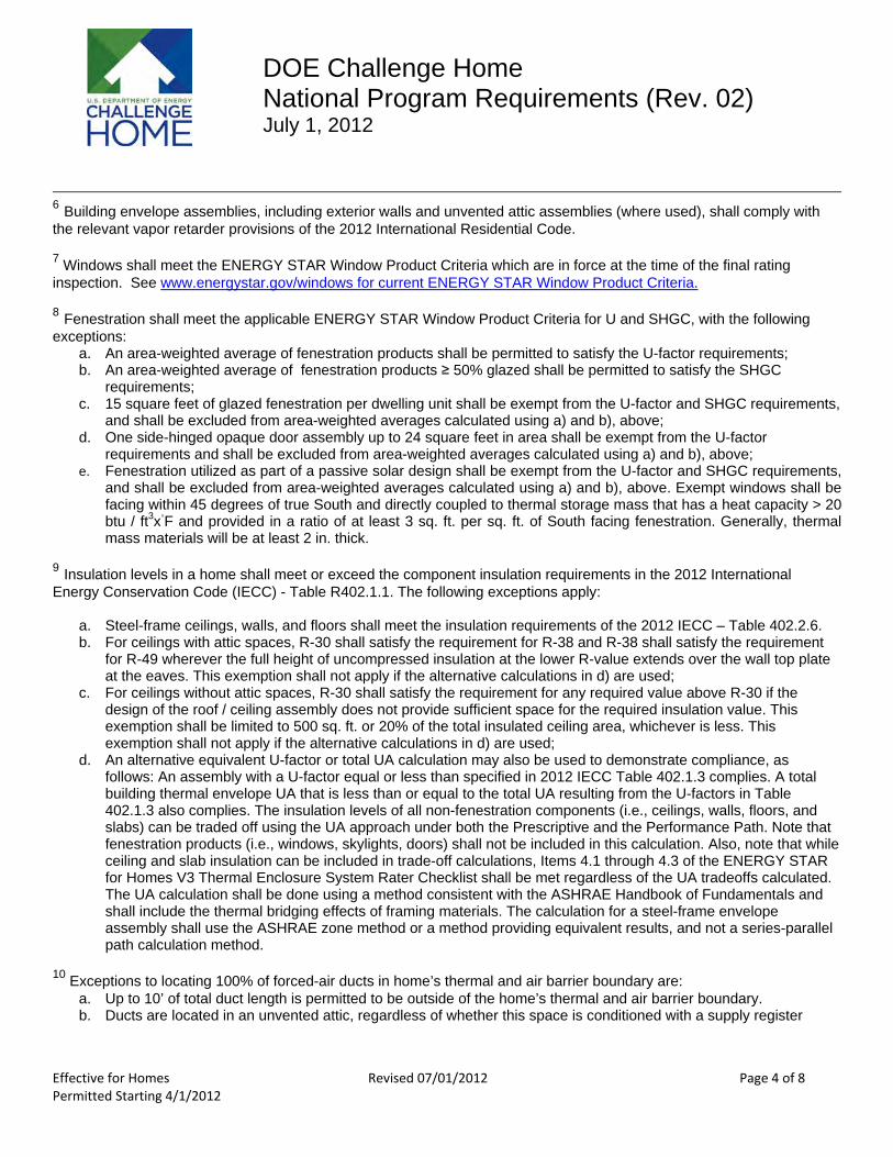
DOE Challenge Home National Program Requirements (Rev. 02) July 1, 2012
6 Building envelope assemblies, including exterior walls and unvented attic assemblies (where used), shall comply with the relevant vapor retarder provisions of the 2012 International Residential Code.
7 Windows shall meet the ENERGY STAR Window Product Criteria which are in force at the time of the final rating inspection. See www.energystar.gov/windows for current ENERGY STAR Window Product Criteria.
8 Fenestration shall meet the applicable ENERGY STAR Window Product Criteria for U and SHGC, with the following exceptions:
a. An area-weighted average of fenestration products shall be permitted to satisfy the U-factor requirements; b. An area-weighted average of fenestration products ≥ 50% glazed shall be permitted to satisfy the SHGC
requirements; c. 15 square feet of glazed fenestration per dwelling unit shall be exempt from the U-factor and SHGC requirements,
and shall be excluded from area-weighted averages calculated using a) and b), above; d. One side-hinged opaque door assembly up to 24 square feet in area shall be exempt from the U-factor
requirements and shall be excluded from area-weighted averages calculated using a) and b), above; e. Fenestration utilized as part of a passive solar design shall be exempt from the U-factor and SHGC requirements,
and shall be excluded from area-weighted averages calculated using a) and b), above. Exempt windows shall be facing within 45 degrees of true South and directly coupled to thermal storage mass that has a heat capacity > 20 btu / ft3x◦F and provided in a ratio of at least 3 sq. ft. per sq. ft. of South facing fenestration. Generally, thermal mass materials will be at least 2 in. thick.
9 Insulation levels in a home shall meet or exceed the component insulation requirements in the 2012 International Energy Conservation Code (IECC) - Table R402.1.1. The following exceptions apply:
a. Steel-frame ceilings, walls, and floors shall meet the insulation requirements of the 2012 IECC – Table 402.2.6. b. For ceilings with attic spaces, R-30 shall satisfy the requirement for R-38 and R-38 shall satisfy the requirement
for R-49 wherever the full height of uncompressed insulation at the lower R-value extends over the wall top plate at the eaves. This exemption shall not apply if the alternative calculations in d) are used;
c. For ceilings without attic spaces, R-30 shall satisfy the requirement for any required value above R-30 if the design of the roof / ceiling assembly does not provide sufficient space for the required insulation value. This exemption shall be limited to 500 sq. ft. or 20% of the total insulated ceiling area, whichever is less. This exemption shall not apply if the alternative calculations in d) are used;
d. An alternative equivalent U-factor or total UA calculation may also be used to demonstrate compliance, as follows: An assembly with a U-factor equal or less than specified in 2012 IECC Table 402.1.3 complies. A total building thermal envelope UA that is less than or equal to the total UA resulting from the U-factors in Table 402.1.3 also complies. The insulation levels of all non-fenestration components (i.e., ceilings, walls, floors, and slabs) can be traded off using the UA approach under both the Prescriptive and the Performance Path. Note that fenestration products (i.e., windows, skylights, doors) shall not be included in this calculation. Also, note that while ceiling and slab insulation can be included in trade-off calculations, Items 4.1 through 4.3 of the ENERGY STAR for Homes V3 Thermal Enclosure System Rater Checklist shall be met regardless of the UA tradeoffs calculated. The UA calculation shall be done using a method consistent with the ASHRAE Handbook of Fundamentals and shall include the thermal bridging effects of framing materials. The calculation for a steel-frame envelope assembly shall use the ASHRAE zone method or a method providing equivalent results, and not a series-parallel path calculation method.
10 Exceptions to locating 100% of forced-air ducts in home’s thermal and air barrier boundary are: a. Up to 10’ of total duct length is permitted to be outside of the home’s thermal and air barrier boundary. b. Ducts are located in an unvented attic, regardless of whether this space is conditioned with a supply register
Effective for Homes Revised 07/01/2012 Page 4 of 8 Permitted Starting 4/1/2012
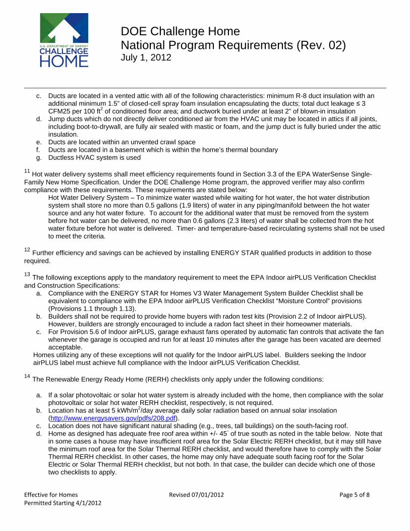
DOE Challenge Home National Program Requirements (Rev. 02) July 1, 2012
c. Ducts are located in a vented attic with all of the following characteristics: minimum R-8 duct insulation with an additional minimum 1.5” of closed-cell spray foam insulation encapsulating the ducts; total duct leakage ≤ 3 CFM25 per 100 ft2 of conditioned floor area; and ductwork buried under at least 2” of blown-in insulation
d. Jump ducts which do not directly deliver conditioned air from the HVAC unit may be located in attics if all joints, including boot-to-drywall, are fully air sealed with mastic or foam, and the jump duct is fully buried under the attic insulation.
e. Ducts are located within an unvented crawl space f. Ducts are located in a basement which is within the home’s thermal boundary g. Ductless HVAC system is used
11 Hot water delivery systems shall meet efficiency requirements found in Section 3.3 of the EPA WaterSense Single-Family New Home Specification. Under the DOE Challenge Home program, the approved verifier may also confirm compliance with these requirements. These requirements are stated below:
Hot Water Delivery System – To minimize water wasted while waiting for hot water, the hot water distribution system shall store no more than 0.5 gallons (1.9 liters) of water in any piping/manifold between the hot water source and any hot water fixture. To account for the additional water that must be removed from the system before hot water can be delivered, no more than 0.6 gallons (2.3 liters) of water shall be collected from the hot water fixture before hot water is delivered. Timer- and temperature-based recirculating systems shall not be used to meet the criteria.
12 Further efficiency and savings can be achieved by installing ENERGY STAR qualified products in addition to those required.
13 The following exceptions apply to the mandatory requirement to meet the EPA Indoor airPLUS Verification Checklist and Construction Specifications:
a. Compliance with the ENERGY STAR for Homes V3 Water Management System Builder Checklist shall be equivalent to compliance with the EPA Indoor airPLUS Verification Checklist “Moisture Control” provisions (Provisions 1.1 through 1.13).
b. Builders shall not be required to provide home buyers with radon test kits (Provision 2.2 of Indoor airPLUS). However, builders are strongly encouraged to include a radon fact sheet in their homeowner materials.
c. For Provision 5.6 of Indoor airPLUS, garage exhaust fans operated by automatic fan controls that activate the fan whenever the garage is occupied and run for at least 10 minutes after the garage has been vacated are deemed acceptable.
Homes utilizing any of these exceptions will not qualify for the Indoor airPLUS label. Builders seeking the Indoor airPLUS label must achieve full compliance with the Indoor airPLUS Verification Checklist.
14 The Renewable Energy Ready Home (RERH) checklists only apply under the following conditions:
a. If a solar photovoltaic or solar hot water system is already included with the home, then compliance with the solar photovoltaic or solar hot water RERH checklist, respectively, is not required.
b. Location has at least 5 kWh/m2/day average daily solar radiation based on annual solar insolation (http://www.energysavers.gov/pdfs/208.pdf).
c. Location does not have significant natural shading (e.g., trees, tall buildings) on the south-facing roof. d. Home as designed has adequate free roof area within +/- 45◦ of true south as noted in the table below. Note that
in some cases a house may have insufficient roof area for the Solar Electric RERH checklist, but it may still have the minimum roof area for the Solar Thermal RERH checklist, and would therefore have to comply with the Solar Thermal RERH checklist. In other cases, the home may only have adequate south facing roof for the Solar Electric or Solar Thermal RERH checklist, but not both. In that case, the builder can decide which one of those two checklists to apply.
Effective for Homes Revised 07/01/2012 Page 5 of 8 Permitted Starting 4/1/2012
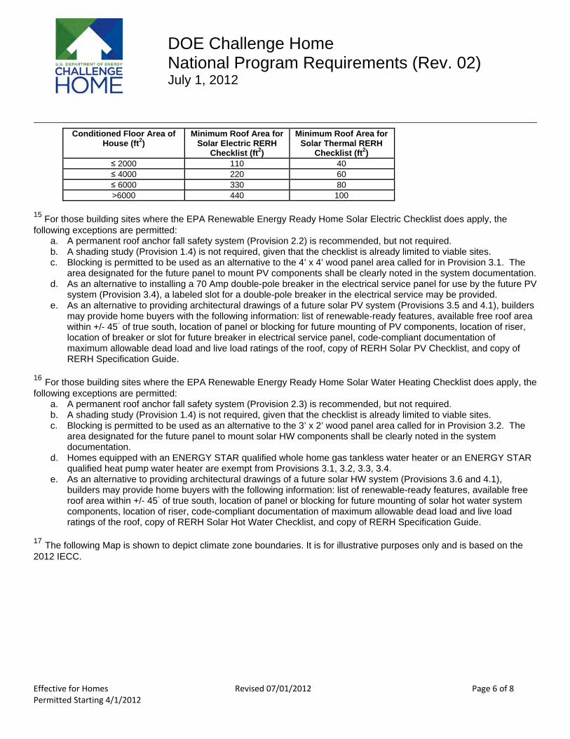
DOE Challenge Home National Program Requirements (Rev. 02) July 1, 2012
Conditioned Floor Area of House (ft2)
Minimum Roof Area for Solar Electric RERH
Checklist (ft2)
Minimum Roof Area for Solar Thermal RERH
Checklist (ft2) ≤ 2000 110 40 ≤ 4000 220 60 ≤ 6000 330 80 >6000 440 100
15 For those building sites where the EPA Renewable Energy Ready Home Solar Electric Checklist does apply, the following exceptions are permitted:
a. A permanent roof anchor fall safety system (Provision 2.2) is recommended, but not required. b. A shading study (Provision 1.4) is not required, given that the checklist is already limited to viable sites. c. Blocking is permitted to be used as an alternative to the 4’ x 4’ wood panel area called for in Provision 3.1. The
area designated for the future panel to mount PV components shall be clearly noted in the system documentation. d. As an alternative to installing a 70 Amp double-pole breaker in the electrical service panel for use by the future PV
system (Provision 3.4), a labeled slot for a double-pole breaker in the electrical service may be provided. e. As an alternative to providing architectural drawings of a future solar PV system (Provisions 3.5 and 4.1), builders
may provide home buyers with the following information: list of renewable-ready features, available free roof area within +/- 45◦ of true south, location of panel or blocking for future mounting of PV components, location of riser, location of breaker or slot for future breaker in electrical service panel, code-compliant documentation of maximum allowable dead load and live load ratings of the roof, copy of RERH Solar PV Checklist, and copy of RERH Specification Guide.
16 For those building sites where the EPA Renewable Energy Ready Home Solar Water Heating Checklist does apply, the following exceptions are permitted:
a. A permanent roof anchor fall safety system (Provision 2.3) is recommended, but not required. b. A shading study (Provision 1.4) is not required, given that the checklist is already limited to viable sites. c. Blocking is permitted to be used as an alternative to the 3’ x 2’ wood panel area called for in Provision 3.2. The
area designated for the future panel to mount solar HW components shall be clearly noted in the system documentation.
d. Homes equipped with an ENERGY STAR qualified whole home gas tankless water heater or an ENERGY STAR qualified heat pump water heater are exempt from Provisions 3.1, 3.2, 3.3, 3.4.
e. As an alternative to providing architectural drawings of a future solar HW system (Provisions 3.6 and 4.1), builders may provide home buyers with the following information: list of renewable-ready features, available free roof area within +/- 45◦ of true south, location of panel or blocking for future mounting of solar hot water system components, location of riser, code-compliant documentation of maximum allowable dead load and live load ratings of the roof, copy of RERH Solar Hot Water Checklist, and copy of RERH Specification Guide.
17 The following Map is shown to depict climate zone boundaries. It is for illustrative purposes only and is based on the 2012 IECC.
Effective for Homes Revised 07/01/2012 Page 6 of 8 Permitted Starting 4/1/2012

DOE Challenge Home National Program Requirements (Rev. 02) July 1, 2012
2012 IECC Climate Zone Map
18 HVAC System Type for the Target Home shall be the same as the Rated Home, with the following exceptions. The Target Home shall be configured with an air-source heat pump in Climate Zones 1-6 when the Rated Home is modeled with a ground-source heat pump, electric strip or baseboard heat; and the Target Home shall be configured with ground-source heat pump in Climate Zones 7 & 8 when the Rated Home is modeled with an air-source or ground-source heat pump, electric strip or baseboard heat. Applicable efficiency levels shall be selected from Exhibit 2.
19 DOE recommends, but does not require, that cooling systems in hot/humid climates utilize controls for immediate blower shutoff after condenser shutoff, to prevent re-evaporation of moisture off the wet coil.
20 Air source heat pumps with electric resistance backup cannot be used in homes qualified in Climate Zones 7 & 8 using the Prescriptive Path.
21 Envelope leakage shall be determined by an approved verifier using a RESNET-approved testing protocol.
22 All decorative glass and skylight window areas count toward the total window area to above-grade conditioned floor area (WFA) ratio.
23 DOE strongly encourages all DOE Challenge Home partners to consider using R-5 windows in cold climates in anticipation of them becoming the state-of-the-art window choice in the near future. Visit the DOE web site (http://www1.eere.energy.gov/buildings/windowsvolumepurchase/) for more details and sources of these windows.
24 For homes using Exhibit 2 for Prescriptive compliance with the DOE Challenge Home, the following exceptions to the U-Value and SHGC requirements in Exhibit 2 apply:
a. An area-weighted average of fenestration products shall be permitted to satisfy the U-factor requirements; b. An area-weighted average of fenestration products ≥ 50% glazed shall be permitted to satisfy the SHGC
requirements; c. 15 square feet of glazed fenestration per dwelling unit shall be exempt from the U-factor and SHGC requirements,
and shall be excluded from area-weighted averages calculated using a) and b), above;
Effective for Homes Revised 07/01/2012 Page 7 of 8 Permitted Starting 4/1/2012
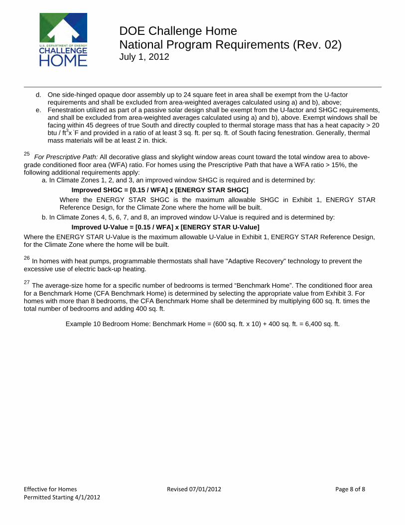
DOE Challenge Home National Program Requirements (Rev. 02) July 1, 2012
d. One side-hinged opaque door assembly up to 24 square feet in area shall be exempt from the U-factor requirements and shall be excluded from area-weighted averages calculated using a) and b), above;
e. Fenestration utilized as part of a passive solar design shall be exempt from the U-factor and SHGC requirements, and shall be excluded from area-weighted averages calculated using a) and b), above. Exempt windows shall be facing within 45 degrees of true South and directly coupled to thermal storage mass that has a heat capacity > 20 btu / ft3x ◦F and provided in a ratio of at least 3 sq. ft. per sq. ft. of South facing fenestration. Generally, thermal mass materials will be at least 2 in. thick.
25 For Prescriptive Path: All decorative glass and skylight window areas count toward the total window area to above-grade conditioned floor area (WFA) ratio. For homes using the Prescriptive Path that have a WFA ratio > 15%, the following additional requirements apply:
a. In Climate Zones 1, 2, and 3, an improved window SHGC is required and is determined by: Improved SHGC = [0.15 / WFA] x [ENERGY STAR SHGC]
Where the ENERGY STAR SHGC is the maximum allowable SHGC in Exhibit 1, ENERGY STAR Reference Design, for the Climate Zone where the home will be built.
b. In Climate Zones 4, 5, 6, 7, and 8, an improved window U-Value is required and is determined by: Improved U-Value = [0.15 / WFA] x [ENERGY STAR U-Value]
Where the ENERGY STAR U-Value is the maximum allowable U-Value in Exhibit 1, ENERGY STAR Reference Design, for the Climate Zone where the home will be built.
26 In homes with heat pumps, programmable thermostats shall have "Adaptive Recovery" technology to prevent the excessive use of electric back-up heating.
27 The average-size home for a specific number of bedrooms is termed “Benchmark Home”. The conditioned floor area for a Benchmark Home (CFA Benchmark Home) is determined by selecting the appropriate value from Exhibit 3. For homes with more than 8 bedrooms, the CFA Benchmark Home shall be determined by multiplying 600 sq. ft. times the total number of bedrooms and adding 400 sq. ft.
Example 10 Bedroom Home: Benchmark Home = (600 sq. ft. x 10) + 400 sq. ft. = 6,400 sq. ft.
Effective for Homes Revised 07/01/2012 Page 8 of 8 Permitted Starting 4/1/2012

Appendix 3
COST ESTIMATE
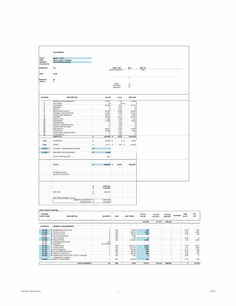
Cost Report
DATE: March 1, 2013 JOB: Oliver Carbon Challenge BUDGET: ACCOUNTING BUDGET PLAN DATE:
ADDENDA: n/a UNIT TYPE QTY UNIT SFBASE DESIGN #0 2 1,890
GSF: 3,780
2MONTHS: 10 UNITS: 2
Baths 4Half Baths n/aBedrooms 6
DIVISION DESCRIPTION VALUE G.S.F. PER UNIT
1 GENERAL REQUIREMENTS 27,437 7.26 13,7182 SITE WORK nic nic nic3 CONCRETE 36,358 9.62 18,1794 MASONRY 0 0.00 05 METALS 0 0.00 06 WOOD AND PLASTIC 86,718 22.94 43,3597 THERMAL AND MOISTURE 41,581 11.00 20,7918 DOORS AND WINDOWS 15,774 4.17 7,8879 FINISHES 60,949 16.12 30,47510 SPECIALTIES 1,350 0.36 67511 EQUIPMENT 17,869 4.73 8,93412 FURNISHINGS 0 0.00 013 SPECIAL CONSTRUCTION 0 0.00 014 CONVEYING SYSTEMS 0 0.00 015 MECHANICAL 48,872 12.93 24,43616 ELECTRICAL 15,380 4.07 7,69017 THIRD PARTY INSPECTIONS 0 0.00 018 ALLOWANCES 0 0.00 0
SUBTOTAL 352,288$ 93.20$ $176,144
3.0% OVERHEAD 10,569$ 3$ 5,284$
6.0% PROFIT 21,137$ 5.59$ 10,569$
17-010 PAYMENT / PERFORMANCE BOND $ -
17-020 BUILDERS RISK INSURANCE 2,540$
COST CERTIFICATION NIC
TOTAL 386,534$ 102.26$ $193,267
NO WAGE SCALESALES TAX APPLIES
2,492,416$ 2,105,882$
HUD 2328 386,534$ -$
PER STEVE MOORE- 1-14-11OWNER LAST BUDGET 2,500,000$
OWNER GOAL 2,200,000$
Oliver Carbon Challenge
DIVISION TOTAL PER PERCOST CODE DESCRIPTION QUANTITY UNIT UNIT PRICE VALUE G.S.F. UNIT
352,288 457,651 206,944 -
DIVISION 1 GENERAL REQUIREMENTS
01-030 M WORKMAN'S FACILITIES 6 MO 50.00 300 - - - 0.08 15001-040 E TRUCK & AUTO 6 MO 600.00 3,600 - - - 0.95 1,80001-040 M TRUCK & AUTO 6 MO 100.00 600 - - - 0.16 30001-045 M AUTO ALLOWANCE 6 MO 0.0001-050 E FIELD OFFICE 6 MO 0.00 0 - - - 0.00 001-050 M FIELD OFFICE 6 MO 1,120.00 6,720 - - - 1.78 3,36001-060 M PROFESSIONAL FEES NIC01-090 M SECURITY BY OWNER01-410 L SUPERVISION 1 MO 8,854.17 8,854 - - - 2.34 4,42701-410 P SUPERVISION 1 MO 5,312.50 5,313 - - - 1.41 2,65601-470 M PHOTOGRAPHS 1 MO 500.00 500 - - - 0.13 25001-475 M PLANS REPRODUCTION 1 MO 200.00 200 - - - 0.05 10001-480 M PROJECT SIGN / HCI 1 EA 850.00 850 - - - 0.22 42501-500 M TEMPORARY FACILITIES- UTILITY USEAGE
CHARGES BY OWNER1 MO 0.00 0 - - - 0.00 0
01-650 M SAFETY PERSONNEL 1 MO 500.00 500 - - - 0.13 250
TOTAL DIVISION 1 10 MO 2,744 27,437 206,944 206,944 - 7 13,718
TARGET BUYOUT
ACTUAL BUYOUT SAVINGS
Draft Carbon Challenge Budget 2 1 3/2/2013
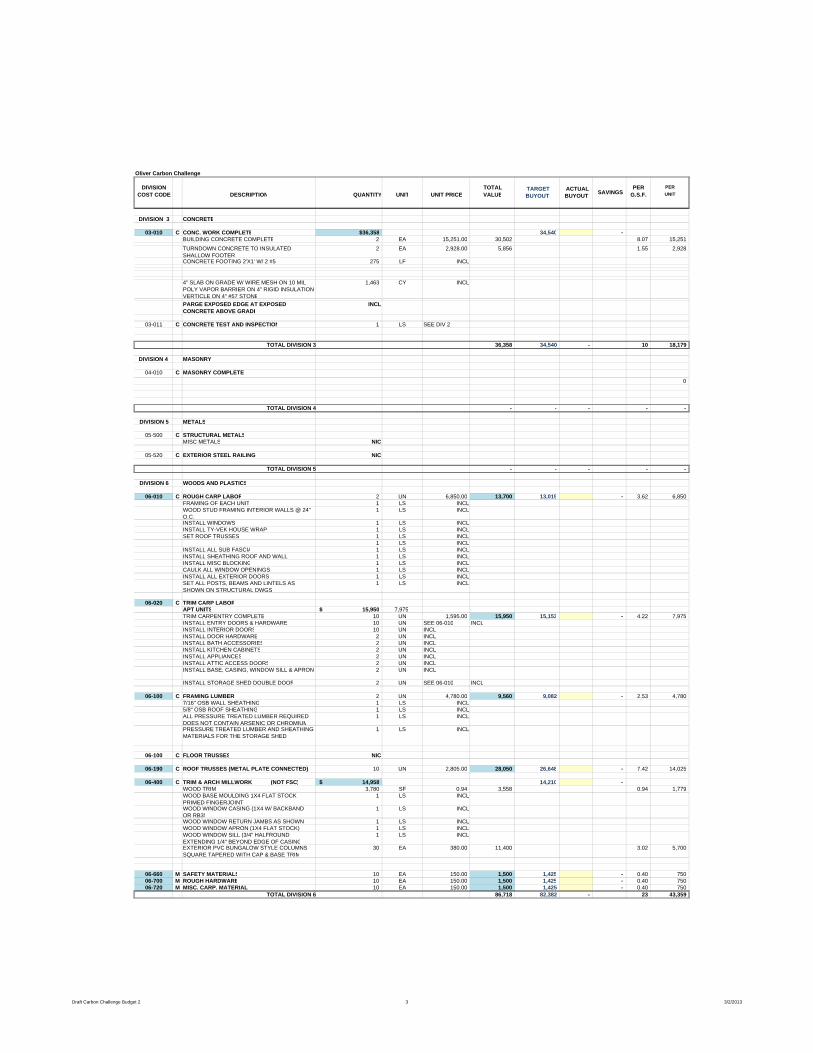
Oliver Carbon Challenge
DIVISION TOTAL PER PERCOST CODE DESCRIPTION QUANTITY UNIT UNIT PRICE VALUE G.S.F. UNIT
TARGET BUYOUT
ACTUAL BUYOUT SAVINGS
DIVISION 3 CONCRETE
03-010 C CONC. WORK COMPLETE $36,358 34,540 -BUILDING CONCRETE COMPLETE 2 EA 15,251.00 30,502 8.07 15,251TURNDOWN CONCRETE TO INSULATED SHALLOW FOOTER
2 EA 2,928.00 5,856 1.55 2,928
CONCRETE FOOTING 2'X1' W/ 2 #5 275 LF INCL
4" SLAB ON GRADE W/ WIRE MESH ON 10 MIL POLY VAPOR BARRIER ON 4" RIGID INSULATION VERTICLE ON 4" #57 STONE
1,463 CY INCL
PARGE EXPOSED EDGE AT EXPOSED CONCRETE ABOVE GRADE
INCL
03-011 C CONCRETE TEST AND INSPECTION 1 LS SEE DIV 2
TOTAL DIVISION 3 36,358 34,540 - 10 18,179
DIVISION 4 MASONRY
04-010 C MASONRY COMPLETE0
TOTAL DIVISION 4 - - - - -
DIVISION 5 METALS
05-500 C STRUCTURAL METALSMISC METALS NIC
05-520 C EXTERIOR STEEL RAILING NIC
TOTAL DIVISION 5 - - - - -
DIVISION 6 WOODS AND PLASTICS
06-010 C ROUGH CARP LABOR 2 UN 6,850.00 13,700 13,015 - 3.62 6,850FRAMING OF EACH UNIT 1 LS INCLWOOD STUD FRAMING INTERIOR WALLS @ 24" O.C.
1 LS INCL
INSTALL WINDOWS 1 LS INCLINSTALL TY-VEK HOUSE WRAP 1 LS INCLSET ROOF TRUSSES 1 LS INCL
1 LS INCLINSTALL ALL SUB FASCIA 1 LS INCLINSTALL SHEATHING ROOF AND WALL 1 LS INCLINSTALL MISC BLOCKING 1 LS INCLCAULK ALL WINDOW OPENINGS 1 LS INCLINSTALL ALL EXTERIOR DOORS 1 LS INCLSET ALL POSTS, BEAMS AND LINTELS AS SHOWN ON STRUCTURAL DWGS
1 LS INCL
06-020 C TRIM CARP LABOR
APT UNITS 15,950$ 7,975TRIM CARPENTRY COMPLETE 10 UN 1,595.00 15,950 15,153 - 4.22 7,975INSTALL ENTRY DOORS & HARDWARE 10 UN SEE 06-010 INCLINSTALL INTERIOR DOORS 10 UN INCLINSTALL DOOR HARDWARE 2 UN INCLINSTALL BATH ACCESSORIES 2 UN INCLINSTALL KITCHEN CABINETS 2 UN INCLINSTALL APPLIANCES 2 UN INCLINSTALL ATTIC ACCESS DOORS 2 UN INCLINSTALL BASE, CASING, WINDOW SILL & APRON 2 UN INCL
INSTALL STORAGE SHED DOUBLE DOOR 2 UN SEE 06-010 INCL
06-100 C FRAMING LUMBER 2 UN 4,780.00 9,560 9,082 - 2.53 4,7807/16" OSB WALL SHEATHING 1 LS INCL5/8" OSB ROOF SHEATHING 1 LS INCLALL PRESSURE TREATED LUMBER REQUIRED DOES NOT CONTAIN ARSENIC OR CHROMIUM
1 LS INCL
PRESSURE TREATED LUMBER AND SHEATHING MATERIALS FOR THE STORAGE SHED
1 LS INCL
06-100 C FLOOR TRUSSES NIC
06-190 C ROOF TRUSSES (METAL PLATE CONNECTED) 10 UN 2,805.00 28,050 26,648 - 7.42 14,025
06-400 C TRIM & ARCH MILLWORK (NOT FSC) 14,958$ 14,210 -WOOD TRIM 3,780 SF 0.94 3,558 0.94 1,779WOOD BASE MOULDING 1X4 FLAT STOCK PRIMED FINGERJOINT
1 LS INCL
WOOD WINDOW CASING (1X4 W/ BACKBAND OR RB3)
1 LS INCL
WOOD WINDOW RETURN JAMBS AS SHOWN 1 LS INCLWOOD WINDOW APRON (1X4 FLAT STOCK) 1 LS INCLWOOD WINDOW SILL (3/4" HALFROUND EXTENDING 1/4" BEYOND EDGE OF CASING
1 LS INCL
EXTERIOR PVC BUNGALOW STYLE COLUMNS SQUARE TAPERED WITH CAP & BASE TRIM
30 EA 380.00 11,400 3.02 5,700
06-660 M SAFETY MATERIALS 10 EA 150.00 1,500 1,425 - 0.40 75006-700 M ROUGH HARDWARE 10 EA 150.00 1,500 1,425 - 0.40 75006-720 M MISC. CARP. MATERIAL 10 EA 150.00 1,500 1,425 - 0.40 750
TOTAL DIVISION 6 86,718 82,382 - 23 43,359
Draft Carbon Challenge Budget 2 3 3/2/2013
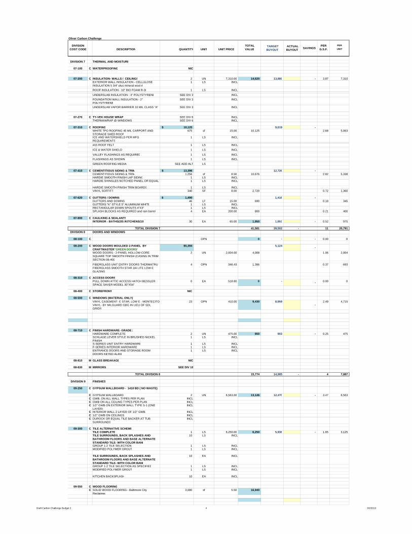
Oliver Carbon Challenge
DIVISION TOTAL PER PERCOST CODE DESCRIPTION QUANTITY UNIT UNIT PRICE VALUE G.S.F. UNIT
TARGET BUYOUT
ACTUAL BUYOUT SAVINGS
DIVISION 7 THERMAL AND MOISTURE
07-100 C WATERPROOFING NIC
07-200 C INSULATION- WALLS / CEILINGS 2 UN 7,310.00 14,620 13,889 - 3.87 7,310EXTERIOR WALL INSULATION - CELLULOSE INSULATION 5 3/4" plus mineral wool 4
1 LS INCL
ROOF INSULATION - 10" BIO FOAM R-38 1 LS INCL
UNDERSLAB INSULATION - 4" POLYSTYRENE SEE DIV 3 INCLFOUNDATION WALL INSULATION - 2" POLYSTYRENE
SEE DIV 3 INCL
UNDERSLAB VAPOR BARRIER 10 MIL CLASS "A" SEE DIV 3 INCL
07-270 C TY-VEK HOUSE WRAP SEE DIV 6 INCLTHERMAWRAP @ WINDOWS SEE DIV 6 INCL
07-310 C ROOFING 10,125$ 9,619 -WHITE TPO ROOFING 45 MIL CARPORT AND STORAGE SHED ROOF
675 sf 15.00 10,125 2.68 5,063
ICE AND WATERSHIELD PER MFG REQUIREMENTS
1 LS INCL
#15 ROOF FELT 1 LS INCL
ICE & WATER SHIELD 1 LS INCL
VALLEY FLASHINGS AS REQUIRED 1 LS INCLFLASHINGS AS SHOWN 1 LS INCLGREEN ROOFING MEDIA SEE ADD ALT LS
07-410 C CEMENTITIOUS SIDING & TRIM 13,396$ 12,726 -CEMENTITIOUS SIDING & TRIM 1,256 sf 8.50 10,676 2.82 5,338HARDIE SMOOTH FINISH LAP SIDING 1 LS INCLHARDIE SHINGLES NOTCHED PANEL OR EQUAL 1 LS INCL
HARDIE SMOOTH FINISH TRIM BOARDS 1 LS INCLVINYL SOFFITT 340 SF 8.00 2,720 0.72 1,360
07-620 C GUTTERS / DOWNS 1,490$ 1,416 -GUTTERS AND DOWNS 46 LF 15.00 690 0.18 345GUTTERS "K" STYLE 5" ALUMINUM WHITE 1 LS INCLRECTANGULAR DOWN SPOUTS 4"X3" 1 LS INCLSPLASH BLOCKS AS REQUIRED and rain barrels 4 EA 200.00 800 0.21 400
07-900 C CAULKING & SEALANTSINTERIOR - BATHS(20) /KITCHENS(10 30 EA 65.00 1,950 1,853 - 0.52 975
TOTAL DIVISION 7 41,581 39,502 - 11 20,791 DIVISION 8 DOORS AND WINDOWS
08-100 C OPN 0 - - 0.00 0
08-200 C WOOD DOORS MOULDED 2-PANEL BY CRAFTMASTER "GREEN DOORS"
$5,394 5,124 -
WOOD DOORS - 2-PANEL HOLLOW-CORE SQUARE TOP SMOOTH FINISH (CASING IN TRIM SECTION 06-400
2 UN 2,004.00 4,008 1.06 2,004
FIBERGLASS UNIT ENTRY DOORS THERMATRU FIBERGLASS SMOOTH STAR 3/4 LITE LOW-E GLAZING
4 OPN 346.43 1,386 0.37 693
08-310 C ACCESS DOORSPULL DOWN ATTIC ACCESS HATCH BESSLER SPACE SAVER MODEL 30"X54"
0 EA 518.80 0 - - 0.00 0
08-400 C STOREFRONT NIC
08-500 C WINDOWS (MATERIAL ONLY) VINYL CASEMENT- E STAR, LOW E - MONTECITO VINYL- BY MILGUARD GBG IN LIEU OF SDL GRIDS
23 OPN 410.00 9,430 8,959 -
2.49 4,715
08-710 C FINISH HARDWARE- GRADE 2HARDWARE COMPLETE 2 UN 475.00 950 903 - 0.25 475SCHLAGE LEVER STYLE IN BRUSHED NICKEL FINISH
1 LS INCL
S-SERIES UNIT ENTRY HARDWARE 1 LS INCLF-SERIES INTERIOR HARDWARE 1 LS INCLENTRANCE DOORS AND STORAGE ROOM DOORS KEYED ALIKE
1 LS INCL
08-810 M GLASS BREAKAGE NIC
08-830 M MIRRORS SEE DIV 10
TOTAL DIVISION 8 15,774 14,985 - 4 7,887
DIVISION 9 FINISHES
09-250 C GYPSUM WALLBOARD - 1418 BD ( NO WASTE)
C GYPSUM WALLBOARD 2 UN 6,563.00 13,126 12,470 - 3.47 6,563C GWB. ON ALL WALL TYPES PER PLAN INCLC GWB ON ALL CEILING TYPES PER PLAN INCLC 1/2" GWB ON EXTERIOR WALL TYPE S-1 (ONE
LAYER)INCL
C INTERIOR WALL 2 LAYER OF 1/2" GWB. INCLC 1/2" GWB ON CEILINGS INCLC DUROCK OR EQUAL TILE BACKER AT TUB
SURROUNDSINCL
09-300 C TILE ALTERNATIVE SCHEMETILE COMPLETE 1 LS 6,250.00 6,250 5,938 - 1.65 3,125TILE SURROUNDS, BACK SPLASHES AND BATHROOM FLOORS AND BASE ALTERNATE STANDARD TILE- WITH COLOR BAND
10 LS INCL
GROUP 1-2 TILE SELECTION 1 LS INCLMODIFIED POLYMER GROUT 1 LS INCL
TILE SURROUNDS, BACK SPLASHES AND BATHROOM FLOORS AND BASE ALTERNATE STANDARD TILE- WITH COLOR BAND
10 EA INCL
GROUP 1-2 TILE SELECTION AS SPECIFIED 1 LS INCLMODIFIED POLYMER GROUT 1 LS INCL
KITCHEN BACKSPLASH 10 EA INCL
09-550 C WOOD FLOORINGC SOLID WOOD FLOORING - Baltimore City
Reclaimed3,080 sf 5.50 16,940
Draft Carbon Challenge Budget 2 4 3/2/2013
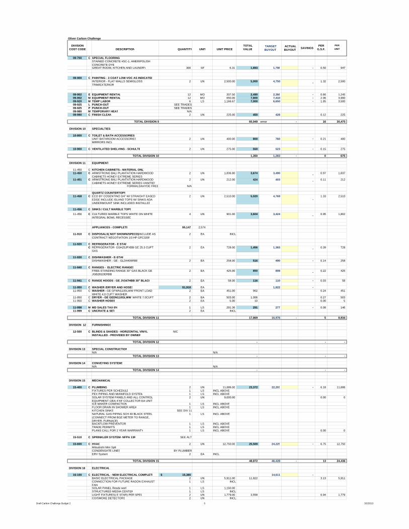
Oliver Carbon Challenge
DIVISION TOTAL PER PERCOST CODE DESCRIPTION QUANTITY UNIT UNIT PRICE VALUE G.S.F. UNIT
TARGET BUYOUT
ACTUAL BUYOUT SAVINGS
09-700 C SPECIAL FLOORING STAINED CONCRETE #SC-1; AMERIPOLISH CONCRETE DYEGREAT ROOM, KITCHEN AND LAUNDRY 300 SF 6.31 1,893 1,798 - 0.50 947
09-900 C PAINTING - 3 COAT LOW-VOC AS INDICATEDINTERIOR - FLAT WALLS SEMIGLOSS TRIM/EXTERIOR
2 UN 2,500.00 5,000 4,750 - 1.32 2,500
09-902 E EQUIPMENT RENTAL 12 MO 207.50 2,490 2,366 - 0.66 1,24509-902 M EQUIPMENT RENTAL 12 MO 650.00 7,800 7,410 - 2.06 3,90009-920 M TEMP LABOR 6 LS 1,166.67 7,000 6,650 - 1.85 3,50009-925 L PUNCH-OUT SEE TRADES09-925 P PUNCH-OUT SEE TRADES09-980 M TEMPORARY HEAT N/A09-990 C FINISH CLEAN 2 UN 225.00 450 428 0.12 225
TOTAL DIVISION 9 60,949 error - 16 30,475
DIVISION 10 SPECIALTIES-
10-800 C TOILET & BATH ACCESSORIES UNIT BATHROOM ACCESSORIES 2 UN 400.00 800 760 - 0.21 400MIRRORS INCL
10-900 C VENTILATED SHELVING - SCHULTE 2 UN 275.00 550 523 - 0.15 275
TOTAL DIVISION 10 1,350 1,283 - 0 675
DIVISION 11 EQUIPMENT
11-450 C KITCHEN CABINETS-- MATERIAL ONLY11-450 C ARMSTRONG BALI PLANTATION HARDWOOD
CABINETS HONEY EXTREME SERIES 2 UN 1,836.80 3,674 3,490 - 0.97 1,837
11-451 C ARMSTRONG BALI PLANTATION HARDWOOD CABINETS HONEY EXTREME SERIES VANITIES
2 UN 212.00 424 403 - 0.11 212
FORMALDAHYDE FREE N/A
QUARTZ COUNTERTOPS11-458 C ECO BY COSENTINO 3/4" W/ STRAIGHT EASED
EDGE INCLUDE ISLAND TOPS W/ SINKS ADA UNDERMOUNT SINK INCLUDED INSTALLED
2 UN 2,510.00 5,020 4,769 -
1.33 2,510
11-456 C SINKS / CULT MARBLE TOPS11-456 C CULTURED MARBLE TOPS WHITE ON WHITE
INTEGRAL BOWL RECESSED4 UN 901.00 3,604 3,424 - 0.95 1,802
APPLIANCES - COMPLETE $5,147 2,574
11-910 C DISPOSALS( NOT SHOWN/SPECD) INCLUDE AS CONTRACT NEGOTIATION 1/3 HP GFC320F
2 EA INCL
11-920 C REFRIGERATOR - E STARC REFRIGERATOR- GSH25JFXBB GE 25.3 CUFT
SXS2 EA 728.00 1,456 1,383 - 0.39 728
11-930 C DISHWASHER - E-STARDISHWASHER - GE - GLD4406RBB 2 EA 258.00 516 490 - 0.14 258
11-940 C RANGES - ELECTRIC RANGESFREE-STANDING RANGE 30" GAS BLACK GE JGB281DERBB
2 EA 425.00 850 808 - 0.22 425
11-941 C RANGE HOODS - GE JV347HBB 30" BLACK 2 EA 58.00 116 110 - 0.03 58
11-950 C WASHER /DRYER AND HOSES $1,918 EA 1,822 -11-950 C WASHER - GE GFWN1100LWW FRONT LOAD
WHITE 4.0 CUFT WASHER2 EA 451.00 902 0.24 451
11-950 C DRYER - GE GEDN110GLWW WHITE 7.0CUFT 2 EA 503.00 1,006 0.27 50311-950 C WASHER HOSES 2 EA 5.00 10 0.00 5
11-998 M MD SALES TAX 6% 1 LS 291.36 291 277 - 0.08 14611-999 C UNCRATE & SET 2 EA INCL
. TOTAL DIVISION 11 17,869 16,976 - 5 8,934
DIVISION 12 FURNISHINGS
12-500 C BLINDS & SHADES - HORIZONTAL VINYL INSTALLED - PROVIDED BY OWNER
NIC
TOTAL DIVISION 12 - - -
DIVISION 13 SPECIAL CONSTRUCTIONN/A N/A
TOTAL DIVISION 13 - - -
DIVISION 14 CONVEYING SYSTEMSN/A N/A
TOTAL DIVISION 14 - - -
DIVISION 15 MECHANICAL
15-400 C PLUMBING 2 UN 11,686.00 23,372 22,203 - 6.18 11,686FIXTURES PER SCHEDULE 1 LS INCL ABOVEPEX PIPING AND MIANIFOLD SYSTEM 1 LS INCL ABOVESOLAR SYSTEM PANELS AND ALL CONTROL EQUIPMENT (2EA 4'X8' COLLECTOR EA UNIT)
2 UN 9,000.00 0.00 0
ICE MAKER CONENCTION 1 LS INCL ABOVEFLOOR DRAIN IN SHOWER AREA 1 LS INCL ABOVEKITCHEN SINKS SEE DIV 11NATURAL GAS PIPING SCH 40 BLACK STEEL (CONNECT FROM BGE METER TO RANGE, DRYER, FURNACE)
1 LS INCL ABOVE
BACKFLOW PREVENTOR 1 LS INCL ABOVETRADE PERMITS 1 LS INCL ABOVEPLANS CALL FOR 2 YEAR WARRANTY 1 LS INCL ABOVE 0.00 0
15-510 C SPRINKLER SYSTEM- NFPA 13R SEE ALT
15-600 C HVAC 2 UN 12,750.00 25,500 24,225 - 6.75 12,750Mitsubishi Mini SplitCONDENSATE LINES BY PLUMBERERV System 2 EA INCL
TOTAL DIVISION 15 48,872 46,428 - 13 24,436
DIVISION 16 ELECTRICAL
16-100 C ELECTRICAL - NEW ELECTRICAL COMPLETE 15,380$ 14,611 -BASIC ELECTRICAL PACKAGE 2 UN 5,911.00 11,822 3.13 5,911CONNECTION FOR FUTURE RADON EXHAUST FAN
1 LS INCL
SOLAR PANEL Ready work 1 LS 1,150.00STRUCTURED MEDIA CENTER 1 LS INCLLIGHT FIXTURES( E STAR) PER SPEC 2 UN 1,779.00 3,558 0.94 1,779CO/SMOKE DETECTORS 2 UN INCL
Draft Carbon Challenge Budget 2 5 3/2/2013
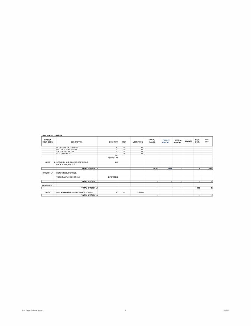
Oliver Carbon Challenge
DIVISION TOTAL PER PERCOST CODE DESCRIPTION QUANTITY UNIT UNIT PRICE VALUE G.S.F. UNIT
TARGET BUYOUT
ACTUAL BUYOUT SAVINGS
DOOR CHIME AS SHOWN 2 UN INCLGFI CIRCUTS AS SHOWN 2 UN INCLARC FAULT CIRCUTS 2 UN INCLVOICE.DATA.CATV 2 UN INCL
NICADD ALT #9
16-100 C SECURITY AND ACCESS CONTROL- 6 LOCATIONS- KEY FOB
NIC
TOTAL DIVISION 16 15,380 14,611 - 4 7,690
DIVISION 17 BONDS,PERMITS,CHGS.
THIRD PARTY INSPECTIONS BY OWNER
TOTAL DIVISION 17 - - - - -
DIVISION 18 TOTAL DIVISION 18 - - - 0.00 0
19-009 ADD ALTERNATE #9 - FIRE ALARM SYSTEM 1 UN 4,833.00 TOTAL DIVISION 19 - - -
Draft Carbon Challenge Budget 2 6 3/2/2013