SLIDING DOOR OPERATOR
14
WARNING: Do not use the device without referring to this manual first. WIND SLIDING DOOR OPERATOR Technical Manual P09530 - 09/2021 Rev. 0 Fabricado por: Motoppar Indústria e Comércio de Automatizadores Ltda Av. Dr. Labieno da Costa Machado, 3526 - Distrito Industrial - Garça - SP - CEP 17406-200 - Brasil CNPJ: 52.605.821/0001-55 www.ppa.com.br | +55 14 3407 1000
Transcript of SLIDING DOOR OPERATOR
WARNING:Do not use the device without referring to this manual first.
WINDSLIDING DOOROPERATOR
Technical Manual
P09530 - 09/2021Rev. 0
Fabricado por: Motoppar Indústria e Comércio de Automatizadores LtdaAv. Dr. Labieno da Costa Machado, 3526 - Distrito Industrial - Garça - SP - CEP 17406-200 - Brasil
CNPJ: 52.605.821/0001-55
www.ppa.com.br | +55 14 3407 1000
3
CONTENTS
1. TECHNICAL FEATURES . . . . . . . . . . . . . . . . . . . . . . . . . . . . . . . . . . . . . . . . . . . . . . . . . . . . . . .3
2. INSTALLLING AND MOUNTING THE OPERATOR . . . . . . . . . . . . . . . . . . . . . . . . . . . . . . . .3
3. ‘PORTA SOCIAL’ (SLIDING DOOR OPERATOR) 24V CONTROL BOARD . . . . . . . . . . . . . .22
4. CLOSING THE OPERATOR COVER . . . . . . . . . . . . . . . . . . . . . . . . . . . . . . . . . . . . . . . . . . . .23
5. ACCESSORIES . . . . . . . . . . . . . . . . . . . . . . . . . . . . . . . . . . . . . . . . . . . . . . . . . . . . . . . . . . . . .23
6. TROUBLESHOOTING . . . . . . . . . . . . . . . . . . . . . . . . . . . . . . . . . . . . . . . . . . . . . . . . . . . . . . .25
7. PROBLEMS: SYMPTOMS, PROBABLE CAUSES AND POSSIBLE SOLUTIONS . . . . . . . . . .26
1. TECHNICAL FEATURES
TYPE OF GATE OPERATOR SLIDINGPOWER SUPPLY 85 - 265 VRATED FREQUENCY 50 - 60 HzRATED POWER 90 WMOTOR RPM 3000RATED CURRENT 1.0 AREDUCTION RATIO 2:20LINEAR SPEED 50 cm/s (2 LEAVES)CYCLES/HOUR Heavy-DutyPROTECTION RATING IPX 0LEAF WEIGHT (MAX) 300 Kg (~662 lb.)OPERATING TEMPERATURE -5°C / +50°CINSULATION SYSTEM Class B, 130°C
2. INSTALLLING AND MOUNTING THE OPERATOR
WARNINGBefore proceeding with the product’s installation, disconnect any unnecessary cables as well as any devices or systems from the mains power supply.
BEFORE INSTALLING THE PRODUCTAt the installation site, identify the dimensions, weight, mounting structure of the operator and the opening/closing conditions of the door. It can only be installed if the site is in good condition and the wall or ceiling is not warped.
WARNINGThe batteries are sold separately.
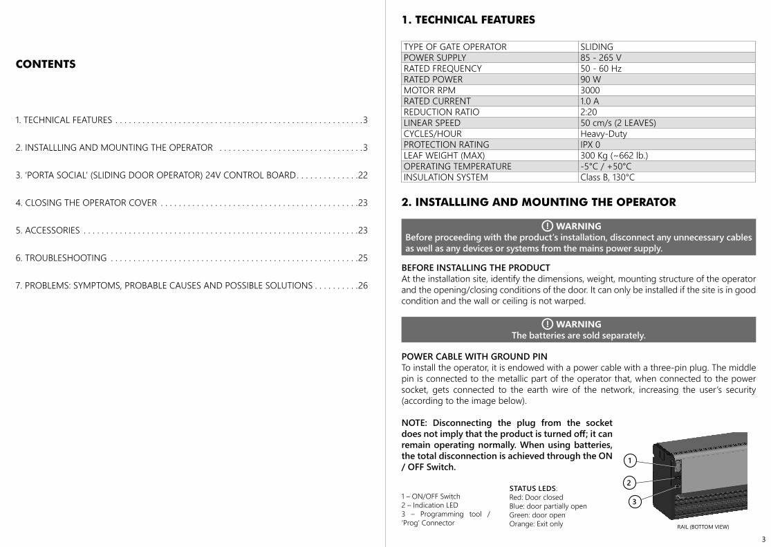
POWER CABLE WITH GROUND PINTo install the operator, it is endowed with a power cable with a three-pin plug. The middle pin is connected to the metallic part of the operator that, when connected to the power socket, gets connected to the earth wire of the network, increasing the user’s security (according to the image below).
NOTE: Disconnecting the plug from the socket does not imply that the product is turned off; it can remain operating normally. When using batteries, the total disconnection is achieved through the ON / OFF Switch.
1
2
3
RAIL (BOTTOM VIEW)
1 – ON/OFF Switch2 – Indication LED3 – Programming tool / ‘Prog’ Connector
STATUS LEDS:Red: Door closedBlue: door partially openGreen: door openOrange: Exit only
4 5
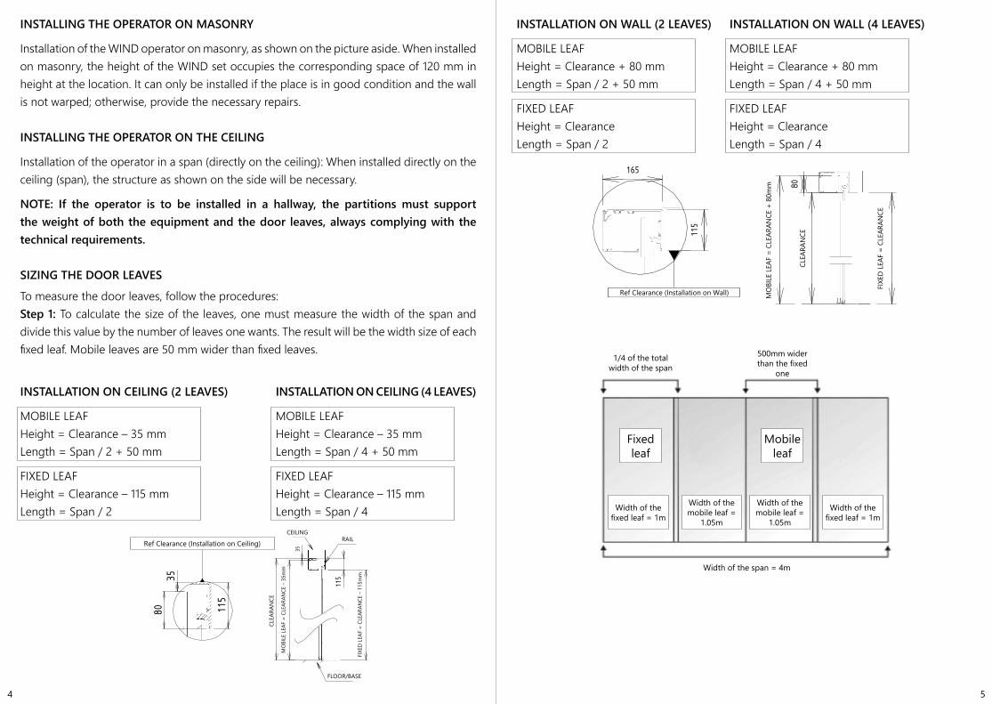
INSTALLING THE OPERATOR ON MASONRY
Installation of the WIND operator on masonry, as shown on the picture aside. When installed on masonry, the height of the WIND set occupies the corresponding space of 120 mm in height at the location. It can only be installed if the place is in good condition and the wall is not warped; otherwise, provide the necessary repairs.
INSTALLING THE OPERATOR ON THE CEILING
Installation of the operator in a span (directly on the ceiling): When installed directly on the ceiling (span), the structure as shown on the side will be necessary.
NOTE: If the operator is to be installed in a hallway, the partitions must support the weight of both the equipment and the door leaves, always complying with the technical requirements.
SIZING THE DOOR LEAVES
To measure the door leaves, follow the procedures:Step 1: To calculate the size of the leaves, one must measure the width of the span and divide this value by the number of leaves one wants. The result will be the width size of each fixed leaf. Mobile leaves are 50 mm wider than fixed leaves.
INSTALLATION ON CEILING (2 LEAVES) INSTALLATION ON CEILING (4 LEAVES)
MOBILE LEAF MOBILE LEAFHeight = Clearance – 35 mm Height = Clearance – 35 mmLength = Span / 2 + 50 mm Length = Span / 4 + 50 mm
FIXED LEAF FIXED LEAF Height = Clearance – 115 mm Height = Clearance – 115 mmLength = Span / 2 Length = Span / 4
3580 11
5
Ref. PD Instalaçao Teto
VIDR
O M
OVEL
= P
É DI
REIT
O -3
5mm
PISO/BASE
35
PÉ D
IREI
TO
VIDR
O FI
XO =
PÉ
DIRE
ITO
- 115
mm
TETOTRILHO
115
INSTALLATION ON WALL (2 LEAVES) INSTALLATION ON WALL (4 LEAVES)
MOBILE LEAF MOBILE LEAF Height = Clearance + 80 mm Height = Clearance + 80 mmLength = Span / 2 + 50 mm Length = Span / 4 + 50 mm
FIXED LEAF FIXED LEAFHeight = Clearance Height = ClearanceLength = Span / 2 Length = Span / 4
PÉ
DIR
EITO
VID
RO
MO
VEL
= P
É D
IR. +
80m
m 80
VID
RO
FIX
O =
PÉ
DIR
EITO
Ref. Pé Direito Inst. Parede
115
165
Ref Clearance (Installation on Ceiling)CEILING
CLEA
RAN
CE
MO
BILE
LEA
F =
CLEA
RAN
CE –
35m
m
FIXE
D L
EAF
= CL
EARA
NCE
– 1
15m
m
RAIL
FLOOR/BASE
Ref Clearance (Installation on Wall) MO
BILE
LEA
F =
CLEA
RAN
CE +
80m
m
CLEA
RAN
CE
FIXE
D L
EAF
= CL
EARA
NCE
1/4 of the total width of the span
500mm wider than the fixed
one
Fixed leaf
Mobile leaf
Width of the fixed leaf = 1m
Width of the fixed leaf = 1m
Width of the span = 4m
Width of the mobile leaf =
1.05m
Width of the mobile leaf =
1.05m
6 7
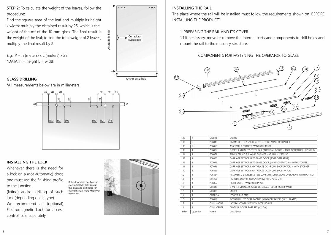
STEP 2: To calculate the weight of the leaves, follow the procedure:Find the square area of the leaf and multiply its height x width; multiply the obtained result by 25, which is theweight of the m² of the 10-mm glass. The final result is the weight of the leaf; to find the total weight of 2 leaves,multiply the final result by 2.
E.g.: P = h (meters) x L (meters) x 25*DATA: h = height L = width
GLASS DRILLING*All measurements below are in millimeters.
INSTALLING THE LOCKWhenever there is the need for a lock on a (not automatic) door, one must use the finishing profile to the junction(fitting) and/or drilling of such lock (depending on its type).We recommend an (optional) Electromagnetic Lock for access control, sold separately.
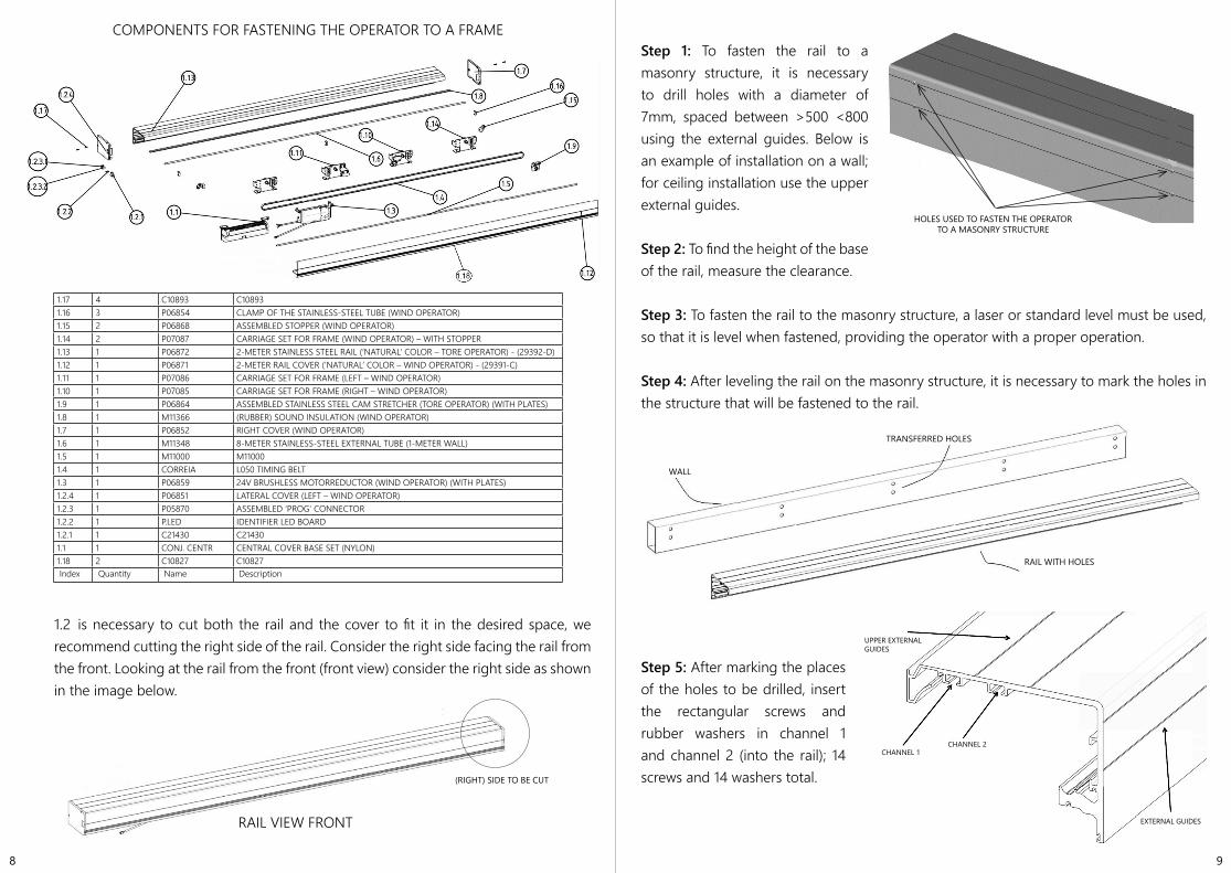
INSTALLING THE RAILThe place where the rail will be installed must follow the requirements shown on ‘BEFORE INSTALLING THE PRODUCT’.
1. PREPARING THE RAIL AND ITS COVER1.1 If necessary, move or remove the internal parts and components to drill holes and mount the rail to the masonry structure.
COMPONENTS FOR FASTENING THE OPERATOR TO GLASS
Altu
ra d
e la
hoj
a
Cerradura (Opcional)
Ancho de la hoja
If the door does not have an electronic lock, provide cut the glass and drill holes for fitting manual locks whenevernecessary.
1.18 4 C10893 C108931.17 3 P06845 CLAMP OF THE STAINLESS-STEEL TUBE (WIND OPERATOR)1.16 2 P06868 ASSEMBLED STOPPER (WIND OPERATOR)1.15 1 P06872 2-METER STAINLESS STEEL RAIL (‘NATURAL’ COLOR – TORE OPERATOR) - (29392-D)1.14 1 P06871 TAMPA TRILHO P.S. WIND 2,00 MTS NATURAL - (29391-C)1.13 1 P06866 CARRIAGE SET FOR LEFT GLASS DOOR (TORE OPERATOR)1.12 1 P07092 CARRIAGE SET FOR LEFT GLASS DOOR (WIND OPERATOR) – WITH STOPPER1.11 1 P07091 CARRIAGE SET FOR RIGHT GLASS DOOR (WIND OPERATOR) – WITH STOPPER1.10 1 P06865 CARRIAGE SET FOR RIGHT GLASS DOOR (WIND OPERATOR)1.9 1 P06864 ASSEMBLED STAINLESS STEEL CAM STRETCHER (TORE OPERATOR) (WITH PLATES)1.8 1 M11366 (RUBBER) SOUND INSULATION (WIND OPERATOR)1.7 1 P06852 RIGHT COVER (WIND OPERATOR)1.6 1 M11348 8-METER STAINLESS-STEEL EXTERNAL TUBE (1-METER WALL)1.5 1 M11000 M110001.4 1 CORREIA L050 TIMING BELT1.3 1 P06859 24V BRUSHLESS GEAR MOTOR (WIND OPERATOR) (WITH PLATES)1.2 1 CONJ. MONT. LATERAL COVER SET WITH ACCESSORIES1.1 1 CONJ. CENTR CENTRAL COVER BASE SET (NYLON)Index Quantity Name Description
8 9
COMPONENTS FOR FASTENING THE OPERATOR TO A FRAME
1.2 is necessary to cut both the rail and the cover to fit it in the desired space, we recommend cutting the right side of the rail. Consider the right side facing the rail from the front. Looking at the rail from the front (front view) consider the right side as shown in the image below.
RAIL VIEW FRONT
(RIGHT) SIDE TO BE CUT
Step 1: To fasten the rail to a masonry structure, it is necessary to drill holes with a diameter of 7mm, spaced between >500 <800 using the external guides. Below is an example of installation on a wall; for ceiling installation use the upper external guides.
Step 2: To find the height of the base of the rail, measure the clearance.
Step 3: To fasten the rail to the masonry structure, a laser or standard level must be used, so that it is level when fastened, providing the operator with a proper operation.
Step 4: After leveling the rail on the masonry structure, it is necessary to mark the holes in the structure that will be fastened to the rail.
Step 5: After marking the places of the holes to be drilled, insert the rectangular screws and rubber washers in channel 1 and channel 2 (into the rail); 14 screws and 14 washers total.
HOLES USED TO FASTEN THE OPERATOR TO A MASONRY STRUCTURE
TRANSFERRED HOLES
WALL
RAIL WITH HOLES
UPPER EXTERNAL GUIDES
CHANNEL 1CHANNEL 2
EXTERNAL GUIDES
1.17 4 C10893 C108931.16 3 P06854 CLAMP OF THE STAINLESS-STEEL TUBE (WIND OPERATOR)1.15 2 P06868 ASSEMBLED STOPPER (WIND OPERATOR)1.14 2 P07087 CARRIAGE SET FOR FRAME (WIND OPERATOR) – WITH STOPPER1.13 1 P06872 2-METER STAINLESS STEEL RAIL (‘NATURAL’ COLOR – TORE OPERATOR) - (29392-D)1.12 1 P06871 2-METER RAIL COVER (‘NATURAL’ COLOR – WIND OPERATOR) - (29391-C)1.11 1 P07086 CARRIAGE SET FOR FRAME (LEFT – WIND OPERATOR)1.10 1 P07085 CARRIAGE SET FOR FRAME (RIGHT – WIND OPERATOR)1.9 1 P06864 ASSEMBLED STAINLESS STEEL CAM STRETCHER (TORE OPERATOR) (WITH PLATES)1.8 1 M11366 (RUBBER) SOUND INSULATION (WIND OPERATOR)1.7 1 P06852 RIGHT COVER (WIND OPERATOR)1.6 1 M11348 8-METER STAINLESS-STEEL EXTERNAL TUBE (1-METER WALL)1.5 1 M11000 M110001.4 1 CORREIA L050 TIMING BELT1.3 1 P06859 24V BRUSHLESS MOTORREDUCTOR (WIND OPERATOR) (WITH PLATES)1.2.4 1 P06851 LATERAL COVER (LEFT – WIND OPERATOR)1.2.3 1 P05870 ASSEMBLED ‘PROG’ CONNECTOR1.2.2 1 P.LED IDENTIFIER LED BOARD1.2.1 1 C21430 C214301.1 1 CONJ. CENTR CENTRAL COVER BASE SET (NYLON)1.18 2 C10827 C10827Index Quantity Name Description
10 11
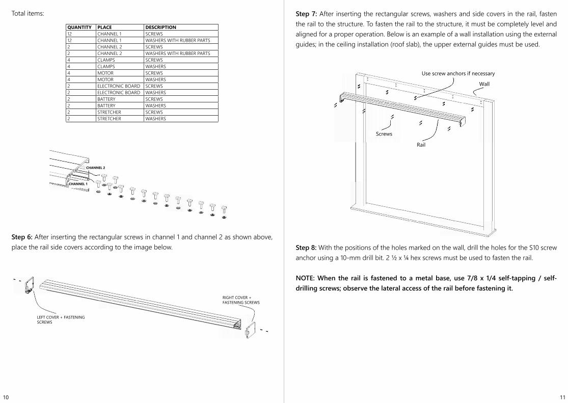
Total items:
Step 6: After inserting the rectangular screws in channel 1 and channel 2 as shown above, place the rail side covers according to the image below.
Step 7: After inserting the rectangular screws, washers and side covers in the rail, fasten the rail to the structure. To fasten the rail to the structure, it must be completely level and aligned for a proper operation. Below is an example of a wall installation using the external guides; in the ceiling installation (roof slab), the upper external guides must be used.
Step 8: With the positions of the holes marked on the wall, drill the holes for the S10 screw anchor using a 10-mm drill bit. 2 ½ x ¼ hex screws must be used to fasten the rail.
NOTE: When the rail is fastened to a metal base, use 7/8 x 1/4 self-tapping / self-drilling screws; observe the lateral access of the rail before fastening it.
CHANNEL 1
CHANNEL 2
LEFT COVER + FASTENING SCREWS
RIGHT COVER + FASTENING SCREWS
Use screw anchors if necessary
Wall
Screws
Rail
QUANTITY PLACE DESCRIPTION12 CHANNEL 1 SCREWS12 CHANNEL 1 WASHERS WITH RUBBER PARTS2 CHANNEL 2 SCREWS2 CHANNEL 2 WASHERS WITH RUBBER PARTS4 CLAMPS SCREWS4 CLAMPS WASHERS4 MOTOR SCREWS4 MOTOR WASHERS2 ELECTRONIC BOARD SCREWS2 ELECTRONIC BOARD WASHERS2 BATTERY SCREWS2 BATTERY WASHERS2 STRETCHER SCREWS2 STRETCHER WASHERS
12 13
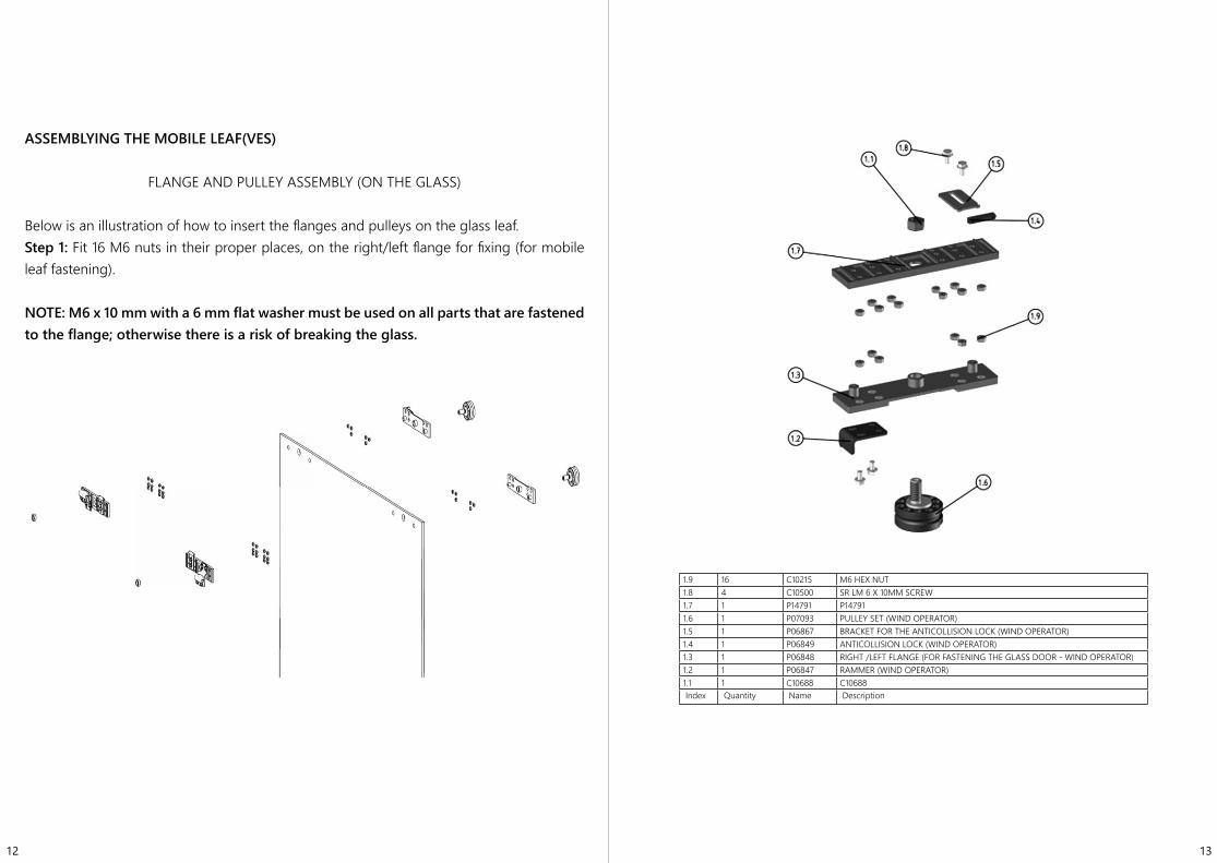
ASSEMBLYING THE MOBILE LEAF(VES)
FLANGE AND PULLEY ASSEMBLY (ON THE GLASS)
Below is an illustration of how to insert the flanges and pulleys on the glass leaf.Step 1: Fit 16 M6 nuts in their proper places, on the right/left flange for fixing (for mobile leaf fastening).
NOTE: M6 x 10 mm with a 6 mm flat washer must be used on all parts that are fastened to the flange; otherwise there is a risk of breaking the glass.
1.9 16 C10215 M6 HEX NUT1.8 4 C10500 SR LM 6 X 10MM SCREW1.7 1 P14791 P147911.6 1 P07093 PULLEY SET (WIND OPERATOR)1.5 1 P06867 BRACKET FOR THE ANTICOLLISION LOCK (WIND OPERATOR)1.4 1 P06849 ANTICOLLISION LOCK (WIND OPERATOR)1.3 1 P06848 RIGHT /LEFT FLANGE (FOR FASTENING THE GLASS DOOR - WIND OPERATOR)1.2 1 P06847 RAMMER (WIND OPERATOR)1.1 1 C10688 C10688Index Quantity Name Description
14 15
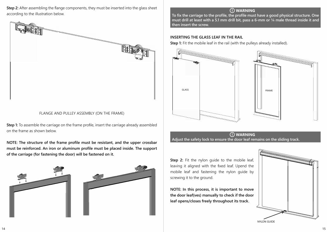
Step 2: After assembling the flange components, they must be inserted into the glass sheet according to the illustration below.
FLANGE AND PULLEY ASSEMBLY (ON THE FRAME)
Step 1: To assemble the carriage on the frame profile, insert the carriage already assembled on the frame as shown below.
NOTE: The structure of the frame profile must be resistant, and the upper crossbar must be reinforced. An iron or aluminum profile must be placed inside. The support of the carriage (for fastening the door) will be fastened on it.
WARNINGTo fix the carriage to the profile, the profile must have a good physical structure. One must drill at least with a 5.1 mm drill bit, pass a 6-mm or ¼ male thread inside it and then insert the screw.
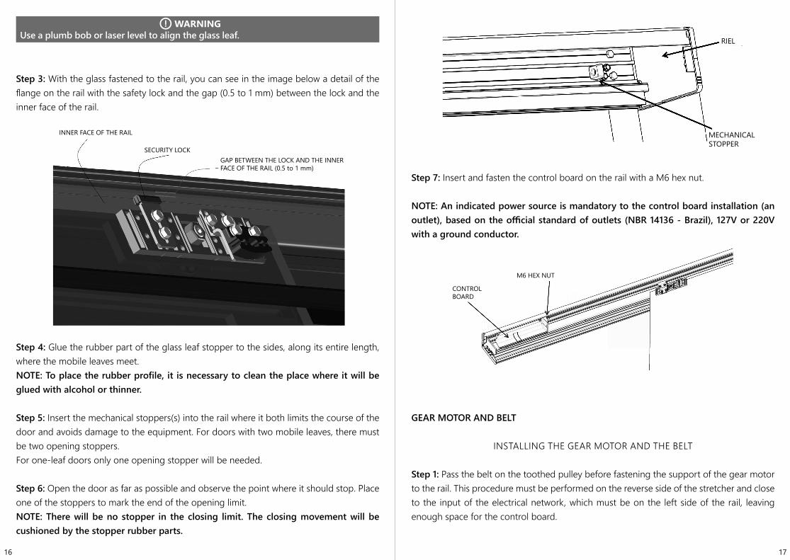
INSERTING THE GLASS LEAF IN THE RAILStep 1: Fit the mobile leaf in the rail (with the pulleys already installed).
WARNINGAdjust the safety lock to ensure the door leaf remains on the sliding track.
Step 2: Fit the nylon guide to the mobile leaf, leaving it aligned with the fixed leaf. Upend the mobile leaf and fastening the nylon guide by screwing it to the ground.
NOTE: In this process, it is important to move the door leaf(ves) manually to check if the door leaf opens/closes freely throughout its track.
GLASS FRAME
NYLON GUIDE
16 17
WARNINGUse a plumb bob or laser level to align the glass leaf.
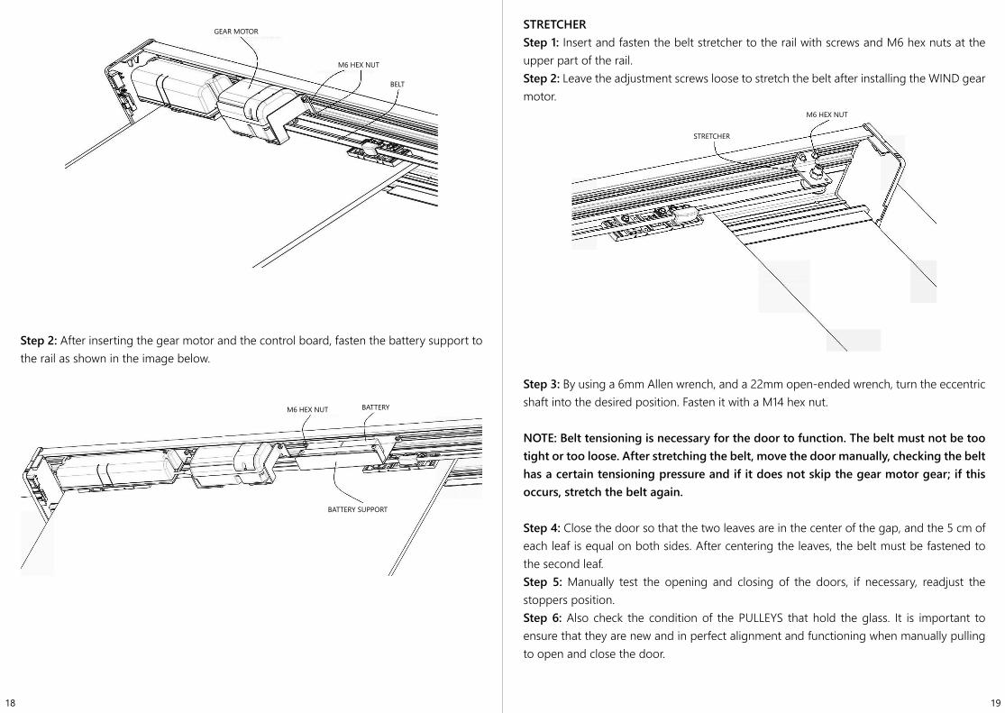
Step 3: With the glass fastened to the rail, you can see in the image below a detail of the flange on the rail with the safety lock and the gap (0.5 to 1 mm) between the lock and the inner face of the rail.
Step 4: Glue the rubber part of the glass leaf stopper to the sides, along its entire length, where the mobile leaves meet.NOTE: To place the rubber profile, it is necessary to clean the place where it will be glued with alcohol or thinner.
Step 5: Insert the mechanical stoppers(s) into the rail where it both limits the course of the door and avoids damage to the equipment. For doors with two mobile leaves, there must be two opening stoppers.For one-leaf doors only one opening stopper will be needed.
Step 6: Open the door as far as possible and observe the point where it should stop. Place one of the stoppers to mark the end of the opening limit.NOTE: There will be no stopper in the closing limit. The closing movement will be cushioned by the stopper rubber parts.
Step 7: Insert and fasten the control board on the rail with a M6 hex nut.
NOTE: An indicated power source is mandatory to the control board installation (an outlet), based on the official standard of outlets (NBR 14136 - Brazil), 127V or 220V with a ground conductor.
GEAR MOTOR AND BELT
INSTALLING THE GEAR MOTOR AND THE BELT
Step 1: Pass the belt on the toothed pulley before fastening the support of the gear motor to the rail. This procedure must be performed on the reverse side of the stretcher and close to the input of the electrical network, which must be on the left side of the rail, leaving enough space for the control board.
INNER FACE OF THE RAIL
SECURITY LOCKGAP BETWEEN THE LOCK AND THE INNER FACE OF THE RAIL (0.5 to 1 mm)
RIEL
MECHANICAL STOPPER
CONTROL BOARD
M6 HEX NUT
18 19
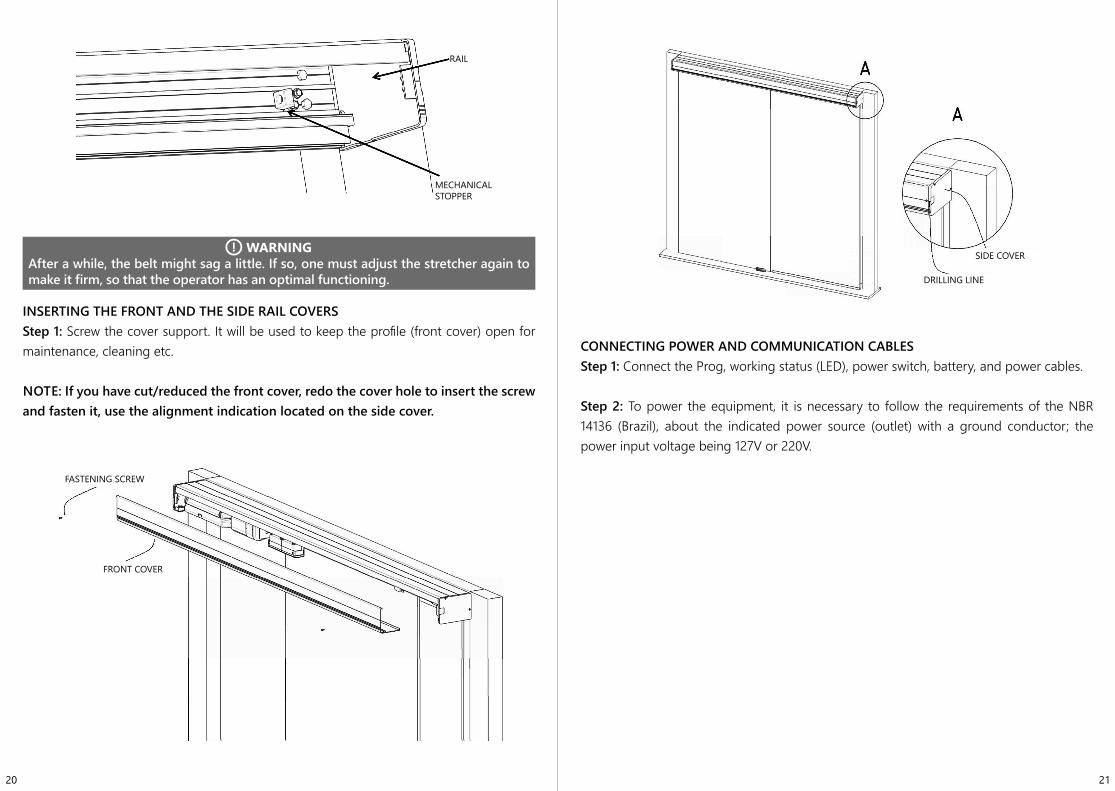
Step 2: After inserting the gear motor and the control board, fasten the battery support to the rail as shown in the image below.
STRETCHERStep 1: Insert and fasten the belt stretcher to the rail with screws and M6 hex nuts at the upper part of the rail.Step 2: Leave the adjustment screws loose to stretch the belt after installing the WIND gear motor.
Step 3: By using a 6mm Allen wrench, and a 22mm open-ended wrench, turn the eccentric shaft into the desired position. Fasten it with a M14 hex nut.
NOTE: Belt tensioning is necessary for the door to function. The belt must not be too tight or too loose. After stretching the belt, move the door manually, checking the belt has a certain tensioning pressure and if it does not skip the gear motor gear; if this occurs, stretch the belt again.
Step 4: Close the door so that the two leaves are in the center of the gap, and the 5 cm of each leaf is equal on both sides. After centering the leaves, the belt must be fastened to the second leaf.Step 5: Manually test the opening and closing of the doors, if necessary, readjust the stoppers position.Step 6: Also check the condition of the PULLEYS that hold the glass. It is important to ensure that they are new and in perfect alignment and functioning when manually pulling to open and close the door.
GEAR MOTOR
M6 HEX NUT
BELT
M6 HEX NUT BATTERY
BATTERY SUPPORT
STRETCHER
M6 HEX NUT
20 21
WARNINGAfter a while, the belt might sag a little. If so, one must adjust the stretcher again to make it firm, so that the operator has an optimal functioning.
INSERTING THE FRONT AND THE SIDE RAIL COVERSStep 1: Screw the cover support. It will be used to keep the profile (front cover) open for maintenance, cleaning etc.
NOTE: If you have cut/reduced the front cover, redo the cover hole to insert the screw and fasten it, use the alignment indication located on the side cover.
CONNECTING POWER AND COMMUNICATION CABLESStep 1: Connect the Prog, working status (LED), power switch, battery, and power cables.
Step 2: To power the equipment, it is necessary to follow the requirements of the NBR 14136 (Brazil), about the indicated power source (outlet) with a ground conductor; the power input voltage being 127V or 220V.
RAIL
MECHANICAL STOPPER
FASTENING SCREW
FRONT COVER
SIDE COVER
DRILLING LINE
22 23
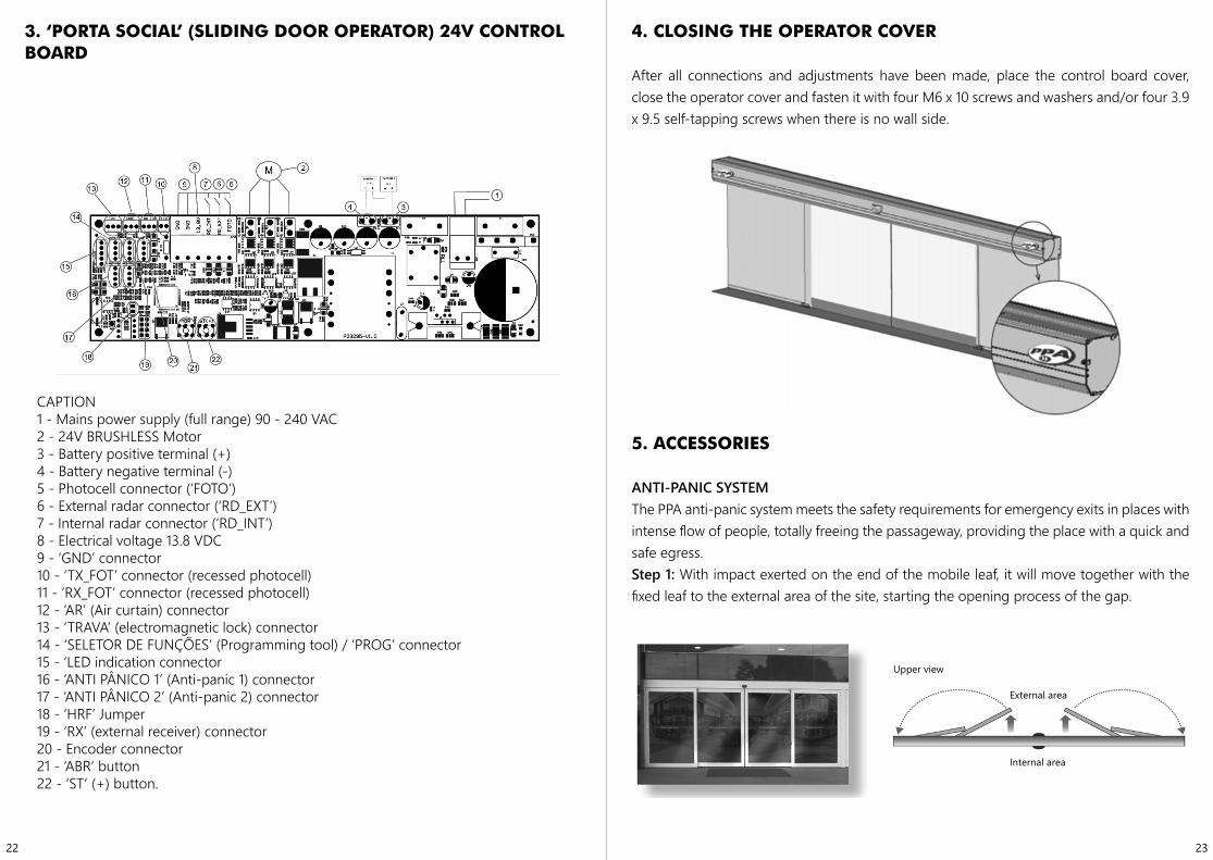
3. ‘PORTA SOCIAL’ (SLIDING DOOR OPERATOR) 24V CONTROL BOARD
LEGENDA1 - Alimentação rede elétrica (full range) 90 - 240 VAC;2 - Motor BRUSHLESS 24 V;3 - Terminal positivo da bateria (+);4 - Terminal negativo da bateria (-);5 - Conector fotocélula (FOTO);6 - Conector radar externo (RD_EXT);7 - Conector radar externo (RD_INT);8 - Tensão elétrica 13,8 V;9 - Conector GND;10 - Conector TX_FOT (fotocélula embutir);11 - Conector RX_FOT (fotocélula embutir);12 - Conector cortina de AR;13 - Conector TRAVA;14 - Conector SELETOR DE FUNÇÕES / PROG;15 - Conector sinalização LEDs;16 - Conector ANTI PÂNICO 1;17 - Conector ANTI PÂNICO 2;18 - Jumper HRF;19 - Conector RX (receptor externo);20 - Conector Encoder;21 - Botão ABR;22 - Botão ST (+).
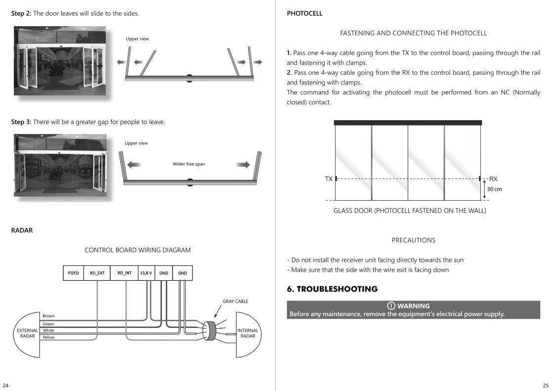
4. CLOSING THE OPERATOR COVER
After all connections and adjustments have been made, place the control board cover, close the operator cover and fasten it with four M6 x 10 screws and washers and/or four 3.9 x 9.5 self-tapping screws when there is no wall side.
5. ACCESSORIES
ANTI-PANIC SYSTEMThe PPA anti-panic system meets the safety requirements for emergency exits in places with intense flow of people, totally freeing the passageway, providing the place with a quick and safe egress.Step 1: With impact exerted on the end of the mobile leaf, it will move together with the fixed leaf to the external area of the site, starting the opening process of the gap.
CAPTION1 - Mains power supply (full range) 90 - 240 VAC2 - 24V BRUSHLESS Motor3 - Battery positive terminal (+)4 - Battery negative terminal (-)5 - Photocell connector (‘FOTO’)6 - External radar connector (‘RD_EXT’)7 - Internal radar connector (‘RD_INT’)8 - Electrical voltage 13.8 VDC9 - ‘GND’ connector10 - ‘TX_FOT’ connector (recessed photocell)11 - ‘RX_FOT’ connector (recessed photocell)12 - ‘AR’ (Air curtain) connector13 - ‘TRAVA’ (electromagnetic lock) connector14 - ‘SELETOR DE FUNÇÕES’ (Programming tool) / ‘PROG’ connector15 - ‘LED indication connector16 - ‘ANTI PÂNICO 1’ (Anti-panic 1) connector17 - ‘ANTI PÂNICO 2’ (Anti-panic 2) connector18 - ‘HRF’ Jumper19 - ‘RX’ (external receiver) connector20 - Encoder connector21 - ‘ABR’ button22 - ‘ST’ (+) button.
Upper view
External area
Internal area
24 25
Step 2: The door leaves will slide to the sides.
Step 3: There will be a greater gap for people to leave.
RADAR
CONTROL BOARD WIRING DIAGRAM
EXTERNAL RADAR
INTERNAL RADAR
GRAY CABLE
PHOTOCELL
FASTENING AND CONNECTING THE PHOTOCELL
1. Pass one 4-way cable going from the TX to the control board, passing through the rail and fastening it with clamps.2. Pass one 4-way cable going from the RX to the control board, passing through the rail and fastening with clamps.The command for activating the photocell must be performed from an NC (Normally closed) contact.
GLASS DOOR (PHOTOCELL FASTENED ON THE WALL)
PRECAUTIONS
- Do not install the receiver unit facing directly towards the sun- Make sure that the side with the wire exit is facing down
6. TROUBLESHOOTING
WARNINGBefore any maintenance, remove the equipment’s electrical power supply.
Upper view
Upper view
Wider free span
Brown
GreenWhiteYellow

26
7. PROBLEMS: SYMPTOMS, PROBABLE CAUSES AND POSSIBLE SOLUTIONS
The table below contains useful information on some PROBLEMS — SYMPTOMS, PROBABLE CAUSES AND POSSIBLE SOLUTIONS which might affect your operator.
SYMPTOMS PROBABLE CAUSE(S) ACTION(S)
Door opening / closing by itself.
- Dirt on the rail.- Dirt on the door guide.- Radar poorly adjusted,
detecting the door’s moviment.
- Clean the rail.- Clean the door guides.
- Adjust the radar sensitivity
Door opening slowly. - Lack of electric energy.- Activate the radar and
wait for the door to open and close slowly.
Door has opened but has not closed - Photocell obstruction. - Clear the photocell.