Puntos claves del FC
56
Hydraulic Fracture Hydraulic Fracturing Hydraulic Fracturing Short Course, Short Course, Texas A&M University Texas A&M University College Station College Station 2005 2005 Modeling, Monitoring, Post- Job Evaluation, Improvements
-
Upload
miguel-vidal-arango -
Category
Documents
-
view
18 -
download
0
description
Curso resumen de fracturamiento hidraulico
Transcript of Puntos claves del FC
Hydraulic Fracture
Hydraulic FracturingHydraulic FracturingShort Course, Short Course,
Texas A&M UniversityTexas A&M UniversityCollege StationCollege Station
20052005
Modeling, Monitoring, Post-Job Evaluation, Improvements
FractureModeling+
2
3D3D
FractureModeling+
3
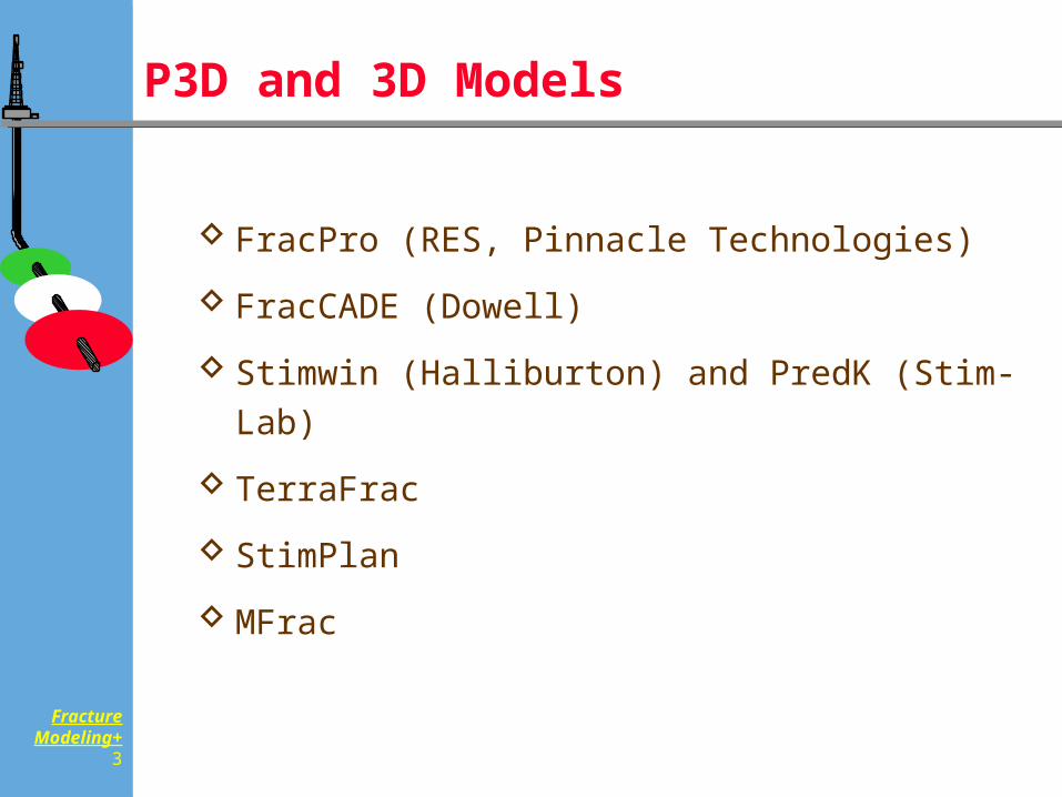
P3D and 3D Models
FracPro (RES, Pinnacle Technologies)
FracCADE (Dowell)
Stimwin (Halliburton) and PredK (Stim-Lab)
TerraFrac
StimPlan
MFrac
FractureModeling+
4
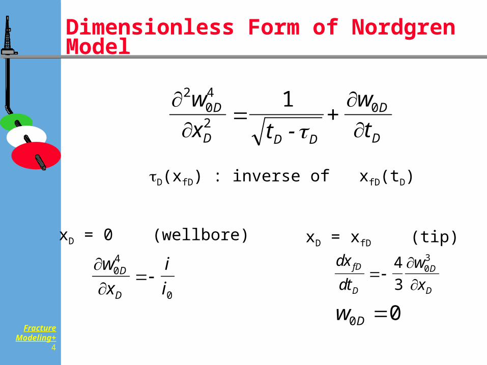
Dimensionless Form of Nordgren Model
204
201w
x t -+
wt
D
D D D
D
D
wx
ii
D
D
04
0
dxdt
wx
fD
D
D
D
43
03
xD = 0 (wellbore) xD = xfD (tip)
D(xfD) : inverse of xfD(tD)
w D0 0
FractureModeling+
5
Propagation Criterion of the Nordgren Model
Net pressure zero at tip
Once the fluid reaches the location, it opens up immediately
Propagation rate is determined by “how fast the fluid can flow
FractureModeling+
6
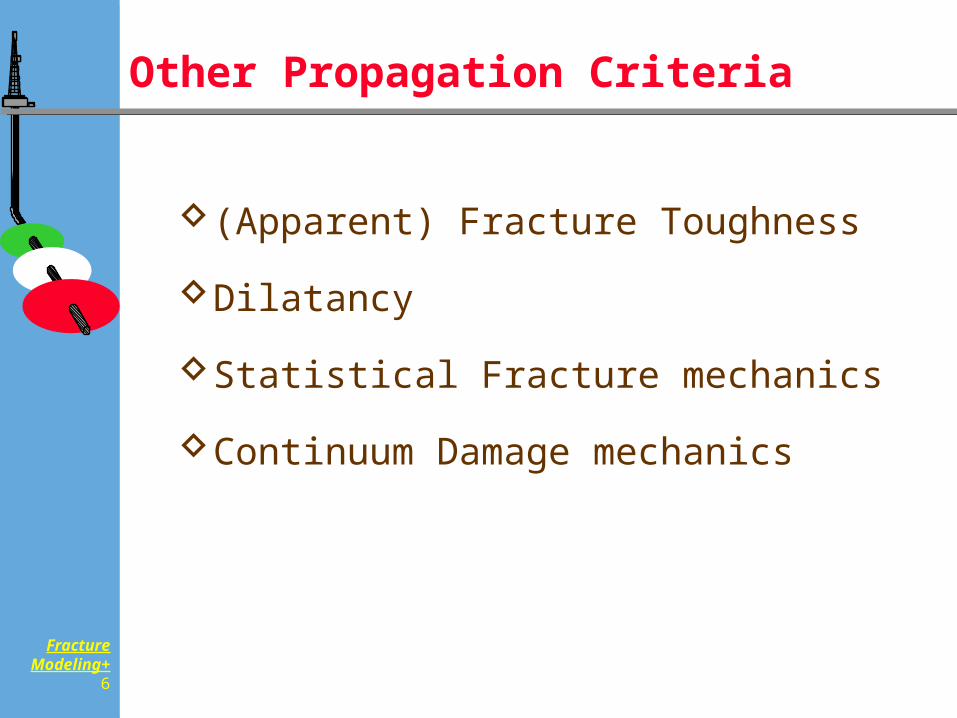
Other Propagation Criteria
(Apparent) Fracture Toughness
Dilatancy
Statistical Fracture mechanics
Continuum Damage mechanics
FractureModeling+
7
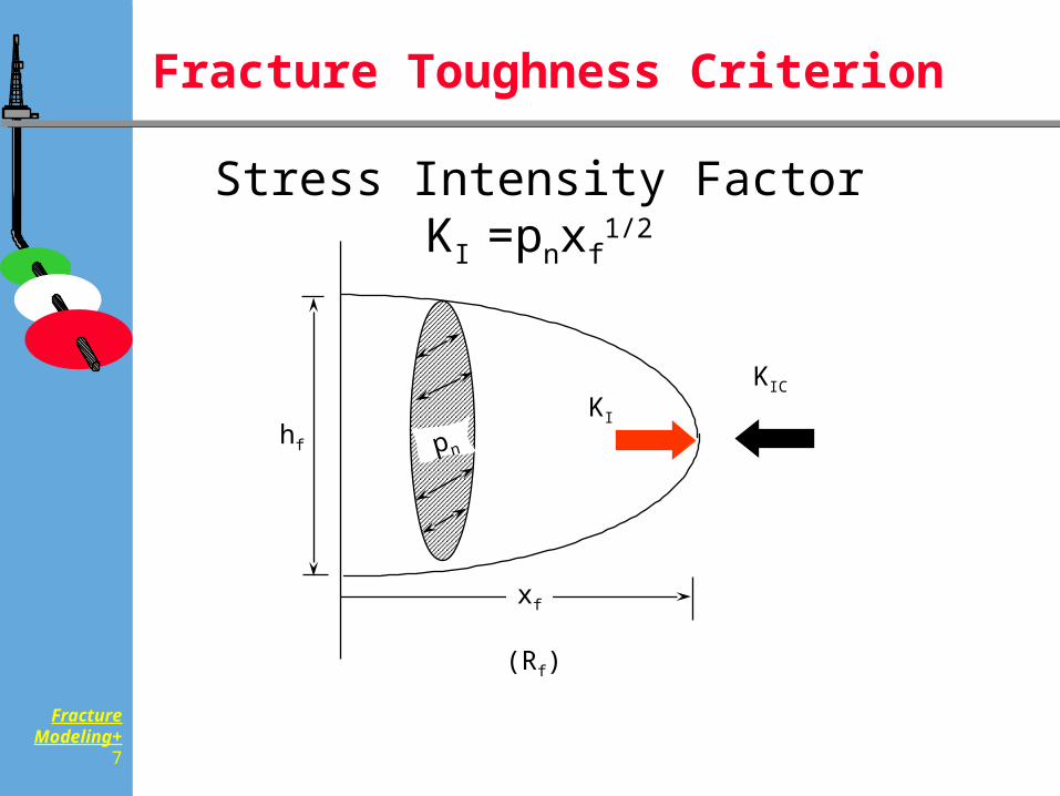
Fracture Toughness Criterion
KI
xf
hf pn
KIC
(Rf)
Stress Intensity Factor KI =pnxf1/2
FractureModeling+
8
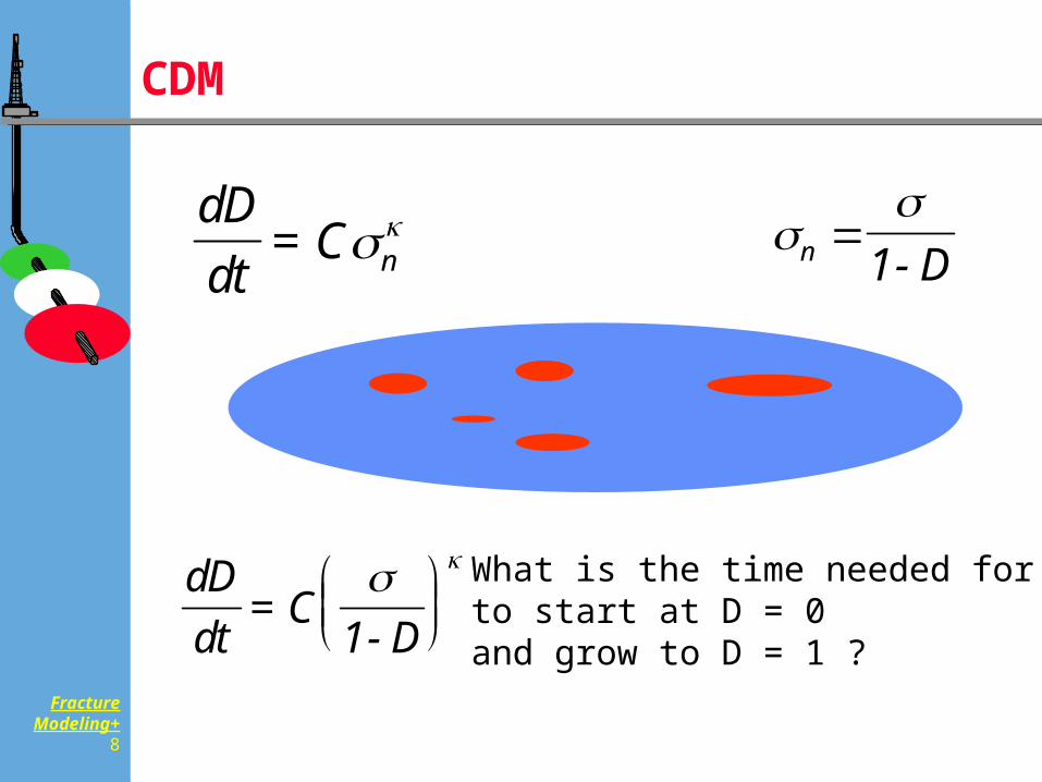
CDM
dDdt
= C n
n 1- D
dDdt
= C1- D
What is the time needed for D to start at D = 0 and grow to D = 1 ?
FractureModeling+
9
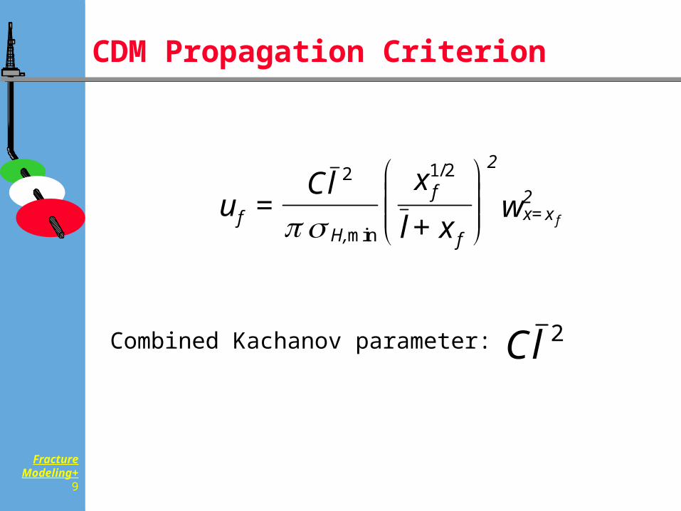
CDM Propagation Criterion
u =Cl x
l + xwf
H,
2
f
fx=x2
f
2 1 2
min
/
Cl 2Combined Kachanov parameter:
FractureModeling+
10
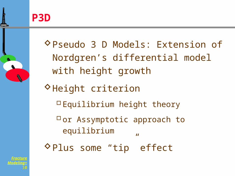
P3D
Pseudo 3 D Models: Extension of Nordgren’s differential model with height growth
Height criterionEquilibrium height theory
or Assymptotic approach to equilibrium
Plus some “tip” effect
FractureModeling+
11
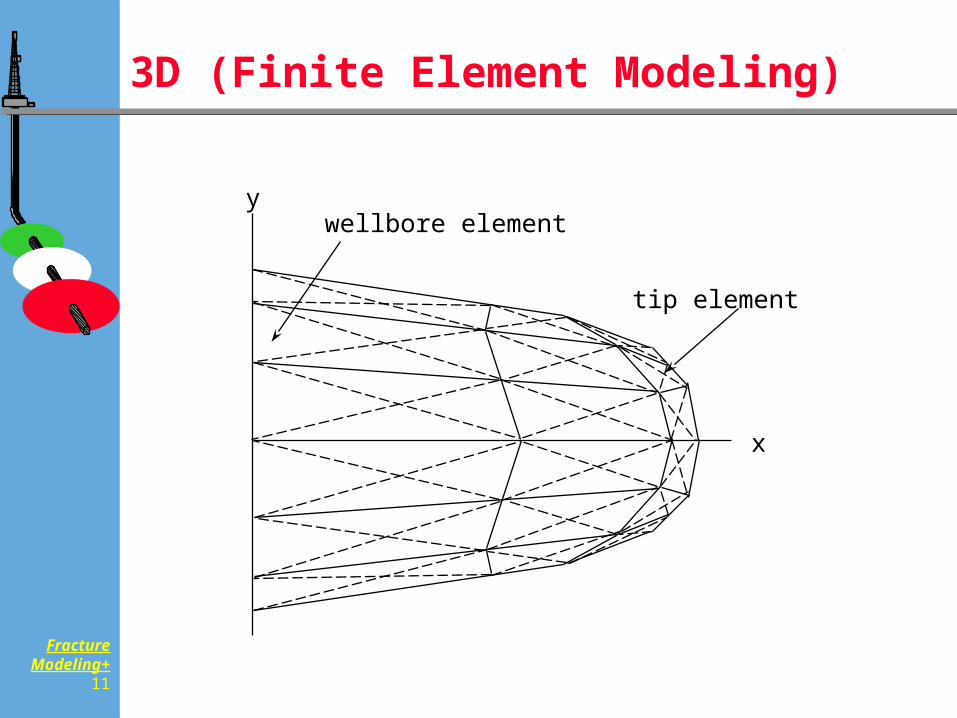
3D (Finite Element Modeling)
x
ywellbore element
tip element
FractureModeling+
12
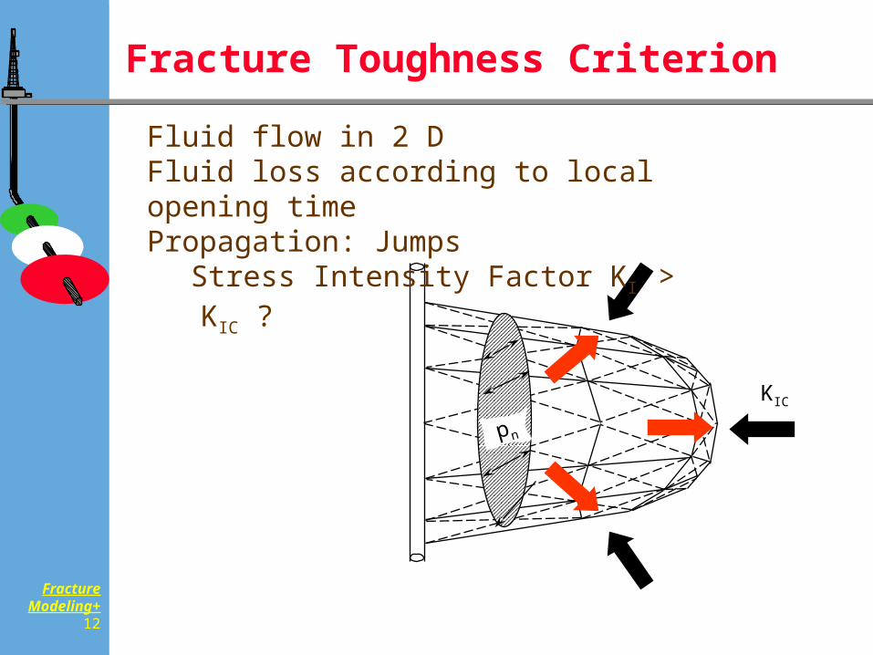
Fracture Toughness Criterion
pn
KIC
Fluid flow in 2 DFluid loss according to local opening timePropagation: Jumps
Stress Intensity Factor KI > KIC ?
FractureModeling+
13
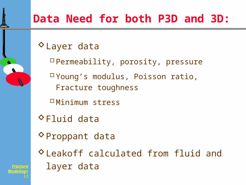
Data Need for both P3D and 3D:
Layer dataPermeability, porosity, pressure
Young’s modulus, Poisson ratio, Fracture toughness
Minimum stress
Fluid data
Proppant data
Leakoff calculated from fluid and layer data
FractureModeling+
14
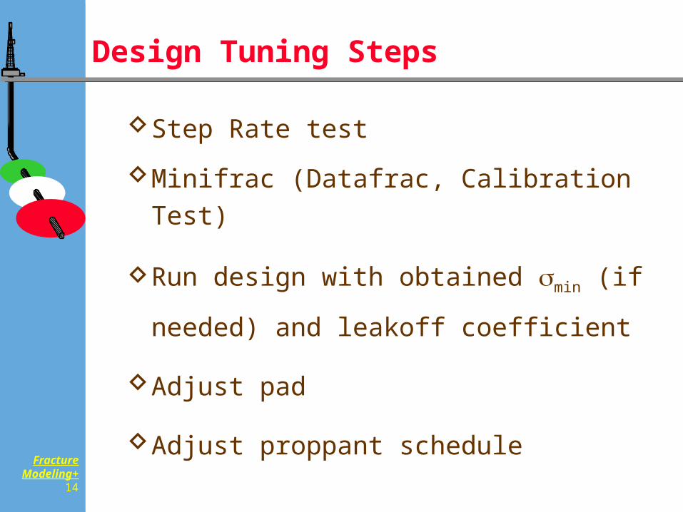
Design Tuning Steps
Step Rate test
Minifrac (Datafrac, Calibration Test)
Run design with obtained min (if needed)
and leakoff coefficient
Adjust pad
Adjust proppant schedule
FractureModeling+
15
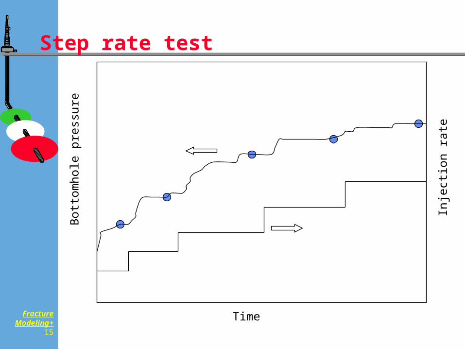
Step rate test
Time
Bot
tom
hole
pre
ssur
e
Inje
ctio
n ra
te
FractureModeling+
16
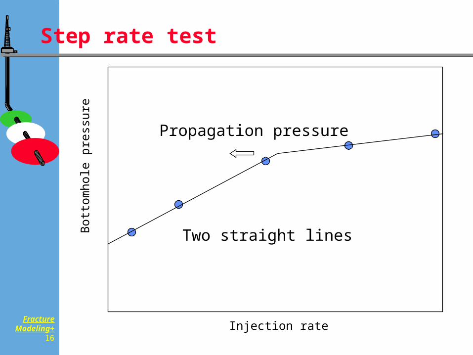
Step rate test
Injection rate
Bot
tom
hole
pre
ssur
e
Propagation pressure
Two straight lines
FractureModeling+
17
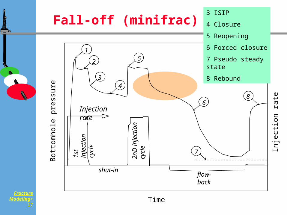
Fall-off (minifrac)
1st
injec
tion
cycle
2nD
injec
tion
cycle
flow-backshut-in
1
2
34
5
68
7
Injection rate
Time
Bot
tom
hole
pre
ssur
e
Inje
ctio
n ra
te
3 ISIP
4 Closure
5 Reopening
6 Forced closure
7 Pseudo steady state
8 Rebound
FractureModeling+
18
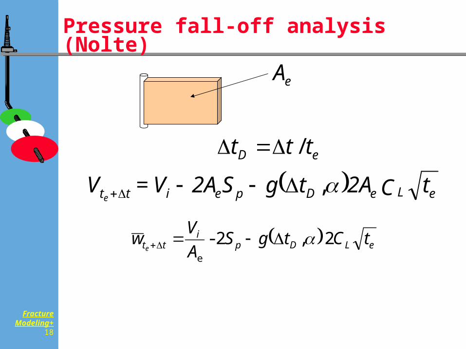
Pressure fall-off analysis(Nolte)
eLeDpeitt tC2AtgS2AV=Ve
,
eD ttt /
eLDpi
tt tCtgSAVw
e2 ,2-
e
eA
FractureModeling+
19
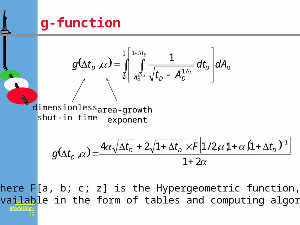
g-function
where F[a, b; c; z] is the Hypergeometric function, available in the form of tables and computing algorithms
dimensionless shut-in time
area-growth exponent
D
t
AD
DD
D dAdtAt
tgD
D
1
0
1
/1/1
1,
211;1;,2/1124
,1
DDDD
tFtttg
FractureModeling+
20
g-function
FractureModeling+
21
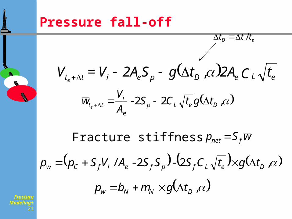
Pressure fall-off
,2-2-/ DeLfpfeifCw tgtCSSSAVSpp
p b m g tw N N D ,
eLeDpeitt tC2AtgS2AV=Ve
,
eD ttt /
,22- e
DeLpi
tt tgtCSAVw
e
wSp fnet Fracture stiffness
FractureModeling+
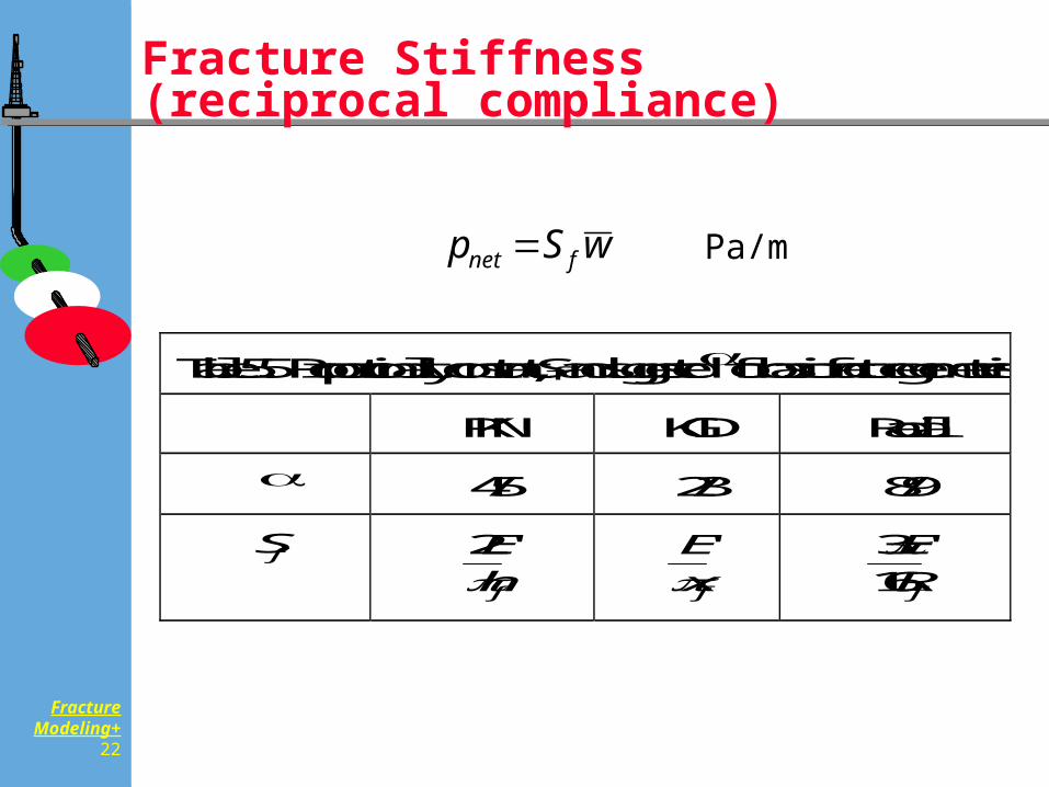
22
Fracture Stiffness(reciprocal compliance)
Table 5.5 Proportionality constant, Sf and suggested for basic fracture geometries
PKN KGD Radial
4/5 2/3 8/9
Sf 2Ehf
'
Exf
'
316ERf
'
wSp fnet Pa/m
FractureModeling+
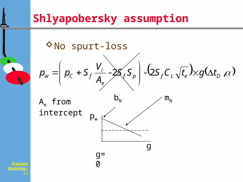
23
Shlyapobersky assumption
No spurt-loss
,2-2- DeLfpfe
ifCw tgtCSSS
AVSpp
Ae from intercept
g
pw
bN mN
g=0
FractureModeling+
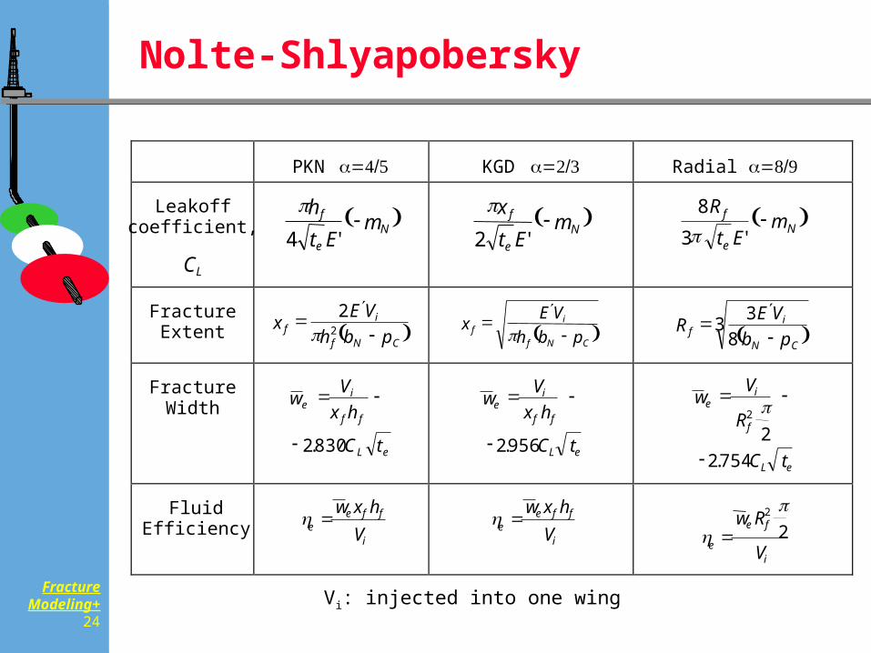
24
Nolte-Shlyapobersky
PKN KGD Radial
Leakoffcoefficient,
CL
Ne
f mEt
h
'4
Ne
f mEt
x
'2
Ne
f mEt
R
'3
8
FractureExtent CNf
if pbh
VEx
22
CNf
if pbh
VEx
3
83
CN
if pb
VER
FractureWidth
eL
ff
ie
tC
hxV
w
830.2
eL
ff
ie
tC
hxV
w
956.2
eL
f
ie
tC
R
Vw
754.22
2
FluidEfficiency
i
ffee V
hxw
i
ffee V
hxw
i
fe
e V
Rw2
2
Vi: injected into one wing
FractureModeling+
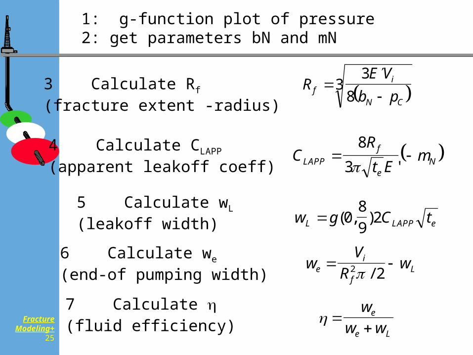
25
7 Calculate
(fluid efficiency)
3 Calculate Rf
(fracture extent -radius)
4 Calculate CLAPP
(apparent leakoff coeff)
5 Calculate wL
(leakoff width)
6 Calculate we
(end-of pumping width)
RE V
b pfi
N C
38
3
CRt E
mLAPPf
eN
83 '
w g C tL LAPP e ( , )089
2
wV
Rwe
i
fL 2 2 /
w
w we
e L
1: g-function plot of pressure2: get parameters bN and mN
FractureModeling+
26
Computer Exercise 3-1 Minifrac analysis
FractureModeling+
27
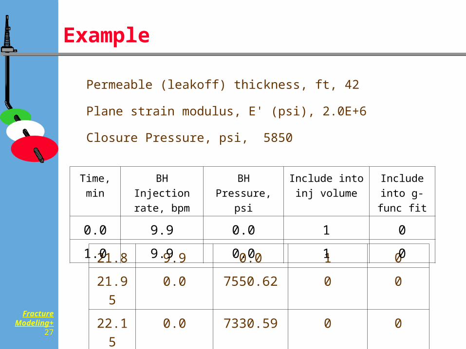
Example
Permeable (leakoff) thickness, ft, 42
Plane strain modulus, E' (psi), 2.0E+6
Closure Pressure, psi, 5850
21.8 9.9 0.0 1 0
21.95 0.0 7550.62 0 0
22.15 0.0 7330.59 0 0
Time, min
BH Injection rate, bpm
BH Pressure, psi
Include into inj volume
Include into g-func fit
0.0 9.9 0.0 1 0
1.0 9.9 0.0 1 0
FractureModeling+
28
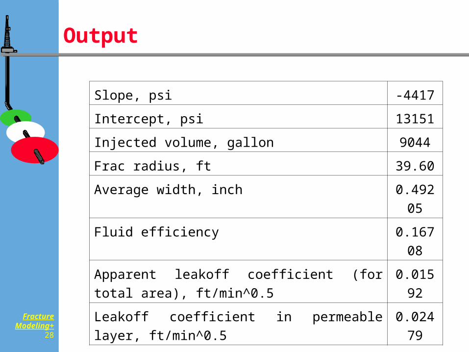
Output
Slope, psi -4417
Intercept, psi 13151
Injected volume, gallon 9044
Frac radius, ft 39.60
Average width, inch 0.49205
Fluid efficiency 0.16708
Apparent leakoff coefficient (for total area), ft/min^0.5
0.01592
Leakoff coefficient in permeable layer, ft/min^0.5 0.02479
FractureModeling+
29
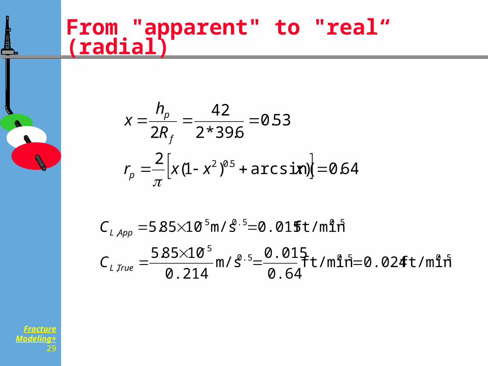
From "apparent" to "real“ (radial)
64.0)arcsin()1(2
53.06.39*2
422
5.02
xxxr
Rh
x
p
f
p
ft/min 0.024 ft/min 0.640.015 m/s
0.2141085.5
ft/min 0.015 m/s1085.5
0.50.50.55
,
0.50.55,
TrueL
AppL
C
C
FractureModeling+
30
Redesign
Run the design with new leakoff
coefficient
(That is why we do minifrac analysis)
FractureModeling+
31
Monitoring
Calculate proppant concentration at bottom (shift)
Calculate bottomhole injection pressure, net pressure
Calculate proppant in formation, proppant in well
Later: Add and synchronize gauge pressure
FractureModeling+
32
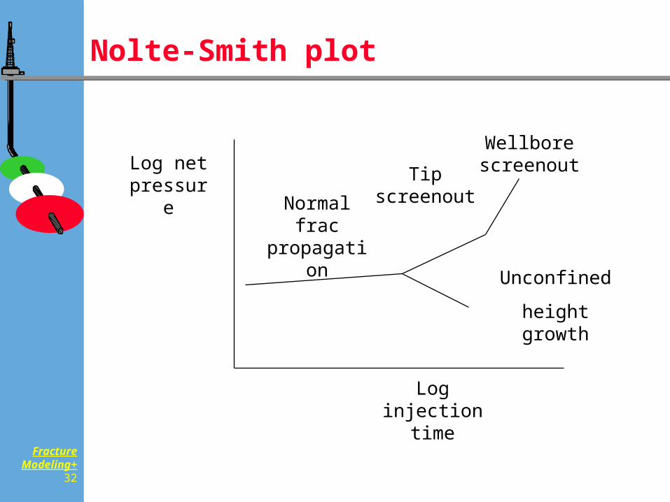
Nolte-Smith plot
Log net pressure
Log injection time
Normal frac propagation
Tip screenout
Wellbore screenout
Unconfined
height growth
FractureModeling+
33
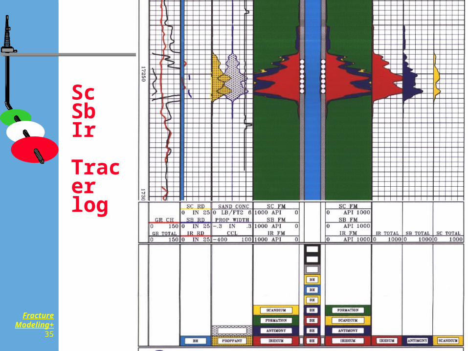
Post-Job Logging
Tracer Log
Temperature Log
Production Log

FractureModeling+
34
Radius of penetration
Available Techniques for Width and Height
Measured Directly Formation Micro Scanner Borehole Televiewer
Based on Inference Temperature Logging Isotopes (fluid, proppant) Seismic Methods, Noise Logging Tiltmeter techniques Spinner survey
FractureModeling+
35
ScSb Ir
Tracerlog
FractureModeling+
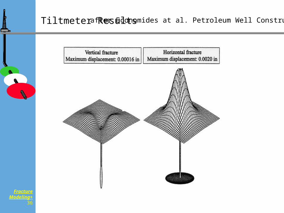
36
Tiltmeter Results after Economides at al. Petroleum Well Construction
FractureModeling+
37
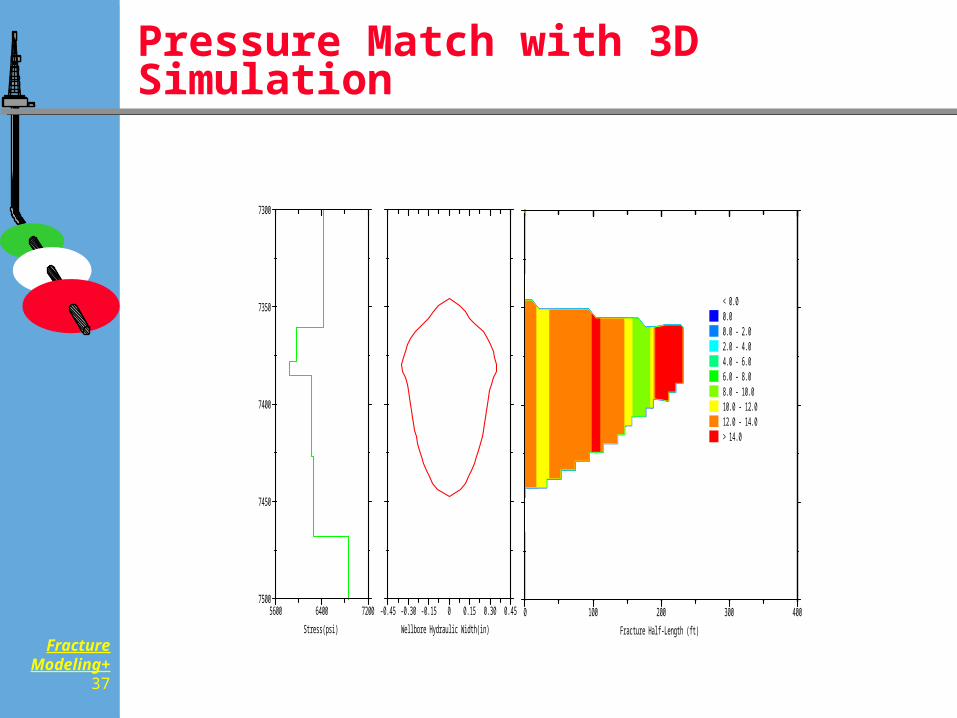
0 100 200 300 400
Fracture Half-Length (ft)
< 0.00.00.0 - 2.02.0 - 4.04.0 - 6.06.0 - 8.08.0 - 10.010.0 - 12.012.0 - 14.0> 14.0
FracCADE
*Mark of Schlumberger
EOJ Fracture Profile and Proppant Concentration
Texaco E&POCS-G 10752 #D-12Actual05-23-1997
-0.45 -0.30 -0.15 0 0.15 0.30 0.45
Wellbore Hydraulic Width(in)
5600 6400 7200
Stress(psi)
7300
7350
7400
7450
7500
Pressure Match with 3D Simulation
FractureModeling+
38
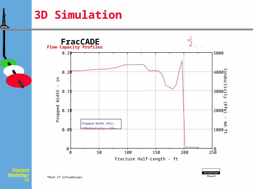
3D Simulation
0 50 100 150 200 250Fracture Half-Length - ft
0
0.05
0.10
0.15
0.20
0.25P
ropp
ed W
idth
- in
0
1000
2000
3000
4000
5000
Conductivity (K
fw) - m
d.ftPropped Width (ACL)
Conductivity - Kfw
FracCADE
*Mark of Schlumberger
Flow Capacity Profiles
Texaco E&POCS-G 10752 #D-12
Actual05-23-1997
FractureModeling+
39
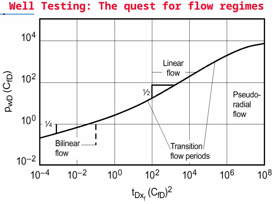
Well Testing: The quest for flow regimes
FractureModeling+
40
Design Improvement in a Field Program
Sizing Pad volume for “generic” design More aggressive or defensive proppant
schedule Proppant change (resin coated, high strength
etc.) Fluid system modification (crosslinked, foam)
Proppant carrying capacity Leakoff
Perforation strategy changes Forced closure, Resin coating, Fiber
reinforcement, Deformable particle
FractureModeling+
41
Example: Tortuous Flow Path
Analysis of the injection rate dependent element of the treating pressure
Does proppant slug help?
Does limited entry help?
Does oriented perforation help?
Extreme: reconsidering well orientation:
e.g. S shaped
FractureModeling+
42
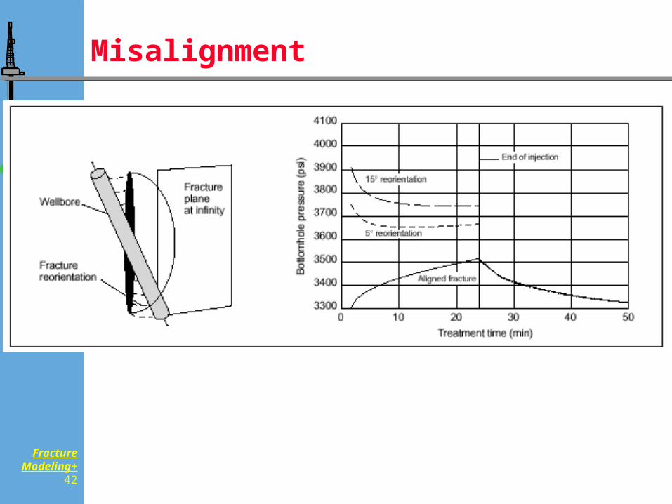
Misalignment
FractureModeling+
43
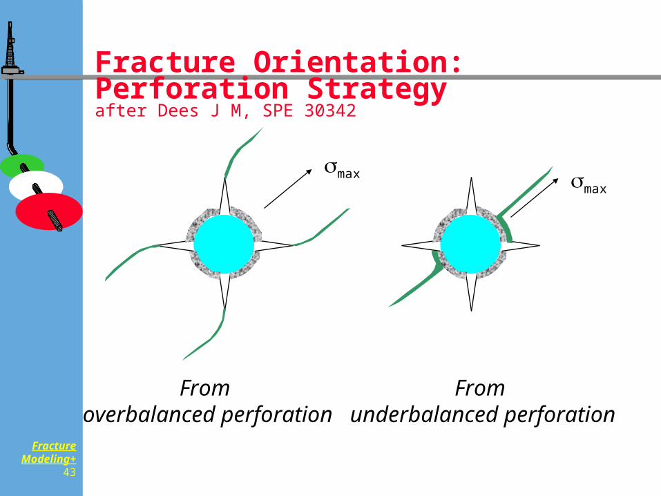
Fracture Orientation: Perforation Strategy after Dees J M, SPE 30342
max max
From overbalanced perforation
From underbalanced perforation
FractureModeling+
44
High Viscosity slugs
FractureModeling+
45
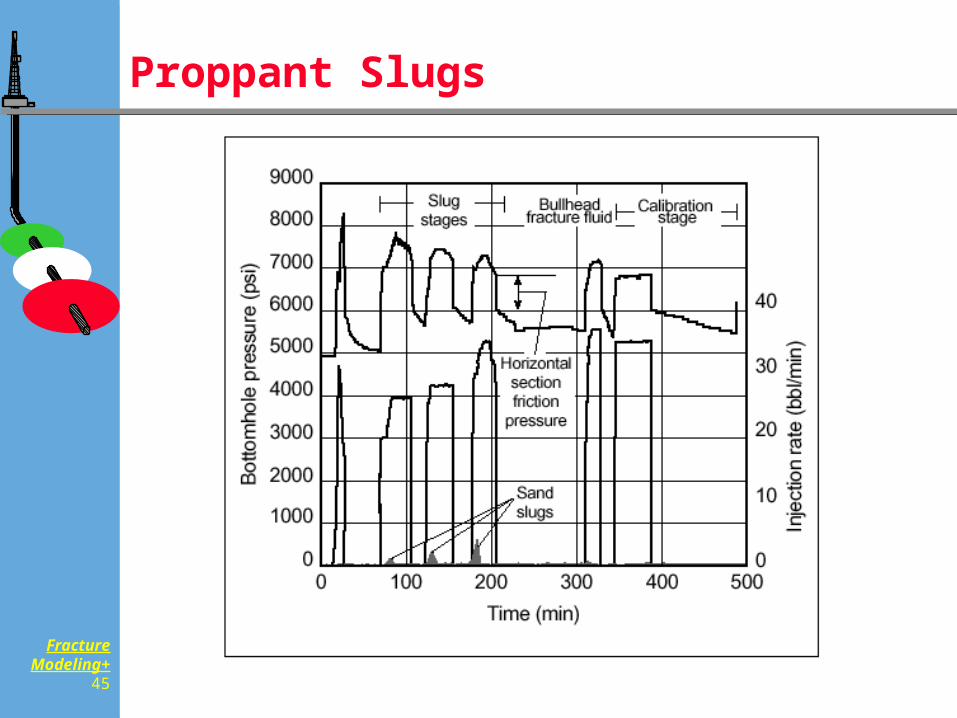
Proppant Slugs
FractureModeling+
46
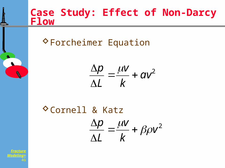
Forcheimer Equation
Cornell & Katz
Case Study: Effect of Non-Darcy Flow
2vkv
Lp
2avkv
Lp
FractureModeling+
47
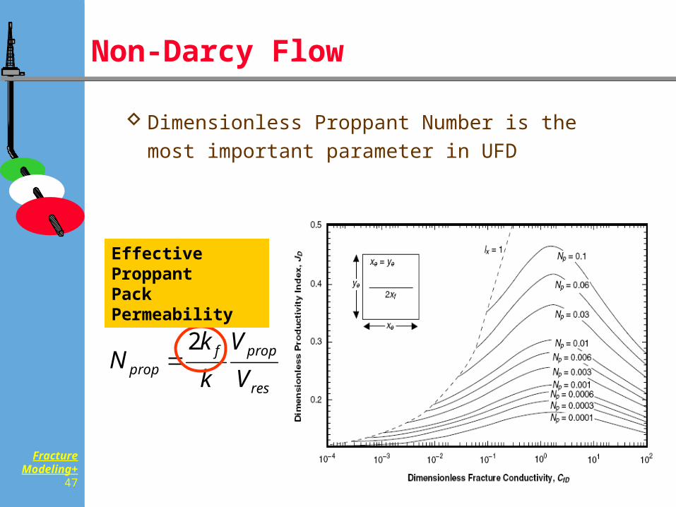
Non-Darcy Flow
Dimensionless Proppant Number is the most important parameter in UFD
res
propfprop V
Vkk
N2
Effective ProppantPack Permeability
FractureModeling+
48
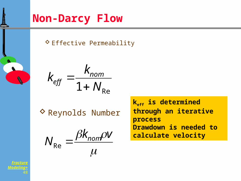
Non-Darcy Flow
Effective Permeability
Reynolds Number
Re1 Nkk nom
eff
vkN nomRe
keff is determined through an iterative processDrawdown is needed to calculate velocity
FractureModeling+
49
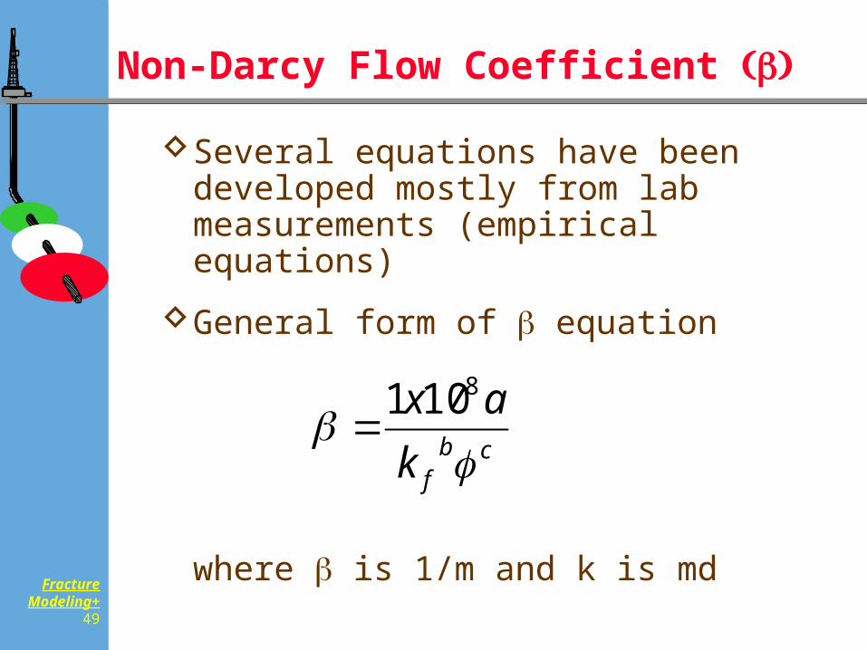
Non-Darcy Flow Coefficient
Several equations have been developed mostly from lab measurements (empirical equations)
General form of equation
where is 1/m and k is md
cbfk
ax
8101
FractureModeling+
50
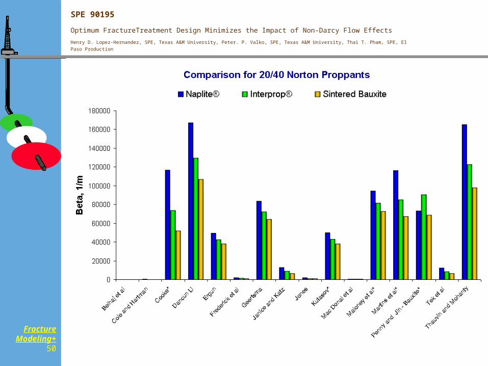
SPE 90195
Optimum FractureTreatment Design Minimizes the Impact of Non-Darcy Flow Effects
Henry D. Lopez-Hernandez, SPE, Texas A&M University, Peter. P. Valko, SPE, Texas A&M University, Thai T. Pham, SPE, El Paso Production
FractureModeling+
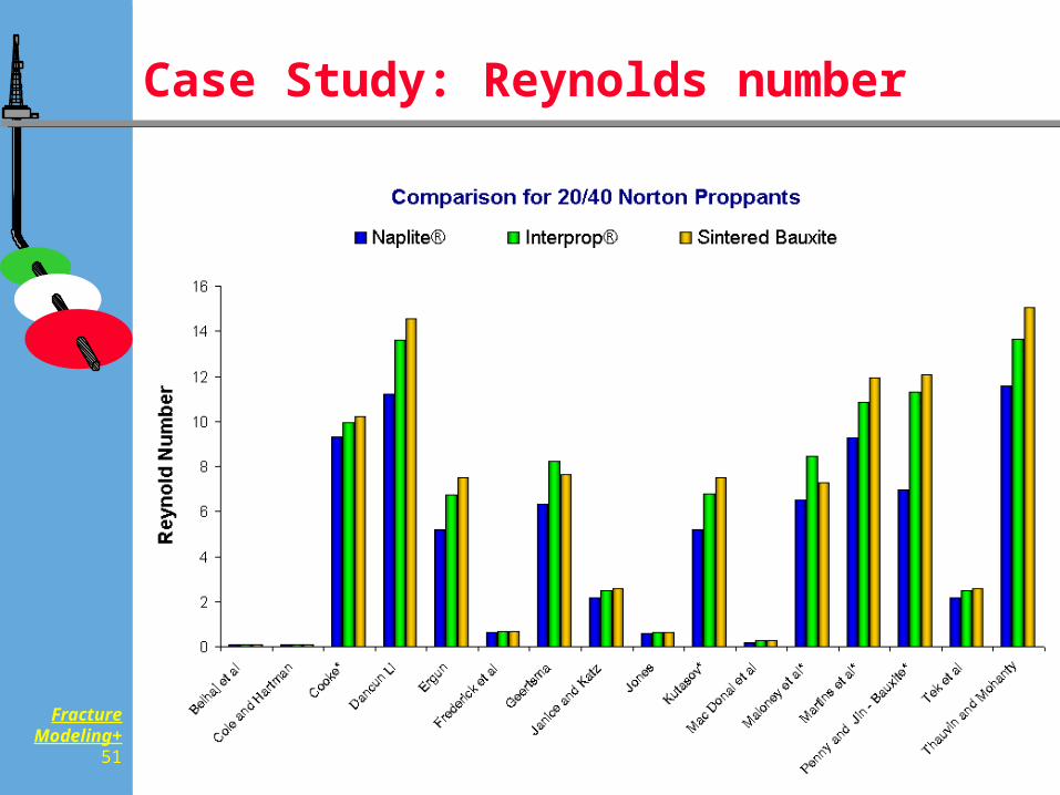
51
Case Study: Reynolds number
FractureModeling+
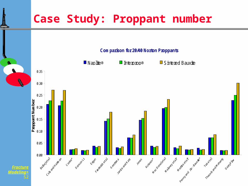
52
Case Study: Proppant number
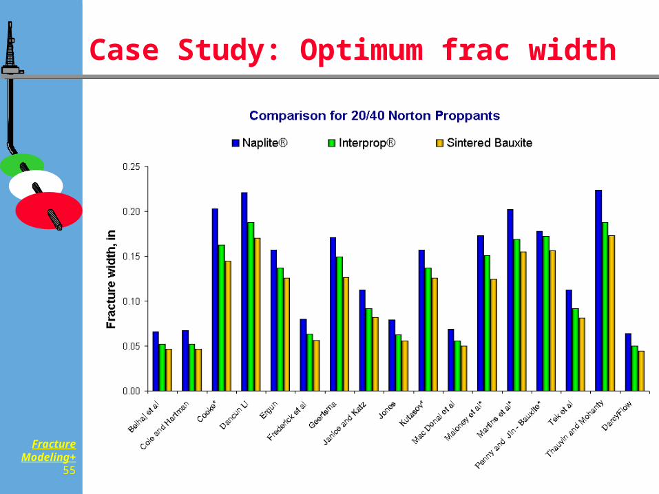
Comparison for 20/40 Norton Proppants
0.00
0.05
0.10
0.15
0.20
0.25
0.30
0.35
Prop
pant
Num
ber
Naplite® Interprop® Sintered Bauxite
FractureModeling+
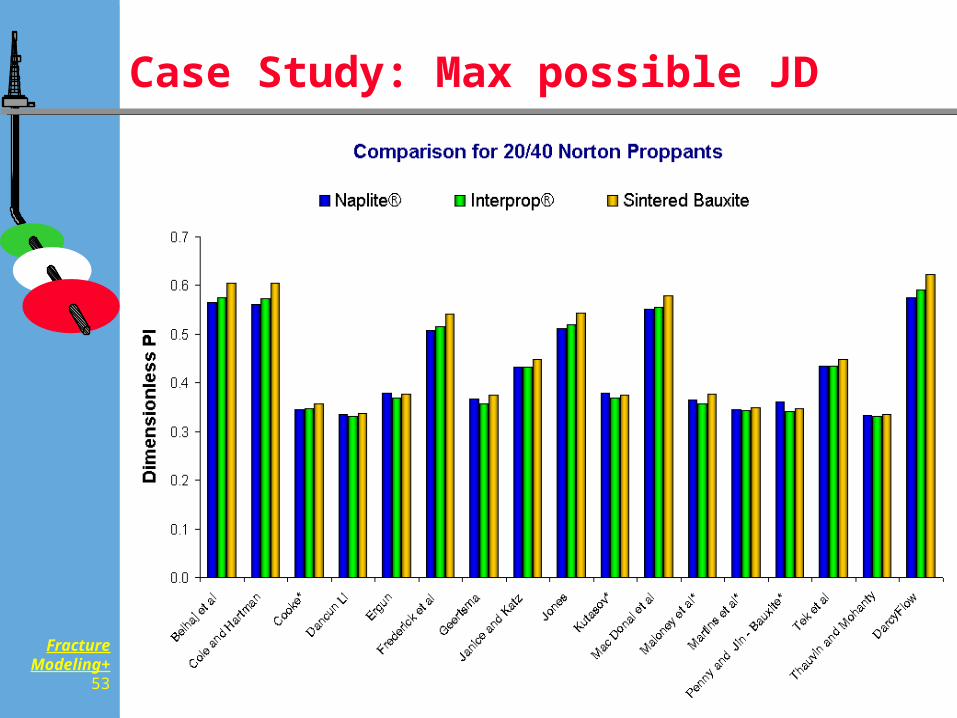
53
Case Study: Max possible JD
FractureModeling+
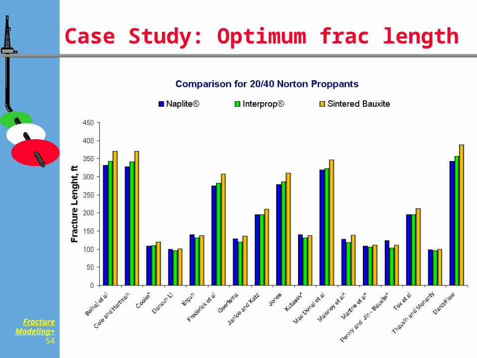
54
Case Study: Optimum frac length
FractureModeling+
55
Case Study: Optimum frac width
FractureModeling+
56
Summary
Increasing role of evaluation
Integration of reservoir engineering, production engineering and treatment information
Cost matters
Expensive 3D model does not substitute thinking
Still what we want to do is increasing JD


![[0] Kyusho Jitsu - Puntos de Acupuntura](https://static.fdocuments.nl/doc/165x107/55721315497959fc0b918fe0/0-kyusho-jitsu-puntos-de-acupuntura.jpg)