order P8049 NextGen Traptreden
47
CONSTRUCTIEBUREAU DE PROUW BV ADVIESBUREAU VOOR BOUWCONSTRUCTIES Vossegatsedijk 2a ● 3981 HS Bunnik ● T: 030 25 40 888 ● E: [email protected] NextGen Traptreden / NextGen Steps 1 order P8049 NextGen Traptreden NextGen Steps OPDRACHTGEVER / CLIENT EeStairs B.V. De Landweer 8 377 AA BARNEVELD - Netherlands CONSTRUCTEUR / STRUCTURAL ENGINEER Constructiebureau de Prouw BV Vossegatsedijk 2a 3981 HS BUNNIK - Netherlands +3130-2540888 [email protected] Bunnik, 19 augustus 2021
Transcript of order P8049 NextGen Traptreden
CONSTRUCTIEBUREAU DE PROUW BV
ADVIESBUREAU VOOR BOUWCONSTRUCTIES
Vossegatsedijk 2a ● 3981 HS Bunnik ● T: 030 25 40 888 ● E: [email protected]
NextGen Traptreden / NextGen Steps
1
order P8049
NextGen Traptreden NextGen Steps
OPDRACHTGEVER / CLIENT EeStairs B.V.
De Landweer 8
377 AA BARNEVELD - Netherlands
CONSTRUCTEUR / STRUCTURAL ENGINEER Constructiebureau de Prouw BV
Vossegatsedijk 2a
3981 HS BUNNIK - Netherlands
+3130-2540888
Bunnik, 19 augustus 2021
CONSTRUCTIEBUREAU DE PROUW BV
ADVIESBUREAU VOOR BOUWCONSTRUCTIES
Vossegatsedijk 2a ● 3981 HS Bunnik ● T: 030 25 40 888 ● E: [email protected]
NextGen Traptreden / NextGen Steps
2
INHOUDSOPGAVE
1. INLEIDING / INTRODUCTION .................................................................................................................... 3
2. UITGANGSPUNTEN TEST / ASSUMPTIONS TEST ................................................................................... 5
3. TESTRESULTATEN / TEST RESULTS ........................................................................................................ 8
4. CONCLUSIES / CONCLUSIONS ................................................................................................................ 9
BIJLAGE / ATTACHMENT A - TEST RAPPORT NEBEST B.V. / TEST REPORT NEBEST B.V.
BIJLAGE / ATTACHMENT B - EEM-BEREKENING / FEM-CALCULATION
CONSTRUCTIEBUREAU DE PROUW BV
ADVIESBUREAU VOOR BOUWCONSTRUCTIES
Vossegatsedijk 2a ● 3981 HS Bunnik ● T: 030 25 40 888 ● E: [email protected]
NextGen Traptreden / NextGen Steps
3
1. INLEIDING / INTRODUCTION
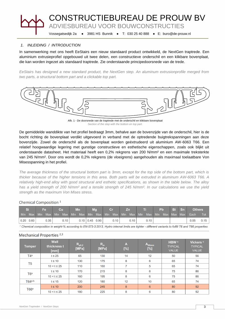
In samenwerking met ons heeft EeStairs een nieuw standaard product ontwikkeld, de NextGen traptrede. Een
aluminium extrusieprofiel opgebouwd uit twee delen, een constructieve onderschil en een klikbare bovenplaat,
die kan worden ingezet als standaard traptrede. Zie onderstaande principedoorsnede van de trede.
EeStairs has designed a new standard product, the NextGen step. An aluminum extrusionprofile merged from
two parts, a structural bottom part and a clickable top part.
De gemiddelde wanddikte van het profiel bedraagt 3mm, behalve aan de bovenzijde van de onderschil, hier is de
bocht richting de bovenplaat verdikt uitgevoerd in verband met de optredende buigtrekspanningen aan deze
bovenzijde. Zowel de onderschil als de bovenplaat worden geëxtrudeerd uit aluminium AW-6063 T66. Een
relatief hoogwaardige legering met gunstige constructieve en esthetische eigenschappen, zoals ook blijkt uit
onderstaande datasheet. Het materiaal heeft een 0,2% rekgrens van 200 N/mm² en een maximale treksterkte
van 245 N/mm². Door ons wordt de 0,2% rekgrens (de vloeigrens) aangehouden als maximaal toelaatbare Von
Misesspanning in het profiel.
The average thickness of the structural bottom part is 3mm, except for the top side of the bottom part, which is
thicker because of the higher tensions in this area. Both parts will be extruded in aluminum AW-6063 T66. A
relatively high-end alloy with good structural and esthetic specifications, as shown in the table below. The alloy
has a yield strength of 200 N/mm² and a tensile strength of 245 N/mm². In our calculations we use the yield
strength as the maximum Von Mises stress.
Afb. 1 - De doorsnede van de traptrede met de onderschil en klikbare bovenplaat
Section of the step with the bottom en top part.
CONSTRUCTIEBUREAU DE PROUW BV
ADVIESBUREAU VOOR BOUWCONSTRUCTIES
Vossegatsedijk 2a ● 3981 HS Bunnik ● T: 030 25 40 888 ● E: [email protected]
NextGen Traptreden / NextGen Steps
4
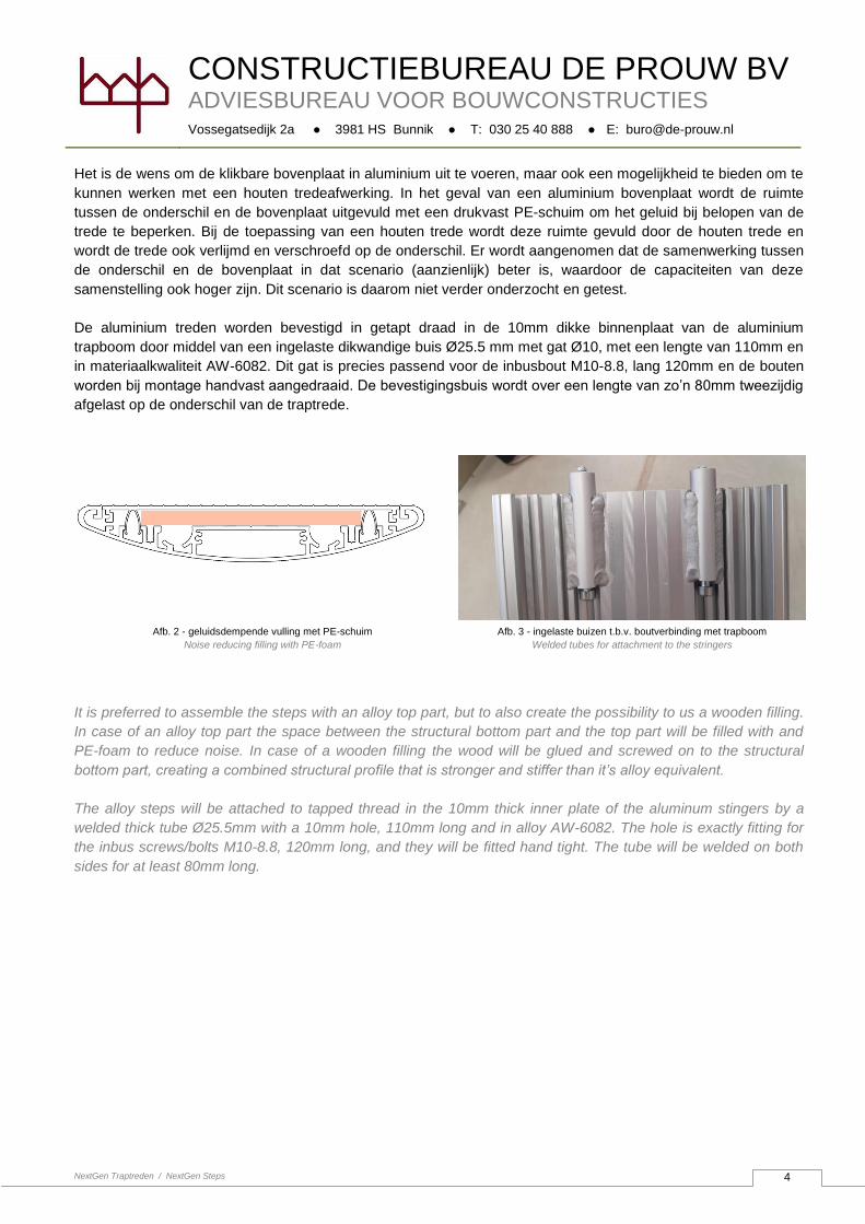
Het is de wens om de klikbare bovenplaat in aluminium uit te voeren, maar ook een mogelijkheid te bieden om te
kunnen werken met een houten tredeafwerking. In het geval van een aluminium bovenplaat wordt de ruimte
tussen de onderschil en de bovenplaat uitgevuld met een drukvast PE-schuim om het geluid bij belopen van de
trede te beperken. Bij de toepassing van een houten trede wordt deze ruimte gevuld door de houten trede en
wordt de trede ook verlijmd en verschroefd op de onderschil. Er wordt aangenomen dat de samenwerking tussen
de onderschil en de bovenplaat in dat scenario (aanzienlijk) beter is, waardoor de capaciteiten van deze
samenstelling ook hoger zijn. Dit scenario is daarom niet verder onderzocht en getest.
De aluminium treden worden bevestigd in getapt draad in de 10mm dikke binnenplaat van de aluminium
trapboom door middel van een ingelaste dikwandige buis Ø25.5 mm met gat Ø10, met een lengte van 110mm en
in materiaalkwaliteit AW-6082. Dit gat is precies passend voor de inbusbout M10-8.8, lang 120mm en de bouten
worden bij montage handvast aangedraaid. De bevestigingsbuis wordt over een lengte van zo’n 80mm tweezijdig
afgelast op de onderschil van de traptrede.
It is preferred to assemble the steps with an alloy top part, but to also create the possibility to us a wooden filling.
In case of an alloy top part the space between the structural bottom part and the top part will be filled with and
PE-foam to reduce noise. In case of a wooden filling the wood will be glued and screwed on to the structural
bottom part, creating a combined structural profile that is stronger and stiffer than it’s alloy equivalent.
The alloy steps will be attached to tapped thread in the 10mm thick inner plate of the aluminum stingers by a
welded thick tube Ø25.5mm with a 10mm hole, 110mm long and in alloy AW-6082. The hole is exactly fitting for
the inbus screws/bolts M10-8.8, 120mm long, and they will be fitted hand tight. The tube will be welded on both
sides for at least 80mm long.
Afb. 3 - ingelaste buizen t.b.v. boutverbinding met trapboom
Welded tubes for attachment to the stringers
Afb. 2 - geluidsdempende vulling met PE-schuim
Noise reducing filling with PE-foam
CONSTRUCTIEBUREAU DE PROUW BV
ADVIESBUREAU VOOR BOUWCONSTRUCTIES
Vossegatsedijk 2a ● 3981 HS Bunnik ● T: 030 25 40 888 ● E: [email protected]
NextGen Traptreden / NextGen Steps
5
2. UITGANGSPUNTEN TEST / ASSUMPTIONS TEST
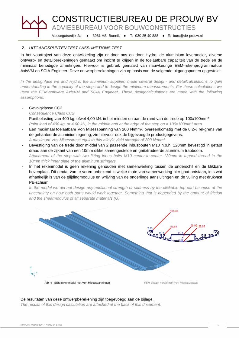
In het voortraject van deze ontwikkeling zijn er door ons en door Hydro, de aluminium leverancier, diverse
ontwerp- en detailberekeningen gemaakt om inzicht te krijgen in de toelaatbare capaciteit van de trede en de
minimaal benodigde afmetingen. Hiervoor is gebruik gemaakt van nauwkeurige EEM-rekenprogrammatuur
AxisVM en SCIA Engineer. Deze ontwerpberekeningen zijn op basis van de volgende uitgangspunten opgesteld:
In the designfase we and Hydro, the aluminium supplier, made several design- and detailcalculations to gain
understanding in the capacity of the steps and to design the minimum measurements. For these calculations we
used the FEM-software AxisVM and SCIA Engineer. These designcalculations are made with the following
assumptions:
- Gevolgklasse CC2
Consequence Class CC2
- Puntbelasting van 400 kg, ofwel 4,00 kN. in het midden en aan de rand van de trede op 100x100mm²
Point load of 400 kg, or 4,00 kN, in the middle and at the edge of the step on a 100x100mm² area
- Een maximaal toelaatbare Von Misesspanning van 200 N/mm², overeenkomstig met de 0,2% rekgrens van
de gehanteerde aluminiumlegering, zie hiervoor ook de bijgevoegde productgegevens.
A maximum Vos Misesstress equil to this alloy’s yield strenght of 200 N/mm²
- Bevestiging van de trede door middel van 2 passende inbusbouten M10 h.o.h. 120mm bevestigd in getapt
draad aan de zijkant van een 10mm dikke samengestelde en geëxtrudeerde aluminium trapboom.
Attachment of the step with two fitting inbus bolts M10 center-to-center 120mm in tapped thread in the
10mm thick inner plate of the aluminum stringers.
- In het rekenmodel is geen rekening gehouden met samenwerking tussen de onderschil en de klikbare
bovenplaat. Dit omdat van te voren onbekend is welke mate van samenwerking hier gaat ontstaan, iets wat
afhankelijk is van de glijdingmodulus en wrijving van de onderlinge aansluitingen en de vulling met drukvast
PE-schuim.
In the model we did not design any additional strength or stiffness by the clickable top part because of the
uncertainty on how both parts would work together. Something that is depended by the amount of friction
and the shearmodulus of all separate materials (G).
De resultaten van deze ontwerpberekening zijn toegevoegd aan de bijlage.
The results of this design calculation are attached at the back of this document.
Afb. 4 - EEM rekenmodel met Von Misesspanningen FEM design model with Von Misesstresses
CONSTRUCTIEBUREAU DE PROUW BV
ADVIESBUREAU VOOR BOUWCONSTRUCTIES
Vossegatsedijk 2a ● 3981 HS Bunnik ● T: 030 25 40 888 ● E: [email protected]
NextGen Traptreden / NextGen Steps
6
Aan de hand van deze ontwerpberekeningen is de exacte vorm van de trede vastgesteld en is een beeld
verkregen van de beschikbare sterkte en stijfheid, uitgaande van geen enkele samenwerking tussen onder- en
bovenkant van de trede. Om een meer realistisch beeld van de werkelijke sterkte en stijfheid te verkrijgen is
besloten om de maximale capaciteit en werkelijke stijfheid van de samengestelde treden vast te stellen door
middel van buigproeven. Door Nebest B.V. uit Vianen zijn deze buigproeven op 6 oktober 2020 uitgevoerd, zie
hiervoor de bijgevoegde testrapportage. De puntbelastingen zijn maatgevend voor de traptrede, en bij de
buigproef zijn deze als ongunstige aanname op de voorzijde van de traptrede geplaatst. In het rekenmodel was
hiervoor ook een belastinggeval opgenomen, maar deze gaf een onnauwkeurig beeld van plaatselijk spanningen.
With these calculations we have designed the exact shape of the steps and we provided intelligence on the
strength and stiffness of the structural bottom part, without the additional strength and stiffness of the top part. To
get a more realistic insight in the actual strength and stiffness of the steps, and the true cooperation between the
bottom and the top part, we decided to put the steps to the test by performing several one-point-bending tests on
the actual steps (aluminum structural bottom, PE-foam and aluminum top). ON the 6th of october 2020 Nebest
B.V. from Vianen performed the test, see attached test report for the results. The point loads are normative for
the steps and with the tests we’ve put the pointload (area of 100 x 100 m²) at the front of the steps, as an
unfavorable assumption. In the calculations we’ve also performed this eccentric load but this only showed us the
all-over tensions in het profile, but not the local tensions just below the point load.
CONSTRUCTIEBUREAU DE PROUW BV
ADVIESBUREAU VOOR BOUWCONSTRUCTIES
Vossegatsedijk 2a ● 3981 HS Bunnik ● T: 030 25 40 888 ● E: [email protected]
NextGen Traptreden / NextGen Steps
7
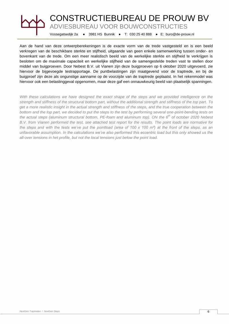
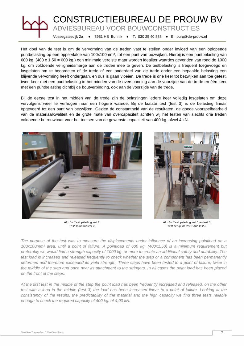
Het doel van de test is om de vervorming van de treden vast te stellen onder invloed van een oplopende
puntbelasting op een oppervlakte van 100x100mm², tot een punt van bezwijken. Hierbij is een puntbelasting van
600 kg. (400 x 1,50 = 600 kg.) een minimale vereiste maar worden idealiter waardes gevonden van rond de 1000
kg. om voldoende veiligheidsmarge aan de treden mee te geven. De testbelasting is frequent toegevoegd en
losgelaten om te beoordelen of de trede of een onderdeel van de trede onder een bepaalde belasting een
blijvende vervorming heeft ondergaan, en dus is gaan vloeien. De trede is drie keer tot bezwijken aan toe getest,
twee keer met een puntbelasting in het midden van de overspanning aan de voorzijde van de trede en één keer
met een puntbelasting dichtbij de boutverbinding, ook aan de voorzijde van de trede.
Bij de eerste test in het midden van de trede zijn de belastingen iedere keer volledig losgelaten om deze
vervolgens weer te verhogen naar een hogere waarde. Bij de laatste test (test 3) is de belasting lineair
opgevoerd tot een punt van bezwijken. Gezien de constantheid van de resultaten, de goede voorspelbaarheid
van de materiaalkwaliteit en de grote mate van overcapaciteit achtten wij het testen van slechts drie treden
voldoende betrouwbaar voor het toetsen van de gewenste capaciteit van 400 kg. ofwel 4 kN.
The purpose of the test was to measure the displacements under influence of an increasing pointload on a
100x100mm² area, until a point of failure. A pointload of 600 kg. (400x1,50) is a minimum requirement but
preferably we would find a strength capacity of 1000 kg. or more to create an additional safety and durability. The
test load is increased and released frequently to check whether the step or a component has been permanently
deformed and therefore exceeded its yield strength. Three steps have been tested to a point of failure, twice in
the middle of the step and once near its attachment to the stringers. In all cases the point load has been placed
on the front of the steps.
At the first test in the middle of the step the point load has been frequently increased and released, on the other
test with a load in the middle (test 3) the load has been increased linear to a point of failure. Looking at the
consistency of the results, the predictability of the material and the high capacity we find three tests reliable
enough to check the required capacity of 400 kg. of 4,00 kN.
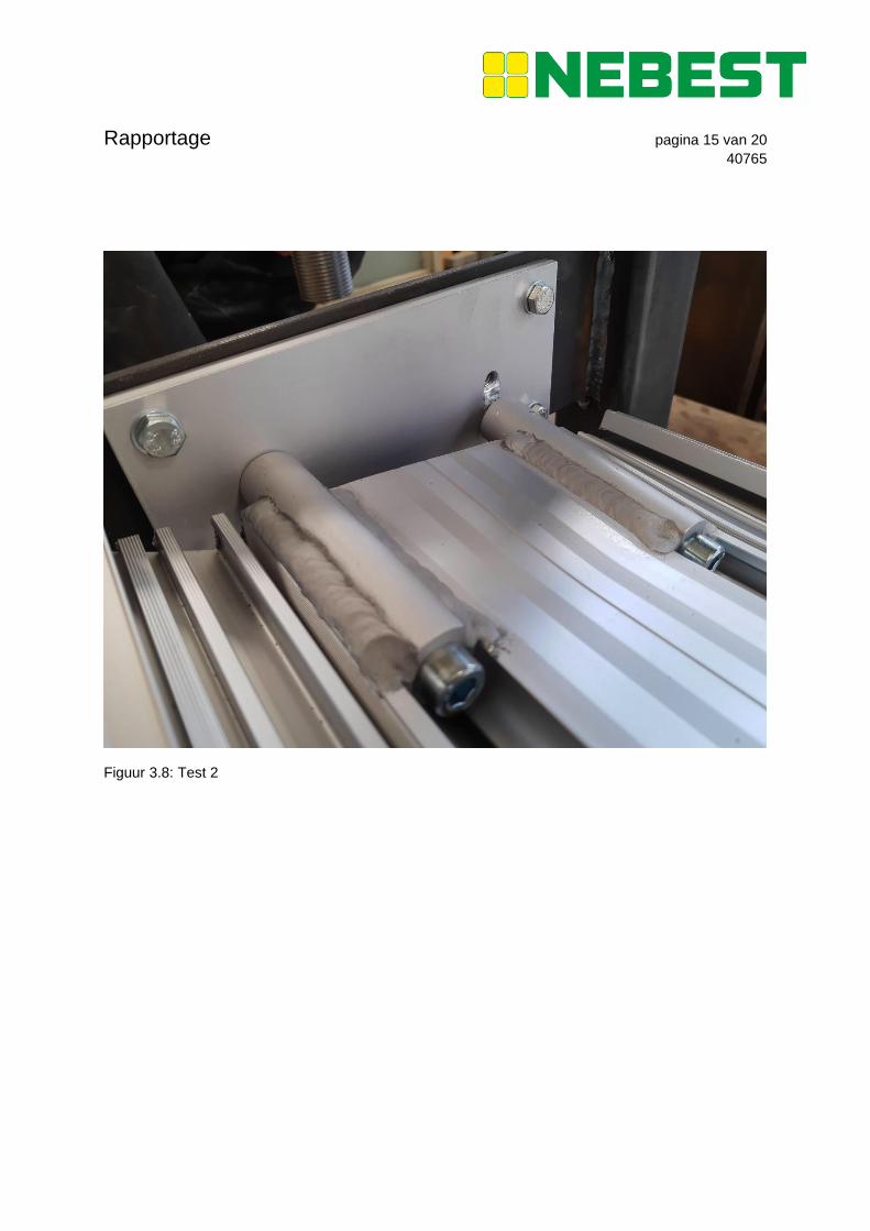
Afb. 5 - Testopstelling test 2
Test setup for test 2
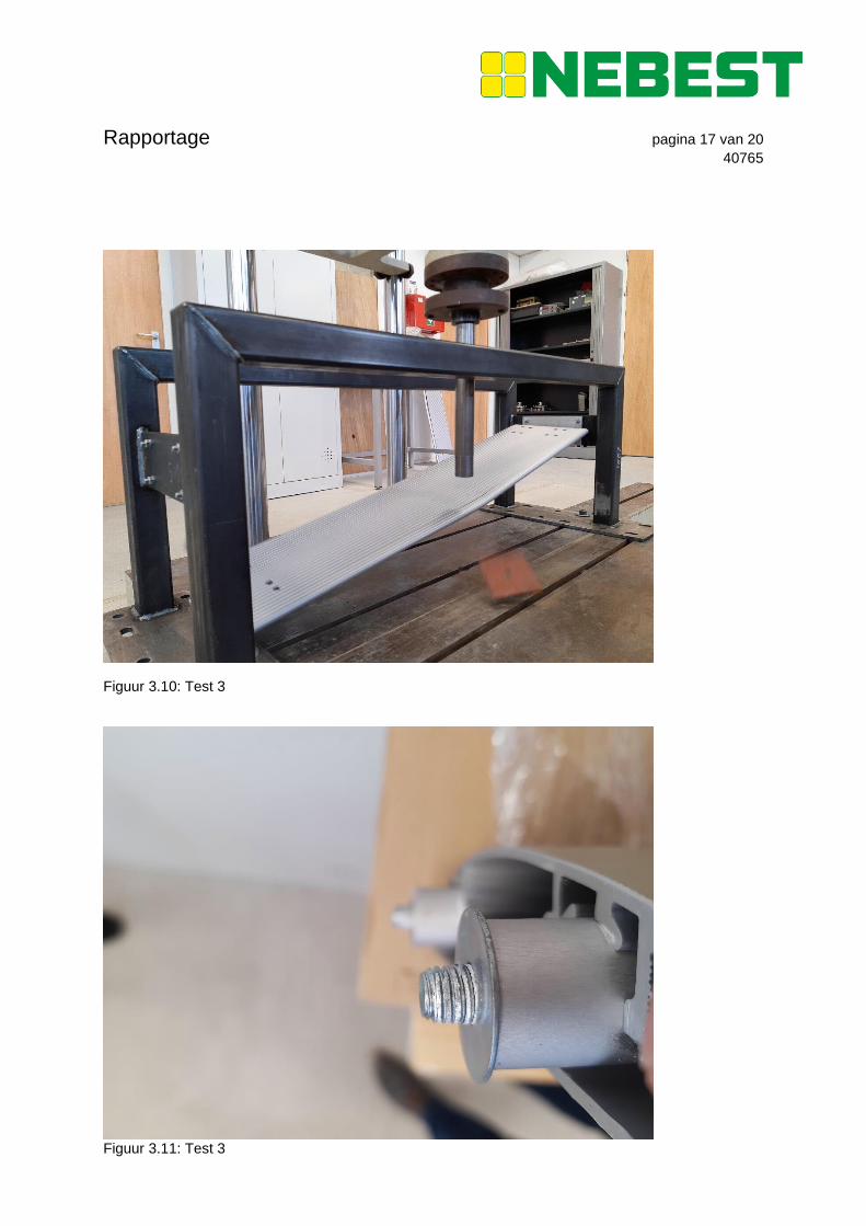
Afb. 6 - Testopstelling test 1 en test 3
Test setup for test 1 and test 3
CONSTRUCTIEBUREAU DE PROUW BV
ADVIESBUREAU VOOR BOUWCONSTRUCTIES
Vossegatsedijk 2a ● 3981 HS Bunnik ● T: 030 25 40 888 ● E: [email protected]
NextGen Traptreden / NextGen Steps
8
3. TESTRESULTATEN / TEST RESULTS
TEST 1 TEST 2 TEST 3
Locatie puntlast
Location pointload
Midden, aan voorzijde
Centre, at the front
Zijkant, aan de voorzijde
Side, at the front
Midden, aan de voorzijde
Centre, at the front
Belasting bij eerste blijvende
vervorming (vloeigrens)
Load at first permanent
deformation (yield strenght)
8,00 kN. 10,00 kN. Niet gemeten / not measured
Doorbuiging bij eerste blijvende
vervorming
Displacement at first permanent
deformation
16mm, (1mm permanente
doorbuiging)
16mm (1mm permanent
deformation)
4,80mm, (1mm permanente
doorbuiging)
4,80mm (1mm permanent
deformation)
niet gemeten / not measured
Belasting bij bezwijken
Load at failure
15,90 kN. 27,40 kN. 16,70kN.
Verplaatsing bij bezwijken
Displacement at failure
46mm 26mm 69mm
Bezwijkmechanisme
Point of failure
Het vloeien van, en daardoor de
koordwerking in, de trede
waardoor de bout het draad in
de alu-boom kapot heeft
getrokken.
Exceedance of the yield
strength, with boltfailure as
result of the large deformation.
Boutbreuk en stuiken alu-
trapboom.
Bolt failure and failure of the
thread in the stairstringer
Het vloeien van, en daardoor de
koordwerking in, de trede
waardoor de bout het draad in
de alu-boom kapot heeft
getrokken.
Exceedance of the yield
strength, with boltfailure as
result of the large deformation
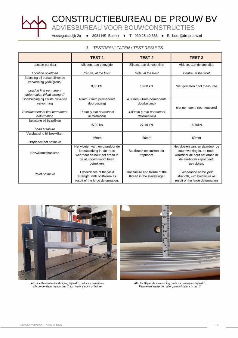
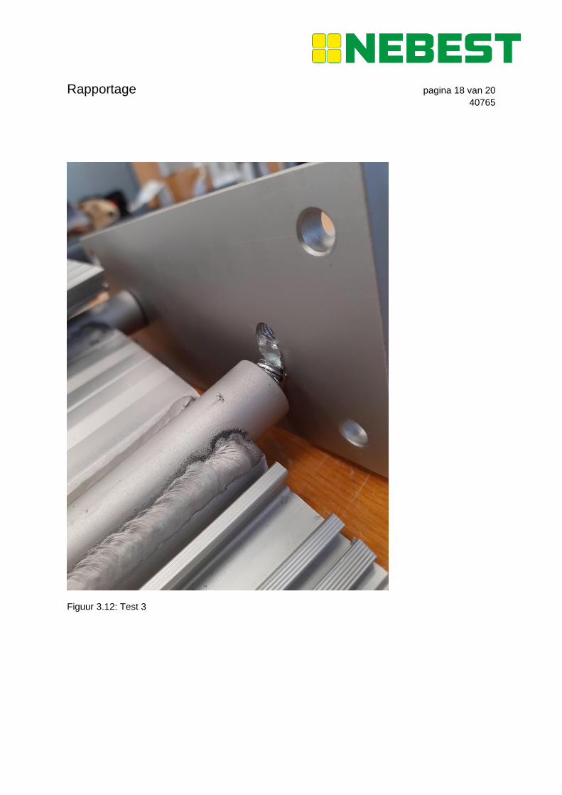
Afb. 8 - Blijvende vervorming trede na bezwijken bij test 3 Permanent deflection after point of failure in test 3
Afb. 7 - Maximale doorbuiging bij test 3, net voor bezwijken Maximum deformation test 3, just before point of failure
CONSTRUCTIEBUREAU DE PROUW BV
ADVIESBUREAU VOOR BOUWCONSTRUCTIES
Vossegatsedijk 2a ● 3981 HS Bunnik ● T: 030 25 40 888 ● E: [email protected]
NextGen Traptreden / NextGen Steps
9
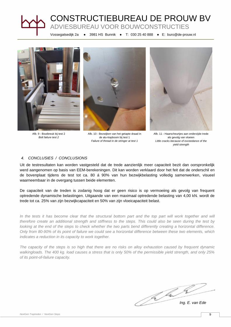
4. CONCLUSIES / CONCLUSIONS
Uit de testresultaten kan worden vastgesteld dat de trede aanzienlijk meer capaciteit bezit dan oorspronkelijk
werd aangenomen op basis van EEM-berekeningen. Dit kan worden verklaard door het feit dat de onderschil en
de bovenplaat tijdens de test tot ca. 80 á 90% van hun bezwijkbelasting volledig samenwerken, visueel
waarneembaar in de overgang tussen beide elementen.
De capaciteit van de treden is zodanig hoog dat er geen risico is op vermoeiing als gevolg van frequent
optredende dynamische belastingen. Uitgaande van een maximaal optredende belasting van 4,00 kN. wordt de
trede tot ca. 25% van zijn bezwijkcapaciteit en 50% van zijn vloeicapaciteit belast.
In the tests it has become clear that the structural bottom part and the top part will work together and will
therefore create an additional strength and stiffness to the steps. This could also be seen during the test by
looking at the end of the steps to check whether the two parts bend differently creating a horizontal difference.
Only from 80-90% of its point of failure we could see a horizontal difference between these two elements, which
indicates a reduction in its capacity to work together.
The capacity of the steps is so high that there are no risks on alloy exhaustion caused by frequent dynamic
walkingloads. The 400 kg. load causes a stress that is only 50% of the permissible yield strength, and only 25%
of its point-of-failure capacity.
Ing. E. van Ede
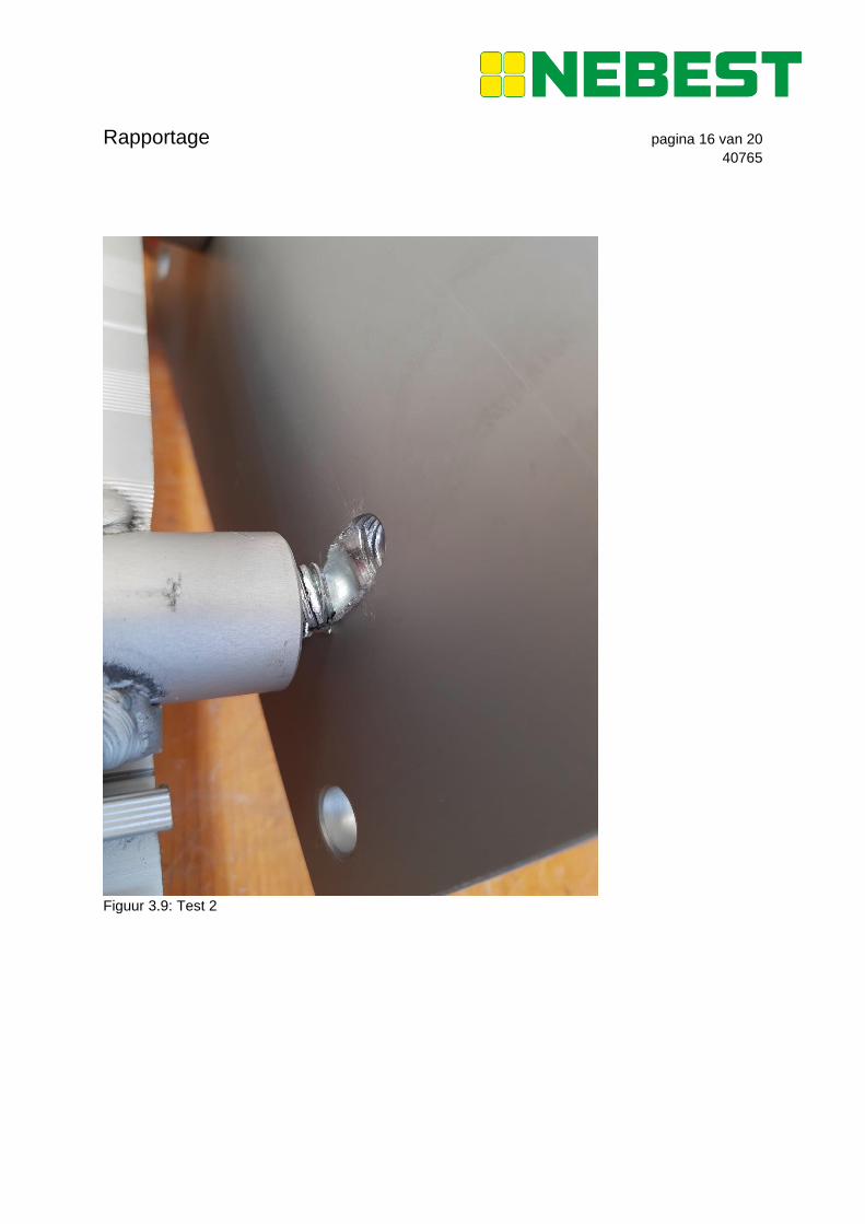
Afb. 9 - Boutbreuk bij test 2
Bolt failure test 2
Afb. 10 - Bezwijken van het getapte draad in
de alu-trapboom bij test 1
Failure of thread in de stringer at test 1
Afb. 11 - Haarscheurtjes aan onderzijde trede
als gevolg van vloeien
Little cracks because of exceedance of the
yield strength
Rapportage
IBAN NL47 RABO 0171 7681 67 | BIC RABONL2U | BTW NL008929439B01 | HR 23046375
Op al onze werkzaamheden is de ‘Rechtsverhouding opdrachtgever - architect, ingenieur en adviseur DNR 2011’ van toepassing.
Deze voorwaarden liggen op ons kantoor ter inzage en zijn ook in te zien op onze website (www.nebest.nl).
Nebest B.V.
Marconiweg 2
4131 PD Vianen
Postbus 106
4130 EC Vianen
T
F
E
I
085 489 01 00
085 489 01 01
www.nebest.nl
Project : NextGen
Opdrachtgever : EeStairs
Rapportnummer : 40765
Datum : 15 oktober 2020
Betreft : Beproeving NextGen traptredes / Testing NextGen treads
1 INLEIDING / INTRODUCTION
EeStairs heeft een nieuw standaardproduct ontwikkeld, de NextGen. Dit is een designtrap bestaande
uit aluminium extrusieprofielen. Om inzicht te krijgen in de krachten die dit ontwerp op kan nemen
heeft EeStairs het laboratorium van Nebest B.V. opdracht gegeven een aantal van deze traptreden op
druk te belasten.
EeStairs has developed a new standard product, the NextGen. This is a design staircase made of
aluminium extrusion profiles. In order to gain insight into the forces the treads can absorb, EeStairs
has commissioned the laboratory of Nebest B.V. to perform a series of loading tests.
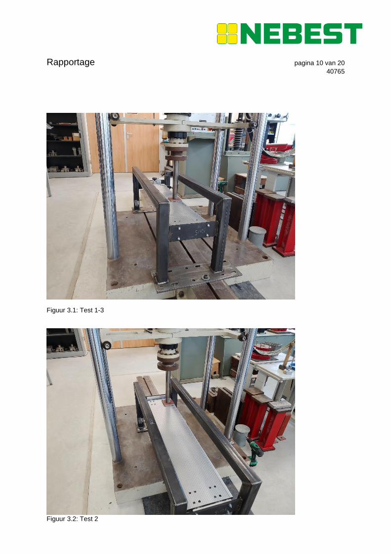
2 METHODE / METHOD
Om de traptreden te beproeven, heeft de opdrachtgever een opstelling gefabriceerd welke gefixeerd
kan worden op de drukbank. Voor alle tests is als drukvlak een stalen plaat gebruikt van 100 x 100
mm. Tijdens de eerste test is in het midden van een traptrede, op de rand, de druk opgevoerd in
stappen van 0,5 kN met een snelheid van 0,1 kN/s tot bezwijken (fotobijlage Figuur 3.1). Tussentijds is
bij 8, 10, 12 en 14 kN de druk van de trede afgelaten om de blijvende vervorming te meten.
De tweede test is gelijkwaardig uitgevoerd aan de eerste test, maar 10 cm uit de zijkant, wederom op
de rand (fotobijlage Figuur 3.2). Hierbij is tussentijds 10, 12, 14, 16, 20 en 24 kN de druk van de trede
afgelaten om de blijvende vervorming te meten.
De derde test is op dezelfde locatie uitgevoerd als de eerste test. De druk is tijdens deze test continue
opgevoerd met 0,2 kN/s tot bezwijken.
For the tests EeStairs has fabricated a set-up that could be fixated to the test bench. For all tests a
steel pressure plate measuring 100 x 100 mm was used. For the first test, in the middle of the tread,
on the edge, the pressure was increased in steps of 0,5 kN with a speed of 0,1 kN/s until failure (photo
attachment Figure 3.1). During the test, at 8, 10, 12 and 14 kN the pressure was released to measure
permanent deformation.
The second test was performed similarly to the first test but 10 cm from the side, also on the edge
(photo attachment Figure 3.2). During the test, at 10, 12, 14, 16, 20 and 24 kN the pressure was
released to measure permanent deformation.
The location on the thread for the third test was the same as the first test. During the third test the
pressure was continuously increased with 0,2 kN/s until failure.
Egbert van Ede
Tekstvak
BIJLAGE / ATTACHMENT A
Rapportage pagina 2 van 20
40765
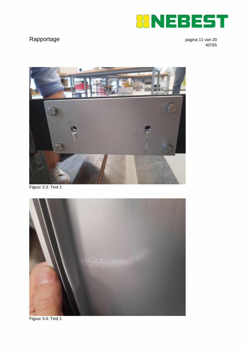
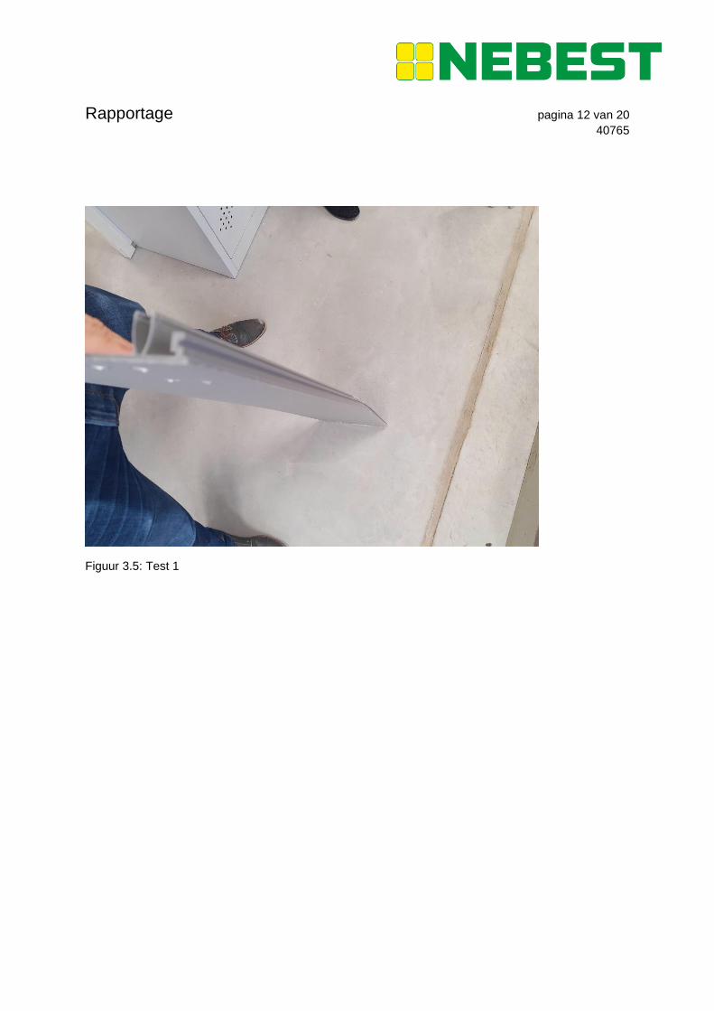
3 RESULTATEN / RESULTS
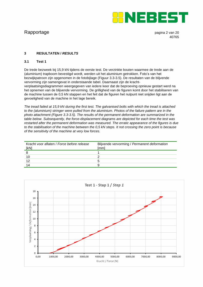
3.1 Test 1
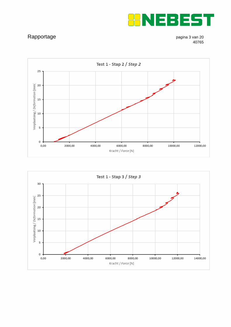
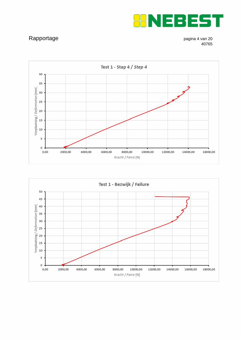
De trede bezweek bij 15,9 kN tijdens de eerste test. De verzinkte bouten waarmee de trede aan de
(aluminium) trapboom bevestigd wordt, werden uit het aluminium getrokken. Foto’s van het
bezwijkpatroon zijn opgenomen in de fotobijlage (Figuur 3.3-3.5). De resultaten van de blijvende
vervorming zijn samengevat in onderstaande tabel. Daarnaast zijn de kracht-
verplaatsingsdiagrammen weergegeven van iedere keer dat de beproeving opnieuw gestart werd na
het opnemen van de blijvende vervorming. De grilligheid van de figuren komt door het stabiliseren van
de machine tussen de 0,5 kN stappen en het feit dat de figuren het nulpunt niet snijden ligt aan de
gevoeligheid van de machine in het lage bereik.
The tread failed at 15,9 kN during the first test. The galvanised bolts with which the tread is attached
to the (aluminium) stringer were pulled from the aluminium. Photos of the failure pattern are in the
photo attachment (Figure 3.3-3.5). The results of the permanent deformation are summarized in the
table below. Subsequently, the force-displacement diagrams are depicted for each time the test was
restarted after the permanent deformation was measured. The erratic appearance of the figures is due
to the stabilisation of the machine between the 0,5 kN steps. It not crossing the zero point is because
of the sensitivity of the machine at very low forces.
Kracht voor aflaten / Force before release
[kN]
Blijvende vervorming / Permanent deformation
[mm]
8 1
10 2
12 5
14 9
Rapportage pagina 3 van 20
40765
Rapportage pagina 4 van 20
40765
Rapportage pagina 5 van 20
40765
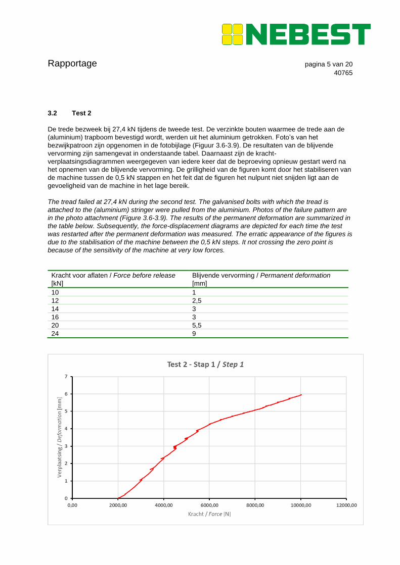
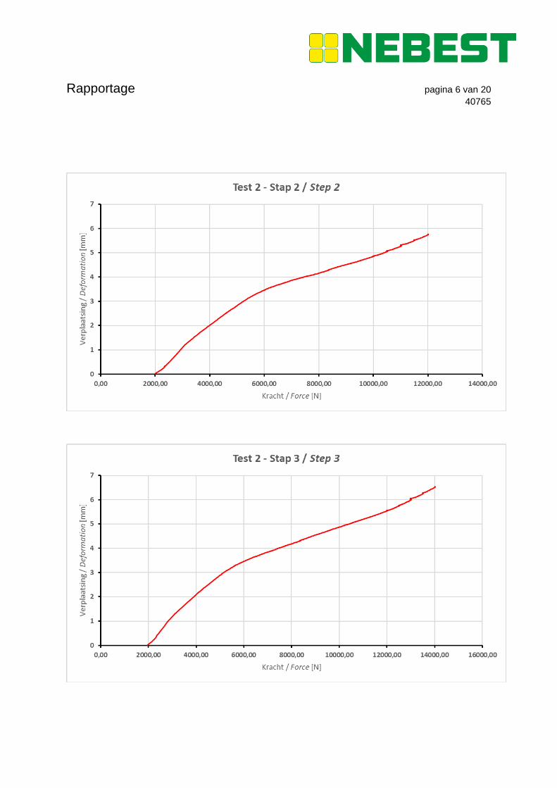
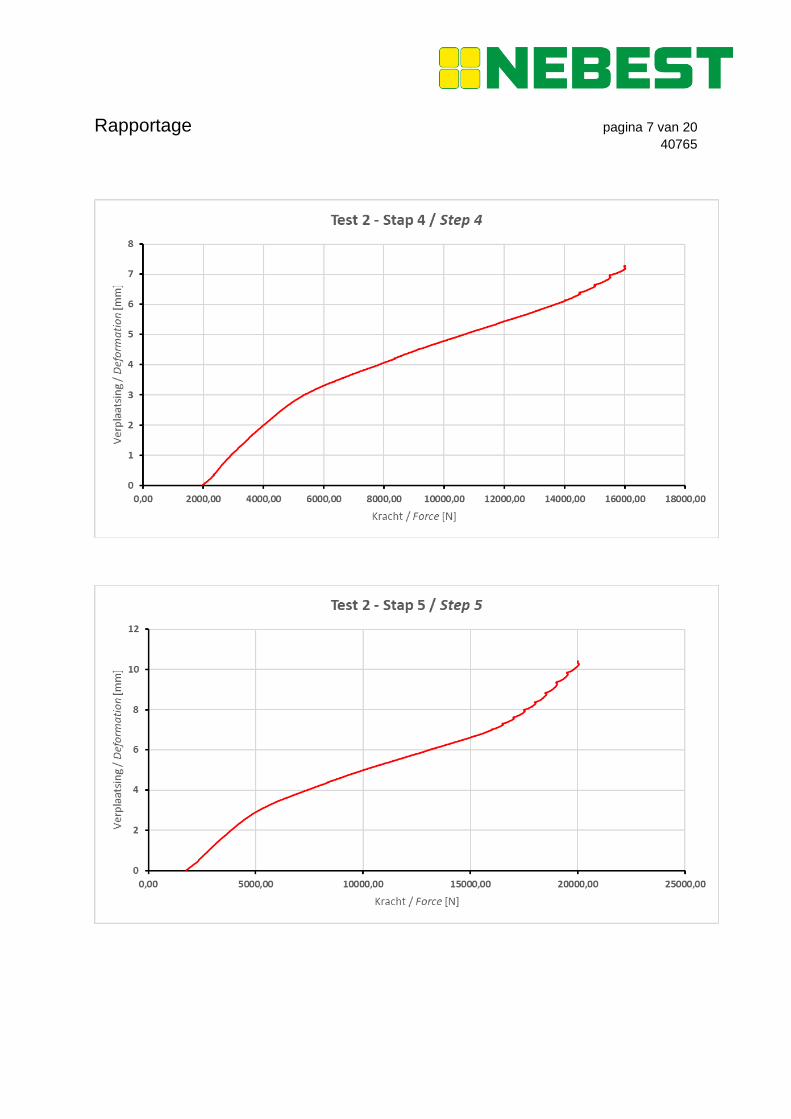
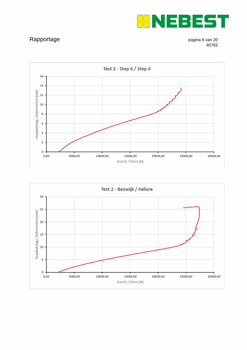
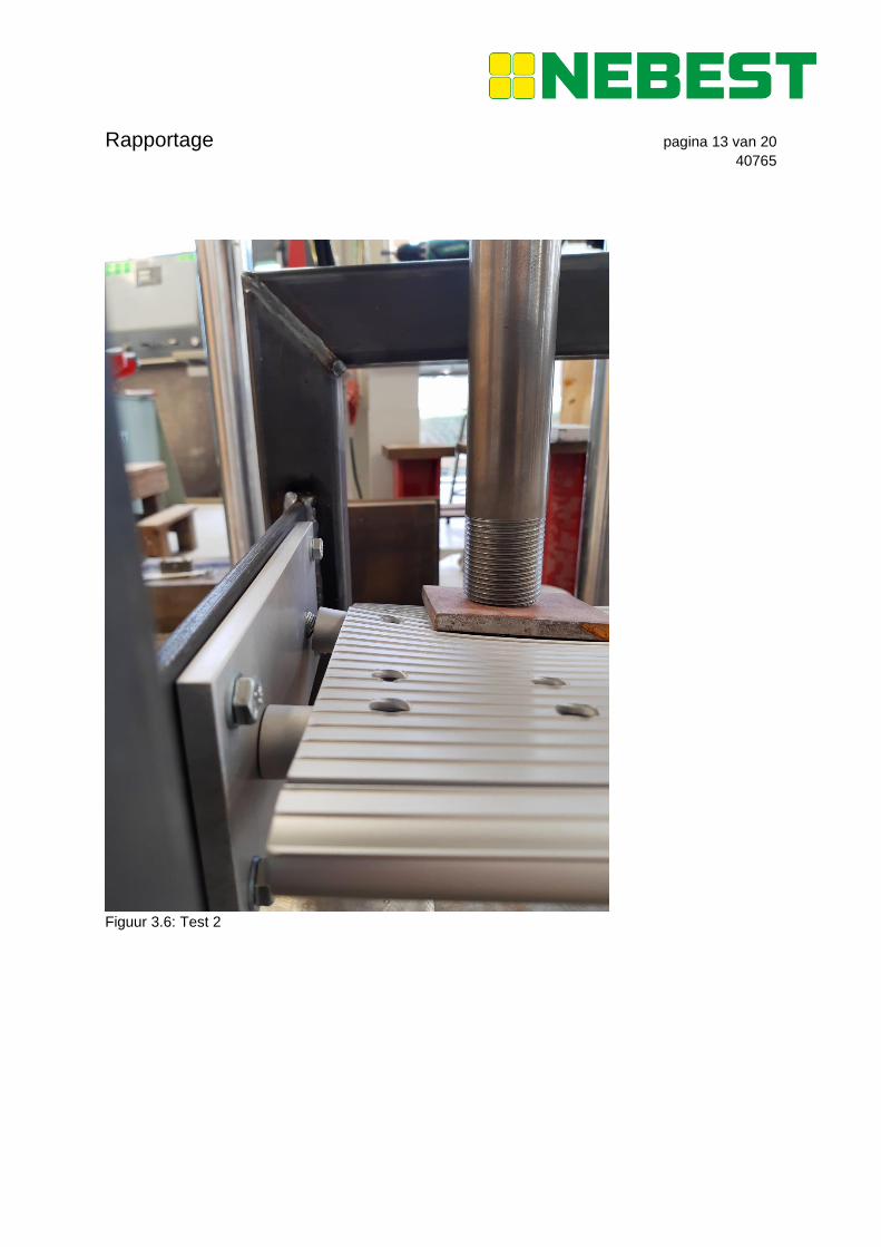
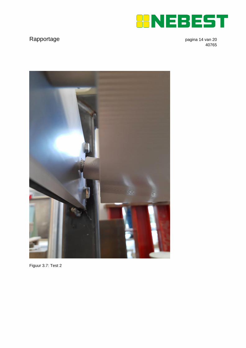
3.2 Test 2
De trede bezweek bij 27,4 kN tijdens de tweede test. De verzinkte bouten waarmee de trede aan de
(aluminium) trapboom bevestigd wordt, werden uit het aluminium getrokken. Foto’s van het
bezwijkpatroon zijn opgenomen in de fotobijlage (Figuur 3.6-3.9). De resultaten van de blijvende
vervorming zijn samengevat in onderstaande tabel. Daarnaast zijn de kracht-
verplaatsingsdiagrammen weergegeven van iedere keer dat de beproeving opnieuw gestart werd na
het opnemen van de blijvende vervorming. De grilligheid van de figuren komt door het stabiliseren van
de machine tussen de 0,5 kN stappen en het feit dat de figuren het nulpunt niet snijden ligt aan de
gevoeligheid van de machine in het lage bereik.
The tread failed at 27,4 kN during the second test. The galvanised bolts with which the tread is
attached to the (aluminium) stringer were pulled from the aluminium. Photos of the failure pattern are
in the photo attachment (Figure 3.6-3.9). The results of the permanent deformation are summarized in
the table below. Subsequently, the force-displacement diagrams are depicted for each time the test
was restarted after the permanent deformation was measured. The erratic appearance of the figures is
due to the stabilisation of the machine between the 0,5 kN steps. It not crossing the zero point is
because of the sensitivity of the machine at very low forces.
Kracht voor aflaten / Force before release
[kN]
Blijvende vervorming / Permanent deformation
[mm]
10 1
12 2,5
14 3
16 3
20 5,5
24 9
Rapportage pagina 6 van 20
40765
Rapportage pagina 7 van 20
40765
Rapportage pagina 8 van 20
40765
Rapportage pagina 9 van 20
40765
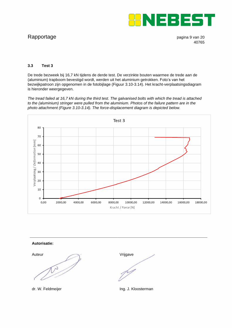
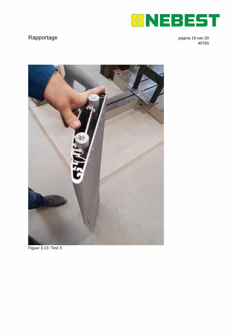
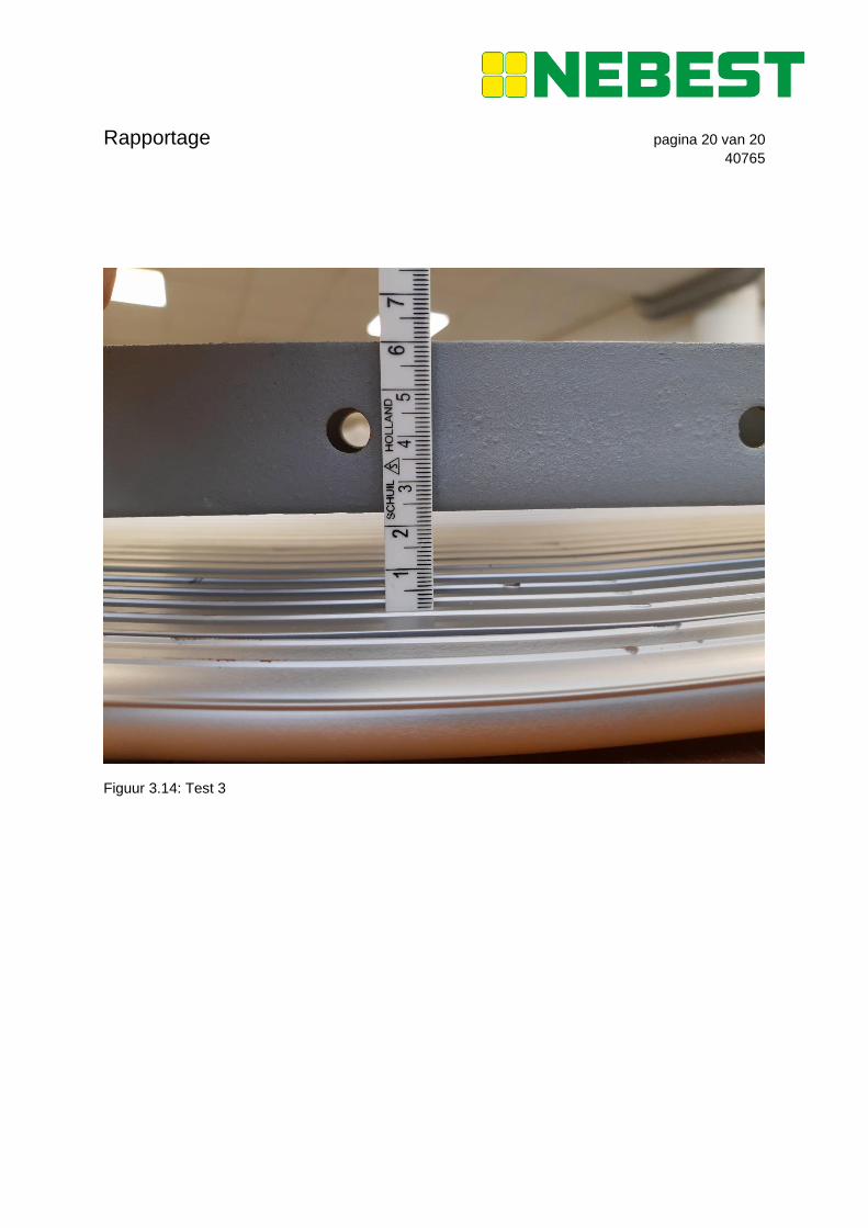
3.3 Test 3
De trede bezweek bij 16,7 kN tijdens de derde test. De verzinkte bouten waarmee de trede aan de
(aluminium) trapboom bevestigd wordt, werden uit het aluminium getrokken. Foto’s van het
bezwijkpatroon zijn opgenomen in de fotobijlage (Figuur 3.10-3.14). Het kracht-verplaatsingsdiagram
is hieronder weergegeven.
The tread failed at 16,7 kN during the third test. The galvanised bolts with which the tread is attached
to the (aluminium) stringer were pulled from the aluminium. Photos of the failure pattern are in the
photo attachment (Figure 3.10-3.14). The force-displacement diagram is depicted below.
Autorisatie:
Auteur Vrijgave
dr. W. Feldmeijer Ing. J. Kloosterman
Rapportage pagina 10 van 20
40765
Figuur 3.1: Test 1-3
Figuur 3.2: Test 2
Rapportage pagina 11 van 20
40765
Figuur 3.3: Test 1
Figuur 3.4: Test 1
Rapportage pagina 12 van 20
40765
Figuur 3.5: Test 1
Rapportage pagina 13 van 20
40765
Figuur 3.6: Test 2
Rapportage pagina 14 van 20
40765
Figuur 3.7: Test 2
Rapportage pagina 15 van 20
40765
Figuur 3.8: Test 2
Rapportage pagina 16 van 20
40765
Figuur 3.9: Test 2
Rapportage pagina 17 van 20
40765
Figuur 3.10: Test 3
Figuur 3.11: Test 3
Rapportage pagina 18 van 20
40765
Figuur 3.12: Test 3
Rapportage pagina 19 van 20
40765
Figuur 3.13: Test 3
Rapportage pagina 20 van 20
40765
Figuur 3.14: Test 3
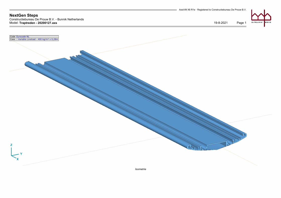
AxisVM X6 R1e · Registered to Constructiebureau De Prouw B.V.
NextGen StepsConstructiebureau De Prouw B.V. - Bunnik Netherlands
Page 119-8-2021Model: Traptreden - 20200127.axs
Code Eurocode-NLCase : Variable Lineload - 400 kg/m² x 0,28m
Isometrie
Egbert van Ede
Tekstvak
BIJLAGE / ATTACHMENT B
AxisVM X6 R1e · Registered to Constructiebureau De Prouw B.V.
NextGen StepsConstructiebureau De Prouw B.V. - Bunnik Netherlands
Page 219-8-2021Model: Traptreden - 20200127.axs
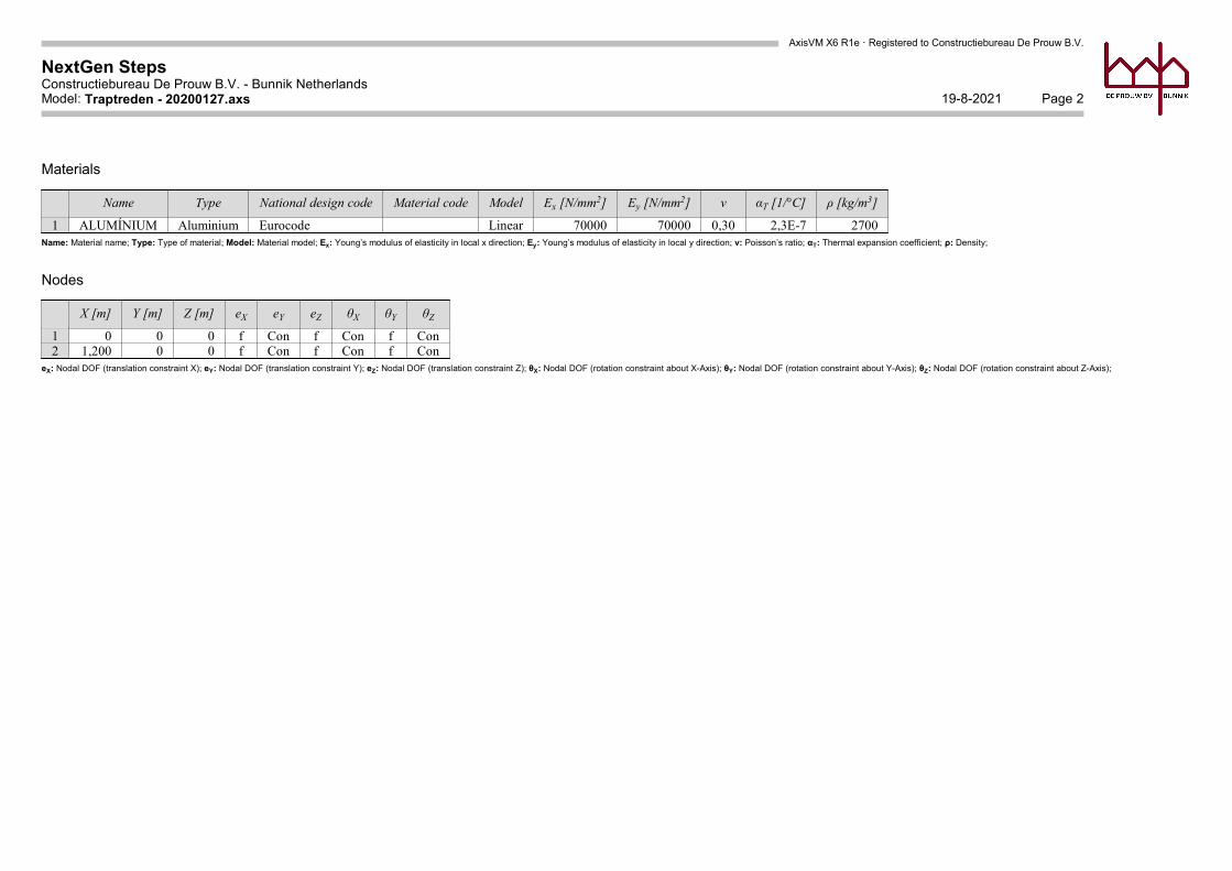
Materials
Name Type National design code Material code Model Ex [N/mm2] Ey [N/mm2] ν αT [1/°C] ρ [kg/m3]
1 ALUMÍNIUM Aluminium Eurocode Linear 70000 70000 0,30 2,3E-7 2700Name: Material name; Type: Type of material; Model: Material model; Ex: Young’s modulus of elasticity in local x direction; Ey: Young’s modulus of elasticity in local y direction; ν: Poisson’s ratio; αT: Thermal expansion coefficient; ρ: Density;
Nodes
X [m] Y [m] Z [m] eX eY eZ θX θY θZ
1 0 0 0 f Con f Con f Con2 1,200 0 0 f Con f Con f Con
eX: Nodal DOF (translation constraint X); eY: Nodal DOF (translation constraint Y); eZ: Nodal DOF (translation constraint Z); θX: Nodal DOF (rotation constraint about X-Axis); θY: Nodal DOF (rotation constraint about Y-Axis); θZ: Nodal DOF (rotation constraint about Z-Axis);
AxisVM X6 R1e · Registered to Constructiebureau De Prouw B.V.
NextGen StepsConstructiebureau De Prouw B.V. - Bunnik Netherlands
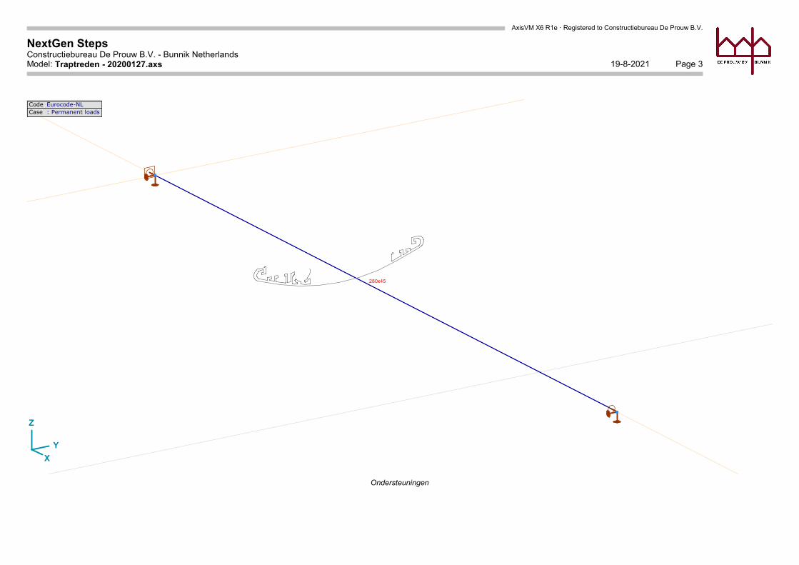
Page 319-8-2021Model: Traptreden - 20200127.axs
X
Y
Z
280x45
Code Eurocode-NLCase : Permanent loads
Ondersteuningen
AxisVM X6 R1e · Registered to Constructiebureau De Prouw B.V.
NextGen StepsConstructiebureau De Prouw B.V. - Bunnik Netherlands
Page 419-8-2021Model: Traptreden - 20200127.axs
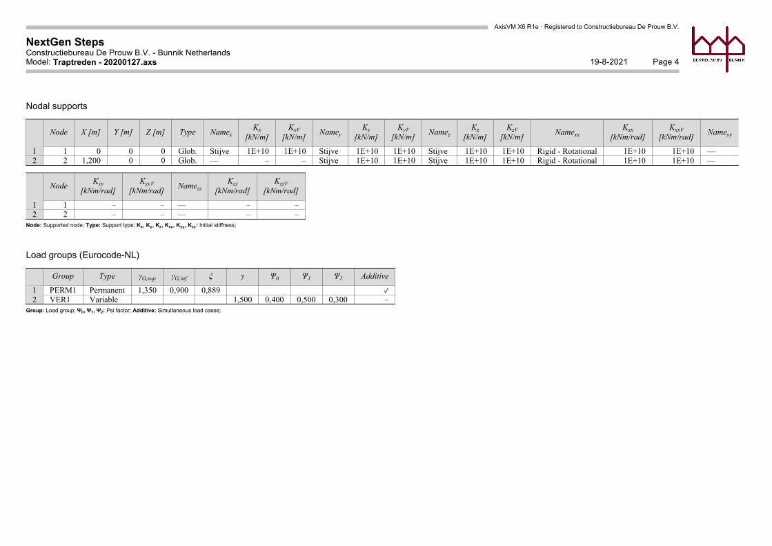
Nodal supports
Node X [m] Y [m] Z [m] Type NamexKx
[kN/m]KxV
[kN/m]Namey
Ky[kN/m]
KyV[kN/m]
NamezKz
[kN/m]KzV
[kN/m]Namexx
Kxx[kNm/rad]
KxxV[kNm/rad]
Nameyy
1 1 0 0 0 Glob. Stijve 1E+10 1E+10 Stijve 1E+10 1E+10 Stijve 1E+10 1E+10 Rigid - Rotational 1E+10 1E+10 —2 2 1,200 0 0 Glob. — – – Stijve 1E+10 1E+10 Stijve 1E+10 1E+10 Rigid - Rotational 1E+10 1E+10 —
NodeKyy
[kNm/rad]KyyV
[kNm/rad]Namezz
Kzz[kNm/rad]
KzzV[kNm/rad]
1 1 – – — – –2 2 – – — – –
Node: Supported node; Type: Support type; Kx, Ky, Kz, Kxx, Kyy, Kzz: Initial stiffness;
Load groups (Eurocode-NL)
Group Type γG,sup γG,inf ξ γ Ψ0 Ψ1 Ψ2 Additive
1 PERM1 Permanent 1,350 0,900 0,889 ✓2 VER1 Variable 1,500 0,400 0,500 0,300 –
Group: Load group; Ψ0, Ψ1, Ψ2: Psi factor; Additive: Simultaneous load cases;
AxisVM X6 R1e · Registered to Constructiebureau De Prouw B.V.
NextGen StepsConstructiebureau De Prouw B.V. - Bunnik Netherlands
Page 519-8-2021Model: Traptreden - 20200127.axs
X
Y
Z
-0,05
Code Eurocode-NLCase : Permanent loads
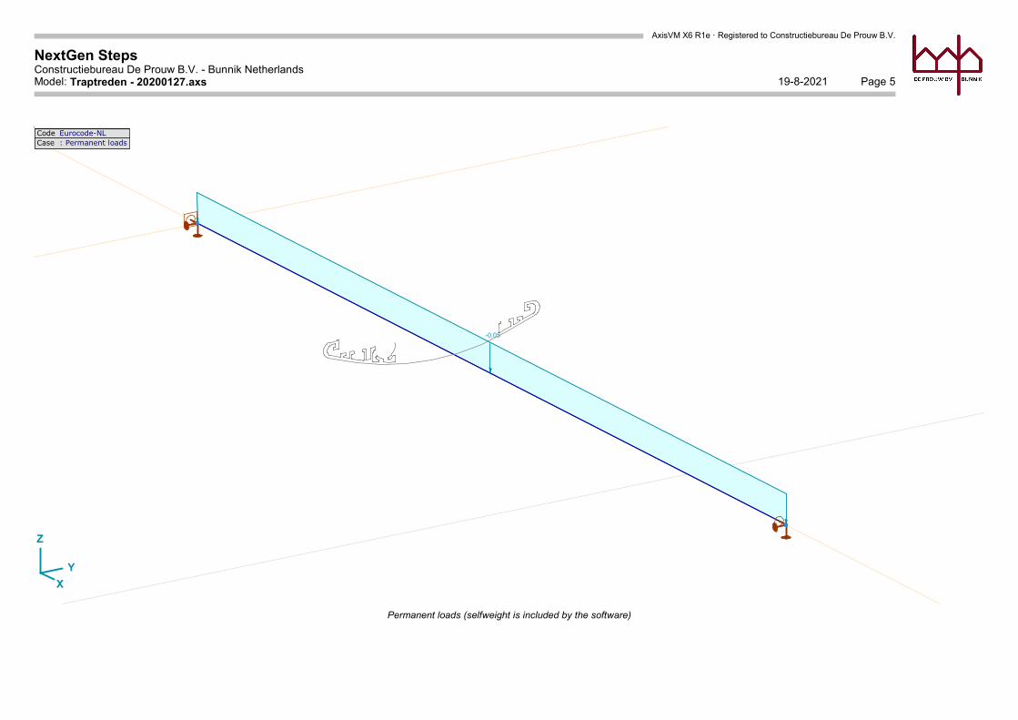
Permanent loads (selfweight is included by the software)
AxisVM X6 R1e · Registered to Constructiebureau De Prouw B.V.
NextGen StepsConstructiebureau De Prouw B.V. - Bunnik Netherlands
Page 619-8-2021Model: Traptreden - 20200127.axs
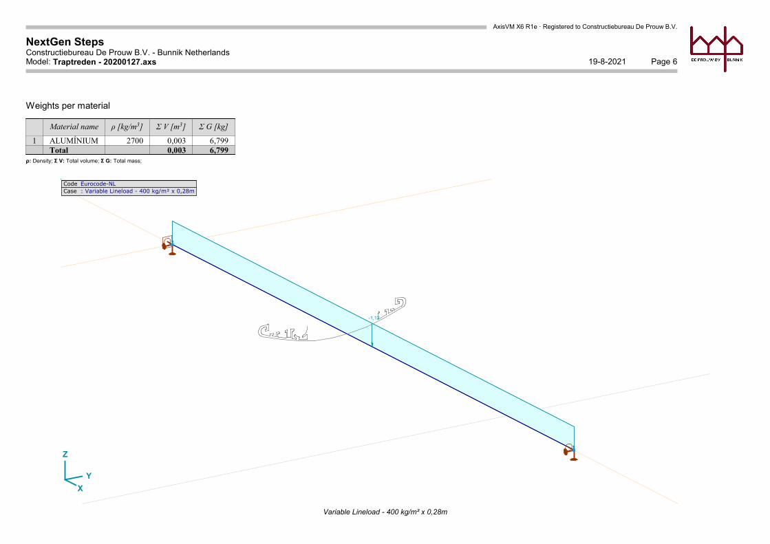
Weights per material
Material name ρ [kg/m3] Σ V [m3] Σ G [kg]
1 ALUMÍNIUM 2700 0,003 6,799Total 0,003 6,799
ρ: Density; Σ V: Total volume; Σ G: Total mass;
X
Y
Z
-1,12
Code Eurocode-NLCase : Variable Lineload - 400 kg/m² x 0,28m
Variable Lineload - 400 kg/m² x 0,28m
AxisVM X6 R1e · Registered to Constructiebureau De Prouw B.V.
NextGen StepsConstructiebureau De Prouw B.V. - Bunnik Netherlands
Page 719-8-2021Model: Traptreden - 20200127.axs
X
Y
Z
-4,0
0
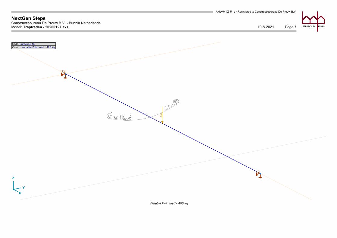
Code Eurocode-NLCase : Variable Pointload - 400 kg
Variable Pointload - 400 kg
AxisVM X6 R1e · Registered to Constructiebureau De Prouw B.V.
NextGen StepsConstructiebureau De Prouw B.V. - Bunnik Netherlands
Page 819-8-2021Model: Traptreden - 20200127.axs
X
Y
Z
-4,0
0
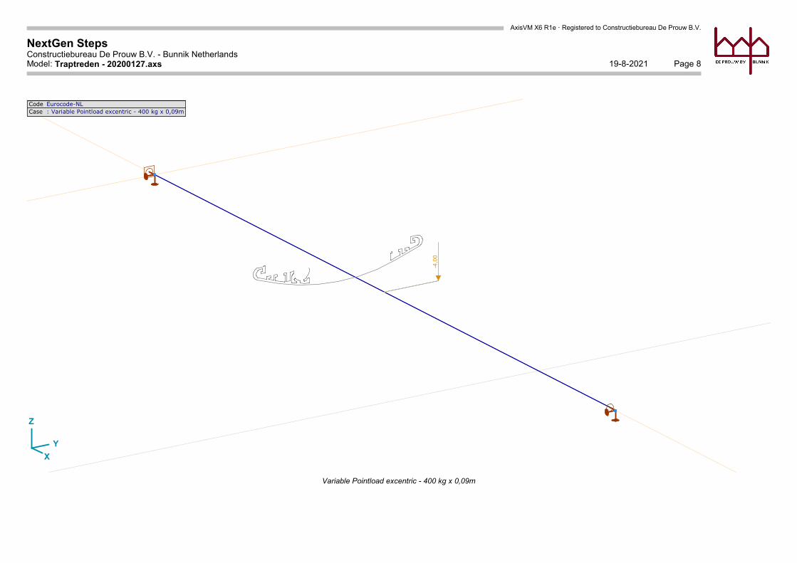
Code Eurocode-NLCase : Variable Pointload excentric - 400 kg x 0,09m
Variable Pointload excentric - 400 kg x 0,09m
AxisVM X6 R1e · Registered to Constructiebureau De Prouw B.V.
NextGen StepsConstructiebureau De Prouw B.V. - Bunnik Netherlands
Page 919-8-2021Model: Traptreden - 20200127.axs
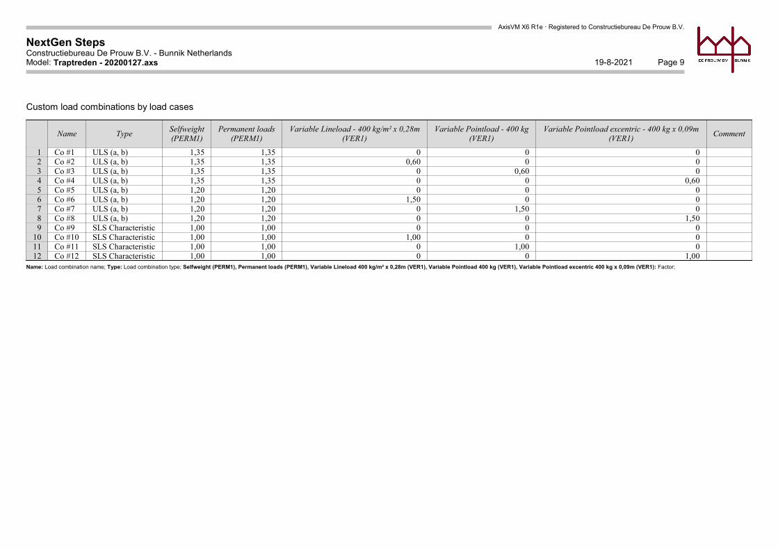
Custom load combinations by load cases
Name TypeSelfweight(PERM1)
Permanent loads(PERM1)
Variable Lineload - 400 kg/m² x 0,28m(VER1)
Variable Pointload - 400 kg(VER1)
Variable Pointload excentric - 400 kg x 0,09m(VER1)
Comment
1 Co #1 ULS (a, b) 1,35 1,35 0 0 02 Co #2 ULS (a, b) 1,35 1,35 0,60 0 03 Co #3 ULS (a, b) 1,35 1,35 0 0,60 04 Co #4 ULS (a, b) 1,35 1,35 0 0 0,605 Co #5 ULS (a, b) 1,20 1,20 0 0 06 Co #6 ULS (a, b) 1,20 1,20 1,50 0 07 Co #7 ULS (a, b) 1,20 1,20 0 1,50 08 Co #8 ULS (a, b) 1,20 1,20 0 0 1,509 Co #9 SLS Characteristic 1,00 1,00 0 0 0
10 Co #10 SLS Characteristic 1,00 1,00 1,00 0 011 Co #11 SLS Characteristic 1,00 1,00 0 1,00 012 Co #12 SLS Characteristic 1,00 1,00 0 0 1,00
Name: Load combination name; Type: Load combination type; Selfweight (PERM1), Permanent loads (PERM1), Variable Lineload 400 kg/m² x 0,28m (VER1), Variable Pointload 400 kg (VER1), Variable Pointload excentric 400 kg x 0,09m (VER1): Factor;
AxisVM X6 R1e · Registered to Constructiebureau De Prouw B.V.
NextGen StepsConstructiebureau De Prouw B.V. - Bunnik Netherlands
Page 1019-8-2021Model: Traptreden - 20200127.axs
X
Y
Z
-1,4
97
-1,12
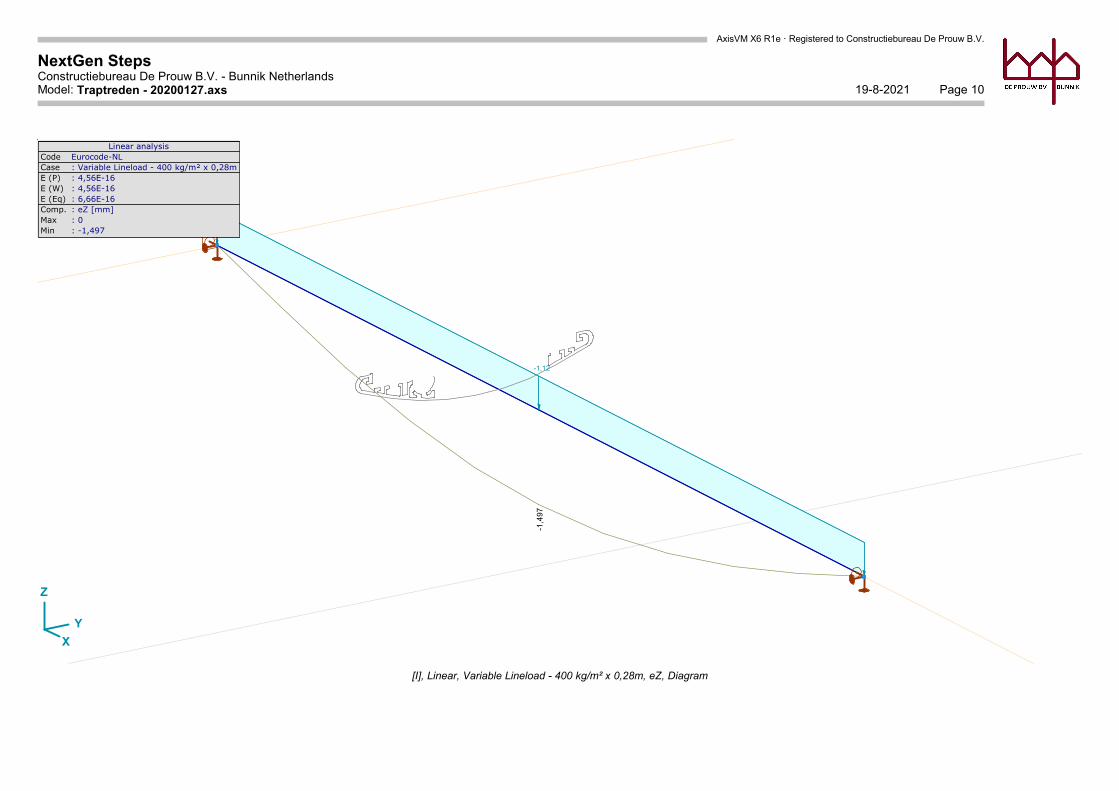
Linear analysisCode Eurocode-NLCase : Variable Lineload - 400 kg/m² x 0,28mE (P) : 4,56E-16E (W) : 4,56E-16E (Eq) : 6,66E-16Comp. : eZ [mm]Max : 0Min : -1,497
[I], Linear, Variable Lineload - 400 kg/m² x 0,28m, eZ, Diagram
AxisVM X6 R1e · Registered to Constructiebureau De Prouw B.V.
NextGen StepsConstructiebureau De Prouw B.V. - Bunnik Netherlands
Page 1119-8-2021Model: Traptreden - 20200127.axs
X
Y
Z
-7,1
27
-4,0
0
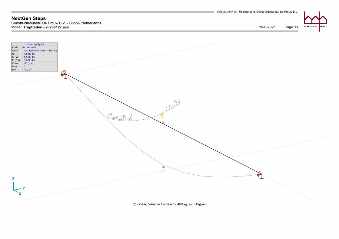
Linear analysisCode Eurocode-NLCase : Variable Pointload - 400 kgE (P) : 4,56E-16E (W) : 4,56E-16E (Eq) : 6,66E-16Comp. : eZ [mm]Max : 0Min : -7,127
[I], Linear, Variable Pointload - 400 kg, eZ, Diagram
AxisVM X6 R1e · Registered to Constructiebureau De Prouw B.V.
NextGen StepsConstructiebureau De Prouw B.V. - Bunnik Netherlands
Page 1219-8-2021Model: Traptreden - 20200127.axs
X
Y
Z
-7,2
70
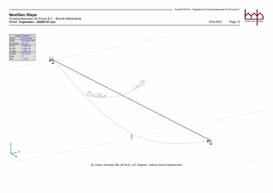
Linear analysisCode Eurocode-NLCase : Envelope MinEnvelope : All SLS E (P) : 4,56E-16E (W) : 4,56E-16E (Eq) : 6,66E-16Comp. : eZ [mm]Max : 0Min : -7,270
[I], Linear, Envelope Min (All SLS ), eZ, Diagram - without torsion displacement

AxisVM X6 R1e · Registered to Constructiebureau De Prouw B.V.
NextGen StepsConstructiebureau De Prouw B.V. - Bunnik Netherlands
Page 1319-8-2021Model: Traptreden - 20200127.axs
X
Y
Z
-3,0
77
3,0
77
0,0
77
-0,0
77
Linear analysisCode Eurocode-NLCase : Envelope Min,MaxEnvelope : All ULS E (P) : 4,56E-16E (W) : 4,56E-16E (Eq) : 6,66E-16Comp. : Vz [kN]Max : 3,077Min : -3,077
Vz[kN]
3,0772,8492,6212,3932,1651,9371,7091,4811,2541,0260,7980,5700,3420,114
-0,114-0,342-0,570-0,798-1,026-1,253-1,481-1,709-1,937-2,165-2,393-2,621-2,849-3,077
[I], Linear, Envelope (All ULS ), Vz, Filled diagram
AxisVM X6 R1e · Registered to Constructiebureau De Prouw B.V.
NextGen StepsConstructiebureau De Prouw B.V. - Bunnik Netherlands
Page 1419-8-2021Model: Traptreden - 20200127.axs
X
Y
Z
-1,8
23
-0,0
23
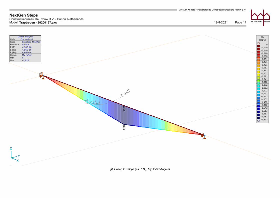
Linear analysisCode Eurocode-NLCase : Envelope Min,MaxEnvelope : All ULS E (P) : 4,56E-16E (W) : 4,56E-16E (Eq) : 6,66E-16Comp. : My [kNm]Max : 0Min : -1,823
My[kNm]
0-0,070-0,140-0,210-0,280-0,351-0,421-0,491-0,561-0,631-0,701-0,771-0,841-0,912-0,982-1,052-1,122-1,192-1,262-1,332-1,402-1,472-1,543-1,613-1,683-1,753-1,823
[I], Linear, Envelope (All ULS ), My, Filled diagram
AxisVM X6 R1e · Registered to Constructiebureau De Prouw B.V.
NextGen StepsConstructiebureau De Prouw B.V. - Bunnik Netherlands
Page 1519-8-2021Model: Traptreden - 20200127.axs
X
Y
Z
-0,2
70
0,2
70
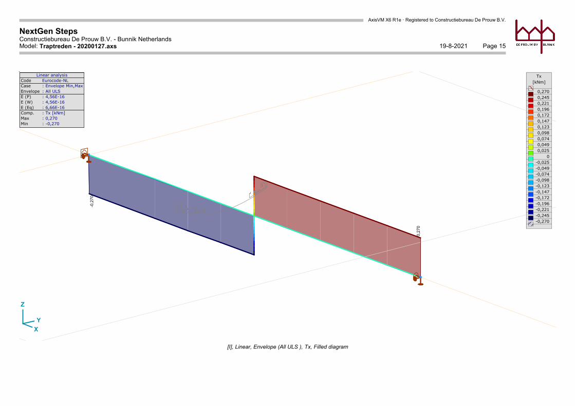
Linear analysisCode Eurocode-NLCase : Envelope Min,MaxEnvelope : All ULS E (P) : 4,56E-16E (W) : 4,56E-16E (Eq) : 6,66E-16Comp. : Tx [kNm]Max : 0,270Min : -0,270
Tx[kNm]
0,2700,2450,2210,1960,1720,1470,1230,0980,0740,0490,025
0-0,025-0,049-0,074-0,098-0,123-0,147-0,172-0,196-0,221-0,245-0,270
[I], Linear, Envelope (All ULS ), Tx, Filled diagram
AxisVM X6 R1e · Registered to Constructiebureau De Prouw B.V.
NextGen StepsConstructiebureau De Prouw B.V. - Bunnik Netherlands
Page 1619-8-2021Model: Traptreden - 20200127.axs
X
Y
Z
-3,0
77
-3,07
7
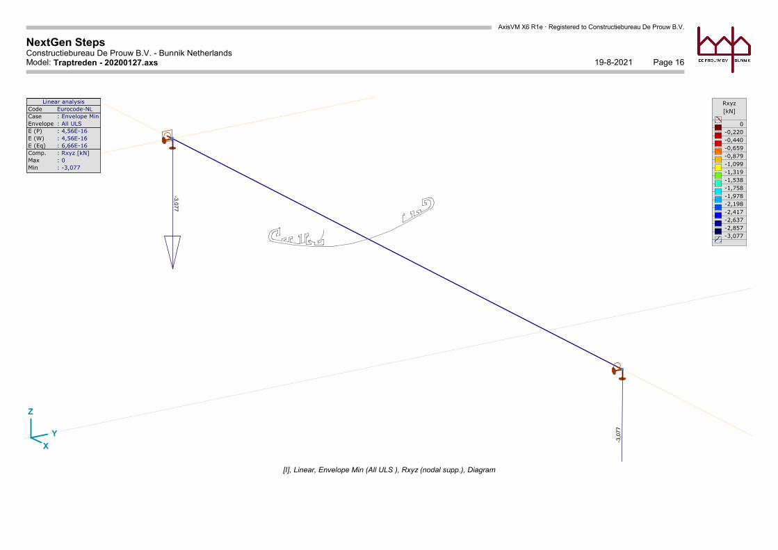
Linear analysisCode Eurocode-NLCase : Envelope MinEnvelope : All ULS E (P) : 4,56E-16E (W) : 4,56E-16E (Eq) : 6,66E-16Comp. : Rxyz [kN]Max : 0Min : -3,077
Rxyz[kN]
0-0,220-0,440-0,659-0,879-1,099-1,319-1,538-1,758-1,978-2,198-2,417-2,637-2,857-3,077
[I], Linear, Envelope Min (All ULS ), Rxyz (nodal supp.), Diagram
AxisVM X6 R1e · Registered to Constructiebureau De Prouw B.V.
NextGen StepsConstructiebureau De Prouw B.V. - Bunnik Netherlands
Page 1719-8-2021Model: Traptreden - 20200127.axs
X
Y
Z
16
5,8
5
38
,32
38
,32
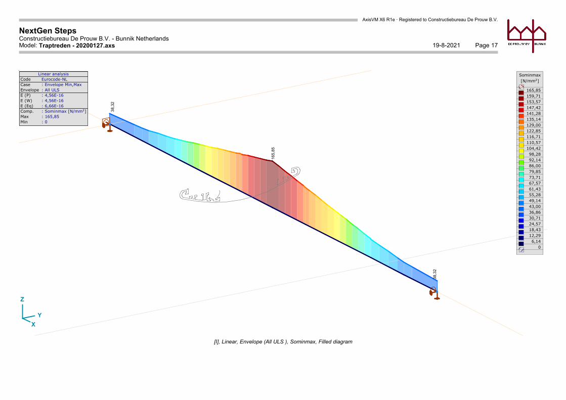
Linear analysisCode Eurocode-NLCase : Envelope Min,MaxEnvelope : All ULS E (P) : 4,56E-16E (W) : 4,56E-16E (Eq) : 6,66E-16Comp. : Sominmax [N/mm2]Max : 165,85Min : 0
Sominmax[N/mm2]
165,85159,71153,57147,42141,28135,14129,00122,85116,71110,57104,4298,2892,1486,0079,8573,7167,5761,4355,2849,1443,0036,8630,7124,5718,4312,296,14
0
[I], Linear, Envelope (All ULS ), Sominmax, Filled diagram

AxisVM X6 R1e · Registered to Constructiebureau De Prouw B.V.
NextGen StepsConstructiebureau De Prouw B.V. - Bunnik Netherlands
Page 1819-8-2021Model: Traptreden - 20200127.axs
Sminmax [N/mm2]
x
-165,84
124,61
Vminmax [N/mm2]
x
22,12 22,13 22,12
Sominmax [N/mm2]
x
38,32
165,85
38,32
Linear - Envelope Min,Max
x[m]
S.p. Sx min Sx max Vmin Vmax Somin Somax1 2 3 4 5
MinMax
VymeanVzmean [N/mm2]
0,600
0 0 0 0 0 0-165,84 -2,10 0 1,02 2,10 165,85
-58,56 -0,74 0 3,05 0,74 58,80-58,56 -0,74 0 22,13 0,74 69,99
1,57 124,61 0 21,17 1,57 129,89
-165,84 0 0124,61 22,13 165,85
0 0-1,43 0
Material ALUMÍNIUME [N/mm2] 70000
Cross-section 280x45Ax [mm2] 2098,49Ay [mm2] 1032,83Az [mm2] 112,68Ix [mm4] 320065,8Iy [mm4] 288626,9Iz [mm4] 1,4E+07
Cross-section location:
x [m] =
Total length: 1,200 m
[1]
1 2
0,600 m
1
23 4
5G
S
Sminmax [N/mm2]
00
-165,84
-2,10
-58,56
-0,74
-58,56
-0,741,57
124,61
Vminmax [N/mm2]
00
0 1,020
3,050
22,13
0
21,17
Sominmax [N/mm2]
00
2,10
165,85
0,74
58,80
0,74
69,99
1,57
129,89
[I], Linear, Envelope (All ULS ), Beam stresses, Beam 1, [Pos.: 0,600m;]