MEB, MEJ, EP-SH-N, P-SH-N(2), MaxION, MSB-375, SS, QMC. · Staven 97.52.03.90.10 5 08/08 MaxION...
22
Staven 97.52.03.90.10 08/08 MEB, MEJ, EP-SH-N, P-SH-N(2), MaxION, MSB-375, SS, QMC. Ionisatiestaven Ionensprühstäbe Anti-Static Bars Barres Ionisantes Gebruikershandleiding NL Pagina 3 Bedienungsanleitung D Seite 8 User’s Manual E Page 13 Notice d’utilisation F Page 18 SIMCO (Nederland) B.V. Postbus 71 NL-7240 AB Lochem Telefoon + 31-(0)573-288333 Telefax + 31-(0)573-257319 E-mail [email protected] Internet http://www.simco.nl Traderegister Apeldoorn No. 08046136
Transcript of MEB, MEJ, EP-SH-N, P-SH-N(2), MaxION, MSB-375, SS, QMC. · Staven 97.52.03.90.10 5 08/08 MaxION...
Staven 97.52.03.90.10 08/08
MEB, MEJ, EP-SH-N, P-SH-N(2), MaxION, MSB-375, SS, QMC.
Ionisatiestaven Ionensprühstäbe Anti-Static Bars Barres Ionisantes Gebruikershandleiding NL Pagina 3 Bedienungsanleitung D Seite 8 User’s Manual E Page 13 Notice d’utilisation F Page 18
SIMCO (Nederland) B.V. Postbus 71 NL-7240 AB Lochem Telefoon + 31-(0)573-288333 Telefax + 31-(0)573-257319 E-mail [email protected] Internet http://www.simco.nl Traderegister Apeldoorn No. 08046136
Staven 97.52.03.90.10 2 08/08
INHOUDSOPGAVE Pagina 1. Inleiding 3 2. Veiligheid 3 3. Toepassing en werking 3 4. Technische specificaties 4 5. Installatie 4 6. Ingebruikneming 6 7. Controle op de werking 6 8. Onderhoud 6 9. Storingen 7 10. Reparaties 7 11. Afdanken 7 CONTENTS Page 1. Introduction 13 2. Safety 13 3. Use and Operation 13 4. Technical Specifications 14 5. Installation 14 6. Putting into use 16 7. Functional check 16 8. Maintenance 16 9. Faults 17 10. Repair 17 11. Disposal 17
INHALT Seite 1. Einführung 8 2. Sicherheit 8 3. Einsatz und Funktionsweise 8 4. Technische Angaben 9 5. Installation 9 6. Inbetriebnahme 11 7. Funktionsprüfung 11 8. Wartung 11 9. Störungen 12 10. Reparatur 12 11. Entsorgung 12 SOMMAIRE Page 1. Introduction 18 2. Sécurité 18 3. Application et fonctionnement 18 4. Spécification techniques 19 5. Installation 19 6. Mise en service 21 7. Contrôle du fonctionnement 21 8. Entretien 21 9. Pannes 22 10. Réparation 22 11. Mise au rebut 22
Staven 97.52.03.90.10 3 08/08
GEBRUIKERSHANDLEIDING IONISATIESTAVEN 1. Inleiding Lees deze handleiding geheel door voordat u dit product installeert en in gebruik neemt. Instructies in deze handleiding dienen te worden opgevolgd om een goede werking van het product te waarborgen en om aanspraak te kunnen maken op garantie De garantiebepalingen zijn omschreven in de Algemene Verkoopvoorwaarden van SIMCO (Nederland) B.V. Deze handleiding is van toepassing voor de schokvrije ionisatiestaven met de typeaandui-dingen: MEB, MEJ, EP-SH, P-SH-N(2), MaxION en MSB-375 en de niet schokvrije ionisatiestaven: Super Service (SS) en QMC. 2. Veiligheid − De SIMCO ionisatiestaven zijn uitsluitend bestemd voor het neutraliseren van
statische elektriciteit. − Niet schokvrije staven niet monteren in een omgeving met licht ontvlambare stoffen. − Zorg voor een goede aarding van de apparatuur.
Aarding is nodig voor een goede werking en voorkomt, bij aanraking, elektrische schokken. − Elektrische installatie, onderhoud en reparatie dient te geschieden door een elektrotechnisch
vakbekwaam persoon. − Raak van de staven SS en QMC geen onder spanning staande punten aan:
Hierdoor krijgt u een onaangename elektrische schok − Bij werkzaamheden aan de apparatuur: Apparatuur spanningsloos maken. − Indien zonder schriftelijke goedkeuring vooraf wijzigingen, aanpassingen, etc. zijn
aangebracht verliest het apparaat zijn garantie. 3. Toepassing en werking De SIMCO ionisatiestaven zijn bedoeld om statische lading van vellen, banen en andere vlakke materialen te neutraliseren. De ionisatiestaven kunnen alleen worden gebruikt in combinatie met een SIMCO hoogspanningsvoeding. De hoogspanning wekt aan de punten van de ionisatiestaaf een elektrisch veld op, waardoor de luchtmoleculen rondom de ionisatiepunten worden omgezet in positieve en negatieve ionen. Wanneer een elektrostatisch geladen materiaal in de nabijheid van de ionisatiepunten komt vindt er een uitwisseling van elektronen plaats totdat het materiaal neutraal is. De punten van de schokvrije ionisatiestaven, MEB, MEJ, EP-SH-N, P-SH-N(2), MaxION en MSB-375, zijn capacitief met de hoogspanning gekoppeld en daardoor aanrakingsveilig. De punten van de niet schokvrije ionisatiestaven SS en QMC zijn direct gekoppeld met de hoogspanning en geven, bij aanraking, een elektrische schok.
Staven 97.52.03.90.10 4 08/08
4. Technische specificaties Schokvrije ionisatiestaven MEB / MEJ EP-SH-N P-SH-N P-SH-N2 MaxION MSB-375 Werkspanning: ca. 7 kV ca. 7 kV ca. 7 kV ca. 7 kV 5 kV 5 kV Max. stroom 20 μA 20 μA 20 μA 20 μA 30 μA 10 μA Temperatuur max.: 55 °C 55 °C 55 °C 55 °C 70 °C 50 °C Werkafstand max.: 30 mm 150 mm 600 mm 150 mm 400 mm 50 mm Werkafstand gebruikelijk: 25 mm 50 mm 50 mm 50 mm 50-80 mm 20 mm Niet schokvrije ionisatiestaven SS / QMC Werkspanning: 4 kV Stroom max. *1: 3 mA Temperatuur max.: 55 °C *2 Werkafstand max.: 30 mm Werkafstand gewoonlijk: 25 mm *1 Begrensd door bijbehorend voedingsapparaat. *2 Optie: SS / QMC ionisatiestaven tot 150 °C mogelijk. Gebruiksomstandigheden: Industrieel 5. Installatie 5.1. Controle − Controleer of de ionisatiestaaf onbeschadigd en in de juiste uitvoering ontvangen is. − Controleer of de pakbongegevens overeenkomen met de gegevens op het ontvangen
product. Bij problemen en/of onduidelijkheden: Neem contact op met SIMCO of met de agent in uw regio. 5.2. Installatie 5.2.1. Overzicht Monteer de ionisatiestaaf juist voor de plaats waar statische elektriciteit problemen veroorzaakt. Daar waar het materiaal wordt geneutraliseerd dient het een ondergrond van lucht te hebben. De juiste afstand van de ionisatiestaaf tot het materiaal dient proefondervindelijk te worden vastgesteld (zie technische specificaties). De punten van de ionisatiestaaf mogen niet worden afgedekt. Ionisatiestaven EP-SH-N en P-SH-N(2) aan de achterzijde niet afdekken, een vrije doorgang van lucht is belangrijk voor een goede werking.
Staven 97.52.03.90.10 5 08/08
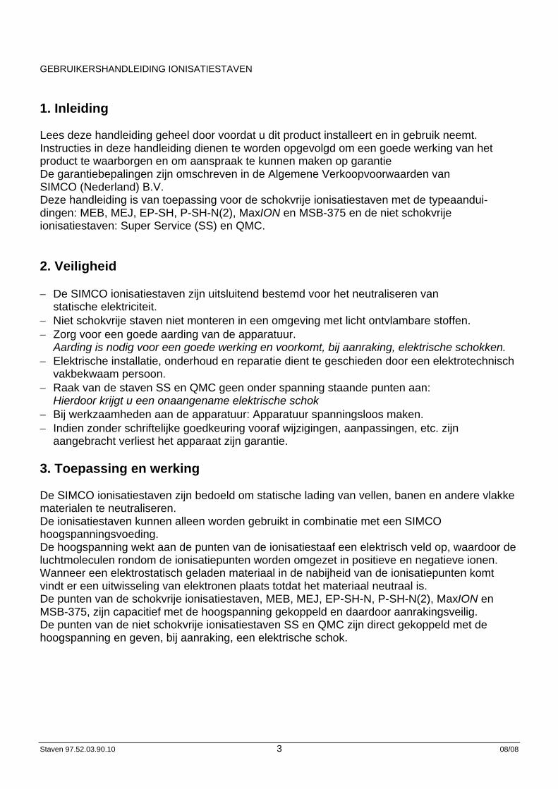
MaxION Voor een goede werking moet de staaf aan de zijkanten min. 50 mm en aan de achterzijde min. 10 mm vrij zijn van metaal.
Waarschuwing: − MaxION: De montageschroeven in de glijmoeren handvast aandraaien. Te vast
aandraaien van de schroeven beschadigd het kunststofprofiel. − Niet afgeschermde HS kabels niet langs scherpe metalen delen leggen. − HS kabels niet knikken of in scherpe bochten verleggen. − Bij aansluiten van niet metaalafgeschermde HS kabels op een LB- voedingsapparaat
mogen de HS kabels, aangesloten op de verschillende trafo's, niet gekruist zijn en dienen deze HS kabels minimaal 1 cm van elkaar te zijn verlegd. Niet nakomen van deze regel heeft nadelige invloeden op de HS kabel.
5.2.2. Montage − Monteer de ionisatiestaaf met de punten in de richting en op de aanbevolen afstand, van het
te ontladen materiaal. Hierbij mogen de punten niet naar metaal kijken − Gebruik de meegeleverde montage materialen. − Zorg voor een goede aarding van de apparatuur.
(De MaxION wordt via de afgeschermde kabel geaard via het voedingsapparaat) − Monteer de HS kabel met de meegeleverde montageklemmen langs het machineframe. − Sluit de HS kabel aan op het voedingsapparaat,
zie handleiding voedingsapparaat.
Let op de juiste uitgangsspanning van het voedingsapparaat.
Staven 97.52.03.90.10 6 08/08
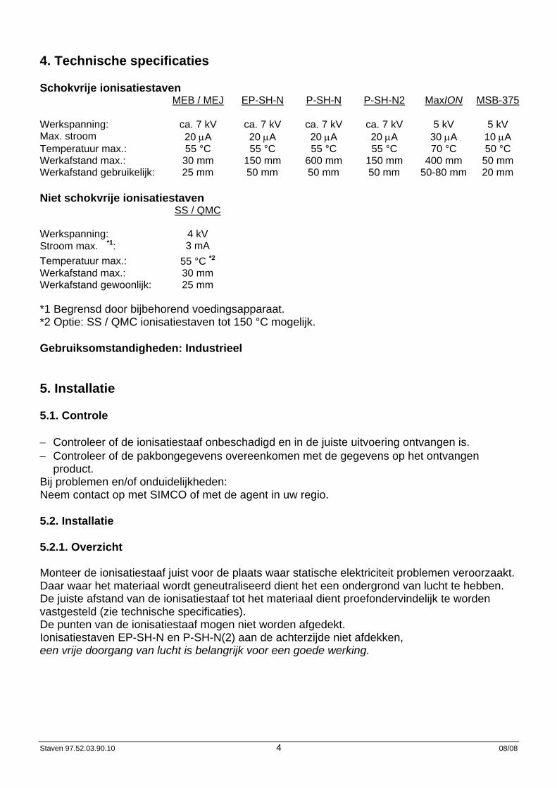
5.3. Inkorten hoogspanningskabel. De metalen afscherming mag door de klant niet worden ingekort. Het eventueel inkorten van de (blauwe) hoogspanningskabel, toegepast in de staven MEB, MEJ, EP-SH-N, P-SH-N(2), dient te gebeuren als aangegeven in onderstaande schets.
Blauwe PVC laag verwijderen Afgeschermde HV - kabel
Waarschuwing: transparante PE isolatie niet beschadigen! De hoogspanningskabel van de staven MaxION, QMC en SS kunnen op een gebruikelijke wijze worden afgestript. 6. Ingebruikneming Door het inschakelen van het voedingsapparaat wordt de ionisatiestaaf in werking gesteld. 7. Controle op de werking Met een SIMCO staaftester kan worden gecontroleerd of de hoogspanning op de punten aanwezig is. Voor het bepalen van de efficiency van de ionisatiestaaf dient een veldsterktemeter te worden gebruikt. Meet de lading op het materiaal voor en na het passeren van de ionisatiestaaf. De gemeten lading dient na het passeren van de ionisatiestaaf verdwenen te zijn. 8. Onderhoud
Waarschuwing: − Bij werkzaamheden aan de apparatuur: apparatuur spanningsloos maken.
Let op: − Ionisatiepunten niet beschadigen. − Houdt de ionisatiestaaf schoon. − Bij vervuiling: ionisatiestaaf reinigen met een harde niet metalen borstel.
(Borstel: Simco artikelnr. 2000430001) Bij sterke vervuiling: ionisatiestaaf reinigen met isopropyl alcohol of met Veconova 10 industriële reiniger (www.eco-nova.nl) (niet voor ionisatiestaaf MSB).
− Laat de ionisatiestaaf geheel drogen, voor het opnieuw in werking stellen.
47 +/- 2
77
Staven 97.52.03.90.10 7 08/08
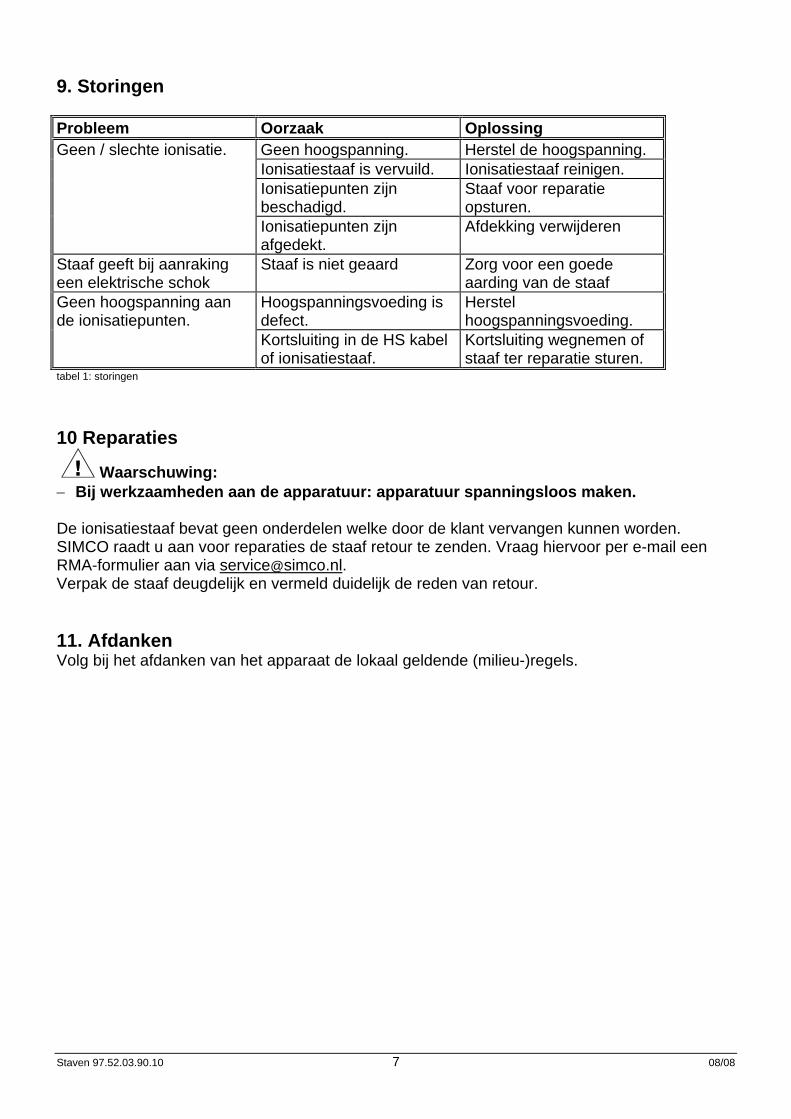
9. Storingen Probleem Oorzaak Oplossing Geen / slechte ionisatie. Geen hoogspanning. Herstel de hoogspanning. Ionisatiestaaf is vervuild. Ionisatiestaaf reinigen. Ionisatiepunten zijn
beschadigd. Staaf voor reparatie opsturen.
Ionisatiepunten zijn afgedekt.
Afdekking verwijderen
Staaf geeft bij aanraking een elektrische schok
Staaf is niet geaard Zorg voor een goede aarding van de staaf
Geen hoogspanning aan de ionisatiepunten.
Hoogspanningsvoeding is defect.
Herstel hoogspanningsvoeding.
Kortsluiting in de HS kabel of ionisatiestaaf.
Kortsluiting wegnemen of staaf ter reparatie sturen.
tabel 1: storingen
10 Reparaties
Waarschuwing: − Bij werkzaamheden aan de apparatuur: apparatuur spanningsloos maken. De ionisatiestaaf bevat geen onderdelen welke door de klant vervangen kunnen worden. SIMCO raadt u aan voor reparaties de staaf retour te zenden. Vraag hiervoor per e-mail een RMA-formulier aan via [email protected]. Verpak de staaf deugdelijk en vermeld duidelijk de reden van retour.
11. Afdanken Volg bij het afdanken van het apparaat de lokaal geldende (milieu-)regels.
Staven 97.52.03.90.10 8 08/08
BEDIENUNGSANLEITUNG FÜR IONENSPRÜHSTÄBE 1. Einführung Lesen Sie diese Anleitung vor der Installation und Inbetriebnahme dieses Produktes vollständig durch. Befolgen Sie die Anweisungen in dieser Anleitung, um eine richtige Funktionsweise des Produktes sicherzustellen und irgendwelche Garantieansprüche geltend machen zu können. Die Garantiebedingungen sind in den Allgemeinen Verkaufsbedingungen von SIMCO (Nederland) B.V. festgelegt. Diese Anleitung trifft auf die berührungssicheren mit der Typenbezeichnung MEB, MEJ, EP-SH-N, P-SH-N(2), MaxION oder MSB-375 und nicht berührungssicheren Ionensprühstäbe Super Service (SS) und QMC zu. 2. Sicherheit − Die SIMCO-Ionensprühstäbe wurden ausschließlich zur Beseitigung von statischer
Elektrizität entwickelt. − Nicht berührungssichere Stäbe sind nicht in einer Umgebung mit feuergefährlichen Stoffen
einzusetzen. − Elektrische Anschluß-, Wartungs- und Reparaturarbeiten sind von elektrotechnisch
fachkundigem Personal durchzuführen. − Bei der Durchführung von Arbeiten am Gerät: das Gerät spannungslos machen. − Wenn ohne vorhergehende schriftliche Genehmigung Änderungen, Anpassungen usw.
vorgenommen wurden, können keine Garantieansprüche geltend gemacht werden. − Sorgen Sie für eine richtige Geräte-Erdung.
Erdung ist für eine einwandfreie Funktionsweise erforderlich und verhindert Stromschläge bei Berührung.
− Berühren Sie an den Stäben SS und QMC keine spannungsführenden Spitzen.: Sie werden sonst einen unangenehmen Stromschlag empfinden.
3. Einsatz und Funktionsweise Die SIMCO-Ionensprühstäbe wurden dazu ausgelegt, statische Aufladung von Bögen, Bahnen und sonstigen Flachmaterialien zu beseitigen. Die Ionensprühstäbe lassen sich nur in Verbindung mit einem SIMCO- Hochspannungs-Netzteil verwenden. Die Hochspannung erzeugt an den Spitzen des Ionensprühstabs ein elektrisches Feld, wodurch die Luftmoleküle rund um die Ionensprühspitzen in positive und negative Ionen zerlegt werden. Wenn elektrostatisch geladenes Material in die Nähe der Ionensprühspitzen gelangt, findet ein Elektronenaustausch statt, bis das Material neutral ist. Die Spitzen der berührungssicheren Ionensprühstäbe MEB, MEJ, EP-SH-N, P-SH-N(2), MaxION en MSB-375, sind kapazitiv mit der Hochspannung verbunden und somit berührungssicher. Die Spitzen der nicht berührungssicheren Ionensprühstäbe SS en QMC sind direkt mit der Hochspannung verbunden und bei deren Berührung empfinden Sie einen Stromschlag.
Staven 97.52.03.90.10 9 08/08
4. Technische Angaben Berührungssichere Ionensprühstäbe MEB / MEJ EP-SH-N P-SH-N P-SH-N2 MaxION MSB-375 Betriebsspannung: ca. 7 kV ca. 7 kV ca. 7 kV ca. 7 kV ca. 5 kV ca. 5 kV Max. Ionenstromstärke: 20 μA 20 μA 20 μA 20 μA 30 μA 10 μA Max. Temperatur: 55 °C. 55 °C. 55 °C. 55 °C. 70 °C. 50 °C. Max. Betriebs- entfernung:
30 mm
150 mm
600 mm
150 mm
400 mm
50 mm
Betriebsentfernung gewöhnlich:
25 mm
50 mm
50 mm
50 mm
50-80 mm
20 mm
Nicht berührungssichere Ionensprühstäbe SS / QMC Betriebsspannung: 4 kV Max. Stromstärke*1: 3 mA Max. Temperatur: 55°C.*2 Max. Betriebs-entfernung: 30 mm Betriebsentfernung gewöhnlich:
25 mm
*1 Durch zugehöriges Netzteil begrenzt. *2 Option: SS / QMC-Ionensprühstäbe bis 150 °C möglich. Betriebsbedingungen: Industrie-Einsatz 5. Installation 5.1. Kontrolle − Prüfen Sie, ob der Ionensprühstab unbeschädigt ist und ob Sie die richtige Ausführung
erhalten haben. − Prüfen Sie, ob die Angaben auf dem Packzettel mit den am Produkt angezeigten Daten
übereinstimmen. Bei irgendwelchen Problemen und/oder Unklarheiten: können Sie sich mit SIMCO oder Ihrem Regionalagenten in Verbindung setzen. 5.2. Installation 5.2.1. Überblick Montieren Sie den Ionensprühstab genau vor der Stelle, wo die statische Elektrizität Schwierigkeiten verursacht. Dort wo das Material neutralisiert wird, ist ein Untergrund aus Luft erforderlich. Die richtige Entfernung zwischen Ionensprühstab und Material ist erfahrungsgemäß zu ermitteln (siehe die technischen Angaben). Die Spitzen des Ionensprühstabs dürfen nicht abgedeckt sein. Decken Sie die EP-SH-N und P-SH-N(2) Ionensprühstäbe auf der Rückseite nicht ab. ein freier Luftdurchgang ist wichtig für eine gute Funktionsweise.
Staven 97.52.03.90.10 10 08/08
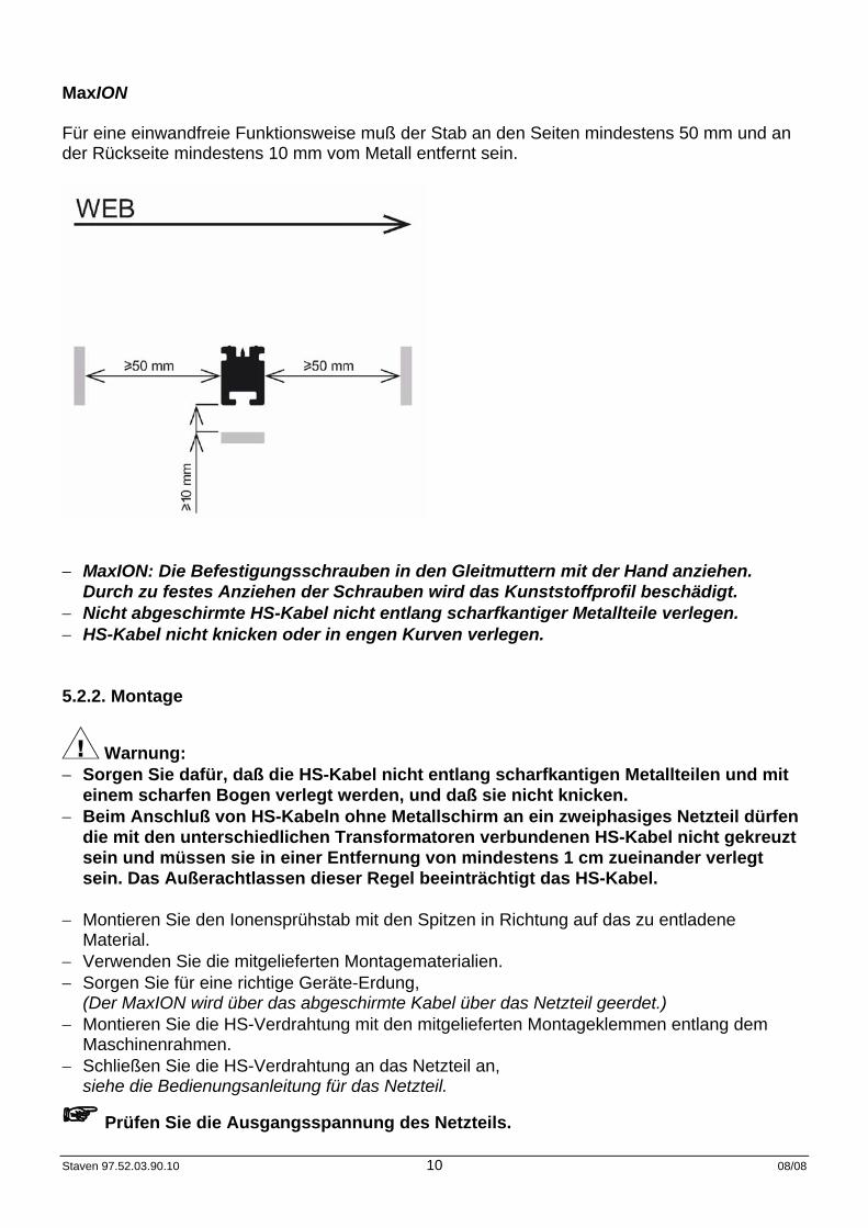
MaxION Für eine einwandfreie Funktionsweise muß der Stab an den Seiten mindestens 50 mm und an der Rückseite mindestens 10 mm vom Metall entfernt sein.
− MaxION: Die Befestigungsschrauben in den Gleitmuttern mit der Hand anziehen.
Durch zu festes Anziehen der Schrauben wird das Kunststoffprofil beschädigt. − Nicht abgeschirmte HS-Kabel nicht entlang scharfkantiger Metallteile verlegen. − HS-Kabel nicht knicken oder in engen Kurven verlegen. 5.2.2. Montage
Warnung: − Sorgen Sie dafür, daß die HS-Kabel nicht entlang scharfkantigen Metallteilen und mit
einem scharfen Bogen verlegt werden, und daß sie nicht knicken. − Beim Anschluß von HS-Kabeln ohne Metallschirm an ein zweiphasiges Netzteil dürfen
die mit den unterschiedlichen Transformatoren verbundenen HS-Kabel nicht gekreuzt sein und müssen sie in einer Entfernung von mindestens 1 cm zueinander verlegt sein. Das Außerachtlassen dieser Regel beeinträchtigt das HS-Kabel.
− Montieren Sie den Ionensprühstab mit den Spitzen in Richtung auf das zu entladene
Material. − Verwenden Sie die mitgelieferten Montagematerialien. − Sorgen Sie für eine richtige Geräte-Erdung,
(Der MaxION wird über das abgeschirmte Kabel über das Netzteil geerdet.) − Montieren Sie die HS-Verdrahtung mit den mitgelieferten Montageklemmen entlang dem
Maschinenrahmen. − Schließen Sie die HS-Verdrahtung an das Netzteil an,
siehe die Bedienungsanleitung für das Netzteil.
Prüfen Sie die Ausgangsspannung des Netzteils.
Staven 97.52.03.90.10 11 08/08
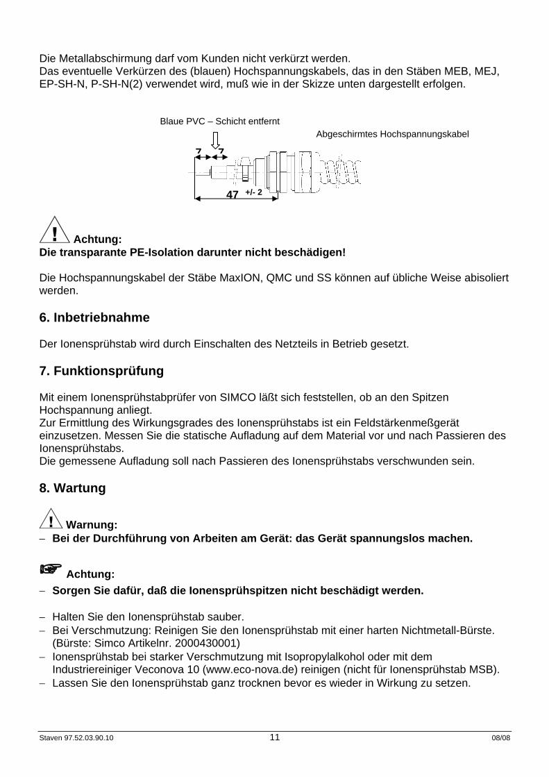
Die Metallabschirmung darf vom Kunden nicht verkürzt werden. Das eventuelle Verkürzen des (blauen) Hochspannungskabels, das in den Stäben MEB, MEJ, EP-SH-N, P-SH-N(2) verwendet wird, muß wie in der Skizze unten dargestellt erfolgen.
Blaue PVC – Schicht entfernt Abgeschirmtes Hochspannungskabel
Achtung: Die transparante PE-Isolation darunter nicht beschädigen! Die Hochspannungskabel der Stäbe MaxION, QMC und SS können auf übliche Weise abisoliert werden. 6. Inbetriebnahme Der Ionensprühstab wird durch Einschalten des Netzteils in Betrieb gesetzt. 7. Funktionsprüfung Mit einem Ionensprühstabprüfer von SIMCO läßt sich feststellen, ob an den Spitzen Hochspannung anliegt. Zur Ermittlung des Wirkungsgrades des Ionensprühstabs ist ein Feldstärkenmeßgerät einzusetzen. Messen Sie die statische Aufladung auf dem Material vor und nach Passieren des Ionensprühstabs. Die gemessene Aufladung soll nach Passieren des Ionensprühstabs verschwunden sein. 8. Wartung
Warnung: − Bei der Durchführung von Arbeiten am Gerät: das Gerät spannungslos machen.
Achtung: − Sorgen Sie dafür, daß die Ionensprühspitzen nicht beschädigt werden. − Halten Sie den Ionensprühstab sauber. − Bei Verschmutzung: Reinigen Sie den Ionensprühstab mit einer harten Nichtmetall-Bürste.
(Bürste: Simco Artikelnr. 2000430001) − Ionensprühstab bei starker Verschmutzung mit Isopropylalkohol oder mit dem
Industriereiniger Veconova 10 (www.eco-nova.de) reinigen (nicht für Ionensprühstab MSB). − Lassen Sie den Ionensprühstab ganz trocknen bevor es wieder in Wirkung zu setzen.
47 +/- 2
77
Staven 97.52.03.90.10 12 08/08
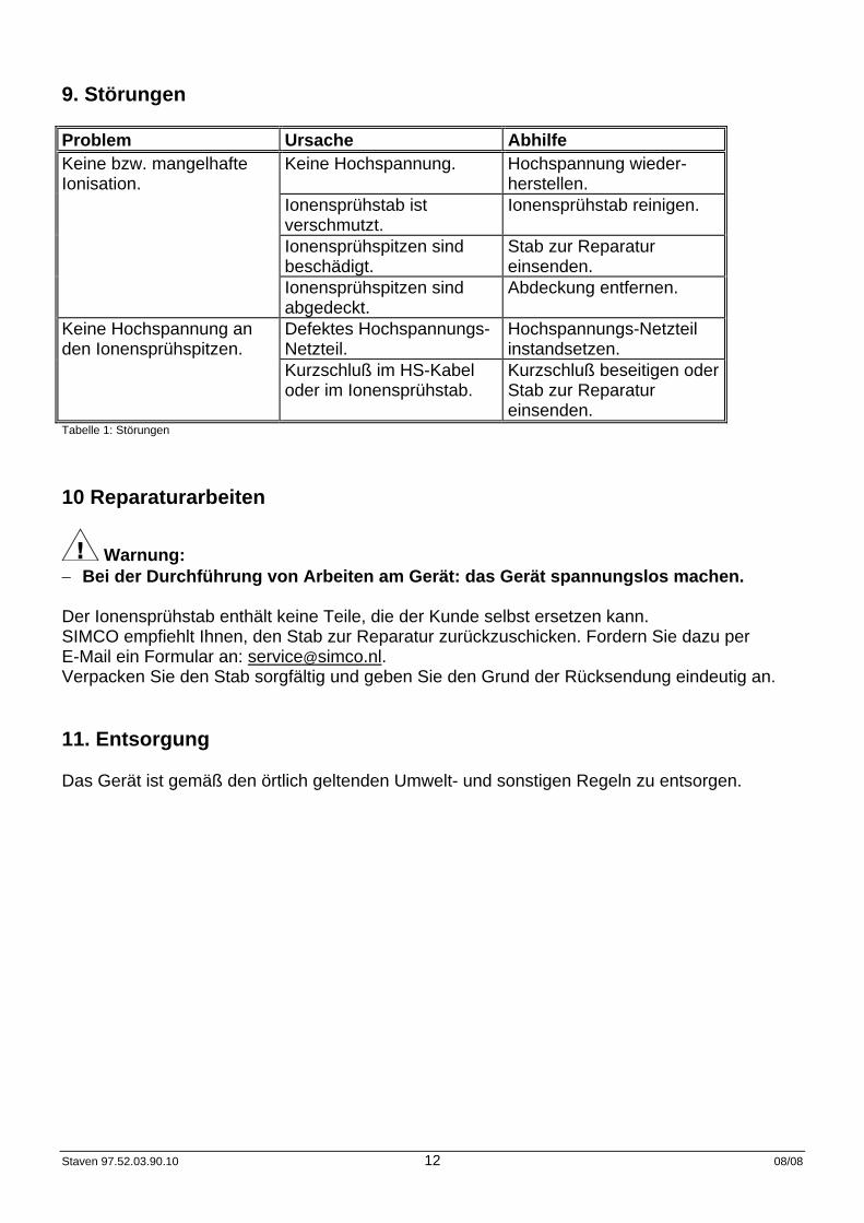
9. Störungen Problem Ursache Abhilfe Keine bzw. mangelhafte Ionisation.
Keine Hochspannung. Hochspannung wieder-herstellen.
Ionensprühstab ist verschmutzt.
Ionensprühstab reinigen.
Ionensprühspitzen sind beschädigt.
Stab zur Reparatur einsenden.
Ionensprühspitzen sind abgedeckt.
Abdeckung entfernen.
Keine Hochspannung an den Ionensprühspitzen.
Defektes Hochspannungs-Netzteil.
Hochspannungs-Netzteil instandsetzen.
Kurzschluß im HS-Kabel oder im Ionensprühstab.
Kurzschluß beseitigen oder Stab zur Reparatur einsenden.
Tabelle 1: Störungen 10 Reparaturarbeiten
Warnung: − Bei der Durchführung von Arbeiten am Gerät: das Gerät spannungslos machen. Der Ionensprühstab enthält keine Teile, die der Kunde selbst ersetzen kann. SIMCO empfiehlt Ihnen, den Stab zur Reparatur zurückzuschicken. Fordern Sie dazu per E-Mail ein Formular an: [email protected]. Verpacken Sie den Stab sorgfältig und geben Sie den Grund der Rücksendung eindeutig an. 11. Entsorgung Das Gerät ist gemäß den örtlich geltenden Umwelt- und sonstigen Regeln zu entsorgen.
Staven 97.52.03.90.10 13 08/08
USER'S MANUAL FOR ANTI-STATIC BARS 1. Introduction Read this manual completely before you install and put this product into use. Follow the instructions set out in this manual to ensure proper operation of the product and to be able to invoke guarantee. The guarantee terms are stated in the General Conditions for the Sale and Delivery of Products and/or Performance of Activities by SIMCO (Nederland) B.V. This manual applies to the shockproof anti-static bars with a type indication MEB, MEJ, EP-SH-N, P-SH-N(2), MaxION and MSB-375 and the non-shockproof anti-static bars SS and QMC. 2. Safety − The SIMCO anti-static bars are only designed to neutralize static electricity. − Do not fit non-shockproof bars in an environment with highly inflammable substances. − Make sure that the equipment is properly earthed.
Earthing is needed to ensure proper operation and to avoid electrical shocks upon contact. − Electrical installation, maintenance and repairs shall be made by a skilled electrical engineer. − Do not touch any live points of the SS and QMC bars:
You will get an unpleasant electrical shock. − When carrying out work on the equipment: de-energise the equipment. − If changes, adjustments, etc. have been made without prior consent in writing, guarantee can
no longer be invoked for the equipment. 3. Use and operation The SIMCO anti-static bars are designed to neutralize the static charge of sheets, webs and other flat materials. The anti-static bars may only be used in combination with a SIMCO high voltage power unit. The high voltage generates an electrical field at the emitter points of the anti-static bar, which causes the air molecules around the emitter points to be converted to positive and negative ions. When an electrostatically charged material comes close to the emitter points, electrons are exchanged until the material is neutral. The emitter points of the shockproof anti-static bars type MEB, MEJ, EP-SH-N, P-SH-N(2), MaxION and MSB-375 are linked capacitively to the high voltage and, therefore, protected against accidental contact. The emitter points of the non-shockproof anti-static bars type SS and QMC are linked directly to the high voltage and accidental contact will cause an unpleasant electrical shock.
Staven 97.52.03.90.10 14 08/08
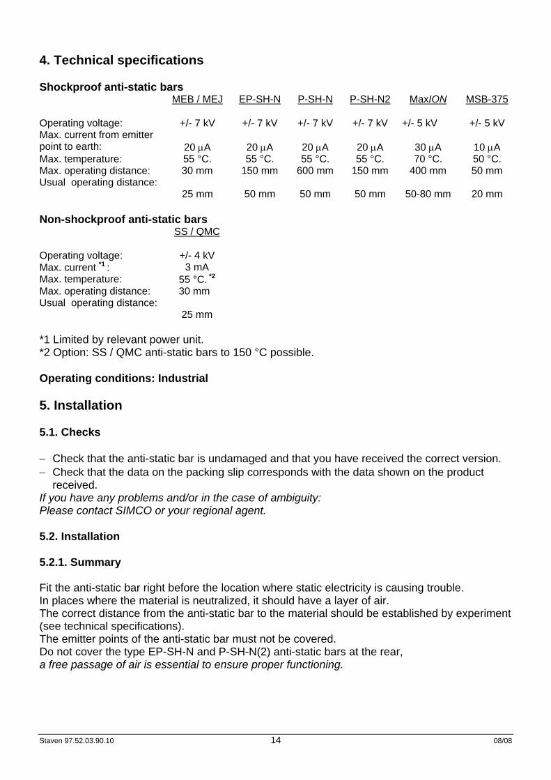
4. Technical specifications Shockproof anti-static bars MEB / MEJ EP-SH-N P-SH-N P-SH-N2 MaxION MSB-375 Operating voltage: +/- 7 kV +/- 7 kV +/- 7 kV +/- 7 kV +/- 5 kV +/- 5 kV Max. current from emitter point to earth:
20 μA
20 μA
20 μA
20 μA
30 μA
10 μA
Max. temperature: 55 °C. 55 °C. 55 °C. 55 °C. 70 °C. 50 °C. Max. operating distance: 30 mm 150 mm 600 mm 150 mm 400 mm 50 mm Usual operating distance:
25 mm
50 mm
50 mm
50 mm
50-80 mm
20 mm
Non-shockproof anti-static bars SS / QMC Operating voltage: +/- 4 kV Max. current *1 : 3 mA Max. temperature: 55 °C. *2 Max. operating distance: 30 mm Usual operating distance:
25 mm
*1 Limited by relevant power unit. *2 Option: SS / QMC anti-static bars to 150 °C possible. Operating conditions: Industrial 5. Installation 5.1. Checks − Check that the anti-static bar is undamaged and that you have received the correct version. − Check that the data on the packing slip corresponds with the data shown on the product
received. If you have any problems and/or in the case of ambiguity: Please contact SIMCO or your regional agent. 5.2. Installation 5.2.1. Summary Fit the anti-static bar right before the location where static electricity is causing trouble. In places where the material is neutralized, it should have a layer of air. The correct distance from the anti-static bar to the material should be established by experiment (see technical specifications). The emitter points of the anti-static bar must not be covered. Do not cover the type EP-SH-N and P-SH-N(2) anti-static bars at the rear, a free passage of air is essential to ensure proper functioning.
Staven 97.52.03.90.10 15 08/08
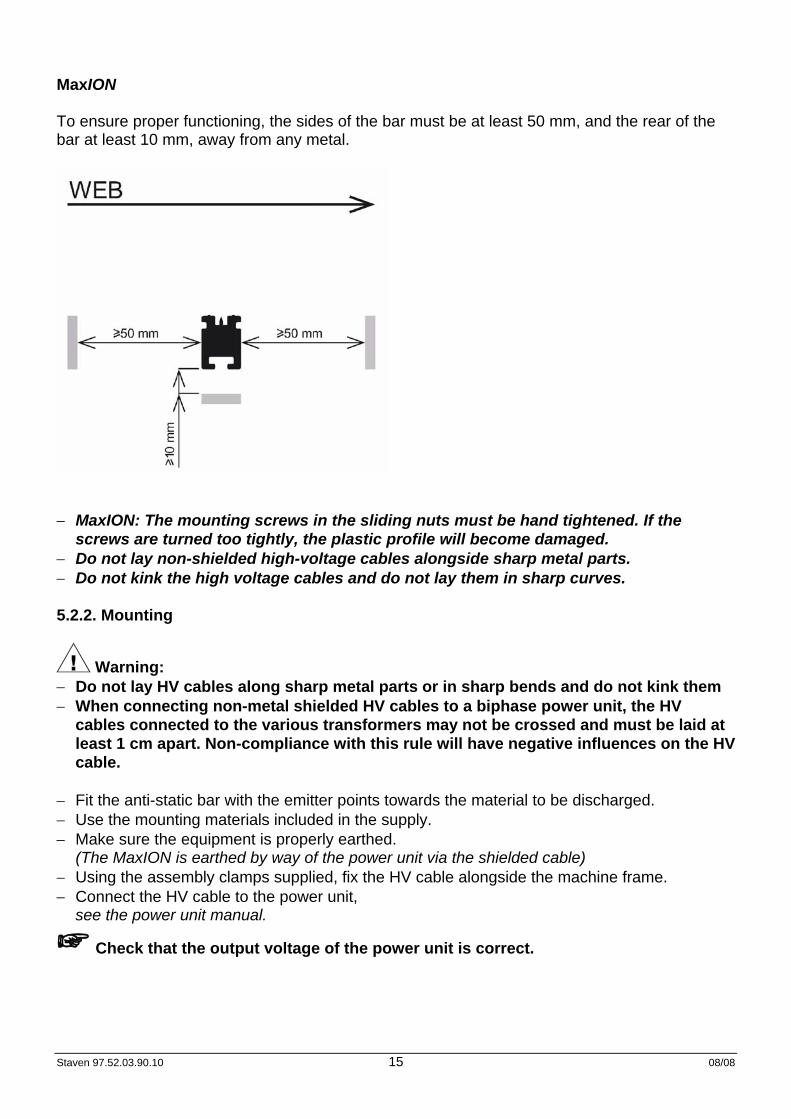
MaxION To ensure proper functioning, the sides of the bar must be at least 50 mm, and the rear of the bar at least 10 mm, away from any metal.
− MaxION: The mounting screws in the sliding nuts must be hand tightened. If the
screws are turned too tightly, the plastic profile will become damaged. − Do not lay non-shielded high-voltage cables alongside sharp metal parts. − Do not kink the high voltage cables and do not lay them in sharp curves. 5.2.2. Mounting
Warning: − Do not lay HV cables along sharp metal parts or in sharp bends and do not kink them − When connecting non-metal shielded HV cables to a biphase power unit, the HV
cables connected to the various transformers may not be crossed and must be laid at least 1 cm apart. Non-compliance with this rule will have negative influences on the HV cable.
− Fit the anti-static bar with the emitter points towards the material to be discharged. − Use the mounting materials included in the supply. − Make sure the equipment is properly earthed.
(The MaxION is earthed by way of the power unit via the shielded cable) − Using the assembly clamps supplied, fix the HV cable alongside the machine frame. − Connect the HV cable to the power unit,
see the power unit manual.
Check that the output voltage of the power unit is correct.
Staven 97.52.03.90.10 16 08/08
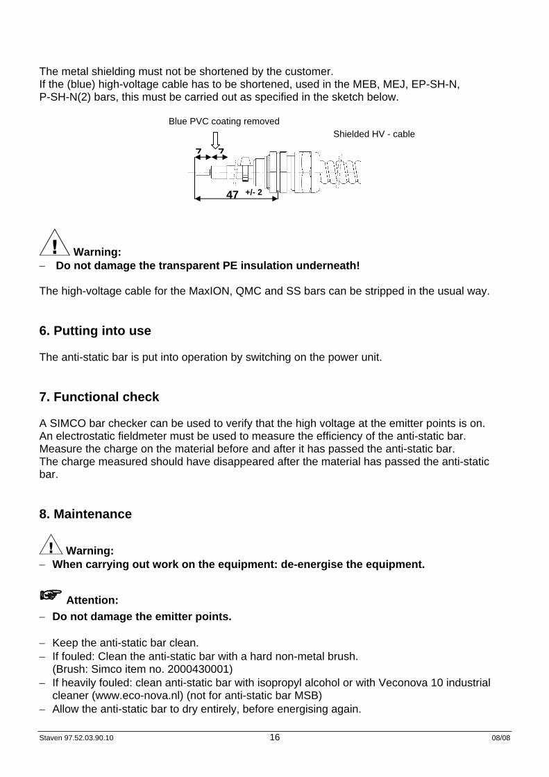
The metal shielding must not be shortened by the customer. If the (blue) high-voltage cable has to be shortened, used in the MEB, MEJ, EP-SH-N, P-SH-N(2) bars, this must be carried out as specified in the sketch below.
Blue PVC coating removed Shielded HV - cable
Warning: − Do not damage the transparent PE insulation underneath! The high-voltage cable for the MaxION, QMC and SS bars can be stripped in the usual way. 6. Putting into use The anti-static bar is put into operation by switching on the power unit. 7. Functional check A SIMCO bar checker can be used to verify that the high voltage at the emitter points is on. An electrostatic fieldmeter must be used to measure the efficiency of the anti-static bar. Measure the charge on the material before and after it has passed the anti-static bar. The charge measured should have disappeared after the material has passed the anti-static bar. 8. Maintenance
Warning: − When carrying out work on the equipment: de-energise the equipment.
Attention: − Do not damage the emitter points. − Keep the anti-static bar clean. − If fouled: Clean the anti-static bar with a hard non-metal brush.
(Brush: Simco item no. 2000430001) − If heavily fouled: clean anti-static bar with isopropyl alcohol or with Veconova 10 industrial
cleaner (www.eco-nova.nl) (not for anti-static bar MSB) − Allow the anti-static bar to dry entirely, before energising again.
47 +/- 2
77
Staven 97.52.03.90.10 17 08/08
9. Faults Problem Cause Remedy No/poor ionisation. No high voltage. Restore high voltage. Anti-static bar is fouled. Clean anti-static bar. Emitter points are
damaged. Return bar for repair.
Emitter points are covered. Remove the cover. No high voltage on emitter points.
High voltage power unit is defective.
Repair high voltage power unit.
Short circuit in the HV cable or anti-static bar.
Eliminate short circuit or return the bar for repair.
Table 1: faults 10 Repairs
Warning: − When carrying out work on the equipment: de-energise the equipment. The anti-static bar does not comprise any parts which can be replaced by client. SIMCO recommends that you return the bar if repairs are required. Request an RMA form by sending an e-mail to [email protected]. Pack the bar properly and clearly state the reason for return. 11. Disposal Adhere to the applicable local environmental and other rules when disposing of the equipment.
Staven 97.52.03.90.10 18 08/08
NOTICE D'UTILISATION DES BARRES IONISANTES 1. Introduction Lire attentivement les instructions qui suivent avant toute installation et utilisation du système. Ces instructions doivent être observées pour assurer le bon fonctionnement de l’équipement et donner droit à sa garantie. Les stipulations de garantie sont décrites dans les conditions générales de vente de SIMCO (Nederland) B.V. Cette notice s'applique aux barres résistantes aux chocs de type MEB, MEJ, EP-SH-N, P-SH-N(2) MaxION et MSB-375 et aux barres non résistantes aux chocs de type Super Service (SS) et QMC. 2. Sécurité − Les barres ionisantes SIMCO sont exclusivement destinées à neutraliser l’électricité statique. − Ne pas monter les barres non résistantes aux chocs dans un environnement avec des
matières très inflammables. − L’installation électrique, l’entretien et les réparations doivent être réalisés par un électricien
qualifié. − En cas d’intervention sur l’équipement, mettre l’équipement hors tension. − L’appareil perd son homologation CE en cas de modification, d’adaptation, etc., sans accord
préalable écrit. − Assurez une bonne mise à la terre de l’équipement.
La mise à la terre est nécessaire pour assurer un bon fonctionnement et prévenir tout choc électrique en cas de contact.
− Ne pas toucher les éléments sous tension des barres SS et QMC Vous risqueriez de recevoir une décharge électrique.
3. Application et fonctionnement Les barres ionisantes SIMCO sont conçues pour neutraliser l’électricité statique sur des feuilles, bandes et autres matériaux à surface plane. Les barres ionisantes ne peuvent être utilisées qu’en combinaison avec un transformateur de haute tension SIMCO. La haute tension génère dans les pointes de la barre ionisante un champ électrique qui transforme les molécules d’air autour des pointes ionisantes en ions positifs et négatifs. Lorsqu’une matière chargée arrive à proximité des pointes ionisantes, cela entraîne un échange d’électrons jusqu’à ce que la charge de la matière soit neutralisée. Les pointes des barres ionisantes résistantes aux chocs sont de type MEB, MEJ, EP-SH-N, P-SH-N(2) MaxION et MSB-375 à couplage capacitif avec la haute tension et ne présentent donc pas de danger de contact. Les pointes des barres ionisantes non résistantes aux chocs de type Super Service (SS) et QMC sont directement couplées à la haute tension et tout contact avec ces pointes provoque un choc électrique.
Staven 97.52.03.90.10 19 08/08
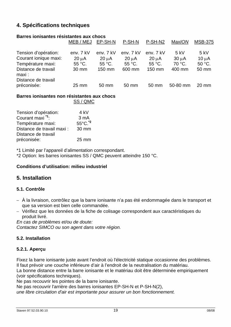
4. Spécifications techniques Barres ionisantes résistantes aux chocs MEB / MEJ EP-SH-N P-SH-N P-SH-N2 MaxION MSB-375 Tension d’opération: env. 7 kV env. 7 kV env. 7 kV env. 7 kV 5 kV 5 kV Courant ionique maxi: 20 μA 20 μA 20 μA 20 μA 30 μA 10 μA Température maxi: 55 °C. 55 °C. 55 °C. 55 °C. 70 °C. 50 °C. Distance de travail maxi :
30 mm 150 mm 600 mm 150 mm 400 mm 50 mm
Distance de travail préconisée:
25 mm
50 mm
50 mm
50 mm
50-80 mm
20 mm
Barres ionisantes non résistantes aux chocs SS / QMC Tension d’opération: 4 kV Courant maxi *1: 3 mA Température maxi: 55°C.*2 Distance de travail maxi : 30 mm Distance de travail préconisée:
25 mm
*1 Limité par l’appareil d’alimentation correspondant. *2 Option: les barres ionisantes SS / QMC peuvent atteindre 150 °C. Conditions d’utilisation: milieu industriel 5. Installation 5.1. Contrôle − À la livraison, contrôlez que la barre ionisante n’a pas été endommagée dans le transport et
que sa version est bien celle commandée. − Vérifiez que les données de la fiche de colisage correspondent aux caractéristiques du
produit livré. En cas de problèmes et/ou de doute: Contactez SIMCO ou son agent dans votre région. 5.2. Installation 5.2.1. Aperçu Fixez la barre ionisante juste avant l’endroit où l'électricité statique occasionne des problèmes. Il faut prévoir une couche inférieure d’air à l’endroit de la neutralisation du matériau. La bonne distance entre la barre ionisante et le matériau doit être déterminée empiriquement (voir spécifications techniques). Ne pas recouvrir les pointes de la barre ionisante. Ne pas recouvrir l'arrière des barres ionisantes EP-SH-N et P-SH-N(2), une libre circulation d'air est importante pour assurer un bon fonctionnement.
Staven 97.52.03.90.10 20 08/08
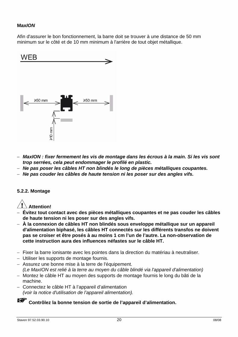
MaxION Afin d'assurer le bon fonctionnement, la barre doit se trouver à une distance de 50 mm minimum sur le côté et de 10 mm minimum à l'arrière de tout objet métallique.
− MaxION : fixer fermement les vis de montage dans les écrous à la main. Si les vis sont
trop serrées, cela peut endommager le profilé en plastic. − Ne pas poser les câbles HT non blindés le long de pièces métalliques coupantes. − Ne pas couder les câbles de haute tension ni les poser sur des angles vifs. 5.2.2. Montage
Attention! − Évitez tout contact avec des pièces métalliques coupantes et ne pas couder les câbles
de haute tension ni les poser sur des angles vifs. − À la connexion de câbles HT non blindés sous enveloppe métallique sur un appareil
d'alimentation biphasé, les câbles HT connectés sur les différents transfos ne doivent pas se croiser et être posés à au moins 1 cm l’un de l’autre. La non-observation de cette instruction aura des influences néfastes sur le câble HT.
− Fixer la barre ionisante avec les pointes dans la direction du matériau à neutraliser. − Utiliser les supports de montage fournis. − Assurez une bonne mise à la terre de l'équipement.
(Le MaxION est relié à la terre au moyen du câble blindé via l'appareil d'alimentation) − Montez le câble HT au moyen des supports de montage fournis le long du bâti de la
machine. − Connectez le câble HT à l’appareil d’alimentation
(voir la notice d'utilisation de l’appareil alimentation).
Contrôlez la bonne tension de sortie de l’appareil d’alimentation.
Staven 97.52.03.90.10 21 08/08
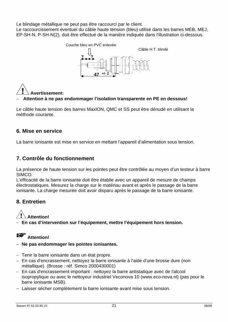
Le blindage métallique ne peut pas être raccourci par le client. Le raccourcissement éventuel du câble haute tension (bleu) utilisé dans les barres MEB, MEJ, EP-SH-N, P-SH-N(2), doit être effectué de la manière indiquée dans l'illustration ci-dessous.
Couche bleu en PVC enlevée Câble H.T. blindé
Avertissement: − Attention à ne pas endommager l’isolation transparente en PE en dessous! Le câble haute tension des barres MaxION, QMC et SS peut être dénudé en utilisant la méthode courante. 6. Mise en service La barre ionisante est mise en service en mettant l’appareil d’alimentation sous tension. 7. Contrôle du fonctionnement La présence de haute tension sur les pointes peut être contrôlée au moyen d’un testeur à barre SIMCO. L’efficacité de la barre ionisante doit être établie avec un appareil de mesure de champs électrostatiques. Mesurez la charge sur le matériau avant et après le passage de la barre ionisante. La charge mesurée doit avoir disparu après le passage de la barre ionisante. 8. Entretien
Attention! − En cas d’intervention sur l’équipement, mettre l’équipement hors tension.
Attention! − Ne pas endommager les pointes ionisantes. − Tenir la barre ionisante dans un état propre. − En cas d’encrassement, nettoyez la barre ionisante à l’aide d’une brosse dure (non
métallique). (Brosse : réf. Simco 2000430001) − En cas d'encrassement important : nettoyez la barre antistatique avec de l'alcool
isopropylique ou avec le nettoyeur industriel Veconova 10 (www.eco-nova.nl) (pas pour le barre ionisante MSB).
− Laisser sécher complètement la barre ionisante avant mise sous tension.
47 +/- 2
77
Staven 97.52.03.90.10 22 08/08
9. Pannes Problème Cause Solution Pas d’ionisation/ionisation insuffisante.
Pas de haute tension. Assurer à nouveau la haute tension.
Barre ionisante encrassée. Nettoyer la barre ionisante. Les pointes ionisantes sont
endommagées. Retourner la barre pour réparation.
Les pointes ionisantes sont recouvertes.
Enlever l’obstruction.
Pas de haute tension sur les pointes ionisantes.
Le transformateur de haute tension est défaillant.
Réparer le transformateur de haute tension.
Court-circuit dans le câble HT ou la barre ionisante.
Éliminer le court-circuit ou retourner la barre pour réparation.
tableau 1: pannes 10 Réparations
Attention! − En cas d’intervention sur l’équipement, mettre l’équipement hors tension. La barre ionisante ne comporte pas d’éléments pouvant être réparés par le client. SIMCO recommande de retourner la barre pour la faire réparer. Pour ce faire, demandez un formulaire RMA par e-mail à [email protected]. Emballez solidement la barre et indiquez clairement la raison du retour. 11. Mise au rebut Observez les lois nationales en vigueur en cas de mise au rebut de l’appareil.

![MSB 17[Ontgiften]](https://static.fdocuments.nl/doc/165x107/577cd1211a28ab9e7893b527/msb-17ontgiften.jpg)


![SH-M11k-tai.sharp.co.jp/support/other/shm11/manual/index_v2/pdf/SH-M11_… · 1 本体付属品 急速充電器 [acアダプター(sh‐ac05)] sh‐m11本体 (保証書付き)](https://static.fdocuments.nl/doc/165x107/6039c91962877370730d8559/sh-m11k-taisharpcojpsupportothershm11manualindexv2pdfsh-m11-1-oe.jpg)