
M. K. Salman, R. B. Ahmad, A. Yahya Novi pristup za ...
9
M. K. Salman, R. B. Ahmad, A. Yahya Novi pristup za učinkovito korištenje resursa u WiMAX mobilnim mrežama ISSN 1330-3651(Print), ISSN 1848-6339 (Online) UDC/UDK 621.391:004.735.05 A NEW APPROACH FOR EFFICIENT UTILIZATION OF RESOURCES IN WIMAX CELLULAR NETWORKS M. K. Salman, R. B. Ahmad, Abid Yahya Preliminary notes This paper proposes new static resource utilization (SRU) approach by using the fractional frequency reuse (FFR) technique to enhance resource exploitation in Worldwide Interoperability for Microwave Access (WiMAX) 802.16e. This approach not only efficiently enhances resource exploitation in the base station (BS) but also increases the data rate and number of served users. This work considers the downlink sub-frame of WiMAX BS by using the partial usage of sub-channel mode and the orthogonal frequency division multiplexing access. Five cases were included as a trade-off study to identify the best way of utilizing BS resources in the FFR technique. Theoretical analysis was conducted to present a new formula for the FFR data rate. Simulation results (cases 5 and 4) reveal that the proposed approach has an advantage over the traditional FFR technique in various metrics. The number of served users and slots utilized was increased by 100 % when case 5 was considered. By contrast, the data rate (8,69 Mbit/s), subcarrier efficiency (2,02 bit/subcarrier/burst), and spectral efficiency (0,869 bit/s/H) were enhanced when case 4 was considered. The efficient utilization of bandwidth and resources has made the proposed approach a compelling candidate for cellular network deployment. Keywords: BS performance, Data Rate, FFR, Resource Utilization, Serving Users, Spectral Efficiency, Static Mode, WiMAX Novi pristup za učinkovito korištenje resursa u WiMAX mobilnim mrežama Prethodno priopćenje U radu se predlaže novi pristup primjene statičkog resursa (SRU) pomoću tehnike ponovne upotrebe frakcijske frekvencije (FFR) za poboljšanje iskorištavanja resursa u interoperabilnosti širom svijeta za mikrovalni pristup (WiMAX) 802.16e. Ovaj pristup ne samo da učinkovito poboljšava iskorištavanje resursa u baznoj stanici (BS), već i povećava brzinu prijenosa podataka i broj posluženih korisnika. Ovaj rad razmatra silaznu vezu pod- okvira WiMAX BS uporabom djelomične uporabe potkanalnog načina i pristupa ortogonalnog multipleksiranja. Pet je slučajeva bilo uključeno, kao slučajevi u razmjeni, u identifikaciji najboljeg načina iskorištavanja resursa BS u FFR tehnici. Provedena je teorijska analiza u svrhu predstavljanja nove formule za stopu FFR podataka. Rezultati simulacije (slučajevi 5 i 4) otkrivaju da takav pristup ima prednost u odnosu na tradicionalnu tehniku FFR u raznim metrikama. Broj posluženih korisnika i upotrijebljenih slotova povećan je za 100 % u razmatranju slučaja 5. Nasuprot tome, brzina prijenosa podataka (8,69 Mbit/s), učinkovitost subnositelj (2,02 bit/subnositelj/burst), i iskoristivost spektra (0,869 bit/s/H) poboljšani su kod slučaja 4. Zbog učinkovite uporabe širine pojasa i resursa predloženi je pristup uvjerljiv kandidat za postavljanje ćelijske mreže. Ključne riječi: BS performansa, brzina podataka, FFR, uporaba resursa, posluživanje korisnika, iskoristivost spektra, statički način, WiMAX 1 Introduction The Worldwide Interoperability for Microwave Access (WiMAX) is a broadband evolution that supports high- speed connection. WiMAX arose with several standards [1]. 802.16-2004 or fixed WiMAX can be considered an alternative to the digital subscriber line (DSL) or cable modem because fixed WiMAX can provide similar air communication as that of DSL [2]. In 2005, the standard 802.16e-2005 emerged to support mobile users with vehicle speeds [3]. Both standards used orthogonal frequency division multiplexing (OFDM) as their basic technique. To enable WiMAX to transmit user data simultaneously, a multiple access scheme such as the orthogonal frequency division multiple access (OFDMA) should be used. When using the OFDMA, the data transmission period may contain more than one user data. Therefore, the OFDMA offers more resilience and better user data manageability in the down link (DL) or uplink (UL) sub-frames [1]. WiMAX base station (BS) can be deployed in cellular network, where it consists of adjacent clusters and each cluster contains several cells. OFDMA naturally uses orthogonal subcarriers. OFDMA solves the problem of inter-symbol interference but not the problem of inter-cell interference (ICI). Several techniques have been used to overcome the ICI problem, including frequency planning, FFR, segmentation (sectoring), and subcarrier permutation [4]. In frequency planning, the available bandwidth (BW) is divided among cells or sectors. In contrast to frequency planning, the available BW in FFR technique is used to serve users near the BS, whereas users far away from the BS utilize 1/3 of the available BW. As a result, the spectral efficiency is increased for users near the BS and dwindles for users far away from the BS. The FFR DL sub-frame structure is shown in Fig. 1a, and the virtual frequency distribution of this technique appears in Fig. 1b. The three bands (F1, F2, and F3) represent different groups of sub- channels in the same BW. The available resource in the DL sub-frame is divided into R1 zone and R3 zone. The cell area is also divided into two regions: the cell centre and the cell border [5]. Figure 1 FFR technique deployment Tehnički vjesnik 21, 6(2014), 1385-1393 1385
Transcript of M. K. Salman, R. B. Ahmad, A. Yahya Novi pristup za ...
M. K. Salman, R. B. Ahmad, A. Yahya Novi pristup za učinkovito korištenje resursa u WiMAX mobilnim mrežama
ISSN 1330-3651(Print), ISSN 1848-6339 (Online) UDC/UDK 621.391:004.735.05
A NEW APPROACH FOR EFFICIENT UTILIZATION OF RESOURCES IN WIMAX CELLULAR NETWORKS M. K. Salman, R. B. Ahmad, Abid Yahya
Preliminary notes This paper proposes new static resource utilization (SRU) approach by using the fractional frequency reuse (FFR) technique to enhance resource exploitation in Worldwide Interoperability for Microwave Access (WiMAX) 802.16e. This approach not only efficiently enhances resource exploitation in the base station (BS) but also increases the data rate and number of served users. This work considers the downlink sub-frame of WiMAX BS by using the partial usage of sub-channel mode and the orthogonal frequency division multiplexing access. Five cases were included as a trade-off study to identify the best way of utilizing BS resources in the FFR technique. Theoretical analysis was conducted to present a new formula for the FFR data rate. Simulation results (cases 5 and 4) reveal that the proposed approach has an advantage over the traditional FFR technique in various metrics. The number of served users and slots utilized was increased by 100 % when case 5 was considered. By contrast, the data rate (8,69 Mbit/s), subcarrier efficiency (2,02 bit/subcarrier/burst), and spectral efficiency (0,869 bit/s/H) were enhanced when case 4 was considered. The efficient utilization of bandwidth and resources has made the proposed approach a compelling candidate for cellular network deployment. Keywords: BS performance, Data Rate, FFR, Resource Utilization, Serving Users, Spectral Efficiency, Static Mode, WiMAX Novi pristup za učinkovito korištenje resursa u WiMAX mobilnim mrežama
Prethodno priopćenje U radu se predlaže novi pristup primjene statičkog resursa (SRU) pomoću tehnike ponovne upotrebe frakcijske frekvencije (FFR) za poboljšanje iskorištavanja resursa u interoperabilnosti širom svijeta za mikrovalni pristup (WiMAX) 802.16e. Ovaj pristup ne samo da učinkovito poboljšava iskorištavanje resursa u baznoj stanici (BS), već i povećava brzinu prijenosa podataka i broj posluženih korisnika. Ovaj rad razmatra silaznu vezu pod-okvira WiMAX BS uporabom djelomične uporabe potkanalnog načina i pristupa ortogonalnog multipleksiranja. Pet je slučajeva bilo uključeno, kao slučajevi u razmjeni, u identifikaciji najboljeg načina iskorištavanja resursa BS u FFR tehnici. Provedena je teorijska analiza u svrhu predstavljanja nove formule za stopu FFR podataka. Rezultati simulacije (slučajevi 5 i 4) otkrivaju da takav pristup ima prednost u odnosu na tradicionalnu tehniku FFR u raznim metrikama. Broj posluženih korisnika i upotrijebljenih slotova povećan je za 100 % u razmatranju slučaja 5. Nasuprot tome, brzina prijenosa podataka (8,69 Mbit/s), učinkovitost subnositelj (2,02 bit/subnositelj/burst), i iskoristivost spektra (0,869 bit/s/H) poboljšani su kod slučaja 4. Zbog učinkovite uporabe širine pojasa i resursa predloženi je pristup uvjerljiv kandidat za postavljanje ćelijske mreže. Ključne riječi: BS performansa, brzina podataka, FFR, uporaba resursa, posluživanje korisnika, iskoristivost spektra, statički način, WiMAX 1 Introduction
The Worldwide Interoperability for Microwave Access
(WiMAX) is a broadband evolution that supports high-speed connection. WiMAX arose with several standards [1]. 802.16-2004 or fixed WiMAX can be considered an alternative to the digital subscriber line (DSL) or cable modem because fixed WiMAX can provide similar air communication as that of DSL [2]. In 2005, the standard 802.16e-2005 emerged to support mobile users with vehicle speeds [3]. Both standards used orthogonal frequency division multiplexing (OFDM) as their basic technique. To enable WiMAX to transmit user data simultaneously, a multiple access scheme such as the orthogonal frequency division multiple access (OFDMA) should be used. When using the OFDMA, the data transmission period may contain more than one user data. Therefore, the OFDMA offers more resilience and better user data manageability in the down link (DL) or uplink (UL) sub-frames [1].
WiMAX base station (BS) can be deployed in cellular network, where it consists of adjacent clusters and each cluster contains several cells. OFDMA naturally uses orthogonal subcarriers. OFDMA solves the problem of inter-symbol interference but not the problem of inter-cell interference (ICI). Several techniques have been used to overcome the ICI problem, including frequency planning, FFR, segmentation (sectoring), and subcarrier permutation [4].
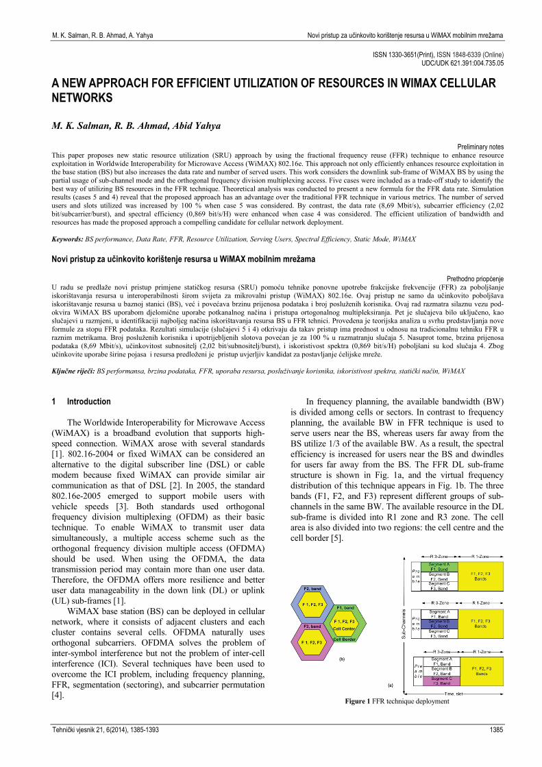
In frequency planning, the available bandwidth (BW) is divided among cells or sectors. In contrast to frequency planning, the available BW in FFR technique is used to serve users near the BS, whereas users far away from the BS utilize 1/3 of the available BW. As a result, the spectral efficiency is increased for users near the BS and dwindles for users far away from the BS. The FFR DL sub-frame structure is shown in Fig. 1a, and the virtual frequency distribution of this technique appears in Fig. 1b. The three bands (F1, F2, and F3) represent different groups of sub-channels in the same BW. The available resource in the DL sub-frame is divided into R1 zone and R3 zone. The cell area is also divided into two regions: the cell centre and the cell border [5].
Figure 1 FFR technique deployment
Tehnički vjesnik 21, 6(2014), 1385-1393 1385
A new approach for efficient utilization of resources in WIMAX cellar networks M. K. Salman, R. B. Ahmad, A. Yahya
Users in the call centre are served by the R1 zone, and users in the cell border are served by segment (A) in the R3 zone. The partial usage of sub-channel (PUSC) permutation mode should be used to divide the R3 zone into three segments. Segment (A) in R3 zone is used to provide 1/3 of the available BW to serve users in the cell border. However, the sacrifice in resources and BW is mandatory to ensure that only one type of frequency band will be used in the cell border for each BS to mitigate the ICI [6].
Fractional frequency reuse (FFR) has been investigated by researchers in various aspects, such as quality of service, resource management, cell throughput, and zone assignment problem. In [7], the coverage area and throughput improved when signal to interference plus noise ratio (SINR) and zone resizing were considered according to the users distribution in the cell. Another throughput enhancement on the dynamic zone assignment and switching technique is proposed by [8], in which the cell area is divided by four and each zone has its own share of bandwidth (BW). The throughput in malty FFR cells is maximized by [9] when applying slot algorithm based on zone switching diversity, while guarantee the Quality of Service (QoS) requirements for real-time and non-real-time service flows. The two functional entities Radio Resource Agent (RRA) and Radio Resource Controller (RRC) ensure the resources are hierarchically assigned and the QoS for users in the inner and outer area are achieved. In [10], resources are efficiently managed and granted to users according to the load balancing method. The new method considers the measured SINR and the available resources in the DL sub-frame. As a result, these two metrics enhance the network performance in terms of probabilities of user-blocking, user-outage, and user-reject, as well as percentage of resource utilization.
The load balancing method is applied in a different manner in [11]. The load balancing method overcame the weakness of the SINR method by considering the channel condition and the available resources in the target zone. The network performance improved in terms of blocking ratio and offered bit rate. FFR analysis in rural environments was presented by [12], in which the SINR and user's pathos are used as metrics to assign resources. The inner area radius becomes the key element in increasing the overall system throughput. The FFR analysis is presented by [13], in different aspects. The performance of FFR was examined under different shadowing values and path loss effect. The ergodic capacity used as performance measurement shows a fast and accurate analysis of the performances of FFR. Ref. [14] proposed the dynamical resource allocation scheme to increase the subcarriers distributed per user on the basis of the channel information available. In contrast, researchers in [15] proposed Generalized FFR (GFFR) scheme to assignee resources to cell edge users. In GFFR the frequency band used for cell edge zone can be partitioned into any number of sub-bands, where the number of sub-bands allocated to the edge zone is specified by the cell itself. In addition, the power per cell is controlled by GFFR algorithm, where it is variable from cell to another, thus to improve the signal gains.
The authors in [16] designed their study toward obtaining an optimal frequency planning strategy according to the frequency reuse pattern and the subcarrier
permutation mode, where the subcarriers on the same or different PermBases are taken into consideration. Similarly, a new frequency partitioning pattern was suggested by [17] to improve throughput. In the study of [17], the cell area is divided into two, and the sub-channels are divided into four. In addition, the users in the centre area can utilize two types of frequency bands: the common frequency in the cell centre and the edge frequency in the cell boundaries. Edge frequency will not be reused in the edges of neighbour cells; thus, the SINR of the centre users are improved, providing opportunity to use high modulation and coding scheme (MCS). In the same topic, four frequencies distribution schemes were proposed by [18], to enhance the FFR performance over video multicasting. Moreover, resource allocation method was proposed to provide additional resources for users in the cell centre as well as cell edge. Three stages of BS power are proposed to reduce the inter-cell interference (ICI) among neighbour cells, which increase the quality of received video. The results showed that the proposed scheme increases the resource allocation about 10 % and it also enhances the video quality compared to traditional FFR.
However, the problem of resource wastage when using the traditional FFR technique, specifically, the unused segments in the DL sub-frame, was not considered by the above studies. Therefore, the current paper proposes a new static resource utilization (SRU) approach to address this research gap. This new approach enhances the performance of WiMAX BS in terms of resource utilization, data rate, subcarrier efficiency, number of served users, and spectral efficiency.
This paper is organized as follows. Section 2 presents the proposed model design with mathematical formulation. The simulation results are reported in Section 3, and the analytic performance evaluation is presented in Section 4. Finally, Section 5 concludes the study.
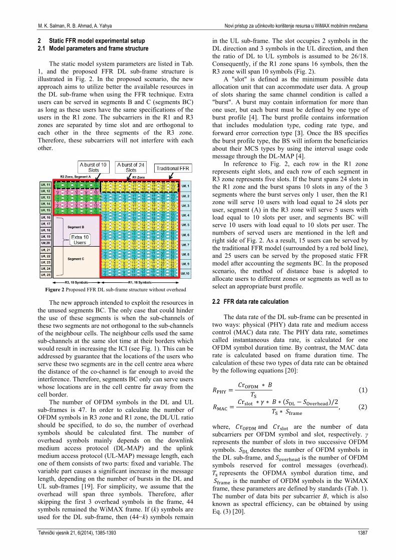
Table 1 Model parameters Item desecration Item value
Bandwidth (BW) 10 MB Permutation mode PUSC FFT Size 1024 Subcarrier frequency spacing Δf 10,94 kHz Useful symbol time (Tb = 1/Δf) 91,4 ms G, is the ratio of CP(a) time to useful time 1/8 for 10 MHz BW
Guard time (Tg =Tb·G) 11,43 ms OFDMA symbol duration (Ts = Tb + Tg)
102,9 ms
Number of OFDM symbols (Sframe) 48,6
(in frame of 5 ms) Sampling factor 28/25 for 10 MHz BW Frame duration (Tf=Ts·Sframe) 5 ms Number of slots per two successive OFDM symbols (γ) 30
Number of subcarriers per slot ( 𝐶𝐶rslot)
48
Cell centre radius 750 m Cell border radius 1000 m DL/UL ration 29/18 Number of users per trial 28 Duplexing mode, Time Division Duplex TDD
(a) CP is cyclic prefix
1386 Technical Gazette 21, 6(2014), 1385-1393
M. K. Salman, R. B. Ahmad, A. Yahya Novi pristup za učinkovito korištenje resursa u WiMAX mobilnim mrežama
2 Static FFR model experimental setup 2.1 Model parameters and frame structure
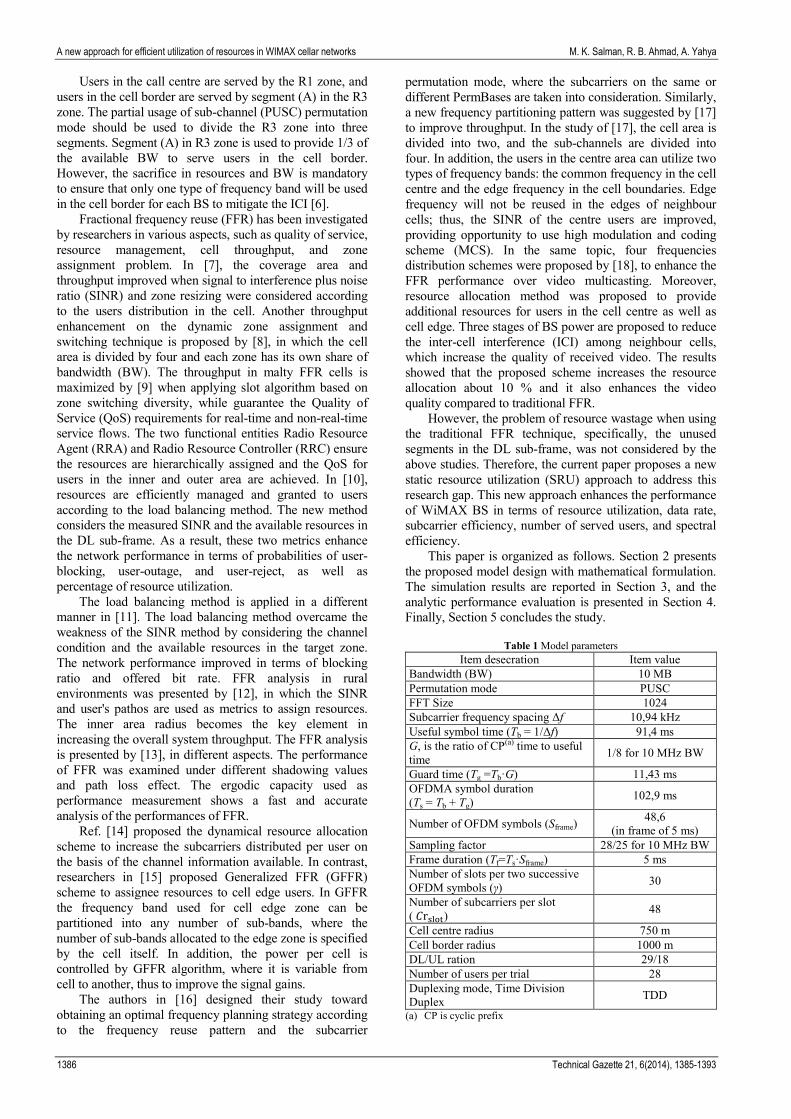
The static model system parameters are listed in Tab. 1, and the proposed FFR DL sub-frame structure is illustrated in Fig. 2. In the proposed scenario, the new approach aims to utilize better the available resources in the DL sub-frame when using the FFR technique. Extra users can be served in segments B and C (segments BC) as long as these users have the same specifications of the users in the R1 zone. The subcarriers in the R1 and R3 zones are separated by time slot and are orthogonal to each other in the three segments of the R3 zone. Therefore, these subcarriers will not interfere with each other.
Figure 2 Proposed FFR DL sub-frame structure without overhead
The new approach intended to exploit the resources in
the unused segments BC. The only case that could hinder the use of these segments is when the sub-channels of these two segments are not orthogonal to the sub-channels of the neighbour cells. The neighbour cells used the same sub-channels at the same slot time at their borders which would result in increasing the ICI (see Fig. 1). This can be addressed by guarantee that the locations of the users who serve these two segments are in the cell centre area where the distance of the co-channel is far enough to avoid the interference. Therefore, segments BC only can serve users whose locations are in the cell centre far away from the cell border.
The number of OFDM symbols in the DL and UL sub-frames is 47. In order to calculate the number of OFDM symbols in R3 zone and R1 zone, the DL/UL ratio should be specified, to do so, the number of overhead symbols should be calculated first. The number of overhead symbols mainly depends on the downlink medium access protocol (DL-MAP) and the uplink medium access protocol (UL-MAP) message length, each one of them consists of two parts: fixed and variable. The variable part causes a significant increase in the message length, depending on the number of bursts in the DL and UL sub-frames [19]. For simplicity, we assume that the overhead will span three symbols. Therefore, after skipping the first 3 overhead symbols in the frame, 44 symbols remained the WiMAX frame. If (k) symbols are used for the DL sub-frame, then (44−k) symbols remain
in the UL sub-frame. The slot occupies 2 symbols in the DL direction and 3 symbols in the UL direction, and then the ratio of DL to UL symbols is assumed to be 26/18. Consequently, if the R1 zone spans 16 symbols, then the R3 zone will span 10 symbols (Fig. 2).
A "slot" is defined as the minimum possible data allocation unit that can accommodate user data. A group of slots sharing the same channel condition is called a "burst". A burst may contain information for more than one user, but each burst must be defined by one type of burst profile [4]. The burst profile contains information that includes modulation type, coding rate type, and forward error correction type [3]. Once the BS specifies the burst profile type, the BS will inform the beneficiaries about their MCS types by using the interval usage code message through the DL-MAP [4].
In reference to Fig. 2, each row in the R1 zone represents eight slots, and each row of each segment in R3 zone represents five slots. If the burst spans 24 slots in the R1 zone and the burst spans 10 slots in any of the 3 segments where the burst serves only 1 user, then the R1 zone will serve 10 users with load equal to 24 slots per user, segment (A) in the R3 zone will serve 5 users with load equal to 10 slots per user, and segments BC will serve 10 users with load equal to 10 slots per user. The numbers of served users are mentioned in the left and right side of Fig. 2. As a result, 15 users can be served by the traditional FFR model (surrounded by a red bold line), and 25 users can be served by the proposed static FFR model after accounting the segments BC. In the proposed scenario, the method of distance base is adopted to allocate users to different zones or segments as well as to select an appropriate burst profile.
2.2 FFR data rate calculation
The data rate of the DL sub-frame can be presented in two ways: physical (PHY) data rate and medium access control (MAC) data rate. The PHY data rate, sometimes called instantaneous data rate, is calculated for one OFDM symbol duration time. By contrast, the MAC data rate is calculated based on frame duration time. The calculation of these two types of data rate can be obtained by the following equations [20]:
𝑅𝑅PHY = 𝐶𝐶rOFDM ∗ 𝐵𝐵
𝑇𝑇S (1)
𝑅𝑅MAC = 𝐶𝐶rslot ∗ 𝛾𝛾 ∗ 𝐵𝐵 ∗ (𝑆𝑆DL − 𝑆𝑆Overhead)/2
𝑇𝑇S ∗ 𝑆𝑆frame, (2)
where, 𝐶𝐶rOFDM and 𝐶𝐶rslot are the number of data subcarriers per OFDM symbol and slot, respectively. γ represents the number of slots in two successive OFDM symbols. 𝑆𝑆DL denotes the number of OFDM symbols in the DL sub-frame, and 𝑆𝑆overhead is the number of OFDM symbols reserved for control messages (overhead). 𝑇𝑇s represents the OFDMA symbol duration time, and 𝑆𝑆frame is the number of OFDM symbols in the WiMAX frame, these parameters are defined by standards (Tab. 1). The number of data bits per subcarrier B, which is also known as spectral efficiency, can be obtained by using Eq. (3) [20].
Tehnički vjesnik 21, 6(2014), 1385-1393 1387
A new approach for efficient utilization of resources in WIMAX cellar networks M. K. Salman, R. B. Ahmad, A. Yahya
B = r·lg2Q. (3)
Here, r is the code rate, and Q is the number of points in the constellation in a modulation type. Tab. 2 shows the bit per subcarrier (B), slot capacity, PHY data rate, and MAC data rate for different MCSs types.
Table 2 DL sub-frame capacity and data rate analysis
Modulation Type
Code Rate Type
Bits per subcarrier
(B)
Slot Capacity
(bits)
R_PHY (Mbit/s)
R_MAC (Mbit/s)
64 QAM 5/6 5 240 43,98 18,72 64 QAM 3/4 4,5 216 31,48 16,84 64 QAM 2/3 4 192 27,98 14,97 64 QAM 1/2 3 144 20,99 11,23 16 QAM 3/4 3 144 20,99 11,23 16 QAM 2/3 2,666667 128 18,65 9,98 16 QAM 1/2 2 96 13,99 7,48
QPSK 3/4 1,5 72 10,49 5,61 QPSK 1/2 1 48 6,99 3,74
The calculations of MAC data rate in Tab. 1 assumed
that the entire DL sub-frame utilizes only one type of MCS for 26 data OFDM symbols. The slot capacity increases when high modulation order is used, and vice versa. The number of data subcarriers in a single OFDMA symbol per sub-channel is 24 subcarriers. Given that 30 sub-channels are present in the PUSC mode, 720 data subcarriers are constructed in one OFDM symbol. In line with this, the number of data subcarriers per slot is 48 subcarriers, and each slot occupies 2 OFDM symbols per sub-channel.
The MAC data rate of the FFR technique cannot be calculated by using Eq. (2) because the MCS type and load per user (slots) are different for each user location and because the DL sub-frame is divided into two zones with different sizes.
In the proposed work, the burst profile B(u) is selected based on the user distance D(u) from the BS. Assume that several types of MCS are customized for various distances. Given that the number of slotsβ reserved is different from one user to another, but the number of subcarriers 𝐶𝐶𝐶𝐶𝑠𝑠𝑠𝑠𝑠𝑠𝑠𝑠 is the same for each slot, then the following general formula for calculating the MAC data rate 𝑅𝑅(𝑀𝑀)in FFR technique can be derived from Eq. (2): 𝑅𝑅(𝑀𝑀) =
=
⎩⎪⎪⎨
⎪⎪⎧
1𝑇𝑇𝑇𝑇
� 𝐵𝐵(𝑢𝑢)𝑃𝑃(𝑢𝑢)𝛼𝛼
𝑢𝑢=1� 𝐶𝐶𝐶𝐶𝑠𝑠𝑠𝑠𝑠𝑠𝑠𝑠
𝛽𝛽
𝑖𝑖=1−
, 𝑖𝑖𝑇𝑇 𝑍𝑍𝑏𝑏1(𝑀𝑀) ≤ 𝐷𝐷(𝑢𝑢) ≤ 𝑍𝑍𝑏𝑏2(𝑀𝑀) ,𝑤𝑤ℎ𝑒𝑒𝐶𝐶𝑒𝑒 (𝑀𝑀 = 𝑀𝑀 ∈ {1, 3𝐴𝐴 ,3𝐵𝐵𝐵𝐵})
0, 𝑒𝑒𝑒𝑒𝑒𝑒𝑒𝑒𝑤𝑤ℎ𝑒𝑒𝐶𝐶𝑒𝑒.
(4)
Here, α is the maximum number of accommodated users in the M zone or segment. The parameter M may represent the R1 zone, segment (A) or segments BC in the R3 zone. B(u) denotes the number of bits/subcarriers which correspond to one of the MCS types, selected based on user distance D(u) from the BS. The distance binary condition P(u) is equal to 1, if the intended user location
is within the zone (or segment) coverage area (𝑍𝑍𝑏𝑏1 and 𝑍𝑍𝑏𝑏2); otherwise, P(u) is equal to 0. The total bits per seconds can be determined by dividing the parameters in Eq. (4) by the frame duration time 𝑇𝑇𝑇𝑇, where 𝑇𝑇𝑇𝑇 = 𝑇𝑇𝑆𝑆 ∗ 𝑆𝑆𝑓𝑓𝑓𝑓𝑓𝑓𝑓𝑓𝑓𝑓.
In the proposed scenario, each user in each segment in the R3 zone can use 10 slots. Each segment can serve 5 users, whereas the R1 zone can serve 10 users with load of 24 slots per user. Consequently, after reload the values of α and β by the commensurate with the target zone or segment; therefore, Eq. (4) can be rewritten as Eq. (5). Eq. (5) can be used to obtain the MAC data rate R(M) for the R1 zone, segment (A), and segments BC in the R3 zone.
𝑅𝑅(𝑀𝑀) =
⎩⎪⎨
⎪⎧
1𝑇𝑇𝑓𝑓∑ 𝐵𝐵(𝑢𝑢)𝑃𝑃(𝑢𝑢) 𝛼𝛼𝑢𝑢=1 ∑ 𝐶𝐶𝐶𝐶𝑠𝑠𝑠𝑠𝑠𝑠𝑠𝑠
𝛽𝛽𝑖𝑖=1 , 𝑖𝑖𝑇𝑇 𝑀𝑀 = 1,𝛽𝛽 = 24,𝛼𝛼 = 10
1𝑇𝑇𝑓𝑓∑ 𝐵𝐵(𝑢𝑢)𝑃𝑃(𝑢𝑢) 𝛼𝛼𝑢𝑢=1 ∑ 𝐶𝐶𝐶𝐶𝑠𝑠𝑠𝑠𝑠𝑠𝑠𝑠
𝛽𝛽𝑖𝑖=1 , 𝑖𝑖𝑇𝑇 𝑀𝑀 = 3𝐴𝐴,𝛽𝛽 = 10,𝛼𝛼 = 5
1𝑇𝑇𝑓𝑓∑ 𝐵𝐵(𝑢𝑢)𝑃𝑃(𝑢𝑢) 𝛼𝛼𝑢𝑢=1 ∑ 𝐶𝐶𝐶𝐶𝑠𝑠𝑠𝑠𝑠𝑠𝑠𝑠
𝛽𝛽𝑖𝑖=1 , 𝑖𝑖𝑇𝑇 𝑀𝑀 = 3𝐵𝐵𝐵𝐵 ,𝛽𝛽 = 10,𝛼𝛼 = 10.
(5)
The traditional FFR model data rate (RTrd) and the proposed static FFR model data rate (RSta) can be calculated by Eq. (6) and Eq. (7), respectively.
𝑅𝑅𝑇𝑇𝑓𝑓𝑇𝑇 = 𝑅𝑅(1) + 𝑅𝑅 (3𝐴𝐴). (6) 𝑅𝑅𝑆𝑆𝑠𝑠𝑓𝑓 = 𝑅𝑅(1) + 𝑅𝑅 (3𝐴𝐴) + 𝑅𝑅 (3𝐵𝐵𝐵𝐵). (7)
Modulation-type base distance rules must be created
to select suitable MCS for a particular user. Tab. 3 shows the required modulation and the code rate type for a particular distance, where nine burst profile types have been defined. The first eight burst profiles are defined for users in the cell centre but the ninth burst profile is defined for users in the cell border.
Table 3 Modulation-type base distance rules
Burst profile type
Cell Centre Distance (m) MCSType Bits/subcarrier
(B) 1 36 100 64 QAM 5/6 5 2 100 200 64 QAM 3/4 4,5 3 200 300 64 QAM 2/3 4 4 300 400 64 QAM 1/2 3 5 400 500 16 QAM 3/4 3 6 500 600 16 QAM 2/3 2,666667 7 600 700 16 QAM 1/2 2 8 700 750 QPSK 3/4 1,5
Burst profile type
Cell Border Distance (m) MCSType Bits/subcarrier
(B) 9 750 1000 QPSK 1/2 1
2.3 Proposed cell layout
The cell coverage area is divided into two regions: the cell centre region with radius equals to 750 m, and the cell border region with radius equals to 1000 m. The period of performance evaluation amounted to 100 trials, in which 28 users are randomly distributed within the cell coverage area during each trial. The random generated users in Fig. 3 are dropped in the positive part of the Cartesian coordinate system (X-axis and Y-axis). The boundaries of the cell border range from 750 m to 1000 m, whereas the boundaries of the cell centre range from 36 m to 750 m. The minimum allowable distance to serve users near the BS is 36 m, as recommended in the
1388 Technical Gazette 21, 6(2014), 1385-1393

M. K. Salman, R. B. Ahmad, A. Yahya Novi pristup za učinkovito korištenje resursa u WiMAX mobilnim mrežama
standard [21]. The one hundred drops give a sense of mobility and can be considered a period of time to monitor the performance of the FFR BS.
Figure 3 Proposed cell layout
2.4 Static model rules
Five cases are proposed to cover various regions in order to examine the response of segments BC in the proposed static FFR model. Tab. 4 lists the details of these cases, where the burst profile type is selected based on the rules mentioned in Tab. 3. In the first three cases, segments BC cover different regions in step of 200 m. Segments BC, cover almost (87 %) of the cell centre area in case 4 and cover the entire cell centre area (100 %) in case 5. The purpose of these five cases is to identify the best way to utilize segments BC and to represent a trade-off study between the users' distribution and the coverage range area, which indirectly refers to the number of served users and their subcarrier efficiency.
Table 4 Static model rules.
Case No Segment B Segment C
Coverage area (m)
Profile type (MCS)
Coverage area (m)
Profile type (MCS)
Case 1 36 100 64 QAM 5/6 100 200 64
QAM 3/4
Case 2 200 300 64 QAM 2/3 300 400 64
QAM 1/2
Case 3 400 500 16 QAM 3/4 500 600 16
QAM 2/3
Case 4 36 300 64 QAM 2/3 300 700 16
QAM 1/2
Case 5 36 400 64 QAM 1/2 400 750 QBSK 3/4
The resource allocation in a static model, the user
distance 𝐷𝐷𝑠𝑠𝑠𝑠 is measured and compared with the threshold distance 𝐶𝐶𝑠𝑠ℎ, in which it is equal to the cell center radius 𝐶𝐶1. If the measured distance of user 𝑈𝑈𝑖𝑖 is less than or equal to the threshold value, the resources will be provided by the R1 zone; otherwise, resources will be provided by the R3 zone through segment (A) as long as the user distance is less than or equal to the cell border radius 𝐶𝐶3. When the number of serving users in the R1 zone 𝑈𝑈𝑅𝑅1 reaches its maximum threshold value 𝑈𝑈𝑅𝑅1𝑠𝑠ℎ, then the new users will be served by segments BC, as long as enough resources are available in these two segments. The resource assignment algorithm is as follows:
Algorithm 1 Resources Assignment BEGIN
1- for i=1 to No. U do /*No. U is number of users */ 2- if 36 ≤ 𝐷𝐷𝑠𝑠𝑠𝑠 (𝑖𝑖) ≤ 𝐶𝐶𝑠𝑠ℎ then Z(M)= 1
/* user will be served by R1 zone */ 3- if 𝑈𝑈𝑅𝑅1 ≥ 𝑈𝑈𝑅𝑅1𝑠𝑠ℎ then 4- Z(M)= 3𝐵𝐵𝐵𝐵
/* user will be served by R3 zone, segments BC*/ 5- endif 6- else if 𝐶𝐶𝑠𝑠ℎ<𝐷𝐷𝑠𝑠𝑠𝑠(𝑖𝑖) ≤ 𝐶𝐶3then 7- Z(M)= 3𝐴𝐴 8- /* user will be served by R3 zone, segment A*/ 9- endif 10- endif 12- end for
END 3 Results and discussion
A series of simulations was conducted to evaluate the performance of the new design under varying coverage range. The following metrics are used to compare the performance of the traditional FFR model with the proposed static FFR model: data rate, number of serving users, number of utilized slots, subcarrier efficiency, and spectral efficiency. First the performance analysis of segments BC through the five cases is discussed and then the results and discussions of each model are presented.
3.1 Performance analysis per case
The data rate response of segments BC is illustrated
in Fig. 4a, where the proposed five cases are discussed. The differences in the outputs can be related to several issues like the number of serving (active) users of each case, the coverage area range of each case, and the MCS type used.
Figure 4 Data rate response: (a) data rate per case; (b) average data rate per case
(a)
(b)
Tehnički vjesnik 21, 6(2014), 1385-1393 1389

A new approach for efficient utilization of resources in WIMAX cellar networks M. K. Salman, R. B. Ahmad, A. Yahya
By analysing Tab. 4, we can deduce that case 5 will provide the best result because it covers the entire cell centre area. However, case 4 showed the highest data rate (Fig. 4b). Case 5 can serve users in the cell centre as much as its capacity allows. Case 5 serves users far away from the BS and uses a lower MCS than that used in case 4, therefore the data rate of case 5 is less than that in case 4. Although case 1 uses the highest MCS in the system, case 1 has the lowest data rate because it serves a few users. The MCS types used in case 3 are less than that in case 2. Nevertheless, the data rate of case 3 is higher than that in case 2. This finding can be attributed to case 3 having the ability to serve more users than case 2, which increases the number of utilizing slots in the former case. Therefore, the high number of slots utilization acts as compensate for the using of low MCS, thereby leading to a better response in case 3.
Fig. 5 shows the number of users that can be served by segment BC in each case. According to the proposed scenario, segments BC can serve a maximum of 10 users. Case 5 can serve 10 users which is the maximum limit of its capacity, because its coverage area is equal to the entire cell centre. By contrast, some users are located outside the coverage area of case 4, thus decreasing the number of users that case 4 can serve. The first three cases (1, 2, and 3) have different coverage area with different distances from the BS. Case 3 can serve more users than cases 2 and 1 can. On the basis of the random distribution of users in the system, the users’ density is concentrated at the remote half of the cell center.
Figure 5 The number of serving users in each case
The results obtained from cases 5 and 4 are more
interesting than the results obtained from cases 1, 2, and 3. Therefore, the following sections will focus on cases 5 and 4. The static FFR model will be expressed as two sub-models, termed, static FFR-Case 5 and static FFR-Case 4. The static FFR-Case 5 considers the results of case 5 in its calculations, whereas the static FFR-Case 4 considers the results of case 4 in its calculations. 3.2 Performance analysis per model 3.2.1 Active users and slots utilization per model
Burst has been defined to serve one user with a
specific number of slots. The number of active users served by the DL sub-frame indicates the number of slots utilized in this design, as demonstrated in Fig. 6. In reference to the proposed scenario, the traditional FFR DL sub-frame can serve a maximum of 15 users. Segment BC can serve a maximum of 10 users. Given that case 5 covers the entire cell centre, case 5 can serve 10 users per
DL sub-frame, which increases the number of served users to 25 in the static FFR-Case 5 model. However, case 4 can cover 87 % of the cell centre, which determines its ability to serve 8 users in the DL sub-frame, which increases the number of served users to 23 in the static FFR-Case 4 model. On the basis of this analysis, case 5 should exploit the maximum number of slots in segment BC.
Figure 6 Bar graph of average number of active users per model and
average number of utilized slots per model
The maximum number of slots occupied by the DL sub-frame is 390. Among these slots, 290 are exploited by the traditional FFR, and 100 slots are exploited by segments BC. Segments BC in Case 4 utilized 88 slots out of 100 because of its limited coverage area. Thus, case 4 increases the number of used slots in the static FFR-Case 4 model to 378 slots, as shown in Fig. 6. Whereas, segments BC in case 5 use all available slots, in which 100 slots are used to serve users at its coverage range. Thus, case 5 increases the number of used slots in the static FFR-Case 5 model to 390 slots. When case 5 is applied, the slots in the DL sub-frame are fully utilized. In addition, the traditional FFR works properly in the proposed design and uses 290 slots as planned, where R1 and R3A zones use 240 and 50 slots, respectively.
Figure 7 Normalized subcarrier efficiency: (a) DL frame parts
subcarrier efficiency; (b) average DL frame parts subcarrier efficiency
(b)
(a)
1390 Technical Gazette 21, 6(2014), 1385-1393
M. K. Salman, R. B. Ahmad, A. Yahya Novi pristup za učinkovito korištenje resursa u WiMAX mobilnim mrežama
3.2.2 Subcarrier efficiency Here the subcarrier efficiency is presented per sub-
frame parts rather than per model, in order to evaluate the performance analysis per zone or segment. Fig. 7a shows the number of data bits per subcarrier that can be handled by a zone or a segment. The number of data bits per subcarrier can be obtained from Eq. (3), where the aggregate output is normalized by the total number of active users in the target zone or segment. The output of Eq. (3) increases when the target user's location is near the BS and decreases when the target user's location is far away from the BS. In Segment (A), only one type of burst profile is used to serve users in the cell border, namely QPSK with a code rate of 1/2. An adequate number of users are served in the cell border (segment A). Therefore, the output of segment (A) appears as a straight line with an amplitude value of 1 bit per subcarrier.
In the proposed scenario, 10 users can be served in the R1 zone as well as in segment BC (cases 4 and 5). The R1 zone uses eight types of burst profiles, whilst cases 4 and 5 use only two types of burst profiles. The R1 zone carries more data bits than that in the other parts of the DL sub-frame (Fig. 7b). In addition, segment BC shows better response when case 4 is involved. Case 5 can serve more users than case 4 can. However, case 4 uses a higher MCS than case 5 does. The high MCS in case 4 increases the output of case 4 against case 5. Note that the number of slots reserved for segment BC represents (100
240=
0,41) 41% of the number of slots reserved to the R1 zone. The subcarrier efficiency of segment BC (in case 4) represents �2,3
2,6= 0,88� 88 % of the subcarrier efficiency
in the R1 zone. The 88 % efficiency ratio denotes the effectiveness of segment BC utilization in case 4.
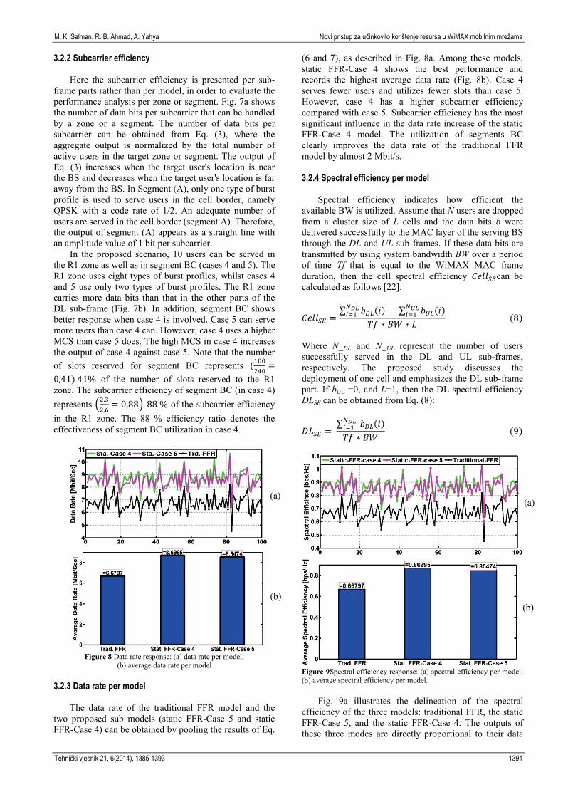
Figure 8 Data rate response: (a) data rate per model;
(b) average data rate per model 3.2.3 Data rate per model
The data rate of the traditional FFR model and the
two proposed sub models (static FFR-Case 5 and static FFR-Case 4) can be obtained by pooling the results of Eq.
(6 and 7), as described in Fig. 8a. Among these models, static FFR-Case 4 shows the best performance and records the highest average data rate (Fig. 8b). Case 4 serves fewer users and utilizes fewer slots than case 5. However, case 4 has a higher subcarrier efficiency compared with case 5. Subcarrier efficiency has the most significant influence in the data rate increase of the static FFR-Case 4 model. The utilization of segments BC clearly improves the data rate of the traditional FFR model by almost 2 Mbit/s. 3.2.4 Spectral efficiency per model
Spectral efficiency indicates how efficient the available BW is utilized. Assume that N users are dropped from a cluster size of L cells and the data bits b were delivered successfully to the MAC layer of the serving BS through the DL and UL sub-frames. If these data bits are transmitted by using system bandwidth BW over a period of time Tf that is equal to the WiMAX MAC frame duration, then the cell spectral efficiency 𝐶𝐶𝑒𝑒𝑒𝑒𝑒𝑒𝑆𝑆𝑆𝑆can be calculated as follows [22]:
𝐶𝐶𝑒𝑒𝑒𝑒𝑒𝑒𝑆𝑆𝑆𝑆 =∑ 𝑏𝑏𝐷𝐷𝐷𝐷(𝑖𝑖)𝑁𝑁𝐷𝐷𝐷𝐷𝑖𝑖=1 + ∑ 𝑏𝑏𝑈𝑈𝐷𝐷(𝑖𝑖)𝑁𝑁𝑈𝑈𝐷𝐷
𝑖𝑖=1𝑇𝑇𝑇𝑇 ∗ 𝐵𝐵𝐵𝐵 ∗ 𝐿𝐿
(8)
Where N_DL and N_UL represent the number of users successfully served in the DL and UL sub-frames, respectively. The proposed study discusses the deployment of one cell and emphasizes the DL sub-frame part. If bUL =0, and L=1, then the DL spectral efficiency DLSE can be obtained from Eq. (8):
𝐷𝐷𝐿𝐿𝑆𝑆𝑆𝑆 = ∑ 𝑏𝑏𝐷𝐷𝐷𝐷(𝑖𝑖)𝑁𝑁𝐷𝐷𝐷𝐷𝑖𝑖=1𝑇𝑇𝑇𝑇 ∗ 𝐵𝐵𝐵𝐵
(9)
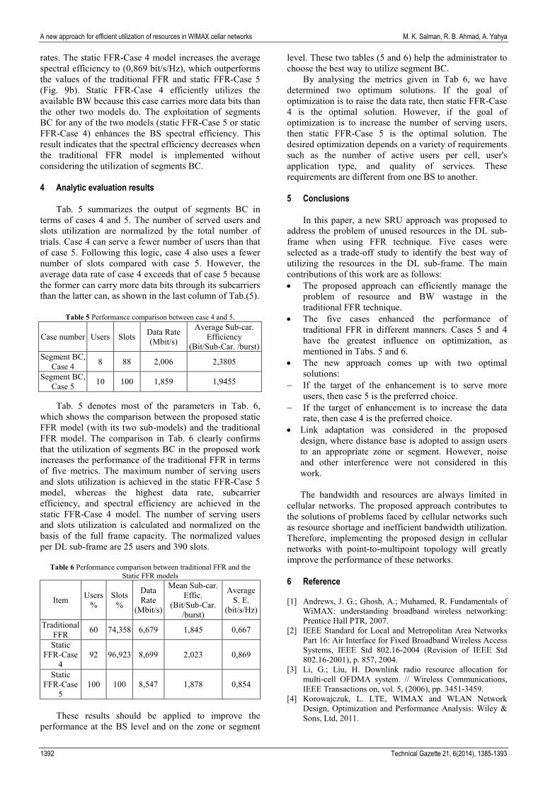
Figure 9Spectral efficiency response: (a) spectral efficiency per model; (b) average spectral efficiency per model.
Fig. 9a illustrates the delineation of the spectral efficiency of the three models: traditional FFR, the static FFR-Case 5, and the static FFR-Case 4. The outputs of these three modes are directly proportional to their data
(b)
(a) (a)
(b)
Tehnički vjesnik 21, 6(2014), 1385-1393 1391
A new approach for efficient utilization of resources in WIMAX cellar networks M. K. Salman, R. B. Ahmad, A. Yahya
rates. The static FFR-Case 4 model increases the average spectral efficiency to (0,869 bit/s/Hz), which outperforms the values of the traditional FFR and static FFR-Case 5 (Fig. 9b). Static FFR-Case 4 efficiently utilizes the available BW because this case carries more data bits than the other two models do. The exploitation of segments BC for any of the two models (static FFR-Case 5 or static FFR-Case 4) enhances the BS spectral efficiency. This result indicates that the spectral efficiency decreases when the traditional FFR model is implemented without considering the utilization of segments BC. 4 Analytic evaluation results
Tab. 5 summarizes the output of segments BC in
terms of cases 4 and 5. The number of served users and slots utilization are normalized by the total number of trials. Case 4 can serve a fewer number of users than that of case 5. Following this logic, case 4 also uses a fewer number of slots compared with case 5. However, the average data rate of case 4 exceeds that of case 5 because the former can carry more data bits through its subcarriers than the latter can, as shown in the last column of Tab.(5).
Table 5 Performance comparison between case 4 and 5.
Case number Users Slots Data Rate (Mbit/s)
Average Sub-car. Efficiency
(Bit/Sub-Car. /burst) Segment BC,
Case 4 8 88 2,006 2,3805
Segment BC, Case 5 10 100 1,859 1,9455
Tab. 5 denotes most of the parameters in Tab. 6,
which shows the comparison between the proposed static FFR model (with its two sub-models) and the traditional FFR model. The comparison in Tab. 6 clearly confirms that the utilization of segments BC in the proposed work increases the performance of the traditional FFR in terms of five metrics. The maximum number of serving users and slots utilization is achieved in the static FFR-Case 5 model, whereas the highest data rate, subcarrier efficiency, and spectral efficiency are achieved in the static FFR-Case 4 model. The number of serving users and slots utilization is calculated and normalized on the basis of the full frame capacity. The normalized values per DL sub-frame are 25 users and 390 slots.
Table 6 Performance comparison between traditional FFR and the Static FFR models
Item Users %
Slots %
Data Rate
(Mbit/s)
Mean Sub-car. Effic.
(Bit/Sub-Car. /burst)
Average S. E.
(bit/s/Hz)
Traditional FFR 60 74,358 6,679 1,845 0,667
Static FFR-Case
4 92 96,923 8,699 2,023 0,869
Static FFR-Case
5 100 100 8,547 1,878 0,854
These results should be applied to improve the
performance at the BS level and on the zone or segment
level. These two tables (5 and 6) help the administrator to choose the best way to utilize segment BC.
By analysing the metrics given in Tab 6, we have determined two optimum solutions. If the goal of optimization is to raise the data rate, then static FFR-Case 4 is the optimal solution. However, if the goal of optimization is to increase the number of serving users, then static FFR-Case 5 is the optimal solution. The desired optimization depends on a variety of requirements such as the number of active users per cell, user's application type, and quality of services. These requirements are different from one BS to another.
5 Conclusions
In this paper, a new SRU approach was proposed to address the problem of unused resources in the DL sub-frame when using FFR technique. Five cases were selected as a trade-off study to identify the best way of utilizing the resources in the DL sub-frame. The main contributions of this work are as follows: • The proposed approach can efficiently manage the
problem of resource and BW wastage in the traditional FFR technique.
• The five cases enhanced the performance of traditional FFR in different manners. Cases 5 and 4 have the greatest influence on optimization, as mentioned in Tabs. 5 and 6.
• The new approach comes up with two optimal solutions:
− If the target of the enhancement is to serve more users, then case 5 is the preferred choice.
− If the target of enhancement is to increase the data rate, then case 4 is the preferred choice.
• Link adaptation was considered in the proposed design, where distance base is adopted to assign users to an appropriate zone or segment. However, noise and other interference were not considered in this work. The bandwidth and resources are always limited in
cellular networks. The proposed approach contributes to the solutions of problems faced by cellular networks such as resource shortage and inefficient bandwidth utilization. Therefore, implementing the proposed design in cellular networks with point-to-multipoint topology will greatly improve the performance of these networks. 6 Reference [1] Andrews, J. G.; Ghosh, A.; Muhamed, R. Fundamentals of
WiMAX: understanding broadband wireless networking: Prentice Hall PTR, 2007.
[2] IEEE Standard for Local and Metropolitan Area Networks Part 16: Air Interface for Fixed Broadband Wireless Access Systems, IEEE Std 802.16-2004 (Revision of IEEE Std 802.16-2001), p. 857, 2004.
[3] Li, G.; Liu, H. Downlink radio resource allocation for multi-cell OFDMA system. // Wireless Communications, IEEE Transactions on, vol. 5, (2006), pp. 3451-3459.
[4] Korowajczuk, L. LTE, WIMAX and WLAN Network Design, Optimization and Performance Analysis: Wiley & Sons, Ltd, 2011.
1392 Technical Gazette 21, 6(2014), 1385-1393

M. K. Salman, R. B. Ahmad, A. Yahya Novi pristup za učinkovito korištenje resursa u WiMAX mobilnim mrežama
[5] WIMAX Forum, "Mobile WiMAX – Part 1: A Technical Overview and Performance Evaluation," p. 53, August, 2006.
[6] WIMAX Forum, "Mobile WiMAX – Part II: A Comparative Analysis," p. 47, May, 2006.
[7] Zhou, Y.; Zein, N. Simulation study of fractional frequency reuse for mobile WiMAX. // in Vehicular Technology Conference, 2008. VTC Spring 2008. IEEE, 2008, pp. 2592-2595.
[8] Jackson, J.; Roy, J.; Vaidehi, V. Analysis of Frequency Reuse and Throughput Enhancement in WiMAX Systems. // Wireless Personal Communications. 61, (2011), pp. 1-17.
[9] Ali-Yahiya, T.; Chaouchi, H. Fractional frequency reuse for hierarchical resource allocation in mobile WiMAX networks. // EURASIP Journal on Wireless Communications and Networking, (2010), p. 7.
[10] Stiakogiannakis, I. N.; Kaklamani, D. I. Fractional frequency reuse techniques for multi-cellular WiMAX networks. // in Personal Indoor and Mobile Radio Communications (PIMRC), 2010, IEEE 21st International Symposium on, 2010, pp. 2432-2437.
[11] Stiakogiannakis, I. N.; Athanasiadou, G. E.; Tsoulos, G. V.; Kaklamani, D. I. Performance Analysis of Fractional Frequency Reuse for Multi-Cell WiMAX Networks Based on Site-Specific Propagation Modeling [Wireless Corner]. // Antennas and Propagation Magazine, IEEE, 54, (2012), pp. 214-226.
[12] Giuliano, R.; Monti, C.; Loreti, P. WiMAX fractional frequency reuse for rural environments. // Wireless Communications, IEEE, 15, (2008), pp. 60-65.
[13] Pijcke, B.; Gazalet, M.; Zwinglestein-Colin, M.; Coudoux, F.-X. An accurate performance analysis of an FFR scheme in the downlink of cellular systems under large-shadowing effect. // EURASIP Journal on Wireless Communications and Networking, (2013), p. 48.
[14] Mohades, Z.; Tabataba Vakili, V.; Razavizadeh, S. M.; Abbasi-Moghadam, D. Dynamic Fractional Frequency Reuse (DFFR) with AMC and Random Access in WiMAX System. // Wireless Personal Communications, (2012), pp. 1-11.
[15] Chen, L.; Yuan, D. Generalizing and optimizing fractional frequency reuse in broadband cellular radio access networks. // EURASIP Journal on Wireless Communications and Networking, (2012), p. 230.
[16] Jia, H.; Zhang, Z.; Yu, G.; Cheng, P.; Li, S. On the performance of IEEE 802.16 OFDMA system under different frequency reuse and subcarrier permutation patterns. // in Communications, 2007. ICC'07. IEEE International Conference on, 2007, pp. 5720-5725.
[17] Han, S. S.; Tae-Jin, L.; Ahn, H. G. A new frequency partitioning and allocation of subcarriers for fractional frequency reuse in mobile communication systems. // IEICE transactions on communications, 91, (2008), pp. 2748-2751.
[18] Lee, C.-N.; Chen, Y.-T.; Kao, Y.-C.; Kao, H.-H.; Haga, S. Layered video multicast using fractional frequency reuse over wireless relay networks. // EURASIP Journal on Wireless Communications and Networking, (2012), p. 187.
[19] So-In, C.; Jain, R.; Tamimi, A.-K. Capacity evaluation for IEEE 802.16 e mobile WiMAX. // Journal of Computer Systems, Networks, and Communications, (2010), p. 1.
[20] Kumar, A. Mobile broadcasting with WiMAX: principles, technology, and applications: Taylor & Francis US, 2008.
[21] WIMAX Forum, "WiMAX System Evaluation Methodology," p. 209, July, 2008.
[22] Ahmadi, S. Mobile WiMAX: A systems approach to understanding IEEE 802.16m radio access technology: Academic Press, 2010.
Authors’ addresses Msc. Eng. M. K. Salman University Malaysia Perlis (UniMAP) Faculty of Computer and Communication Engineering Kuala Perlis, Perlis, 02000 – Malaysia E-mail: [email protected] Prof. Dr. Eng. R. B. Ahmad University Malaysia Perlis (UniMAP) Dean /Faculty Computer and Communication Engineering Kuala Perlis, Perlis, 02000 – Malaysia E-mail: [email protected] Dr. Eng. Abid Yahya University Malaysia Perlis (UniMAP) Faculty of Computer and Communication Engineering Kuala Perlis, Perlis, 02000 – Malaysia E-mail: [email protected]
Tehnički vjesnik 21, 6(2014), 1385-1393 1393


![HIRİSTİYAN OLAN BİR MÜSLÜMAN · Web view[Asıl adı Muhammed Şükrü Efendi olan] YAHYA AVETARANYAN’IN YAŞAM ÖYKÜSÜ. Yahya Avetaranyan tarafından yazılan. Geschichte](https://static.fdocuments.nl/doc/165x107/5e5bc48b05af156ef53592d5/hirstyan-olan-br-moesloeman-web-view-asl-ad-muhammed-kr-efendi.jpg)