LancerX SRS
26
52B-1 GROUP 52B SUPPLEMENTAL RESTRAINT SYSTEM (SRS) CONTENTS GENERAL INFORMATION . . . . . . . . 52B-2 SYSTEM OPERATION. . . . . . . . . . . . 52B-10 ADVANCED AIR BAG AND SEAT BELT WITH PRE-TENSIONER. . . . . . . . . . . . . . . . . . . . 52B-10 SIDE AND CURTAIN AIR BAGS . . . . . . . . 52B-11 SYSTEM CONSTRUCTION . . . . . . . . 52B-11 DRIVER'S SIDE AIR BAG MODULE . . . . . 52B-11 CLOCK SPRING . . . . . . . . . . . . . . . . . . . . . 52B-12 PASSENGER'S (FRONT) AIR BAG MODULE . . . . . . . . . . . . . . . . . . . . . . . . . . . 52B-12 KNEE AIR BAG MODULE . . . . . . . . . . . . . 52B-13 SIDE-AIRBAG MODULE . . . . . . . . . . . . . . . 52B-13 CURTAIN AIR BAG MODULE. . . . . . . . . . . 52B-14 FRONT IMPACT SENSOR . . . . . . . . . . . . . 52B-14 SIDE IMPACT SENSOR . . . . . . . . . . . . . . . 52B-14 SEAT SLIDE SENSOR . . . . . . . . . . . . . . . . 52B-15 OCCUPANT CLASSIFICATION-ECU AND WEIGHT SENSOR . . . . . . . . . . . . . . . . . . . 52B-15 SEAT BELT WITH PRE-TENSIONER. . . . . 52B-18 PASSENGER SEAT BELT WARNING LIGHT . . . . . . . . . . . . . . . . . . . . . . . . . . . . . 52B-20 PASSENGER'S AIR BAG OFF INDICATOR LIGHT . . . . . . . . . . . . . . . . . . . . . . . . . . . . . 52B-20 SRS-ECU . . . . . . . . . . . . . . . . . . . . . . . . . . 52B-21 SRS AIR BAG SPECIAL CONNECTOR . . . 52B-25
-
Upload
emr-moncan -
Category
Documents
-
view
217 -
download
0
Transcript of LancerX SRS
8/19/2019 LancerX SRS
http://slidepdf.com/reader/full/lancerx-srs 1/26
52B-1
GROUP 52B
SUPPLEMENTALRESTRAINTSYSTEM (SRS)
CONTENTS
GENERAL INFORMATION . . . . . . . . 52B-2
SYSTEM OPERATION. . . . . . . . . . . . 52B-10
ADVANCED AIR BAG AND SEAT BELT WITH
PRE-TENSIONER. . . . . . . . . . . . . . . . . . . . 52B-10
SIDE AND CURTAIN AIR BAGS . . . . . . . . 52B-11
SYSTEM CONSTRUCTION. . . . . . . . 52B-11
DRIVER'S SIDE AIR BAG MODULE . . . . . 52B-11
CLOCK SPRING. . . . . . . . . . . . . . . . . . . . . 52B-12
PASSENGER'S (FRONT) AIR BAG
MODULE. . . . . . . . . . . . . . . . . . . . . . . . . . . 52B-12
KNEE AIR BAG MODULE . . . . . . . . . . . . . 52B-13
SIDE-AIRBAG MODULE . . . . . . . . . . . . . . . 52B-13
CURTAIN AIR BAG MODULE. . . . . . . . . . . 52B-14
FRONT IMPACT SENSOR . . . . . . . . . . . . . 52B-14
SIDE IMPACT SENSOR . . . . . . . . . . . . . . . 52B-14
SEAT SLIDE SENSOR . . . . . . . . . . . . . . . . 52B-15
OCCUPANT CLASSIFICATION-ECU AND
WEIGHT SENSOR . . . . . . . . . . . . . . . . . . . 52B-15
SEAT BELT WITH PRE-TENSIONER. . . . . 52B-18
PASSENGER SEAT BELT WARNING
LIGHT . . . . . . . . . . . . . . . . . . . . . . . . . . . . . 52B-20
PASSENGER'S AIR BAG OFF INDICATOR
LIGHT . . . . . . . . . . . . . . . . . . . . . . . . . . . . . 52B-20
SRS-ECU . . . . . . . . . . . . . . . . . . . . . . . . . . 52B-21
SRS AIR BAG SPECIAL CONNECTOR . . . 52B-25
8/19/2019 LancerX SRS
http://slidepdf.com/reader/full/lancerx-srs 2/26
GENERAL INFORMATION
SUPPLEMENTAL RESTRAINT SYSTEM (SRS)52B-2
GENERAL INFORMATIONM2521000100994
CAUTION
• Driver and passenger’s (front) air bags, knee
air bag and seat belt pre-tensioner deploy and
operate in frontal collisions that exceed the
threshold to activate the SRS (Supplemental
Restraint System).
• The front air bag deploys when a vehicle col-
lides head-on with a concrete (fixed) wall at
approximately 25 km/h (15 mph) or more, or
when a vehicle suffers a severe impact from
the front side.The side air bag deploys when a
center of side body suffers a severe impact.
• The front air bags and pre-tensioner may not
work under the following conditions:
• A frontal collision is less than the specific
value.
• The collision is from the rear • The collision is from the side
• The vehicle rolls over or is in a similar
position.
• The side-airbags and curtain air bags may not
work under the following conditions:
• The collision is from the front
• The collision is from the rear
• Driver's and passenger's (front) air bags, side-air-
bags, knee air bag, curtain air bags and seat
belts with pre-tensioner have been installed to all
the vehicles as standard.• The SRS is a system that is effective with the
seat belt fastened, and it is designed as a supple-
mental system of the seat belt.
• The advanced air bag system has been adopted
to the driver's and passenger's (front) sides.
When a frontal impact exceeds the threshold
upon a frontal collision, or depending on the seat
position (driver's seat side), the air bag inflates
the cushion air bag in two stages, improving theprotection for the front seat passengers.
• When a frontal impact exceeds the threshold, the
knee air bag is instantaneously inflated to protect
the passenger's feet (knee and leg).
• The side-airbag is activated when an impact
exceeds the threshold upon a side collision, and
the cushion air bag is instantaneously inflated to
protect the chest area of the front seat passen-
gers.
• The curtain air bag is activated simultaneously
with the side-airbag upon a side collision to pro-
tect the heads of the front seat and second seatpassengers.
• All the air bag modules are equipped with the
inflator that does not contain toxic sodium azide.
• The seat belt pre-tensioner is activated simulta-
neously with the deployment of driver's and pas-
senger's (front) air bags in case of a frontal
collision. Seat belts are pulled in to eliminate the
slack upon a collision, thus improving the initial
occupant restraint, and reducing the travel dis-
tance of the occupants. For the driver's seat, in
addition to the seat belt pre-tensioner for the
shoulder side, the lap pre-tensioner has been
installed on the outer seat belt lower anchor side
in order to improve the restraining performance in
the waist and the chest areas.
8/19/2019 LancerX SRS
http://slidepdf.com/reader/full/lancerx-srs 3/26
GENERAL INFORMATION
SUPPLEMENTAL RESTRAINT SYSTEM (SRS) 52B-3
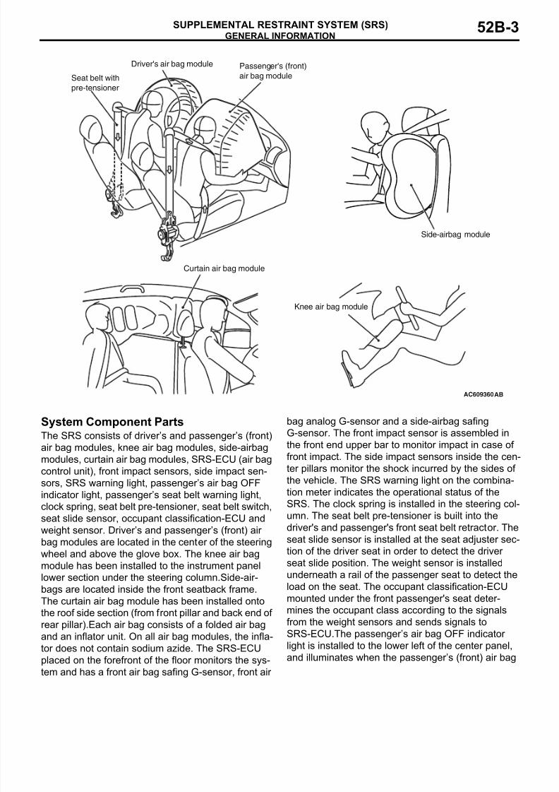
System Component PartsThe SRS consists of driver’s and passenger’s (front)
air bag modules, knee air bag modules, side-airbag
modules, curtain air bag modules, SRS-ECU (air bag
control unit), front impact sensors, side impact sen-
sors, SRS warning light, passenger’s air bag OFF
indicator light, passenger’s seat belt warning light,
clock spring, seat belt pre-tensioner, seat belt switch,
seat slide sensor, occupant classification-ECU and
weight sensor. Driver’s and passenger’s (front) air
bag modules are located in the center of the steering
wheel and above the glove box. The knee air bagmodule has been installed to the instrument panel
lower section under the steering column.Side-air-
bags are located inside the front seatback frame.
The curtain air bag module has been installed onto
the roof side section (from front pillar and back end of
rear pillar).Each air bag consists of a folded air bag
and an inflator unit. On all air bag modules, the infla-
tor does not contain sodium azide. The SRS-ECU
placed on the forefront of the floor monitors the sys-
tem and has a front air bag safing G-sensor, front air
bag analog G-sensor and a side-airbag safing
G-sensor. The front impact sensor is assembled in
the front end upper bar to monitor impact in case of
front impact. The side impact sensors inside the cen-
ter pillars monitor the shock incurred by the sides of
the vehicle. The SRS warning light on the combina-
tion meter indicates the operational status of the
SRS. The clock spring is installed in the steering col-
umn. The seat belt pre-tensioner is built into the
driver's and passenger's front seat belt retractor. The
seat slide sensor is installed at the seat adjuster sec-
tion of the driver seat in order to detect the driverseat slide position. The weight sensor is installed
underneath a rail of the passenger seat to detect the
load on the seat. The occupant classification-ECU
mounted under the front passenger's seat deter-
mines the occupant class according to the signals
from the weight sensors and sends signals to
SRS-ECU.The passenger’s air bag OFF indicator
light is installed to the lower left of the center panel,
and illuminates when the passenger’s (front) air bag
AC609360
Driver's air bag module Passenger's (front)
air bag module
Side-airbag module
Curtain air bag module
Seat belt with
pre-tensioner
AB
Knee air bag module
8/19/2019 LancerX SRS
http://slidepdf.com/reader/full/lancerx-srs 4/26
GENERAL INFORMATION
SUPPLEMENTAL RESTRAINT SYSTEM (SRS)52B-4
is inactive. The passenger’s seat belt warning light is
installed to the lower right of the center panel, and
illuminates when the passenger is not wearing the
seat belt. The seat belt switch detects whether the
seat belt is used.
The SRS-ECU will start a squib ignition current to the
driver's/passenger’s (front) air bag module, knee air
bag module and seat belt pre-tensioner when simul-taneously detecting frontal impact with the front
impact sensor, front air bag safing G-sensor and
front air bag analog G-sensor. It will also supply a
squib ignition current to the side-airbag module and
curtain air bag module when simultaneously detect-
ing side impact with the side impact sensor and
side-airbag safing G-sensor.
8/19/2019 LancerX SRS
http://slidepdf.com/reader/full/lancerx-srs 5/26
GENERAL INFORMATION
SUPPLEMENTAL RESTRAINT SYSTEM (SRS) 52B-5
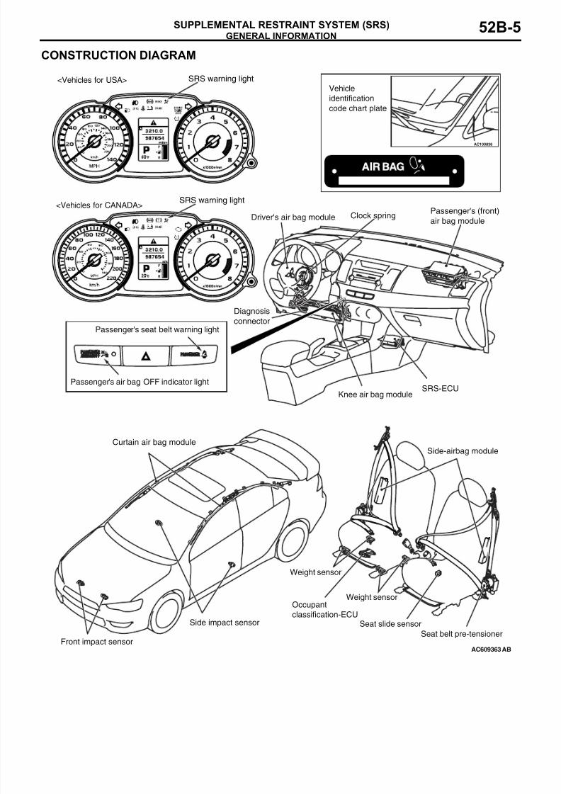
CONSTRUCTION DIAGRAM
AC609363
AC100836
Curtain air bag module
Side impact sensor
Side-airbag module
Front impact sensor
SRS-ECU
Driver's air bag module Clock springPassenger's (front)
air bag module
Diagnosis
connector
AB
SRS warning light
SRS warning light
<Vehicles for USA>
<Vehicles for CANADA>
Knee air bag module
Seat belt pre-tensioner
Occupant
classification-ECUSeat slide sensor
Weight sensor
Passenger's seat belt warning light
Passenger's air bag OFF indicator light
Vehicle
identification
code chart plate
Weight sensor
8/19/2019 LancerX SRS
http://slidepdf.com/reader/full/lancerx-srs 6/26
GENERAL INFORMATION
SUPPLEMENTAL RESTRAINT SYSTEM (SRS)52B-6
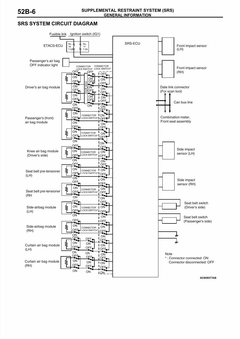
SRS SYSTEM CIRCUIT DIAGRAM
AC609377
ONOFF
OFF
OFF
ON ON
ON
OFF
ON
OFF
ON
OFF
ONOFF
OFF
OFF
ONON
ON
OFF
ON
OFF
ON
OFF
*
OFF
ONOFF
ON
ON
OFF
ON
OFF
OFF
ON
OFF
ON
ON
OFFON
OFF
OFF
ON
OFF
ONOFF
ON
OFF
ON
ON
OFF
ON
OFF
ON
OFF
ON
OFF
ONOFF
ON
OFF
ON
OFF
ON
OFF
ON
ON
OFF
ON
OFF
ON
OFF
ON
OFF
OFF
ONOFF
ON
OFF
ON
OFF
ON
OFF
ON
OFF
ON
OFF
ON
OFF
ONOFF
ON
OFF
ON
OFF
ON
OFF
C l o c k s pr i n g
Driver's air bag module
Passenger's (front)air bag module
Side-airbag module
(LH)
Side-airbag module
(RH)
Seat belt pre-tensioner
(RH
Seat belt pre-tensioner
(LH)
Knee air bag module
(Driver's side)
Curtain air bag module
(LH)
Curtain air bag module
(RH)
ON
OFF
ON
OFF
ON
OFF
ON
OFF
No.187.5A
No.127.5A
ETACS-ECUSRS-ECU
Ignition switch (IG1)
Front impact sensor
(RH)
Front impact sensor(LH)
Side impact
sensor (LH)
Side impact
sensor (RH)
AB
Note
* : Connector connected: ON
Connector disconnected: OFF
Date link connector
(For scan tool)
Can bus line
Combination meter,Front seat assembly
Seat belt switch
(Driver's side)
Seat belt switch
(Passenger's side)
Fusible link
CONNECTORLOCK SWITCH*
CONNECTORLOCK SWITCH*
CONNECTORLOCK SWITCH*
CONNECTORLOCK SWITCH*
CONNECTORLOCK SWITCH*
CONNECTORLOCK SWITCH*
CONNECTOR
LOCK SWITCH*
CONNECTORLOCK SWITCH*
CONNECTORLOCK SWITCH*
Passenger's air bag
OFF indicator light
8/19/2019 LancerX SRS
http://slidepdf.com/reader/full/lancerx-srs 7/26
GENERAL INFORMATION
SUPPLEMENTAL RESTRAINT SYSTEM (SRS) 52B-7
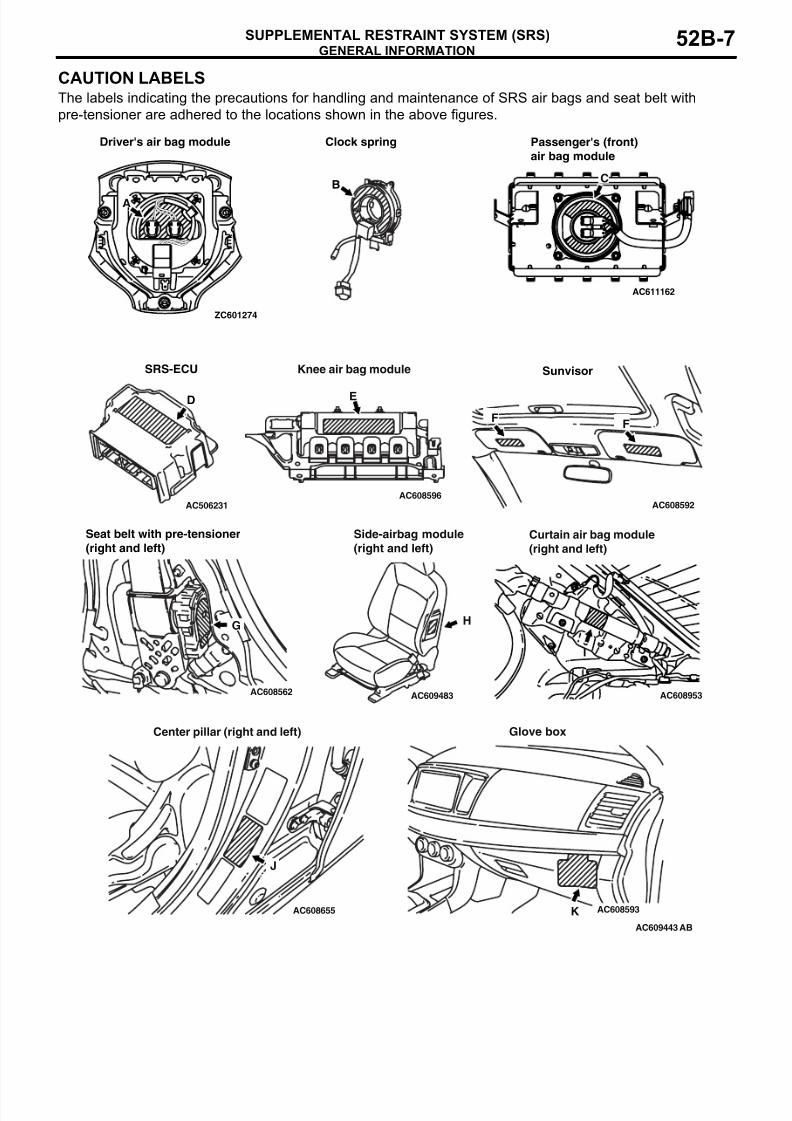
CAUTION LABELSThe labels indicating the precautions for handling and maintenance of SRS air bags and seat belt with
pre-tensioner are adhered to the locations shown in the above figures.
ZC601274
AC609443
AC506231
AC608562
AC608596
AC608655 AC608593
AC608592
AC608953AC609483
AC611162
Driver's air bag module Clock spring
Sunvisor
Seat belt with pre-tensioner
(right and left)
D
B
SRS-ECU
Passenger's (front)
air bag module
A
E
F
I
Curtain air bag module
(right and left)
H
J
K
Glove box
AB
Knee air bag module
F
G
Side-airbag module
(right and left)
Center pillar (right and left)
C
8/19/2019 LancerX SRS
http://slidepdf.com/reader/full/lancerx-srs 8/26
GENERAL INFORMATION
SUPPLEMENTAL RESTRAINT SYSTEM (SRS)52B-8
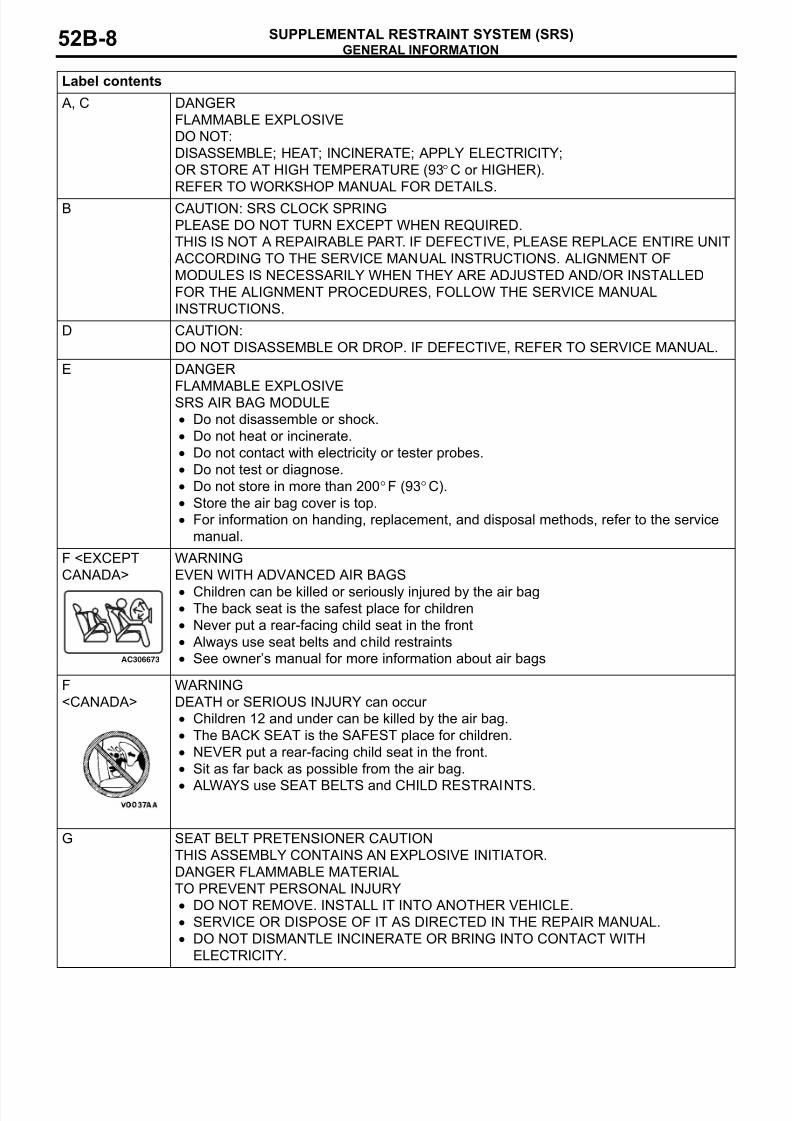
Label contents
A, C DANGER
FLAMMABLE EXPLOSIVE
DO NOT:
DISASSEMBLE; HEAT; INCINERATE; APPLY ELECTRICITY;
OR STORE AT HIGH TEMPERATURE (93°C or HIGHER).
REFER TO WORKSHOP MANUAL FOR DETAILS.
B CAUTION: SRS CLOCK SPRING
PLEASE DO NOT TURN EXCEPT WHEN REQUIRED.
THIS IS NOT A REPAIRABLE PART. IF DEFECTIVE, PLEASE REPLACE ENTIRE UNIT
ACCORDING TO THE SERVICE MANUAL INSTRUCTIONS. ALIGNMENT OF
MODULES IS NECESSARILY WHEN THEY ARE ADJUSTED AND/OR INSTALLED
FOR THE ALIGNMENT PROCEDURES, FOLLOW THE SERVICE MANUAL
INSTRUCTIONS.
D CAUTION:
DO NOT DISASSEMBLE OR DROP. IF DEFECTIVE, REFER TO SERVICE MANUAL.
E DANGER
FLAMMABLE EXPLOSIVESRS AIR BAG MODULE
• Do not disassemble or shock.
• Do not heat or incinerate.
• Do not contact with electricity or tester probes.
• Do not test or diagnose.
• Do not store in more than 200°F (93°C).
• Store the air bag cover is top.
• For information on handing, replacement, and disposal methods, refer to the service
manual.
F <EXCEPT
CANADA>
WARNING
EVEN WITH ADVANCED AIR BAGS
• Children can be killed or seriously injured by the air bag• The back seat is the safest place for children
• Never put a rear-facing child seat in the front
• Always use seat belts and child restraints
• See owner’s manual for more information about air bags
F
<CANADA>
WARNING
DEATH or SERIOUS INJURY can occur
• Children 12 and under can be killed by the air bag.
• The BACK SEAT is the SAFEST place for children.
• NEVER put a rear-facing child seat in the front.
• Sit as far back as possible from the air bag.
• ALWAYS use SEAT BELTS and CHILD RESTRAINTS.
G SEAT BELT PRETENSIONER CAUTION
THIS ASSEMBLY CONTAINS AN EXPLOSIVE INITIATOR.
DANGER FLAMMABLE MATERIAL
TO PREVENT PERSONAL INJURY
• DO NOT REMOVE. INSTALL IT INTO ANOTHER VEHICLE.
• SERVICE OR DISPOSE OF IT AS DIRECTED IN THE REPAIR MANUAL.
• DO NOT DISMANTLE INCINERATE OR BRING INTO CONTACT WITH
ELECTRICITY.
AC306673
8/19/2019 LancerX SRS
http://slidepdf.com/reader/full/lancerx-srs 9/26
GENERAL INFORMATION
SUPPLEMENTAL RESTRAINT SYSTEM (SRS) 52B-9
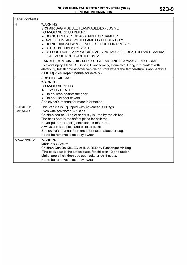
H WARNING
SRS AIR BAG MODULE FLAMMABLE/EXPLOSIVE
TO AVOID SERIOUS INJURY:
• DO NOT REPAIR, DISASSEMBLE OR TAMPER.
• AVOID CONTACT WITH FLAME OR ELECTRICITY.
• DO NO DIAGNOSIS/USE NO TEST EQPT OR PROBES.
• STORE BELOW 200°F (93°C).
• BEFORE DOING ANY WORK INVOLVING MODULE, READ SERVICE MANUAL
FOR IMPORTANT FURTHER DATA.
I DANGER CONTAINS HIGH-PRESSURE GAS AND FLAMMABLE MATERIAL
To avoid injury, NEVER; [Repair, Disassembly, Incinerate, Bring into contact with
electricity, Install onto another vehicle or Store where the temperature is above 93°C
(200°F)] -See Repair Manual for details.-
J SRS SIDE AIRBAG
WARNING
TO AVOID SERIOUS
INJURY OR DEATH:
• Do not lean against the door.• Do not use seat covers.
See owner’s manual for more information
K <EXCEPT
CANADA>
This Vehicle is Equipped with Advanced Air Bags
Even with Advanced Air Bags
Children can be killed or seriously injured by the air bag.
The back seat is the safest place for children.
Never put a rear-facing child seat in the front.
Always use seat belts and child restraints.
See owner’s manual for more information about air bags.
Not to be removed except by owner.
K <CANADA> WARNINGMISE EN GARDE
Children Can Be KILLED or INJURED by Passenger Air Bag
The back seat is the safest place for children 12 and under.
Make sure all children use seat belts or child seats.
Not to be removed except by owner.
Label contents
8/19/2019 LancerX SRS
http://slidepdf.com/reader/full/lancerx-srs 10/26
SYSTEM OPERATION
SUPPLEMENTAL RESTRAINT SYSTEM (SRS)52B-10
SYSTEM OPERATION
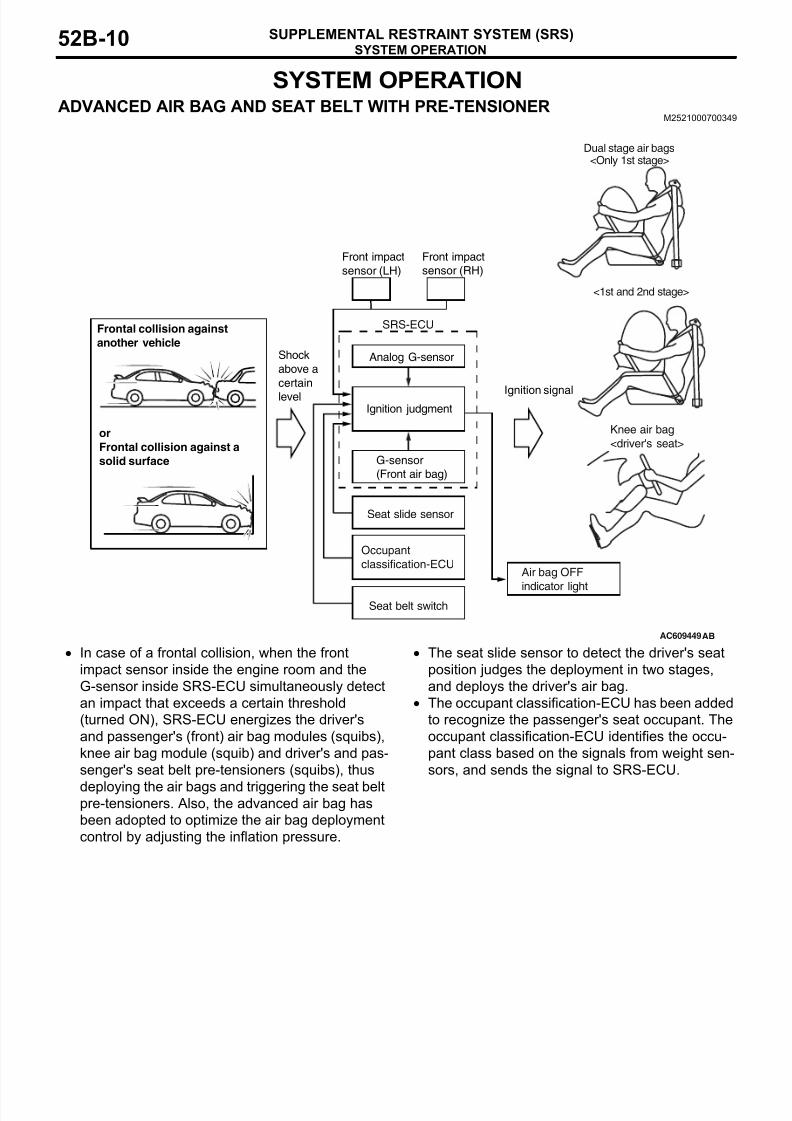
ADVANCED AIR BAG AND SEAT BELT WITH PRE-TENSIONERM2521000700349
• In case of a frontal collision, when the front
impact sensor inside the engine room and the
G-sensor inside SRS-ECU simultaneously detect
an impact that exceeds a certain threshold
(turned ON), SRS-ECU energizes the driver's
and passenger's (front) air bag modules (squibs),
knee air bag module (squib) and driver's and pas-
senger's seat belt pre-tensioners (squibs), thus
deploying the air bags and triggering the seat beltpre-tensioners. Also, the advanced air bag has
been adopted to optimize the air bag deployment
control by adjusting the inflation pressure.
• The seat slide sensor to detect the driver's seat
position judges the deployment in two stages,
and deploys the driver's air bag.
• The occupant classification-ECU has been added
to recognize the passenger's seat occupant. The
occupant classification-ECU identifies the occu-
pant class based on the signals from weight sen-
sors, and sends the signal to SRS-ECU.
AC609449
G-sensor
(Front air bag)
Shock
above a
certain
level Ignition signal
Frontal collision against
another vehicle
or
Frontal collision against a
solid surface
Front impact
sensor (LH)
Front impact
sensor (RH)
Ignition judgment
SRS-ECU
Dual stage air bags<Only 1st stage>
<1st and 2nd stage>
Knee air bag
<driver's seat>
Seat belt switch
Air bag OFF
indicator light
Occupant
classification-ECU
AB
Seat slide sensor
Analog G-sensor
8/19/2019 LancerX SRS
http://slidepdf.com/reader/full/lancerx-srs 11/26
SYSTEM CONSTRUCTION
SUPPLEMENTAL RESTRAINT SYSTEM (SRS) 52B-11
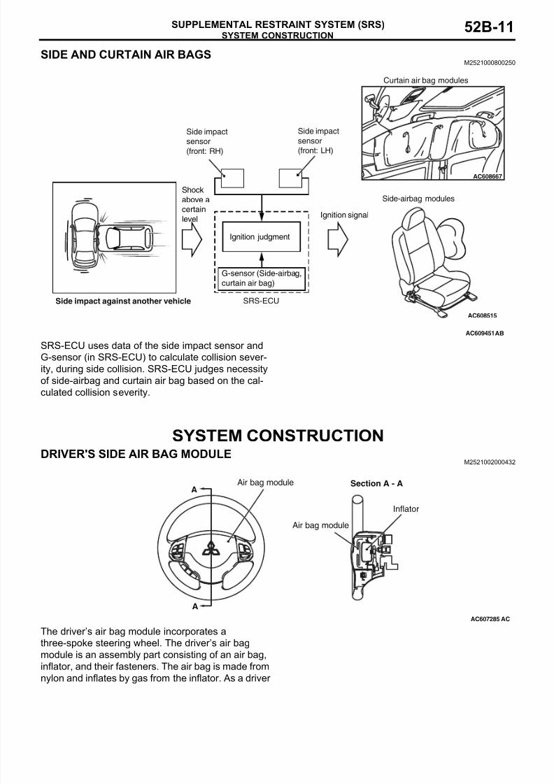
SIDE AND CURTAIN AIR BAGSM2521000800250
SRS-ECU uses data of the side impact sensor and
G-sensor (in SRS-ECU) to calculate collision sever-
ity, during side collision. SRS-ECU judges necessity
of side-airbag and curtain air bag based on the cal-
culated collision severity.
SYSTEM CONSTRUCTION
DRIVER'S SIDE AIR BAG MODULEM2521002000432
The driver’s air bag module incorporates a
three-spoke steering wheel. The driver’s air bag
module is an assembly part consisting of an air bag,
inflator, and their fasteners. The air bag is made from
nylon and inflates by gas from the inflator. As a driver
AC609451
AC608667
AC608515
Side impact
sensor
(front: RH)
Side impact
sensor
(front: LH)
Shock
above a
certain
levelIgnition signal
Ignition judgment
G-sensor (Side-airbag,curtain air bag)
SRS-ECU
Curtain air bag modules
Side-airbag modules
AB
Side impact against another vehicle
AC607285
A
A
Air bag module Section A - A
Inflator
Air bag module
AC
8/19/2019 LancerX SRS
http://slidepdf.com/reader/full/lancerx-srs 12/26
SYSTEM CONSTRUCTION
SUPPLEMENTAL RESTRAINT SYSTEM (SRS)52B-12
is being pressed to the air bag, it deflates discharg-
ing gas from two vents at the rear of the air bag to
reduce the shock from the impact. The driver's air
bag deploys by changing its inflation pressure in two
steps. The inflator has two squib connectors to
deploy the air bag in two steps. The inflator does not
contain sodium azide.
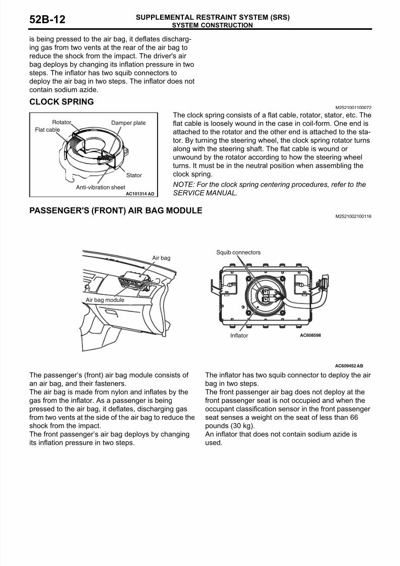
CLOCK SPRINGM2521001100072
The clock spring consists of a flat cable, rotator, stator, etc. The
flat cable is loosely wound in the case in coil-form. One end is
attached to the rotator and the other end is attached to the sta-
tor. By turning the steering wheel, the clock spring rotator turns
along with the steering shaft. The flat cable is wound or
unwound by the rotator according to how the steering wheel
turns. It must be in the neutral position when assembling the
clock spring.
NOTE: For the clock spring centering procedures, refer to the
SERVICE MANUAL.
PASSENGER'S (FRONT) AIR BAG MODULEM2521002100116
The passenger’s (front) air bag module consists of
an air bag, and their fasteners.
The air bag is made from nylon and inflates by the
gas from the inflator. As a passenger is being
pressed to the air bag, it deflates, discharging gas
from two vents at the side of the air bag to reduce the
shock from the impact.
The front passenger’s air bag deploys by changing
its inflation pressure in two steps.
The inflator has two squib connector to deploy the air
bag in two steps.
The front passenger air bag does not deploy at the
front passenger seat is not occupied and when the
occupant classification sensor in the front passenger
seat senses a weight on the seat of less than 66
pounds (30 kg).
An inflator that does not contain sodium azide is
used.
AC101314
Rotator
Flat cableDamper plate
Stator
Anti-vibration sheetAD
AC609452
AC608598
Air bag module
Air bagSquib connectors
Inflator
AB
8/19/2019 LancerX SRS
http://slidepdf.com/reader/full/lancerx-srs 13/26
SYSTEM CONSTRUCTION
SUPPLEMENTAL RESTRAINT SYSTEM (SRS) 52B-13
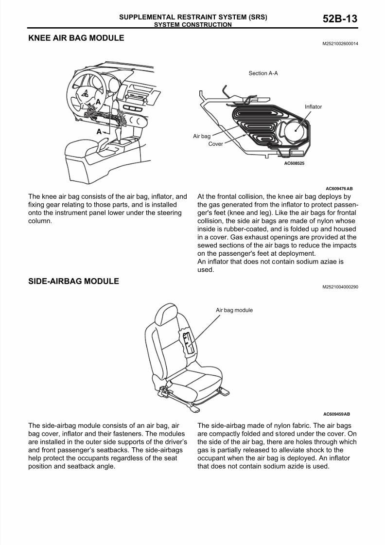
KNEE AIR BAG MODULEM2521002600014
The knee air bag consists of the air bag, inflator, and
fixing gear relating to those parts, and is installed
onto the instrument panel lower under the steering
column.
At the frontal collision, the knee air bag deploys by
the gas generated from the inflator to protect passen-
ger's feet (knee and leg). Like the air bags for frontal
collision, the side air bags are made of nylon whose
inside is rubber-coated, and is folded up and housed
in a cover. Gas exhaust openings are provided at the
sewed sections of the air bags to reduce the impacts
on the passenger's feet at deployment.
An inflator that does not contain sodium aziae is
used.
SIDE-AIRBAG MODULEM2521004000290
The side-airbag module consists of an air bag, air
bag cover, inflator and their fasteners. The modules
are installed in the outer side supports of the driver’s
and front passenger’s seatbacks. The side-airbags
help protect the occupants regardless of the seat
position and seatback angle.
The side-airbag made of nylon fabric. The air bags
are compactly folded and stored under the cover. On
the side of the air bag, there are holes through which
gas is partially released to alleviate shock to the
occupant when the air bag is deployed. An inflator
that does not contain sodium azide is used.
AC609476
AC608525
AB
Section A-A
A
AInflator
Air bag
Cover
AC609459
Air bag module
AB
8/19/2019 LancerX SRS
http://slidepdf.com/reader/full/lancerx-srs 14/26
SYSTEM CONSTRUCTION
SUPPLEMENTAL RESTRAINT SYSTEM (SRS)52B-14
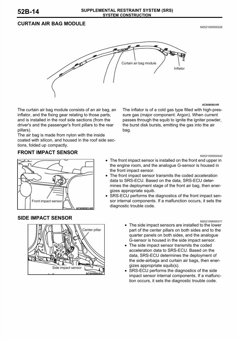
CURTAIN AIR BAG MODULEM2521000500226
The curtain air bag module consists of an air bag, an
inflator, and the fixing gear relating to those parts,
and is installed in the roof side sections (from thedriver's and the passenger's front pillars to the rear
pillars).
The air bag is made from nylon with the inside
coated with silicon, and housed in the roof side sec-
tions, folded up compactly.
The inflator is of a cold gas type filled with high-pres-
sure gas (major component: Argon). When current
passes through the squib to ignite the igniter powder,the burst disk bursts, emitting the gas into the air
bag.
FRONT IMPACT SENSORM2521005000442
• The front impact sensor is installed on the front end upper in
the engine room, and the analogue G-sensor is housed in
the front impact sensor.
• The front impact sensor transmits the coded acceleration
data to SRS-ECU. Based on the data, SRS-ECU deter-
mines the deployment stage of the front air bag, then ener-
gizes appropriate squib.
• SRS-ECU performs the diagnostics of the front impact sen-
sor internal components. If a malfunction occurs, it sets the
diagnostic trouble code.
SIDE IMPACT SENSORM2521006000371
• The side impact sensors are installed to the lower
part of the center pillars on both sides and to the
quarter panels on both sides, and the analogue
G-sensor is housed in the side impact sensor.
• The side impact sensor transmits the coded
acceleration data to SRS-ECU. Based on the
data, SRS-ECU determines the deployment of
the side-airbags and curtain air bags, then ener-
gizes appropriate squib(s).
• SRS-ECU performs the diagnostics of the side
impact sensor internal components. If a malfunc-
tion occurs, it sets the diagnostic trouble code.
AC608585
Curtain air bag module
Inflator
AB
AC608583
Front impact sensor
AB
AC605684
Center pillar
AD
Side impact sensor
8/19/2019 LancerX SRS
http://slidepdf.com/reader/full/lancerx-srs 15/26
SYSTEM CONSTRUCTION
SUPPLEMENTAL RESTRAINT SYSTEM (SRS) 52B-15
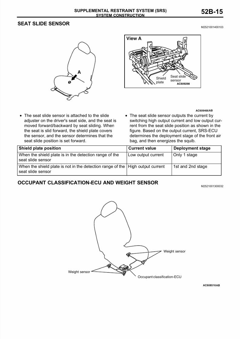
SEAT SLIDE SENSORM2521001400103
• The seat slide sensor is attached to the slide
adjuster on the driver's seat side, and the seat is
moved forward/backward by seat sliding. When
the seat is slid forward, the shield plate covers
the sensor, and the sensor determines that the
seat slide position is set forward.
• The seat slide sensor outputs the current by
switching high output current and low output cur-
rent from the seat slide position as shown in the
figure. Based on the output current, SRS-ECU
determines the deployment stage of the front air
bag, and then energizes the squib.
OCCUPANT CLASSIFICATION-ECU AND WEIGHT SENSORM2521001300032
AC609466
AC609298
ASeat slidesensor
Shieldplate
View A
AB
Shield plate position Current value Deployment stage
When the shield plate is in the detection range of the
seat slide sensor
Low output current Only 1 stage
When the shield plate is not in the detection range of the
seat slide sensor
High output current 1st and 2nd stage
AC608516
Weight sensor
Weight sensor
Occupant classification-ECU
AB
8/19/2019 LancerX SRS
http://slidepdf.com/reader/full/lancerx-srs 16/26
SYSTEM CONSTRUCTION
SUPPLEMENTAL RESTRAINT SYSTEM (SRS)52B-16
The weight sensors are attached to the seat rails and
provide SRS-ECU with information on the weight
applied to the front passenger seat.
The occupant classification-ECU identifies the occu-
pant class based on the signals from weight sensors,
and sends the signal to SRS-ECU. When the occu-
pant is determined to be less than 66 lbs (30 kg), the
passenger's (front) air bag is not deployed.
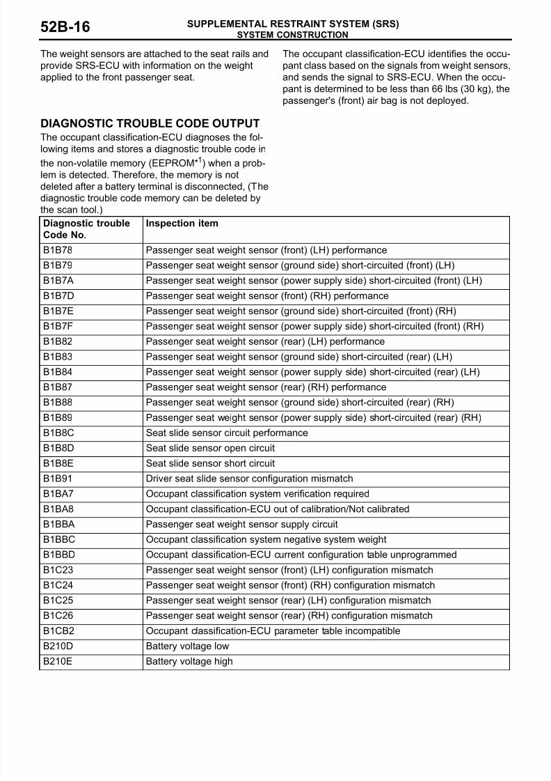
DIAGNOSTIC TROUBLE CODE OUTPUT
The occupant classification-ECU diagnoses the fol-lowing items and stores a diagnostic trouble code in
the non-volatile memory (EEPROM*1) when a prob-
lem is detected. Therefore, the memory is not
deleted after a battery terminal is disconnected, (The
diagnostic trouble code memory can be deleted by
the scan tool.)
Diagnostic trouble
Code No.
Inspection item
B1B78 Passenger seat weight sensor (front) (LH) performance
B1B79 Passenger seat weight sensor (ground side) short-circuited (front) (LH)
B1B7A Passenger seat weight sensor (power supply side) short-circuited (front) (LH)
B1B7D Passenger seat weight sensor (front) (RH) performance
B1B7E Passenger seat weight sensor (ground side) short-circuited (front) (RH)
B1B7F Passenger seat weight sensor (power supply side) short-circuited (front) (RH)
B1B82 Passenger seat weight sensor (rear) (LH) performance
B1B83 Passenger seat weight sensor (ground side) short-circuited (rear) (LH)
B1B84 Passenger seat weight sensor (power supply side) short-circuited (rear) (LH)
B1B87 Passenger seat weight sensor (rear) (RH) performance
B1B88 Passenger seat weight sensor (ground side) short-circuited (rear) (RH)
B1B89 Passenger seat weight sensor (power supply side) short-circuited (rear) (RH)
B1B8C Seat slide sensor circuit performance
B1B8D Seat slide sensor open circuit
B1B8E Seat slide sensor short circuit
B1B91 Driver seat slide sensor configuration mismatch
B1BA7 Occupant classification system verification required
B1BA8 Occupant classification-ECU out of calibration/Not calibrated
B1BBA Passenger seat weight sensor supply circuit
B1BBC Occupant classification system negative system weight
B1BBD Occupant classification-ECU current configuration table unprogrammed
B1C23 Passenger seat weight sensor (front) (LH) configuration mismatch
B1C24 Passenger seat weight sensor (front) (RH) configuration mismatch
B1C25 Passenger seat weight sensor (rear) (LH) configuration mismatch
B1C26 Passenger seat weight sensor (rear) (RH) configuration mismatch
B1CB2 Occupant classification-ECU parameter table incompatible
B210D Battery voltage low
B210E Battery voltage high
8/19/2019 LancerX SRS
http://slidepdf.com/reader/full/lancerx-srs 17/26
SYSTEM CONSTRUCTION
SUPPLEMENTAL RESTRAINT SYSTEM (SRS) 52B-17
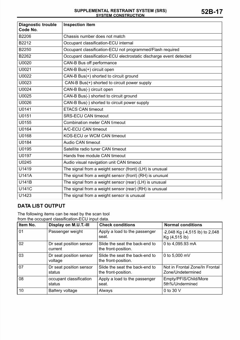
DATA LIST OUTPUT.
The following items can be read by the scan tool
from the occupant classification-ECU input data.
B2206 Chassis number does not match
B2212 Occupant classification-ECU internal
B2250 Occupant classification-ECU not programmed/Flash required
B2262 Occupant classification-ECU electrostatic discharge event detected
U0020 CAN-B Bus off performance
U0021 CAN-B Bus(+) circuit open
U0022 CAN-B Bus(+) shorted to circuit ground
U0023 CAN-B Bus(+) shorted to circuit power supply
U0024 CAN-B Bus(-) circuit open
U0025 CAN-B Bus(-) shorted to circuit ground
U0026 CAN-B Bus(-) shorted to circuit power supply
U0141 ETACS CAN timeout
U0151 SRS-ECU CAN timeout
U0155 Combination meter CAN timeout
U0164 A/C-ECU CAN timeout
U0168 KOS-ECU or WCM CAN timeout
U0184 Audio CAN timeout
U0195 Satellite radio tuner CAN timeout
U0197 Hands free module CAN timeout
U0245 Audio visual navigation unit CAN timeout
U1419 The signal from a weight sensor (front) (LH) is unusual
U141A The signal from a weight sensor (front) (RH) is unusual
U141B The signal from a weight sensor (rear) (LH) is unusual
U141C The signal from a weight sensor (rear) (RH) is unusual
U1423 The signal from a weight sensor is unusual
Diagnostic trouble
Code No.
Inspection item
Item No. Display on M.U.T.-III Check conditions Normal conditions
01 Passenger weight Apply a load to the passenger
seat.
−2,048 Kg (−4,515 Ib) to 2,048
Kg (4,515 Ib)02 Dr seat position sensor
current
Slide the seat the back-end to
the front-position.
0 to 4,095.93 mA
03 Dr seat position sensor
voltage
Slide the seat the back-end to
the front-position.
0 to 5,000 mV
07 Dr seat position sensor
status
Slide the seat the back-end to
the front-position.
Not in Frontal Zone/In Frontal
Zone/Undetermined
08 occupant classification
status
Apply a load to the passenger
seat.
Empty/PFIS/Child/More
5th%/Undermined
10 Battery voltage Always 0 to 30 V
8/19/2019 LancerX SRS
http://slidepdf.com/reader/full/lancerx-srs 18/26
SYSTEM CONSTRUCTION
SUPPLEMENTAL RESTRAINT SYSTEM (SRS)52B-18
ACCURACY CHECK OCCUPANT classification sensor The scan tool can be used to perform the next func-
tion.
• seat weight sensor Accuracy Check
• Zero-calibration
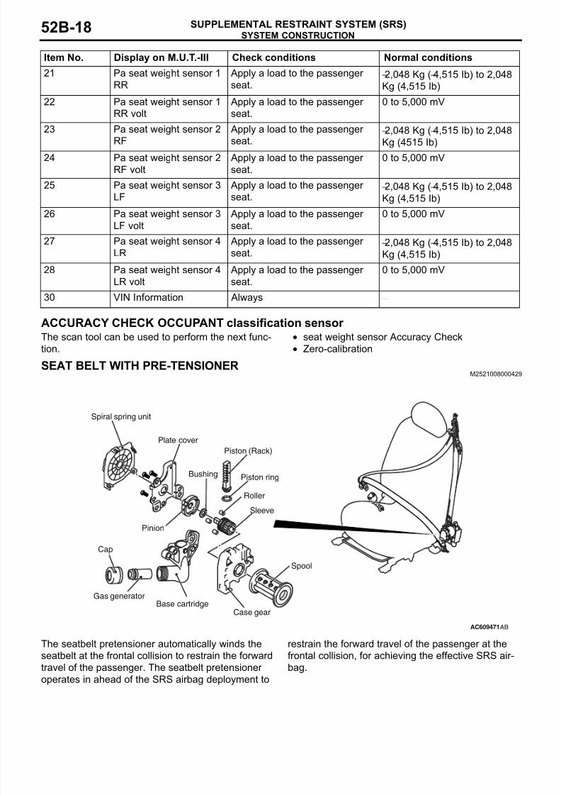
SEAT BELT WITH PRE-TENSIONERM2521008000429
The seatbelt pretensioner automatically winds the
seatbelt at the frontal collision to restrain the forward
travel of the passenger. The seatbelt pretensioner
operates in ahead of the SRS airbag deployment to
restrain the forward travel of the passenger at the
frontal collision, for achieving the effective SRS air-
bag.
21 Pa seat weight sensor 1
RR
Apply a load to the passenger
seat.−2,048 Kg (−4,515 Ib) to 2,048
Kg (4,515 Ib)
22 Pa seat weight sensor 1
RR volt
Apply a load to the passenger
seat.
0 to 5,000 mV
23 Pa seat weight sensor 2
RF
Apply a load to the passenger
seat.
−2,048 Kg (−4,515 Ib) to 2,048
Kg (4515 Ib)
24 Pa seat weight sensor 2
RF volt
Apply a load to the passenger
seat.
0 to 5,000 mV
25 Pa seat weight sensor 3
LF
Apply a load to the passenger
seat.−2,048 Kg (−4,515 Ib) to 2,048
Kg (4,515 Ib)
26 Pa seat weight sensor 3
LF volt
Apply a load to the passenger
seat.
0 to 5,000 mV
27 Pa seat weight sensor 4
LR
Apply a load to the passenger
seat.−2,048 Kg (−4,515 Ib) to 2,048
Kg (4,515 Ib)
28 Pa seat weight sensor 4
LR volt
Apply a load to the passenger
seat.
0 to 5,000 mV
30 VIN Information Always −
Item No. Display on M.U.T.-III Check conditions Normal conditions
AC609471
Piston (Rack)
Spool
Cap
Pinion
Sleeve
Roller
Gas generator
Case gearBase cartridge
Plate cover
Bushing Piston ring
Spiral spring unit
AB
8/19/2019 LancerX SRS
http://slidepdf.com/reader/full/lancerx-srs 19/26
SYSTEM CONSTRUCTION
SUPPLEMENTAL RESTRAINT SYSTEM (SRS) 52B-19
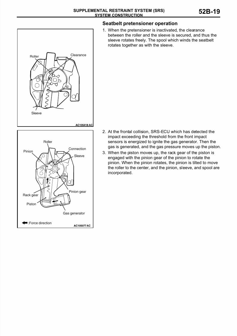
Seatbelt pretensioner operation
1. When the pretensioner is inactivated, the clearance
between the roller and the sleeve is secured, and thus the
sleeve rotates freely. The spool which winds the seatbelt
rotates together as with the sleeve.
2. At the frontal collision, SRS-ECU which has detected the
impact exceeding the threshold from the front impact
sensors is energized to ignite the gas generator. Then the
gas is generated, and the gas pressure moves up the piston.
3. When the piston moves up, the rack gear of the piston is
engaged with the pinion gear of the pinion to rotate the
pinion. When the pinion rotates, the pinion is tilted to move
the roller to the center, and the pinion, sleeve, and spool are
incorporated.
AC105418
Clearance
AC
Roller
Sleeve
AC105077:Force direction
Connection
AC
Gas generator
Piston
Sleeve
Pinion
Roller
Pinion gearRack gear
8/19/2019 LancerX SRS
http://slidepdf.com/reader/full/lancerx-srs 20/26
SYSTEM CONSTRUCTION
SUPPLEMENTAL RESTRAINT SYSTEM (SRS)52B-20
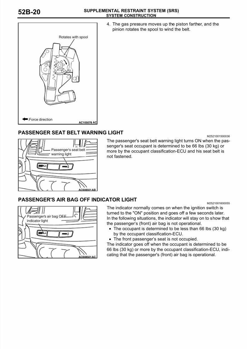
4. The gas pressure moves up the piston farther, and the
pinion rotates the spool to wind the belt.
PASSENGER SEAT BELT WARNING LIGHTM2521001500036
The passenger's seat belt warning light turns ON when the pas-
senger's seat occupant is determined to be 66 lbs (30 kg) or
more by the occupant classification-ECU and his seat belt is
not fastened.
PASSENGER'S AIR BAG OFF INDICATOR LIGHTM2521001600055
The indicator normally comes on when the ignition switch is
turned to the "ON" position and goes off a few seconds later.
In the following situations, the indicator will stay on to show that
the passenger’s (front) air bag is not operational.
• The occupant is determined to be less than 66 lbs (30 kg)
by the occupant classification-ECU.
• The front passenger’s seat is not occupied.
The indicator goes off when the occupant is determined to be66 lbs (30 kg) or more by the occupant classification-ECU, indi-
cating that the passenger's (front) air bag is operational.
AC105078 AC
Rotates with spool
:Force direction
AC608501
Passenger's seat belt
warning light
AB
AC608501
Passenger's air bag OFF
indicator light
AC
8/19/2019 LancerX SRS
http://slidepdf.com/reader/full/lancerx-srs 21/26
SYSTEM CONSTRUCTION
SUPPLEMENTAL RESTRAINT SYSTEM (SRS) 52B-21
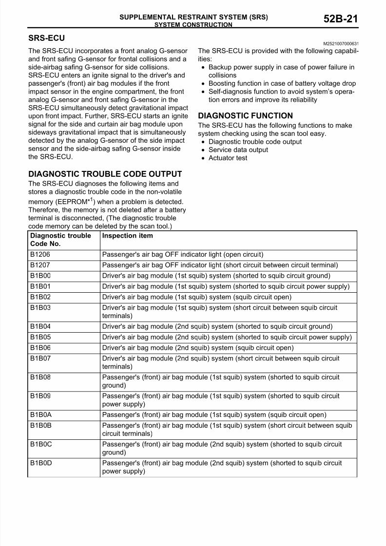
SRS-ECUM2521007000631
The SRS-ECU incorporates a front analog G-sensor
and front safing G-sensor for frontal collisions and a
side-airbag safing G-sensor for side collisions.
SRS-ECU enters an ignite signal to the driver's and
passenger's (front) air bag modules if the front
impact sensor in the engine compartment, the front
analog G-sensor and front safing G-sensor in the
SRS-ECU simultaneously detect gravitational impact
upon front impact. Further, SRS-ECU starts an ignite
signal for the side and curtain air bag module upon
sideways gravitational impact that is simultaneously
detected by the analog G-sensor of the side impact
sensor and the side-airbag safing G-sensor inside
the SRS-ECU.
The SRS-ECU is provided with the following capabil-
ities:
• Backup power supply in case of power failure in
collisions
• Boosting function in case of battery voltage drop
• Self-diagnosis function to avoid system’s opera-
tion errors and improve its reliability
DIAGNOSTIC FUNCTIONThe SRS-ECU has the following functions to make
system checking using the scan tool easy.
• Diagnostic trouble code output
• Service data output
• Actuator test
DIAGNOSTIC TROUBLE CODE OUTPUTThe SRS-ECU diagnoses the following items and
stores a diagnostic trouble code in the non-volatilememory (EEPROM*1) when a problem is detected.
Therefore, the memory is not deleted after a battery
terminal is disconnected, (The diagnostic trouble
code memory can be deleted by the scan tool.)
Diagnostic trouble
Code No.
Inspection item
B1206 Passenger's air bag OFF indicator light (open circuit)
B1207 Passenger's air bag OFF indicator light (short circuit between circuit terminal)
B1B00 Driver's air bag module (1st squib) system (shorted to squib circuit ground)
B1B01 Driver's air bag module (1st squib) system (shorted to squib circuit power supply)B1B02 Driver's air bag module (1st squib) system (squib circuit open)
B1B03 Driver's air bag module (1st squib) system (short circuit between squib circuit
terminals)
B1B04 Driver's air bag module (2nd squib) system (shorted to squib circuit ground)
B1B05 Driver's air bag module (2nd squib) system (shorted to squib circuit power supply)
B1B06 Driver's air bag module (2nd squib) system (squib circuit open)
B1B07 Driver's air bag module (2nd squib) system (short circuit between squib circuit
terminals)
B1B08 Passenger's (front) air bag module (1st squib) system (shorted to squib circuit
ground)
B1B09 Passenger's (front) air bag module (1st squib) system (shorted to squib circuit
power supply)
B1B0A Passenger's (front) air bag module (1st squib) system (squib circuit open)
B1B0B Passenger's (front) air bag module (1st squib) system (short circuit between squib
circuit terminals)
B1B0C Passenger's (front) air bag module (2nd squib) system (shorted to squib circuit
ground)
B1B0D Passenger's (front) air bag module (2nd squib) system (shorted to squib circuit
power supply)
8/19/2019 LancerX SRS
http://slidepdf.com/reader/full/lancerx-srs 22/26
SYSTEM CONSTRUCTION
SUPPLEMENTAL RESTRAINT SYSTEM (SRS)52B-22
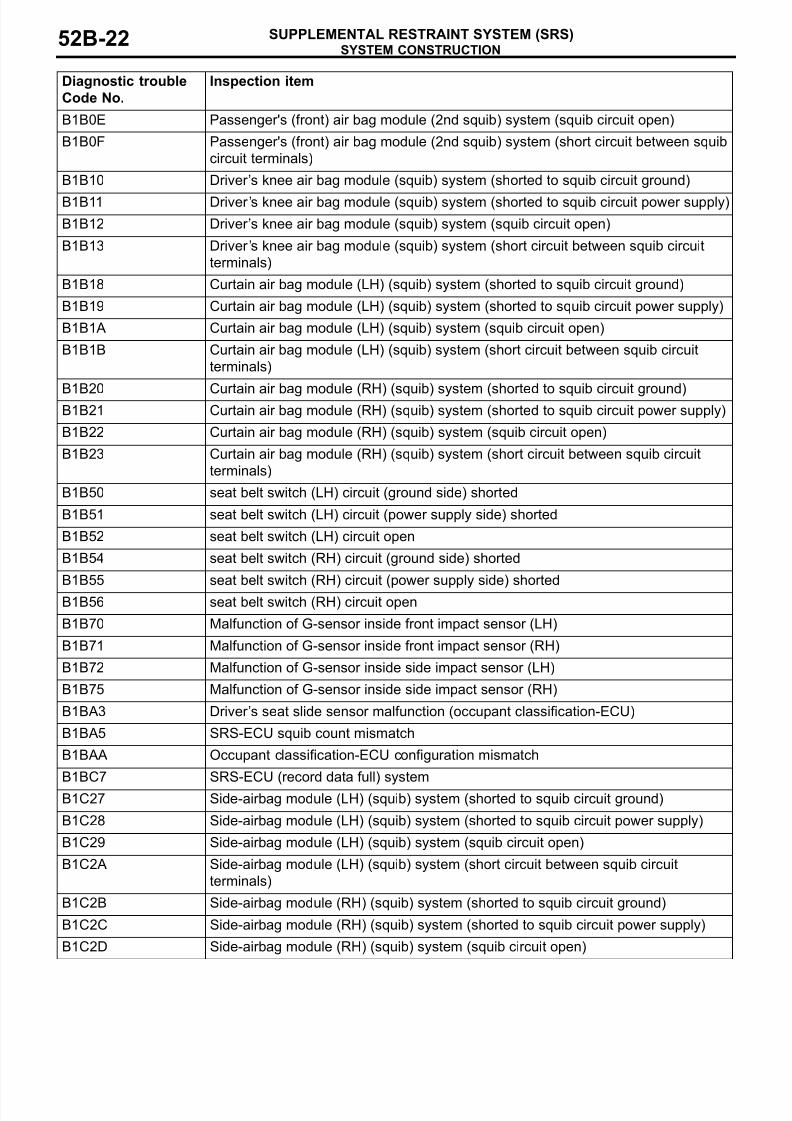
B1B0E Passenger's (front) air bag module (2nd squib) system (squib circuit open)
B1B0F Passenger's (front) air bag module (2nd squib) system (short circuit between squib
circuit terminals)
B1B10 Driver’s knee air bag module (squib) system (shorted to squib circuit ground)
B1B11 Driver ’s knee air bag module (squib) system (shorted to squib circuit power supply)
B1B12 Driver’s knee air bag module (squib) system (squib circuit open)
B1B13 Driver ’s knee air bag module (squib) system (short circuit between squib circuit
terminals)
B1B18 Curtain air bag module (LH) (squib) system (shorted to squib circuit ground)
B1B19 Curtain air bag module (LH) (squib) system (shorted to squib circuit power supply)
B1B1A Curtain air bag module (LH) (squib) system (squib circuit open)
B1B1B Curtain air bag module (LH) (squib) system (short circuit between squib circuit
terminals)
B1B20 Curtain air bag module (RH) (squib) system (shorted to squib circuit ground)B1B21 Curtain air bag module (RH) (squib) system (shorted to squib circuit power supply)
B1B22 Curtain air bag module (RH) (squib) system (squib circuit open)
B1B23 Curtain air bag module (RH) (squib) system (short circuit between squib circuit
terminals)
B1B50 seat belt switch (LH) circuit (ground side) shorted
B1B51 seat belt switch (LH) circuit (power supply side) shorted
B1B52 seat belt switch (LH) circuit open
B1B54 seat belt switch (RH) circuit (ground side) shorted
B1B55 seat belt switch (RH) circuit (power supply side) shorted
B1B56 seat belt switch (RH) circuit open
B1B70 Malfunction of G-sensor inside front impact sensor (LH)
B1B71 Malfunction of G-sensor inside front impact sensor (RH)
B1B72 Malfunction of G-sensor inside side impact sensor (LH)
B1B75 Malfunction of G-sensor inside side impact sensor (RH)
B1BA3 Driver’s seat slide sensor malfunction (occupant classification-ECU)
B1BA5 SRS-ECU squib count mismatch
B1BAA Occupant classification-ECU configuration mismatch
B1BC7 SRS-ECU (record data full) system
B1C27 Side-airbag module (LH) (squib) system (shorted to squib circuit ground)
B1C28 Side-airbag module (LH) (squib) system (shorted to squib circuit power supply)
B1C29 Side-airbag module (LH) (squib) system (squib circuit open)
B1C2A Side-airbag module (LH) (squib) system (short circuit between squib circuit
terminals)
B1C2B Side-airbag module (RH) (squib) system (shorted to squib circuit ground)
B1C2C Side-airbag module (RH) (squib) system (shorted to squib circuit power supply)
B1C2D Side-airbag module (RH) (squib) system (squib circuit open)
Diagnostic trouble
Code No.
Inspection item
8/19/2019 LancerX SRS
http://slidepdf.com/reader/full/lancerx-srs 23/26
SYSTEM CONSTRUCTION
SUPPLEMENTAL RESTRAINT SYSTEM (SRS) 52B-23
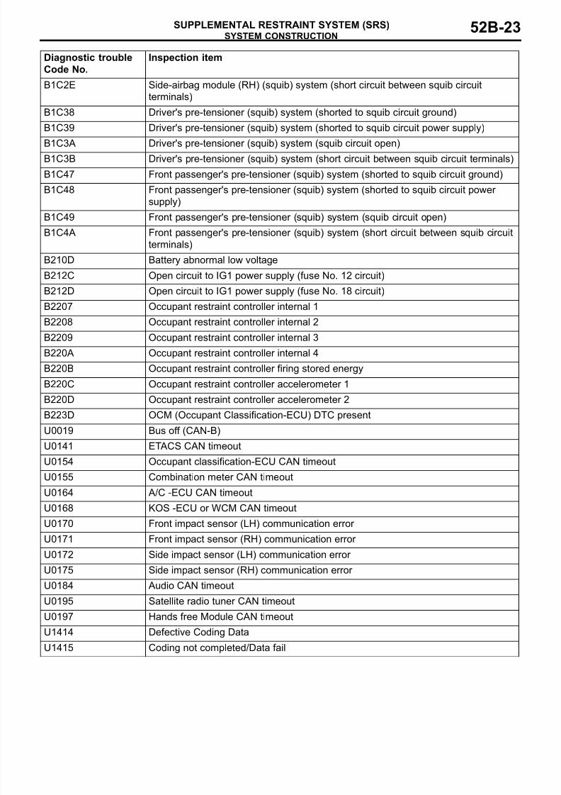
B1C2E Side-airbag module (RH) (squib) system (short circuit between squib circuit
terminals)
B1C38 Driver's pre-tensioner (squib) system (shorted to squib circuit ground)
B1C39 Driver's pre-tensioner (squib) system (shorted to squib circuit power supply)
B1C3A Driver's pre-tensioner (squib) system (squib circuit open)
B1C3B Driver's pre-tensioner (squib) system (short circuit between squib circuit terminals)
B1C47 Front passenger's pre-tensioner (squib) system (shorted to squib circuit ground)
B1C48 Front passenger's pre-tensioner (squib) system (shorted to squib circuit power
supply)
B1C49 Front passenger's pre-tensioner (squib) system (squib circuit open)
B1C4A Front passenger's pre-tensioner (squib) system (short circuit between squib circuit
terminals)
B210D Battery abnormal low voltage
B212C Open circuit to IG1 power supply (fuse No. 12 circuit)B212D Open circuit to IG1 power supply (fuse No. 18 circuit)
B2207 Occupant restraint controller internal 1
B2208 Occupant restraint controller internal 2
B2209 Occupant restraint controller internal 3
B220A Occupant restraint controller internal 4
B220B Occupant restraint controller firing stored energy
B220C Occupant restraint controller accelerometer 1
B220D Occupant restraint controller accelerometer 2
B223D OCM (Occupant Classification-ECU) DTC presentU0019 Bus off (CAN-B)
U0141 ETACS CAN timeout
U0154 Occupant classification-ECU CAN timeout
U0155 Combination meter CAN timeout
U0164 A/C -ECU CAN timeout
U0168 KOS -ECU or WCM CAN timeout
U0170 Front impact sensor (LH) communication error
U0171 Front impact sensor (RH) communication error
U0172 Side impact sensor (LH) communication error U0175 Side impact sensor (RH) communication error
U0184 Audio CAN timeout
U0195 Satellite radio tuner CAN timeout
U0197 Hands free Module CAN timeout
U1414 Defective Coding Data
U1415 Coding not completed/Data fail
Diagnostic trouble
Code No.
Inspection item
8/19/2019 LancerX SRS
http://slidepdf.com/reader/full/lancerx-srs 24/26
SYSTEM CONSTRUCTION
SUPPLEMENTAL RESTRAINT SYSTEM (SRS)52B-24
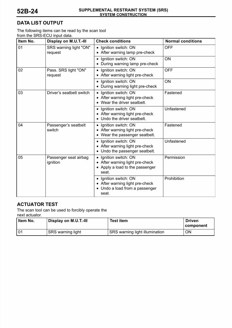
DATA LIST OUTPUT.
The following items can be read by the scan tool
from the SRS-ECU input data.
ACTUATOR TESTThe scan tool can be used to forcibly operate the
next actuator.
Item No. Display on M.U.T.-III Check conditions Normal conditions
01 SRS warning light "ON"
request
• Ignition switch: ON
• After warning lamp pre-check
OFF
• Ignition switch: ON• During warning lamp pre-check
ON
02 Pass. SRS light "ON"
request
• Ignition switch: ON
• After warning light pre-check
OFF
• Ignition switch: ON
• During warning light pre-check
ON
03 Driver’s seatbelt switch • Ignition switch: ON
• After warning light pre-check
• Wear the driver seatbelt.
Fastened
• Ignition switch: ON
• After warning light pre-check
• Undo the driver seatbelt.
Unfastened
04 Passenger’s seatbelt
switch
• Ignition switch: ON
• After warning light pre-check
• Wear the passenger seatbelt.
Fastened
• Ignition switch: ON
• After warning light pre-check
• Undo the passenger seatbelt.
Unfastened
05 Passenger seat airbag
ignition
• Ignition switch: ON
• After warning light pre-check
• Apply a load to the passenger
seat.
Permission
• Ignition switch: ON
• After warning light pre-check
• Undo a load from a passenger
seat.
Prohibition
Item No. Display on M.U.T.-III Test item Driven
component
01 SRS warning light SRS warning light illumination ON
8/19/2019 LancerX SRS
http://slidepdf.com/reader/full/lancerx-srs 25/26
SYSTEM CONSTRUCTION
SUPPLEMENTAL RESTRAINT SYSTEM (SRS) 52B-25
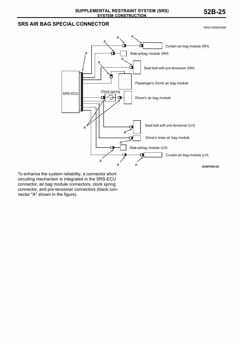
SRS AIR BAG SPECIAL CONNECTORM2521009000466
.
To enhance the system reliability, a connector short
circuiting mechanism is integrated in the SRS-ECUconnector, air bag module connectors, clock spring
connector, and pre-tensioner connectors (black con-
nector "A" shown in the figure).
.
AC607646AD
SRS-ECU
A
A
A
A
A
A
AA
A
A
Clock spring
Side-airbag module (RH)
Seat belt with pre-tensioner (LH)
Side-airbag module (LH)
Seat belt with pre-tensioner (RH)
Passenger's (front) air bag module
Driver's air bag module
Curtain air bag module (RH)
Curtain air bag module (LH)
Driver's knee air bag module
A
A
8/19/2019 LancerX SRS
http://slidepdf.com/reader/full/lancerx-srs 26/26
SYSTEM CONSTRUCTION
SUPPLEMENTAL RESTRAINT SYSTEM (SRS)52B-26
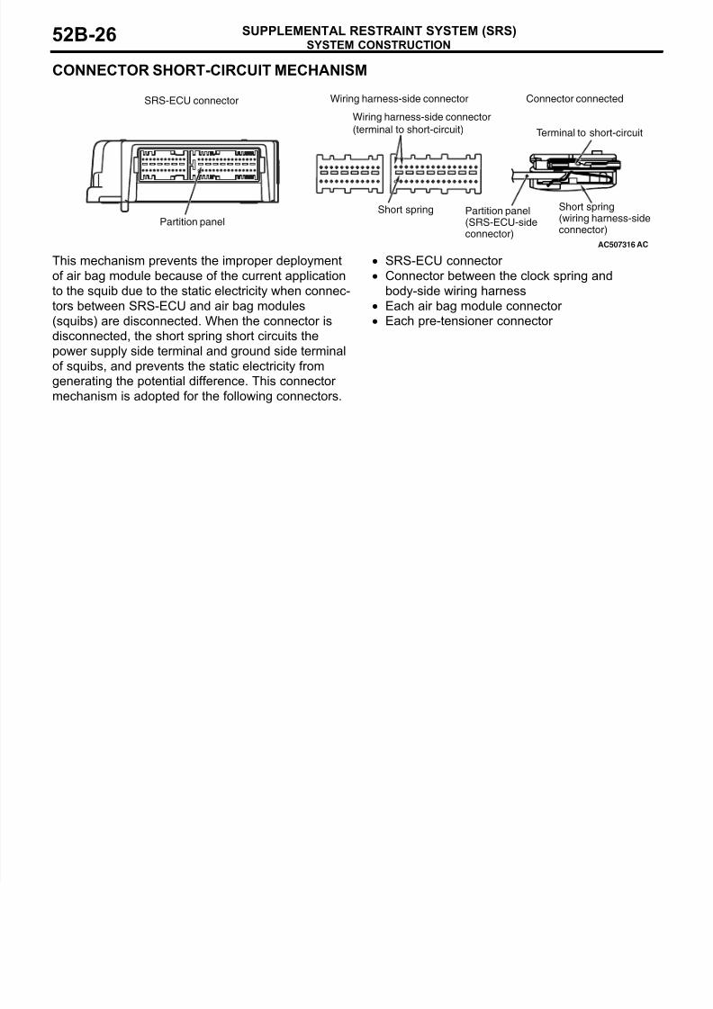
CONNECTOR SHORT-CIRCUIT MECHANISM
This mechanism prevents the improper deployment
of air bag module because of the current application
to the squib due to the static electricity when connec-
tors between SRS-ECU and air bag modules
(squibs) are disconnected. When the connector is
disconnected, the short spring short circuits the
power supply side terminal and ground side terminalof squibs, and prevents the static electricity from
generating the potential difference. This connector
mechanism is adopted for the following connectors.
• SRS-ECU connector
• Connector between the clock spring and
body-side wiring harness
• Each air bag module connector
• Each pre-tensioner connector
AC507316
SRS-ECU connector
AC
Partition panel(SRS-ECU-sideconnector)
Partition panel
Wiring harness-side connector
(terminal to short-circuit)
Short spring Short spring(wiring harness-sideconnector)
Connector connectedWiring harness-side connector
Terminal to short-circuit