Instruction N&D.35 Xtreme 002 035746 - BFT Gate Openers · La barriera automatica elettromeccanica...
32
,6758=,21, '¶862 ( ', ,167$//$=,21( ,167$//$7,21 $1' 86(5¶6 0$18$/ ,16758&7,216 '¶87,/,6$7,21 (7 '¶,167$//$7,21 ,167$//$7,21681' *(%5$8&+6$1/(,781* ,16758&&,21(6 '( 862 < '( ,167$/$&,21 0$;,0$ 8/75$ 0$;,0$ 8/75$ Attenzione! Leggere attentamente le “Avvertenze” all’interno! Caution! Read “Warnings” inside carefully! Attention! Veuillez lire attentivement les Avertissements qui se trouvent à l’intérieur! Achtung! Bitte lesen Sie aufmerksam die „Hinweise“ im Inneren! ¡Atención¡ Leer atentamente las “Advertencias” en el interior! Let op! Lees de “Waarschuwingen” aan de binnenkant zorgvuldig! %$55,(5$ $8720$7,&$ $8720$7,& %$55,(5 %$55,Ê5( $8720$7,48( $8720$7,6&+( 6&+5$1.( %$55(5$ $8720È7,&$ D812170 00550_02 04-09-15 www.BFTGateOpeners.com (800) 878-7829
Transcript of Instruction N&D.35 Xtreme 002 035746 - BFT Gate Openers · La barriera automatica elettromeccanica...

Attenzione! Leggere attentamente le “Avvertenze” all’interno! Caution! Read “Warnings” inside carefully! Attention! Veuillez lire attentivement les Avertissements qui se trouvent à l’intérieur! Achtung! Bitte lesen Sie aufmerksam die „Hinweise“ im Inneren! ¡Atención¡ Leer atentamente las “Advertencias” en el interior! Let op! Lees de “Waarschuwingen” aan de binnenkant zorgvuldig!
D81
2170
005
50_0
2 04
-09-
15
www.BFTGateOpeners.com(800) 878-7829

ITA
LIA
NO
EN
GL
ISH
FR
AN
ÇA
ISD
EU
TS
CH
ES
PA
ÑO
L
1. Informazioni generali
1.1 Introduzione ..................................................................pag. 4 1.2 Sicurezza generale ......................................................pag. 4 1.3 Generalità .......................................................................pag. 4 1.4 Dati tecnici .....................................................................pag. 4 1.5 Dimensioni d’ingombro ............................................pag. 4
2. Installazione
2.1 Nota cavi .........................................................................pag. 5 2.2 Fissaggio struttura ......................................................pag. 5 2.3 Installazione barra .......................................................pag. 6
2.4 Allineamento barra .....................................................pag. 6 2.5 Equilibratura della barra ...........................................pag. 7 2.6 Optionals ........................................................................pag. 7 2.7 Collegamenti elettrici ................................................pag. 7
3. Uso e manutenzione
3.1 Sicurezza generale ......................................................pag. 8 3.2 Avvertenze .....................................................................pag. 8 3.3 Uso ....................................................................................pag. 8 3.4 Manutenzione ordinaria ...........................................pag. 8 3.5 Manovra manuale .......................................................pag. 8
Indice
Index
Index
Verzeichnis
Índice
1. General information
1.1 Introduction ...................................................................pag. 9 1.2 General safety ...............................................................pag. 9 1.3 General ............................................................................pag. 9 1.4 Technical specifi cation ..............................................pag. 9 1.5 Overall dimensions .....................................................pag. 9
2. Installation
2.1 Cable note ......................................................................pag. 10 2.2 Fixing the structure ....................................................pag. 10 2.3 Instal the arm ...............................................................pag. 11
2.4 Align the arm ................................................................pag. 11 2.5 Balancing the arm .......................................................pag. 12 2.6 Optionals ........................................................................pag. 12 2.7 Electrical connections ................................................pag. 12
3. Use and maintenance
3.1 General safety ...............................................................pag. 13 3.2 Warnings .........................................................................pag. 13 3.3 Use ....................................................................................pag. 13 3.4 Routine maintenance ................................................pag. 13 3.5 Manual manoeuvre ....................................................pag. 13
1. Information generales
1.1 Avant-propos.................................................................pag. 14 1.2 Securite generale ........................................................pag. 14 1.3 Generalities ....................................................................pag. 14 1.4 Données techniques ..................................................pag. 14 1.5 Dimensions hors-tout ................................................pag. 14
2. Installations
2.1 Connexion cables ........................................................pag. 15 2.2 Fixation structure ........................................................pag. 15 2.3 Installation de la lisse ................................................pag. 16
2.4 Alignement de la lisse ...............................................pag. 16 2.5 Equilibrage de la lisse ...............................................pag. 17 2.6 Optionals ........................................................................pag. 17 2.7 Branchements electriques .......................................pag. 17
3. Utilisation et maintenance
3.1 Sécurité générale ........................................................pag. 18 3.2 Avertissements .............................................................pag. 18 3.3 Utilisation .......................................................................pag. 18 3.4 Routine maintenance ................................................pag. 18 3.5 Manoeuvre manuelle .................................................pag. 18
1. Allgemeine informationen
1.1 Einleitung .......................................................................pag. 19 1.2 Allgemeine sicherheitshinweise ............................pag. 19 1.3 Allgemeines ...................................................................pag. 19 1.4 Technische daten ........................................................pag. 19 1.5 Abmessungen ...............................................................pag. 19
2. Installation
2.1 Bemerkung zu den kabel anschlüssen ...............pag. 20 2.2 Strukturbefestigung ...................................................pag. 20 2.3 Installation des baums ..............................................pag. 21
2.4 Die schranke ausrichten ...........................................pag. 21 2.5 Ausbilancierung des baumes .................................pag. 22 2.6 Optionals ........................................................................pag. 22 2.7 Elektrische anschlüsse ..............................................pag. 22
3. Gebrauchs und Wartungsanleitungen
3.1 Allgemeine sicherheit ................................................pag. 23 3.2 Hinweise..........................................................................pag. 23 3.3 Betrieb .............................................................................pag. 23 3.4 Ordentliche wartung ..................................................pag. 23 3.5 Manuelles manövrieren ............................................pag. 23
1. Informaciones generales
1.1 Introducción ..................................................................pag. 24 1.2 Seguridad general .......................................................pag. 24 1.3 Generalidad ...................................................................pag. 24 1.4 Datos técnicos ..............................................................pag. 24 1.5 Medidas ...........................................................................pag. 24
2. Instalación
2.1 Nota cables ....................................................................pag. 25 2.2 Fijación estructura ......................................................pag. 25 2.3 Instalación de la barra...............................................pag. 26
2.4 Alinear la barra .............................................................pag. 26 2.5 Equilibrado de la barra .............................................pag. 27 2.6 Optionals ........................................................................pag. 27 2.7 Conexiones eléctricas ................................................pag. 27
3. Uso y mantenimiento
3.1 Seguridad general .......................................................pag. 28 3.2 Advertencias ..................................................................pag. 28 3.3 Uso ....................................................................................pag. 28 3.4 Mantenimiento ordinario .........................................pag. 28 3.5 Maniobra manual ........................................................pag. 28
- 4 -
ITA
LIA
NO
460
950
1110
320 28040100
1.5 DIMENSIONI D’INGOMBRO
Barriera DESTRA
Barriera SINISTRA
1.1 INTRODUZIONE
Leggere attentamente il libretto prima di installare il prodotto, utilizzarlo e prima di eseguire manutenzione ordinaria o straordinaria.
Le indicazioni precedute da questo simbolo contengono informazioni di particolare importanza, il loro mancato rispetto può
comportare la perdita della garanzia contrattuale.
LE OPERAZIONI CHE EFFETTUATE IN MODO NON CORRETTO POSSONO PRESENTARE RISCHI SONO INDICATE CON I SIMBOLI:
FOLGORAZIONE SCHIACCIAMENTO
Il libretto di INSTALLAZIONE USO E MANUTENZIONE è destinato agli installatori, agli utilizzatori ed agli operatori della manutenzione.
La Ditta non è responsabile per danni arrecati a persone, animali o cose dovuti ad applicazioni che superano i limiti indicati nella scheda tecnica
allegata o dall’uso diverso da quello per cui il prodotto è stato progettato.
1.2 SICUREZZA GENERALE
• Smaltire i materiali di imballo (plastica, cartone, polistirolo, ecc.) secondo quanto previsto dalle norme vigenti. Non lasciare buste di nylon e polistirolo a portata dei bambini.• Non installare il prodotto in atmosfera esplosiva.• Togliere l’alimentazione elettrica, prima di qualsiasi intervento sull’impianto. Scollegare anche eventuali batterie tampone se presenti.• Prevedere sulla rete di alimentazione dell’automazione, un interruttore o un magnetotermico onnipolare con distanza di apertura dei contatti uguale o superiore a 3,5 mm.• Verifi care che a monte della rete di alimentazione, vi sia un interruttore diff erenziale con soglia da 0,03A.• Applicare tutti i dispositivi di sicurezza (fotocellule, coste sensibili, ecc.) necessari a proteggere l’area da pericoli di schiacciamento, convogliamento, cesoiamento, secondo ed in conformità alle direttive e norme tecniche applicabili.• La Ditta declina ogni responsabilità ai fi ni della sicurezza e del buon funzionamento dell’automazione se vengono impiegati componenti di altri produttori.• Usare esclusivamente parti originali per qualsiasi manutenzione o riparazione.• Non eseguire alcuna modifi ca ai componenti dell’automazione se non espressamente autorizzata dalla Ditta.• Istruire l’utilizzatore dell’impianto per quanto riguarda i sistemi di comando applicati e l’esecuzione dell’apertura manuale in caso di emergenza.• Non permettere a persone e bambini di sostare nell’area d’azione dell’automazione.• Non lasciare radiocomandi o altri dispositivi di comando alla portata dei bambini onde evitare azionamenti involontari dell’automazione.• Tutto quello che non è espressamente previsto in queste istruzioni, non è permesso.
1.3 GENERALITA’
La barriera automatica elettromeccanica è stata progettata per gestire passaggi con luce fi no a 5 metri nel rispetto delle normative europee. E’ la soluzione ideale per la gestione veicolare.
1.4 DATI TECNICI
Lunghezza barra .............................................................................................................. 1,7 ÷ 5mTemp. di esercizio ......................................................................................................... -30 +60°CManovre in 24h ....................................................................................20 000 barra fi no a 3m 5 000 barra fi no a 5mGrado di protezione ............................................................................................................... IP 54
Peso............................................................................................................................................~70 kg
Alimentazione ........................................................... 230Vac/115Vac ±10% 50/60 HzMotore ........................................................................................ 230Vac 910RPM 0,25kWPotenza assorbita...........................................................................................................370WCentralina ............................................................................................................ CSB-Xtreme
Sicurezza all’urto ....................................................................................................... EncoderTempo di apertura ....................................................................................................... 0,7 ÷ 3,0 s
IT 1. Informazioni generali
- 5 -
ITA
LIA
NO
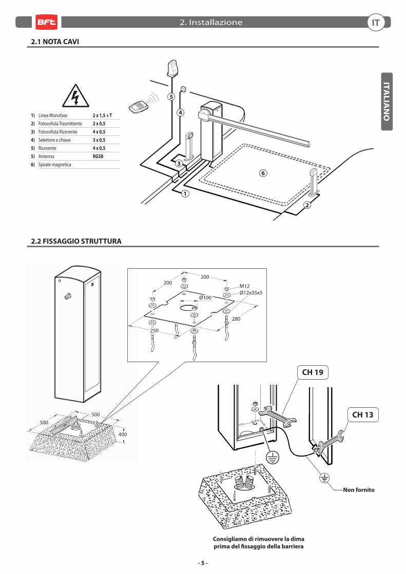
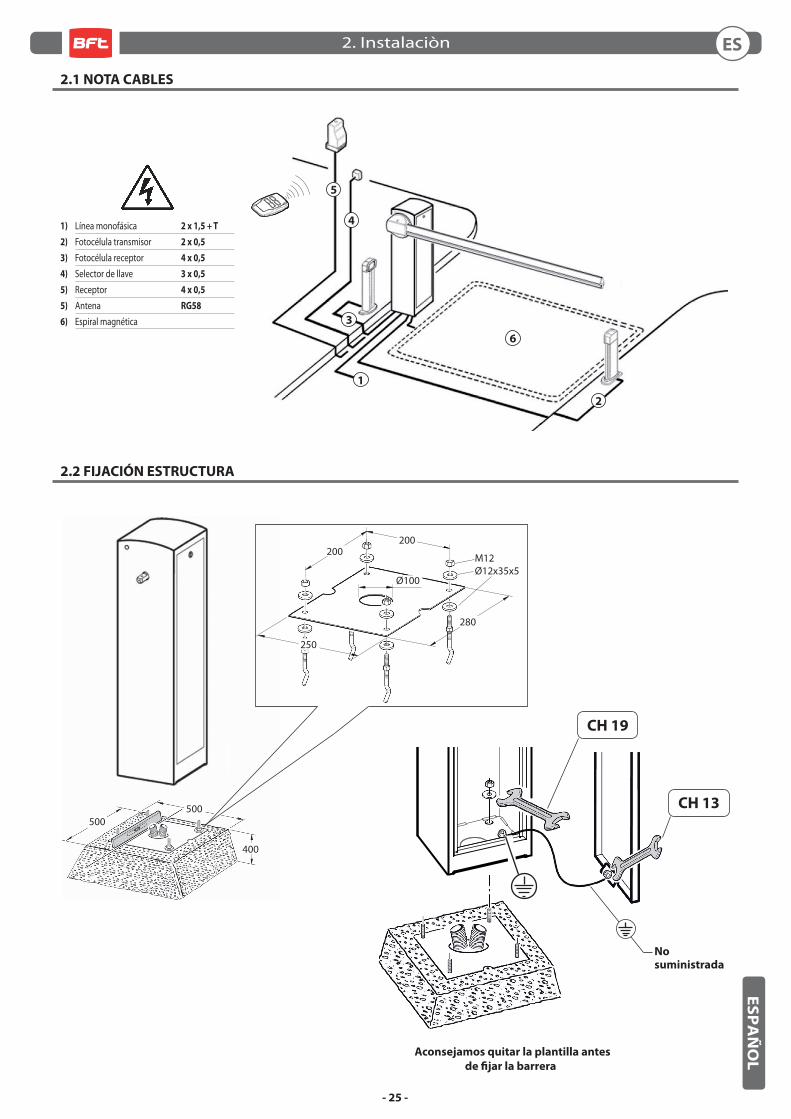
2.1 NOTA CAVI
2.2 FISSAGGIO STRUTTURA
5
6
3
1
2
4
500500
400
Consigliamo di rimuovere la dima
prima del fi ssaggio della barriera
CH 19
CH 13
Non fornito
1) Linea Monofase 2 x 1,5 + T
2) Fotocellula Trasmittente 2 x 0,5
3) Fotocellula Ricevente 4 x 0,5
4) Selettore a chiave 3 x 0,5
5) Ricevente 4 x 0,5
5) Antenna RG58
6) Spirale magnetica
M12Ø12x35x5
200200
250
280
Ø100
IT2. Installazione
- 6 -
ITA
LIA
NO
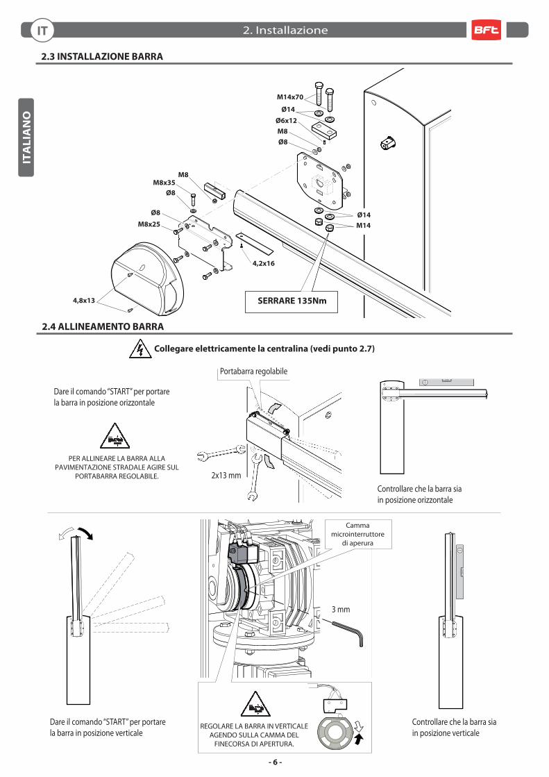
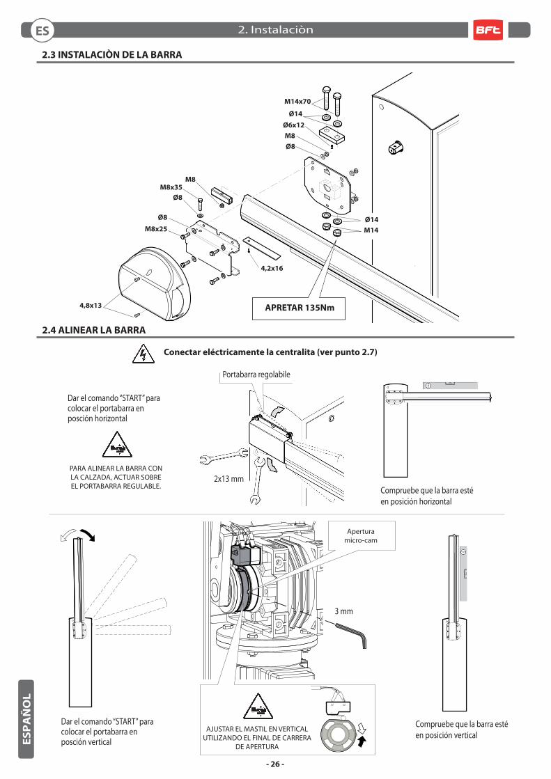
2.3 INSTALLAZIONE BARRA
2.4 ALLINEAMENTO BARRA
Portabarra regolabile
Collegare elettricamente la centralina (vedi punto 2.7)
PER ALLINEARE LA BARRA ALLA PAVIMENTAZIONE STRADALE AGIRE SUL
PORTABARRA REGOLABILE.
Ø8
M8x25
M8x35
Ø8
M8
Ø6x12
M14x70
Ø8
M8
4,8x13
2x13 mm
3 mm
Camma microinterruttore
di aperura
Ø14
M14
Ø14
Dare il comando “START” per portarela barra in posizione verticale
Dare il comando “START” per portarela barra in posizione orizzontale
Controllare che la barra siain posizione orizzontale
Controllare che la barra siain posizione verticale
SERRARE 135Nm
REGOLARE LA BARRA IN VERTICALEAGENDO SULLA CAMMA DEL
FINECORSA DI APERTURA.
4,2x16
IT 2. Installazione
- 7 -
ITA
LIA
NO
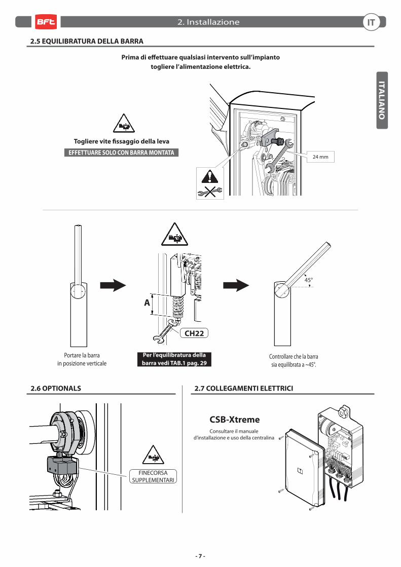
FINECORSASUPPLEMENTARI
Consultare il manuale d’installazione e uso della centralina
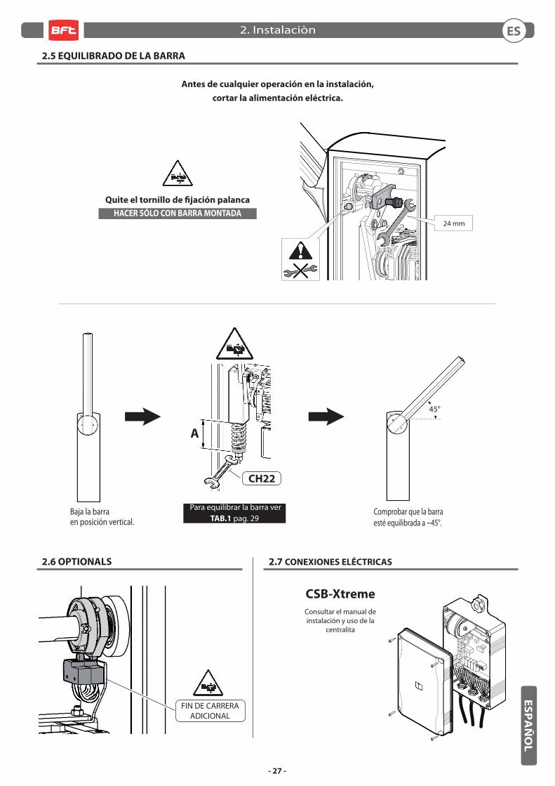
2.6 OPTIONALS 2.7 COLLEGAMENTI ELETTRICI
Per l’equilibratura della
barra vedi TAB.1 pag. 29
2.5 EQUILIBRATURA DELLA BARRA
CSB-Xtreme
EFFETTUARE SOLO CON BARRA MONTATA
Togliere vite fi ssaggio della leva
A
45°
CH22
Controllare che la barrasia equilibrata a ~45°.
Portare la barra in posizione verticale
Prima di eff ettuare qualsiasi intervento sull’impianto
togliere l’alimentazione elettrica.
24 mm
IT2. Installazione
- 8 -
ITA
LIA
NO
3.1 SICUREZZA GENERALE
• La barriera e’ ad uso esclusivamente veicolare, segnalare e delimitare tramite apposito cartello eventuali passaggi pedonali. • Tenere bambini, persone e cose fuori dal raggio d’azione dell’automazione, in particolare durante il funzionamento.• Si consiglia, per ragioni di sicurezza e nel rispetto delle normative vigenti, di utilizzare l’apposita centralina di comando.• L’installazione deve essere eseguita seguendo le prescrizioni contenute nel foglio allegato “AVVERTENZE GENERALI PER LA SICUREZZA”.• I collegamenti elettrici devono essere eff ettuati nel rispetto delle disposizioni legislative vigenti.• L’installatore deve istruire l’utilizzatore sul corretto funzionamento dell’automatismo, sulla manovra manuale d’emergenza e sui possibili rischi durante il funzionamento.• Eseguire l’analisi dei rischi prendendo opportuni provvedimenti per eliminarli, come prescritto dalla direttiva macchine 2006/42/CEE, installando i dispositivi di sicurezza.• Prima di eff ettuare qualsiasi intervento sull’impianto togliere l’alimentazione elettrica mediante un sezionatore.
3.2 AVVERTENZE
Il buon funzionamento dell’automazione è garantito solo se vengono rispettate i dati riportati in questo manuale. La Ditta non risponde dei danni
causati dall’inosservanza delle norme di installazione e delle indicazioni riportate in questo manuale.
Le descrizioni e le illustrazioni del presente manuale non sono impegnative. Lasciando inalterate le caratteristiche essenziali del prodotto, la
Ditta si riserva di apportare in qualunque momento le modifi che che essa ritiene convenienti per migliorare tecnicamente, costruttivamente e
commercialmente il prodotto, senza impegnarsi ad aggiornare la presente pubblicazione.
3.3 USO
• Seguire tassativamente le indicazioni contenute nel foglio allegato “AVVERTENZE GENERALI PER LA SICUREZZA”.• In caso di manovra manuale d’emergenza seguire le indicazioni descritte al punto 3.5.
• Consultare il manuale d’installazione e uso della centralina.
3.4 MANUTENZIONE ORDINARIA (OGNI SEI MESI)
• La manutenzione deve essere eseguita solo da personale qualifi cato.• Controllare lo stato della struttura della barriera.• Controllare lo stato del serraggio barra.• Controllare lo stato della molla, della catena e dei relativi ancoraggi. • Controllare l’equilibratura della barra.• Controllare che a fi necorsa la barra sia orizzontale e/o verticale• Verifi care il funzionamento della centralina e dei dispositivi di sicurezza• Verifi care il funzionamento della manovra manuale d’emergenza.• Registrare gli interventi di manutenzione nel modulo a pag. 30.
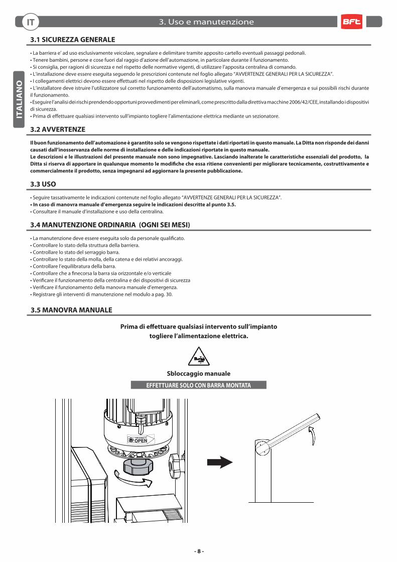
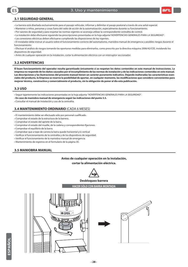
3.5 MANOVRA MANUALE
Sbloccaggio manuale
EFFETTUARE SOLO CON BARRA MONTATA
Prima di eff ettuare qualsiasi intervento sull’impianto
togliere l’alimentazione elettrica.
IT 3. Uso e manutenzione
- 9 -
EN
GL
ISH
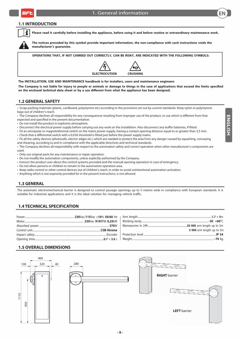
1.5 OVERALL DIMENSIONS
RIGHT barrier
LEFT barrier
1.1 INTRODUCTION
Please read it carefully before installing the appliance, before using it and before routine or extraordinary maintenance work.
The notices preceded by this symbol provide important information, the non-compliance with such instructions voids the
manufacturer’s guarantee.
OPERATIONS THAT, IF NOT CARRIED OUT CORRECTLY, CAN BE RISKY, ARE INDICATED WITH THE FOLLOWING SYMBOLS:
ELECTROCUTION CRUSHING
The INSTALLATION, USE AND MAINTENANCE handbook is for installers, users and maintenance engineers
The Company is not liable for injury to people or animals or damage to things in the case of applications that exceed the limits specifi ed
on the enclosed technical data sheet or by a use diff erent from what the appliance has been designed.
1.2 GENERAL SAFETY
• Scrap packing materials (plastic, cardboard, polystyrene etc) according to the provisions set out by current standards. Keep nylon or polystyrene bags out of children’s reach.• The Company declines all responsibility for any consequences resulting from improper use of the product, or use which is diff erent from that expected and specifi ed in the present documentation.• Do not install the product in explosive atmosphere.• Disconnect the electrical power supply before carrying out any work on the installation. Also disconnect any buff er batteries, if fi tted.• Fit an omnipolar or magnetothermal switch on the mains power supply, having a contact opening distance equal to or greater than 3,5 mm.• Check that a diff erential switch with a 0,03A threshold is fi tted just before the power supply mains.• Fit all the safety devices (photocells, electric edges etc.) which are needed to protect the area from any danger caused by squashing, conveying and shearing, according to and in compliance with the applicable directives and technical standards.• The Company declines all responsibility with respect to the automation safety and correct operation when other manufacturer’s components are used.• Only use original parts for any maintenance or repair operation.• Do not modify the automation components, unless explicitly authorised by the Company.• Instruct the product user about the control systems provided and the manual opening operation in case of emergency.• Do not allow persons or children to remain in the automation operation area.• Keep radio control or other control devices out of children’s reach, in order to avoid unintentional automation activation.• Anything which is not expressly provided for in the present instructions, is not allowed.
1.3 GENERAL
The automatic electromechanical barrier is designed to control passage openings up to 5 metres wide in compliance with European standards. It is suitable for industrial applications and it is the ideal solution for managing vehicle traffi c.
1.4 TECHNICAL SPECIFICATION
Power ............................................................................ 230Vac/115Vac ±10% 50/60 HzMotor .......................................................................................... 230Vac 910RPM 0,25kWAbsorbed power ........................................................................................................... 370WControl unit ........................................................................................................ CSB-Xtreme
Impact safety .............................................................................................................. EncoderOpening time .........................................................................................................0.7 ÷ 3.0 s
Arm length .................................................................................................................1.7 ÷ 5mWorking temp ...................................................................................................... -30 +60°CManoeuvres in 24h ...........................................................20 000 arm length up to 3m 5 000 arm length up to 5mProtection level ...............................................................................................................IP 54
Weight .............................................................................................................................~70 kg
460
950
1110
320 28040100
1. General information EN
- 10 -
EN
GL
ISH
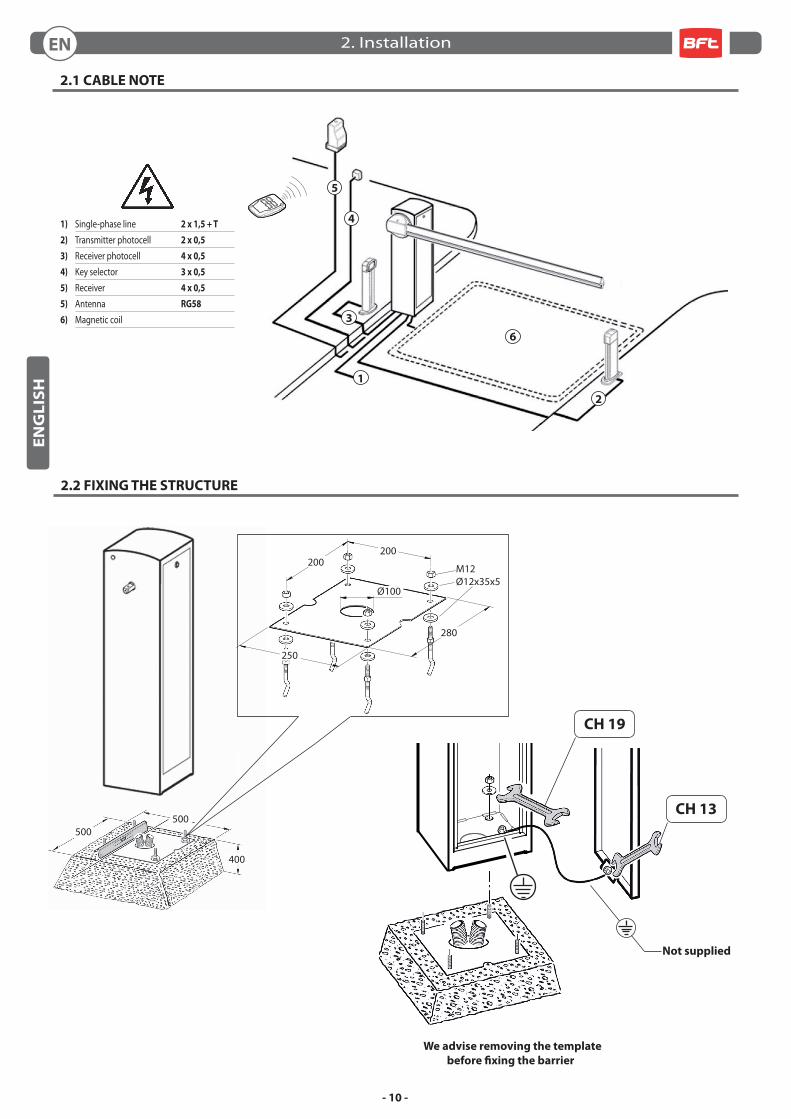
2.1 CABLE NOTE
2.2 FIXING THE STRUCTURE
5
6
3
1
2
4
500500
400
We advise removing the template
before fi xing the barrier
CH 19
CH 13
Not supplied
1) Single-phase line 2 x 1,5 + T
2) Transmitter photocell 2 x 0,5
3) Receiver photocell 4 x 0,5
4) Key selector 3 x 0,5
5) Receiver 4 x 0,5
5) Antenna RG58
6) Magnetic coil
M12Ø12x35x5
200200
250
280
Ø100
2. InstallationEN
- 11 -
EN
GL
ISH
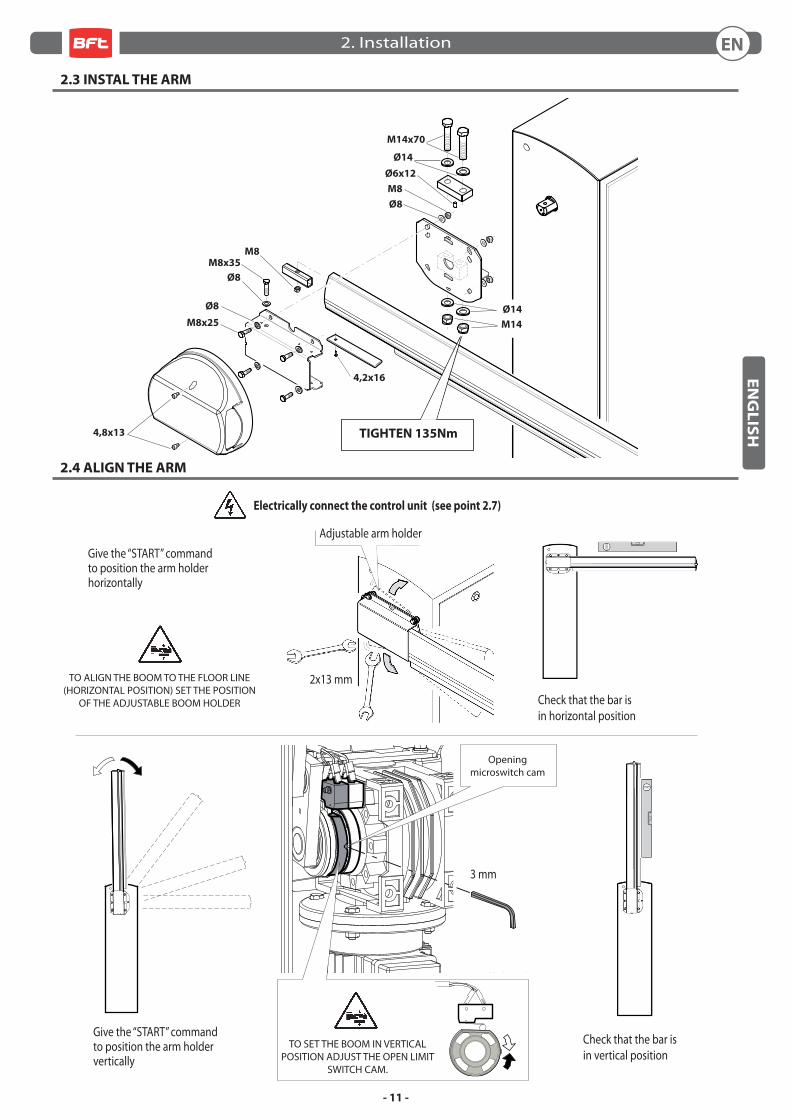
2.3 INSTAL THE ARM
2.4 ALIGN THE ARM
Adjustable arm holder
Electrically connect the control unit (see point 2.7)
TO ALIGN THE BOOM TO THE FLOOR LINE (HORIZONTAL POSITION) SET THE POSITION
OF THE ADJUSTABLE BOOM HOLDER
2x13 mm
Give the “START” commandto position the arm holdervertically
Give the “START” commandto position the arm holderhorizontally
Ø8
M8x25
M8x35
Ø8
M8
Ø6x12
M14x70
Ø8
M8
4,8x13
Ø14
M14
Ø14
TIGHTEN 135Nm
3 mm
Opening microswitch cam
Check that the bar isin horizontal position
Check that the bar isin vertical position
TO SET THE BOOM IN VERTICAL POSITION ADJUST THE OPEN LIMIT
SWITCH CAM.
4,2x16
2. Installation EN
- 12 -
EN
GL
ISH
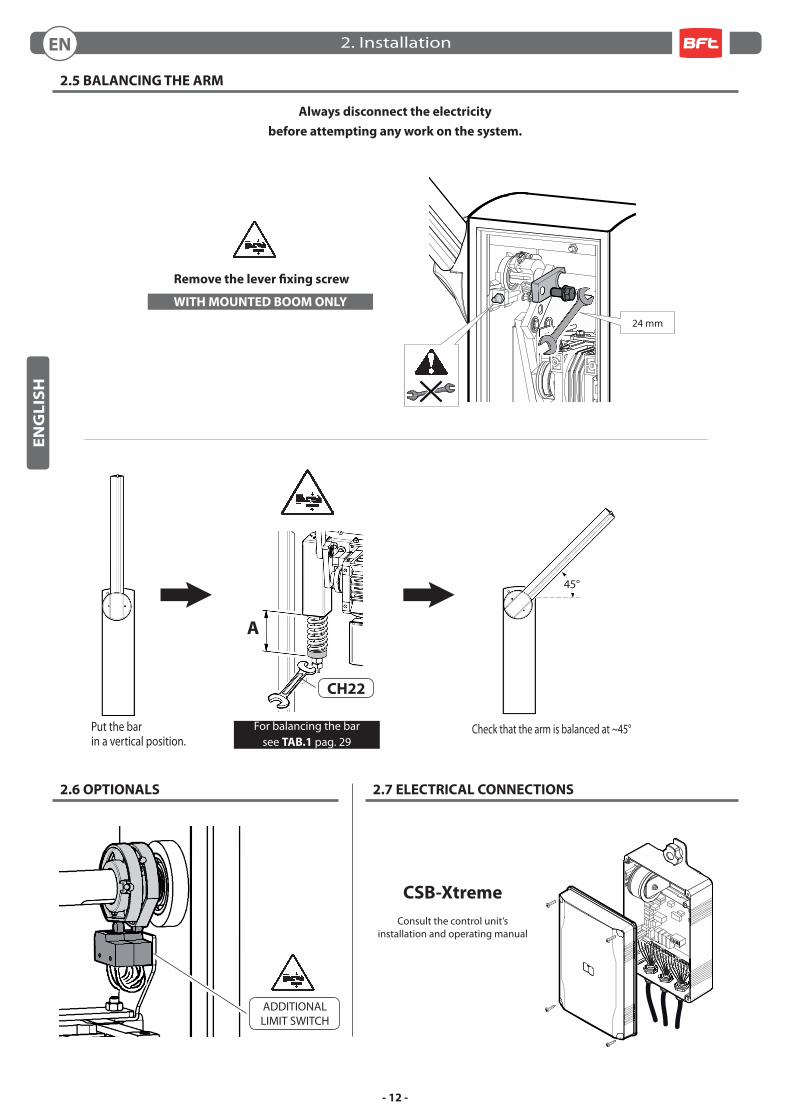
ADDITIONAL LIMIT SWITCH
Consult the control unit’s installation and operating manual
2.6 OPTIONALS 2.7 ELECTRICAL CONNECTIONS
2.5 BALANCING THE ARM
CSB-Xtreme
WITH MOUNTED BOOM ONLY
Remove the lever fi xing screw
A
45°
CH22
Check that the arm is balanced at ~45°For balancing the bar see TAB.1 pag. 29
Always disconnect the electricity
before attempting any work on the system.
Put the barin a vertical position.
24 mm
2. InstallationEN
- 13 -
EN
GL
ISH
3.1 GENERAL SAFETY
• The barrier is designed exclusively for vehicles traffi c; report and delimit any walkways through a special sign. • Keep adults, children and property out of range of the automated system, especially while it is operating.• For safety reasons and to comply with current standards, we recommend using the control unit.• To install follow the instructions given in the enclosed “GENERAL INSTRUCTIONS FOR SAFETY” sheet.• All electrical connections must be done in compliance with current laws.• The installer must instruct the user on how to use the automatism correctly, on the manual emergency manoeuvre and on the possible risks during operation.• Analyse the risks and take all the appropriate measures to eliminate them, as prescribed by the EEC machine directive 2006/42, installing the safety devices.• Always disconnect the electricity before attempting any work on the system with a lockable cut-off switch.
3.2 WARNINGS
Correct controller operation is only ensured when the data contained in the present manual are observed. The Company is not to be held responsible
for any damage resulting from failure to observe the installation standards and the instructions contained in the present manual.
The descriptions and illustrations contained in the present manual are not binding. The Company reserves the right to make any alterations
deemed appropriate for the technical, manufacturing and commercial improvement of the product, while leaving the essential product features
unchanged, at any time and without undertaking to update the present publication.
3.3 USE
• It is essential to follow the instructions given in the enclosed “GENERAL INSTRUCTIONS FOR SAFETY” sheet.• In the case of a manual emergency manoeuvre, follow the indications described in point 3.5.
• Consult the control unit’s installation and operating manual.
3.4 ROUTINE MAINTENANCE (EVERY 6 MONTHS)
• Maintenance must be carried out by qualifi ed personnel only.• Check the condition of the barrier structure.• Check tightness of the arm.• Check the condition of the spring, chain and relative anchorings. • Check arm balance.• Check that at the end of travel the arm is horizontal and/or vertical• Check operation of the control unit and safety devices. • Check operation of the manual emergency manoeuvre.• Record maintenance in the form on the page 30.
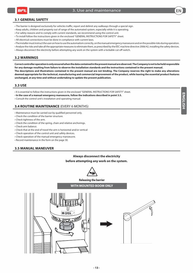
3.5 MANUAL MANEUVER
Always disconnect the electricity
before attempting any work on the system.
Releasing the barrier
WITH MOUNTED BOOM ONLY
3. Use and maintenance EN
- 14 -
FR
AN
ÇA
IS
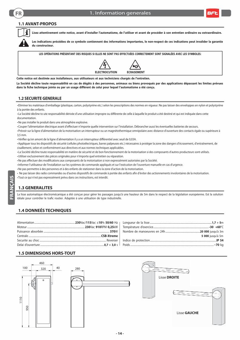
1.5 DIMENSIONS HORS-TOUT
Lisse DROITE
Lisse GAUCHE
1.1 AVANT-PROPOS
Lisez attentivement cette notice, avant d’installer l’automatisme, de l’utiliser et avant de procéder à son entretien ordinaire ou extraordinaire.
Les indications précédées de ce symbole contiennent des informations importantes, le non-respect de ces indications peut invalider la garantie
du constructeur.
LES OPÉRATIONS PRÉSENTANT DES RISQUES SI ELLES NE SONT PAS EFFECTUÉES CORRECTEMENT SONT SIGNALÉES AVEC LES SYMBOLES:
ELECTROCUTION ECRASEMENT
Cette notice est destinée aux installateurs, aux utilisateurs et aux techniciens chargés de l’entretien.
La Société décline toute responsabilité en cas de dégâts à des personnes, animaux ou biens provoqués par des applications dépassant les limites prévues
dans la fi che technique jointe ou par un usage diff érent de celui pour lequel l’automatisme a été conçu.
1.2 SECURITE GENERALE
• Eliminer les matériaux d’emballage (plastique, carton, polystyrène etc.) selon les prescriptions des normes en vigueur. Ne pas laisser des enveloppes en nylon et polystyrène à la portée des enfants.• La Société décline to ute responsabilité dérivée d’une utilisation impropre ou diff érente de celle à laquelle le produit a été destiné et qui est indiquée dans cette documentation.• Ne pas installer le produit dans une atmosphère explosive.• Couper l’alimentation électrique avant d’eff ectuer n’importe quelle intervention sur l’installation. Débrancher aussi les éventuelles batteries de secours.• Prévoir sur la ligne d’alimentation de la motorisation un interrupteur ou un magnétothermique omnipolaire avec distance d’ouverture des contacts égale ou supérieure à 3,5 mm.• Vérifi er qu’en amont de la ligne d’alimentation il y a un interrupteur diff érentiel avec seuil de 0,03A.• Appliquer tous les dispositifs de sécurité (cellules photoélectriques, barres palpeuses etc.) nécessaires à protéger la zone des dangers d’écrasement, d’entraînement, de cisaillement, selon et conformément aux directives et aux normes techniques applicables.• La Société décline toute responsabilité en matière de sécurité et de bon fonctionnement de la motorisation si des composants d’autres producteurs sont utilisés.• Utiliser exclusivement des pièces originales pour n’importe quel entretien ou réparation.• Ne pas eff ectuer des modifi cations aux composants de la motorisation si non expressément autorisées par la Société.• Informer l’utilisateur de l’installation sur les systèmes de commande appliqués et sur l’exécution de l’ouverture manuelle en cas d’urgence.• Ne pas permettre à des personnes et à des enfants de stationner dans la zone d’action de la motorisation.• Ne pas laisser des radio commandes ou d’autres dispositifs de commande à portée des enfants afi n d’éviter des actionnements involontaires de la motorisation.• Tout ce qui n’est pas expressément prévu dans ces instructions, est interdit.
1.3 GENERALITES
La lisse automatique électromécanique a été conçue pour gérer les passages jusqu’à une hauteur de 5m dans le respect de la législation européenne. Est la solution idéale pour contrôler le trafi c routier. Adaptée à une utilisation de type industrielle.
1.4 DONNEÉS TECHNIQUES
Alimentation .............................................................. 230Vac/115Vac ±10% 50/60 HzMoteur ........................................................................................ 230Vac 910RPM 0,25kWPuissance absorbée ..................................................................................................... 370WCentrale ............................................................................................................... CSB-Xtreme
Securite au choc ...................................................................................................... ReverserDelai d’ouverture ..................................................................................................0,7 ÷ 3,0 s
Longueur de la lisse ...............................................................................................1,7 ÷ 5mTempérature d’exercice..................................................................................... -30 +60°CNombre de manoeuvres en 24h .....................................................20 000 jusqu’à 3m 5 000 jusqu’à 5mIndice de protection ......................................................................................................IP 54
Poids ................................................................................................................................~70 kg
460
950
1110
320 28040100
1. Information generalesFR
- 15 -
FR
AN
ÇA
IS
500500
400
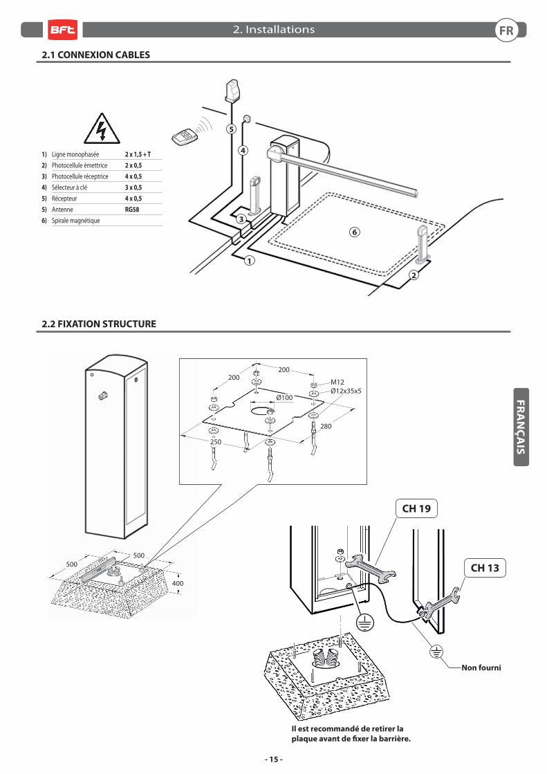
2.1 CONNEXION CABLES
2.2 FIXATION STRUCTURE
5
6
3
1
2
4
Il est recommandé de retirer la
plaque avant de fi xer la barrière.
CH 19
CH 13
Non fourni
1) Ligne monophasée 2 x 1,5 + T
2) Photocellule émettrice 2 x 0,5
3) Photocellule réceptrice 4 x 0,5
4) Sélecteur à clé 3 x 0,5
5) Récepteur 4 x 0,5
5) Antenne RG58
6) Spirale magnétique
M12Ø12x35x5
200200
250
280
Ø100
2. Installations FR
- 16 -
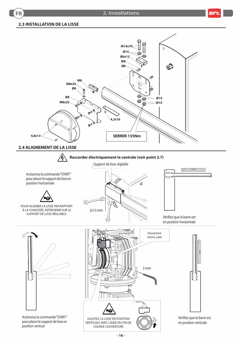
2.3 INSTALLATION DE LA LISSE
2.4 ALIGNEMENT DE LA LISSE
Raccorder électriquement la centrale (voir point 2.7)
Actionnez la commande “START”pour placer le support de lisse enposition vertical
Actionnez la commande “START”pour placer le support de lisse enposition horizontale
POUR ALIGNER LA LISSE PAR RAPPORT À LA CHAUSSÉE, INTERVENIR SUR LE
SUPPORT DE LISSE RÉGLABLE.
Ø8
M8x25
M8x35
Ø8
M8
Ø6x12
M14x70
Ø8
M8
4,8x13
Ø14
M14
Ø14
SERRER 135Nm
Support de lisse réglable
2x13 mm
3 mm
Vérifi ez que la barre esten position horizontale
Vérifi ez que la barre esten position verticale
Ouverturemicro-cam
AJUSTEZ LA LISSE EN POSITION VERTICALE AVEC L’AIDE DU FIN DE
COURSE L’OUVERTURE
4,2x16
2. InstallationsFR
- 17 -
FR
AN
ÇA
IS
MICRO INTERRUPTEUR
ADDITIONEL
Consulter le manuel d’installation et d’utilisation de la centrale
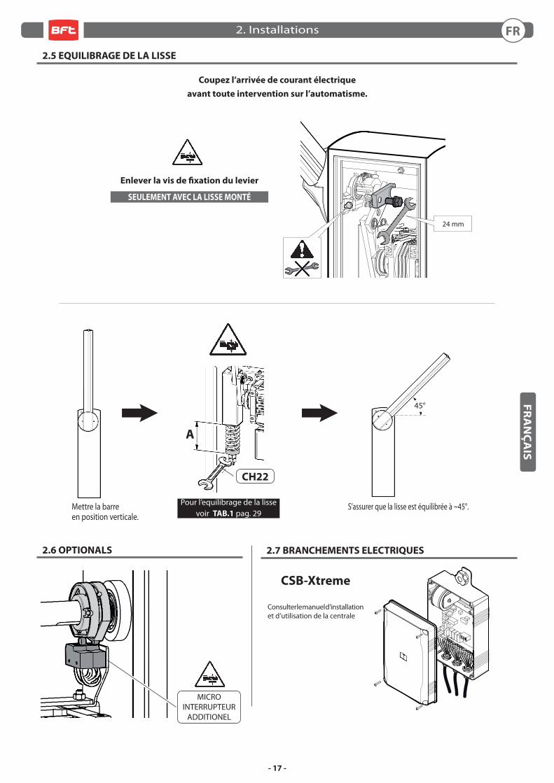
2.6 OPTIONALS 2.7 BRANCHEMENTS ELECTRIQUES
2.5 EQUILIBRAGE DE LA LISSE
CSB-Xtreme
Mettre la barreen position verticale.
SEULEMENT AVEC LA LISSE MONTÉ
Enlever la vis de fi xation du levier
A
45°
CH22
S’assurer que la lisse est équilibrée à ~45°. Pour l’equilibrage de la lisse voir TAB.1 pag. 29
Coupez l’arrivée de courant électrique
avant toute intervention sur l’automatisme.
24 mm
2. Installations FR
- 18 -
FR
AN
ÇA
IS
3.1 SÉCURITÉ GÉNÉRALE
• La barrière est conçu exclusivement pour les véhicules; signaler et délimiter par un signe spécial les allées piétonnes. • Tenez les enfants, les personnes et les objets à l’écart du rayon d’action de l’automatisation, en particulier pendant son fonctionnement.• Pour des raisons de sécurité et d’observation de la législation en vigueur, il est conseillé d’utiliser la centrale de commande. • La pose doit s’eff ectuer selon les prescriptions reportées sur la feuille jointe “REGLES GENERALES DE SECURITE”.• Les branchements électriques doivent être conformes à la législation en vigueur en la matière. • L’installateur doit informer l’utilisateur sur le fonctionnement de l’automatisme, sur la manœuvre manuelle d’arrêt d’urgence et sur les risques liés au fonctionnement. • L’analyse des risques implique la mise sur pied de mesures destinées à éliminer lesdits risques comme le prévoit la directive machines 2006/42/CEE, en installant les dispositifs de sécurité. • Coupez l’arrivée de courant électrique avant toute intervention sur l’automatisme avec un interrupteur verrouillable.
3.2 AVERTISSEMENTS
Le bon fonctionnement de l’actionneur n’est assuré que si les données fournies dans ce manuel sont respectées. Le constructeur ne répond pas
pour les dommages provoqués par le non respect des normes d’installation et des indications fournies dans ce manuel.
Les descriptions et les fi gures de ce manuel n’engagent pas le constructeur. En laissant inaltérées les caractéristiques essentielles du produit, la
Société se réserve le droit d’apporter à n’importe quel moment les modifi cations qu’elle juge opportunes pour améliorer le produit du point de
vue technique, commercial et de construction, sans s’engager à mettre à jour cette publication.
3.3 UTILISATION
• Suivez scrupuleusement les prescriptions reportées sur la feuille jointe “REGLES GENERALES DE SECURITE”.• En cas de manœuvre manuelle d’arrêt d’urgence, suivez les indications décrites au paragraphe 3.5.
• Consulter le manuel d’installation et d’utilisation de la centrale.
3.4 ROUTINE MAINTENANCE (TOUS LES 6 MOIS)
• L’entretien doit être eff ectué seulement par un personnel qualifi é.• Contrôlez la structure de la lisse. • Contrôlez le serrage de la lisse. • Contrôlez l’état du ressort, de la chaîne et des fi xations correspondantes. • Contrôlez l’équilibrage de la lisse.• Contrôlez l’horizontalité et/ou la verticalité de la lisse en fi n de course. • Vérifi ez le fonctionnement de la centrale et des dispositifs de sécurité. • Vérifi ez le fonctionnement de la manœuvre manuelle d’arrêt d’urgence. • Maintenance des enregistrements dans le formulaire sur la page. 30.
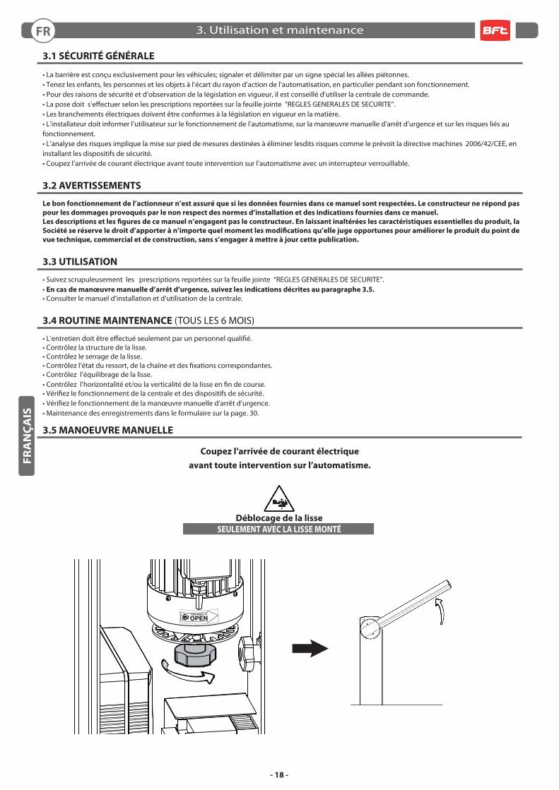
3.5 MANOEUVRE MANUELLE
Coupez l’arrivée de courant électrique
avant toute intervention sur l’automatisme.
Déblocage de la lisse
SEULEMENT AVEC LA LISSE MONTÉ
3. Utilisation et maintenanceFR
- 19 -
DED
EU
TS
CH
1.5 ABMESSUNGEN
RECHTE Schranke
LINKE Schranke
1.1 EINLEITUNG
Das Handbuch ist vor der Installation des Produkts sowie vor der ordentlichen und außerordentlichen Wartung sorgfältig zu lesen.
Die Angaben, denen dieses Symbol vorangestellt ist, enthalten Informationen zu allen möglichen Themen von bes onderer
Bedeutung, ihre Nichtbeachtung kann zum Verlust der vertraglichen Garantie führen.
WENN DIE DURCH FOLGENDE SYMBOLE GEKENNZEICHNETEN EINGRIFFE NICHT KORREKT DURCHGEFÜHRT WERDEN,
KANN ES ZU GEFAHRSITUATIONEN KOMMEN:
STROMSCHLAG QUETSCHUNG
Das INSTALLATIONS, BETRIEBS UND WARTUNGSHANDBUCH ist für die Installateure, Anwender und Wartungsfachmänner bestimmt.
Der Hersteller haftet nicht für Personen, Tier oder Sachschäden, die auf eine unsachgemäße Anwendung des Produkts sowie auf das Überschreiten
der im technischen Blatt angegebenen Grenzwerte zurückzuführen sind.
1.2 ALLGEMEINE SICHERHEITSHINWEISE
• Verpackungsmaterialien (Plastik, Karton, Polystyrol u. a.) sind nach den einschlägigen Vorschriften zu entsorgen. Keine Nylon-oder Polystyroltüten in Reichweite von Kindern liegenlassen.• Der Hersteller lehnt jede Verantwortung für Folgen ab, die durch den unsachgemäßen oder nicht bestimmungsgemäßen, weil in dieser Doku-mentation nicht genannten Gebrauch entstehen.• Die Anlage darf nicht in explosionsgefährdeter Atmosphäre installiert werden.• Vor jedem Eingriff an der Anlage die Stromversorgung unterbrechen. Auch Puff erbatterien abklemmen, falls vorhanden.• Versehen Sie die Versorgungsleitung der Anlage mit einem Schalter oder allpoligen magnetthermischen Schutzschalter mit einem Kontaktabstand von mindestens 3,5 mm.• Der Versorgungsleitung muß ein Fehlerstromschutzschalter mit einer Schwelle von 0,03A vorgeschaltet sein.• Alle Sicherheitsvorrichtungen (Fotozellen, Sicherheitsleisten u. a.) anbringen, die verhindern, daß sich im Torbereich jemand quetscht, schneidet oder mitgerissen wird.• Der Hersteller lehnt jede Verantwortung für die Sicherheit und die Funkti onstüchtigkeit der Anlage ab, wenn Komponenten anderer Produzenten verwendet werden.• Für Wartungen und Reparaturen ausschließlich Originalteile verwenden.• Keine Umbauten an Anlagenkomponenten vornehmen, wenn sie nicht ausdrücklich vom Hersteller genehmigt wurden.• Weisen Sie den Anlagennutzer in die vorhandenen Steuerungssysteme und die manuelle Toröff nung im Notfall ein.• Kindern oder Erwachsenen ist es nicht gestattet, im Aktionsbereich der Anlage zu verweilen.• Keine Fernbedienungen oder andere Steuerungsvorrichtungen in Reichweite von Kindern liegenlassen. Sie könnten die Anlage versehentlich in Gang setzen.• Alles, was nicht ausdrücklich in dieser Anleitung genannt ist, ist untersagt.
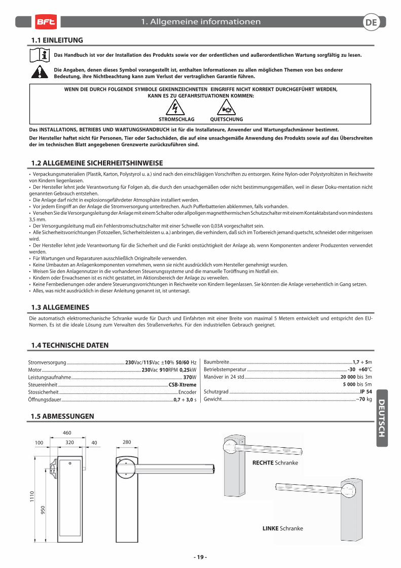
1.3 ALLGEMEINES
Die automatisch elektromechanische Schranke wurde für Durch und Einfahrten mit einer Breite von maximal 5 Metern entwickelt und entspricht den EU-Normen. Es ist die ideale Lösung zum Verwalten des Straßenverkehrs. Für den industriellen Gebrauch geeignet.
1.4 TECHNISCHE DATEN
Stromversorgung ..................................................... 230Vac/115Vac ±10% 50/60 HzMotor ........................................................................................... 230Vac 910RPM 0,25kWLeistungsaufnahme ...................................................................................................... 370WSteuereinheit ..................................................................................................... CSB-Xtreme
Stossicherheit ............................................................................................................. EncoderÖff nungsdauer .......................................................................................................0,7 ÷ 3,0 s
Baumbreite .................................................................................................................1,7 ÷ 5mBetriebstemperatur ............................................................................................ -30 +60°CManöver in 24 std ........................................................................................20 000 bis 3m 5 000 bis 5mSchutzgrad ........................................................................................................................IP 54
Gewicht ...........................................................................................................................~70 kg
460
950
1110
320 28040100
1. Allgemeine informationen
- 20 -
DED
EU
TS
CH 500
500
400
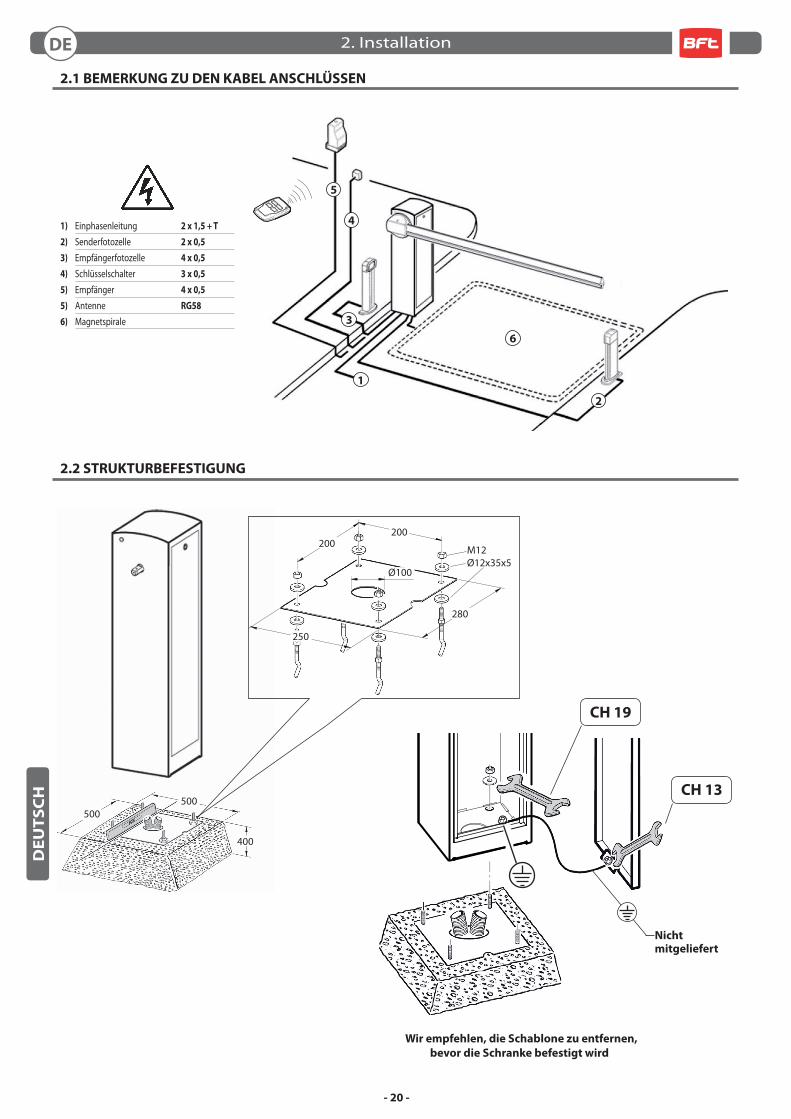
2.1 BEMERKUNG ZU DEN KABEL ANSCHLÜSSEN
2.2 STRUKTURBEFESTIGUNG
5
6
3
1
2
4
Wir empfehlen, die Schablone zu entfernen,
bevor die Schranke befestigt wird
CH 19
CH 13
Nichtmitgeliefert
1) Einphasenleitung 2 x 1,5 + T
2) Senderfotozelle 2 x 0,5
3) Empfängerfotozelle 4 x 0,5
4) Schlüsselschalter 3 x 0,5
5) Empfänger 4 x 0,5
5) Antenne RG58
6) Magnetspirale
M12Ø12x35x5
200200
250
280
Ø100
2. Installation
- 21 -
DED
EU
TS
CH
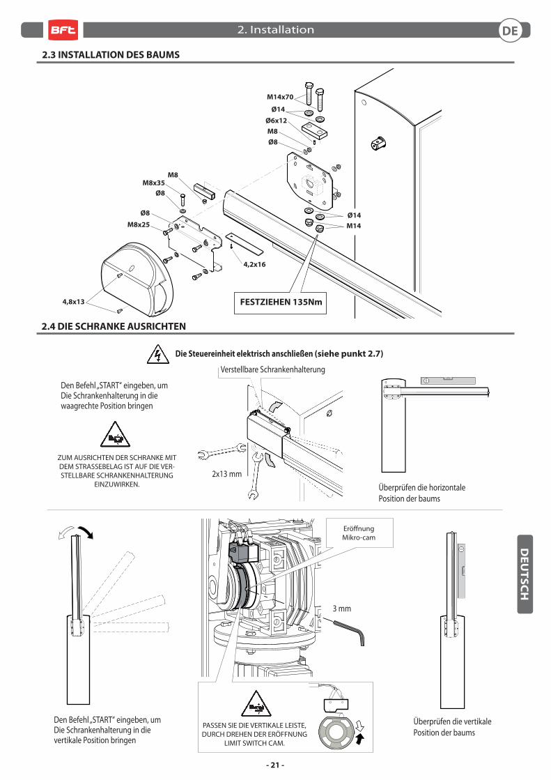
2.3 INSTALLATION DES BAUMS
2.4 DIE SCHRANKE AUSRICHTEN
Die Steuereinheit elektrisch anschließen (siehe punkt 2.7)
Den Befehl „START“ eingeben, umDie Schrankenhalterung in diewaagrechte Position bringen
Den Befehl „START“ eingeben, umDie Schrankenhalterung in die vertikale Position bringen
ZUM AUSRICHTEN DER SCHRANKE MIT DEM STRASSEBELAG IST AUF DIE VER-STELLBARE SCHRANKENHALTERUNG
EINZUWIRKEN.
Ø8
M8x25
M8x35
Ø8
M8
Ø6x12
M14x70
Ø8
M8
4,8x13
Ø14
M14
Ø14
FESTZIEHEN 135Nm
Verstellbare Schrankenhalterung
2x13 mm
3 mm
Eröff nungMikro-cam
Überprüfen die horizontalePosition der baums
Überprüfen die vertikalePosition der baums
PASSEN SIE DIE VERTIKALE LEISTE, DURCH DREHEN DER ERÖFFNUNG
LIMIT SWITCH CAM.
4,2x16
2. Installation
- 22 -
DED
EU
TS
CH
ENDSCHALTER ZUSÄTZLICH
Die Installations und Bedienungsanleitungen der Steuereinheit nachschlagen.
2.6 OPTIONALS 2.7 ELEKTRISCHE ANSCHLÜSSE
2.5 AUSBILANCIERUNG DES BAUMES
CSB-Xtreme
NUR MIT MONTIERTEM BAUM AUSFÜHREN
Entfernen Sie den Hebel, Befestigungsschrauben
A
45°
CH22
Überprüfen, dass die Schranke in der ~45° -Stellung ausgeglichen ist.
Ausgleich der Bar fi nden Sie unter TAB.1 pag. 29
Vor jeglichen Eingriff en an der Anlage
ist die Stromversorgung zu unterbrechen.
Die Bar zu setzenin einer senkrechten Position.
24 mm
2. Installation
- 23 -
DED
EU
TS
CH
3.1 ALLGEMEINE SICHERHEIT
• Die Schranke ist ausschließlich für den Fahrzeugverkehr vorgesehen; ein eventueller Fußgängerverkehr ist durch ein geeignetes Schild auszuweisen bzw. einzuschränken. • Halten Sie Kinder, Personen und Sachen aus dem Wirkungsbereich der Automatisierung fern, vor allem während des Betriebs • Aus Sicherheitsgründen und zum Einhalten der anwendbaren Gesetze wird empfohlen, die spezielle Steuereinheit von zu verwenden.• Bei der Installation sind die im beiliegenden Blatt “ALLGEMEINE SICHERHEITSHINWEISE” enthaltenen Vorschriften zu befolgen.• Beim Anschluss an die Stromversorgung sind die geltenden Gesetze zu befolgen.• Der Installateur hat den Anwender bezüglich des korrekten Betriebs des Automatismus, der manuellen Bedienung bei Störungen und Notfällen sowie bezüglich der möglichen Gefahren während des Betriebs zu unterrichten.• Es ist eine Gefahrenanalyse durchzuführen und es sind geeignete Maßnahmen zum Eliminieren der Gefahren zu treff en, wie von der Maschinenrichtlinie 2006/42/EWG vorgeschrieben, wobei auch der Schub einreguliert und die erforderlichen Sicherheitsvorrichtungen installiert werden müssen.• Vor jeglichen Eingriff en an der Anlage ist die Stromversorgung mit einen Schlüssel-Trennschalter zu unterbrechen.
3.2 HINWEISE
Der einwandfreie Betrieb des Antriebes ist nur dann garantiert, wenn die Angaben aus diesem Handbuch beachtet werden. Der Hersteller haftet
nicht für Schäden, die durch Mißachtung der Installationsanweisungen und der Angaben aus diesem Handbuch entstehen.
Die Beschreibungen und bildlichen Darstellungen in diesem Handbuch sind unverbindlich. Der Hersteller behält sich - ohne auch zur Aktualisie-
rung dieser Unterlagen verpfl ichtet zu sein - jederzeit vor, Änderungen vornehmen, wenn er diese für technische oder bauliche Verbesserungen
als notwendig erachtet und die wesentlichen Produkteigenschaften unverändert bleiben.
3.3 BETRIEB
• Die in dem beigestellten Blatt “ALLGEMEINE SICHERHEITSVOR-SCHRIFTEN” enthaltenen Anleitungen sind strikt zu befolgen.• Beim manuellen Bedienung bei Störungen und Notfällen sind die unter Punkt 3.5 beschriebenen Anleitungen zu beachten.
• Die Installations und Bedienungsanleitungen der Steuereinheit nachschlagen.
3.4 ORDENTLICHE WARTUNG (ALLE 6 MONATE)
• Die Wartung hat ausschließlich durch Fachpersonal zu erfolgen.• Zustand der Schrankenstruktur überprüfen.• Kontrollieren, dass der Baum korrekt befetsigt ist.• Zustand der Feder, der Kette und der entsprechenden Verankerungen überprüfen. • Ausbilancierung des Baumes überprüfen.• Kontrollieren, dass der Baum am Endanschlag waagerecht oder senkrecht ist.• Funktionstüchtigkeit der Steuereinheit und der Sicherheitsvorrichtungen überprüfen. • Funktionstüchtigkeit des manuellen Bedienung bei Störungen und Notfällen überprüfen.• Aufzeichnungen in das Formular auf der Seite 30.
3.5 MANUELLES MANÖVRIEREN
Vor jeglichen Eingriff en an der Anlage
ist die Stromversorgung zu unterbrechen.
Schranke entsperren
NUR MIT MONTIERTEM BAUM AUSFÜHREN
3. Gebrauchs und Wartungsanleitungen
- 24 -
ESE
SP
AÑ
OL
1.5 MEDIDAS
Barrera DERECHA
Barrera IZQUIERDA
1.1 INTRODUCCIÓN
Leer detenidamente el folleto antes de instalar el producto, utilizarlo y efectuar el mantenimiento ordinario o extraordinario.
Las indicaciones precedidas por este símbolo contienen informaciones sobre cualquier asunto de importancia particular, no
respetarlas puede comportar la perdida de la garantía contractual.
LAS OPERACIONES QUE, SI NO SON EFECTUADAS CORRECTAMENTE, PUEDEN CONLLEVAR RIESGOS,
VIENEN INDICADAS CON LOS SÍMBOLOS:
ELECTROCUCIÓN APLASTAMIENTO
El folleto de INSTALACIÓN, USO Y MANTENIMIENTO se destina a instaladores, usuarios y operadores de mantenimiento.
La Empresa no es responsable de daños causados a personas, animales o cosas, debidos a aplicaciones que superen los límites indicados en
la fi cha técnica adjunta o debidos a utilización diferente de aquella apra la cual el producto fue proyectado.
1.2 SEGURIDAD GENERAL
• Eliminar los materiales de embalaje (plástico, cartón, poliestireno, etc.) según lo previsto por las normas vigentes. No dejar bolsas de nylon o poliestireno al alcance de los niños.• La Empresa declina toda responsabilidad que derive del uso impropio del producto o de un uso distinto de aquél para el que está destinado y que aparece indicado en la presente documentación.• No instalar el producto en atmósfera explosiva.• Cortar el suministro de corriente antes de efectuar cualquier intervención en la instalación. Desconectar también eventuales baterías tampón, si las hay.• Prever, en la red de alimentación del automatismo, un interruptor o un magnetotérmico omnipolar con una distancia de abertura de los contactos igual o superior a 3,5 mm.• Verifi car que, antes de la red de alimentación, haya un interruptor diferencial con un umbral de 0,03A.• Aplicar todos los dispositivos de seguridad (fotocélulas, barras sensibles, etc.) necesarios para proteger el área del peligro de aplastamiento, transporte o cizallado, de conformidad con las directivas y normas técnicas vigentes.• La Empresa declina toda responsabilidad, a efectos de la seguridad y del buen funcionamiento del automatismo, si se emplean componentes de otros fabricantes.• Usar exclusivamente partes originales al realizar cualquier operación de mantenimiento o reparación.• No modifi car ningún componente del automatismo si antes no se ha sido expresamente autorizado por la Empresa.• Instruir al usuario del equipo sobre los sistemas de mando aplicados y la ejecución de la apertura manual en caso de emergencia.• No permitir que personas o niños estacionen en el campo de acción del automatismo.• No dejar radiomandos u otros dispositivos de mando al alcance de los niños, para evitar el accionamiento involuntario del automatismo.• Todo lo que no está expresamente previsto en estas instrucciones no está permitido.
1.3 GENERALIDAD
La barrera automática electromecánica ha sido diseñada para controlar pasos con ancho de hasta 5 metros, según las normas europeas. Es la solución ideal para la gestión del tráfi co de vehiculos. Es apta para una utilización de tipo industrial
1.4 DATOS TÉCNICOS
Alimentación ............................................................. 230Vac/115Vac ±10% 50/60 HzMotor ........................................................................................... 230Vac 910RPM 0,25kWPotencia absorbida ...................................................................................................... 370WCentralita ............................................................................................................. CSB-Xtreme
Seguridad al choque ............................................................................................... EncoderTiempo de apertura .............................................................................................0,7 ÷ 3,0 s
Longitud barra ..........................................................................................................1,7 ÷ 5mTemp. de operación ........................................................................................... -30 +60°CManiobras en 24h ...................................................................................20 000 hasta 3m 5 000 hasta 5mGrado de protección .....................................................................................................IP 54
Peso ..................................................................................................................................~70 kg
460
950
1110
320 28040100
1. Informaciones generales
- 25 -
ESE
SP
AÑ
OL
500500
400
2.1 NOTA CABLES
2.2 FIJACIÓN ESTRUCTURA
5
6
3
1
2
4
Aconsejamos quitar la plantilla antes
de fi jar la barrera
CH 19
CH 13
Nosuministrada
1) Línea monofásica 2 x 1,5 + T
2) Fotocélula transmisor 2 x 0,5
3) Fotocélula receptor 4 x 0,5
4) Selector de llave 3 x 0,5
5) Receptor 4 x 0,5
5) Antena RG58
6) Espiral magnética
M12Ø12x35x5
200200
250
280
Ø100
2. Instalaciòn
- 26 -
ESE
SP
AÑ
OL
2.3 INSTALACIÒN DE LA BARRA
2.4 ALINEAR LA BARRA
Conectar eléctricamente la centralita (ver punto 2.7)
Dar el comando “START” paracolocar el portabarra en posción horizontal
Dar el comando “START” paracolocar el portabarra en posción vertical
PARA ALINEAR LA BARRA CON LA CALZADA, ACTUAR SOBRE EL PORTABARRA REGULABLE.
Ø8
M8x25
M8x35
Ø8
M8
Ø6x12
M14x70
Ø8
M8
4,8x13
Ø14
M14
Ø14
APRETAR 135Nm
Portabarra regolabile
2x13 mm
3 mm
Aperturamicro-cam
Compruebe que la barra estéen posición horizontal
Compruebe que la barra estéen posición vertical
AJUSTAR EL MASTIL EN VERTICAL UTILIZANDO EL FINAL DE CARRERA
DE APERTURA
4,2x16
2. Instalaciòn
- 27 -
ESE
SP
AÑ
OL
FIN DE CARRERA ADICIONAL
Consultar el manual de instalación y uso de la
centralita
2.6 OPTIONALS 2.7 CONEXIONES ELÉCTRICAS
2.5 EQUILIBRADO DE LA BARRA
CSB-Xtreme
Baja la barraen posición vertical.
HACER SÓLO CON BARRA MONTADA
Quite el tornillo de fi jación palanca
A
45°
CH22
Comprobar que la barraesté equilibrada a ~45°.
Para equilibrar la barra verTAB.1 pag. 29
Antes de cualquier operación en la instalación,
cortar la alimentación eléctrica.
24 mm
2. Instalaciòn
- 28 -
ESE
SP
AÑ
OL
3.1 SEGURIDAD GENERAL
• La barrera está diseñada exclusivamente para el passaje vehicular, informar y delimitar el pasaje peatonal a través de una señal especial. • Mantener a niños, personas y cosas fuera del radio de acción de la automatización, especialmente durante su funcionamiento.• Por razones de seguridad y para respetar las normas vigentes se aconseja utilizar la correspondiente centralita de control.• La instalación debe efectuarse siguiendo las prescripciones presentadas en la hoja adjunta“ADVERTENCIAS GENERALES PARA LA SEGURIDAD”.• Las conexiones eléctricas deben efectuarse cumpliendo las disposiciones de ley vigentes.• El instalador debe instruir al usuario sobre el funcionamiento correcto del automatismo, maniobra manual de emergencia y posibles riesgos durante el funcionamiento.• Efectuar el análisis de riesgos tomando las oportunas medidas para eliminarlos, como prescrito por la directiva máquina 2006/42/CEE, instalando los dispositivos de seguridad.• Antes de cualquier operación en la instalación, cortar la alimentación eléctrica con un interruptor seccionador.
3.2 ADVERTENCIAS
El buen funcionamiento del operador resulta garantizado únicamente si se respetan los datos contenidos en este manual de instrucciones. La
empresa no responde de los daños causados por el incumplimiento de las normas de instalación y de las indicaciones contenidas en este manual.
Las descripciones y las ilustraciones del presente manual tienen un carácter puramente indicativo. Dejando inalteradas las características esen-
ciales del producto, la Empresa se reserva la posibilidad de aportar, en cualquier momento, las modifi caciones que considere convenientes para
mejorar técnica, constructiva y comercialmente el producto, sin la obligación de poner al día esta publicación.
3.3 USO
• Seguir tajantemente las indicaciones presentadas en la hoja adjunta “ADVERTENCIAS GENERALES PARA LA SEGURIDAD”.• En caso de maniobra manual de emergencia seguir las indicaciones del punto 3.5.
• Consultar el manual de instalación y uso de la centralita.
3.4 MANTENIMIENTO ORDINARIO (CADA 6 MESES)
• El mantenimiento debe ser efectuado sólo por personal cualifi cado.• Comprobar el estado de la estructura de la barrera.• Comprobar el estado del apriete de la barra.• Comprobar el estado del muelle, de la cadena y correspondientes fi jaciones. • Comprobar el equilibrio de la barra.• Comprobar que a tope de carrera la barra quede horizontal y/o vertical• Verifi car el funcionamiento de la centralita y de los dispositivos de seguridad. • Verifi car el funcionamiento de la maniobra manual de emergencia.• Mantenimiento de registros en el formulario de la página 30.
3.5 MANIOBRA MANUAL
Antes de cualquier operación en la instalación,
cortar la alimentación eléctrica.
Desbloqueo barrera
HACER SÓLO CON BARRA MONTADA
3. Uso y mantenimiento
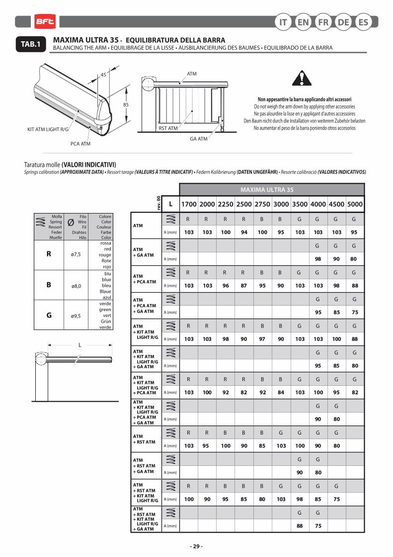
- 29 -
Non appesantire la barra applicando altri accessori
Do not weigh the arm down by applying other accessoriesNe pas alourdire la lisse en y appliqant d’autres accessoires
Den Baum nicht durch die Installation von weiterem Zubehör belastenNo aumentar el peso de la barra poniendo otros accesorios
85
45
TAB.1
MollaSpring
RessortFeder
Muelle
FiloWire
FilDrahtes
Hilo
ColoreColor
CouleurFarbeColor
ø7,5
rossared
rougeRoterojo
B
R
ø8,0
blubluebleu
Blaueazul
G ø9,5
verdegreen
vertGrün
verde
Ø
L
Taratura molle (VALORI INDICATIVI)Springs calibration (APPROXIMATE DATA) • Ressort tarage (VALEURS À TITRE INDICATIF) • Federn Kalibrierung (DATEN UNGEFÄHR) • Resorte calibració (VALORES INDICATIVOS)
ESDEFRENIT
R R R R B G G G G
G G G
B
R R R R B B G G G G
G G G
R R R R B G G G G
G G G
B
R R R R B G G G GB
G G
R R B B B G G GG
G G
R R B B B G G G
G G
G
MAXIMA ULTRA 35
1700 2000 2250 2500 2750 3500 4000 4500 5000
ATM
A (mm) 103 103 100 94 100 103 103 103 95
ATM
+ GA ATMA (mm)
3000
95
98 90 80
ATM
+ PCA ATMA (mm) 103 103 96 87 95 103 103 98 88
ATM
+ PCA ATM
+ GA ATM A (mm)
90
95 85 75
ATM
+ KIT ATM
LIGHT R/G
+ KIT ATM
LIGHT R/G
+ KIT ATM
LIGHT R/G
+ KIT ATM LIGHT R/G
+ KIT ATM LIGHT R/G
+ KIT ATM LIGHT R/G
A (mm) 103 103 98 90 97 103 103 100 88
ATM
+ GA ATM A (mm) 95 85 80
ATM
+ PCA ATM A (mm) 103 100 92 82 92
90
84 103 100 95 82
ATM
+ PCA ATM
+ GA ATMA (mm) 90 80
ATM
+ RST ATMA (mm) 103 95 100 90 85 103 100 90 80
ATM
+ RST ATM
+ GA ATM A (mm) 90 80
ATM
+ RST ATM
A (mm) 100 90 95 85 80 98 85 75
ATM
+ RST ATM
+ GA ATMA (mm)
103
88 75
L
rev
. 0
0
MAXIMA ULTRA 35 • EQUILIBRATURA DELLA BARRA BALANCING THE ARM • EQUILIBRAGE DE LA LISSE • AUSBILANCIERUNG DES BAUMES • EQUILIBRADO DE LA BARRA
KIT ATM LIGHT R/G
PCA ATMGA ATM
RST ATM
ATM

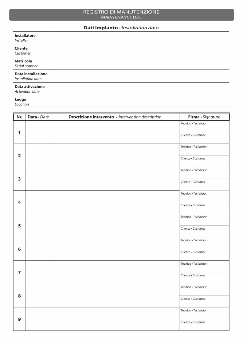
Dati impianto • Installation data
Installatore
Installer
Cliente
Customer
Matricola
Serial number
Data installazione
Installation date
Data attivazione
Activation date
Luogo
Location
Nr. Data • Date Descrizione intervento • Intervention description Firma • Signature
1
Tecnico • Technician
Cliente • Customer
2
Tecnico • Technician
Cliente • Customer
3
Tecnico • Technician
Cliente • Customer
4
Tecnico • Technician
Cliente • Customer
5
Tecnico • Technician
Cliente • Customer
6
Tecnico • Technician
Cliente • Customer
7
Tecnico • Technician
Cliente • Customer
8
Tecnico • Technician
Cliente • Customer
9
Tecnico • Technician
Cliente • Customer
REGISTRO DI MANUTENZIONEMAINTENANCE LOG
INSTALLATOREINSTALLERINSTALLATEURINSTALLATEURINSTALATOR