Fw 3610731076
5
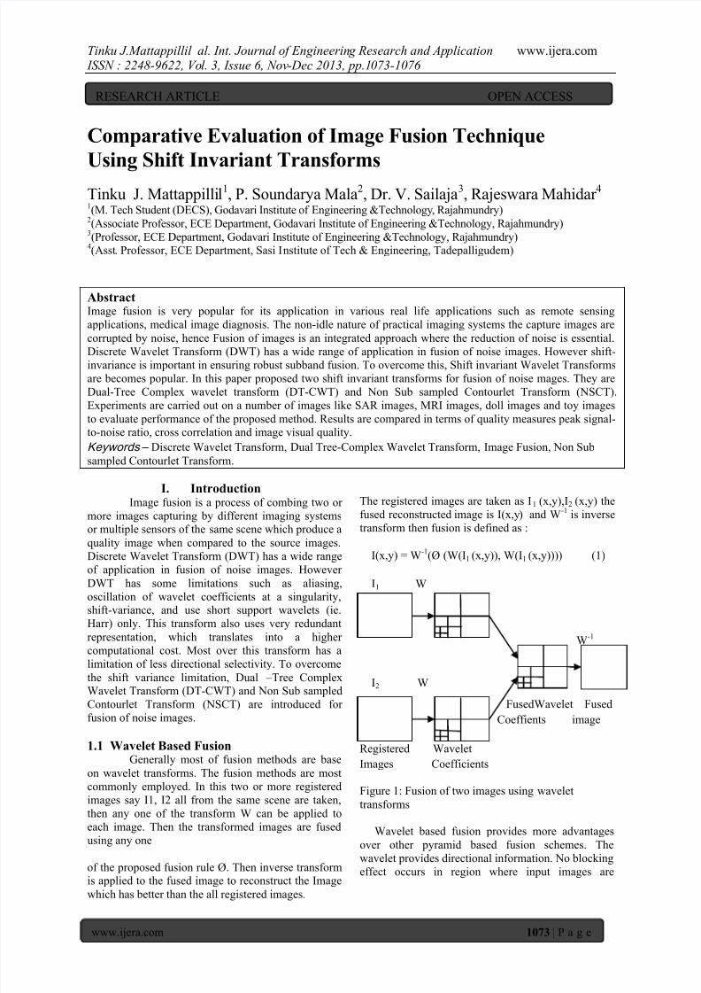
Tinku J.Mattappillil al. Int. Journal of Engineerin g Research and Ap plication www.ijera.com ISSN : 2248-9622, Vo l. 3, Issue 6, Nov -Dec 2013, pp.1 073-1076 www.ijera.com 1073 | Page Comparative Evaluation of Image Fusion Technique Using Shift Invariant Transforms Tinku J. Mattappilli l 1 , P. Soundarya Mala 2 , Dr. V. Sailaja 3 , Rajeswara Mahidar 4 1 (M. Tech Student (DECS), Godavari Institute of Engineering &Technology , Rajahmundry) 2 (Associate Professor, ECE Department, Godavari Institute of Engineering &Technology, Rajahmundry) 3 (Professor, ECE Department, Godavari Institute of Engineering &Technology, Rajahmundry) 4 (Asst . Professor, ECE Department, Sasi I nstitute of Tech & Engineering, Tadepalligudem) Abstract Image fusion is very popular for its application in various real life applications such as remote sensing applications, medical image diagnosis. The non-idle nature of practical imaging systems the capture images are corrupted by noise, hence Fusion of images is an integrated approach where the reduction of noise is essential. Discrete Wavelet Transform (DWT) has a wide range of application in fusion of noise images. However shift- invariance is important in ensuring robust subband fusion. To overcome this, Shift invariant Wavelet Transforms are becomes popular. In this paper proposed two shift invariant transforms for fusion of noise mages. They are Dual-Tree Complex wavelet transform (DT-CWT) and Non Sub sampled Contourlet Transform (NSCT). Experiments are carried out on a number of images like SAR images, MRI images, doll images and toy images to evaluate performance of the proposed method. Results are compared in terms of quality measures peak signal- to-noise ratio, cross correlation and image visual quality. Keywords – Discrete Wavelet Transform, Dual Tree-Complex Wavelet Transform, Image Fusion, Non Sub sampled Contourlet Transform. I. Introduction Image fusion is a process of combing two or more images capturing by different imaging systems or multiple sensors of the same scene which produce a quality image when compared to the source images. Discrete Wavelet Transform (DWT) has a wide range of application in fusion of noise images. However DWT has some limitations such as aliasing, oscillation of wavelet coefficients at a singularity, shift-variance, and use short support wavelets (ie. Harr) only. This transform also uses very redundant representation, which translates into a higher computational cost. Most over this transform has a limitation of less directional selectivity. To overcome the shift variance limitation, Dual – Tree Complex Wavelet Transform (DT-CWT) and Non Sub sampled Contourlet Transform (NSCT) are introduced for fusion of noise images. 1.1 Wavelet Based Fusion Generally most of fusion methods are base on wavelet transforms. The fusion methods are most commonly employed. In this two or more registered images say I1, I2 all from the same scene are taken, then any one of the transform W can be applied to each image. Then the transformed images are fused using any one of the proposed fusion rule Ø. Then inverse transform is applied to the fused image to reconstruct the Image which has better than the all registered images. The registered images are taken as I 1 (x,y),I 2 (x,y) the fused reconstructed image is I(x,y ) and W -1 is inverse transform then fusion is defined as : I(x,y) = W -1 (Ø (W(I 1 (x,y)), W(I 1 (x,y)))) (1) I 1 W W -1 I 2 W FusedWavelet Fused Coeffients image Registered Wavelet Images Coefficients Figure 1: Fusion of two images using wavelet transforms Wavelet based fusion provides more advantages over other pyramid based fusion schemes. The wavelet provides directional information. No blocking effect occurs in region where input images are RESEARCH ARTICLE OPEN ACCESS
-
Upload
anonymous-7vppkws8o -
Category
Documents
-
view
216 -
download
0
Transcript of Fw 3610731076
8/13/2019 Fw 3610731076
http://slidepdf.com/reader/full/fw-3610731076 1/4
Tinku J.Mattappillil al. Int. Journal of Engineering Research and Application www.ijera.com ISSN : 2248-9622, Vol. 3, Issue 6, Nov-Dec 2013, pp.1073-1076
www.ijera.com 1073 | P a g e
Comparative Evaluation of Image Fusion Technique
Using Shift Invariant Transforms
Tinku J. Mattappillil1, P. Soundarya Mala2, Dr. V. Sailaja3, Rajeswara Mahidar 4 1(M. Tech Student (DECS), Godavari Institute of Engineering &Technology, Rajahmundry)
2(Associate Professor, ECE Department, Godavari Institute of Engineering &Technology, Rajahmundry)
3(Professor, ECE Department, Godavari Institute of Engineering &Technology, Rajahmundry)
4(Asst. Professor, ECE Department, Sasi Institute of Tech & Engineering, Tadepalligudem)
AbstractImage fusion is very popular for its application in various real life applications such as remote sensing
applications, medical image diagnosis. The non-idle nature of practical imaging systems the capture images are
corrupted by noise, hence Fusion of images is an integrated approach where the reduction of noise is essential.
Discrete Wavelet Transform (DWT) has a wide range of application in fusion of noise images. However shift-invariance is important in ensuring robust subband fusion. To overcome this, Shift invariant Wavelet Transforms
are becomes popular. In this paper proposed two shift invariant transforms for fusion of noise mages. They are
Dual-Tree Complex wavelet transform (DT-CWT) and Non Sub sampled Contourlet Transform (NSCT).
Experiments are carried out on a number of images like SAR images, MRI images, doll images and toy images
to evaluate performance of the proposed method. Results are compared in terms of quality measures peak signal-to-noise ratio, cross correlation and image visual quality.
Keywords – Discrete Wavelet Transform, Dual Tree-Complex Wavelet Transform, Image Fusion, Non Sub
sampled Contourlet Transform.
I. IntroductionImage fusion is a process of combing two or
more images capturing by different imaging systemsor multiple sensors of the same scene which produce a
quality image when compared to the source images.
Discrete Wavelet Transform (DWT) has a wide range
of application in fusion of noise images. However
DWT has some limitations such as aliasing,
oscillation of wavelet coefficients at a singularity,shift-variance, and use short support wavelets (ie.
Harr) only. This transform also uses very redundant
representation, which translates into a higher
computational cost. Most over this transform has a
limitation of less directional selectivity. To overcome
the shift variance limitation, Dual – Tree Complex
Wavelet Transform (DT-CWT) and Non Sub sampledContourlet Transform (NSCT) are introduced for
fusion of noise images.
1.1 Wavelet Based Fusion
Generally most of fusion methods are base
on wavelet transforms. The fusion methods are most
commonly employed. In this two or more registered
images say I1, I2 all from the same scene are taken,
then any one of the transform W can be applied to
each image. Then the transformed images are fused
using any one
of the proposed fusion rule Ø. Then inverse transformis applied to the fused image to reconstruct the Image
which has better than the all registered images.
The registered images are taken as I1 (x,y),I2 (x,y) the
fused reconstructed image is I(x,y) and W-1
is inverse
transform then fusion is defined as :
I(x,y) = W-1
(Ø (W(I1 (x,y)), W(I1 (x,y)))) (1)
I1 W
W-1
I2 W
FusedWavelet Fused
Coeffients image
Registered Wavelet
Images Coefficients
Figure 1: Fusion of two images using wavelet
transforms
Wavelet based fusion provides more advantages
over other pyramid based fusion schemes. The
wavelet provides directional information. No blocking
effect occurs in region where input images are
RESEARCH ARTICLE OPEN ACCESS
8/13/2019 Fw 3610731076
http://slidepdf.com/reader/full/fw-3610731076 2/4
Tinku J.Mattappillil al. Int. Journal of Engineering Research and Application www.ijera.com ISSN : 2248-9622, Vol. 3, Issue 6, Nov-Dec 2013, pp.1073-1076
www.ijera.com 1074 | P a g e
significantly different. Wavelet based fusion gives
better signal-to-noise ratio.
II. Dual-Tree Complex Wavelet
Transform (DT-CWT)The Dual-tree Complex wavelet transform
(DT-CWT) is complex valued extension of thestandard wavelet. Complex Wavelet Transform uses
complex valued filtering that decomposes the image
into real and imaginary parts in transform domain.The real and imaginary coefficients are used to
compute magnitude and phase information. The Dual-
tree Complex wavelet transform uses separable spatial
filters iteratively to produce frequency sub bands as in
the Discrete Wavelet Transform [1]. The Dual-tree
Complex wavelet transform produces shift-invariance
[2]. Shift-invariance can also be achieved in DWT by
doubling the sampling rate. This is effected in the DT-
CWT by eliminating the down sampling by 2 after
first level filter. Two fully decimated trees are then produced by down sampling, effected by taking firsteven and then odd samples after the first level of
filters. To get uniform intervals between the two
tree’s samples, the subsequent filters need half a
sample different delay in one tree. Application to
image can be achieved by separable complex filtering
in two dimensions.The real 2-D dual-tree DWT of an image x is
implemented using two critically-sampled separable
2-D DWTs in parallel. Then for each pair of subbands
we take the sum and difference. The complex 2-D
DT-DWT also gives rise to wavelets in six distinct
directions. he complex 2-D dual-tree is implementedas four critically-sampled separable 2-D DWTs
operating in parallel as shown in fig 2. 2-D structure
needs four trees for analysis and for synthesis. The
pairs of conjugate filters applied to two dimensional
images (x, y) can be expressed as:
(hx+jgx ) (hy+jgy )= (hx hy - gx gy )+j (hx gy +gx hy ) (2)
Analysis synthesis
F(f) f(t)
Real trees
Imaginary trees
Figure 2: Filter bank structure for 2-D dual-tree DWT
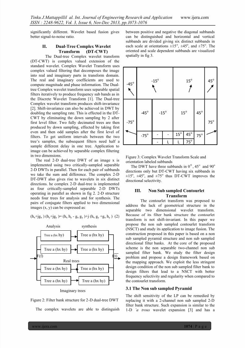
The complex wavelets are able to distinguish
between positive and negative the diagonal subbands
can be distinguished and horizontal and vertical
subbands are divided giving six distinct subbands in
each scale at orientations ±15o, ±45
o, and ±75
o. The
oriented and scale dependent subbands are visualized
spatially in fig 3.
-45o
-15o 15
o 45
o
-75o
-45o -15
o 15
o 45
o
75o
-75o -
-
15o 45
o 75
o
-
L L 75o
Figure 3: Complex Wavelet Transform Scale and
orientation labeled subbands
The DWT have three subbands in 00
, 45o
and 90o
directions only but DT-CWT having six subbands in
±15o, ±45
o, and ±75
o thus DT-CWT improves the
directional selectivity.
III. Non Sub sampled Contourlet
TransformThe contourlet transform was proposed to
address the lack of geometrical structure in the
separable two dimensional wavelet transform.
Because of its filter bank structure the contourlettransform is not shift-invariant. In this paper we
propose the non sub sampled contourlet transform
(NSCT) and study its application to image fusion. The
construction proposed in this paper is based on a non
sub sampled pyramid structure and non sub sampled
directional filter banks. At the core of the proposedscheme is the non separable two-channel non sub
sampled filter bank. We study the filter design
problem and propose a design framework based on
the mapping approach. We exploit the less stringent
design condition of the non sub sampled filter bank to
design filters that lead to a NSCT with better
frequency selectivity and regularity when compared to
the contourlet transform.
3.1 The Non sub sampled Pyramid
The shift sensitivity of the LP can be remedied by
replacing it with a 2-channel non sub sampled 2-D
filter bank structure. Such expansion is similar to the1-D `a trous wavelet expansion [3] and has a
Tree a (hx hy) Tree a (hx hy)
Tree a (hx hy) Tree a (hx hy)
Tree a (hx hy) Tree a (hx hy)
Tree a (hx hy) Tree a (hx hy)
8/13/2019 Fw 3610731076
http://slidepdf.com/reader/full/fw-3610731076 3/4
Tinku J.Mattappillil al. Int. Journal of Engineering Research and Application www.ijera.com ISSN : 2248-9622, Vol. 3, Issue 6, Nov-Dec 2013, pp.1073-1076
www.ijera.com 1075 | P a g e
redundancy of J + 1 when J is the number of
decomposition stages. The ideal frequency support of
the low-pass filter at the jth
stage is the region
. Accordingly, the support of
the high-pass filter is the complement of the low-pass
support region on the
square .The proposed structure is thus different from
the tensor product a trous algorithm. It has J + 1
redundancy. By contrast, the 2-D `a trous algorithm
has 3J + 1 redundancy.
Figure 4: Two types of desired responses (a) The pyramid desired response. (b) The fan desiredresponse.
The directional filter bank [3] is constructed by
combining critically sampled fan filter banks and
pre/post re-sampling operations. The result is a tree-
structured filter bank which splits the frequency plane
into directional wedges. A fully shift-invariantdirectional expansion is obtained by simply switching
off the down samplers and up samplers in the DFB
equivalent filter bank. Due to multi rate identities, this
is equivalent to switching off each of the down
samplers in the tree structure, while still keeping the
re-sampling operations that can be absorbed by thefilters. This results in a tree structure composed of
two-channel non sub sampled filter banks. The NSCT
is obtained by carefully combining the 2-D non sub
sampled pyramid and the non sub sampled DFB
(NSDFB) [4].The resulting filtering structureapproximates the ideal partition of the frequency
plane displayed in fig 1. It must be noted that,
different from the contourlet expansion, the NSCT has
a redundancy given as:
(3)
where 2lj is the number of directions at scale j.
IV. Fusion of ImagesAbout wavelet Fusion of two registered
images already discussed in section 1.1. In wavelet
based image fusion first any one of wavelet applied to
the image, after that we used one of the fusion rule for
fusing the wavelet coefficients. After that, apply the
inverse wavelet to reconstruct the image. In this, For
fusion uses any one of the fusion rule mention bellow.
There are three fusion rules generally used to
implement wavelet based image fusion.
1. Maximum Selection (MS) scheme: This simplescheme just picks the coefficient in each subband with
the largest magnitude2. Weighted Average (WA) scheme: This scheme
developed by Burt and Kolczynski [Burt and
Kolczynski, 1993] uses a normalized correlation
between the two images’ subbands over a small local
area. The resultant coefficient for reconstruction is
calculated from this measure via a weighted average
of the two images coefficients.
3. Window Based Verification Scheme: This scheme
developed by Li et al [Li et al, 1995] Creates a binarydecision map to choose between each pair of
coefficients using a majority filter.
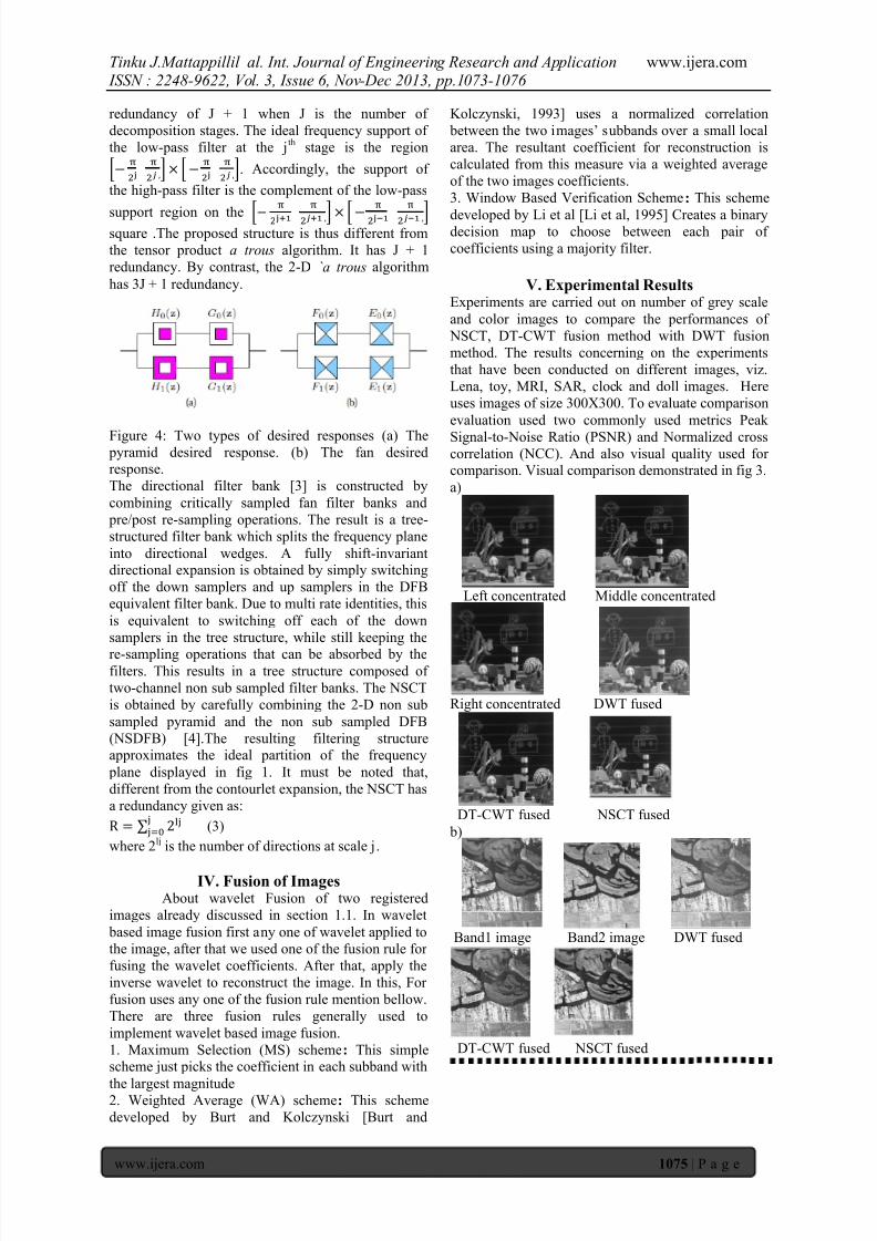
V. Experimental ResultsExperiments are carried out on number of grey scale
and color images to compare the performances of
NSCT, DT-CWT fusion method with DWT fusion
method. The results concerning on the experiments
that have been conducted on different images, viz.
Lena, toy, MRI, SAR, clock and doll images. Here
uses images of size 300X300. To evaluate comparison
evaluation used two commonly used metrics Peak
Signal-to-Noise Ratio (PSNR) and Normalized crosscorrelation (NCC). And also visual quality used forcomparison. Visual comparison demonstrated in fig 3.
a)
Left concentrated Middle concentrated
Right concentrated DWT fused
DT-CWT fused NSCT fused
b)
Band1 image Band2 image DWT fused
DT-CWT fused NSCT fused
8/13/2019 Fw 3610731076
http://slidepdf.com/reader/full/fw-3610731076 4/4
Tinku J.Mattappillil al. Int. Journal of Engineering Research and Application www.ijera.com ISSN : 2248-9622, Vol. 3, Issue 6, Nov-Dec 2013, pp.1073-1076
www.ijera.com 1076 | P a g e
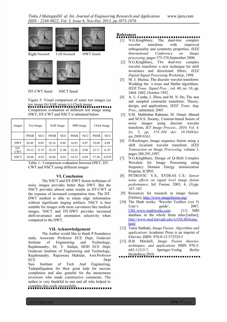
Right focused Left focused DWT fused
DT-CWT fused NSCT fused
Figure 5: Visual comparison of some test images (a)
toy image (b) SAR image (c) Clock image
Comparison evaluation of different test image using
DWT, DT-CWT and NSCT is tabulated below.
Table 1: Comparison evaluation between DWT, DT-
CWT and NSCT using different images
VI. ConclusionThe NSCT and DT-DWT fusion technique of
noisy images provides better than DWT .But the NSCT provides almost same results as DT-CWT at
the expense of increased computation time. The DT-
DWT method is able to retain edge information
without significant ringing artifacts. NSCT is best
suitable for images with more curvatures like medical
images. NSCT and DT-DWT provides increasedshift-invariance and orientation selectivity when
compared to the DWT.
VII. AcknowledgementThe Author would like to thank P.Soundarya
mala, Associate Professor ECE Dept, Godavari
Institute of Engineering and Technology,
Rajahmundry, Dr. V. Sailaja, HOD ECE Dept,
Godavari Institute of Engineering and Technology,Rajahmundry, Rajeswara Mahidar, Asst.Professor
ECE Dept
Sasi Institute of Tech And Engineering,
Tadepalligudem for their great help for success
completion and also grateful for the anonymous
reviewers who made constructive comments. The
author is very thankful to one and all who helped tocomplete this work successfully.
References
[1] N.G.Kingbbury, The dual-tree complex
wavelet transform with improvedorthogonality and symmetry properties, IEEE
International Conference on Image
processing , pages 375-378,September 2000. [2] N.G.Kingbbury, The dual-tree complex
wavelet transform: a new technique for shift
invariance and directional filters, IEEE
Digital Signal Processing Workshop, 1998.
[3] M. J. Shensa, The discrete wavelet transform:
Wedding the `a trous and Mallat algorithms.
IEEE Trans. Signal Proc. , vol. 40, no. 10, pp.
2464 – 2482, October 1992.
[4] A. L. Cunha, J. Zhou, and M. N. Do, The nonsub sampled contourlet transform: Theory,
design, and applications, IEEE Trans. Img.
Proc., submitted, 2005.
[5] S.M. Mahbubur Rahman, M. Omair Ahmad
and M.N.S. Swamy, Contrast-based fusion ofnoisy images using discrete wavelet
transform, IET Image Process., 2010, Vol. 4,
Iss. 5, pp. 374 – 384 doi: 10.1049/iet-
ipr.2009.0163.
[6] O.Rockinger, Image sequence fusion using a
shift invariant wavelet transform IEEETransaction on Image Processing, volume 3,
pages 288-291,1997.
[7] N.G.Kingbbury, Design of Q-Shift Complex
Wavelets for Image Processing using
frequency Domain Energy minimization
Preprint, ICIP03.
[8] PETROVIC´ V.S., XYDEAS C.S.: Sensor
noise effects on signal level image fusion
performance, Inf. Fusion, 2003, 4, (3),pp.
167 – 183
[9] Resources for research in image fusion:
[Online], http://www.imagefusion.org/
[10] The Math works, ‘Wavelet Toolbox (ver 5)
User’s guide’, 2007,
URL:www.mathworks.com. [11] MRI
database in the whole brain atlas:[online],
http://www.med.harvadr.edu/AANLIB/home.html
[12] Tania Stathaki, Image Fusion Algorithms and
applications Academic Press is an imprint of
Elsevier, ISBN: 978-0-12-372529-5
[13] H.B. Mitchell, Image Fusion theories,
techniques, and applications ISBN 978-3-
642-11215-7, Springer-Verlag Berlin
Heidelberg,2010.
images Toy Image SAR Image MRI image Clock Image
PSNR NCC PSNR NCC PSNR NCC PSNR NCC
DWT 20.49 0.89 18.14 0.88 16.83 0.87 19.89 0.89
DT-
CWT34.13 0. 97 32.19 0. 98 32.36 0.98 33.71 0..97
NSCT 34.98 0.93 34.96 0.92 34.52 0.99 37.50 0.879