
Evaluatie fotovoltaïsch-thermische zonnepanelen (PVT) fotovoltaisch... · Evaluatie...
70
Evaluatie fotovoltaïsch-thermische zonnepanelen (PVT) EOS-LT Waels Datum Augustus 2008 ECN, H.A. Zondag In opdracht van SenterNovem (nu Rijksdienst voor Ondernemend Nederland) Publicatienr RVO-156-1501/RP-DUZA www.rvo.nl Dit rapport is tot stand gekomen in opdracht van het ministerie van Economische Zaken.
Transcript of Evaluatie fotovoltaïsch-thermische zonnepanelen (PVT) fotovoltaisch... · Evaluatie...

Evaluatie fotovoltaïsch-thermische zonnepanelen (PVT)
EOS-LT Waels
Datum
Augustus 2008
ECN, H.A. Zondag
In opdracht van SenterNovem (nu Rijksdienst voor
Ondernemend Nederland)
Publicatienr
RVO-156-1501/RP-DUZA
www.rvo.nl
Dit rapport is tot stand gekomen in opdracht van het ministerie van
Economische Zaken.

Realized PV/T installations - experiences
and monitoring results
Report DD2/DD3 of IEA SHC Task 35 on PV/Thermal Solar
Systems
August 2008
FINAL DRAFT
Report compiled by:
H.A. Zondag,
Energy research Centre of
The Netherlands (ECN)
Final draft version, May 2007
2
Report DD2/DD3 of subtask D
Realized PV/T installations - experiences and
monitoring results
By
Herbert Zondag
Energy research Centre of the Netherlands (ECN)
This report can be downloaded at the IEA SHC task 35 website: www.pv-t.org

Final draft version, May 2007
3
IEA Solar Heating and Cooling Programme
The International Energy Agency (IEA) is an autonomous body within the framework of the
Organization for Economic Co-operation and Development (OECD) based in Paris. Established in
1974 after the first “oil shock,” the IEA is committed to carrying out a comprehensive program of
energy cooperation among its members and the Commission of the European Communities.
The IEA provides a legal framework, through IEA Implementing Agreements such as the Solar
Heating and Cooling Agreement, for international collaboration in energy technology research and
development (R&D) and deployment. This IEA experience has proved that such collaboration
contributes significantly to faster technological progress, while reducing costs; to eliminating
technological risks and duplication of efforts; and to creating numerous other benefits, such as swifter
expansion of the knowledge base and easier harmonization of standards.
The Solar Heating and Cooling Programme was one of the first IEA Implementing Agreements to be
established. Since 1977, its members have been collaborating to advance active solar and passive solar
and their application in buildings and other areas, such as agriculture and industry. Current members
are:
Australia Finland Portugal
Austria France Spain
Belgium Italy Sweden
Canada Mexico Switzerland
Denmark Netherlands United States
European Commission New Zealand
Germany Norway
A total of 39 Tasks have been initiated, 30 of which have been completed. Each Task is managed by
an Operating Agent from one of the participating countries. Overall control of the program rests with
an Executive Committee comprised of one representative from each contracting party to the
Implementing Agreement. In addition to the Task work, a number of special activities—Memorandum
of Understanding with solar thermal trade organizations, statistics collection and analysis, conferences
and workshops—have been undertaken.
Final draft version, May 2007
4
The Tasks of the IEA Solar Heating and Cooling Programme, both underway and completed are as
follows:
Current Tasks:
Task 32 Advanced Storage Concepts for Solar and Low Energy Buildings
Task 33 Solar Heat for Industrial Processes
Task 34 Testing and Validation of Building Energy Simulation Tools
Task 35 PV/Thermal Solar Systems
Task 36 Solar Resource Knowledge Management
Task 37 Advanced Housing Renovation with Solar & Conservation
Task 38 Solar Assisted Cooling Systems
Task 39 Polymeric Materials for Solar Thermal Applications
Completed Tasks:
Task 1 Investigation of the Performance of Solar Heating and Cooling Systems
Task 2 Coordination of Solar Heating and Cooling R&D
Task 3 Performance Testing of Solar Collectors
Task 4 Development of an Insolation Handbook and Instrument Package
Task 5 Use of Existing Meteorological Information for Solar Energy Application
Task 6 Performance of Solar Systems Using Evacuated Collectors
Task 7 Central Solar Heating Plants with Seasonal Storage
Task 8 Passive and Hybrid Solar Low Energy Buildings
Task 9 Solar Radiation and Pyranometry Studies
Task 10 Solar Materials R&D
Task 11 Passive and Hybrid Solar Commercial Buildings
Task 12 Building Energy Analysis and Design Tools for Solar Applications
Task 13 Advance Solar Low Energy Buildings
Task 14 Advance Active Solar Energy Systems
Task 16 Photovoltaics in Buildings
Task 17 Measuring and Modeling Spectral Radiation
Task 18 Advanced Glazing and Associated Materials for Solar and Building Applications
Task 19 Solar Air Systems
Task 20 Solar Energy in Building Renovation
Task 21 Daylight in Buildings
Task 23 Optimization of Solar Energy Use in Large Buildings
Task 22 Building Energy Analysis Tools
Task 24 Solar Procurement
Task 25 Solar Assisted Air Conditioning of Buildings
Task 26 Solar Combisystems
Task 28 Solar Sustainable Housing
Task 27 Performance of Solar Facade Components
Task 29 Solar Crop Drying
Task 31 Daylighting Buildings in the 21st Century
Completed Working Groups:
CSHPSS, ISOLDE, Materials in Solar Thermal Collectors, and the Evaluation of Task 13
Houses
To find Solar Heating and Cooling Programme publications and learn more about the Programme visit
www.iea-shc.org or contact the SHC Executive Secretary, Pamela Murphy, e-mail:
September 2007

Final draft version, May 2007
5
Executive Summary
At this moment, worldwide only a very small number of commercial PV/T products
exists and the amount of realized projects with these collectors is small. This is in
marked contrast to the large potential that is seen for such systems as a standard solar
component in both renovation and new housing projects, in particular if the available
area is limited, such as for multifamily buildings. The International Energy Agency
(IEA) Solar Heating and Cooling (SHC) Programme, Task 35 on PV/Thermal Solar
Systems was set up to improve this situation by generating awareness for PV/Thermal
Solar Systems and catalysing the further development and marketing of PV/T
systems.
In order to show the potential of PV/T systems and to help disseminating the lessons
learnt, the present overview report on realised PV/T installations was compiled. All
together, the report presents information on 70 realised PV/T installations. Most of
these systems are PV/T-air systems (39 systems), but also 15 PV/T-liquid systems are
described, as well as 16 systems with PVT collectors heating both liquid and air. Most
of the PV/T-air projects have been built by the German manufacturer Grammer Solar
using their unglazed PV-air collector. Another large number of projects was realized
in national Danish projects led by the Danish consultant Cenergia, applying ventilated
PV facades with heat recovery, as well as Solarwall systems. The oldest residential
PV/T air installation found in the project was realized in the USA by Sunwatt in 1987;
it is still in operation.
With respect to liquid collectors, a number of systems was realised recently in
Thailand, in which 5 large-scale PV/T systems were installed on various
governmental buildings over a period of about 2 years (2003-2004). These systems
have been developed by NSTDA and are mostly unglazed PV/T collectors using
amorphous silicon, but in one project also glazed PV/T collectors were used. The
largest of these systems is a 152 m2 system on the Queen Sirikit hospital in Chonburi.
Other projects to be mentioned are a 54 m2 glazed PV/T liquid project that was
realised by the Dutch companies ECN, Shell Solar and ZEN Solar in the UK in 2003.
This PV/T work has been continued by the ECN spin off company PVTWINS, that in
2007 has realized a 27 m2 glazed PV/T liquid system on a Dutch governmental
building and five 2.8 m2 systems in a residential renovation project, while more
market introduction projects have been planned for 2008.
With respect to the PVT systems heating both liquid and air, a large number of
systems was realized by the company Solor, that has realized projects with unglazed
PV/T collectors from 1991 onwards, among which several PV/T systems installed at 6
off-grid residences in Klil village, 2 PV/T systems in a recreation village in the Negev
desert and 2 PV/T systems on an alpaca farm. Since 1999, the PV/T activities of Solor
have been taken over by Millennium Electric, that is now marketing these systems.
Concluding, it can be stated that PV/T is an interesting technique with a large
potential and a large amount of experience on PV/T is available. After a long market
preparation phase in PV/T development, we hope that the results obtained in this task
will contribute to the final take-off of the PV/T market.
Finally, while some demonstration projects run smoothly, others may be plagued by
various unforeseen problems. From the reports on the various demonstration projects,
a number of lessons has been learnt:
Realize beforehand that the PV/T project is in many cases additional to an
existing building project or renovation project, that has its own dynamics;
Final draft version, May 2007
6
substantial delays may occur during this process and it is wise to allow for
these in the planning of the deadline of the PV/T project. Also, substantial
delays in the PV/T project compromising the commissioning date of the
building can often not be tolerated.
It is an important asset if the architect, building owner, local authorities and
other parties in the building process are convinced from the start of the
importance of the PV/T system to the project, are motivated to apply and it
have sufficient knowledge about it.
Safety issues, roof mounting and roof integration issues, responsibility issues
and warranties may take a substantial amount of time in the project.
Limit the amount of new components in the project, since the larger the
amount of components to be developed within the project, the larger the
chance that delays may occur. If the central item in the demonstration is the
PV/T, then try to use standard components for the other aspects as much as
possible. In addition, be aware that the production of a large number of non-
standard components (including possibly the PV/T modules itself) may be
costly and not easy to realize.
Monitoring is crucial to detect errors in the installation, which are often caused
by malfunctioning components (sensors, bypasses, etc). This is particularly
relevant if these errors substantially reduce the energy saving function of the
system, e.g. by requiring too much electrical power for pumps and fans, or
compromising the control of the system due to malfunctioning sensors, valves
or bypasses. Allow sufficient time and money for monitoring and be aware
that in this phase also time should be available to change malfunctioning
components and malfunctioning monitoring sensors, and it should be clear
whose responsibility it is to make these changes. In addition, it is highly
recommended to set up an automated monitoring environment that can be read
through a (publicly accessible) website.
Dissemination is very important and can be realized by various means, ranging
from allowing group visits to websites and publications in magazines or
conference proceedings.
Final draft version, May 2007
7
1 Introduction ............................................................................................................ 8
2 PV/T air projects .................................................................................................. 13
2.1 Glazed PV/T air collectors ........................................................................... 13
2.1.1 Aidt Miljø (Denmark) .......................................................................... 13
2.2 Unglazed PV/T air collectors ....................................................................... 14
2.2.1 OKA Haus der Zukunft (Austria) ........................................................ 14
2.2.2 Solarwall (Canada)............................................................................... 15
2.2.3 Grammer Solar (Germany) .................................................................. 17
2.3 Building integrated PV with heat recovery .................................................. 20
2.3.1 Atlantis Energy (Switzerland).............................................................. 20
2.3.2 ETH (Switzerland) ............................................................................... 22
2.3.3 NTNU building (Norway).................................................................... 23
2.3.4 Doxford solar office building (UK) ..................................................... 24
2.3.5 MANCAT building (UK) .................................................................... 25
2.3.6 Secco Sistemi (Italy) ............................................................................ 26
2.3.7 Cenergia (Denmark)............................................................................. 28
2.3.8 Arkitema (Denmark) ............................................................................ 34
2.3.9 Esbensen (Denmark) ............................................................................ 35
2.3.10 TFM (Spain)......................................................................................... 36
2.3.11 Innovative design & NCSC (USA) ...................................................... 38
2.4 Concentrating PV/T air collectors ............................................................... 40
2.4.1 SunWatt Corp. (USA) .......................................................................... 40
3 PV/T liquid projects ............................................................................................. 41
3.1 Glazed PV/T liquid projects......................................................................... 41
3.1.1 Beaufort Court building (UK) .............................................................. 41
3.1.2 PVTWINS ............................................................................................ 43
3.1.3 NSTDA (Thailand) .............................................................................. 44
3.1.4 Hong Kong City University ................................................................. 45
3.2 Unglazed PV/T liquid projects..................................................................... 46
3.2.1 NSTDA (Thailand) .............................................................................. 46
3.2.2 PVTWINS ............................................................................................ 47
3.3 Concentrating PV/T liquid collectors .......................................................... 48
3.3.1 SunWatt Corp. (USA) .......................................................................... 48
3.3.2 Arontis (Sweden) ................................................................................. 50
3.3.3 Bruce Hall building (Australia) ........................................................... 51
4 PV/T combined air&liquid projects ..................................................................... 53
4.1 Millennium Electric & Solor (Israel) ........................................................... 53
5 PV/T project experiences – lessons learnt ........................................................... 57
6 Conclusions .......................................................................................................... 63
7 References ............................................................................................................ 66
Final draft version, May 2007
8
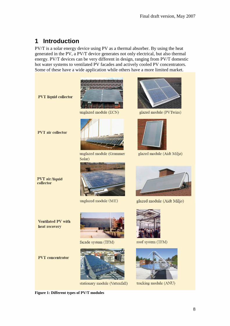
1 Introduction PV/T is a solar energy device using PV as a thermal absorber. By using the heat
generated in the PV, a PV/T device generates not only electrical, but also thermal
energy. PV/T devices can be very different in design, ranging from PV/T domestic
hot water systems to ventilated PV facades and actively cooled PV concentrators.
Some of these have a wide application while others have a more limited market.
Figure 1: Different types of PV/T modules
Final draft version, May 2007
9
Over the last 20 years a number of PV/T demonstration projects has been realised in
various countries. Among the earlier systems were the PV/T systems heating both
liquid and air, that have been installed by the company Solor since 1991 (later
continued by Millennium Electric) and the PV/T air systems that were installed by
Atlantis Energy since 1993. Among the most recent projects are a large series of PV/T
liquid systems in Thailand and a PV/T concentrator installation realised by the
Swedish company Arontis. The aim of this present report is to give an overview of all
realized PV/T installations in market introduction projects and demonstration projects.
Unfortunately, the available information on most projects is limited; not all projects
have been monitored and on some only very limited information is available, while
large monitoring reports have been published on others.
The information presented here was collected from manufacturers that are known to
be active in this field, complemented with systems that were described in conference
papers, scientific papers and EU reports, or that were found though a search on the
internet. Although it is expected that the overview assembled in this way will not be
complete, it is also expected that the majority of the PV/T systems realized worldwide
over the last 20 years is identified and described in this report.
Altogether, 70 different systems were found; 39 systems with PVT air collectors, 15
systems with PVT liquid collectors and 16 systems with combined PVT collectors
heating both liquid and air.
A huge amount of PVT-air installations exists in the form of small
autonomous PVT installations for summer cottages, sold by Grammer Solar
and Aidt Miljø / Solarventi1. On the website of Aidt Miljø, it is indicated that
over 11.000 (!) Solarventi modules had been sold in Denmark from the market
introduction up to January 2006. Although an example of both products is
given in the report, it was clearly impossible to present all these installations.
Most PVT air systems in this report were realized by Grammer Solar (10), all
but one realized in Germany. Furthermore, 4 systems were realized by
Solarwall in the USA and Canada, and 6 by Cenergia in Denmark (in some of
the Cenergia projects also Solarwall collectors were used). Also Atlantis
Energy should be mentioned, that realised 4 PVT shingle roofs in the 1990’s.
Furthermore, the Italian company Secco Sistemi has developed, together with
the Polytechnical University of Milano, a standardized PVT roof element, that
was applied in two projects, while the Spanish company TFM also constructed
two ventilated PV systems.
Most PVT liquid systems were realized by Sunwatt; in the report only 3
installations by Sunwatt are mentioned, but in addition, in the 1980’s Sunwatt
produced two commercial types of PVT concentrators, the H100 and H150,
and states that over 100 of these devices had been made and installed during
the period of 1981 to 1989 when the H100 and H150 were produced
commercially. Recently, 4 large PVT systems have been developed and
installed in demonstration projects by NSTDA in Thailand, while the Dutch
company PVTWINS has realized 3 PVT projects in the Netherlands.
A large number of PVT collectors heating both air and liquid simultaneously
has been manufactured and installed by Millennium Electric. In the report, 16
systems are described, all off-grid. Most of these collectors have been installed
1 The original company name Aidt Miljø was changed to Solarventi in 2006.

Final draft version, May 2007
10
in Israel, but also 3 abroad. Recently, also the Danish company Solarventi
introduced a PVT module that can heat both air and water; the SV30 hybrid.
Of all the systems mentioned, only 6 systems are concentrating PVT
installations, 5 of which are stationary concentrators produced by Sunwatt and
Arontis, and only 1 is a tracking system, realized by the Australian National
University. Other manufacturers of concentrating PVT systems are
Heliodynamics and Menova Engineering, but no information could be
obtained on their installations.
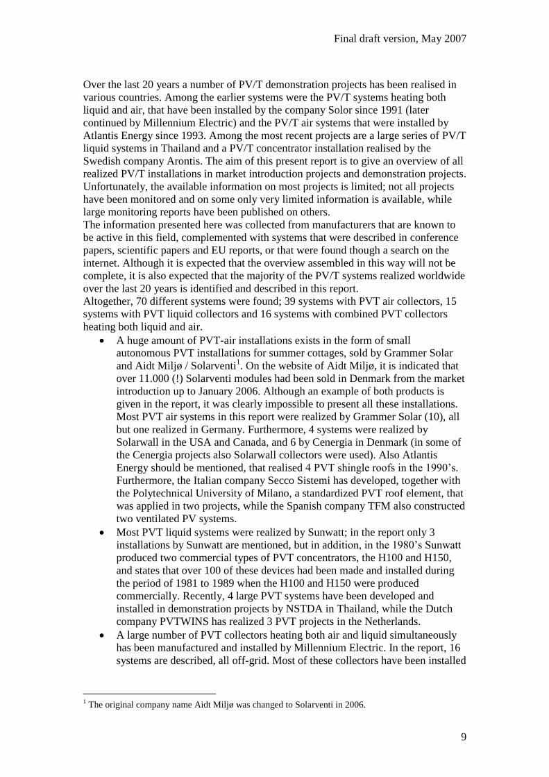
The information on the systems is summarized in Figure 1 and Figure 2.
Final draft version, May 2007
11
Figure 2: PV/T air projects
Final draft version, May 2007
12
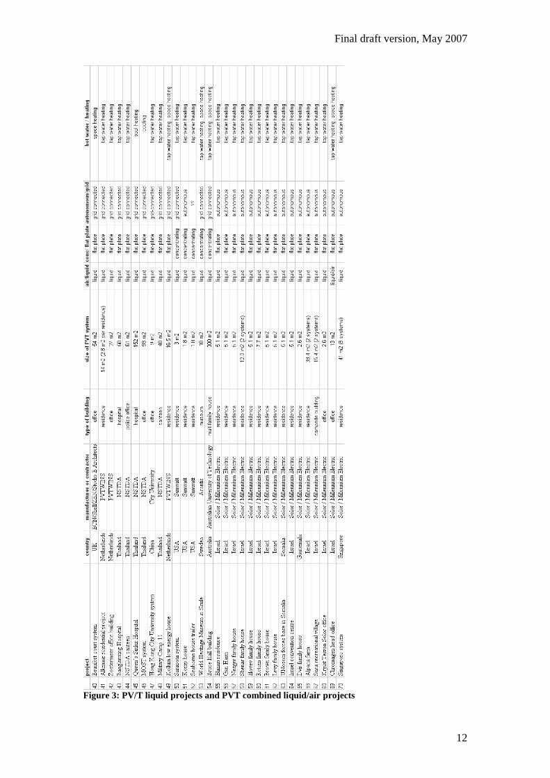
Figure 3: PV/T liquid projects and PVT combined liquid/air projects
Final draft version, May 2007
13
2 PV/T air projects
2.1 Glazed PV/T air collectors
2.1.1 Aidt Miljø (Denmark)
Mass-produced do-it-yourself PV/T packages for summer houses are provided by
Grammer (unglazed PV) and Aidt Miljø (glazed PV). The main purpose of these
systems is to prevent moisture problems during the winter; during the presence of the
owner in the summer, the system may be switched off to prevent overheating. The PV
output is used to drive the collector fan, providing heated ventilation air to the cottage.
As a typical case, Robert Hastings (1999) gives a description of a system of Aidt
Miljø in a Summer House at Slettestrand, Denmark.
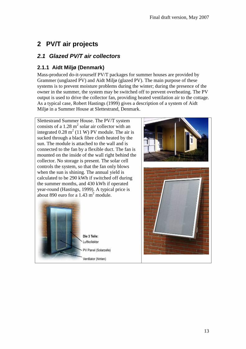
Slettestrand Summer House. The PV/T system
consists of a 1.28 m2 solar air collector with an
integrated 0.28 m2 (11 W) PV module. The air is
sucked through a black fibre cloth heated by the
sun. The module is attached to the wall and is
connected to the fan by a flexible duct. The fan is
mounted on the inside of the wall right behind the
collector. No storage is present. The solar cell
controls the system, so that the fan only blows
when the sun is shining. The annual yield is
calculated to be 290 kWh if switched off during
the summer months, and 430 kWh if operated
year-round (Hastings, 1999). A typical price is
about 890 euro for a 1.43 m2 module.
Final draft version, May 2007
14
2.2 Unglazed PV/T air collectors
2.2.1 OKA Haus der Zukunft (Austria)
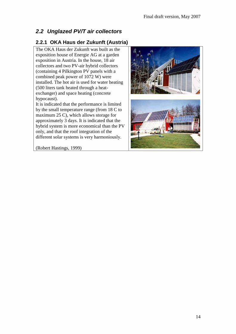
The OKA Haus der Zukunft was built as the
exposition house of Energie AG at a garden
exposition in Austria. In the house, 18 air
collectors and two PV-air hybrid collectors
(containing 4 Pilkington PV panels with a
combined peak power of 1072 W) were
installed. The hot air is used for water heating
(500 liters tank heated through a heat-
exchanger) and space heating (concrete
hypocaust).
It is indicated that the performance is limited
by the small temperature range (from 18 C to
maximum 25 C), which allows storage for
approximately 3 days. It is indicated that the
hybrid system is more economical than the PV
only, and that the roof integration of the
different solar systems is very harmoniously.
(Robert Hastings, 1999)
Final draft version, May 2007
15
2.2.2 Solarwall (Canada)
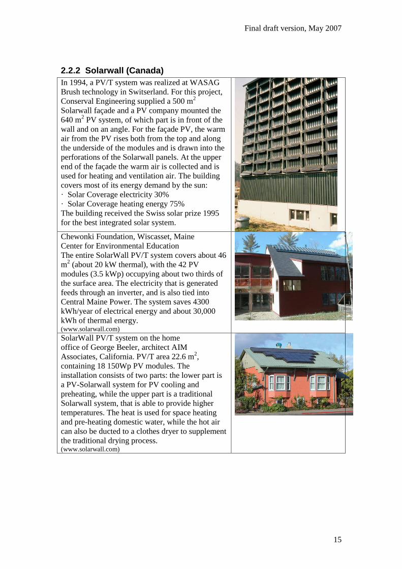
In 1994, a PV/T system was realized at WASAG
Brush technology in Switserland. For this project,
Conserval Engineering supplied a 500 m2
Solarwall façade and a PV company mounted the
640 m2 PV system, of which part is in front of the
wall and on an angle. For the façade PV, the warm
air from the PV rises both from the top and along
the underside of the modules and is drawn into the
perforations of the Solarwall panels. At the upper
end of the façade the warm air is collected and is
used for heating and ventilation air. The building
covers most of its energy demand by the sun:
· Solar Coverage electricity 30%
· Solar Coverage heating energy 75%
The building received the Swiss solar prize 1995
for the best integrated solar system.
Chewonki Foundation, Wiscasset, Maine
Center for Environmental Education
The entire SolarWall PV/T system covers about 46
m2 (about 20 kW thermal), with the 42 PV
modules (3.5 kWp) occupying about two thirds of
the surface area. The electricity that is generated
feeds through an inverter, and is also tied into
Central Maine Power. The system saves 4300
kWh/year of electrical energy and about 30,000
kWh of thermal energy. (www.solarwall.com)
SolarWall PV/T system on the home
office of George Beeler, architect AIM
Associates, California. PV/T area 22.6 m2,
containing 18 150Wp PV modules. The
installation consists of two parts: the lower part is
a PV-Solarwall system for PV cooling and
preheating, while the upper part is a traditional
Solarwall system, that is able to provide higher
temperatures. The heat is used for space heating
and pre-heating domestic water, while the hot air
can also be ducted to a clothes dryer to supplement
the traditional drying process. (www.solarwall.com)

Final draft version, May 2007
16
Some portable classrooms in Southern Ontario
experienced poor air quality and mold growth. To
correct this problem, a 15 m² SOLARWALL was
installed with two 60 W a-Si panels that power two
variable-speed 340 m³/hr fans bringing solar
heated fresh air into the classroom. The air, heated
as much as 30°C above ambient, is then distributed
in the classroom by two – 150 mm diameter ducts. (www.solarwall.com)
Final draft version, May 2007
17
2.2.3 Grammer Solar (Germany)
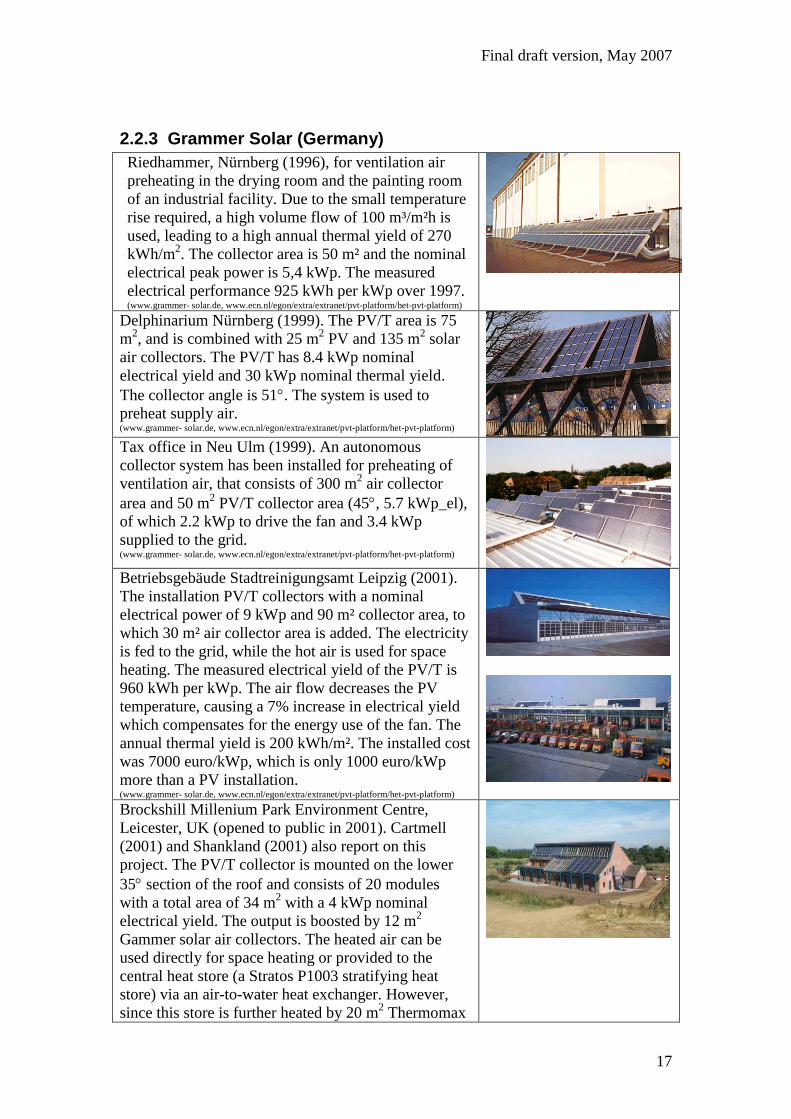
Riedhammer, Nürnberg (1996), for ventilation air
preheating in the drying room and the painting room
of an industrial facility. Due to the small temperature
rise required, a high volume flow of 100 m³/m²h is
used, leading to a high annual thermal yield of 270
kWh/m2. The collector area is 50 m² and the nominal
electrical peak power is 5,4 kWp. The measured
electrical performance 925 kWh per kWp over 1997. (www.grammer- solar.de, www.ecn.nl/egon/extra/extranet/pvt-platform/het-pvt-platform)
Delphinarium Nürnberg (1999). The PV/T area is 75
m2, and is combined with 25 m
2 PV and 135 m
2 solar
air collectors. The PV/T has 8.4 kWp nominal
electrical yield and 30 kWp nominal thermal yield.
The collector angle is 51. The system is used to
preheat supply air. (www.grammer- solar.de, www.ecn.nl/egon/extra/extranet/pvt-platform/het-pvt-platform) Tax office in Neu Ulm (1999). An autonomous
collector system has been installed for preheating of
ventilation air, that consists of 300 m2 air collector
area and 50 m2 PV/T collector area (45, 5.7 kWp_el),
of which 2.2 kWp to drive the fan and 3.4 kWp
supplied to the grid. (www.grammer- solar.de, www.ecn.nl/egon/extra/extranet/pvt-platform/het-pvt-platform)
Betriebsgebäude Stadtreinigungsamt Leipzig (2001).
The installation PV/T collectors with a nominal
electrical power of 9 kWp and 90 m² collector area, to
which 30 m² air collector area is added. The electricity
is fed to the grid, while the hot air is used for space
heating. The measured electrical yield of the PV/T is
960 kWh per kWp. The air flow decreases the PV
temperature, causing a 7% increase in electrical yield
which compensates for the energy use of the fan. The
annual thermal yield is 200 kWh/m². The installed cost
was 7000 euro/kWp, which is only 1000 euro/kWp
more than a PV installation. (www.grammer- solar.de, www.ecn.nl/egon/extra/extranet/pvt-platform/het-pvt-platform)
Brockshill Millenium Park Environment Centre,
Leicester, UK (opened to public in 2001). Cartmell
(2001) and Shankland (2001) also report on this
project. The PV/T collector is mounted on the lower
35 section of the roof and consists of 20 modules
with a total area of 34 m2 with a 4 kWp nominal
electrical yield. The output is boosted by 12 m2
Gammer solar air collectors. The heated air can be
used directly for space heating or provided to the
central heat store (a Stratos P1003 stratifying heat
store) via an air-to-water heat exchanger. However,
since this store is further heated by 20 m2 Thermomax

Final draft version, May 2007
18
evacuated tube collectors, during summer most of the
PV heat will not be needed for water heating and will
be vented to the ambient.
Unfortunately, some of the PV modules were
vandalized soon after installation so no data is
available for electrical output. The calculated payback
time was about 19 years.
(www.grammer- solar.de, www.ecn.nl/egon/extra/extranet/pvt-platform/het-pvt-platform/)
Recreational building Pliezhausen (2001), space
heating and tap water heating for a sports facility with
swimming pool. The PV/T area is 86 m2, resulting in
4.5 kWp nominal electrical yield. The collector angle
is 45. (www.grammer- solar.de, www.ecn.nl/egon/extra/extranet/pvt-platform/het-pvt-platform/) Umweltzentrum DarßerArche in national park near
Wieck (2001), water heating. The PV/T area is 23 m2,
resulting in 2.5 kWp nominal electrical yield and 8.5
kWp nominal thermal yield. The collector angle is
80. (www.grammer- solar.de, www.ecn.nl/egon/extra/extranet/pvt-platform/het-pvt-platform/) Fachhochschule Pirmasens (2002), preheating of
ventilation air for the atrium. The PV/T area is 14 m2,
resulting in 1.5 kWp nominal electrical yield. (www.grammer- solar.de, www.ecn.nl/egon/extra/extranet/pvt-platform/het-pvt-platform/)
Final draft version, May 2007
19
Depot of the fire brigade in Neustadt-Vogtland,
Germany (2007). The system consists of a 62 m2 PV/T
system (8.3 kWp_el, 25 kWp_th) in combination with
a conventional PV system (also 8.3 kWp_el). The
system provides preheating of fresh air and/or
recirculating air for space heating, dehumidification
and drying of wet equipment (e.g. clothes and fire
hoses), in combination with a heat recovery system
and an electric emergency heating system. The depot
function of the building allows a large variation of the
indoor temperature. (www.grammer- solar.de)
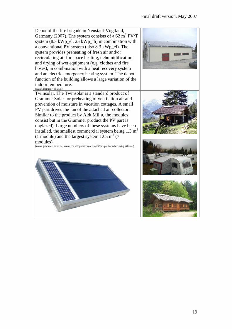
Twinsolar. The Twinsolar is a standard product of
Grammer Solar for preheating of ventilation air and
prevention of moisture in vacation cottages. A small
PV part drives the fan of the attached air collector.
Similar to the product by Aidt Miljø, the modules
consist but in the Grammer product the PV part is
unglazed). Large numbers of these systems have been
installed, the smallest commercial system being 1.3 m2
(1 module) and the largest system 12.5 m2 (7
modules). (www.grammer- solar.de, www.ecn.nl/egon/extra/extranet/pvt-platform/het-pvt-platform/)
Final draft version, May 2007
20
2.3 Building integrated PV with heat recovery
2.3.1 Atlantis Energy (Switzerland)
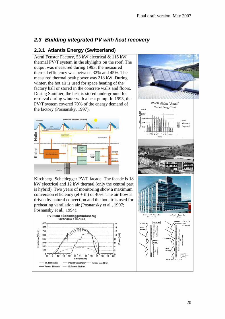
Aerni Fenster Factory, 53 kW electrical & 115 kW
thermal PV/T system in the skylights on the roof. The
output was measured during 1993; the measured
thermal efficiency was between 32% and 45%. The
measured thermal peak power was 218 kW. During
winter, the hot air is used for space heating of the
factory hall or stored in the concrete walls and floors.
During Summer, the heat is stored underground for
retrieval during winter with a heat pump. In 1993, the
PV/T system covered 70% of the energy demand of
the factory (Posnansky, 1997).
Kirchberg, Scheidegger PV/T-facade. The facade is 18
kW electrical and 12 kW thermal (only the central part
is hybrid). Two years of monitoring show a maximum
conversion efficiency (el + th) of 40%. The air flow is
driven by natural convection and the hot air is used for
preheating ventilation air (Posnansky et al., 1997;
Posnansky et al., 1994).
Final draft version, May 2007
21
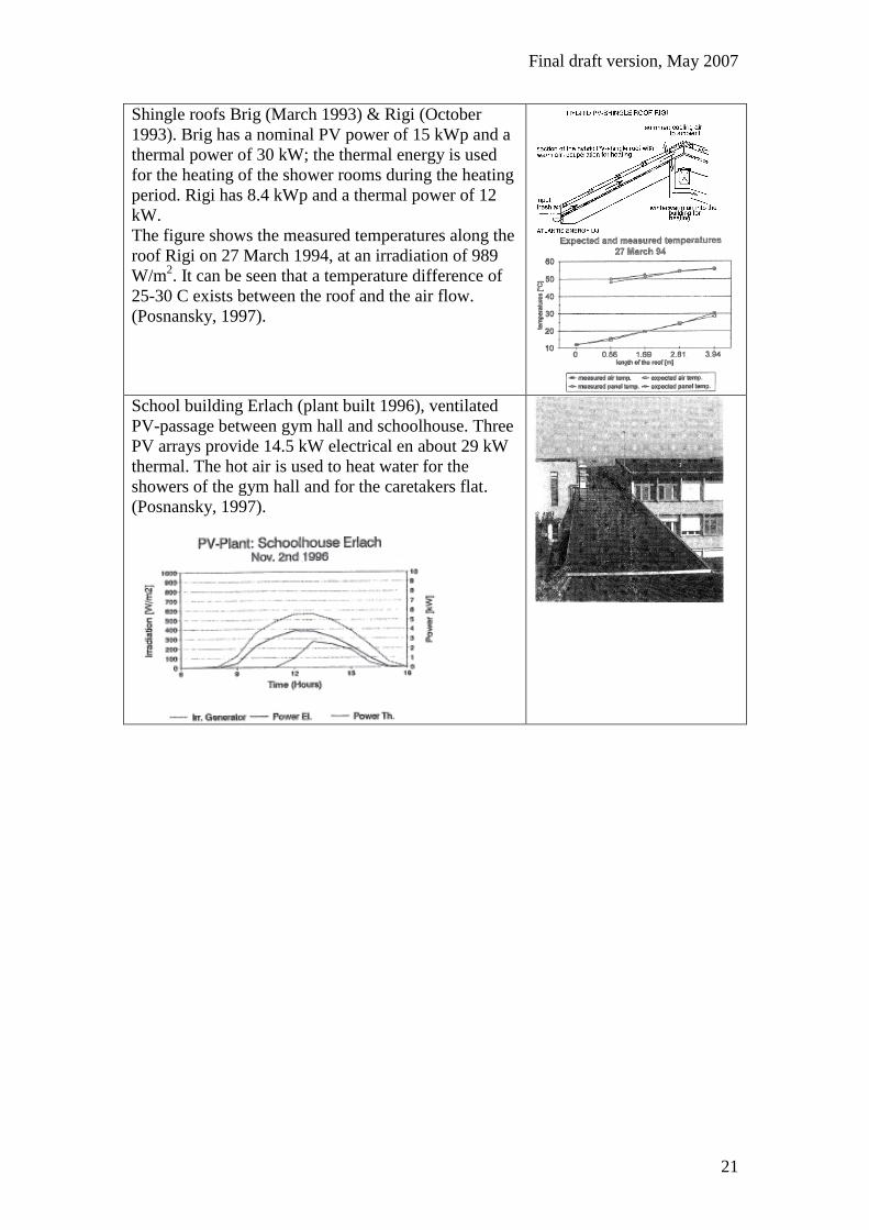
Shingle roofs Brig (March 1993) & Rigi (October
1993). Brig has a nominal PV power of 15 kWp and a
thermal power of 30 kW; the thermal energy is used
for the heating of the shower rooms during the heating
period. Rigi has 8.4 kWp and a thermal power of 12
kW.
The figure shows the measured temperatures along the
roof Rigi on 27 March 1994, at an irradiation of 989
W/m2. It can be seen that a temperature difference of
25-30 C exists between the roof and the air flow.
(Posnansky, 1997).
School building Erlach (plant built 1996), ventilated
PV-passage between gym hall and schoolhouse. Three
PV arrays provide 14.5 kW electrical en about 29 kW
thermal. The hot air is used to heat water for the
showers of the gym hall and for the caretakers flat.
(Posnansky, 1997).
Final draft version, May 2007
22
2.3.2 ETH2 (Switzerland)
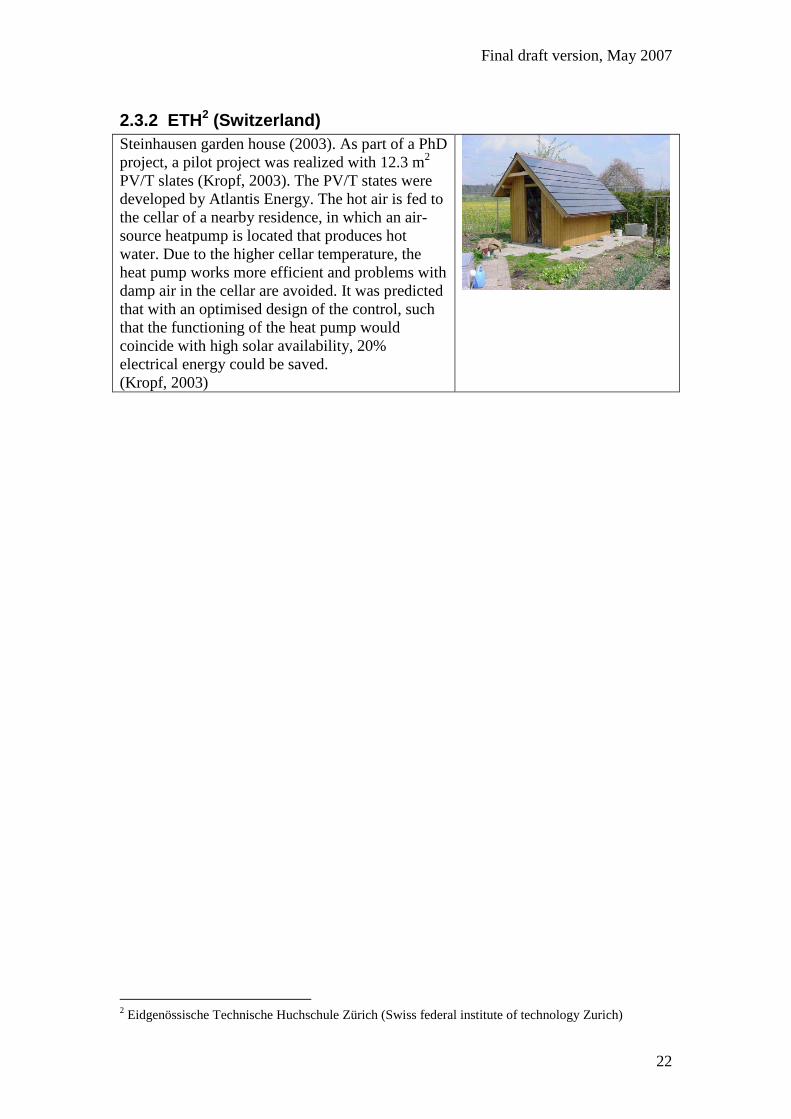
Steinhausen garden house (2003). As part of a PhD
project, a pilot project was realized with 12.3 m2
PV/T slates (Kropf, 2003). The PV/T states were
developed by Atlantis Energy. The hot air is fed to
the cellar of a nearby residence, in which an air-
source heatpump is located that produces hot
water. Due to the higher cellar temperature, the
heat pump works more efficient and problems with
damp air in the cellar are avoided. It was predicted
that with an optimised design of the control, such
that the functioning of the heat pump would
coincide with high solar availability, 20%
electrical energy could be saved.
(Kropf, 2003)
2 Eidgenössische Technische Huchschule Zürich (Swiss federal institute of technology Zurich)
Final draft version, May 2007
23
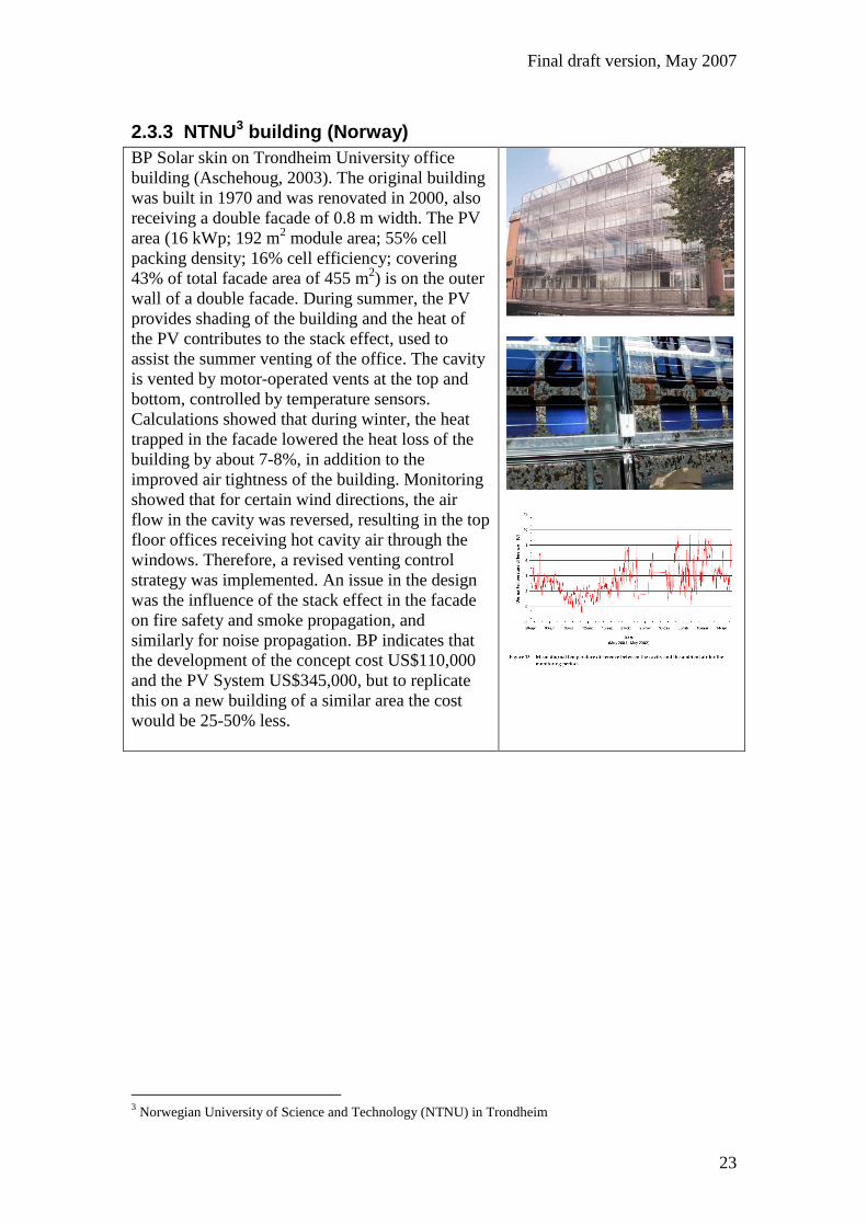
2.3.3 NTNU3 building (Norway)
BP Solar skin on Trondheim University office
building (Aschehoug, 2003). The original building
was built in 1970 and was renovated in 2000, also
receiving a double facade of 0.8 m width. The PV
area (16 kWp; 192 m2 module area; 55% cell
packing density; 16% cell efficiency; covering
43% of total facade area of 455 m2) is on the outer
wall of a double facade. During summer, the PV
provides shading of the building and the heat of
the PV contributes to the stack effect, used to
assist the summer venting of the office. The cavity
is vented by motor-operated vents at the top and
bottom, controlled by temperature sensors.
Calculations showed that during winter, the heat
trapped in the facade lowered the heat loss of the
building by about 7-8%, in addition to the
improved air tightness of the building. Monitoring
showed that for certain wind directions, the air
flow in the cavity was reversed, resulting in the top
floor offices receiving hot cavity air through the
windows. Therefore, a revised venting control
strategy was implemented. An issue in the design
was the influence of the stack effect in the facade
on fire safety and smoke propagation, and
similarly for noise propagation. BP indicates that
the development of the concept cost US$110,000
and the PV System US$345,000, but to replicate
this on a new building of a similar area the cost
would be 25-50% less.
3 Norwegian University of Science and Technology (NTNU) in Trondheim
Final draft version, May 2007
24
2.3.4 Doxford solar office building (UK)
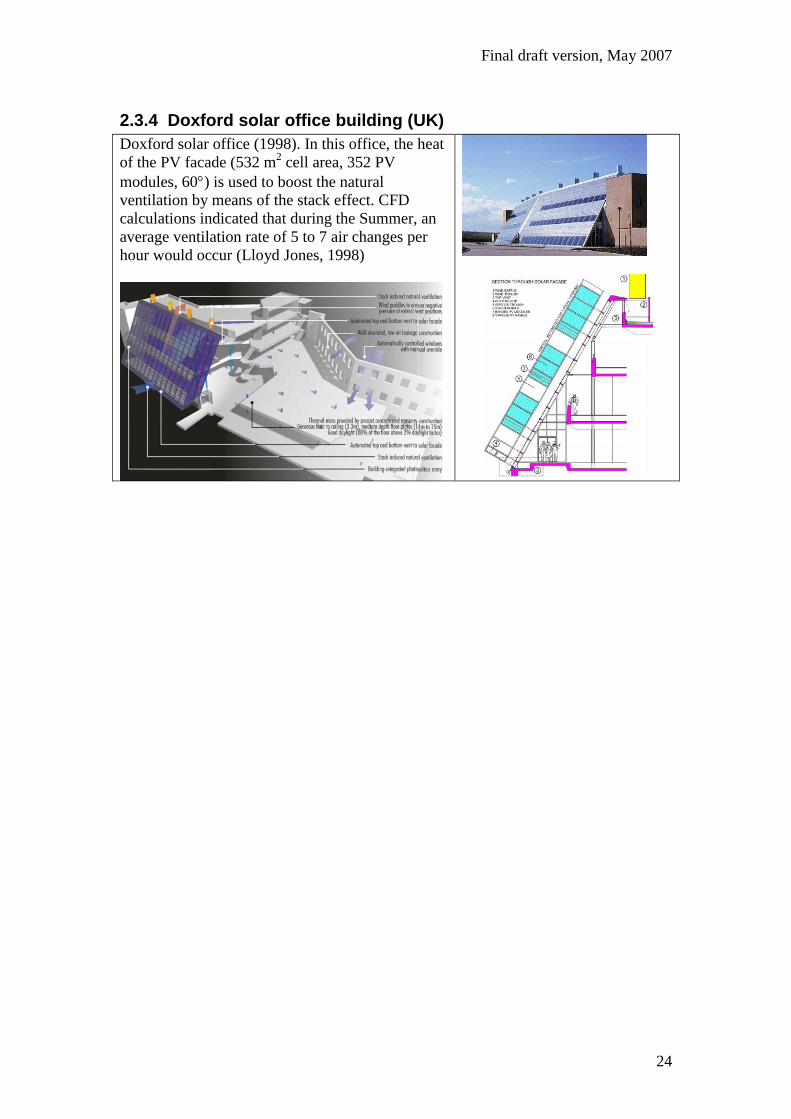
Doxford solar office (1998). In this office, the heat
of the PV facade (532 m2 cell area, 352 PV
modules, 60) is used to boost the natural
ventilation by means of the stack effect. CFD
calculations indicated that during the Summer, an
average ventilation rate of 5 to 7 air changes per
hour would occur (Lloyd Jones, 1998)
Final draft version, May 2007
25
2.3.5 MANCAT building (UK)
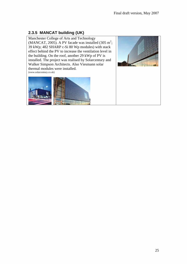
Manchester College of Arts and Technology
(MANCAT, 2005). A PV facade was installed (305 m2;
39 kWp; 482 SHARP c-Si 80 Wp modules) with stack
effect behind the PV to increase the ventilation level in
the building. On the roof, another 29 kWp of PV is
installed. The project was realised by Solarcentury and
Walker Simpson Architects. Also Viesmann solar
thermal modules were installed. (www.solarcentury.co.uk)
Final draft version, May 2007
26
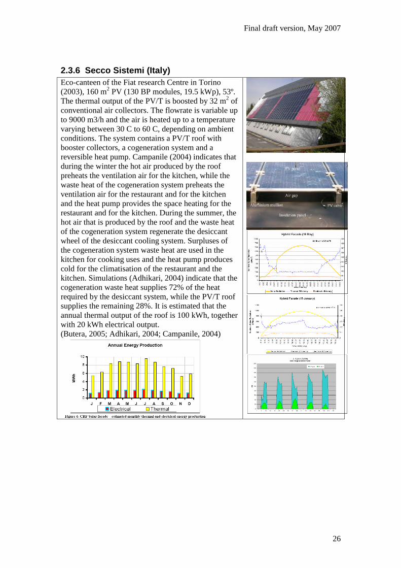
2.3.6 Secco Sistemi (Italy)
Eco-canteen of the Fiat research Centre in Torino
(2003), 160 m2 PV (130 BP modules, 19.5 kWp), 53º.
The thermal output of the PV/T is boosted by 32 m2 of
conventional air collectors. The flowrate is variable up
to 9000 m3/h and the air is heated up to a temperature
varying between 30 C to 60 C, depending on ambient
conditions. The system contains a PV/T roof with
booster collectors, a cogeneration system and a
reversible heat pump. Campanile (2004) indicates that
during the winter the hot air produced by the roof
preheats the ventilation air for the kitchen, while the
waste heat of the cogeneration system preheats the
ventilation air for the restaurant and for the kitchen
and the heat pump provides the space heating for the
restaurant and for the kitchen. During the summer, the
hot air that is produced by the roof and the waste heat
of the cogeneration system regenerate the desiccant
wheel of the desiccant cooling system. Surpluses of
the cogeneration system waste heat are used in the
kitchen for cooking uses and the heat pump produces
cold for the climatisation of the restaurant and the
kitchen. Simulations (Adhikari, 2004) indicate that the
cogeneration waste heat supplies 72% of the heat
required by the desiccant system, while the PV/T roof
supplies the remaining 28%. It is estimated that the
annual thermal output of the roof is 100 kWh, together
with 20 kWh electrical output.
(Butera, 2005; Adhikari, 2004; Campanile, 2004)

Final draft version, May 2007
27
Center of Professional Formation (CFP) of Casargo
(Lecco) (2005), 26 hybrid photovoltaic thermal panels
provide part of electric energy for the
building internal loads (23 m2, 3.9 kWp). The total
electrical energy produced by the PV/T plant amounts
to about 5 MWh/year and the thermal energy saved
amounts to about 8.7 MWh/year.
The output of the hybrid PV/T system is boosted by
the solar air system, placed at the top of the roof and
used for ventilation preheating. The total thermal
energy produced during the year is about 34.8 MWh,
that summed to thermal energy produced by PV/T
plant reaches 43.5 MWh/year, of which 21.2 MWh
during the heating period. Aste (2006) indicates that
the total cost of the multifunctional solar roof was
about € 250.000; about € 80.000 for the solar thermal
air system, € 90.000 for the solar thermal water system
and € 34.000 for the hybrid photovoltaic-thermal
plant. The graphs (from Aste, 2007) show the
calculated monthly electrical and thermal energy
production of an individual PV/T module and the
added contribution of the PV/T system to the air
collector system.

Final draft version, May 2007
28
2.3.7 Cenergia (Denmark)
Lundebjerg multifamily building (2000). In this
multifamily building (built late '60s, tenants, 27
apartments), that was renovated in 2000 after an
architectural competition (when it also received a
PV/T system), 5 different types of PV system were
tested. The 3 southern apartments receive heat from
the gable, 15 apartments receive preheated air from
the ventilation inlets, 3 receive ventilation air heated
by 1.7 m2 c-Si facade elements and the remaining 6
apartments do not receive heat but have PV powered
exhaust ventilation (see schematic drawing). The
ventilation inlet chimneys on the roof contain 7.7 m2
c-Si each and the gable contains a 52 m2 a-Si system
(2160 Wp). The a-Si system is grid connected (3
arrays with an inverter each) while the electrical
output of the c-Si chimney- and facade modules is
used to drive the DC ventilation fans (with backup
from the grid in case of insufficient irradiance,
controlled by a PV mixed developed in the project).
Dampers at the top of the gable open if no
preheating is needed. A grid is placed at the inlet
side of the gable to prevent entering of birds etc. The
flow is determined by the under pressure in the
apartment (exhaust flow 126m3/h, the average gable
inflow being 60% of this depending on wind and
open windows).
Due to the fact that the forced air flow in the
chimneys was of the order 0.5 m/s, the flowrate was
similar to the natural convection rate and the
imposed flow had little effect on the temperature.
This was also found for the gable. Blocking the
airflow behind the PV gable resulted in 16%
temperature increase.
It was concluded that the actual benefit of the
preheating to the apartments was low, due to large
losses of the unglazed PV/T, good ventilation heat
recovery in the apartments and low air speed, due to
the necessity to use wide air channels to enable
cooling in summer by natural convection flow.
(Jensen, 2001a)
Final draft version, May 2007
29
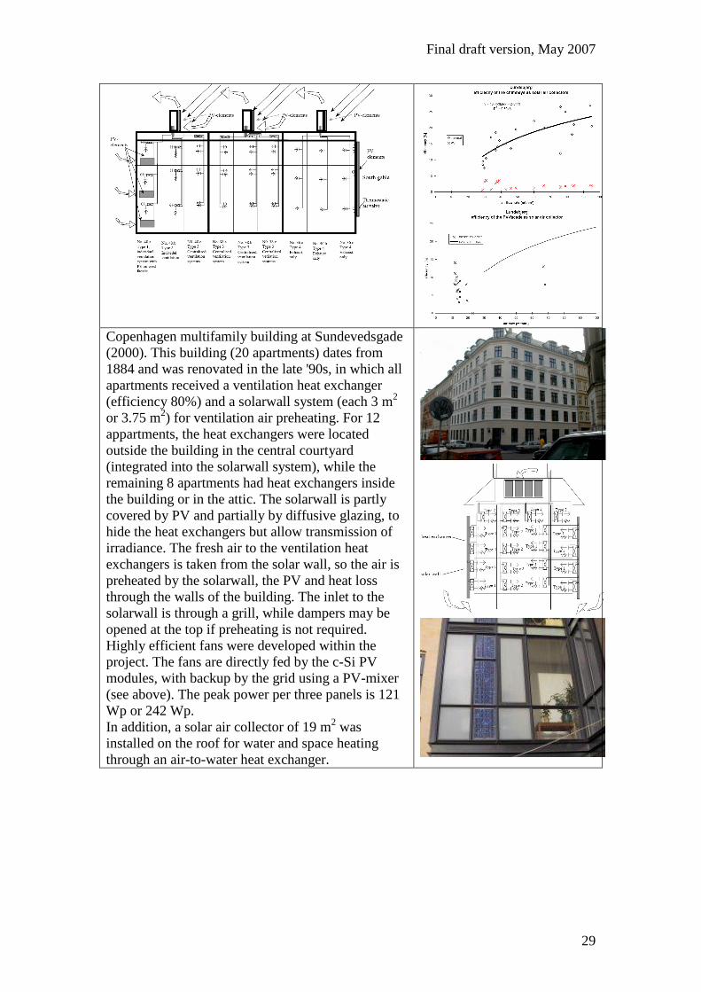
Copenhagen multifamily building at Sundevedsgade
(2000). This building (20 apartments) dates from
1884 and was renovated in the late '90s, in which all
apartments received a ventilation heat exchanger
(efficiency 80%) and a solarwall system (each 3 m2
or 3.75 m2) for ventilation air preheating. For 12
appartments, the heat exchangers were located
outside the building in the central courtyard
(integrated into the solarwall system), while the
remaining 8 apartments had heat exchangers inside
the building or in the attic. The solarwall is partly
covered by PV and partially by diffusive glazing, to
hide the heat exchangers but allow transmission of
irradiance. The fresh air to the ventilation heat
exchangers is taken from the solar wall, so the air is
preheated by the solarwall, the PV and heat loss
through the walls of the building. The inlet to the
solarwall is through a grill, while dampers may be
opened at the top if preheating is not required.
Highly efficient fans were developed within the
project. The fans are directly fed by the c-Si PV
modules, with backup by the grid using a PV-mixer
(see above). The peak power per three panels is 121
Wp or 242 Wp.
In addition, a solar air collector of 19 m2 was
installed on the roof for water and space heating
through an air-to-water heat exchanger.

Final draft version, May 2007
30
It was concluded that the benefit of the PV/T system
was small, especially since the losses to the system
were three times as large as the benefits from the
system; it was concluded that the system should
have been better insulated. The other conclusions
were similar to the Lundebjerg case.
(Jensen, 2001b)
Roskilde bank (2001) Two cases with each 24 c-Si
modules (98 Wp; 0.94 m2) on top of a solarwall
system under 15, installed on flat roof for
preheating of ventilation air and cooling of the PV.
During summer, the heat is vented to the ambient.
Total PV area 22.6 m2. Unlike case B, in case A the
PV has additional cooling riblets (see photo), which
were found to have a significant effect. (Jacobsen
and Jensen, 2001).

Final draft version, May 2007
31
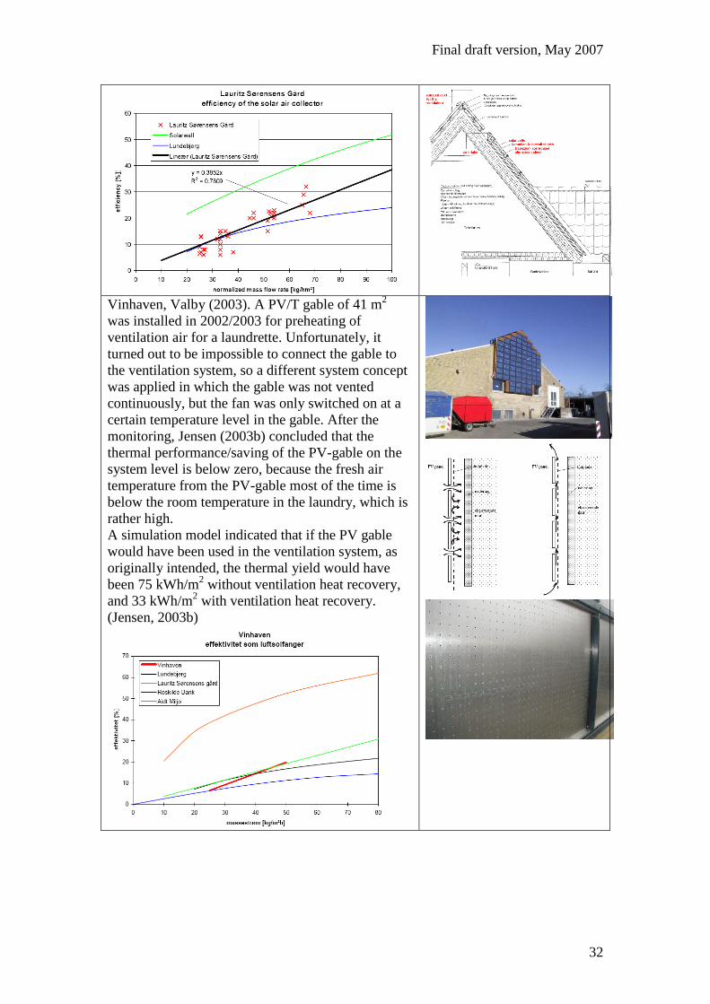
Lauritz Soerensens Gard (2002). The five storey
housing block dates from 1930 and was renovated in
2001-2002. Two collector areas were built above the
central staircases. The two systems consist of 35.3
m2 and 31.7 m
2 Solarwall collectors, of which
respectively 12.4 m2 and 11.4 m
2 are covered with
PV. The purpose is to preheat ventilation air during
winter and to cool the PV. The preheated air is
heated further by the ventilation heat recovery
system. Jensen (2003a) concludes that (a) the air
flow of fresh air to the building has no or minor
influence on the temperature of the PV-panels; the
air flow of fresh air seems not to increase the cooling
of the PV-panels already present by the buoyancy
driven air flow. (b) The part of the solar air collector
covered with PV-panels does not contribute to the
heating of the fresh air to the building. A poor
distribution of the air over the solar air collector due
to centrally located draw off from the solar air
collector decreases the performance of the solar air
collector at low mass flow rates. (c) The fresh air to
the building is also heated during the night due to the
heat loss from the building through the roof. From
the annual calculations, Jensen (2003a) finds that the
actual benefit of the preheating (day and night) in the
solar air collector is 1,235 kWh/year
while the heating of the fresh air in the solar air
collector is 7,620 kWh/year. The yield is thus
decreased by 84% due to the heat exchanger.
Without the preheating in the solar air collector 80%
of the heat in the exhaust air is recovered.
Due to the preheating this is increased to 82.5%. The
preheating in the solar air collector increases
thus the savings by 3%. The simulations shows an
annual preheating of the fresh air of 7,620 kWh for
both systems of which 35% is due to the sun while
65% is due to recovered heat loss through the roof
the solar air collector is mounted on. (Jensen, 2003a)
Final draft version, May 2007
32
Vinhaven, Valby (2003). A PV/T gable of 41 m2
was installed in 2002/2003 for preheating of
ventilation air for a laundrette. Unfortunately, it
turned out to be impossible to connect the gable to
the ventilation system, so a different system concept
was applied in which the gable was not vented
continuously, but the fan was only switched on at a
certain temperature level in the gable. After the
monitoring, Jensen (2003b) concluded that the
thermal performance/saving of the PV-gable on the
system level is below zero, because the fresh air
temperature from the PV-gable most of the time is
below the room temperature in the laundry, which is
rather high.
A simulation model indicated that if the PV gable
would have been used in the ventilation system, as
originally intended, the thermal yield would have
been 75 kWh/m2 without ventilation heat recovery,
and 33 kWh/m2 with ventilation heat recovery.
(Jensen, 2003b)
Final draft version, May 2007
33
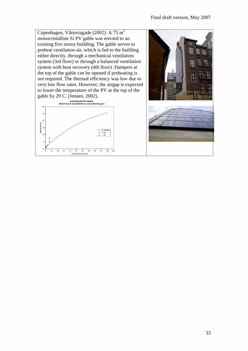
Copenhagen, Viktoriagade (2002). A 75 m2
monocristalline Si PV gable was erected to an
existing five storey building. The gable serves to
preheat ventilation air, which is fed to the building
either directly, through a mechanical ventilation
system (3rd floor) or through a balanced ventilation
system with heat recovery (4th floor). Dampers at
the top of the gable can be opened if preheating is
not required. The thermal efficiency was low due to
very low flow rates. However, the airgap is expected
to lower the temperature of the PV at the top of the
gable by 20 C. (Jensen, 2002).

Final draft version, May 2007
34
2.3.8 Arkitema (Denmark)
Silkeborgvej, Arhus (2003). The system contains 84
facade integrated cSi modules of 2.79 m2 (totaling
226 m2; 15 kWp), combined in 12 groups of 7
modules to the 12 inverters. The intention of the
system was preheating ventilation air and cooling of
the PV. The annual thermal yield of the PV/T
integrated over the entire facade was measured to be
13 kWh. (Katic, 2003)
Final draft version, May 2007
35
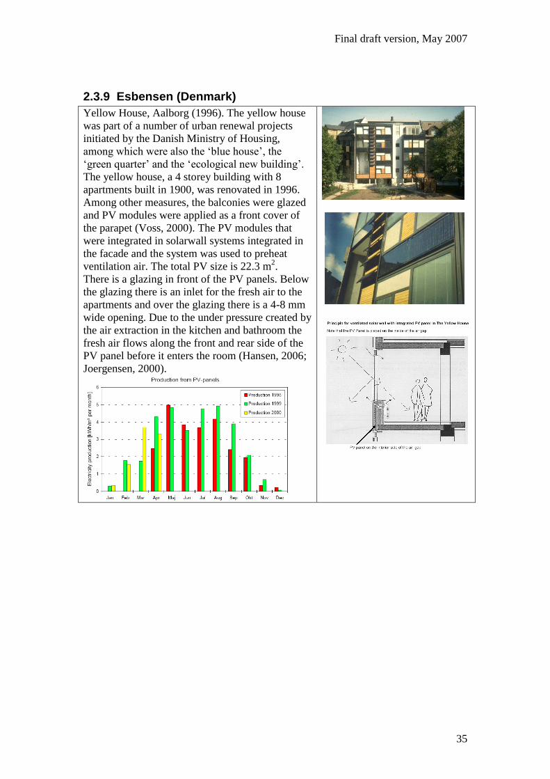
2.3.9 Esbensen (Denmark)
Yellow House, Aalborg (1996). The yellow house
was part of a number of urban renewal projects
initiated by the Danish Ministry of Housing,
among which were also the ‘blue house’, the
‘green quarter’ and the ‘ecological new building’.
The yellow house, a 4 storey building with 8
apartments built in 1900, was renovated in 1996.
Among other measures, the balconies were glazed
and PV modules were applied as a front cover of
the parapet (Voss, 2000). The PV modules that
were integrated in solarwall systems integrated in
the facade and the system was used to preheat
ventilation air. The total PV size is 22.3 m2.
There is a glazing in front of the PV panels. Below
the glazing there is an inlet for the fresh air to the
apartments and over the glazing there is a 4-8 mm
wide opening. Due to the under pressure created by
the air extraction in the kitchen and bathroom the
fresh air flows along the front and rear side of the
PV panel before it enters the room (Hansen, 2006;
Joergensen, 2000).
Final draft version, May 2007
36
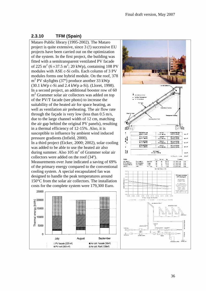
2.3.10 TFM (Spain)
Mataro Public library (1995-2002). The Mataro
project is quite extensive, since 3 (!) successive EU
projects have been carried out on the optimization
of the system. In the first project, the building was
fitted with a semitransparent ventilated PV facade
of 225 m2 (6 37.5 m
2; 20 kWp), containing 108 PV
modules with ASE c-Si cells. Each column of 3 PV
modules forms one hybrid module. On the roof, 378
m2 PV skylights (37º) produce another 33 kWp
(30.1 kWp c-Si and 2.4 kWp a-Si). (Lloret, 1998).
In a second project, an additional booster row of 60
m2 Grammer solar air collectors was added on top
of the PV/T facade (see photo) to increase the
suitability of the heated air for space heating, as
well as ventilation air preheating. The air flow rate
through the façade is very low (less than 0.5 m/s,
due to the large channel width of 12 cm, matching
the air gap behind the original PV panels), resulting
in a thermal efficiency of 12-15%. Also, it is
susceptible to influence by ambient wind induced
pressure gradients (Infield, 2000).
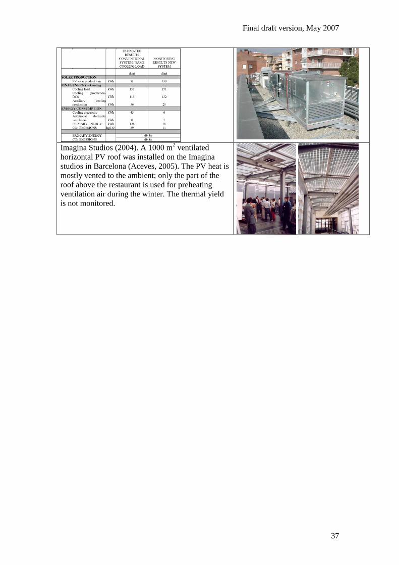
In a third project (Eicker, 2000; 2002), solar cooling
was added to be able to use the heated air also
during summer. Also 105 m2 of Grammer solar air
collectors were added on the roof (34º).
Measurements over June indicated a saving of 69%
of the primary energy compared to the conventional
cooling system. A special encapsulated fan was
designed to handle the peak temperatures around
150°C from the solar air collectors. The installation
costs for the complete system were 179,300 Euro.
Final draft version, May 2007
37
Imagina Studios (2004). A 1000 m2 ventilated
horizontal PV roof was installed on the Imagina
studios in Barcelona (Aceves, 2005). The PV heat is
mostly vented to the ambient; only the part of the
roof above the restaurant is used for preheating
ventilation air during the winter. The thermal yield
is not monitored.
Final draft version, May 2007
38
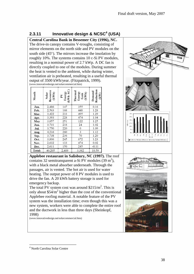
2.3.11 Innovative design & NCSC4 (USA)
Central Carolina Bank in Bessemer City (1996), NC. The drive-in canopy contains V-troughs, consisting of
mirror elements on the north side and PV modules on the
south side (45). The mirrors increase the insolation by
roughly 10%. The systems contains 10 c-Si PV modules,
resulting in a nominal power of 2.7 kWp. A DC fan is
directly coupled to one of the modules. During summer
the heat is vented to the ambient, while during winter,
ventilation air is preheated, resulting in a useful thermal
output of 3500 kWh/year. (Fitzpatrick, 1999). (www.innovativedesign.net/solarcommercial.htm)
Applebee restaurant in Salisbury, NC (1997). The roof
contains 32 semitransparent a-Si PV modules (39 m2),
with a black metal absorber underneath. Through the
passages, air is vented. The hot air is used for water
heating. The output power of 8 PV modules is used to
drive the fan. A 20 kWh battery storage is used for
emergency backup.
The total PV system cost was around $215/m2. This is
only about $54/m2 higher than the cost of the conventional
Applebee roofing material. A notable feature of the PV
system was the installation time; even though this was a
new system, workers were able to complete the entire roof
and the ductwork in less than three days (Sheinkopf,
1998) (www.innovativedesign.net/solarcommercial.htm)
4 North Carolina Solar Centre
Final draft version, May 2007
39
Final draft version, May 2007
40
2.4 Concentrating PV/T air collectors
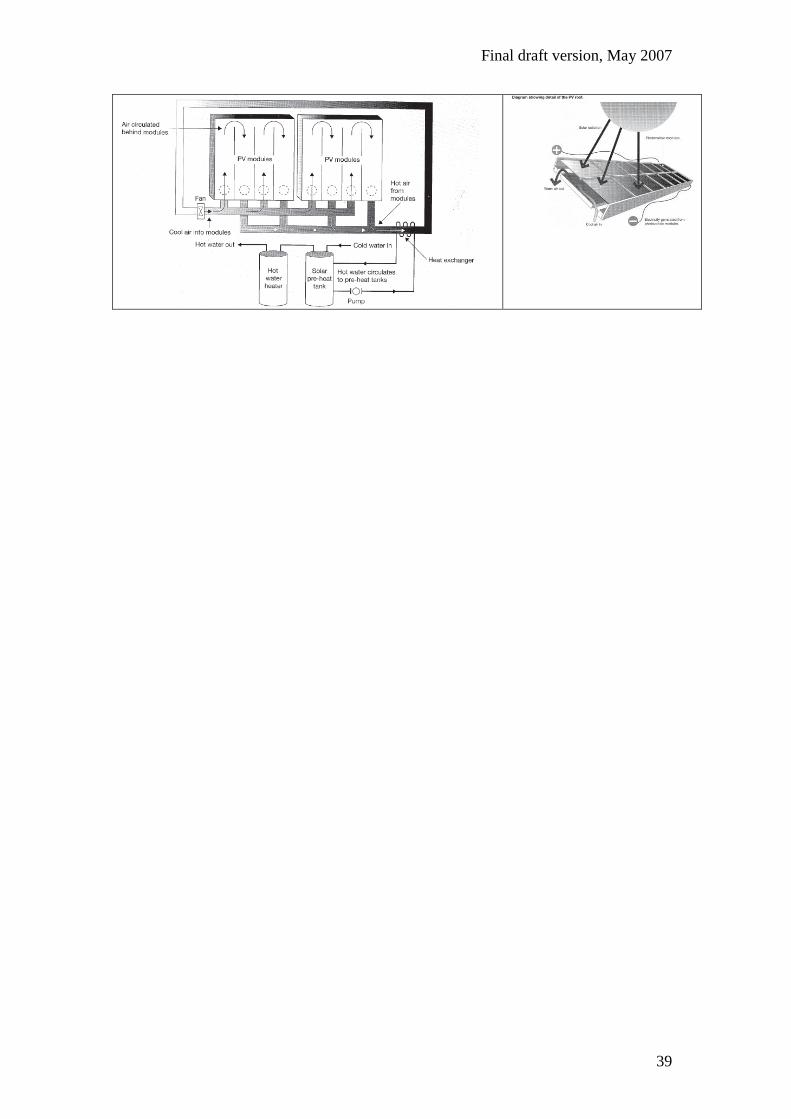
2.4.1 SunWatt Corp. (USA)
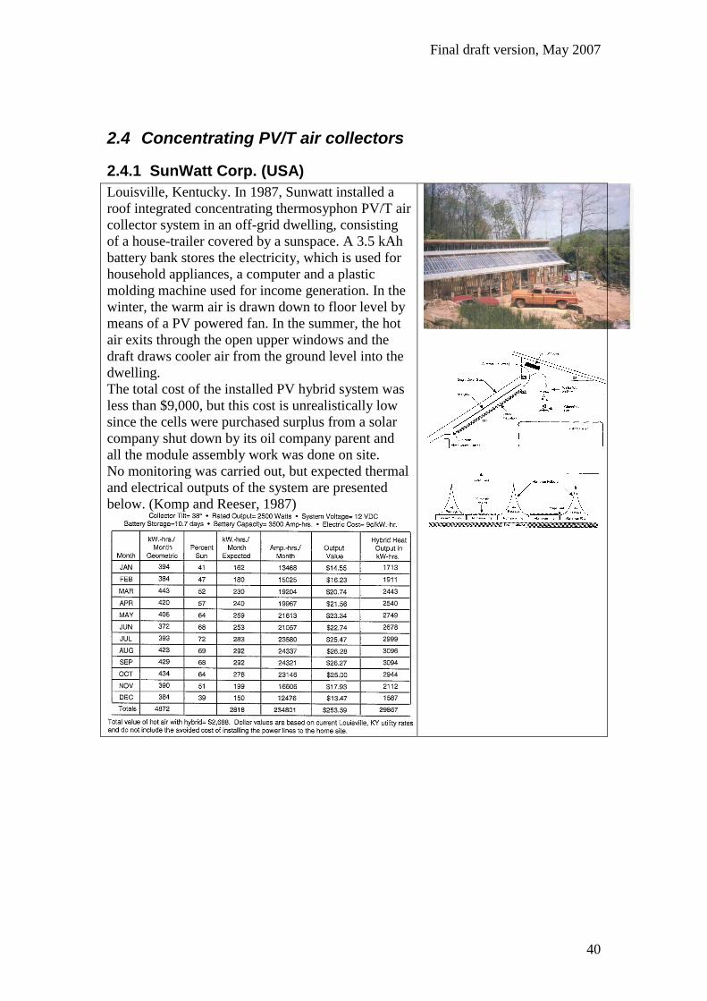
Louisville, Kentucky. In 1987, Sunwatt installed a
roof integrated concentrating thermosyphon PV/T air
collector system in an off-grid dwelling, consisting
of a house-trailer covered by a sunspace. A 3.5 kAh
battery bank stores the electricity, which is used for
household appliances, a computer and a plastic
molding machine used for income generation. In the
winter, the warm air is drawn down to floor level by
means of a PV powered fan. In the summer, the hot
air exits through the open upper windows and the
draft draws cooler air from the ground level into the
dwelling.
The total cost of the installed PV hybrid system was
less than $9,000, but this cost is unrealistically low
since the cells were purchased surplus from a solar
company shut down by its oil company parent and
all the module assembly work was done on site.
No monitoring was carried out, but expected thermal
and electrical outputs of the system are presented
below. (Komp and Reeser, 1987)
Final draft version, May 2007
41
3 PV/T liquid projects
3.1 Glazed PV/T liquid projects
3.1.1 Beaufort Court building (UK)
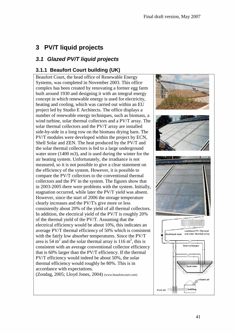
Beaufort Court, the head office of Renewable Energy
Systems, was completed in November 2003. This office
complex has been created by renovating a former egg farm
built around 1930 and designing it with an integral energy
concept in which renewable energy is used for electricity,
heating and cooling, which was carried out within an EU
project led by Studio E Architects. The office displays a
number of renewable energy techniques, such as biomass, a
wind turbine, solar thermal collectors and a PV/T array. The
solar thermal collectors and the PV/T array are installed
side-by-side in a long row on the biomass drying barn. The
PV/T modules were developed within the project by ECN,
Shell Solar and ZEN. The heat produced by the PV/T and
the solar thermal collectors is fed to a large underground
water store (1400 m3), and is used during the winter for the
air heating system. Unfortunately, the irradiance is not
measured, so it is not possible to give a clear statement on
the efficiency of the system. However, it is possible to
compare the PV/T collectors to the conventional thermal
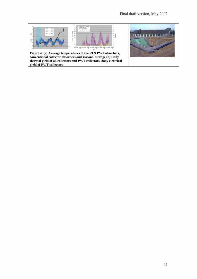
collectors and the PV in the system. The figures show that
in 2003-2005 there were problems with the system. Initially,
stagnation occurred, while later the PV/T yield was absent.
However, since the start of 2006 the storage temperature
clearly increases and the PV/T's give more or less
consistently about 20% of the yield of all thermal collectors.
In addition, the electrical yield of the PV/T is roughly 20%
of the thermal yield of the PV/T. Assuming that the
electrical efficiency would be about 10%, this indicates an
average PV/T thermal efficiency of 50% which is consistent
with the fairly low absorber temperatures. Since the PV/T
area is 54 m2 and the solar thermal array is 116 m
2, this is
consistent with an average conventional collector efficiency
that is 60% larger than the PV/T efficiency. If the thermal
PV/T efficiency would indeed be about 50%, the solar
thermal efficiency would roughly be 80%. This is in
accordance with expectations.
(Zondag, 2005; Lloyd Jones, 2004) (www.beaufortcourt.com)
Final draft version, May 2007
42
-10
0
10
20
30
40
50
60
30-jun-03 29-dec-03 29-jun-04 28-dec-04 29-jun-05 28-dec-05 29-jun-06 28-dec-06 29-jun-07 28-dec-07
date
Tem
pe
ratu
re (
C )
PVT1 PVT2
PVT3 PVT4
PVT5 PVT6
PVT7 coll 1
coll 2 storage
0
100
200
300
400
500
600
700
800
900
1000
30-jun-03 29-dec-
03
29-jun-04 28-dec-
04
29-jun-05 28-dec-
05
29-jun-06 28-dec-
06
29-jun-07 28-dec-
07
date
Da
ily Y
ield
(kW
h)
0
0.1
0.2
0.3
0.4
0.5
0.6
0.7
0.8
0.9
1
fraction
Thermal yield all collectors
Thermal yield PVT
Electrical yield PVT
ratio heat PVT/all_collectors
ratio PVT electrical/thermal
Figure 4: (a) Average temperatures of the RES PV/T absorbers,
conventional collector absorbers and seasonal storage (b) Daily
thermal yield of all collectors and PV/T collectors, daily electrical
yield of PV/T collectors
Final draft version, May 2007
43
3.1.2 PVTWINS
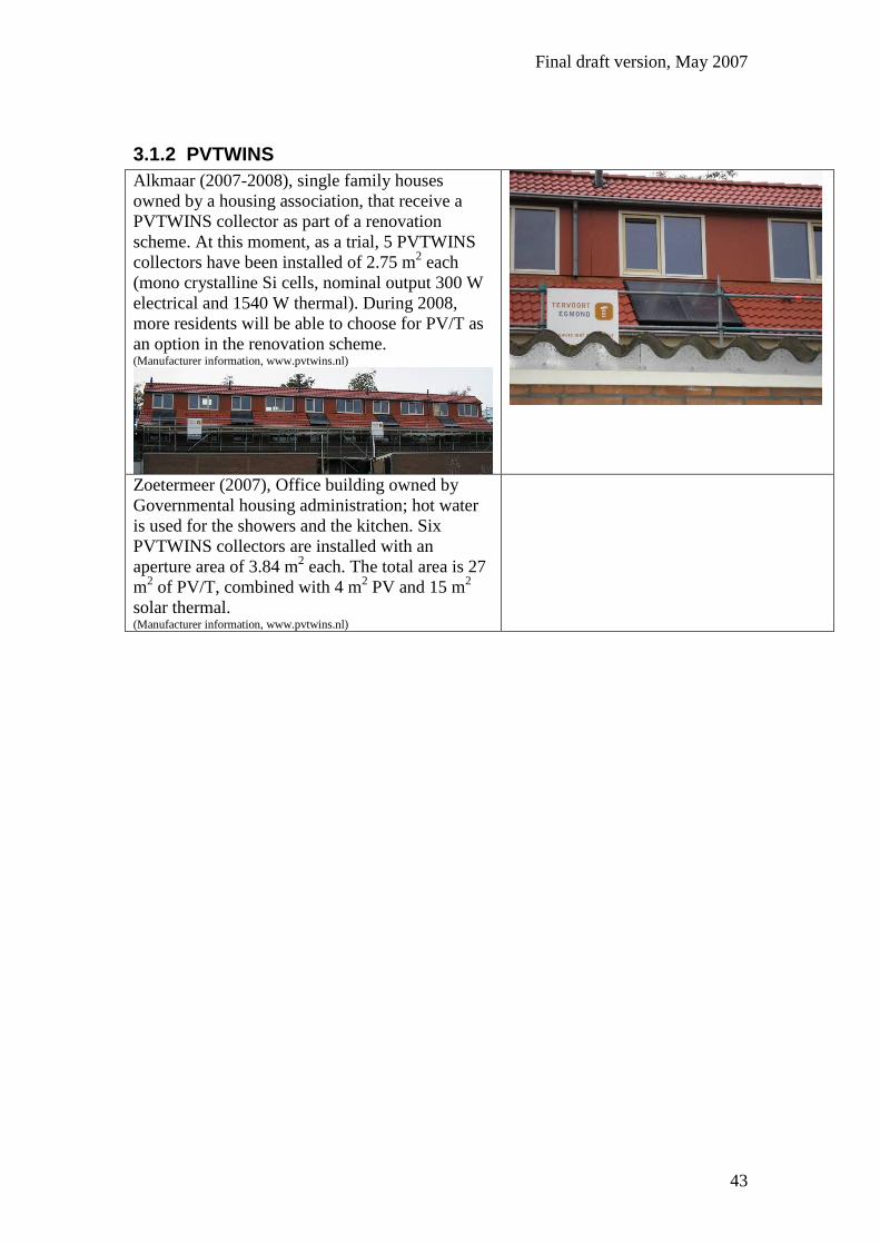
Alkmaar (2007-2008), single family houses
owned by a housing association, that receive a
PVTWINS collector as part of a renovation
scheme. At this moment, as a trial, 5 PVTWINS
collectors have been installed of 2.75 m2 each
(mono crystalline Si cells, nominal output 300 W
electrical and 1540 W thermal). During 2008,
more residents will be able to choose for PV/T as
an option in the renovation scheme. (Manufacturer information, www.pvtwins.nl)
Zoetermeer (2007), Office building owned by
Governmental housing administration; hot water
is used for the showers and the kitchen. Six
PVTWINS collectors are installed with an
aperture area of 3.84 m2 each. The total area is 27
m2 of PV/T, combined with 4 m
2 PV and 15 m
2
solar thermal. (Manufacturer information, www.pvtwins.nl)
Final draft version, May 2007
44
3.1.3 NSTDA5 (Thailand)
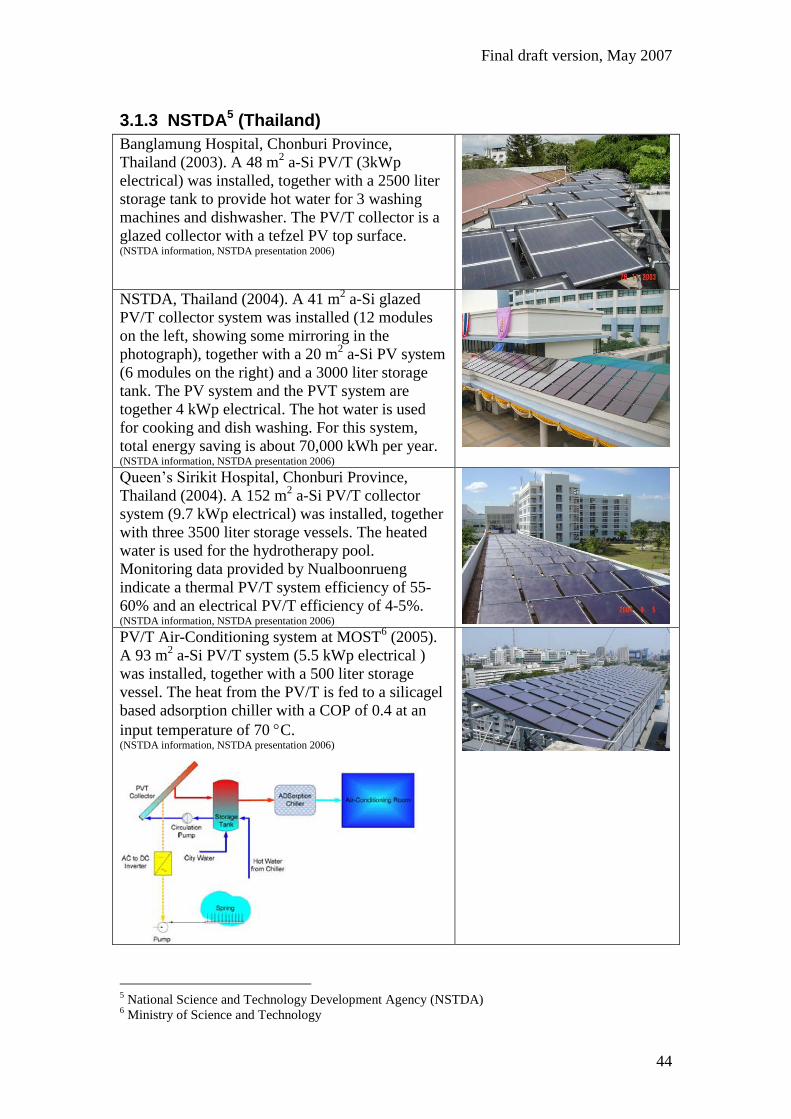
Banglamung Hospital, Chonburi Province,
Thailand (2003). A 48 m2 a-Si PV/T (3kWp
electrical) was installed, together with a 2500 liter
storage tank to provide hot water for 3 washing
machines and dishwasher. The PV/T collector is a
glazed collector with a tefzel PV top surface. (NSTDA information, NSTDA presentation 2006)
NSTDA, Thailand (2004). A 41 m2 a-Si glazed
PV/T collector system was installed (12 modules
on the left, showing some mirroring in the
photograph), together with a 20 m2 a-Si PV system
(6 modules on the right) and a 3000 liter storage
tank. The PV system and the PVT system are
together 4 kWp electrical. The hot water is used
for cooking and dish washing. For this system,
total energy saving is about 70,000 kWh per year. (NSTDA information, NSTDA presentation 2006)
Queen’s Sirikit Hospital, Chonburi Province,
Thailand (2004). A 152 m2 a-Si PV/T collector
system (9.7 kWp electrical) was installed, together
with three 3500 liter storage vessels. The heated
water is used for the hydrotherapy pool.
Monitoring data provided by Nualboonrueng
indicate a thermal PV/T system efficiency of 55-
60% and an electrical PV/T efficiency of 4-5%. (NSTDA information, NSTDA presentation 2006)
PV/T Air-Conditioning system at MOST6 (2005).
A 93 m2 a-Si PV/T system (5.5 kWp electrical )
was installed, together with a 500 liter storage
vessel. The heat from the PV/T is fed to a silicagel
based adsorption chiller with a COP of 0.4 at an
input temperature of 70 C. (NSTDA information, NSTDA presentation 2006)
5 National Science and Technology Development Agency (NSTDA)
6 Ministry of Science and Technology

Final draft version, May 2007
45
3.1.4 Hong Kong City University
Hong Kong (2007). A thermosyphon PVT
system was installed on a refurbished office
building of the Hong-Kong City University,
consisting of 6 PVT modules, module area
1.4 m2 (9 m
2 overall aperture area) and 0.5
m3 water storage. The PVT absorber consists
of an aluminium channel-plate. Typical
summer thermal efficiency is 40%, the hot
water is used for pantries and toilets. Each
module has 72 c-Si cells in series with a
packing factor of 58%. PV efficiency 8%; the
electrical output is stored in batteries and
through an inverter fed to the LED exit signs
of the building Chow, 2007).
Final draft version, May 2007
46
3.2 Unglazed PV/T liquid projects
3.2.1 NSTDA7 (Thailand)
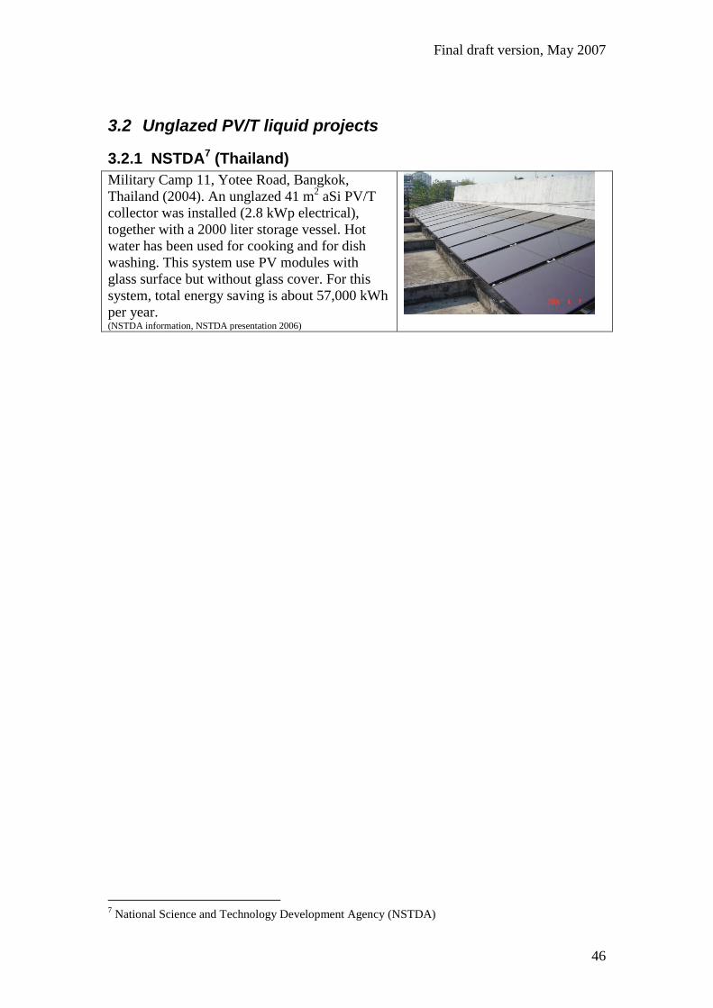
Military Camp 11, Yotee Road, Bangkok,
Thailand (2004). An unglazed 41 m2 aSi PV/T
collector was installed (2.8 kWp electrical),
together with a 2000 liter storage vessel. Hot
water has been used for cooking and for dish
washing. This system use PV modules with
glass surface but without glass cover. For this
system, total energy saving is about 57,000 kWh
per year. (NSTDA information, NSTDA presentation 2006)
7 National Science and Technology Development Agency (NSTDA)
Final draft version, May 2007
47
3.2.2 PVTWINS
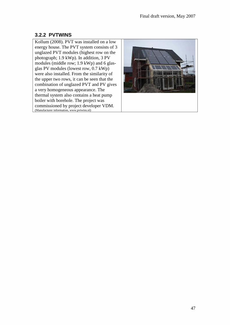
Kollum (2008). PVT was installed on a low
energy house. The PVT system consists of 3
unglazed PVT modules (highest row on the
photograph; 1.9 kWp). In addition, 3 PV
modules (middle row; 1.9 kWp) and 6 glas-
glas PV modules (lowest row, 0.7 kWp)
were also installed. From the similarity of
the upper two rows, it can be seen that the
combination of unglazed PVT and PV gives
a very homogeneous appearance. The
thermal system also contains a heat pump
boiler with borehole. The project was
commissioned by project developer VDM. (Manufacturer information, www.pvtwins.nl)
Final draft version, May 2007
48
3.3 Concentrating PV/T liquid collectors
3.3.1 SunWatt Corp. (USA)
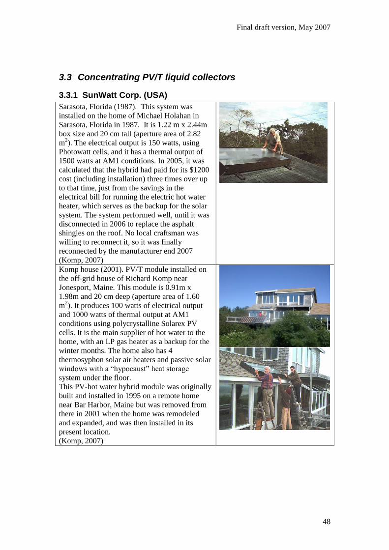
Sarasota, Florida (1987). This system was
installed on the home of Michael Holahan in
Sarasota, Florida in 1987. It is 1.22 m x 2.44m
box size and 20 cm tall (aperture area of 2.82
m2). The electrical output is 150 watts, using
Photowatt cells, and it has a thermal output of
1500 watts at AM1 conditions. In 2005, it was
calculated that the hybrid had paid for its $1200
cost (including installation) three times over up
to that time, just from the savings in the
electrical bill for running the electric hot water
heater, which serves as the backup for the solar
system. The system performed well, until it was
disconnected in 2006 to replace the asphalt
shingles on the roof. No local craftsman was
willing to reconnect it, so it was finally
reconnected by the manufacturer end 2007
(Komp, 2007)
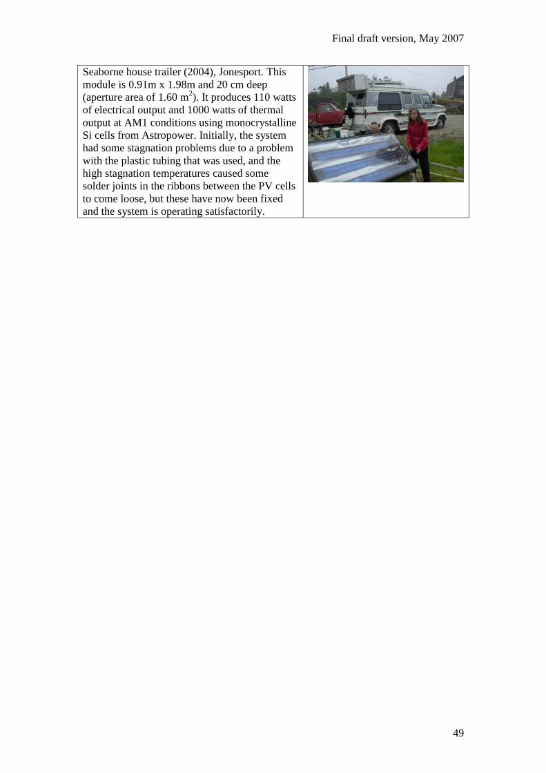
Komp house (2001). PV/T module installed on
the off-grid house of Richard Komp near
Jonesport, Maine. This module is 0.91m x
1.98m and 20 cm deep (aperture area of 1.60
m2). It produces 100 watts of electrical output
and 1000 watts of thermal output at AM1
conditions using polycrystalline Solarex PV
cells. It is the main supplier of hot water to the
home, with an LP gas heater as a backup for the
winter months. The home also has 4
thermosyphon solar air heaters and passive solar
windows with a “hypocaust” heat storage
system under the floor.
This PV-hot water hybrid module was originally
built and installed in 1995 on a remote home
near Bar Harbor, Maine but was removed from
there in 2001 when the home was remodeled
and expanded, and was then installed in its
present location.
(Komp, 2007)
Final draft version, May 2007
49
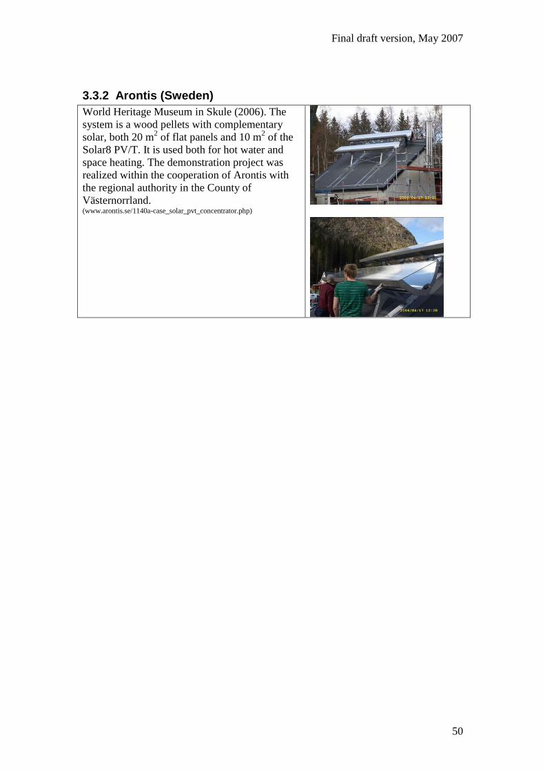
Seaborne house trailer (2004), Jonesport. This
module is 0.91m x 1.98m and 20 cm deep
(aperture area of 1.60 m2). It produces 110 watts
of electrical output and 1000 watts of thermal
output at AM1 conditions using monocrystalline
Si cells from Astropower. Initially, the system
had some stagnation problems due to a problem
with the plastic tubing that was used, and the
high stagnation temperatures caused some
solder joints in the ribbons between the PV cells
to come loose, but these have now been fixed
and the system is operating satisfactorily.
Final draft version, May 2007
50
3.3.2 Arontis (Sweden)
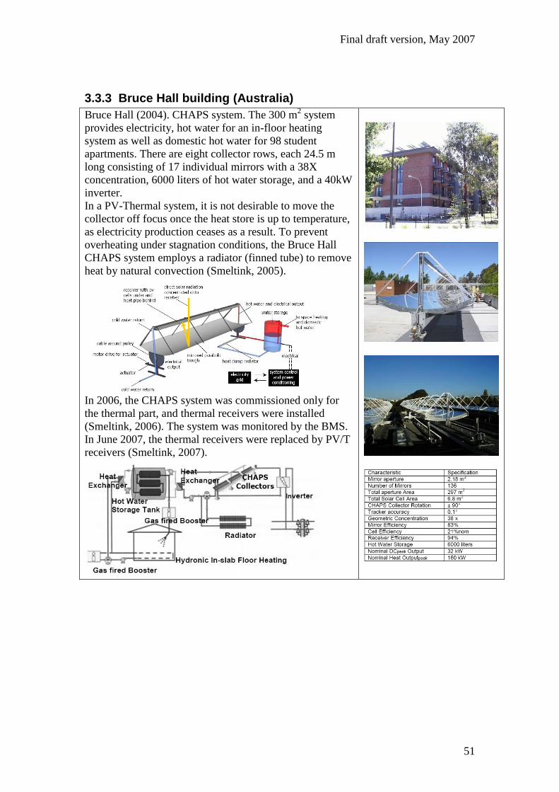
World Heritage Museum in Skule (2006). The
system is a wood pellets with complementary
solar, both 20 m2 of flat panels and 10 m
2 of the
Solar8 PV/T. It is used both for hot water and
space heating. The demonstration project was
realized within the cooperation of Arontis with
the regional authority in the County of
Västernorrland. (www.arontis.se/1140a-case_solar_pvt_concentrator.php)
Final draft version, May 2007
51
3.3.3 Bruce Hall building (Australia)
Bruce Hall (2004). CHAPS system. The 300 m2 system
provides electricity, hot water for an in-floor heating
system as well as domestic hot water for 98 student
apartments. There are eight collector rows, each 24.5 m
long consisting of 17 individual mirrors with a 38X
concentration, 6000 liters of hot water storage, and a 40kW
inverter.
In a PV-Thermal system, it is not desirable to move the
collector off focus once the heat store is up to temperature,
as electricity production ceases as a result. To prevent
overheating under stagnation conditions, the Bruce Hall
CHAPS system employs a radiator (finned tube) to remove
heat by natural convection (Smeltink, 2005).
In 2006, the CHAPS system was commissioned only for
the thermal part, and thermal receivers were installed
(Smeltink, 2006). The system was monitored by the BMS.
In June 2007, the thermal receivers were replaced by PV/T
receivers (Smeltink, 2007).

Final draft version, May 2007
52
Final draft version, May 2007
53
4 PV/T combined air&liquid projects
4.1 Millennium Electric & Solor (Israel)
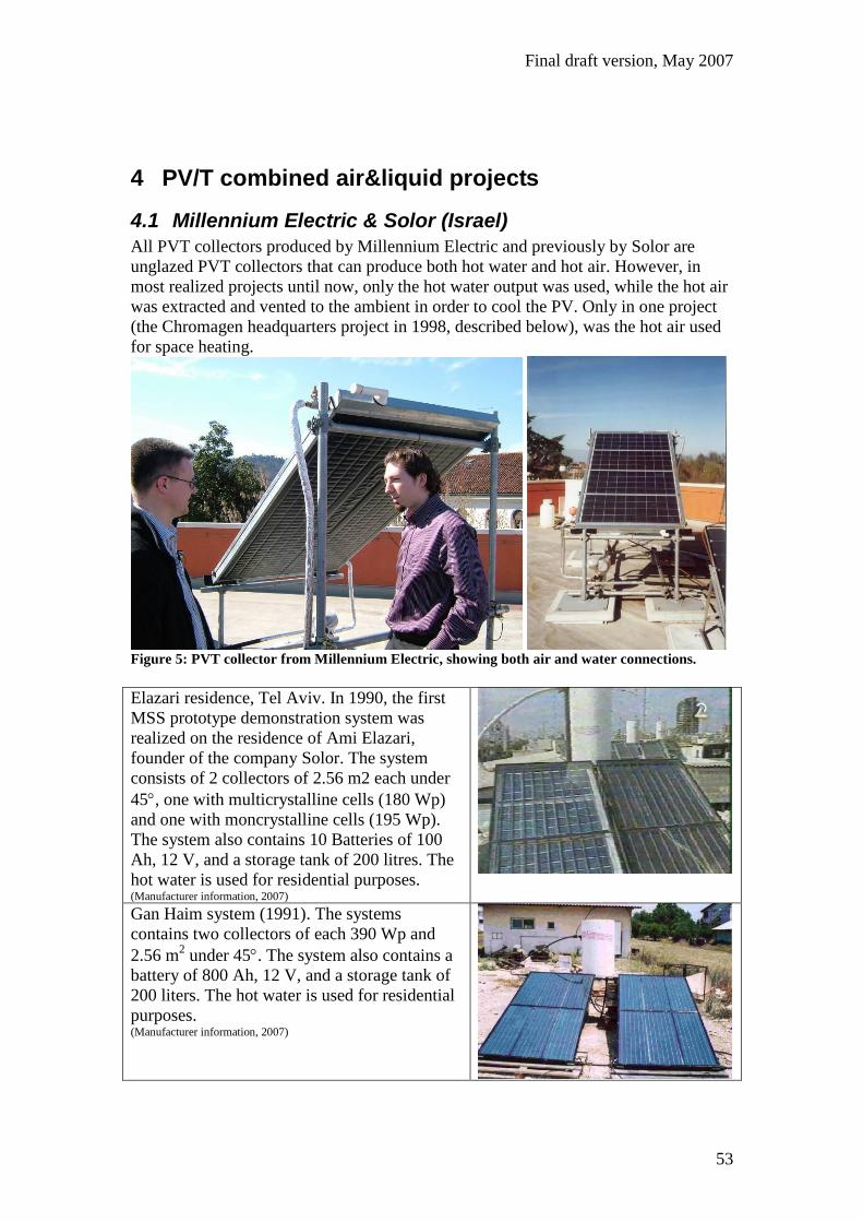
All PVT collectors produced by Millennium Electric and previously by Solor are
unglazed PVT collectors that can produce both hot water and hot air. However, in
most realized projects until now, only the hot water output was used, while the hot air
was extracted and vented to the ambient in order to cool the PV. Only in one project
(the Chromagen headquarters project in 1998, described below), was the hot air used
for space heating.
Figure 5: PVT collector from Millennium Electric, showing both air and water connections.
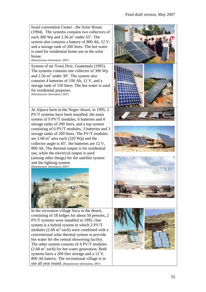
Elazari residence, Tel Aviv. In 1990, the first
MSS prototype demonstration system was
realized on the residence of Ami Elazari,
founder of the company Solor. The system
consists of 2 collectors of 2.56 m2 each under
45, one with multicrystalline cells (180 Wp)
and one with moncrystalline cells (195 Wp).
The system also contains 10 Batteries of 100
Ah, 12 V, and a storage tank of 200 litres. The
hot water is used for residential purposes. (Manufacturer information, 2007)
Gan Haim system (1991). The systems
contains two collectors of each 390 Wp and
2.56 m2 under 45. The system also contains a
battery of 800 Ah, 12 V, and a storage tank of
200 liters. The hot water is used for residential
purposes. (Manufacturer information, 2007)

Final draft version, May 2007
54
Klil village. In 1992, 6 residences received a
PV/T system (the houses of the families
Nezger, Shenar, Rotem, Hovev, Brown and
Levy). In addition, the Shenar family received
a second system in 1995. Klil village is located
in the mountains in the North of Israel and is
not connected to the national grid. Most of the
systems consist of 2 PV/T modules of 2.68 m2
area each, but two systems consist of 3 PV/T
modules (the system of the Rotem family and
the second system of the Shenar family). The
systems all have a water storage of 200 liters
and a 12 V, 800 Ah battery to provide the
energy demand of the families autonomously.
The electricity is used for electric lighting, a
TV, a refrigerator and a washing machine,
while the thermal output is used for residential
use (e.g shower). The PV/T modules are 320
Wp electrical, have a thermal production of
roughly 1200-1500 Wp thermal and have been
installed under an angle of 55. (Manufacturer information, 2007)
Rotem family house
Brown family house
Nezger family house
Shenar family house (system 1)
Hovev family house
Levy family house
At the UNosom forces base in Somalia in
1993, a MSS PV/T system was installed
consisting of 2 modules of 2.68 m2 each under
an angle of 30, with a 200 liters storage vessel
and a 12 V, 800 Ah battery. The thermal output
is used for residential purposes. (Manufacturer information, 2007)
Final draft version, May 2007
55
Israel convention Center - the Solar House
(1994). The systems contains two collectors of
each 300 Wp and 2.56 m2 under 55. The
system also contains a battery of 800 Ah, 12 V,
and a storage tank of 200 litres. The hot water
is used for residential home use in the solar
house. (Manufacturer information, 2007)
System of mr Yossi Dvir, Guatemala (1995).
The systems contains one collector of 300 Wp
and 2.56 m2 under 30. The system also
contains 4 batteries of 100 Ah, 12 V, and a
storage tank of 150 liters. The hot water is used
for residential purposes. (Manufacturer information, 2007)
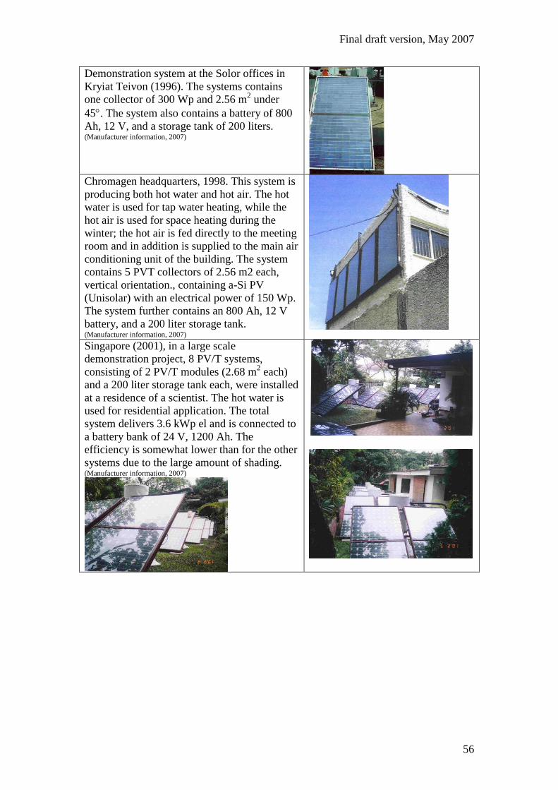
At Alpaca farm in the Negev desert, in 1995, 2
PV/T systems have been installed; the main
system of 9 PV/T modules, 6 batteries and 4
storage tanks of 200 liters, and a top system
consisting of 6 PV/T modules, 3 batteries and 3
storage tanks of 200 liters. The PV/T modules
are 2.68 m2 area each (320 Wp) and the
collector angle is 45, the batteries are 12 V,
800 Ah. The thermal output is for residential
use, while the electrical output is used
(among other things) for the satellite system
and the lighting system. (Manufacturer information, 2007)
In the recreation village Suca in the desert,
consisting of 18 lodges for about 50 persons, 2
PV/T systems were installed in 1995. One
system is a hybrid system in which 2 PV/T
modules (2.68 m2 each) were combined with a
conventional solar thermal system to provide
hot water for the central showering facility.
The other system consists of 4 PV/T modules
(2.68 m2 each) for hot water generation. Both
systems have a 200 liter storage and a 12 V,
800 Ah battery. The recreational village is in
use all year round. (Manufacturer information, 2007)
Final draft version, May 2007
56
Demonstration system at the Solor offices in
Kryiat Teivon (1996). The systems contains
one collector of 300 Wp and 2.56 m2 under
45. The system also contains a battery of 800
Ah, 12 V, and a storage tank of 200 liters. (Manufacturer information, 2007)
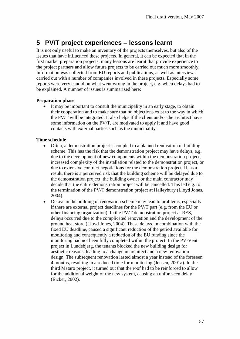
Chromagen headquarters, 1998. This system is
producing both hot water and hot air. The hot
water is used for tap water heating, while the
hot air is used for space heating during the
winter; the hot air is fed directly to the meeting
room and in addition is supplied to the main air
conditioning unit of the building. The system
contains 5 PVT collectors of 2.56 m2 each,
vertical orientation., containing a-Si PV
(Unisolar) with an electrical power of 150 Wp.
The system further contains an 800 Ah, 12 V
battery, and a 200 liter storage tank. (Manufacturer information, 2007)
Singapore (2001), in a large scale
demonstration project, 8 PV/T systems,
consisting of 2 PV/T modules (2.68 m2 each)
and a 200 liter storage tank each, were installed
at a residence of a scientist. The hot water is
used for residential application. The total
system delivers 3.6 kWp el and is connected to
a battery bank of 24 V, 1200 Ah. The
efficiency is somewhat lower than for the other
systems due to the large amount of shading. (Manufacturer information, 2007)
Final draft version, May 2007
57
5 PV/T project experiences – lessons learnt It is not only useful to make an inventory of the projects themselves, but also of the
issues that have influenced these projects. In general, it can be expected that in the
first market preparation projects, many lessons are learnt that provide experience to
the project partners and allow future projects to be carried out much more smoothly.
Information was collected from EU reports and publications, as well as interviews
carried out with a number of companies involved in these projects. Especially some
reports were very candid on what went wrong in the project, e.g. when delays had to
be explained. A number of issues is summarized here:
Preparation phase
It may be important to consult the municipality in an early stage, to obtain
their cooperation and to make sure that no objections exist to the way in which
the PV/T will be integrated. It also helps if the client and/or the architect have
some information on the PV/T, are motivated to apply it and have good
contacts with external parties such as the municipality.
Time schedule
Often, a demonstration project is coupled to a planned renovation or building
scheme. This has the risk that the demonstration project may have delays, e.g.
due to the development of new components within the demonstration project,
increased complexity of the installation related to the demonstration project, or
due to extensive contract negotiations for the demonstration project. If, as a
result, there is a perceived risk that the building scheme will be delayed due to
the demonstration project, the building owner or the main contractor may
decide that the entire demonstration project will be cancelled. This led e.g. to
the termination of the PV/T demonstration project at Haileybury (Lloyd Jones,
2004).
Delays in the building or renovation scheme may lead to problems, especially
if there are external project deadlines for the PV/T part (e.g. from the EU or
other financing organization). In the PV/T demonstration project at RES,
delays occurred due to the complicated renovation and the development of the
ground heat store (Lloyd Jones, 2004). These delays, in combination with the
fixed EU deadline, caused a significant reduction of the period available for
monitoring and consequently a reduction of the EU funding since the
monitoring had not been fully completed within the project. In the PV-Vent
project in Lundebjerg, the tenants blocked the new building design for
aesthetic reasons, leading to a change in architect and a new renovation
design. The subsequent renovation lasted almost a year instead of the foreseen
4 months, resulting in a reduced time for monitoring (Jensen, 2001a). In the
third Mataro project, it turned out that the roof had to be reinforced to allow
for the additional weight of the new system, causing an unforeseen delay
(Eicker, 2002).
Final draft version, May 2007
58
Application of new components & techniques
New developments within the projects sometimes take more time than
expected. Examples are the development of a PV-mixer8 in the PV-Vent
projects (the initial prototype was found to be faulty and a new company was
found to redesign the component) or the ground heat storage in the RES
project (the completion of which took 6 months instead of the anticipated 6
weeks (Lloyd Jones, 2004)). Also, these components may be less energy
saving, more costly or more difficult to apply than expected due to
unanticipated problems (such as unanticipated material characteristics, leaking
or a non-optimal control strategy).
Additional requirements may come up during the project related to e.g. safety.
In the RES project, for the design of the ground heat store, after it was decided
that this would have a floating lid, a substantial amount of time went into the
issue of designing the system thus that the water reservoir is absolutely safe
(against the risk of injury or drowning to people including trespassing children
for example), which made it essential that there should be no chance of anyone
easily being able to enter the water even in the case of partial or total collapse
of the floating lid following unplanned loss of water (Lloyd Jones, 2004). In
the third Mataro project, a legionella crisis in Mataro retarded the installation
of the solar desiccant cooling. For almost a month, the system was stopped to
disinfect the humidifiers in accordance with the legionella legislation, but the
report indicates that the worries about legionella problems could finally be
rebutted since it was found that it is impossible to bring bacterias from
humidifier water into the air flow due to the fact that legionellas can’t survive
at the low operation temperature of about 18°C (Eicker, 2002).
The fact that innovative techniques are used in a demonstration project may
require the use of non-standard components. Since these components may be
new and little experience is acquired with them, this may lead to mistakes or
other problems, as well as long delivery times. As an example, in the RES
project, since it was decided to keep the voltage of the PV/T collectors low (to
prevent the use of bypass diodes), special low-voltage inverters were used that
later turned out to give problems. By that time, however, the inverter
manufacturer had decided to stop the development of these inverters, and had
no infrastructure left to solve these problems. The problems were only solved
when the inverters were replaced. Due to the fact that the new invertors had
different specifications, a redesign of the electrical connections of the PV/T
system was required (Lloyd Jones, 2004).
The fitting of the PV/T installation to the existing installation may turn out to
be more problematic than expected. In the Third Mataro project, the air
volume flow was limited by the existing ducting system (Eicker, 2002).
Another example is the ecological launderette in Valby, Copenhagen, that was
fitted with a PV/T-air gable. It turned out that it was not possible to connect
the PV/T-air gable to the existing ventilation installation. Instead, the PV/T
system was redesigned such that a separate fan, leading the heated air from the
gable to the building, was only switched on if the gable temperature was high
enough. In practice, however, this solution turned out to be much less energy
saving than the original design; even to such an extent that the savings were
8 A device that was developed within the project to feed the fan of the ventilation systems as much as
possible directly by the PV, but that allowed backup by the grid in case of insufficient solar supply.

Final draft version, May 2007
59
actually negative due to the high room temperatures in the launderette (Jensen,
2003).
When going from a prototype collector to a full system installation, if a one-
of-a-kind system is installed, many practical issues may come up. As an
example, in a publication on the ANU project (concentrating PV/T system
with tracking), several faults were described that were encountered and
rectified during commissioning: pivot mount interference, cable durability,
guide sheave seizure, faulty temperature sensors, leaks, actuator noise and
BMS calibration. In the Sørensensvej PV/T-air project, an always-open bypass
was found in a ventilation air heat exchanger, while in another the ducting was
connected wrongly. Also in liquid collector systems, heat exchangers
connected in reverse are a classical installation error. Sometimes such errors
are discovered in the commissioning phase, sometimes they can only be found
after monitoring of the actual system performance.
The mounting of the system is frequently problematic, due to special demands
for the integration from the architect, adaptations that have to be made due to
specific building characteristics or the issue of guaranteeing rainproof
integration of the PV/T system. Also discussion on stability of the mounting
construction at high wind load may occur. In the Sørensensvej project, the
following description is given: “It was originally the idea to use the principles
in the BPS guidelines for integration of solar collectors into the roof. There
rainproof solutions are obtained by using roofing-felt as under roofing.
However, in practice it has been difficult to convince the architects about these
solutions [..].” Nevertheless, since the uniform visual aspect of PV/T is an
important selling point, it is important to think of good integration options.
The production of substantial numbers of in the project developed
components, such as PV/T modules, may be difficult to realize. Since the
production of these special components in standard production lines may
cause too much interference, often the prototype production technique and
production facilities have to be applied (possibly in a slightly adapted form to
allow a significant quantity), and consequently the products are expensive. In
the RES project, this was also reason to reduce the number of PV/T collectors
from 22 to 7, and to add 15 conventional solar-thermal collectors to
compensate for this reduction (Lloyd Jones, 2004).
Monitoring and troubleshooting
The fact that during the building process many actors may be only for a short
time at the building place and have a limited responsibility may give
problems. The RES report gives the following description: “The
commissioning and monitoring of the systems has taken almost a year due to
the sequential nature of problem solving in novel technologies. The resolution
of one issue often leads to the discovery of another. The reasons for the
defects are sometimes not clear, and responsibilities are blurred. The
commitment to getting these issues resolved well after the end of the building
contract is difficult to maintain. The contractors are expected to solve
problems on a fixed price contract. It is possible that a separate budget should
be allocated for this input.” (Lloyd Jones, 2004)
The monitoring may have problems due to malfunctioning or wrongly
calibrated sensors, as well as data loss e.g. due to the effect of power cuts on
the monitoring computer. An example is the monitoring of Sørensensvej,

Final draft version, May 2007
60
which the report author describes as follows: “The systems at Lauritz
Sørensensvej 24 have from a measuring point of view been a nightmare.
Nearly all possible errors that can be imagined were present in the systems
after the installation and they were corrected very late – almost a year after
installation.” In the PV-Vent project at Sundevedsgade (Jesen, 2001b), it was
found that the 4-quadrant analogue multiplier was very sensitive to
temperature and gave unreliable measurements. In the RES project, it was
decided not to install a pyranometer to reduce the transgression of the budget.
Often, little or no funding and time is left for the monitoring, so often no
reliable data on the system performance are available and possible installation
errors may go unnoticed. At the other hand, in some projects fully automated
monitoring systems have been set up, also making the monitored data directly
publicly accessible trough a website, as is the case in the RES project.
Although the project was finished years ago, newly monitored data still
becomes available every day, which was found to be very useful.
The energy savings of the PV/T system may be less than anticipated due to the
fact that the design of the module or system is not optimised. Shading may
reduce the performance, especially the electrical output. In building integrated
PV/T-air systems, this is often related to the wide air gap that is present behind
the PV, to allow sufficient cooling of the PV by natural convection during the
summer, when preheating ventilation air is not useful, as is e.g. the case in the
first Mataro library project (Infield, 2000) and in the PV-Vent projects at
Lundebjerg (Jensen, 2001a) and Sundevedsgade (Jensen, 2001b). The wide air
gap results in very low flow velocities, that are largely determined by the
natural convection flow and that are very susceptible to ambient wind
pressure; in the Mataro library project, it was even found that for an Easterly
wind direction, the airflow through the cavity is downwards (Infield, 2000). In
addition, in the PV-vent project, it was found that the electrical benefits of the
cooling of the PV were insignificant. The PV-Vent studies also indicate that
the potential of preheating ventilation air is substantially reduced if a good
ventilation heat exchanger is used (Jensen, 2001a). Finally, the Sørensensvej
project (Jensen, 2003) indicated a reduced performance at low mass flow due
to a poor flow distribution caused by central draw off of the air. Also, pressure
drops may be higher than expected, e.g. due to too dense filters, as found in
the second Mataro library project (Infield, 2000), or wrongly placed sound
absorbers, as was found in the third Mataro project (Eicker, 2002). This leads
to increased fan power consumption and may also increase the noise level of
the fan, requiring additional sound absorbers. At the other hand, it was also
found that the yield was in some projects higher than anticipated, due to the
fact that also the heat losses from the building were recaptured by the PV/T;
because of this effect in the PV-Vent project the PV/T-air façade system saved
energy even at night (Jensen, 2001a). However, this effect is reduced if the
building insulation is improved.
Important in PV air systems for preheating ventilation air, is that the air is only
preheated during the heating season. In practice, it may happen that the bypass
is not functioning properly, resulting in preheated air also during summer, as
was found in the monitoring in the third Mataro project, leading to an increase
in the cooling energy required (Eicker, 2002).
Final draft version, May 2007
61
Installation phase
In glazed PV/T systems, the issue of high temperatures may be significant. A
lengthy stagnation period may occur during the period in which the collectors
are present on the building site but not yet connected. In the RES project, the
manufacturer requested the coverage of the PV/T collectors during this period,
to minimize any chance of trouble (Lloyd Jones, 2004). Another issue was
raised in the third Mataro project, in which the glazed booster air collectors
could at times supply peak temperatures of 150 C, while the maximum
temperature of the sorption wheel of the solar cooling system was 90 C; this
was solved with an additional bypass (Eicker, 2002).
Although in principle it is possible to control and monitor the PV/T collector
system by the BMS9, it is often more convenient for the collector system to
have its own control and monitoring. Problems may result due to a long BMS
setup period extending significantly beyond the installation of the PV/T
collectors, BMS failures, incorrect control procedures or insufficient sampling
rate. In the ANU project, the BMS was programmed to recognize fault
conditions for the concentrating PV/T system, but since the interface between
the BMS and the collector was not connected for a significant time, during
which time the collectors could only be operated under staff supervision
(Smeltink and Blakers, 2006).
Dissemination
Dissemination is important and may be realized by means of flyers, brochures,
a website (where the abovementioned leaflets can also be downloaded), and
group visits to the PV/T installation, if applicable. Furthermore, monitoring
reports and conference papers are very worthwhile to spread information on
the project. Unfortunately, the dissemination of project- and monitoring
reports (e.g. final technical reports from EU supported projects) is often far
from optimal. Often, information on the project can be incorporated in a
broader public relations scheme of one or more of the parties involved.
A number of lessons can be retrieved from this list:
Realize beforehand that the planning of the existing building or renovation
project has its own dynamics; substantial delays may occur during this process
and it is wise to allow for these in the planning of the deadline of the PV/T
project. Also, substantial delays in the PV/T project compromising the
commissioning date of the building can often not be tolerated.
It is an important asset if the architect, building owner, local authorities and
other parties in the building process are convinced from the start of the
importance of the PV/T system to the project, are motivated to apply and it
have sufficient knowledge about it.
Safety issues, roof mounting and roof integration issues, responsibility issues
and warranties may take a substantial amount of time in the project.
Limit the amount of new components in the project, since the larger the
amount of components to be developed within the project, the larger the
chance that delays may occur. If the central item in the demonstration is the
PV/T, then try to use standard components for the other aspects as much as
possible. In addition, be aware that the production of a large number of non-
9 Building Monitoring System
Final draft version, May 2007
62
standard components (including possibly the PV/T modules itself) may be
costly and not easy to realize.
Be aware that a lengthy installation period (including BMS programming if
relevant for the PV/T) should not compromise the PV/T reliability or
performance too much.
Monitoring is crucial to detect errors in the installation, which are often caused
by malfunctioning components. This is particularly relevant if these errors
substantially reduce the energy saving function of the system, e.g. by requiring
too much electrical power for pumps and fans, or compromising the control of
the system due to malfunctioning sensors, valves or bypasses. Allow sufficient
time and money for monitoring and be aware that in this phase also time
should be available to change malfunctioning components and malfunctioning
monitoring sensors, and it should be clear whose responsibility it is to make
these changes. In addition, it is highly recommended to set up an automated
monitoring environment that can be read through a (publicly accessible)
website.
Dissemination is very important and can be realized by various means, ranging
from allowing group visits to websites and publications in magazines or
conference proceedings.
Final draft version, May 2007
63
6 Conclusions The market development for PV-Thermal systems is still in an early stage, which is in
marked contrast to the large application potential of these systems, in particular on
multifamily buildings where the available space is limited. Very important at this
early stage is the generation of awareness for PV/T systems and the establishment of
best practices and confidence through realized PV/T installations. The results of
demonstration projects should be published widely.
A large amount of PV/T systems has been installed over the last 20 years. All
together, the report presents information on 70 realised PV/T installations. Most of
these systems are PV/T-air systems (39 systems), but also 15 PV/T-liquid systems
were found, as well as 16 PV/T-liquid & air systems. Most of the PV/T-air projects
have been built by the German manufacturer Grammer Solar using their unglazed
PV/T-air collector. Another large number of projects was realized in national Danish
projects led by the Danish consultant Cenergia, applying ventilated PV facades with
heat recovery, as well as Solarwall systems. The oldest residential PV/T air
installation found in the project was realized in the USA by Sunwatt in 1987; it is still
in operation.
With respect to liquid collectors, a number of systems was realised recently in
Thailand, in which 5 large-scale PV/T systems were installed on various
governmental buildings over a period of about 2 years (2003-2004). These systems
have been developed by NSTDA and are mostly unglazed PV/T collectors using
amorphous silicon, but in one project also glazed PV/T collectors were used. The
largest of these systems is a 152 m2 system on the Queen Sirikit hospital in Chonburi.
Other projects to be mentioned are a 54 m2 glazed PV/T liquid project that was
realised by the Dutch companies ECN, Shell Solar and ZEN Solar in the UK in 2003.
This PV/T work has been continued by the ECN spin off company PVTWINS, that in
2007 has realized a 27 m2 glazed PV/T liquid system on a Dutch governmental
building and five 2.8 m2 systems in a residential renovation project, while more
market introduction projects have been planned for 2008.
With respect to the PVT systems heating both liquid and air, a large number of
systems was realized by the company Solor, that has realized projects with unglazed
PV/T collectors from 1991 onwards, among which several PV/T systems installed at 6
off-grid residences in Klil village, 2 PV/T systems in a recreation village in the Negev
desert and 2 PV/T systems on an alpaca farm. Since 1999, the PV/T activities of Solor
have been taken over by Millennium Electric, that is now marketing these systems.
Concluding, it can be stated that PV/T is an interesting technique with a large
potential and a large amount of experience on PV/T is available. After a long market
preparation phase in PV/T development, we hope that the results obtained in this task
will contribute to the final take-off of the PV/T market.
Finally, while some demonstration projects run smoothly, others may be plagued by
various unforeseen problems. From the reports on the various demonstration projects,
a number of lessons has been learnt:
Realize beforehand that the PV/T project is in many cases additional to an
existing building project or renovation project, that has its own dynamics;
substantial delays may occur during this process and it is wise to allow for
these in the planning of the deadline of the PV/T project. Also, substantial

Final draft version, May 2007
64
delays in the PV/T project compromising the commissioning date of the
building can often not be tolerated.
It is an important asset if the architect, building owner, local authorities and
other parties in the building process are convinced from the start of the
importance of the PV/T system to the project, are motivated to apply and it
have sufficient knowledge about it.
Safety issues, roof mounting and roof integration issues, responsibility issues
and warranties may take a substantial amount of time in the project.
Limit the amount of new components in the project, since the larger the
amount of components to be developed within the project, the larger the
chance that delays may occur. If the central item in the demonstration is the
PV/T, then try to use standard components for the other aspects as much as
possible. In addition, be aware that the production of a large number of non-
standard components (including possibly the PV/T modules itself) may be
costly and not easy to realize.
Monitoring is crucial to detect errors in the installation, which are often caused
by malfunctioning components (sensors, bypasses, etc). This is particularly
relevant if these errors substantially reduce the energy saving function of the
system, e.g. by requiring too much electrical power for pumps and fans, or
compromising the control of the system due to malfunctioning sensors, valves
or bypasses. Allow sufficient time and money for monitoring and be aware
that in this phase also time should be available to change malfunctioning
components and malfunctioning monitoring sensors, and it should be clear
whose responsibility it is to make these changes. In addition, it is highly
recommended to set up an automated monitoring environment that can be read
through a (publicly accessible) website.
Dissemination is very important and can be realized by various means, ranging
from allowing group visits to websites and publications in magazines or
conference proceedings.

Final draft version, May 2007
65
Final draft version, May 2007
66
7 References 1. Aceves, O., Llorach, E., Barbat, E., Genard, P., Hentschel, D., Orti, A., Berga,
E. (2005), "1000 m2 of Hybrid PV-Thermal ventilated semi-transparent roof in
a TV studios Imagina Visual Center (Esplugues-Barcelona)", last news
presentation at PVSEC 2005, Barcelona.
2. Aschehoug (2003), BP SOLAR SKIN, a facade concept for a sustainable
future, report Sintef.
3. Aste, N. (2007), Retrofit solare: l' esperienza del centro di formazione
professionale di Casargo - A multifunctional solar plant, Next Energy
conference 2007, Turin, Italy. www.nextenergy.biz/wvAttachments/695_Aste.pdf
4. Butera, F., Aste, N., Adhikari, R.S. and Bracco, R (2005), Ecomensa project at
CRF: Performance of solar façade, 600 Congresso Nazionale ATI, Rome
5. Campanile, P., Parodi, M.L., Menardi, L., Mola, S., Bracco, R (2004),
Efficient integration of solar energy, trigeneration and desiccant cooling: the
'ECO-canteen' of CRF, DAME-BC Warshaw workshop
6. Cartmell, Shankland, Fiala, Hanby (2004), A multi-operational ventilated
photovoltaic and solar air collector: application, simulation and initial
monitoring feedback, SE 76 (2004), pp 45-53.
7. Coventry, J.S. (2004), A solar concentrating photovoltaic / thermal collector,
PhD thesis Australian National University.
8. Eicker, U., Fux, V., Infield, D., Mei, L. (2000), Heating and cooling potential
of combined photovoltaic-solar air collector facades, 16th EPSEC Glasgow
9. Eicker, U. (2002), Adsorption cooling of buildings with integrated PV/solar
air heating facades - AIRCOOL final report for project ERK6-CT1999-00010
10. Eicker, U., Huber, M., Schürger, U., Schumacher, J., Trinkle, A. (2003),
Desiccant cooling technology powered by solar thermal air collector systems
ISES Solar World Congress, Goteborg
11. Elazari, A. (1997), Solar multimodule for electrical and hot water supply for
residentially building, SES Solar World Congress Korea
12. Infield, D. (2000), Design, study and experimental evaluation of an integrated
solar facade, final report for project JOR3-CT97-0185.
13. Jacobsen, T.D, Jensen. S.Ø. (2001), Solassisteret ventilation – målinger på
PVT-anlæg hos Roskilde Bank. report Solar Energy Centre Denmark, Danish
Technological Institute. www.buildvision.dk/pdf/solassisteret_ventilation_maalinger_paa_pvt_anlaeg_hos_roskilde_bank.pdf
14. Jensen, S.Ø. (2001a), Results from measurements on the PV-VENT systems at
Lundebjerg, report Solar Energy Centre Denmark, Danish Technological
Institute. www.buildvision.dk/pdf/results_from_measurements_on_the_pvvent_systems_at_lundebjerg.pdf.
15. Jensen, S.Ø. (2001b), Results from measurements on the PV-VENT systems at
Sundevedsgade/Tøndergade, report Solar Energy Centre Denmark, Danish
Technological Institute.
16. Jensen, S.Ø. (2002), Måling af den termiske funktion af en multifunktionel
solcellegavl, report Solar Energy Centre Denmark, Danish Technological
17. Jensen, S.Ø. (2003a), Results from measurements on a roof integrated PV
system with preheating of fresh air. Lauritz Sørensens Gård, report Solar
Energy Centre Denmark, Danish Technological Institute. www.buildvision.dk/pdf/results_from_measurements_on_a_roof_integrated_pv_system_with_preheating_of_fresh_air.pdf.

Final draft version, May 2007
67
18. Jensen, S.Ø. (2003b), Måling på solcellegavl med forvarmning af
ventilationsluft Økologisk vaskeri - Vinhaven, Valby, report Solar Energy
Centre Denmark, Danish Technological Institute.
19. Jørgensen, O.B., Nielsen, L.T. (2000), Monitored results from the yellow
house, Eurosun 2000 conference, Denmark.
20. Katic, I., Badran, J. (2003), Solcelleanlæg på Silkeborgvej i Århus
Målerapport for perioden april 2002 til marts 2003, report Solar Energy Centre
Denmark, Danish Technological Institute.
21. Komp, R., Reeser, T. (1987), Design, construction & operation of a PV/Hot air
hybrid energy system, ISES Solar World Congress Hamburg.
22. Kropf, S. (2003), PV/T Schiefer, Optimierung der Energieeffizienz von
Gebäuden durch gegenseitige Ergänzung von Simulation und Messung am
Beispiel der Hinterlüftung gebäudeintegrierter Photovoltaik, PhD report ETH
Zurich
23. Lloret, A., Andreu, J., Merten, J., Puigdollers, J., Aceves, O., Sabata, L.,
Chantant, M., Eicker, U. (1998), Large grid-connected hybrid PV system
integrated in a public building, PIP 6, pp. 453-464
24. Lloyd Jones, D., Matson, C., Pearsall, N.M. (1998), The solar office: a solar
powered building with a comprehensive energy strategy, 2nd WCPEC,
Vienna, Austria.
25. Lloyd Jones, D. (2000), The solar office Doxford International, ETSU report www.berr.gov.uk/files/file17275.pdf
26. Lloyd Jones, D. (2004), Renewable Energy Systems head office and visitors’
facility, Final Technical Report EU contract NNE5-1999-00352.
27. NSTDA (2007), PVT Solar system in Thailand, presentation NSTDA.
28. Phongsitong, J., Jaikla, S., Nualboonrueng, T., Sichanugrist, P. (2006), The
Performance of a-Si Photovoltaic / Thermal Solar Air-Conditioning System
Working With Compressed Refrigerant Air-Conditioning System, PVSEC,
Dresden.
29. Posnansky, M., Gnos, S. and Coonen, S. (1994), The importance of hybrid
PV-building integration, WCPEC 1994, Hawaii.
30. Posnansky, M., Eckmanns, A. and Szacsvay, T. (1997), Cogeneration of
electricity and heat on building integrated PV-power systems: practical results,
14th PVSEC, Barcelona.
31. Robert Hastings, S. (1999), Solar Air Systems - Built examples, James &
James
32. Shankland, Lomas, Carmell, Reeve, Dotzler (2001), A Ventilated Photovoltaic
and Solar-Air Collector for Space and Water Heating, CISBE national
conference, UK.
33. Sheinkopf (1998), PV system with thermal heat recovery, CADDET
newsletter, May 1998.
34. Smeltink, J.F.H., Blakers, A.W. and Coventry (2005), A 40kW roof mounted
PV Thermal concentrator system, PVSEC Conference, Barcelona.
35. Smeltink, J.F.H. and Blakers, A.W. (2006), 40kW PV Thermal roof mounted
concentrator system, WCPEC Conference, Hawaii.
36. Smeltink, J.F.H. and Blakers, A.W. (2007), Performance monitoring of a PV
Thermal concentrator system, PVSEC Conference, Milan.
37. Voss, K. (2000), Solar energy in building renovation — results and experience
of international demonstration buildings, Energy and Buildings 32 (2000) pp.
291–302.

Final draft version, May 2007
68
38. Zondag, H.A., Bristow, N., Gramsbergen, E., Helden, W.G.J. van, Lloyd-
Jones, D., Nelson, S., Soerensen, H., Watts, B., Zolingen, R.J.C. van (2005),
The Beaufort Court energy system - PVT and solar thermal for the preheating
of ventilation air, ESTEC 2005 Freiburg.
39. www.solarwall.com
40. www.ecn.nl/egon/extra/extranet/pvt-platform/het-pvt-platform
41. www.beaufortcourt.com
42. www.grammer-solar.de
43. www.innovativedesign.net/solarcommercial_a.htm
44. www.pvtwins.nl


![Bouwfysica Principes van thermische bruggen - schock.nl6107].pdf · Bouwfysica Principes van thermische bruggen. Meer informatie vindt u in ons bouwfysica portaal. . Inhoudsopgave](https://static.fdocuments.nl/doc/165x107/5a7b31d27f8b9a66798bd5e3/bouwfysica-principes-van-thermische-bruggen-6107pdfbouwfysica-principes-van.jpg)