cod. 3541S180 - Rev. 05 - 10/2019
204
IT Manuale d’Installazione e Uso RO Manual de instalare şi utilizare EN Installation and Use Manual RU Руководство по установке и эксплуатации ES Manual de instalación y uso PL Instrukcja instalacji i obsługi FR Notice d’installation et d’utilisation NL Handleiding voor installatie en gebruik cod. 3541S180 - Rev. 05 - 10/2019
Transcript of cod. 3541S180 - Rev. 05 - 10/2019

IT Manuale d’Installazione e Uso RO Manual de instalare şi utilizareEN Installation and Use Manual RU Руководство по установке и эксплуатацииES Manual de instalación y uso PL Instrukcja instalacji i obsługiFR Notice d’installation et d’utilisation NL Handleiding voor installatie en gebruik
cod.
354
1S18
0 -
Rev
. 05
- 1
0/20
19

3ITcod. 3541S180 - Rev. 05 - 10/2019
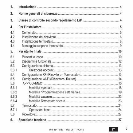
1. Introduzione ..................................................................................................... 4
2. Norme generali di sicurezza ........................................................................... 4
3. Classe di controllo secondo regolamento ErP ............................................. 4
4. Per l’installatore ............................................................................................... 54.1 Contenuto ...................................................................................................... 54.2 Installazione del ricevitore ............................................................................. 64.3 Installazione termostato ................................................................................. 84.4 Montaggio supporto termostato ..................................................................... 95. Per utente finale ............................................................................................. 105.1 Pulsanti e Icone ........................................................................................... 105.2 Diagramma funzionale ................................................................................. 125.3 Configurazione sistema ............................................................................... 135.3.1 Creazione account .............................................................................. 135.4 Configurazione RF (Ricevitore - Termostato) .............................................. 135.5 Configurazione Wi-Fi (Ricevitore- Router) ................................................... 145.6 APPCOИИECT .......................................................................................... 155.6.1 Modalità manuale ................................................................................ 185.6.2 Modalità “Programmazione settimanale .............................................. 195.6.3 Modalità vacanze ................................................................................ 235.6.4 Modalità Termostato spento ................................................................ 235.7 Termostato ................................................................................................... 245.7.1 Operazioni base .................................................................................. 245.8 Ricevitore ..................................................................................................... 276. Specifiche tecniche ....................................................................................... 27
4 IT cod. 3541S180 - Rev. 05 - 10/2019
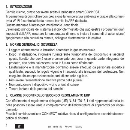
1. INtroduzIoNEGentilecliente,grazieperaveresceltoiltermostatosmartCOИИECT.Ti permetterà di controllare con precisione la temperatura ambiente e grazie alla connet-tività Wi-Fi è controllabile da remoto tramite la APP dedicata.Questomanualeèintesoperinstallatorieutentifinale.L’elemento principale del sistema è il cronotermostato che può gestire i programmi orari impostati dall’APP, misurare la temperatura di zona e inviare i comandi di accensione/spegnimento alla centralina remota, collegata direttamente alla caldaia.
2. NormE gENEralI dI SICurEzza• Leggere attentamente le istruzioni contenute in questo manuale• Dopo l’installazione, informare l’utente sulle funzionalità del dispositivo e lasciargli
questo libretto che dovrà essere conservato con cura in quanto parte integrante del prodotto, che potrà poi essere usato in futuro come riferimento
• L’installazione e la manutenzione dovranno essere effettuati da personale esperto e qualificato,secondoleregolevigentieinaccordoalleistruzionidelcostruttore.Noneseguire alcune operazione sulle parti di controllo sigillate.
• Rimuovere l’alimentazione elettrica prima della pulizia.• Nonposizionareildispositivovicinoafontidicalore.• Tenere lontano dalla portata dei bambini
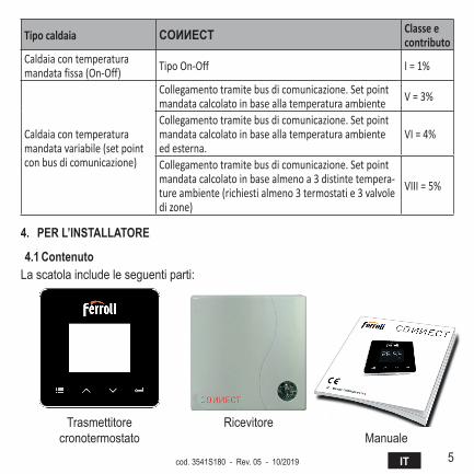
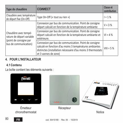
3. ClaSSE dI CoNtrollo SECoNdo rEgolamENto ErPConriferimentoalregolamentodelegato(UE)N.811/2013,idatirappresentatinellata-bella possono essere usati a completamento dell’etichettatura di apparecchi per riscal-damento.PossibilicombinazioniconCOИИECT,relativeclassidiconfigurazioneecontributoener-getico al sistema.
5ITcod. 3541S180 - Rev. 05 - 10/2019
Tipo caldaia COИИECT Classe e contributo
Caldaia con temperatura mandata fissa (On-Off) Tipo On-Off I = 1%
Caldaia con temperatura mandata variabile (set point con bus di comunicazione)
Collegamento tramite bus di comunicazione. Set point mandata calcolato in base alla temperatura ambiente V = 3%
Collegamento tramite bus di comunicazione. Set point mandata calcolato in base alla temperatura ambiente ed esterna.
VI = 4%
Collegamento tramite bus di comunicazione. Set point mandata calcolato in base almeno a 3 distinte tempera-ture ambiente (richiesti almeno 3 termostati e 3 valvole di zone)
VIII = 5%
4. PEr l’INStallatorE
4.1 ContenutoLa scatola include le seguenti parti:
Trasmettitorecronotermostato
RicevitoreManuale
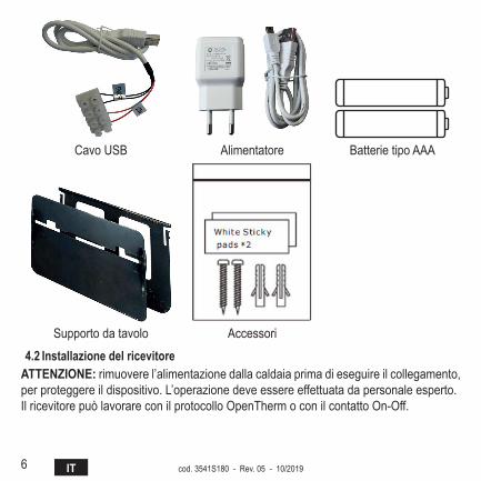
6 IT cod. 3541S180 - Rev. 05 - 10/2019
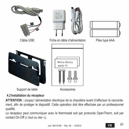
Cavo USB Alimentatore Batterie tipo AAA
Supporto da tavolo Accessori
4.2 Installazione del ricevitoreattENzIoNE: rimuovere l’alimentazione dalla caldaia prima di eseguire il collegamento, per proteggere il dispositivo. L’operazione deve essere effettuata da personale esperto.Il ricevitore può lavorare con il protocollo OpenTherm o con il contatto On-Off.
7ITcod. 3541S180 - Rev. 05 - 10/2019
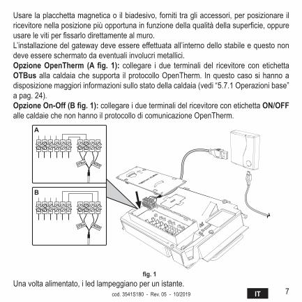
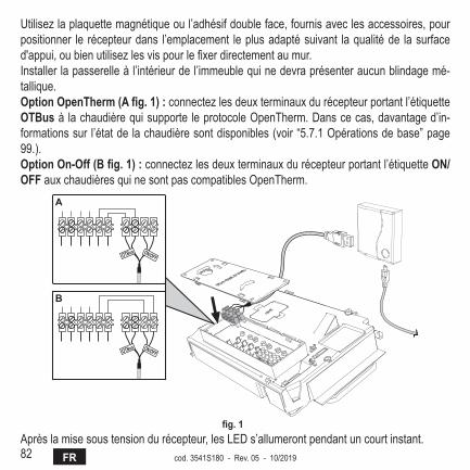
Usare la placchetta magnetica o il biadesivo, forniti tra gli accessori, per posizionare il ricevitorenellaposizionepiùopportunainfunzionedellaqualitàdellasuperficie,oppureusarelevitiperfissarlodirettamentealmuro.L’installazione del gateway deve essere effettuata all’interno dello stabile e questo non deve essere schermato da eventuali involucri metallici.Opzione OpenTherm (A fig. 1): collegare i due terminali del ricevitore con etichetta otBus alla caldaia che supporta il protocollo OpenTherm. In questo caso si hanno a disposizione maggiori informazioni sullo stato della caldaia (vedi “5.7.1 Operazioni base” a pag. 24).Opzione On-Off (B fig. 1): collegare i due terminali del ricevitore con etichetta oN/oFF alle caldaie che non hanno il protocollo di comunicazione OpenTherm.
����� ������
����� ������
�
�
fig. 1 Una volta alimentato, i led lampeggiano per un istante.
8 IT cod. 3541S180 - Rev. 05 - 10/2019
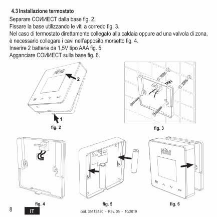
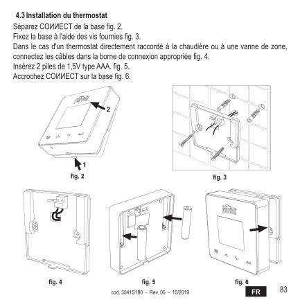
4.3 Installazione termostatoSeparareCOИИECTdallabasefig.2.Fissarelabaseutilizzandolevitiacorredofig.3.Nelcasoditermostatodirettamentecollegatoallacaldaiaoppureadunavalvoladizona,ènecessariocollegareicavinell’appositomorsettofig.4.Inserire2batterieda1,5VtipoAAAfig.5.AgganciareCOИИECTsullabasefig.6.
�
�
fig. 2 fig. 3
fig. 4 fig. 5 fig. 6

9ITcod. 3541S180 - Rev. 05 - 10/2019
4.4 montaggio supporto termostato
7
4.3 Installazione termostatoInserire 2 batterie da 1,5V tipo AAA.4.4 Montaggio supporto termostato
� �
� �
fig. 2 - fig. 7 - Supporto termostato
10 IT cod. 3541S180 - Rev. 05 - 10/2019
5. PEr utENtE FINalE
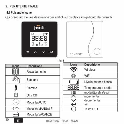
5.1 Pulsanti e IconeQuidiseguitoc’èunadescrizionedeisimbolisuldisplayeilsignificatodeipulsanti.
fig. 8
Icona descrizioneRiscaldamento
Sanitario
Fiamma
On / Off
Modalità AUTO
ModalitàMANUALEModalitàVACANZE
Icona descrizioneWireless
WiFi
Livello batteria basso
Temperatura e orariomodalità/salva/esciincrementadecrementasetTastoLED
11ITcod. 3541S180 - Rev. 05 - 10/2019
Batteria:Quandoillivellodellabatteriaèinsufficiente,siattival’iconasulloschermo.Fiamma
» Termostato collegato a una caldaia on-off, l’icona indica lo stato della richiesta. » Termostato collegato a una caldaia OpenTherm, l’icona indica lo stato del bruciatore.
Note: alla prima accensione il termostato si configura in automatico nella modalità collegamento a filo On-Off.Quando il termostato e il ricevitore Wifi sono collegati alla rete wireless, il termostato commuta automaticamente in modalità RF On-Off.Quando il ricevitore Wifi è collegato a una caldaia OpenTherm, il termostato com-muta automaticamente nella modalità RF OpenTherm.Se il termostato si è configurato come RF (on-off oppure OpenTherm) non commuta automaticamente in modalità filo on-off. Questo può essere fatto solo togliendo e rimettendo le pile.
Sanitario: in modalità manuale o automatico, l’icona sta ad indicare che il sanitario è attivo.
Note: l’icona è presente solo nel caso di collegamento RF con caldaie OpenTherm.riscaldamento: l’icona sta ad indicare che il riscaldamento è attivo.
Note: l’icona è presente solo nel caso di collegamento RF con caldaie OpenTherm.temperatura: viene visualizzata la temperatura ambiente o gli errori:
E82: errore di comunicazione RFE83: errore di comunicazione OpenTherm
12 IT cod. 3541S180 - Rev. 05 - 10/2019
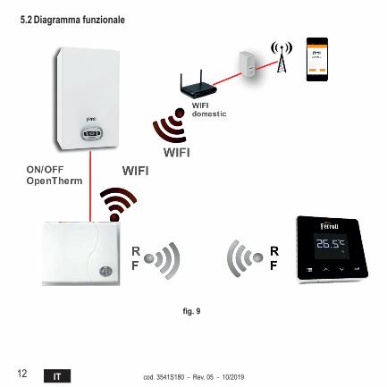
5.2 diagramma funzionale
fig. 9
13ITcod. 3541S180 - Rev. 05 - 10/2019
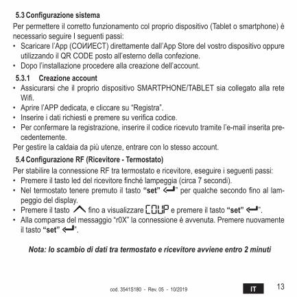
5.3 Configurazione sistemaPer permettere il corretto funzionamento col proprio dispositivo (Tablet o smartphone) è necessario seguire I seguenti passi:• Scaricarel’App(COИИECT)direttamentedall’AppStoredelvostrodispositivooppureutilizzandoilQRCODEpostoall’esternodellaconfezione.
• Dopo l’installazione procedere alla creazione dell’account.5.3.1 Creazione account• Assicurarsiche ilpropriodispositivoSMARTPHONE/TABLETsiacollegatoalla reteWifi.
• Aprire l’APP dedicata, e cliccare su “Registra”.• Inserireidatirichiestiepremeresuverificacodice.• Per confermare la registrazione, inserire il codice ricevuto tramite l’e-mail inserita pre-
cedentemente.Per gestire la caldaia da più utenze, entrare con lo stesso account.5.4 Configurazione RF (Ricevitore - Termostato)
Per stabilire la connessione RF tra termostato e ricevitore, eseguire i seguenti passi:• Premereiltastoleddelricevitorefinchélampeggia(circa7secondi).• Nel termostatotenerepremuto il tasto“set” ”perqualchesecondofinoal lam-
peggio del display.• Premere il tasto finoavisualizzare e premere il tasto “set” ”.• Alla comparsa del messaggio “r0X” la connessione è avvenuta. Premere nuovamente
il tasto “set” ”.
Nota: lo scambio di dati tra termostato e ricevitore avviene entro 2 minuti
14 IT cod. 3541S180 - Rev. 05 - 10/2019
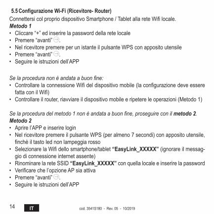
5.5 Configurazione Wi-Fi (Ricevitore- Router)ConnettersicolpropriodispositivoSmartphone/TabletallareteWifilocale.Metodo 1• Cliccare “+” ed inserire la password della rete locale• Premere “avanti” .• NelricevitorepremereperunistanteilpulsanteWPSconappositoutensile• Premere “avanti” .• Seguire le istruzioni dell’APP
Se la procedura non è andata a buon fine:• ControllarelaconnessioneWifideldispositivomobile(laconfigurazionedeveesserefattaconilWifi)
• Controllare il router, riavviare il dispositivo mobile e ripetere le operazioni (Metodo 1)
Se la procedura del metodo 1 non è andata a buon fine, proseguire con il metodo 2.Metodo 2• Aprire l’APP e inserire login• NelricevitorepremereilpulsanteWPS(peralmeno7secondi)conappositoutensile,finchèiltastolednonlampeggiarosso
• SelezionarelaWifidellosmartphone/tablet“Easylink_XXXXX” (ignorare il messag-gio di connessione internet assente)
• Rinominare la rete SSID “Easylink_XXXXX” con quella locale e inserire la password• Verificarechel’opzioneAPsiaattiva• Premere “avanti” .• Seguire le istruzioni dell’APP
15ITcod. 3541S180 - Rev. 05 - 10/2019
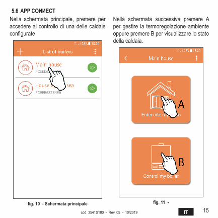
5.6 APP COИИECTNella schermata principale, premere peraccedere al controllo di una delle caldaie configurate
fig. 10 - Schermata principale
Nella schermata successiva premere Aper gestire la termoregolazione ambiente oppure premere B per visualizzare lo stato della caldaia.
fig. 11 -
16 IT cod. 3541S180 - Rev. 05 - 10/2019
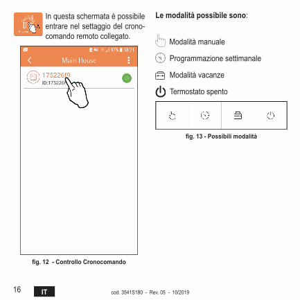
In questa schermata è possibile entrare nel settaggio del crono-comando remoto collegato.
fig. 12 - Controllo Cronocomando
le modalità possibile sono:
Modalità manuale
Programmazione settimanale
Modalità vacanze
Termostato spento
fig. 13 - Possibili modalità

17ITcod. 3541S180 - Rev. 05 - 10/2019
In questa schermata è possibile visualizzare lo stato della caldaia se questa è collegata tramite protocollo OpenTherm.Se la caldaia è collegata ad un termostato ambiente, nessuna informazione viene visualizzata.
fig. 14 - Con opentherm
fig. 15 Con termostato ambiente
18 IT cod. 3541S180 - Rev. 05 - 10/2019
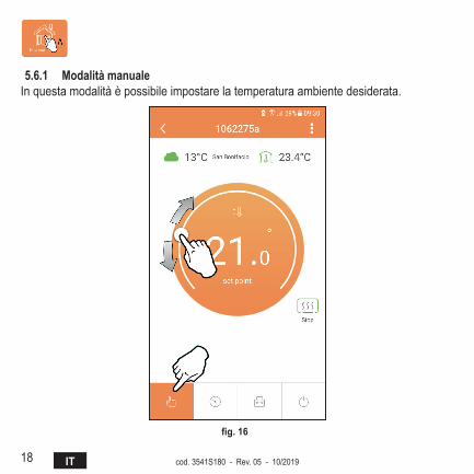
5.6.1 modalità manualeIn questa modalità è possibile impostare la temperatura ambiente desiderata.
fig. 16
19ITcod. 3541S180 - Rev. 05 - 10/2019
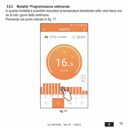
5.6.2 modalità “Programmazione settimanaleIn questa modalità è possibile impostare la temperatura desiderata nelle varie fasce ora-rie di tutti i giorni della settimana.Premendonelpuntoindicatoinfig.17.
fig. 17
20 IT cod. 3541S180 - Rev. 05 - 10/2019
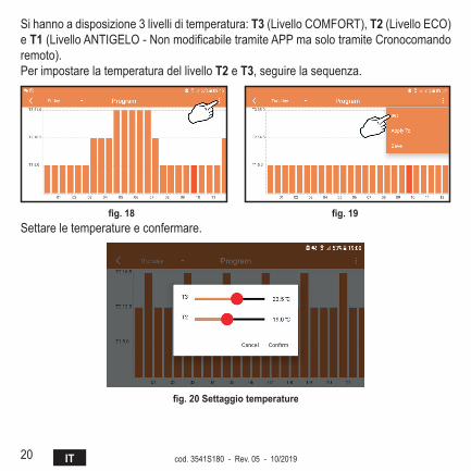
Si hanno a disposizione 3 livelli di temperatura: t3 (Livello COMFORT), t2(LivelloECO)e t1(LivelloANTIGELO-NonmodificabiletramiteAPPmasolotramiteCronocomandoremoto).Per impostare la temperatura del livello t2 e t3, seguire la sequenza.
fig. 18 fig. 19 Settare le temperature e confermare.
fig. 20 Settaggio temperature
21ITcod. 3541S180 - Rev. 05 - 10/2019
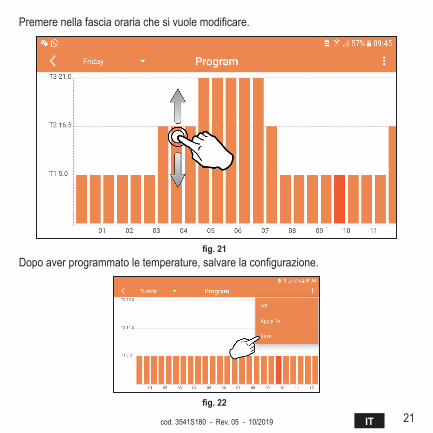
Premerenellafasciaorariachesivuolemodificare.
fig. 21 Dopoaverprogrammatoletemperature,salvarelaconfigurazione.
fig. 22
22 IT cod. 3541S180 - Rev. 05 - 10/2019
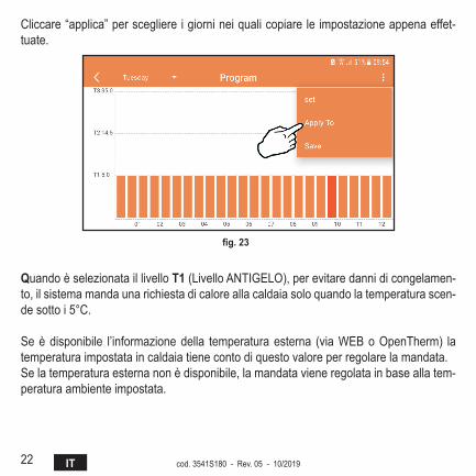
Cliccare “applica” per scegliere i giorni nei quali copiare le impostazione appena effet-tuate.
fig. 23
Quando è selezionata il livello t1(LivelloANTIGELO),perevitaredannidicongelamen-to, il sistema manda una richiesta di calore alla caldaia solo quando la temperatura scen-de sotto i 5°C.
Seèdisponibile l’informazionedella temperaturaesterna (viaWEBoOpenTherm) latemperatura impostata in caldaia tiene conto di questo valore per regolare la mandata.Se la temperatura esterna non è disponibile, la mandata viene regolata in base alla tem-peratura ambiente impostata.

23ITcod. 3541S180 - Rev. 05 - 10/2019
5.6.3 modalità vacanzeIn questa modalità la caldaia viene spenta e verrà riattivata nel caso in cui la tempe-ratura scenda sotto i 5°C.Premendo sull’icona impostazione , si potràimpostareladatadifinevacanza.
fig. 24
5.6.4 modalità termostato spentoIn questa modalità la caldaia viene spenta e verrà riattivata nel caso in cui la tempe-ratura scenda sotto i 5°C.
fig. 25
24 IT cod. 3541S180 - Rev. 05 - 10/2019
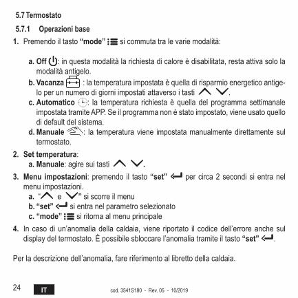
5.7 termostato5.7.1 operazioni base
1. Premendo il tasto “mode” si commuta tra le varie modalità:
a. off : in questa modalità la richiesta di calore è disabilitata, resta attiva solo la modalità antigelo.
b. Vacanza : la temperatura impostata è quella di risparmio energetico antige-lo per un numero di giorni impostati attaverso i tasti .
c. automatico : la temperatura richiesta è quella del programma settimanale impostata tramite APP. Se il programma non è stato impostato, viene usato quello di default del sistema.
d. manuale : la temperatura viene impostata manualmente direttamente sul termostato.
2. Set temperatura:a. manuale: agire sui tasti .
3. menu impostazioni: premendo il tasto “set” per circa 2 secondi si entra nel menu impostazioni.
a. “ e ” si scorre il menub. “set” si entra nel parametro selezionatoc. “mode” si ritorna al menu principale
4. In caso di un’anomalia della caldaia, viene riportato il codice dell’errore anche sul display del termostato. È possibile sbloccare l’anomalia tramite il tasto “set” .
Per la descrizione dell’anomalia, fare riferimento al libretto della caldaia.
25ITcod. 3541S180 - Rev. 05 - 10/2019
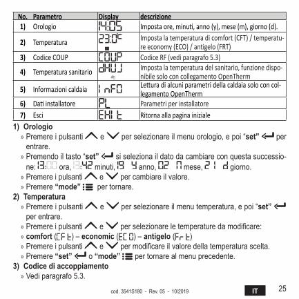
No. Parametro Display descrizione1) Orologio Imposta ore, minuti, anno (y), mese (m), giorno (d).
2) Temperatura Imposta la temperatura di comfort (CFT) / temperatu-re economy (ECO) / antigelo (FRT)
3) Codice COUP Codice RF (vedi paragrafo 5.3)
4) Temperatura sanitario Imposta la temperatura del sanitario, funzione dispo-nibile solo con collegamento OpenTherm
5) Informazioni caldaia Lettura di alcuni parametri della caldaia solo con col-legamento OpenTherm
6) Dati installatore Parametri per installatore7) Esci Ritorna alla pagina iniziale
1) orologio » Premere i pulsanti e per selezionare il menu orologio, e poi “set” per entrare.
» Premendo il tasto “set” si seleziona il dato da cambiare con questa successio-ne: ora, minuti, anno, mese, giorno.
» Premere i pulsanti e per cambiare il valore. » Premere “mode” per tornare.
2) temperatura » Premere i pulsanti e per selezionare il menu temperatura, e poi “set” per entrare.
» Premere i pulsanti e perselezionareletemperaturedamodificare: » comfort ( ) – economic ( ) – antigelo ( ) » Premere i pulsanti e permodificareilvaloredellatemperaturascelta. » Premere “set” o “mode” per tornare al menu precedente.
3) Codice di accoppiamento » Vedi paragrafo 5.3.
26 IT cod. 3541S180 - Rev. 05 - 10/2019
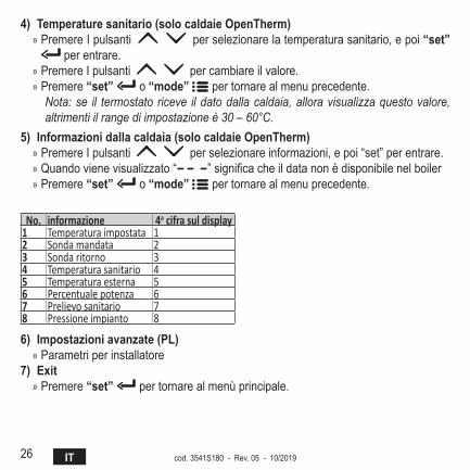
4) Temperature sanitario (solo caldaie OpenTherm) » Premere I pulsanti per selezionare la temperatura sanitario, e poi “set”
per entrare. » Premere I pulsanti per cambiare il valore. » Premere “set” o “mode” per tornare al menu precedente.
Nota: se il termostato riceve il dato dalla caldaia, allora visualizza questo valore, altrimenti il range di impostazione è 30 – 60°C.
5) Informazioni dalla caldaia (solo caldaie OpenTherm) » Premere I pulsanti per selezionare informazioni, e poi “set” per entrare. » Quando viene visualizzato “ ”significacheildatanonèdisponibilenelboiler » Premere “set” o “mode” per tornare al menu precedente.
No. informazione 4a cifra sul display1 Temperatura impostata 12 Sonda mandata 23 Sonda ritorno 34 Temperatura sanitario 45 Temperatura esterna 56 Percentuale potenza 67 Prelievo sanitario 78 Pressione impianto 8
6) Impostazioni avanzate (PL) » Parametri per installatore
7) Exit » Premere “set” per tornare al menù principale.
27ITcod. 3541S180 - Rev. 05 - 10/2019
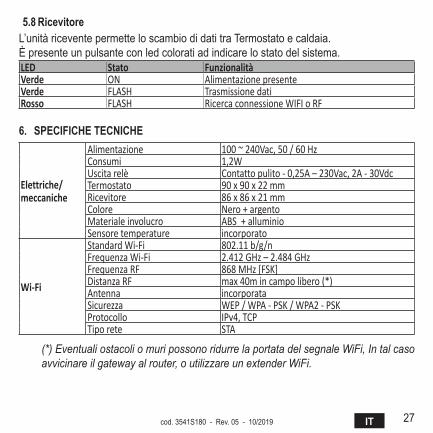
5.8 ricevitoreL’unità ricevente permette lo scambio di dati tra Termostato e caldaia.È presente un pulsante con led colorati ad indicare lo stato del sistema.LED Stato FunzionalitàVerde ON Alimentazione presenteVerde FLASH Trasmissione datiRosso FLASH Ricerca connessione WIFI o RF
6. SPECIFIChE tECNIChE
Elettriche/meccaniche
Alimentazione 100 ~ 240Vac, 50 / 60 HzConsumi 1,2WUscita relè Contatto pulito - 0,25A – 230Vac, 2A - 30VdcTermostato 90 x 90 x 22 mmRicevitore 86 x 86 x 21 mmColore Nero + argentoMateriale involucro ABS + alluminioSensore temperature incorporato
Wi-Fi
Standard Wi-Fi 802.11 b/g/nFrequenza Wi-Fi 2.412 GHz – 2.484 GHzFrequenza RF 868 MHz [FSK]Distanza RF max 40m in campo libero (*) Antenna incorporataSicurezza WEP / WPA - PSK / WPA2 - PSKProtocollo IPv4, TCPTipo rete STA
(*) Eventuali ostacoli o muri possono ridurre la portata del segnale WiFi, In tal caso avvicinare il gateway al router, o utilizzare un extender WiFi.
28 EN cod. 3541S180 - Rev. 05 - 10/2019
1. Introduction .................................................................................................... 29
2. General safety rules ....................................................................................... 29
3. Control class according to ErP regulations ................................................ 29
4. For the installer .............................................................................................. 304.1 Contents ...................................................................................................... 304.2 Installing the receiver ................................................................................... 314.3 Thermostat installation................................................................................. 334.4 Thermostat support assembly ..................................................................... 345. For the end user ............................................................................................. 355.1 Buttons and Icons ........................................................................................ 355.2 Functional diagram ...................................................................................... 375.3 System configuration ................................................................................... 385.3.1 Creating the account ........................................................................... 385.4 RF configuration (Receiver - Thermostat) ................................................... 385.5 Wi-Fi configuration (Receiver-Router) ......................................................... 395.6 APP COИИECT ........................................................................................... 405.6.1 Manual mode ...................................................................................... 435.6.2 Weekly programming mode ................................................................ 445.6.3 Vacation mode .................................................................................... 485.6.4 Thermostat mode off ........................................................................... 485.7 Thermostat................................................................................................... 495.7.1 Basic operations .................................................................................. 495.8 Receiver....................................................................................................... 526. Technicalspecifications ................................................................................ 52
29ENcod. 3541S180 - Rev. 05 - 10/2019
1. InTrOduCTIOnDear customer, thank you for choosing the COИИECT smart thermostat.It will allow you to accurately control the room temperature and, thanks to Wi-Fi connec-tivity, can be controlled remotely via the dedicated APP.This manual is intended for installers and end users.The main component of the system is the programmable thermostat that can manage the time programs set by the APP, measure the zone temperature and send on/off com-mands to the remote control unit, connected directly to the boiler.
2. GEnEralsafETyrulEs• Read the instructions in this manual carefully• After installation, inform the user about the device’s functions, and giving the user this
booklet to be kept carefully as an integral part of the product and subsequently used for future reference
• Installation and maintenance must be carried out by qualified personnel, according to the rules in force and the manufacturer's instructions. Do not perform any operation on the sealed control parts.
• Remove the electrical power supply before cleaning.• Do not place the device near heat sources.• Keep out of the reach of children
3. COnTrOlClassaCCOrdInGTOErPrEGulaTIOnsWith reference to the applicable regulation (EU) No. 811/2013, the data shown in the table can be used to complete the labeling of heating units.Possible combinations with COИИECT, related configuration classes and energy contri-bution to the system.
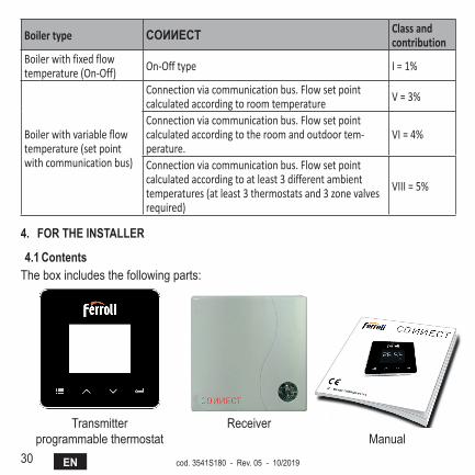
30 EN cod. 3541S180 - Rev. 05 - 10/2019
Boiler type COИИECT Class and contribution
Boiler with fixed flow temperature (On-Off) On-Off type I = 1%
Boiler with variable flow temperature (set point with communication bus)
Connection via communication bus. Flow set point calculated according to room temperature V = 3%
Connection via communication bus. Flow set point calculated according to the room and outdoor tem-perature.
VI = 4%
Connection via communication bus. Flow set point calculated according to at least 3 different ambient temperatures (at least 3 thermostats and 3 zone valves required)
VIII = 5%
4. fOrThEInsTallEr
4.1 ContentsThe box includes the following parts:
Transmitterprogrammable thermostat
ReceiverManual
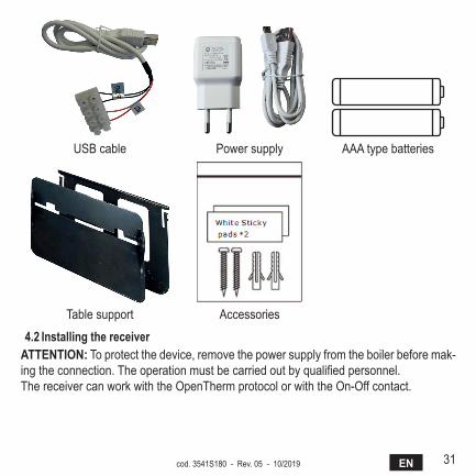
31ENcod. 3541S180 - Rev. 05 - 10/2019
USB cable Power supply AAA type batteries
Table support Accessories
4.2 Installing the receiveraTTEnTIOn: To protect the device, remove the power supply from the boiler before mak-ing the connection. The operation must be carried out by qualified personnel.The receiver can work with the OpenTherm protocol or with the On-Off contact.
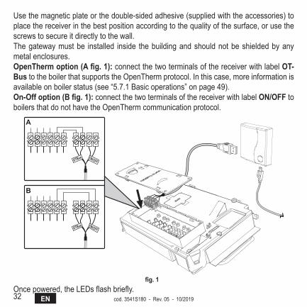
32 EN cod. 3541S180 - Rev. 05 - 10/2019
Use the magnetic plate or the double-sided adhesive (supplied with the accessories) to place the receiver in the best position according to the quality of the surface, or use the screws to secure it directly to the wall.The gateway must be installed inside the building and should not be shielded by any metal enclosures.OpenThermoption(afig.1): connect the two terminals of the receiver with label OT-Bus to the boiler that supports the OpenTherm protocol. In this case, more information is available on boiler status (see “5.7.1 Basic operations” on page 49).On-Offoption(Bfig.1): connect the two terminals of the receiver with label ON/OFF to boilers that do not have the OpenTherm communication protocol.
����� ������
����� ������
�
�
fig.1Once powered, the LEDs flash briefly.
33ENcod. 3541S180 - Rev. 05 - 10/2019
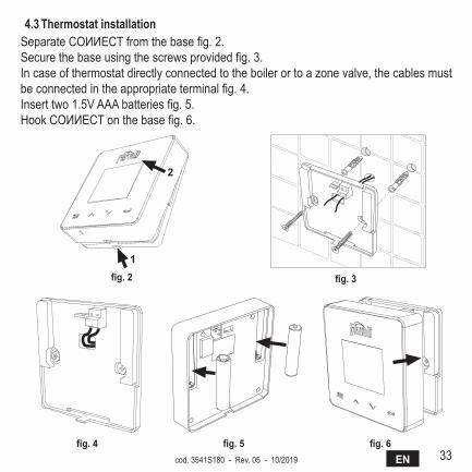
4.3 ThermostatinstallationSeparate COИИECT from the base fig. 2.Secure the base using the screws provided fig. 3.In case of thermostat directly connected to the boiler or to a zone valve, the cables must be connected in the appropriate terminal fig. 4.Insert two 1.5V AAA batteries fig. 5.Hook COИИECT on the base fig. 6.
�
�
fig.2 fig.3
fig.4 fig.5 fig.6
34 EN cod. 3541S180 - Rev. 05 - 10/2019
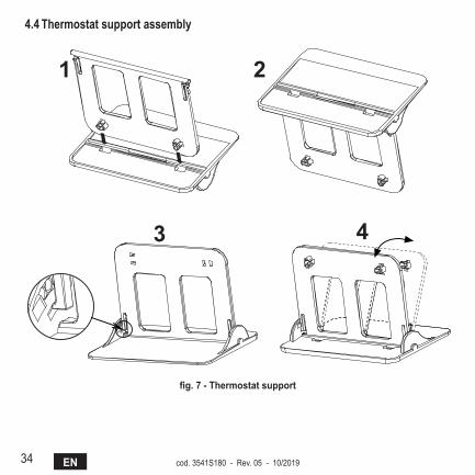
4.4 Thermostatsupportassembly
7
4.3 Installazione termostatoInserire 2 batterie da 1,5V tipo AAA.4.4 Montaggio supporto termostato
� �
� �
fig. 2 - fig.7-Thermostatsupport
35ENcod. 3541S180 - Rev. 05 - 10/2019
5. fOrThEEndusEr
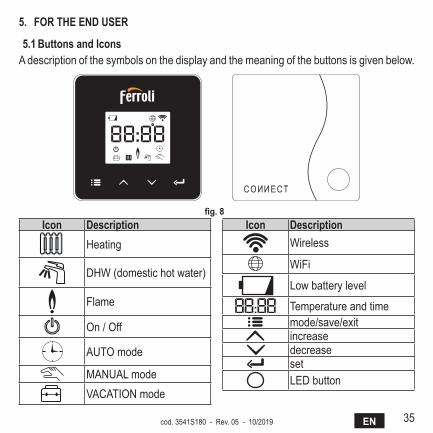
5.1 Buttons and IconsA description of the symbols on the display and the meaning of the buttons is given below.
fig.8Icon description
Heating
DHW (domestic hot water)
Flame
On / Off
AUTO mode
MANUAL modeVACATION mode
Icon descriptionWireless
WiFi
Low battery level
Temperature and timemode/save/exitincreasedecreasesetLED button
36 EN cod. 3541S180 - Rev. 05 - 10/2019
Battery: The icon on the screen is activated when the battery level is too low.flame
» Thermostat connected to an on-off boiler, the icon indicates request status. » Thermostat connected to an OpenTherm boiler, the icon indicates burner status.
Note: At first activation the thermostat is configured automatically in On-Off wire connection mode.When the thermostat and the WiFi receiver are connected to the wireless network, the thermostat automatically switches to RF On-Off.mode.When the WiFi receiver is connected to an OpenTherm boiler, the thermostat auto-matically switches to RF OpenTherm mode.If the thermostat has been configured as RF (on-off or OpenTherm) it does not automatically switch to on-off wire mode. This can only be done by removing and putting back the batteries.
dhW: in manual or automatic mode, the icon indicates that the appliance is active.Note: The icon is only present in the case of RF connection with OpenTherm boilers.
heating: the icon indicates that heating is active.Note: The icon is only present in the case of RF connection with OpenTherm boilers.
Temperature: the room temperature or errors are displayed:E82: RF communication errorE83: OpenTherm communication error
37ENcod. 3541S180 - Rev. 05 - 10/2019
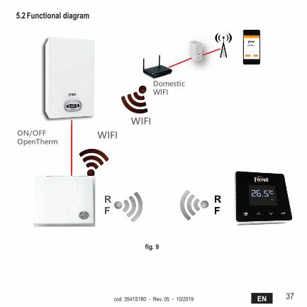
5.2 functionaldiagram
fig.9
38 EN cod. 3541S180 - Rev. 05 - 10/2019
5.3 systemconfigurationTo allow proper operation with your device (Tablet or smartphone), proceed as follows:• Download the App (COИИECT) directly from the App Store of your device or using
the QR CODE on the outside of the package.• After installation, create the account.5.3.1 Creating the account
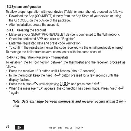
• Make sure your SMARTPHONE/TABLET device is connected to the Wifi network.• Open the dedicated APP, and click on “Register”.• Enter the requested data and press code verification.• To confirm the registration, enter the code received via the email previously entered.To manage the boiler from several users, enter with the same account.5.4 rfconfiguration(receiver-Thermostat)
To establish the RF connection between the thermostat and the receiver, proceed as follows:• Press the receiver LED button until it flashes (about 7 seconds).• In the thermostat keep the “set” ” button pressed for a few seconds until the
display flashes.• Press the button until displaying and press “set” ”.• When the message "r0X” appears, the connection has been made. Press “set”
” again.
Note: Data exchange between thermostat and receiver occurs within 2 min-utes
39ENcod. 3541S180 - Rev. 05 - 10/2019
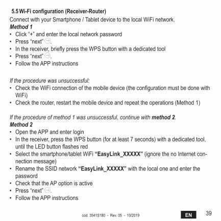
5.5 Wi-ficonfiguration(receiver-router)Connect with your Smartphone / Tablet device to the local WiFi network.Method 1• Click “+” and enter the local network password• Press “next” .• In the receiver, briefly press the WPS button with a dedicated tool• Press “next” .• Follow the APP instructions
If the procedure was unsuccessful:• Check the WiFi connection of the mobile device (the configuration must be done with
WiFi)• Check the router, restart the mobile device and repeat the operations (Method 1)
If the procedure of method 1 was unsuccessful, continue with method 2.Method 2• Open the APP and enter login• In the receiver, press the WPS button (for at least 7 seconds) with a dedicated tool,
until the LED button flashes red• Select the smartphone/tablet WiFi “Easylink_XXXXX” (ignore the no Internet con-
nection message)• Rename the SSID network “Easylink_XXXXX” with the local one and enter the
password• Check that the AP option is active• Press “next” .• Follow the APP instructions

40 EN cod. 3541S180 - Rev. 05 - 10/2019
5.6 aPPCOИИECTOn the main screen, press to access the control of one of the configured boilers
fig.10- Main screen
On the next screen, press A to manage the room temperature control or press B to dis-play boiler status.
fig.11-
41ENcod. 3541S180 - Rev. 05 - 10/2019
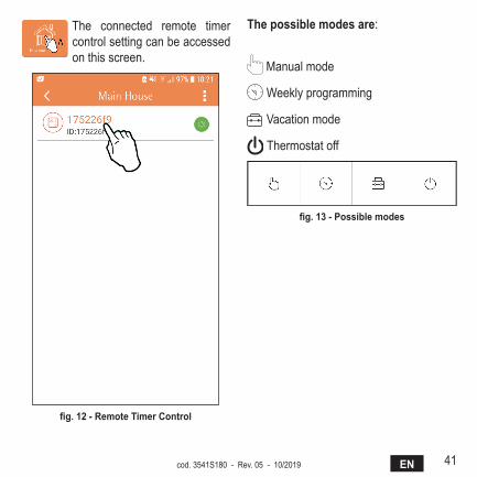
The connected remote timer control setting can be accessed on this screen.
fig.12-remoteTimerControl
Thepossiblemodesare:
Manual mode
Weekly programming
Vacation mode
Thermostat off
fig.13-Possiblemodes
42 EN cod. 3541S180 - Rev. 05 - 10/2019
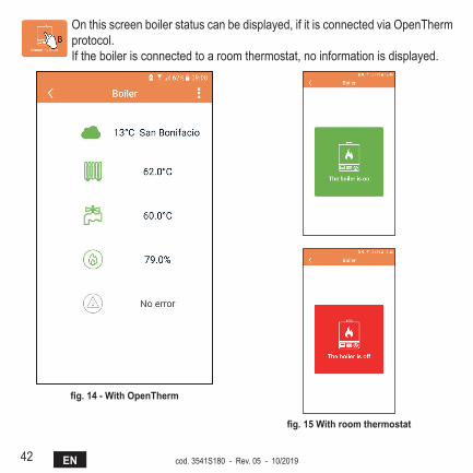
On this screen boiler status can be displayed, if it is connected via OpenTherm protocol.If the boiler is connected to a room thermostat, no information is displayed.
fig.14-WithOpenTherm
fig.15Withroomthermostat
43ENcod. 3541S180 - Rev. 05 - 10/2019
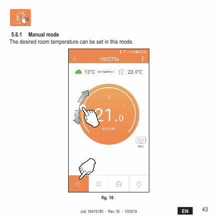
5.6.1 ManualmodeThe desired room temperature can be set in this mode.
fig.16
44 EN cod. 3541S180 - Rev. 05 - 10/2019
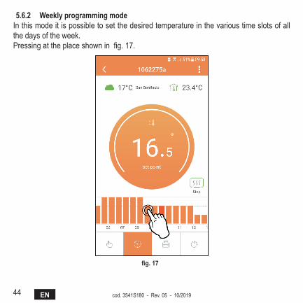
5.6.2 WeeklyprogrammingmodeIn this mode it is possible to set the desired temperature in the various time slots of all the days of the week.Pressing at the place shown in fig. 17.
fig.17
45ENcod. 3541S180 - Rev. 05 - 10/2019
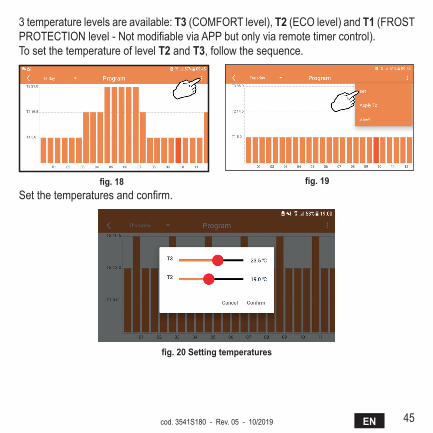
3 temperature levels are available: T3 (COMFORT level), T2 (ECO level) and T1 (FROST PROTECTION level - Not modifiable via APP but only via remote timer control).To set the temperature of level T2 and T3, follow the sequence.
fig.18 fig.19Set the temperatures and confirm.
fig.20settingtemperatures

46 EN cod. 3541S180 - Rev. 05 - 10/2019
Press in the time slot to be changed.
fig.21After programming the temperatures, save the configuration.
fig.22
47ENcod. 3541S180 - Rev. 05 - 10/2019
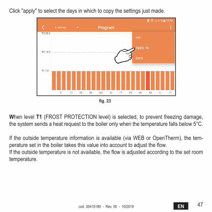
Click "apply" to select the days in which to copy the settings just made.
fig.23
When level T1 (FROST PROTECTION level) is selected, to prevent freezing damage, the system sends a heat request to the boiler only when the temperature falls below 5°C.
If the outside temperature information is available (via WEB or OpenTherm), the tem-perature set in the boiler takes this value into account to adjust the flow.If the outside temperature is not available, the flow is adjusted according to the set room temperature.
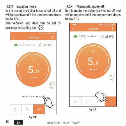
48 EN cod. 3541S180 - Rev. 05 - 10/2019
5.6.3 VacationmodeIn this mode the boiler is switched off and will be reactivated if the temperature drops below 5°C.The vacation end date can be set by pressing the setting icon .
fig.24
5.6.4 ThermostatmodeoffIn this mode the boiler is switched off and will be reactivated if the temperature drops below 5°C.
fig.25
49ENcod. 3541S180 - Rev. 05 - 10/2019
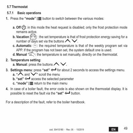
5.7Thermostat5.7.1 Basicoperations
1. Press the “mode” button to switch between the various modes:
a. Off : in this mode the heat request is disabled; only the frost protection mode remains active.
b.Vacation : the set temperature is that of frost protection energy saving for a number of days set via the buttons .
c. automatic : the required temperature is that of the weekly program set via APP. If the program has not been set, the system default one is used.
d. Manual : the temperature is set manually, directly on the thermostat.2. Temperaturesetting:
a. Manual: press the buttons .3. settingsmenu: press “set” for about 2 seconds to access the settings menu.
a. “ and ” scroll the menub.“set” access the selected parameterc. “mode” return to the main menu
4. In case of a boiler fault, the error code is also shown on the thermostat display. It is possible to reset the fault via the “set” button.
For a description of the fault, refer to the boiler handbook.
50 EN cod. 3541S180 - Rev. 05 - 10/2019
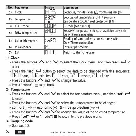
No. Parameter Display description1) Clock Set hours, minutes, year (y), month (m), day (d).
2) Temperature Set comfort temperature (CFT) / economy temperature (ECO) / frost protection (FRT)
3) COUP code RF code (see par. 5.3)
4) DHW temperature Set DHW temperature, function available only with OpenTherm connection
5) Boiler information Reading of some boiler parameters only with OpenTherm connection
6) Installer data Installer parameters7) Exit Return to the home page
1)Clock » Press the buttons and to select the clock menu, and then “set” to enter.
» Press the “set” button to select the data to be changed with this sequence: hour, minutes, year, month, day.
» Press the buttons and to change the value. » Press “mode” to go back.
2)Temperature » Press the buttons and to select the temperature menu, and then “set” to enter.
» Press the buttons and to select the temperatures to be changed: » comfort ( ) – economic ( ) – frostprotection ( ) » Press the buttons and to change the value of the selected temperature. » Press “set” or “mode” to return to the previous menu.
3)Couplingcode » See par. 5.3.
51ENcod. 3541S180 - Rev. 05 - 10/2019
4)dhWtemperatures(OpenThermboilersonly) » Press the buttons to select the DHW temperature, and then “set” to enter.
» Press the buttons to change the value. » Press “set” or “mode” to return to the previous menu.
Note: If the thermostat receives the data from the boiler, then it displays this value, otherwise the setting range is 30 – 60°C.
5)Informationfromtheboiler(OpenThermboilersonly) » Press the buttons to select information, and then "set" to enter. » When “ ” is displayed, it means the data is not available in the boiler » Press “set” or “mode” to return to the previous menu.
No. information 4th digit on the display1 Set temperature 12 Flow probe 23 Return probe 34 DHW temperature 45 Outside temperature 56 Power percentage 67 DHW draw 78 System pressure 8
6)advancedsettings(Pl) » Installer parameters
7)Exit » Press “set” to return to the main menu.
52 EN cod. 3541S180 - Rev. 05 - 10/2019
5.8receiverThe receiver unit allows data exchange between the thermostat and the boiler.A button with coloured LEDs indicates system status.LED Status FunctionalityGreen ON Power ONGreen FLASHING Data transmissionRed FLASHING WIFI or RF connection search
6. TEChnICalsPECIfICaTIOns
Electrical/mechanical
Power supply 100 ~ 240Vac, 50 / 60 HzConsumption 1.2WRelay output Voltage-free - 0.25A – 230Vac, 2A - 30VdcThermostat 90 x 90 x 22Receiver 86 x 86 x 21Colour Black + silverCasing material ABS + aluminiumTemperature sensor built-in
Wi-Fi
Wi-Fi standard 802.11 b/g/nWi-Fi frequency 2.412 GHz – 2.484 GHzRF frequency 868 MHz [FSK]RF distance max 40m in free field (*) Antenna built-inSafety WEP / WPA - PSK / WPA2 - PSKProtocol IPv4, TCPNetwork type STA
(*) Any obstacles or walls can reduce the WiFi signal range. In this case, bring the gateway closer to the router, or use a WiFi extender.
53EScod. 3541S180 - Rev. 05 - 10/2019
1. Introducción ................................................................................................... 54
2. Normas generales de seguridad .................................................................. 54
3. Categoría de control según el reglamento ErP ........................................... 54
4. Para el instalador ........................................................................................... 554.1 Contenido .................................................................................................... 554.2 Instalación del receptor ............................................................................... 564.3 Instalación del termostato ............................................................................ 584.4 Montaje del soporte del termostato ............................................................. 595. Para el usuario ............................................................................................... 605.1 Botones e iconos ......................................................................................... 605.2 Diagrama de funcionamiento ....................................................................... 625.3 Configuración del sistema ........................................................................... 635.3.1 Creación de la cuenta ......................................................................... 635.4 Configuración de RF (Receptor - Termostato) ............................................. 635.5 Configuración Wi-Fi (Receptor- Router) ...................................................... 645.6 APLICACIÓN COИИECT ............................................................................ 655.6.1 Modo manual ...................................................................................... 685.6.2 Modo "Programación semanal" ........................................................... 695.6.3 Modo Vacaciones ................................................................................ 735.6.4 Modo Termostato apagado ................................................................. 735.7 Termostato ................................................................................................... 745.7.1 Operaciones básicas ........................................................................... 745.8 Receptor ...................................................................................................... 776. Características técnicas ................................................................................ 77
54 ES cod. 3541S180 - Rev. 05 - 10/2019
1. InTrOduCCIónEstimado cliente: gracias por adquirir un termostato Smart COИИECT.Este dispositivo le permitirá hacer un control preciso de la temperatura ambiente, incluso a distancia mediante una conexión wifi y la aplicación específica.Este manual está dedicado a los instaladores y usuarios.El elemento principal del sistema es el cronotermostato, que gestiona los programas horarios configurados con la App, mide la temperatura de zona y transmite los mandos de encendido y apagado a una centralita remota conectada directamente a la caldera.
2. nOrmas gEnEralEs dE sEgurIdad• Lea atentamente las instrucciones contenidas en este manual.• Una vez terminada la instalación, explique al usuario las funciones del dispositivo y
entréguele este manual, que deberá conservar con cuidado por ser parte integrante del producto y para futuras consultas.
• La instalación y el mantenimiento deben ser realizados por un técnico autorizado, en conformidad con las normas vigentes y las instrucciones del fabricante. No realice ninguna operación en los componentes de control precintados.
• Desconecte la alimentación eléctrica antes de limpiar el dispositivo.• No sitúe el dispositivo cerca de fuentes de calor.• No deje el dispositivo al alcance de los niños.
3. CaTEgOría dE COnTrOl sEgún El rEglamEnTO ErPCon referencia al Reglamento Delegado (UE) n.º 811/2013, los datos presentes en la tabla pueden emplearse para completar el etiquetado de aparatos de calefacción.Combinaciones posibles con COИИECT, clases de configuración respectivas y contribu-ción energética al sistema.
55EScod. 3541S180 - Rev. 05 - 10/2019
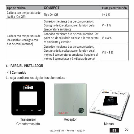
Tipo de caldera COИИECT Clase y contribuciónCaldera con temperatura de ida fija (On-Off) Tipo On-Off I = 1 %
Caldera con temperatura de ida variable (consigna con bus de comunicación)
Conexión mediante bus de comunicación. Consigna de ida calculada en función de la temperatura ambiente
V = 3 %
Conexión mediante bus de comunicación. Set point de ida calculado en base a la temperatu-ra ambiente y exterior.
VI = 4 %
Conexión mediante bus de comunicación. Consigna de ida calculada en función de al menos 3 temperaturas ambiente (requiere al menos 3 termostatos y 3 válvulas de zona)
VIII = 5 %
4. Para El InsTaladOr
4.1 ContenidoLa caja contiene los siguientes elementos:
TransmisorCronotermostato
ReceptorManual
56 ES cod. 3541S180 - Rev. 05 - 10/2019
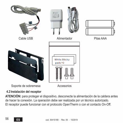
Cable USB Alimentador Pilas AAA
Soporte de sobremesa Accesorios
4.2 Instalación del receptoraTEnCIón: para proteger el dispositivo, desconecte la alimentación de la caldera antes de hacer la conexión. La operación debe ser realizada por un técnico autorizado.El receptor puede funcionar con el protocolo OpenTherm o con el contacto On-Off.
57EScod. 3541S180 - Rev. 05 - 10/2019
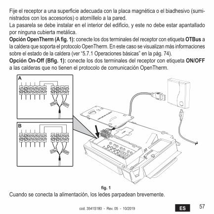
Fije el receptor a una superficie adecuada con la placa magnética o el biadhesivo (sumi-nistrados con los accesorios) o atorníllelo a la pared.La pasarela se debe instalar en el interior del edificio, y este no debe estar apantallado por ninguna cubierta metálica.Opción OpenTherm (a fig. 1): conecte los dos terminales del receptor con etiqueta OTBus a la caldera que soporta el protocolo OpenTherm. En este caso se visualizan más informaciones sobre el estado de la caldera (ver “5.7.1 Operaciones básicas” en la pág. 74).Opción On-Off (Bfig. 1): conecte los dos terminales del receptor con etiqueta ON/OFF a las calderas que no tienen el protocolo de comunicación OpenTherm.
����� ������
����� ������
�
�
fig. 1 Cuando se conecta la alimentación, los ledes parpadean brevemente.
58 ES cod. 3541S180 - Rev. 05 - 10/2019
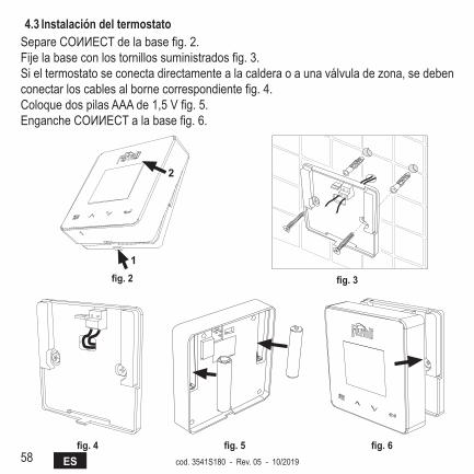
4.3 Instalación del termostatoSepare COИИECT de la base fig. 2.Fije la base con los tornillos suministrados fig. 3.Si el termostato se conecta directamente a la caldera o a una válvula de zona, se deben conectar los cables al borne correspondiente fig. 4.Coloque dos pilas AAA de 1,5 V fig. 5.Enganche COИИECT a la base fig. 6.
�
�
fig. 2 fig. 3
fig. 4 fig. 5 fig. 6
59EScod. 3541S180 - Rev. 05 - 10/2019
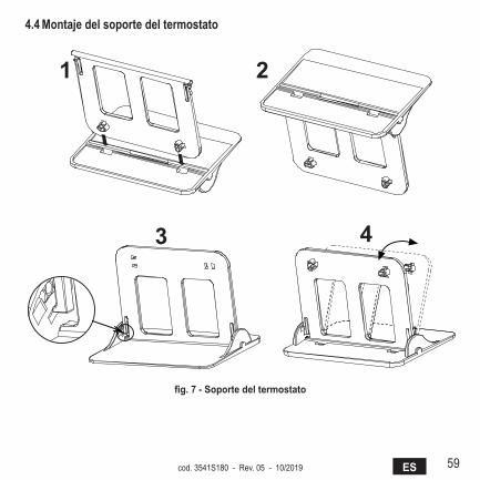
4.4 montaje del soporte del termostato
7
4.3 Installazione termostatoInserire 2 batterie da 1,5V tipo AAA.4.4 Montaggio supporto termostato
� �
� �
fig. 2 - fig. 7 - soporte del termostato
60 ES cod. 3541S180 - Rev. 05 - 10/2019
5. Para El usuarIO
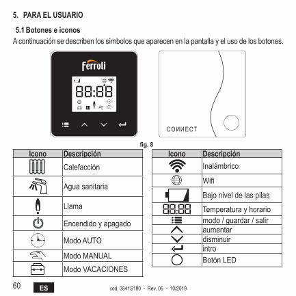
5.1 Botones e iconosA continuación se describen los símbolos que aparecen en la pantalla y el uso de los botones.
fig. 8 Icono descripción
Calefacción
Agua sanitaria
Llama
Encendido y apagado
Modo AUTO
Modo MANUALModo VACACIONES
Icono descripciónInalámbrico
Wifi
Bajo nivel de las pilas
Temperatura y horariomodo / guardar / saliraumentardisminuirintroBotón LED
61EScod. 3541S180 - Rev. 05 - 10/2019
Pilas: Cuando la carga de las pilas es insuficiente, aparece el icono en la pantalla.llama
» Termostato conectado a una caldera on-off; el icono indica el estado de la demanda. » Termostato conectado a una caldera OpenTherm; el icono indica el estado del que-mador.Nota: en el primer encendido, el termostato se configura automáticamente en el modo de conexión por cable On-Off.Cuando el termostato y el receptor wifi se conectan a la red inalámbrica, el termos-tato se conmuta automáticamente al modo RF On-Off.Cuando el receptor wifi se conecta a una caldera OpenTherm, el termostato se conmuta automáticamente al modo RF OpenTherm.Si el termostato se ha configurado como RF (On-Off u OpenTherm), no se conmuta automáticamente al modo cable on-off. Para obtener esta función, se deben quitar y volver a colocar las pilas.
aCs: tanto en modo manual como automático, el icono indica que está activada la pro-ducción de agua caliente sanitaria.
Nota: el icono está presente solo en caso de conexión RF con calderas Open-Therm.
Calefacción: el icono indica que está activada la calefacción.Nota: el icono está presente solo en caso de conexión RF con calderas Open-Therm.
Temperatura: se visualizan la temperatura ambiente o los errores:E82: error de comunicación RFE83: error de comunicación OpenTherm

62 ES cod. 3541S180 - Rev. 05 - 10/2019
5.2 diagrama de funcionamiento
fig. 9
63EScod. 3541S180 - Rev. 05 - 10/2019
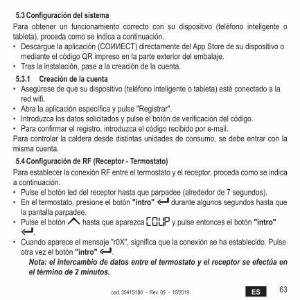
5.3 Configuración del sistemaPara obtener un funcionamiento correcto con su dispositivo (teléfono inteligente o tableta), proceda como se indica a continuación.• Descargue la aplicación (COИИECT) directamente del App Store de su dispositivo o
mediante el código QR impreso en la parte exterior del embalaje.• Tras la instalación, pase a la creación de la cuenta.5.3.1 Creación de la cuenta
• Asegúrese de que su dispositivo (teléfono inteligente o tableta) esté conectado a la red wifi.
• Abra la aplicación específica y pulse "Registrar".• Introduzca los datos solicitados y pulse el botón de verificación del código.• Para confirmar el registro, introduzca el código recibido por e-mail.Para controlar la caldera desde distintas unidades de consumo, se debe entrar con la misma cuenta.5.4 Configuración de rF (receptor - Termostato)
Para establecer la conexión RF entre el termostato y el receptor, proceda como se indica a continuación.• Pulse el botón led del receptor hasta que parpadee (alrededor de 7 segundos).• En el termostato, presione el botón "intro" durante algunos segundos hasta que
la pantalla parpadee.• Pulse el botón hasta que aparezca y pulse entonces el botón "intro"
.• Cuando aparece el mensaje "r0X", significa que la conexión se ha establecido. Pulse
otra vez el botón "intro" .Nota: el intercambio de datos entre el termostato y el receptor se efectúa en el término de 2 minutos.
64 ES cod. 3541S180 - Rev. 05 - 10/2019
5.5 Configuración Wi-Fi (receptor- router)Conectarse con el dispositivo Smartphone / Tablet propio a la red Wifi local.Método 1• Hacer clic en “+” e introducir la contraseña de la red local.• Pulse “continuar” .• En el receptor pulsar un instante la tecla WPS con la correspondiente herramienta.• Pulse “continuar” .• Seguir las instrucciones de la APP.
Si el procedimiento no termina correctamente:• Controlar la conexión Wifi del dispositivo móvil (la configuración debe efectuarse con
Wifi)• Controlar el router, reiniciar el dispositivo móvil y repetir las operaciones (Método 1)
Si el procedimiento del método 1 no resulta efectivo, continuar con el método 2.Método 2• Abrir la APP e introducir el login.• En el receptor pulsar la tecla WPS (al menos 7 segundos) con la correspondiente
herramienta hasta que la tecla led parpadee en rojo.• Seleccionar el Wifi del smartphone/tablet “Easylink_XXXXX” (ignorar el mensaje
de conexión Internet ausente)• Cambiar el nombre de la red SSID “Easylink_XXXXX” con la local e introducir la
contraseña• Comprobar que la opción APP esté activa.• Pulse “continuar” .• Seguir las instrucciones de la APP.
65EScod. 3541S180 - Rev. 05 - 10/2019
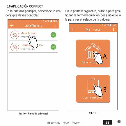
5.6 aPlICaCIón COИИECTEn la pantalla principal, seleccione la cal-dera que desee controlar.
fig. 10 - Pantalla principal
En la pantalla siguiente, pulse A para ges-tionar la termorregulación del ambiente o B para ver el estado de la caldera.
fig. 11 -
66 ES cod. 3541S180 - Rev. 05 - 10/2019
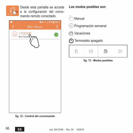
Desde esta pantalla se accede a la configuración del crono-mando remoto conectado.
fig. 12 - Control del cronomando
los modos posibles son:
Manual
Programación semanal
Vacaciones
Termostato apagado
fig. 13 - modos posibles
67EScod. 3541S180 - Rev. 05 - 10/2019
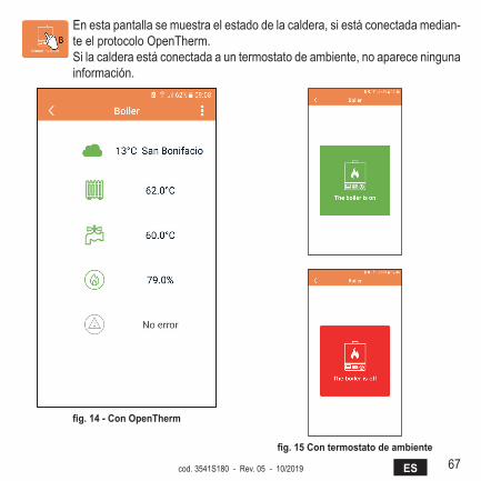
En esta pantalla se muestra el estado de la caldera, si está conectada median-te el protocolo OpenTherm.Si la caldera está conectada a un termostato de ambiente, no aparece ninguna información.
fig. 14 - Con OpenTherm
fig. 15 Con termostato de ambiente

68 ES cod. 3541S180 - Rev. 05 - 10/2019
5.6.1 modo manualEn esta modalidad es posible ajustar la temperatura ambiente deseada.
fig. 16

69EScod. 3541S180 - Rev. 05 - 10/2019
5.6.2 modo "Programación semanal"En esta modalidad es posible ajustar la temperatura deseada para las distintas franjas horarias de cada día de la semana.Pulse el punto indicado en la fig. 17.
fig. 17
70 ES cod. 3541S180 - Rev. 05 - 10/2019
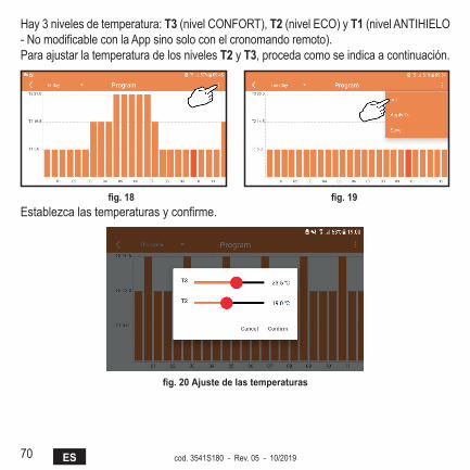
Hay 3 niveles de temperatura: T3 (nivel CONFORT), T2 (nivel ECO) y T1 (nivel ANTIHIELO - No modificable con la App sino solo con el cronomando remoto).Para ajustar la temperatura de los niveles T2 y T3, proceda como se indica a continuación.
fig. 18 fig. 19 Establezca las temperaturas y confirme.
fig. 20 ajuste de las temperaturas

71EScod. 3541S180 - Rev. 05 - 10/2019
Pulse y desplace la franja horaria que desee modificar.
fig. 21 Una vez programadas las temperaturas, guarde la configuración.
fig. 22
72 ES cod. 3541S180 - Rev. 05 - 10/2019
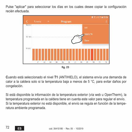
Pulse "aplicar" para seleccionar los días en los cuales desee copiar la configuración recién efectuada.
fig. 23
Cuando está seleccionado el nivel T1 (ANTIHIELO), el sistema envía una demanda de calor a la caldera solo si la temperatura baja a menos de 5 °C, para evitar daños por congelación.
Si está disponible la información de la temperatura exterior (vía web u OpenTherm), la temperatura programada en la caldera tiene en cuenta este valor para regular el envío.Si la temperatura exterior no está disponible, el envío se regula en función de la tempe-ratura ambiente programada.

73EScod. 3541S180 - Rev. 05 - 10/2019
5.6.3 modo VacacionesEn esta modalidad la caldera se apaga, y se vuelve a activar si la temperatura cae por debajo de 5 °C.Pulse el icono de configuración para progra-mar la fecha de terminación de las vacaciones.
fig. 24
5.6.4 modo Termostato apagadoEn esta modalidad la caldera se apaga, y se vuelve a activar si la temperatura cae por debajo de 5 °C.
fig. 25
74 ES cod. 3541S180 - Rev. 05 - 10/2019
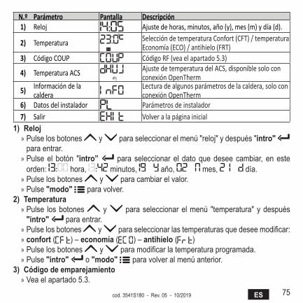
5.7 Termostato5.7.1 Operaciones básicas
1. Pulsando el botón "modo" se puede conmutar el funcionamiento entre las distintas opciones:
a. Off : en esta modalidad la demanda de calor está deshabilitada, permanece activada solo la función antihielo.
b. Vacaciones : está programada la temperatura de ahorro energético + anti-hielo por el número de días especificado con los botones .
c. automático : la consigna de temperatura es la del programa semanal, intro-ducida desde la aplicación. Si el programa no se ha configurado, se utilizan los valores de fábrica.
d. manual : la temperatura se ajusta a mano, directamente en el termostato.2. ajuste de la temperatura:
a. manual: utilice los botones .3. menú "configuración": pulse el botón "intro" durante 2 segundos para entrar
en el menú de configuración.a. " y " para desplazar el menúb. "intro" para acceder al parámetro seleccionadoc. "modo" para volver al menú principal
4. En caso de una anomalía de la caldera, el código del error aparece también en la pantalla del termostato. El estado de anomalía se puede desbloquear con el botón "intro" .
Para la descripción de la anomalía, consulte el manual de la caldera.
75EScod. 3541S180 - Rev. 05 - 10/2019
N.º Parámetro Pantalla Descripción1) Reloj Ajuste de horas, minutos, año (y), mes (m) y día (d).
2) Temperatura Selección de temperatura Confort (CFT) / temperatura Economía (ECO) / antihielo (FRT)
3) Código COUP Código RF (vea el apartado 5.3)
4) Temperatura ACS Ajuste de temperatura del ACS, disponible solo con conexión OpenTherm
5) Información de la caldera
Lectura de algunos parámetros de la caldera, solo con conexión OpenTherm
6) Datos del instalador Parámetros de instalador7) Salir Volver a la página inicial
1) reloj » Pulse los botones y para seleccionar el menú "reloj" y después "intro" para entrar.
» Pulse el botón "intro” para seleccionar el dato que desee cambiar, en este orden: hora, minutos, año, mes, día.
» Pulse los botones y para cambiar el valor. » Pulse "modo" para volver.
2) Temperatura » Pulse los botones y para seleccionar el menú "temperatura" y después "intro" para entrar.
» Pulse los botones y para seleccionar las temperaturas que desee modificar: » confort ( ) – economía ( ) – antihielo ( ) » Pulse los botones y para modificar la temperatura programada. » Pulse "intro" o "modo" para volver al menú anterior.
3) Código de emparejamiento » Vea el apartado 5.3.
76 ES cod. 3541S180 - Rev. 05 - 10/2019
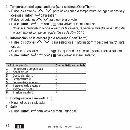
4) Temperatura del agua sanitaria (solo calderas OpenTherm) » Pulse los botones para seleccionar la temperatura del agua sanitaria y después "intro" para entrar.
» Pulse los botones para cambiar el valor. » Pulse "intro" o "modo" para volver al menú anterior.
Nota: si el termostato recibe el dato de la caldera, la pantalla muestra este valor; de lo contrario, el campo de regulación es de 30 – 60 °C.
5) Información de la caldera (solo calderas OpenTherm) » Pulse los botones para seleccionar "información" y después "intro" para entrar.
» Cuando se visualiza " " significa que el dato no está disponible en la caldera. » Pulse "intro" o "modo" para volver al menú anterior.
N.º información Cuarto dígito en pantalla1 Temperatura programada 12 Sonda de ida 23 Sonda de retorno 34 Temperatura ACS 45 Temperatura exterior 56 Porcentaje de potencia 67 Extracción de ACS 78 Presión instalación 8
6) Configuración avanzada (Pl) » Parámetros de instalador
7) salir » Pulse "intro" para volver al menú principal.
77EScod. 3541S180 - Rev. 05 - 10/2019
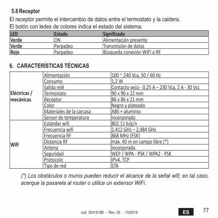
5.8 receptorEl receptor permite el intercambio de datos entre el termostato y la caldera.El botón con ledes de colores indica el estado del sistema.LED Estado SignificadoVerde ON Alimentación presenteVerde Parpadeo Transmisión de datosRojo Parpadeo Búsqueda conexión WIFI o RF
6. CaraCTErísTICas TéCnICas
Eléctricas / mecánicas
Alimentación 100 ~ 240 Vca, 50 / 60 HzConsumo 1,2 WSalida relé Contacto seco - 0,25 A – 230 Vca, 2 A - 30 VccTermostato 90 x 90 x 22 mmReceptor 86 x 86 x 21 mmColor Negro y plateadoMateriales de la carcasa ABS + aluminioSensor de temperatura incorporado
Wifi
Estándar wifi 802.11 b/g/nFrecuencia wifi 2,412 GHz – 2,484 GHzFrecuencia RF 868 MHz [FSK]Distancia RF máx. 40 m en campo libre (*) Antena incorporadaSeguridad WEP / WPA - PSK / WPA2 - PSKProtocolo IPv4, TCPTipo de red STA
(*) Los obstáculos o muros pueden reducir el alcance de la señal wifi; en tal caso, acerque la pasarela al router o utilice un extensor WiFi.
78 FR cod. 3541S180 - Rev. 05 - 10/2019
1. Introduction .................................................................................................... 79
2. Règles générales de sécurité ....................................................................... 79
3. Classe de contrôle selon le règlement de sécurité ERP ............................ 79
4. Pour l'installateur ........................................................................................... 804.1 Contenu ....................................................................................................... 804.2 Installation du récepteur .............................................................................. 814.3 Installation du thermostat ............................................................................ 834.4 Montage du support de thermostat .............................................................. 845. Pour l’utilisateur final .................................................................................... 855.1 Boutons et icônes ........................................................................................ 855.2 Diagramme fonctionnel ................................................................................ 875.3 Configuration du système ............................................................................ 885.3.1 Création de compte ............................................................................. 885.4 Configuration RF (Récepteur - Thermostat) ................................................ 885.5 Configuration Wi-Fi (Récepteur- Routeur) ................................................... 895.6 APP COИИECT ........................................................................................... 905.6.1 Mode manuel ...................................................................................... 935.6.2 Mode « Programmation hebdomadaire » ............................................ 945.6.3 Mode vacances ................................................................................... 985.6.4 Mode Thermostat éteint ...................................................................... 985.7 Thermostat................................................................................................... 995.7.1 Opérations de base ............................................................................. 995.8 Récepteur .................................................................................................. 1026. Caractéristiques techniques ....................................................................... 102
79FRcod. 3541S180 - Rev. 05 - 10/2019
1. InTrOduCTIOnChère cliente, cher client, merci d’avoir choisi le thermostat smart COИИECT.Ce thermostat vous permettra de contrôler avec précision la température ambiante et, grâce à la connectivité Wi-Fi, vous serez en mesure de le gérer à distance via l’application dédiée.Cette notice s'adresse aussi bien aux installateurs qu’aux utilisateurs finaux.L’élément principal du système est le chronothermostat qui peut non seulement gérer les pro-grammes horaires programmés via l’application, mais également mesurer la température de zone et envoyer les commandes d’allumage/d’extinction au module de commande (centrale) directement raccordé à la chaudière.2. règlEs généralEs dE séCurITé• Lire attentivement les instructions contenues dans la présente notice.• Après l’installation, informez l’utilisateur sur les fonctionnalités du dispositif et lui remettre
la présente notice. L’utilisateur devra, en outre, conserver avec soin cette notice pour toute consultation future. La présente notice fait partie intégrante du produit.
• L’installation et l’entretien devront être effectués par un professionnel qualifié conformé-ment aux textes réglementaires et règles de l'art en vigueur, ainsi qu’aux instructions four-nies par le constructeur. Ne pas intervenir sur les parties et/ou composants de commande ou contrôle scellés et/ou verrouillés.
• Couper l’alimentation électrique avant d’effectuer une quelconque opération de nettoyage.• Ne pas positionner le thermostat à proximité de sources de chaleur.• Tenir le thermostat hors de la portée des enfants.3. ClassE dE COnTrôlE sElOn lE règlEmEnT dE séCurITé ErPLes données indiquées dans le tableau peuvent être utilisées comme complément de l’étiquetage énergétique des dispositifs de chauffage, en référence au règlement délégué (UE) n° 811/2013.Combinaisons possibles avec COИИECT, classes de configuration correspondantes et contri-bution énergétique au système.
80 FR cod. 3541S180 - Rev. 05 - 10/2019
Type de chaudière COИИECT Classe et contribution
Chaudière avec température de départ fixe (On-Off) Type On-Off (« tout ou rien ») I = 1 %
Chaudière avec tempé-rature de départ variable (point de consigne par bus de communication)
Connexion par bus de communication. Point de consigne départ calculé en fonction de la température ambiante V = 3 %
Connexion par bus de communication. Point de consigne départ calculé en fonction de la température ambiante et extérieure.
VI = 4 %
Connexion par bus de communication. Point de consigne calculé en fonction d’au moins 3 températures ambiantes distinctes (installation nécessaire d’au moins 3 thermostats et 3 vannes de zone)
VIII = 5 %
4. POur l'InsTallaTEur4.1 Contenu
La boîte contient les éléments suivants :
Émetteurchronothermostat
RécepteurNotice
81FRcod. 3541S180 - Rev. 05 - 10/2019
Câble USB Fiche et câble d’alimentation Piles type AAA
Support de table Accessoires
4.2 Installation du récepteuraTTEnTIOn : coupez l’alimentation électrique de la chaudière avant d’effectuer le raccorde-ment, afin de protéger le dispositif. Cette opération doit être effectuée par un professionnel qualifié.Le récepteur peut communiquer avec le thermostat soit par protocole OpenTherm, soit par contact On-Off (« tout ou rien »).
82 FR cod. 3541S180 - Rev. 05 - 10/2019
Utilisez la plaquette magnétique ou l’adhésif double face, fournis avec les accessoires, pour positionner le récepteur dans l’emplacement le plus adapté suivant la qualité de la surface d'appui, ou bien utilisez les vis pour le fixer directement au mur.Installer la passerelle à l’intérieur de l’immeuble qui ne devra présenter aucun blindage mé-tallique.Option OpenTherm (a fig. 1) : connectez les deux terminaux du récepteur portant l’étiquette OTBus à la chaudière qui supporte le protocole OpenTherm. Dans ce cas, davantage d’in-formations sur l’état de la chaudière sont disponibles (voir “5.7.1 Opérations de base” page 99.).Option On-Off (B fig. 1) : connectez les deux terminaux du récepteur portant l’étiquette ON/OFF aux chaudières qui ne sont pas compatibles OpenTherm.
����� ������
����� ������
�
�
fig. 1 Après la mise sous tension du récepteur, les LED s’allumeront pendant un court instant.
83FRcod. 3541S180 - Rev. 05 - 10/2019
4.3 Installation du thermostatSéparez COИИECT de la base fig. 2.Fixez la base à l'aide des vis fournies fig. 3.Dans le cas d'un thermostat directement raccordé à la chaudière ou à une vanne de zone, connectez les câbles dans la borne de connexion appropriée fig. 4.Insérez 2 piles de 1,5V type AAA. fig. 5.Accrochez COИИECT sur la base fig. 6.
�
�
fig. 2 fig. 3
fig. 4 fig. 5 fig. 6

84 FR cod. 3541S180 - Rev. 05 - 10/2019
4.4 montage du support de thermostat
7
4.3 Installazione termostatoInserire 2 batterie da 1,5V tipo AAA.4.4 Montaggio supporto termostato
� �
� �
fig. 2 - fig. 7 - Support de thermostat
85FRcod. 3541S180 - Rev. 05 - 10/2019
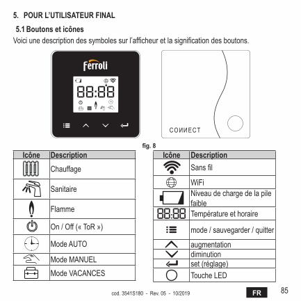
5. POur l’uTIlIsaTEur fInal5.1 Boutons et icônes
Voici une description des symboles sur l’afficheur et la signification des boutons.
fig. 8 Icône description
Chauffage
Sanitaire
Flamme
On / Off (« ToR »)
Mode AUTO
Mode MANUELMode VACANCES
Icône descriptionSans fil
WiFiNiveau de charge de la pile faibleTempérature et horaire
mode / sauvegarder / quitter
augmentationdiminutionset (réglage)Touche LED
86 FR cod. 3541S180 - Rev. 05 - 10/2019
Piles : quand le niveau de charge des piles est insuffisant, l’icône s’active sur l’afficheur.Flamme
» Thermostat connecté à une chaudière on-off (« tout ou rien ») : l’icône indique l’état de la demande.
» Thermostat connecté à une chaudière OpenTherm : l’icône indique l’état du brûleur.Remarques : le thermostat se configure automatiquement en mode connexion fi-laire On-Off au moment de son premier allumage.Quand le thermostat et le récepteur Wifi sont connectés au réseau sans fil, le fonc-tionnement du thermostat est automatiquement commuté en mode RF On-Off.Quand le récepteur Wifi est connecté à une chaudière OpenTherm, le fonctionne-ment du thermostat est automatiquement commuté en mode RF OpenTherm.Si le thermostat est configuré comme RF (on-off ou OpenTherm), son fonctionne-ment ne commutera pas automatiquement en mode filaire on-off. Ceci ne pourra être fait que si vous enlevez puis remettez en place les piles.
Sanitaire : en mode manuel ou automatique, l’icône indique l’activation du circuit sanitaire.Remarques : l’icône n'est présente que dans le cas de liaison RF avec les chau-dières OpenTherm.
Chauffage : l’icône indique l’activation du chauffage.Remarques : l’icône n'est présente que dans le cas de liaison RF avec les chau-dières OpenTherm.
Température : l’afficheur montre la température ambiante ou les erreurs ci-dessous :E82 : erreur de communication RFE83 : erreur de communication OpenTherm

87FRcod. 3541S180 - Rev. 05 - 10/2019
5.2 diagramme fonctionnel
fig. 9
88 FR cod. 3541S180 - Rev. 05 - 10/2019
5.3 Configuration du systèmePour permettre le fonctionnement correct du thermostat avec votre dispositif (tablette ou smartphone), suivez impérativement les étapes suivantes :• Téléchargez l’App (COИИECT) directement depuis l’App Store de votre dispositif ou via le
CODE QR figurant sur l’emballage.• Après l’installation, procédez à la création du compte.5.3.1 Création de compte
• Assurez-vous que votre dispositif SMARTPHONE/TABLETTE est connecté au réseau Wifi.• Ouvrez l’APP dédiée, puis cliquez sur « Enregister ».• Saisissez les données qui vous sont demandées et appuyez sur vérification du code.• Pour confirmer l'enregistrement, saisissez le code que vous avez reçu par mail à l’adresse
de courrier électronique saisie précédemment.Pour commander la chaudière à partir de plusieurs points, accéder à travers le même compte.5.4 Configuration rf (récepteur - Thermostat)
Pour établir la liaison radio RF entre le thermostat et le récepteur, suivez les étapes suivantes :• Appuyez sur la touche LED du récepteur jusqu’à obtenir son clignotement (environ 7
secondes).• Maintenez enfoncée la touche « set » pendant quelques secondes sur le thermostat,
jusqu’à obtention du clignotement de l'afficheur.• Appuyez sur la touche jusqu’à afficher et appuyez sur la touche « set » .• La liaison est établie dès que le message « r0X » s’affiche. Appuyez de nouveau sur la
touche « set » .
Remarque : l’échange des données entre thermostat et récepteur a lieu dans les 2 minutes qui suivent.
89FRcod. 3541S180 - Rev. 05 - 10/2019
5.5 Configuration Wi-fi (récepteur- routeur)Se connecter au réseau wi-fi local à travers le propre dispositif Smartphone / Tablette.Méthode 1• Cliquer sur « + » et saisir le mot de passe du réseau local• Appuyer sur « suivant » .• Appuyer un court instant sur le bouton WPS du récepteur à l’aide d’un outil approprié.• Appuyer sur « suivant » .• Suivre les instructions de l’appli
Si la procédure a échoué :• Vérifier la connexion wi-fi du dispositif mobile (procéder à la configuration en se connec-
tant au réseau wi-fi)• Vérifier le routeur, remettre le dispositif mobile en marche et répéter les opérations (Mé-
thode 1)
Si la procédure de la méthode 1 échoue, passer à la méthode 2.Méthode 2• Ouvrir l’appli et effectuer le login• Appuyer (au moins 7 secondes) sur le bouton WPS du récepteur à l’aide d’un outil appro-
prié, jusqu’à ce que la led rouge clignote• Sélectionner le réseau wi-fi du smartphone/de la tablette “EasyLink_XXXXX” (ignorer le
message de connexion Internet absente)• Renommer le réseau SSID “EasyLink_XXXXX” avec le nom du réseau local et saisir le
mot de passe• S’assurer que l’option AP est activée• Appuyer sur « suivant » .• Suivre les instructions de l’appli
90 FR cod. 3541S180 - Rev. 05 - 10/2019
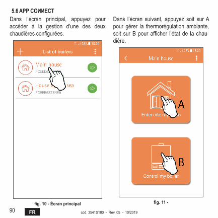
5.6 aPP COИИECTDans l’écran principal, appuyez pour accéder à la gestion d'une des deux chaudières configurées.
fig. 10 - Écran principal
Dans l’écran suivant, appuyez soit sur A pour gérer la thermorégulation ambiante, soit sur B pour afficher l’état de la chau-dière.
fig. 11 -
91FRcod. 3541S180 - Rev. 05 - 10/2019
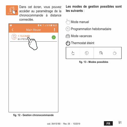
Dans cet écran, vous pouvez accéder au paramétrage de la chronocommande à distance connectée.
fig. 12 - Gestion chronocommande
Les modes de gestion possibles sont les suivants :
Mode manuel
Programmation hebdomadaire
Mode vacances
Thermostat éteint
fig. 13 - modes possibles
92 FR cod. 3541S180 - Rev. 05 - 10/2019
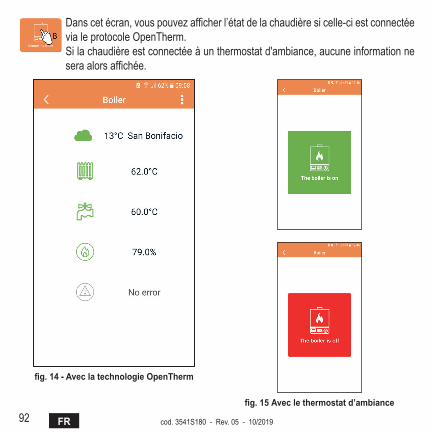
Dans cet écran, vous pouvez afficher l’état de la chaudière si celle-ci est connectée via le protocole OpenTherm.Si la chaudière est connectée à un thermostat d'ambiance, aucune information ne sera alors affichée.
fig. 14 - avec la technologie OpenTherm
fig. 15 Avec le thermostat d’ambiance

93FRcod. 3541S180 - Rev. 05 - 10/2019
5.6.1 mode manuelCe mode vous permet de programmer la température ambiante désirée.
fig. 16
94 FR cod. 3541S180 - Rev. 05 - 10/2019
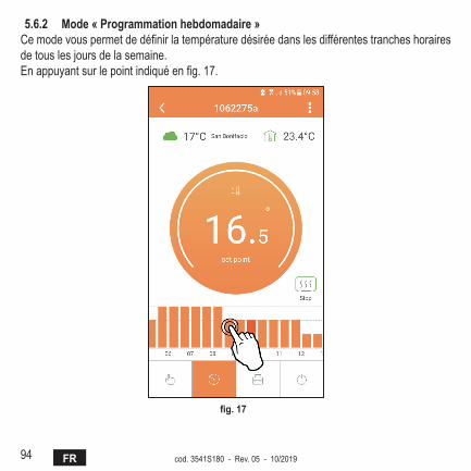
5.6.2 mode « Programmation hebdomadaire »Ce mode vous permet de définir la température désirée dans les différentes tranches horaires de tous les jours de la semaine.En appuyant sur le point indiqué en fig. 17.
fig. 17

95FRcod. 3541S180 - Rev. 05 - 10/2019
3 niveaux de température sont disponibles : T3 (Niveau CONFORT), T2 (Niveau ECO) et T1 (Niveau HORS GEL - Non modifiable via l’APP mais seulement par la chronocommande à distance).Pour programmer la température des niveaux T2 et T3, suivez la séquence.
fig. 18 fig. 19 Programmez les températures et confirmez.
fig. 20 Programmation des températures

96 FR cod. 3541S180 - Rev. 05 - 10/2019
Appuyez sur la tranche horaire que vous souhaitez modifier.
fig. 21 Sauvegardez la configuration après avoir programmé les températures.
fig. 22
97FRcod. 3541S180 - Rev. 05 - 10/2019
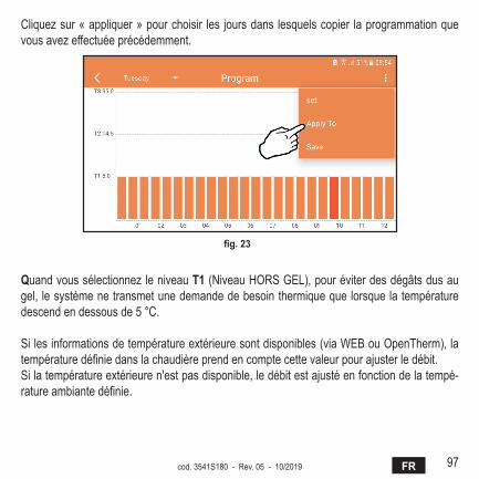
Cliquez sur « appliquer » pour choisir les jours dans lesquels copier la programmation que vous avez effectuée précédemment.
fig. 23
Quand vous sélectionnez le niveau T1 (Niveau HORS GEL), pour éviter des dégâts dus au gel, le système ne transmet une demande de besoin thermique que lorsque la température descend en dessous de 5 °C.
Si les informations de température extérieure sont disponibles (via WEB ou OpenTherm), la température définie dans la chaudière prend en compte cette valeur pour ajuster le débit.Si la température extérieure n'est pas disponible, le débit est ajusté en fonction de la tempé-rature ambiante définie.

98 FR cod. 3541S180 - Rev. 05 - 10/2019
5.6.3 mode vacancesDans ce mode, la chaudière est éteinte et n’est remise en marche que si la tempéra-ture descend en dessous de 5 °C.En appuyant sur l’icône configuration , vous pourrez définir la date de fin des vacances.
fig. 24
5.6.4 mode Thermostat éteintDans ce mode, la chaudière est éteinte et n’est remise en marche que si la tempéra-ture descend en dessous de 5 °C.
fig. 25
99FRcod. 3541S180 - Rev. 05 - 10/2019
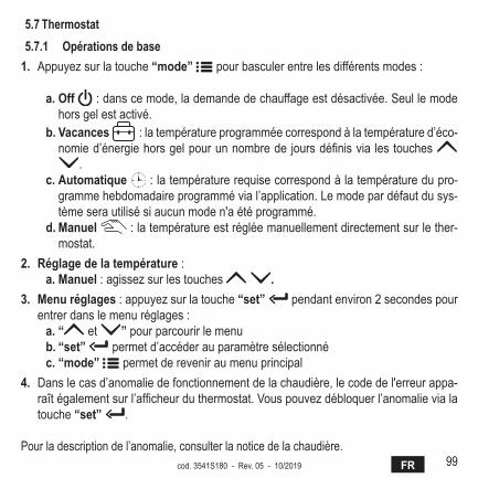
5.7 Thermostat5.7.1 Opérations de base
1. Appuyez sur la touche “mode” pour basculer entre les différents modes :
a. Off : dans ce mode, la demande de chauffage est désactivée. Seul le mode hors gel est activé.
b. Vacances : la température programmée correspond à la température d’éco-nomie d’énergie hors gel pour un nombre de jours définis via les touches
.c. Automatique : la température requise correspond à la température du pro-
gramme hebdomadaire programmé via l’application. Le mode par défaut du sys-tème sera utilisé si aucun mode n'a été programmé.
d. manuel : la température est réglée manuellement directement sur le ther-mostat.
2. Réglage de la température :a. manuel : agissez sur les touches .
3. menu réglages : appuyez sur la touche “set” pendant environ 2 secondes pour entrer dans le menu réglages :
a. “ et ” pour parcourir le menub. “set” permet d’accéder au paramètre sélectionnéc. “mode” permet de revenir au menu principal
4. Dans le cas d’anomalie de fonctionnement de la chaudière, le code de l'erreur appa-raît également sur l’afficheur du thermostat. Vous pouvez débloquer l’anomalie via la touche “set” .
Pour la description de l’anomalie, consulter la notice de la chaudière.
100 FR cod. 3541S180 - Rev. 05 - 10/2019
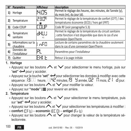
N° Paramètre Afficheur description
1) Horloge Permet le réglage des heures, des minutes, de l’année (y), du mois (m), du jour (d).
2) Température Permet le réglage de la température de confort (CFT) / des températures économie (ECO) / hors gel (FRT)
3) Code COUP Code RF (voir paragraphe 5.3)
4) Température sanitaire
Permet le réglage de la température du circuit sanitaire ; cette fonction n'est disponible que dans le cas d'une connexion OpenTherm
5) Informations sur la chaudière
Lecture de certains paramètres de la chaudière seulement dans le cas d'une connexion OpenTherm
6) Données de l’installateur Paramètres pour l’installateur
7) Quitter Retour à la page initiale1. Horloge
» Appuyez sur les boutons et pour sélectionner le menu horloge, puis sur “set” pour y accéder.
» Appuyez sur la touche “set” pour sélectionner les données à modifier avec cette séquence : heure, minutes, année, mois, jour.
» Appuyez sur les boutons et pour modifier la valeur. » Appuyez sur “mode” pour revenir en arrière.
2. Température » Appuyez sur les boutons et pour sélectionner le menu température, puis sur “set” pour y accéder.
» Appuyez sur les boutons et pour sélectionner les températures à modifier : » comfort ( ) – economic ( ) – antigel ( ) » Appuyez sur les boutons et pour changer la valeur de la température sé-lectionnée.
101FRcod. 3541S180 - Rev. 05 - 10/2019
» Appuyez sur “set” ou “mode” pour revenir au menu précédent.3. Code de couplage
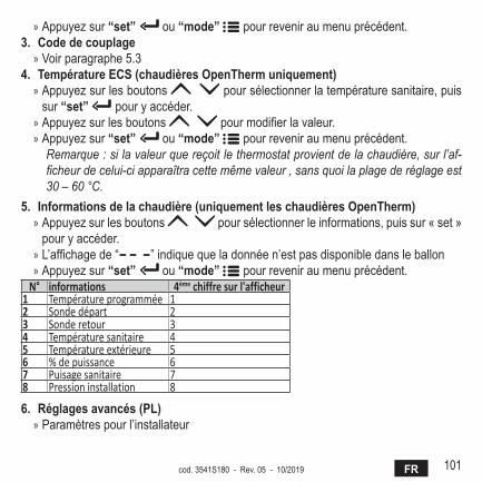
» Voir paragraphe 5.34. Température ECs (chaudières OpenTherm uniquement)
» Appuyez sur les boutons pour sélectionner la température sanitaire, puis sur “set” pour y accéder.
» Appuyez sur les boutons pour modifier la valeur. » Appuyez sur “set” ou “mode” pour revenir au menu précédent.
Remarque : si la valeur que reçoit le thermostat provient de la chaudière, sur l’af-ficheur de celui-ci apparaîtra cette même valeur , sans quoi la plage de réglage est 30 – 60 °C.
5. Informations de la chaudière (uniquement les chaudières OpenTherm) » Appuyez sur les boutons pour sélectionner le informations, puis sur « set » pour y accéder.
» L’affichage de “ ” indique que la donnée n’est pas disponible dans le ballon » Appuyez sur “set” ou “mode” pour revenir au menu précédent.
N° informations 4ème chiffre sur l'afficheur1 Température programmée 12 Sonde départ 23 Sonde retour 34 Température sanitaire 45 Température extérieure 56 % de puissance 67 Puisage sanitaire 78 Pression installation 8
6. réglages avancés (Pl) » Paramètres pour l’installateur
102 FR cod. 3541S180 - Rev. 05 - 10/2019
7. Exit » Appuyez sur “set” pour revenir au menu principal.
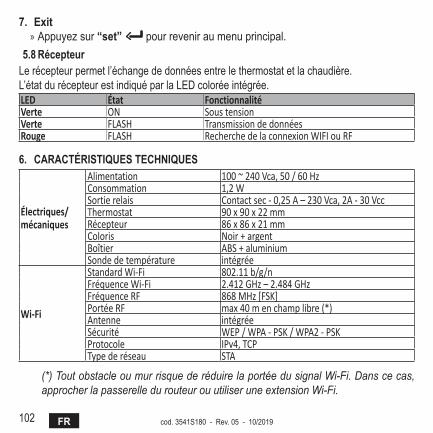
5.8 RécepteurLe récepteur permet l’échange de données entre le thermostat et la chaudière.L’état du récepteur est indiqué par la LED colorée intégrée.LED État FonctionnalitéVerte ON Sous tensionVerte FLASH Transmission de donnéesRouge FLASH Recherche de la connexion WIFI ou RF
6. CaraCTérIsTIquEs TEChnIquEs
Électriques/mécaniques
Alimentation 100 ~ 240 Vca, 50 / 60 HzConsommation 1,2 WSortie relais Contact sec - 0,25 A – 230 Vca, 2A - 30 VccThermostat 90 x 90 x 22 mmRécepteur 86 x 86 x 21 mmColoris Noir + argentBoîtier ABS + aluminiumSonde de température intégrée
Wi-Fi
Standard Wi-Fi 802.11 b/g/nFréquence Wi-Fi 2.412 GHz – 2.484 GHzFréquence RF 868 MHz [FSK]Portée RF max 40 m en champ libre (*) Antenne intégréeSécurité WEP / WPA - PSK / WPA2 - PSKProtocole IPv4, TCPType de réseau STA
(*) Tout obstacle ou mur risque de réduire la portée du signal Wi-Fi. Dans ce cas, approcher la passerelle du routeur ou utiliser une extension Wi-Fi.
103ROcod. 3541S180 - Rev. 05 - 10/2019
1. Prezentare ..................................................................................................... 104
2. Normegeneraledesiguranţă ..................................................................... 104
3. Clasa de control conform regulamentului ErP .......................................... 104
4. Pentru instalator .......................................................................................... 1054.1 Conţinut ..................................................................................................... 1054.2 Instalareareceptorului ............................................................................... 1064.3 Instalareatermostatului ............................................................................. 1084.4 Montareasuportuluitermostatului ............................................................. 1095. Pentru utilizatorul final ................................................................................ 1105.1 Butoaneşipictograme ................................................................................1105.2 Diagramăfuncţională ..................................................................................1125.3 Configurareasistemului ..............................................................................1135.3.1 Creareacontului .................................................................................1135.4 ConfigurareaRF(Receptor-Termostat) ....................................................1135.5 ConfigurareaWi-Fi(Receptor-Router)......................................................1145.6 APLICAŢIACOИИECT .............................................................................. 1155.6.1 Modulmanual .....................................................................................1185.6.2 Modul„Programaresăptămânală” .....................................................1195.6.3 Modulvacanţă ................................................................................... 1235.6.4 ModulTermostatoprit ........................................................................ 1235.7 Termostat ................................................................................................... 1245.7.1 Operaţiidebază ................................................................................ 1245.8 Receptor .................................................................................................... 1276. Specificaţiitehnice ...................................................................................... 127
104 RO cod. 3541S180 - Rev. 05 - 10/2019
1. PrEzENTarEStimateclient,vămulţumimcăaţialestermostatulinteligentCOИИECT.Acestavăvapermitesăcontrolaţicuprecizietemperaturaambiantăşi,datorităconecti-vităţiiWi-Fi,poateficontrolatdeladistanţăprinaplicaţiaspecială.Acestmanualestedestinatinstalatorilorşiutilizatorilorfinali.Elementulprincipalalsistemuluiestecronotermostatulcarepoategestionaprogrameleoraresetatedeaplicaţie,poatemăsuratemperaturazoneişipoatetrimitecomenziledepornire/oprirelaunitateadecomandădeladistanţă,conectatădirectlacentrală.
2. NOrmEgENEralEdESiguraNţă• Citiţicuatenţieinstrucţiuniledinacestmanual.• Dupăinstalare,informaţiutilizatorulînlegăturăcufuncţionareadispozitivuluişilăsaţi-iaceastăbroşură,carevatrebuisăfiepăstratăcugrijă,deoarececonstituieoparteintegrantăaprodusului,pentruaputeafifolosităpeviitorcareferinţă.
• Instalareaşiîntreţinereatrebuiesăfieefectuatedepersonalspecializatşicalificat,înconformitatecunormeleînvigoareşicuinstrucţiunileproducătorului.Nuefectuaţiniciooperaţiuneasuprapieselordecontrolsigilate.
• Deconectaţidelaalimentareacuelectricitateînaintedecurăţare.• Nuplasaţidispozitivulînapropiereasurselordecăldură.• Anuselăsalaîndemânacopiilor.
3. ClaSadECONTrOlCONfOrmrEgulamENTuluiErPÎnconformitatecuRegulamentuldelegat(UE)Nr.811/2013,dateleindicateîntabelpotfiutilizatecaocompletareaeticheteloraparatelordeîncălzire.Combinaţiileposibile cuCOИИECT,clasele corespunzătoaredeconfigurareşi contri-buţiaenergeticălasistem.
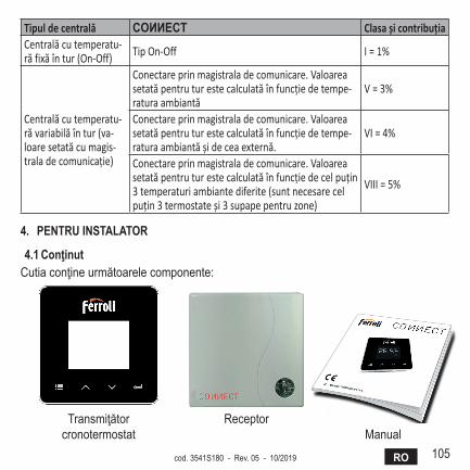
105ROcod. 3541S180 - Rev. 05 - 10/2019
Tipul de centrală COИИECT Clasa şi contribuţiaCentrală cu temperatu-ră fixă în tur (On-Off) Tip On-Off I = 1%
Centrală cu temperatu-ră variabilă în tur (va-loare setată cu magis-trala de comunicaţie)
Conectare prin magistrala de comunicare. Valoarea setată pentru tur este calculată în funcţie de tempe-ratura ambiantă
V = 3%
Conectare prin magistrala de comunicare. Valoarea setată pentru tur este calculată în funcţie de tempe-ratura ambiantă și de cea externă.
VI = 4%
Conectare prin magistrala de comunicare. Valoarea setată pentru tur este calculată în funcţie de cel puţin 3 temperaturi ambiante diferite (sunt necesare cel puţin 3 termostate și 3 supape pentru zone)
VIII = 5%
4. PENTruiNSTalaTOr
4.1 ConţinutCutiaconţineurmătoarelecomponente:
Transmiţătorcronotermostat
ReceptorManual
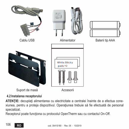
106 RO cod. 3541S180 - Rev. 05 - 10/2019
CabluUSB Alimentator BateriitipAAA
Suportdemasă Accesorii
4.2 instalareareceptoruluiaTENţiE:decuplaţialimentareacuelectricitateacentralei înaintedeaefectuacone-xiunea,pentruaprotejadispozitivul.Operaţiunea trebuiesăfieefectuatădepersonalspecializat.ReceptorulpoatefuncţionacuprotocolulOpenThermsaucucontactulOn-Off.
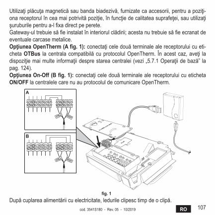
107ROcod. 3541S180 - Rev. 05 - 10/2019
Utilizaţiplăcuţamagneticăsaubandabiadezivă,furnizatecaaccesorii,pentruapoziţi-onareceptorulînceamaipotrivităpoziţie,înfuncţiedecalitateasuprafeţei,sauutilizaţişuruburilepentrua-lfixadirectpeperete.Gateway-ultrebuiesăfieinstalatîninteriorulclădirii;acestanutrebuiesăfieecranatdeeventualecarcasemetalice.OpţiuneaOpenTherm(afig.1):conectaţiceledouăterminalealereceptoruluicueti-chetaOTBus lacentralacompatibilăcuprotocolulOpenTherm. Înacestcaz,aveţi ladispoziţiemaimulte informaţiidesprestareacentralei(vezi„5.7.1Operaţiidebază” lapag.124).OpţiuneaOn-Off(Bfig.1):conectaţiceledouăterminalealereceptoruluicuetichetaON/OfflacentralelecarenuauprotocoluldecomunicareOpenTherm.
����� ������
����� ������
�
�
fig.1Dupăcuplareaalimentăriicuelectricitate,ledurileclipesctimpdeoclipă.
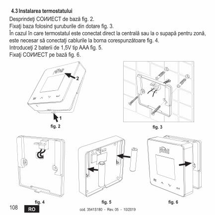
108 RO cod. 3541S180 - Rev. 05 - 10/2019
4.3 instalareatermostatuluiDesprindeţiCOИИECTdebazăfig.2.Fixaţibazafolosindşuruburiledindotarefig.3.Încazulîncaretermostatulesteconectatdirectlacentralăsaulaosupapăpentruzonă,estenecesarsăconectaţicablurilelabornacorespunzătoarefig.4.Introduceţi2bateriide1,5VtipAAAfig.5.FixaţiCOИИECTpebazăfig.6.
�
�
fig.2 fig.3
fig.4 fig.5 fig.6

109ROcod. 3541S180 - Rev. 05 - 10/2019
4.4 Montarea suportului termostatului
7
4.3 Installazione termostatoInserire 2 batterie da 1,5V tipo AAA.4.4 Montaggio supporto termostato
� �
� �
fig. 2 - fig.7-Suportultermostatului

110 RO cod. 3541S180 - Rev. 05 - 10/2019
5. PENTruuTilizaTOrulfiNal
5.1 ButoaneşipictogrameÎncontinuaregăsiţiodescriereasimbolurilorafişatepeecranşiasemnificaţieibutoanelor.
fig.8Pictogramă descriere
Încălzire
Apăcaldămenajeră
Flacără
On/Off(Pornit/Oprit)
ModulAUTOMAT
ModulMANUALModulVACANŢĂ
Pictogramă descriereWireless
WiFi
Nivelscăzutalbateriei
Temperaturăşiorarmod/salvare/ieşiremărirereduceresetTastăLed
111ROcod. 3541S180 - Rev. 05 - 10/2019
Baterie:Cândnivelulbaterieiesteinsuficient,seactiveazăpictogramadepeecran.flacără
» Termostatconectatlaocentralăon-off,pictogramaindicăstareasolicitării. » TermostatconectatlaocentralăOpenTherm,pictogramaindicăstareaarzătorului.
Notă: la prima pornire, termostatul se configurează automat în modul de conectare prin cablu On-Off.Când termostatul şi receptorul Wifi sunt conectate la reţeaua wireless, termostatul se comută automat pe modul RF On-Off.Când receptorul Wifi este conectat la o centrală OpenTherm, termostatul se comută automat pe modul RF OpenTherm.Dacă termostatul este configurat ca RF (on-off sau OpenTherm), nu se comută automat pe modul cablu on-off. Acest lucru se poate face numai prin scoaterea şi punerea la loc a bateriilor.
apăcaldămenajeră:înmodulmanualsauautomat,pictogramaindicăfaptulcăcircuituldeapăcaldămenajerăesteactiv.
Notă: pictograma apare numai în cazul conexiunii RF cu centrale OpenTherm.Încălzire:pictogramaindicăfaptulcăîncălzireaesteactivă.
Notă: pictograma apare numai în cazul conexiunii RF cu centrale OpenTherm.Temperatură:seafişeazătemperaturaambiantăsauerorile:
E82: eroare de comunicare RFE83: eroare de comunicare OpenTherm
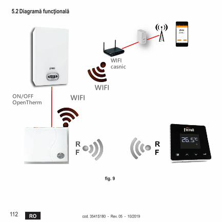
112 RO cod. 3541S180 - Rev. 05 - 10/2019
5.2 diagramăfuncţională
fig.9
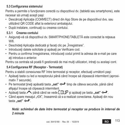
113ROcod. 3541S180 - Rev. 05 - 10/2019
5.3 Configurarea sistemuluiPentruapermiteofuncţionarecorectăcudispozitivuldv.(tabletăsausmartphone),estenecesarsăurmaţiaceştipaşi:• DescărcaţiAplicaţia(COИИECT)directdinAppStoredepedispozitivuldvs.sauutilizândQRCODEaflatlaexteriorulambalajului.
• Dupăinstalare,continuaţicucreareacontului.5.3.1 Crearea contului• Asiguraţi-văcădispozitivuldv.SMARTPHONE/TABLETĂesteconectatlareţeauaWifi.
• DeschideţiAplicaţiadedicatăşifaceţiclicpe„Înregistrare”.• IntroduceţidatelesolicitateşiapăsaţipeVerificarecod.• Pentruaconfirmaînregistrarea,introduceţicodulprimitlaadresadee-mailpecareaţiintrodus-oanterior.
Pentrucacentralasăpoatăfigestionatădemaimulţiutilizatori,intraţicuacelaşicont.5.4 Configurarearf(receptor-Termostat)PentruastabiliconexiuneaRFîntretermostatşireceptor,efectuaţiurmătoriipaşi:• Apăsaţitastaculedareceptoruluipânăcândîncepesăclipeascăintermitent(aproxi-mativ7secunde).
• Petermostatţineţiapăsatătasta„set” ”timpdecâtevasecunde,pânăcândafişajulîncepesăclipeascăintermitent.
• Apăsaţitasta pânăcândsevede şiapăsaţipetasta„set” ”.• Cândaparemesajul„r0X”,înseamnăcăs-arealizatconectarea.Apăsaţidinnoutasta„set” ”.
Notă: schimbul de date între termostat şi receptor se produce în interval de 2 minute
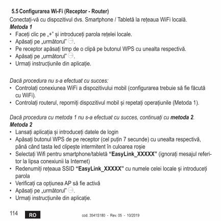
114 RO cod. 3541S180 - Rev. 05 - 10/2019
5.5 ConfigurareaWi-fi(receptor-router)Conectați-văcudispozitivuldvs.Smartphone/TabletălarețeauaWiFilocală.Metoda 1• Facețiclicpe„+”șiintroducețiparolarețeleilocale.• Apăsațipe„următorul” .• PereceptorapăsațitimpdeoclipăpebutonulWPScuunealtarespectivă.• Apăsațipe„următorul” .• Urmațiinstrucțiuniledinaplicație.
Dacă procedura nu s-a efectuat cu succes:• ControlațiconexiuneaWiFiadispozitivuluimobil(configurareatrebuiesăfiefăcutăcuWiFi).
• Controlațirouterul,repornițidispozitivulmobilșirepetațioperațiunile(Metoda1).
Dacă procedura cu metoda 1 nu s-a efectuat cu succes, continuați cu metoda 2.Metoda 2• Lansațiaplicațiașiintroducețidateledelogin• ApăsațibutonulWPSdepereceptor(celpuțin7secunde)cuunealtarespectivă,pânăcândtastaledclipeșteintermitentînculoarearoșie
• SelectațiWifipentrusmartphone/tabletă“Easylink_XXXXX”(ignorațimesajulreferi-torlalipsaconexiuniilaInternet)
• RedenumițirețeauaSSID“Easylink_XXXXX”cunumeleceleilocaleșiintroducețiparola
• VerificațicaopțiuneaAPsăfieactivă• Apăsațipe„următorul” .• Urmațiinstrucțiuniledinaplicație.
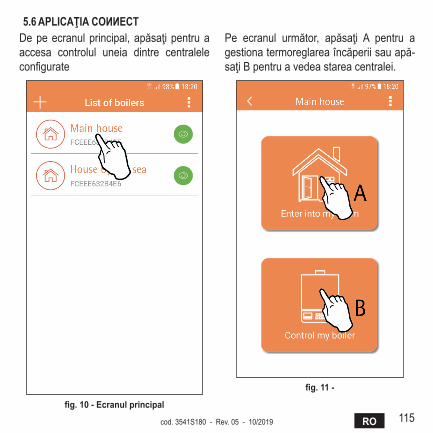
115ROcod. 3541S180 - Rev. 05 - 10/2019
5.6 aPliCaţiaCOИИECTDepeecranulprincipal,apăsaţipentruaaccesa controlul uneia dintre centraleleconfigurate
fig.10-Ecranulprincipal
Pe ecranul următor, apăsaţi A pentru agestionatermoreglareaîncăperiisauapă-saţiBpentruavedeastareacentralei.
fig.11-

116 RO cod. 3541S180 - Rev. 05 - 10/2019
Peacestecranputeţiintraînse-tarea pentru cronocomanda ladistanţăconectată.
fig.12-Controlulcronocomenzii
Modurile posibile sunt:
Modulmanual
Programaresăptămânală
Modulvacanţă
Termostatoprit
fig.13-moduriposibile
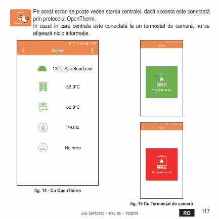
117ROcod. 3541S180 - Rev. 05 - 10/2019
Peacestecransepoatevedeastareacentralei,dacăaceastaesteconectatăprinprotocolulOpenTherm.În cazul în care centrala este conectată la un termostat de cameră, nu seafişeazănicioinformaţie.
fig.14-CuOpenTherm
fig.15CuTermostatdecameră
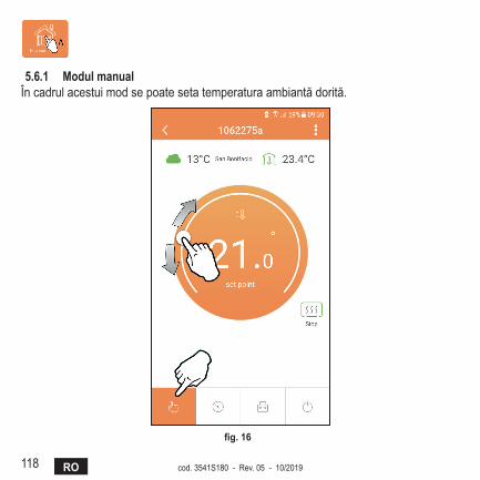
118 RO cod. 3541S180 - Rev. 05 - 10/2019
5.6.1 Modul manualÎncadrulacestuimodsepoatesetatemperaturaambiantădorită.
fig.16
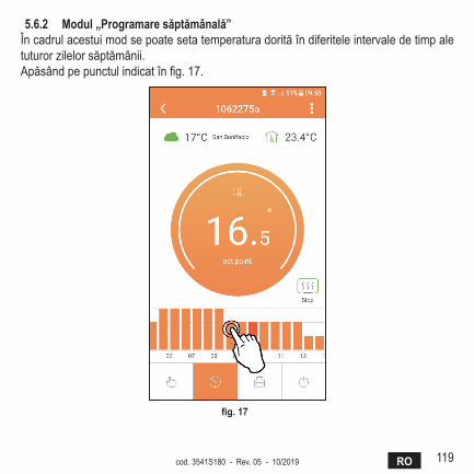
119ROcod. 3541S180 - Rev. 05 - 10/2019
5.6.2 modul„Programaresăptămânală”Încadrulacestuimodsepoatesetatemperaturadorităîndiferiteleintervaledetimpaletuturorzilelorsăptămânii.Apăsândpepunctulindicatînfig.17.
fig.17

120 RO cod. 3541S180 - Rev. 05 - 10/2019
Aveţiladispoziţie3niveluridetemperatură:T3(NivelulCONFORT),T2(NivelulECO)şiT1(NivelulANTIÎNGHEŢ-NupoatefimodificatprinAplicaţie,cinumaiprinintermediulCronocomenziidistanţă).PentruasetatemperaturanivelurilorT2şiT3,urmaţisecvenţa.
fig.18 fig.19Setaţitemperaturileşiconfirmaţi.
fig.20Setarea temperaturilor
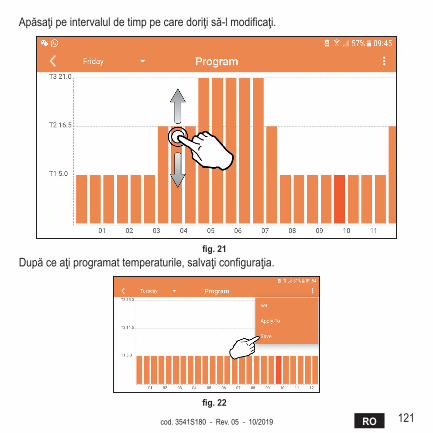
121ROcod. 3541S180 - Rev. 05 - 10/2019
Apăsaţipeintervaluldetimppecaredoriţisă-lmodificaţi.
fig.21Dupăceaţiprogramattemperaturile,salvaţiconfiguraţia.
fig.22
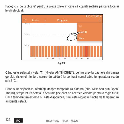
122 RO cod. 3541S180 - Rev. 05 - 10/2019
Faceţiclicpe„aplicare”pentruaalegezileleîncaresăcopiaţisetărilepecaretocmaile-aţiefectuat.
fig.23
CândesteselectatnivelulT1(NivelulANTIÎNGHEŢ),pentruaevitadauneledincauzagerului,sistemultrimiteocereredecăldurălacentralănumaicândtemperaturascadesub5°C.
Dacăsuntdisponibileinformaţiidespretemperaturaexternă(prinWEBsauprinOpen-Therm),temperaturasetatăîncentralăţinecontdeaceastăvaloarepentruareglaturul:Dacătemperaturaexternănuestedisponibilă,turulestereglatînfuncţiedetemperaturaambiantăsetată.
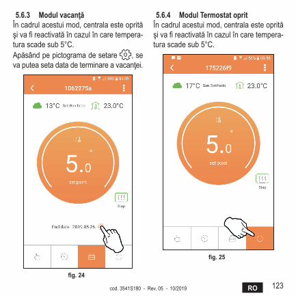
123ROcod. 3541S180 - Rev. 05 - 10/2019
5.6.3 modulvacanţăÎncadrulacestuimod,centralaesteoprităşivafireactivatăîncazulîncaretempera-turascadesub5°C.Apăsândpepictogramadesetare ,sevaputeasetadatadeterminareavacanţei.
fig.24
5.6.4 modulTermostatopritÎncadrulacestuimod,centralaesteoprităşivafireactivatăîncazulîncaretempera-turascadesub5°C.
fig.25

124 RO cod. 3541S180 - Rev. 05 - 10/2019
5.7 Termostat5.7.1 Operaţiidebază
1. Apăsândtasta„mode” puteţicomutaîntrediferitelemoduri:
a. Off :încadrulacestuimod,cerereadecăldurăestedezactivatăşirămâneactivnumaimodulantiîngheţ.
b. Vacanţă :temperaturasetatăesteceapentrueconomiedeenergieantiîn-gheţ,pentruunnumărdezilesetatcuajutorultastelor .
c. automat :temperaturacerutăesteaceeadinprogramulsăptămânalsetatprinintermediul aplicaţiei.Dacă programul nu a fost setat, se utilizează programulimplicitalsistemului.
d. Manual :temperaturaestesetatămanualdirectpetermostat.2. Setarea temperaturii:
a. Manual:cuajutorultastelor .3. meniulSetări:apăsândbutonul„set” timpdeaproximativ2secunde,intraţiîn
meniuldesetări.a. Cu„ şi ”sederuleazămeniulb. Cu„set” seintrăînparametrulselectatc. Cu„mode” serevinelameniulprincipal
4. Încazuluneianomaliiacentralei,esteindicatcoduldeeroareşipeafişajultermosta-tului.Esteposibilsăsedeblochezeanomaliacuajutorultastei„set” .
Pentruodescriereaanomaliei,consultaţimanualulcentralei.
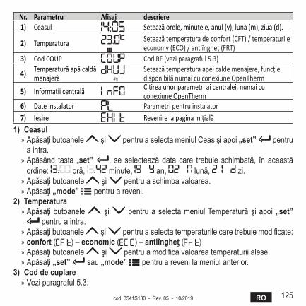
125ROcod. 3541S180 - Rev. 05 - 10/2019
Nr. Parametru Afişaj descriere1) Ceasul Setează orele, minutele, anul (y), luna (m), ziua (d).
2) Temperatura Setează temperatura de confort (CFT) / temperaturile economy (ECO) / antiîngheţ (FRT)
3) Cod COUP Cod RF (vezi paragraful 5.3)
4) Temperatură apă caldă menajeră
Setează temperatura apei calde menajere, funcţie disponibilă numai cu conexiune OpenTherm
5) Informaţii centrală Citirea unor parametri ai centralei, numai cu conexiune OpenTherm
6) Date instalator Parametri pentru instalator7) Ieșire Revenire la pagina iniţială
1)Ceasul » Apăsaţibutoanele şi pentruaselectameniulCeasşiapoi„set” pentruaintra.
» Apăsând tasta „set” , se selecteazădata care trebuie schimbată, în aceastăordine: oră, minute, an, lună, zi.
» Apăsaţibutoanele şi pentruaschimbavaloarea. » Apăsaţi„mode” pentruareveni.
2)Temperatura » Apăsaţibutoanele şi pentruaselectameniulTemperaturăşiapoi„set”
pentruaintra. » Apăsaţibutoanele şi pentruaselectatemperaturilecaretrebuiemodificate: » confort( )–economic( )–antiîngheţ( ) » Apăsaţibutoanele şi pentruamodificavaloareatemperaturiialese. » Apăsaţi„set” sau„mode” pentruarevenilameniulanterior.
3)Cod de cuplare » Veziparagraful5.3.
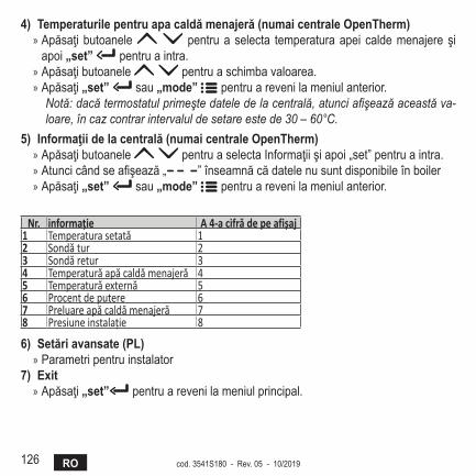
126 RO cod. 3541S180 - Rev. 05 - 10/2019
4)Temperaturilepentruapacaldămenajeră(numaicentraleOpenTherm) » Apăsaţi butoanele pentrua selecta temperaturaapei caldemenajere şiapoi„set” pentruaintra.
» Apăsaţibutoanele pentruaschimbavaloarea. » Apăsaţi„set” sau„mode” pentruarevenilameniulanterior.
Notă: dacă termostatul primeşte datele de la centrală, atunci afişează această va-loare, în caz contrar intervalul de setare este de 30 – 60°C.
5)informaţiidelacentrală(numaicentraleOpenTherm) » Apăsaţibutoanele pentruaselectaInformaţiişiapoi„set”pentruaintra. » Atuncicândseafişează„ ”înseamnăcădatelenusuntdisponibileînboiler » Apăsaţi„set” sau„mode” pentruarevenilameniulanterior.
Nr. informaţie A 4-a cifră de pe afişaj1 Temperatura setată 12 Sondă tur 23 Sondă retur 34 Temperatură apă caldă menajeră 45 Temperatură externă 56 Procent de putere 67 Preluare apă caldă menajeră 78 Presiune instalaţie 8
6)Setăriavansate(Pl) » Parametripentruinstalator
7)Exit » Apăsaţi„set” pentruarevenilameniulprincipal.
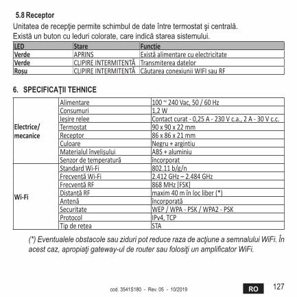
127ROcod. 3541S180 - Rev. 05 - 10/2019
5.8ReceptorUnitateaderecepţiepermiteschimbuldedateîntretermostatşicentrală.Existăunbutonculeduricolorate,careindicăstareasistemului.LED Stare FuncţieVerde APRINS Există alimentare cu electricitateVerde CLIPIRE INTERMITENTĂ Transmiterea datelorRoşu CLIPIRE INTERMITENTĂ Căutarea conexiunii WIFI sau RF
6. SPECifiCaţiiTEhNiCE
Electrice/mecanice
Alimentare 100 ~ 240 Vac, 50 / 60 HzConsumuri 1,2 WIeșire relee Contact curat - 0,25 A - 230 V c.a., 2 A - 30 V c.c.Termostat 90 x 90 x 22 mmReceptor 86 x 86 x 21 mmCuloare Negru + argintiuMaterialul învelișului ABS + aluminiuSenzor de temperatură încorporat
Wi-Fi
Standard Wi-Fi 802.11 b/g/nFrecvenţă Wi-Fi 2.412 GHz – 2.484 GHzFrecvenţă RF 868 MHz [FSK]Distanţă RF maxim 40 m în loc liber (*)Antenă încorporatăSecuritate WEP / WPA - PSK / WPA2 - PSKProtocol IPv4, TCPTip de reţea STA
(*) Eventualele obstacole sau ziduri pot reduce raza de acţiune a semnalului WiFi. În acest caz, apropiaţi gateway-ul de router sau folosiţi un amplificator WiFi.
128 RU cod. 3541S180 - Rev. 05 - 10/2019
1. Предисловие ............................................................................................... 129
2. Общиеправилатехникибезопасности .................................................. 129
3. КлассуправленияпорегламентуErP .................................................... 129
4. Инструкциидляустановщика .................................................................. 1304.1 Содержание .............................................................................................. 1304.2 Установкаприемника ............................................................................... 1314.3 Установкатермостата .............................................................................. 1334.4 Монтажопорытермостата ...................................................................... 1345. Инструкциидляконечногопользователя ............................................. 1355.1 Кнопкиизначки ........................................................................................ 1355.2 Функциональнаясхема ............................................................................ 1375.3 Конфигурациясистемы ........................................................................... 1385.3.1 Созданиеучетнойзаписи ............................................................... 1385.4 КонфигурацияРЧ-соединения(«приемник-термостат») .................... 1385.5 КонфигурацияWi-Fi(приемник-маршрутизатор) ................................... 1395.6 ПриложениеCOИИECT ........................................................................... 1405.6.1 Ручнойрежим .................................................................................. 1435.6.2 Режим«Еженедельноепрограммирование» ................................ 1445.6.3 Режим"Отпуск" ................................................................................ 1485.6.4 Режим"Термостатвыключен" ........................................................ 1485.7 Термостат ................................................................................................. 1495.7.1 Основныеоперации ........................................................................ 1495.8 Приемник .................................................................................................. 1526. Техническиехарактеристики ................................................................... 152
129RUcod. 3541S180 - Rev. 05 - 10/2019
1. ПредИслОвИеУважаемыйпокупатель,спасибозавыбор«умного»термостатаCOИИECT.Сегопомощьювысможетесточностьюотслеживатьтемпературувпомещениии,благо-дарятехнологииWi-Fi,управлятьимдистанционноспомощьюспециальногопрограмм-ногоприложения.Данноеруководствопредназначенодляустановщиковиконечныхпользователей.Основнымэлементомсистемыявляетсяхронотермостат,которыйспособенуправлятьпрограммами,задаваемымичерезприложение,измерятьместнуютемпературуипосы-латьсигналывключения/выключениянаблокдистанционногоуправления,подключен-ныйнепосредственноккотлу.2. ОбщИеПравИлаТехнИКИбезОПаснОсТИ• Внимательнопрочитайтеинструкции,приведенныевэтомруководстве.• Послеустановкипроинформируйтепользователяофункциональныхвозможностях
устройстваиоставьтеемуэторуководстводлябережногохранениявкачественеотъемлемойчастиизделияиобращениязасправкойвбудущем.
• Монтажитехническоеобслуживаниедолжнывыполнятьсяопытнымиквалифици-рованнымперсоналомвсоответствиисдействующимиправиламииинструкциямипроизводителя.Невыполняйтеникакихоперацийнаопечатанныхэлементахуправ-ления.
• Отключайтеисточникпитанияпередпроведениемчистки.• Неразмещайтеустройстворядомсисточникамитепла.• Хранитеустройствовнедоступномдлядетейместе.3. КлассуПравленИяПОрегламенТуErPВ соответствии с Делегированным регламентом Евросоюза (ЕС)№811/2013 данные,представленныевтаблице,могутиспользоватьсядлямаркировкиотопительнойтехники.ВозможныекомбинациисCOИИECT,соответствующиеклассыконфигурациииэнерге-тическаядолявсистеме.
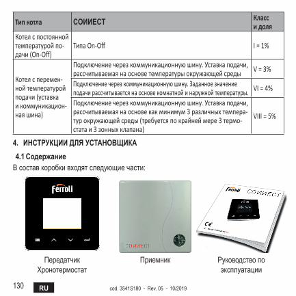
130 RU cod. 3541S180 - Rev. 05 - 10/2019
Тип котла COИИECT Класс и доля
Котел с постоянной температурой по-дачи (On‑Off)
Типа On‑Off I = 1%
Котел с перемен-ной температурой подачи (уставка и коммуникацион-ная шина)
Подключение через коммуникационную шину. Уставка подачи, рассчитываемая на основе температуры окружающей среды V = 3%
Подключение через коммуникационную шину. Заданное значение подачи рассчитывается на основе комнатной и наружной температуры. VI = 4%
Подключение через коммуникационную шину. Уставка подачи, рассчитываемая на основе как минимум 3 различных темпера-тур окружающей среды (требуется по крайней мере 3 термо-стата и 3 зонных клапана)
VIII = 5%
4. ИнсТруКцИИдляусТанОвщИКа4.1 содержаниеВсоставкоробкивходятследующиечасти:
ПередатчикХронотермостат
Приемник Руководствопоэксплуатации
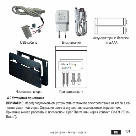
131RUcod. 3541S180 - Rev. 05 - 10/2019
USB-кабель БлокпитанияАккумуляторныебатареи
типаAAA
Настольнаяопора Принадлежности
4.2 установкаприемникавнИманИе:передподключениемустройстваотключитеэлектропитаниеоткотлавка-чествезащитноймеры.Операциядолжнаосуществлятьсяопытнымперсоналом.Приемник может работать с протоколом OpenTherm или через контакт On-Off ("Вкл./Выкл.").
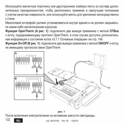
132 RU cod. 3541S180 - Rev. 05 - 10/2019
Используйтемагнитнуюпластинкуилидвустороннююклейкуюлентуизсоставадопол-нительных принадлежностей, чтобы расположить приемник в наилучшем положениисучетомкачестваповерхности,илииспользуйтевинтыдлякреплениянепосредственнокстене.Межсетевойинтерфейсдолженустанавливатьсявнутризданияинедолжензакрывать-сякаким-либометаллическимкорпусом.ФункцияOpenTherm (Aрис.1): подключитедвавыводаприемникасметкойOTBus ккотлу,поддерживающемупротоколOpenTherm.вэтомслучаедоступнадополнитель-наяинформацияосостояниикотла«5.7.1Основныеоперации»настр.149.ФункцияOn-Off(Bрис.1):подключитедвавыводаприемникасметкойON/OFFккотлу,неимеющемупротоколасвязиOpenTherm.
����� ������
����� ������
�
�
рис.1Послевключенияэлектропитаниянамгновениезажгутсясветодиоды.
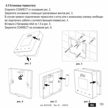
133RUcod. 3541S180 - Rev. 05 - 10/2019
4.3 установкатермостатаОтделитеCOИИECTотоснованиярис.2.Закрепитеоснованиеспомощьюприлагаемыхвинтоврис.3.Вслучаепрямогоподключениятермостатаккотлуиликзональномуклапанунеобходи-моподключитькабеликсоответствующейклеммерис.4.Вставьте2батарейкиАААпо1,5врис.5.ЗакрепитеCOИИECTнаоснованиирис.6.
�
�
рис.2 рис.3
рис.4 рис.5 рис.6
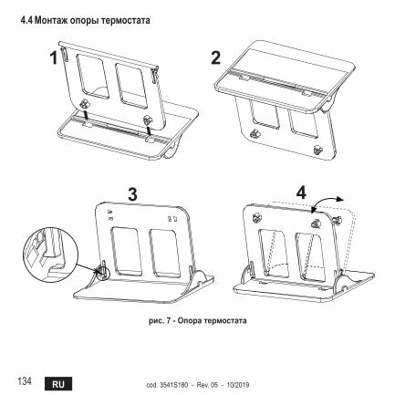
134 RU cod. 3541S180 - Rev. 05 - 10/2019
4.4 монтажопорытермостата
7
4.3 Installazione termostatoInserire 2 batterie da 1,5V tipo AAA.4.4 Montaggio supporto termostato
� �
� �
fig. 2 - рис.7-Опоратермостата
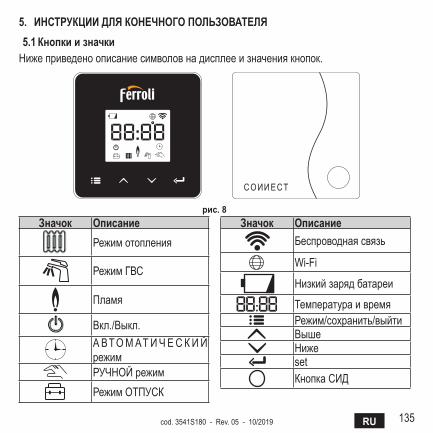
135RUcod. 3541S180 - Rev. 05 - 10/2019
5. ИнсТруКцИИдляКОнечнОгОПОльзОваТеля5.1 КнопкиизначкиНижеприведеноописаниесимволовнадисплееизначениякнопок.
рис.8значок Описание
Режимотопления
РежимГВС
Пламя
Вкл./Выкл.А ВТОМАТИЧЕС КИЙрежимРУЧНОЙрежимРежимОТПУСК
значок ОписаниеБеспроводнаясвязь
Wi-Fi
Низкийзарядбатареи
ТемператураивремяРежим/сохранить/выйтиВышеНижеsetКнопкаСИД
136 RU cod. 3541S180 - Rev. 05 - 10/2019
батарея:Принедостаточномуровнезарядабатареинаэкранезажигаетсясоответству-ющийзначок.Пламя
» ТермостатподключенккотлутипаOn-Off:значокпоказываетсостояниезапроса. » Термостатподключен к котлу типаOpenTherm: значокпоказывает состояниегорелки.Примечания: при первом включении термостата он автоматически на-страивается на кабельное подключение типа On-Off.Когда термостат и приемник Wi-Fi подключены к беспроводной сети, тер-мостат автоматически переключается в радиочастотный режим On-Off.Когда приемник Wi-Fi подключен к котлу через OpenTherm, термостат ав-томатически переключается в радиочастотный режим OpenTherm.Если термостат был настроен на радиочастотное подключение (On-Off или OpenTherm), он не переключается автоматически в кабельный режим On-Off. Это можно сделать только путем вынимания и обратной установ-ки на место батарей.
гвс:вручномилиавтоматическомрежимезначокуказывает,чторежимГВСактивен.Примечание: значок присутствует только в случае радиочастотного со-единения с котлами OpenTherm.
Отопление:значокуказываетнавключенныйрежимотопления.Примечание: значок присутствует только в случае радиочастотного со-единения с котлами OpenTherm.
Температура:отображаетсятемпературавоздухавпомещенииилиошибки:E82: ошибка радиочастотного соединенияE83: ошибка связи OpenTherm

137RUcod. 3541S180 - Rev. 05 - 10/2019
5.2 Функциональнаясхема
ЛокальнаяWi-Fi
ON/OFF OpenTherm
Wi-Fi
Wi-Fi
рис.9
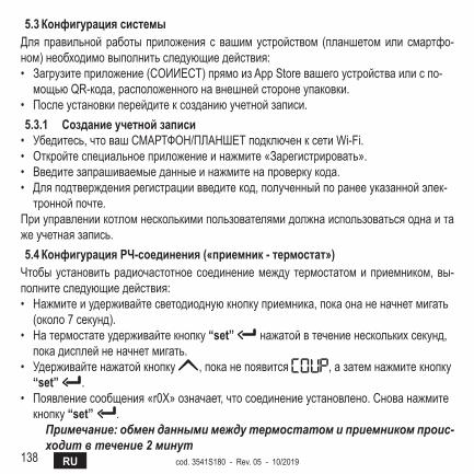
138 RU cod. 3541S180 - Rev. 05 - 10/2019
5.3 КонфигурациясистемыДляправильнойработыприложения с вашимустройством (планшетомили смартфо-ном)необходимовыполнитьследующиедействия:• Загрузитеприложение(COИИECT)прямоизAppStoreвашегоустройстваилиспо-
мощьюQR-кода,расположенногонавнешнейсторонеупаковки.• Послеустановкиперейдитексозданиюучетнойзаписи.5.3.1 созданиеучетнойзаписи• Убедитесь,чтовашСМАРТФОН/ПЛАНШЕТподключенксетиWi-Fi.• Откройтеспециальноеприложениеинажмите«Зарегистрировать».• Введитезапрашиваемыеданныеинажмитенапроверкукода.• Дляподтверждениярегистрациивведитекод,полученныйпоранееуказаннойэлек-
троннойпочте.Приуправлениикотломнесколькимипользователямидолжнаиспользоватьсяоднаитажеучетнаязапись.5.4 Конфигурациярч-соединения(«приемник-термостат»)Чтобыустановитьрадиочастотноесоединениемеждутермостатомиприемником,вы-полнитеследующиедействия:• Нажмитеиудерживайтесветодиоднуюкнопкуприемника,покаонаненачнетмигать
(около7секунд).• Натермостатеудерживайтекнопку“set” нажатойвтечениенесколькихсекунд,
покадисплейненачнетмигать.• Удерживайтенажатойкнопку ,поканепоявится ,азатемнажмитекнопку
“set” .• Появлениесообщения«r0X»означает,чтосоединениеустановлено.Снованажмите
кнопку“set” .Примечание: обмен данными между термостатом и приемником проис-ходит в течение 2 минут
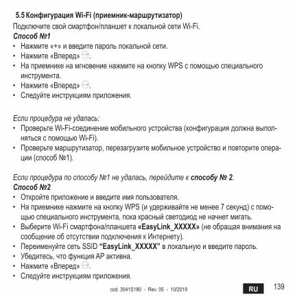
139RUcod. 3541S180 - Rev. 05 - 10/2019
5.5 КонфигурацияWi-Fi(приемник-маршрутизатор)Подключитесвойсмартфон/планшетклокальнойсетиWi-Fi.Способ №1• Нажмите«+»ивведитепарольлокальнойсети.• Нажмите«Вперед» .• НаприемникенамгновениенажмитенакнопкуWPSспомощьюспециального
инструмента.• Нажмите«Вперед» .• Следуйтеинструкциямприложения.
Если процедура не удалась:• ПроверьтеWi-Fi-соединениемобильногоустройства(конфигурациядолжнавыпол-
нятьсяспомощьюWi-Fi).• Проверьтемаршрутизатор,перезагрузитемобильноеустройствоиповторитеопера-
ции(способ№1).
Если процедура по способу №1 не удалась, перейдите к способу № 2.Способ №2• Откройтеприложениеивведитеимяпользователя.• НаприемникенажмитенакнопкуWPS(иудерживайтенеменее7секунд)спомо-
щьюспециальногоинструмента,покакрасныйсветодиодненачнетмигать.• ВыберитеWi-Fiсмартфона/планшета«EasyLink_XXXXX»(необращаявниманияна
сообщениеоботсутствииподключениякИнтернету).• ПереименуйтесетьSSID“EasyLink_XXXXX”влокальнуюивведитепароль.• Убедитесь,чтофункцияAPактивна.• Нажмите«Вперед» .• Следуйтеинструкциямприложения.
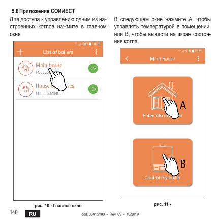
140 RU cod. 3541S180 - Rev. 05 - 10/2019
5.6 ПриложениеCOИИECTДлядоступакуправлениюоднимизна-строенных котлов нажмите в главномокне
рис.10-главноеокно
В следующем окне нажмите A, чтобыуправлять температуройв помещении,илиB,чтобывывестинаэкрансостоя-ниекотла.
рис.11-
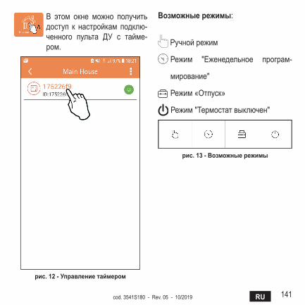
141RUcod. 3541S180 - Rev. 05 - 10/2019
В этом окне можно получитьдоступ к настройкам подклю-ченного пульта ДУ с тайме-ром.
рис.12-управлениетаймером
возможныережимы:
Ручнойрежим
Режим "Еженедельное програм-
мирование"
Режим«Отпуск»
Режим"Термостатвыключен"
рис.13-возможныережимы
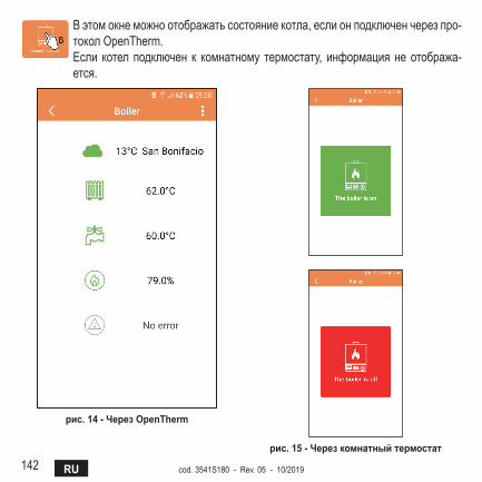
142 RU cod. 3541S180 - Rev. 05 - 10/2019
Вэтомокнеможноотображатьсостояниекотла,еслионподключенчерезпро-токолOpenTherm.Если котелподключен к комнатному термостату, информациянеотобража-ется.
рис.14-черезOpenTherm
рис.15-черезкомнатныйтермостат
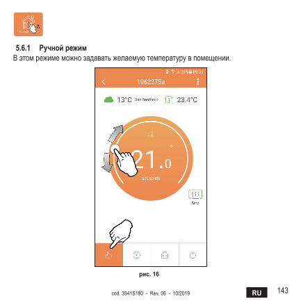
143RUcod. 3541S180 - Rev. 05 - 10/2019
5.6.1 ручнойрежимВэтомрежимеможнозадаватьжелаемуютемпературувпомещении.
рис.16
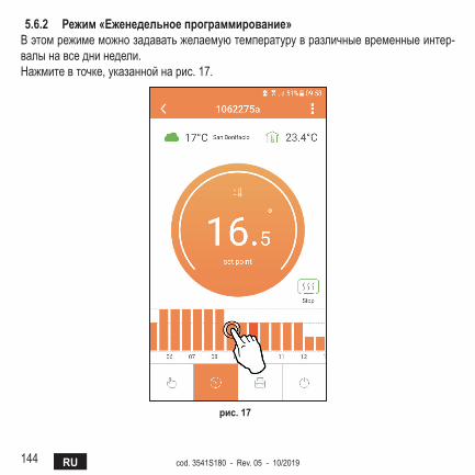
144 RU cod. 3541S180 - Rev. 05 - 10/2019
5.6.2 режим«еженедельноепрограммирование»Вэтомрежимеможнозадаватьжелаемуютемпературувразличныевременныеинтер-валынавседнинедели.Нажмитевточке,указаннойнарис.17.
рис.17
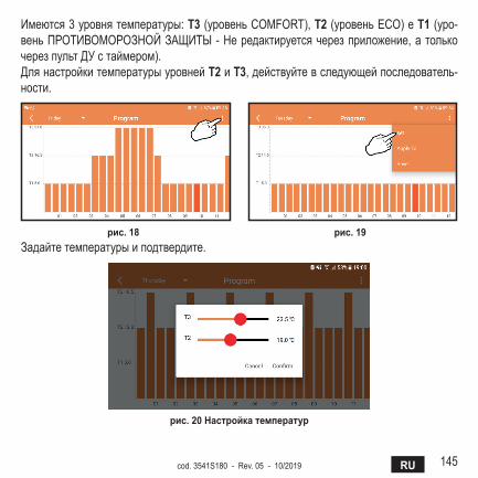
145RUcod. 3541S180 - Rev. 05 - 10/2019
Имеются3уровнятемпературы:T3(уровеньCOMFORT),T2(уровеньECO)eT1(уро-веньПРОТИВОМОРОЗНОЙЗАЩИТЫ-Нередактируетсячерезприложение,атолькочерезпультДУстаймером).ДлянастройкитемпературыуровнейT2иT3,действуйтевследующейпоследователь-ности.
рис.18 рис.19Задайтетемпературыиподтвердите.
рис.20настройкатемператур
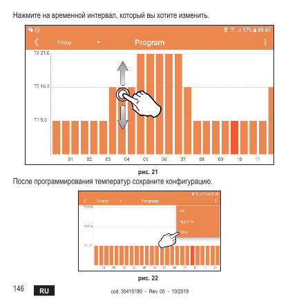
146 RU cod. 3541S180 - Rev. 05 - 10/2019
Нажмитенавременнойинтервал,которыйвыхотитеизменить.
рис.21Послепрограммированиятемпературсохранитеконфигурацию.
рис.22
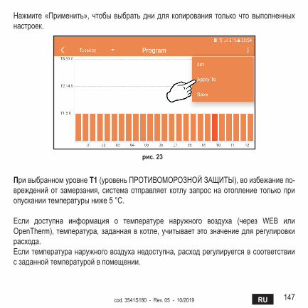
147RUcod. 3541S180 - Rev. 05 - 10/2019
Нажмите«Применить»,чтобывыбратьднидлякопированиятолькочтовыполненныхнастроек.
рис.23
ПривыбранномуровнеT1(уровеньПРОТИВОМОРОЗНОЙЗАЩИТЫ),воизбежаниепо-врежденийотзамерзания,системаотправляет котлузапроснаотоплениетолькоприопусканиитемпературыниже5°C.
Если доступна информация о температуре наружного воздуха (через WEB илиOpenTherm),температура,заданнаявкотле,учитываетэтозначениедлярегулировкирасхода.Еслитемпературанаружноговоздуханедоступна,расходрегулируетсявсоответствиисзаданнойтемпературойвпомещении.

148 RU cod. 3541S180 - Rev. 05 - 10/2019
5.6.3 режим"Отпуск"В этом режиме котел выключаетсяивключаетсятолькотогда,когдатемпе-ратураопускаетсяниже5°C.Нажавзначокнастройки ,выможетеустановитьдатуокончанияотпуска.
рис.24
5.6.4 режим"Термостатвыключен"В этом режиме котел выключаетсяивключаетсятолькотогда,когдатемпе-ратураопускаетсяниже5°C.
рис.25
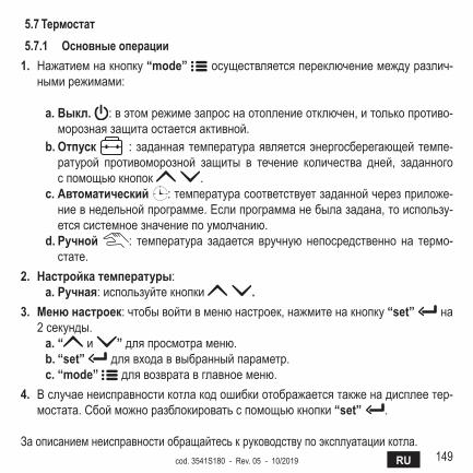
149RUcod. 3541S180 - Rev. 05 - 10/2019
5.7Термостат5.7.1 Основныеоперации
1. Нажатиемнакнопку“mode” осуществляетсяпереключениемеждуразлич-нымирежимами:
a.выкл. :вэтомрежимезапроснаотоплениеотключен,итолькопротиво-морознаязащитаостаетсяактивной.
b. Отпуск :заданнаятемператураявляетсяэнергосберегающейтемпе-ратурой противоморозной защиты в течение количества дней, заданногоспомощьюкнопок .
c. автоматический :температурасоответствуетзаданнойчерезприложе-ниевнедельнойпрограмме.Еслипрограмманебылазадана,тоиспользу-етсясистемноезначениепоумолчанию.
d.ручной : температура задается вручнуюнепосредственно на термо-стате.
2. настройкатемпературы:a.ручная:используйтекнопки .
3. менюнастроек:чтобывойтивменюнастроек,нажмитенакнопку“set” на2секунды.a.“ и ”дляпросмотраменю.b. “set” длявходаввыбранныйпараметр.c. “mode” длявозвратавглавноеменю.
4. Вслучаенеисправностикотлакодошибкиотображаетсятакженадисплеетер-мостата.Сбойможноразблокироватьспомощьюкнопки“set” .
Заописаниемнеисправностиобращайтеськруководствупоэксплуатациикотла.
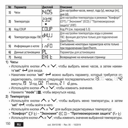
150 RU cod. 3541S180 - Rev. 05 - 10/2019
№ Параметр Дисплей Описание
1) Часы Для настройки часов, минут, года (y), месяца (m), дня (d).
2) Температура Для настройки температуры в режимах "Комфорт" (CFT) / "Экономия" (ECO) / "Противоморозная защита" (FRT)
3) Код COUP Код РЧ (см. параграф 5.3)
4) Температура воды ГВСДля настройки температуры воды в режиме ГВС: функция доступна только для подключения OpenTherm.
5) Информация о котле Считывание некоторых параметров котла только при подключении OpenTherm.
6) Данные установщика Параметры для установщика7) Выход Возвращение на начальную страницу
1)часы » Используйте кнопки и , чтобы выбратьменю часов, а затем нажми-те“set” длявхода.
» Нажатием кнопки “set” можно выбрать параметр, который требуетсяот-редактировать,согласноследующейпоследовательности: часы, минуты, год, месяц, день.
» Используйтекнопки и ,чтобыизменитьзначение. » Нажмите“mode” ,чтобывернутьсяназад.
2)Температура » Используйте кнопки и , чтобы выбрать меню температуры, а затем“set” ,чтобывойтивнего.
» Используйтекнопки и длявыбораредактируемыхтемператур: » "Комфорт"( )–"Экономия"( )–"Противоморознаязащита"( ) » Используйтекнопки и ,чтобыизменитьзначениевыбраннойтемпературы.
151RUcod. 3541S180 - Rev. 05 - 10/2019
» Нажмите“set” или“mode” ,чтобывернутьсявпредыдущееменю.3)Кодсвязи
» См.параграф5.3.4)Температурыгвс(толькодлякотловOpenTherm)
» Используйтекнопки ,чтобывыбратьменютемпературыГВС,азатем“set” ,чтобывойтивнего.
» Используйтекнопки ,чтобыизменитьзначение. » Нажмитe“set” или“mode” ,чтобывернутьсявпредыдущееменю.
Примечание: если термостат получает информацию от котла, он отоб-ражает это значение, в противном случае диапазон настройки составляет 30 - 60°C.
5)Информацияоткотла(толькодлякотловOpenTherm) » Используйтекнопки ,чтобывыбратьменюинформации,азатем“set”,чтобывойтивнего.
» Отображение “ ” означает, что данная конкретная информация в котленедоступна.
» Нажмитe“set” или“mode” ,чтобывернутьсявпредыдущееменю.№ Информация 4я цифра на дисплее
1 Заданная температура 12 Датчик в подающем контуре 23 Датчик в обратном контуре 34 Температура воды ГВС 45 Температура в помещении 56 Процент мощности 67 Забор ГВС 78 Давление в системе 8
6)расширенныенастройки(PL) » Параметрыдляустановщика
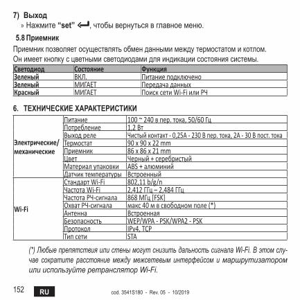
152 RU cod. 3541S180 - Rev. 05 - 10/2019
7)выход » Нажмите“set” ,чтобывернутьсявглавноеменю.
5.8ПриемникПриемникпозволяетосуществлятьобменданнымимеждутермостатомикотлом.Онимееткнопкусцветнымисветодиодамидляиндикациисостояниясистемы.Светодиод Состояние ФункцияЗеленый ВКЛ. Питание подключеноЗеленый МИГАЕТ Передача данныхКрасный МИГАЕТ Поиск сети Wi‑Fi или РЧ
6. ТехнИчесКИехараКТерИсТИКИ
Электрические/механические
Питание 100 ~ 240 в пер. тока, 50/60 ГцПотребление 1,2 ВтВыход реле Чистый контакт ‑ 0,25А ‑ 230 В пер. тока, 2А ‑ 30 В пост. токаТермостат 90 x 90 x 22 mmПриемник 86 x 86 x 21 mmЦвет Черный + серебристыйМатериал упаковки ABS + алюминийДатчик температуры Встроенный
Wi-Fi
Стандарт Wi‑Fi 802,11 b/g/nЧастота Wi‑Fi 2,412 ГГц – 2,484 ГГцЧастота РЧ‑сигнала 868 MГц [FSK]Охват РЧ‑сигнала макс 40 м в свободном поле (*) Антенна ВстроеннаяБезопасность WEP/WPA ‑ PSK/WPA2 ‑ PSKПротокол IPv4, TCPТип сети STA
(*) Любые препятствия или стены могут снизить дальность сигнала Wi-Fi. В этом слу-чае сократите расстояние между межсетевым интерфейсом и маршрутизатором или используйте ретранслятор Wi-Fi.
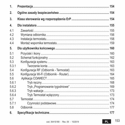
153PLcod. 3541S180 - Rev. 05 - 10/2019
1. Prezentacja ................................................................................................... 154
2. Ogólnezasadybezpieczeństwa ................................................................. 154
3. KlasasterowaniawgrozporządzeniaErP ................................................. 154
4. Dla instalatora .............................................................................................. 1554.1 Zawartość .................................................................................................. 1554.2 Wymiana odbiornika .................................................................................. 1564.3 Instalacja termostatu.................................................................................. 1584.4 Montażwspornikatermostatu .................................................................... 1595. Dlaużytkownikakońcowego ...................................................................... 1605.1 Przyciski i ikony ......................................................................................... 1605.2 Schemat funkcjonalny ............................................................................... 1625.3 Konfiguracja systemu ................................................................................ 1635.3.1 Tworzenie konta ................................................................................ 1635.4 Konfiguracja RF (Odbiornik - Termostat) ................................................... 1635.5 Konfiguracja Wi-Fi (Odbiornik - Router)..................................................... 1645.6 AplikacjaCOИИECT ................................................................................. 1655.6.1 Trybręczny........................................................................................ 1685.6.2 Tryb „Programowanie tygodniowe” ................................................... 1695.6.3 Tryb wakacje ..................................................................................... 1735.6.4 TrybTermostatwyłączony ................................................................. 1735.7 Termostat ................................................................................................... 1745.7.1 Czynnościpodstawowe ..................................................................... 1745.8 Odbiornik ................................................................................................... 1776. Specyfikacjetechniczne .............................................................................. 177
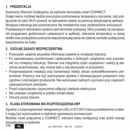
154 PL cod. 3541S180 - Rev. 05 - 10/2019
1. PrEzEntacjaSzanownyKliencie!DziękujemyzawybranietermostatusmartCOИИECT.Dziękiniemumożliwebędzieprecyzyjnekontrolowanietemperaturyotoczenia,zaśpod-łączeniedosieciWi-Fipozwolinasterowaniezdalnezapomocądedykowanejaplikacji.Niniejszainstrukcjajestprzeznaczonadlainstalatoróworazużytkownikówkońcowych.Podstawowymelementemsystemujesttermostatpokojowy,którypozwalanazarządza-nieprogramamigodzinowymiustawionymiwaplikacji,mierzenie temperaturywdanejstrefieorazprzesyłaniepoleceniawłączenia/wyłączeniadozdalnejcentralkipodłączonejbezpośredniodokotła.
2. OgólnEzaSaDybEzPiEczEńStwa• Przeczytaćuważniewszystkieinformacjezawartewniniejszejinstrukcji.• Pozainstalowaniupoinformowaćużytkownikaofunkcjachurządzeniaorazpozosta-wićmuniniejsząinstrukcję.Stanowionaintegralnączęśćurządzeniainależyjąsta-rannieprzechowywać,abymożnabyłozniejskorzystaćwprzyszłości.
• Przeprowadzanie instalacjiorazkonserwacjinależyzlecaćwykwalifikowanemuper-sonelowi.Powinnyonebyćwykonywanezgodniezobowiązującymiprzepisamiorazzgodniezinstrukcjamiproducenta.Niewykonywaćżadnychczynnościprzyczęściachzabezpieczonychplombami.
• Przedrozpoczęciemczyszczeniaodłączyćzasilanieelektryczne.• Nieustawiaćurządzeniawpobliżuźródełciepła.• Chronićprzeddziećmi.
3. KlaSaStErOwaniawgrOzPOrząDzEniaErPZgodniezrozporządzeniemdelegowanym(UE)nr811/2013daneprzedstawionewtabe-limogąbyćwykorzystanewetykiecieogrzewaczypomieszczeń.MożliwenowepołączeniazCOИИECT,odnośneklasykonfiguracjiorazpobórenergiienergetyczny w systemie.
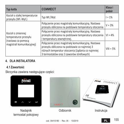
155PLcod. 3541S180 - Rev. 05 - 10/2019
Typ kotła cOИИEct Klasa i pobór
Kocioł o stałej temperaturze przesyłu (Wł.-Wył.) Typ Wł./Wył. I = 1%
Kocioł o zmiennej temperaturze przesyłu (nastawa za pomocą magistrali komunikacyjnej)
Połączenie przez magistralę komunikacyjną. Nastawa przesyłu obliczona na podstawie temperatury otoczenia V = 3%
Połączenie przez magistralę komunikacyjną. Nastawa przesyłu obliczona na podstawie temperatury otoczenia i temperatury zewnętrznej.
VI = 4%
Połączenie przez magistralę komunikacyjną. Nastawa przesyłu obliczona na podstawie co najmniej 3 różnych temperatur otoczenia (żądania co najmniej 3 termostatów oraz 3 zaworów strefowych)
VIII = 5%
4. DlainStalatOra
4.1 zawartośćSkrzynkazawieranastępująceczęści:
Nadajniktermostatpokojowy
Odbiornik Instrukcja
156 PL cod. 3541S180 - Rev. 05 - 10/2019
PrzewódUSB Zasilacz BaterieAAA
Wspornikstołowy Akcesoria
4.2 wymianaodbiornikaUwaga:Odłączyćkociołodzasilaniaprzedprzystąpieniemdowykonaniapodłączenia,abyzabezpieczyćurządzenie.Czynnośćpowinnabyćwykonywanaprzezwykwalifiko-wanypersonel.OdbiornikmożepracowaćzprotokołemOpenThermlubzestykiemWł.-Wył.
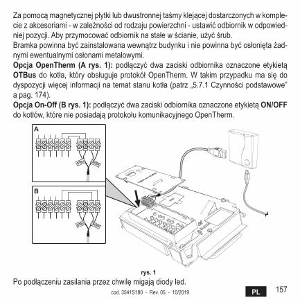
157PLcod. 3541S180 - Rev. 05 - 10/2019
Zapomocąmagnetycznejpłytkilubdwustronnejtaśmyklejącejdostarczonychwkomple-ciezakcesoriami-wzależnościodrodzajupowierzchni-ustawićodbiornikwodpowied-niejpozycji.Abyprzymocowaćodbiorniknastałewścianie,użyćśrub.Bramkapowinnabyćzainstalowanawewnątrzbudynkuiniepowinnabyćosłoniętażad-nymiewentualnymiosłonamimetalowymi.OpcjaOpentherm (a rys. 1): podłączyć dwa zaciski odbiornika oznaczone etykietąOtbusdokotła,któryobsługujeprotokółOpenTherm.W takimprzypadkumasiędodyspozycjiwięcejinformacjinatematstanukotła(patrz„5.7.1Czynnościpodstawowe”apag.174).OpcjaOn-Off(brys.1):podłączyćdwazaciskiodbiornikaoznaczoneetykietąOn/OFF dokotłów,którenieposiadająprotokołukomunikacyjnegoOpenTherm.
����� ������
����� ������
�
�
rys. 1 Popodłączeniuzasilaniaprzezchwilęmigajądiodyled.
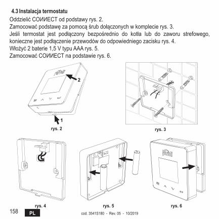
158 PL cod. 3541S180 - Rev. 05 - 10/2019
4.3 instalacjatermostatuOddzielićCOИИECTodpodstawyrys.2.Zamocowaćpodstawęzapomocąśrubdołączonychwkomplecierys.3.Jeśli termostat jest podłączony bezpośrednio do kotła lub do zaworu strefowego,koniecznejestpodłączenieprzewodówdoodpowiedniegozaciskurys.4.Włożyć2baterie1,5VtypuAAArys.5.ZamocowaćCOИИECTnapodstawierys.6.
�
�
rys. 2 rys. 3
rys. 4 rys. 5 rys. 6

159PLcod. 3541S180 - Rev. 05 - 10/2019
4.4 Montażwspornikatermostatu
7
4.3 Installazione termostatoInserire 2 batterie da 1,5V tipo AAA.4.4 Montaggio supporto termostato
� �
� �
fig. 2 - rys. 7 -wsporniktermostatu
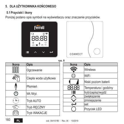
160 PL cod. 3541S180 - Rev. 05 - 10/2019
5. DlaUżytKOwniKaKOńcOwEgO
5.1 PrzyciskiiikonyPoniżejpodanoopissymbolinawyświetlaczuorazznaczenieprzycisków.
rys. 8 ikona Opis
Ogrzewanie
Ciepławodaużytkowa
Płomień
Wł./Wył.
TrybAUTO
TrybRĘCZNYTrybWAKACJE
ikona OpisWireless
WiFi
Niskipoziombaterii
Temperaturaigodzinytryb/zapisz/wyjdźzwiększeniezmniejszeniesetPrzyciskLED
161PLcod. 3541S180 - Rev. 05 - 10/2019
bateria:Kiedypoziombateriijestniewystarczający,naekraniewłączasięodpowiedniaikona.Płomień
» Wprzypadku termostatupodłączonegodokotłaon-off ta ikona informujeostanieżądania.
» W przypadku termostatu podłączonego do kotła OpenTherm ta ikona informujeostaniepalnika.Uwagi: W momencie pierwszego włączenia termostat automatycznie się konfiguruje w trybie podłączenia do przewodu On-Off.Kiedy termostat oraz odbiornik Wifi są podłączone do sieci wireless, termostat automatycznie przełącza się do trybu RF On-Off.Kiedy odbiornik Wifi jest podłączony do kotła OpenTherm, termostat automatycznie przełącza się do trybu RF OpenTherm.Jeśli termostat jest skonfigurowany jako RF (on-off lub OpenTherm), nie przełącza się automatycznie do trybu przewód on-off. Może to zostać wykonane tylko poprzez wyjęcie i ponowne włożenie baterii.
ciepła woda użytkowa: W trybie ręcznym lub automatycznym ikona ta informuje,włączonajestciepławodaużytkowa.
Uwagi: Ikona ta pojawia się wyłącznie wtedy, kiedy obecne jest połączenie RF z kotłami OpenTherm.
Ogrzewanie:Ikonatainformuje,żewłączonejestogrzewanie.Uwagi: Ikona ta pojawia się wyłącznie wtedy, kiedy obecne jest połączenie RF z kotłami OpenTherm.
temperatura:Wyświetlasiętemperaturaotoczenialubbłędy:E82: Błąd komunikacji RFE83: Błąd komunikacji OpenTherm

162 PL cod. 3541S180 - Rev. 05 - 10/2019
5.2 Schematfunkcjonalny
rys. 9
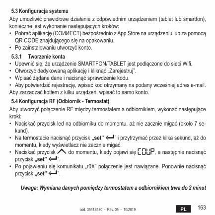
163PLcod. 3541S180 - Rev. 05 - 10/2019
5.3 KonfiguracjasystemuAbyumożliwićprawidłowedziałaniezodpowiednimurządzeniem(tabletlubsmartfon),koniecznejestwykonanienastępującychkroków:• Pobraćaplikację(COИИECT)bezpośredniozAppStorenaurządzeniulubzapomocąQRCODEznajdującegosięnaopakowaniu.
• Pozainstalowaniuutworzyćkonto.5.3.1 tworzeniekonta• Upewnićsię,żeurządzenieSMARTFON/TABLETjestpodłączonedosieciWifi.• Otworzyćdedykowanąaplikacjęikliknąć„Zarejestruj”.• Wpisaćżądanedaneinacisnąćsprawdzeniekodu.• Abypotwierdzićrejestrację,wpisaćkodotrzymanynapodanywcześniejadrese-mail.Abyzarządzaćkotłemzkilkuurządzeń,wpisaćtosamokonto.5.4 KonfiguracjarF(Odbiornik-termostat)AbyutworzyćpołączenieRFmiędzytermostatemaodbiornikiem,wykonaćnastępującekroki:• Naciskaćprzycisklednaodbiornikudomomentu,ażniezaczniemigać(około7se-
kund).• Natermostacienacisnąćprzycisk„set” ”iprzytrzymaćprzezkilkasekund,ażdomomentu,kiedywyświetlaczniezaczniemigać.
• Naciskaćprzycisk domomentu,kiedypojawisię ,anastępnienacisnąćprzycisk„set” ”.
• Popojawieniusiękomunikatu „r0X”połączenie jestnawiązane.Ponownienacisnąćprzycisk„set” ”.
Uwaga: Wymiana danych pomiędzy termostatem a odbiornikiem trwa do 2 minut
164 PL cod. 3541S180 - Rev. 05 - 10/2019
5.5 Konfiguracjawi-Fi(Odbiornik-router)PodłączyćurządzenieSmartfon/TabletdolokalnejsieciWifi.Metoda 1• Kliknąć„+”iwpisaćhasłosiecilokalnej• Nacisnąć„dalej” .• NaodbiornikuwcisnąćnachwilęprzyciskWPSzapomocąspecjalnegonarzędzia• Nacisnąć„dalej” .• Wykonaćinstrukcjezaplikacji
Jeśli procedura się nie powiodła:• SprawdzićpołączenieWifiwurządzeniumobilnym(konfiguracjapowinnabyćwyko-nanazapośrednictwemWifi)
• Sprawdzićrouter,zrestartowaćurządzeniemobilneipowtórzyćczynności(Metoda1)
Jeśli procedura wg metody 1 nie powiodła się, przeprowadzić metodę 2.Metoda 2• Otworzyćaplikacjeiwpisaćlogin• WodbiornikunacisnąćprzyciskWPS(przytrzymaćprzezconajmniej7sekund)zapomocąspecjalnegonarzędziaiodczekać,ażprzyciskledniezaczniemigaćnaczer-wono
• WybraćWifi smartfona/tabletu „Easylink_XXXXX” (ignorować komunikat o brakupodłączeniainternetowego)
• ZmienićnazwęsieciSSID„Easylink_XXXXX”nanazwęlokalnąiwpisaćhasło• Sprawdzić,czyopcjaAPjestaktywna• Nacisnąć„dalej” .• Wykonaćinstrukcjezaplikacji
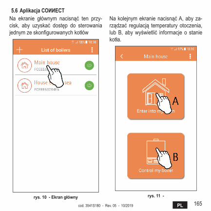
165PLcod. 3541S180 - Rev. 05 - 10/2019
5.6 aplikacjacOИИEctNa ekranie głównym nacisnąć ten przy-cisk, aby uzyskać dostęp do sterowaniajednymzeskonfigurowanychkotłów
rys. 10 -Ekrangłówny
NakolejnymekranienacisnąćA,abyza-rządzać regulacją temperatury otoczenia,lubB, abywyświetlić informacje o staniekotła.
rys. 11 -

166 PL cod. 3541S180 - Rev. 05 - 10/2019
Na tym ekranie można wpisaćnastawę podłączonego zdalne-gopanelupokojowego.
rys. 12 -Sterowaniezpanelupokojowego
Możliwetryby:
Trybręczny
Programowanie tygodniowe
Tryb wakacje
Termostatwyłączony
rys. 13 -Możliwetryby
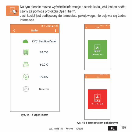
167PLcod. 3541S180 - Rev. 05 - 10/2019
Natymekraniemożnawyświetlićinformacjeostaniekotła,jeślijestonpodłą-czonyzapomocąprotokołuOpenTherm.Jeślikociołjestpodłączonydotermostatupokojowego,niepojawiasiężadnainformacja.
rys. 14 -zOpentherm
rys. 15 ztermostatempokojowym
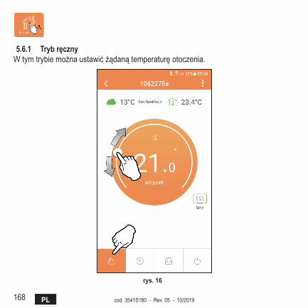
168 PL cod. 3541S180 - Rev. 05 - 10/2019
5.6.1 trybręcznyWtymtrybiemożnaustawićżądanątemperaturęotoczenia.
rys. 16

169PLcod. 3541S180 - Rev. 05 - 10/2019
5.6.2 tryb„Programowanietygodniowe”Wtymtrybiemożnaustawićżądanątemperaturęwróżnychprzedziałachgodzinowychdla wszystkich dni tygodnia.Ponaciśnięciupunktuwskazanegowrys.17.
rys. 17
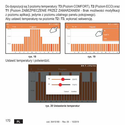
170 PL cod. 3541S180 - Rev. 05 - 10/2019
Dodyspozycjisą3poziomytemperatury:t3(PoziomCOMFORT),t2(PoziomECO)orazt1(PoziomZABEZPIECZENIEPRZEZZAMARZANIEM-Brakmożliwościmodyfikacjizpoziomuaplikacji,jedyniezpoziomuzdalnegopanelupokojowego).Abyustawićtemperaturęnapoziomiet2 i t3,wykonaćsekwencję.
rys. 18 rys. 19 Ustawićtemperaturyipotwierdzić.
rys. 20 Ustawienietemperatur
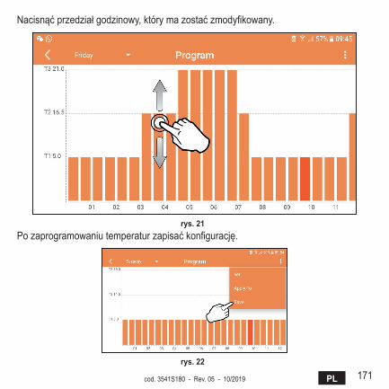
171PLcod. 3541S180 - Rev. 05 - 10/2019
Nacisnąćprzedziałgodzinowy,którymazostaćzmodyfikowany.
rys. 21 Pozaprogramowaniutemperaturzapisaćkonfigurację.
rys. 22
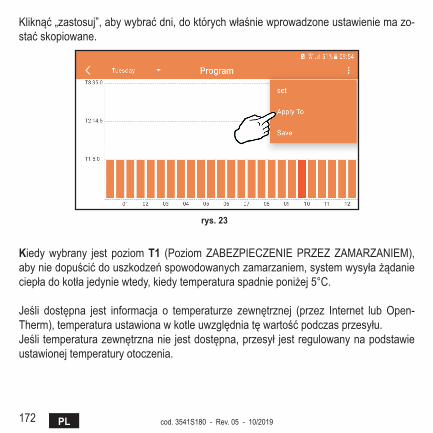
172 PL cod. 3541S180 - Rev. 05 - 10/2019
Kliknąć„zastosuj”,abywybraćdni,doktórychwłaśniewprowadzoneustawieniemazo-staćskopiowane.
rys. 23
Kiedywybrany jest poziomt1 (PoziomZABEZPIECZENIEPRZEZZAMARZANIEM),abyniedopuścićdouszkodzeńspowodowanychzamarzaniem,systemwysyłażądanieciepładokotłajedyniewtedy,kiedytemperaturaspadnieponiżej5°C.
Jeśli dostępna jest informacja o temperaturze zewnętrznej (przez Internet lub Open-Therm),temperaturaustawionawkotleuwzględniatęwartośćpodczasprzesyłu.Jeśli temperaturazewnętrznanie jestdostępna,przesył jestregulowanynapodstawieustawionejtemperaturyotoczenia.
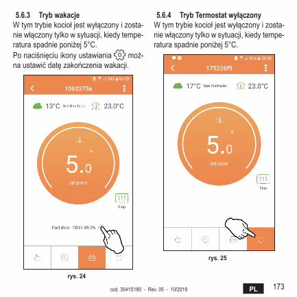
173PLcod. 3541S180 - Rev. 05 - 10/2019
5.6.3 trybwakacjeWtymtrybiekociołjestwyłączonyizosta-niewłączonytylkowsytuacji,kiedytempe-raturaspadnieponiżej5°C.Ponaciśnięciuikonyustawiania moż-naustawićdatęzakończeniawakacji.
rys. 24
5.6.4 trybtermostatwyłączonyWtymtrybiekociołjestwyłączonyizosta-niewłączonytylkowsytuacji,kiedytempe-raturaspadnieponiżej5°C.
rys. 25
174 PL cod. 3541S180 - Rev. 05 - 10/2019
5.7 termostat5.7.1 czynnościpodstawowe
1. Ponaciśnięciuprzycisku„mode” (tryb)przełączasiępomiędzyróżnymitrybami:
a. Off (Wył.):wtymtrybieżądanieciepłajestwyłączone,aktywnyjesttylkotrybzabezpieczeniaprzedzamarzaniem.
b. Vacanza (Wakacje):ustawionatemperaturatotemperaturaoszczędzaniaenergiiorazzabezpieczeniaprzedzamarzaniemobowiązującaprzezliczbędniustawionychzapomocąprzycisków .
c. automatico (Automatyczny):żądanatemperaturatotemperaturaprogramutygodniowegoustawionazapośrednictwemaplikacji.Jeśliprogramniejestusta-wiony,używanyjestdomyślnyprogramsystemu.
d. Manuale (Ręczny): temperatura jestustawiana ręczniebezpośrednionatermostacie.
2. Settemperatura(Ustawtemperaturę):a. Manuale(Ręcznie):zapomocąprzycisków .
3. Menuimpostazioni(Menuustawień):ponaciśnięciuprzycisku„set” iprzytrzy-maniuprzezok.2sekundynastępujewejściedomenuustawień.
a. „ oraz "pozwalająnaprzewijaniemenub. „set” (ustaw)pozwalanawejściedowybranegoparametruc. „mode” (tryb)umożliwiapowrótdomenugłównego
4. Wrazienieprawidłowościwdziałaniukotłanawyświetlaczutermostatupojawiasiękodbłędu.Usterkęmożnaodblokowaćzapomocąprzycisku„set” .
Abyzapoznaćsięzopisemusterki,przeczytaćinstrukcjękotła.
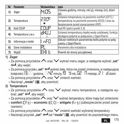
175PLcod. 3541S180 - Rev. 05 - 10/2019
Nr Parametr Wyświetlacz opis
1) Zegar Ustawia godziny, minuty, rok (y), miesiąc (m), dzień (d).
2) Temperatura Ustawia temperaturę na poziomie comfort (CFT) / temperaturę na poziomie economy (ECO) / oraz za-bezpieczenie przed zamarzaniem (FRT)
3) Kod COUP Kod RF (patrz punkt 5.3)
4) Temperatura c.w.u Ustawia temperaturę ciepłej wody użytkowej, funkcja dostępna jedynie w połączeniu z OpenTherm
5) Informacje o kotle Odczyt niektórych parametrów kotła jedynie w połą-czeniu z OpenTherm
6) Dane instalatora Parametry dla instalatora7) Wyjdź Powrót do strony początkowej
1)zegar » Zapomocąprzycisków oraz wybraćmenuzegar,anastępniewybrać„set”
,abywejść. » Zapomocąprzycisku„set” wybraćdatę,któramazostaćzmieniona,wnastępującejkolejności: godzina, minuty, rok, miesiąc, dzień.
» Zapomocąprzycisków oraz zmienićwartość. » Nacisnąć„mode” ,abypowrócić.
2)temperatura » Zapomocąprzycisków oraz wybraćmenutemperatura,anastępniewy-brać„set” ,abywejść.
» Zapomocąprzycisków oraz wybraćtemperatury,któremająbyćzmienione: » comfort ( ) – economic ( ) – antigelo ( )(zabezpieczenieprzedzama-rzaniem)
» Zapomocąprzycisków oraz zmienićwartośćwybranejtemperatury. » Nacisnąćprzycisk„set” lub “mode” ,abypowrócićdopoprzedniegomenu.
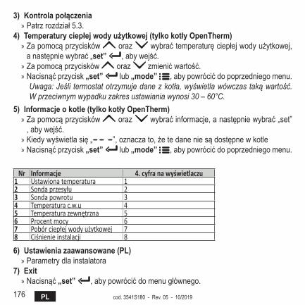
176 PL cod. 3541S180 - Rev. 05 - 10/2019
3)Kontrolapołączenia » Patrzrozdział5.3.
4)temperaturyciepłejwodyużytkowej(tylkokotłyOpentherm) » Zapomocąprzycisków oraz wybraćtemperaturęciepłejwodyużytkowej,anastępniewybrać„set” ,abywejść.
» Zapomocąprzycisków oraz zmienićwartość. » Nacisnąćprzycisk„set” lub „mode” ,abypowrócićdopoprzedniegomenu.
Uwaga: Jeśli termostat otrzymuje dane z kotła, wyświetla wówczas taką wartość. W przeciwnym wypadku zakres ustawiania wynosi 30 – 60°C.
5)informacjeokotle(tylkokotłyOpentherm) » Zapomocąprzycisków oraz wybraćinformacje,anastępniewybrać„set”,abywejść.
» Kiedywyświetlasię„ ”,oznaczato,żetedaneniesądostępnewkotle » Nacisnąćprzycisk„set” lub „mode” ,abypowrócićdopoprzedniegomenu.
Nr Informacje 4. cyfra na wyświetlaczu1 Ustawiona temperatura 12 Sonda przesyłu 23 Sonda powrotu 34 Temperatura c.w.u 45 Temperatura zewnętrzna 56 Procent mocy 67 Pobór ciepłej wody użytkowej 78 Ciśnienie instalacji 8
6)Ustawieniazaawansowane(Pl) » Parametry dla instalatora
7)Exit » Nacisnąć„set” ,abypowrócićdomenugłównego.
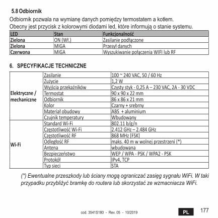
177PLcod. 3541S180 - Rev. 05 - 10/2019
5.8 OdbiornikOdbiornikpozwalanawymianędanychpomiędzytermostatemakotłem.Obecnyjestprzyciskzkolorowymidiodamiled,któreinformująostaniesystemu.LED Stan FunkcjonalnośćZielona ON (Wł.) Zasilanie podłączoneZielona MIGA Przesył danychCzerwona MIGA Wyszukiwanie połączenia WIFI lub RF
6. SPEcyFiKacjEtEchnicznE
Elektryczne / mechaniczne
Zasilanie 100 ~ 240 VAC, 50 / 60 HzZużycie 1,2 WWyjścia przekaźników Czysty styk - 0,25 A – 230 VAC, 2A - 30 VDCTermostat 90 x 90 x 22 mmOdbiornik 86 x 86 x 21 mmKolor Czarny + srebrnyMateriał obudowy ABS + aluminiumCzujnik temperatury Wbudowany
Wi-Fi
Standard Wi-Fi 802.11 b/g/nCzęstotliwość Wi-Fi 2.412 GHz – 2.484 GHzCzęstotliwość RF 868 MHz [FSK]Odległość RF maks. 40 m w wolnej przestrzeni (*) Antena wbudowanaBezpieczeństwo WEP / WPA - PSK / WPA2 - PSKProtokół IPv4, TCPTyp sieci STA
(*) Ewentualne przeszkody lub ściany mogą ograniczać zasięg sygnału WiFi. W taki przypadku przybliżyć bramkę do routera lub skorzystać ze wzmacniacza WiFi.
178 NL cod. 3541S180 - Rev. 05 - 10/2019
1. Presentatie .................................................................................................... 179
2. Algemene veiligheidsvoorschriften ........................................................... 179
3. Regelingsklasse volgens de ErP-verordening .......................................... 179
4. Voor de installateur ...................................................................................... 1804.1 Inhoud ........................................................................................................ 1804.2 Installatie van de ontvanger ....................................................................... 1814.3 Installatie van de thermostaat .................................................................... 1834.4 Montage thermostaatsteun ........................................................................ 1845. Voor de eindgebruiker ................................................................................. 1855.1 Knoppen en symbolen ............................................................................... 1855.2 Functieschema .......................................................................................... 1875.3 Systeemconfiguratie .................................................................................. 1885.3.1 Aanmaken van een account .............................................................. 1885.4 Configuratie RF (ontvanger - thermostaat) ................................................ 1885.5 Wifi-configuratie (ontvanger - router) ......................................................... 1895.6 APPCOИИECT ........................................................................................ 1905.6.1 Handbedieningsmodus ..................................................................... 1935.6.2 Modus Weekprogrammering ............................................................. 1945.6.3 Vakantiemodus .................................................................................. 1985.6.4 ModusThermostaatuit ..................................................................... 1985.7 Thermostaat............................................................................................... 1995.7.1 Basisbewerkingen ............................................................................. 1995.8 Ontvanger .................................................................................................. 2026. Technische specificaties ............................................................................. 202
179NLcod. 3541S180 - Rev. 05 - 10/2019
1. PREsEnTATiEBesteklant,wijbedankenudatugekozenheeftvoordeslimmethermostaatCOИИECT.Hiermeekuntudeomgevingstemperatuurnauwkeurigbesturen,endankzijdewifi-con-nectiviteit is bediening op afstand mogelijk via de speciale app.Deze handleiding is bedoeld voor installateurs en eindgebruikers.Het belangrijkste element van het systeem is de klokthermostaat die tijdsprogramma’s kan beheren die zijn ingesteld met de app, de zonetemperatuur kan meten en opdrach-ten voor in- en uitschakeling kan verzenden naar een externe besturingseenheid die rechtstreeks verbonden is met de ketel.
2. AlgEmEnE VEilighEidsVooRschRifTEn• Lees de instructies in deze handleiding aandachtig door.• Leg de gebruiker na de installatie de functies van het toestel uit en geef hem dit boekje,
dat zorgvuldig moet worden bewaard omdat het onderdeel is van het product en om het later nog te kunnen raadplegen
• De installatieenhetonderhoudmoetenwordenverrichtdoorervaren,gekwalificeerdpersoneel volgens de geldende voorschriften en in overeenstemming met de instructies van de fabrikant. Voer geen handelingen uit op de verzegelde besturingsonderdelen.
• Schakel de elektrische voeding uit alvorens het apparaat te reinigen.• Plaats het toestel niet in de buurt van warmtebronnen.• Houd het buiten het bereik van kinderen
3. REgElingsklAssE VolgEns dE ERP-VERoRdEningOnderverwijzingnaardegedelegeerdeverordening(EU)Nr.811/2013kunnendegegevensin de tabel worden gebruikt om de etikettering van verwarmingstoestellen te completeren.Mogelijke combinaties met COИИECT, de overeenkomende configuratieklassen enenergiebijdragen aan het systeem.
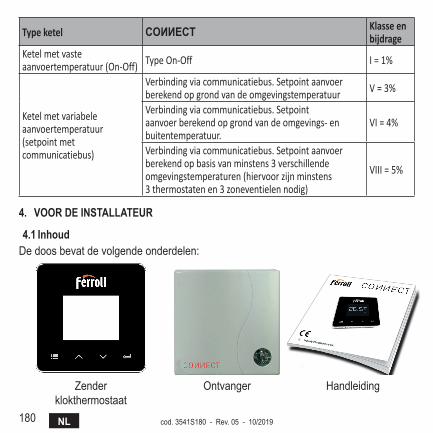
180 NL cod. 3541S180 - Rev. 05 - 10/2019
Type ketel COИИECT Klasse en bijdrage
Ketel met vaste aanvoertemperatuur (On-Off) Type On-Off I = 1%
Ketel met variabele aanvoertemperatuur (setpoint met communicatiebus)
Verbinding via communicatiebus. Setpoint aanvoer berekend op grond van de omgevingstemperatuur V = 3%
Verbinding via communicatiebus. Setpoint aanvoer berekend op grond van de omgevings- en buitentemperatuur.
VI = 4%
Verbinding via communicatiebus. Setpoint aanvoer berekend op basis van minstens 3 verschillende omgevingstemperaturen (hiervoor zijn minstens 3 thermostaten en 3 zoneventielen nodig)
VIII = 5%
4. VooR dE insTAllATEuR
4.1 inhoudDe doos bevat de volgende onderdelen:
Zenderklokthermostaat
Ontvanger Handleiding
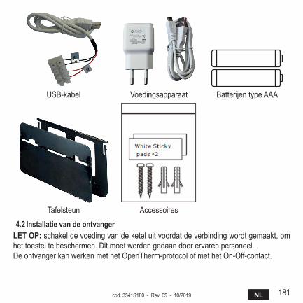
181NLcod. 3541S180 - Rev. 05 - 10/2019
USB-kabel Voedingsapparaat Batterijen type AAA
Tafelsteun Accessoires
4.2 installatie van de ontvangerlET oP: schakel de voeding van de ketel uit voordat de verbinding wordt gemaakt, om het toestel te beschermen. Dit moet worden gedaan door ervaren personeel.DeontvangerkanwerkenmethetOpenTherm-protocolofmethetOn-Off-contact.
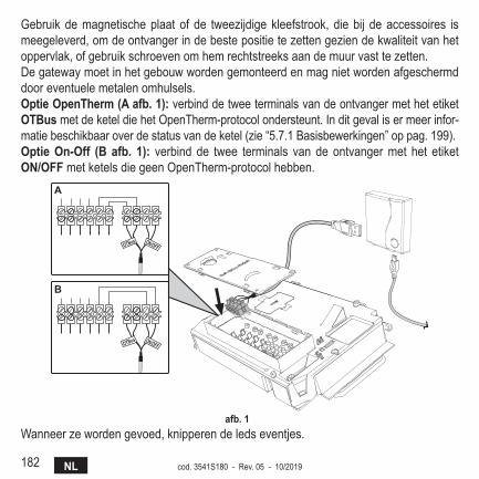
182 NL cod. 3541S180 - Rev. 05 - 10/2019
Gebruik de magnetische plaat of de tweezijdige kleefstrook, die bij de accessoires is meegeleverd, om de ontvanger in de beste positie te zetten gezien de kwaliteit van het oppervlak, of gebruik schroeven om hem rechtstreeks aan de muur vast te zetten.De gateway moet in het gebouw worden gemonteerd en mag niet worden afgeschermd door eventuele metalen omhulsels.optie openTherm (A afb. 1): verbind de twee terminals van de ontvanger met het etiket oTBusmetdeketeldiehetOpenTherm-protocolondersteunt.Inditgevalisermeerinfor-matie beschikbaar over de status van de ketel (zie “5.7.1 Basisbewerkingen” op pag. 199).optie on-off (B afb. 1): verbind de twee terminals van de ontvanger met het etiket on/offmetketelsdiegeenOpenTherm-protocolhebben.
����� ������
����� ������
�
�
afb. 1 Wanneer ze worden gevoed, knipperen de leds eventjes.
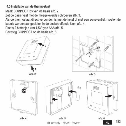
183NLcod. 3541S180 - Rev. 05 - 10/2019
4.3 installatie van de thermostaatMaakCOИИECTlosvandebasisafb.2.Zet de basis vast met de meegeleverde schroeven afb. 3.Als de thermostaat direct verbonden is met de ketel of met een zoneventiel, moeten de kabels worden aangesloten in de desbetreffende klem afb. 4.Plaats 2 batterijen van 1,5V type AAA afb. 5.BevestigCOИИECTopdebasisafb.6.
�
�
afb. 2 afb. 3
afb. 4 afb. 5 afb. 6
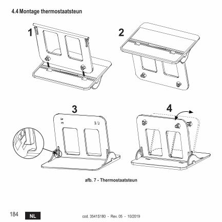
184 NL cod. 3541S180 - Rev. 05 - 10/2019
4.4 montage thermostaatsteun
7
4.3 Installazione termostatoInserire 2 batterie da 1,5V tipo AAA.4.4 Montaggio supporto termostato
� �
� �
fig. 2 - afb. 7 - Thermostaatsteun
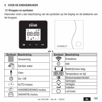
185NLcod. 3541S180 - Rev. 05 - 10/2019
5. VooR dE EindgEBRuikER
5.1 knoppen en symbolenHieronder vindt u een beschrijving van de symbolen op het display en de betekenis van de knoppen.
afb. 8 symbool Beschrijving
Verwarming
Sanitair water
Vlam
On / Off
AUTO-modus
HANDBEDIENING-modusVAKANTIE-modus
symbool BeschrijvingDraadloos
Wifi
Batterijniveau laag
TemperatuurentijdModus/opslaan/sluitenVerhogenVerlagenInstellenLed-toets
186 NL cod. 3541S180 - Rev. 05 - 10/2019
Batterij: Als de batterijlading onvoldoende is, verschijnt het symbool op het scherm.Vlam
» Thermostaat verbondenmet een on-off-ketel, het symbool geeft de staat van devraag aan.
» ThermostaatverbondenmeteenOpenTherm-ketel,hetsymboolgeeftdestaatvande brander aan.Opmerkingen: bij de eerste inschakeling wordt de thermostaat automatisch gecon-figureerd in de verbindingsmodus met draad, On-Off.Als de thermostaat en de wifi-ontvanger draadloos zijn verbonden schakelt de ther-mostaat automatisch over naar de modus RF On-Off.Als de wifi-ontvanger verbonden is met een OpenTherm-ketel, schakelt de thermo-staat automatisch over naar de modus RF OpenTherm.Als de thermostaat geconfigureerd is als RF (on-off of OpenTherm) schakelt hij niet automatisch over naar de modus draad on-off. Dit kan alleen worden gedaan door de batterijen te verwijderen en terug te plaatsen.
sanitair: in de handbediening- of automatische modus geeft dit symbool aan dat het sanitaire water actief is.
Opmerkingen: het symbool is alleen aanwezig bij een RF-verbinding met Open-Therm-ketels.
Verwarming: het symbool geeft aan dat de verwarming actief is.Opmerkingen: het symbool is alleen aanwezig bij een RF-verbinding met Open-Therm-ketels.
Temperatuur: de omgevingstemperatuur of de fouten worden weergegeven:E82: RF-communicatiefoutE83: OpenTherm-communicatiefout
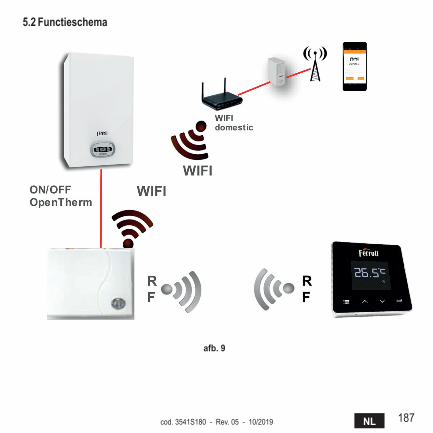
187NLcod. 3541S180 - Rev. 05 - 10/2019
5.2 functieschema
afb. 9
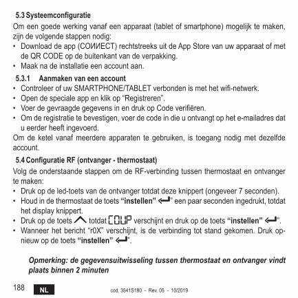
188 NL cod. 3541S180 - Rev. 05 - 10/2019
5.3 systeemconfiguratieOm een goede werking vanaf een apparaat (tablet of smartphone) mogelijk te maken, zijn de volgende stappen nodig:• Downloaddeapp(COИИECT)rechtstreeksuitdeAppStorevanuwapparaatofmetdeQRCODEopdebuitenkantvandeverpakking.
• Maak na de installatie een account aan.5.3.1 Aanmaken van een account• ControleerofuwSMARTPHONE/TABLETverbondenismethetwifi-netwerk.• Open de speciale app en klik op “Registreren”.• VoerdegevraagdegegevensinendrukopCodeverifiëren.• Om de registratie te bevestigen, voer de code in die u ontvangt op het e-mailadres dat
u eerder heeft ingevoerd.Om de ketel vanaf meerdere apparaten te gebruiken, is toegang nodig met dezelfde account.5.4 configuratie Rf (ontvanger - thermostaat)
Volg de onderstaande stappen om de RF-verbinding tussen thermostaat en ontvanger te maken:• Druk op de led-toets van de ontvanger totdat deze knippert (ongeveer 7 seconden).• Houd in de thermostaat de toets “instellen” ” een paar seconden ingedrukt, totdat
het display knippert.• Druk op de toets totdat verschijnt en druk op de toets “instellen” ”.• Wanneer het bericht “r0X” verschijnt, is de verbinding tot stand gekomen. Druk op-
nieuw op de toets “instellen” ”.
Opmerking: de gegevensuitwisseling tussen thermostaat en ontvanger vindt plaats binnen 2 minuten
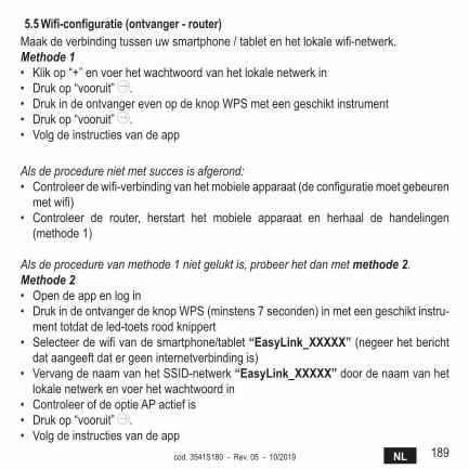
189NLcod. 3541S180 - Rev. 05 - 10/2019
5.5 Wifi-configuratie (ontvanger - router)Maakdeverbindingtussenuwsmartphone/tabletenhetlokalewifi-netwerk.Methode 1• Klik op “+” en voer het wachtwoord van het lokale netwerk in• Druk op “vooruit” .• Druk in de ontvanger even op de knop WPS met een geschikt instrument• Druk op “vooruit” .• Volg de instructies van de app
Als de procedure niet met succes is afgerond:• Controleerdewifi-verbindingvanhetmobieleapparaat(deconfiguratiemoetgebeurenmetwifi)
• Controleer de router, herstart het mobiele apparaat en herhaal de handelingen (methode 1)
Als de procedure van methode 1 niet gelukt is, probeer het dan met methode 2.Methode 2• Open de app en log in• Druk in de ontvanger de knop WPS (minstens 7 seconden) in met een geschikt instru-
ment totdat de led-toets rood knippert• Selecteerdewifivandesmartphone/tablet“Easylink_XXXXX” (negeer het bericht
dat aangeeft dat er geen internetverbinding is)• Vervang de naam van het SSID-netwerk “Easylink_XXXXX” door de naam van het
lokale netwerk en voer het wachtwoord in• Controleer of de optie AP actief is• Druk op “vooruit” .• Volg de instructies van de app
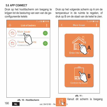
190 NL cod. 3541S180 - Rev. 05 - 10/2019
5.6 APP COИИECTDruk op het hoofdscherm om toegang te krijgen tot de besturing van een van de ge-configureerdeketels
afb. 10 - hoofdscherm
Druk op het volgende scherm op A om de temperatuur in de ruimte te regelen, of druk op B om de staat van de ketel te zien.
afb. 11 - Vanuit dit scherm is toegang
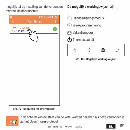
191NLcod. 3541S180 - Rev. 05 - 10/2019
mogelijk tot de instelling van de verbonden externe klokthermostaat.
afb. 12 - Besturing klokthermostaat
de mogelijke werkingswijzen zijn:
Handbedieningsmodus
Weekprogrammering
Vakantiemodus
Thermostaatuit
afb. 13 - mogelijke werkingswijzen
In dit scherm kan de staat van de ketel worden bekeken als deze verbonden is viahetOpenTherm-protocol.
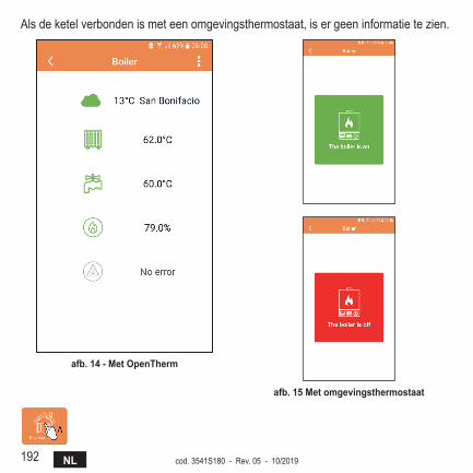
192 NL cod. 3541S180 - Rev. 05 - 10/2019
Als de ketel verbonden is met een omgevingsthermostaat, is er geen informatie te zien.
afb. 14 - met openTherm
afb. 15 met omgevingsthermostaat
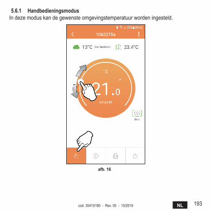
193NLcod. 3541S180 - Rev. 05 - 10/2019
5.6.1 handbedieningsmodusIn deze modus kan de gewenste omgevingstemperatuur worden ingesteld.
afb. 16
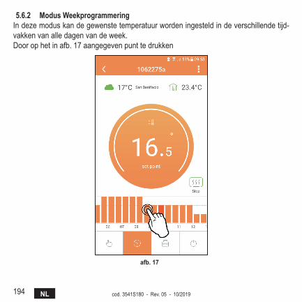
194 NL cod. 3541S180 - Rev. 05 - 10/2019
5.6.2 modus WeekprogrammeringIn deze modus kan de gewenste temperatuur worden ingesteld in de verschillende tijd-vakken van alle dagen van de week.Door op het in afb. 17 aangegeven punt te drukken
afb. 17
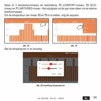
195NLcod. 3541S180 - Rev. 05 - 10/2019
Staan er 3 temperatuurniveaus ter beschikking: T3 (COMFORT-niveau), T2 (ECO-niveau) en T1(ANTIVRIES-niveau-Nietwijzigbaarviadeappmaaralleenviadeexterneklokthermostaat).Om de temperatuur van niveau T2 en T3 in te stellen, volg de sequens.
afb. 18 afb. 19 Stel de temperaturen in en bevestig.
afb. 20 instelling temperaturen

196 NL cod. 3541S180 - Rev. 05 - 10/2019
Druk in het tijdvak dat u wilt wijzigen.
afb. 21 Sladeconfiguratieop,nadatdetemperaturenzijngeprogrammeerd.
afb. 22
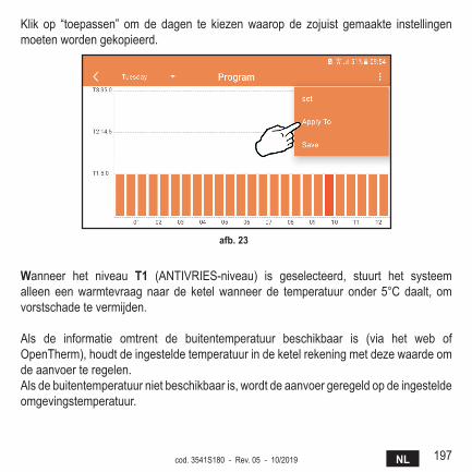
197NLcod. 3541S180 - Rev. 05 - 10/2019
Klik op “toepassen” om de dagen te kiezen waarop de zojuist gemaakte instellingen moeten worden gekopieerd.
afb. 23
Wanneer het niveau T1 (ANTIVRIES-niveau) is geselecteerd, stuurt het systeemalleen een warmtevraag naar de ketel wanneer de temperatuur onder 5°C daalt, om vorstschade te vermijden.
Als de informatie omtrent de buitentemperatuur beschikbaar is (via het web of OpenTherm),houdtdeingesteldetemperatuurindeketelrekeningmetdezewaardeomde aanvoer te regelen.Als de buitentemperatuur niet beschikbaar is, wordt de aanvoer geregeld op de ingestelde omgevingstemperatuur.
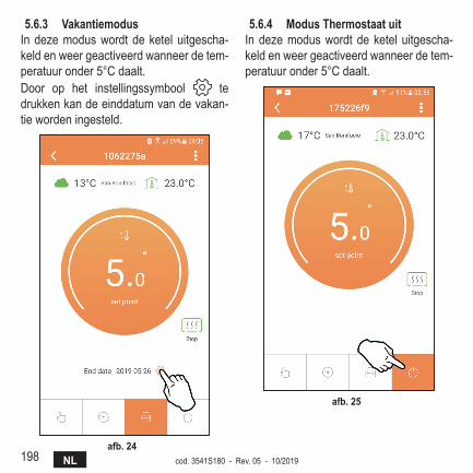
198 NL cod. 3541S180 - Rev. 05 - 10/2019
5.6.3 VakantiemodusIn deze modus wordt de ketel uitgescha-keld en weer geactiveerd wanneer de tem-peratuur onder 5°C daalt.Door op het instellingssymbool te drukken kan de einddatum van de vakan-tie worden ingesteld.
afb. 24
5.6.4 modus Thermostaat uitIn deze modus wordt de ketel uitgescha-keld en weer geactiveerd wanneer de tem-peratuur onder 5°C daalt.
afb. 25
199NLcod. 3541S180 - Rev. 05 - 10/2019
5.7 Thermostaat5.7.1 Basisbewerkingen
1. Door op de toets “mode” te drukken wordt afgewisseld tussen de verschillende modi:
a. off : in deze modus is de warmtevraag uitgeschakeld, alleen de antivriesfunc-tie blijft actief.
b. Vakantie : de ingestelde temperatuur is die van de antivries-energiebespa-ring voor een aantal dagen dat is ingesteld met de toetsen .
c. Automatisch : de gevraagde temperatuur is die van het weekprogramma dat is ingesteld met de app. Als het programma niet is ingesteld, wordt het standaard-programma van het systeem gebruikt.
d. handbediening : de temperatuur wordt handmatig ingesteld, rechtstreeks op de thermostaat.
2. Temperatuur instellen:a. handbediening: gebruik de toetsen .
3. menu instellingen: door de toets “instellen” ongeveer 2 seconden ingedrukt te houden wordt het menu Instellingen geopend.
a. “ en ” om door het menu te schuivenb. “instellen” de geselecteerde parameter wordt geopendc. “modus” voor terugkeer naar het hoofdmenu
4. Bij een storing in de ketel wordt de foutcode ook weergegeven op het display van de thermostaat. De storing kan worden ontgrendeld met de toets “instellen” .
Voor een beschrijving van de storing, zie het boekje van de ketel.
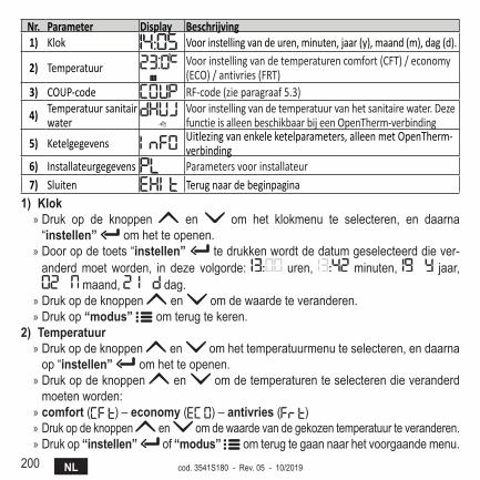
200 NL cod. 3541S180 - Rev. 05 - 10/2019
Nr. Parameter Display Beschrijving1) Klok Voor instelling van de uren, minuten, jaar (y), maand (m), dag (d).
2) Temperatuur Voor instelling van de temperaturen comfort (CFT) / economy (ECO) / antivries (FRT)
3) COUP-code RF-code (zie paragraaf 5.3)
4) Temperatuur sanitair water
Voor instelling van de temperatuur van het sanitaire water. Deze functie is alleen beschikbaar bij een OpenTherm-verbinding
5) Ketelgegevens Uitlezing van enkele ketelparameters, alleen met OpenTherm-verbinding
6) Installateurgegevens Parameters voor installateur7) Sluiten Terug naar de beginpagina
1) klok » Druk op de knoppen en om het klokmenu te selecteren, en daarna “instellen” om het te openen.
» Door op de toets “instellen” te drukken wordt de datum geselecteerd die ver-anderd moet worden, in deze volgorde: uren, minuten, jaar,
maand, dag. » Druk op de knoppen en om de waarde te veranderen. » Druk op “modus” om terug te keren.
2) Temperatuur » Druk op de knoppen en om het temperatuurmenu te selecteren, en daarna op “instellen” om het te openen.
» Druk op de knoppen en om de temperaturen te selecteren die veranderd moeten worden:
» comfort ( ) – economy ( ) – antivries ( ) » Druk op de knoppen en om de waarde van de gekozen temperatuur te veranderen. » Druk op “instellen” of “modus” om terug te gaan naar het voorgaande menu.

201NLcod. 3541S180 - Rev. 05 - 10/2019
3) koppelingscode » Zie paragraaf 5.3.
4) Temperaturen sanitair water (alleen openTherm-ketels) » Druk op de knoppen om het temperatuurmenu van het sanitaire water te selecteren, en daarna “instellen” om het te openen.
» Druk op de knoppen om de waarde te veranderen. » Druk op “instellen” of “modus” om terug te gaan naar het voorgaande menu.
Opmerking: als de thermostaat het gegeven ontvangt van de ketel, geeft hij deze waarde weer, anders is het instellingsbereik 30 – 60°C.
5) informatie van de ketel (alleen openTherm-ketels) » Druk op de knoppen om gegevens te selecteren, en daarna op “instellen” om ze te openen.
» Wanneer “ ” wordt weergegeven, is de datum niet beschikbaar in de boiler » Druk op “instellen” of “modus” om terug te gaan naar het voorgaande menu.
Nr. Informatie 4e cijfer op display1 Instelde temperatuur 12 Aanvoersonde 23 Retoursonde 34 Temperatuur sanitair water 45 Buitentemperatuur 56 Vermogenspercentage 67 Opname sanitair water 78 Druk installatie 8
6) geavanceerde instellingen (Pl) » Parameters voor installateur
7) Exit » Druk op “instellen” om terug te gaan naar het hoofdmenu.
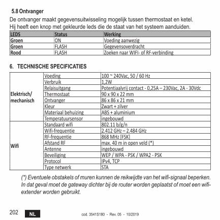
202 NL cod. 3541S180 - Rev. 05 - 10/2019
5.8 ontvangerDe ontvanger maakt gegevensuitwisseling mogelijk tussen thermostaat en ketel.Hij heeft een knop met gekleurde leds die de staat van het systeem aanduiden.LEDS Status WerkingGroen ON Voeding aanwezigGroen FLASH GegevensoverdrachtRood FLASH Zoeken naar WIFI- of RF-verbinding
6. TEchnischE sPEcificATiEs
Elektrisch/mechanisch
Voeding 100 ~ 240Vac, 50 / 60 HzVerbruik 1,2WRelaisuitgang Potentiaalvrij contact - 0,25A – 230Vac, 2A - 30VdcThermostaat 90 x 90 x 22 mmOntvanger 86 x 86 x 21 mmKleur Zwart + zilverMateriaal behuizing ABS + aluminiumTemperatuursensor ingebouwd
Wifi
Standaard wifi 802.11 b/g/nWifi-frequentie 2.412 GHz – 2.484 GHzRF-frequentie 868 MHz [FSK]Afstand RF max. 40 m in open veld (*) Antenne ingebouwdBeveiliging WEP / WPA - PSK / WPA2 - PSKProtocol IPv4, TCPType netwerk STA
(*) Eventuele obstakels of muren kunnen de reikwijdte van het wifi-signaal beperken. In dat geval moet de gateway dichter bij de router worden geplaatst of moet een wifi-extender worden gebruikt.


Via
Fabbricato in Cina - Made in China - Fabricado en ChinaFabriqué en Chine - Fabricat în China - Сделано в Китае
Wyprodukowano w Chinach - Vervaardigd in China