C182 Checklist
22
Cessna 182S-CHECKLIST PROCEDURES PREFLIGHT INSPECTION ‹ CABIN 1. Pitot Tube Cover -- REMOVE (if installed) and check for stoppage 2. Pilot’s Operating Handbook – AVAILABLE IN THE AIRPLANE 3. Airplane Weight and Balance – CHECKED 4. Parking Brake – SET 5. Control Wheel Lock – REMOVE 6. Ignition Switch – OFF 7. Avionics Power Switch – OFF WARNING WHEN TURNING ON THE MASTER SWITCH, USING AN EXTERNAL POWER SOURCE, OR PULLING THE PROPELLER THROUGH BY HAND, TREAT THE PROPELLER AS IF THE IGNITION SWITCH WERE ON. DO NOT STAND, NOR ALLOW ANYONE ELSE TO STAND, WITHIN THE ARC OF THE PROPELLER, SINCE A LOOSE OR BROKEN WIRE OR A COMPONENT MALFUNCTION COULD CAUSE THE PROPELLER TO ROTATE. 8. Master Switch – ON 9. Fuel quantity Indicators – CHECK QUANTITY ( L Low Fuel R) and ENSURE LOW FUEL ANNUNCIATORS ARE EXTINGUISHED 10. Avionics Master Switch – ON 11. Avionics Cooling Fan – CHECK AUDIBLY FOR OPERATION 12. Avionics Master Switch – OFF 13. Static Pressure Alternate Source Valve – OFF 14. Annunciator Panel Switch – PLACE AND HOLD IN TST POSITION and ensure all annunciators illuminate
-
Upload
michael-linn -
Category
Documents
-
view
18 -
download
1
description
C182 Checklist
Transcript of C182 Checklist
Cessna 182S-CHECKLIST PROCEDURES
PREFLIGHT INSPECTION
¬ CABIN
1. Pitot Tube Cover -- REMOVE (if installed) and check forstoppage
2. Pilot’s Operating Handbook – AVAILABLE IN THE AIRPLANE3. Airplane Weight and Balance – CHECKED4. Parking Brake – SET5. Control Wheel Lock – REMOVE6. Ignition Switch – OFF7. Avionics Power Switch – OFF
ssWARNING
WHEN TURNING ON THE MASTER SWITCH, USING AN EXTERNAL POWER SOURCE, OR PULLING THE PROPELLER THROUGH BY HAND, TREAT THE PROPELLER AS IF THE IGNITION SWITCH WERE ON. DO NOT STAND, NOR ALLOW ANYONE ELSE TO STAND, WITHIN THE ARC OF THE PROPELLER, SINCE A LOOSE OR BROKEN WIRE OR A COMPONENT MALFUNCTION COULD CAUSE THE PROPELLER TO ROTATE.
8. Master Switch – ON9. Fuel quantity Indicators – CHECK QUANTITY ( L Low Fuel R)
and ENSURE LOW FUEL ANNUNCIATORS AREEXTINGUISHED
10. Avionics Master Switch – ON11. Avionics Cooling Fan – CHECK AUDIBLY FOR OPERATION12. Avionics Master Switch – OFF13. Static Pressure Alternate Source Valve – OFF14. Annunciator Panel Switch – PLACE AND HOLD IN TST
POSITION and ensure all annunciators illuminate
15. Annunciator Panel Test Switch – RELEASE Check thatappropriate annunciators remain on.
NOTE
When Master Switch is turned ON, some annunciators willflash for approximately 10 seconds before illuminatingsteadily. When panel TST switch is toggled up and held inposition, all remaining lights will flash until the switch is released
16. Fuel Selector Valve – BOTH17. Flaps – EXTEND18. Pitot Heat – ON (check that pitot heater is warm to the touch
within 30 seconds with battery and pitot switches on)19. Pitot Heat – OFF20. Master Switch – OFF21. Baggage door – CHECK (lock with key)
EMPENNAGE
1. Rudder Gust Lock – REMOVE2. Tail Tie Down – DISCONNECT3. Control Surfaces – Freedom of movement and
Security4. Trim Tab – CHECK Security5. Antennas – CHECK for security of attachment and general
condition
® RIGHT WING Trailing Edge
1. Aileron – CHECK freedom of movement and security2. Flap – CHECK for security and condition
¯ RIGHT WING
1. Wing Tie Down – DISCONNECT2. Fuel Tank Vent Opening – CHECK for Stoppage3. Main Wheel Tire – CHECK for proper inflation and generalcondition (weather checks, tread depth and wear)
ssWARNING
IF, AFTER REPEATED SMAPLING, EVIDENCE OFCONTANIMATION STILL EXISTS, THE AIRPLANESHOULD NOT BE FLOWN. TANKS SHOULD BEDRAINED AND SYSTEM PURGED BY QUALIFIEDMAINTENANCE PERSONNEL. ALL EVIDENCE OFCONTAMINATION MUST BE REMOVED BEFOREFURTHER FLIGHT.
4. Fuel Tank Sump Quick Drain Valves -- DRAIN at least acupful of fuel (using sampler cup) from each sump location tocheck for water, sediment, and proper fuel grade before eachflight and after each refueling. If water is observed, takefurther samples until clear and then gently rock wings andlower tail to the ground to move any additional contaminantsto the sampling points. Take repeated samples from all fueldrain points until all contamination has been removed. Ifcontaminants are still present, refer to above WARNING anddo not fly airplane
5. Fuel Quantity – CHECK VISUALLY for desired level6. Fuel Filler Cap – SECURE and VENT UNOBSTRUCTED
° NOSE
1. Static Source opening (right side of fuselage) – Check forblockage
2. Fuel Strainer Quick Drain Valve (Located on bottom offuselage) – DRAIN at least a cupful of fuel (using samplercup) from valve to check for water, sediment, and proper fuelgrade before each flight and after each refueling. If water isobserved, take further samples until clear and then gently rockwings and lower tail to the ground to move any additionalcontaminants to the sampling points. Take repeated samplesfrom all fuel drain points until all contamination has beenremoved
3. Reservoir Quick Drain Valve and Fuel Selector Quick DrainValve -- DRAIN at least a cupful of fuel (using sampler cup)from valve to check for water, sediment, and proper fuel gradebefore each flight and after each refueling. If water is
observed, take further samples until clear and then gently rockwings and lower tail to the ground to move any additionalcontaminants to the sampling points. Take repeated samplesfrom all fuel drain points until all contamination has beenremoved
4. Engine Oil Dipstick/Filler Cap – CHECK oil level, then checkdipstick/filler cap SECURE. Do not operate with less than fourquarts. Fill to nine quarts for extended flight
5. Engine Cooling Air Inlets – CLEAR of obstructions6. Propeller and Spinner – CHECK for nicks and security7. Air Filter – CHECK for restrictions by dust or other foreign
matter8. Nose Wheel Strut and Tire – CHECK for proper inflation of
strut and general condition (weather checks, tread depth andwear of tire)
9. Left Static Source Opening – CHECK for stoppage
± LEFT WING
1. Fuel Quantity – CHECK VISUALLY for desired level2. Fuel Filler Cap – SECURE and VENT UNOBSTRUCTED3. Fuel Tank Sump Quick Drain Valves -- DRAIN at least a
cupful of fuel (using sampler cup) from each sump location tocheck for water, sediment, and proper fuel grade before eachflight and after each refueling. If water is observed, takefurther samples until clear and then gently rock wings andlower tail to the ground to move any additional contaminantsto the sampling points. Take repeated samples from all fueldrain points until all contamination has been removed. Ifcontaminants are still present, refer to WARNING on page 4-9and do not fly airplane
4. Main Wheel Tire – CHECK for proper inflation and generalcondition (weather checks, tread depth and wear)
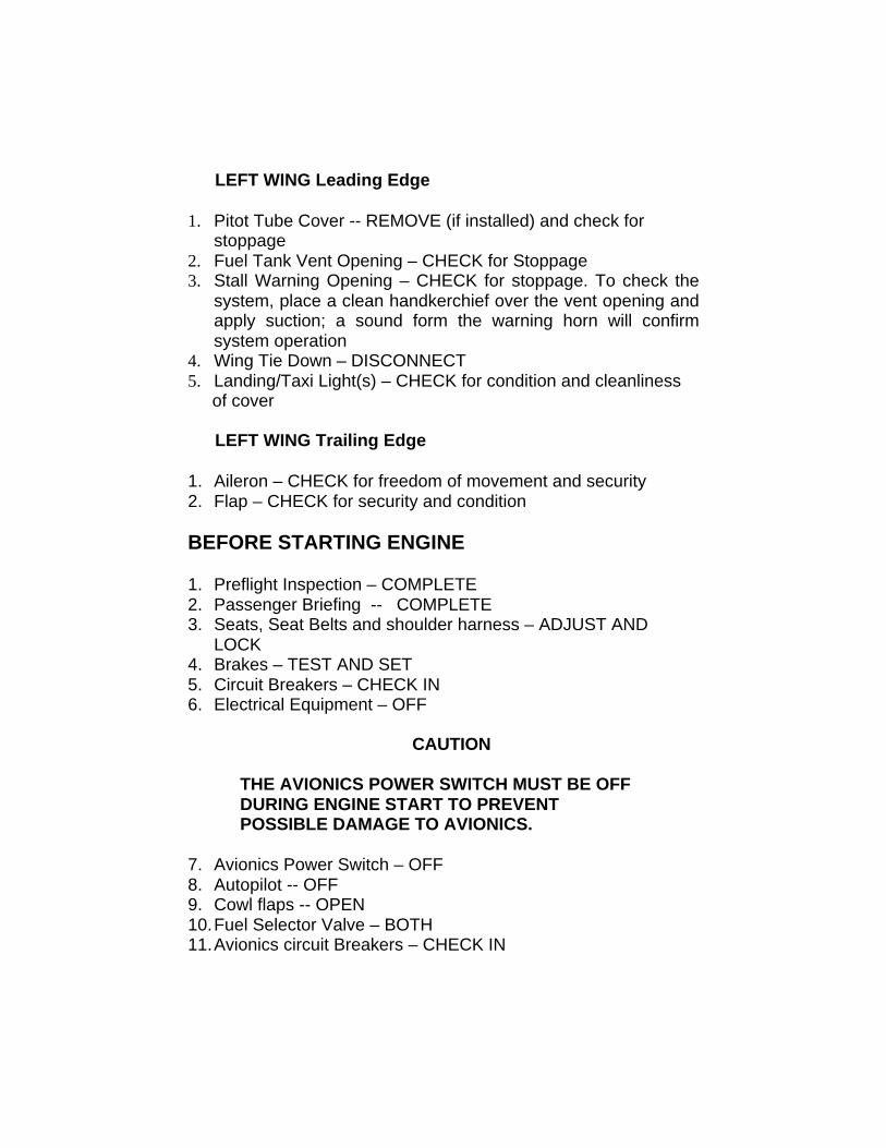
² LEFT WING Leading Edge
1. Pitot Tube Cover -- REMOVE (if installed) and check forstoppage
2. Fuel Tank Vent Opening – CHECK for Stoppage3. Stall Warning Opening – CHECK for stoppage. To check the
system, place a clean handkerchief over the vent opening andapply suction; a sound form the warning horn will confirmsystem operation
4. Wing Tie Down – DISCONNECT5. Landing/Taxi Light(s) – CHECK for condition and cleanliness of cover
³ LEFT WING Trailing Edge
1. Aileron – CHECK for freedom of movement and security2. Flap – CHECK for security and condition
BEFORE STARTING ENGINE
1. Preflight Inspection – COMPLETE2. Passenger Briefing -- COMPLETE3. Seats, Seat Belts and shoulder harness – ADJUST AND
LOCK4. Brakes – TEST AND SET5. Circuit Breakers – CHECK IN6. Electrical Equipment – OFF
ssCAUTION
THE AVIONICS POWER SWITCH MUST BE OFFDURING ENGINE START TO PREVENTPOSSIBLE DAMAGE TO AVIONICS.
7. Avionics Power Switch – OFF8. Autopilot -- OFF9. Cowl flaps -- OPEN10. Fuel Selector Valve – BOTH11. Avionics circuit Breakers – CHECK IN
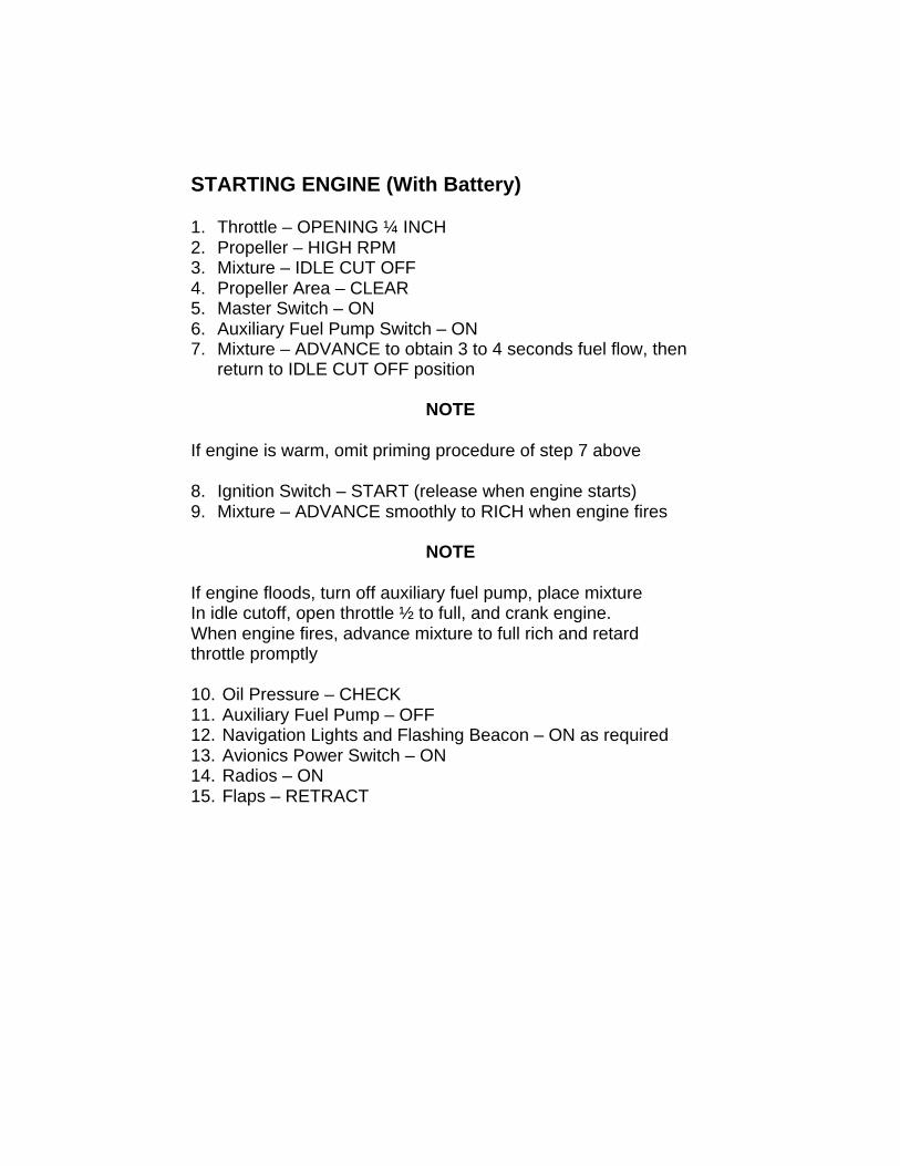
STARTING ENGINE (With Battery)
1. Throttle – OPENING ¼ INCH2. Propeller – HIGH RPM3. Mixture – IDLE CUT OFF4. Propeller Area – CLEAR5. Master Switch – ON6. Auxiliary Fuel Pump Switch – ON7. Mixture – ADVANCE to obtain 3 to 4 seconds fuel flow, then
return to IDLE CUT OFF position
NOTE
If engine is warm, omit priming procedure of step 7 above
8. Ignition Switch – START (release when engine starts)9. Mixture – ADVANCE smoothly to RICH when engine fires
NOTE
If engine floods, turn off auxiliary fuel pump, place mixtureIn idle cutoff, open throttle ½ to full, and crank engine.When engine fires, advance mixture to full rich and retardthrottle promptly
10. Oil Pressure – CHECK11. Auxiliary Fuel Pump – OFF12. Navigation Lights and Flashing Beacon – ON as required13. Avionics Power Switch – ON14. Radios – ON15. Flaps – RETRACT
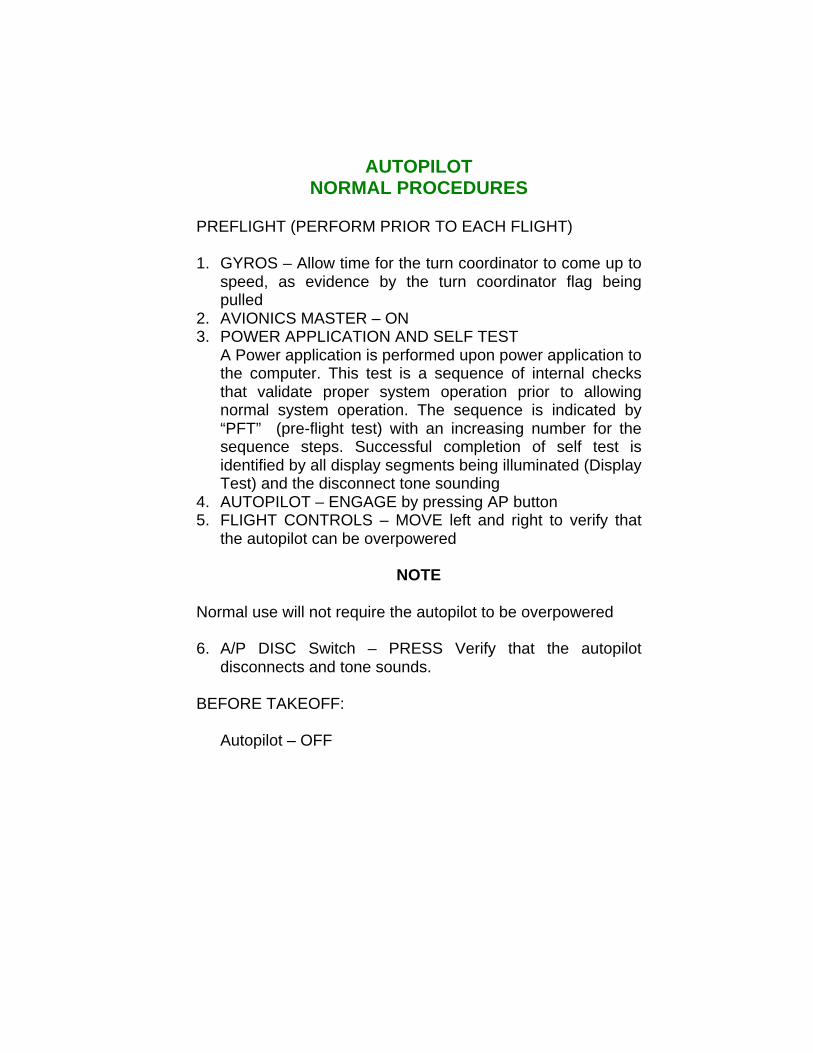
AUTOPILOTNORMAL PROCEDURES
PREFLIGHT (PERFORM PRIOR TO EACH FLIGHT)
1. GYROS – Allow time for the turn coordinator to come up tospeed, as evidence by the turn coordinator flag beingpulled
2. AVIONICS MASTER – ON3. POWER APPLICATION AND SELF TEST
A Power application is performed upon power application tothe computer. This test is a sequence of internal checksthat validate proper system operation prior to allowingnormal system operation. The sequence is indicated by“PFT” (pre-flight test) with an increasing number for thesequence steps. Successful completion of self test isidentified by all display segments being illuminated (DisplayTest) and the disconnect tone sounding
4. AUTOPILOT – ENGAGE by pressing AP button5. FLIGHT CONTROLS – MOVE left and right to verify that
the autopilot can be overpowered
NOTE
Normal use will not require the autopilot to be overpowered
6. A/P DISC Switch – PRESS Verify that the autopilotdisconnects and tone sounds.
BEFORE TAKEOFF:
Autopilot – OFF
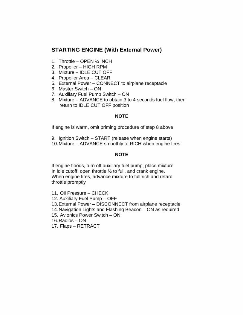
STARTING ENGINE (With External Power)
1. Throttle – OPEN ¼ INCH2. Propeller – HIGH RPM3. Mixture – IDLE CUT OFF4. Propeller Area – CLEAR5. External Power – CONNECT to airplane receptacle6. Master Switch – ON7. Auxiliary Fuel Pump Switch – ON8. Mixture – ADVANCE to obtain 3 to 4 seconds fuel flow, then return to IDLE CUT OFF position
NOTE
If engine is warm, omit priming procedure of step 8 above
9. Ignition Switch – START (release when engine starts)10. Mixture – ADVANCE smoothly to RICH when engine fires
NOTE
If engine floods, turn off auxiliary fuel pump, place mixtureIn idle cutoff, open throttle ½ to full, and crank engine.When engine fires, advance mixture to full rich and retardthrottle promptly
11. Oil Pressure – CHECK12. Auxiliary Fuel Pump – OFF13. External Power – DISCONNECT from airplane receptacle14. Navigation Lights and Flashing Beacon – ON as required15. Avionics Power Switch – ON16. Radios – ON17. Flaps – RETRACT
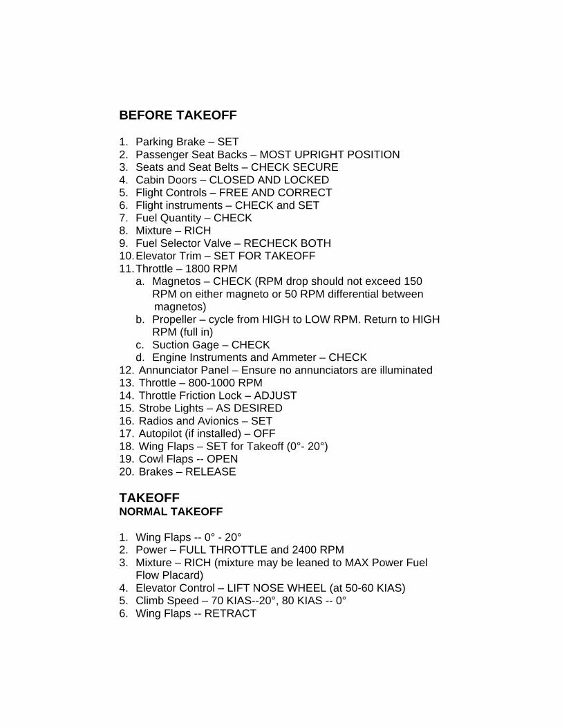
BEFORE TAKEOFF
1. Parking Brake – SET2. Passenger Seat Backs – MOST UPRIGHT POSITION3. Seats and Seat Belts – CHECK SECURE4. Cabin Doors – CLOSED AND LOCKED5. Flight Controls – FREE AND CORRECT6. Flight instruments – CHECK and SET7. Fuel Quantity – CHECK8. Mixture – RICH9. Fuel Selector Valve – RECHECK BOTH10. Elevator Trim – SET FOR TAKEOFF11. Throttle – 1800 RPM
a. Magnetos – CHECK (RPM drop should not exceed 150RPM on either magneto or 50 RPM differential between
magnetos)b. Propeller – cycle from HIGH to LOW RPM. Return to HIGH
RPM (full in)c. Suction Gage – CHECKd. Engine Instruments and Ammeter – CHECK
12. Annunciator Panel – Ensure no annunciators are illuminated13. Throttle – 800-1000 RPM14. Throttle Friction Lock – ADJUST15. Strobe Lights – AS DESIRED16. Radios and Avionics – SET17. Autopilot (if installed) – OFF18. Wing Flaps – SET for Takeoff (0°- 20°)19. Cowl Flaps -- OPEN20. Brakes – RELEASE
TAKEOFFNORMAL TAKEOFF
1. Wing Flaps -- 0° - 20°2. Power – FULL THROTTLE and 2400 RPM3. Mixture – RICH (mixture may be leaned to MAX Power Fuel
Flow Placard)4. Elevator Control – LIFT NOSE WHEEL (at 50-60 KIAS)5. Climb Speed – 70 KIAS--20°, 80 KIAS -- 0°6. Wing Flaps -- RETRACT
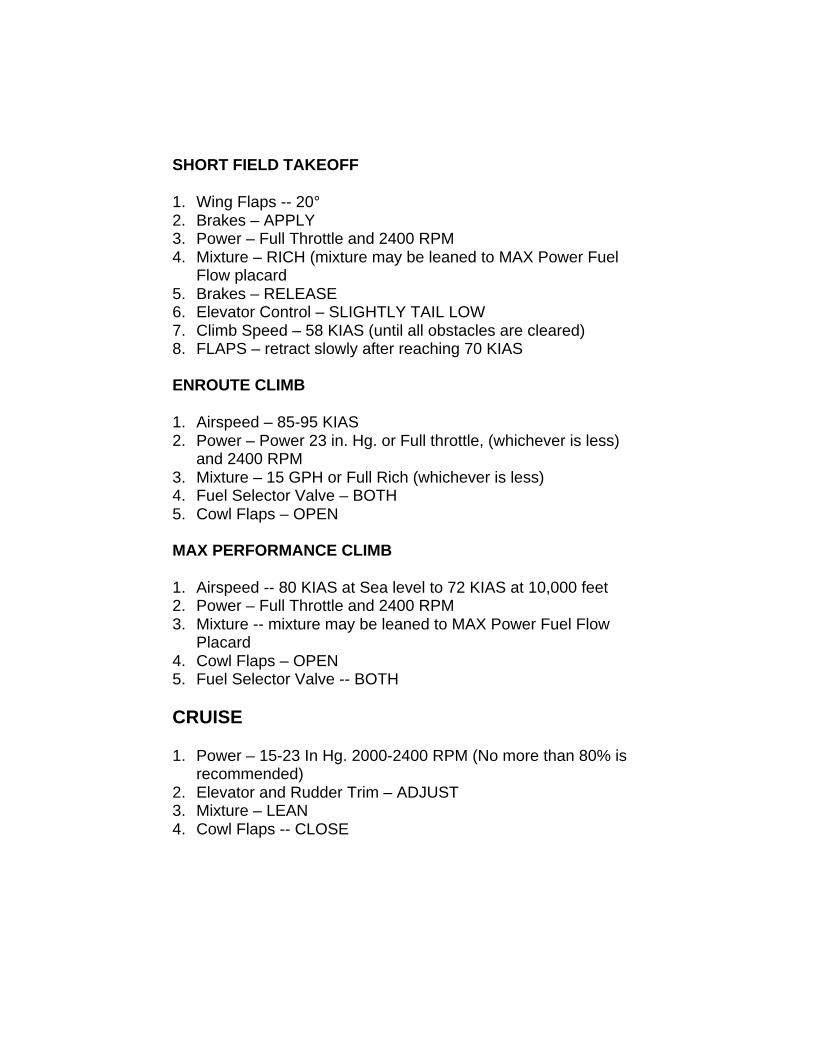
SHORT FIELD TAKEOFF
1. Wing Flaps -- 20°2. Brakes – APPLY3. Power – Full Throttle and 2400 RPM4. Mixture – RICH (mixture may be leaned to MAX Power Fuel
Flow placard5. Brakes – RELEASE6. Elevator Control – SLIGHTLY TAIL LOW7. Climb Speed – 58 KIAS (until all obstacles are cleared)8. FLAPS – retract slowly after reaching 70 KIAS
ENROUTE CLIMB
1. Airspeed – 85-95 KIAS2. Power – Power 23 in. Hg. or Full throttle, (whichever is less)
and 2400 RPM3. Mixture – 15 GPH or Full Rich (whichever is less)4. Fuel Selector Valve – BOTH5. Cowl Flaps – OPEN
MAX PERFORMANCE CLIMB
1. Airspeed -- 80 KIAS at Sea level to 72 KIAS at 10,000 feet2. Power – Full Throttle and 2400 RPM3. Mixture -- mixture may be leaned to MAX Power Fuel Flow
Placard4. Cowl Flaps – OPEN5. Fuel Selector Valve -- BOTH
CRUISE
1. Power – 15-23 In Hg. 2000-2400 RPM (No more than 80% isrecommended)
2. Elevator and Rudder Trim – ADJUST3. Mixture – LEAN4. Cowl Flaps -- CLOSE
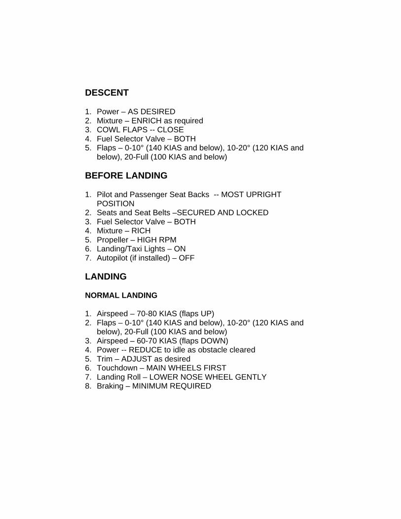
DESCENT
1. Power – AS DESIRED2. Mixture – ENRICH as required3. COWL FLAPS -- CLOSE4. Fuel Selector Valve – BOTH5. Flaps – 0-10° (140 KIAS and below), 10-20° (120 KIAS and
below), 20-Full (100 KIAS and below)
BEFORE LANDING
1. Pilot and Passenger Seat Backs -- MOST UPRIGHTPOSITION
2. Seats and Seat Belts –SECURED AND LOCKED3. Fuel Selector Valve – BOTH4. Mixture – RICH5. Propeller – HIGH RPM6. Landing/Taxi Lights – ON7. Autopilot (if installed) – OFF
LANDING
NORMAL LANDING
1. Airspeed – 70-80 KIAS (flaps UP)2. Flaps – 0-10° (140 KIAS and below), 10-20° (120 KIAS and
below), 20-Full (100 KIAS and below)3. Airspeed – 60-70 KIAS (flaps DOWN)4. Power -- REDUCE to idle as obstacle cleared5. Trim – ADJUST as desired6. Touchdown – MAIN WHEELS FIRST7. Landing Roll – LOWER NOSE WHEEL GENTLY8. Braking – MINIMUM REQUIRED
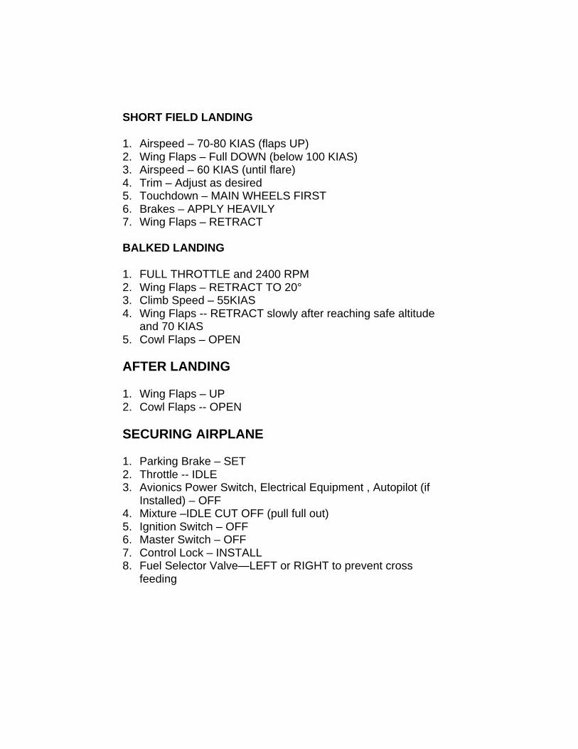
SHORT FIELD LANDING
1. Airspeed – 70-80 KIAS (flaps UP)2. Wing Flaps – Full DOWN (below 100 KIAS)3. Airspeed – 60 KIAS (until flare)4. Trim – Adjust as desired5. Touchdown – MAIN WHEELS FIRST6. Brakes – APPLY HEAVILY7. Wing Flaps – RETRACT
BALKED LANDING
1. FULL THROTTLE and 2400 RPM2. Wing Flaps – RETRACT TO 20°3. Climb Speed – 55KIAS4. Wing Flaps -- RETRACT slowly after reaching safe altitude
and 70 KIAS5. Cowl Flaps – OPEN
AFTER LANDING
1. Wing Flaps – UP2. Cowl Flaps -- OPEN
SECURING AIRPLANE
1. Parking Brake – SET2. Throttle -- IDLE3. Avionics Power Switch, Electrical Equipment , Autopilot (if
Installed) – OFF4. Mixture –IDLE CUT OFF (pull full out)5. Ignition Switch – OFF6. Master Switch – OFF7. Control Lock – INSTALL8. Fuel Selector Valve—LEFT or RIGHT to prevent cross
feeding
AIRSPEEDS
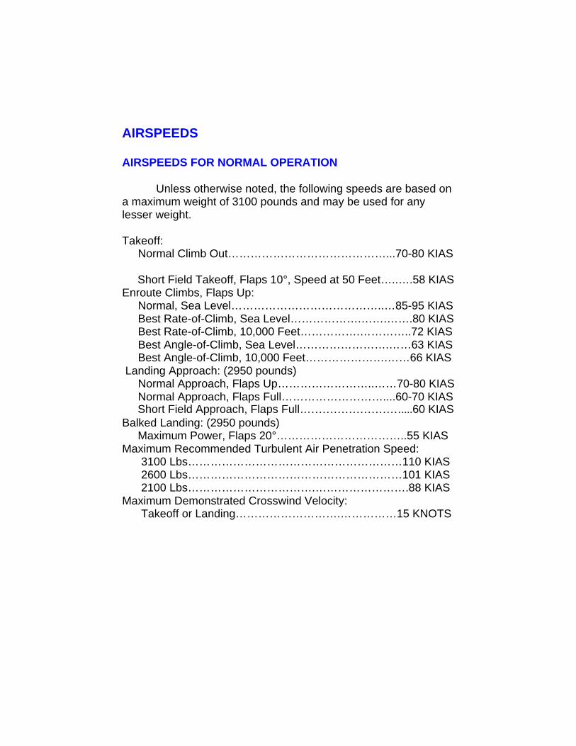
AIRSPEEDS FOR NORMAL OPERATION
Unless otherwise noted, the following speeds are based ona maximum weight of 3100 pounds and may be used for anylesser weight.
Takeoff: Normal Climb Out……………………………………...70-80 KIAS
Short Field Takeoff, Flaps 10°, Speed at 50 Feet…..….58 KIASEnroute Climbs, Flaps Up: Normal, Sea Level…………………………………..…85-95 KIAS Best Rate-of-Climb, Sea Level……………….…….…….80 KIAS Best Rate-of-Climb, 10,000 Feet…………….…………..72 KIAS
Best Angle-of-Climb, Sea Level…………………….……63 KIAS Best Angle-of-Climb, 10,000 Feet………………….……66 KIAS
Landing Approach: (2950 pounds) Normal Approach, Flaps Up……………………..……70-80 KIAS Normal Approach, Flaps Full………………………....60-70 KIAS Short Field Approach, Flaps Full………………………....60 KIASBalked Landing: (2950 pounds) Maximum Power, Flaps 20°……………………………..55 KIASMaximum Recommended Turbulent Air Penetration Speed: 3100 Lbs…………………………………………………110 KIAS 2600 Lbs…………………………………………………101 KIAS 2100 Lbs…………………………….…………………….88 KIASMaximum Demonstrated Crosswind Velocity: Takeoff or Landing……………………….……………15 KNOTS
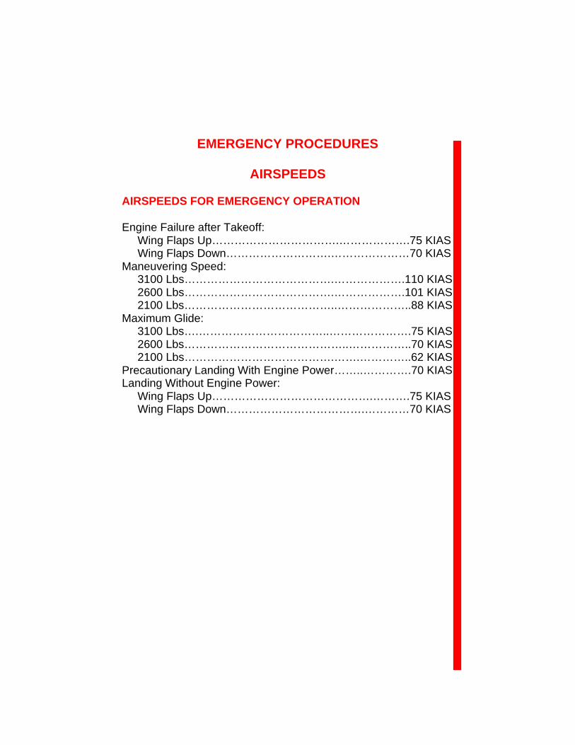
EMERGENCY PROCEDURES
AIRSPEEDS
AIRSPEEDS FOR EMERGENCY OPERATION
Engine Failure after Takeoff: Wing Flaps Up…………………………….……………….75 KIAS Wing Flaps Down……………………….…………………70 KIASManeuvering Speed: 3100 Lbs………………………………….……………….110 KIAS 2600 Lbs………………………………….……………….101 KIAS 2100 Lbs…………………………………..………………..88 KIASMaximum Glide: 3100 Lbs….……………………………..………………….75 KIAS 2600 Lbs……………………………………..……………..70 KIAS 2100 Lbs………………………………….…….…………..62 KIASPrecautionary Landing With Engine Power……..………….70 KIASLanding Without Engine Power: Wing Flaps Up…………………………………….……….75 KIAS Wing Flaps Down……………………………….…………70 KIAS
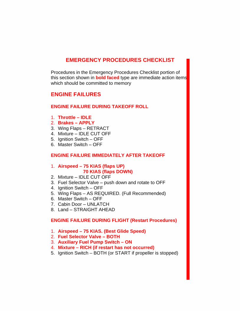
EMERGENCY PROCEDURES CHECKLIST
Procedures in the Emergency Procedures Checklist portion ofthis section shown in bold faced type are immediate action itemswhich should be committed to memory
ENGINE FAILURES
ENGINE FAILURE DURING TAKEOFF ROLL
1. Throttle – IDLE2. Brakes – APPLY3. Wing Flaps – RETRACT4. Mixture – IDLE CUT OFF5. Ignition Switch – OFF6. Master Switch – OFF
ENGINE FAILURE IMMEDIATELY AFTER TAKEOFF
1. Airspeed – 75 KIAS (flaps UP) 70 KIAS (flaps DOWN)
2. Mixture – IDLE CUT OFF3. Fuel Selector Valve – push down and rotate to OFF4. Ignition Switch – OFF5. Wing Flaps – AS REQUIRED. (Full Recommended)6. Master Switch – OFF7. Cabin Door – UNLATCH8. Land – STRAIGHT AHEAD
ENGINE FAILURE DURING FLIGHT (Restart Procedures)
1. Airspeed – 75 KIAS. (Best Glide Speed)2. Fuel Selector Valve – BOTH3. Auxiliary Fuel Pump Switch – ON4. Mixture – RICH (if restart has not occurred)5. Ignition Switch – BOTH (or START if propeller is stopped)
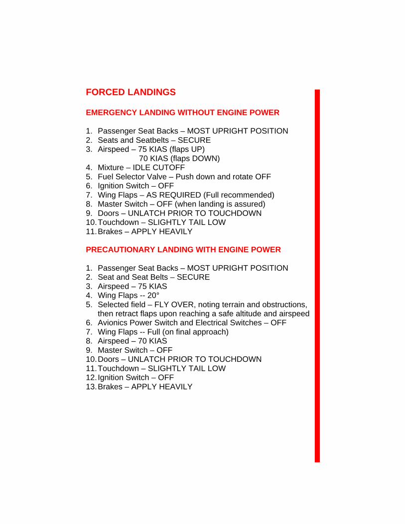
FORCED LANDINGS
EMERGENCY LANDING WITHOUT ENGINE POWER
1. Passenger Seat Backs – MOST UPRIGHT POSITION2. Seats and Seatbelts – SECURE3. Airspeed – 75 KIAS (flaps UP) 70 KIAS (flaps DOWN)4. Mixture – IDLE CUTOFF5. Fuel Selector Valve – Push down and rotate OFF6. Ignition Switch – OFF7. Wing Flaps – AS REQUIRED (Full recommended)8. Master Switch – OFF (when landing is assured)9. Doors – UNLATCH PRIOR TO TOUCHDOWN10. Touchdown – SLIGHTLY TAIL LOW11. Brakes – APPLY HEAVILY
PRECAUTIONARY LANDING WITH ENGINE POWER
1. Passenger Seat Backs – MOST UPRIGHT POSITION2. Seat and Seat Belts – SECURE3. Airspeed – 75 KIAS4. Wing Flaps -- 20°5. Selected field – FLY OVER, noting terrain and obstructions,
then retract flaps upon reaching a safe altitude and airspeed6. Avionics Power Switch and Electrical Switches – OFF7. Wing Flaps -- Full (on final approach)8. Airspeed – 70 KIAS9. Master Switch – OFF10. Doors – UNLATCH PRIOR TO TOUCHDOWN11. Touchdown – SLIGHTLY TAIL LOW12. Ignition Switch – OFF13. Brakes – APPLY HEAVILY
DITCHING
1. Radio – TRANSMIT MAYDAY on 121.5 MHz, giving locationand intentions and SQUAWK 7700
2. Heavy Objects (in baggage area) – SECURE OR JETTISON(if possible)
3. Passenger Seat Backs – MOST UPRIGHT POSITION4. Seats and Seat Belts – SECURE5. Wing Flaps -- 20° to 30°6. Power – ESTABLISH 300 FT/MIN DESCENT AT 65 KIAS
NOTE
If no power is available, approach at 70 KIAS with flaps upor at 65 KIAS with 10° flaps
7. Approach – High Winds, Heavy Seas – INTO THE WIND Light winds, Heavy Swells – PARALLEL TO SWELLS
8. Cabin Doors – UNLATCH9. Touchdown – LEVEL ATTITUDE AT ESTABLISHED RATE OF
DESCENT10. Face – CUSHION at touchdown with folded coat11. ELT – Activate12. Airplane – EVACUATE through cabin doors. If necessary,
open window and flood cabin to equalize pressure so doors can be opened
13. Life Vests and Raft – INFLATE WHEN CLEAR OF AIRPLANE
FIRES
DURING START ON GROUND
1. Cranking – CONTINUE to get a start which would suck theflames and accumulated fuel into the engine
If engine starts:
2. Power – 1700 RPM for a few minutes3. Engine – SHUTDOWN and inspect for damage
If engine fails to start:
4. Throttle – FULL OPEN5. Mixture – IDLE CUT OFF6. Cranking – CONTINUE7. Fuel Selector Valve – Push down and rotate to OFF8. Auxiliary Fuel Pump – OFF9. Fire Extinguisher – OBTAIN (have ground attendants obtain if
not installed)10. Engine – SECURE
a. Master Switch – OFFb. Ignition Switch – OFF
11. Parking Brake – RELEASE12. Airplane – EVACUATE13. Fire – EXTINGUISH using fire extinguisher, wool blanket, or
dirt14. Fire Damage – INSPECT repair damage or replace damaged
components or wiring before conducting another flight
ENGINE FIRE IN FLIGHT
1. Mixture – IDLE CUT OFF2. Fuel Selector Valve – Push down and rotate to OFF3. Auxiliary Fuel Pump Switch – OFF4. Master Switch – OFF5. Cabin Heat and Air – OFF (except overhead vents)6. Airspeed – 100 KIAS (if fire is not extinguished, increase glide
speed to find an airspeed – within airspeed limitations – whichwill provide an incombustible mixture)
7. Forced Landing – EXECUTE (as described in EmergencyLanding without Engine Power)
ELECTRICAL FIRE IN FLIGHT
1. Master Switch – OFF2. Vents, Cabin Air, Heat – CLOSED3. Fire Extinguisher – AVTIVATE (if available)4. Avionics Power Switch – OFF5. All Other Switches (except ignition switch) – OFF
ssWARNING
AFTER DISCHARGING FIRE EXTINGUISHER ANDASCERTAINING THAT FIRE HAS BEEN
EXTINGUISHED, VENTILATE THE CABIN
6. Vents/Cabin Air/Heat – OPEN when it is ascertained that fire iscompletely extinguished
If fire has been extinguished and electrical power is necessary forcontinuance of flight to nearest suitable airport or landing area
7. Master Switch –ON8. Circuit Breakers – CHECK for faulty circuit, do not reset9. Radio Switches – OFF10. Avionics Power Switch – ON11. Radio/Electrical Switches – ON one at a time, with delay after
each until short circuit is localized
CABIN FIRE
1. Master Switch – OFF2. Vents/Cabin Air/Heat – CLOSED (to avoid drafts)3. Fire Extinguisher – ACTIVATE (IF AVAILABLE)
ssWARNING
AFTER DISCHARGING FIRE EXTINGUISHER ANDASCERTAINING THAT FIRE HAS BEEN EXTINGUISHED ,
VENTILATE THE CABIN
4. Vents/Cabin Air/Heat – OPEN when it is ascertained that fire is completely extinguished5. Land the airplane as soon as possible to inspect for damage
WING FIRE
1. Landing/Taxi Light Switches – OFF2. Navigation Light Switch – OFF3. Strobe Light Switch – OFF4. Pitot Heat Switch – OFF
STATIC SOURCE BLOCKAGE(Erroneous Instrument Reading Suspected)
1. Static Pressure Alternate Source Valve -- PULL ON2. Airspeed – Consult appropriate calibration tables in Section 5
LANDING WITH A FLAT MAIN TIRE
1. Approach – NORMAL2. Wing Flaps – Full3. Touchdown – GOOD MAIN TIRE FIRST, hold airplane off flat
tire as long as possible. With aileron control4. Directional Control – Maintain using brake on good wheel as
required
LANDING WITH A FLAT NOSE TIRE
1. Approach – NORMA2. Flaps – AS REQUIRED3. Touchdown – ON MAINS, hold nose wheel off the ground as
long as possible4. When nose wheel touches down, maintain full up elevator as
airplane slows to stop

ELECTRICAL POWER SUPPLY SYSTEMMALFUNCTIONS
AMMETER SHOWS EXCESSIVE RATE OF CHARGE(Full Scale Deflection)
1. Alternator – OFF2. Nonessential Electrical Equipment – OFF3. Flight – TERMINATE as soon as practical
LOW VOLTAGE ANNUNCIATOR (VOLTS) ILLUMINATESDURING FLIGHT(Ammeter Indicates Discharge)
NOTE
Illumination of “VOLTS” on the annunciator panel mayoccur during low RPM conditions with an electrical load onthe system such as during low RPM taxi. Under theseconditions, the light will go out a t higher RPM. The masterswitch need not be recycled since an overvoltage conditionhas not occurred to deactivate the alternator system
1. Avionics Power Switch – OFF2. Alternator Circuit Breaker – CHECK IN3. Master Switch – OFF (both sides)4. Master Switch – ON5. Low Voltage Annunciator – CHECK OFF6. Avionics Power Switch – ON
If low voltage illuminates again:
7. Alternator – OFF8. Nonessential Radio and Electrical Equipment – OFF9. Flight – TERMINATE as soon as practical
VACUUM SYSTEM FAILURE(Left Vacuum or Right Vacuum Annunciator Light (LVAC R) Illuminates).
ssCAUTION
IF VACUUM IS NOT WITHIN NORMALOPERATING LIMITS, A FAILURE HASOCCURRED IN THE VACUUM SYSTEM ANDPARTIAL PANEL PRECOEDURES MAY BEREQUIRED FOR CONTINUED FLIGHT
1. Suction Gage – CHECK to ensure vacuum within normaloperating limits