
Baltelle - NASA
35
RESEARCH REIPORI 0 Baltelle Columbus I abo)ratories J I e 2 .. ~I,, j7 1 14EP'SU. 'NG ~N72L~-157 ott - 12 1 216 0 O) CON ACT10 1 E4 SUIG ITE1TO4L OTIACATE DpRTS Quarterly Repo-rt D/ , . AL Ro~uT'-N PAR 1 (Battelle KeMOIa' CSCL 1LB G B 1 D.Bo H1a97il-oe" 33 P C / ~ ~ ~ ~ ~ ~ ~ ~ ~ N TO A .uCoICA Reproaucea by NATIONAL TECHNICAL INFORMATION SERVICE U S Department of Commerce Springfield VA 22151 :--- ~ ~ -- . -- - - - - .* I 4, .
Transcript of Baltelle - NASA
RESEARCH REIPORI
0 BaltelleColumbus I abo)ratories J I e 2
.. ~I,, j71
14EP'SU. 'NG
~N72L~-157 ott -12 1 216 0 O) CON ACT10 1 E4 SUIG
ITE1TO4L OTIACATE DpRTS Quarterly Repo-rtD/ , . AL Ro~uT'-N PAR 1 (Battelle KeMOIa'
CSCL 1LB G B1 D.Bo H1a97il-oe" 33 P C
/ ~ ~ ~ ~ ~ ~ ~ ~ ~ N TO A .uCoICA
Reproaucea by
NATIONAL TECHNICALINFORMATION SERVICE
U S Department of CommerceSpringfield VA 22151
:--- ~ ~ -- . -- - - - -
.* I
4, .

* : . . ; > u ' : 5!t
i~~~~~~~~~~i~~~~
,~~~~~~~i ...
!i~~~~~~~~:
X , . . i fs i. .
; :~ ~~~~ t ;i' fli·' l ' t'
V ^,, 1' '3 i.i a ' i '~' ij'.i ':
'
~ .
: ' ; ' I
.:,,.S i,
' !' i; !I~
-a _ i .. .
: .:.'
I ; r } z1
. 'M' '
V , * ':, '< l t .n, t , -;,; x 0fl.-'i jg i I 0
'BATTEL'.s CQLCUMBUS' LABOIRkATs)I ..comprises the' origi-nal research cntenr d!aii international" oitanization devoted to researchand development.
Battelle is frequently described as a "bridge" between science andindustry -'a role it has performed in, rnre than 90 countries. Itconducts research encompassing virtuallyalt. fets of science and itsapplication. It also undertakes :prograims. rj, fundamental research andeducation.
Battelle-Columbus - with its staff of 2500 - serves industry andgovernment through contrattesearch. It purses.:
* research- embracing the physical a n life sciences, engi-neerinfg, and selected social scienjce . ' i '
·*design and development of materials, products, processes,:and systems '
* information analysis, socioeconomic and technical eco-nomic studies, and management planning research.
0·
505 KING AVENUE * COLUMBUS, OHIO 43201
: I ,
i';
:n :E r~, .. 0:
0: D 1..:.' ' £ , ,
I
SECOND QUARTERLY REPORT
on
NONCONTACTING MEASURING DEVICE TO INDICATEDEFLECTION OF TURBOPUMP INTERNAL ROTATING PARTS
to
NATIONAL AERONAUTICS AND SPACE ADMINISTRATIONGEORGE C. MARSHALL SPACE FLIGHT CENTER
by
D. B. Hamilton, D. R. Grieser, A. M. Plummer,Dale Ensminger, E. J. Saccocio, and J. W. Kissel
September 20, 1971
Period Covered: June 1 to August 31, 1971
BATTELLEColumbus Laboratories
505 King AvenueColumbus, Ohio 43201
0o
TABLE OF CONTENTS
SUMMARY . . . . . . . . . . . . . . . . . . . . . . . . . . . . . . . .
INTRODUCTION . . . . . . . . . . . . . . . . . . . . . . . . . . . . .
ULTRASONIC TECHNIQUES .........................
Methods of Measuring Thickness . . . . . . . . . . . . . . .
Methods Based on Pulse Travel Time . . . . . . . . . . .
Methods Based on Resonance Frequencies of Standing WavesBetween Two Reflecting Surfaces . . . . . . . . . . .
Basis for Rejection . . . . . . . . . . . . . . . . . .
Methods of Measuring Vibration Amplitudes . . . . . . . . . .
Methods Based on Beam Interference or Deflection
Methods Based Upon Doppler Shifts.
Basis for Recommendation
RADIOISOTOPE AND GAMMA-RAY DEVICES . . .
X-RADIOGRAPHY . . . . . . . . . . . . . .
OPTICAL TECHNIQUES . . . . . . . . . . .
NEUTRON RADIOGRAPHY . . . . . . . . . . .
Turbopump Model . . . . . . . .
Real-Time Imaging . . . . . . .
Thermal Neutron Radiography
Fast Neutron Imaging . . . . .
CONVENTIONAL DISPLACEMENT SENSORS . . . .
Magnetic and Capacitance Techniques.
Nonslip-Ring Signal Transmission . .
DISCUSSION . . . . . . . . . . . . . . . .
Page
1
2
3
4
4
5
5
5
. . . 5
6
. . . . . . . . . . . .. . . 6
. . . . . . . . . . . . . . . 7
. . . . . . . . . . . . . . . 7
·. . . . . . . . . . . . . . .· · · · · · 9
. . . . . . . . . . . . . . . 12
. . . . . . . . . . . . . . . 14
. . . . . . . . . . . . . . . 16
. . . . . . . . . . . . . . . 17
. . . . . . . . . . . . . . . ....19
. . . . . . . . . . . . . . . 23
. . . . . . . . . . . . . . . 23
. . . . . . . . . . . . . . . 25
26
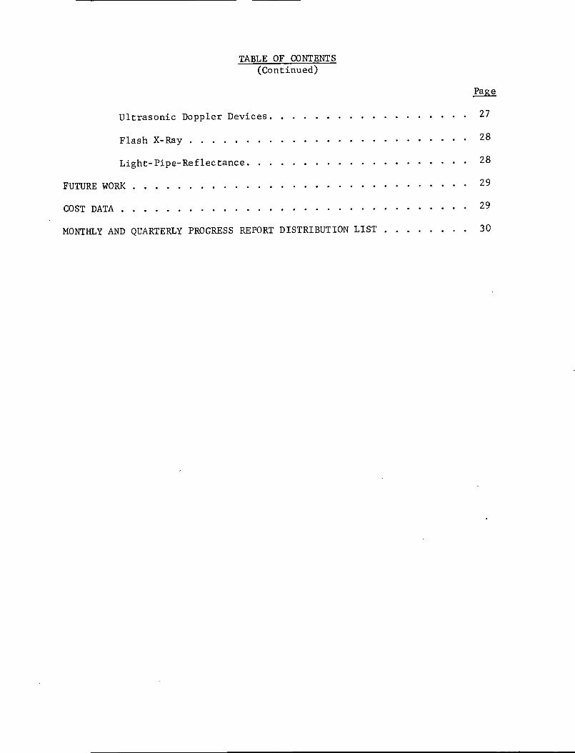
TABLE OF CONTENTS(Continued)
Page
Ultrasonic Doppler Devices. . . . . . . . . . . . . . . . . . 27
Flash X-Ray ......................... 28
Light-Pipe-Reflectance. . . . . . . . . . . . . . . ..... 28
FUTURE WORK . . . . . . . . . . . . . . . . . .. .. . . . . . . . . . 29
COST DATA ............................... 29
MONTHLY AND QUARTERLY PROGRESS REPORT DISTRIBUTION LIST . . . . . ... 30
NONCONTACTING MEASURING DEVICE TO INDICATEDEFLECTION OF TURBOPUMP INTERNAL ROTATING PARTS
(Contract NAS8-26903)
by
D. B. Hamilton, D. R. Grieser, A. M. Plummer,Dale Ensminger, E. J. Saccocio, and J. W. Kissel
SUMMARY
This is the second quarterly report on the program to develop
noncontacting,nondestructive techniques to measure vibrations and deflections
of parts in future LOX and LH2multistage turbopump prototypes. The measure-
ments of interest include shaft vibration, vibration of turbine wheel and
blades, blade clearance, vibration of impellers, valve component flutter, and
vibration of face seal components. This report summarizes the results of
Phase I (Feasibility Study).
With the exception of a new idea for a fast-neutron detection
technique, evaluation of the various techniques was concluded. As a result
of a meeting between MSFC and BCL (Battelle's Columbus Laboratories) personnel,
three techniques were selected for Phase II (Development). These are
(1) Ultrasonic Doppler devices
(2) Flash X-ray
(3) Light-pipe reflectance.
An old J-2 turbopump will, if possible, be made available to assist the develop-
ment of the three techniques. The results of the evaluations conducted during
the second quarter are as follows.
Examination of drawings of several turbopumps has indicated that the
ultrasonic Doppler approach is feasible for the pump sections where a solid
acoustical path is available from pump case to the part being measured. It
is likely that solid paths cannot be found in the turbine section; so this
approach may be unsuccessful for measuring vibrations of turbine blades or
wheels. Ultrasonic Doppler devices are not expected to require substantial
pump modification.
2
Our studies have indicated that neutron radiography cannot provide
real time measurements. Thermal neutron sources are too large to provide
sufficient resolution for the turbopump application. Fast-neutron radiography
would suffer from excessive scattering, reducing contrast. A new fast-neutron
detection device has been conceived which may allow displacement measurements
to be made at a single point. It is recommended that Phase I be continued
to evaluate feasibility of the idea.
Experiments with a flash X-ray unit have demonstrated that neither
motion nor a 1-inch-thick piece of interposed aluminum appear to reduce
resolution significantly. Further, repetitive pulsing of the unit does not
deteriorate the resolution of the radiograph produced. Our evaluations
indicate that flash X-rays are feasible for the application. The ability to
penetrate very thick sections is questionable. Flash X-rays may be appropriate
only for the turbine sections; however, this judgement can only be made after
experimentation with an actual turbopump.
A light-pipe-reflectance device was purchased and evaluated. If
the required turbopump modification is possible, this technique appears feasible
for the pump sections and the turbine wheel. The high temperature of the
turbine blades may preclude its use in that area, although turbine wheel
measurements appear feasible.
The evaluation of Mbssbauer analysis of gamma rays was concluded.
The use of frequency modulation of a carrier wave by Doppler-shifted gamma
rays was judged not feasible. The magnitude of vibrational displacement
encountered in turbopumps is sufficient to spread the vibrational information
over numerous FM side bands.
Evaluation of inductance, eddy-current, and capacitance techniques
failed to produce an approach which appeared substantially better than the
Bentley inductance probes currently in use. Signal transmitters appear to be
a feasible way to replace contact-type slip rings.
INTRODUCTION
The purpose of this program is to develop noncontacting, nondestructive
devices to measure vibrations and deflections of internal parts in future LOX
and LH2 multistate turbopump prototypes. The program is a three-phase effort
3
in which Phase I is a feasibility study resulting in approximately three
candidate approaches, Phase II is a development study, and Phase III involves
experimental verification.
This second quarterly report summarizes the results of Phase I
(Feasibility Study). As a result of a meeting held at MSFC on August 24, 1971,
between BCL and MSFC project personnel, three approaches were selected for
development in Phase II. Shortly after the meeting, a new idea was conceived
to permit application of fast neutrons to the application. Since the idea
appears worthwhile, BCL has recommended that Phase I be continued for another
quarter (concurrent with Phase II) to evaluate the feasibility of the new idea.
During the meeting held at MSFC, it was agreed that an old J-2
turbopump in running condition would be made available to BCL to assist us in
our development of the three approaches. After receiving the pump, we plan to -
mount it in such a way that it can be driven at partial speed by an external
drive. This will enable us to evaluate and develop each technique with respect
to realistic conditions.
During the first quarter of the program, literature searches were
conducted and interviews held with manufacturers representatives to uncover
potential measurement techniques. Evaluations were begun of techniques which
appeared applicable. Both paper studies and experiments were conducted. During
the second quarter, the experimental and theoretical feasibility evaluations
were concluded (with the exception of a fast-neutron technique) and three
approaches were recommended for advancement into Phase II.
Progress in each technical category is summarized briefly below,
followed by a brief discussion of the relative merits of each of the three
recommended approaches.
ULTRASONIC TECHNIQUES
Ultrasonic waves are capable of penetrating most engineering materials
to considerable depths and they do this at low energy levels. In addition,
they are capable of being guided through curved paths. They are sensitive to
abrupt changes in acoustic impedance and for this reason they have been used
to measure thickness of materials, to measure distances to target areas, and
to locate defects in materials.
4
Methods of generating, detecting, and processing ultrasonic data
are numerous. Several of these have been evaluated as possible means of
measuring the deflection of turbopump internal rotating parts such as shafts.
During the first quarter, we concluded that ultrasonic Doppler devices
appeared feasible, but were dependent on the actual geometry of the turbopump
involved. During the second quarter, examination of drawings representative
of a variety of turbopump designs have convinced us that ultrasonic Doppler
techniques are definitely applicable to turbopumps; however, not all of the
desired measurements are likely to be possible. In general, since a solid
path is required from ultrasonic source to the part measured, measurements in
the turbine sections will be difficult, if not impossible. In particular,
measurements of turbine blade vibration or clearance, turbine wheel vibration,
or turbine shaft movement may not be feasible. On the other hand, impeller or
diffuser vibration or other movement in the pump sections would definitely
appear to be feasible. The attractive feature of ultrasonic Doppler measurements,
of course, is that if the source and receiver are ridgidly fixed to the pump
case, very little modification of the pump is needed.
A summary of the techniques evaluated is given below.
Methods of Measuring Thickness
Two basic principles are used conventionally to measure thicknesses.
These are (1) time of travel of a pulse of energy between two reflecting
surfaces, and (2) resonance frequencies of standing waves between two reflecting
surfaces.
Methods Based on Pulse Travel Time. These methods are useful for
measuring thicknesses or distances between static reflecting surfaces at any
depth which does not exceed the penetrable depth of the ultrasonic energy.
Electronic gating can be employed to restrict measurements to a specified
distance.
Dynamic measurements can be made by recording the travel times
between the two reflecting surfaces and the difference between them.
Basis for Rejection. There is much in favor of pulse travel time
methods for measuring displacements in the turbopump system. In fact, the
method recommended incorporates some of the favorable aspects of the pulse
�
5
methods. Three weaknesses of the pulse travel time methods that the recommended
method is expected to correct are (1) need for extremely short pulse within
the measurement region, (2) sensitivity to spurious echoes occurring between
the echoes from the two reflecting surfaces, and (3) poor accuracies of present
methods in measuring very small displacements.
Methods Based on Resonance Frequencies of Standing Waves Between Two
Reflecting Surfaces. Two methods of measuring thicknesses by resonance are in
common use. Both require frequency modulation. The methods used are (1)
continuous wave and (2) pulse interference. The continuous wave resonance
method is used to measure thicknesses of materials, such as plates, in which
one surface is in direct contact with the ultrasonic probe or is separated
from it by-a liquid path. The pulse interference method of measurement of
thicknesses is based upon the differences in transmission through a material
at resonance and at antiresonance. The pulse may be monochromatic with the
frequency swept through a range or it may be broadband and the received pulse
subjected to frequency analysis.
Basis for Rejection. These methods cannot be applied easily to the
turbopump displacement measurement. The continuous wave measurement requires
parallel surfaces of fairly large areas and high frequencies of operation.
Distances to the vibrating surfaces are excessive compared with the amplitudes
of vibration to be detected.
Methods of Measuring Vibration Amplitudes
Methods Based on Beam Interference or Deflection. Beam-interference
refers to the interference of the propagation of a beam of ultrasonic energy
by an obstacle. If a beam of energy is directed between two members which are
vibrating relative to each other, the total energy transmitted through the gap
is modulated by the relative motion. By sensing the total energy change, it
is possible to determine the relative displacement between the vibrating surfaces.
Beam deflection can be used to measure displacements of vibrating
bodies by shifts in positions of reflected beams.
Basis for Rejection. Beam interference and beam deflection methods
cannot be used in the turbopump to measure deflections. The problem is one
of appropriately locating the transducers in the turbopump to obtain the
desired beam directions.
6
Methods Based Upon Doppler Shifts. Doppler shifts are changes in
frequency observed by a receiver due to changing the distance traveled by waves
between a transmitter of the waves and the receiver. A moving target can
produce the changes in frequency even with the transmitter and receiver fixed
in position. The change in frequency depends upon the velocity of the target
and the direction of its motion.
The Doppler method is recommended for use in measuring the displace-
ments in the rotating parts of the turbopump.
Basis for Recommendation. The Doppler method can be designed to
combine the desirable characteristics of pulse methods. For instance, it
can be pulsed (using pulse-sampling techniques) and gated, thus eliminating
effects from vibrating surfaces that are more remote than those of interest.
The received signal can be filtered over a narrow band corresponding to the
maximum frequency shifts to be expected due to the target amplitudes of
vibration. This filtering eliminates most vibrational noises. A further
noise reduction occurs by filtering after the Doppler signal has been extracted.
Pulses for Doppler measurements can be guided to an area of interest
through wave guides which may be a normal part of the structure being monitored
or, if necessary, additional members conveniently located. The path should not
be too complicated. Complicated paths may result in spurious indications.
The major problem with ultrasonic techniques is that of transferring
energy from one medium to the next. Transfer from liquid to solid in the
absence of cavitation can be accomplished effectively. Transfer from gas to
solid or vice versa requires special treatment. The measurements in the turbo-
pump will be restricted to solid and liquid paths.
Published values of the ultrasonic characteristics of cryogenic
materials are favorable to the ultrasonic approach to the measurement of the
vibration of the rotating parts in the turbopump.
The detector used for measuring displacements by the ultrasonic
Doppler method also can be used to detect anomalous sounds (sonic analysis).
Sonic analysis is often an inexpensive method of detecting incipient failures
of machine parts before they become catastrophic.
7
RADIOISOTOPE AND GAMMA-RAY DEVICES
Our evaluations have been concerned with M6ssbauer analysis of gamma
rays from a source attached to the moving part to be measured. Previously,
we showed that a simple M-ossbauer detection scheme was not feasible for the
relatively large vibrational velocities associated with vibrating turbopump
components. During the second quarter we evaluated the possibility of moving
the absorber to sense the gamma radiation from the source.
There would appear to be at least two possible detection schemes
associated with moving the absorber. The first would involve synchronizing
the absorber with the source vibration. The fact that the source may vibrate
at several frequencies characteristic of critical frequencies of, say, the
turbine wheel, would appear to make the synchronizing system prohibitively
complex. The second possibility involves vibrating the absorber at a high
frequency and allowing the Doppler-shifted signal from the source to, in effect,
frequency-modulate it. Our calculations show, however, that the range of
Doppler velocities to be anticipated will result in numerous side bands,
spreading the vibration information over such a wide range of frequencies
that the inference of vibration magnitudes and frequencies may be impossible.
Simply stated, Mbossbauer analysis is a much too sensitive measuring technique
for something as large as a turbopump.
No other detection scheme was conceived which offered a good
possibility of using radioisotopes or gamma rays.
X-RADIOGRAPHY
During the first quarter, evaluation of pulsed, or flash, X-radiography
was begun. Commercial flash X-ray apparatuses can be pulsed a few milliseconds
apart with a pulse duration of about 20 nanoseconds. These parameters are
consistent with 35,000 rpm pump operation. During the second quarter, a series
of experiments designed to assess penetration and resolution was completed.
The results of the experiments indicate that resolution is expected to be
sufficient to detect movement of perhaps 0.02 mm or less. Penetration, however,
is questionable. It is likely that turbine blade movement or clearance can be
8
measured, since very little metal mass surrounds the turbine section. It
may not be possible to sense vibrations in the pump section, because of the
relatively thick pump case surrounding that section.
The experiments performed involved the use of a 3.8-cm diameter mild
steel shaft with abrupt reductions in radius of 0.12 mm (5 mils), 0.25 mm
(10 mils), and 0.5 mm (20 mils). First a flash X-ray was taken with the
source and film about four centimeters from the shaft. Resolution was excellent;
the 0.12 mm step was readily apparent on the film negative.
Next, a 2.5-cm-thick aluminum plate was interposed between the source
and shaft to simulate scattering by the pump case. Resolution was not reduced
significantly.
The final experiment with the stepped shaft involved evaluation of
focal point migration with pulse repetition. The shaft (with interposed
aluminum plate) was exposed twice at half intensity. No difference was
observable with the negative from the previous experiment. The result of
this experiment shows that focal point migration in the X-ray tube is
insufficient to cause a significant loss of resolution. In addition, it
suggests that repetitive pulsing may be a means to increase intensity. Flash
X-ray units are available with up to ten heads for repetitive pulsing.
An additional experiment with a small (15-cm-diameter) electric
motor was performed. Radiographs were taken with the motor stationary and
running at 1200 rpm. It is not possible to distinguish between the two
radiographs without identification. Good definition of wires and components
within the motor is apparent. Definition of bearings and components behind
thick metal sections is not good, however, suggesting that penetration may be
inadequate for the pump section of turbopumps.
The fact that a 0.12-mm step can be detected by the naked eye in
the shaft experiments indicates that much smaller variations could be detected
by photographic processing and densitometry. The fact that excessive scattering
was not observed in the motor photographs suggests that flash X-rays are
appropriate for complicated structures. The big question, however, is whether
flash X-rays will penetrate sufficiently to be used for components (such as
impellers) which are inside relatively thick sections of metal. This question
9
can only be resolved by attempting radiographs of actual turbopumps. There
is no question that flash X-rays are appropriate for components such as
turbine blades where the thickness of metal separating them from the film
would not be great.
OPTICAL TECHNIQUES
During the first quarter, a large number of optical techniques were
evaluated. We concluded that the most promising was a commercially available
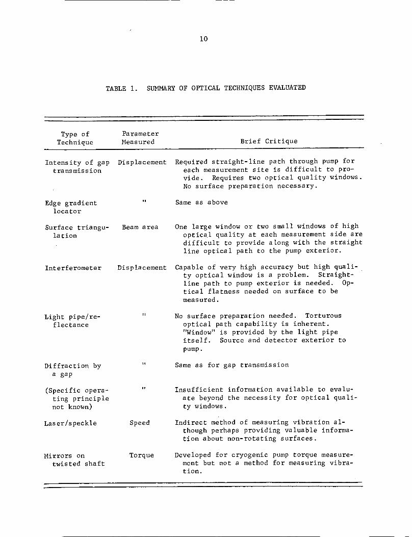
light-pipe-reflectance system. Table 1 summarizes our evaluation of various
optical techniques. We purchased a light-pipe-reflectance unit ("Fotonic")
and conducted a series of experimental evaluations.
Evaluations of the performance of the Fotonic sensor under ordinary
laboratory conditions have confirmed the manufacturer's claims. A high-speed
grinding attachment was mounted on the crossfeed of a small lathe. A small
rotor was chucked in the grinder collet. Each fiber-optic-sensor probe was
mounted, in turn, into the stationary lathe chuck. The average separation
between the probe end and the rotor was adjusted by using the fool-feed
micrometer drive. A solid state voltage control was used to select rotor
speeds up to 4500 rpm. Six small flats located around the rotor periphery
served to yield distinct displacement pulses at rates up to 27,000 pulses per
minute. Surface roughness contributed less distinct and less uniform pulses
at rates roughly 10 times higher (or the equivalent of 200,000 pulses per
minute). The manufacturer's data indicate a flat response for the instrument
out to 6 x 10⁶ pulses per minute with an attenuation of 5 percent at 107 pulses
per minute. The experiments showed that the instrument was quite stable and
it should be capable of a precision of several percent of the linear range,
as claimed.
A second experiment was performed in which the signal output from
the sensor was fed into a tunable frequency detector. As anticipated, a band
of frequencies was generated by surface imperfections whose center frequency
was linearly proportional to the rotor surface velocity. The band width at
half maximum was about 10 percent of the center frequency. It is estimated
10
TABLE 1. SUMMARY OF OPTICAL TECHNIQUES EVALUATED
Type of ParameterTechnique Measured Brief Critique
Intensity of gaptransmission
Displacement Required straight-line path through pump foreach measurement site is difficult to pro-vide. Requires two optical quality windows.No surface preparation necessary.
IIEdge gradientlocator
Same as above
Surface triangu-lation
Interferometer
Beam area
Displacement
One large window or two small windows of highoptical quality at each measurement side aredifficult to provide along with the straightline optical path to the pump exterior.
Capable of very high accuracy but high quali-ty optical window is a problem. Straight-line path to pump exterior is needed. Op-tical flatness needed on surface to bemeasured.
Light pipe/re-flectance
Diffraction bya gap
(Specific opera-ting principlenot known)
Laser/speckle
Mirrors ontwisted shaft
No surface preparation needed. Torturousoptical path capability is inherent."Window" is provided by the light pipeitself. Source and detector exterior topump.
I I
Speed
Torque
Same as for gap transmission
Insufficient information available to evalu-ate beyond the necessity for optical quali-ty windows.
Indirect method of measuring vibration al-though perhaps providing valuable informa-tion about non-rotating surfaces.
Developed for cryogenic pump torque measure-ment but not a method for measuring vibra-tion.
11
that one could determine dynamic changes in surface speed to within several
percent using an FM detection scheme. He-Ne laser illumination was used in
some of the experiments; however, there was no improvement in operation. The
sensor gain could be turned down considerably since the laser provided more
irradiance of the surface, but this technique is not sensitive to signal
amplitude. . .it is sensitive to frequency only. The laser might be of
more value in creating a more distinctive frequency spectrum in cases where
the surface is much smoother than was the test rotor used here.
Some consideration has been given to the problem of sealing the
sensor end where it will be subjected to hostile environments. The manufacturer
of the Fotonic sensor has used this type of sensor at liquid-nitrogen
temperatures. They have also operated others at pressures of 1500 psi. The
fibers in the standard probes are of the clad type, and this type is necessary
to keep down the optical cross talk. A quick experiment with a rigid fiber-
optical pipe containing unclad fibers showed that a second section of the
fiber pipe could be used as a "window". However, the experiment also showed
that the cross talk from the 5-cm length of unclad fibers lowered the
sensitivity by an order of magnitude. The use of clad fibers or of a much
shorter length of unclad fibers could result in nearly full regaining of
sensitivity., The interest in this involves the possibility of using a
rigid section of fiber bundles as a high pressure window and the normal
flexible section as a lead out. This has good promise for solving the problem
at cryogenic temperatures. The elevated temperatures in the turbine section
are a more difficult matter. We have been unable to locate clad fiber components
having promise of an usefulness above 1022 F, and there is no guarantee of
extended life above 842 F. Consequently, we hold out very little hope of
measuring using optical means in the vicinity of the 1700 F regions in the
turbine. On the other hand, we believe that there is reasonable promise
that small transparent gaps can be measured with high precision in the
cryogenic pump system using the fiber optic/reflectance approach. The major
impediment appears to be the possibility of cavitation in the measurement gap
which would render the signal meaningless insofar as displacement is concerned.
(The cavitation itself might be revealed by a strong output signal whose
central frequency corresponds to one-half the relative lateral velocity between
12
the probe and the surface being measured.) There are optical methods for
carrying signals to and from the shaft of the pump. Therefore, sensors might
be mounted in the rotating member if desired without the necessity for any
electrical or mechanical connection to the shaft.
NEUTRON RADIOGRAPHY
Neutron radiography makes use of neutrons instead of X-rays
usually used in radiographic techniques. Although neutron sources produce
fast neutrons, conventional neutron radiography uses thermal neutrons to
take advantage of the higher cross sections displayed by most materials for
thermal-neutron capture. Neutron radiography is inherently attractive for the
turbopump application, since neutrons can be expected to pass through relatively
thick sections of metal.
A feasibility study has been conducted on the basis of simple
calculation for a simple pump configuration. The results of this study
indicate the following.
(1) Real-time radiographic examination of an operating
turbopump is a practical impossibility. The time
segments available to form images of components
vibrating at the frequencies corresponding to
typical operating speeds would require a neutron
beam intensity that is not available with any
existing type of neutron source.
(2) Pulsed neutron sources--reactor and accelerator--can
provide time segments short enough to image components
vibrating at typical frequencies, but such sources
have other limitations that preclude their application
to this problem. A pulsed reactor source could
provide an intensity high enough to produce an image
within thetime of a single pulse, but the pulse rate is
very low (typically several pulses per hour) so only
extremely stable vibrations could be imaged. The
13
situation with accelerator sources is similar;
in this case, however, the source is intensity
limited and a large number of pulses would have
to be integrated to form an image, thus restricting
its application to extremely stable situations.
(3) The application of thermal neutron radiography
to this problem is limited by the geometrical
nature of the source itself. The finite size
and diffuse nature of the source, and the
imaging geometry imposed by the shape and size
of the turbopump produce a situation in which
the geometrical unsharpness is greater than the
features of interest. Our analysis indicates
that further investigation of thermal neutron
radiography is unwarranted.
(4) Several fast neutron sources (californium-252
in particular) provide beam geometries that
are equal to or better than those attainable
from X-ray sources, and thus have the best
potential for this application. From the
standpoint of the pump itself, attenuation
coefficients are high enough to produce
sufficient contrast for imaging. The con-
ventional means of fast neutron imaging are
much too insensitive to be used for this
application, but a recently conceived electronic
fast neutron imaging system appears to offer
sufficient sensitivity and resolution to meet
some of the requirements of this program. We
recommend that additional analytical and
experimental efforts be directed to the develop-
ment of this imaging system.
(5) Turbopump materials are an important factor, but
are secondary in importance to source and imaging
14
factors, particularly in the case of fast neutron
radiography. Although certain materials exhibit
unusually high attenuation coefficients for thermal
neutrons, the incorporation of these materials in
turbopump components for the purpose of enhancing
contrast does not appear to offer sufficient
improvement to offset the inherent disadvantages
of thermal neutron radiography in this application.
In consideration of the factors summarized above, the investigation indicates
that this application of neutron radiography is marginal with currently
available sources and imaging methods, but that the investigation should be
extended to include the evaluation and possible development of an advanced
concept in fast neutron imaging. Details of the analyses leading to this
conclusion are summarized below.
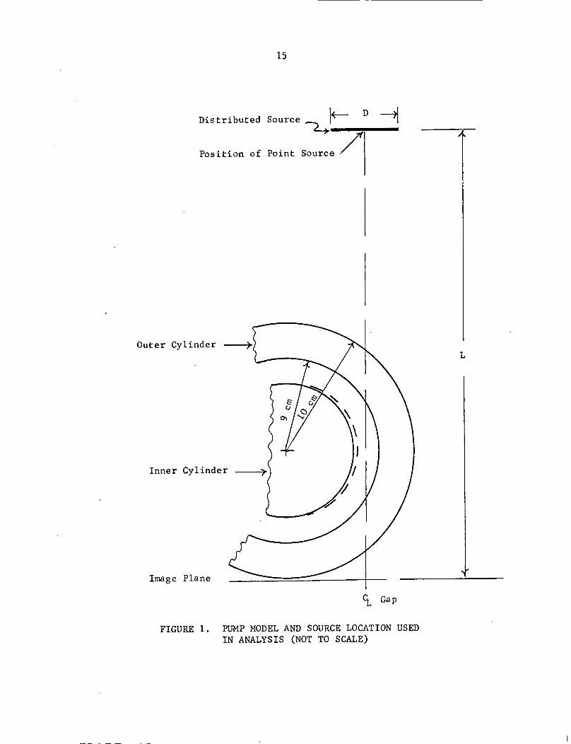
Turbopump Model
The turbopump model used in this analysis is shown in Figure 1; the
pump was assumed to consist of solid concentric cylinders. The analysis was
focused on the annulus between the two components, and in particular comprised
the calculation of neutron transmission through the region of the annulus with
(1) the cylinders concentric and (2) with the inner cylinder displaced. The
contrast difference between these two conditions is indicative of the
capability to detect radial vibration of the inner cylinder with respect to
the outer (or vice versa). Only two-dimensional aspects were included. In
the case considered for thermal neutron transmission the source was assumed
to be a line source of 1-inch length, positioned perpendicular to the tangent
through the center of the annulus; for the case of fast neutrons, a point
source on the same line was assumed.
In the early work using this model, the material was assumed to be
titanium. Although this assumption was later found to be incorrect, the
conclusions that were drawn from this work would not be altered significantly
by the presence of other materials, so the work was not repeated.
15
Distributed
Position of
Outer Cylinder ----
Inner Cylinder - t--
Image Plane
Ct
FIGURE 1.
Source I-- D H
Point Source /
L
Gap
PUMP MODEL AND SOURCE LOCATION USEDIN ANALYSIS (NOT TO SCALE)
4
16
Real-Time Imaging
The most desirable method to observe vibrating components is of
course to record the motion of a component in real time; this approach eliminates
the possibility of overlooking transients and of introducing ambiguities by
sampling processes. The feasibility of applying real-time imaging was
examined on the basis of the neutron transmission through the pump model and
the signal-to-noise ratio required to produce a discernible image of the gap
between the inner and outer cylinders. The signal-to-noise ratio is defined
as
N - NR = 2 (1)
JN
where N is the number of neutrons transmitted in the region of the gap, and1
N those-neutrons transmitted through the inner wall of the outer cylinder2
just adjacent to the gap. The minimum value of R for photographic imaging
is 3. The contrast is defined as
N2C = 1 - - (2)
N1
For titanium in the configuration shown in Figure 1, the calculated value of
C is 0.384. Combining Equations (1) and (2) and solving for N for the
given values of R and C gives
R2
N = 61.21 C
Considering the diameter of a resolution element to be half the gap
width and assuming this to be 0.01 inch for the sake of this argument, the
required neutron fluence is 1.2 x 10⁵ neutrons/cm'. For a rotational speed
of 36,000 rpm and assuming that the time segment allowable for a single image
frame is 1/10 revolution, the frame time is 1.67 x 10⁻⁴ seconds and the required
transmitted flux is 7.3 x 10⁸ n/cm2-sec. Furthermore the neutron transmission
through the region of the gap is 0.013, so the required flux incident on the
pump is 5.4 x 10¹⁰ n/cm2-sec. This flux is considerably higher than the flux
available from any collimated thermal neutron source, with the possible
17
exception of a pulsed reactor. Since pulse repetition rates for such reactors
are quite low (several pulses per hour) they would be of little value in real-
time imaging. For the reasons presented, real-time imaging in this application
is considered to be a practical impossibility.
Thermal Neutron Radiography
The alternative to real-time imaging is image formation by time
integration of the transmitted neutron beam. One approach to this integrating
process is the conventional process of continuous integration that is commonly
employed in neutron radiography. The successful application of this approach
depends on the ability of the image-forming system to record the time-averaged
neutron transmission through a vibrating component with sufficient contrast
and resolution to distinguish the difference between this image and one
produced under static or stable conditions.
This situation was investigated by the use of the model described
above; the neutron transmission profile in the region of the annular gap was
calculated for two positions of the inner cylinder. To allow for the effects
of the distributed nature of thermal neutron sources, a finite sized source was
assumed, and the effects of its distance drom the pump were included. The image
plane in all cases was assumed to be tangent to the outer cylinder and perpen-
dicular to a line through the center of the source and the center of the gap.
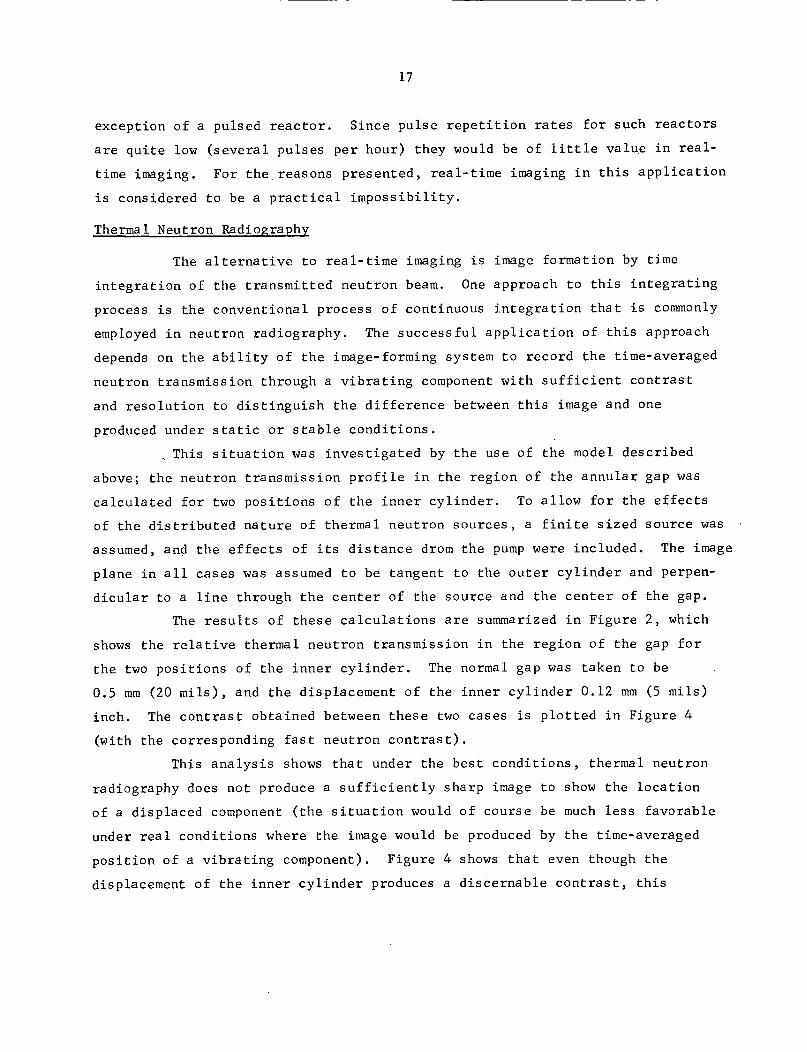
The results of these calculations are summarized in Figure 2, which
shows the relative thermal neutron transmission in the region of the gap for
the two positions of the inner cylinder. The normal gap was taken to be
0.5 mm (20 mils), and the displacement of the inner cylinder 0.12 mm (5 mils)
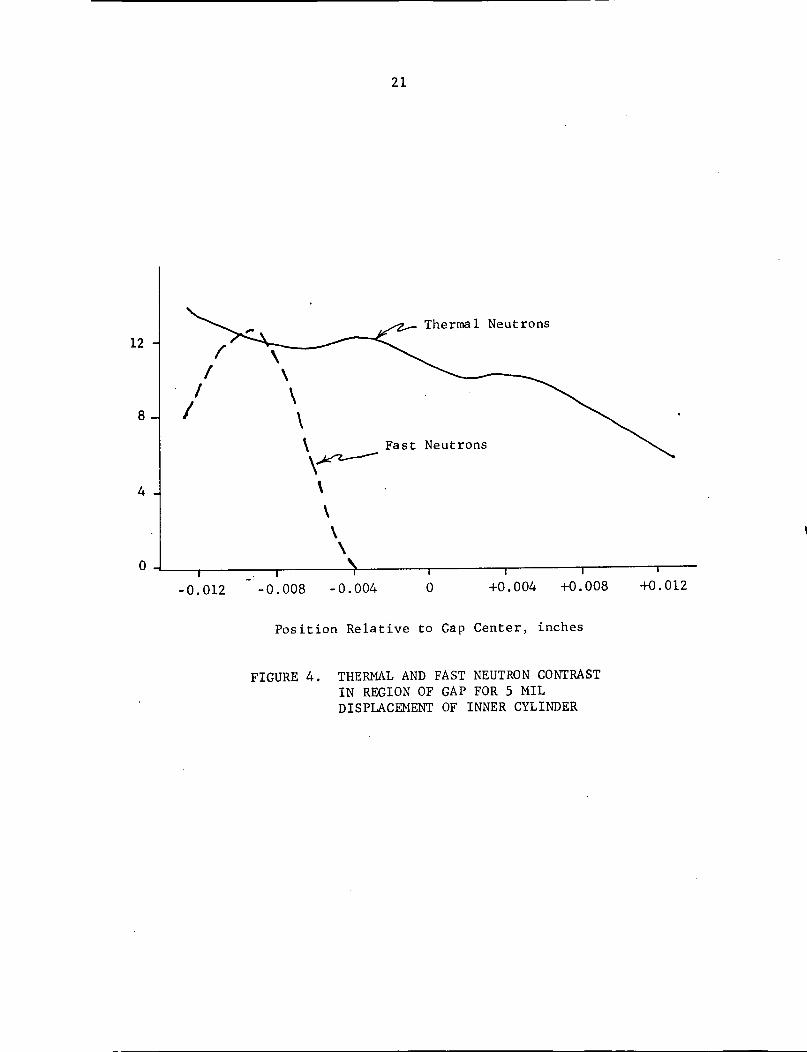
inch. The contrast obtained between these two cases is plotted in Figure 4
(with the corresponding fast neutron contrast).
This analysis shows that under the best conditions, thermal neutron
radiography does not produce a sufficiently sharp image to show the location
of a displaced component (the situation would of course be much less favorable
under real conditions where the image would be produced by the time-averaged
position of a vibrating component). Figure 4 shows that even though the
displacement of the inner cylinder produces a discernable contrast, this
18
Normal Gap >
<----a GDisplacement
*°1.24
C 1.16-
t 1.08 After Displacement
1.00 -
-0.02I I I -0.008 -0.004 0 0.004 0.008 0.012-0.012 -0.008 -0.004 0 +0.004 +0.008 +0.012
Position Relative to Gap Center, inches
FIGURE 2. THERMAL NEUTRON TRANSMISSION PROFILE
19
contrast is not associated geometrically with the displaced component. The
source geometry is responsible for this image unsharpness, and since this is
an inherent feature of thermal neutron sources, it is clear that thermal
neutron radiography is not suitable for this application.
Fast Neutron Imaging
The fact that source geometry and not the neutron absorption properties
of the components is responsible for the unsuitability of thermal neutron
radiography suggests that the use of fast neutrons might yield the required
sharpness, since fast neutron sources of extremely samll size are available.
Fast neutrons would also have the possible advantage of a somewhat higher
transmission through the pump since cross sections are lower at the higher
energy. Simply substituting fast neutrons for thermal neutrons, however,
does not improve the situation, because the efficiency of conventional
detecting and imaging methods is too low for fast neutrons. Further, the
ratio of scattering to capture cross sections is high enough for most materials
to substantially reduce contrast. A new detector concept, described below,
has been generated which holds promise to overcome these difficulties with
fast neutrons.
To assess the suitability of using fast neutrons to detect component
displacements, the calculations described above were repeated for a point
source of neutrons and with appropriate changes in neutron absorption
coefficients. The results of these calculations are shown in Figures 3 and 4.
The calculations clearly show that fast neutrons would yield significantly
more information than thermal neutrons and it appears that they would yield
sufficient information to image displacements somewhat smaller than the 0.12 mm
(5 mil) displacement used in the calculations.
The detector concept mentioned above consists simply of a long thin
tube of an organic scintillator material; the length provides the thickness
necessary to achieve a high collection efficiency, the diameter determines the
resolution, and the use of an organic material supplies the required sensitivity
to fast neutrons. Readout would be in digital form and would be achieved by
appropriate coupling of the scintillator to a light-sensitive device. An array
20
Normal Gap
Displacement
Normal Gap
1/-11 After Displacement
I I I I I I I-0.012 -0.008 -0.004 0 +0.004 +0.008 +0.012
Position Relative to Gap Center, inches
FIGURE 3. FAST NEUTRON TRANSMISSION PROFILE
1.32 1
.,
a)
EV)
E-4
C:0To
4j
w>Cr
1.24-
1.16-
1.08
1.00 _
-l
~~- 1
21
Thermal Neutrons
Fast Neutrons
I I-0.008 -0.004
-0.012 -0.008 -0.004 0I I+0.008 +0.012
+0.004 +0.008 +0.012
Position Relative to Gap Center, inches
FIGURE 4. THERMAL AND FAST NEUTRON CONTRASTIN REGION OF GAP FOR 5 MILDISPLACEMENT OF INNER CYLINDER
£/
/!!
12 -
8-
4-4
0
22
of such devices could be used to yield sufficient information to synthesize an
image, but for this particular application one or two detectors properly
positioned could probably provide the needed information. The fact that the
measurement of transmitted intensity is made with a point source and a detector
with a small area would also appear to overcome the problem of scattering.
Since the output of this device is electronic, the collection of
data could be gated and synchronized with the rotation of a turbopump and thus
provide information over selected segments of rotation. With available sources,
integration over a number of revolutions would undoubtedly be necessary;
integration over 10 seconds of pump operation is estimated to be the order
of magnitude of the time required to collect sufficient information with
available sources. A portable californium-252 source would be required. At
this time, we think that a 10-milligram source costing perhaps $10,000 would
be sufficient. Both source and detector would have to be fixed rigidly to the
pump case.
The new detection technique appears to offer the advantages of a
point source of radiation, the ability to penetrate relatively thick metal
sections, and virtually no variation of neutron cross sections with temperature.
The major disadvantage, of course, is the necessity for time-
integration to achieve a sufficiently strong signal. It may also prove
difficult to align the source and detector when applied to an actual turbo-
pump. Of course, neutron radiography cannot be used to sense position of
parts in the presence of liquid hydrogen. In any case, we believe the
technique is of sufficient promise to warrant further feasibility studies.
If approved by MSFC project personnel, we will continue our evaluation of
neutron radiography by fabricating a liquid-organic-scintillator detector and
experimentally determining sensitivity using, perhaps, a stationary shaft
whose position can be adjusted with a micrometer.
If general sensitivity is as expected, then experiments will be
conducted to determine whether it is necessary to discriminate between gamma
rays and neutrons (both will activate the scintillator material). The next
step in the feasibility will be to evaluate the effect of material interposed
between source and detector. Subsequently, application to an actual turbopump
23
could then be made. The final step in the feasibility analysis would then be
to evaluate the use of a multichannel analyzer to look at dynamic shaft position.
CONVENTIONAL DISPLACEMENT SENSORS
Basically, three kinds of techniques were evaluated in this category:
magnetic sensors, capacitance sensors, and signal transmitters which do not use
slip rings. Magnetic techniques evaluated have included sensors measuring
changes in inductance, and eddy-current sensors using either coils or Hall
elements for detection. The Bentley inductance probe is currently used to
measure deflections of turbopump components and, as such, can be considered
as the state of the art. Application of Bentley probes requires substantial
modification of a turbopump to locate the probes near the parts to be measured.
During the literature search and interviews with manufacturers,
emphasis was placed on attempting to discover techniques which could be
applied without substantial modification of the turbopumps. With the possible
exception of FM signal transmitters, no such techniques were uncovered. The
Bentley probes currently in use are, in our opinion, representative of the
state of the art of magnetic and capacitance probes as applied to turbopump
measurements.
Magnetic and Capacitance Techniques
Two kinds of magnetic sensing devices are available commercially.
Inductive probes measure the change of inductance in a coil as the gap between
the coil and the moving part changes. These require a high-conductivity
material on the moving part. Eddy-current probes measure the impedance of a
coil as influenced by eddy currents set up in the moving part. In some eddy-
current devices, a Hall element is used in place of a coil. Capacitive devices
essentially sense the change in electrical capacitance of the separating gap
between a probe and the component being measured.
24
Both magnetic and capacitive techniques share one advantage. There
are probes in each category which are highly developed and have been applied
to a wide range of applications with a wide range of environmental conditions.
One commercial capacitance probe made by Dynamic Data Corporation has actually
been in successful service at temperatures above 2000 F. Also one type,
F. W. Bell Inc.'s Hall-Pak Generators (inductive), have demonstrated successful
operation at cryogenic temperatures. Several of Dynamic Data's high-temperature
capacitance probes were recently operated at liquid nitrogen temperatures and
apparently performed well and also did not suffer any permanent damage. It
must be borne in mind, however, that the capacitance method is only feasible
if no changes in the dielectric occur in the gap. This could be a limitation
if the gap contains alternately liquid and gas or a mixture of these. This
could pertain if cavitation occurs. A capacitive transducer face consists
of concentric electrodes separated by an insulating material; because these
materials are of different hardnesses there is the likelihood of differential
wear in the event of cavitation or simply the erosive action of the high-
velocity fluid. Such wear would be likely to change the contour of the probe
face, and to some extent alter the calibration of the system. In addition,
any roughening of the surface would be apt to increase the tendency for turbulence
and more violent cavitation. Such a situation is self-aggravating and must
lead to premature, and possibly rapid failure of the transducer. Overcoming
this difficulty would involve a judicious selection of materials for probe
components and/or coating the sensing face with a durable dielectric film--e.g.,
a sprayed-on ceramic. Another problem would be sealing of the probe and its
concentric electrodes against leakage of the 7000 psi cryo-fluid. This also
requires proper materials selection plus possible design improvements to
produce an adequate strength as well as a minimum elastic deformation under
pressure.
The inductive techniques are inherently more attractive because
measurements are not affected by changes, such as cavitation, in the gap
region being measured. Even the presence of a medium of low conductivity in
the gap can be tolerated. One manufacturer, F. W. Bell, produces Hall effect
magnetic field sensors which can be used to - 269 C, apparently other manufac-
turers have not yet attacked the cryogenic applications. In any event the
25
selection of materials having low coefficients of conductivity and of
permeability at cryo temperatures appears quite feasible. The other problem--
differential thermal expansion effects--should prove somewhat less difficult
to overcome than was the case for development of transudcers capable of
operation at high temperatures. The Hall-effect type of pickup cannot be
exposed to temperatures in excess of - 150 C; in fact, they begin to lose
calibration above - 105 C. Other conventional types of inductive transducers
have been applied in ambient temperature fields up to - 1500 F.
Mechanical Technology Inc. have designed and successfully operated
transducers using ceramic insulated gold wire wound on a ceramic form. These
coils have been subjected to many temperature cycles to 1500 F with no
detectable degradation in the coil electrical properties. The subsequently
manufactured transducer was fully encapsulated with all welded joints. This
points up an inherent advantage to employing inductive transducers, the
sensing function can be accomplished through a metallic sheating or bulkhead.
Thus, no roughening or differential wear or erosion rates need to be anticipated
(the situation described above for the capacitative types). This construction
feasture also protects the internal transducer parts from the high-pressure
environment. The presence of pressure-produced mechanical deflections which
would change transducer calibration might pose a problem for the hermetically
sealed capsule design. Application over a broad temperature range could
also be expected to produce calibration changes, but optimization should be
feasible.
Nonslip-Ring Signal Transmission
Consideration heretofore has been with respect to sensing techniques
which do not require contact with the moving part under surveillance. A more
common approach, used in the past, is the application of accelerometers,
strain gages, and thermocouples to the moving part. Transmission of the low
power output signals from these sensors through slip-ring contacts however,
has been unsatisfactory for high-speed rotating machinery because of wear and
unreliable performance. Recently telemetry hardware has been developed for
application to high-speed rotating equipment. An example of the refinement
26
attained for such equipment is evidenced in the Aerotherm Corporation
telemetry systems. Tiny transmitters potted to withstand 30,000 g at 125 C,
are fitted into compartments in a hollow shaft or rotating support ring.
The transmitters are powered by a transformer or batteries, and communicate
via a modulated carrier wave to a stationary (and circular) antenna mounted
about one-eighth inch away. These low-level signals are carried via co-ax
cable to the receiver-amplifier and hence to a data readout or recording device.
At present, transmitters are cylindrical, 5/8 inch x 1-1/8 inches in diameter;
or rectangular, 9/16 inch square x 1-3/8 inch long. One transmitter is used
for each signal; however, the manufacturer is currently developing a multiplexing
system which will handle eight signals simultaneously.
The use of a signal transmitter appears to us to be an attractive
way to do away with the disadvantages of contact-type slip rings. For best
results, however, the use of a system in which the rotating and stationary
components are very close together would be required. In the case of a
turbopump, this would imply that the turbopump design should allow a stationary
pickup to fit inside a hollow pump shaft. Such a requirement might be a
severe restriction on pump design. In any case, the use of a signal transmitter
solves only half the problem. Sensors must still be located at the points of
interest.
DISCUSSION
With the exception of the new fast-neutron detection technique
which remains to be evaluated, the feasibility study of Phase I has resulted
in three techniques which appear feasible for the turbopump applications.
(1) Ultrasonic Doppler
(2) Flash X-ray
(3) Light-pipe reflectance.
These three techniques, by mutual agreement between BCL and NASA-MSFC project
personnel, have been advanced into Phase II.
It is clear that none of the three techniques will be able to make
all the measurements of interest. An ultrasonic Doppler device will be
limited to applications where a solid or liquid path can be devised into
the part to be measured from the source. This appears to remove the turbine
27
section from its capability, because of cooling channels around the blades.
On the other hand, the flash X-ray appears capable of measurements in the
turbine section where metal sections are thin, and appears questionable
in the pump section where heavy metal sections exist. If the fast-neutron
technique proves feasible, it should be able to sense motions in the pump
section. The light-pipe-reflectance device appears somewhat limited in high-
temperature capability, so it is not expected to be applicable to the turbine
blades (although probably applicable at turbine-wheel temperatures).
It is possible, therefore, that a combination of the various
techniques may be desirable. -For instance, a flash X-radiograph might be
taken first to obtain diagnostic information regarding several turbopump
components. Subsequently, one or more ultrasonic or optical sensors might
be fitted on the pump to measure only the most critical components.
Obviously, the specific advantages and disadvantages of the three
feasible techniques cannot be determined accurately until Phase II has been
concluded. The feasibility study has, however, illuminated some of the
characteristics of each. These are listed below.
Ultrasonic Doppler Devices
Advantages
(1) Only minor pump modification needed
(2) Ability to sense motion of parts far
inside the pump
(3) Apparent capability of sensing the entire
range of motions anticipated: displacements
from 2.5 microns (0.1 mils) to 0.5 mm (20 mils),
frequencies to 100,000 cpm
(4) Capability of sonic analysis
(5) Real-time, instant readout.
Disadvantages
(1) Requirement of "solid" acoustical path
(2) Need for complex instrumentation to permit
vibrational amplitude and frequency to be
inferred from Doppler velocity
28
(3) Need for direct calibration for some
components
(4) Sensitivity of acoustical properties of
materials to rapid temperature changes
(not a problem for gradual temperature
changes).
Flash X-Ray
Advantages
(1) Noncontacting; very little pump modification
required
(2) Diagnostic capability; can view several
components at once
(3) Can be pulsed to detect motions as
rapid as 35,000 cpm.
Disadvantages
(1) Cannot penetrate extremely dense sections
(2) Is not instant reading
(3) May not be able to detect displacements
smaller than 25 microns (1 mil)
(4) Line of sight may be limited by pump
support structure.
Light-Pipe-Reflectance
Advantages
(1) Basic unit is already developed
(2) Light fibers can be bent to make
installation easier
(3) Can sense both small displacements
on the order of tenths of microns
and large displacements on the
order of millimeters
(4) Probable temperature capability from -400 F
to 1200 F
29
(5) Frequency response up to 2 x 10⁶ cpm.
Disadvantages
(1) Requires modification of turbopump.
FUTURE WORK
The first step in Phase II will be to set up the J-2 turbopump at
BCL and to make it capable of being externally driven at moderate speeds.
Subsequently, each of the three techniques will be applied to various
components to determine the specific problems posed by an actual turbopump.
with this information available, experimental work will be undertaken to
develop each technique with respect to the turbopump requirements.
Future plans to evaluate the fast-neutron detector are detailed in
the section dealing with neutron radiography.
COST DATA
Contract value less fee - $87,752
Approximate actual expenditures as of August 1, 1971 - $22,210
Estimated expenditures for August - $3650
Estimated funds to completion - $61,892
Anticipated over/under run - none
Changes - none.
No schedule problems are foreseen at this time.
30
MONTHLY AND QUARTERLY PROGRESS REPORT DISTRIBUTION LIST
No. Copies
National Aeronautics and Space AdministrationGeorge C. Marshall Space Flight CenterMarshall Space Flight Center, Alabama 35812Attention Contracting Officer (A&TS-PR-MB) 1
National Aeronautics and Space AdministrationGeorge C. Marshall Space Flight CenterMarshall Space Flight Center, Alabama 35812Attention Management Services (A&TS-MS-IL) 1
Security Office (A&TS-MS-S) 1Mr. Forrest Pitsenberger (S&E-ASTN-EPS)
Technical Manager 5Mr. B. Birdwell (S&E-ASTN-RRI) 1Mr. H. Attaya (S&E-R-R) 1
National Aeronautics and Space AdministrationAssistant Director for Propulsion, OART, Code RPWashington, D.C. 20546Attention Dr. Robert Levine 2
National Aeronautics and Space AdministrationLewis Research Center21000 Brookpark RoadCleveland, Ohio 41135Attention Mr. Irvin Johnsen 1
Captain Robert ProbstEngineering Development BranchAir Force Rocket Propulsion LaboratoryEdwards, California 93523 1
Jet Propulsion LaboratoryLiquid Propulsion Section4800 Oak Grove DrivePasadena, California 91103 1
National Aeronautics and Space AdministrationWashington, D.C. 20546Attention Dr. Eldon Hall, Code MTG 1
Mr. Stanley E. WriteDefense Supply AgencyDCASR-ClevelandOffice of Engineering-DCRO-Y1240 E. 9th StreetCleveland, Ohio 44199 1
Scientific and Technical Information FacilityP. O. Box 33College Park, Maryland 20740Attention NASA Representative, Code CRT 1