Aktiv-Subwoofer-Modul Active Subwoofer Module · Subwoofer nach Anweisung optimal angepasst werden...
36
ELECTRONICS FOR SPECIALISTS ELECTRONICS FOR SPECIALISTS ELECTRONICS FOR SPECIALISTS ELECTRONICS FOR SPECIALISTS SAM-2 Bestell-Nr. • Order No. 32.0670 Aktiv-Subwoofer-Modul Active Subwoofer Module BEDIENUNGSANLEITUNG INSTRUCTION MANUAL MODE D’EMPLOI ISTRUZIONI PER L’USO GEBRUIKSAANWIJZING MANUAL DE INSTRUCCIONES INSTRUKCJA OBSŁUGI SIKKERHEDSOPLYSNINGER SÄKERHETSFÖRESKRIFTER TURVALLISUUDESTA
Transcript of Aktiv-Subwoofer-Modul Active Subwoofer Module · Subwoofer nach Anweisung optimal angepasst werden...

ELECTRONICS FOR SPECIALISTS ELECTRONICS FOR SPECIALISTS ELECTRONICS FOR SPECIALISTS ELECTRONICS FOR SPECIALISTS
SAM-2Bestell-Nr. • Order No. 32.0670
Aktiv-Subwoofer-ModulActive Subwoofer Module
BEDIENUNGSANLEITUNG
INSTRUCTION MANUAL
MODE D’EMPLOI
ISTRUZIONI PER L’USO
GEBRUIKSAANWIJZING
MANUAL DE INSTRUCCIONES
INSTRUKCJA OBSŁUGI
SIKKERHEDSOPLYSNINGER
SÄKERHETSFÖRESKRIFTER
TURVALLISUUDESTA


3
ELECTRONICS FOR SPECIALISTS ELECTRONICS FOR SPECIALISTS ELECTRONICS FOR SPECIALISTS ELECTRONICS FOR SPECIALISTS
Deutsch . . . . . . . . . . Seite 4
English . . . . . . . . . . . Page 8
Français . . . . . . . . . . Page 12
Italiano . . . . . . . . . . . Pagina 16
Nederlands . . . . . . . Pagina 20
Español . . . . . . . . . . Página 24
Polski . . . . . . . . . . . . Strona 28
Dansk . . . . . . . . . . . . Sida 33
Svenska . . . . . . . . . . Sidan 33
Suomi . . . . . . . . . . . . Sivulta 34

4
Deu
tsch
EnglishEnglish Page
FrançaisFrançais Page
ItalianoItaliano Pagina
EspañolEspañol Página
NederlandsNederlands Pagina
PolskiPolski Strona
SUBLEVEL
GREEN – ONRED – STAND-BY
SUBCROSSOVER LEVEL
SUBPHASE
SATCROSSOVER
100HzFREQUENCY
40Hz
SUB-BOOST
GROUNDLIFT
POWER
LINE IN SAT OUT230V~ / 50 Hz / 300VA
HIGH LEVEL INPUT
LEFT RIGHT
RIGHT
LEFT
SAM-2 ACTIVE SUBWOOFER MODULE
T3.15AL
MIN MAX 50Hz 150Hz 0 0 180 30Hz 50Hz 50Hz 150Hz
100Hz
GND LIFT
250 W MAX • 200 W RMS / 4 Ω • 125 W RMS / 8 Ω
+ 6dB ° °
14 15
13
9
3 4 5 6 7 8
1
11
10
12
2
Aktiv-Subwoofer-ModulDiese Anleitung richtet sich an Anwender mit Grundkenntnissen in der Elektronik . Bitte lesen Sie die Anleitung vor dem Betrieb gründlich durch und heben Sie sie für ein späteres Nachlesen auf .
1 Übersicht1 Kühlkörper, kann im Betrieb unter Volllast bis
60 °C heiß werden Der Kühlkörper muss ungehindert Wärme ab-strahlen können . Bei Überhitzung schaltet das Modul auf Stand-by .
2 LED für den Betriebszustandrot = Stand-by (Bereitschaft)grün = Endstufe eingeschaltet
3 Regler SUB LEVEL zum Einstellen der Lautstärke
4 Regler SUB CROSSOVER zum Einstellen der oberen Grenzfrequenz für den Subwoofer
5 Regler SUB-BOOST FREQUENCY zum Einstellen der Frequenz für die Bassanhebung
6 Regler SUB-BOOST LEVEL zum Einstellen der Bassanhebung bis maximal +6 dB
7 Regler SUB PHASE zum Einstellen der Phasen-lage für den Subwoofer
8 Regler SAT CROSSOVER zum Einstellen der unteren Grenzfrequenz des Hochpasses für den Ausgang SAT OUT (15)
9 Groundlift-SchalterTaste nicht gedrückt Signalmasse und Frontplatte / Schutzleiter
sind getrennt
Taste gedrückt Signalmasse und Frontplatte / Schutzleiter
sind elektrisch verbunden10 Ein-/Ausschalter POWER11 Netzbuchse zum Anschluss an eine Steckdose
(230 V/50 Hz) über das beiliegende Netzkabel12 Sicherungshalter;
eine durchgebrannte Sicherung nur durch eine gleichen Typs ersetzen
13 Buchsen HIGH LEVEL INPUT für den Signalein-gang zum Anschluss an die Lautsprecheraus-gänge eines Endverstärkers; alternativ zu den Cinch-Buchsen LINE IN (14)
14 Cinch-Buchsen LINE IN für ein Eingangssignal mit Line-Pegel; alternativ zu den Buchsen HIGH LEVEL IN PUT (13)
15 Cinch-Buchsen SAT OUT, Signalausgang mit Line-Pegel zum Anschluss an eine Stereoend-stufe für die Satellitenlautsprecher
2 Hinweise für den sicheren Gebrauch
Das Modul entspricht allen relevanten Richtlinien der EU und trägt deshalb das -Zeichen .
WARNUNG Das Modul wird mit lebensgefähr-licher Netzspannung betrieben . Achten Sie beim Einbau in eine Lautsprecherbox unbedingt darauf, dass das Modul nicht mit der Netz-
spannung verbunden ist . Den Netzstecker aus der Steckdose ziehen! Anderenfalls besteht die Gefahr eines lebensgefährlichen Schlages .
DeutschDeutsch Seite

5
Deu
tsch• Das Modul ist nur zur Verwendung im Innen-
breich geeignet . Schützen Sie es vor Tropf- und Spritzwasser, hoher Luftfeuchtigkeit und Hitze (zulässiger Einsatztemperaturbereich 0 – 40 °C) .
• Stellen Sie keine mit Flüssigkeit gefüllten Ge-fäße, z . B . Trinkgläser, auf die Lautsprecherbox .
• Nach dem Einbau des Moduls wird die in der Lautsprecherbox entstehende Wärme durch die Kühlrippen (1) abgegeben . Decken Sie diese deshalb nicht ab . Stellen Sie die Box nie direkt an eine Wand; halten Sie einen entsprechenden Abstand ein .
• Nehmen Sie das Modul nicht in Betrieb und zie-hen Sie sofort den Netzstecker aus der Steckdose:1 . wenn sichtbare Schäden am Modul oder an
der Netzanschlussleitung vorhanden sind,2 . wenn nach einem Sturz oder Ähnlichem der
Verdacht auf einen Defekt besteht,3 . wenn Funktionsstörungen auftreten .Lassen Sie das Modul in jedem Fall in einer Fach-werkstatt reparieren .
• Ziehen Sie den Netzstecker nie am Kabel aus der Steckdose, fassen Sie immer am Stecker an .
• Verwenden Sie für die Reinigung nur ein tro-ckenes, weiches Tuch, niemals Wasser oder Chemikalien .
• Wird das Modul zweckentfremdet, nicht richtig montiert, falsch angeschlossen bzw . bedient oder nicht fachgerecht repariert, kann keine Haftung für daraus resultierende Sach- oder Personenschäden und keine Garantie für das Modul übernommen werden .
Soll das Modul endgültig aus dem Betrieb genommen werden, übergeben Sie es zur umweltgerechten Entsorgung einem örtlichen Recyclingbetrieb .
3 VerwendungsmöglichkeitenDas Einbaumodul SAM-2 ist eine komplett auf-gebaute 200-W-Verstärkerendstufe mit Netzteil und für den Einbau in eine 4-Ω- oder 8-Ω-Laut-sprecherbox konzipiert . Durch die integrierte 18-dB- Subwoofer-Frequenzweiche lässt sich eine Aktiv- Subwoofer-Box realisieren . Das Modul und der angeschlossene Lautsprecher werden durch ein 24-dB-Subsonic-Filter und umfassende Schutz-schaltungen geschützt .
Der besondere Vorteil des SAM-2 ist, dass es als fertig montierter Aktiv-Subwoofer an jeder Stelle im Hörraum aufgestellt werden kann . Durch Regler für den Pegel und die Phasenlage lässt es sich optimal an die Satellitenlautsprecher anpassen .
4 MontageWARNUNG
Während der Montage darf das Modul auf keinen Fall mit der Netz-spannung verbunden sein!
1) Für den Einbau des Moduls in die Lautsprecher-box einen Ausschnitt von 155 × 340 mm sägen . Die erforderliche Einbautiefe beträgt bei nicht versenkter Frontplatte 85 mm .
2) Es dürfen nur Lautsprecher bzw . Lautsprechersys-teme mit einer Gesamtimpedanz von mindestens 4 Ω angeschlossen werden . Den Lautsprecher über Flachstecker mit den Anschlüssen OUT+ und OUT− links oben auf der Leiterplatte der Endstufe verbinden (siehe Seite 35) . Dabei auf die richtige Polung achten, d . h . den Lautspre-cherpluspol an den Kontakt OUT+ anschließen .
3) Das Modul mit zehn M4-Schrauben an der Box festschrauben .
5 Geräte anschließenVor dem Anschluss bzw . vor dem Ändern beste-hender Anschlüsse die Aktivbox ausschalten .
5.1 EingängeDas Modul SAM-2 hat zwei Eingänge zur Ver-fügung:1 . Die Cinch-Buchsen LINE IN (14) für Signale mit
Line-Pegel zum Anschluss von z . B . Vorverstärker, Mischpult, Equalizer, Effektgerät usw .
2 . Die Apparatebuchsen HIGH LEVEL INPUT (13) für den Anschluss an die Lautsprecherausgänge eines Endverstärkers . Wichtig: Werden die Apparatebuchsen verwen-det, darf die Ausgangsleistung des angeschlos-senen Endverstärkers nicht 480 W pro Kanal an 4-Ω-Lautsprechern bzw . 240 W pro Kanal an 8-Ω-Lautsprechern überschreiten, sonst kommt es durch Übersteuerung zu Signalverzerrungen .
Am einfachsten und sichersten ist der Anschluss an den Buchsen LINE IN (14) . Nur wenn kein Line- Signal zur Verfügung steht, sollten die Eingänge HIGH LEVEL INPUT (13) verwendet werden . Diese Eingänge über Lautsprecherkabel an die Lautspre-cherausgänge eines Endverstärkers anschließen .
Vorsicht beim Anschluss über die Apparatebuchsen!a . Bei Endverstärkern mit einer höheren Ausgangs-
leistung als oben angegeben, liegt berührungs-gefährliche Spannung an den Buchsen HIGH LEVEL INPUT an .

6
Deu
tsch
SUBLEVEL
GREEN – ONRED – STAND-BY
SUBCROSSOVER LEVEL
SUBPHASE
SATCROSSOVER
100HzFREQUENCY
40Hz
SUB-BOOST
GROUNDLIFT
POWER
LINE IN SAT OUT230V~ / 50 Hz / 300VA
HIGH LEVEL INPUT
LEFT RIGHT
RIGHT
LEFT
SAM-2 ACTIVE SUBWOOFER MODULE
T3.15AL
MIN MAX 50Hz 150Hz 0 0 180 30Hz 50Hz 50Hz 150Hz
100Hz
GND LIFT
250 W MAX • 200 W RMS / 4 Ω • 125 W RMS / 8 Ω
+ 6dB ° °
14 15
13
9
3 4 5 6 7 8
1
11
10
12
2
b . Bei einem versehentlichen Kurzschluss kann der Endverstärker beschädigt werden .
c . Beim Anschluss auf die richtige Polung achten: Jeweils den Pluspol (gekennzeichnete Lautspre-cherkabelader) mit der roten Apparatebuchse verbinden .
5.2 AusgängeDie Cinch-Buchsen SAT OUT (15) mit den Eingän-gen einer Stereoendstufe verbinden, welche die Satellitenlautsprecher betreibt .
Bei hochwertigen, auftrennbaren Vollverstär-kern mit einem geregelten Vorverstärker-Ausgang (mögliche Beschriftung „Pre Out“) und einem End-stufen-Eingang (mögliche Beschriftung „Amp In“) kann das Modul SAM-2 auch in den Vollverstärker eingeschleift werden: Die Buchsen LINE IN (14) an den Vorverstärker-Ausgang anschließen und die Buchsen SAT OUT (15) an den Endstufen-Eingang .
5.3 StromversorgungZum Schluss das beiliegende Netzkabel zuerst in die Netzbuchse (11) stecken und dann in eine Steck-dose (230 V/ 50 Hz) .
6 BedienungAlle Einstellungen und Klangbeurteilungen können nur in Verbindung mit den Satellitenlautsprechern erfolgen . Der Klang sollte am endgültigen Hörplatz beurteilt und durch eine zweite Person am Aktiv- Subwoofer nach Anweisung optimal angepasst werden .
1) Mit dem Schalter POWER (10) die Aktivbox ein-schalten . Solange kein Eingangssignal anliegt, ist die Box im stromsparenden Bereitschaftsmodus (Stand-by) und die Kontroll-LED (2) leuchtet rot . Sobald ein Signal anliegt, schaltet die Endstufe ein und die LED leuchtet grün .
Liegt länger als ca . 7 Minuten kein Signal an, schaltet die Aktivbox wieder auf Bereitschaft zurück (LED = rot) . Wird die Aktivbox längere Zeit nicht benutzt, sollte sie mit dem Schalter POWER ausgeschaltet werden . Anderenfalls wird im Bereitschaftsmodus stets ein geringer Strom verbraucht .
Sollte das automatische Umschalten zwi-schen Stand-by und Betrieb nicht optimal funk-tionieren, lässt sich die Einschaltschwelle im Be-reich von 1 – 10 mV verändern . Der Regler für die Einschaltschwelle befindet sich in der Position RVa auf der Vorverstärker-Leiterplatte (siehe Seite 35) . Je weiter der Regler im Uhrzeiger-sinn gedreht wird, desto höher muss der Ein-gangspegel sein, bei dem das Modul einschaltet .
2) Ist durch den Anschluss eine Masseschleife ent-standen, tritt ein Brummen auf (z . B . bei leisen Musikpassagen) . Diese Masseschleife lässt sich mit dem Groundlift-Schalter (9) unterbrechen . Anderseits ist der Verstärker nicht gegen elekt-rische Störfelder abgeschirmt, wenn die Front-platte nicht an Masse liegt . Im Zweifelsfall den Schalter wechselweise schalten, um die optimale Einstellung zu finden .
3) Mit dem Regler SUB CROSSOVER (4) die Trenn-frequenz für den Subwoofer einstellen, d . h . die

7
Deu
tschFrequenz, die nicht mehr durch den Subwoo-
fer wiedergegeben werden soll (je niedriger die Trennfrequenz, desto schwerer die akustische Ortung des Subwoofers; je höher die Trennfre-quenz, desto stärker die Bassunterstützung) . In den meisten Fällen werden Regal- und kleine Standlautsprecher optimal ergänzt, wenn die eingestellte Trennfrequenz zwischen 60 Hz und 100 Hz liegt .
4) Das Lautstärkeverhältnis zu den übrigen Laut-sprechern mit dem Regler SUB LEVEL (3) ein-stellen . So lässt sich eine natürliche oder eine bewusst verstärkte Basswiedergabe einstellen .
5) Die Phasenlage für den Subwoofer mit dem Reg-ler SUB PHASE (7) einstellen . Diese Einstellung ist je nach den akustischen Gegebenheiten stär-ker oder schwächer wahrnehmbar . Am besten lässt sich die Einstellung bei einem Musikstück mit einem E-Bass, einem Kontrabass oder einer tiefen Bassstimme vornehmen . Den Regler SUB PHASE auf lauteste Basswiedergabe einstellen . Danach bei Bedarf den Regler SUB LEVEL wieder etwas zurückdrehen .
6) Mit dem Regler SUB-BOOST LEVEL (6) können bestimmte Frequenzen im Tiefbassbereich bis zu 6 dB angehoben werden . Die Frequenz für die Bassanhebung mit dem Regler SUB-BOOST FREQUENCY (5) einstellen .
7) Mit dem Regler SAT CROSSOVER (8) die Trenn-frequenz für die Satellitenlautsprecher einstel-len, d . h . die Frequenz, die nicht mehr durch die Satellitenlautsprecher wiedergegeben werden soll . Dadurch wird der Verstärker für die Satel-litenlautsprecher von den tiefen Frequenzen entlastet .
7 SchutzschaltungenZum Schutz der Endstufe des SAM-2 und des angeschlossenen Subwoofers sind verschiedene Schutzschaltungen vorhanden:1 . Bei einem Kurzschluss oder einer Gleichspan-
nungsüberlagerung am Ausgang für den Sub-woofer schaltet das Modul sofort auf Stand-by . Das Modul mit dem Schalter POWER (10) aus-schalten und die Fehlerursache durch Fachper-sonal beheben lassen . Die Schutzschaltung wird durch das Ausschalten zurückgesetzt .
2 . Bei Überhitzung schaltet das Modul ebenfalls auf Stand-by . Der Kühlkörper (1) muss besser belüftet werden . Nach dem Abkühlen auf nor-male Betriebstemperatur schaltet das Modul wieder ein .
8 Technische DatenSinusausgangsleistung an 4-Ω-Lautsprecher: � � � � 200 W an 8-Ω-Lautsprecher: � � � � 125 WMusikausgangsleistung an 4-Ω-Lautsprecher: � � � � 250 W an 8-Ω-Lautsprecher: � � � � 180 W
Frequenzbereich Subwoofer-Ausgang untere Grenzfrequenz: � � 20 Hz obere Grenzfrequenz: � � 50 – 150 Hz einstellbar Ausgang SAT OUT untere Grenzfrequenz: � � 50 – 150 Hz einstellbar obere Grenzfrequenz: � � 20 kHz
Tiefbassanhebung: � � � � � � � � bis +6 dB / 30 – 50 Hz
Klirrfaktor: � � � � � � � � � � � � � � < 0,1 %
Störabstand: � � � � � � � � � � � � > 70 dB
min� Anschlussimpedanzfür den Subwoofer: � � � � � � � 4 Ω
Eingänge LINE IN: � � � � � � � � � � � � � � max� 4,2 V/ 20 kΩ HIGH LEVEL INPUT: � � � � � max� 44 V/ 17 kΩ
entspricht 480 W an 4 Ω bzw� 240 W an 8 Ω
Stromversorgung: � � � � � � � � 230 V/ 50 Hz
Leistungsaufnahme bei Volllast: � � � � � � � � � � � 300 VA im Leerlauf: � � � � � � � � � � � 19 VA in Stand-by: � � � � � � � � � � � 6 VA
Einschaltautomatik Einschaltschwelle: � � � � � � 1 – 10 mV Stand-by-Aktivierung: � � � nach ca� 7 Minuten ohne
Eingangssignal
Einsatztemperatur: � � � � � � � � 0 – 40 °C
Abmessungen (B × H × T): � � 185 × 370 × 89 mm
erforderl� Boxenausschnitt: � � 155 × 340 mm
Einbautiefe ohne Frontplatte: 85 mm
Gewicht: � � � � � � � � � � � � � � � 4,9 kg
Änderungen vorbehalten .
Diese Bedienungsanleitung ist urheberrechtlich für MONACOR ® INTERNATIONAL GmbH & Co. KG geschützt. Eine Reproduktion für eigene kommerzielle Zwecke – auch auszugsweise – ist untersagt.

8
EnglishDeutsch
Deutsch Seite
FrançaisFrançais Page
ItalianoItaliano Pagina
EspañolEspañol Página
NederlandsNederlands Pagina
PolskiPolski Strona
SUBLEVEL
GREEN – ONRED – STAND-BY
SUBCROSSOVER LEVEL
SUBPHASE
SATCROSSOVER
100HzFREQUENCY
40Hz
SUB-BOOST
GROUNDLIFT
POWER
LINE IN SAT OUT230V~ / 50 Hz / 300VA
HIGH LEVEL INPUT
LEFT RIGHT
RIGHT
LEFT
SAM-2 ACTIVE SUBWOOFER MODULE
T3.15AL
MIN MAX 50Hz 150Hz 0 0 180 30Hz 50Hz 50Hz 150Hz
100Hz
GND LIFT
250 W MAX • 200 W RMS / 4 Ω • 125 W RMS / 8 Ω
+ 6dB ° °
14 15
13
9
3 4 5 6 7 8
1
11
10
12
2EnglishEnglish Page
Active Subwoofer ModuleThese instructions are intended for users with basic electronic knowledge . Please read the instructions carefully prior to operation and keep them for later reference .
1 Overview1 Heat sink, may heat up to 60 °C under full load
The heat sink must be allowed to dissipate heat without any obstruction . In case of overheating, the module will go on stand-by .
2 LED to indicate the operating modered = stand-bygreen = power amplifier switched on
3 Control SUB LEVEL for adjusting the volume
4 Control SUB CROSSOVER for adjusting the upper crossover frequency for the subwoofer
5 Control SUB-BOOST FREQUENCY for adjusting the frequency for the bass boost
6 Control SUB-BOOST LEVEL for adjusting the bass boost up to +6 dB max .
7 Control SUB PHASE for adjusting the phase for the subwoofer
8 Control SAT CROSSOVER for adjusting the lower crossover frequency of the high pass for the output SAT OUT (15)
9 Groundlift switchbutton not pressed signal ground and front plate/earthed con-
ductor are separated
button pressed signal ground and front plate / earthed con-
ductor are electrically connected10 POWER switch11 Mains jack for connection to a mains socket
(230 V/ 50 Hz) via the supplied mains cable12 Fuse support;
always replace a blown fuse by one of the same type
13 Jacks HIGH LEVEL INPUT for the signal input for connection to the speaker outputs of a power amplifier; as an alternative to the RCA jacks LINE IN (14)
14 RCA jacks LINE IN for an input signal with line level; as an alternative to the jacks HIGH LEVEL INPUT (13)
15 RCA jacks SAT OUT, signal output with line level for connection to a stereo power amplifier for the satellite speakers
2 Safety NotesThe module corresponds to all relevant directives of the EU and is therefore marked with .
WARNING The module uses dangerous mains voltage . Never connect the module to the mains voltage when installing it into a speaker cabinet . Disconnect
the plug from the mains socket, otherwise you will risk an electric shock which may be dangerous to life!
• The module is suitable for indoor use only . Pro-tect it against dripping water and splash water,

9
Englishhigh air humidity and heat (admissible ambient
temperature range: 0 – 40 °C) .
• Do not place any vessel filled with liquid on the unit, e . g . a drinking glass .
• When the module has been installed, the heat generated in the speaker cabinet is carried off by the cooling fins (1) . Therefore, never cover the cooling fins . Never place the cabinet directly on a wall; always keep a sufficient distance .
• Do not operate the module or immediately dis-connect the plug from the mains socket1 . if there is visible damage to the module or to
the mains cable,2 . if a defect might have occurred after the unit
was dropped or suffered a similar accident,3 . if malfunctions occur .In any case the unit must be repaired by skilled personnel .
• Never pull the mains cable when disconnecting the mains plug from the socket, always seize the plug .
• For cleaning only use a dry, soft cloth; never use chemicals or water .
• No guarantee claims for the module or liability for any resulting personal damage or material damage will be accepted if the module is used for other purposes than originally intended, if it is not correctly installed, connected or operated, or if it is not repaired in an expert way .
If the module is to be put out of opera-tion definitively, take it to a local recycling plant for a disposal which is not harmful to the environment .
3 ApplicationsThe insertion module SAM-2 is a fully assembled 200 W power amplifier with integrated power supply unit designed for installation into 4 Ω or 8 Ω speaker cabinets . Due to the integrated 18 dB subwoofer crossover network, an active subwoofer system can be created . The module and the speaker connected are protected by a 24 dB subsonic filter and comprehensive protective circuits .
It is the particular advantage of SAM-2 that it can be placed anywhere in the room as a fully assembled active subwoofer . Level and phase controls allow optimum matching to the satellite speakers .
4 InstallationWARNING
During installation, the module must never be connected to the mains voltage!
1) For installing the module into the speaker cabi-net, saw a cutout of 155 × 340 mm . If the front panel is not recessed, the required mounting depth is 85 mm .
2) Only connect speakers or speaker systems with a total impedance of at least 4 Ω . Use push-on terminals to connect the speaker to the connec-tions OUT+ and OUT− on the top left of the PCB of the power amplifier (see page 35) . Observe the correct polarity, i . e . connect the positive pole of the speaker to the contact OUT+ .
3) Use ten M4 screws to screw the module to the cabinet .
5 ConnectionAlways switch off the active speaker system prior to making or changing any connections .
5.1 InputsThe module SAM-2 is equipped with two inputs:1 . The RCA jacks LINE IN (14) for signals with line
level for connecting e . g . preamplifier, mixer, equalizer, effect unit, etc .
2 . The binding posts HIGH LEVEL INPUT (13) for connection to the speaker outputs of a power amplifier . Important: If the binding posts are used, the out-put power of the power amplifier connected must not exceed 480 W per channel at 4 Ω speakers or 240 W per channel at 8 Ω speakers, otherwise there will be signal distortions due to overload .
Connection to the jacks LINE IN (14) is the easiest and safest solution . The inputs HIGH LEVEL INPUT (13) should only be used if no line signal is available . Use speaker cables to connect these inputs to the speaker outputs of a power amplifier .
Be careful when connecting via the binding posts!a . In case of power amplifiers with a higher out-
put power than indicated above, there will be a hazard of contact with dangerous voltage at the jacks HIGH LEVEL INPUT .
b . In case of accidental short circuit, the power amplifier may be damaged .
c . Observe the correct polarity for connection: Con-nect the corresponding positive pole (speaker cable core with marking) to the red binding post .

10
English
SUBLEVEL
GREEN – ONRED – STAND-BY
SUBCROSSOVER LEVEL
SUBPHASE
SATCROSSOVER
100HzFREQUENCY
40Hz
SUB-BOOST
GROUNDLIFT
POWER
LINE IN SAT OUT230V~ / 50 Hz / 300VA
HIGH LEVEL INPUT
LEFT RIGHT
RIGHT
LEFT
SAM-2 ACTIVE SUBWOOFER MODULE
T3.15AL
MIN MAX 50Hz 150Hz 0 0 180 30Hz 50Hz 50Hz 150Hz
100Hz
GND LIFT
250 W MAX • 200 W RMS / 4 Ω • 125 W RMS / 8 Ω
+ 6dB ° °
14 15
13
9
3 4 5 6 7 8
1
11
10
12
2
5.2 OutputsConnect the RCA jacks SAT OUT (15) to the inputs of a stereo power amplifier operating the satellite speakers .
In case of separable full amplifiers of high qual-ity provided with a controlled preamplifier output (possibly marked “Pre Out”) and a power amplifier input (possibly marked “Amp In”), it is also possible to insert the module SAM-2 into the full amplifier: Connect the jacks LINE IN (14) to the preamplifier output and the jacks SAT OUT (15) to the power amplifier input .
5.3 Power supplyFinally connect the supplied mains cable first to the mains jack (11) and then to a mains socket (230 V/ 50 Hz) .
6 OperationAny adjustments and sound evaluations must only be made in connection with the satellite speakers . The sound should be evaluated at the final place of hearing where a second person at the active subwoofer should be instructed to find the best adjustment .
1) Switch on the active speaker system with the switch POWER (10) . As long as no input signal is available, the system is in the power-saving stand-by mode and the LED indicator (2) shows red . As soon as an input signal is available, the power amplifier is switched on and the LED shows green .
If no signal is available, the active speaker system will return to stand-by (LED = red) after approx . 7 minutes . If the active speaker system is not used for a longer period, it should be switched off with the switch POWER, otherwise the stand-by mode will always have a low cur-rent consumption .
If the automatic switchover between stand- by and operation does not function optimally, the switch-on threshold can be modified in the range of 1 – 10 mV . The control for the switch-on threshold is in the position RVa on the PCB of the preamplifier (see page 35) . The further the control is turned clockwise, the higher the input level at which the module will be switched on .
2) If a ground loop has been created by the con-nection, humming will occur (e . g . with music passages of low volume) . This ground loop can be interrupted with the groundlift switch (9) . On the other hand, the amplifier is not shielded from electric noise fields if the front plate is not grounded . In case of doubt, set the switch alternately to find the best adjustment .
3) Use the control SUB CROSSOVER (4) to adjust the upper crossover frequency, i . e . the fre-quency which is not to be reproduced any more by the subwoofer (the lower the upper cross-over frequency, the more difficult the acoustic localization of the subwoofer; the higher the crossover frequency, the more powerful the bass support) . In most cases, shelf speakers and small

11
Englishfree-standing speakers are optimally comple-
mented with a crossover frequency adjusted between 60 Hz and 100 Hz .
4) Adjust the volume ratio to the other speakers with the control SUB LEVEL (3) . Thus, a natural or a deliberately amplified bass reproduction can be adjusted .
5) Adjust the phase for the subwoofer with the control SUB PHASE (7) . Depending on the acous-tic conditions, this adjustment is more or less audible . The phase can best be adjusted during a music piece with an electric bass, a contrabass, or a deep bass voice . Set the control SUB PHASE to the bass reproduction of the highest volume . Then slightly turn back the control SUB LEVEL, if required .
6) Use the control SUB-BOOST LEVEL (6) to boost certain frequencies in the low bass range up to 6 dB . Adjust the frequency for the bass boost with the control SUB-BOOST FREQUENCY (5) .
7) Use the control SAT CROSSOVER (8) to adjust the lower crossover frequency for the satellites, i . e . the frequency not to be reproduced any more by the satellite speakers . Thus, the am-plifier for the satellite speakers will be relieved from the low frequencies .
7 Protective CircuitsFor protecting the power amplifier of SAM-2 and the subwoofer connected, various protective cir-cuits are provided:1 . In case of a short circuit or direct voltage content
at the output for the subwoofer, the module will immediately go on stand-by . Switch off the module with the switch POWER (10) and ask skilled personnel to eliminate the problem . Switching off the module will reset the protec-tive circuit .
2 . In case of overheating, the module will also go on stand-by . Ventilation of the heat sink (1) must be improved . After cooling down to nor-mal operating temperature, the module will be switched on again .
8 SpecificationsRMS output power at 4 Ω speaker: � � � � � � � � 200 W at 8 Ω speaker: � � � � � � � � 125 WMusic output power at 4 Ω speaker: � � � � � � � � 250 W at 8 Ω speaker: � � � � � � � � 180 W
Frequency range subwoofer output lower limit frequency: � � 20 Hz upper limit frequency: � � 50 – 150 Hz adjustable output SAT OUT lower limit frequency: � � 50 – 150 Hz adjustable upper limit frequency: � � 20 kHz
Low bass boost: � � � � � � � � � � up to +6 dB / 30 – 50 Hz
THD: � � � � � � � � � � � � � � � � � � < 0�1 %
S / N ratio: � � � � � � � � � � � � � � > 70 dB
Min� load impedance for the subwoofer: � � � � � � � � 4 Ω
Inputs LINE IN: � � � � � � � � � � � � � � max� 4�2 V/ 20 kΩ HIGH LEVEL INPUT: � � � � � max� 44 V/ 17 kΩ corre-
sponds to 480 W at 4 Ω or 240 W at 8 Ω
Power supply: � � � � � � � � � � � 230 V/ 50 Hz
Power consumption at full load: � � � � � � � � � � � 300 VA at no-load: � � � � � � � � � � � 19 VA on stand-by: � � � � � � � � � � 6 VA
Automatic switch-on Switch-on threshold: � � � � 1 – 10 mV Stand-by activation: � � � � � after approx� 7 minutes
without input signal
Ambient temperature: � � � � � 0 – 40 °C
Dimensions (W × H × D): � � � 185 × 370 × 89 mm
Required cabinet cutout: � � � 155 × 340 mm
Mounting depth without front panel: � � � � � � � 85 mm
Weight: � � � � � � � � � � � � � � � � 4�9 kg
Subject to technical modification .
All rights reserved by MONACOR ® INTERNATIONAL GmbH & Co. KG. No part of this instruction manual may be reproduced in any form or by any means for any commercial use.

12
Fran
çaisDeutsch
Deutsch Seite
EnglishEnglish Page
ItalianoItaliano Pagina
EspañolEspañol Página
NederlandsNederlands Pagina
PolskiPolski Strona
SUBLEVEL
GREEN – ONRED – STAND-BY
SUBCROSSOVER LEVEL
SUBPHASE
SATCROSSOVER
100HzFREQUENCY
40Hz
SUB-BOOST
GROUNDLIFT
POWER
LINE IN SAT OUT230V~ / 50 Hz / 300VA
HIGH LEVEL INPUT
LEFT RIGHT
RIGHT
LEFT
SAM-2 ACTIVE SUBWOOFER MODULE
T3.15AL
MIN MAX 50Hz 150Hz 0 0 180 30Hz 50Hz 50Hz 150Hz
100Hz
GND LIFT
250 W MAX • 200 W RMS / 4 Ω • 125 W RMS / 8 Ω
+ 6dB ° °
14 15
13
9
3 4 5 6 7 8
1
11
10
12
2
Module subwoofer actifCette notice s’adresse aux utilisateurs avec connaissances de base eléctroniques . Veuillez lire la présente notice avec attention avant le fonc-tionnement et conservez-la pour pouvoir vous y reporter ultérieurement�
1 Eléments et branchements1 Refroidisseur : peut chauffer jusqu’à 60 °C pen-
dant le fonctionnement sous charge pleine Le refroidisseur doit pouvoir dégager la cha-leur sans aucun empêchement ; en cas de sur-chauffe, le module se met sur Stand-by (veille) .
2 LED témoin de fonctionnementrouge = Stand-by (veille)verte = amplificateur allumé
3 Réglage SUB LEVEL pour régler le volume4 Réglage SUB CROSSOVER pour régler la fré-
quence limite supérieure pour le subwoofer5 Réglage SUB-BOOST FREQUENCY pour régler
la fréquence pour l’augmentation des graves6 Réglage SUB-BOOST LEVEL pour régler l’aug-
mentation des graves jusqu’à +6 dB max .7 Réglage SUB PHASE pour régler la phase pour
le subwoofer8 Réglage SAT CROSSOVER pour régler la fré-
quence limite inférieure du passe-haut pour la sortie SAT OUT (15)
9 Interrupteur Groundlifttouche non enfoncée : la masse du signal et la face avant / conduc-
teur de protection sont séparés
touche enfoncée : la masse du signal et la face avant / conduc-
teur de protection sont reliés électriquement10 Interrupteur POWER marche / arrêt11 Prise secteur pour relier le module via le cordon
secteur livré à une prise secteur 230 V/ 50 Hz12 Porte fusible :
tout fusible fondu doit être remplacé exclusive-ment par un fusible de même type
13 Prises HIGH LEVEL INPUT pour l’entrée signal à relier aux sorties haut-parleurs d’un amplifi-cateur [alternative aux prises RCA LINE IN (14)]
14 Prises RCA LINE IN pour un signal d’entrée à niveau ligne [alternative aux prises HIGH LEVEL INPUT (13)]
15 Prises RCA SAT OUT, sortie signal avec niveau ligne pour brancher à un amplificateur stéréo pour les haut-parleurs satellites
2 Conseils d’utilisation et de sécurité
Le module répond à toutes les directives néces-saires de l’Union européenne et porte donc le symbole .
AVERTISSEMENT Le module est alimenté par une tension dangereuse . Lors de l’installation dans une enceinte, veillez impérativement à ce que
le module ne soit pas relié à la tension d’alimen-tation secteur . Dé branchez le cordon secteur de la prise secteur ; sinon vous pourriez subir une décharge électrique dangereuse .
FrançaisFrançais Page

13
Fran
çais• Le module n’est conçu que pour une utilisation
en intérieur . Protégez-le de tout type de projec-tions d’eau, des éclaboussures, d’une humidité élevée et de la chaleur (plage de température de fonctionnement autorisée : 0 – 40 °C) .
• En aucun cas, vous ne devez poser d’objet contenant du liquide ou un verre sur l’enceinte .
• Une fois le module installé, la chaleur dégagée dans l’enceinte est évacuée par le refroidisseur (1) . En aucun cas, il ne doit être couvert . Ne pla-cez jamais l’enceinte directement contre un mur ; conservez une certaine distance de sécurité .
• Ne faites jamais fonctionner le module et dé-branchez-le immédiatement lorsque :1 . des dommages sur le module ou sur le cordon
secteur apparaissent .2 . après une chute ou accident similaire . . ., l’ap-
pareil peut présenter un défaut .3 . des dysfonctionnements apparaissent .Dans tous les cas, les dommages doivent être réparés par un technicien spécialisé .
• Ne débranchez jamais le module en tirant sur le cordon secteur ; retirez toujours le cordon secteur en tirant la fiche .
• Pour nettoyer le module, utilisez uniquement un chiffon sec et doux, en aucun cas de produits chimiques ou d’eau .
• Nous déclinons toute responsabilité en cas de dommages corporels ou matériels résultants si le module est utilisé dans un but autre que celui pour lequel il a été conçu, s’il n’est pas correcte-ment monté, branché ou utilisé ou s’il n’est pas réparé par une personne habilitée ; de même, la garantie deviendrait caduque .
Lorsque le module est définitivement re-tiré du service, vous devez le déposer dans une usine de recyclage de proximité pour contribuer à son élimination non polluante .
CARTONS ET EMBALLAGE PAPIER À TRIER
3 Possibilités d’utilisationLe module SAM-2 à encastrer est un amplifica-teur 200 W complet avec bloc d’alimentation et conçu pour être placé dans une enceinte 4 Ω ou 8 Ω . Il est possible de réaliser une enceinte active subwoofer grâce au filtre subwoofer 18 dB intégré . Le module et le haut-parleur relié sont protégés par un filtre subsonique 24 dB et de nombreux circuits de protection .
L’avantage premier du SAM-2 est sa faculté à se placer à n’importe quel endroit dans la pièce d’écoute comme subwoofer actif déjà monté . Par les réglages pour le niveau et la phase, il peut être adapté de manière optimale aux haut-parleurs satellites .
4 MontageAVERTISSEMENT
Pendant le montage, le module ne doit en aucun cas être relié à la tension secteur !
1) Pour le montage du module dans l’enceinte, sciez une découpe de 155 × 340 mm ; la pro-fondeur de montage nécessaire est de 85 mm si la face avant n’est pas encastrée .
2) Seuls des haut-parleurs ou systèmes de haut-parleurs d’une impédance totale de 4 Ω au moins peuvent être branchés . Reliez le haut-parleur via des fiches plates aux contacts OUT+ et OUT− à gauche en haut sur la platine de l’amplificateur (voir page 35) . Veillez à res-pecter la polarité, c’est-à-dire à relier le pôle plus haut-parleur au contact OUT+ .
3) Vissez le module sur l’enceinte avec 10 vis M4 .
5 Branchements des appareilsAvant d’effectuer les branchements ou de modi-fier les branchements existants, éteignez l’enceinte active .
5.1 EntréesLe module SAM-2 dispose de deux entrées :1 . les prises RCA LINE IN (14) pour les signaux à
niveau ligne pour brancher par exemple préam-plificateur, table de mixage, égaliseur, appareil à effets spéciaux etc .
2 . les prises HIGH LEVEL INPUT (13) pour brancher aux sorties haut-parleurs d’un amplificateur . Important : si les prises HIGH LEVEL INPUT sont utilisées, la puissance de sortie de l’amplificateur relié ne doit pas dépasser 480 W par canal pour des haut-parleurs 4 Ω ou 240 W par canal pour des haut-parleurs 8 Ω sinon la surcharge pourrait générer des distorsions de signal .
Le plus simple et le plus sûr est de privilégier le branchement aux prises LINE IN (14) . Les entrées HIGH LEVEL INPUT (13) ne doivent être utilisées que si aucun signal ligne n’est disponible . Reliez ces entrées via des câbles haut-parleurs aux sorties haut-parleurs d’un amplificateur .

14
Fran
çais
SUBLEVEL
GREEN – ONRED – STAND-BY
SUBCROSSOVER LEVEL
SUBPHASE
SATCROSSOVER
100HzFREQUENCY
40Hz
SUB-BOOST
GROUNDLIFT
POWER
LINE IN SAT OUT230V~ / 50 Hz / 300VA
HIGH LEVEL INPUT
LEFT RIGHT
RIGHT
LEFT
SAM-2 ACTIVE SUBWOOFER MODULE
T3.15AL
MIN MAX 50Hz 150Hz 0 0 180 30Hz 50Hz 50Hz 150Hz
100Hz
GND LIFT
250 W MAX • 200 W RMS / 4 Ω • 125 W RMS / 8 Ω
+ 6dB ° °
14 15
13
9
3 4 5 6 7 8
1
11
10
12
2
Attention lors du branchement aux prises HIGH LEVEL INPUTa . Sur des amplificateurs avec une puissance de
sortie plus élevée que celle citée ci-dessus, une tension dangereuse est présente aux prises HIGH LEVEL INPUT .
b . En cas de court-circuit inopiné accidentel, l’am-plificateur peut être endommagé .
c . Lors du branchement, veillez à respecter la pola-rité ; reliez respectivement le pôle plus (conduc-teur du câble haut-parleur repéré) à la prise rouge .
5.2 SortiesReliez les prises RCA SAT OUT (15) aux entrées d’un amplificateur stéréo qui fait fonctionner les haut-parleurs satellites .
Pour des amplificateurs séparables de grande qualité, avec une sortie préampli réglée (repère possible «Pre Out») et une entrée amplificateur (repère possible «Amp In»), le module SAM-2 peut être inséré également dans l’amplificateur : bran-chez les prises LINE IN (14) à la sortie préampli et les prises SAT OUT (15) à l’entrée de l’amplificateur .
5.3 AlimentationPour finir, le cordon secteur livré à la prise d’ali-mentation (11) puis l’autre extrémité à une prise secteur 230 V/ 50 Hz .
6 FonctionnementL’ensemble des réglages et évaluations de tonalité ne peut être effectué qu’en liaison avec les haut-parleurs satellites . Il convient d’apprécier la sonorité dans le lieu définitif d’écoute et de l’adapter par
une seconde personne qui règle le subwoofer actif de manière optimale .1) Avec l’interrupteur POWER (10), allumez l’en-
ceinte active . Tant qu’aucun signal d’entrée n’est présent, l’enceinte est en mode veille, économiseur de courant (Stand-by) et la LED de contrôle (2) brille et est rouge . Dès qu’un signal est appliqué, l’amplificateur s’allume et la LED devient verte .
Si aucun signal n’est présent pendant 7 mi-nutes environ, l’enceinte active revient en mode veille (Stand-by, LED = rouge) . Si l’enceinte ac-tive n’est pas utilisée pendant un temps cer-tain, vous devez l’éteindre avec l’interrupteur POWER ; sinon, en mode veille, un courant faible est toujours consommé .
Si la commutation automatique entre les modes Stand-by et fonctionnement ne devait pas fonctionner de manière optimale, le seuil de commutation peut être modifié dans la plage de 1 à 10 mV . Le réglage du seuil est dans la position RVa sur le circuit imprimé du préam-plificateur (voir page 35) . Plus le réglage est tourné dans le sens des aiguilles d’une montre, plus le niveau d’entrée, pour lequel le module s’allume, doit être élevé .
2) Si par le branchement un bouclage de masse apparaît, un ronflement se produit (par exemple lors de passages de musique à faible volume) . Ce bouclage de masse peut être interrompu par l’in-terrupteur Groundlift (9) . D’autre part, l’amplifi-cateur n’est pas blindé contre les interférences électriques si la face avant n’est pas reliée à la masse . En cas de doute, mettez l’interrupteur alternativement pour trouver le réglage optimal .
15
Fran
çais3) Avec le réglage SUB CROSSOVER (4), réglez la
fréquence limite supérieure c’est-à-dire la fré-quence qui ne doit plus être restitutée par le subwoofer (plus la fréquence limite supérieure est faible, plus la localisation acoustique du subwoofer est difficile ; plus la fréquence limite est élevée, plus le soutien des graves est impor-tant) . Dans la majorité des cas, les haut-parleurs de bibliothèque ou les petits haut-parleurs fixes sont complétés de manière optimale si la fré-quence limite réglée est entre 60 Hz et 100 Hz .
4) Réglez le rapport de volume des haut-parleurs restants avec le réglage SUB LEVEL (3) ; on peut ainsi régler une restitution naturelle ou délibé-rément amplifiée des graves .
5) Réglez la phase pour le subwoofer avec le ré-glage SUB PHASE (7) . Selon les conditions acous-tiques, ce réglage est audible plus fortement ou plus faiblement ; le réglage s’effectue le mieux pour un morceau de musique avec une basse électrique, une contrebasse ou une voix grave . Réglez le réglage SUB PHASE sur la restitution des graves la plus forte . Ensuite, selon les be-soins, tournez le réglage SUB LEVEL en arrière .
6) Avec le réglage SUB-BOOST LEVEL (6), on peut augmenter certaines fréquences dans la plage des graves jusqu’à 6 dB . Réglez la fréquence pour l’augmentation des graves avec le réglage SUB-BOOST FREQUENCY (5) .
7) Avec le réglage SAT CROSSOVER (8), réglez la fréquence limite inférieure pour les haut-parleurs satellites, c’est-à-dire la fréquence qui ne doit pas être restituée par les haut-parleurs satellites . Ainsi l’amplificateur pour les haut-parleurs satel-lites est déchargé des fréquences graves .
7 Circuits de protectionPour protéger l’amplificateur du SAM-2 et le subwoofer relié, plusieurs circuits de protection sont prévus :1 . En cas de court-circuit ou de présence de tension
continue en sortie pour le subwoofer, le module passe immédiatement sur Stand-by . Eteignez le module avec l’interrupteur POWER (10) et demandez à un technicien spécialisé de régler le problème . Le circuit de protection est réinitialisé par l’arrêt de l’appareil .
2 . En cas de surchauffe, le module passe également en Stand-by ; le refroidisseur (1) doit être mieux aéré . Après le refroidissement et avec une tem-pérature de fonctionnement normale, le module se rallume .
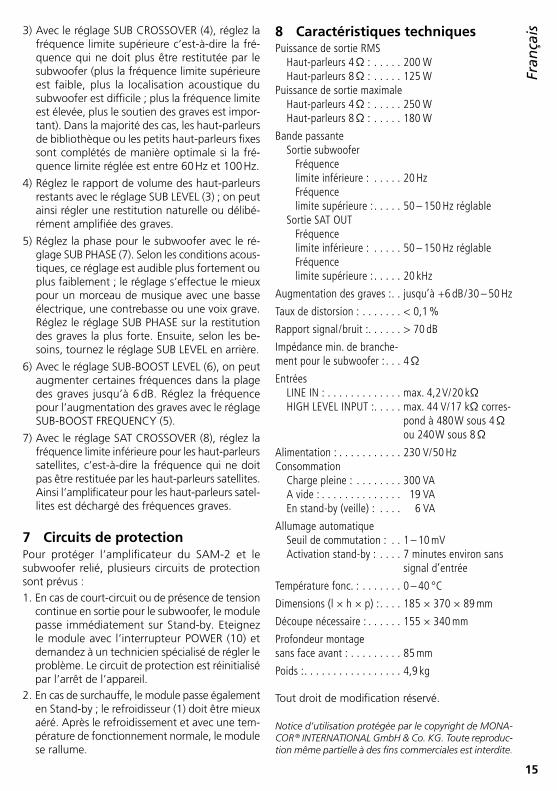
8 Caractéristiques techniquesPuissance de sortie RMS Haut-parleurs 4 Ω : � � � � � 200 W Haut-parleurs 8 Ω : � � � � � 125 WPuissance de sortie maximale Haut-parleurs 4 Ω : � � � � � 250 W Haut-parleurs 8 Ω : � � � � � 180 W
Bande passante Sortie subwoofer Fréquence limite inférieure : � � � � � 20 Hz Fréquence limite supérieure : � � � � � 50 – 150 Hz réglable Sortie SAT OUT Fréquence limite inférieure : � � � � � 50 – 150 Hz réglable Fréquence limite supérieure : � � � � � 20 kHz
Augmentation des graves : � � jusqu’à +6 dB / 30 – 50 Hz
Taux de distorsion : � � � � � � � < 0,1 %
Rapport signal / bruit : � � � � � � > 70 dB
Impédance min� de branche-ment pour le subwoofer : � � � 4 Ω
Entrées LINE IN : � � � � � � � � � � � � � max� 4,2 V/ 20 kΩ HIGH LEVEL INPUT : � � � � � max� 44 V/ 17 kΩ corres-
pond à 480 W sous 4 Ω ou 240 W sous 8 Ω
Alimentation : � � � � � � � � � � � 230 V/ 50 HzConsommation Charge pleine : � � � � � � � � 300 VA A vide : � � � � � � � � � � � � � � 19 VA En stand-by (veille) : � � � � 6 VA
Allumage automatique Seuil de commutation : � � 1 – 10 mV Activation stand-by : � � � � 7 minutes environ sans
signal d’entrée
Température fonc� : � � � � � � � 0 – 40 °C
Dimensions (l × h × p) : � � � � 185 × 370 × 89 mm
Découpe nécessaire : � � � � � � 155 × 340 mm
Profondeur montage sans face avant : � � � � � � � � � 85 mm
Poids : � � � � � � � � � � � � � � � � � 4,9 kg
Tout droit de modification réservé .
Notice d’utilisation protégée par le copyright de MONACOR ® INTERNATIONAL GmbH & Co. KG. Toute reproduction même partielle à des fins commerciales est interdite.

16
ItalianoDeutsch
Deutsch Seite
EnglishEnglish Page
FrançaisFrançais Page
EspañolEspañol Página
NederlandsNederlands Pagina
PolskiPolski Strona
SUBLEVEL
GREEN – ONRED – STAND-BY
SUBCROSSOVER LEVEL
SUBPHASE
SATCROSSOVER
100HzFREQUENCY
40Hz
SUB-BOOST
GROUNDLIFT
POWER
LINE IN SAT OUT230V~ / 50 Hz / 300VA
HIGH LEVEL INPUT
LEFT RIGHT
RIGHT
LEFT
SAM-2 ACTIVE SUBWOOFER MODULE
T3.15AL
MIN MAX 50Hz 150Hz 0 0 180 30Hz 50Hz 50Hz 150Hz
100Hz
GND LIFT
250 W MAX • 200 W RMS / 4 Ω • 125 W RMS / 8 Ω
+ 6dB ° °
14 15
13
9
3 4 5 6 7 8
1
11
10
12
2
Modulo attivo subwooferQueste istruzioni sono rivolte all’utente con cono-scenze base elettroniche . Vi preghiamo di leggerle attentamente prima dell’installazione e di conser-varle per un uso futuro .
1 Panoramica1 Dissipatore di calore; a pieno carico può riscal-
darsi fino a 60 °C Il dissipatore di calore deve poter dissipare il calore senza ostacoli . In caso di surriscalda-mento, il modulo va in stand-by .
2 LED per lo stato di funzionamentorosso = stand-byverde = stadio finale acceso
3 Regolatore SUB LEVEL per impostare il volume
4 Regolatore SUB CROSSOVER per impostare la frequenza superiore di taglio per il subwoofer
5 Regolatore SUB-BOOST FREQUENCY per im-postare la frequenza per l’aumento dei bassi
6 Regolatore SUB-BOOST LEVEL per impostare l’aumento dei bassi fino a +6 dB max .
7 Regolatore SUB PHASE per impostare la fase per il subwoofer
8 Regolatore SAT CROSSOVER per impostare la frequenza inferiore di taglio del passaalto per l’uscita SAT OUT (15)
9 Interruttore GroundliftTasto non premuto Massa del segnale e pannello frontale / con-
duttore di terra sono separati
Tasto premuto Massa del segnale e pannello frontale / con-
duttore di terra sono collegati elettricamente
10 Interruttore on / off POWER
11 Presa di rete per il collegamento con una presa (230 V/ 50 Hz) per mezzo del cavo rete in do-tazione
12 Portafusibili; sostituire un fusibile difettoso sempre con uno dello stesso tipo
13 Prese HIGH LEVEL INPUT per l’ingresso del se-gnale per il collegamento con le uscite per alto-parlanti di un amplificatore finale [in alternativa alle prese RCA LINE IN (14)]
14 Prese RCA LINE IN per un segnale d’ingresso con livello Line [in alternativa alle prese HIGH LEVEL INPUT (13)]
15 Prese RCA SAT OUT, uscita segnale con livello Line per il collegamento con uno stadio finale stereo per gli altoparlanti satelliti
2 Avvertenze di sicurezzaQuest’apparecchio è conforme a tutte le direttive rilevanti dell’UE e pertanto porta la sigla .
AVVERTIMENTO Il modulo funziona con perico-losa tensione di rete . Durante il montaggio in una cassa acustica fare attenzione che il
modulo non venga collegato con la tensione di rete . Staccare la spina di rete dalla presa! Altri-menti si può verificare una scossa pericolosa .
ItalianoItaliano Pagina

17
Italiano• Far funzionare il modulo solo all’interno di lo-
cali . Proteggerlo dall’acqua gocciolante e dagli spruzzi d’acqua, da alta umidità dell’aria e dal calore (temperatura d’impiego ammessa fra 0 e 40 °C) .
• Non depositare sulla cassa acustica dei conteni-tori riempiti di liquidi, p . es . bicchieri .
• Dopo il montaggio del modulo, il calore che si crea dentro la cassa acustica viene dissipata dai dissipatori di calore (1) . Non coprire i dissipatori . Non collocare la cassa direttamente contro una parete, ma mantenere una certa distanza .
• Non mettere in funzione il modulo e staccare subito la spina rete se:1 . il modulo o il cavo rete presentano dei danni
visibili;2 . dopo una caduta o dopo eventi simili sussiste
il sospetto di un difetto;3 . il modulo non funziona correttamente .Per la riparazione rivolgersi sempre ad un’offi-cina competente .
• Staccare il cavo rete afferrando la spina, senza tirare il cavo .
• Per la pulizia usare solo un panno morbido, asciutto; non impiegare in nessun caso prodotti chimici o acqua .
• Nel caso d’uso improprio, do montaggio scor-retto, di collegamenti sbagliati, di impiego scor-retto o di riparazione scorretta non si assume nessuna responsabilità per eventuali danni consequenziali a persone o a cose e cessa ogni diritto di garanzia .
Se si desidera eliminare l’apparecchio definitivamente, consegnarlo per lo smaltimento ad un’istituzione locale per il riciclaggio .
3 Possibilità d’impiegoIl modulo SAM-2 è uno stadio finale di amplifi-catore 200 W, completamente montato, con ali-mentatore, ed è stato realizzato per il montaggio in una cassa acustica a 4 Ω o 8 Ω . Grazie al filtro subwoofer integrato di 18 dB, è possibile creare una cassa subwoofer attiva . Il modulo e l’altoparlante collegato sono protetti da un filtro subsonico di 24 dB e da ampi circuiti di protezione .
Il particolare vantaggio del SAM-2 è il fatto che come subwoofer attivo completamente montato, può essere collocato in qualsiasi punto della sala . Con i regolatori per il livello e per la fase può essere adattato in modo ottimale agli altoparlanti satelliti .
4 MontaggioAVVERTIMENTO Durante il montaggio, il mo-
dulo non dev’essere collegato in nessun caso con la tensione di rete!
1) Per il montaggio del modulo in una cassa acu-stica, preparare un’apertura di 155 × 340 mm . Con il pannello frontale non incassato, la pro-fondità di montaggio è di 85 mm .
2) Si possono collegare solo altoparlanti o sistemi di altoparlanti con un’impedenza globale di 4 Ω minimo . Collegare l’altoparlante mediante connettori piatti con i contatti OUT+ e OUT− a sinistra in alto sulla scheda dello stadio finale (vedi pagina 35), osservando la corretta po-larità: collegare il positivo dell’altoparlante con il contatto OUT+ .
3) Avvitare il modulo nella cassa con dieci viti M4 .
5 Collegare gli apparecchiPrima di effettuare o modificare i collegamenti spegnere il modulo attivo .
5.1 IngressiIl modulo SAM-2 dispone di due ingressi:1 . Le prese RCA LINE IN (14) per segnali con livello
Line per il collegamento p . es . di un preamplifi-catore, mixer, equalizzatore, unità per effetti ecc .
2 . Le prese per apparecchi HIGH LEVEL INPUT (13) per il collegamento con le uscite degli altopar-lanti di un amplificatore finale . Importante: Se si usano le prese per apparec-chi, la potenza d’uscita dell’amplificatore finale collegato non deve superare i 480 W per canale con altoparlanti a 4 Ω, e i 240 W con altoparlanti a 8 Ω, per escludere distorsioni per sovrapilo-taggio .
Il collegamento più sicuro e più semplice è quello con le prese LINE IN (14) . Gli ingressi HIGH LEVEL INPUT (13) si dovrebbero utilizzare solo se non è disponibile nessun segnale Line . Collegare questi ingressi con le uscite per altoparlanti di un ampli-ficatore servendosi di cavi per altoparlanti .
Fare attenzione nel collegare le prese per apparecchi!a . Negli amplificatori finali con potenza d’uscita
superiore a quella indicata sopra, alle prese HIGH LEVEL INPUT è presente una tensione pericolosa per il contatto .
b . In caso di cortocircuito accidentale, l’amplifica-tore finale può subire dei danni .

18
Italiano
SUBLEVEL
GREEN – ONRED – STAND-BY
SUBCROSSOVER LEVEL
SUBPHASE
SATCROSSOVER
100HzFREQUENCY
40Hz
SUB-BOOST
GROUNDLIFT
POWER
LINE IN SAT OUT230V~ / 50 Hz / 300VA
HIGH LEVEL INPUT
LEFT RIGHT
RIGHT
LEFT
SAM-2 ACTIVE SUBWOOFER MODULE
T3.15AL
MIN MAX 50Hz 150Hz 0 0 180 30Hz 50Hz 50Hz 150Hz
100Hz
GND LIFT
250 W MAX • 200 W RMS / 4 Ω • 125 W RMS / 8 Ω
+ 6dB ° °
14 15
13
9
3 4 5 6 7 8
1
11
10
12
2
c . Durante il collegamento, fare attenzione alla cor-retta polarità: collegare il positivo (il conduttore contrassegnato) con il terminale rosso .
5.2 UsciteCollegare le prese RCA SAT OUT (15) con gli in-gressi di uno stadio finale stereo che gestisce gli altoparlanti satelliti .
Negli amplificatori di qualità con uscita pream-plificatore regolata (marcata eventualmente “Pre Out”) e con un ingresso stadio finale (marcato eventualmente “Amp In”), il modulo SAM-2 può essere inserito anche nell’amplificatore: collegare le prese LINE IN (14) con l’uscita preamplificatore e le prese SAT OUT (15) con l’ingresso dello stadio finale .
5.3 AlimentazioneAlla fine inserire il cavo rete in dotazione prima nella presa (11) e quindi in una presa di rete (230 V/ 50 Hz) .
6 FunzionamentoTutte le impostazioni e giudizi sul suono sono pos-sibili solo in collegamento con gli altoparlanti satel-liti . Il suono dovrebbe essere valutato sul posto di ascolto definitivo e una seconda persona dovrebbe effettuare gli adattamenti sul subwoofer attivo seguendo le indicazioni di chi giudica l’ascolto .1) Accendere la cassa attiva con l’interruttore
POWER (10) . Finché non è presente nessun se-gnale d’ingresso, la cassa si trova nella modalità
economica di stand-by e il LED di controllo (2) è rosso . Non appena è presente un segnale, lo stadio finale si accende e il LED diventa verde .
Se per oltre 7 minuti manca il segnale, la cassa attiva ritorna nella modalità di stand-by (LED = rosso) . Se non viene usata per un pe-riodo prolungato, conviene spegnerla con l’in-terruttore POWER perché in stand-by consuma comunque sempre un po’ di corrente .
Se la commutazione automatica fra stand-by e funzionamento non dovesse funzionare in modo ottimale, è possibile modificare la soglia d’inserzione fra 1 e 10 mV . Il regolatore per la soglia d’inserzione si trova in posizione RVa sul circuito integrato del preamplificatore (vedi pagina 35) . Più si gira il regolatore in senso orario, più deve essere alto il livello d’ingresso con il quale il modulo reagisce .
2) Se il collegamento ha provocato un anello di terra si sente un ronzio (p . es . con la musica a basso volume) . Tale anello può essere interrotto con l’interruttore Groundlift (9) . Però, l’amplifi-catore non è protetto contro interferenze elet-triche se il pannello frontale con è collegato con la massa . Nel dubbio si deve provare quale posizione dell’interruttore è la migliore .
3) Impostare la frequenza superiore di taglio con il regolatore SUB CROSSOVER (4), cioè la fre-quenza che non deve più essere riprodotta dal subwoofer (più è bassa la frequenza superiore di taglio, più è difficile localizzare il subwoofer per

19
Italianol’udito; più è alta tale frequenza, più forti sono i
bassi) . Nella maggior parte dei casi, gli altopar-lanti inseriti negli scaffali o i piccoli altoparlanti vengono integrati in modo ottimale se la fre-quenza di taglio è impostata fra 60 Hz e 100 Hz .
4) Impostare il volume rispetto agli altri altoparlanti con il regolatore SUB LEVEL (3) . In questo modo è possibile trovare una riproduzione dei bassi naturale o volutamente forte .
5) Impostare le fasi per il subwoofer con il rego-latore SUB PHASE (7) . Questa impostazione è percepibile più o meno forte a seconda della situazione acustica . L’impostazione è più fa-cile con un brano con basso elettronico, con un contrabbasso o con una voce umana bassa . Impostare il regolatore SUB PHASE sulla ripro-duzione più forte dei bassi, quindi abbassare se necessario il regolatore SUB LEVEL .
6) Con il regolatore SUB-BOOST LEVEL (6) si pos-sono aumentare fino a 6 dB determinate fre-quenze nei bassi . Impostare la frequenza per l’aumento dei bassi con il regolatore SUB-BOOST FREQUENCY (5) .
7) Impostare la frequenza inferiore di taglio per gli altoparlanti satelliti con il regolatore SAT CROSS-OVER (8), ovvero la frequenza che non deve più esser riprodotta dagli altoparlanti satelliti . In questo modo, l’amplificatore per gli altoparlanti satelliti viene liberato delle frequenze basse .
7 Circuiti di protezionePer proteggere lo stadio finale del SAM-2 e del subwoofer collegato, sono presenti diversi circuiti di protezione:1 . Nel caso di un cortocircuito o di sovrapposizione
di tensione continua all’uscita per il subwoofer, il modulo passa subito nella modalità di stand-by . Spegnere il modulo con l’interruttore POWER (10) e fare eliminare il difetto da una persona esperta . Con lo spegnimento, il circuito di pro-tezione viene resettato .
2 . Anche nel caso di surriscaldamento il modulo passa subito nella modalità di stand-by . In que-sto caso occorre ventilare meglio il dissipatore di calore (1) . Dopo il raffreddamento a temperatura normale d’esercizio, il modulo si attiva da solo .
8 Dati tecniciPotenza efficace con altoparlanti 4 Ω: � � � � 200 W con altoparlanti 8 Ω: � � � � 125 WPotenza musicale con altoparlanti 4 Ω: � � � � 250 W con altoparlanti 8 Ω: � � � � 180 W
Gamma di frequenze Uscita subwoofer frequenza inf� di taglio: � 20 Hz frequenza sup� di taglio: 50 – 150 Hz regolabile Uscita SAT OUT frequenza inf� di taglio: � 50 – 150 Hz regolabile frequenza sup� di taglio: 20 kHz
Aumento bassi: � � � � � � � � � � fino a +6 dB / 30 – 50 Hz
Fattore di distorsione: � � � � � < 0,1 %Rapporto S / R: � � � � � � � � � � � > 70 dB
Impedenza min� di collega-mento per il subwoofer: � � � � 4 Ω
Ingressi LINE IN: � � � � � � � � � � � � � � max� 4,2 V/ 20 kΩ HIGH LEVEL INPUT: � � � � � max� 44 V/ 17 kΩ corri-
spondente a 480 W con 4 Ω o 240 W con 8 Ω
Alimentazione: � � � � � � � � � � 230 V/50 Hz
Assorbimento a pieno carico: � � � � � � � � � 300 VA a vuoto: � � � � � � � � � � � � � � 19 VA in stand-by: � � � � � � � � � � � 6 VA
Inserzione automatica Soglia d’inserzione: � � � � � 1 – 10 mV Attivazione stand-by: � � � � dopo 7 minuti ca� senza
segnale d’ingresso
Temperatura d’esercizio:� � � � 0 – 40 °C
Dimensioni (l × h × p):� � � � � 185 × 370 × 89 mm
Apertura nella cassa: � � � � � � 155 × 340 mm
Profondità di montaggiosenza pannello frontale: � � � � 85 mm
Peso: � � � � � � � � � � � � � � � � � � 4,9 kg
Con riserva di modifiche tecniche .
La MONACOR ® INTERNATIONAL GmbH & Co. KG si riserva ogni diritto di elaborazione in qualsiasi forma delle presenti istruzioni per l’uso. La riproduzione – anche parziale – per propri scopi commerciali è vietata.

20
Ned
erlandsDeutsch
Deutsch Seite
EnglishEnglish Page
FrançaisFrançais Page
ItalianoItaliano Pagina
EspañolEspañol Página
PolskiPolski Strona
SUBLEVEL
GREEN – ONRED – STAND-BY
SUBCROSSOVER LEVEL
SUBPHASE
SATCROSSOVER
100HzFREQUENCY
40Hz
SUB-BOOST
GROUNDLIFT
POWER
LINE IN SAT OUT230V~ / 50 Hz / 300VA
HIGH LEVEL INPUT
LEFT RIGHT
RIGHT
LEFT
SAM-2 ACTIVE SUBWOOFER MODULE
T3.15AL
MIN MAX 50Hz 150Hz 0 0 180 30Hz 50Hz 50Hz 150Hz
100Hz
GND LIFT
250 W MAX • 200 W RMS / 4 Ω • 125 W RMS / 8 Ω
+ 6dB ° °
14 15
13
9
3 4 5 6 7 8
1
11
10
12
2
Actieve subwoofermoduleDeze handleiding is bedoeld voor gebruikers met basiskennis van elektronica . Lees de handleiding grondig door, alvorens het apparaat in gebruik te nemen, en bewaar ze voor latere raadpleging .
1 Overzicht1 Koellichaam, kan in bedrijf bij volle belasting
tot 60 °C warm worden Het koellichaam moet ongehinderd warmte kunnen afstralen . Bij oververhitting schakelt de module naar stand-by .
2 LED voor de bedrijfstoestandrood = stand-by (startklaar)groen = eindversterker ingeschakeld
3 Regelaar SUB LEVEL om het volume in te stellen
4 Regelaar SUB CROSSOVER om de bovenste grensfrequentie voor de subwoofer in te stellen
5 Regelaar SUB-BOOST FREQUENCY om de fre-quentie voor de basversterking in te stellen
6 Regelaar SUB-BOOST LEVEL om de basverster-king op maximaal +6 dB in te stellen
7 Regelaar SUB PHASE om de faseverhouding voor de subwoofer in te stellen
8 Regelaar SAT CROSSOVER om de onderste fre-quentiegrens van het hoogdoorlaatfilter in te stellen voor de uitgang SAT OUT (15)
9 MassaschakelaarToets niet ingedrukt Signaalmassa en frontpaneel / aarding zijn
ge scheiden
Toets ingedrukt Signaalmassa en frontpaneel / aarding zijn
elektrisch verbonden10 POWER-schakelaar11 Netjack voor de aansluiting op een stopcontact
(230 V/ 50 Hz) via het meegeleverde netsnoer12 Zekeringhouder;
vervang een gesmolten zekering uitsluitend door een zekering van hetzelfde type
13 Jacks HIGH LEVEL INPUT voor de signaalingang om de eindversterker op de luidsprekeruitgan-gen aan te sluiten [alternatief voor de cinch-jacks LINE IN (14)]
14 Cinch-jacks LINE IN voor een ingangssignaal met lijnniveau [alternatief voor de jacks HIGH LEVEL INPUT (13)]
15 Cinch-jacks SAT OUT, signaaluitgang met lijn- niveau om de satellietluidsprekers aan te sluiten op een stereo-eindversterker
2 VeiligheidsvoorschriftenDe module is in overeenstemming met alle rele-vante EU-Richtlijnen en is daarom gekenmerkt met .
WAARSCHUWING De netspanning van de mo-dule is levensgevaarlijk . Let er bij de inbouw in een luid-sprekerkast in elk geval op,
dat de module niet op de netspanning is aange-sloten . Trek de netstekker uit het stopcontact! Anders loopt u het risico van een levensgevaar-lijke elektrische schok .
NederlandsNederlands Pagina

21
Ned
erlands• De module is enkel geschikt voor gebruik bin-
nenshuis . Vermijd druip- en spatwater, uitzon-derlijk war me plaatsen en plaatsen met een hoge vochtigheid (toegestaan omgevingstem-peratuurbereik: 0 – 40 °C) .
• Plaats geen bekers met vloeistof (bv . drink-glazen) op de luidsprekerkast .
• Na de inbouw van de module wordt de in de luidsprekerkast ontstane warmte via de koelrib-ben (1) afgegeven . Dek ze daarom niet af . Plaats de box niet direct tegen een muur; zorg dat er voldoende afstand tussen de muur en de box is .
• Schakel de module niet in resp . trek onmiddellijk de stekker uit het stopcontact:1 . wanneer de module of het netsnoer zichtbaar
beschadigd zijn,2 . wanneer er een defect zou kunnen optreden
nadat de module bijvoorbeeld gevallen is,3 . wanneer de module slecht functioneert .De module moet in elk geval hersteld worden door een gekwalificeerd vakman .
• Trek de stekker nooit met het snoer uit het stop-contact, maar met de stekker zelf .
• Verwijder het stof met een droge, zachte doek . Gebruik zeker geen water of chemicaliën .
• In geval van ongeoorloofd of verkeerd gebruik, verkeerde montage, foutieve aansluiting resp . bediening of van herstelling door een niet- gekwalificeerd persoon vervalt de garantie en de verantwoordelijkheid voor hieruit resulterende materiële of lichamelijke schade .
Wanneer de module definitief uit bedrijf wordt genomen, bezorg het dan voor milieuvriendelijke verwerking aan een plaatselijk recyclagebedrijf .
3 ToepassingenDe inbouwmodule SAM-2 is een volledig uitgeruste eindversterker van 200 W met voedingseenheid en bedoeld voor inbouw in een luidsprekerkast van 4 Ω of 8 Ω . Door de scheidingsfilter van 18 dB in de subwoofer kunt u een actieve-subwoofer-box creëren . De module en de aangesloten luidspreker worden beveiligd door een subsonisch filter van 24 dB en uitgebreide beveiligingscircuits .
Het bijzondere voordeel van de SAM-2 is dat hij als gebruiksklaar gemonteerde actieve sub-woofer overal in het luisterbereik kan worden opgesteld . Door regelaars voor het niveau en de faseverhouding kunt u hem optimaal op de satel-lietluidsprekers afstemmen .
4 MontageWAARSCHUWING
Tijdens de montage mag de module in geen geval met netspanning zijn verbonden!
1) Om de module te kunnen inbouwen, zaagt u in de luidsprekerkast een uitsparing van 155 × 340 mm . De nodige inbouwdiepte bedraagt 85 mm; de frontplaat is dan niet verzonken .
2) Er mogen uitsluitend luidsprekers resp . luidspre-kersystemen worden aangesloten met een totale impedantie van minstens 4 Ω . Verbind de luid-spreker via platte stekkers met de aansluitingen OUT+ en OUT− links bovenaan de eindversterker (zie pagina 35) . Let daarbij op de correcte polariteit, d .w .z . sluit de positieve pool van de luidspreker aan op het contact OUT+ .
3) Zet de module op de box vast met tien schroe-ven M4 .
5 Toestellen aansluitenSchakel de module uit, alvorens aansluitingen te maken resp . bestaande aansluitingen te wijzigen .
5.1 IngangenDe module SAM-2 heeft twee ingangen ter be-schikking:1 . De cinch-jacks LINE IN (14) voor signalen met
lijnniveau voor de aansluiting van bv . voorver-sterkers, mengpanelen, equalizers, effectenap-paraten etc .
2 . De apparaatjacks HIGH LEVEL INPUT (13) voor de aansluiting van een eindversterker op de luid-sprekeruitgangen . Belangrijk: Bij gebruik van de apparaatjacks (13) mag het uitgangsvermogen van de aangesloten eindversterker niet hoger liggen dan 480 W per kanaal op luidsprekers van 4 Ω resp . 240 W per kanaal op luidsprekers van 8 Ω . Zo niet worden de signalen vervormd door oversturing .
Het eenvoudigste en veiligste is een aansluiting op de jacks LINE IN (14) . Uitsluitend wanneer er geen lijnsig naal beschikbaar is, moet u de ingangen HIGH LEVEL INPUT (13) gebruiken . Verbind deze ingangen via luidsprekerkabels met de luidspreker-uitgangen van een eindversterker .
Let op bij de aansluiting via de apparaatjacks!a . Bij eindversterkers met een hoger uitgangsver-
mogen dan hierboven aangegeven, staan de jacks HIGH LEVEL INPUT onder een levensge-vaarlijke spanning .

22
Ned
erlands
SUBLEVEL
GREEN – ONRED – STAND-BY
SUBCROSSOVER LEVEL
SUBPHASE
SATCROSSOVER
100HzFREQUENCY
40Hz
SUB-BOOST
GROUNDLIFT
POWER
LINE IN SAT OUT230V~ / 50 Hz / 300VA
HIGH LEVEL INPUT
LEFT RIGHT
RIGHT
LEFT
SAM-2 ACTIVE SUBWOOFER MODULE
T3.15AL
MIN MAX 50Hz 150Hz 0 0 180 30Hz 50Hz 50Hz 150Hz
100Hz
GND LIFT
250 W MAX • 200 W RMS / 4 Ω • 125 W RMS / 8 Ω
+ 6dB ° °
14 15
13
9
3 4 5 6 7 8
1
11
10
12
2
b . Bij een per ongeluk veroorzaakte kortsluiting kan de eindversterker worden beschadigd .
c . Let bij de aansluiting op de correcte polariteit: Verbind de positieve pool (gemarkeerde ader van de luidsprekerkabel) telkens met de rode apparaatjack .
5.2 UitgangenVerbind de cinch-jacks SAT OUT (15) met de ingan-gen van een stereo-eindversterker die de satelliet-luidsprekers stuurt .
Bij hoogwaardige, loskoppelbare krachtver-sterkers met een voorversterkeruitgang (mogelijk opschrift “Pre Out”) en een eindversterkeringang (mogelijk opschrift “Amp In”) kan de module SAM-2 ook op de krachtversterker worden aan-gesloten: Sluit de jacks LINE IN (14) aan op de voorversterkeruitgang en de jacks SAT OUT (15) op de eindversterkeringang .
5.3 VoedingsspanningTen slotte verbindt u het meegeleverde netsnoer eerst met de jack (11) en plugt u het in een stop-contact (230 V/ 50 Hz) .
6 BedieningU kunt de instellingen pas controleren, wanneer de verbinding met de satellietluidsprekers tot stand is gebracht . De klank moet op de uiteindelijke luis-terplaats worden beoordeeld en door een tweede persoon op de actieve subwoofer volgens aanwij-zingen optimaal afgeregeld .1) Schakel de actieve box met de POWER-schake-
laar (10) in . Zolang er geen ingangssignaal is,
staat de box in energiesparende bedrijfsmodus (stand-by), en de controle-LED (2) licht rood op . Zodra er een signaal is, schakelt de eindverster-ker in en licht de LED groen op .
Indien er gedurende ca . 7 minuten geen signaal is, schakelt de actieve box terug naar stand-by-modus (LED = rood) . Indien de actieve box gedurende langere tijd niet wordt gebruikt, moet u hem met de POWER-schakelaar uitscha-kelen . Anders is er in de stand-by-modus steeds een klein stroomverbruik .
Als het automatisch omschakelen tussen standbymodus en bedrijfsmodus niet optimaal zou functioneren, kunt u de inschakeldrempel in het bereik van 1 – 10 mV veranderen . De re-gelaar voor de inschakeldrempel bevindt zich in de positie RVa op de printplaat van de voor-versterker (zie pagina 35) . Hoe verder de re-gelaar naar rechts wordt gedraaid, hoe hoger het ingangsniveau moet zijn, waarbij de module inschakelt .
2) Indien de aansluiting een aardlus veroorzaakt, dan is er een bromgeluid hoorbaar (bv . bij zachte muziekfragmenten) . U kunt deze aardlus onder-breken met behulp van een massaschakelaar (9) . Anderzijds is de versterker niet beschermd tegen elektrische storingsvelden, als het front-paneel niet met de massa is verbonden . In geval van twijfel plaatst u de schakelaar afwisselend in beide standen om de optimale instelling te vinden .
3) Stel met de regelaar SUB CROSSOVER (4) de bovenste grensfrequentie in, d .w .z . de fre-

23
Ned
erlandsquentie die niet meer door de subwoofer mag
worden weergegeven (hoe lager de bovenste grensfrequentie, hoe moeilijker de akoestische lokalisering van de subwoofer; hoe hoger de grensfrequentie, hoe sterker de basondersteu-ning) . In de meeste gevallen worden boeken-plankluidsprekers en kleine staan de luidsprekers optimaal aangevuld, wanneer de grensfrequen-tie tussen 60 Hz en 100 Hz is ingesteld .
4) Stel de volumeverhouding met de andere luid-sprekers in met de regelaar SUB LEVEL (3) . Zo kunt u een natuurlijke of een bewust versterkte basweergave instellen .
5) Stel de faseverhouding voor de subwoofer in met de regelaar SUB PHASE (7) . Deze instelling is volgens de akoestische omstandigheden sterker of zwakker waarneembaar . Het best gebeurt de instelling aan de hand van een muziekstuk met een elektronische bas, een contrabas of een diepe basstem . Stel de regelaar SUB PHASE in op de luidste basweergave . Draai de regelaar SUB LEVEL daarna terug indien nodig .
6) Met de regelaar SUB-BOOST LEVEL (6) kunt u bepaalde frequenties in het diepebasbereik met maximum 6 dB versterken . Stel met de regelaar SUB-BOOST FREQUENCY (5) de frequentie in voor de basversterker .
7) Stel met de regelaar SAT CROSSOVER (8) de onderste frequentiegrens voor de satellietluid-sprekers in, d .w .z . de frequentie die niet meer door de satellietluidspreker mag worden weer-gegeven . Op deze manier ontlast u de verster-ker voor de satellietluidsprekers van de lage frequenties .
7 BeveiligingscircuitsVoor de bescherming van de eindversterker van de SAM-2 en de aangesloten subwoofer zijn er verschillende beveiligingscircuits beschikbaar:
1 . Bij een kortsluiting of een gelijkspanning op de uitgang voor de subwoofer schakelt de module onmiddellijk naar stand-by-modus: Schakel de module uit met de POWER-schakelaar (10) en laat de fout door deskundig personeel verhel-pen . Het beveiligingscircuit wordt gereset door de vesterker uit en in te schakelen .
2 . Bij oververhitting schakelt de module eveneens naar stand-by-modus . Zorg voor een betere ventilatie van het koellichaam (1) . Na afkoeling tot de normale bedrijfstemperatuur schakelt de module weer in .
8 Technische gegevensSinusvermogen op luidsprekers van 4 Ω: � � 200 W op luidsprekers van 8 Ω: � � 125 WMuziekvermogen op luidsprekers van 4 Ω: � � 250 W op luidsprekers van 8 Ω: � � 180 W
Frequentiebereik Subwooferuitgang onderste grensfrequentie: � � � � � � 20 Hz bovenste grensfreq�: � � � 50 – 150 Hz instelbaar Uitgang SAT OUT onderste grensfreq�: � � � 50 – 150 Hz instelbaar bovenste grensfreq�: � � � 20 kHz
Versterking van de diepe bastonen: � � � � � � � tot +6 dB / 30 – 50 Hz
THD: � � � � � � � � � � � � � � � � � � < 0,1 %
Signaal / Ruis-verhouding: � � � > 70 dB
min� aansluitimpedantievoor de subwoofer: � � � � � � � 4 Ω
Ingangen LINE IN: � � � � � � � � � � � � � � max� 4,2 V/ 20 kΩ HIGH LEVEL INPUT: � � � � � max� 44 V/ 17 kΩ komt
overeen met 480 W op 4 Ω resp� 240 W op 8 Ω
Voedingsspanning:� � � � � � � � 230 V/ 50 Hz
Vermogens-opname bij volle belasting: � � � � � � 300 VA bij nullast: � � � � � � � � � � � � 19 VA in stand-by-modus: � � � � � 6 VA
Automatische inschakeling Inschakeldrempel: � � � � � � 1 – 10 mV Activering stand-by-modus: na ca� 7 minuten zonder
ingangssignaalOmgevings-temperatuurbereik: � � � � � � � 0 – 40 °C
Afmetingen (B × H × D): � � � 185 × 370 × 89 mm
Vereiste uitsparing in kast: � � 155 × 340 mm
Inbouwdiepte zonder frontpaneel: � � � � � � � 85 mm
Gewicht: � � � � � � � � � � � � � � � 4,9 kg
Wijzigingen voorbehouden .
Deze gebruiksaanwijzing is door de auteurswet beschermd eigendom van MONACOR ® INTERNATIONAL GmbH & Co. KG. Een reproductie – ook gedeeltelijk – voor eigen commerciële doeleinden is verboden.

24
Españ
olDeutsch
Deutsch Seite
EnglishEnglish Page
FrançaisFrançais Page
ItalianoItaliano Pagina
NederlandsNederlands Pagina
PolskiPolski Strona
SUBLEVEL
GREEN – ONRED – STAND-BY
SUBCROSSOVER LEVEL
SUBPHASE
SATCROSSOVER
100HzFREQUENCY
40Hz
SUB-BOOST
GROUNDLIFT
POWER
LINE IN SAT OUT230V~ / 50 Hz / 300VA
HIGH LEVEL INPUT
LEFT RIGHT
RIGHT
LEFT
SAM-2 ACTIVE SUBWOOFER MODULE
T3.15AL
MIN MAX 50Hz 150Hz 0 0 180 30Hz 50Hz 50Hz 150Hz
100Hz
GND LIFT
250 W MAX • 200 W RMS / 4 Ω • 125 W RMS / 8 Ω
+ 6dB ° °
14 15
13
9
3 4 5 6 7 8
1
11
10
12
2
Módulo Subwoofer ActivoEstas instrucciones van dirigidas a usuarios con conocimientos básicos de electrónica . Por favor lea estas instrucciones atentamente antes de la instalación y guárdelas para usos posteriores .
1 Vista General1 Disipador; puede calentarse durante el funcio-
namiento bajo carga plena hasta 60 °C Hay que permitir que el calor circule por todas las rejillas de ventilación . En caso de sobrecalen-tamiento, el módulo se conmuta en stand-by .
2 LED para indicar el modo de funcionamientorojo = stand-byverde = amplificador conectado
3 Control SUB LEVEL para ajustar el volumen
4 Control SUB CROSSOVER para ajustar la fre-cuencia de corte superior para el subwoofer
5 Control SUB-BOOST FREQUENCY para ajustar la frecuencia para el aumento de los graves
6 Control SUB-BOOST LEVEL para ajustar el aumento de los graves hasta +6 dB máx .
7 Control SUB PHASE para ajustar la fase para el subwoofer
8 Control SAT CROSSOVER para ajustar la fre-cuencia de corte inferior del pasa alto para la salida SAT OUT (15)
9 Interruptor Groundliftbotón no pulsado la masa de la señal y la parte delantera /
conductor protector están separadas
botón pulsado la masa de la señal y la parte delantera /
conductor protector están conectadas eléc-tricamente
10 Interruptor POWER11 Toma de red para conectar el módulo vía el
cable de conexión entregado a un enchufe (230 V/ 50 Hz)
12 Soporte de fusible; siempre cambie un fusible dañado por un fusible del mismo tipo
13 Tomas HIGH LEVEL INPUT para la entrada de señal para la conexión a las salidas de altavoz de un amplificador; alternativa con las tomas RCA LINE IN (14)
14 Tomas RCA LINE IN para una señal de entrada con nivel de línea; alternativa con las tomas HIGH LEVEL INPUT (13)
15 Tomas RCA SAT OUT, salida de señal con nivel de línea para la conexión a un amplificador estéreo para los altavoces de satélite
2 Notas de SeguridadEl módulo cumple con todas las directivas rele-vantes de la UE y por lo tanto está marcado con el símbolo .
ADVERTENCIA El módulo utiliza un voltaje peli-groso . Durante la instalación en un recinto, asegúrese de que el módulo no está conectado con el voltaje de red . Desconecte el cable
de red; de otro modo podría sufrir una descarga eléctrica mortal .
EspañolEspañol Página

25
Españ
ol• El módulo está adecuado sólo para utilizarse en
interiores . Protéjalo de goteos y salipicaduras, elevada humedad del aire y calor (temperatura de ambiente admisible: 0 – 40 °C) .
• No coloque ningún recipiente lleno de líquido encima del recinto, como por ejemplo un vaso .
• Una vez el módulo instalado, el calor generado en el recinto se evacua por las rejillas de venti-lación (1) . No cubra nunca las rejillas de ventila-ción . No instale el recinto directamente contra un muro; conserve una distancia de seguridad .
• No utilice el módulo y desconecte inmediata-mente la toma de corriente del enchufe si:1 . el módulo o en el cable de conexión están
visiblemente dañados2 . el módulo ha sufrido daños después de una
caída o accidente similar3 . no funciona correctamenteSólo el personal técnico puede reparar el módulo bajo cualquier circunstancia .
• No tire nunca del cable de red para desconec-tarlo de la toma; tire siempre del enchufe .
• Para limpiar el módulo, utilice un trapo seco y suave; no utilice nunca ni productos químicos ni agua .
• No podrá reclamarse garantía o responsabilidad alguna por cualquier daño personal o material resultante si el módulo se utiliza para otros fines diferentes a los originalmente concebidos, si no se instala, conecta o utiliza adecuadamente o si no se repara por expertos .
Si va a poner el módulo fuera de servicio definitivamente, llévelo a la planta de reci-claje más cercana para que su eliminación no sea perjudicial para el medioambiente .
3 AplicacionesEl módulo de inserción SAM-2 es un amplificador de 200 W completo con alimentador y diseñado para instalarse en un recinto de 4 Ω o 8 Ω . Gra-cias al filtro subwoofer 18 dB integrado es posible realizar un recinto activo subwoofer . El módulo y el altavoz conectado están protegidos por un filtro subsónico 24 dB y numerosos circuitos de protección .
La ventaja especial del SAM-2 es su facultad de colocarse en cualquier lugar de la sala de escu-cha como subwoofer activo ya montado . Con los controles del nivel y de la fase, puede adaptarse de manera óptima a los altavoces de satélite .
4 MontajeADVERTENCIA
¡Durante el montaje, el módulo no debe conectarse en ningún caso con la alimentación de red!
1) Para el montaje del módulo en el recinto, haga un corte de 155 × 340 mm; la profundidad de montaje necesaria es de 85 mm si la parte de-lantera no está encastrada .
2) Sólo altavoces o sistemas de altavoz de una impedancia total de 4 Ω como mínimo se pue-den conectar . Conecte el altavoz vía conecto-res planos con los contactos OUT+ y OUT− a la izquierda arriba de la platina del amplificador (ver página 35) . Observe la polaridad correcta, es decir, conecte el polo positivo del altavoz al contacto OUT+ .
3) Utilice 10 tornillos M4 para atornillar el módulo al recinto .
5 Conexión de los AparatosAntes de efectuar las conexiones o de modificar las conexiones existentes, desconecte el recinto activo .
5.1 EntradasEl módulo SAM-2 dispone de dos entradas:
1 . Las tomas RCA LINE IN (14) para las señales con nivel de línea para conectar por ejemplo preamplificador, mezclador, ecualizador, aparato de efectos etc .
2 . Las tomas HIGH LEVEL INPUT (13) para la cone-xión a las salidas de altavoz de un amplificador . Importante: Si las tomas HIGH LEVEL INPUT se utilizan, la potencia de salida del amplificador conectado no debe sobrepasar los 480 W por canal para los altavoces de 4 Ω o 240 W por canal para los altavoces de 8 Ω; de otro modo, la sobrecarga puede generar distorsiones de señal .
Lo más sencillo y lo más seguro es la conexión a las tomas LINE IN (14) . Las entradas HIGH LEVEL INPUT (13) deberían utilizarse sólo si la señal de línea no está disponible . Conecte estas entradas vía cables de altavoz con las salidas de altavoz de un amplificador .
¡Atención durante la conexión mediante la tomas HIGH LEVEL INPUT!a . En amplificadores con una potencia de salida
más elevada que la citada anteriormente, hay peligro de contacto con un voltaje peligroso en las tomas HIGH LEVEL INPUT .

26
Españ
ol
SUBLEVEL
GREEN – ONRED – STAND-BY
SUBCROSSOVER LEVEL
SUBPHASE
SATCROSSOVER
100HzFREQUENCY
40Hz
SUB-BOOST
GROUNDLIFT
POWER
LINE IN SAT OUT230V~ / 50 Hz / 300VA
HIGH LEVEL INPUT
LEFT RIGHT
RIGHT
LEFT
SAM-2 ACTIVE SUBWOOFER MODULE
T3.15AL
MIN MAX 50Hz 150Hz 0 0 180 30Hz 50Hz 50Hz 150Hz
100Hz
GND LIFT
250 W MAX • 200 W RMS / 4 Ω • 125 W RMS / 8 Ω
+ 6dB ° °
14 15
13
9
3 4 5 6 7 8
1
11
10
12
2
b . En caso de cortocircuito accidental, el amplifi-cador puede dañarse .
c . Durante la conexión, observe la polaridad correcta: Conecte el polo positivo (conductor del cable de altavoz marcado) con la toma roja .
5.2 SalidasConecte las tomas RCA SAT OUT (15) con las entra-das de un amplificador estéreo que hace funcionar los altavoces de satélite .
Para los amplificadores integrados separables de calidad superior equipados con una salida de preamplificador controlado (inscripción posible “Pre Out”) y una entrada de amplificador (inscrip-ción posible “Amp In”), el módulo SAM-2 puede insertarse también en el amplificador: conecte las tomas LINE IN (14) con la salida del preamplifica-dor y las salidas SAT OUT (14) con la entrada del amplificador .
5.3 AlimentaciónFinalmente conecte el cable entregado a la toma de alimentación (11) y después la otra extremidad a una toma (230 V/ 50 Hz) .
6 FuncionamientoEl conjunto de ajustes y evaluaciones de tonalidad sólo pueden efectuarse en combinación con los altavoces de satélite . Conviene evaluar la tonalidad en el lugar definitivo de escucha y adaptarla mediante una segunda persona que, en el subwoofer activo, efectúa el ajuste óptimo según instrucción .
1) Utilice el interruptor POWER (10) para conec-tar el recinto activo . Mientras ninguna señal de entrada esté disponible, el recinto está en modo espera (stand-by), economisador de corriente, y el LED (2) es rojo . Cuando una señal esté dis-ponible, el amplificador se conecta y el LED se pone entonces de color verde .
Si ninguna señal está disponible, el recinto activo se repone en modo stand-by (LED = rojo) después de 7 minutos aprox . Si el recinto activo no se utiliza durante algún tiempo, debería des-conectarlo con el interruptor POWER; de otro modo, una corriente baja se consume en el modo stand-by .
Si el cambio automático entre stand-by y funcionamiento no actúa correctamente, puede modificarse el umbral de conexión en el rango de 1 – 10 mV . El control para el umbral de cone-xión es en la posición RVa del PCB del preampli-ficador (ver página 35) . Cuanto más se gira el control en el sentido horario, mayor será el nivel de entrada requerido para que se conecte el módulo .
2) Si un bucle de masa aparece por la conexión, un zumbido se produce (p . ej . durante pasajes de música de bajo volumen) . Este bucle de masa puede interrumpirse por el interruptor Ground-lift (9) . Por otra parte, el amplificador no está protegido en contra las interferencias eléctricas si la parte delantera no está conectada con la masa . En caso de duda, ponga el interruptor alternativamente en ambas posiciones para en-contrar el ajuste óptimo .

27
Españ
ol3) Utilice el control SUB CROSSOVER (4) para ajus-
tar la frecuencia de corte superior, es decir, la frecuencia que ya no debe reproducirse por el subwoofer (más baja es la frecuencia de corte superior, más difícil será la localización acústica del subwoofer; más elevada es la frecuencia de corte, más fuerte será el soporte de los gra-ves) . En la mayoría de los casos, los altavoces de estantería y los pequeños altavoces de pie se complementan de manera óptima si la frecuen-cia de corte ajustada está entre 60 Hz y 100 Hz .
4) Utilice el control SUB LEVEL (3) para ajustar la relación de volumen a los altavoces restantes; puede así ajustar una reproducción natural o conscientemente aumentar los graves .
5) Utilice el control SUB PHASE (7) para ajustar la fase para el subwoofer . Este ajuste es percepti-ble más o menos fuerte según las condiciones acústicas; el ajuste se efectúa mejor para una canción con un bajo eléctrico, un contrabajo o una voz de bajo . Ajuste el control SUB PHASE en la reproducción más fuerte de grave . Después, según las necesidades, gire el control SUB LEVEL un poco atrás .
6) Utilice el control SUB-BOOST LEVEL (6) para au-mentar ciertas frecuencias en el rango de los graves hasta 6 dB . Utilice el control SUB-BOOST FREQUENCY (5) para ajustar la frecuencia para el aumento de los graves .
7) Utilice el control SAT CROSSOVER (8) para ajus-tar la frecuencia de corte inferior para los altavo-ces de satélite, es decir, la frecuencia que ya no debe reproducirse por los altavoces de satélite . Así el amplificador para los altavoces de satélite está descargado de las frecuencias graves .
7 Circuitos de ProtecciónPara proteger el amplificador del SAM-2 y el subwoofer conectado, varios circuitos de protec-ción están disponibles:1 . En caso de cortocircuito o de presencia de ten-
sión continua en la salida para el subwoofer, el módulo pasa inmediatamente en stand-by . Apa-gue el módulo con el interruptor POWER (10) y acuda a un técnico especializado de solucionar el problema . El circuito de protección se reinicia por la desconexión del módulo .
2 . En caso de sobrecalentamiento, el módulo pasa también en stand-by . Mejore la ventilación del disipador (1) . Después del enfriamiento a la tem-peratura de funcionamiento normal, el módulo vuelve a conectarse .
8 EspecificacionesPotencia de salida RMS Altavoces 4 Ω: � � � � � � � � � 200 W Altavoces 8 Ω: � � � � � � � � � 125 W
Potencia de salida máxima Altavoces 4 Ω: � � � � � � � � � 250 W Altavoces 8 Ω: � � � � � � � � � 180 W
Rango de frecuencias Salida subwoofer Frecuencia de corte inferior: � � � � � 20 Hz Frecuencia de corte superior: � � � � � 50 – 150 Hz ajustable Salida SAT OUT Frecuencia de corte inferior: � � � � � � 50 – 150 Hz ajustable Frecuencia de corte superior: � � � � � 20 kHz
Aumento de los graves: � � � � hasta +6 dB / 30 – 50 Hz
THD: � � � � � � � � � � � � � � � � � < 0,1 %
Relación señal / ruido: � � � � � � > 70 dB
Impedancia mínima de conexión para el subwoofer: � 4 Ω
Entradas LINE IN: � � � � � � � � � � � � � � máx� 4,2 V/ 20 kΩ HIGH LEVEL INPUT: � � � � � máx� 44 V/ 17 kΩ corres-
ponde a 480 W a 4 Ω o 240 W a 8 Ω
Alimentación: � � � � � � � � � � � 230 V/ 50 Hz
Consumo Carga plena: � � � � � � � � � � 300 VA Sin carga: � � � � � � � � � � � � 19 VA En stand-by (espera): � � � � 6 VA
Conexión automática Umbral de conexión: � � � � 1 – 10 mV Activación stand-by: � � � � 7 minutos aprox� sin
señal de entrada
Temperatura func�: � � � � � � � � 0 – 40 °C
Dimensiones (B × H × P): � � � 185 × 370 × 89 mm
Corte necesario: � � � � � � � � � 155 × 340 mm
Profundidad montaje sin parte delantera: � � � � � � � 85 mm
Peso: � � � � � � � � � � � � � � � � � � 4,9 kg
Sujeto a modificaciones técnicas .
Manual de instrucciones protegido por el copyright de MONACOR ® INTERNATIONAL GmbH & Co. KG. Toda reproducción mismo parcial para fines comerciales está prohibida.

28
PolskiDeutsch
Deutsch Seite
EnglishEnglish Page
FrançaisFrançais Page
ItalianoItaliano Pagina
EspañolEspañol Página
NederlandsNederlands Pagina
SUBLEVEL
GREEN – ONRED – STAND-BY
SUBCROSSOVER LEVEL
SUBPHASE
SATCROSSOVER
100HzFREQUENCY
40Hz
SUB-BOOST
GROUNDLIFT
POWER
LINE IN SAT OUT230V~ / 50 Hz / 300VA
HIGH LEVEL INPUT
LEFT RIGHT
RIGHT
LEFT
SAM-2 ACTIVE SUBWOOFER MODULE
T3.15AL
MIN MAX 50Hz 150Hz 0 0 180 30Hz 50Hz 50Hz 150Hz
100Hz
GND LIFT
250 W MAX • 200 W RMS / 4 Ω • 125 W RMS / 8 Ω
+ 6dB ° °
14 15
13
9
3 4 5 6 7 8
1
11
10
12
2
Aktywny moduł subwooferaNiniejsza instrukcja przeznaczona jest dla użyt-kowników posiadających co najmniej podstawową wiedzę techniczną . Przed rozpoczęciem użytkowa-nia proszę zapoznać się z instrukcją, a następnie zachować ją do wglądu .
1 Elementy sterujące i połączenia1 Radiator . Przy pełnym obciążeniu rozgrzewa się
do 60 °C . Należy zapewnić warunki swobodnego odpro-wadzania ciepła przez radiator . W razie prze-grzania urządzenie przełączy się automatycznie w tryb czuwania
2 Wskaźnik trybu pracyczerwony = czuwaniezielony = wzmac niacz jest włączony
3 Regulator SUB LEVEL do regulacji głośności
4 Regulator SUB CROSSOVER do regulacji górnej granicy częstotliwości filtra dolnoprzepusto-wego subwoofera
5 Regulator SUB-BOOST FREQUENCY do regulacji częstotliwości podbicia basów
6 Regulator SUB-BOOST LEVEL do regulacji pod-bicia basów maksymalnie do +6 dB
7 Regulator SUB PHASE do regulacji fazy sub-woofera
8 Regulator SAT CROSSOVER do regulacji dolnej granicy zwrotnicy górnoprzepustowej wyjścia SAT OUT (15)
9 Wyłącznik uziemieniawyłącznik nie wciśnięty przewód masy i przewód uziemiający kabla
zasilającego są odłączonewyłącznik wciśnięty przewód masy i przewód uziemiający kabla
zasilającego są podłączone
10 Włącznik zasilania
11 Gniazdo zasilania do podłączenia do sieci (230 V/50 Hz)
12 Gniazdo bezpiecznika; bezpiecznik wymieniać zawsze na bezpiecznik tego samego typu
13 Gniazdo HIGH LEVEL INPUT do podłączania sygnału z wyjścia głośnikowego [alternatywne wejście do wejścia sygnału linowego (14)]
14 Gniazdo LINE IN do podłączenia sygnału linio-wego [alternatywne wejście do wejścia HIGH LEVEL INPUT(13)]
15 Gniazda SAT OUT, wyjście sygnału liniowego do podłączenia podwójnej końcówki mocy zasilającej satelity
2 Noty bezpieczeństwaUrządzenie spełnia wszystkie wymagania norm UE dzięki czemu jest oznaczone symbolem .
UWAGA Urządzenie jest zasilane niebezpiecz-nym napięciem sieciowym . Nie wolno podłączać urządzenia do sieci w trak-cie instalacji . Należy odłączyć wtyczkę z gniazda zasilania . W przeciwnym
PolskiPolski Strona

29
Polskiwypadku istnieje ryzyko porażenia prądem elek-
trycznym, które może być bardzo niebezpieczne dla zdrowia .
• Urządzenie przeznaczone jest do użytku tylko wewnątrz pomieszczeń . Należy chronić je przed zalaniem, wilgocią oraz wysoką temperaturą (dopuszczalna temperatura otoczenia pracy to 0 – 40 °C) .
• Nie wolno stawiać na urządzeniu żadnych naczyń wypełnionych cieczami, np .: szklanek z napojami .
• Po zainstalowaniu urządzenia ciepło odpro-wadzane jest poprzez żebra radiatora (1) . W związku z tym nie mogą być one niczym za-słonięte . Nigdy nie należy stawiać urządzenia bezpośrednio przy ścianie . Należy zachować odpowiednią do celów chłodzenia przestrzeń .
• Nie wolno używać oraz należy natychmiast odłą-czyć urządzenie od zasilania:1 . jeżeli widoczne są jakiekolwiek uszkodzenia
urządzenia lub kabla zasilającego,2 . jeżeli urządzenie upadło lub uległo podob-
nemu wypadkowi, który mógł spowodować jego uszkodzenie,
3 . jeżeli występują nieprawidłowości w działaniu urządzenia .
W każdym z powyższych przypadków urządze-nie musi zostać poddane naprawie przez odpo-wiednio wyszkolony personel .
• Nie wolno odłączać urządzenia z gniazda siecio-wego ciągnąć za kabel zasilający, należy zawsze chwytać za wtyczkę .
• Do czyszczenia urządzenia zawsze używać czy-stego i suchego kawałka materiału; nigdy nie należy używać wody, ani środków chemicznych .
• Dostawca oraz producent nie ponoszą odpo-wiedzialności za ewentualnie wynikłe szkody materialne lub uszczerbki na zdrowiu, jeśli urzą-dzenie było używane niezgodnie z przeznacze-niem, zostało niepoprawnie zainstalowane lub obsługiwane oraz było poddawane naprawom przez nieautoryzowany personel .
Po całkowitym zakończeniu eksploatacji, należy oddać urządzenie do punktu re-cyklingu, aby nie zaśmiecać środowiska .
3 ZastosowanieModuł SAM-2 jest kompletnym 200 W wzmacnia-czem ze zintegrowanym zasilaczem przeznaczo-nym do instalacji w obudowach głośnikowych o impedancji 4 Ω i 8 Ω . Moduł wzmacniacza dzięki
wbudowanej aktywnej zwrotnicy trzeciego rzędu (18 dB) nadaje się do zastosowania w aktywnych głośnikach basowych . Urządzenie oraz podłączone do niego głośniki zabezpieczone są poprzez filter infradźwięków 24 dB oraz kompletny system za-bezpieczenia obwodu elektrycznego .
Szczególną cech urządzenia jest to, że może być ono umieszczone w dowolnym miejscu po-mieszczenia jako kompletny aktywny subwoofer . Regulacja poziomu sygnału i regulacja fazy subwo-ofera pozwala na optymalne dostrojenie urządze-nia do pracy satelit .
4 InstalacjaUWAGA
Podczas montażu należy bez-względnie odłączyć kabel zasilający od gniazdka sieciowego!
1) W celu instalacji modułu w obudowie głośnika należy wyciąć otwór o wymiarach 155 mm × 340 mm . Jeżeli przedni panel modułu ma nie odstawać poza obręb obudowy, wymagana głębokość montażowa otworu musi wynosić minimum 85 mm .
2) Podłączać jedynie głośniki lub głośniki połą-czone w obwody o impedancji nie mniejszej niż 4 Ω . W celu podłączenia głośników do mo-dułu wzmacniacza należy użyć terminali wcisko-wych OUT+ i OUT− znajdujących się w górnym, prawym rogu obwodu elektrycznego modułu (patrz strona 35) . Należy zwrócić uwagę na prawidłową polaryzację .
3) Należy użyć dziesięciu śrub typu M4 do przykręce-nia modułu wzmacniacza do obudowy głośnika .
5 PodłączaniePrzed dokonywaniem jakichkolwiek zmian w podłączeniu modułu wzmacniacza należy go bez-względnie wyłączyć .
5.1 WejściaUrządzenie jest wyposażone w dwa wejścia:1 . Wejście liniowe LINE IN (14) do podłączania
sygnału liniowego (z miksera, przedwzmacnia-cza, korektora, etc .)
2 . Wejście HIGH LEVEL INPUT (13) do podłączania głośnikowego sygnału wyjściowego wzmacnia-cza . Uwaga: W przypadku podłączania sygnału do wejść HIGH LEVEL INPUT (13) maksymalna moc wyjściowa podłączonego wzmacniacza nie może przekraczać 480 W na każdym wejściu przy

30
Polski
SUBLEVEL
GREEN – ONRED – STAND-BY
SUBCROSSOVER LEVEL
SUBPHASE
SATCROSSOVER
100HzFREQUENCY
40Hz
SUB-BOOST
GROUNDLIFT
POWER
LINE IN SAT OUT230V~ / 50 Hz / 300VA
HIGH LEVEL INPUT
LEFT RIGHT
RIGHT
LEFT
SAM-2 ACTIVE SUBWOOFER MODULE
T3.15AL
MIN MAX 50Hz 150Hz 0 0 180 30Hz 50Hz 50Hz 150Hz
100Hz
GND LIFT
250 W MAX • 200 W RMS / 4 Ω • 125 W RMS / 8 Ω
+ 6dB ° °
14 15
13
9
3 4 5 6 7 8
1
11
10
12
2
impedancji 4 Ω lub 240 W przy impedancji 8 Ω . W przeciwnym wypadku mogą wystąpić znie-kształcenia spowodowane przesterowaniem .
Podłączanie sygnału wejściowego do gniazda LINE IN (14) jest najprostszym i najbezpieczniej-szym rozwiązaniem . Gniazda HIGH LEVEL INPUT (13) powinny być używane wyłącznie, jeżeli nie ma możliwości podłączenia sygnału liniowego źródła . W celu podłączenia tych gniazd do wyjść głośniko-wych wzmacniacza należy użyć kabli głośnikowych .Przy podłączaniu sygnału głośnikowego do gniazda HIGH LEVEL INPUT (13) należy zacho-wać szczególną ostrożność!a . W przypadku podłączania sygnału głośnikowego
wzmacniacza dużej mocy istnieje niebezpieczeń-stwo, że sygnał podany na wejście HIGH LEVEL INPUT będzie większy niż podany powyżej .
b . W przypadku wystąpienia spięcia może dojść do uszkodzenia końcówki mocy podającej sygnał wejściowy .
c . Należy zwrócić baczną uwagą na prawidłową polaryzację podczas podłączania: żyłę sygnałową (żyłę kabla mikrofonowego z oznaczeniem) na-leży podłączyć do czerwonego zacisku mocują-cego wejścia HIGH INPUT LEVEL .
5.2 WyjściaGniazda wyjściowe urządzenia SAT OUT (15) należy podłączyć do podwójnej końcówki mocy zasilającej satelity .
W przypadku podłączania urządzenia do wzmacniaczy z wyjściem kontroli przedwzmac-niacza (zazwyczaj oznaczonym jako “Pre Out”) oraz wejściem wzmacniacza (Amp In), możliwa jest instalacja urządzenia SAM-2 wewnątrz wzmac-niacza: Należy podłączyć gniazdo LINE IN (14) do wyjścia przedwzmacniacza, a gniazdo SAT OUT (15) do wyjścia wzmacniacza .
5.3 ZasilanieNa końcu należy podłączyć urządzenie do zasila-nia za pomocą załączonego przewodu . Najpierw należy podłączyć końcówką do gniazda zasilają-cego (11), a następnie wtyczkę do gniazda siecio-wego (230 V/ 50 Hz) .

31
Polski6 Działanie
Jakiekolwiek regulacje i ocena dźwięku mogą być dokonywane jedynie po podłączeniu satelit . Ocena dźwięku powinna być dokonywana w najodleglej-szym punkcie odsłuchu . Osoba pozostająca przy subwooferze powinna ustawiać regulatory zgodnie ze wskazówkami osoby oceniającej .
1) Należy włączyć system aktywny za pomocą włącznika zasilania POWER (10) . Dopóki nie jest włączony sygnał wejściowy, urządzenie pozo-staje w energooszczędnym trybie czuwania, a wskaźnik trybu pracy (2) świeci się w kolorze czerwonym . Po włączeniu sygnału wejściowego, urządzenie włącza się, a wskaźnik trybu pracy zapala się na zielono .
Jeżeli sygnał wejściowy nie jest włączany przez okres dłuższy niż około 7 minut, urządze-nie samoczynnie przełącza się w tryb czuwa-nia . Jeżeli urządzenie nie jest wykorzystywane przez dłuższy czas zaleca się wyłączenie go za pomocą włącznika zasilania POWER (10), ponie-waż nawet podczas trybu czuwania w sposób znacznie ograniczony, aczkolwiek następuje zużycie energii .
Jeżeli automatyczne przełączanie między try-bem czuwania a trybem pracy nie funkcjonuje optymalnie, zaleca się zmianę progu działania w zakresie 1 – 10 mV . Regulator progu działania znajduje się w pozycji RVa na płytce PCB przed-wzmacniacza (patrz strona 35) . Im bardziej regulator jest odkręcony zgodnie z ruchem wskazówek zegara, tym wyższy poziom wej-ściowy jest wymagany do włączenia modułu .
2) Jeżeli pozostaje włączona pętla masy, mogą wy-stępować zakłócenia (np .: w postaci buczenia o niskiej częstotliwości) . Pętla masy może zostać odłączona poprzez wyłącznik uziemienia (9) . Jednak w tym przypadku urządzenie nie jest ekranowane przeciwko zakłóceniom spowodo-wanym polem elektromagnetycznym . W przy-padku niepewności wyboru rozwiązania należy naprzemiennie włączając i wyłączając wyłącz-nik uziemienia dokonać wyboru optymalnego ustawienia .
3) W celu regulacji górnej granicy filtra dolnoprze-pustowego subwoofera należy użyć regulatora SUB CROSSOVER (4) . Im niższa jest granica odcięcia częstotliwości, tym trudniejsze jest fi-zyczne zlokalizowanie subwoofera . Im granica
jest wyższa tym mocniejszy jest efekt podbi-cia basów . W większości przypadków głośniki basowe zachowują się najlepiej w przedziale częstotliwości 60 Hz – 100 Hz .
4) Regulacji poziomu głośności w stosunku do po-zostałych urządzeń należy dokonać za pomocą regulatora SUB LEVEL (3) . W ten sposób można ustawić zarówno naturalną, jak i dowolnie zmie-nioną reprodukcję basów .
5) Fazowość subwoofera ustawia się za pomocą re-gulatora SUB PHASE (7) . W zależności od warun-ków akustycznych pomieszczenia, ta regulacja może być bardziej lub mnie słyszalna . Najlepiej jest dokonywać regulacji fazowości odsłuchując nagranie, w którym występuje elektryczny bas, kontrabas lub wokal o bardzo niskim brzmieniu . Należy ustawić regulator SUB PHASE w pozycji, w której będą odtwarzane najgłośniejsze basy . Następnie należy delikatnie zmniejszać regulację SUB LEVEL jeżeli zachodzi taka potrzeba .
6) Należy użyć regulatora SUB-BOOST LEVEL (6) w celu podbicia basów o 6 dB . Częstotliwość podbijanego basu należy ustawić za pomocą regulatora SUB-BOOST FREQUENCY (5) .
7) Regulacji dolnej granicy częstotliwości satelit dokonuje się za pomocą regulatora SAT CROSS- OVER (8) . W ten sposób końcówki mocy zasila-jące satelity nie będą musiały wzmacniać niskich dźwięków o niskiej częstotliwości .
7 Obwody zabezpieczająceW celu zabezpieczenia końcówki mocy urządzenia SAM-2 oraz podłączonych głośników, zastosowano zróżnicowane obwody zabezpieczające .1 . W przypadku spięcia lub podłączenia prądu
elektrycznego do wyjść subwoofera, urządze-nie natychmiast przełączy się w tryb czuwania . Należy wtedy wyłączyć urządzenia za pomocą włącznika zasilania POWER (10) i zwrócić się do wykwalifikowanego specjalisty celem usunięcia problemu . Wyłączenie urządzenia spowoduje restart obwodu zabezpieczającego .
2 . W przypadku przegrzania się urządzenia, rów-nież przełączy się ono w tryb czuwania . Należy wtenczas poprawić wentylację radiatora (1) . Po ochłodzeniu do dopuszczalnej temperatury pracy, urządzenie samoczynnie włączy się po-wrotem w tryb pracy .

32
Polski 8 Dane techniczne
RMS moc wyjściowa przy głośniku 4 Ω: � � � � � � 200 W przy głośniku 8 Ω: � � � � � � 125 WMuzyczna moc wyjściowa przy głośniku 4 Ω: � � � � � � 250 W przy głośniku 8 Ω: � � � � � � 180 WZakres częstotliwości wyjście subwoofera dolna granica częstotliwości: � � � � � � � 20 Hz górna granica częstotliwości: � � � � � � � 50 – 150 Hz
(regulowana) wyjście SAT OUT dolna granic częstotliwości: � � � � 50 – 150 Hz
(regulowana) górna granica częstotliwości: � � � � � � � 20 kHz
Podbicie basów: � � � � � � � � � � do +6 dB / 30 – 50 Hz
THD: � � � � � � � � � � � � � � � � � � < 0,1 %
Współczynnik S / N: � � � � � � � � > 70 dB
Min� impedancja wejścia subwoofera: � � � � � � 4 Ω
Wejścia LINE IN: � � � � � � � � � � � � � � max� 4,2 V/ 20 kΩ HIGH LEVEL INPUT: � � � � � max� 44 V/ 17 kΩ co odpowiada 480 W
przy 4 Ω lub 240 W przy 8 Ω
Zasilanie: � � � � � � � � � � � � � � � 230 V/ 50 Hz
Zużycie energii przy maksymalnym wzmocnieniu: � � � � � � � � � 300 VA bez wzmocnienia: � � � � � � 19 VA w trybie czuwania: � � � � � � 6 VA
Automatyczne włączanie Próg działania: � � � � � � � � � 1 – 10 mV Aktywacja trybu czuwania: po około 7 minutachbraku
sygnału wejściowego
Temp� otoczenia pracy: � � � � � 0 – 40 °C
Rozmiary (Sz� × Gł� × Wys�): � 185 × 370 × 89 mm
Wymagane wymiary otworu montażowego: � � � � � 155 × 340 mm
Głębokość montażu bez panelu przedniego: � � � � 85 mm
Waga: � � � � � � � � � � � � � � � � � 4,9 kg
Z zastrzeżeniem możliwości zmian .
Instrukcje obsługi są chronione prawem copyright for MONACOR ® INTERNATIONAL GmbH & Co. KG. Przetwarzanie całości lub części instrukcji dla osobistych korzyści finansowych jest zabronione.

33
SuomiSuomi Sivulta
Dan
sk ForstærkermodulLæs nedenstående sikkerhedsoplysninger opmærksomt igennem før ibrugtagning af modulet . Bortset fra sikkerhedsoplysningerne henvises til den engelske tekst .
Vigtige sikkerhedsoplysningerDenne enhed overholder alle relevante EU-direktiver og er som følge deraf mærket .
ADVARSEL Forstærkermodulet benytter livsfar-lig netspænding . For at undgå elek-trisk stød må modulet derfor aldrig være tilsluttet lysnettet under instal-lation af modulet i højttalerkabinet .
• Modulet er kun beregnet til indendørs brug . Beskyt modulet mod vanddråber og -stænk, høj luftfugtighed og varme (tilladt omgivelsestem-peratur 0 – 40 °C) .
• Undgå at placere væskefyldte genstande, som f . eks . glas, ovenpå højttalerkabinettet .
• Efter installation af modulet afledes varmeudvik-lingen i højttalerkabinettet via køleprofilerne (1) . Profilerne må derfor ikke tildækkes . Placer aldrig kabinettet direkte op ad en væg; sørg for en fornuftig afstand .
• Tag ikke modulet i brug og tag straks stikket ud af stikkontakten i følgende tilfælde:1 . hvis der er synlig skade på modulet eller net-
kablet .2 . hvis der kan være opstået skade, efter at mo-
dulet er tabt eller lignende,3 . hvis der forekommer fejlfunktion .Modulet skal altid repareres af autoriseret per-sonel .
• Tag aldrig netstikket ud af stikkontakten ved at trække i kablet, tag fat i selve stikket .
• Til rengøring må kun benyttes en tør, blød klud; der må under ingen omstændigheder benyttes kemikalier eller vand .
• Hvis modulet benyttes til andre formål, end den oprindeligt er beregnet til, hvis den monteres eller betjenes forkert, eller hvis den ikke repare-res af autoriseret personel, omfattes eventuelle skader ikke af garantien .
Hvis modulet skal tages ud af drift for bestandigt, skal den bringes til en lokal genbrugsstation for bortskaffelse .
Alle rettigheder til denne brugsvejledning tilhører MONACOR ® INTERNATIONAL GmbH & Co. KG. Ingen dele af denne vejledning må reproduceres under ingen omstændigheder til kommerciel anvendelse.
FörstärkaremodulInnan modulen tas i bruk, läs först igenom säkerhetsföreskrifterna . Om ytterligare in-formation önskas, läs igenom den engelska texten som medföljer .
SäkerhetsföreskrifterEnheten uppfyller relevanta EU-direktiv och har därför försett med symbolen .
VARNING Modulen använder hög spänning in-ternt . Vid installation i högtalarlåda skall modulen vara urkopplad från el-nätet . Risk finns annars för elektriska överslag för vilket inget ansar tas .
• Modulen är endast avsedda för inomhusbruk . Skydda modulen mot vätskor, hög luftfuktighet och hög värme (tillåten omgivningstemperatur 0 – 40 °C) .
• Placera inte föremål innehållande vätskor, t . ex . dricksglas, på högtalarlåda .
• Efter installation av modulen avleds värmen som alstras vid användning i chassiet genom kylkrop-pen (1) . Täck därför aldrig över kylkroppen . Pla-cera aldrig enheten direkt mot en vägg utan ha ett mellanrum mellan enheten och väggen .
• Använd inte modulen och ta omedelbart kon-takten ur eluttaget om något av följande fel uppstår:1 . Modulen eller elsladden har synliga skador .2 . Modulen är skadad av fall e . d .3 . Modulen har andra felfunktioner .Modulen skall alltid lagas på verkstad av utbildad personal .
• Drag aldrig ut nätdelens kontakt genom att dra i elsladden utan ta tag i kontaktkroppen .
• Rengör endast med en mjuk och torr trasa, an-vänd aldrig kemikalier eller vatten vid rengöring .
• Om modulen används för andra ändamål än avsett, om den monteras eller används på fel sätt eller inte repareras av auktoriserad personal upphör alla garantier att gälla . I dessa fall tas inget ansvar för uppkommen skada på person eller materiel .
Om modulen ska skrotas, ta dem då till en lokal återvinningsanläggning för omhändertagande på ett sätt som inte är skadligt för miljön�
Alla rättigheter är reserverade av MONACOR ® INTERNATIONAL GmbH & Co. KG. Ingen del av denna instruktionsmanual får eftertryckas i någon form eller på något sätt användas i kommersiellt syfte.
DanskDansk SidaSvenskaSvenska Sidan
Sven
ska

34
SuomiNederlands
Nederlands Pagina
DanskDansk Sida
SvenskaSvenska Sidan
SuomiSuomi Sivulta
VahvistinmoduuliOle hyvä ja huomioi aina seuraavat turvallisuutta koskevat ohjeet ennen laitteen käyttöönottoa . Katso käyttöön liittyviä ohjeita Englanninkielisistä ohjeista, jos tarvitset lisää tietoa laitteen käytöstä .
TurvallisuudestaLaite vastaa kaikkia vaadittuja EU direktiivejä, joten se on varustettu merkinnällä .
VAROITUS Tämä laite toimii hengenvaarallisella jännitteellä . Älä koskaan kytke verk-kovirtaa, kun laitetta asennetaan kai-utinkoteloon, sekä pidä virtapistoke irrotettuna pistorasiasta! Muutoin seurauksena saattaa olla hengen-vaarallinen sähköisku .
• Tämä laite soveltuu vain sisätilakäyttöön . Suo-jele laitetta kosteudelta, vedeltä ja kuumuudelta (sallittu ympäröivä lämpötila 0 – 40 °C) .
• lÄlä sijoita laitteen päälle mitään nestettä sisäl-tävää, kuten vesilasia tms .
• lAsennettu moduuli tuottaa käytettäessä läm-pöä, jota haihdutetaan jäähdytysrivoituksen (1) avulla . Siksi on tärkeää, ettei jäähdytysrivoitusta peitetä . Myöskin tulee huomioida se, ettei lai-tetta sijoiteta suoraan vasten seinää, vaan aina jätetään ilmatilaa jäähdytystä varten .
• Irrota virtajohto pistorasiasta, äläkä käynnistä laitetta jos:1 . virtajohdossa on havaittava vaurio2 . putoaminen tai muu vastaava vahinko on
saattanut aiheuttaa vaurion3 . laitteessa esiintyy toimintahäiriöitäKaikissa näissä tapauksissa laite tulee toimittaa valtuutettuun huoltoliikkeeseen .
• Älä koskaan irrota virtajohtoa pistorasiasta joh-dosta vetämällä .
• Käytä puhdistamiseen pelkästään kuivaa, peh-meää kangasta . Älä käytä kemikaaleja tai vettä .
• Laitteen takuu raukeaa, eikä valmistaja, maa-hantuoja tai myyjä ota vastuuta mahdollisista välittömistä tai välillisistä vahingoista, jos laitetta on käytetty muuhun kuin alkuperäiseen käyttö-tarkoitukseen, laitetta on taitamattomasti käy-tetty tai asennettu, tai jos laitetta on huollettu muussa kuin valtuutetussa huollossa .
Kun laite poistetaan lopullisesti käytösta, vie se paikalliseen kierrätyskeskukseen jälkikäsittelyä varten .
Kaikki oikeudet pidätetään MONACOR ® INTERNATIONAL GmbH & Co. KG. Mitään tämän käyttöohjeen osaa ei saa jäljentää miltään osin käytettäväksi mihinkään kaupallisiin tarkoituksiin.

35
RVa
OUT+ / OUT–
DE Lautsprecheranschlüsse OUT und Regler RVa für die Einschaltschwelle
GB Speaker connections OUT and control RVa for the switch-on threshold
FR Branchements haut-parleur OUT et réglage du seuil RVa
IT Contatti per altoparlanto OUT e regolatore RVa per la soglia d’inserzione
NL Luidsprekeraansluitingen OUT en regelaar RVa voor de inschakeldrempel
ES Terminales de altavoz OUT y control RVa para el umbral de conexión
PL Przyłącza głośników OUT i regulator progu działania RVa

MONACOR INTERNATIONAL GmbH & Co. KG • Zum Falsch 36 • 28307 Bremen • Germany Copyright © by MONACOR INTERNATIONAL. All rights reserved. A-0119.99.06.03.2018