3D Pilot. Eindrapport werkgroep 3D Testbed - GDMC Home · 3.3 CityGML op basis van extrusie 9 3.4...
38
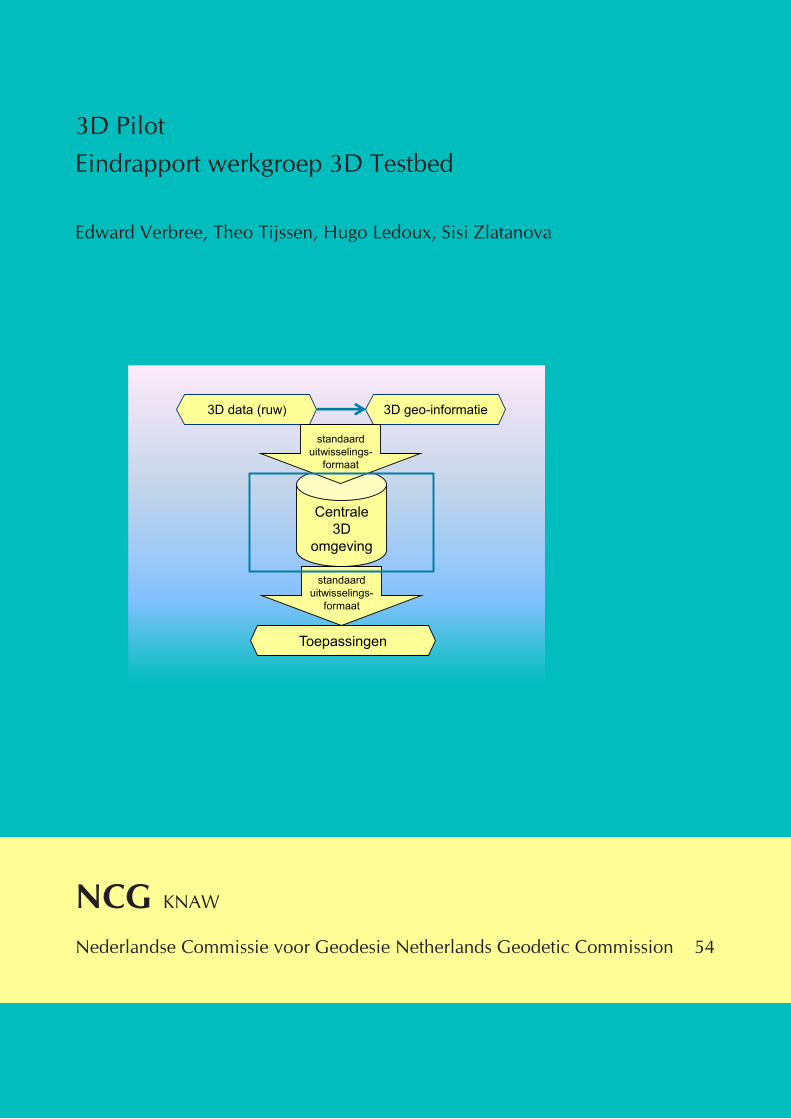
3D Pilot Eindrapport werkgroep 3D Testbed Edward Verbree, Theo Tijssen, Hugo Ledoux, Sisi Zlatanova NCG KNAW Nederlandse Commissie voor Geodesie Netherlands Geodetic Commission 54 Toepassingen Centrale 3D omgeving 3D data (ruw) standaard uitwisselings- formaat 3D geo-informatie standaard uitwisselings- formaat
Transcript of 3D Pilot. Eindrapport werkgroep 3D Testbed - GDMC Home · 3.3 CityGML op basis van extrusie 9 3.4...
3D PilotEindrapport werkgroep 3D Testbed
Edward Verbree, Theo Tijssen, Hugo Ledoux, Sisi Zlatanova
NCG KNAW
Nederlandse Commissie voor Geodesie Netherlands Geodetic Commission 54
Toepassingen
Centrale 3D
omgeving
3D data (ruw)
standaard uitwisselings-
formaat
3D geo-informatie
standaard uitwisselings-
formaat

3D Pilot
Eindrapport werkgroep 3D Testbed
Edward Verbree, Theo Tijssen, Hugo Ledoux, Sisi Zlatanova
NCG Nederlandse Commissie voor Geodesie Netherlands Geodetic Commission 54
Delft, januari 2012
3D Pilot. Eindrapport werkgroep 3D TestbedEdward Verbree, Theo Tijssen, Hugo Ledoux, Sisi ZlatanovaNederlandse Commissie voor Geodesie, Netherlands Geodetic Commission 54, 2012ISBN: 978 90 6132 332 7
Bureau van de Nederlandse Commissie voor GeodesieJaffalaan 9, 2628 BX DelftPostbus 5030, 2600 GA DelftTel.: 015 278 21 03Fax: 015 278 17 75E-mail: [email protected]: www.ncg.knaw.nl
De NCG is een onderdeel van de KNAW (Koninklijke Nederlandse Akademie van Wetenschappen).
Edward Verbree, TU DelftTheo Tijssen, TU DelftHugo Ledoux, TU DelftSisi Zlatanova, TU Delft
3D Pilot. Eindrapport werkgroep 3D Testbed iii
Inhoudsopgave
1. Inleiding 11.1 Doel van het 3D testbed 11.2 Focus 3D testbed: CityGML en 3DCityDB 11.3 Dankzegging 21.4 Leeswijzer 3
2. CityGML als informatiemodel 52.1 CityGML concept 52.2 Toepassingen van CityGML 52.3 Aansluiting op IMGeo 5
3. CityGML als uitwisselingsformaat 73.1 Uitwisseling van CityGML bestanden 73.2 Fouten in CityGML bestanden 7 3.2.1 Syntaxfouten 8 3.2.2 Semantische fouten 8 3.2.3 Textures 8 3.2.4 Implicit geometry 83.3 CityGML op basis van extrusie 93.4 CityGML in Nederland: Spatial Reference System 9
4. CityGML binnen 3DCityDB 114.1 Implementatie 114.2 Importer / Exporter tool 114.3 Import 124.4 Export 12
5. CityGML 3DCityDB direct access 175.1 Connect 3DCityDB using BentleyMap 175.2 Bentley Map Connect 19
6. Geometrische validiteit 216.1 Exchange and interoperability 216.2 Are your polyhedra the same as my polyhedra? 216.3 Validation in Oracle Spatial 11g 22 6.3.1 Oracle Spatial 11g validation tests 22 6.3.2 TU Delft extrusion software 23 6.3.3 ArcGIS 10 28 6.3.4 Bentley V8i 286.4 Validation with the Constrained Delaunay Tetrahedralization 28 6.4.1 Constrained Delaunay Tetrahedralization (CDT) 28 6.4.2 Our approach 28 6.4.3 Summary 29
7. Literatuur 31

iv 3D Pilot. Eindrapport werkgroep 3D Testbed
3D Pilot. Eindrapport werkgroep 3D Testbed 1
1. Inleiding
In de 3D Pilot – een initiatief van het Kadaster, Geonovum, de Nederlandse Commissie voor Geo-desie (NCG) en het ministerie van Infrastructuur en Milieu – hebben meer dan 60 organisaties het afgelopen jaar samengewerkt om toepassing van 3D geo-informatie een impuls te geven. Eén van de activiteiten van de 3D Pilot, uitgevoerd door de Sectie GIS-technologie van het Onderzoeksinsti-tuut OTB van de TU Delft, is het ontwikkelen van een testbed, die de samenwerking tussen al deze partijen technisch realiseert. De andere 3D Pilot activiteiten richtten zich op respectievelijk 3D data aanbod, 3D standaard NL en use cases. Dit rapport beschrijft de ervaringen van het TUD GIS-t team met het 3D testbed. Deze beschrijving is door de aard van de uitgevoerde werkzaamheden – testen, gebruikersondersteuning – kort en zakelijk. Daarbij is een deel van de tekst in het Engels. Veel re-sultaten zijn tijdens de verschillende 3D Pilot bijeenkomsten al eerder gecommuniceerd in de vorm van power point presentaties.
1.1 Doel van het 3D testbedEen testbed wordt wel omschreven als een specifieke onderzoeksomgeving voor het verrichten van experimenten met data en services, waarna de resultaten worden geëvalueerd en verspreid. En dat is precies wat het 3D testbed van de 3D Pilot het afgelopen jaar heeft gedaan. Op basis van de door de participanten beschikbaar gestelde data van het Rotterdamse testgebied Kop van Zuid zijn de mogelijkheden van 3D in het algemeen, en in het bijzonder CityGML als uitwisselingsformaat én als datamodel onderzocht. Dit is gedaan in een daarvoor speciaal ingerichte testbed-omgeving bij de TU Delft.
Het 3D testbed richtte zich op een drietal onderzoeksvragen. Allereerst is er gekeken naar de toe-pasbaarheid van 3D geo-informatie binnen de bedrijfsprocessen (use cases) van de deelnemers van de 3D Pilot. Is dit alleen voor communicatiedoeleinden (mooie plaatjes), is het doel vooral bereke-ningen en analyses, of moet de meerwaarde nog worden ontdekt? Vervolgens is de vraag gesteld op welke wijze deze 3D geo-informatie op bestandsniveau opgeslagen en uitgewisseld kan worden. En tot slot is er gekeken naar de meerwaarde van een centrale geo-DataBase Management System (DBMS) benadering voor zowel de bevraging als presentatie van de data in een 3D GIS-omgeving.
1.2 Focus 3D testbed: CityGML en 3DCityDBGedurende de uitvoering van het project is, in overleg met de 3D Pilot stuurgroep, met name ant-woord gegeven op de vraag hoe 3D geo-informatie geïntegreerd beheerd kan worden en vanuit deze centrale opslag op bestandsniveau bevraagd en gevisualiseerd kan worden. Vroegtijdig is besloten om daarbij te focussen op het concept en de toepassing van CityGML.
De sturende kracht achter CityGML is momenteel het Institute for Geodesy and Geoinformation Sci-ence, TU Berlin. Er is zeer veel informatie over het concept achter, de toepassing van CityGML en de 3DCityDB te vinden op www.citygml.org en www.citygml.org. CityGML wordt aldaar omschreven als:
"CityGML is a common information model for the representation of 3D urban objects. It defines the classes and relations for the most relevant topographic objects in cities and regional models with respect to their geometrical, topological, semantical and appearance properties. Included are gene-ralization hierarchies between thematic classes, aggregations, relations between objects, and spatial properties. These thematic information go beyond graphic exchange formats and allow to employ virtual 3D city models for sophisticated analysis tasks in different application domains like simulati-ons, urban data mining, facility management, and thematic inquiries."
De zogenaamde 3DCityDB database is uitgebreid ingezet voor zowel de validatie als de opslag en bevraging van CityGML bestanden die door de deelnemers van de 3D Pilot zijn aangeleverd:
2 3D Pilot. Eindrapport werkgroep 3D Testbed
"The 3D City Database is a free 3D geo database to store, represent, and manage virtual 3D city mo-dels on top of a standard spatial relational database. The database model contains semantically rich, hierarchically structured, multi-scale urban objects facilitating complex GIS modeling and analysis tasks, far beyond visualization."
Het dient daarbij te worden benadrukt dat voor veel partijen – ook voor de grotere GIS bedrijven – het concept achter CityGML én de syntax en de schemadefinities nieuw waren. Door uitgebreide e-mailcorrespondentie en de terugkoppeling van de resultaten tijdens de 3D Pilot bijeenkomsten heeft dit bij de meest betrokken deelnemers van de 3D Pilot geleid tot een groter begrip van CityGML. In deze rapportage schetsen wij een aantal problemen waar wij – en daarmee ook de deelnemers van de 3D Pilot – tegenaan zijn gelopen; het is echter geen uitputtend verslag of een complete handlei-ding CityGML. Er is minder tot geen aandacht besteed aan geschikte webservices en de performance issues.
Wel is er uitgebreid gekeken naar de zogenaamde geometrische validiteit, onder het motto: "Are your polyhedra the same as my polyhedra?". Zodra een 'solid' (volume) voorzien wordt van texturen valt deze uiteen in een aantal losse deelvlakken. Voor veel analyses is het noodzakelijk dat deze deelvlakken een gesloten, waterdicht, geheel vormen. Het datamodel van CityGML dwingt deze geometrische eis echter niet af. Binnen Oracle Spatial bestaat de mogelijkheid op deze geometrische validiteit te toetsen. Een andere optie die binnen het testbed is onderzocht, is gebaseerd op het idee van een opdeling van de ruimte door middel van een tetrahedralisatie. De deelvlakken bakenen dan een ruimte af die wordt opgedeeld in tetraëders. Als deze alle onderling verbonden zijn, dan zijn de deelvlakken ook onderling met elkaar verbonden en is er sprake van een solid. De implementatie van deze methode is bij het afsluiten van de pilot nog in uitvoering.
1.3 DankzeggingZoals gezegd: het 3D testbed heeft de samenwerking en kennisverspreiding tussen de deelnemers van de 3D Pilot gestimuleerd. Min of meer officiële momenten waren daarvoor de 3D Pilot bijeen-komsten, vooral ook als platform waar eindgebruikers, ontwikkelaars, leveranciers, onderzoeksin-stellingen en universiteiten elkaar vanuit een nieuwsgierige en leergierige instelling troffen.
Daarbij willen we een aantal partijen nadrukkelijk bedanken voor hun medewerking en het aan-leveren van uitdagend testmateriaal. Annet Groneman (Toposcopie) heeft zeer veel werk verzet in het vervaardigen van een uitgebreide CityGML-maquette van de Kop van Zuid; Erik Vriend (iDelft) heeft tijdens de uitvoering van de 3D Pilot een krachtige en zeer bruikbare CityGML conversietool vervaardigd, en Kees van Prooijen heeft namens Bentley diverse tools ingezet. Veel afbeeldingen in dit rapport zijn vervaardigd aan de hand van hun bronmateriaal.
In het kader van de 3D Pilot is er uitgebreid (e-mail) contact geweest met Gerhard Juen om de mo-gelijkheden van de CityGML-Toolchain te bespreken. Met Benoit Neil van het bedrijf Virtuel City is uitgebreid contact geweest over het testen van hun RCP-Transformer en RCP-Manager voor het beheer van 3D data binnen een ESRI GIS-omgeving. Vanuit ESRIi Redland (USA) was het directe contact met de 3D Product Manager Gert van Maren wederom een genoegen en de preview van zijn demo's over de 3D functionaliteit in ArcGIS 10 zeer inspirerend. Dat geldt in het bijzonder ook voor zijn komst naar het preconference seminar 'ArcGIS 10: een compleet 3D GIS' van ESRI Nederland op 21 september 2010. Intergraph's 3D Product Manager Danny Kita heeft tijdens een bezoek op 11 oktober 2010 de mogelijkheden van Geomedia3D gedemonstreerd. Met Benoit Fréedéricque zijn op 10 maart 2011 uitgebreid de mogelijkheden en de visie van Bentley’s 3D City GIS besproken.
Een min of meer officiële afsluiting van de activiteiten van het 3D testbed was de '100% CityGML workshop' op 14 maart 2011 in de Aula van de TU Delft. De komst van en de presentaties van Tho-mas Kolbe en Javier Herreruela werden zeer hoog gewaardeerd.
Tot slot: het uitvoeren van werkzaamheden in het kader van een 3D testbed vereist zeer veel toe-wijding en geduld. Het opzetten van een goede testomgeving, de installatie en 'tunen' van de juiste
3D Pilot. Eindrapport werkgroep 3D Testbed 3
software en databases, het inladen van een tal van min of meer valide CityGML bestanden, en het rapporteren van deze handelingen is werk dat veelal in de 'stille' uren plaats heeft gevonden. Dit werk is eigenlijk ook nooit af, want er is altijd 'meer' te onderzoeken. Bij deze dan ook een speci-aal woord van dank aan Theo Tijssen die de faciliteiten van het Geo-Database Management Center (www.gdmc.nl) van de TU Delft heeft benut.
1.4 LeeswijzerDit rapport is geen één-op-één verslag van alle uitgevoerde werkzaamheden van het 3D testbed. Zeer veel informatie is al verspreid tijdens de 3D Pilot bijeenkomsten. De verslagen van de presen-taties zijn terug te vinden op: www.geonovum.nl/nieuws/3D Pilot.
Dit rapport probeert wel de drie onderzoeksvragen op een generieke wijze te behandelen, met in hoofdstuk 2 het vraagstuk van de toepasbaarheid van 3D informatie vanuit het CityGML informa-tiemodel en in hoofdstuk 3 de opslag en uitwisseling van deze 3D informatie volgens het CityGML uitwisselingsformaat. In hoofdstuk 4 wordt de meerwaarde van de CityGML database implementatie (3DCityDB) aangetoond, met in hoofdstuk 5 de mogelijkheden van een 'direct connect' naar deze 3DCityDB database. Vervolgens gaat hoofdstuk 6 in op de geometrische validiteit. Eén en ander wordt geïllustreerd met een aantal praktische handleidingen en gedeeltes van power point presen-taties. De internationale setting van de deelnemers van het 3D testbed komt tot uiting in een aantal Engelstalige passages.
De voornaamste bevindingen worden in ieder hoofdstuk afgehandeld; het rapport sluit daarom niet af met een apart hoofdstuk 'conclusies en aanbevelingen'. Een andere bron van informatie zijn de handouts van de '100% CityGML Workshop'.
1. Basics of CityGML: initiation, representation of 3D urban models, OGC-standard [Thomas Kolbe].2. Applications of CityGML: overview of existing 3D citymodels, CityGML utilization [Thomas
Kolbe].3. CityGML file-based storage and exchange (conversion tools) [Edward Verbree].4. CityGML viewers [Edward Verbree].5. CityGML LOD1/LOD2 creation: polygon and planar map extrusion [Hugo Ledoux].6. CityGML geometry validation [Hugo Ledoux].7. CityGML DBMS storage (3DCityDB implementation, semantic validation) [Javier Herreruela].8. CityGML database connection [Sisi Zlatanova].9. CityGML semantic enrichment (Application Domain Extensions) [Sisi Zlatanova].10. CityGML mapping Dutch Profiles and Standards [Sisi Zlatanova].
Deze handouts zijn terug te vinden op de dataserver van het 3D Pilot project:http://gis.geo.tudelft.nl/3Dpilot/Presentaties/Cursus/ (user: pilot3D; password: Nederland3D).

4 3D Pilot. Eindrapport werkgroep 3D Testbed
3D Pilot. Eindrapport werkgroep 3D Testbed 5
2. CityGML als informatiemodel
Al in een vroeg stadium van de 3D Pilot is er voor gekozen om bij de beantwoording van deze vragen CityGML centraal te stellen. Deze Open Geospatial Consortium (OGC) standaard vindt zijn oorsprong in de universitaire wereld in Duitsland (Bonn, TU Berlijn) en is daar al veelvuldig toe-gepast voor 3D modelering en visualisatie van stedelijk gebied. Een uitgebreid overzicht van alle mogelijkheden van CityGML is te vinden op: www.citygml.org. CityGML wordt veelal gezien als een uitwisselingsformaat, maar het is ook – en vooral – een informatiemodel voor de representatie van ruimtelijke objecten in een stedelijke omgeving. In het kader van de 3D Pilot is de OGC standaard uitgebreid beschreven in hoofdstuk 4 van de rapportage van de werkgroep 3D Standaarden. Hier, in deze rapportage, richten we ons op de toepasbaarheid van CityGML.
2.1 CityGML conceptCityGML maakt op geometrisch èn op semantisch niveau een onderscheid tussen de thematische gebieden (gebouwen, vegetatie, water, terrein, etc.), maar doet dit ook – per object – op verschil-lende schaalniveaus. Een gebouwobject kan daarbij variëren van een eenvoudig blokmodel (LOD1), opgewerkt met dakvormen (LOD2), met vlakken met gaten voor het modeleren van ramen, deuren en andere exterieurkenmerken (LOD3), tot een volledig uitgewerkt interieurmodel (LOD4) al dan niet voorzien van textuurinformatie (appearance).
2.2 Toepassingen van CityGMLIn iedere presentatie over CityGML wordt benadrukt dat 3D City Modeling veel meer is dan puur en alleen 3D visualisatie; de geometry en appearance zijn slechts één aspect. Betekenisvolle objecten – met semantische eigenschappen – maken complexe bevragingen mogelijk als:
– From which windows in which rooms from which buildings do I have visible coverage of a certain place, road, or monument?
– To what floors have all buildings in a flooded area been affected?
De antwoorden op deze vragen kunnen worden ondersteund met een toepasselijke 3D visualisatie, maar deze visualisatie is daarvoor niet strikt noodzakelijk.
2.3 Aansluiting op IMGeoObjecten kunnen al dan niet bewust op een semantisch verkeerde manier zijn benoemd of op een niet geëigend LOD niveau zijn gedefinieerd. Een oud probleem, want Alice in Wonderland ver-Een oud probleem, want Alice in Wonderland ver-zuchtte al: "The question is, whether you can make words mean so many different things". CityGML biedt nu eenmaal veel vrijheid voor semantische en geometrische combinaties. Er kunnen seman-tische rijke modellen (LOD2) met beperkte geometrische representaties (bijvoorbeeld blokmodel-len) gekoppeld worden. In dit opzicht zijn de Nederlandse informatiemodellen rijker aan regels en definities. Zo brengt IMGeo (het informatiemodel voor grootschalige topografie) wel eenheid in definities en afbakening. Daarom was het interessant om te evalueren hoe IMGeo en CityGML op elkaar aansluiten. Deze afstemming is binnen een andere activiteit van de 3D Pilot afgehandeld (3D Standaard NL).

6 3D Pilot. Eindrapport werkgroep 3D Testbed
3D Pilot. Eindrapport werkgroep 3D Testbed 7
3. CityGML als uitwisselingsformaat
CityGML als intern informatiemodel is nieuw in commerciële GIS-omgevingen en dringt langzaam door in systemen van onder andere Bentley, ESRI en Intergraph.
3.1 Uitwisseling van CityGML bestandenZo is het in Bentley Map mogelijk om CityGML bestanden te exporteren en ook te importeren via een op FME geënte data interoperability component. Pas zeer recent is een specifieke mapping van CityGML naar het Bentley XML Feature Modelling (FM) schema beschikbaar. Met dit schema is het mogelijk om 'from scratch' betekenisvolle en geometrisch valide 3D (deel)objecten op te bouwen en te manipuleren.
Tijdens de 3D Pilot heeft een aantal deelnemers zich zeer sterkt gericht op het beschikbaar maken van 3D maquettes van het testgebied Kop van Zuid binnen de structuur van CityGML. Zij hebben zich daarbij met name gericht op de 3D geometrie in een aantal LOD's en de aankleding ('textures') van deze geometrieën.
Bij het opbouwen van deze 3D maquettes volgens CityGML is het van belang dat de gebruikte software een zeer goed begrip heeft van de schemadefinitie en de interne structuur van de CityGML bestanden.
Een van de mogelijkheden om een CityGML bestand te maken is door middel van SketchUp (sofware voor het maken van 3D modellen voor gebruik in bijvoorbeeld Google Earth). In deze sofware is een plugin voor CityGML beschikbaar. Hoewel het CityGML datamodel hier zo goed als mogelijk is ver-weven in de SketchUp omgeving blijkt deze koppeling toch ook nog problematisch. De XML syntax van het CityGML bestand moet correct zijn en voldoen aan de CityGML schemadefinities. Veelal geschiedt de test of dit daadwerkelijk zo is door het geproduceerde CityGML bestand te importeren in één van de beschikbare viewers als LandXplorer, FZK Viewer, of de FME Data Inspector. Als deze visualisatie goed oogt, dan wordt het geëxporteerde CityGML bestand correct bevonden. Helaas is uit onze tests gebleken dat deze viewers vaak wat vergevingsgezind zijn en wordt vervolgens een niet geheel valide CityGML bestand verder verspreid.
3.2 Fouten in CityGML bestandenEen belangrijk onderscheid bij het optreden van 'fouten' in CityGML (en in het algemeen GML bestanden) heeft te maken met het verschil tussen 'syntax' (de vorm) en 'semantiek' (de inhoud of betekenis).
Het is moeilijk om aan te geven welk type 'fout' het meest voorkomt in CityGML bestanden. Proble-men met de syntax zijn makkelijk te constateren en ze zijn ook veelvuldig geconstateerd tijdens de 3D Pilot. Op zich is dat wat merkwaardig want, omdat ze makkelijk te constateren zijn, zijn ze in principe ook relatief eenvoudig te voorkomen.
Door het valideren van een GML bestand kan men eenvoudig vaststellen of de syntax correct is. Bij een incorrecte syntax krijgt men foutmeldingen over waar en waarom een element van een GML bestand niet juist is. Het valideren vindt plaats op twee niveaus: er wordt in de eerste plaats gecon-troleerd of het bestand aan de basisregels van XML voldoet (correct gebruik van begin- en eindtags, correcte 'nesting' van tags, gebruik van de juiste datatypes, etc.). Op een tweede niveau van validatie wordt gecontroleerd of een CityGML bestand overeenstemt met de 'schema definition' voor dat type bestanden. CityGML is gedefinieerd als een verzameling van 'schemas' (een datamodel) voor allerlei typen 3D objecten in een stedelijke omgeving. De 'schemas' schrijven voor welke type elementen (en met welke syntax) voor mogen komen in een CityGML bestand. Als de regels vastgelegd in de 'schemas' niet correct worden toegepast in een bestand dan worden bij de validatie deze als fouten aangemerkt.
8 3D Pilot. Eindrapport werkgroep 3D Testbed
3.2.1 SyntaxfoutenEnkele voorbeelden van syntaxfouten die zijn vastgesteld tijdens de 3D Pilot bij aangeleverde Ci-tyGML bestanden:
– Het niet-correct verwijzen naar gebruikte 'schemas' (waardoor vervolgens alle CityGML elemen-ten gedefinieerd in dat schema als 'fout' worden bestempeld).
– Het weglaten van elementen die verplicht zijn (bijvoorbeeld bij het opgeven van een 'measu-redHeight' bij een gebouw is het verplicht om bij die hoogte ook een eenheid op te geven, het weglaten van de eenheid is fout).
– Het gebruik van incorrecte ID's (bijvoorbeeld voor een gml:id geldt dat deze moet beginnen met een letter, een cijfer als eerste karakter is onjuist).
– Een verkeerd format bij het opgeven van een 'date'.– Het opgeven van lege elementen waar dat niet mag.– Het verwijzen naar texture files die niet bestaan.
3.2.2 Semantische foutenFouten die te maken hebben met de 'semantiek' (de inhoud of betekenis van data) zijn in enkele gevallen makkelijk vast te stellen, maar meestal zal dit vrij lastig zijn. Visuele inspectie van sommige bestanden maakte duidelijk dat er allerlei problemen met de geometrie waren. Als echter in een CityGML bestand een object als water is geclassificeerd, terwijl dat eigenlijk terrein zou moeten zijn dan kan men dat alleen ontdekken bij een nauwkeurige kwaliteitscontrole van de data. Hetzelfde geldt bijvoorbeeld als er een textuur aan het verkeerde gebouw is gekoppeld. In bepaalde gevallen kan er van 'redundantie' in de data gebruik worden gemaakt voor inhoudelijke kwaliteitscontroles. Van gebouwen is bijvoorbeeld meestal de hoogte bekend, het aantal verdiepingen is beschikbaar als attribuut en er is geometrie aanwezig. Deze attributen kun je met elkaar vergelijken en nagaan of er (grove) inconsequenties optreden. Een gebouw van 10 verdiepingen dat 6 m hoog is lijkt niet erg plausibel. Men moet overigens wel meer van de gegevens weten voor het verantwoord is dit soort kwaliteitscontroles toe te passen. De iDelft 3D Dataconverter bijvoorbeeld gebruikt de hoogte om de geometrie te genereren en om het aantal verdiepingen in te vullen. Dit leidt tot consistente gege-vens die echter niet per se correct zijn. Voor een betere grip op de kwaliteit is het nodig voldoende metadata toe te voegen aan de gegevens (over de herkomst van de data en de bewerkingen die er op uitgevoerd zijn).
3.2.3 TexturesEen specifiek probleem bij het afhandelen van textures is aangetoond op basis van het CityGML bestand van Toposcopie. De syntax is correct en semantisch ziet deze er ook goed uit. Dit CityGML valideert dus goed, en wordt ook goed ingelezen in de 3DCityDB. Het exporteren ging echter niet goed. Het probleem is dat bij exporteren alle texture files in 1 directory terechtkomen (in de 3DCi-tyDB worden van textures het bestand zelf en de bestandsnaam opgeslagen, niet het oorspronkelijk pad dat naar het bestand verwijst). In het oorspronkelijke bestand zijn voor de textures een heleboel verschillende (sub)directories gebruikt waarin dan vaak bestanden met dezelfde naam voorkomen, er zijn bijvoorbeeld 24 verschillende textures met de naam 'image1.jpg'. Bij exporteren wordt de betreffende texture 23 keer overschreven en dus zijn er ook 23 'surfaces' die aan een verkeerde 'ap-pearance' zijn gekoppeld. De les is dus dat alle texture files gebruikt bij CityGML een unieke naam moeten hebben.
3.2.4 Implicit geometryIn hetzelfde bestand komen zeer veel bomen (vegetatie) voor. Deze worden zeer slim – en ook vol-gens de regels van CityGML – eenmalig als een implicit geometry opgeslagen. Dat betekent dat één boom een volledige geometrie heeft en alle andere bomen op basis van een transformatiematrix een plek in de wereld krijgen. Bij een export vanuit de 3DCityDB worden echter de geometrieën van alle bomen opgebouwd, met als gevolg dat de oorspronkelijke bestandsgrootte explodeert en veel viewers (waaronder LandXplorer) laat crashen.
3D Pilot. Eindrapport werkgroep 3D Testbed 9
3.3 CityGML op basis van extrusieEen andere methode voor het opbouwen van een CityGML bestand is om 2D gebouw 'footprints' op basis een hoogte-attribuut 'omhoog te trekken' tot 3D LOD1 objecten. Een goed voorbeeld van deze aanpak is de 3D data converteertool van het bedrijf iDelft welke tijdens de 3D Pilot is ontwikkeld. Als de 'footprints' van de gebouwen op elkaar aansluiten, dan is het ook mogelijk een topologisch correct CityGML LOD1 bestand aan te maken volgens de methode beschreven in www.gdmc.nl/pu-blications/2009/Extruding_building_footprints.pdf. Dit artikel van Hugo Ledoux en Martijn Meijers is in april 2011 verschenen in het International Journal of Geographical Information Science.
3.4 CityGML in Nederland: Spatial Reference SystemEen specifiek probleem voor Nederland is het te hanteren Spatial Reference System EPSG:7415, een samengesteld SRS met RD voor de XY dimensie (EPSG:28992) en NAP voor de Z dimensie (EPSG:5709). Deze EPSG wordt nog niet ondersteund door Oracle Spatial, hetgeen wat handigheid vereist bij de installatie van de database. Een andere mogelijkheid is om alleen de SRS voor de XY dimensie te gebruiken: EPSG 28992.

10 3D Pilot. Eindrapport werkgroep 3D Testbed
3D Pilot. Eindrapport werkgroep 3D Testbed 11
4. CityGML binnen 3DCityDB
De 3D City Database (3DCityDB) is een implementatie van het CityGML datamodel in een DBMS (Database Management System), ontwikkeld door TU Berlin en gratis beschikbaar. Deze hebben we geïmplementeerd in het 3D testbed. We hebben gekozen voor Oracle Spatial als DBMS omdat dit de benodigde functionaliteit biedt. Maar implementatie in andere DBMS'en is zeker mogelijk, of zal dat binnenkort zijn. De eerste en vooralsnog enige toepassing die gebruikt maakt van de 3D City Database is een gebruiksvriendelijke import/export tool met een aantal mogelijkheden voor de selectieve opslag en bevraging van CityGML bestanden. Alvorens tot opslag in de database over te gaan kan het aangeboden CityGML bestand gevalideerd worden op de schema definities. Deze controle maakt het vervolg – CityGML als uitwisselingsformaat – erg prettig.
4.1 ImplementatieEr zijn drie stappen doorlopen om CityGML bestanden in de database op te slaan:
– Prepareren van de Oracle database; er dient een account aangemaakt te worden met de benodigde rechten en tevens dient men er voor te zorgen dat de SRS'en die men wil gebruiken beschikbaar zijn (hetgeen standaard met EPSG:7415 niet het geval is in Oracle).
– Initialiseren van de 3D City Database; de 3D City Database bestaat uit een behoorlijk aantal ta-bellen met daartussen allerlei relaties, het aanmaken van deze structuur met de bijbehorende 'se-quences', 'triggers', 'constraints' en dergelijke wordt verzorgd door het uitvoeren van een aantal meegeleverde SQL scripts.
– Importeren van een CityGML bestand met de import/export tool. Zowel bij het importeren als bij het exporteren naar/van de 3D City Database is het mogelijk om selecties te maken: op basis van object ID, naam, objectnummer en/of een 'bounding box'.
De initialisatie van de 3D City Database en de implementatie van de import/export en validatie tools hebben we gerealiseerd in het testbed. Vervolgens waren de import/export en validatie tools beschik-baar voor alle 3D Pilot deelnemers om data te up- en downloaden.
4.2 Importer / Exporter toolDe 3D City Database is zoals ieder DBMS, het is een schema waar men gegevens in kan stoppen en gegevens uit kan halen. Zonder een college databases te gaan geven, zijn er een heleboel redenen om een database te gebruiken (zoals veilige, centrale opslag, uniforme toegang middels SQL, goed geregelde toegang en beveiliging van gebruikers, van overal op het internet te benaderen, snelle zoekmethoden door het gebruik van indexen, etc.). Dit wil niet zeggen dat een database altijd de beste oplossing is, er zijn veel situaties denkbaar waarin een andere oplossing net zo goed of beter of handiger is. De Importer / Exporter tool van de 3D City Database is bedoeld om CityGML data tussen de database en CityGML bestanden te transporteren. Zowel bij het inlezen (importeren) als het opvragen (expor-teren) kan geselecteerd worden. De selectie kan plaatsvinden op gml:id, gml:name, een (range van) objectnummers, bounding box en feature classes (en op een combinatie hiervan). Ook is er nog een soort 'clean-up' functie om bijvoorbeeld gebouwen die elkaar (deels) overlappen op te schonen.
In principe is het zo dat men met gebruik van SQL en database functies allerlei operaties op de gegevens in een database kan uitvoeren. Als het om geografische gegevens gaat kan men zo vele GIS-achtige operaties uitvoeren op de database. In het geval van de 3D City Database ligt dat wat moeilijker want de gegevens zijn opgeslagen in een specifieke, soms vrij complexe structuur. De geometrie bijvoorbeeld is uiteindelijk opgeslagen als losse vlakken in een tabel. Via allerlei verwij-zingen (primary and foreign keys) zijn de vlakken van een object terug te vinden, maar daarvoor moet men dan wel de verwijzingen volgen (met andere woorden, men kan niet met een simpel SQL statement de geometrie van een gebouw opvragen). Op zich kan men goed een toepassing maken die 'begrijpt' hoe een 3D City Database in elkaar zit en daar dan allerlei operaties op loslaten, maar
12 3D Pilot. Eindrapport werkgroep 3D Testbed
vooralsnog is deze er niet echt. Wat men nu heeft is de Importer / Exporter tool waarmee gegevens ingevoerd en opgevraagd kunnen worden, met daarbij filtermogelijkheden.
Het eerste wat men nodig heeft bij gebruik van de 3D City Database is een geschikt (op de juiste manier geinitialiseerd) database account. Voor de 3D Pilot hebben we er daar een aantal van aan-gemaakt.
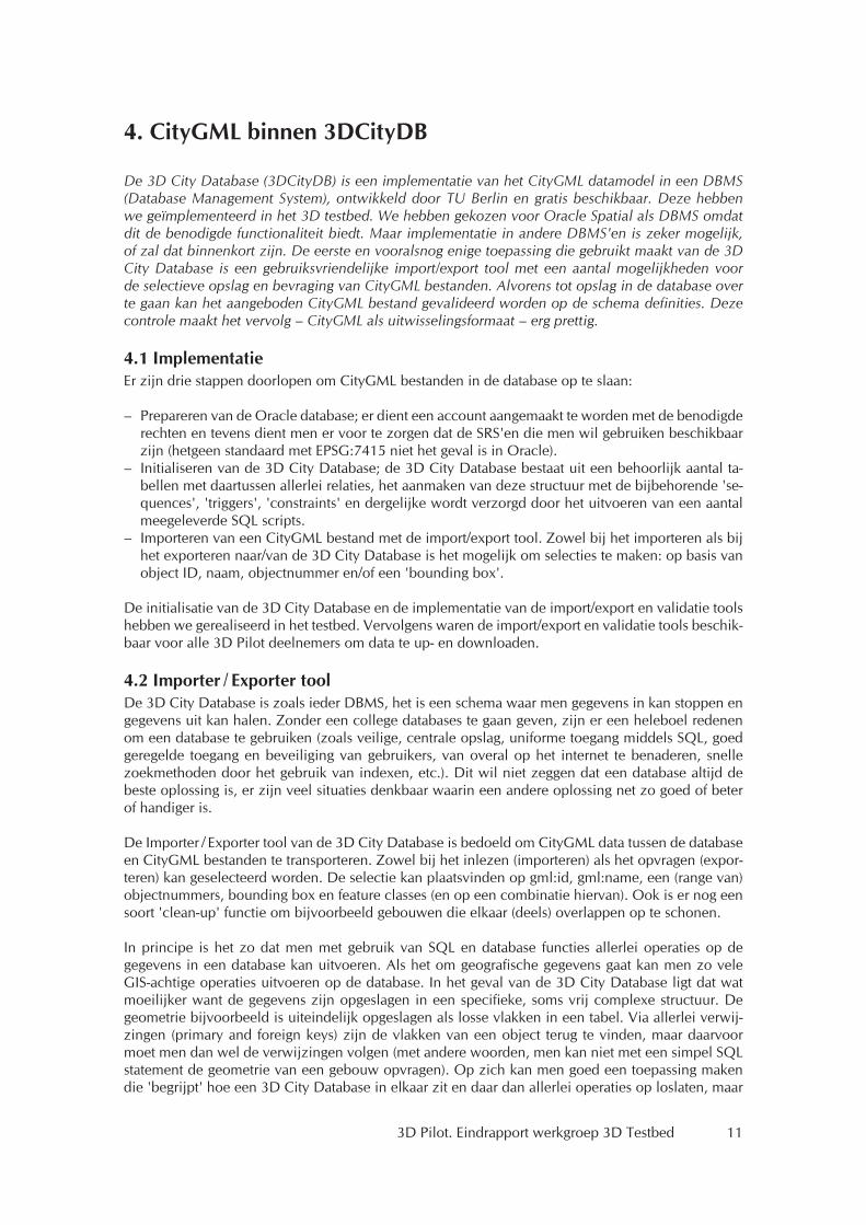
In dit hoofdstuk maken we gebruik van de CityGML maquette van Toposcopie. Deze is te benaderen met deze settings (let op: screendumps verwijzen naar andere user setting):
host: gis.geo.tudelft.nlport: 1521database: gis112user: pilot3d_02password: Nederland3D
In de Importer / Exporter ziet dat er als volgt uit (figuur 1):
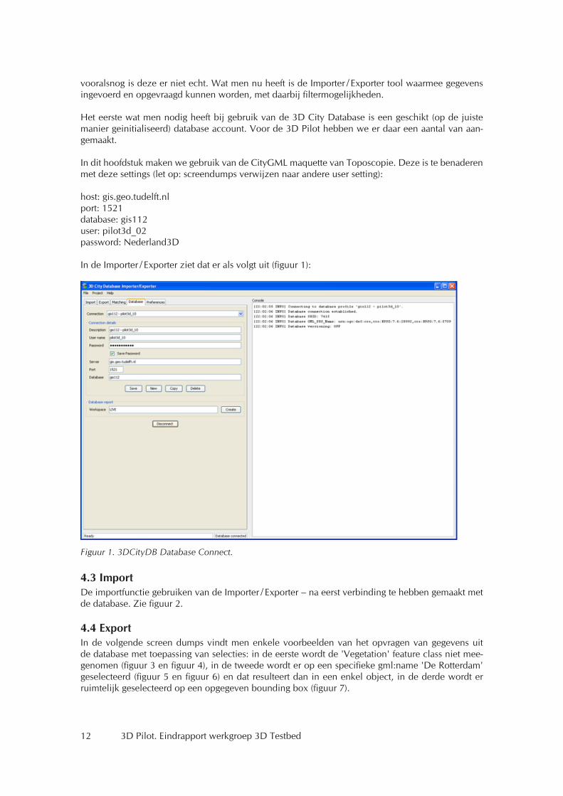
4.3 ImportDe importfunctie gebruiken van de Importer / Exporter – na eerst verbinding te hebben gemaakt met de database. Zie figuur 2.
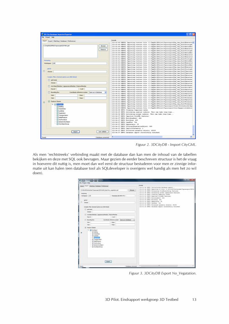
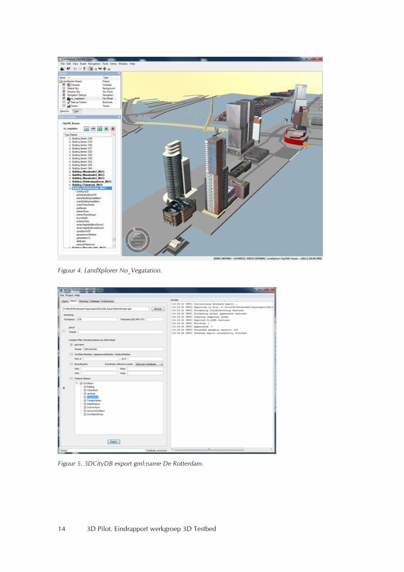
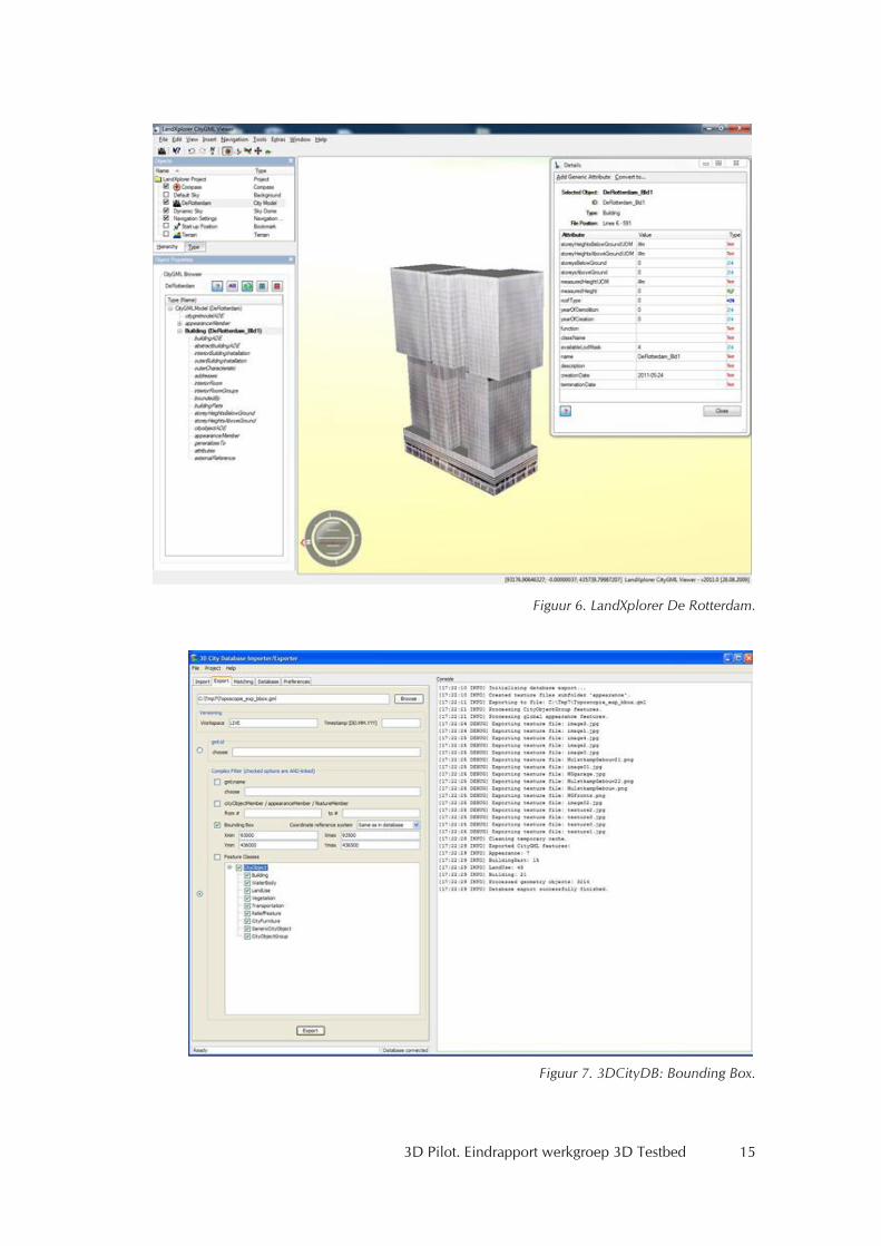
4.4 ExportIn de volgende screen dumps vindt men enkele voorbeelden van het opvragen van gegevens uit de database met toepassing van selecties: in de eerste wordt de 'Vegetation' feature class niet mee-genomen (figuur 3 en figuur 4), in de tweede wordt er op een specifieke gml:name 'De Rotterdam' geselecteerd (figuur 5 en figuur 6) en dat resulteert dan in een enkel object, in de derde wordt er ruimtelijk geselecteerd op een opgegeven bounding box (figuur 7).
Figuur 1. 3DCityDB Database Connect.
3D Pilot. Eindrapport werkgroep 3D Testbed 13
Als men 'rechtstreeks' verbinding maakt met de database dan kan men de inhoud van de tabellen bekijken en deze met SQL ook bevragen. Maar gezien de eerder beschreven structuur is het de vraag in hoeverre dit nuttig is, men moet dan wel eerst de structuur bestuderen voor men er zinnige infor-matie uit kan halen (een database tool als SQLdeveloper is overigens wel handig als men het zo wil doen).
Figuur 2. 3DCityDB - Import CityGML.
Figuur 3. 3DCityDB Export No_Vegatation.
14 3D Pilot. Eindrapport werkgroep 3D Testbed
Figuur 4. LandXplorer No_Vegatation.
Figuur 5. 3DCityDB export gml:name De Rotterdam.
3D Pilot. Eindrapport werkgroep 3D Testbed 15
Figuur 6. LandXplorer De Rotterdam.
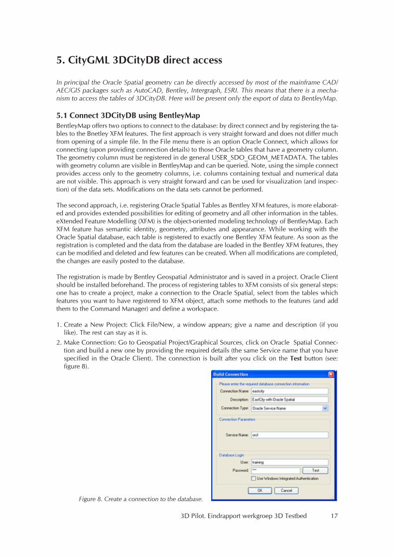
Figuur 7. 3DCityDB: Bounding Box.

16 3D Pilot. Eindrapport werkgroep 3D Testbed
3D Pilot. Eindrapport werkgroep 3D Testbed 17
5. CityGML 3DCityDB direct access
In principal the Oracle Spatial geometry can be directly accessed by most of the mainframe CAD/AEC/GIS packages such as AutoCAD, Bentley, Intergraph, ESRI. This means that there is a mecha-nism to access the tables of 3DCityDB. Here will be present only the export of data to BentleyMap.
5.1 Connect 3DCityDB using BentleyMapBentleyMap offers two options to connect to the database: by direct connect and by registering the ta-bles to the Bnetley XFM features. The first approach is very straight forward and does not differ much from opening of a simple file. In the File menu there is an option Oracle Connect, which allows for connecting (upon providing connection details) to those Oracle tables that have a geometry column. The geometry column must be registered in de general USER_SDO_GEOM_METADATA. The tables with geometry column are visible in BentleyMap and can be queried. Note, using the simple connect provides access only to the geometry columns, i.e. columns containing textual and numerical data are not visible. This approach is very straight forward and can be used for visualization (and inspec-tion) of the data sets. Modifications on the data sets cannot be performed.
The second approach, i.e. registering Oracle Spatial Tables as Bentley XFM features, is more elaborat-ed and provides extended possibilities for editing of geometry and all other information in the tables. eXtended Feature Modelling (XFM) is the object-oriented modeling technology of BentleyMap. Each XFM feature has semantic identity, geometry, attributes and appearance. While working with the Oracle Spatial database, each table is registered to exactly one Bentley XFM feature. As soon as the registration is completed and the data from the database are loaded in the Bentley XFM features, they can be modified and deleted and few features can be created. When all modifications are completed, the changes are easily posted to the database.
The registration is made by Bentley Geospatial Administrator and is saved in a project. Oracle Client should be installed beforehand. The process of registering tables to XFM consists of six general steps: one has to create a project, make a connection to the Oracle Spatial, select from the tables which features you want to have registered to XFM object, attach some methods to the features (and add them to the Command Manager) and define a workspace.
1. Create a New Project: Click File/New, a window appears; give a name and description (if you like). The rest can stay as it is.
2. Make Connection: Go to Geospatial Project/Graphical Sources, click on Oracle Spatial Connec-tion and build a new one by providing the required details (the same Service name that you have specified in the Oracle Client). The connection is built after you click on the Test button (see: figure 8).
Figure 8. Create a connection to the database.
18 3D Pilot. Eindrapport werkgroep 3D Testbed
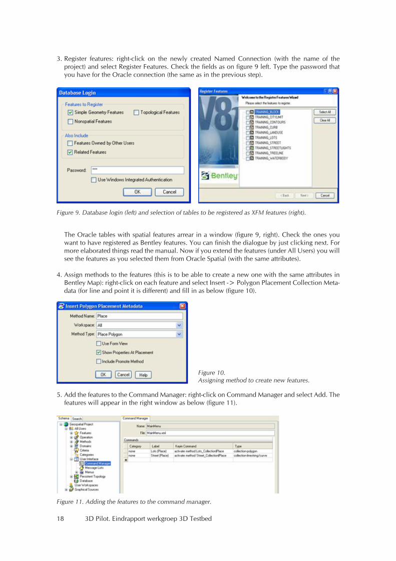
3. Register features: right-click on the newly created Named Connection (with the name of the project) and select Register Features. Check the fields as on figure 9 left. Type the password that you have for the Oracle connection (the same as in the previous step).
The Oracle tables with spatial features arrear in a window (figure 9, right). Check the ones you want to have registered as Bentley features. You can finish the dialogue by just clicking next. For more elaborated things read the manual. Now if you extend the features (under All Users) you will see the features as you selected them from Oracle Spatial (with the same attributes).
4. Assign methods to the features (this is to be able to create a new one with the same attributes in
Bentley Map): right-click on each feature and select Insert -> Polygon Placement Collection Meta-data (for line and point it is different) and fill in as below (figure 10).
5. Add the features to the Command Manager: right-click on Command Manager and select Add. The features will appear in the right window as below (figure 11).
Figure 9. Database login (left) and selection of tables to be registered as XFM features (right).
Figure 10. Assigning method to create new features.
Figure 11. Adding the features to the command manager.
3D Pilot. Eindrapport werkgroep 3D Testbed 19
6. Create Workspace: Go to User Workspace, right-click and select Add.
5.2 Bentley Map ConnectWhen everything is completed, there are two ways to open the project:
1. Via Bentley Geospatial Administrator: load the project, list User Workspaces, click on the Work-space with the project that you need, click on the icon of Bentley Map that appears on the main toolbar (it is not visible otherwise).
2. Via Bentley Map: Select File/Open Oracle Spatial, right-click Oracle and select Open Graphical Source: <name project>. Note if you do not have created a project in Bentley Geospatial Admin-istrator, this field is not visible (i.e. only New Oracle Connection and Open Oracle XML are there).
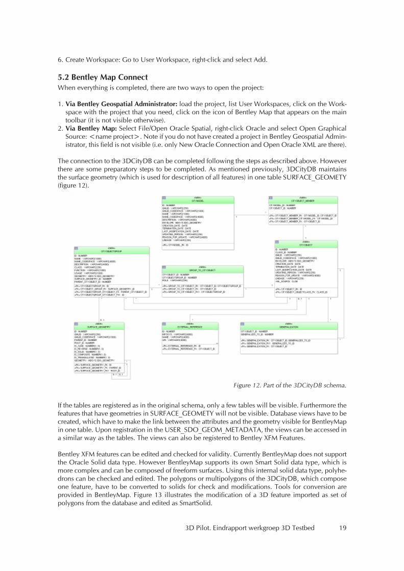
The connection to the 3DCityDB can be completed following the steps as described above. However there are some preparatory steps to be completed. As mentioned previously, 3DCityDB maintains the surface geometry (which is used for description of all features) in one table SURFACE_GEOMETY (figure 12).
If the tables are registered as in the original schema, only a few tables will be visible. Furthermore the features that have geometries in SURFACE_GEOMETY will not be visible. Database views have to be created, which have to make the link between the attributes and the geometry visible for BentleyMap in one table. Upon registration in the USER_SDO_GEOM_METADATA, the views can be accessed in a similar way as the tables. The views can also be registered to Bentley XFM Features.
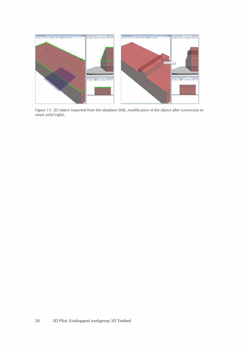
Bentley XFM features can be edited and checked for validity. Currently BentleyMap does not support the Oracle Solid data type. However BentleyMap supports its own Smart Solid data type, which is more complex and can be composed of freeform surfaces. Using this internal solid data type, polyhe-drons can be checked and edited. The polygons or multipolygons of the 3DCityDB, which compose one feature, have to be converted to solids for check and modifications. Tools for conversion are provided in BentleyMap. Figure 13 illustrates the modification of a 3D feature imported as set of polygons from the database and edited as SmartSolid.
Figure 12. Part of the 3DCityDB schema.
20 3D Pilot. Eindrapport werkgroep 3D Testbed
Figure 13. 3D object imported from the database (left), modification of the object after conversion to smart solid (right).
3D Pilot. Eindrapport werkgroep 3D Testbed 21
6. Geometrische validiteit
Binnen het 3D testbed is ook gekeken naar de zogenaamde geometrische validiteit, onder het motto: "Are your polyhedra the same as my polyhedra?". Zodra een 'solid' (volume) voorzien wordt van texturen valt deze uiteen in een aantal losse deelvlakken. Voor veel analyses is het noodzakelijk dat deze deelvlakken een gesloten, waterdicht, geheel vormen. CityGML dwingt deze geometrische eis echter niet af.
6.1 Exchange and interoperabilityTo facilitate and encourage the exchange and interoperability of geographical information, the ISO and the OGC have developed in recent years standards that define what the basic geographical primitives are (ISO, TC211), and also how they can be implemented (OGC, 2007, 2006). While the definitions for the primitives are not restricted to 2D, most of the efforts for the implementation of these types have been done only in 2D. There exist indeed several tools to ensure that a line or a polygon in 2D is valid, i.e. it respects the standardised definitions: the JTS Topology Suite and GEOS are the most well-known and used tools, and are being used by different software packages. Although the topic might appear simplistic – 'a polygon is simply a polygon, no?' – it is in practice a problem and a topic of research, see Van Oosterom et al (2004) for criticism on the current ISO/OGC stand-ards and an overview of the difficulties in 2D. It should be noticed here that validation is a necessary tool to guarantee the output of processing or manipulation GIS operations such as: calculation of the area of polygons; creation of buffers; conversion to other formats; Boolean operations such as inter-section, touch, contain, etc.
Extending these validation efforts to the third dimension – for a polyhedron, also called a solid or a volume – is complex because, as highlighted below, different software use different definitions for a polyhedron. To make things worse, in the tests that were made during the 3D Pilot, it appears that none of these software implementations follow the definitions of ISO/GML.
This report summarises the work that has been done during the 3D Pilot, for more details the reader is advised to watch the presentation where most of the details are given. The movie of the presenta-tion is available at http://bit.ly/i71Weu. It first present different definitions available for a polyhedron, and then presents the solution that is currently being implemented at TU Delft (based on constrained Delaunay tetrahedralization).
6.2 Are your polyhedra the same as my polyhedra?Richeson (2008) states:
"There have been many proposals over the centuries, not all of which are equivalent. Because of this inconsistency, there is no single definition of polyhedron that applies to the massive body of literature on these mathematical objects.".
As one can imagine, the fact that no single definition exists, makes the task of implementing valida-tion rules rather difficult.
The ISO standards (ISO 19107), and its implementation in GML, have however a definition which can be the starting point. It defines a polyhedron/solid as follows:
A GML Solid "is the basis for 3-dimensional geometry. The extent of a solid is defined by the boundary surfaces as specified in ISO 19107:2003. gml:exterior specifies the outer boundary, gml:interior the inner boundary of the solid".
Without going into all the details, we can state that a solid is represented by its boundaries (surfaces), and that like its counterpart in 2D (the polygon), a solid can have 'holes' (inner shells) that are al-
22 3D Pilot. Eindrapport werkgroep 3D Testbed
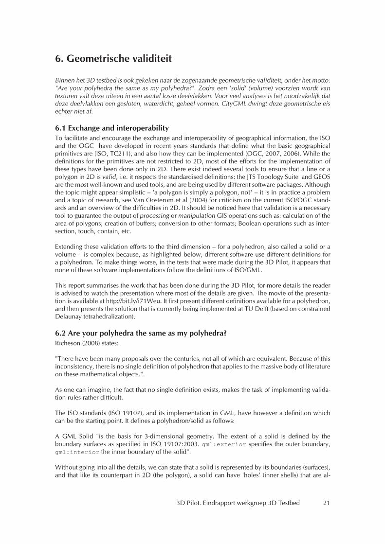
lowed to touch each others, or the outer boundary, but only under certain circumstances. To be con-sidered as a valid solid, a solid must fulfil several properties. The most important are:
1. It must be simple (no self-intersection of its boundary).2. It must be closed, or 'watertight'.3. Its interior must be connected.4. Its boundary surfaces must be properly oriented (normal pointing 'outwards').5. Its surfaces are not allowed to overlap each others.
Figure 14 shows eight different polyhedra, some of them valid, some not, with a brief explanation. It should be noticed that since a solid is formed of 2D primitives (embedded in 3D space), these also have to be valid. For instance, if a surface has a hole (an inner ring), than this ring is not allowed to overlap with the outer boundary of the surface.
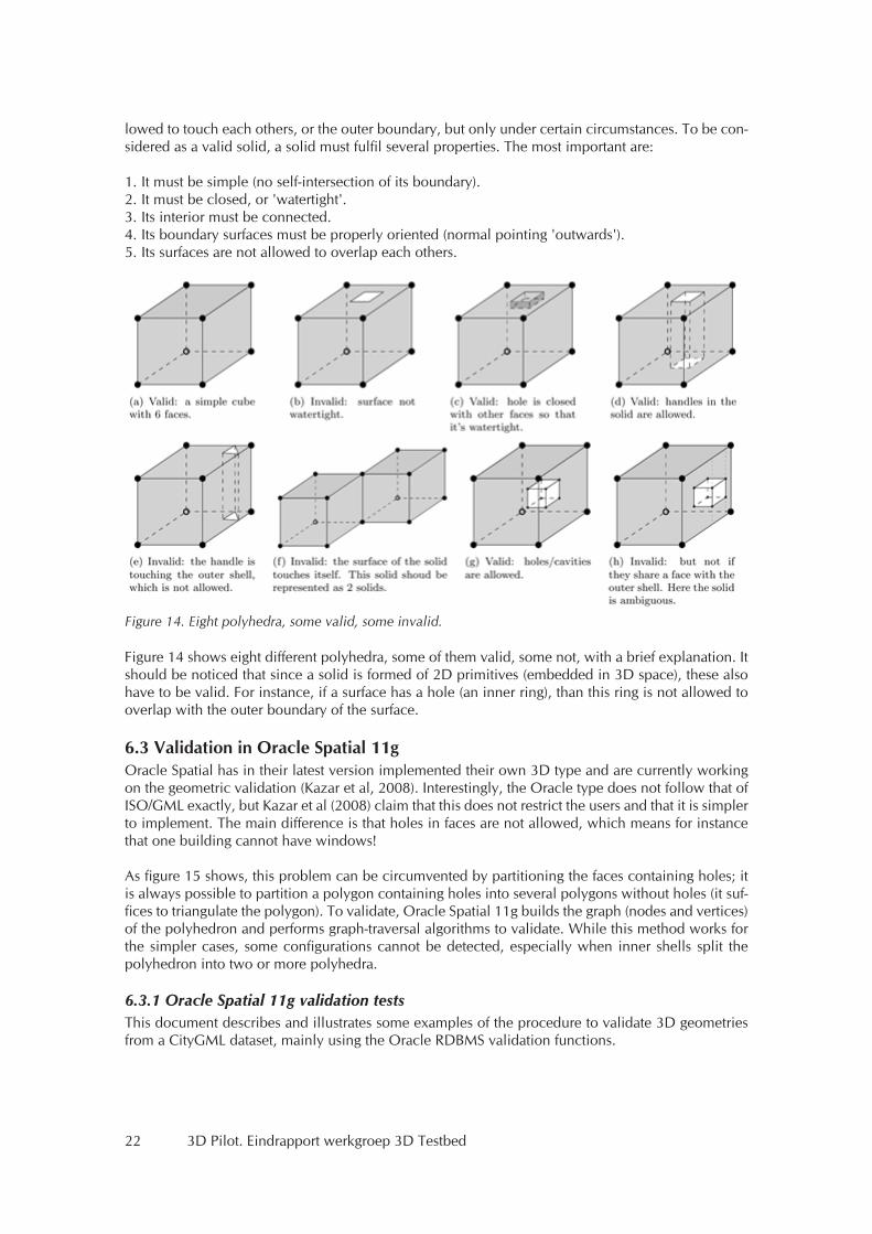
6.3 Validation in Oracle Spatial 11gOracle Spatial has in their latest version implemented their own 3D type and are currently working on the geometric validation (Kazar et al, 2008). Interestingly, the Oracle type does not follow that of ISO/GML exactly, but Kazar et al (2008) claim that this does not restrict the users and that it is simpler to implement. The main difference is that holes in faces are not allowed, which means for instance that one building cannot have windows!
As figure 15 shows, this problem can be circumvented by partitioning the faces containing holes; it is always possible to partition a polygon containing holes into several polygons without holes (it suf-fices to triangulate the polygon). To validate, Oracle Spatial 11g builds the graph (nodes and vertices) of the polyhedron and performs graph-traversal algorithms to validate. While this method works for the simpler cases, some configurations cannot be detected, especially when inner shells split the polyhedron into two or more polyhedra.
6.3.1 Oracle Spatial 11g validation testsThis document describes and illustrates some examples of the procedure to validate 3D geometries from a CityGML dataset, mainly using the Oracle RDBMS validation functions.
Figure 14. Eight polyhedra, some valid, some invalid.
3D Pilot. Eindrapport werkgroep 3D Testbed 23
The important steps of the procedure described in this document are:
– Take a CityGML file containing 3D solids as a starting point. – Use FME to load this data into an Oracle database. – Check the 3D geometries with the Oracle VALIDATE_GEOMETRY_WITH_CONTEXT () function.
The software used during the procedure is:
– FME Desktop Oracle Edition 2011 (including FME Data Inspector). – Oracle Database 11g Enterprise Edition Release 11.2.0.2.0
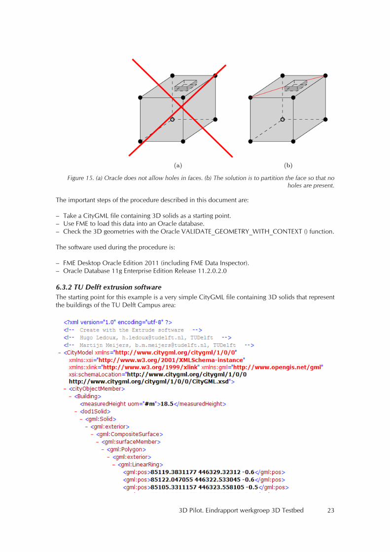
6.3.2 TU Delft extrusion softwareThe starting point for this example is a very simple CityGML file containing 3D solids that represent the buildings of the TU Delft Campus area:
Figure 15. (a) Oracle does not allow holes in faces. (b) The solution is to partition the face so that no holes are present.
24 3D Pilot. Eindrapport werkgroep 3D Testbed
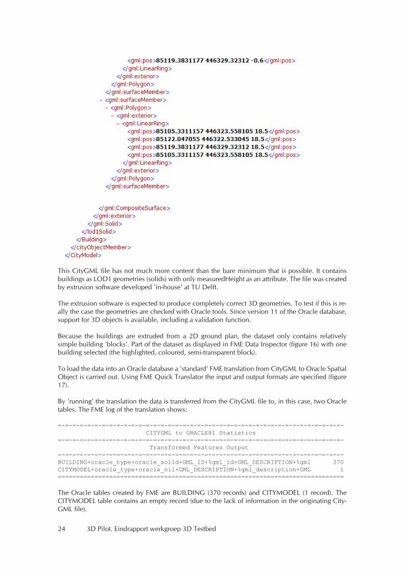
This CityGML file has not much more content than the bare minimum that is possible. It contains buildings as LOD1 geometries (solids) with only measuredHeight as an attribute. The file was created by extrusion software developed 'in-house' at TU Delft.
The extrusion software is expected to produce completely correct 3D geometries. To test if this is re-ally the case the geometries are checked with Oracle tools. Since version 11 of the Oracle database, support for 3D objects is available, including a validation function.
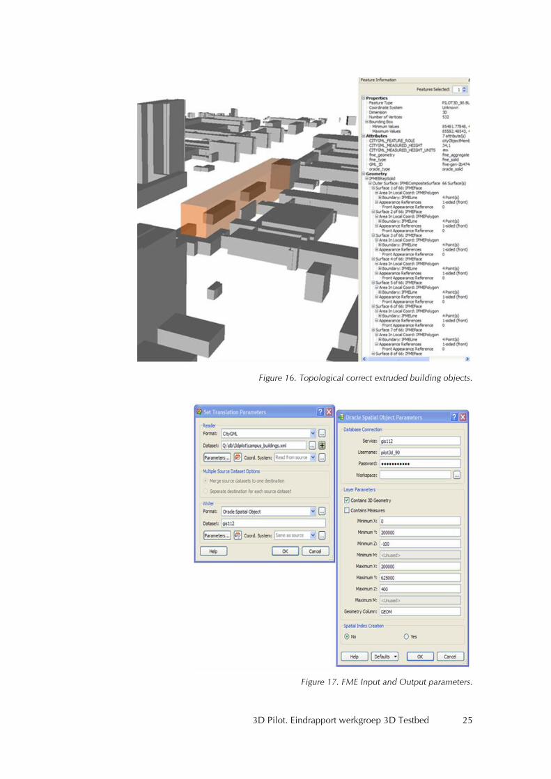
Because the buildings are extruded from a 2D ground plan, the dataset only contains relatively simple building 'blocks'. Part of the dataset as displayed in FME Data Inspector (figure 16) with one building selected (the highlighted, coloured, semi-transparent block).
To load the data into an Oracle database a 'standard' FME translation from CityGML to Oracle Spatial Object is carried out. Using FME Quick Translator the input and output formats are specified (figure 17).
By 'running' the translation the data is transferred from the CityGML file to, in this case, two Oracle tables. The FME log of the translation shows:
=-=-=-=-=-=-=-=-=-=-=-=-=-=-=-=-=-=-=-=-=-=-=-=-=-=-=-=-=-=-=-=-=-=-=-=-=-=-=- CITYGML to ORACLE8I Statistics=-=-=-=-=-=-=-=-=-=-=-=-=-=-=-=-=-=-=-=-=-=-=-=-=-=-=-=-=-=-=-=-=-=-=-=-=-=-=- Transformed Features Output=-=-=-=-=-=-=-=-=-=-=-=-=-=-=-=-=-=-=-=-=-=-=-=-=-=-=-=-=-=-=-=-=-=-=-=-=-=-=-BUILDING+oracle_type+oracle_solid+GML_ID+%gml_id+GML_DESCRIPTION+%gml 370CITYMODEL+oracle_type+oracle_nil+GML_DESCRIPTION+%gml_description+GML 1==============================================================================
The Oracle tables created by FME are BUILDING (370 records) and CITYMODEL (1 record). The CITYMODEL table contains an empty record (due to the lack of information in the originating City-GML file).
3D Pilot. Eindrapport werkgroep 3D Testbed 25
Figure 16. Topological correct extruded building objects.
Figure 17. FME Input and Output parameters.
26 3D Pilot. Eindrapport werkgroep 3D Testbed
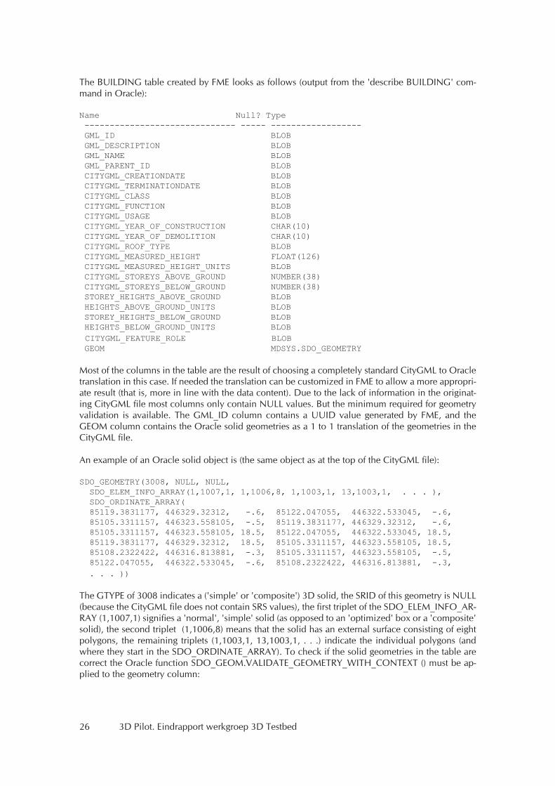
The BUILDING table created by FME looks as follows (output from the 'describe BUILDING' com-mand in Oracle):
Name Null? Type ------------------------------ ----- ------------------ GML_ID BLOB GML_DESCRIPTION BLOB GML_NAME BLOB GML_PARENT_ID BLOB CITYGML_CREATIONDATE BLOB CITYGML_TERMINATIONDATE BLOB CITYGML_CLASS BLOB CITYGML_FUNCTION BLOB CITYGML_USAGE BLOB CITYGML_YEAR_OF_CONSTRUCTION CHAR(10) CITYGML_YEAR_OF_DEMOLITION CHAR(10) CITYGML_ROOF_TYPE BLOB CITYGML_MEASURED_HEIGHT FLOAT(126) CITYGML_MEASURED_HEIGHT_UNITS BLOB CITYGML_STOREYS_ABOVE_GROUND NUMBER(38) CITYGML_STOREYS_BELOW_GROUND NUMBER(38) STOREY_HEIGHTS_ABOVE_GROUND BLOB HEIGHTS_ABOVE_GROUND_UNITS BLOB STOREY_HEIGHTS_BELOW_GROUND BLOB HEIGHTS_BELOW_GROUND_UNITS BLOB CITYGML_FEATURE_ROLE BLOB GEOM MDSYS.SDO_GEOMETRY
Most of the columns in the table are the result of choosing a completely standard CityGML to Oracle translation in this case. If needed the translation can be customized in FME to allow a more appropri-ate result (that is, more in line with the data content). Due to the lack of information in the originat-ing CityGML file most columns only contain NULL values. But the minimum required for geometry validation is available. The GML_ID column contains a UUID value generated by FME, and the GEOM column contains the Oracle solid geometries as a 1 to 1 translation of the geometries in the CityGML file.
An example of an Oracle solid object is (the same object as at the top of the CityGML file):
SDO_GEOMETRY(3008, NULL, NULL, SDO_ELEM_INFO_ARRAY(1,1007,1, 1,1006,8, 1,1003,1, 13,1003,1, . . . ), SDO_ORDINATE_ARRAY( 85119.3831177, 446329.32312, -.6, 85122.047055, 446322.533045, -.6, 85105.3311157, 446323.558105, -.5, 85119.3831177, 446329.32312, -.6, 85105.3311157, 446323.558105, 18.5, 85122.047055, 446322.533045, 18.5, 85119.3831177, 446329.32312, 18.5, 85105.3311157, 446323.558105, 18.5, 85108.2322422, 446316.813881, -.3, 85105.3311157, 446323.558105, -.5, 85122.047055, 446322.533045, -.6, 85108.2322422, 446316.813881, -.3, . . . ))
The GTYPE of 3008 indicates a ('simple' or 'composite') 3D solid, the SRID of this geometry is NULL (because the CityGML file does not contain SRS values), the first triplet of the SDO_ELEM_INFO_AR-RAY (1,1007,1) signifies a 'normal', 'simple' solid (as opposed to an 'optimized' box or a 'composite' solid), the second triplet (1,1006,8) means that the solid has an external surface consisting of eight polygons, the remaining triplets (1,1003,1, 13,1003,1, . . .) indicate the individual polygons (and where they start in the SDO_ORDINATE_ARRAY). To check if the solid geometries in the table are correct the Oracle function SDO_GEOM.VALIDATE_GEOMETRY_WITH_CONTEXT () must be ap-plied to the geometry column:
3D Pilot. Eindrapport werkgroep 3D Testbed 27
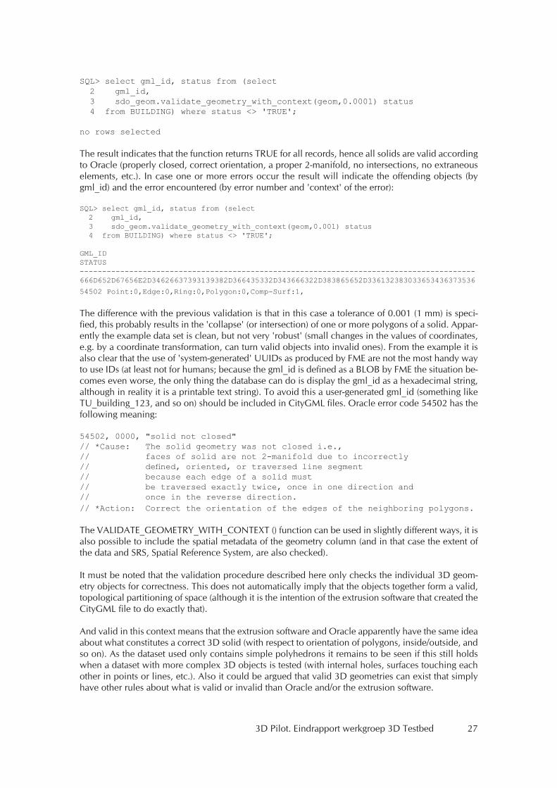
SQL> select gml_id, status from (select 2 gml_id, 3 sdo_geom.validate_geometry_with_context(geom,0.0001) status 4 from BUILDING) where status <> 'TRUE';
no rows selected
The result indicates that the function returns TRUE for all records, hence all solids are valid according to Oracle (properly closed, correct orientation, a proper 2-manifold, no intersections, no extraneous elements, etc.). In case one or more errors occur the result will indicate the offending objects (by gml_id) and the error encountered (by error number and 'context' of the error):
SQL> select gml_id, status from (select 2 gml_id, 3 sdo_geom.validate_geometry_with_context(geom,0.001) status 4 from BUILDING) where status <> 'TRUE';
GML_IDSTATUS----------------------------------------------------------------------------------------666D652D67656E2D34626637393139382D366435332D343666322D383865652D336132383033653436373536
54502 Point:0,Edge:0,Ring:0,Polygon:0,Comp-Surf:1,
The difference with the previous validation is that in this case a tolerance of 0.001 (1 mm) is speci-fied, this probably results in the 'collapse' (or intersection) of one or more polygons of a solid. Appar-ently the example data set is clean, but not very 'robust' (small changes in the values of coordinates, e.g. by a coordinate transformation, can turn valid objects into invalid ones). From the example it is also clear that the use of 'system-generated' UUIDs as produced by FME are not the most handy way to use IDs (at least not for humans; because the gml_id is defined as a BLOB by FME the situation be-comes even worse, the only thing the database can do is display the gml_id as a hexadecimal string, although in reality it is a printable text string). To avoid this a user-generated gml_id (something like TU_building_123, and so on) should be included in CityGML files. Oracle error code 54502 has the following meaning:
54502, 0000, "solid not closed"// *Cause: The solid geometry was not closed i.e., // faces of solid are not 2-manifold due to incorrectly// defined, oriented, or traversed line segment// because each edge of a solid must// be traversed exactly twice, once in one direction and// once in the reverse direction.// *Action: Correct the orientation of the edges of the neighboring polygons.
The VALIDATE_GEOMETRY_WITH_CONTEXT () function can be used in slightly different ways, it is also possible to include the spatial metadata of the geometry column (and in that case the extent of the data and SRS, Spatial Reference System, are also checked).
It must be noted that the validation procedure described here only checks the individual 3D geom-etry objects for correctness. This does not automatically imply that the objects together form a valid, topological partitioning of space (although it is the intention of the extrusion software that created the CityGML file to do exactly that).
And valid in this context means that the extrusion software and Oracle apparently have the same idea about what constitutes a correct 3D solid (with respect to orientation of polygons, inside/outside, and so on). As the dataset used only contains simple polyhedrons it remains to be seen if this still holds when a dataset with more complex 3D objects is tested (with internal holes, surfaces touching each other in points or lines, etc.). Also it could be argued that valid 3D geometries can exist that simply have other rules about what is valid or invalid than Oracle and/or the extrusion software.
28 3D Pilot. Eindrapport werkgroep 3D Testbed
6.3.3 ArcGIS 10In the latest version, ArcGIS offers validation rules. However these are still rather simple as only outer shells are considered: watertightness and self-intersection are verified, and holes are not allowed.
6.3.4 Bentley V8iBentley V8i relies on their Microstation data structure for the validation. That means that inner shells are not taken into consideration either, but holes in faces are permitted.
6.4 Validation with the Constrained Delaunay TetrahedralizationWe believe that instead of building a edge-based data structure to validate, a space-filling data struc-ture would give much better results. Nooruddin and Turk (2003) also tried space-filling methods, but used voxels (which could introduce errors depending on the resolution used). Our approach to geometric validation consists of buildings, the Constrained Delaunay Tetrahedralization (CDT) of the input polyhedron, and use the properties of the CDT to verify if it fulfils the definition of a valid polyhedron. It is also a space-filling data structure, but does not have the shortcomings of raster
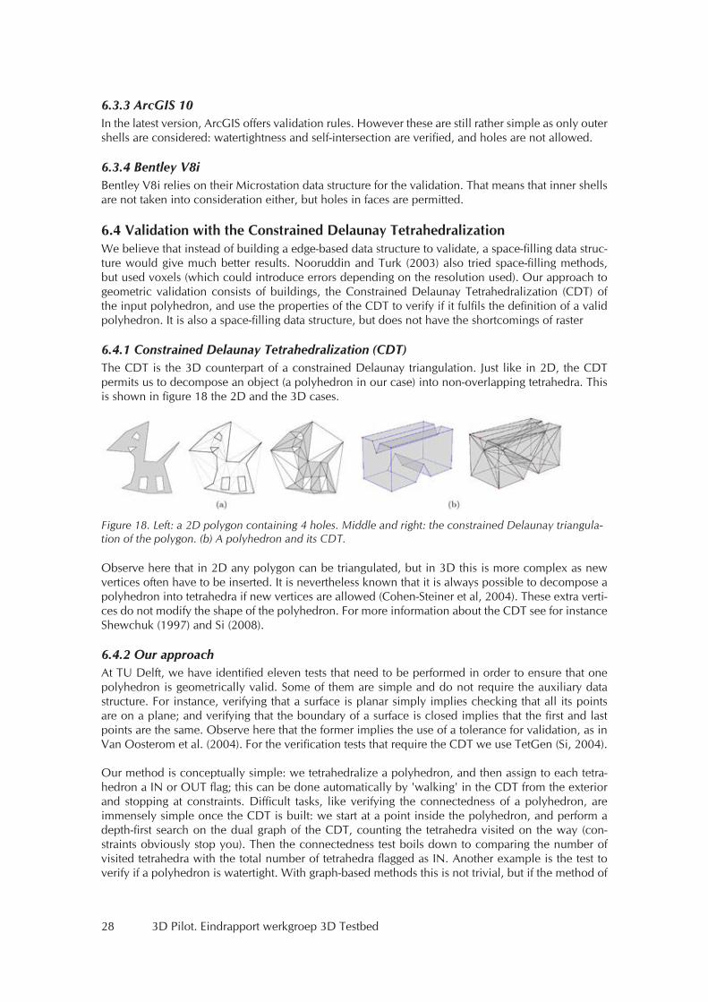
6.4.1 Constrained Delaunay Tetrahedralization (CDT)The CDT is the 3D counterpart of a constrained Delaunay triangulation. Just like in 2D, the CDT permits us to decompose an object (a polyhedron in our case) into non-overlapping tetrahedra. This is shown in figure 18 the 2D and the 3D cases.
Observe here that in 2D any polygon can be triangulated, but in 3D this is more complex as new vertices often have to be inserted. It is nevertheless known that it is always possible to decompose a polyhedron into tetrahedra if new vertices are allowed (Cohen-Steiner et al, 2004). These extra verti-ces do not modify the shape of the polyhedron. For more information about the CDT see for instance Shewchuk (1997) and Si (2008).
6.4.2 Our approachAt TU Delft, we have identified eleven tests that need to be performed in order to ensure that one polyhedron is geometrically valid. Some of them are simple and do not require the auxiliary data structure. For instance, verifying that a surface is planar simply implies checking that all its points are on a plane; and verifying that the boundary of a surface is closed implies that the first and last points are the same. Observe here that the former implies the use of a tolerance for validation, as in Van Oosterom et al. (2004). For the verification tests that require the CDT we use TetGen (Si, 2004).
Our method is conceptually simple: we tetrahedralize a polyhedron, and then assign to each tetra-hedron a IN or OUT flag; this can be done automatically by 'walking' in the CDT from the exterior and stopping at constraints. Difficult tasks, like verifying the connectedness of a polyhedron, are immensely simple once the CDT is built: we start at a point inside the polyhedron, and perform a depth-first search on the dual graph of the CDT, counting the tetrahedra visited on the way (con-straints obviously stop you). Then the connectedness test boils down to comparing the number of visited tetrahedra with the total number of tetrahedra flagged as IN. Another example is the test to verify if a polyhedron is watertight. With graph-based methods this is not trivial, but if the method of
Figure 18. Left: a 2D polygon containing 4 holes. Middle and right: the constrained Delaunay triangula-tion of the polygon. (b) A polyhedron and its CDT.

3D Pilot. Eindrapport werkgroep 3D Testbed 29
walking from the outside just described is used, then again the result is automatically found: all the tetrahedra are flagged as OUT.
6.4.3 SummaryValidating polyhedra is complex because there are different definitions, and because the processing of 3D geometries is difficult. Some software do have validation rules, but they use a simpler definition of a polyhedron, and do not consider inner shells and/or holes inside faces. That permits them to of-fer validation rules, but these are not ISO/GML compliant and can not be used to represent all cases.We are currently implementing the validation method with the CDT, and hope to report soon on the results. Our aim is also to offer (semi-)automatic repair functions, i.e. if a polyhedron is not valid the program would fix it automatically and return to the user a valid polyhedron.

30 3D Pilot. Eindrapport werkgroep 3D Testbed
3D Pilot. Eindrapport werkgroep 3D Testbed 31
7. Literatuur
Cohen-Steiner, C., E. Colin de Verdière and M. Yvinec, Conforming Delaunay triangulations in 3d. Computational Geometry – Theory and Applications, 28: 217-233, 2004.
ISO(TC211), ISO 19107:2003: Geographic information – Spatial schema. International Organization for Standardization, 2003.
Kazar, B.M., R. Kothuri, P. van Oosterom and S. Ravada, On valid and invalid three-dimensional geometries. In P. van Oosterom, S. Zlatanova, F. Penninga, and E. Fendel, editors, Advances in 3D Geoinformation Systems, Lectures Notes in Geoinformation and Cartography, chapter 2, pages 19–46. Springer Berlin Heidelberg, 2008.
Ledoux, H. and M. Meijers, Topologically consistent 3D city models obtained by extrusion. Internation-al Journal of Geographical Information Science, 25(4), 557-574, doi:10.1080/13658811003623277, 2011
Nooruddin F. and G. Tur,. Simplification and repair of polygonal models using volumetric tech-niques. IEEE Transactions on Visualization and Computer Graphics, 9(2):191-205, 2003.
OGC, OpenGIS implementation specification for geographic information – simple feature access. Open Geospatial Consortium inc., 2006. Document 06-103r3.
OGC, Geography markup language (GML) encoding standard. Open Geospatial Consortium inc., 2007. Document 07-036, version 3.2.1.
Richeson. D.S., Euler's Gem: The Polyhedron Formula and the Birth of Topology. Princeton Univer-sity Press, 2008.
Shewchuk, J.R., Delaunay Refinement Mesh Generation. PhD thesis, School of Computer Science, Carnegie Mellon University, Pittsburg, USA, 1997.
Si, H., Tetgen: A quality tetrahedral mesh generator and three-dimensional Delaunay triangulator. User's manual v1.3 9, WIAS, Berlin, Germany, 2004.
Si, H., Three Dimensional Boundary Conforming Delaunay Mesh Generation. PhD thesis, Berlin Institute of Technology, Berlin, Germany, 2008.
Van Oosterom, P. , W. Quak, and T. Tijssen, About invalid, valid and clean polygons. In P. F. Fisher, editor, Developments in Spatial Data Handling – 11th International Symposium on Spatial Data Handling, pages 1-16. Springer, 2004.