


Talen
Pages
Wettelijk

Documentatie Cartridge kleppen 2/2 - 3/2
De gegevens in deze documentatie zijn met de grootste zorg samengesteld, maar mogen geen reden zijn om ons aansprakelijk te stellen voor de gevolgen van fouten, die ondanks alle controles toch nog zouden kunnen zijn achtergebleven. Wij behouden ons het recht voor aanvullingen of wijzigingen aan te brengen zonder voorafgaande mededeling te doen. Uiteraard zijn wij niet beperkt tot dit assortiment, specials kunt u altijd bij ons aanvragen!
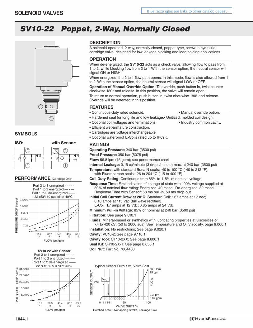
SV10-22 Poppet, 2-Way, Normally Closed
DESCRIPTIONA solenoid-operated, 2-way, normally closed, poppet-type, screw-in hydraulic cartridge valve, designed for low leakage blocking and load holding applications.
OPERATIONWhen de-energized, the SV10-22 acts as a check valve, allowing flow to pass from 1 to 2, while blocking flow from 2 to 1. With the sensor option, the neutral sensor will signal ON or HIGH.When energized, the 2 to 1 flow path opens. In this mode, flow is also allowed from 1 to 2. With the sensor option, the neutral sensor will signal LOW or OFF.Operation of Manual Override Option: To override, push button in, twist counter-clockwise 180° and release. In this position, the valve will remain open.To return to normal operation, push button in, twist clockwise 180° and release. Override will be detented in this position.
FEATURES• Continuous-duty rated solenoid. • Manual override option.• Hardened seat for long life and low leakage. • Unitized, molded coil design.• Optional coil voltages and terminations. • Industry common cavity.• Efficient wet-armature construction.• Cartridges are voltage interchangeable.• Optional waterproof E-Coils rated up to IP69K.
RATINGSOperating Pressure: 240 bar (3500 psi)Proof Pressure: 350 bar (5075 psi)Flow: 56.8 lpm (15 gpm); see performance chartInternal Leakage: 0.15 cc/minute (3 drops/minute) max. at 240 bar (3500 psi)Temperature: with standard Buna N seals: -40 to 100 °C (-40 to 212 °F);
with Fluorocarbon seals: -26 to 204 °C (-15 to 400 °F)Coil Duty Rating: Continuous from 85% to 115% of nominal voltageResponse Time: First indication of change of state with 100% voltage supplied at
80% of nominal flow rating: Energized: 40 msec.; De-energized: 32 msec. Response Time with Sensor: 68 ms pull-in, 50 ms drop-out
Initial Coil Current Draw at 20°C: Standard Coil: 1.67 amps at 12 Vdc; 0.18 amps at 115 Vac (full wave rectified). E-Coil: 1.7 amps at 12 Vdc; 0.85 amps at 24 Vdc
Minimum Pull-in Voltage: 85% of nominal at 240 bar (3500 psi)Filtration: See page 9.010.1Fluids: Mineral-based or synthetics with lubricating properties at viscosities of
7.4 to 420 cSt (50 to 2000 sus); See Temperature and Oil Viscosity, page 9.060.1Installation: No restrictions; See page 9.020.1Cavity: VC10-2; See page 9.110.1Cavity Tool: CT10-2XX; See page 8.600.1Seal Kit: SK10-2X-T; See page 8.650.1Coil Nut: Part No. 7004400
SYMBOLS
1.044.1
Port 2 to 1 energized - - - - -Port 1 to 2 energized — - —
Port 1 to 2 de-energized ——32 cSt/150 sus oil at 40°C
8.6/125
6.9/100
5.2/75
3.4/50
1.7/25
11.43
22.76
34.19
45.412
FLOW lpm/gpm
PR
ES
SU
RE
DR
OP
bar
/psi
56.815
PERFORMANCE (Cartridge Only)
SOLENOID VALVES
HYDRAFORCE.com®
ISO: with Sensor:
34.5/500
27.6/400
20.7/300
13.8/200
6.9/100
FLOW lpm/gpm
PR
ES
SU
RE
DR
OP
bar
/psi
SV10-22 with SensorPort 2 to 1 energized - - - - -Port 1 to 2 energized — - —
Port 1 to 2 de-energized ——32 cSt/150 sus oil at 40°C
15.94
30.38
45.412
60.616
75.720 VALVE SHIFT %
FLO
W
Vcc
SE
NS
OR
OU
TP
UT
Typical Sensor Output vs. Valve Shift
0
0.3 lpm0.07 gpm
56.8 lpm15 gpm
11 14 50 100
Hatched Area: Overlapping Stroke, Leakage Flow
VOUT
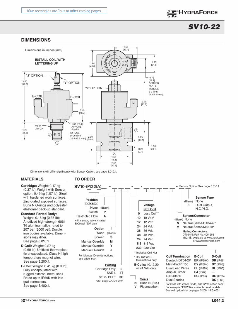
DIMENSIONS
SV10-22
1.044.2
3.50[89.0]
1.55[39.4]
2.90[73.7]
1.84[46.6]
0.75[19.1]ACROSSFLATS
3.40[86.4]
1.25[31.8]
D-COILE-COIL
"J" OPTION
"Y" OPTION
1.00 [25.4]ACROSSFLATS
"M" OPTION
INSTALL COIL WITHLETTERING UP
1.63[41.3]2.00
2.00[50.8]
0.28[7.1]
0.75[19.1]
1.50[38.1]
1
2
7/8-14UNF-2A1.25
[31.8] TORQUE24-26 lbf•ft[32.5-35.3 N•m]
TORQUE5-7 lbf•ft[6.8-9.5 N•m]
[50.8]
Dimensions in inches [mm]
®HYDRAFORCE
HYDRAFORCE.com®
Dimensions will differ significantly with Sensor Option; see page 3.010.1.
TO ORDER
SV10-(P)22(A)__ - __ __ __ - __ - __ __ __ __ __ - __ __
Option None (Blank)
Screen S Manual Override M Manual Override Y Manual Override J
For Manual Override optionssee page 1.001.1
Cartridge: Weight: 0.17 kg (0.37 lb); Weight with Sensor option: 0.49 kg (1.07 lb); Steel with hardened work surfaces. Zinc-plated exposed surfaces. Buna N O-rings and polyester elastomer back-up standard.
Standard Ported Body: Weight: 0.16 kg (0.35 lb); Anodized high-strength 6061 T6 aluminum alloy, rated to 207 bar (3000 psi). Ductile iron bodies available; Dimen-sions may differ. See page 8.010.1.
D-Coil: Weight: 0.27 kg (0.60 lb); Unitized thermoplas-tic encapsulated, Class H high temperature magnet wire. See page 3.200.1.
E-Coil: Weight: 0.41 kg (0.9 lb); Fully encapsulated with rugged external metal shell. Rated up to IP69K with inte-gral connectors. See page 3.400.1.
Voltage Std. Coil 0 Less Coil** 10 10 Vdc†
12 12 Vdc 24 24 Vdc 36 36 Vdc 48 48 Vdc 24 24 Vac 115 115 Vac 230 230 Vac
**Includes Coil Nut† DS, DW or DL
terminations only
E-Coils: 10,12,20 or 24 Vdc only.
MATERIALS
For Coils with Zener Diode, add “/Z” to option code. For example: “ER/Z”. Not available on all models. See coil option info. on pages 3.200.1 & 3.400.1
Coil Termination E-Coil D-CoilDeutsch DT04-2P ER (IP69K) DR (IP65)Metri-Pack® 150 EY (IP69K) DY (IP65)Dual Lead Wires EL (IP69K) DL (IP65)Amp Jr. Timer EJ (IP67) —DIN 43650 EG (IP65) DG (IP65)Dual Spades — DS (IP65) Seals
N Buna N (Std.) V Fluorocarbon
Sensor Option: See page 3.010.1
Sensor/Connector (Blank) None N Neutral Sense/DT04-4P M Neutral Sense/M12-4P Mating Connectors: DT06-4S: Part No. 4001953 M12-4S: available at www.turck.com or www.binder-usa.com
Position Indicator None (Blank)
Switch P Restricted Flow A
Sensor Type (Blank) None 3 Dual Output, N.C./N.O.
with sensor, valve is rated 3000 psi (207 bar)
Porting Cartridge Only 0 SAE 8 8T 3/8 in. BSP* 3B
*BSP Body; U.K. Mfr. Only

SV10-23 Poppet, 2-Way, Normally Open
DESCRIPTIONA solenoid-operated, two-way, poppet-type, normally open, screw-in, hydraulic cartridge valve.
OPERATIONWhen de-energized, the SV10-23 allows bidirectional flow from 2 to 1. With the sensor option, the neutral sensor will signal OFF or LOW.When energized, the valve’s poppet closes to block flow from 2 to 1. In this mode, the cartridge allows free reverse flow from 1 to 2 after overcoming the solenoid force (requires 3.4 to 10.3 bar / 50 to 150 psi). With the sensor option, the neutral sensor will signal ON or HIGH.Operation of Manual Override Option: To override, push and hold override button.
FEATURES• Continuous-duty rated solenoid. • Manual override option.• Hardened seat for long life and low leakage. • Unitized, molded coil design.• Optional coil voltages and terminations. • Industry common cavity.• Efficient wet-armature construction.• Cartridges are voltage interchangeable.• Optional waterproof E-Coils rated up to IP69K.
RATINGSOperating Pressure: 207 bar (3000 psi)Proof Pressure: 345 bar (5000 psi)Flow: 68.1 lpm (18 gpm); see performance chartInternal Leakage: 0.15 cc/minute (3 drops/minute) max. at 207 bar (3000 psi)Temperature: with standard Buna N seals: -40 to 100°C (-40° to 212°F);
with Fluorocarbon seals: -26 to 204°C (-15°F to 400°F)Coil Duty Rating: Continuous from 85% to 115% of nominal voltageResponse Time: First indication of change of state with 100% voltage supplied at
80% of nominal flow rating: Energized: 80 msec.; De-energized: 30 msec. Response Time with Sensor: 158 ms pull-in, 57 ms drop-out
Initial Coil Current Draw at 20°C: Standard Coil: 1.67 amps at 12 VDC; 0.18 amps at 115 VAC (full wave rectified). E-Coil: 1.7 amps at 12 VDC; 0.85 amps at 24 VDC
Minimum Pull-in Voltage: 85% of nominal at 207 bar (3000 psi)Filtration: See page 9.010.1Fluids: Mineral-based or synthetics with lubricating properties at viscosities of
7.4 to 420 cSt (50 to 2000 sus); See Temperature and Oil Viscosity, page 9.060.1Installation: No restrictions; See page 9.020.1Cavity: VC10-2; See page 9.110.1Cavity Tool: CT10-2XX; See page 8.600.1Seal Kit: SK10-2X-T; See page 8.650.1Coil Nut: Part No. 7004420
ISO: with Sensor:
PERFORMANCE (Cartridge Only)
SYMBOLS
1.053.1
8.6/125
6.9/100
5.2/75
3.4/50
1.7/25
11.43
22.76
34.19
56.815
FLOW lpm/gpm
PR
ES
SU
RE
DR
OP
bar
/psi
45.412
68.118
Port 2 to 1 De-energized ——Port 1 to 2 Energized - - - -32 cSt/150 sus oil at 40°C
SOLENOID VALVES
HYDRAFORCE.com®
SV10-23 with SensorPort 2 to 1 Energized - - - - -Port 1 to 2 Energized — - —
Port 1 to 2 De-energized ——32 cSt/150 sus oil at 40°C
34.5/500
27.6/400
20.7/300
13.8/200
6.9/100
FLOW lpm/gpm
PR
ES
SU
RE
DR
OP
bar
/psi
15.94
30.38
45.412
60.616
75.720 VALVE SHIFT %
FLO
W
Vcc
SE
NS
OR
OU
TP
UT
Typical Sensor Output vs. Valve Shift
0
0.3 lpm0.07 gpm
56.8 lpm15 gpm
70 7450 100
VOUT
Hatched Area: Overlapping Stroke, Leakage Flow
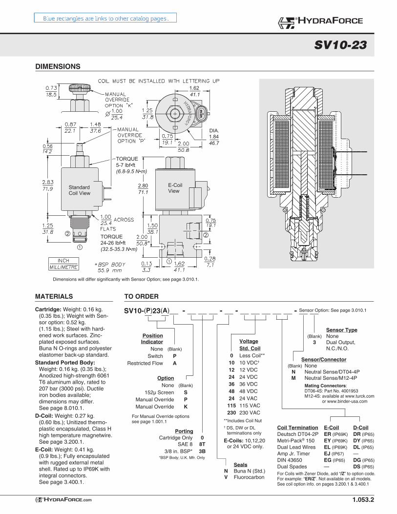
SV10-23
DIMENSIONS
1.053.2
1.6241.1
1.84DIA.
46.7
E-CoilView
StandardCoil View
2.8071.1
TORQUE24-26 lbf•ft(32.5-35.3 N•m)
TORQUE5-7 lbf•ft(6.8-9.5 N•m)
®HYDRAFORCE
HYDRAFORCE.com®
Dimensions will differ significantly with Sensor Option; see page 3.010.1.
TO ORDER
SV10-(P)23(A)__ - __ __ __ - __ - __ __ __ __ __ - __ __
Option None (Blank)
152µ Screen S Manual Override P Manual Override K
For Manual Override optionssee page 1.001.1
Cartridge: Weight: 0.16 kg. (0.35 lbs.); Weight with Sen-sor option: 0.52 kg. (1.15 lbs.); Steel with hard-ened work surfaces. Zinc-plated exposed surfaces. Buna N O-rings and polyester elastomer back-up standard.
Standard Ported Body: Weight: 0.16 kg. (0.35 lbs.); Anodized high-strength 6061 T6 aluminum alloy, rated to 207 bar (3000 psi). Ductile iron bodies available; dimensions may differ. See page 8.010.1.
D-Coil: Weight: 0.27 kg. (0.60 lbs.); Unitized thermo-plastic encapsulated, Class H high temperature magnetwire. See page 3.200.1.
E-Coil: Weight: 0.41 kg. (0.9 lbs.); Fully encapsulated with rugged external metal shell. Rated up to IP69K with integral connectors. See page 3.400.1.
Voltage Std. Coil 0 Less Coil** 10 10 VDC†
12 12 VDC 24 24 VDC 36 36 VDC 48 48 VDC 24 24 VAC 115 115 VAC 230 230 VAC
**Includes Coil Nut† DS, DW or DL
terminations only
E-Coils: 10,12,20 or 24 VDC only.
MATERIALS
For Coils with Zener Diode, add “/Z” to option code. For example: “ER/Z”. Not available on all models. See coil option info. on pages 3.200.1 & 3.400.1
Coil Termination E-Coil D-CoilDeutsch DT04-2P ER (IP69K) DR (IP65)Metri-Pack® 150 EY (IP69K) DY (IP65)Dual Lead Wires EL (IP69K) DL (IP65)Amp Jr. Timer EJ (IP67) —DIN 43650 EG (IP65) DG (IP65)Dual Spades — DS (IP65) Seals
N Buna N (Std.) V Fluorocarbon
Sensor Option: See page 3.010.1
Sensor/Connector (Blank) None N Neutral Sense/DT04-4P M Neutral Sense/M12-4P Mating Connectors: DT06-4S: Part No. 4001953 M12-4S: available at www.turck.com or www.binder-usa.com
Position Indicator None (Blank)
Switch P Restricted Flow A
Sensor Type (Blank) None 3 Dual Output, N.C./N.O.
Porting Cartridge Only 0 SAE 8 8T 3/8 in. BSP* 3B
*BSP Body; U.K. Mfr. Only
USASI/ISO:
SYMBOLS
1.092.1
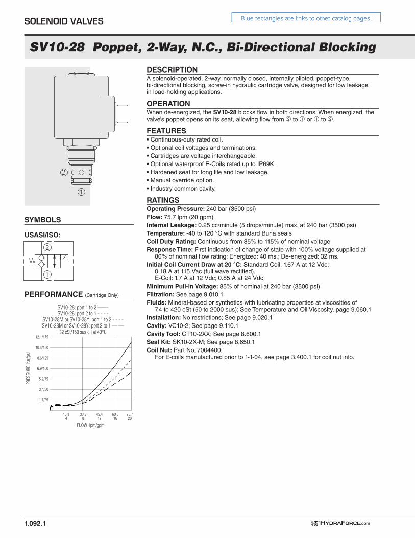
SV10-28 Poppet, 2-Way, N.C., Bi-Directional Blocking
1
2
3.4/50
5.2/75
6.9/100
8.6/125
10.3/150
12.1/175
1.7/25
15.14
30.38
45.412
60.616
FLOW lpm/gpm
PRES
SURE
bar
/psi
SV10-28: port 1 to 2 ——SV10-28: port 2 to 1 - - - -
SV10-28M or SV10-28Y: port 1 to 2 - - - -SV10-28M or SV10-28Y: port 2 to 1 — —
32 cSt/150 sus oil at 40°C
75.720
DESCRIPTIONA solenoid-operated, 2-way, normally closed, internally piloted, poppet-type, bi-directional blocking, screw-in hydraulic cartridge valve, designed for low leakage in load-holding applications.
OPERATIONWhen de-energized, the SV10-28 blocks flow in both directions. When energized, the valve’s poppet opens on its seat, allowing flow from ➁ to ➀ or ➀ to ➁.
FEATURES• Continuous-duty rated coil.• Optional coil voltages and terminations.• Cartridges are voltage interchangeable.• Optional waterproof E-Coils rated up to IP69K.• Hardened seat for long life and low leakage.• Manual override option.• Industry common cavity.
RATINGSOperating Pressure: 240 bar (3500 psi)Flow: 75.7 lpm (20 gpm)Internal Leakage: 0.25 cc/minute (5 drops/minute) max. at 240 bar (3500 psi)Temperature: -40 to 120 °C with standard Buna sealsCoil Duty Rating: Continuous from 85% to 115% of nominal voltageResponse Time: First indication of change of state with 100% voltage supplied at
80% of nominal flow rating: Energized: 40 ms.; De-energized: 32 ms.Initial Coil Current Draw at 20 °C: Standard Coil: 1.67 A at 12 Vdc;
0.18 A at 115 Vac (full wave rectified). E-Coil: 1.7 A at 12 Vdc; 0.85 A at 24 Vdc
Minimum Pull-in Voltage: 85% of nominal at 240 bar (3500 psi)Filtration: See page 9.010.1 Fluids: Mineral-based or synthetics with lubricating properties at viscosities of
7.4 to 420 cSt (50 to 2000 sus); See Temperature and Oil Viscosity, page 9.060.1Installation: No restrictions; See page 9.020.1Cavity: VC10-2; See page 9.110.1Cavity Tool: CT10-2XX; See page 8.600.1Seal Kit: SK10-2X-M; See page 8.650.1Coil Nut: Part No. 7004400;
For E-coils manufactured prior to 1-1-04, see page 3.400.1 for coil nut info.
PERFORMANCE (Cartridge Only)
SOLENOID VALVES
HYDRAFORCE.com®
SV10-28
DIMENSIONS
1.092.2
1.6241.1
1.84DIA.
46.7
2.98
"M"ManualOverride
75.7
E-CoilView
StandardCoil View
TORQUE5–7 ft-lb
6.8–9.5 Nm
TORQUE24–26 ft-lb32.5–35.3 Nm
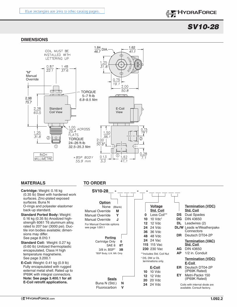
TO ORDER
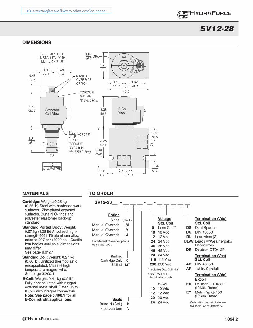
Cartridge: Weight: 0.16 kg (0.35 lb) Steel with hardened work surfaces. Zinc-plated exposed surfaces. Buna N O-rings and polyester elastomer back-up standard.
Standard Ported Body: Weight: 0.16 kg (0.35 lb) Anodized high-strength 6061 T6 aluminum alloy, rated to 207 bar (3000 psi). Duc-tile iron bodies available; dimen-sions may differ. See page 8.010.1
Standard Coil: Weight: 0.27 kg (0.60 lb) Unitized thermoplastic encapsulated, Class H high temperature magnetwire. See page 3.200.1
E-Coil: Weight: 0.41 kg (0.9 lb) Fully encapsulated with rugged external metal shell. Rated up to IP69K with integral connectors. Note: See page 3.400.1 for all E-Coil retrofit applications.
SV10-28__ - __ __ __ - __ - __ __ __ __ __
Seals Buna N (Std.) N Fluorocarbon V
Termination (VDC) Std. Coil DS Dual Spades DG DIN 43650 DL Leadwires (2) DL/W Leads w/Weatherpak®
Connectors DR Deutsch DT04-2P
Termination (VAC) Std. Coil AG DIN 43650 AP 1/2 in. Conduit
Termination (VDC) E-Coil ER Deutsch DT04-2P (IP69K Rated) EY Metri-Pack® 150 (IP69K Rated)
Coils with internal diode are available. Consult factory.
E-Coil 10 10 Vdc 12 12 Vdc 20 20 Vdc 24 24 Vdc
Voltage Std. Coil 0 Less Coil** 10 10 Vdc†
12 12 Vdc 24 24 Vdc 36 36 Vdc 48 48 Vdc 24 24 Vac 115 115 Vac 230 230 Vac**Includes Std. Coil Nut† DS, DW or DL
terminations only.
MATERIALS
®HYDRAFORCE
HYDRAFORCE.com®
For Manual Override optionssee page 1.001.1
Option None (Blank)
Manual Override M Manual Override Y Manual Override J
Porting Cartridge Only 0 SAE 8 8T 3/8 in. BSP* 3B
*BSP Body; U.K. Mfr. Only
ISO SYMBOL
1.098.1
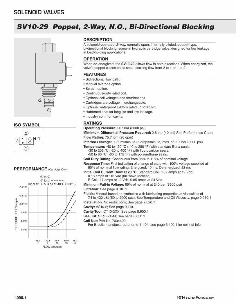
SV10-29 Poppet, 2-Way, N.O., Bi-Directional Blocking
DESCRIPTIONA solenoid-operated, 2-way, normally open, internally piloted, poppet-type, bi-directional blocking, screw-in hydraulic cartridge valve, designed for low leakage in load-holding applications.
OPERATIONWhen de-energized, the SV10-29 allows flow in both directions. When energized, the valve’s poppet closes on its seat, blocking flow from 2 to 1 or 1 to 2.
FEATURES• Bidirectional flow path.
• Manual override option.
• Screen option.
• Continuous-duty rated coil.
• Optional coil voltages and terminations.
• Cartridges are voltage interchangeable.
• Optional waterproof E-Coils rated up to IP69K.
• Hardened seat for long life and low leakage.
• Industry common cavity.
RATINGSOperating Pressure: 207 bar (3000 psi)
Mimimum Differential Pressure Required: 2.8 bar (40 psi) See Performance Chart.
Flow Rating: 75.7 lpm (20 gpm)
Internal Leakage: 0.25 ml/minute (5 drops/minute) max. at 207 bar (3000 psi)
Temperature: -40 to 120 °C (-40 to 250 °F) with standard Buna seals;-30 to 205 °C (-20 to 400 °F) with fluorocarbon seals;-50 to 80 °C (-60 to 175 °F) with polyurethane seals.
Coil Duty Rating: Continuous from 85% to 115% of nominal voltage
Response Time: First indication of change of state with 100% voltage supplied at 80% of nominal flow rating: Energized: 40 ms; De-energized: 32 ms
Initial Coil Current Draw at 20 °C: Standard Coil: 1.67 amps at 12 Vdc; 0.18 amps at 115 Vac (full wave rectified). E-Coil: 1.7 amps at 12 Vdc; 0.85 amps at 24 Vdc
Minimum Pull-in Voltage: 85% of nominal at 240 bar (3500 psi)
Filtration: See page 9.010.1
Fluids: Mineral-based or synthetics with lubricating properties at viscosities of 7.4 to 420 cSt (50 to 2000 sus); See Temperature and Oil Viscosity, page 9.060.1
Installation: No restrictions; See page 9.020.1
Cavity: VC10-2; See page 9.110.1
Cavity Tool: CT10-2XX; See page 8.600.1
Seal Kit: SK10-2X-M; See page 8.650.1
Coil Nut: Part No. 7004400; For E-coils manufactured prior to 1-1-04, see page 3.400.1 for coil nut info.
PERFORMANCE (Cartridge Only)
SOLENOID VALVES
HYDRAFORCE.com®
1
2
6.2/90
8.3/120
10.3/150
12.4/180
4.1/60
2.1/30PR
ES
SU
RE
DR
OP
bar/
psi
➀ to ➁ ————➁ to ➀ – – – – –
32 cSt/150 sus oil at 40 C (104 F)
15.14
30.38
45.412
60.616
FLOW lpm/gpm
75.720

Option
None (Blank)
Manual Override without knob P Manual Override with knob K
SV10-29
DIMENSIONS
1.098.2
TO ORDER
Cartridge: Weight: 0.16 kg (0.35 lb) Steel with hardened work surfac-es. Zinc-plated exposed surfaces. Buna N O-rings and polyester elastomer back-up standard.
Standard Ported Body: Weight: 0.16 kg (0.35 lb) Anodized high-strength aluminum alloy, rated to 207 bar (3000 psi). Ductile iron bodies available; dimensions may differ. See page 8.010.1
Standard Coil: Weight: 0.27 kg (0.60 lb) Unitized thermoplastic encapsulated, Class H high tem-perature magnet wire. See page 3.200.1
E-Coil: Weight: 0.41 kg (0.9 lb) Fully encapsulated with rugged external metal shell. Rated up to IP69K with integral connectors. Note: See page 3.400.1 for all E-Coil retrofit applications.
SV10-29__ __ - __ __ __ - __ - __ __ __ __ __
Seals
Buna N (Std.) N
Fluorocarbon V
Polyurethane P
Termination (VDC) Std. Coil
DS Dual Spades
DG DIN 43650
DL Leadwires (2)
DL/W Leads w/Weatherpak®
Connectors
DR Deutsch DT04-2P
Termination (VAC) Std. Coil
AG DIN 43650
AP 1/2 in. Conduit
Termination (VDC)
E-Coil
ER Deutsch DT04-2P (IP69K Rated)
EY Metri-Pack® 150 (IP69K Rated)
Coils with internal diode are available. Consult factory.
E-Coil
10 10 Vdc
12 12 Vdc
20 20 Vdc
24 24 Vdc
Voltage
Std. Coil
0 Less Coil**
10 10 Vdc†
12 12 Vdc
24 24 Vdc
36 36 Vdc
48 48 Vdc
24 24 Vac
115 115 Vac
230 230 Vac
**Includes Std. Coil Nut
† DS, DW or DL terminations only.
MATERIALS
®HYDRAFORCE
HYDRAFORCE.com®
For Manual Override options see page 1.001.1
1.62
41.1
1.84DIA.
46.7
E-CoilView
StandardCoil View
2.80
71.1
5-7 lb-ft(6.8-9.6 Nm)
24-26 lb-ft(32.5-35.3 Nm)
Screen Option
No Screen (Blank)
Screen S
Porting
Cartridge Only 0
SAE 8 8T
3/8 in. BSP* 3B*BSP Body; U.K. Mfr. Only
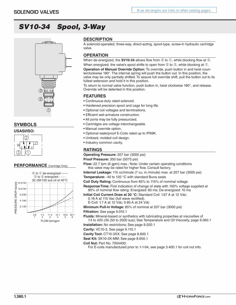
SV10-34 Spool, 3-Way
USASI/ISO:
1.380.1
PR
ES
SU
RE
DR
OP
bar
/psi 10.3/150
8.3/120
6.2/90
4.1/60
2.1/30
7.52
15.14
22.76
FLOW lpm/gpm
� to � de-energized ——� to � energized - - - -
32 cSt/150 sus oil at 40°C
3.81
11.43
18.95
DESCRIPTIONA solenoid-operated, three-way, direct-acting, spool-type, screw-in hydraulic cartridge valve.
OPERATIONWhen de-energized, the SV10-34 allows flow from ➁ to ➀, while blocking flow at ➂.When energized, the valve’s spool shifts to open from ➁ to ➂, while blocking at ➀.Operation of Manual Override Option: To override, push button in and twist coun-terclockwise 180°. The internal spring will push the button out. In this position, the valve may be only partially shifted. To assure full override shift, pull the button out to its fullest extension and hold it in this position.To return to normal valve function, push button in, twist clockwise 180°, and release. Override will be detented in this position.
FEATURES• Continuous-duty rated solenoid.• Hardened precision spool and cage for long life.• Optional coil voltages and terminations.• Efficient wet-armature construction.• All ports may be fully pressurized.• Cartridges are voltage interchangeable.• Manual override option.• Optional waterproof E-Coils rated up to IP69K.• Unitized, molded coil design.• Industry common cavity.
RATINGSOperating Pressure: 207 bar (3000 psi)Proof Pressure: 350 bar (5075 psi)Flow: 22.7 lpm (6 gpm) max.; Note: Under certain operating conditions
this valve may be rated for higher flow. Consult factory.Internal Leakage: 115 cc/minute (7 cu. in./minute) max. at 207 bar (3000 psi)Temperature: -40 to 120 °C with standard Buna sealsCoil Duty Rating: Continuous from 85% to 115% of nominal voltageResponse Time: First indication of change of state with 100% voltage supplied at
80% of nominal flow rating: Energized: 60 ms; De-energized: 10 msInitial Coil Current Draw at 20 °C: Standard Coil: 1.67 A at 12 Vdc;
0.18 A at 115 Vac (full wave rectified). E-Coil: 1.7 A at 12 Vdc; 0.85 A at 24 Vdc
Minimum Pull-in Voltage: 85% of nominal at 207 bar (3000 psi)Filtration: See page 9.010.1Fluids: Mineral-based or synthetics with lubricating properties at viscosities of
7.4 to 420 cSt (50 to 2000 sus); See Temperature and Oil Viscosity, page 9.060.1Installation: No restrictions; See page 9.020.1Cavity: VC10-3, See page 9.110.1Cavity Tool: CT10-3XX; See page 8.600.1Seal Kit: SK10-3X-MM; See page 8.650.1Coil Nut: Part No. 7004400;
For E-coils manufactured prior to 1-1-04, see page 3.400.1 for coil nut info.
SOLENOID VALVES
HYDRAFORCE.com®
SYMBOLS
PERFORMANCE (Cartridge Only)
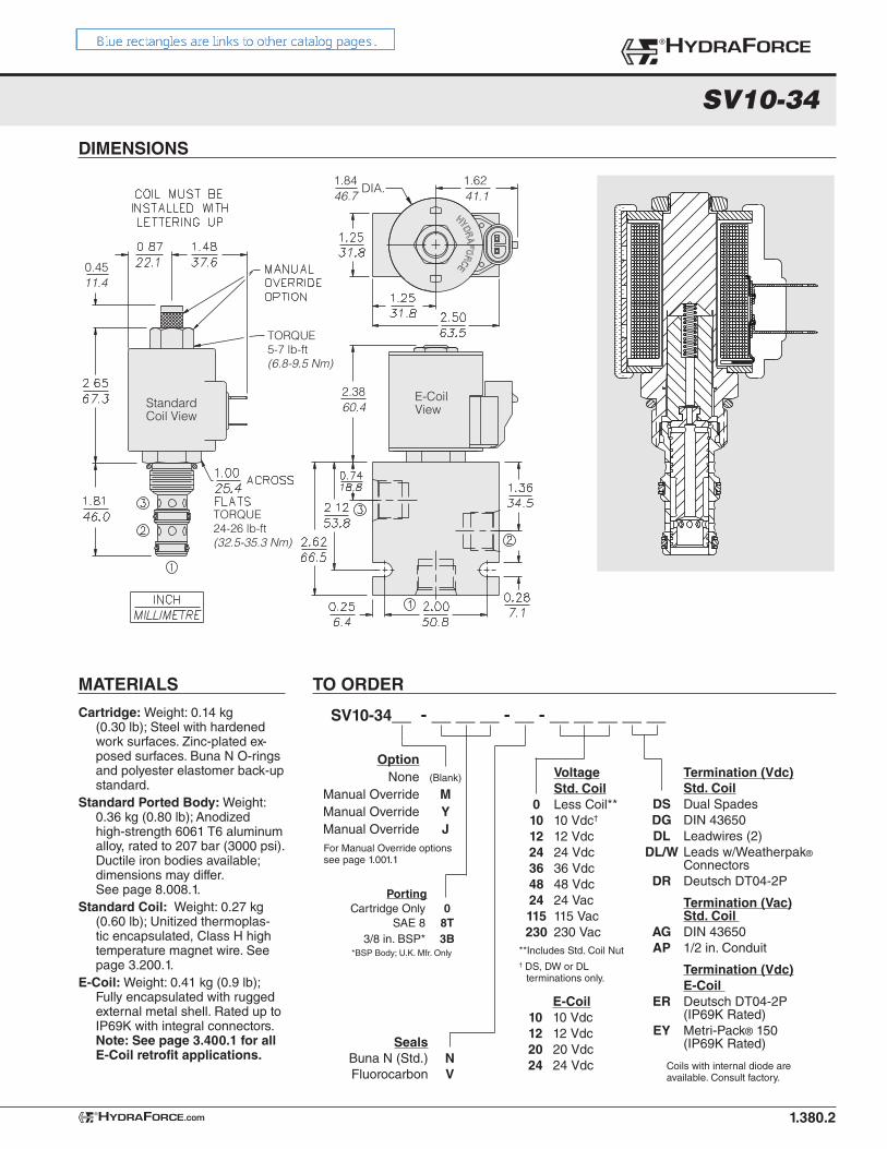
DIMENSIONS
SV10-34
1.380.2
1.6241.1
1.84DIA.
46.7
E-CoilView
2.3860.4Standard
Coil View
0.4511.4
TORQUE24-26 lb-ft(32.5-35.3 Nm)
TORQUE5-7 lb-ft(6.8-9.5 Nm)
®HYDRAFORCE
HYDRAFORCE.com®
TO ORDER
SV10-34__ - __ __ __ - __ - __ __ __ __ __
For Manual Override optionssee page 1.001.1
Cartridge: Weight: 0.14 kg (0.30 lb); Steel with hardened work surfaces. Zinc-plated ex-posed surfaces. Buna N O-rings and polyester elastomer back-up standard.
Standard Ported Body: Weight: 0.36 kg (0.80 lb); Anodized high-strength 6061 T6 aluminum alloy, rated to 207 bar (3000 psi). Ductile iron bodies available; dimensions may differ. See page 8.008.1.
Standard Coil: Weight: 0.27 kg (0.60 lb); Unitized thermoplas-tic encapsulated, Class H high temperature magnet wire. See page 3.200.1.
E-Coil: Weight: 0.41 kg (0.9 lb); Fully encapsulated with rugged external metal shell. Rated up to IP69K with integral connectors. Note: See page 3.400.1 for all E-Coil retrofit applications.
Seals Buna N (Std.) N Fluorocarbon V
Termination (Vdc) Std. Coil DS Dual Spades DG DIN 43650 DL Leadwires (2) DL/W Leads w/Weatherpak®
Connectors DR Deutsch DT04-2P
Termination (Vac) Std. Coil AG DIN 43650 AP 1/2 in. Conduit
Termination (Vdc) E-Coil ER Deutsch DT04-2P (IP69K Rated) EY Metri-Pack® 150 (IP69K Rated)
Coils with internal diode are available. Consult factory.
E-Coil 10 10 Vdc 12 12 Vdc 20 20 Vdc 24 24 Vdc
Voltage Std. Coil 0 Less Coil** 10 10 Vdc†
12 12 Vdc 24 24 Vdc 36 36 Vdc 48 48 Vdc 24 24 Vac 115 115 Vac 230 230 Vac**Includes Std. Coil Nut† DS, DW or DL
terminations only.
MATERIALS
Option None (Blank)
Manual Override M Manual Override Y Manual Override J
Porting Cartridge Only 0 SAE 8 8T 3/8 in. BSP* 3B
*BSP Body; U.K. Mfr. Only
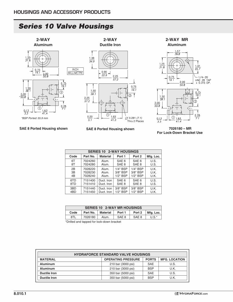
SERIES 10 2-WAY HOUSINGSCode
6T 8T
2B3B4B
6TD8TD
3BD4BD
Part No.
70242607024280
702822070282307028240
71514007151410
71514407151450
Material
Alum.Alum.
Alum.Alum.Alum.
Duct. IronDuct. Iron
Duct. IronDuct. Iron
Port 1
SAE 6SAE 8
1/4" BSP3/8" BSP1/2" BSP
SAE 6SAE 8
3/8" BSP1/2" BSP
Port 2
SAE 6SAE 8
1/4" BSP3/8" BSP1/2" BSP
SAE 6SAE 8
3/8" BSP1/2" BSP
Mfg. Loc.
U.S.U.S.
U.K.U.K.U.K.
U.S.U.S.
U.K.U.K.
HOUSINGS AND ACCESSORY PRODUCTS
Series 10 Valve Housings
8.010.1
2-WAYAluminum
2-WAY MRAluminum
*Drilled and tapped for lock-down bracket
Code
8TL
Part No.
7026180
Material
Alum.
Port 1
SAE 8
Port 2
SAE 8
Mfg. Loc.
U.S.*
SERIES 10 2-WAY MR HOUSINGS
HYDRAFORCE.com®
2-WAYDuctile Iron
*BSP Ported: 55.9 mm
*
1.3834.9
2.2557.2
1.6341.3
0.281 (7.1)Thru 2 Places
0.205.1
1.5038.1
2.2557.2
0.9022.9
0.7519.1
7026180 – MRFor Lock-Down Bracket Use
SAE 8 Ported Housing shown SAE 8 Ported Housing shown
MATERIAL
Aluminum
Aluminum
Ductile Iron
Ductile Iron
OPERATING PRESSURE
210 bar (3000 psi)
210 bar (3000 psi)
350 bar (5000 psi)
350 bar (5000 psi)
PORTS
SAE
BSP
SAE
BSP
MFG. LOCATION
U.S.
U.K.
U.S.
U.K.
HYDRAFORCE STANDARD VALVE HOUSINGS
Mfg. Loc.
U.S.
U.K.
Part No.
7158110
7158150
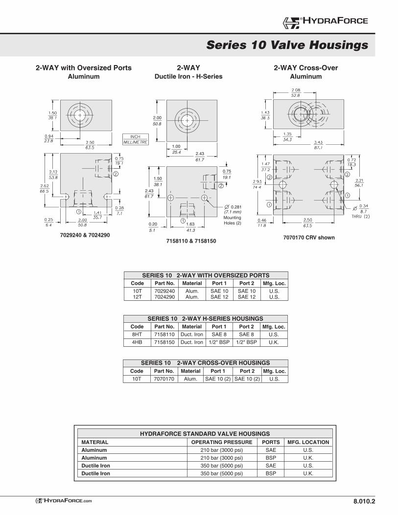
2-WAY with Oversized PortsAluminum
8.010.2
2-WAY Cross-Over Aluminum
Series 10 Valve Housings
Code
10T12T
Part No.
70292407024290
Material
Alum.Alum.
Port 1
SAE 10SAE 12
Port 2
SAE 10SAE 12
Mfg. Loc.
U.S.U.S.
SERIES 10 2-WAY WITH OVERSIZED PORTS
MATERIAL
Aluminum
Aluminum
Ductile Iron
Ductile Iron
OPERATING PRESSURE
210 bar (3000 psi)
210 bar (3000 psi)
350 bar (5000 psi)
350 bar (5000 psi)
PORTS
SAE
BSP
SAE
BSP
MFG. LOCATION
U.S.
U.K.
U.S.
U.K.
HYDRAFORCE STANDARD VALVE HOUSINGS
®HYDRAFORCE
HYDRAFORCE.com®
7029240 & 70242907158110 & 7158150
0.75
19.11.50
38.1
1.0025.4 2.43
61.7
2.00
50.8
0.20
5.1
1.63
41.3
2.4361.7
0.281 (7.1 mm)MountingHoles (2)
7070170 CRV shown
2-WAY Ductile Iron - H-Series
Code
8HT
4HB
Material
Duct. Iron
Duct. Iron
Port 1
SAE 8
1/2" BSP
Port 2
SAE 8
1/2" BSP
SERIES 10 2-WAY H-SERIES HOUSINGS
Code
10T
Part No.
7070170
Material
Alum.
Port 1
SAE 10 (2)
Port 2
SAE 10 (2)
Mfg. Loc.
U.S.
SERIES 10 2-WAY CROSS-OVER HOUSINGS
HOUSINGS AND ACCESSORY PRODUCTS
8.010.3 HYDRAFORCE.com®
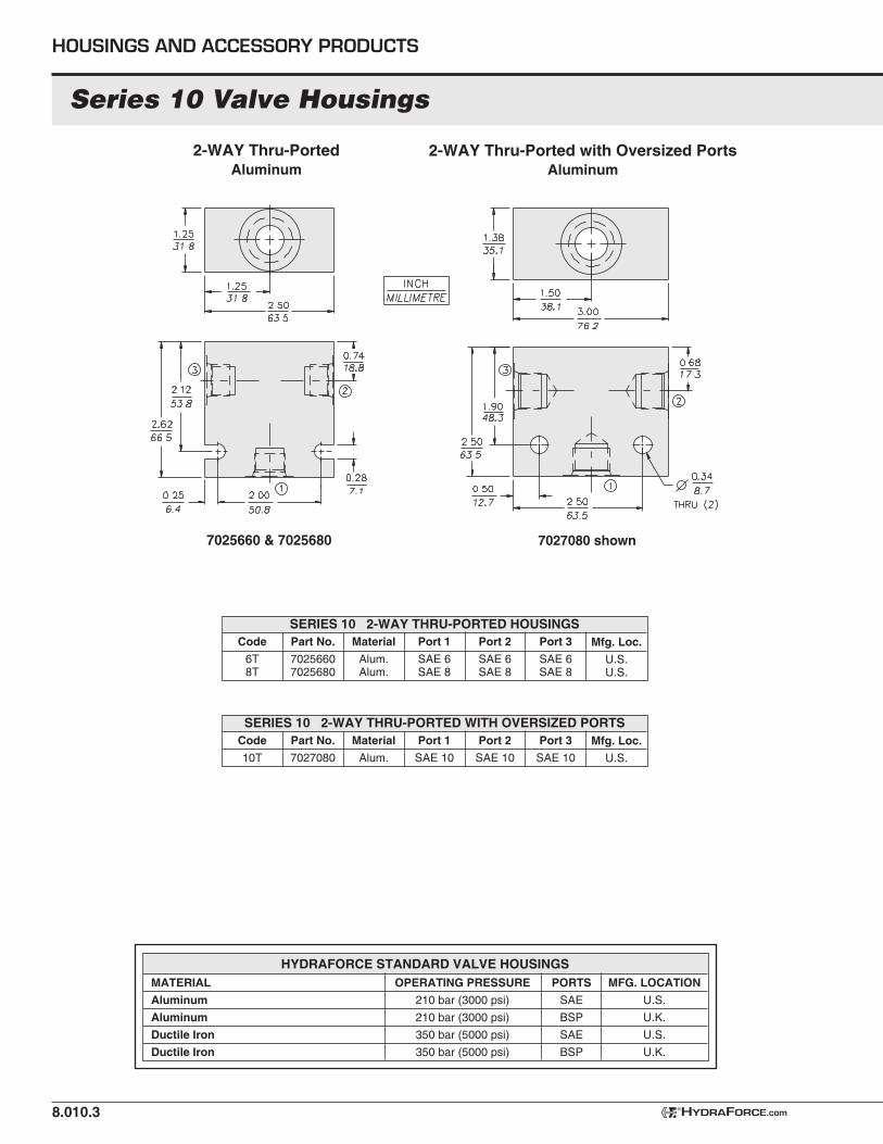
2-WAY Thru-PortedAluminum
MATERIAL
Aluminum
Aluminum
Ductile Iron
Ductile Iron
OPERATING PRESSURE
210 bar (3000 psi)
210 bar (3000 psi)
350 bar (5000 psi)
350 bar (5000 psi)
PORTS
SAE
BSP
SAE
BSP
MFG. LOCATION
U.S.
U.K.
U.S.
U.K.
HYDRAFORCE STANDARD VALVE HOUSINGS
7027080 shown7025660 & 7025680
2-WAY Thru-Ported with Oversized PortsAluminum
Series 10 Valve Housings
Code
6T 8T
Code
10T
Part No.
70256607025680
Part No.
7027080
Material
Alum.Alum.
Material
Alum.
Port 1
SAE 6SAE 8
Port 1
SAE 10
Port 2
SAE 6SAE 8
Port 2
SAE 10
Mfg. Loc.
U.S.U.S.
Mfg. Loc.
U.S.
SERIES 10 2-WAY THRU-PORTED HOUSINGS
SERIES 10 2-WAY THRU-PORTED WITH OVERSIZED PORTS
Port 3
SAE 6SAE 8
Port 3
SAE 10
Code
6T 8T 3B
6TD8TD
3BD
8.010.4
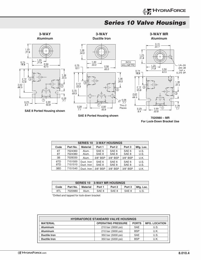
3-WAYAluminum
MATERIAL
Aluminum
Aluminum
Ductile Iron
Ductile Iron
OPERATING PRESSURE
210 bar (3000 psi)
210 bar (3000 psi)
350 bar (5000 psi)
350 bar (5000 psi)
PORTS
SAE
BSP
SAE
BSP
MFG. LOCATION
U.S.
U.K.
U.S.
U.K.
HYDRAFORCE STANDARD VALVE HOUSINGS
HYDRAFORCE.com®
3-WAYDuctile Iron
SERIES 10 3-WAY HOUSINGS
Code
8TL
Part No.
7020980
Material
Alum.
Port 1
SAE 8
Port 2
SAE 8
Mfg. Loc.
U.S.
SERIES 10 3-WAY MR HOUSINGSPort 3
SAE 8
3-WAY MRAluminum
SAE 8 Ported Housing shown
7020980 – MRFor Lock-Down Bracket Use
SAE 8 Ported Housing shown
2.5665.0
1.3634.6
2.7569.9
2.1253.8
0.7519.1
1.3033.0
1.3834.9
Thru 2Places
0.287.1
2.0050.8
0.287.1
Part No.
702436070243807028330
71515007151510
7151540
Material
Alum.Alum.
Alum.
Duct. IronDuct. Iron
Duct. Iron
Port 1
SAE 6SAE 8
3/8" BSP
SAE 6SAE 8
3/8" BSP
Port 2
SAE 6SAE 8
3/8" BSP
SAE 6SAE 8
3/8" BSP
Mfg. Loc.
U.S.U.S.
U.K.
U.S.U.S.
U.K.
Port 3
SAE 6SAE 8
3/8" BSP
SAE 6SAE 8
3/8" BSP
Series 10 Valve Housings
®HYDRAFORCE
*Drilled and tapped for lock-down bracket
Material
Duct. Iron
Duct. Iron
8.010.5
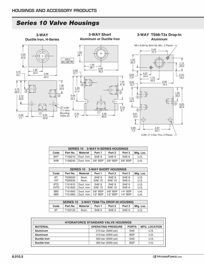
Code
8HT
3HB
3-WAY ShortAluminum or Ductile Iron
HOUSINGS AND ACCESSORY PRODUCTS
SERIES 10 3-WAY SHORT HOUSINGS
HYDRAFORCE.com®
MATERIAL
Aluminum
Aluminum
Ductile Iron
Ductile Iron
OPERATING PRESSURE
210 bar (3000 psi)
210 bar (3000 psi)
350 bar (5000 psi)
350 bar (5000 psi)
PORTS
SAE
BSP
SAE
BSP
MFG. LOCATION
U.S.
U.K.
U.S.
U.K.
HYDRAFORCE STANDARD VALVE HOUSINGS
3-WAY TS98-T3x Drop-InAluminum
Code
6T
Part No.
7150120
Material
Alum.
Port 1
SAE 6
Port 2
SAE 6
Mfg. Loc.
U.S.
SERIES 10 3-WAY TS98-T3x DROP-IN HOUSINGPort 3
SAE 6
M5 x 8-6H by 9mm Dp. Min., 2 Places
4
2
3
1.4336.3
1.7544.5
1.1428.9
3.2582.6
0.7218.2
1.2030.5
0.6215.7
1.7043.2
2.4371.7
0.9724.6
0.297.37
2.9374.4
2.3760.1
0.281 (7.1) Dia. Thru, 2 Places
0.297.3
0.4110.4
0.75
19.1
1.36
34.6
1.3033.0 2.56
65.0
2.00
50.8
0.287.1
2.0050.8
2.7569.9
2.1253.8
0.281 (7.1 mm)MountingHoles (2)
Code
8T 10T
8TD 10TD
3BD 4BD
Part No.
70265207026530
71516107151620
71516507151660
Material
Alum.Alum.
Duct. IronDuct. Iron
Duct. IronDuct. Iron
Port 1
SAE 8SAE 10
SAE 8SAE 10
3/8" BSP1/2" BSP
Port 2
SAE 8SAE 10
SAE 8SAE 10
3/8" BSP1/2" BSP
Mfg. Loc.
U.S.U.S.
U.S.U.S.
U.K.U.K.
Port 3
SAE 6SAE 6
SAE 6SAE 6
1/4" BSP1/4" BSP
Part No.
7158210
7158240
Port 1
SAE 8
3/8" BSP
Port 2
SAE 8
3/8" BSP
Mfg. Loc.
U.S.
U.K.
SERIES 10 3-WAY H-SERIES HOUSINGSPort 3
SAE 8
3/8" BSP
3-WAYDuctile Iron, H-Series
Series 10 Valve Housings
8.010.6HYDRAFORCE.com®
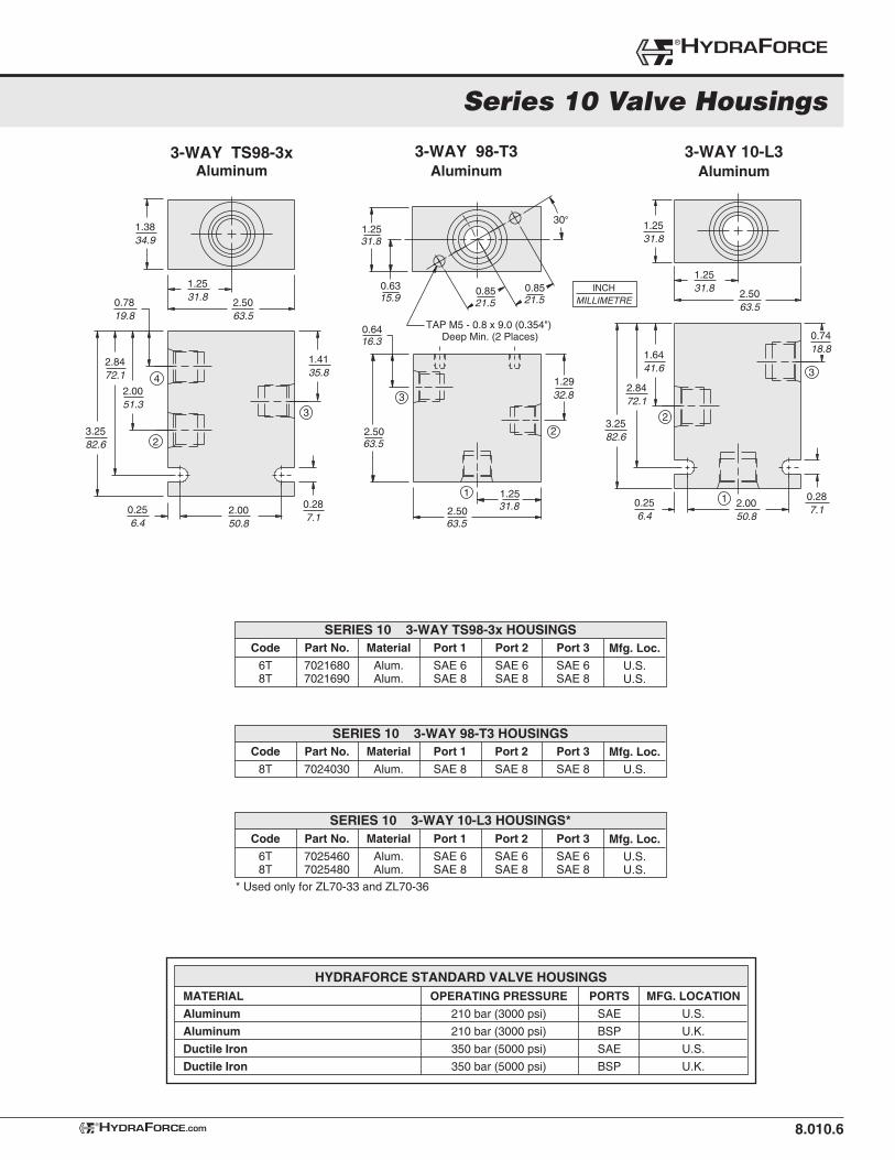
3-WAY 10-L3Aluminum
Code
6T 8T
Part No.
70254607025480
Material
Alum.Alum.
Port 1
SAE 6SAE 8
Port 2
SAE 6SAE 8
Mfg. Loc.
U.S.U.S.
SERIES 10 3-WAY 10-L3 HOUSINGS*Port 3
SAE 6SAE 8
* Used only for ZL70-33 and ZL70-36
MATERIAL
Aluminum
Aluminum
Ductile Iron
Ductile Iron
OPERATING PRESSURE
210 bar (3000 psi)
210 bar (3000 psi)
350 bar (5000 psi)
350 bar (5000 psi)
PORTS
SAE
BSP
SAE
BSP
MFG. LOCATION
U.S.
U.K.
U.S.
U.K.
HYDRAFORCE STANDARD VALVE HOUSINGS
3-WAY TS98-3xAluminum
3-WAY 98-T3Aluminum
Code
6T 8T
Part No.
70216807021690
Material
Alum.Alum.
Port 1
SAE 6SAE 8
Port 2
SAE 6SAE 8
Mfg. Loc.
U.S.U.S.
SERIES 10 3-WAY TS98-3x HOUSINGSPort 3
SAE 6SAE 8
Code
8T
Part No.
7024030
Material
Alum.
Port 1
SAE 8
Port 2
SAE 8
Mfg. Loc.
U.S.
SERIES 10 3-WAY 98-T3 HOUSINGSPort 3
SAE 8
INCHMILLIMETRE
1.2531.8
1.2531.8 2.50
63.5
1.6441.6
2.8472.1
3.2582.6
2.0050.8
0.287.1
3
1
0.7418.8
0.256.4
2
1.3834.9
1.2531.8 2.50
63.50.7819.8
2.8472.1
2.0051.3
3.2582.6
2.0050.8
0.287.1
1.4135.8
3
0.256.4
2
4
0.6416.3
2.5063.5
0.63
TAP M5 - 0.8 x 9.0 (0.354") Deep Min. (2 Places)
15.90.8521.5
0.8521.5
1.2531.8
1
30°
1.2531.82.50
63.5
1.2932.8
2
3
Series 10 Valve Housings
®HYDRAFORCE
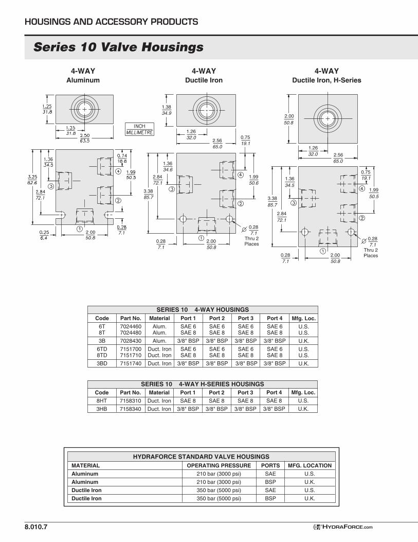
Code
6T 8T
3B
6TD8TD
3BD
Part No.
70244607024480
7028430
71517007151710
7151740
Material
Alum.Alum.
Alum.
Duct. IronDuct. Iron
Duct. Iron
Port 1
SAE 6SAE 8
3/8" BSP
SAE 6SAE 8
3/8" BSP
Port 2
SAE 6SAE 8
3/8" BSP
SAE 6 SAE 8
3/8" BSP
Mfg. Loc.
U.S.U.S.
U.K.
U.S.U.S.
U.K.
Port 3
SAE 6SAE 8
3/8" BSP
SAE 6 SAE 8
3/8" BSP
Port 4
SAE 6SAE 8
3/8" BSP
SAE 6SAE 8
3/8" BSP
Port 4
SAE 8
3/8" BSP
8.010.7
4-WAYAluminum
HOUSINGS AND ACCESSORY PRODUCTS
SERIES 10 4-WAY HOUSINGS
HYDRAFORCE.com®
4-WAYDuctile Iron
MATERIAL
Aluminum
Aluminum
Ductile Iron
Ductile Iron
OPERATING PRESSURE
210 bar (3000 psi)
210 bar (3000 psi)
350 bar (5000 psi)
350 bar (5000 psi)
PORTS
SAE
BSP
SAE
BSP
MFG. LOCATION
U.S.
U.K.
U.S.
U.K.
HYDRAFORCE STANDARD VALVE HOUSINGS
2.5665.0
0.7519.1
3.3885.7
2.8472.1
1.2632.0
1.3834.9
Thru 2Places
0.287.1
Thru 2Places
0.287.1
0.287.1
1.9950.6
1.3634.6
2.0050.8
0.287.1
3.3885.7
2.8472.1
1.3634.5
0.7519.1
1.9950.5
1.2632.0 2.56
65.0
2.0050.8
2.0050.8
4-WAYDuctile Iron, H-Series
Code
8HT
3HB
Part No.
7158310
7158340
Material
Duct. Iron
Duct. Iron
Port 1
SAE 8
3/8" BSP
Port 2
SAE 8
3/8" BSP
Mfg. Loc.
U.S.
U.K.
Port 3
SAE 8
3/8" BSP
SERIES 10 4-WAY H-SERIES HOUSINGS
Series 10 Valve Housings
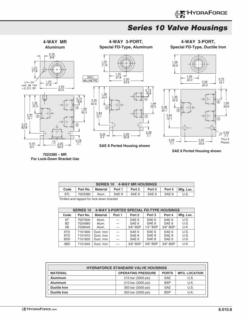
Code
6T 8D 5B
6TD8TD8DD
3BD
Part No.
702700070249807028540
715190071519107151920
7151940
Material
Alum.Alum.Alum.
Duct. IronDuct. IronDuct. Iron
Duct. Iron
Port 1
———
———
—
Port 2
SAE 6SAE 6
3/8" BSP
SAE 6SAE 8SAE 6
3/8" BSP
Mfg. Loc.
U.S.U.S.U.K.
U.S.U.S.U.S.
U.K.
Port 3
SAE 6SAE 8
1/2" BSP
SAE 6SAE 8SAE 8
3/8" BSP
Port 4
SAE 6SAE 6
3/8" BSP
SAE 6SAE 8SAE 6
3/8" BSP
8.010.8HYDRAFORCE.com®
MATERIAL
Aluminum
Aluminum
Ductile Iron
Ductile Iron
OPERATING PRESSURE
210 bar (3000 psi)
210 bar (3000 psi)
350 bar (5000 psi)
350 bar (5000 psi)
PORTS
SAE
BSP
SAE
BSP
MFG. LOCATION
U.S.
U.K.
U.S.
U.K.
HYDRAFORCE STANDARD VALVE HOUSINGS
4-WAY 3-PORT,Special FD-Type, Aluminum
SERIES 10 4-WAY 3-PORTED SPECIAL FD-TYPE HOUSINGS
4-WAY MRAluminum
Code
8TL
Part No.
7023380
Material
Alum.
Port 1
SAE 8
Port 2
SAE 8
Mfg. Loc.
U.S.
SERIES 10 4-WAY MR HOUSINGSPort 3
SAE 8
Port 4
SAE 8
7023380 – MRFor Lock-Down Bracket Use
SAE 8 Ported Housing shownSAE 8 Ported Housing shown
2.5665.0
0.7519.1
3.3885.7
2.8472.1
1.2632.0
1.3834.9
Thru 2Places
0.287.1
1.9950.6
1.3634.6
2.0050.8
0.287.1
4-WAY 3-PORT,Special FD-Type, Ductile Iron
Series 10 Valve Housings
®HYDRAFORCE
*Drilled and tapped for lock-down bracket
8.010.9
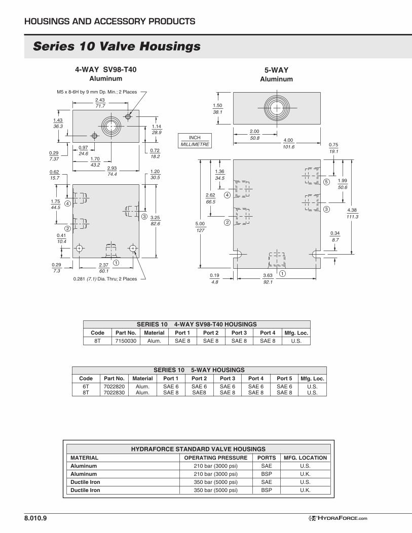
5-WAYAluminum
HOUSINGS AND ACCESSORY PRODUCTS
Code
6T 8T
Part No.
70228207022830
Material
Alum.Alum.
Port 1
SAE 6SAE 8
Port 2
SAE 6SAE8
Mfg. Loc.
U.S.U.S.
SERIES 10 5-WAY HOUSINGSPort 3
SAE 6SAE 8
Port 4
SAE 6SAE 8
Port 5
SAE 6SAE 8
HYDRAFORCE.com®
4-WAY SV98-T40Aluminum
Code
8T
Part No.
7150030
Material
Alum.
Port 1
SAE 8
Port 2
SAE 8
Mfg. Loc.
U.S.
SERIES 10 4-WAY SV98-T40 HOUSINGSPort 3
SAE 8
Port 4
SAE 8
MATERIAL
Aluminum
Aluminum
Ductile Iron
Ductile Iron
OPERATING PRESSURE
210 bar (3000 psi)
210 bar (3000 psi)
350 bar (5000 psi)
350 bar (5000 psi)
PORTS
SAE
BSP
SAE
BSP
MFG. LOCATION
U.S.
U.K.
U.S.
U.K.
HYDRAFORCE STANDARD VALVE HOUSINGS
1.4336.3
1.7544.5
1.1428.9
3.2582.6
0.7218.2
1.2030.5
0.6215.7
1.7043.2
2.4371.7
M5 x 8-6H by 9 mm Dp. Min.; 2 Places
0.9724.60.29
7.37
2.9374.4
2.3760.1
0.281 (7.1) Dia. Thru; 2 Places
0.297.3
0.4110.4
4
2
1
3
INCHMILLIMETRE
1.3634.5
2.6266.5
5.00127
1.5038.1
2.0050.8
1.9950.6
4.38111.3
0.7519.1
4
2
1
5
3
0.348.7
4.00101.6
0.194.8
3.6392.1
Series 10 Valve Housings
8.010.10
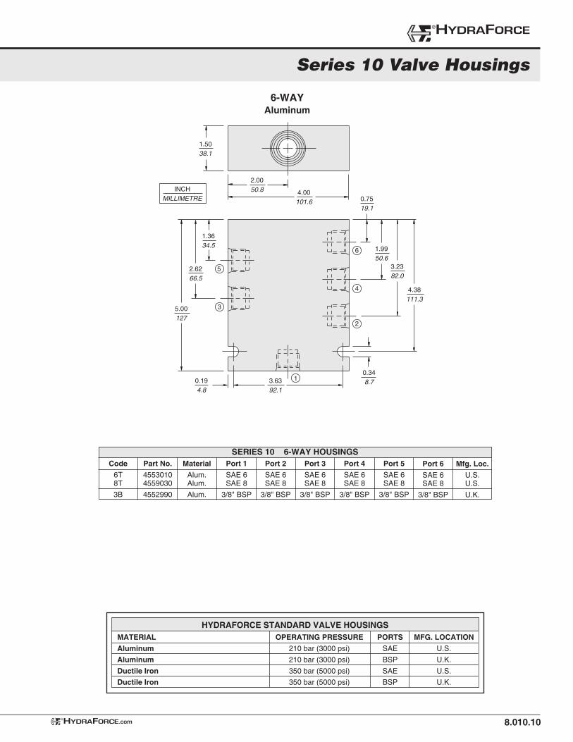
6-WAYAluminum
SERIES 10 6-WAY HOUSINGS
HYDRAFORCE.com®
MATERIAL
Aluminum
Aluminum
Ductile Iron
Ductile Iron
OPERATING PRESSURE
210 bar (3000 psi)
210 bar (3000 psi)
350 bar (5000 psi)
350 bar (5000 psi)
PORTS
SAE
BSP
SAE
BSP
MFG. LOCATION
U.S.
U.K.
U.S.
U.K.
HYDRAFORCE STANDARD VALVE HOUSINGS
INCHMILLIMETRE
1.3634.5
2.6266.5
5.00127
1.5038.1
2.0050.8
1.9950.6
3.2382.0
4.38111.3
0.7519.1
5
3
1
6
4
2
0.348.7
4.00101.6
0.194.8
3.6392.1
Code
6T 8T
3B
Part No.
45530104559030
4552990
Material
Alum.Alum.
Alum.
Port 1
SAE 6SAE 8
3/8" BSP
Port 2
SAE 6SAE 8
3/8" BSP
Port 3
SAE 6SAE 8
3/8" BSP
Port 4
SAE 6SAE 8
3/8" BSP
Port 5
SAE 6SAE 8
3/8" BSP
Port 6
SAE 6SAE 8
3/8" BSP
Mfg. Loc.
U.S.U.S.
U.K.
Series 10 Valve Housings
®HYDRAFORCE
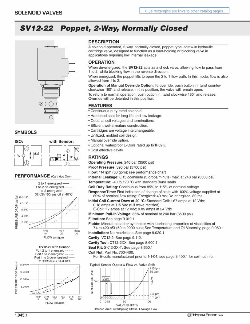
SV12-22 Poppet, 2-Way, Normally Closed
DESCRIPTIONA solenoid-operated, 2-way, normally closed, poppet-type, screw-in hydraulic cartridge valve, designed to function as a load-holding or blocking valve in applications requiring low internal leakage.
OPERATIONWhen de-energized, the SV12-22 acts as a check valve, allowing flow to pass from 1 to 2, while blocking flow in the reverse direction.When energized, the poppet lifts to open the 2 to 1 flow path. In this mode, flow is also allowed from 1 to 2.Operation of Manual Override Option: To override, push button in, twist counter-clockwise 180° and release. In this position, the valve will remain open.To return to normal operation, push button in, twist clockwise 180° and release. Override will be detented in this position.
FEATURES• Continuous-duty rated solenoid.• Hardened seat for long life and low leakage.• Optional coil voltages and terminations.• Efficient wet-armature construction.• Cartridges are voltage interchangeable.• Unitized, molded coil design.• Manual override option.• Optional waterproof E-Coils rated up to IP69K.• Cost effective cavity.
RATINGSOperating Pressure: 240 bar (3500 psi)Proof Pressure: 390 bar (5700 psi)Flow: 114 lpm (30 gpm); see performance chartInternal Leakage: 0.15 cc/minute (3 drops/minute) max. at 240 bar (3500 psi)Temperature: -40 to 120 °C with standard Buna sealsCoil Duty Rating: Continuous from 85% to 115% of nominal voltageResponse Time: First indication of change of state with 100% voltage supplied at
80% of nominal flow rating: Energized: 40 ms; De-energized: 80 msInitial Coil Current Draw at 20 °C: Standard Coil: 1.67 amps at 12 Vdc;
0.18 amps at 115 Vac (full wave rectified). E-Coil: 1.7 amps at 12 Vdc; 0.85 amps at 24 Vdc
Minimum Pull-in Voltage: 85% of nominal at 240 bar (3500 psi)Filtration: See page 9.010.1Fluids: Mineral-based or synthetics with lubricating properties at viscosities of
7.4 to 420 cSt (50 to 2000 sus); See Temperature and Oil Viscosity, page 9.060.1Installation: No restrictions; See page 9.020.1Cavity: VC12-2; See page 9.112.1Cavity Tool: CT12-2XX; See page 8.600.1Seal Kit: SK12-2X-T; See page 8.650.1Coil Nut: Part No. 7004400;
For E-coils manufactured prior to 1-1-04, see page 3.400.1 for coil nut info.
ISO: with Sensor:
SYMBOLS
1.045.1
10.3/150
8.3/120
6.2/90
4.1/60
2.1/30
37.910
75.820
113.630
FLOW lpm/gpm
PR
ES
SU
RE
DR
OP
bar
/psi
2 to 1 energized ——1 to 2 de-energized – – –
1 to 2 energized - - - -32 cSt/150 sus oil at 40°C
PERFORMANCE (Cartridge Only)
SOLENOID VALVES
HYDRAFORCE.com®
27.6/400
20.7/300
13.8/200
6.9/100
PR
ES
SU
RE
DR
OP
bar
/psi
SV12-22 with SensorPort 2 to 1 energized - - - - -Port 1 to 2 energized — - —
Port 1 to 2 de-energized ——32 cSt/150 sus oil at 40°C
18.95
37.910
56.815
94.625
FLOW lpm/gpm
75.720
11430
VOUT
VALVE SHIFT %
FLO
W
Vcc
SE
NS
OR
OU
TP
UT
Typical Sensor Output & Flow vs. Valve Shift
0
0.4 lpm0.1 gpm
113 lpm30 gpm
1015 50 100
Hatched Area: Overlapping Stroke, Leakage Flow
SV12-22
DIMENSIONS
1.045.2
1.6241.1
1.84 DIA.46.7
0.4511.4
E-CoilView
StandardCoil View
2.3860.5
TORQUE33-37 lbf•ft(44.7-50.2 N•m)
TORQUE5-7 lbf•ft(6.8-9.5 N•m)
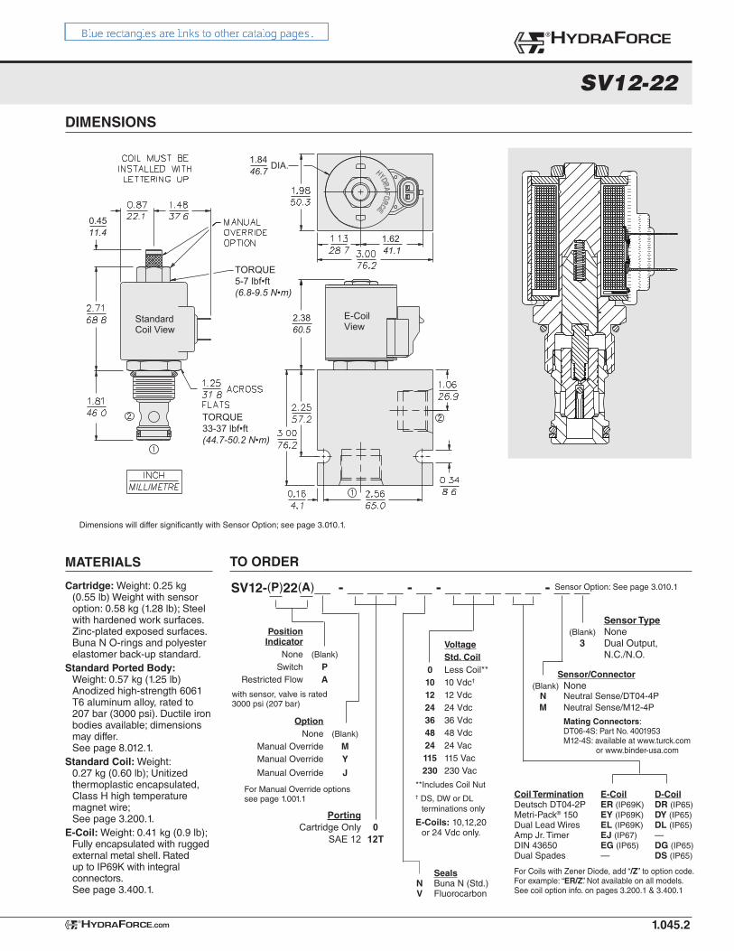
MATERIALS
Cartridge: Weight: 0.25 kg (0.55 lb) Weight with sensor option: 0.58 kg (1.28 lb); Steel with hardened work surfaces. Zinc-plated exposed surfaces. Buna N O-rings and polyester elastomer back-up standard.
Standard Ported Body: Weight: 0.57 kg (1.25 lb) Anodized high-strength 6061 T6 aluminum alloy, rated to 207 bar (3000 psi). Ductile iron bodies available; dimensions may differ. See page 8.012.1.
Standard Coil: Weight: 0.27 kg (0.60 lb); Unitized thermoplastic encapsulated, Class H high temperature magnet wire; See page 3.200.1.
E-Coil: Weight: 0.41 kg (0.9 lb); Fully encapsulated with rugged external metal shell. Rated up to IP69K with integral connectors. See page 3.400.1.
TO ORDER
®HYDRAFORCE
HYDRAFORCE.com®
SV12-(P)22(A)__ - __ __ __ - __ - __ __ __ __ __ - __ __
Option None (Blank)
Manual Override M Manual Override Y
Manual Override J
Position Indicator None (Blank)
Switch P Restricted Flow A
For Manual Override optionssee page 1.001.1
with sensor, valve is rated 3000 psi (207 bar)
Voltage Std. Coil 0 Less Coil** 10 10 Vdc†
12 12 Vdc 24 24 Vdc 36 36 Vdc 48 48 Vdc 24 24 Vac 115 115 Vac 230 230 Vac
**Includes Coil Nut† DS, DW or DL
terminations only
E-Coils: 10,12,20 or 24 Vdc only.
For Coils with Zener Diode, add “/Z” to option code. For example: “ER/Z”. Not available on all models. See coil option info. on pages 3.200.1 & 3.400.1
Coil Termination E-Coil D-CoilDeutsch DT04-2P ER (IP69K) DR (IP65)Metri-Pack® 150 EY (IP69K) DY (IP65)Dual Lead Wires EL (IP69K) DL (IP65)Amp Jr. Timer EJ (IP67) —DIN 43650 EG (IP65) DG (IP65)Dual Spades — DS (IP65)
Sensor/Connector (Blank) None N Neutral Sense/DT04-4P M Neutral Sense/M12-4P
Mating Connectors: DT06-4S: Part No. 4001953 M12-4S: available at www.turck.com or www.binder-usa.com
Seals N Buna N (Std.) V Fluorocarbon
Sensor Option: See page 3.010.1
Sensor Type (Blank) None 3 Dual Output, N.C./N.O.
Dimensions will differ significantly with Sensor Option; see page 3.010.1.
Porting Cartridge Only 0 SAE 12 12T
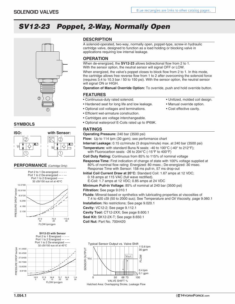
SV12-23 Poppet, 2-Way, Normally Open
DESCRIPTIONA solenoid-operated, two-way, normally open, poppet-type, screw-in hydraulic cartridge valve, designed to function as a load holding or blocking valve in applications requiring low internal leakage.
OPERATIONWhen de-energized, the SV12-23 allows bidirectional flow from 2 to 1. With the sensor option, the neutral sensor will signal OFF or LOW.When energized, the valve’s poppet closes to block flow from 2 to 1. In this mode, the cartridge allows free reverse flow from 1 to 2 after overcoming the solenoid force (requires 3.4 to 10.3 bar / 50 to 150 psi). With the sensor option, the neutral sensor will signal ON or HIGH.Operation of Manual Override Option: To override, push and hold override button.
FEATURES• Continuous-duty rated solenoid. • Unitized, molded coil design.• Hardened seat for long life and low leakage. • Manual override option.• Optional coil voltages and terminations. • Cost effective cavity.• Efficient wet-armature construction.• Cartridges are voltage interchangeable.• Optional waterproof E-Coils rated up to IP69K.
RATINGSOperating Pressure: 240 bar (3500 psi)Flow: Up to 114 lpm (30 gpm); see performance chartInternal Leakage: 0.15 cc/minute (3 drops/minute) max. at 240 bar (3500 psi)Temperature: with standard Buna N seals: -40 to 100°C (-40° to 212°F);
with Fluorocarbon seals: -26 to 204°C (-15°F to 400°F)Coil Duty Rating: Continuous from 85% to 115% of nominal voltageResponse Time: First indication of change of state with 100% voltage supplied at
80% of nominal flow rating: Energized: 80 msec.; De-energized: 30 msec. Response Time with Sensor: 158 ms pull-in, 57 ms drop-out
Initial Coil Current Draw at 20°C: Standard Coil: 1.67 amps at 12 VDC; 0.18 amps at 115 VAC (full wave rectified). E-Coil: 1.7 amps at 12 VDC; 0.85 amps at 24 VDC
Minimum Pull-in Voltage: 85% of nominal at 240 bar (3500 psi)Filtration: See page 9.010.1 Fluids: Mineral-based or synthetics with lubricating properties at viscosities of
7.4 to 420 cSt (50 to 2000 sus); See Temperature and Oil Viscosity, page 9.060.1Installation: No restrictions; See page 9.020.1Cavity: VC12-2; See page 9.112.1Cavity Tool: CT12-2XX; See page 8.600.1Seal Kit: SK12-2X-T; See page 8.650.1Coil Nut: Part No. 7004420
ISO:
PERFORMANCE (Cartridge Only)
SYMBOLS
with Sensor:
1.054.1
10.3/150
12.4/180
8.3/120
6.2/90
4.1/60
2.1/30
37.910
75.820
113.630
FLOW lpm/gpm
PR
ES
SU
RE
DR
OP
bar
/psi
Port 2 to 1 De-energized - - - - -Port 1 to 2 De-energized — - —
Port 1 to 2 Energized ——32 cSt/150 sus oil at 40°C
SOLENOID VALVES
HYDRAFORCE.com®
SV12-23 with SensorPort 2 to 1 Energized - - - - -Port 1 to 2 Energized — - —
Port 1 to 2 De-energized ——32 cSt/150 sus oil at 40°C
27.6/400
35.4/500
41.4/600
20.7/300
13.8/200
6.9/100
18.95
37.910
56.815
75.720
FLOW lpm/gpm
PR
ES
SU
RE
DR
OP
bar
/psi
94.625
11430
VALVE SHIFT %
FLO
W
Vcc
SE
NS
OR
OU
TP
UT
Typical Sensor Output vs. Valve Shift
0
0.4 lpm0.1 gpm
113.6 lpm30 gpm
68 7350 100
VOUT
Hatched Area: Overlapping Stroke, Leakage Flow
SV12-23
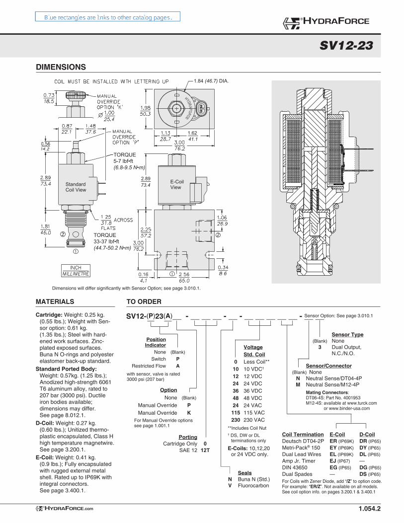
DIMENSIONS
1.054.2
1.62
2.89
41.1
73.4
1.84 (46.7) DIA.
E-CoilViewStandard
Coil View
TORQUE33-37 lbf•ft(44.7-50.2 N•m)
TORQUE5-7 lbf•ft(6.8-9.5 N•m)
®HYDRAFORCE
HYDRAFORCE.com®
Dimensions will differ significantly with Sensor Option; see page 3.010.1.
TO ORDER
SV12-(P)23(A)__ - __ __ __ - __ - __ __ __ __ __ - __ __
Option None (Blank)
Manual Override P Manual Override K
For Manual Override optionssee page 1.001.1
Cartridge: Weight: 0.25 kg. (0.55 lbs.); Weight with Sen-sor option: 0.61 kg. (1.35 lbs.); Steel with hard-ened work surfaces. Zinc-plated exposed surfaces. Buna N O-rings and polyester elastomer back-up standard.
Standard Ported Body: Weight: 0.57kg. (1.25 lbs.); Anodized high-strength 6061 T6 aluminum alloy, rated to 207 bar (3000 psi). Ductile iron bodies available; dimensions may differ. See page 8.012.1.
D-Coil: Weight: 0.27 kg. (0.60 lbs.); Unitized thermo-plastic encapsulated, Class H high temperature magnetwire. See page 3.200.1.
E-Coil: Weight: 0.41 kg. (0.9 lbs.); Fully encapsulated with rugged external metal shell. Rated up to IP69K with integral connectors. See page 3.400.1.
Voltage Std. Coil 0 Less Coil** 10 10 VDC†
12 12 VDC 24 24 VDC 36 36 VDC 48 48 VDC 24 24 VAC 115 115 VAC 230 230 VAC
**Includes Coil Nut† DS, DW or DL
terminations only
E-Coils: 10,12,20 or 24 VDC only.
MATERIALS
For Coils with Zener Diode, add “/Z” to option code. For example: “ER/Z”. Not available on all models. See coil option info. on pages 3.200.1 & 3.400.1
Coil Termination E-Coil D-CoilDeutsch DT04-2P ER (IP69K) DR (IP65)Metri-Pack® 150 EY (IP69K) DY (IP65)Dual Lead Wires EL (IP69K) DL (IP65)Amp Jr. Timer EJ (IP67) —DIN 43650 EG (IP65) DG (IP65)Dual Spades — DS (IP65) Seals
N Buna N (Std.) V Fluorocarbon
Sensor Option: See page 3.010.1
Sensor/Connector (Blank) None N Neutral Sense/DT04-4P M Neutral Sense/M12-4P Mating Connectors: DT06-4S: Part No. 4001953 M12-4S: available at www.turck.com or www.binder-usa.com
Position Indicator None (Blank)
Switch P Restricted Flow A
with sensor, valve is rated 3000 psi (207 bar)
Sensor Type (Blank) None 3 Dual Output, N.C./N.O.
Porting Cartridge Only 0 SAE 12 12T
USASI/ISO:
SYMBOLS
1.094.1
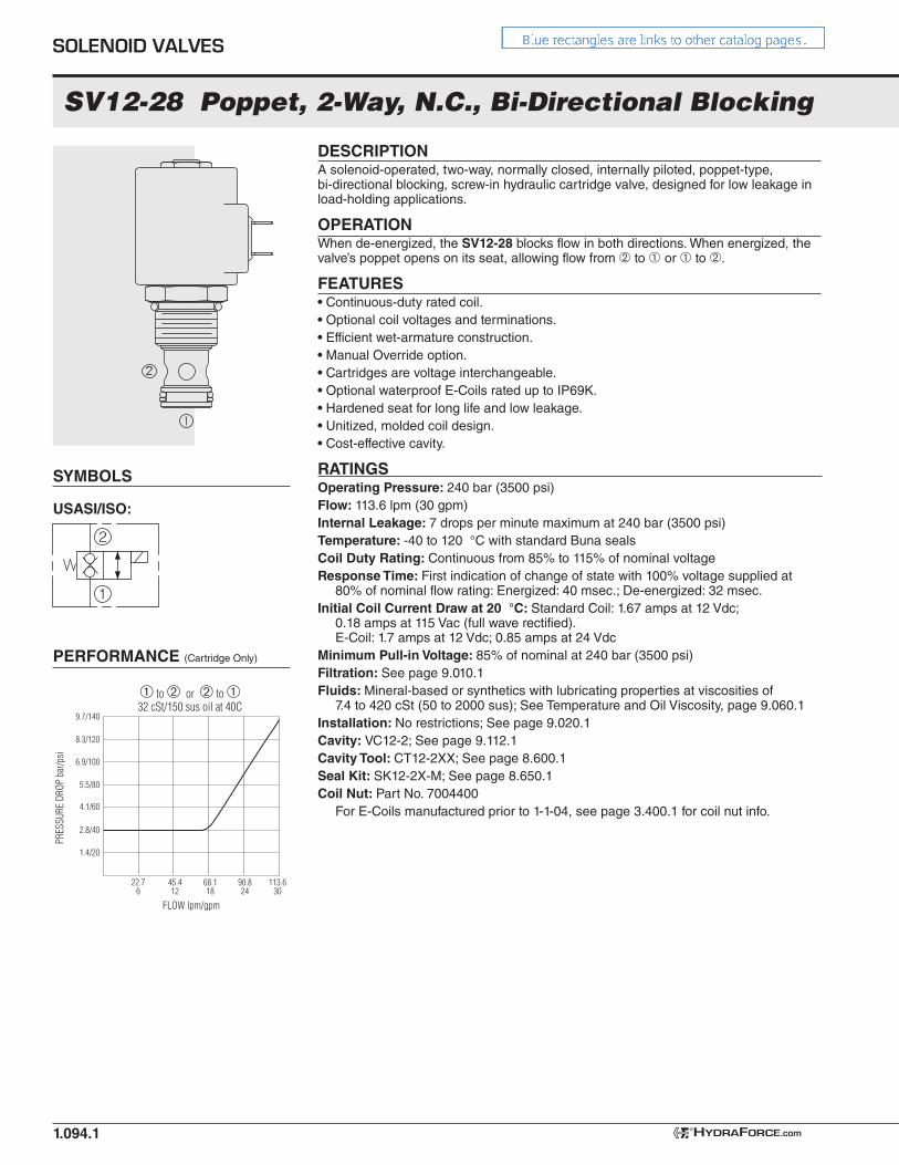
SV12-28 Poppet, 2-Way, N.C., Bi-Directional Blocking
PERFORMANCE (Cartridge Only)
1
2
DESCRIPTIONA solenoid-operated, two-way, normally closed, internally piloted, poppet-type, bi-directional blocking, screw-in hydraulic cartridge valve, designed for low leakage in load-holding applications.
OPERATIONWhen de-energized, the SV12-28 blocks flow in both directions. When energized, the valve’s poppet opens on its seat, allowing flow from ➁ to ➀ or ➀ to ➁.
FEATURES• Continuous-duty rated coil.• Optional coil voltages and terminations.• Efficient wet-armature construction.• Manual Override option.• Cartridges are voltage interchangeable.• Optional waterproof E-Coils rated up to IP69K.• Hardened seat for long life and low leakage.• Unitized, molded coil design.• Cost-effective cavity.
RATINGSOperating Pressure: 240 bar (3500 psi)Flow: 113.6 lpm (30 gpm)Internal Leakage: 7 drops per minute maximum at 240 bar (3500 psi)Temperature: -40 to 120 °C with standard Buna sealsCoil Duty Rating: Continuous from 85% to 115% of nominal voltageResponse Time: First indication of change of state with 100% voltage supplied at
80% of nominal flow rating: Energized: 40 msec.; De-energized: 32 msec.Initial Coil Current Draw at 20 °C: Standard Coil: 1.67 amps at 12 Vdc;
0.18 amps at 115 Vac (full wave rectified). E-Coil: 1.7 amps at 12 Vdc; 0.85 amps at 24 Vdc
Minimum Pull-in Voltage: 85% of nominal at 240 bar (3500 psi)Filtration: See page 9.010.1 Fluids: Mineral-based or synthetics with lubricating properties at viscosities of
7.4 to 420 cSt (50 to 2000 sus); See Temperature and Oil Viscosity, page 9.060.1Installation: No restrictions; See page 9.020.1Cavity: VC12-2; See page 9.112.1Cavity Tool: CT12-2XX; See page 8.600.1Seal Kit: SK12-2X-M; See page 8.650.1Coil Nut: Part No. 7004400 For E-Coils manufactured prior to 1-1-04, see page 3.400.1 for coil nut info.
5.5/80
6.9/100
8.3/120
9.7/140
4.1/60
2.8/40
1.4/20
22.76
45.412
68.118
90.824
FLOW lpm/gpm
PRES
SURE
DRO
P ba
r/psi
➀ to ➁ or ➁ to ➀32 cSt/150 sus oil at 40C
113.630
SOLENOID VALVES
HYDRAFORCE.com®
SV12-28
DIMENSIONS
1.094.2
1.6241.1
1.84DIA.
46.7
0.4511.4
E-CoilView
StandardCoil View
2.3860.5
TORQUE33-37 ft-lb(44.7-50.2 Nm)
TORQUE5-7 ft-lb(6.8-9.5 Nm)
MATERIALS
Cartridge: Weight: 0.25 kg (0.55 lb) Steel with hardened work surfaces. Zinc-plated exposed surfaces. Buna N O-rings and polyester elastomer back-up standard.
Standard Ported Body: Weight: 0.57 kg (1.25 lb) Anodized high-strength 6061 T6 aluminum alloy, rated to 207 bar (3000 psi). Ductile iron bodies available; dimensions may differ. See page 8.012.1.
Standard Coil: Weight: 0.27 kg (0.60 lb); Unitized thermoplastic encapsulated, Class H high temperature magnet wire; See page 3.200.1.
E-Coil: Weight: 0.41 kg (0.9 lb); Fully encapsulated with rugged external metal shell. Rated up to IP69K with integral connectors. Note: See page 3.400.1 for all E-Coil retrofit applications.
TO ORDER
SV12-28__ - __ __ __ - __ - __ __ __ __ __
Option None (Blank)
Manual Override M Manual Override Y Manual Override J
For Manual Override optionssee page 1.001.1
Seals Buna N (Std.) N Fluorocarbon V
Termination (Vdc) Std. Coil DS Dual Spades DG DIN 43650 DL Leadwires (2) DL/W Leads w/Weatherpak®
Connectors DR Deutsch DT04-2P
Termination (Vac) Std. Coil AG DIN 43650 AP 1/2 in. Conduit
Termination (Vdc) E-Coil ER Deutsch DT04-2P (IP69K Rated) EY Metri-Pack® 150 (IP69K Rated)
Coils with internal diode are available. Consult factory.
E-Coil 10 10 Vdc 12 12 Vdc 20 20 Vdc 24 24 Vdc
Voltage Std. Coil 0 Less Coil** 10 10 Vdc†
12 12 Vdc 24 24 Vdc 36 36 Vdc 48 48 Vdc 24 24 Vac 115 115 Vac 230 230 Vac**Includes Std. Coil Nut† DS, DW or DL
terminations only.
®HYDRAFORCE
HYDRAFORCE.com®
Porting Cartridge Only 0 SAE 12 12T
USASI:
SYMBOLS
1.099.1
SV12-29 Poppet, 2-Way, N.O., Bi-Directional Blocking
PERFORMANCE (Cartridge Only)
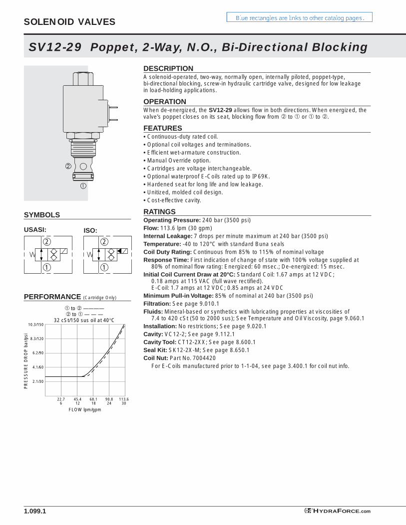
DESCRIPTIONA solenoid-operated, two-way, normally open, internally piloted, poppet-type, bi-directional blocking, screw-in hydraulic cartridge valve, designed for low leakage in load-holding applications.
OPERATIONWhen de-energized, the SV12-29 allows fl ow in both directions. When energized, the valve’s poppet closes on its seat, blocking fl ow from ➁ to ➀ or ➀ to ➁.
FEATURES• Continuous-duty rated coil.• Optional coil voltages and terminations.• Effi cient wet-armature construction.• Manual Override option.• Cartridges are voltage interchangeable.• Optional waterproof E-Coils rated up to IP69K.• Hardened seat for long life and low leakage.• Unitized, molded coil design.• Cost-effective cavity.
RATINGSOperating Pressure: 240 bar (3500 psi)Flow: 113.6 lpm (30 gpm)Internal Leakage: 7 drops per minute maximum at 240 bar (3500 psi)Temperature: -40 to 120°C with standard Buna sealsCoil Duty Rating: Continuous from 85% to 115% of nominal voltageResponse Time: First indication of change of state with 100% voltage supplied at
80% of nominal fl ow rating: Energized: 60 msec.; De-energized: 15 msec.Initial Coil Current Draw at 20°C: Standard Coil: 1.67 amps at 12 VDC;
0.18 amps at 115 VAC (full wave rectifi ed). E-Coil: 1.7 amps at 12 VDC; 0.85 amps at 24 VDC
Minimum Pull-in Voltage: 85% of nominal at 240 bar (3500 psi)Filtration: See page 9.010.1 Fluids: Mineral-based or synthetics with lubricating properties at viscosities of
7.4 to 420 cSt (50 to 2000 sus); See Temperature and Oil Viscosity, page 9.060.1Installation: No restrictions; See page 9.020.1Cavity: VC12-2; See page 9.112.1Cavity Tool: CT12-2XX; See page 8.600.1Seal Kit: SK12-2X-M; See page 8.650.1Coil Nut: Part No. 7004420 For E-Coils manufactured prior to 1-1-04, see page 3.400.1 for coil nut info.
6.2/90
8.3/120
10.3/150
4.1/60
2.1/30
22.76
45.412
68.118
90.824
FLOW lpm/gpm
PR
ES
SU
RE
DR
OP
bar
/psi
➀ to ➁ ————➁ to ➀ — — —
32 cSt/150 sus oil at 40°C
113.630
1
2
1
2
ISO:
SOLENOID VALVES
HYDRAFORCE.com®
SV12-29
DIMENSIONS
1.099.2
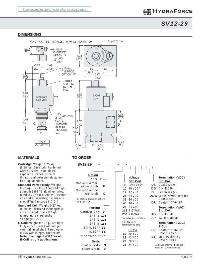
TORQUE -35 ft-lbs(47.4 Nm)max.
1.62
2.89
41.1
73.4
1.84 (46.7) DIA.
E-CoilView
StandardCoil View
Seals Buna N (Std.) N Fluorocarbon V
MATERIALS
Cartridge: Weight: 0.25 kg. (0.55 lbs.) Steel with hardened work surfaces. Zinc-plated exposed surfaces. Buna N O-rings and polyester elastomer back-up standard.
Standard Ported Body: Weight: 0.57 kg. (1.25 lbs.) Anodized high-strength 6061 T6 aluminum alloy, rated to 207 bar (3000 psi). Ductile iron bodies available; dimensions may differ. See page 8.012.1
Standard Coil: Weight: 0.27 kg. (0.60 lbs.) Unitized thermoplastic encapsulated, Class H high temperature magnetwire. See page 3.200.1
E-Coil: Weight: 0.41 kg. (0.9 lbs.); Fully encapsulated with rugged external metal shell. Rated up to IP69K with integral connectors. Note: See page 3.400.1 for all E-Coil retrofi t applications.
TO ORDER
SV12-29__ - __ __ __ - __ - __ __ __ __ __
For Manual Override optionssee page 1.001.1
Porting Cartridge Only 0 SAE 10 10T SAE 12 12T SAE 16 16T 3/4 in. BSP* 6B 1 in. BSP* 8B*BSP Body; U.K. Mfr. Only
Termination (VDC) Std. Coil DS Dual Spades DG DIN 43650 DL Leadwires (2) DL/W Leads w/Weatherpak®
Connectors DR Deutsch DT04-2P
Termination (VAC) Std. Coil AG DIN 43650 AP 1/2 in. Conduit
Termination (VDC) E-Coil ER Deutsch DT04-2P (IP69K Rated) EY Metri-Pack® 150 (IP69K Rated)
Coils with internal diode are available. Consult factory.
E-Coil 10 10 VDC 12 12 VDC 20 20 VDC 24 24 VDC
Voltage Std. Coil 0 Less Coil** 10 10 VDC†
12 12 VDC 24 24 VDC 36 36 VDC 48 48 VDC 24 24 VAC 115 115 VAC 230 230 VAC**Includes Std. Coil Nut† DS, DW or DL
terminations only.
Option None (Blank)
Manual Override without knob P Manual Override with knob K
®HYDRAFORCE
HYDRAFORCE.com®
SV12-34 Spool, 3-Way
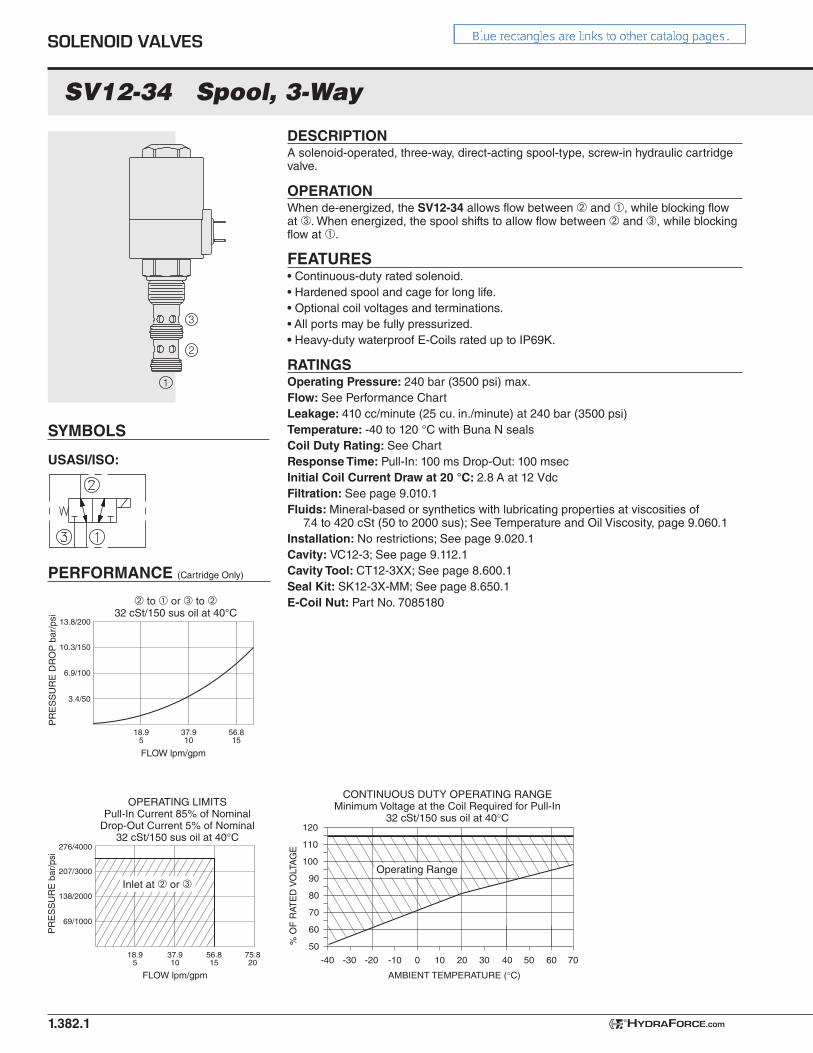
DESCRIPTIONA solenoid-operated, three-way, direct-acting spool-type, screw-in hydraulic cartridge valve.
OPERATIONWhen de-energized, the SV12-34 allows flow between ➁ and ➀, while blocking flow at ➂. When energized, the spool shifts to allow flow between ➁ and ➂, while blocking flow at ➀.
FEATURES• Continuous-duty rated solenoid.• Hardened spool and cage for long life.• Optional coil voltages and terminations.• All ports may be fully pressurized.• Heavy-duty waterproof E-Coils rated up to IP69K.
RATINGSOperating Pressure: 240 bar (3500 psi) max.Flow: See Performance ChartLeakage: 410 cc/minute (25 cu. in./minute) at 240 bar (3500 psi)Temperature: -40 to 120 °C with Buna N sealsCoil Duty Rating: See ChartResponse Time: Pull-In: 100 ms Drop-Out: 100 msecInitial Coil Current Draw at 20 °C: 2.8 A at 12 VdcFiltration: See page 9.010.1 Fluids: Mineral-based or synthetics with lubricating properties at viscosities of
7.4 to 420 cSt (50 to 2000 sus); See Temperature and Oil Viscosity, page 9.060.1Installation: No restrictions; See page 9.020.1Cavity: VC12-3; See page 9.112.1Cavity Tool: CT12-3XX; See page 8.600.1Seal Kit: SK12-3X-MM; See page 8.650.1E-Coil Nut: Part No. 7085180
USASI/ISO:
PERFORMANCE (Cartridge Only)
SYMBOLS
1.382.1
2
1
3
13.8/200
10.3/150
6.9/100
3.4/50
37.910
18.95
56.815
FLOW lpm/gpm
PR
ES
SU
RE
DR
OP
bar
/psi
� to � or � to �32 cSt/150 sus oil at 40°C
276/4000
207/3000
138/2000
69/1000
37.910
18.95
56.815
75.820
FLOW lpm/gpm
PR
ES
SU
RE
bar
/psi
OPERATING LIMITSPull-In Current 85% of Nominal
Drop-Out Current 5% of Nominal32 cSt/150 sus oil at 40°C
Inlet at � or �
110
120
60 7050403020100-20 -10-30-40
100
80
90
70
60
50% O
F R
ATE
D V
OLT
AG
E
AMBIENT TEMPERATURE (°C)
CONTINUOUS DUTY OPERATING RANGEMinimum Voltage at the Coil Required for Pull-In
32 cSt/150 sus oil at 40°C
Operating Range
SOLENOID VALVES
HYDRAFORCE.com®
SV12-34
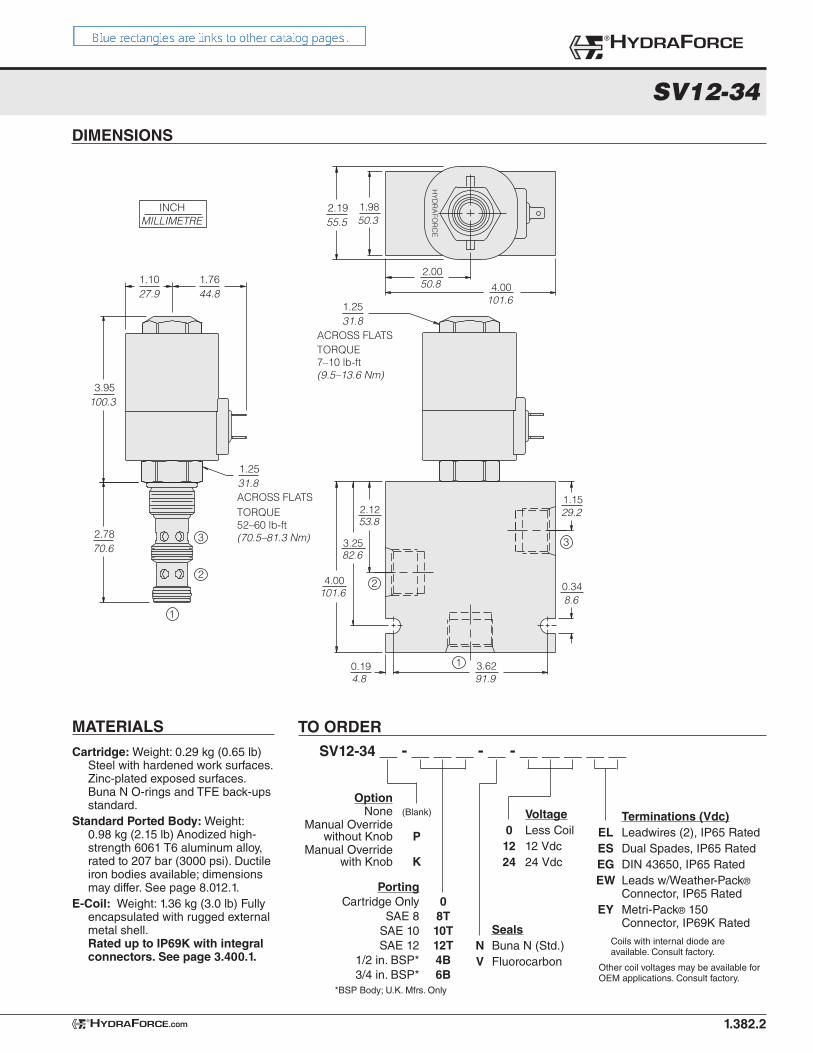
1.382.2
MILLIMETRE
1.1027.9
1.7644.8
1.25
ACROSS FLATS31.8
3.95100.3
2.7870.6
INCH
1.25
ACROSS FLATS31.8
2.19
HYD
RA
FOR
CE
55.5
53.8
82.6
101.6
29.2
8.6
91.94.8
101.6
50.8
50.3
1.15
3.620.19
4.00
3.25
2.12
4.002.00
1.98
0.342
1
3
2
3
1
TORQUE52–60 lb-ft(70.5–81.3 Nm)
TORQUE7–10 lb-ft(9.5–13.6 Nm)
TO ORDERSV12-34 __ - __ __ __ - __ - __ __ __ __ __
Porting Cartridge Only 0 SAE 8 8T SAE 10 10T SAE 12 12T 1/2 in. BSP* 4B 3/4 in. BSP* 6B*BSP Body; U.K. Mfrs. Only
Voltage 0 Less Coil 12 12 Vdc 24 24 Vdc
Terminations (Vdc) EL Leadwires (2), IP65 Rated ES Dual Spades, IP65 Rated EG DIN 43650, IP65 Rated EW Leads w/Weather-Pack® Connector, IP65 Rated EY Metri-Pack® 150 Connector, IP69K Rated Seals
N Buna N (Std.) V Fluorocarbon
Coils with internal diode are available. Consult factory.
Other coil voltages may be available for OEM applications. Consult factory.
®HYDRAFORCE
HYDRAFORCE.com®
Cartridge: Weight: 0.29 kg (0.65 lb) Steel with hardened work surfaces. Zinc-plated exposed surfaces. Buna N O-rings and TFE back-ups standard.
Standard Ported Body: Weight: 0.98 kg (2.15 lb) Anodized high-strength 6061 T6 aluminum alloy, rated to 207 bar (3000 psi). Ductile iron bodies available; dimensions may differ. See page 8.012.1.
E-Coil: Weight: 1.36 kg (3.0 lb) Fully encapsulated with rugged external metal shell. Rated up to IP69K with integral connectors. See page 3.400.1.
MATERIALS
Option None (Blank) Manual Override without Knob P Manual Override with Knob K
DIMENSIONS

Code
10T 12T 16T
6B8B
12TD 16TD
6BD8BD
Part No.
702224070222507022260
70225207022530
71550107155020
71550507155060
Material
Alum.Alum.Alum.
Alum.Alum.
Duct. IronDuct. IronDuct. IronDuct. Iron
Port 1
SAE 10SAE 12SAE 16
3/4" BSP1" BSP
SAE 12SAE 16
3/4" BSP1" BSP
Port 2
SAE 10SAE 12SAE 16
3/4" BSP1" BSP
SAE 12SAE 16
3/4" BSP1" BSP
Mfg. Loc.
U.S.U.S.U.S.
U.K.U.K.
U.S.U.S.
U.K.U.K.
HOUSINGS AND ACCESSORY PRODUCTS
Series 12 Valve Housings
8.012.1
SERIES 12 2-WAY HOUSINGS
MATERIAL
Aluminum
Aluminum
Ductile Iron
Ductile Iron
OPERATING PRESSURE
210 bar (3000 psi)
210 bar (3000 psi)
350 bar (5000 psi)
350 bar (5000 psi)
PORTS
SAE
BSP
SAE
BSP
MFG. LOCATION
U.S.
U.K.
U.S.
U.K.
HYDRAFORCE STANDARD VALVE HOUSINGS
HYDRAFORCE.com®
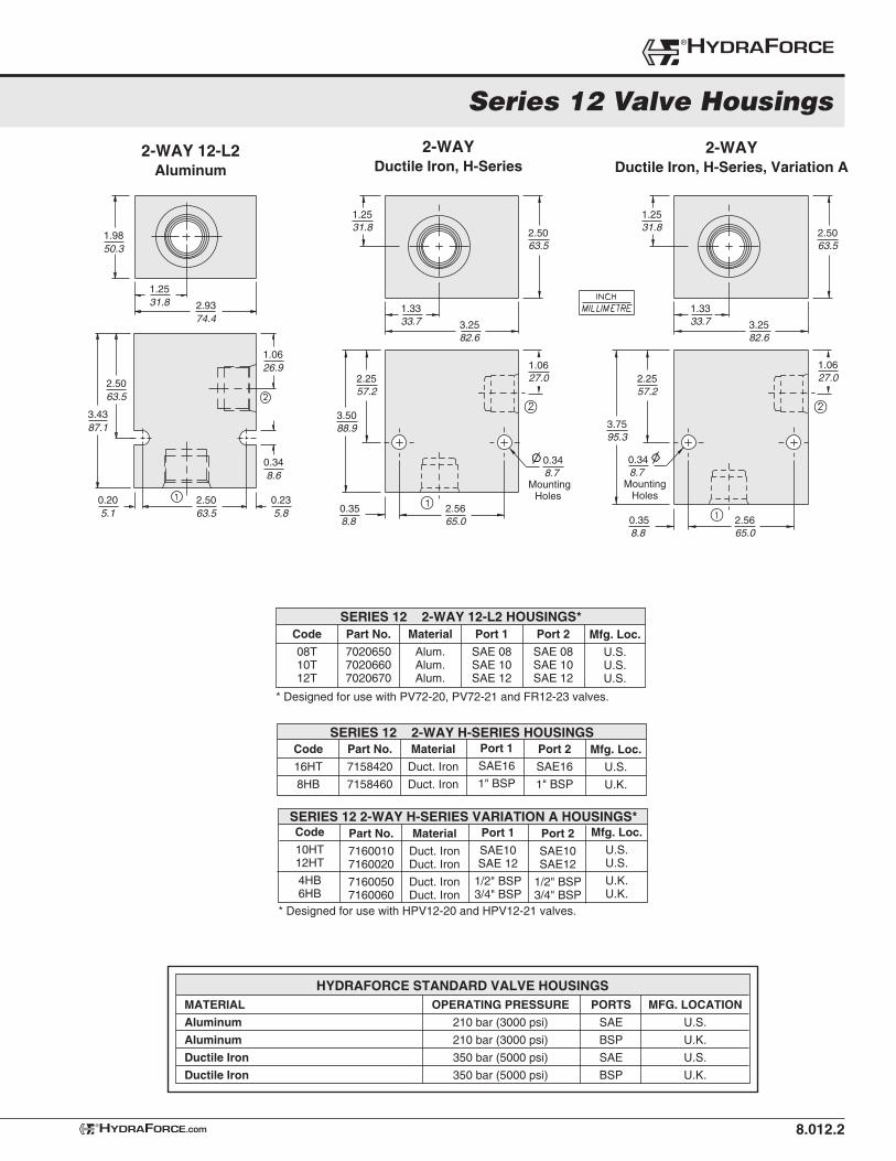
2-WAYAluminum
2-WAYDuctile Iron
SAE 12 Ported Housing shown
SAE 12 Ported Housing shown
2.0050.8
1.3333.7
3.2582.6
0.3448.74Thru
2 Places
2.2557.2
3.5088.9
1.0626.9
0.358.8
2.5665.0
SERIES 12 2-WAY H-SERIES VARIATION A HOUSINGS*
8.012.2
Series 12 Valve Housings
Code
08T 10T 12T
Part No.
702065070206607020670
Material
Alum.Alum.Alum.
Port 1
SAE 08SAE 10SAE 12
Port 2
SAE 08SAE 10SAE 12
Mfg. Loc.
U.S.U.S.U.S.
SERIES 12 2-WAY 12-L2 HOUSINGS*
* Designed for use with PV72-20, PV72-21 and FR12-23 valves.
®HYDRAFORCE
HYDRAFORCE.com®
2-WAY 12-L2Aluminum
1.2531.8
1.9850.3
2.9374.4
0.348.6
0.235.8
0.205.1
1.0626.9
2.5063.5
2.5063.5
3.4387.1
1.3333.7 3.25
82.6
1.2531.8 2.50
63.5
1.0627.02.25
57.2
3.75
MountingHoles
95.3
2.5665.0
0.358.8
0.348.7
1.3333.7 3.25
82.6
1.2531.8 2.50
63.5
1.0627.02.25
57.2
3.50
MountingHoles
88.9
2.5665.0
0.358.8
0.348.7
MATERIAL
Aluminum
Aluminum
Ductile Iron
Ductile Iron
OPERATING PRESSURE
210 bar (3000 psi)
210 bar (3000 psi)
350 bar (5000 psi)
350 bar (5000 psi)
PORTS
SAE
BSP
SAE
BSP
MFG. LOCATION
U.S.
U.K.
U.S.
U.K.
HYDRAFORCE STANDARD VALVE HOUSINGS
2-WAYDuctile Iron, H-Series
Code
16HT
8HB
Part No.
7158420
7158460
Material
Duct. Iron
Duct. Iron
Port 1
SAE16
1" BSP
Port 2
SAE16
1" BSP
Mfg. Loc.
U.S.
U.K.
SERIES 12 2-WAY H-SERIES HOUSINGS
Part No.
71600107160020
71600507160060
Material
Duct. IronDuct. Iron
Duct. IronDuct. Iron
Port 1
SAE10SAE 12
1/2" BSP3/4" BSP
Port 2
SAE10SAE12
1/2" BSP3/4" BSP
Mfg. Loc.
U.S.U.S.
U.K.U.K.
Code
10HT 12HT
4HB6HB
2-WAYDuctile Iron, H-Series, Variation A
* Designed for use with HPV12-20 and HPV12-21 valves.
8.012.3
HOUSINGS AND ACCESSORY PRODUCTS
Series 12 Valve Housings
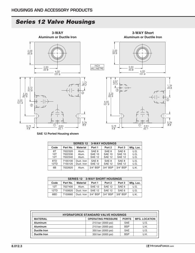
SERIES 12 3-WAY SHORT HOUSINGS
HYDRAFORCE.com®
Code
8T 10T 12T
8TD12TD
6B
Part No.
702232070223307022340
71551007155120
7022620
Material
Alum.Alum.Alum.
Duct. IronDuct. Iron
Alum.
Port 1
SAE 8SAE 10SAE 12
SAE 8SAE 12
3/4" BSP
Port 2
SAE 8SAE 10SAE 12
SAE 8SAE 12
3/4" BSP
Mfg. Loc.
U.S.U.S.U.S.
U.S.U.S.
U.K.
Port 3
SAE 8SAE 10SAE 12
SAE 8SAE 12
3/4" BSP
SERIES 12 3-WAY HOUSINGS
3-WAYAluminum or Ductile Iron
3-WAY ShortAluminum or Ductile Iron
SAE 12 Ported Housing shown
MATERIAL
Aluminum
Aluminum
Ductile Iron
Ductile Iron
OPERATING PRESSURE
210 bar (3000 psi)
210 bar (3000 psi)
350 bar (5000 psi)
350 bar (5000 psi)
PORTS
SAE
BSP
SAE
BSP
MFG. LOCATION
U.S.
U.K.
U.S.
U.K.
HYDRAFORCE STANDARD VALVE HOUSINGS
Code
12T
12TD
6BD
Part No.
7027400
7150620
7150660
Material
Alum.
Duct. Iron
Duct. Iron
Port 1
SAE 12
SAE 12
3/4" BSP
Port 2
SAE 12
SAE 12
3/4" BSP
Mfg. Loc.
U.S.
U.S.
U.K.
Port 3
SAE 6
SAE 6
3/8" BSP
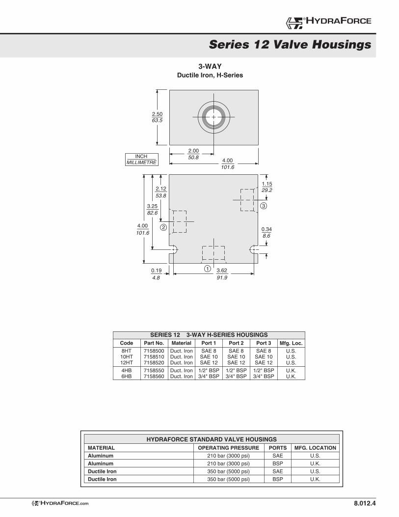
3-WAYDuctile Iron, H-Series
INCHMILLIMETRE
53.8
82.6
101.6
29.2
8.6
91.94.8
101.6
50.8
63.5
1.15
3.620.19
4.00
3.25
2.12
4.00
2.00
2.50
0.342
3
1
Code
8HT 10HT 12HT
4HB6HB
Part No.
715850071585107158520
71585507158560
Material
Duct. IronDuct. IronDuct. Iron
Duct. IronDuct. Iron
Port 1
SAE 8SAE 10SAE 12
1/2" BSP3/4" BSP
Port 2
SAE 8SAE 10SAE 12
1/2" BSP3/4" BSP
Mfg. Loc.
U.S.U.S.U.S.
U.K.U.K.
Port 3
SAE 8SAE 10SAE 12
1/2" BSP3/4" BSP
SERIES 12 3-WAY H-SERIES HOUSINGS
MATERIAL
Aluminum
Aluminum
Ductile Iron
Ductile Iron
OPERATING PRESSURE
210 bar (3000 psi)
210 bar (3000 psi)
350 bar (5000 psi)
350 bar (5000 psi)
PORTS
SAE
BSP
SAE
BSP
MFG. LOCATION
U.S.
U.K.
U.S.
U.K.
HYDRAFORCE STANDARD VALVE HOUSINGS
HYDRAFORCE.com® 8.012.4
Series 12 Valve Housings
®HYDRAFORCE
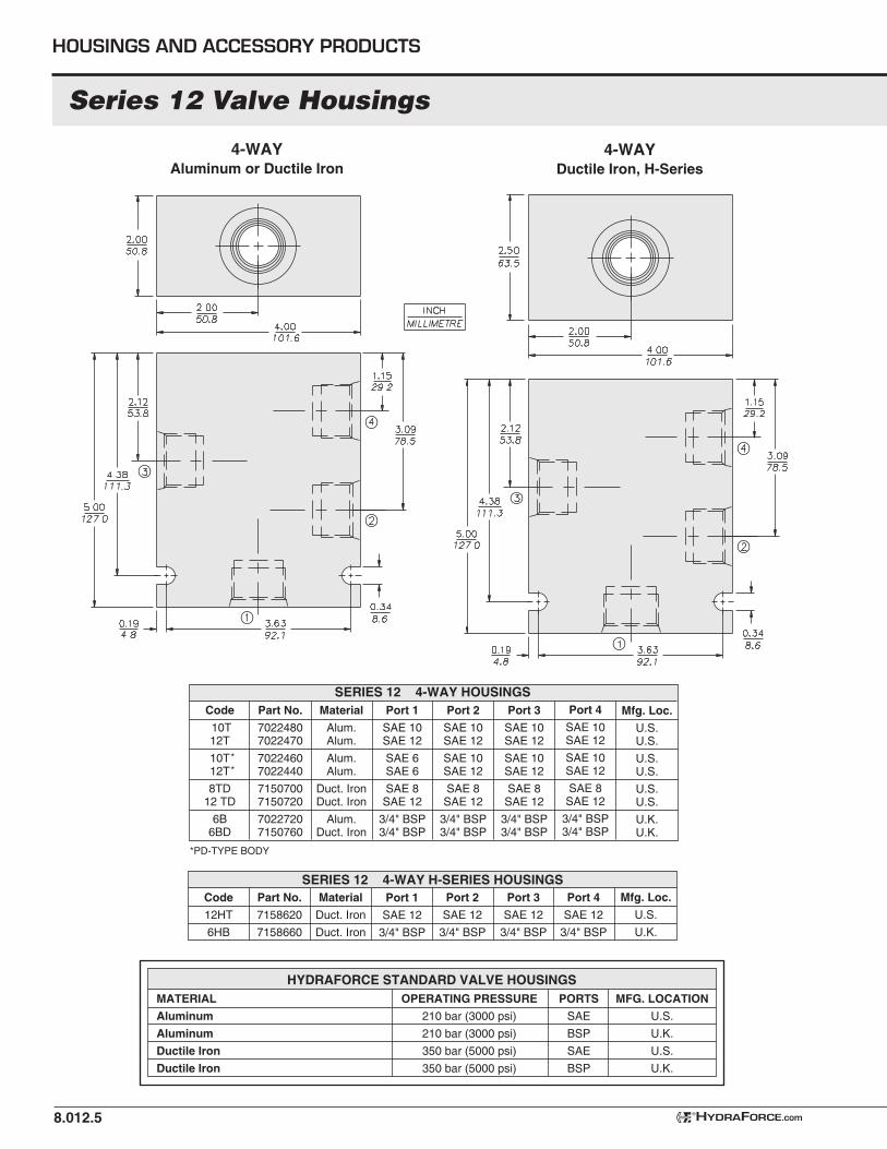
Code
10T 12T
10T12T
8TD12 TD
6B6BD
Part No.
70224807022470
70224607022440
71507007150720
70227207150760
Material
Alum.Alum.
Alum.Alum.
Duct. IronDuct. Iron
Alum.Duct. Iron
Port 1
SAE 10SAE 12
SAE 6SAE 6
SAE 8SAE 12
3/4" BSP3/4" BSP
Port 2
SAE 10SAE 12
SAE 10SAE 12
SAE 8SAE 12
3/4" BSP3/4" BSP
Mfg. Loc.
U.S.U.S.
U.S.U.S.
U.S.U.S.
U.K.U.K.
Port 3
SAE 10SAE 12
SAE 10SAE 12
SAE 8SAE 12
3/4" BSP3/4" BSP
Port 4
SAE 10SAE 12
SAE 10SAE 12
SAE 8SAE 12
3/4" BSP3/4" BSP
8.012.5
Series 12 Valve Housings
*PD-TYPE BODY
SERIES 12 4-WAY HOUSINGS
**
HYDRAFORCE.com®
4-WAYAluminum or Ductile Iron
MATERIAL
Aluminum
Aluminum
Ductile Iron
Ductile Iron
OPERATING PRESSURE
210 bar (3000 psi)
210 bar (3000 psi)
350 bar (5000 psi)
350 bar (5000 psi)
PORTS
SAE
BSP
SAE
BSP
MFG. LOCATION
U.S.
U.K.
U.S.
U.K.
HYDRAFORCE STANDARD VALVE HOUSINGS
HOUSINGS AND ACCESSORY PRODUCTS
Code
12HT
6HB
Part No.
7158620
7158660
Material
Duct. Iron
Duct. Iron
Port 1
SAE 12
3/4" BSP
Port 2
SAE 12
3/4" BSP
Mfg. Loc.
U.S.
U.K.
Port 4
SAE 12
3/4" BSP
Port 3
SAE 12
3/4" BSP
SERIES 12 4-WAY H-SERIES HOUSINGS
4-WAYDuctile Iron, H-Series
Code
10T 12T
12TD
6BD
Part No.
70224507022430
7150820
7150860
Material
Alum.Alum.
Duct. Iron
Duct. Iron
Port 1
——
—
—
Port 2
SAE 10SAE 12
SAE 12
3/4" BSP
Mfg. Loc.
U.S.U.S.
U.S.
U.K.
Port 4
SAE 10SAE 12
SAE 12
3/4" BSP
Port 3
SAE 10SAE 12
SAE 12
3/4" BSP
8.012.6HYDRAFORCE.com®
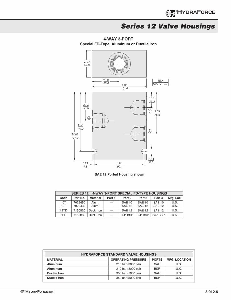
SERIES 12 4-WAY 3-PORT SPECIAL FD-TYPE HOUSINGS
4-WAY 3-PORTSpecial FD-Type, Aluminum or Ductile Iron
SAE 12 Ported Housing shown
MATERIAL
Aluminum
Aluminum
Ductile Iron
Ductile Iron
OPERATING PRESSURE
210 bar (3000 psi)
210 bar (3000 psi)
350 bar (5000 psi)
350 bar (5000 psi)
PORTS
SAE
BSP
SAE
BSP
MFG. LOCATION
U.S.
U.K.
U.S.
U.K.
HYDRAFORCE STANDARD VALVE HOUSINGS
Series 12 Valve Housings
®HYDRAFORCE
8.012.7
Series 12 Valve Housings
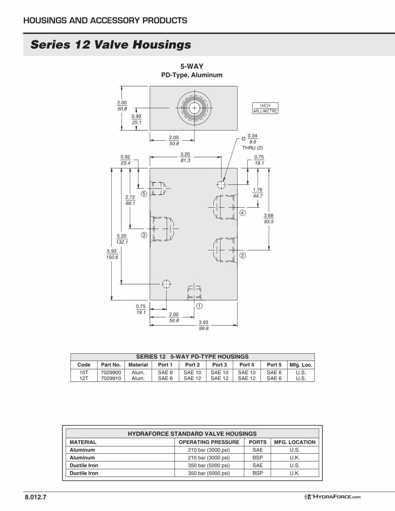
Code
10T 12T
Part No.
70299007029910
Material
Alum.Alum.
Port 1
SAE 6SAE 6
Port 2
SAE 10SAE 12
Mfg. Loc.
U.S.U.S.
SERIES 12 5-WAY PD-TYPE HOUSINGSPort 3
SAE 10SAE 12
Port 4
SAE 10SAE 12
Port 5
SAE 6SAE 6
5-WAYPD-Type, Aluminum
0.9925.1
3.2081.3
0.7519.1
1.7644.7
3.6893.5
3.9399.8
2.0050.8
0.7519.1
0.348.6
Ø
THRU (2)
5.93150.6
5.20132.1
2.7269.1
0.9223.4
2.0050.8
2.0050.8
2
3
1
4
5
MATERIAL
Aluminum
Aluminum
Ductile Iron
Ductile Iron
OPERATING PRESSURE
210 bar (3000 psi)
210 bar (3000 psi)
350 bar (5000 psi)
350 bar (5000 psi)
PORTS
SAE
BSP
SAE
BSP
MFG. LOCATION
U.S.
U.K.
U.S.
U.K.
HYDRAFORCE STANDARD VALVE HOUSINGS
HOUSINGS AND ACCESSORY PRODUCTS
HYDRAFORCE.com®
8.012.8
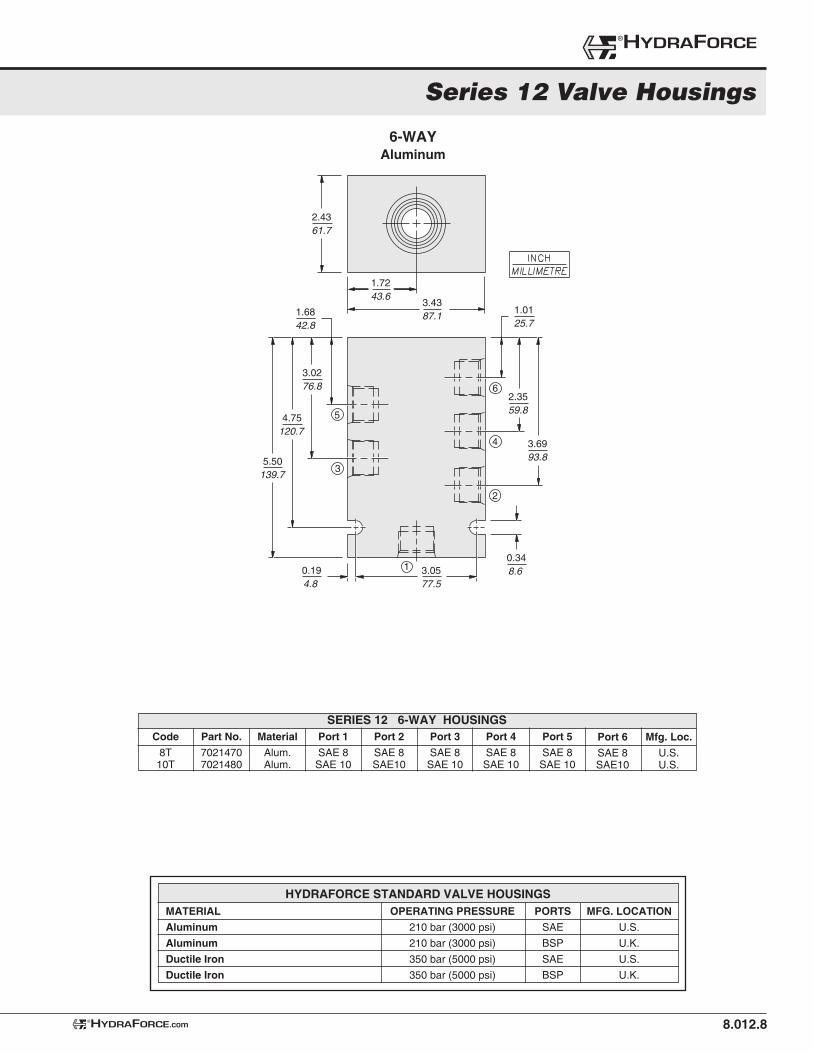
Code
8T10T
Part No.
70214707021480
Material
Alum.Alum.
Port 1
SAE 8SAE 10
Port 2
SAE 8SAE10
Port 6
SAE 8SAE10
SERIES 12 6-WAY HOUSINGSPort 3
SAE 8SAE 10
Port 4
SAE 8SAE 10
Port 5
SAE 8SAE 10
Mfg. Loc.
U.S.U.S.
6-WAYAluminum
1
1.7243.6
2.4361.7
3.4387.1
2
3
4
5
6
1.0125.7
2.3559.8
3.6993.8
0.348.60.19
4.8
1.6842.8
3.0276.8
4.75120.7
5.50139.7
3.0577.5
MATERIAL
Aluminum
Aluminum
Ductile Iron
Ductile Iron
OPERATING PRESSURE
210 bar (3000 psi)
210 bar (3000 psi)
350 bar (5000 psi)
350 bar (5000 psi)
PORTS
SAE
BSP
SAE
BSP
MFG. LOCATION
U.S.
U.K.
U.S.
U.K.
HYDRAFORCE STANDARD VALVE HOUSINGS
HYDRAFORCE.com®
Series 12 Valve Housings
®HYDRAFORCE
8.012.9
Series 12 Valve Housings
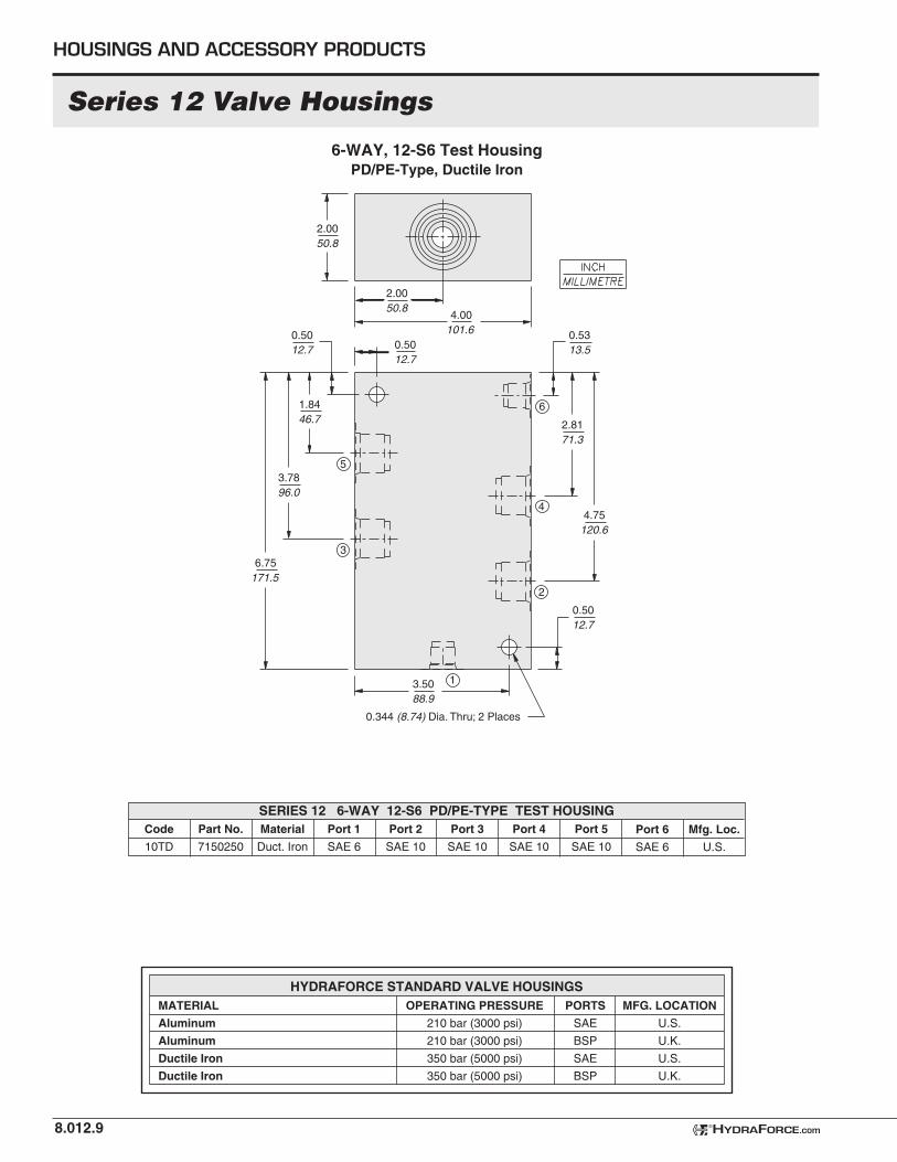
SERIES 12 6-WAY 12-S6 PD/PE-TYPE TEST HOUSING
HYDRAFORCE.com®
6-WAY, 12-S6 Test HousingPD/PE-Type, Ductile Iron
0.5012.7
13.5088.9
2
3
4
5
6
2.0050.8
2.0050.8
0.5012.7
1.8446.7
4.00101.6 0.53
13.5
0.50
0.344 (8.74) Dia. Thru; 2 Places
12.7
2.8171.3
4.75120.6
3.7896.0
6.75171.5
MATERIAL
Aluminum
Aluminum
Ductile Iron
Ductile Iron
OPERATING PRESSURE
210 bar (3000 psi)
210 bar (3000 psi)
350 bar (5000 psi)
350 bar (5000 psi)
PORTS
SAE
BSP
SAE
BSP
MFG. LOCATION
U.S.
U.K.
U.S.
U.K.
HYDRAFORCE STANDARD VALVE HOUSINGS
Code
10TD
Part No.
7150250
Port 1
SAE 6
Port 2
SAE 10
Port 6
SAE 6
Port 3
SAE 10
Port 4
SAE 10
Port 5
SAE 10
Mfg. Loc.
U.S.
Material
Duct. Iron
HOUSINGS AND ACCESSORY PRODUCTS
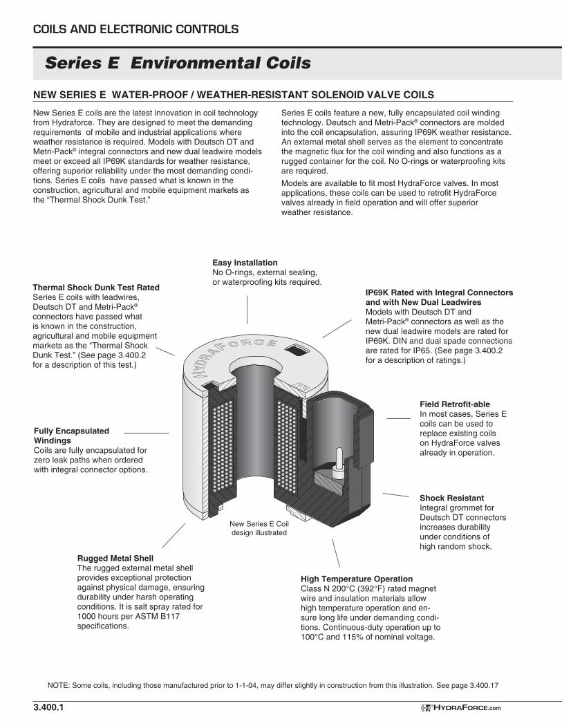
Series E Environmental Coils
NEW SERIES E WATER-PROOF / WEATHER-RESISTANT SOLENOID VALVE COILS
3.400.1
New Series E coils are the latest innovation in coil technology from Hydraforce. They are designed to meet the demanding requirements of mobile and industrial applications where weather resistance is required. Models with Deutsch DT and Metri-Pack® integral connectors and new dual leadwire models meet or exceed all IP69K standards for weather resistance, offering superior reliability under the most demanding condi-tions. Series E coils have passed what is known in the construction, agricultural and mobile equipment markets as the “Thermal Shock Dunk Test.”
IP69K Rated with Integral Connectors and with New Dual LeadwiresModels with Deutsch DT and Metri-Pack® connectors as well as the new dual leadwire models are rated for IP69K. DIN and dual spade connections are rated for IP65. (See page 3.400.2 for a description of ratings.)
Fully Encapsulated WindingsCoils are fully encapsulated for zero leak paths when ordered with integral connector options.
High Temperature OperationClass N 200°C (392°F) rated magnet wire and insulation materials allow high temperature operation and en-sure long life under demanding condi-tions. Continuous-duty operation up to 100°C and 115% of nominal voltage.
Field Retrofit-ableIn most cases, Series E coils can be used to replace existing coils on HydraForce valves already in operation.
Easy InstallationNo O-rings, external sealing, or waterproofing kits required.
Thermal Shock Dunk Test RatedSeries E coils with leadwires, Deutsch DT and Metri-Pack® connectors have passed what is known in the construction, agricultural and mobile equipment markets as the “Thermal Shock Dunk Test.” (See page 3.400.2 for a description of this test.)
Rugged Metal ShellThe rugged external metal shell provides exceptional protection against physical damage, ensuring durability under harsh operating conditions. It is salt spray rated for 1000 hours per ASTM B117 specifications.
NOTE: Some coils, including those manufactured prior to 1-1-04, may differ slightly in construction from this illustration. See page 3.400.17
COILS AND ELECTRONIC CONTROLS
Series E coils feature a new, fully encapsulated coil winding technology. Deutsch and Metri-Pack® connectors are molded into the coil encapsulation, assuring IP69K weather resistance. An external metal shell serves as the element to concentrate the magnetic flux for the coil winding and also functions as a rugged container for the coil. No O-rings or waterproofing kits are required.
Models are available to fit most HydraForce valves. In most applications, these coils can be used to retrofit HydraForce valves already in field operation and will offer superior weather resistance.
New Series E Coil design illustrated
Shock ResistantIntegral grommet for Deutsch DT connectors increases durability under conditions of high random shock.
HYDRAFORCE.com®
3.400.2
Series E Environmental Coils
IMPROVING DURABILITY TO ASSURE LONG LIFE IN THE HARSHEST ENVIRONMENTS
HydraForce has made design changes to the industry-lead-ing environmentally-hardened Series E coils. The new design provides longer life under high-temperature conditions, as well as easier and more convenient interchange with our Series D standard-duty coils.
The Story Behind the RatingsTo appreciate the performance of the new Series E coils, it is helpful to have a working knowledge of the testing conducted to assure coil life in the harshest environments. Many OEMs request a coil that is IP67 or IP69 rated. These ratings do not address the issue of the effect of high temperatures on coil life and operation. Therefore they are of limited value in evaluat-ing the suitability of a coil for use in typical mobile equipment applications.
Why temperature matters: When a coil is heated, the air inside the coil expands, creating internal pressure, causing the heated air to attempt to exit the coil. If the coil is then submerged in cold water, the air within the coil cools and contracts, drawing water into the coil through any seams or voids in the coil encapsulant. Eventually the water will fi nd its way into the winding area, causing the coil winding to corrode or short-circuit, resulting in coil failure.
IP ratings are international specifi cations for electrical equip-ment which defi ne various levels of protection against failure resulting from contamination by water or other foreign sub-stances. The IP67 rating is based on submerging the coil in one meter of water for 30 minutes. The coil is then inspected for evidence of water infi ltration. The IP67 specifi cation loosely states that “ingress of water in quantities causing harmful effect shall not occur.” The exact meaning of the phrase “harmful effect” is not precisely defi ned, and is therefore open to some interpretation. In this test, the coil is not subjected to high tem-peratures, so the effects of thermal stress are not considered.
The IP69 rating, which is currently only part of the DIN version of this specifi cation, fi rst requires that the coil pass the test for IP67 as described above. Beyond that, the coil and its integral electrical connector are subjected to a rigorous high-pressure water spray. The water is mixed with detergent, is held at a temperature of 80°C., and is sprayed at the coil from a distance of 100 mm (4 inches) at a pressure of 100 bar (1450 psi). Again, the specifi cation does not precisely defi ne the amount of water ingress that would be considered unacceptable.
HydraForce RatingsWorking with major mobile equipment OEMs, HydraForce has developed even more rigorous tests that are designed to assure that our coils will perform reliably under the harshest real-world application conditions. Both our original and our new Series E coils meet or exceed the requirements of what is known as the “Thermal Shock Dunk Test.” In this test the coil is thermally “soaked” for two hours in an ambient temperature of 100°C. The coil is then immersed immediately in a 0°C salt-water bath for two hours. This procedure is repeated ten times. The coil is then inspected for water ingress. By Hydraforce’s standards, the coil is considered to have passed this test if there is NO detectable water ingress, as determined by visual inspection and a “high pot” test. This standard requires a totally sealed coil that is impervious to moisture infi ltration, even under widely varying ambient thermal conditions.
The new Series E coils can now withstand at least 10 cycles of the “Thermal Shock Dunk Test.”
In addition to the requirements of the industry-recognized, “Thermal Shock Dunk Test,” described above, HydraForce further tests these coils for durability against failure due to vibration, as well as against failure due to the application of voltage above the coil’s standard duty rating while it is simulta-neously subjected to continually varying ambient temperatures.
Beyond enhancing the durability of the coils, we have decreased the wattage by approximately 10%. This reduces the power consumption and also allows the operating temperature range to be extended. The new design also improves the ease and convenience of interchanging these coils with HydraForce’s Series D (standard duty) coils, the original Series E coils, as well as the older “W-style” waterproof option. The new Series E coils use the same retaining nuts as the Series D coils, simplifying interchangeability, inventory and assembly requirements and procedures.
See page 3.400.17 for detailed information describing the differences between the original Series E coils and the new Series E coils, including part number cross-references for the coils, the retaining nuts, and the spacers used on the dual-solenoid valves.
®HYDRAFORCE
HYDRAFORCE.com®
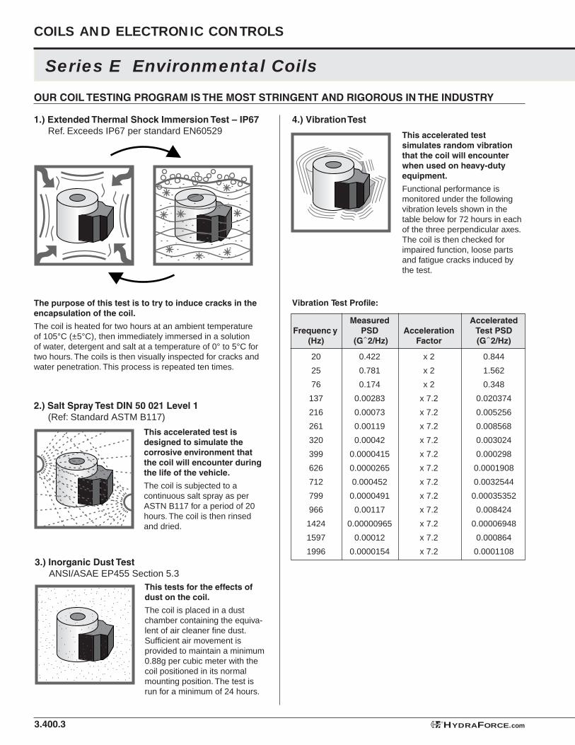
Series E Environmental Coils
OUR COIL TESTING PROGRAM IS THE MOST STRINGENT AND RIGOROUS IN THE INDUSTRY
3.400.3
COILS AND ELECTRONIC CONTROLS
1.) Extended Thermal Shock Immersion Test – IP67 Ref. Exceeds IP67 per standard EN60529
The purpose of this test is to try to induce cracks in the encapsulation of the coil.
The coil is heated for two hours at an ambient temperature of 105°C (±5°C), then immediately immersed in a solution of water, detergent and salt at a temperature of 0° to 5°C for two hours. The coils is then visually inspected for cracks and water penetration. This process is repeated ten times.
2.) Salt Spray Test DIN 50 021 Level 1 (Ref: Standard ASTM B117)
This accelerated test is designed to simulate the corrosive environment that the coil will encounter during the life of the vehicle.
The coil is subjected to a continuous salt spray as per ASTN B117 for a period of 20 hours. The coil is then rinsed and dried.
3.) Inorganic Dust Test ANSI/ASAE EP455 Section 5.3
This tests for the effects of dust on the coil.
The coil is placed in a dust chamber containing the equiva-lent of air cleaner fi ne dust. Suffi cient air movement is provided to maintain a minimum 0.88g per cubic meter with the coil positioned in its normal mounting position. The test is run for a minimum of 24 hours.
This accelerated test simulates random vibration that the coil will encounter when used on heavy-duty equipment.
Functional performance is monitored under the following vibration levels shown in the table below for 72 hours in each of the three perpendicular axes. The coil is then checked for impaired function, loose parts and fatigue cracks induced by the test.
4.) Vibration Test
Measured Accelerated Frequenc y PSD Acceleration Test PSD (Hz) (G 2/Hz) Factor (G 2/Hz)
20 0.422 x 2 0.844
25 0.781 x 2 1.562
76 0.174 x 2 0.348
137 0.00283 x 7.2 0.020374
216 0.00073 x 7.2 0.005256
261 0.00119 x 7.2 0.008568
320 0.00042 x 7.2 0.003024
399 0.0000415 x 7.2 0.000298
626 0.0000265 x 7.2 0.0001908
712 0.000452 x 7.2 0.0032544
799 0.0000491 x 7.2 0.00035352
966 0.00117 x 7.2 0.008424
1424 0.00000965 x 7.2 0.00006948
1597 0.00012 x 7.2 0.000864
1996 0.0000154 x 7.2 0.0001108
Vibration Test Profi le:
HYDRAFORCE.com®
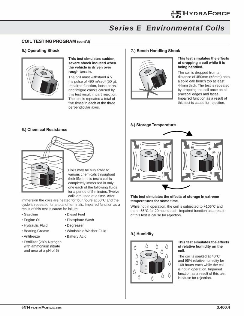
3.400.4
Series E Environmental Coils
COIL TESTING PROGRAM (cont’d)
5.) Operating Shock
This test simulates sudden, severe shock induced when the vehicle is driven over rough terrain.
The coil must withstand a 5 ms pulse of 490 m/sec2 (50 g). Impaired function, loose parts, and fatigue cracks caused by this test result in part rejection. The test is repeated a total of fi ve times in each of the three perpendicular axes.
Coils may be subjected to various chemicals throughout their life. In this test a coil is completely immersed in only one each of the following fl uids for a period of 5 minutes. Twelve coils are used at a time. After
immersion the coils are heated for four hours at 50°C and the cycle is repeated for a total of ten trials. Impaired function as a result of this test is cause for failure.
• Gasoline • Diesel Fuel
• Engine Oil • Phosphate Wash
• Hydraulic Fluid • Degreaser
• Bearing Grease • Windshield Washer Fluid
• Antifreeze • Battery Acid
• Fertilizer (28% Nitrogen with ammonium nitrate and urea at a pH of 5)
6.) Chemical Resistance
7.) Bench Handling Shock
This test simulates the effects of dropping a coil while it is being handled.
The coil is dropped from a distance of 450mm (±5mm) onto a solid oak bench top at least 44mm thick. The test is repeated by dropping the coil once on all practical edges and faces. Impaired function as a result of this test is cause for rejection.
8.) Storage Temperature
This test simulates the effects of storage in extreme temperatures for some time.
While not in operation, the coil is subjected to +105°C and then –55°C for 20 hours each. Impaired function as a result of this test is cause for rejection.
9.) Humidity
This test simulates the effects of relative humidity on the coil.
The coil is soaked at 40°C and 95% relative humidity for 168 hours each while the coil is not in operation. Impaired function as a result of this test is cause for rejection.
®HYDRAFORCE
HYDRAFORCE.com®
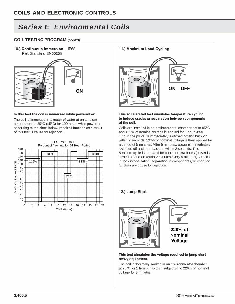
Series E Environmental Coils
3.400.5
COILS AND ELECTRONIC CONTROLS
COIL TESTING PROGRAM (cont’d)
10.) Continuous Immersion – IP68 Ref. Standard EN60529
In this test the coil is immersed while powered on.
The coil is immersed in 1 meter of water at an ambient temperature of 25°C (±5°C) for 120 hours while powered according to the chart below. Impaired function as a result of this test is cause for rejection.
ON
120110
90
130140
20 22 24181614121084 620
100
60
8070
50
30
10
40
20
0
% o
f NO
MIN
AL
VO
LTA
GE
TIME (Hours)
TEST VOLTAGE Percent of Nominal for 24-Hour Period
113% 113%
133% 133%
75%
ON – OFF
11.) Maximum Load Cycling
This accelerated test simulates temperature cycling to induce cracks or separation between components of the coil.
Coils are installed in an environmental chamber set to 85°C and 133% of nominal voltage is applied for 1 hour. After 1 hour, the power is immediately switched off and back on within 2 seconds. 133% of nominal voltage is then applied for a period of 5 minutes. After 5 minutes, power is immediately switched off and then back on within 2 seconds. This 5-minute cycle is repeated for a total of 168 hours (power is turned off and on within 2 minutes every 5 minutes). Cracks in the encapsulation, separation in components, or impaired function are cause for rejection.
220% ofNominalVoltage
12.) Jump Start
This test simulates the voltage required to jump start heavy equipment.
The coil is thermally soaked in an environmental chamber at 70°C for 2 hours. It is then subjected to 220% of nominal voltage for 5 minutes.
HYDRAFORCE.com®
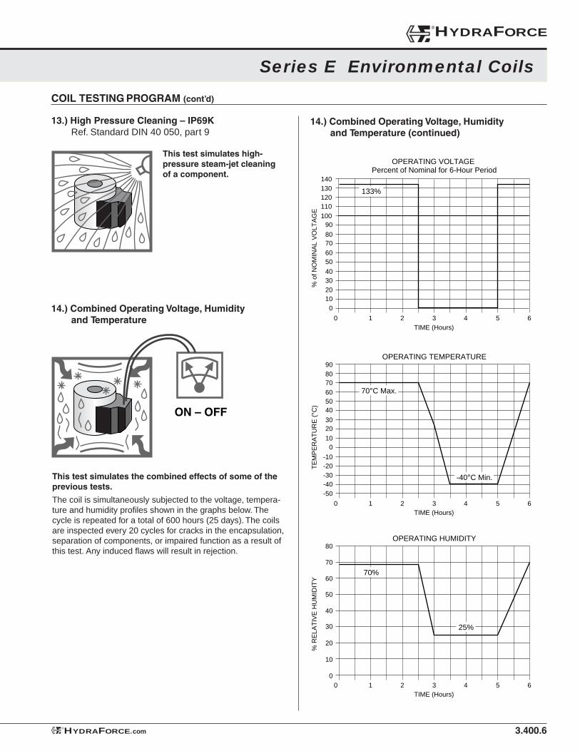
3.400.6
Series E Environmental Coils
COIL TESTING PROGRAM (cont’d)
13.) High Pressure Cleaning – IP69K Ref. Standard DIN 40 050, part 9
This test simulates high-pressure steam-jet cleaning of a component.
14.) Combined Operating Voltage, Humidity and Temperature
This test simulates the combined effects of some of the previous tests.
The coil is simultaneously subjected to the voltage, tempera-ture and humidity profi les shown in the graphs below. The cycle is repeated for a total of 600 hours (25 days). The coils are inspected every 20 cycles for cracks in the encapsulation, separation of components, or impaired function as a result of this test. Any induced fl aws will result in rejection.
ON – OFF
120110
90
130140
5 6431 20
100
60
8070
50
30
10
40
20
0%
of N
OM
INA
L V
OLT
AG
E
TIME (Hours)
OPERATING VOLTAGE Percent of Nominal for 6-Hour Period
133%
405060708090
5 6431 20
10
3020
0
-20
-40-50
-10
-30
TE
MP
ER
AT
UR
E (
°C)
TIME (Hours)
OPERATING TEMPERATURE
70°C Max.
-40°C Min.
40
50
60
70
80
5 6431 20
10
30
20
0
% R
ELA
TIV
E H
UM
IDIT
Y
TIME (Hours)
OPERATING HUMIDITY
70%
25%
14.) Combined Operating Voltage, Humidity and Temperature (continued)
®HYDRAFORCE
HYDRAFORCE.com®
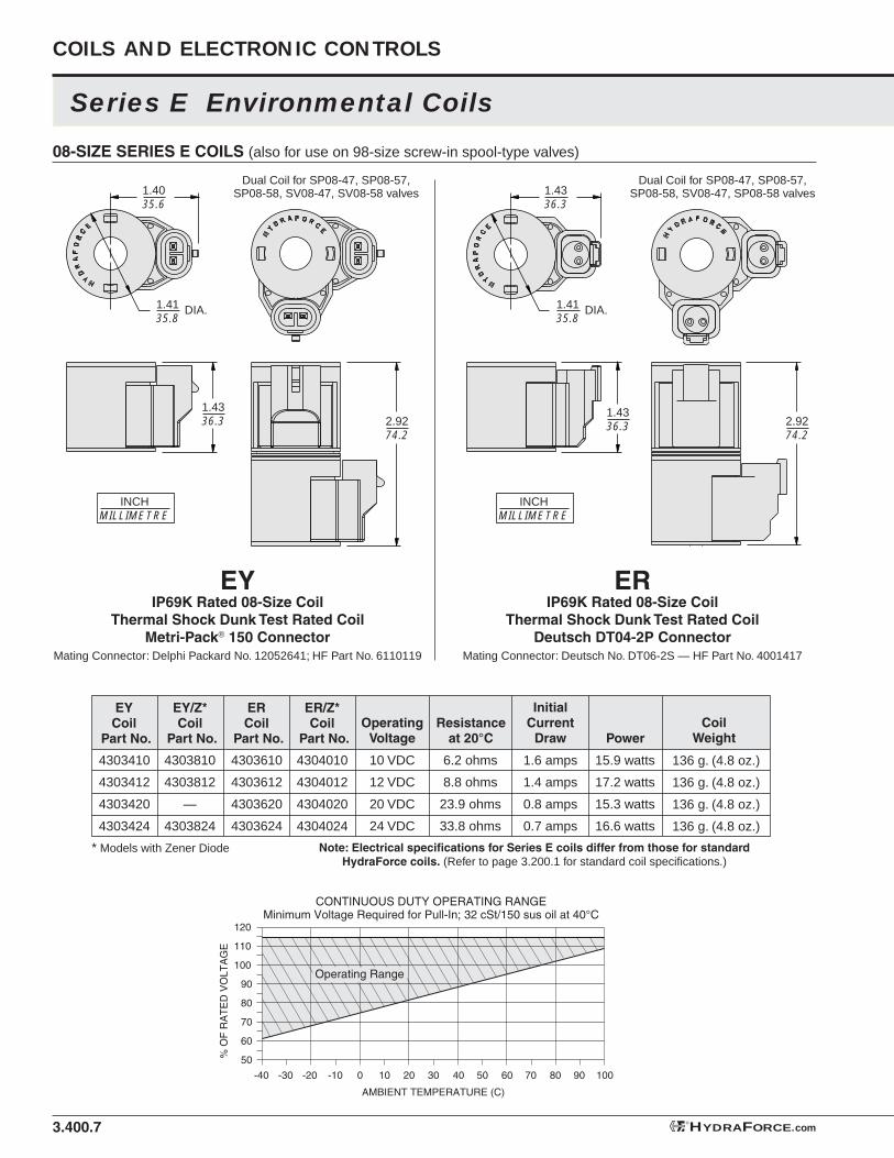
1.4135.8
1.4035.6
1.4336.3
INCHMILLIMETRE
1.4336.3
DIA. 1.4135.8
1.4336.3
DIA.
2.9274.2
2.9274.2
INCHMILLIMETRE
3.400.7
110
120
60 70 80 90 10050403020100-20 -10-30-40
100
80
90
70
60
50% O
F R
AT
ED
VO
LTA
GE
AMBIENT TEMPERATURE (C)
CONTINUOUS DUTY OPERATING RANGEMinimum Voltage Required for Pull-In; 32 cSt/150 sus oil at 40°C
Operating Range
Series E Environmental Coils
COILS AND ELECTRONIC CONTROLS
ERIP69K Rated 08-Size Coil
Thermal Shock Dunk Test Rated CoilDeutsch DT04-2P Connector
Mating Connector: Deutsch No. DT06-2S — HF Part No. 4001417
EYIP69K Rated 08-Size Coil
Thermal Shock Dunk Test Rated CoilMetri-Pack® 150 Connector
Mating Connector: Delphi Packard No. 12052641; HF Part No. 6110119
HYDRAFORCE.com®
Dual Coil for SP08-47, SP08-57, SP08-58, SV08-47, SV08-58 valves
Dual Coil for SP08-47, SP08-57, SP08-58, SV08-47, SP08-58 valves
Note: Electrical specifi cations for Series E coils differ from those for standard HydraForce coils. (Refer to page 3.200.1 for standard coil specifi cations.)
CoilWeight
OperatingVoltage
10 VDC
12 VDC
20 VDC
24 VDC
Resistance at 20°C
6.2 ohms
8.8 ohms
23.9 ohms
33.8 ohms
InitialCurrent
Draw
1.6 amps
1.4 amps
0.8 amps
0.7 amps
Power
15.9 watts
17.2 watts
15.3 watts
16.6 watts
ER/Z*Coil
Part No.
ERCoil
Part No.
EY/Z*Coil
Part No.
EYCoil
Part No.
* Models with Zener Diode
4303610
4303612
4303620
4303624
4303810
4303812
—
4303824
4303410
4303412
4303420
4303424
4304010
4304012
4304020
4304024
136 g. (4.8 oz.)
136 g. (4.8 oz.)
136 g. (4.8 oz.)
136 g. (4.8 oz.)
08-SIZE SERIES E COILS (also for use on 98-size screw-in spool-type valves)
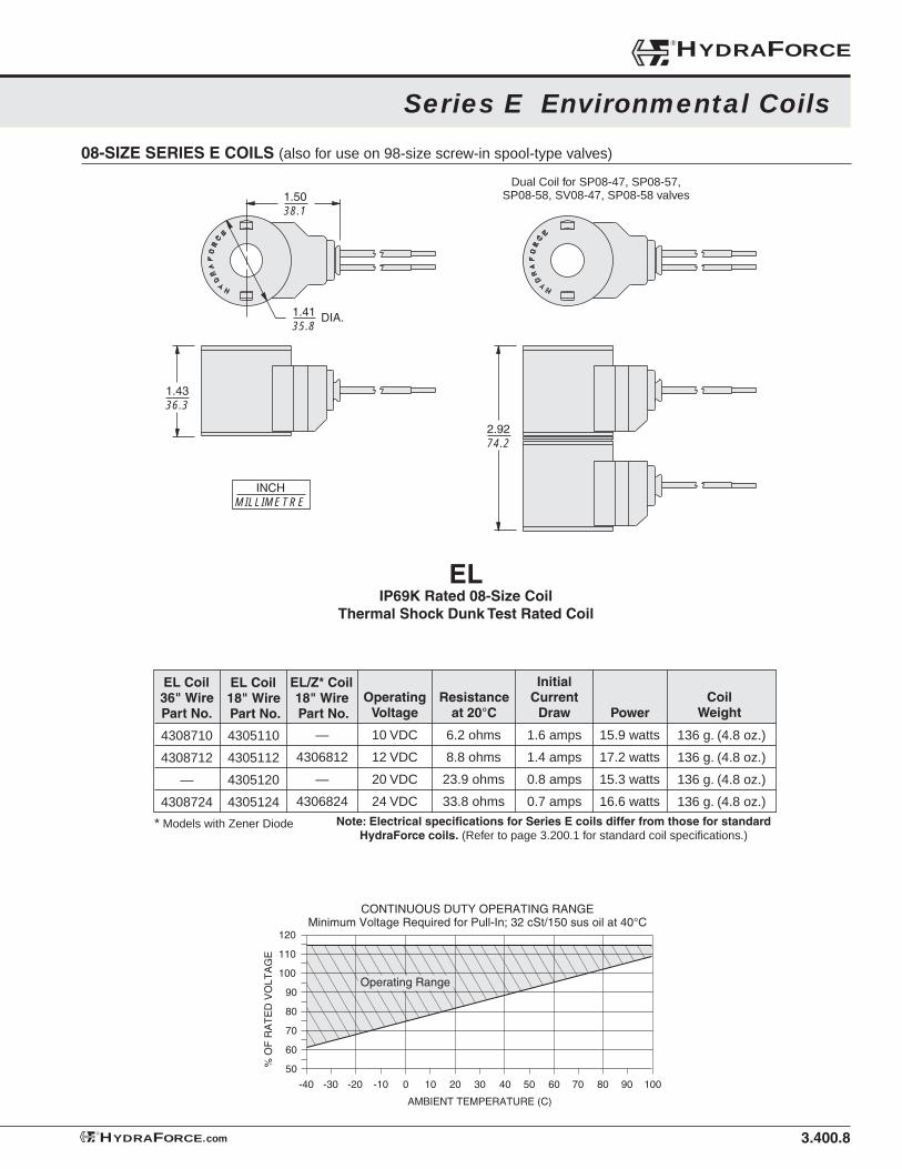
3.400.8
Series E Environmental Coils
08-SIZE SERIES E COILS (also for use on 98-size screw-in spool-type valves)
®HYDRAFORCE
HYDRAFORCE.com®
110
120
60 70 80 90 10050403020100-20 -10-30-40
100
80
90
70
60
50% O
F R
AT
ED
VO
LTA
GE
AMBIENT TEMPERATURE (C)
CONTINUOUS DUTY OPERATING RANGEMinimum Voltage Required for Pull-In; 32 cSt/150 sus oil at 40°C
Operating Range
ELIP69K Rated 08-Size Coil
Thermal Shock Dunk Test Rated Coil
1.4135.8
1.5038.1
1.4336.3
INCHMILLIMETRE
DIA.
2.9274.2
Note: Electrical specifi cations for Series E coils differ from those for standard HydraForce coils. (Refer to page 3.200.1 for standard coil specifi cations.)
CoilWeight
OperatingVoltage
10 VDC
12 VDC
20 VDC
24 VDC
Resistance at 20°C
6.2 ohms
8.8 ohms
23.9 ohms
33.8 ohms
InitialCurrent
Draw
1.6 amps
1.4 amps
0.8 amps
0.7 amps
Power
15.9 watts
17.2 watts
15.3 watts
16.6 watts
EL/Z* Coil18" Wire Part No.
EL Coil18" Wire Part No.
EL Coil36" Wire Part No.
* Models with Zener Diode
—
4306812
—
4306824
4305110
4305112
4305120
4305124
4308710
4308712
—
4308724
136 g. (4.8 oz.)
136 g. (4.8 oz.)
136 g. (4.8 oz.)
136 g. (4.8 oz.)
Dual Coil for SP08-47, SP08-57, SP08-58, SV08-47, SP08-58 valves
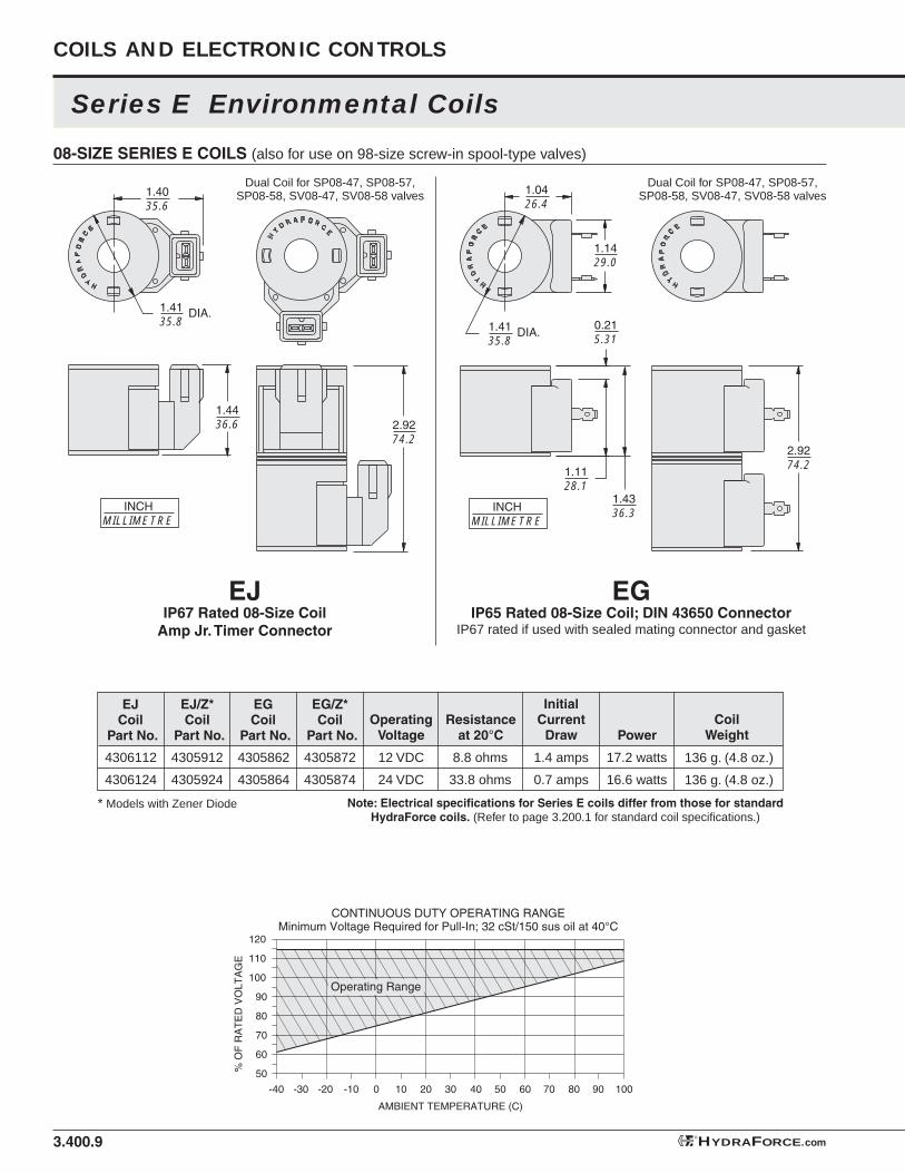
3.400.9
Series E Environmental Coils
COILS AND ELECTRONIC CONTROLS
08-SIZE SERIES E COILS (also for use on 98-size screw-in spool-type valves)
HYDRAFORCE.com®
EGIP65 Rated 08-Size Coil; DIN 43650 Connector
IP67 rated if used with sealed mating connector and gasket
EJIP67 Rated 08-Size Coil
Amp Jr. Timer Connector
Note: Electrical specifi cations for Series E coils differ from those for standard HydraForce coils. (Refer to page 3.200.1 for standard coil specifi cations.)
CoilWeight
OperatingVoltage
12 VDC
24 VDC
Resistance at 20°C
8.8 ohms
33.8 ohms
InitialCurrent
Draw
1.4 amps
0.7 amps
Power
17.2 watts
16.6 watts
EG/Z*Coil
Part No.
EJ/Z*Coil
Part No.
EGCoil
Part No.
EJCoil
Part No.
* Models with Zener Diode
4305872
4305874
4305912
4305924
4305862
4305864
4306112
4306124
136 g. (4.8 oz.)
136 g. (4.8 oz.)
110
120
60 70 80 90 10050403020100-20 -10-30-40
100
80
90
70
60
50% O
F R
AT
ED
VO
LTA
GE
AMBIENT TEMPERATURE (C)
CONTINUOUS DUTY OPERATING RANGEMinimum Voltage Required for Pull-In; 32 cSt/150 sus oil at 40°C
Operating Range
Dual Coil for SP08-47, SP08-57, SP08-58, SV08-47, SV08-58 valves
Dual Coil for SP08-47, SP08-57, SP08-58, SV08-47, SV08-58 valves
1.1128.1
0.215.31
1.4336.3
1.4135.8
1.0426.4
DIA.
2.9274.2
INCHMILLIMETRE
1.1429.0
INCHMILLIMETRE
2.9274.2
1.4135.8
1.4035.6
DIA.
1.4436.6
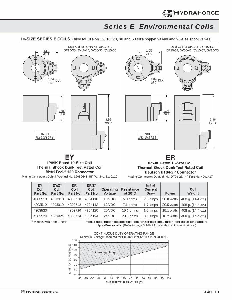
3.400.10
Series E Environmental Coils
®HYDRAFORCE
HYDRAFORCE.com®
10-SIZE SERIES E COILS (Also for use on 12, 16, 20, 38 and 58 size poppet valves and 90-size spool valves)
1.9649.9
3.98101.1
1.8446.7
1.6241.1
DIA.
1.9649.9
3.98101.1
1.8446.7
1.6541.9
DIA.
INCHMILLIMETRE
INCHMILLIMETRE
ERIP69K Rated 10-Size Coil
Thermal Shock Dunk Test Rated CoilDeutsch DT04-2P Connector
Mating Connector: Deutsch No. DT06-2S; HF Part No. 4001417
EYIP69K Rated 10-Size Coil
Thermal Shock Dunk Test Rated CoilMetri-Pack® 150 Connector
Mating Connector: Delphi Packard No. 12052641; HF Part No. 6110119
Please note: Electrical specifi cations for Series E coils differ from those for standard HydraForce coils. (Refer to page 3.200.1 for standard coil specifi cations.)
CoilWeight
OperatingVoltage
10 VDC
12 VDC
20 VDC
24 VDC
Resistance at 20°C
5.0 ohms
7.1 ohms
19.1 ohms
28.5 ohms
InitialCurrent
Draw
2.0 amps
1.7 amps
1.0 amps
0.8 amps
Power
20.0 watts
20.5 watts
19.1 watts
18.2 watts
ER/Z*Coil
Part No.
ERCoil
Part No.
EY/Z*Coil
Part No.
EYCoil
Part No.
* Models with Zener Diode
4303710
4303712
4303720
4303724
4303910
4303912
—
4303924
4303510
4303512
4303520
4303524
4304110
4304112
4304120
4304124
408 g. (14.4 oz.)
408 g. (14.4 oz.)
408 g. (14.4 oz.)
408 g. (14.4 oz.)
110
120
60 70 80 90 10050403020100-20 -10-30-40
100
80
90
70
60
50% O
F R
AT
ED
VO
LTA
GE
AMBIENT TEMPERATURE (C)
Operating Range
CONTINUOUS DUTY OPERATING RANGEMinimum Voltage Required for Pull-In; 32 cSt/150 sus oil at 40°C
Dual Coil for SP10-47, SP10-57, SP10-58, SV10-47, SV10-57, SV10-58
Dual Coil for SP10-47, SP10-57, SP10-58, SV10-47, SV10-57, SV10-58
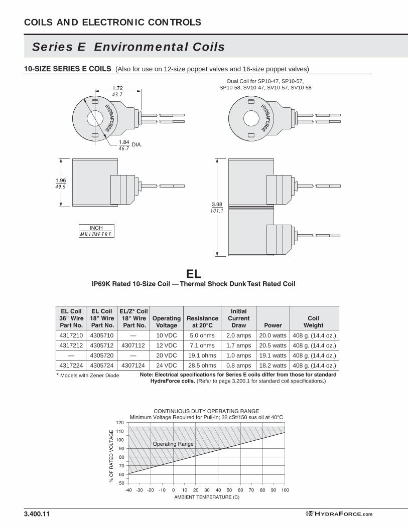
3.400.11
Series E Environmental Coils
COILS AND ELECTRONIC CONTROLS
ELIP69K Rated 10-Size Coil — Thermal Shock Dunk Test Rated Coil
1.9649.9
1.8446.7
1.7243.7
DIA.
INCHMILLIMETRE
3.98101.1
HYDRAFORCE.com®
10-SIZE SERIES E COILS (Also for use on 12-size poppet valves and 16-size poppet valves)
Note: Electrical specifi cations for Series E coils differ from those for standard HydraForce coils. (Refer to page 3.200.1 for standard coil specifi cations.)
CoilWeight
OperatingVoltage
10 VDC
12 VDC
20 VDC
24 VDC
Resistance at 20°C
5.0 ohms
7.1 ohms
19.1 ohms
28.5 ohms
InitialCurrent
Draw
2.0 amps
1.7 amps
1.0 amps
0.8 amps
Power
20.0 watts
20.5 watts
19.1 watts
18.2 watts
* Models with Zener Diode
—
4307112
—
4307124
4305710
4305712
4305720
4305724
4317210
4317212
—
4317224
408 g. (14.4 oz.)
408 g. (14.4 oz.)
408 g. (14.4 oz.)
408 g. (14.4 oz.)
110
120
60 70 80 90 10050403020100-20 -10-30-40
100
80
90
70
60
50% O
F R
AT
ED
VO
LTA
GE
AMBIENT TEMPERATURE (C)
Operating Range
CONTINUOUS DUTY OPERATING RANGEMinimum Voltage Required for Pull-In; 32 cSt/150 sus oil at 40°C
Dual Coil for SP10-47, SP10-57, SP10-58, SV10-47, SV10-57, SV10-58
EL/Z* Coil18" Wire Part No.
EL Coil18" Wire Part No.
EL Coil36" Wire Part No.
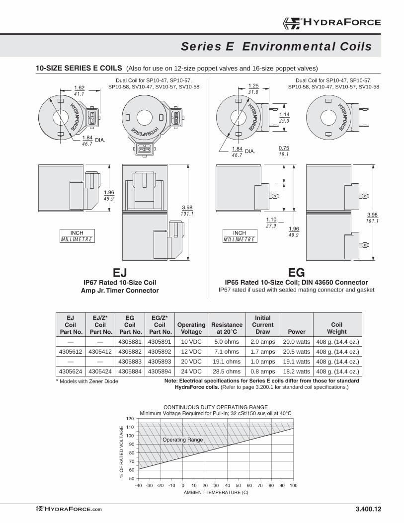
3.400.12
Series E Environmental Coils
10-SIZE SERIES E COILS (Also for use on 12-size poppet valves and 16-size poppet valves)
®HYDRAFORCE
HYDRAFORCE.com®
Note: Electrical specifi cations for Series E coils differ from those for standard HydraForce coils. (Refer to page 3.200.1 for standard coil specifi cations.)
EGIP65 Rated 10-Size Coil; DIN 43650 Connector
IP67 rated if used with sealed mating connector and gasket
CoilWeight
OperatingVoltage
10 VDC
12 VDC
20 VDC
24 VDC
Resistance at 20°C
5.0 ohms
7.1 ohms
19.1 ohms
28.5 ohms
InitialCurrent
Draw
2.0 amps
1.7 amps
1.0 amps
0.8 amps
Power
20.0 watts
20.5 watts
19.1 watts
18.2 watts
EG/Z*Coil
Part No.
EJ/Z*Coil
Part No.
EGCoil
Part No.
EJCoil
Part No.
* Models with Zener Diode
4305891
4305892
4305893
4305894
—
4305412
—
4305424
4305881
4305882
4305883
4305884
—
4305612
—
4305624
408 g. (14.4 oz.)
408 g. (14.4 oz.)
408 g. (14.4 oz.)
408 g. (14.4 oz.)
110
120
60 70 80 90 10050403020100-20 -10-30-40
100
80
90
70
60
50% O
F R
AT
ED
VO
LTA
GE
AMBIENT TEMPERATURE (C)
Operating Range
CONTINUOUS DUTY OPERATING RANGEMinimum Voltage Required for Pull-In; 32 cSt/150 sus oil at 40°C
Dual Coil for SP10-47, SP10-57, SP10-58, SV10-47, SV10-57, SV10-58
Dual Coil for SP10-47, SP10-57, SP10-58, SV10-47, SV10-57, SV10-58
3.98101.1
1.8446.7
1.2531.8
DIA.
INCHMILLIMETRE
1.9649.9
1.1429.0
1.1027.9
0.7519.1
1.9649.9
3.98101.1
1.8446.7
1.6241.1
DIA.
INCHMILLIMETRE
EJIP67 Rated 10-Size Coil
Amp Jr. Timer Connector
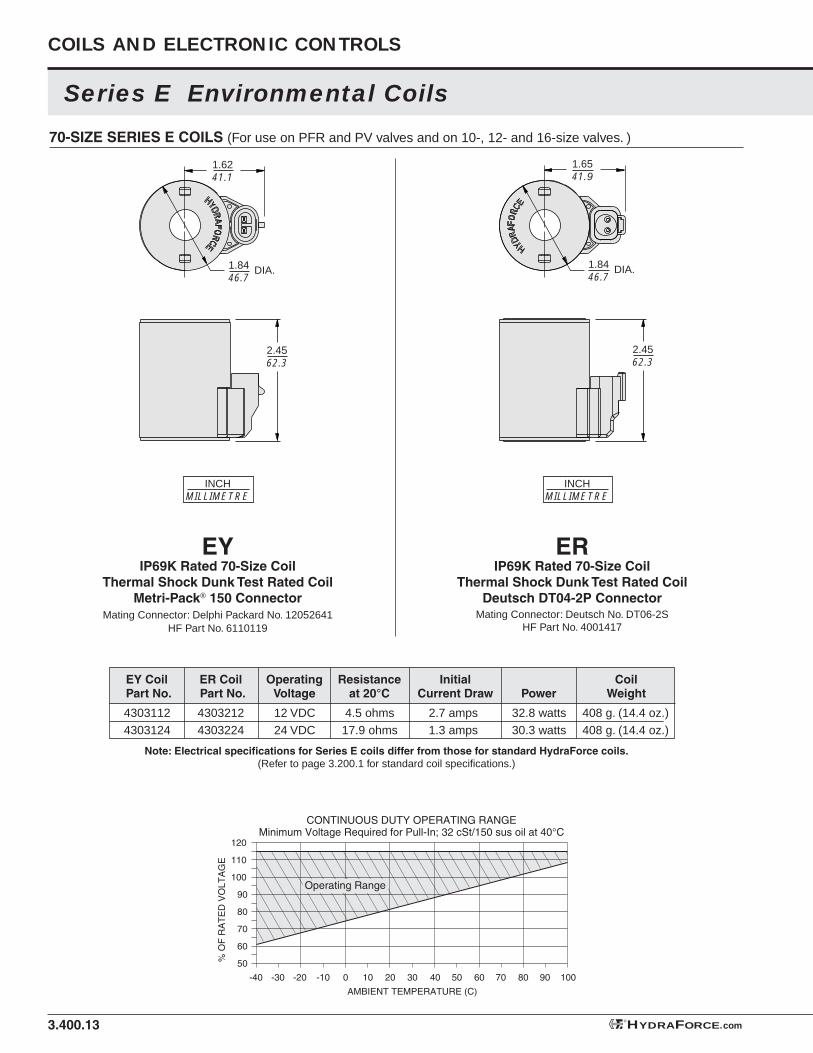
3.400.13
Series E Environmental Coils
COILS AND ELECTRONIC CONTROLS
70-SIZE SERIES E COILS (For use on PFR and PV valves and on 10-, 12- and 16-size valves. )
2.4562.3
1.8446.7
1.6241.1
DIA.
2.4562.3
1.8446.7
1.6541.9
DIA.
INCHMILLIMETRE
INCHMILLIMETRE
ERIP69K Rated 70-Size Coil
Thermal Shock Dunk Test Rated CoilDeutsch DT04-2P Connector
Mating Connector: Deutsch No. DT06-2SHF Part No. 4001417
EYIP69K Rated 70-Size Coil
Thermal Shock Dunk Test Rated CoilMetri-Pack® 150 Connector
Mating Connector: Delphi Packard No. 12052641HF Part No. 6110119
HYDRAFORCE.com®
Note: Electrical specifi cations for Series E coils differ from those for standard HydraForce coils.(Refer to page 3.200.1 for standard coil specifi cations.)
ER Coil Part No.
EY Coil Part No.
OperatingVoltage
Resistance at 20°C
InitialCurrent Draw Power
CoilWeight
43032124303224
43031124303124
12 VDC24 VDC
4.5 ohms17.9 ohms
2.7 amps1.3 amps
32.8 watts30.3 watts
408 g. (14.4 oz.)408 g. (14.4 oz.)
110
120
60 70 80 90 10050403020100-20 -10-30-40
100
80
90
70
60
50% O
F R
AT
ED
VO
LTA
GE
AMBIENT TEMPERATURE (C)
Operating Range
CONTINUOUS DUTY OPERATING RANGEMinimum Voltage Required for Pull-In; 32 cSt/150 sus oil at 40°C
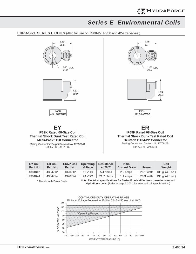
3.400.14
Series E Environmental Coils
EHPR-SIZE SERIES E COILS (Also for use on TS08-27, PV08 and 42-size valves.)
1.5338.9
1.3434.0
1.4637.1
DIA.
INCHMILLIMETRE
Note: Electrical specifi cations for Series E coils differ from those for standard HydraForce coils. (Refer to page 3.200.1 for standard coil specifi cations.)
®HYDRAFORCE
HYDRAFORCE.com®
43047124304724
43207124320724
ER Coil Part No.
EY Coil Part No.
43048124304824
OperatingVoltage
12 VDC24 VDC
Resistance at 20°C
5.4 ohms21.7 ohms
InitialCurrent Draw
2.2 amps1.1 amps
Power
26.1 watts26.3 watts
CoilWeight
136 g. (4.8 oz.)136 g. (4.8 oz.)
110
120
60 70 80 90 10050403020100-20 -10-30-40
100
80
90
70
60
50% O
F R
AT
ED
VO
LTA
GE
AMBIENT TEMPERATURE (C)
CONTINUOUS DUTY OPERATING RANGEMinimum Voltage Required for Pull-In; 32 cSt/150 sus oil at 40°C
Operating Range
ERIP69K Rated 08-Size Coil
Thermal Shock Dunk Test Rated CoilDeutsch DT04-2P Connector
Mating Connector: Deutsch No. DT06-2S
HF Part No. 4001417
EYIP69K Rated 08-Size Coil
Thermal Shock Dunk Test Rated CoilMetri-Pack® 150 Connector
Mating Connector: Delphi Packard No. 12052641HF Part No. 6110119
1.3434.0
1.4035.6
1.5338.9
INCHMILLIMETRE
DIA.
ER/Z* Coil Part No.
* Models with Zener Diode
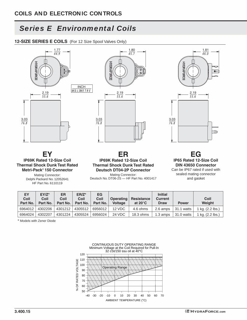
CoilWeight
3.400.15
Series E Environmental Coils
COILS AND ELECTRONIC CONTROLS
EGIP65 Rated 12-Size CoilDIN 43650 Connector
Can be IP67 rated if used with sealed mating connector
and gasket
12-SIZE SERIES E COILS (For 12 Size Spool Valves Only)
1.7744.9
2.1955.6
3.0376.8
3.0376.8
1.8146.0
2.1955.6
3.0376.8
2.1955.6
INCHMILLIMETRE
1.8045.7
110
120
60 7050403020100-20 -10-30-40
100
80
90
70
60
50% O
F R
AT
ED
VO
LTA
GE
AMBIENT TEMPERATURE (°C)
CONTINUOUS DUTY OPERATING RANGEMinimum Voltage at the Coil Required for Pull-In
32 cSt/150 ssu oil at 40°C
Operating Range
EYIP69K Rated 12-Size Coil
Thermal Shock Dunk Test Rated Metri-Pack® 150 Connector
Mating Connector: Delphi Packard No. 12052641
HF Part No. 6110119
EGCoil
Part No.Operating
VoltageResistance
at 20°C
InitialCurrent
Draw Power
ER/Z*Coil
Part No.
HYDRAFORCE.com®
ERCoil
Part No.
EY/Z*Coil
Part No.
EYCoil
Part No.
* Models with Zener Diode
ERIP69K Rated 12-Size Coil
Thermal Shock Dunk Test RatedDeutsch DT04-2P Connector
Mating Connector: Deutsch No. DT06-2S — HF Part No. 4001417
6964012
6964024
4302206
4302207
4301212
4301224
4305512
4305524
6956012
6956024
12 VDC
24 VDC
4.6 ohms
18.3 ohms
2.6 amps
1.3 amps
31.1 watts
31.0 watts
1 kg. (2.2 lbs.)
1 kg. (2.2 lbs.)

3.400.16
EWIP65 Rated 12-Size CoilDual 18 Gauge Leads
with Weather-Pack® ConnectorMating Connector: Delphi Packard No. 12015792
12-SIZE SERIES E COILS (For 12 Size Spool Valves Only)
2.1955.6
3.0376.8
2.1955.6
3.0376.8
2.1955.6
3.0376.8
1.7945.6
1.6642.2
7.84199.1
1.6642.2
16.34415
Approx.Lead Length:
INCHMILLIMETRE
ESIP65 Rated 12-Size Coil
Dual Spades SAE J858a
ELIP65 Rated 12-Size CoilDual Leads – 18 Gauge
110
120
60 7050403020100-20 -10-30-40
100
80
90
70
60
50% O
F R
AT
ED
VO
LTA
GE
AMBIENT TEMPERATURE (°C)
CONTINUOUS DUTY OPERATING RANGEMinimum Voltage at the Coil Required for Pull-In
32 cSt/150 ssu oil at 40°C
Operating Range
OperatingVoltage
10 VDC
12 VDC
24 VDC
Resistance at 20°C
3.2 ohms
4.6 ohms
18.3 ohms
InitialCurrent Draw
3.1 amps
2.6 amps
1.3 amps
Power
31.2 watts
31.1 watts
31.0 watts
CoilWeight
1 kg. (2.2 lbs.)
1 kg. (2.2 lbs.)
1 kg. (2.2 lbs.)
—
6853012
6853024
EW Coil Part No.
6852010
6852012
6852024
EL Coil Part No.
—
6851012
6851024
ES Coil Part No.
Series E Environmental Coils
®HYDRAFORCE
HYDRAFORCE.com®
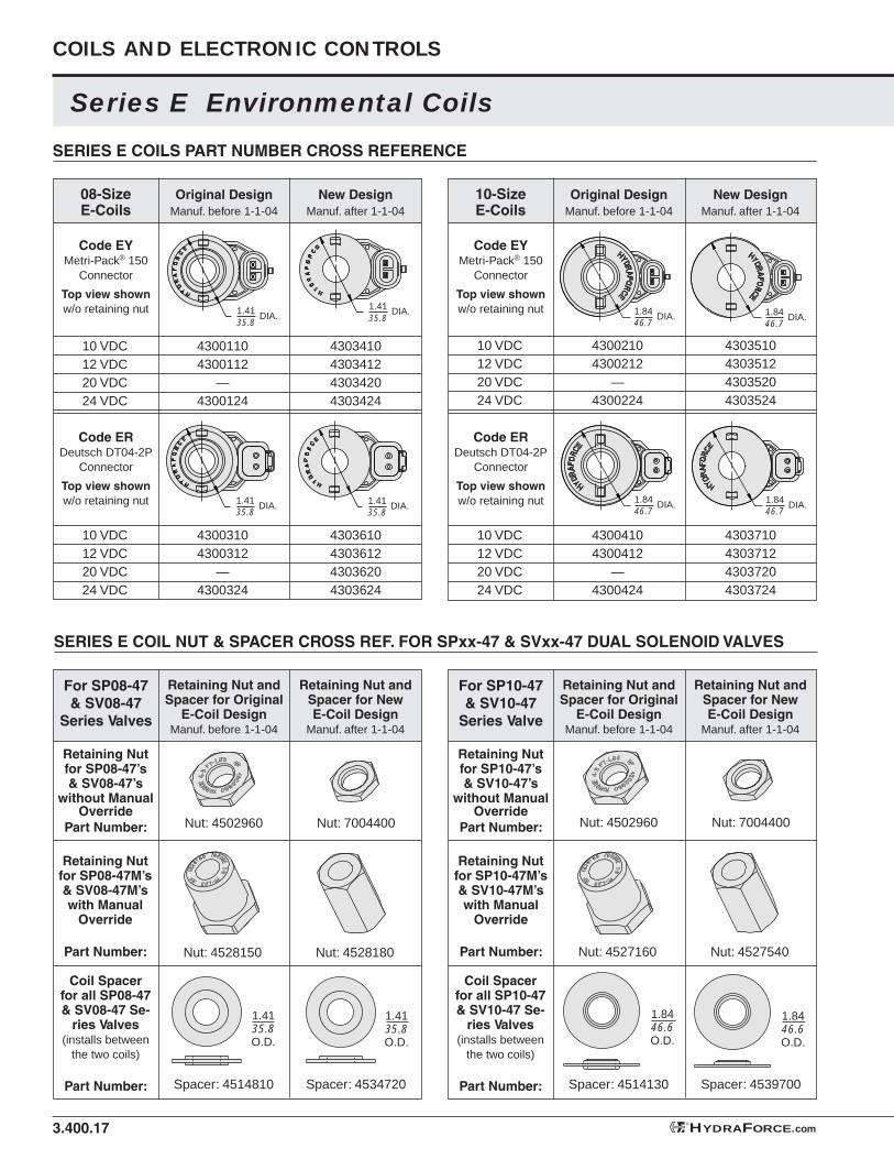
Series E Environmental Coils
COILS AND ELECTRONIC CONTROLS
3.400.17
SERIES E COILS PART NUMBER CROSS REFERENCE
Original DesignManuf. before 1-1-04
New DesignManuf. after 1-1-04
08-SizeE-Coils
Code EYMetri-Pack® 150
Connector
Top view shown w/o retaining nut
10 VDC12 VDC20 VDC24 VDC
43001104300112
—4300124
4303410430341243034204303424
Code ERDeutsch DT04-2P
Connector
Top view shown w/o retaining nut
10 VDC12 VDC20 VDC24 VDC
43003104300312
—4300324
4303610430361243036204303624
Original DesignManuf. before 1-1-04
New DesignManuf. after 1-1-04
10-SizeE-Coils
Code EYMetri-Pack® 150
Connector
Top view shown w/o retaining nut
10 VDC12 VDC20 VDC24 VDC
43002104300212
—4300224
4303510430351243035204303524
Code ERDeutsch DT04-2P
Connector
Top view shown w/o retaining nut
10 VDC12 VDC20 VDC24 VDC
43004104300412
—4300424
4303710430371243037204303724
1.4135.8
DIA.1.4135.8
DIA.
1.4135.8
DIA. 1.4135.8
DIA.
1.8446.7
DIA. 1.8446.7
DIA.
1.8446.7
DIA. 1.8446.7
DIA.
SERIES E COIL NUT & SPACER CROSS REF. FOR SPxx-47 & SVxx-47 DUAL SOLENOID VALVES
Retaining Nut and Spacer for Original
E-Coil DesignManuf. before 1-1-04
Retaining Nut and Spacer for New E-Coil Design
Manuf. after 1-1-04
Nut: 4502960 Nut: 7004400
Nut: 4528150 Nut: 4528180
Spacer: 4514810 Spacer: 4534720
Coil Spacerfor all SP08-47& SV08-47 Se-
ries Valves(installs between
the two coils)
Part Number:
Retaining Nut and Spacer for Original
E-Coil DesignManuf. before 1-1-04
Retaining Nut and Spacer for New E-Coil Design
Manuf. after 1-1-04
For SP10-47 & SV10-47
Series Valve
Retaining Nutfor SP10-47’s & SV10-47’s
without Manual Override
Part Number: Nut: 4502960 Nut: 7004400
Nut: 4527160 Nut: 4527540
Spacer: 4514130 Spacer: 4539700
Retaining Nutfor SP10-47M’s & SV10-47M’s with Manual
Override
Part Number:
Coil Spacerfor all SP10-47 & SV10-47 Se-
ries Valves(installs between
the two coils)
Part Number:
1.4135.8O.D.
1.4135.8O.D.
1.8446.6O.D.
1.8446.6O.D.
For SP08-47 & SV08-47
Series Valves
Retaining Nutfor SP08-47’s & SV08-47’s
without Manual Override
Part Number:
Retaining Nutfor SP08-47M’s & SV08-47M’s with Manual
Override
Part Number:
HYDRAFORCE.com®
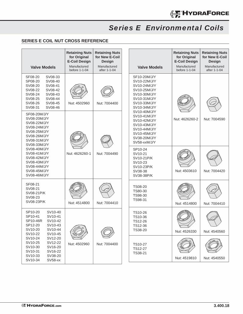
3.400.18
Series E Environmental Coils
SERIES E COIL NUT CROSS REFERENCE
Retaining Nuts for Original
E-Coil Design
Valve Models
SF08-20SP08-20SV08-20SV08-22SV08-24SV08-25SV08-26SV08-31
Nut: 4502960 Nut: 7004400
Nut: 4626260-1 Nut: 7004490
Retaining Nuts for New E-Coil
Design
SV08-33SV08-40SV08-41SV08-42SV08-43SV08-44SV08-45SV08-46
SF08-20M/J/YSV08-20M/J/YSV08-22M/J/YSV08-24M/J/YSV08-25M/J/YSV08-26M/J/YSV08-31M/J/YSV08-33M/J/YSV08-40M/J/YSV08-41M/J/YSV08-42M/J/YSV08-43M/J/YSV08-44M/J/YSV08-45M/J/YSV08-46M/J/Y
SF08-21SV08-21SV08-21P/KSV08-23SV08-23P/K Nut: 4514800 Nut: 7004410
SP10-20SP10-41SP10-46RSP12-20SV10-20SV10-22SV10-24SV10-25SV10-30SV10-31SV10-33SV10-34
SV10-40SV10-41SV10-42SV10-43SV10-44SV10-45SV12-20SV12-22SV16-20SV16-22SV38-20SV58-xx
Nut: 4502960 Nut: 7004400
SF10-20M/J/YSV10-22M/J/YSV10-24M/J/YSV10-25M/J/YSV10-30M/J/YSV10-31M/J/YSV10-33M/J/YSV10-34M/J/YSV10-40M/J/YSV10-41M/J/YSV10-42M/J/YSV10-43M/J/YSV10-44M/J/YSV10-45M/J/YSV38-20M/J/YSV58-xxM/J/Y
SP10-24SV10-21SV10-21P/KSV10-23SV10-23P/KSV38-38SV38-38P/K
Manufactured before 1-1-04
Manufactured after 1-1-04
Retaining Nuts for Original
E-Coil Design
Valve Models
Nut: 4626260-2 Nut: 7004590
Nut: 4503610 Nut: 7004420
Retaining Nuts for New E-Coil
Design
Nut: 4514800 Nut: 7004410
Nut: 4526330 Nut: 4540560
Manufactured before 1-1-04
Manufactured after 1-1-04
TS08-20TS80-30TS98-30TS98-31
TS10-27TS12-27TS38-21
TS10-26TS10-36TS12-26TS12-36TS38-20
Nut: 4519810 Nut: 4540550
®HYDRAFORCE
HYDRAFORCE.com®
Top Related