


Talen
Pages
Wettelijk


Faculteit WetenschappenVakgroep Computerwetenschappen
Design Structure Matricesfor Software Development
Proefschrift ingediend met het oog op het behalen van de graad van Licentiaat in de Informatica
Matthias Stevens
Promotor: Prof. Dr. Theo D’HondtBegeleiders: Dr. Johan Brichau
Dr. Andy Kellens
20 augustus 2007

Faculty of ScienceDepartment of Computer Science
Design Structure Matricesfor Software Development
Graduation thesis submitted with intention to obtain the degree of Licenciate in Computer Science
Matthias Stevens
Promotor: Prof. Dr. Theo D’HondtAdvisors: Dr. Johan Brichau
Dr. Andy Kellens
August 20, 2007

Nederlandstalige Samenvatting
In deze dissertatie presenteren we ons onderzoek naar toepassingen van Design StructureMatrices (DSMs) en gerelateerde technieken in de context van software ontwikkeling. Wespitsen ons toe op twee invalshoeken.
Enerzijds onderzoeken we of de combinatie van DSMs en het Net Option Value (NOV)model kan gebruikt worden als een kwantitatieve methodologie voor het onderzoeken vanmodulariteit in software ontwerpen. Om deze methodologie te evalueren introduceren weeen software programma om ze te ondersteunen en passen we ze toe om een vergelijkendonderzoek te doen op aspect-georienteerde en object-georienteerde implementaties van de-sign patronen. Op basis van deze experimenten formuleren we kritieken met betrekking totde toepasbaarheid van het NOV model als een modulariteitsmetriek voor software.
Anderzijds onderzoeken we of DSM diagrammen kunnen dienen als een basis voor eennieuw soort software applicatie ter ondersteuning van software ontwikkelaars. We for-muleren vereisten en een concrete aanpak voor een DSM-gebaseerde source-code browservoor object-georienteerde software ontwikkeling. Om deze aanpak te valideren presenterenwe een prototype van een dergelijke applicatie en demonstreren we hoe deze kan gebruiktworden in realistische situaties.
iv

Abstract
In this dissertation we present our research into applications of Design Structure Matrices(DSMs) and related techniques in the context of software development. We pursue tworesearch angles.
On the one hand, we investigate whether the combination of DSMs and the Net OptionValue (NOV) model can be used as a quantitative methodology to assess modularity insoftware design. In order to evaluate this methodology we introduce a tool to facilitate itsuse and we apply it to conduct a comparative assessment on aspect-oriented and object-oriented design pattern implementations. Based on these experiments we formulate critiqueswith regard to the applicability of the NOV model as a modularity metric for software.
On the other hand, we investigate whether DSM diagrams can serve as a basis for a novelkind of support tool for software developers. We formulate requirements and a concreteapproach for a DSM-based source-code browser for object-oriented software development.In order to validate this approach we present a prototype implementation of such a tool andwe demonstrate how it can be used in real-world situations.
v

Acknowledgements
I would never have completed this dissertation without the support I received from a numberof people. Therefore I would like to express my gratitude towards:
Prof. Dr. Theo D’Hondt, for promoting this thesis.
My advisors Dr. Andy Kellens and Dr. Johan Brichau, for coming up with the initial ideasfor and contributions to the research that is covered by this dissertation. I would also liketo thank them for proofreading and commenting on the text and for the dedication andpatience they showed while I was writing it, as well as during my apprenticeship at the lab.
My girlfriend Sarah, for her invaluable support, her patience and her love. I will do every-thing in my power to make up for many long weeks she had to miss me while I was slavingaway at this dissertation.
My parents, for their unconditional support and encouragement and for giving me the pos-sibility to obtain a second higher education degree. I would also like to thank my motherfor supplying me with provisions and my farther for his last-minute proofreading.
My brother Jasper, for his support and for the fun phone calls during his and my absence.
Andreas, Axel, Erwin, Jonas, Julie, Matthias, Pieter, Rien and my other friends in Ghent,for distracting me and for constantly enquiring when I would join them to go out again.
Karlien, for her companionship and support during our daily long working sessions at thelab in the course of the best part of July and August.
Clement, Dries, Erik, Isabel, Karlien, Lode, Pierre, Pieter, Thomas and my other fellowstudents and members of Infogroep, for making the past three years at the university sucha fun time.
Everyone at the Programming Technology Lab, for providing a pleasant and serene workingenvironment.
The Vrije Universiteit Brussel and its Departement of Computer Science, for providing anexcellent education.
And last but not least, my cat Puck, for always cheering me up.
And of course, Ever Marcassou for his support and companionship.
vi

Contents
1 Introduction 11.1 Context . . . . . . . . . . . . . . . . . . . . . . . . . . . . . . . . . . . . 11.2 DSMs for Software Development . . . . . . . . . . . . . . . . . . . . . . 2
1.2.1 Evaluating Modularity with DSMs and NOV . . . . . . . . . . . . 21.2.2 DSM-based Support Tools . . . . . . . . . . . . . . . . . . . . . . 3
1.3 Approach . . . . . . . . . . . . . . . . . . . . . . . . . . . . . . . . . . . 31.4 Outline of the Dissertation . . . . . . . . . . . . . . . . . . . . . . . . . . 31.5 Notable Contributions . . . . . . . . . . . . . . . . . . . . . . . . . . . . 4
2 Design Structure Matrices 62.1 Introduction . . . . . . . . . . . . . . . . . . . . . . . . . . . . . . . . . 62.2 Basic Concepts . . . . . . . . . . . . . . . . . . . . . . . . . . . . . . . . 7
2.2.1 A Matrix of Parameters . . . . . . . . . . . . . . . . . . . . . . . 72.2.2 Dependencies . . . . . . . . . . . . . . . . . . . . . . . . . . . . 7
2.3 Baldwin & Clark: DSMs & Modularity . . . . . . . . . . . . . . . . . . . 92.3.1 What is Modularity? . . . . . . . . . . . . . . . . . . . . . . . . . 102.3.2 Representing Modularity in Designs using DSMs . . . . . . . . . . 102.3.3 Design Rules . . . . . . . . . . . . . . . . . . . . . . . . . . . . . 112.3.4 Modularity in Design . . . . . . . . . . . . . . . . . . . . . . . . . 122.3.5 Modular Operators . . . . . . . . . . . . . . . . . . . . . . . . . . 132.3.6 Net Option Value of a Modular Design . . . . . . . . . . . . . . . 13
2.3.6.1 Real Options . . . . . . . . . . . . . . . . . . . . . . . . 132.3.6.2 NOV Formulae . . . . . . . . . . . . . . . . . . . . . . . 142.3.6.3 NOV Calculation Example . . . . . . . . . . . . . . . . . 162.3.6.4 Strength and Weakness . . . . . . . . . . . . . . . . . . 18
2.4 Overview of Applications . . . . . . . . . . . . . . . . . . . . . . . . . . . 192.4.1 Roles of DSMs . . . . . . . . . . . . . . . . . . . . . . . . . . . . 19
2.4.1.1 Project Management Tool . . . . . . . . . . . . . . . . . 192.4.1.2 System Analysis Tool . . . . . . . . . . . . . . . . . . . 20
2.4.2 Types of DSMs . . . . . . . . . . . . . . . . . . . . . . . . . . . 202.5 Conclusions . . . . . . . . . . . . . . . . . . . . . . . . . . . . . . . . . . 22
vii
3 DSM+NOV Tool 233.1 Introduction . . . . . . . . . . . . . . . . . . . . . . . . . . . . . . . . . 233.2 Requirements . . . . . . . . . . . . . . . . . . . . . . . . . . . . . . . . . 243.3 Approach . . . . . . . . . . . . . . . . . . . . . . . . . . . . . . . . . . . 243.4 DSM+NOV Tool . . . . . . . . . . . . . . . . . . . . . . . . . . . . . . . 24
3.4.1 Net Option Value Calculation . . . . . . . . . . . . . . . . . . . . 273.4.2 Module- and Parameter-level DSMs . . . . . . . . . . . . . . . . . 28
3.5 Conclusions . . . . . . . . . . . . . . . . . . . . . . . . . . . . . . . . . . 32
4 Assessing Aspect-Orientation using DSMs and NOV 334.1 Introduction . . . . . . . . . . . . . . . . . . . . . . . . . . . . . . . . . 334.2 Aspect-Oriented Software Development . . . . . . . . . . . . . . . . . . . 34
4.2.1 Modularisation and Separation of Concerns . . . . . . . . . . . . . 354.2.2 Crosscutting Concerns . . . . . . . . . . . . . . . . . . . . . . . . 354.2.3 Aspectual Decomposition & Aspects . . . . . . . . . . . . . . . . 374.2.4 AspectJ . . . . . . . . . . . . . . . . . . . . . . . . . . . . . . . 394.2.5 The Fragile Pointcut Problem . . . . . . . . . . . . . . . . . . . . 41
4.3 Related Work . . . . . . . . . . . . . . . . . . . . . . . . . . . . . . . . 424.4 Design Patterns . . . . . . . . . . . . . . . . . . . . . . . . . . . . . . . 43
4.4.1 Aspect-Oriented Design Patterns . . . . . . . . . . . . . . . . . . 444.5 Experiments . . . . . . . . . . . . . . . . . . . . . . . . . . . . . . . . . 44
4.5.1 Approach . . . . . . . . . . . . . . . . . . . . . . . . . . . . . . . 454.5.2 Observer Pattern . . . . . . . . . . . . . . . . . . . . . . . . . . . 464.5.3 Provisional Conclusions . . . . . . . . . . . . . . . . . . . . . . . 504.5.4 Builder Pattern . . . . . . . . . . . . . . . . . . . . . . . . . . . . 514.5.5 Composite Pattern . . . . . . . . . . . . . . . . . . . . . . . . . . 524.5.6 Conclusions . . . . . . . . . . . . . . . . . . . . . . . . . . . . . 53
4.5.6.1 Summary . . . . . . . . . . . . . . . . . . . . . . . . . 534.5.6.2 Evaluating the Applicability of the NOV Model . . . . . . 53
4.6 Conclusions . . . . . . . . . . . . . . . . . . . . . . . . . . . . . . . . . . 55
5 DSM-based Code Browsers 565.1 Introduction . . . . . . . . . . . . . . . . . . . . . . . . . . . . . . . . . 565.2 Motivation . . . . . . . . . . . . . . . . . . . . . . . . . . . . . . . . . . 57
5.2.1 Modularity and Dependencies in Object-Oriented Software . . . . . 575.2.2 Dependency Management . . . . . . . . . . . . . . . . . . . . . . 58
5.3 Rationale . . . . . . . . . . . . . . . . . . . . . . . . . . . . . . . . . . . 605.3.1 Requirements . . . . . . . . . . . . . . . . . . . . . . . . . . . . 605.3.2 Approach . . . . . . . . . . . . . . . . . . . . . . . . . . . . . . . 61
5.3.2.1 DSM-based Visualisation . . . . . . . . . . . . . . . . . 615.3.2.2 Source Code Browser . . . . . . . . . . . . . . . . . . . 685.3.2.3 Metaprogramming-based Analysis . . . . . . . . . . . . . 68
viii
5.3.2.4 Summary . . . . . . . . . . . . . . . . . . . . . . . . . 705.4 DSMBrowser . . . . . . . . . . . . . . . . . . . . . . . . . . . . . . . . . 70
5.4.1 Context . . . . . . . . . . . . . . . . . . . . . . . . . . . . . . . 705.4.2 User Interface . . . . . . . . . . . . . . . . . . . . . . . . . . . . 715.4.3 DSM Model . . . . . . . . . . . . . . . . . . . . . . . . . . . . . 725.4.4 Smalltalk Language Support . . . . . . . . . . . . . . . . . . . . . 745.4.5 Analysis Features . . . . . . . . . . . . . . . . . . . . . . . . . . 74
5.5 Related Work . . . . . . . . . . . . . . . . . . . . . . . . . . . . . . . . 755.5.1 Lattix LDM . . . . . . . . . . . . . . . . . . . . . . . . . . . . . 765.5.2 NDepend . . . . . . . . . . . . . . . . . . . . . . . . . . . . . . . 775.5.3 DeMatrix . . . . . . . . . . . . . . . . . . . . . . . . . . . . . . . 78
5.6 Conclusions . . . . . . . . . . . . . . . . . . . . . . . . . . . . . . . . . . 79
6 DSMBrowser Case Studies 806.1 Introduction . . . . . . . . . . . . . . . . . . . . . . . . . . . . . . . . . 806.2 Source Code Exploration . . . . . . . . . . . . . . . . . . . . . . . . . . . 816.3 Dependency Management . . . . . . . . . . . . . . . . . . . . . . . . . . 84
6.3.1 Tracking Framework Dependencies . . . . . . . . . . . . . . . . . 846.3.2 Finding and Evaluating Modularisation Opportunities . . . . . . . . 86
6.3.2.1 Minimising Dependencies with Indirections . . . . . . . . 886.3.2.1.1 Message Send Dependencies . . . . . . . . . . 886.3.2.1.2 Inheritance Dependencies . . . . . . . . . . . . 93
6.3.2.2 Eliminating Dependencies with Code Duplication . . . . . 956.3.2.2.1 Message Send Dependencies . . . . . . . . . . 966.3.2.2.2 Inheritance Dependencies . . . . . . . . . . . . 96
6.4 Conclusions . . . . . . . . . . . . . . . . . . . . . . . . . . . . . . . . . . 97
7 Conclusions 997.1 Summary . . . . . . . . . . . . . . . . . . . . . . . . . . . . . . . . . . . 997.2 Contributions . . . . . . . . . . . . . . . . . . . . . . . . . . . . . . . . . 1007.3 Future Work . . . . . . . . . . . . . . . . . . . . . . . . . . . . . . . . . 100
7.3.1 Evaluating Modularity with DSMs . . . . . . . . . . . . . . . . . . 1017.3.2 DSM-based Support Tools . . . . . . . . . . . . . . . . . . . . . . 101
7.4 Conclusion . . . . . . . . . . . . . . . . . . . . . . . . . . . . . . . . . . 102
A The Q(k) distribution 103
Bibliography 105
ix
Chapter 1
Introduction
1.1 Context
In aiming for reduced complexity, higher quality, better reusability and lower development andmaintenance costs, software development has evolved through a number of paradigms. Sincethe days of machine-level assembly languages, the procedural, functional and object-orientedparadigms – among others – have been introduced. Each of these paradigms brought newabstraction mechanisms, programming language features and design techniques.
The power of an abstraction mechanism is that it provides a means of modularisation, whichallows software to be constructed from separate, cooperating modules. Modularity is per-haps the most important property developers strive for during the design and implementationof computer programs. The reason is that – in line with grand principles such as informa-tion hiding [55], the separation of concerns [18], encapsulation, isolation, etc. – modularityreduces overall complexity and increases reusability, evolability and maintainability.
Although the evolution of programming languages and design techniques has increased ourability to design software with higher modularity, there is still ample room for improve-ments. For instance, the vast size and complexity of many software development projectscan quickly cause developers to lose track of the situation. Moreover, there are facets ofcomputer programs that cannot be modularised using existing paradigms. Consequently, re-search into new paradigms continues to flourish. Recently the aspect-orientation paradigm,which claims improved modularisation properties over older paradigms by providing modu-larisation mechanisms for crosscutting concerns [36], has seen a great deal of attention.
While it is widely accepted that it is beneficial to design software systems in a modularfashion, it is not trivial to quantify the degree of modularity and other perceived qualities ofsoftware designs. By extension, claims with regard to the modularisation properties of newsoftware development paradigms are difficult to validate. Therefore it generally takes a sub-stantial amount of time for the advantages of new paradigms to become widely recognised.
1

However software developers need more than advanced languages and design techniques.They also rely heavily on a diverse set of support tools to make their lives easier. Exam-ples include intelligent integrated development environments (IDEs), source-code browsers,documentation systems, versioning and collaboration systems, case tools, refactoring tools,testing frameworks, etc. Various kinds of diagrams, models and visualizations also play animportant supporting role in every phase of the software development cycle and allow tobridge and integrate those phases.
The importance of support tools should not be underestimated and we believe that softwaredevelopment as a discipline can benefit just as much from innovations in this context as itcan from research into new paradigms.
1.2 DSMs for Software Development
In this dissertation we investigate how Design Structure Matrices (DSMs) and related tech-niques can be applied to support software development in a broad sense. DSM diagramswere conceived [67, 68] to help manage the complexity of technical systems. They providean abstract visualisation of the constituent parts of a system and the dependencies amongthose parts.
We believe that DSMs offer interesting opportunities for innovations in software develop-ment. We see possible applications on two fronts. On the one hand, we believe that DSMsoffer an innovative way to evaluate modularity in software design. On the other hand, webelieve that DSM diagrams can serve as a basis for a novel kind of support tool for softwaredevelopment. On both fronts, it is the focus on the modular structure of systems and theexplicit depiction of – the distribution and nature of – dependencies, which make DSMsinteresting in the context of software development.
1.2.1 Evaluating Modularity with DSMs and NOV
The structural elements of software need to cooperate to perform the functionality usersexpect. Such cooperation unavoidably introduces dependencies among those elements.Striving for modularity in software design means that structural elements are arranged inunits called modules, where the goal is to maximise the dependency – or coupling – ofelements within a module and to minimise the dependency to elements in other modules.Clearly there are degrees of dependency, thus there are degrees of modularity. Differentdesigns for a software system can achieve different degrees of modularity. So if modularityis to be maximised, not all designs are equally good.
We believe that DSMs can offer the necessary insight to study and reason about the phenom-ena of modularity and dependency in software design. Moreover, the combination of DSMs
2

with a related technique called Net Option Value (NOV) [5], could constitute a powerfulmetric to quantitatively evaluate the degree of modularity achieved by software designs.
1.2.2 DSM-based Support Tools
The issue of modularity and dependency should not be forgotten once the design for asoftware system has been decided upon. Software developers should always be aware ofthe prevailing dependencies in implementations and they should try improve modularity byminimising dependencies throughout the lifecycle of the product.
We believe that DSM-based support tools for software development offer new opportunitiesbecause DSMs communicate information on prevailing dependencies in a clear and conciseway. Furthermore, we expect that DSM visualisations can facilitate the identification ofopportunities for dependency minimisations.
1.3 Approach
In our work we approach the application of DSMs in software development from the twoangles introduced above.
The first part of our research covers an evaluation of the combination of DSMs and NOVas a methodology for quantitative assessment and comparison of modularity in softwaredesigns. Inspired by the work of Lopes & Bajracharya [44, 45], we take the opportunityto link this exploration to the popular Aspect-Oriented Software Development (AOSD)research field. To evaluate the combination of DSMs and NOV, we apply this methodologyto assess the claimed modularity advantages of the aspect-orientation paradigm over theobject-orientation paradigm. We use aspect-oriented and object-oriented implementations[24] of the GoF design patterns [22] as the subject for this case study.
The second part of our research explores the use of DSM diagrams as a basis for supporttools for Object-Oriented Software Development (OOSD). Starting out from observationsconcerning the discipline of OOSD, we develop a rationale for a DSM-based, IDE-integratedsource code browser with metaprogramming facilities, to effectively support developers incommon tasks related to dependency management. We provide a prototype implementationof such a tool to perform experiments and to validate our claims in real-world scenarios.
1.4 Outline of the Dissertation
This document is structured in accordance with the dual approach we follow in our work.Each research angle is covered by two chapters, which are preceded by an essential intro-ductory chapter on DSMs.
3
Chapter 2 presents an in-depth introduction into DSMs, their origins and applications andrelated techniques such as NOV.
The next two chapters cover our research into to application of DSMs and NOV as amethodology for quantitative assessment of modularity in software designs. In Chapter 3 weintroduce a novel software tool which is intended to facilitate experimentation with DSMsand the NOV model. In Chapter 4 we present an evaluation of the merits of the NOVmodel as a modularity metric for software, based on experiments on aspect-oriented andobject-oriented design pattern implementations.
The following two chapters are about our research into the application of DSM diagramsas a basis for support tools for OOSD. In Chapter 5 we investigate the possibilities andrequirements for such innovative tools and we introduce a prototype implementation. InChapter 6 we present case studies which demonstrate how the prototype, or future similartools, can assist software developers in common tasks.
We conclude this dissertation in Chapter 7, which provides a summary of our work andcontributions, followed by an overview of future research directions and our final concludingremarks.
1.5 Notable Contributions
In this dissertation we present the following original contributions:
• A comprehensive introduction to DSMs and related techniques such as NOV, whichprepares readers for passive and active use of DSM diagrams for both academic andprofessional purposes;
• A novel software tool which facilitates the application of the DSM+NOV methodologyfor design assessments, as well as exploration of the methodology itself. The toolintroduces an innovative technique to assess system designs by focussing on twohierarchical levels;
• An evaluation of the DSM+NOV methodology as a technique for qualitative assess-ment of software. This work introduces novel ideas for analysis of software using theNOV model, but also leads to important questions regarding the applicability of themodel as a modularity metric for software design;
• A rationale for a novel DSM-based support tool for OOSD and a prototype imple-mentation of such a tool. This work introduces a unique approach which combinestree-based DSM visualisations and metaprogramming-based analysis facilities in anextendable, IDE-integrated source-code browser.
4

• Case studies which demonstrate how DSM-based source browsers can assist softwaredevelopers in real-world tasks, most importantly in finding and evaluating modulari-sation opportunities by means of ad-hoc metaprograms.
5

Chapter 2
Design Structure Matrices
In this chapter we present a thorough introduction to Design Structure Matrixes (DSMs),which is essential in view of the following chapters. The main topics we cover are the originsand basic characteristics of DSMs and an in-depth discussion of the theory of Baldwin &Clark – which combines DSMs with a mathematical model, called Net Option Value (NOV),to quantitatively assess the economic value of designs.
2.1 Introduction
Due to the technological advances that dominate our society and economy, the complexityof the products, processes, organizations, and markets that surround us is ever-growing.Complexity is a major obstacle to design and develop successful products and services, butcomplex systems also facilitate better functionality and enable otherwise impossible innova-tions. Consequently, good complexity management can be a vital competitive advantage toany organization [91].
The Design Structure Matrix (DSM)1 is a complexity management technique that has provedto be valuable for managing, designing, modelling, analysing and optimising technical sys-tems, complex organisations, sizeable engineering projects, densely networked processes andlarge market structures [91].
A DSM is a diagram that visualises a system or a project using a compact matrix repre-sentation. The matrix confronts the constituent parts (parameters, subsystems, activities,tasks, ...) and indicates the dependencies among those. Depending on the context, thedependency patterns can represent different aspects of the system or project.
DSMs where first conceived by Donald Steward at General Electric in the late 1960s [67],
1 Design Structure Matrices are also known as Dependency Structure Matrices, Problem Solving Matricesand Design Precedence Matrices.
6

but it took until 1981 before his work was published [68]. In his work Steward proposeda novel method, called the Design Structure System, to manage the complexity of largesystems or engineering projects using DSMs.
Despite being conceived as a project management tool, a DSM is an analysis and designinstrument that lends itself to a multitude of other applications across a wide range of do-mains and disciplines. The last decennium has seen modest, but growing, interest for DSMsfrom computer science, and software development in particular.
Although DSMs are well over 25 years old, they continue to attract the attention of aca-demics and engineering professionals alike. The DSM community maintains a portal website[91] which lists all publications and centralises all knowledge on the subject. The communitymeets at the annual International DSM Conference [89], that has been sponsored by largecorporations such as Boeing and the BMW Group.
In this chapter, we first explain the basic concepts of DSMs in section 2.2. Next, section 2.3provides a detailed introduction to the work of Baldwin & Clark [5], who present a theory,supported by a DSM-based model, about the economic aspects of modularly in the designof complex systems. Finally, in section 2.4 we give background information on different rolesand types of DSMs in applications in different fields. We conclude in section 2.5.
2.2 Basic Concepts
2.2.1 A Matrix of Parameters
A DSM of a particular system or project is a square adjacency matrix of (design) parameters,each of which represents a part of that system or project, and thus a source of variationin the overall system design or project planning. A system consisting of n such parametersresults in a n × n Design Structure Matrix:
D = (di ,j)n×n =
∗ d1,2 . . . d1,nd2,1 ∗ . . . d2,n
......
. . ....
dn,1 dn,2 . . . ∗
2.2.2 Dependencies
The elements of the matrix represent the dependencies between the parameters. For exam-ple, a dependency from the x-th parameter to the y -th parameter (x-th parameter dependson the y -th) is represented by the value of the matrix element on the x-th row and they -th column (dx,y ). DSMs do not account for dependencies between a parameter and itself,therefore the elements on the diagonal (di ,j with i = j) are usually masked with an “*”.
7
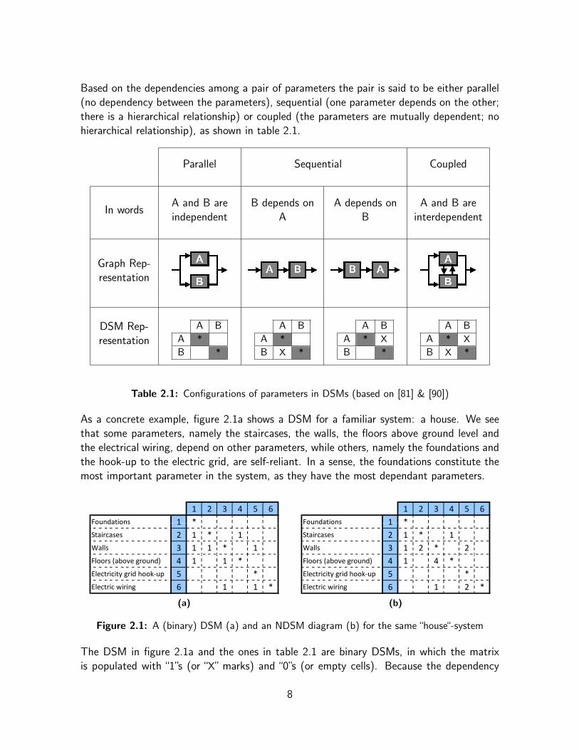
Based on the dependencies among a pair of parameters the pair is said to be either parallel(no dependency between the parameters), sequential (one parameter depends on the other;there is a hierarchical relationship) or coupled (the parameters are mutually dependent; nohierarchical relationship), as shown in table 2.1.
Parallel Sequential Coupled
In wordsA and B areindependent
B depends onA
A depends onB
A and B areinterdependent
Graph Rep-resentation
DSM Rep-resentation
A B
A *
B *
A B
A *
B X *
A B
A * X
B *
A B
A * X
B X *
Table 2.1: Configurations of parameters in DSMs (based on [81] & [90])
As a concrete example, figure 2.1a shows a DSM for a familiar system: a house. We seethat some parameters, namely the staircases, the walls, the floors above ground level andthe electrical wiring, depend on other parameters, while others, namely the foundations andthe hook-up to the electric grid, are self-reliant. In a sense, the foundations constitute themost important parameter in the system, as they have the most dependant parameters.
1
1 2 3 4 5 6
FoundationsFoundations 1 *
Staircases 2 1 * 1
Walls 3 1 1 * 1
Floors (above ground) 4 1 1 *
Electricity grid hookどup 5 *
Electric wiring 6 1 1 *
(a)
1
1 2 3 4 5 6
FoundationsFoundations 1 *
Staircases 2 1 * 1
Walls 3 1 2 * 2
Floors (above ground) 4 1 4 *
Electricity grid hookどup 5 *
Electric wiring 6 1 2 *
(b)
Figure 2.1: A (binary) DSM (a) and an NDSM diagram (b) for the same “house“-system
The DSM in figure 2.1a and the ones in table 2.1 are binary DSMs, in which the matrixis populated with “1”s (or “X” marks) and “0”s (or empty cells). Because the dependency
8
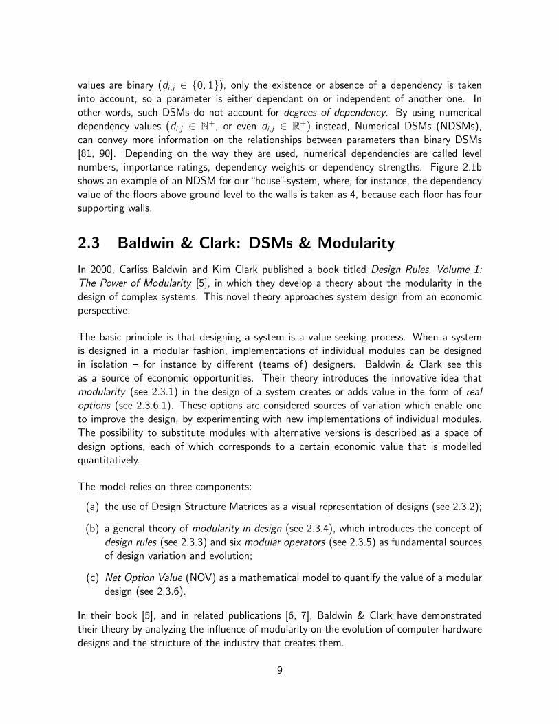
values are binary (di ,j ∈ {0, 1}), only the existence or absence of a dependency is takeninto account, so a parameter is either dependant on or independent of another one. Inother words, such DSMs do not account for degrees of dependency. By using numericaldependency values (di ,j ∈ N+, or even di ,j ∈ R+) instead, Numerical DSMs (NDSMs),can convey more information on the relationships between parameters than binary DSMs[81, 90]. Depending on the way they are used, numerical dependencies are called levelnumbers, importance ratings, dependency weights or dependency strengths. Figure 2.1bshows an example of an NDSM for our“house”-system, where, for instance, the dependencyvalue of the floors above ground level to the walls is taken as 4, because each floor has foursupporting walls.
2.3 Baldwin & Clark: DSMs & Modularity
In 2000, Carliss Baldwin and Kim Clark published a book titled Design Rules, Volume 1:The Power of Modularity [5], in which they develop a theory about the modularity in thedesign of complex systems. This novel theory approaches system design from an economicperspective.
The basic principle is that designing a system is a value-seeking process. When a systemis designed in a modular fashion, implementations of individual modules can be designedin isolation – for instance by different (teams of) designers. Baldwin & Clark see thisas a source of economic opportunities. Their theory introduces the innovative idea thatmodularity (see 2.3.1) in the design of a system creates or adds value in the form of realoptions (see 2.3.6.1). These options are considered sources of variation which enable oneto improve the design, by experimenting with new implementations of individual modules.The possibility to substitute modules with alternative versions is described as a space ofdesign options, each of which corresponds to a certain economic value that is modelledquantitatively.
The model relies on three components:
(a) the use of Design Structure Matrices as a visual representation of designs (see 2.3.2);
(b) a general theory of modularity in design (see 2.3.4), which introduces the concept ofdesign rules (see 2.3.3) and six modular operators (see 2.3.5) as fundamental sourcesof design variation and evolution;
(c) Net Option Value (NOV) as a mathematical model to quantify the value of a modulardesign (see 2.3.6).
In their book [5], and in related publications [6, 7], Baldwin & Clark have demonstratedtheir theory by analyzing the influence of modularity on the evolution of computer hardwaredesigns and the structure of the industry that creates them.
9
2.3.1 What is Modularity?
Baldwin & Clark define (in Chapter 3 of [5]) the concept of modularity using three subsidiaryideas. The first is the idea of interdependence within and independence across modules:
A module is a unit whose structural elements are powerfully connected amongthemselves and relatively weakly connected to elements in other units. Clearlythere are degrees of connection, thus there are gradations of modularity.
In other words, modules are units in a larger system that are structurally independent ofone another, but work together to perform the functions of system. The system as a wholemust therefore provide a framework – an architecture – that allows for both independenceof structure and integration of function.
The second and the third idea capture the connection of modularity with three other, closelyrelated, concepts: abstraction, information hiding and interface:
A complex system can be managed by dividing it up into smaller pieces (mod-ules) and looking at each one separately. When the complexity of one of theelements crosses a certain threshold, that complexity can be isolated by defininga separate abstraction that has a simple interface. The abstraction hides thecomplexity of the element; the interface indicates how the element interactswith the larger system.
When the complexity of one of the elements crosses a certain threshold, thatcomplexity can be isolated by defining a separate “abstraction” with simple in-terface. The abstraction “hides” the complexity of the element. ...
These general ideas align well with the notions of modularity, separation of concerns [18],abstraction, information hiding and interface that are common in software development.In fact, the principle of information hiding was first put forward in that context by DavidParnas [55, 56], but it is general enough to be applied to any complex system.
2.3.2 Representing Modularity in Designs using DSMs
1 2 3 4 5 6 7
Module 1A 1 * 1B 2 1 * 1 1
Module 2 C 3 * 1Module 3 D 4 1 *
Module 4
E 5 1 * 1F 6 1 1 1 *G 7 1 1 *
Figure 2.2: A DSM with highlighted modules
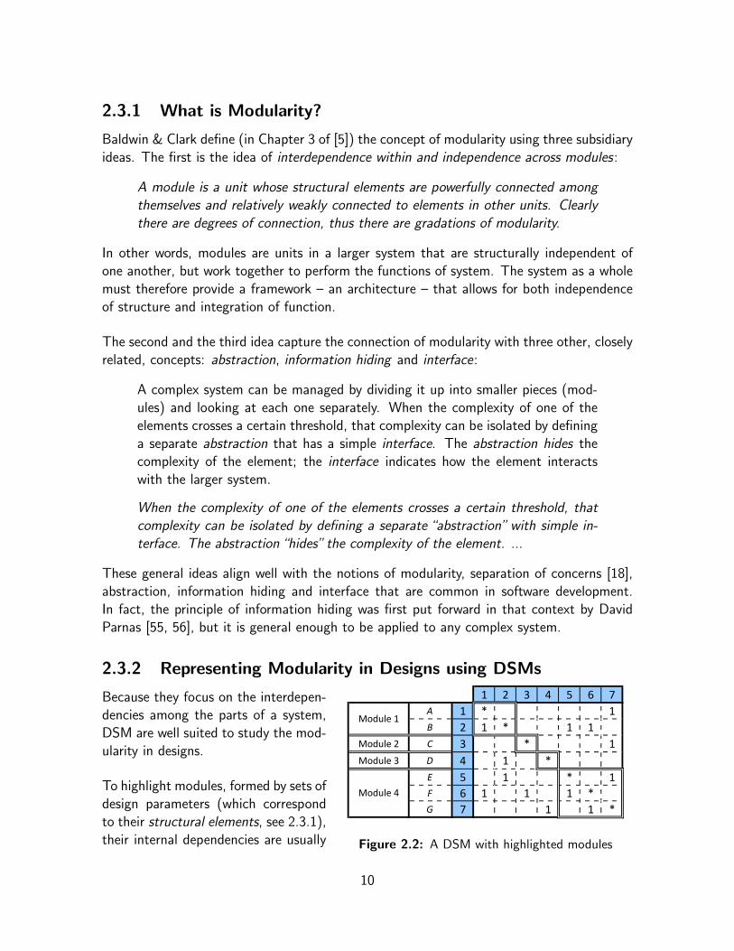
Because they focus on the interdepen-dencies among the parts of a system,DSM are well suited to study the mod-ularity in designs.
To highlight modules, formed by sets ofdesign parameters (which correspondto their structural elements, see 2.3.1),their internal dependencies are usually
10
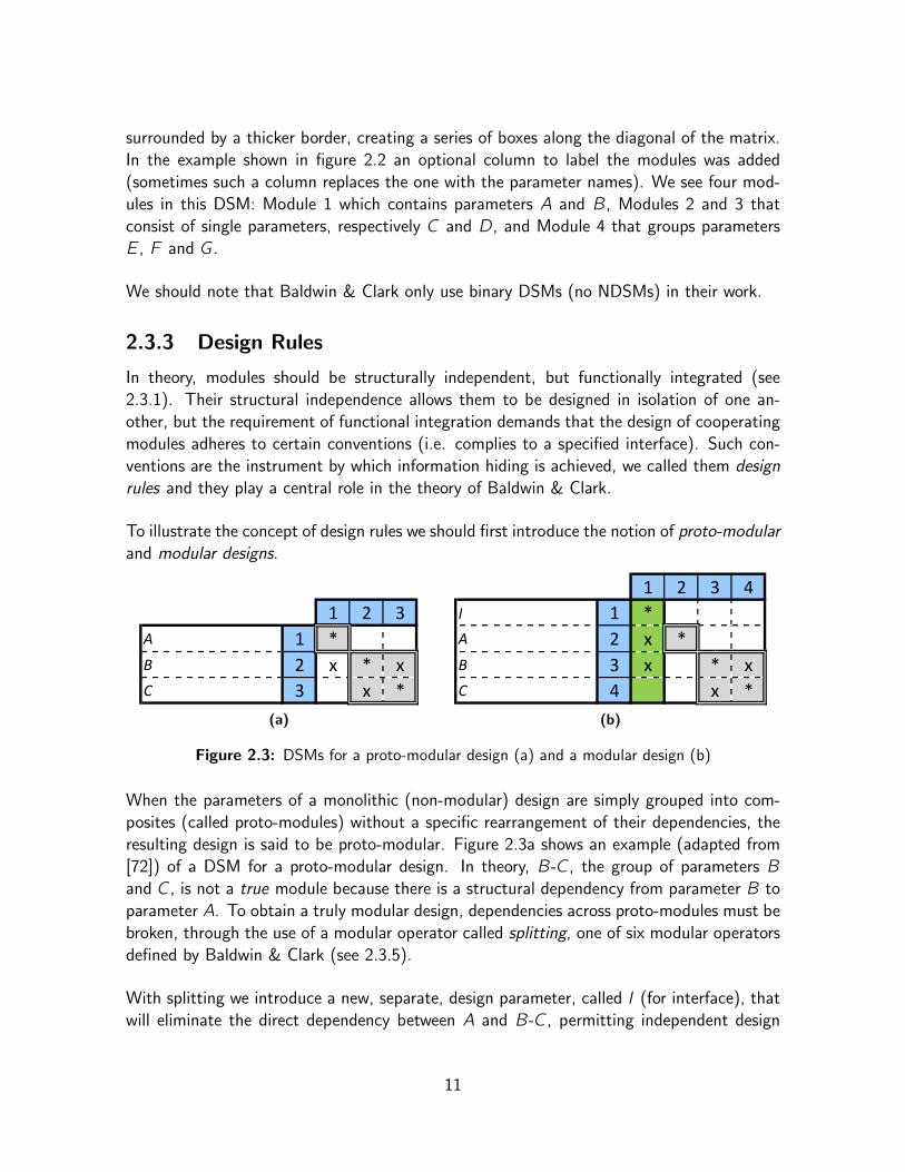
surrounded by a thicker border, creating a series of boxes along the diagonal of the matrix.In the example shown in figure 2.2 an optional column to label the modules was added(sometimes such a column replaces the one with the parameter names). We see four mod-ules in this DSM: Module 1 which contains parameters A and B, Modules 2 and 3 thatconsist of single parameters, respectively C and D, and Module 4 that groups parametersE, F and G.
We should note that Baldwin & Clark only use binary DSMs (no NDSMs) in their work.
2.3.3 Design Rules
In theory, modules should be structurally independent, but functionally integrated (see2.3.1). Their structural independence allows them to be designed in isolation of one an-other, but the requirement of functional integration demands that the design of cooperatingmodules adheres to certain conventions (i.e. complies to a specified interface). Such con-ventions are the instrument by which information hiding is achieved, we called them designrules and they play a central role in the theory of Baldwin & Clark.
To illustrate the concept of design rules we should first introduce the notion of proto-modularand modular designs.
1 2 3A 1 *B 2 x * xC 3 x *
(a)
1 2 3 4I 1 *A 2 x *B 3 x * xC 4 x *
(b)
Figure 2.3: DSMs for a proto-modular design (a) and a modular design (b)
When the parameters of a monolithic (non-modular) design are simply grouped into com-posites (called proto-modules) without a specific rearrangement of their dependencies, theresulting design is said to be proto-modular. Figure 2.3a shows an example (adapted from[72]) of a DSM for a proto-modular design. In theory, B-C, the group of parameters Band C, is not a true module because there is a structural dependency from parameter B toparameter A. To obtain a truly modular design, dependencies across proto-modules must bebroken, through the use of a modular operator called splitting, one of six modular operatorsdefined by Baldwin & Clark (see 2.3.5).
With splitting we introduce a new, separate, design parameter, called I (for interface), thatwill eliminate the direct dependency between A and B-C, permitting independent design
11
choices for both modules. The DSM of the resulting modular design is shown in figure 2.3b2.We see that B no longer depends on A and instead both A and B take on a hierarchicaldependency on the new parameter I. The latter dependency means that any value given tothe B parameter (corresponding to a implementation for B) is constrained to access A onlythrough the interface of A, represented by the value given to I. The former dependencysignifies that the value for A can change freely without affecting B, as long as it compliesto the interface of A, as specified by the value of I.
A chronological interpretation3 of the ordering of the parameters in the DSM shown by fig-ure 2.3b would demand that task I has been completed before tasks A, B and C are started.In other words, the designers first have to specify an interface for A, as a implementationof I, before modules A and B-C can be implemented. If the implementation of I is everchanged, the implementation of A and B will have to change as well, in order to comply tothe new interface.
A design parameter, such as I, that decouples otherwise dependent proto-modules, is calleda design rule. When a design rule is given a value, an assertion is made that that value isintended not to change. Therefore, design rules impose constraints that other parametersmust respect and which they can assume to be stable. In the theory of Baldwin & Clark,modularisation4 through the imposition of design rules is the key to constrain and structurethe design space and search process [72].
The terminology of Baldwin & Clark makes a distinction between visible and hidden mod-ules. Visible modules are modules that other modules depend on (they are “seen” by othermodules). Design rules, such as I, fall in this category. Modules are called hidden when noother modules depend on them and they only depend on design rules.
Software engineers will likely notice that this theoretical approach to specifying interfaces,grasped by the concept of design rules, is consistent with common practices in (object-oriented) software design.
2.3.4 Modularity in Design
Now we have introduced design rules, we can define modularity in design as follows [7]:
A complex engineering system is modular-in-design if (and only if) the processof designing it can be split up and distributed across separate modules, that arecoordinated by design rules, not by ongoing consultations amongst the designers.
2 The green box around the I column in figure 2.3b indicates that I is a design rule for this design.3 In 2.4.2 we will see that such an interpretation makes the diagram a time-based DSM.4 Modularisation can be defined as the evolution of a monolithical or proto-modular design to a modular
design. In that sense, a modularisation specifies one way of doing that.
12
2.3.5 Modular Operators
The splitting operator we used in 2.3.3 is one of six modular operators that Baldwin &Clark introduce to model design evolution of complex systems. The others are: substitution,augmentation, exclusion, inversion and porting. The operators act as fundamental sourcesof variation in modular designs.
As we have seen, the splitting operator splits (proto-)modules and serves to modulariseproto-modular designs. The other operators modify designs which are already modular. Byapplying the substitution operator the implementation of a module can be substituted fora new, adapted or improved one. In case of hidden modules substitution can take placewithout affecting other modules. The augmentation operator adds a module that was notpart of the system before and its complement, the exclusion operator, removes a modulefrom the system. The inversion operator standardises or collects common design elementsacross modules by organising the modules as a new hierarchical level. Finally, the portingoperator transports a module of use in another system by creating “shell” around it [7, 72].
2.3.6 Net Option Value of a Modular Design
Even with design rules, a true modular design cannot always be achieved and designers oftenhave a wide range of modularisations to choose from. Because not all modularisations areequally good (as there are gradations of modularity; see 2.3.1), it is useful to quantitativelyevaluate designs. Therefore, Baldwin & Clark support their theory with a novel statisticalmodel that reasons about the value added to a base system by modularity. This model,called Net Option Value (NOV), is based on the theory of real options and estimates theeconomic value of a modularly designed system by considering – in addition to other inputparameters – the dependencies among the modules in the design, as documented by a DSM.
2.3.6.1 Real Options
In finance, an option is an investment which provides the holder with the right to makeanother investment in the future (by exercising the option), without an obligation to makethat investment. Therefore, an option can have a positive payoff but never needs to havea negative one. Consequently, an option always has a positive present value, much like alottery ticket [72].
Linking the economic theory of real options with the concept of modularity, Baldwin &Clark observed that modularity in design both multiplies and decentralizes real options thatincrease the value of a design. In a non-modular system, a design can only be replaced as awhole and the authority to accept changes is centralized. The designer only has one option:the choice to either accept or reject the whole design. On the other hand, in a modularisedsystem, any or all modules can be redesigned and replaced independently. Here, replacement
13

decisions are decentralised: the designers responsible for modules can make substitutiondecisions without coordination. In this sense, modularity provides a portfolio of optionswhich, according to modern finance, always adds value [72].
2.3.6.2 NOV Formulae
We now provide a thorough explanation of the formulae of the NOV model. Table 2.2 showsa helpful overview and brief explanations of the symbols that appear in the equations below.
Symbol Name/Explanation
NOV (Total) Net Option Value of the system
S0 Base value of the unmodularised system, usually normalised to 0
novi Net Option Value of the i -th module
m Number of modules in the system
σi Technical potential of the i -th module
ni Complexity of the i -th module
ki The number of search/substitute experiments simulated for the i -th module
Ci(ni) The cost of one simulated search/substitute experiment on i -th module
(a function of ni), often taken as Ci(ni) = cini
ci Redesign cost of the i -th module
Zi Visibility cost to replace the i -th module
Q(k) Expected value of the best of k independent draws from a standard normal
distribution, for all positive values in the distribution (see Appendix A)
N(x) Standard normal cumulative distribution function (see Appendix A)
n(x) Standard normal probability density function (see Appendix A)
Table 2.2: NOV formulae legend
The NOV model estimates the economic value of a modular design by looking at the addedvalue generated by each module through the redesign option it represents. This is expressedby equation 2.1, which defines NOV , the (total) value of a design for a system.
NOV = S0 + nov 1 + nov 2 + ...+ novm (2.1)
This formula should be interpreted as follows: splitting a design into m modules – each ofwhich consists of a number (> 1) of design parameters – increases its base value, S0, bythe sum of the net option values (novi) of the resulting options. So for any i -th module,novi represents the value that the module contributes to NOV . These value contributionscorrespond to the opportunity each module i creates to invest in ki experiments to create
14
candidate replacements, each at a cost related to the complexity of the module, and, if anyof the results are better than the existing choice, to substitute in the best of them, at acost related to the visibility of the module to other modules [72].
Baldwin & Clark formalise the options value of each modular operator; for instance, howmuch is it worth to be able to substitute a module, augment it, exclude it, etc. So in fact,they define six formulas for novi , one for each modular operator. Additionally, they define asimpler, generic expression for novi , that values the option to redesign a module, no matterwhich modular operator is used. This expression is shown by equation 2.2.
nov i = max{ maxki{σi√niQ(ki)︸ ︷︷ ︸
Benef it
− Ci(ni)ki − Zi︸ ︷︷ ︸Investment
}; 0 } (2.2)
An overview of the formulae for all six operators is beyond the scope of this introduction toNOV, therefore we limit ourselves to this generic formula. However, for the sake of clarity,we explain it as if it only applies to the substitution operator5. In that sense, the formuladescribes the statistical simulation of search/substitute experiments. In the following para-graphs we present a breakdown of the formula, interpreted for the substitution operator.
Equation 2.2 takes novi , the net option value of the i -th module, as the maximum (positive)return value out of ki design experiments on the i -th module. In other words, it is the ex-pected payoff of exercising the search and substitute option for the i -th module optimally 6.The maximisation is achieved by the maxki function. This function iteratively incrementsthe number of (simulated) experiments ki (e.g.: from 0 to 10) to find the so-called break-even point. This is the value for ki that maximises the expected gain from the i -th module.The function then returns this maximal gain. Because usually only positive return valuesare taken into account [45], the first max function normalises negative novi values to 0.
The part of the formula within the braces of the maxki function corresponds to the expectedreturn value from the i -th module for a particular value of ki , accounting for both benefitand investment (option exercise costs).
The term σi√niQ(ki) represents the expected benefit to be gained by accepting the best
candidate – a replacement for the existing module – generated by ki independent experi-ments. The NOV model assumes this added value is a random variable normally distributedabout the value of the existing i -th module choice (normalised to 0), with a variance σ2i nithat reflects the technical potential σi and the complexity ni of the i -th module. The stan-dard deviation on the expected value is thus
√σ2i ni = σi
√ni . The term Q(ki), formulised
by equation 2.3, is the expected value of the best of ki independent draws from a standard
5 This is inspired by other authors who applied the NOV model in the context of software development[72, 73]; see Chapter 4 (section 4.3).
6 By balancing the profits of design improvements with the costs of experimenting and redesigning (seeeconomic principle of diminishing returns).
15

normal distribution, for all positive values in the distribution. Tabulated values of Q(ki)for 0 6 ki 6 100 can be found in Appendix A, along with additional information on thisstatistical distribution.
Q(k) = k
∞∫0
x [N(x)]k−1 n(x) dx (2.3)
Zi =∑
j sees i
cjnj (2.4)
The investment consists of an experimentation cost and a visibility cost. The first elementrepresents the cost incurred in doing the ki experiments on the i -th module and is expressedby Ci(ni)ki . The cost of a single experiment on that module is expressed as a function Ciof ni , the complexity of the module. This function is often, for instance in [45], taken asCi(ni) = cini , where ci is the redesign cost of the i -th module. The second investmentelement for the i -th module is its visibility cost, is given by Zi , which is computed byequation 2.4. This represents the cost to replace the i -th module, given the other modulesin the system that directly depend on (or “see”) it and the complexity nj and redesigncost cj of each of those. The Zi parameter is the place where the NOV model takes thedependencies among the modules, as documented in a DSM, into account.
2.3.6.3 NOV Calculation Example
To clarify how the NOV formulae work, we return to the “house”-system example fromsection 2.2. The NOV of a design for a system can be calculated straightforwardly usinga spreadsheet7. The one shown in figure 2.4 computes the NOV for the design of thehouse, as visualised by the (binary) DSM in figure 2.1a, where each individual parameter isinterpreted as a module.
тnov
experiments
) т 0 0 0 1
Return value out of ki (0 г ki г 6)
i ゝi Zi ci nki т 0 1 2 3 4 5 6
maxiQ(k )Q(ki 0 000. 00 00000 .3989 03989 .68106810 0 8881.8881 1 0458 1 1697 1 2701
ik1.0458 1.1697 .2701
Foundations 1 2.5 0.575 1 0.225 ど0.575 ど0.3269 ど0.2174 ど0.1968 ど0.2349 ど0.3129 ど0.4189 ど0.19678693 0.000000
Staircases 2 2.5 0.1333 1 0.175 ど0.1333 0.10889 0.22891 0.27051 0.26034 0.21497 0.14494 0.270513286 0.270513
Walls 3 2.5 0.4 1 0.1333 ど0.4 ど0.1692 ど0.045 0.01076 0.02131 0.00112 ど0.0406 0.021306476 0.021306
Floors (above ground) 4 2.5 0.175 1 0.2667 ど0.175 0.07337 0.17088 0.17159 0.1084 0.00175 ど0.1353 0.17159316 0.171593
Electricity grid hookどup 5 2.5 0.2667 1 0.0667 ど0.2667 ど0.0758 0.03961 0.10663 0.1417 0.15504 0.15316 0.155041243 0.155041
Electric wiring 6 2.5 0 1 0.1333 0 0.23085 0.35503 0.41076 0.42131 0.40112 0.35941 0.421306476 0.421306
NOV т 1.03976
ki
Figure 2.4: NOV calculation for the DSM in figure 2.1a
The first column of the spreadsheet shows the names of the modules. The next five columnslist the values, per i -th module, of the input parameters of the NOV calculation. In thisexample, the technical potential, σi , is assumed to be 2.5 for every module; the visibility
7 Because setting up NOV spreadsheets manually is a tedious job, we created a tool to automate theprocess. We discuss this tool in Chapter 3.
16

cost, Zi , is computed according to equation 2.4, by consulting the DSM in figure 2.1a toknow which modules depend on (or “see”) the module; the cost of an experiment on amodule, Ci(ni), is taken as cini ; the redesign cost, ci , is set at 1 for every module and thecomplexities of the modules, ni , are given values that sum to 1 and supposedly reflect therelative complexity of the parts of our imaginary house.
The middle part of the spreadsheet covers the search/substitute experiments. For everyi -th module the expected return value (benefit minus investment) out of ki experiments iscomputed for 0 6 ki 6 6. The benefits (given by σi
√niQ(ki)) increase with ki . How-
ever, the experimentation cost (given by ciniki) also increases with ki and eventually thesearch/substitute experiments will meet diminishing returns. Consequently, after reachingthe break-even point, the value for ki that maximises the return value, higher values of kiwill decrease the return value. The spreadsheet highlights the return value at the break-evenpoint of every module in green. The second-to-last column of the spreadsheet implementsthe maxki function; it selects the return value at the break-even point for each module. Thelast column copies those values but normalises negatives to 0, giving novi . Finally, all novivalues are summed giving NOV , the total net option value for the design of the house.
0.2
0.4
0.6
Return value out of ki experiments for each module
Foundations
‐0.8
‐0.6
‐0.4
‐0.2
0
0 1 2 3 4 5 6
Number of Experiments (ki)
Staircases
Walls
Floors (above ground)
Electricity grid hook‐up
Electric wiring
Figure 2.5: Graphed return values for ki design experiments on each module from figure 2.4
As an illustration, figure 2.5 graphs the return value for every module from figure 2.4 infunction of the number of search/substitute experiments. The peak in the curve for aspecific module indicates the break-even point for that module.
17

The graph and the spreadsheet clearly show that the sixth module, which represents theelectric wiring, reaches the highest return value (on its break-even point at k6 = 4) of allthe modules. Hence, the module adds the most to NOV . The high return values of thismodule are caused by its lack of dependent modules (nothing depends on the electric wiring,hence the visibility cost Z6 is 0) and its low relative complexity (given by n6).
It also stands out that the first module, which represents the foundations, has the lowestreturn values. Because the investments outweigh the benefits (of finding better designs forthe foundations), for any number of experiments (so for every value of k1), the return valuesfor the module are negative across the board. This is even the case at its break-even point(at k1 = 3), which causes nov1 it to be normalized to 0. Consequently, this module addsnothing to NOV . The low return values are due to the large number of dependents (threeother modules depend on the foundations, resulting in a high visibility cost, given by Z1)and the high relative complexity (given by n1).
2.3.6.4 Strength and Weakness
The strength of NOV is that its mathematical expressions tie together modular dependencies,uncertainty and economic theory in a cohesive model [45].
However, the NOV model is not a black box. Its application in a particular field requiresmaking assumptions, appropriate for the given context, about the input parameters used inthe NOV calculation. Attributing different values to these parameters will obviously changethe outcome of the NOV calculation, even when the design of the system, represented bya DSM, remains the same. As an illustration, figure 2.6 shows a new spreadsheet thatagain computes the net option value for the DSM in figure 2.1a, but uses different values,compared to the spreadsheet in figure 2.4, for the redesign cost of the fifth and the sixthmodule. The result is a 55% increase of NOV .
тnov
experiments
) т 0 0 0 1
Return value out of ki (0 г ki г 6)
i ゝi Zi ci nki т 0 1 2 3 4 5 6
maxiQ(k )Q(ki 0 000. 00 00000 .3989 03989 .68106810 0 8881.8881 1 0458 1 1697 1 2701
ik1.0458 1.1697 .2701
Foundations 1 2.5 0.575 1 0.225 ど0.575 ど0.3269 ど0.2174 ど0.1968 ど0.2349 ど0.3129 ど0.4189 ど0.19678693 0.000000
Staircases 2 2.5 0.1333 1 0.175 ど0.1333 0.10889 0.22891 0.27051 0.26034 0.21497 0.14494 0.270513286 0.270513
Walls 3 2.5 0.3667 1 0.1333 ど0.3667 ど0.1358 ど0.0116 0.0441 0.05464 0.03446 ど0.0073 0.054639809 0.054640
Floors (above ground) 4 2.5 0.175 1 0.2667 ど0.175 0.07337 0.17088 0.17159 0.1084 0.00175 ど0.1353 0.17159316 0.171593
Electricity grid hookどup 5 2.5 0.2333 0.25 0.0667 ど0.2333 0.00752 0.17294 0.28996 0.37503 0.43837 0.4865 0.486495024 0.486495
Electric wiring 6 2.5 0 0.75 0.1333 0 0.26418 0.4217 0.51076 0.55464 0.56779 0.55941 0.567789566 0.567790
NOV т 1.55103
ki
Figure 2.6: NOV calculation for the DSM in figure 2.1a, using adjusted values for c5 and c6
A weakness of the NOV model is that the meaning of its parameters in a given context canbe unclear, which makes assumptions for their values hard to justify. For example, how doesone measure the“technical potential”of a staircase? Clearly, the meaning of the parameters
18

in a given context needs to be determined before the model can confidently applied. Thesame is true for NOV , the outcome of the computation. For instance, it is unlikely that anarchitect knows what a net option value of 1.03976 signifies for the house he is designing.
This turns out to be an important issue when applying DSMs and NOV in the context ofsoftware development, as we discuss in Chapter 4.
Another remark we should make is that the NOV model might not be suitable to be combinedwith NDSMs. Anyhow, we can assume that it was not designed for that purpose, sinceBaldwin & Clark only use it with regular, binary, DSMs throughout their publications (asnoted in 2.3.2).
2.4 Overview of Applications
This section provides a broad outline of some of the applications of DSMs that have beendeveloped in engineering at large and in other fields. This is not intended as a thoroughsurvey, but rather as a brief introduction to ongoing research into applications of DSMs.
2.4.1 Roles of DSMs
According to [91], a DSM is both a project management tool and system analysis tool.In the role of a project management tool a DSM is primarily used to diagram informationflows in complex projects. As a system analysis tool DSMs are used to analyse processesand architectures of products or organisations. However, there is no clear boundary betweenboth roles, as specific applications of DSMs can combine them.
2.4.1.1 Project Management Tool
The Design Structure Matrix has its origins in project management [67, 68] and is still usedin that context by large corporations such as General Motors, Boeing, Airbus and Intel.Project management applications of DSMs continue to receive interest from the researchcommunity as well [19, 81].
In these applications, DSMs represent the constituent stages, tasks or activities of an engi-neering project, along with the corresponding dependencies. The dependencies define theinput which is required to start a certain activity and the generated output that needs tofeed into other activities. Both input and output represent pieces of information. Hence,the pattern of dependencies in the DSM explicitly describes the exchange of informationthat is vital to the project. Such DSM-based project representations result, usually afterbeing analysed and restructured with special algorithms (see 2.4.2), in an improved andmore realistic execution schedule for the corresponding activities [91].
19
Traditional project management tools, such as PERT charts, Gantt charts and Critical Pathmethods (CPM)8, were created to model and manage sequential and parallel processes con-sisting of discrete tasks that make up large construction projects. They capture work flow,often using pre and post conditions (e.g.: “Which tasks must be completed before task Xcan start?”), but do not to track the flow of information (e.g.: “Which pieces of informationare needed before task X can succeed?”).
According to the adepts of DSMs [19, 81], these tools are not suitable for managing largeinnovative projects because they fail to address the inherent complexity of such projects. Forexample, the design and development of complex “high-tech” products commonly requiresa collaboration between a large number of participants from diverse backgrounds, resultingin complex relationships among both people and tasks. These relationships involve interde-pendencies (e.g.: task sequencing, feedback, cyclic dependencies, iterations, ...) which arehard to represent with tools lacking support for tracking information flow.
Compared to conventional project management tools, DSMs focus on representing infor-mation flows rather than work flows. Therefore, the DSM method, which is essentially aninformation exchange model, enables managers and product development planners to dealwith the complex relationships in large engineering projects [19, 81].
2.4.1.2 System Analysis Tool
DSMs can also be applied as a tool to analyse complex systems. Analysed system ar-chitectures can be for both tangible (e.g.: material products) and intangible things (e.g.:projects or organisations). The compact and clear representation DSMs provide facilitatesthe capturing and understanding of interactions, interdependencies and interfaces betweenthe elements of the system, such as subsystems or modules. Moreover, the diagrams canhighlight key processes and enable engineers to discover previously unknown patterns inarchitectures. The diagrams can also show where staff members fit in the larger project ororganisation they are part of [90].
2.4.2 Types of DSMs
Tyson Browning [14, 15, 90] distinguishes four different types of DSM applications, basedon the kind of data that is represented. He also introduced two main categories if DSMs:static and time-based. Figure 2.7 shows a taxonomy of the categories and types of DSMsaccording to Browning.
In static DSMs the parameters represent the elements of a system that exist simultaneously,such as components of a product architecture or groups of people in an organisation. Intime-based DSMs the parameters represent activities or processes, and their ordering in the
8 Refer to [51] for an in-depth introduction to these and other conventional project management tools.
20
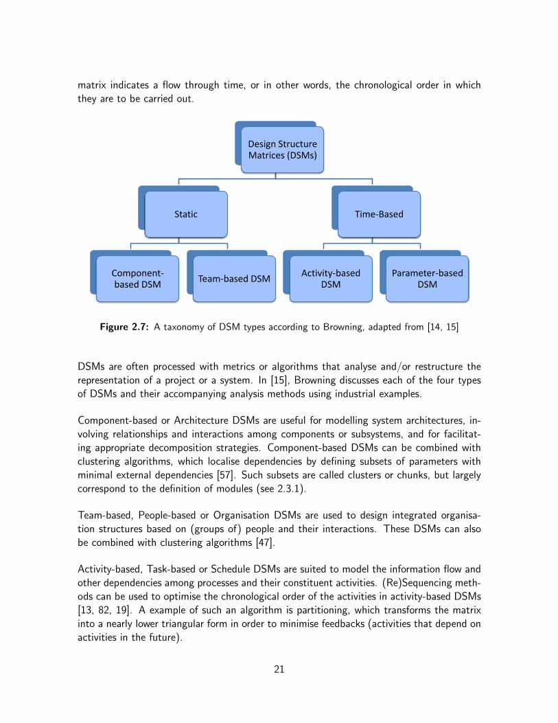
matrix indicates a flow through time, or in other words, the chronological order in whichthey are to be carried out.
Design Structure Matrices (DSMs)
Static
Component-based DSM
Team-based DSM
Time-Based
Activity-based DSM
Parameter-based DSM
Figure 2.7: A taxonomy of DSM types according to Browning, adapted from [14, 15]
DSMs are often processed with metrics or algorithms that analyse and/or restructure therepresentation of a project or a system. In [15], Browning discusses each of the four typesof DSMs and their accompanying analysis methods using industrial examples.
Component-based or Architecture DSMs are useful for modelling system architectures, in-volving relationships and interactions among components or subsystems, and for facilitat-ing appropriate decomposition strategies. Component-based DSMs can be combined withclustering algorithms, which localise dependencies by defining subsets of parameters withminimal external dependencies [57]. Such subsets are called clusters or chunks, but largelycorrespond to the definition of modules (see 2.3.1).
Team-based, People-based or Organisation DSMs are used to design integrated organisa-tion structures based on (groups of) people and their interactions. These DSMs can alsobe combined with clustering algorithms [47].
Activity-based, Task-based or Schedule DSMs are suited to model the information flow andother dependencies among processes and their constituent activities. (Re)Sequencing meth-ods can be used to optimise the chronological order of the activities in activity-based DSMs[13, 82, 19]. A example of such an algorithm is partitioning, which transforms the matrixinto a nearly lower triangular form in order to minimise feedbacks (activities that depend onactivities in the future).
21
Finally, Parameter-based or Low-Level Schedule DSMs are aimed at modelling and integrat-ing low-level design decisions and processes based on physical design parameter relationships.A noteworthy example can be found in the work of Black et al. who applied parameter-basedDSMs to an automobile brake system design [9].
2.5 Conclusions
In this chapter we provided an extensive introduction to Design Structure Matrices (DSMs),the central subject of this dissertation.
The presentation of the theory of Baldwin & Clark, about the economic aspects of modu-larity in the design of complex systems, covered the best part of the chapter. We gave anoverview of the principle elements of the theory: Baldwin & Clark’s theoretical approach tomodularity, the use of DSMs to visualize modular designs, the concept of design rules andmost importantly, the Net Option Value (NOV) model. We explained and demonstratedhow this mathematical model can be applied to a DSM representation of a design for asystem, to quantitatively assess the economic value of that design.
We also paid attention to the many existing applications of DSMs, primarily in the field ofengineering.
In the remainder of this dissertation we present our research into applications of DSMs andrelated techniques such as NOV. Chapter 3 introduces a tool we developed to facilitateexperimentation with DSMs and the NOV model. In the following chapters we focus onapplications of DSMs in the context of software development. Chapter 4 presents an as-sessment of the novel aspect-oriented software development (AOSD) paradigm, which wascarried out using the tool from Chapter 3. Chapter 5 deals with our research into DSM-basedsupport tools for object-oriented software development (OOSD) and introduces a prototypeof such a tool. Finally, in Chapter 6 presents a number of real-world usage scenarios forthat prototype.
22
Chapter 3
DSM+NOV Tool
In this chapter we introduce DSM+NOV Tool, a simple yet powerful application we de-veloped to support experiments with DSMs and the NOV model. As far as we know, thisis the first software of its kind. The main functionality of this tool is the automated gen-eration of convenient spreadsheets that contain a DSM and handle all NOV calculations.We primarily created this application to generate the DSM+NOV spreadsheets we usedto conduct a qualitative assessment of aspect-oriented and object-oriented design patternimplementations, which we discuss in the next chapter.
3.1 Introduction
In Chapter 2 we introduced the combination of Design Structure Matrices (DSMs) with theNet Option Value (NOV) model, as proposed by Baldwin & Clark [5]. This combination,which we will refer to as the DSM+NOV methodology, is promising for quantitative assess-ments of designs in diverse contexts. But the computations involved in the NOV model aretoo complex to be performed manually. However, as far as we know, there is no special-purpose software in existence today that handles NOV calculations1, which clearly hampersexperimentation with the DSM+NOV methodology.
This was problematic because we wanted to use the methodology to conduct a large-scalequalitative assessment of Aspect-Oriented and Object-Oriented Design Pattern implemen-tations, which we discuss in Chapter 4. Therefore, we developed an application of our own,named DSM+NOV Tool, which we present here.
We first set out some requirements in section 3.2. Next, section 3.3 presents our approach,the automated generation of DSM+NOV spreadsheets. Then, section 3.4 gives an overviewof the features and specific details of the application. Section 3.5 concludes the chapter.
1 In Chapter 5 (section 5.5) we discuss the few DSM-related software tools we know of. However, noneof these support NOV computation.
23
3.2 Requirements
The purpose of the application is twofold. On the one hand it should facilitate explorationof and experiments with the DSM+NOV methodology itself. On the other hand, in viewof the work we present in Chapter 4, it should facilitate actual assessments of designs.Additionally, it should be a general-purpose tool, allowing the methodology to be applied invarious fields.
3.3 Approach
Spreadsheets are an obvious way to automate NOV calculations. In Chapter 2 we showedan example spreadsheet (see figure 2.4) that implements the NOV formulae. We also no-tice that other authors [45, 46] follow this approach. If the DSM itself is added to sucha spreadsheet the formulas for NOV calculation can be hooked up to it. That way, it iseasy to experiment with different dependency patterns and adjusted values for NOV inputparameters because the results are immediately visible.
However, even when templates are used, setting up such spreadsheets manually is a tediousjob. Every time one needs to analyse a new system – with a different number of modules –or every time the number of simulated experiments must to be extended, all formulas needto be adjusted. This is both boring and prone to error.
To resolve this problem, we created an application, named DSM+NOV Tool [66], that gen-erates ready to use customised DSM+NOV spreadsheets. The application was implementedas an add-in for Microsoft Excel [96] written in Visual Basic for Applications [104].
3.4 DSM+NOV Tool
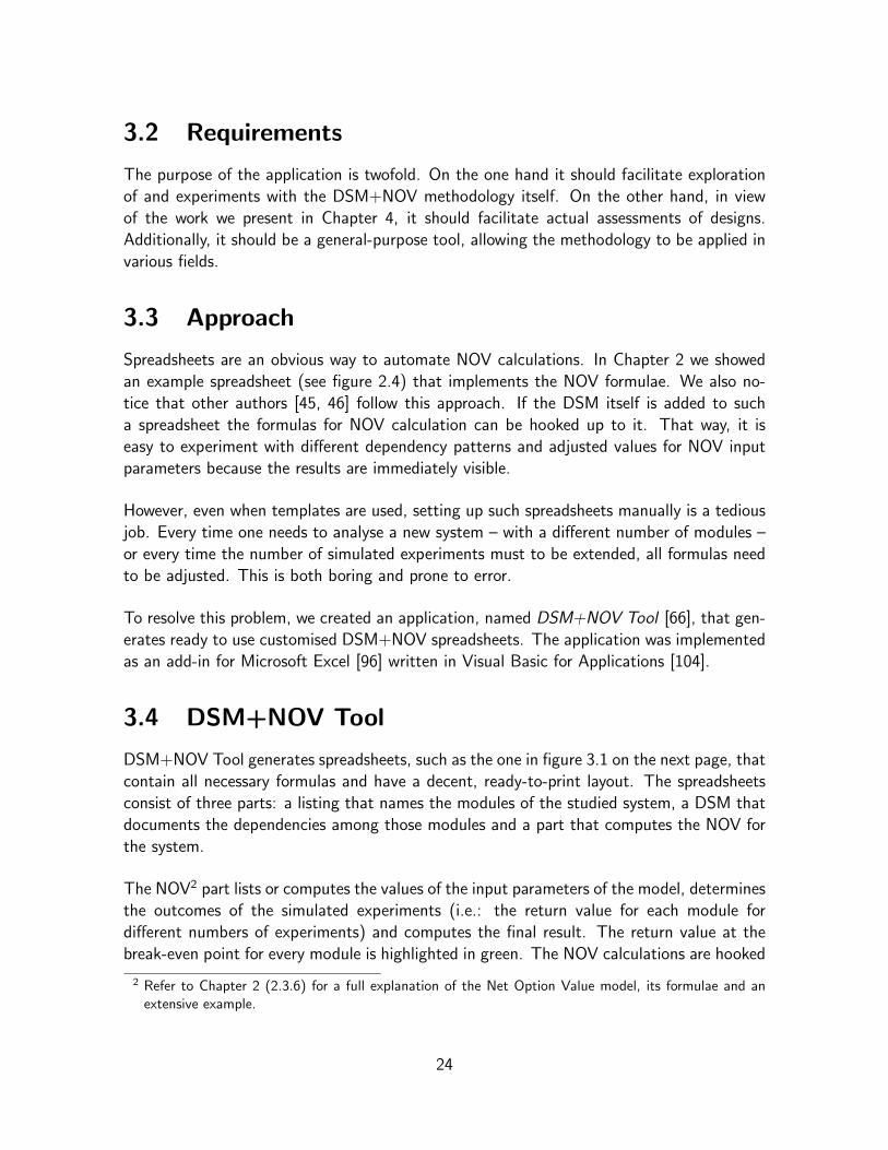
DSM+NOV Tool generates spreadsheets, such as the one in figure 3.1 on the next page, thatcontain all necessary formulas and have a decent, ready-to-print layout. The spreadsheetsconsist of three parts: a listing that names the modules of the studied system, a DSM thatdocuments the dependencies among those modules and a part that computes the NOV forthe system.
The NOV2 part lists or computes the values of the input parameters of the model, determinesthe outcomes of the simulated experiments (i.e.: the return value for each module fordifferent numbers of experiments) and computes the final result. The return value at thebreak-even point for every module is highlighted in green. The NOV calculations are hooked
2 Refer to Chapter 2 (2.3.6) for a full explanation of the Net Option Value model, its formulae and anextensive example.
24
up to the DSM, in which the dependencies need to be filled out manually, through the valuesof the Z parameter, the visibility cost. Further details on the computation of this parameterand on other choices with regard to NOV calculation are provided in 3.4.1.
max nov
NOV Results
DSM+NOV Tool Demo
Modules DSM NOV Analysis
NOV Parameters Simulation of 4 Experiments
3 4ゝ Z p c n
k т 0 1 2 3 4
1 2 Q(k) т 0.0000 0.3989 0.6810 0.8881 1.0458
Module 1 (not in NOV) 1 * 1 1 1
Module 2 2 1 * 2.5 0.5 2 1 0.33333333 ど0.5 ど0.2575 ど0.1837 ど0.2181 ど0.3239 ど0.18367432 0.000000
Module 3 3 1 * 2.5 0 3 1 0.5 0 0.20524 0.20391 0.07004 ど0.1513 0.205236979 0.205237
Module 4 4 1 * 2.5 0 1 1 0.16666667 0 0.2405 0.36175 0.40646 0.40065 0.406461483 0.406461
N т 6 п т 1 NOV т 0.611698
Figure 3.1: Example of a generated spreadsheet
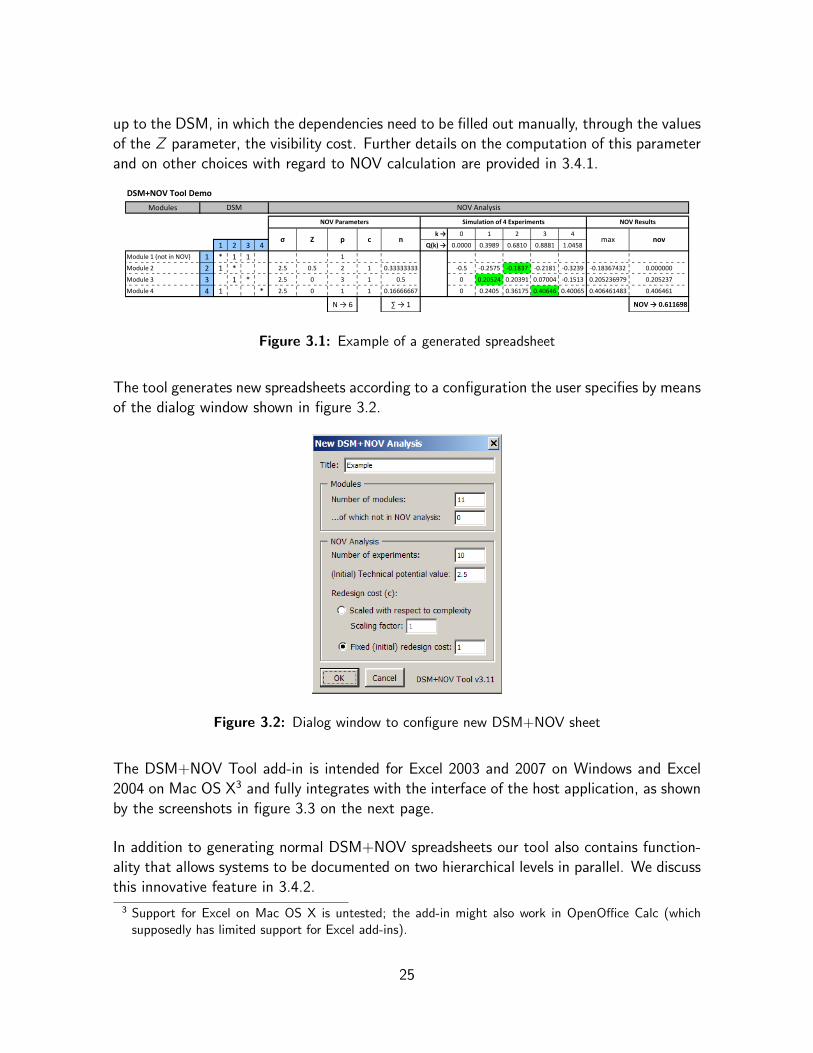
The tool generates new spreadsheets according to a configuration the user specifies by meansof the dialog window shown in figure 3.2.
Figure 3.2: Dialog window to configure new DSM+NOV sheet
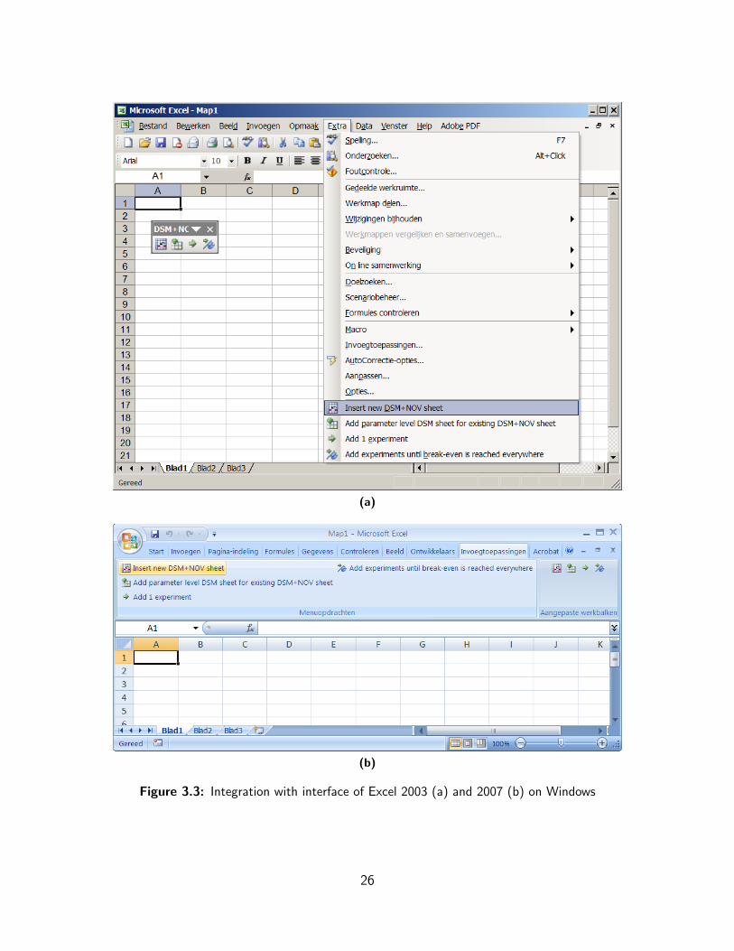
The DSM+NOV Tool add-in is intended for Excel 2003 and 2007 on Windows and Excel2004 on Mac OS X3 and fully integrates with the interface of the host application, as shownby the screenshots in figure 3.3 on the next page.
In addition to generating normal DSM+NOV spreadsheets our tool also contains function-ality that allows systems to be documented on two hierarchical levels in parallel. We discussthis innovative feature in 3.4.2.
3 Support for Excel on Mac OS X is untested; the add-in might also work in OpenOffice Calc (whichsupposedly has limited support for Excel add-ins).
25
(a)
(b)
Figure 3.3: Integration with interface of Excel 2003 (a) and 2007 (b) on Windows
26

3.4.1 Net Option Value Calculation
Here we list the most important choices for our implementation of the NOV model.
One of the options in the configuration dialog (see figure 3.2) allows users to exclude anumber of modules from the NOV calculation. As shown in the example spreadsheet (seefigure 3.1) NOV-exclusion is indicated in the name of such modules. The intention is toallow users to employ a DSM which includes dependencies from parts of the studied systemto external entities which are not an integral part of the system, without affecting the NOVresults. The inspiration for this feature comes from Sullivan et al. [72]4, who introducedEnvironment and Design Structure Matrices (EDSMs), a DSM variant extended with thenotion of environment parameters (EPs).
The configuration dialog lets users specify the number of simulated experiments. However,because it can be hard to estimate beforehand the number of experiments that is needed toreach a break-even point for every module, our tool can also insert additional experimentcolumns into earlier generated spreadsheets. Users can choose to add experiments one byone or they can use the automatic break-even points finding feature, which adds experimentsuntil the return value of all modules is decreasing (i.e.: until each module has reached itsbreak-even point).
Currently our tool uses the generic formula to compute the net option value for each mod-ule. Future versions of the tool could offer the user a choice between the specific formulaefor each of the six modular operators defined by Baldwin & Clark5.
To compute the return value of ki simulated experiments on each i -th module the value ofQ(ki) needs to be known. However, computing that value involves integrations (see Ap-pendix A), which Microsoft Excel cannot handle. Therefore our application uses a numericalintegration algorithm. The code was taken from XNumbers [107], an open source librarythat extends Excel with support for numerical methods.
Zi =∑
j sees i
cjnj =
i−1∑j=1
dj,icjnj +
m∑j=i+1
dj,icjnj (3.1)
The visibility cost parameter, Z, links NOV calculation to the dependencies in the DSM.For the i -th module, it is computed according to equation 3.1. Where m is the numberof modules in the system, cj and nj are respectively the redesign cost and the complexityof a j-th module and dj,i is the value on the j-th row and the i -th column in the DSM,corresponding to a dependency from the j-th module to the i -th module. Dependenciesfrom excluded modules are discarded, as cj and nj equal to 0 for those modules.
4 We discuss the work of Sullivan et al. in Chapter 4 (section 4.3).5 Refer to Chapter 2 (2.3.5) for an explanation on substitution and the other five modular operators.
27

Users can freely adjust the values of the remaining NOV input parameters for each module.But DSM+NOV Tool provides default settings which follow conventions and assumptionsproposed by Baldwin & Clark or by authors that have applied the NOV model in the contextof software development6:
• The technical potential of each i -th module, σi , defaults to 2.5;
• The redesign cost of each i -th module, ci , is either fixed at 1 or taken as a userspecified factor (which defaults to 1) that is scaled with respect to ni , the complexityof that module;
• The complexity of each i -th module, ni , is taken as the number of design parameterscontained in the module, pi , divided by N, the total number of design parameters inthe system (ignoring those in NOV-excluded modules);
• The number of design parameters in each i -th module, pi , defaults to 1.
3.4.2 Module- and Parameter-level DSMs
The generation of parameter-level DSMs is the most innovative feature of DSM+NOV Tool.The goal is to allow dependencies occurring on a lower hierarchical level of the studied systemto be documented and taken into consideration by the NOV calculation. To explain thisfeature we first need to recapitulate the difference between design parameters and modules.
Design Parameters and ModulesIn Chapter 2 we explained that a DSM confronts design parameters to document the de-pendencies among them. Design parameters correspond to discrete structural elements inthe design of the studied system. A module groups a set of design parameters, which are(expected to be) strongly dependant on each other but relatively weakly dependant on de-sign parameters outside the module. Figure 3.4 reproduces the example we have used toshow how DSM diagrams can be extended to visualise modules.
1 2 3 4 5 6 7
Module 1A 1 * 1B 2 1 * 1 1
Module 2 C 3 * 1Module 3 D 4 1 *
Module 4
E 5 1 * 1F 6 1 1 1 *G 7 1 1 *
Figure 3.4: A DSM with modules consisting of design parameters
6 Refer to Chapter 4 (section 4.3).
28
Conceptually both modules and (design) parameters represent parts of the studied system,but on different levels or layers of hierarchy, detail, abstraction or granularity. For example,when studying an object-oriented software system, modules could represent classes, whileparameters could represent methods.
Module-level DSMsThe NOV model evaluates the design of a system based on properties of the modules in thatsystem and the dependencies among those. In other words, NOV only looks at dependencieson the module level. Therefore, the DSMs in our generated spreadsheets differ from regularones because they confront modules instead of design parameters and thus only documentdependencies among modules.
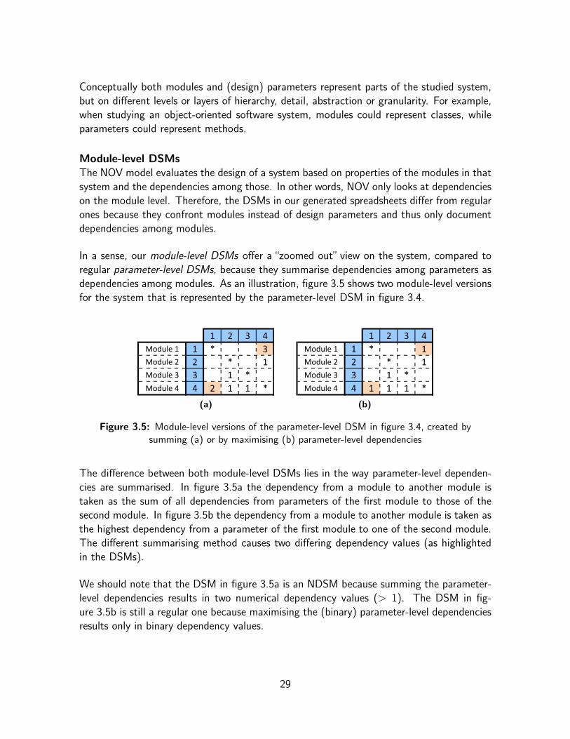
In a sense, our module-level DSMs offer a “zoomed out” view on the system, compared toregular parameter-level DSMs, because they summarise dependencies among parameters asdependencies among modules. As an illustration, figure 3.5 shows two module-level versionsfor the system that is represented by the parameter-level DSM in figure 3.4.
1 2 3 4Module 1 1 * 3Module 2 2 * 1Module 3 3 1 *Module 4 4 2 1 1 *
(a)
1 2 3 4Module 1 1 * 1Module 2 2 * 1Module 3 3 1 *Module 4 4 1 1 1 *
(b)
Figure 3.5: Module-level versions of the parameter-level DSM in figure 3.4, created bysumming (a) or by maximising (b) parameter-level dependencies
The difference between both module-level DSMs lies in the way parameter-level dependen-cies are summarised. In figure 3.5a the dependency from a module to another module istaken as the sum of all dependencies from parameters of the first module to those of thesecond module. In figure 3.5b the dependency from a module to another module is taken asthe highest dependency from a parameter of the first module to one of the second module.The different summarising method causes two differing dependency values (as highlightedin the DSMs).
We should note that the DSM in figure 3.5a is an NDSM because summing the parameter-level dependencies results in two numerical dependency values (> 1). The DSM in fig-ure 3.5b is still a regular one because maximising the (binary) parameter-level dependenciesresults only in binary dependency values.
29

Combining Module- and Parameter-level DSMsWhen using our application, we must fill out the DSM with dependencies on the level ofmodules, so if the studied system has a meaningful lower hierarchical level, we must eitherignore it or manually summarise relevant dependencies occurring on that level. In eithercase, we lose a degree of detail because the parameter-level dependencies are not explicitlydocumented.
To resolve this problem, DSM+NOV Tool includes a feature that enables users to simulta-neously document dependencies occurring on two hierarchical levels. This novel approachcalculates the NOV of a system based on the combination of a module-level DSM and aparameter-level DSM.
The procedure is as follows. Starting off with a regular generated DSM+NOV spreadsheetthe user must specify the number of design parameters contained in each i -th module, byadjusting the value of pi . Next, the user can let the tool generate a parameter-level DSM– as a second spreadsheet – with the right number of parameters per module. In there, theparameter-level dependencies can be filled out, as illustrated by figure 3.6b.
To take the parameter-level dependencies into account for NOV calculation, the tools linksboth DSMs by inserting summarizing formulas into the dependency cells of the original,
NOV Results
nov
Module level
Modules DSM NOV Analysis
NOV Parameters Simulation of 8 Experiments
4ゝ Z p c n
k т 0 4 5 6 8max
1 2 3 Q(k) т 0.0000 1.0458 1.1697 1.2701 1.4242
Module 1 1 * 1 2.5 0.45 1 0.5 0.1 ど0.45 0.1767 0.2247 0.2541 0.2759 0.27589156 0.275892
Module 2 2 1 * 2 1 2.5 0.7 3 0.5 0.3 ど0.7 0.132 0.1517 0.1391 0.0501 0.15168435 0.151684
Module 3 3 1 3 * 2 2.5 0.5 4 0.5 0.4 ど0.5 0.3535 0.3495 0.3082 0.1518 0.35348465 0.353485
Module 4 4 1 1 2 * 2.5 0.6 2 0.5 0.2 ど0.6 0.1692 0.2078 0.22 0.1923 0.21998437 0.219984
N т 10 п т 1 NOV т 1.001045
(a)
1 1 * 1
Parameter level
Modules Parameters DSM
1 2 3 4 5 6 7 8 9 10
Module 1Module Parameter 1 1Parameter 1.1 1 * 1
Module 2
Parameter 2.1 2
*
1
Parameter 2.2 3 1
Parameter 2.3 4 1 1
Module 3
Parameter 3.1 5 1
*Parameter 3.2 6 1
Parameter 3.3 7 1 1
Parameter 3.4 8 1 1
Module 4Parameter 4.1 9 1 1
*Parameter 4.2 10 1 1
(b)
Figure 3.6: NOV calculation for a module-level DSM (a) which summarises dependencies ina parameter-level DSM (b) by summing
30
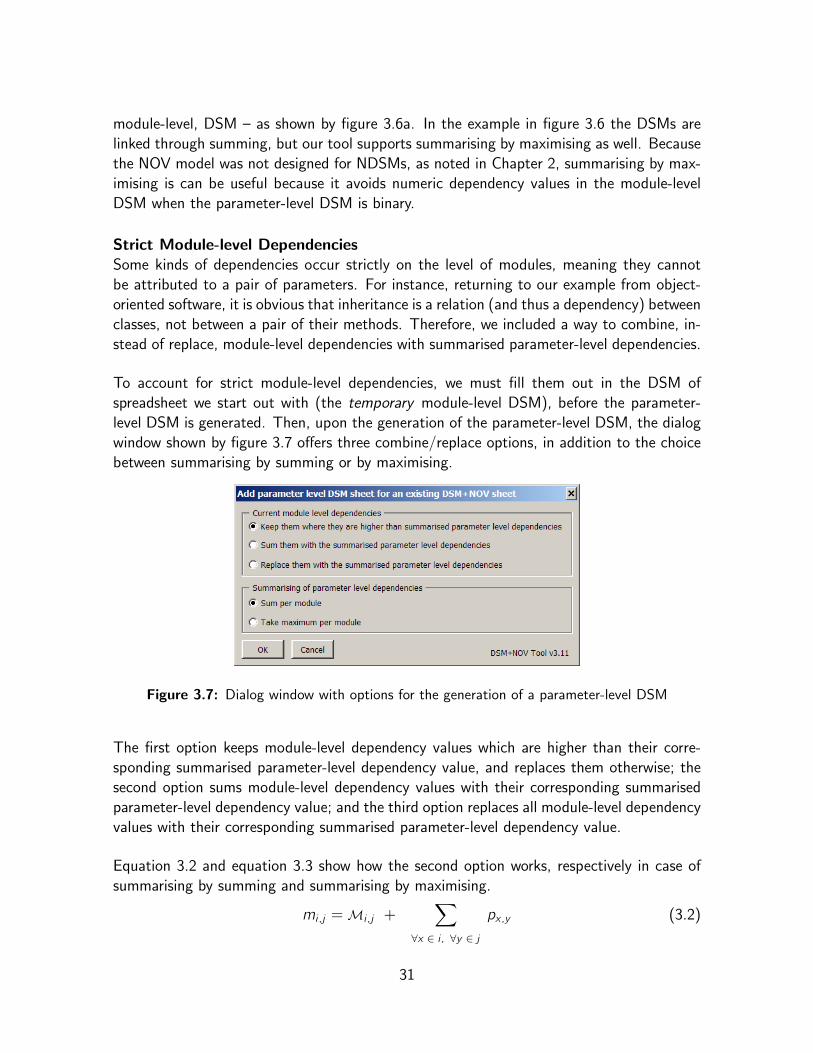
module-level, DSM – as shown by figure 3.6a. In the example in figure 3.6 the DSMs arelinked through summing, but our tool supports summarising by maximising as well. Becausethe NOV model was not designed for NDSMs, as noted in Chapter 2, summarising by max-imising is can be useful because it avoids numeric dependency values in the module-levelDSM when the parameter-level DSM is binary.
Strict Module-level DependenciesSome kinds of dependencies occur strictly on the level of modules, meaning they cannotbe attributed to a pair of parameters. For instance, returning to our example from object-oriented software, it is obvious that inheritance is a relation (and thus a dependency) betweenclasses, not between a pair of their methods. Therefore, we included a way to combine, in-stead of replace, module-level dependencies with summarised parameter-level dependencies.
To account for strict module-level dependencies, we must fill them out in the DSM ofspreadsheet we start out with (the temporary module-level DSM), before the parameter-level DSM is generated. Then, upon the generation of the parameter-level DSM, the dialogwindow shown by figure 3.7 offers three combine/replace options, in addition to the choicebetween summarising by summing or by maximising.
Figure 3.7: Dialog window with options for the generation of a parameter-level DSM
The first option keeps module-level dependency values which are higher than their corre-sponding summarised parameter-level dependency value, and replaces them otherwise; thesecond option sums module-level dependency values with their corresponding summarisedparameter-level dependency value; and the third option replaces all module-level dependencyvalues with their corresponding summarised parameter-level dependency value.
Equation 3.2 and equation 3.3 show how the second option works, respectively in case ofsummarising by summing and summarising by maximising.
mi ,j =Mi ,j +∑
∀x ∈ i , ∀y ∈ j
px,y (3.2)
31
mi ,j =Mi ,j + max
∀x ∈ i , ∀y ∈ j
px,y (3.3)
In the equations:
• mi ,j , Mi ,j and pi ,j are respectively dependency values in the final module-level DSM,the temporary module-level DSM and the parameter-level DSM;
• i and j are modules, with i 6= j ;
• x and y are design parameters, respectively contained in module i and module j .
3.5 Conclusions
DSM+NOV Tool significantly reduces the time one needs spend to prepare a DSM+NOVspreadsheet and thus clearly satisfies the requirements set out in section 3.2.
We believe the tool is a valid technical contribution to the field because it facilitates theapplication of the DSM+NOV methodology to concrete design assessments as well as ex-ploration of and experimentation with the methodology itself. This is illustrated by thework we present in Chapter 4, which deals with comparative assessments, carried out usingDSM+NOV Tool, of object-oriented and aspect-oriented software designs. The tool hasalso been shared with other researchers7.
As far as we know, the idea to base NOV calculation on a combination of two DSMs, whichdocument dependencies on different hierarchical levels, is a novel concept in the field. InChapter 4 we demonstrate how we used this innovative feature to document implementationdependencies in software on two granularity levels.
7 Namely Cristina Lopes and Sushil Bajracharya, whose work we discuss in Chapter 4 (section 4.3).
32

Chapter 4
Assessing Aspect-Orientation usingDSMs and NOV
In this chapter we present an evaluation of DSMs and the NOV model as a methodologyfor quantitative assessment of modularity in software designs. To experiment with thismethodology, we apply it to aspect-oriented and object-oriented implementations of theGoF design patterns, in order to assess the claimed modularisation advantages of the novelaspect-orientation paradigm. Based on those experiments we formulate critiques on theapplicability of the NOV model as a modularity metric for software design.
4.1 Introduction
In Chapter 2 we introduced Design Structure Matrices (DSMs) and the Net Option Value(NOV) model [5]. We believe that the combination of both techniques is a promisingmethodology for quantitative assessments of designs in diverse contexts. In this chapter,we present our research into the application of this DSM+NOV methodology as a toolfor quantitative assessment and comparison of software designs. Specifically, we aim toevaluate whether or not the NOV model can serve as a metric to quantify modularity insoftware designs. By extension, we want to investigate whether NOV can help to validateor invalidate the claims of software development paradigms with regard to modularisationproperties.
Inspired by the work of others [44, 45, 73], we took the opportunity to link this researchto the Aspect-Oriented Software Development (AOSD) field. The novel aspect-orientationparadigm claims to provide improved modularisation properties over the object-orientationparadigm. This makes aspect-orientation an interesting subject for our evaluation of NOVas a modularity metric.
In summary, we want to evaluate the merits of NOV as a modularity metric, by employingthe DSM+NOV methodology to carry out a quantitative assessment of the modularisation
33
properties of the aspect-orientation paradigm, in comparison with the object-orientationparadigm. As a concrete case study, we choose to compare aspect-oriented and object-oriented implementations of the GoF design patterns [22], respectively written in AspectJand Java [24].
We present experiments on AspectJ and Java versions of three design patterns. The exper-iments were carried out using the DSM+NOV spreadsheet generation tool we introduced inChapter 3. Based on the results of these experiments we formulate conclusions and critiqueson the applicability of NOV as a modularity metric for software.
In this chapter, we first provide an elaborate introduction to the aspect-orientation paradigmin section 4.2. Next, in section 4.3 we discuss the work of others who have applied DSMsand NOV in the context of software development. Further, in section 4.4 we provide a briefintroduction to design patterns. Then, section 4.5 deals with the experiments we conductedand formulates observations based on the results. We conclude this chapter in section 4.6.
4.2 Aspect-Oriented Software Development
In its quest for higher software quality and lower development and maintenance costs, soft-ware development is constantly evolving. In its history of over 60 years, the discipline hasseen many different paradigms with accompanying programming languages and design tech-niques. Since the days of machine-level assembly languages, the procedural, functional andobject-oriented programming paradigms have been introduced (among others). Each newparadigm provides new abstraction mechanisms and language features over older paradigms,allowing improved design and implementation structures, which ideally lower overall com-plexity and increase reusability.
One of the latest developments in the evolution of programming is the rise of Aspect-Oriented Programming (AOP), a novel paradigm which was introduced by Gregor Kiczalesin the second half of the 1990s [32, 36, 37]. Aspect-orientation (AO) builds further uponthe concepts of object-orientation (OO) – and older paradigms – but focuses on providingmechanisms to enable the modularisation of so-called crosscutting-concerns (see 4.2.1 and4.2.2) by means of aspectual decomposition (see 4.2.3).
Aspect-Oriented Software Development (AOSD) is the broader paradigm devoted to apply-ing the concepts of aspect-orientation to the whole software development lifecycle.
In the remainder of this section we will introduce the most important concepts of aspect-orientation. Further introductory reading on AOSD can be found in [12], upon which thissection is based. An elaborate account on the history of AOSD is provided in [43].
34
4.2.1 Modularisation1 and Separation of Concerns
The power of an abstraction mechanism is that it provides a means of modularisation, whichallows software to be structured in separate, cooperating, modules. Modularisation helpssoftware engineers achieve what is called the separation of concerns (SoC).
This principle, originally introduced by Dijkstra [18], is one of the driving ideas of theevolution of software development paradigms. In the context of software development, aconcern is defined as an interest which pertains to the system’s development, its operationor any other matters that are critical or otherwise important to one of the stakeholders [75].A concern of a software application can be related to both functional (e.g.: as captured byuse cases) and non-functional (e.g.: reliability, scalability, ...) requirements.
The principle of separation of concerns demands that every concern is treated in isolationthroughout the development lifecycle. This means that each concern should be modelled,designed and implemented as a separate unit or module. Thereby the complexity of individualmodules is reduced and it is ensured that each module represents a well-defined subpart ofthe system, corresponding to a single concern. This results in improved evolvability andreusability of the application and its parts. Such properties help to keep software projectsmanageable, which can ultimately lead to lower development and maintenance costs.
In object-orientation modularisation is achieved by decomposing software applications intoindividual units called objects. Ideally any single concern is represented by a particulargroup of such objects. There are, however, concerns which cannot be modularised usingthe techniques the OO paradigm provides. Enabling the modularisation of such crosscuttingconcerns is the main goal of the AO paradigm.
4.2.2 Crosscutting Concerns
Common examples of crosscutting concerns include synchronisation policies, error and excep-tion handling, enforcement of real-time constraints, security requirements, logging, tracingand fault tolerance mechanisms. Without a paradigm that explicitly handles such cross-cutting concerns, their implementation causes scattering and tangling with respect to theimplementation of other concerns.
Scattering is defined as the occurrence of the representation of one concern in multiplemodules [75]. Tangling, on the other hand, is defined as the occurrence of representationsof multiple concerns mixed together in a single module [75]. Both issues tend to appeartogether; they describe different facets of the same problem.
To illustrate scattering and tangling, we will show how they manifest themselves in the
1 Refer to Chapter 2 (2.3.1) for general definitions of modularity, modules and modularisation.
35
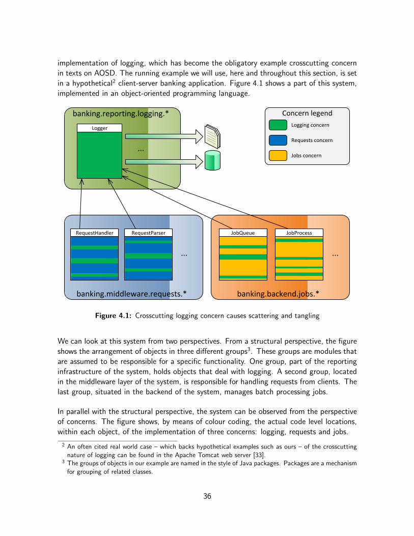
implementation of logging, which has become the obligatory example crosscutting concernin texts on AOSD. The running example we will use, here and throughout this section, is setin a hypothetical2 client-server banking application. Figure 4.1 shows a part of this system,implemented in an object-oriented programming language.
banking.middleware.requests.*
...
RequestHandler RequestParser
banking.backend.jobs.*
...
JobProcessJobQueue
Concern legendLogging concern
Jobs concern
Requests concern
banking.reporting.logging.*
Logger
...
Figure 4.1: Crosscutting logging concern causes scattering and tangling
We can look at this system from two perspectives. From a structural perspective, the figureshows the arrangement of objects in three different groups3. These groups are modules thatare assumed to be responsible for a specific functionality. One group, part of the reportinginfrastructure of the system, holds objects that deal with logging. A second group, locatedin the middleware layer of the system, is responsible for handling requests from clients. Thelast group, situated in the backend of the system, manages batch processing jobs.
In parallel with the structural perspective, the system can be observed from the perspectiveof concerns. The figure shows, by means of colour coding, the actual code level locations,within each object, of the implementation of three concerns: logging, requests and jobs.
2 An often cited real world case – which backs hypothetical examples such as ours – of the crosscuttingnature of logging can be found in the Apache Tomcat web server [33].
3 The groups of objects in our example are named in the style of Java packages. Packages are a mechanismfor grouping of related classes.
36
It is clear that the implementation of the requests concern and the jobs concern is limited tothe respective groups of objects. However, the implementation of the logging concern is notlimited to objects in the logging group, on the contrary, there are bits of logging code in theobjects that deal with the requests and jobs concerns as well. In terms of the definitions, thelogging concern crosscuts the banking application as its representation is scattered (“spreadout”) over multiple modules and tangled (“mixed”) with the representation of other concernswithin individual modules.
We can conclude that object-oriented modularisation achieves the separation of the requestsand jobs concerns, but fails to do so for the logging concern. Because the banking software isrequired to log diverse operations occurring in different parts of the system, including thosethat deal with requests and jobs, any object-oriented implementation will always, regardlessof the chosen decomposition into objects, introduce logging code – which includes at leasta method call to a logging object – at the location of every operation that must be logged.Hence, the implementation of logging will be distributed across multiple modules, causingscattering and tangling and making it a crosscutting concern.
Crosscutting concerns like logging are common in most software systems and developersmight see them as being harmless. However, crosscutting concerns can be detrimentalbecause they break the principle of separation of concerns: single modules can contain theimplementation of multiple concerns (tangling) and crosscutting concerns lack a separate,explicit, representation (scattering). These issues hinder reuse and evolvability of bothcrosscutting and non-crosscutting concerns, which can be particularly harmful, especially inlarge-scale projects. The aspect-orientation paradigm provides a remedy for this problem byintroducing new modularisation mechanisms that enable developers to explicitly representcrosscutting concerns as separate entities.
Although we have discussed scattering and tangling in an object-oriented application, itis important to note that the problem of crosscutting concerns is not limited to object-orientation, it can be observed in other paradigms as well. The truth is there are alwaysrestrictions on the ability to modularly represent particular concerns. These restrictions areintrinsic to the decomposition technique dictated by the paradigm [74].
4.2.3 Aspectual Decomposition & Aspects
Pre-AO paradigms have always relied on functional (de)composition. In [37], Gregor Kicza-les pointed out that the resulting modules (e.g.: subroutines, procedures, functions, ADTs,components, objects) can be seen as generalised procedures. In order to modularise crosscut-ting concerns aspect-orientation introduces a fundamentally new modularisation technique,which is based on aspectual (de)composition. The resulting modules, representing cross-cutting concerns, are called aspects and are no longer generalized procedures.
37

The difference lies in the invocation mechanism. The behaviour of (generalised) proceduresis always explicitly invoked by other procedures. In contrast, aspects have an implicit invo-cation mechanism. This means their behaviour is implicitly invoked at specific points in theimplementation of other modules. Strictly speaking, the programmers of other modules donot need to be aware of the crosscutting concern and its implementation as an aspect4.
To achieve implicit invocation, aspects needs to specify themselves where or when their be-haviour needs to be invoked. An aspect does this by autonomously observing the executionof the (base) program: when specific patterns of actions occur it can execute additionalbehaviour on its own. Following the common terminology [75], the actions of the baseprogram are called join points, the patterns that describe sets of such join points are knownas pointcut( designator)s and the additional behaviour is referred to as advice (code).
In most AOP languages aspect implementations consist of two conceptually different parts:the functionality code, consisting of advices, which define the behaviour that is executedupon the invocation of the aspect, and the applicability code, consisting of pointcuts, whichdetermine where or when these invocations must occur. The join point model of the lan-guage defines the possible kinds of join points (e.g.: method or constructor calls, fieldreferences, etc.) and how they can be described by (“matched”) pointcuts.
We will illustrate the difference between explicit and implicit invocation and the basic AOconcepts using our running example. We assume the RequestHandler object includes threeoperations that need to be logged: operation X, Y and Z. Figure 4.2, on the next page,shows an object-oriented (a) and an aspect-oriented (b) implementation.
In the object-oriented implementation, each of the operations is followed by code that ex-plicitly invokes (e.g.: by means of a method call) the behaviour of the Logger object andthus implements part of the logging concern within the RequestHandler object (causingscattering and tangling). In an aspect-oriented implementation no logging code is presentin RequestHandler (avoiding scattering and tangling). Instead the new Logging aspect im-plements the logging behaviour, using advice code, and defines where it should be applied,by means of pointcuts that intercept operations X, Y and Z in RequestHandler and implicitlyinvoke the logging behaviour at those join points.
In conclusion, we should note that programs written in aspect-oriented languages require aspecial kind of compilers (or interpreters), called weavers. At compile-time, such weaversinsert the advice code at join points, as specified by pointcuts.
4 This principle is called obliviousness [20].
38

banking.middleware.requests.*
...Operation XLog operation X
Operation Y
Log operation Y
Operation ZLog operation Z
RequestHandler
banking.reporting.logging.*
Logger
...
(a)
banking.middleware.requests.*
...Operation X
Operation Y
Operation Z
RequestHandler
banking.reporting.logging.*
...
At Operation X in banking.middleware.requests.RequestHandler do...
At Operation Y in banking.middleware.requests.RequestHandler do...
At Operation Z in banking.middleware.requests.RequestHandler do...
Logging
an Aspect
(b)
Figure 4.2: Explicit invocation in an OO implementation (a) and implicit invocation in anAO implementation (b) of the logging concern
4.2.4 AspectJ
AspectJ, an aspect-oriented superset of Java [94, 23], is definitely the most prominent andmature AOP language today. It was created at Xerox PARC, by a team of researchers ledby Gregor Kiczales [34, 35]. The language is popular in the research community but receivesmajor interest from mainstream software development as well [16, 50]. Further developmentis now organised as an open-source project led by the Eclipse Foundation [88]. The sameorganisation also develops the AspectJ Development Tools (AJDT) [85], which extend theEclipse development environment with full-blown support for AspectJ.
In AspectJ, aspects can be expressed in much the same way as class definitions in Java, theycan include methods, advices and pointcut definitions. Join points in AspectJ are points inthe execution of a base program written in Java(/AspectJ), such as calls to or executionsof methods or constructors, exception throwing, field access, etc.
As a brief demonstration of the basic features, we will show how the logging concern from our
39

running example can be implemented using AspectJ. But first, let us look at a Java imple-mentation of the object-oriented solution from figure 4.2a: we see that the RequestHandlerclass, shown in box 4.1, implements part of the logging concern by ending the methods Op-erationX, OperationY and OperationZ with explicit invocations (on lines 9, 15 and 21)of the logging behaviour, implemented in the Logger class (not shown).� �
1 package banking.middleware.requests;2 import banking.reporting.logging .*;3
4 public class RequestHandler5 {6 public void OperationX ()7 {8 //...do stuff9 Logger.logLine("Operation X was carried out!");
10 }11
12 public void OperationY ()13 {14 //...do stuff15 Logger.logLine("Operation Y was carried out!");16 }17
18 public void OperationZ ()19 {20 //...do stuff21 Logger.logLine("Operation Z was carried out!");22 }23 }� �
Box 4.1: RequestHandler class
In an AspectJ/Java implementation of the aspect-oriented solution from figure 4.2b, wewould strip the logging code from the RequestHandler class (removing lines 9, 15 and 21from box 4.1) and combine it with an aspect like the one shown in box 4.2.� �
1 package banking.reporting.logging;2
3 public aspect Logging4 {5 private void logLine(String line) { /* ... */ }6
7 pointcut operationX () : execution(void banking.middleware.requests.RequestHandler.OperationX ());
8
9 after() : operationX ()10 {11 logLine("Operation X was carried out");12 }13
14 after() : execution(void banking.middleware.requests.RequestHandler.OperationY ())
15 {16 logLine("Operation Y was carried out");17 }18
19 after() : execution(void banking.middleware.requests.RequestHandler.OperationZ ())
20 {21 logLine("Operation Z was carried out");22 }23 }� �
Box 4.2: Logging aspect
40

The Logging aspect in box 4.2 implements the logging concern as a single module. It con-tains 3 advices that do the logging, each is triggered by a different pointcut that interceptsthe execution of one of the operations that need to be logged.
AspectJ pointcuts match specific join points using a regular expression, here we see threeexecution pointcuts that match the execution of a method or a constructor. The pointcutscan be named or anonymous. Named pointcuts (like the one on line 7) can be referred tofrom one or more advices (as on line 9). Anonymous pointcuts can only be used by a singleadvice as they are defined directly in the header of the advice (as on lines 14 and 19).
The advices in this example are after advices, meaning they run advice code after the joinpoint. In our case this means that operations X, Y and Z will be logged after their executionhas finished. Other advice kinds supported by AspectJ include before and around. Theformer runs advice code before the join point and the latter runs it instead of the join point,in which case the original join point can be executed with the proceed keyword.
More information on the AspectJ language can be found in [16, 38, 50, 83, 84, 86].
4.2.5 The Fragile Pointcut Problem
The implicit invocation mechanism introduced by the aspect-orientation paradigm effec-tively facilitates the modularisation of crosscutting concerns. However, that does not meanthat dependencies are eliminated. In fact, because pointcuts impose assumptions on thebase code, implicit invocation through pointcut definitions merely reverses the direction ofexisting dependencies. This is the root cause of the fragile pointcut problem5.
To illustrate this, we return to our logging example, as implemented in Java and AspectJ inboxes 4.1 and 4.2. We see that three explicit invocations of Logger.logLine in the Re-
questHandler class, are replaced by pointcuts in the Logging aspect, which are triggeredby the execution of the OperationX, -Y and -Z methods of RequestHandler. As a conse-quence, the explicit dependencies from these methods to Logger.logLine are replaced byimplicit dependencies in the opposite direction, from the pointcuts of the Logging aspectto the methods. These pointcuts impose a number of assumptions of the base code whichmake them fragile with respect to changes in the base code. For instance, our pointcutsexplicitly reference the methods by their full signature. When the base code evolves and themethod signatures change, the pointcuts will no longer match and the logging behaviourwill not be invoked, which effectively breaks the functionality of the program.
Exposing detrimental dependencies caused by fragile pointcuts in aspect-oriented softwaredesigns is one of the things we hope to achieve by applying the DSM+NOV methodology.
5 Tackling the fragile pointcut problem is one of the current hot topics in the AOSD research field[39, 69, 27, 29].
41
4.3 Related Work
Baldwin & Clark have a background in economy and in their publications [5, 6, 7] they takea broad view on engineering in general. Nevertheless their work has generated interest in thefield of computer science, most likely due to their explicit focus on the theoretical conceptof modularity, which has been a hot topic in computer science for nearly forty years.
In this section we give an overview of publications on the application of the DSM+NOVmethodology of Baldwin & Clark, in the context of computer science and software devel-opment in particular. Specifically, we discuss the work of a team of researchers headed byKevin Sullivan6 and of Cristina Lopes and Sushil Bajracharya.
Sullivan et al.The first application of the DSM+NOV methodology in the context of software was pre-sented by Sullivan et al. [72] in 2001. The paper presents an analysis, using DSMs, NOVand design rules7, of the Key Words in Context program, which was originally introducedby Parnas to show the importance of modularity in software [56].
The authors noted that DSMs, as used by Baldwin and Clark and in earlier work, do notallow to model the environment in which a design is embedded. To resolve this problemthey introduced Environment and Design Structure Matrices (EDSMs), which extend theDSM concept with the notion of environment parameters (EPs). EPs represent entitiesexogenous to the system, meaning that the designer does not control them, as opposed toconventional design parameters (DPs), which are endogenous to the system.
Furthermore, Sullivan et al. reported that making justifiable estimates for the input param-eters of the NOV model in the context software design remained an open challenge.
In 2005, Sullivan et al. applied the DSM+NOV methodology in the context of AOSD [73].In that publication they proposed a new kind of information hiding interface for aspect-orientation, which abstracts crosscutting behaviour by establishing design rules which ex-plicitly define the interface between aspects and base code entities.
Lopes & BajracharyaIn 2005, Lopes & Bajracharya published a short report [4] containing a list of open issuesconcerning the application of the NOV model in the context of software.
6 Sullivan also published on applying real option theory – see Chapter 2 (2.3.6) – to software design[70, 71].
7 Refer to Chapter 2 (2.3.3) for an explanation of the concept of design rules.
42

Some of the listed issues are:
• How can the numeric value from NOV be associated with meaningful attributes insoftware development?
• Is there a valid mapping between conventional software metrics and the parametersof NOV?
• How can differences between various forms of modular dependencies be incorporatedin the model? For example, in object-oriented software, should inheritance have thesame dependency weight as a method call?
The report concluded that a deeper understanding of the parameters in NOV, especially thelink between economic and software-related properties, was needed before such questionscould be answered. During our own research, as we discuss in the remainder of this chapter,we have run into many of the same questions.
Later in 2005, Lopes & Bajracharya demonstrated the use of the DSM+NOV methodologyto analyse and compare OO and AO implementations of a single, real-world application [44].Starting from an OO version they produced an AO version of the design in a step-by-stepfashion. The analysis of the different evolutions of the design showed that the AO designsyielded higher NOV scores than the OO versions. This led the authors to conclude that,under the theory of modularity of Baldwin & Clark, certain AO modularisations can addvalue to a design.
In 2006, Lopes & Bajracharya published an updated version [45] of their 2005 paper [44].This time they used another assumption for the technical potential parameter of the NOVmodel. Furthermore, to illustrate that AO modularisations are not by definition betterthan OO modularisations, they included an additional AO version of their running example,which was intentionally badly designed. In that case the increased usage of aspects had adetrimental effect on the NOV of the design.
This last publication is the most complete account of an effort to evaluate and compareOO and AO designs using the DSM+NOV methodology. Hence, it was the main source ofinspiration for the work we present in this chapter.
4.4 Design Patterns
Design patterns are general, repeatable solutions to a commonly occurring problems in (soft-ware) design. A design pattern is not a finished design but rather a description or templatestipulating how to solve a particular problem, applicable in many different situations.
43
The concept of design patterns was first introduced in the field of architecture and urbanplanning in the late 1970s [1]. In 1987, Kent Beck and Ward Cunningham began experi-menting with the idea of applying design patterns to software [8].
The publication of Design Patterns – Elements of Reusable Object-Oriented Software [22]by the Gang-of-Four (GoF ) in 1994, caused the popularity of design patterns in softwaredevelopment to surge. This standard work provides a comprehensive catalogue of flexibleobject-oriented solutions to common software design problems. Each of the GoF patternshas a name that is easy to remember, a detailed, yet sufficiently abstract, problem descrip-tion, and a solution expressed in terms of generalised classes and/or interfaces.
4.4.1 Aspect-Oriented Design Patterns
In 2002, Jan Hannemann & Gregor Kiczales published an article on design pattern imple-mentations in Java and AspectJ [24, 25]. They implemented all 23 GoF patterns in bothlanguages. In the AspectJ versions they redesigned the patterns to maximally exploit theAO features of the language. These design pattern implementations are the subject of theexperiments we present in this chapter.
To evaluate their work Hannemann & Kiczales qualitatively compared the pattern imple-mentations using 4 criteria: locality, reusability, composability and (un)pluggability. Theauthors concluded that in terms of these criteria AspectJ yielded a better implementationthan Java for 17 of the 23 design patterns.
4.5 Experiments
In these experiments we use the DSM+NOV methodology to compare aspect-oriented andobject-oriented implementations of GoF design patterns [22]. These experiments are acase study to try out the methodology and to evaluate the merits of the NOV model as amodularity metric for software design.
The design pattern implementations of Hannemann & Kiczales [24] are an excellent subjectfor qualitative comparison of designs, because the AspectJ and Java versions are identicalin functionality but differ significantly in design.
The GoF have categorised their design patterns in three groups: Behavioural, Creational andStructural design patterns. For the sake of representativeness we conducted DSM+NOVexperiments on the Java and AspectJ implementations of one pattern from each category,respectively the Observer, Builder and Composite design patterns.
Before we present the actual experiments, we provide a brief outline of the approach we
44

followed. Then, we discuss three experiments on the Observer pattern and we formulatesome provisional conclusions. Next, we present two experiments on both the Builder andthe Composite pattern. Finally, we conclude this section with a summary of our findingsand an evaluation of the applicability of the NOV model.
4.5.1 Approach
To explore to possibilities of the DSM+NOV methodology we devised an experimentationapproach consisting of three phases. Each consecutive phase, which we call a measurementview, is intended to enhance the level of detail that is being measured, in search of subtledifferences between the Java and the AspectJ versions. Below, we explain the differentmeasurement views in connection with the Observer pattern experiments.
The experiments were carried out using spreadsheets generated by DSM+NOV Tool (seeChapter 3). The dependency values in the DSMs were filled out manually after closeinspection of the source code. To define the NOV input parameters values we followedconventions and assumptions proposed by Baldwin & Clark [5] or by authors who haveapplied the NOV model in the context of software development (see section 4.3).
In the experiments, unless otherwise state, the NOV parameters are defined as follows:
• Following [46], the visibility cost of each i -th module, Zi , is calculated by spreadsheetformulas based on dependency values in the DSM, refer to Chapter 3 (3.4.1);
• Following [45], the technical potential of each i -th module, σi , is taken as 2.5;
• The assumption for the number of design parameters in each i -th module, pi , variesin the different measurement views (see below);
• Following [5], the complexity of each i -th module, ni , is proportional to the numberof design parameters it contains (calculated as: ni =
piN
, with N =∑j
pj);
• Following [46], the redesign cost of each i -th module, ci , is taken as the relativecomplexity of the module (calculated as ci =
nimaxj (nj )
).
In all experiments the modules are source code entities on the class-level, corresponding toclasses, interfaces and, in the case of AspectJ, aspects.
To allow every module to reach its maximal return value in the NOV computation we usedthe “automatic break-even points finding” feature of DSM+NOV Tool, which iterativelyincreases the number of simulated experiments until every module has reached its break-even point. In the spreadsheets displayed below the return values which correspond tobreak-even points are marked in green. Furthermore, we should note that some experimentcolumns in the spreadsheets are hidden to save space.
45

4.5.2 Observer Pattern
We conducted three experiments on the Java and AspectJ implementations of the Observerdesign pattern. Each experiment corresponds to a measurement view.
Naive Class-level ViewOur first measurement view is the naive class-level view. Here, the number of designparameters of every i -th module (pi) is taken as 1. We account for all dependencies in thesource code (inheritance relations, interface implementations, type references, method calls,etc.). Furthermore, we use regular, binary DSMs, so whenever a class-level entity exhibitsone or more dependencies towards another entity, the corresponding dependency value inthe DSM8 is taken as 1 and otherwise it stays 0.
Figure 4.3 shows the DSM+NOV spreadsheets for the naive class-level views on the Java (a)and AspectJ (b) version of the Observer pattern. Using this measurement view the AspectJversion of the Observer pattern scores almost 60% better than the Java version.
NOV Results
max nov
Observer Pattern (Java implementation) ど Naive Class level granularity
Modules DSM NOV Analysis
NOV Parameters Simulation of 10 Experiments
5 6ゝ Z p c n
k т 0 3 4 5 10
1 2 3 4 Q(k) т 0.00000 0.88810 1.04580 1.16970 1.53890
<API> java.** (not in NOV) 1 * 1
<Interface> ChangeObserver 2 * 1 2.5 0.6 1 1 0.2 ど0.6 ど0.2071 ど0.2308 ど0.2922 ど0.8795 ど0.207074015 0.000000
<Interface> ChangeSubject 3 1 * 2.5 0.6 1 1 0.2 ど0.6 ど0.2071 ど0.2308 ど0.2922 ど0.8795 ど0.207074015 0.000000
<Class> Screen 4 1 1 1 * 2.5 0.2 1 1 0.2 ど0.2 0.19293 0.16924 0.10776 ど0.4795 0.192925985 0.192926
<Class> Point 5 1 1 1 * 2.5 0.2 1 1 0.2 ど0.2 0.19293 0.16924 0.10776 ど0.4795 0.192925985 0.192926
<Class> Main 6 1 1 1 * 2.5 0 1 1 0.2 0 0.39293 0.36924 0.30776 ど0.2795 0.392925985 0.392926
N т 5 т 1п NOV т 0.778778
(a)
4 5max nov
NOV Results
1 2 3 4 5 6 7 8 т
Observer Pattern (AspectJ implementation) ど Naive Class level granularity
Modules DSM NOV Analysis
NOV Parameters Simulation of 10 Experiments
6 7 8ゝ Z p c n
k т 0 3 4 10
1 2 3 Q(k) тQ( ) 0.00000 0.88810 1.04580 1.53890
<API> java.** (not in NOV) 1 * 1
<Class> Screen 2 * 2.5 0.5714 1 1 0.1429 ど0.5714 ど0.1608 ど0.1547 ど0.5459 ど0.154669028 0.000000
<Class> Point 3 1 * 2.5 0.4286 1 1 0.1429 ど0.4286 ど0.018 ど0.0118 ど0.403 ど0.011811885 0.000000
<Class> Main 4 1 1 1 * 1 1 1 2.5 0 1 1 0.1429 0 0.4106 0.41676 0.02555 0.416759543 0.416760
<Aspect> ObserverProtocol 5 1 * 2.5 0.4286 1 1 0.1429 ど0.4286 ど0.018 ど0.0118 ど0.403 ど0.011811885 0.000000
<Aspect> ColorObserver 6 1 1 1 1 * 2.5 0.1429 1 1 0.1429 ど0.1429 0.26775 0.2739 ど0.1173 0.2739024 0.273902
<Aspect> CoordinateObserver 7 1 1 1 * 2.5 0.1429 1 1 0.1429 ど0.1429 0.26775 0.2739 ど0.1173 0.2739024 0.273902
<Aspect> ScreenObserver 8 1 1 * 2.5 0.1429 1 1 0.1429 ど0.1429 0.26775 0.2739 ど0.1173 0.2739024 0.273902
N т 7 т 1п NOV т 1.238467
+59.03%
(b)
Figure 4.3: Naive class-level view on the Observer pattern in Java (a) and AspectJ (b)
There are a number of reasons why we consider this view to be naive. First of all, all modulesare considered to be equally sized atomic entities (consisting of a single design parameter,
8 We should note that 0s are suppressed in the DSMs in the shown spreadsheets.
46

i.e. ∀i : pi = 1). Consequently, all modules are equal in terms of their complexity (n) andtheir redesign cost (c), because the values of those parameters are based on p (see above).And secondly, because we use binary DSMs, all dependencies are treated equally as well.This ignores the fact that dependencies come in different forms (e.g.: method call vs. joinpoint reference in a pointcut) and in different numbers (e.g.: 1 vs. 20 method calls).
Class-level View with Counted ParametersIn this second measurement view, we introduce the notion of counted design parameters asan attempt to correct the first shortcoming of the naive view. Now, the value of pi accountsfor the size of each i -th module. This changes the value of its complexity, ni , and redesigncost, ci , because the former is proportional to pi and the latter is taken as the relativecomplexity of the module.
Like modules, design parameters represent parts of the studied system, but they are situ-ated at a lower level of hierarchy, detail, abstraction or granularity9. We choose to take thedesign parameters of a module as the methods, constructors, pointcuts, advices and inter-type declarations contained within the class, interface or aspect the module represents. Thedesign patterns thus represent parameter-level or method-level source code entities, wherethe modules represent module-level or class-level source code entities. As the name of themeasurement view implies, the p values are determined by counting the number of theseparameter-level entities for each module (e.g.: the number of methods and constructors ina class).
While we believe that it is an improvement over the equally sized atomic modules of the pre-vious measurement view, this approach is still naive in the sense that all types of parameter-level source code constructs, are treated equally (each adding 1 to p).
NOV Results
6max nov
Observer Pattern (Java implementation) ど Class level granularity with counted parameters (p)
Modules DSM NOV Analysis
NOV Parameters Simulation of 46 Experiments
5 6ゝ Z p c n
k т 0 11 45 4
1 2 3 4 Q(k) т 0.00000 1.58650 2.20770 2.21640
<API> java.** (not in NOV) 1 * 1
<Interface> ChangeObserver 2 * 1 2.5 0.6904762 1 0.1 0.047619048 ど0.6905 0.12265 0.29964 0.29962 0.299637186 0.299637
<Interface> ChangeSubject 3 1 * 2.5 0.652381 3 0.3 0.142857143 ど0.6524 0.37529 ど0.4949 ど0.5295 0.375292067 0.375292
<Class> Screen 4 1 1 1 * 2.5 0.0047619 6 0.6 0.285714286 ど0.0048 0.22957 ど4.7689 ど4.9287 0.229573611 0.229574
<Class> Point 5 1 1 1 * 2.5 0.0047619 10 1 0.476190476 ど0.0048 ど2.5059 ど17.625 ど18.086 ど2.505884618 0.000000
<Class> Main 6 1 1 1 * 2.5 0 1 0.1 0.047619048 0 0.81313 0.99011 0.9901 0.990113376 0.990113
N т 21 т 1п NOV т 1.894616
Figure 4.4: Class-level view with counted parameters for the Observer pattern in Java
The result for the Java version of the Observer pattern is shown in figure 4.4. The newmeasurement approach results in increased NOV scores for both versions. However, theNOV of the AspectJ version increased more and is now almost 125% higher compared tothe Java version.
9 Refer to Chapter 3 (3.4.2).
47
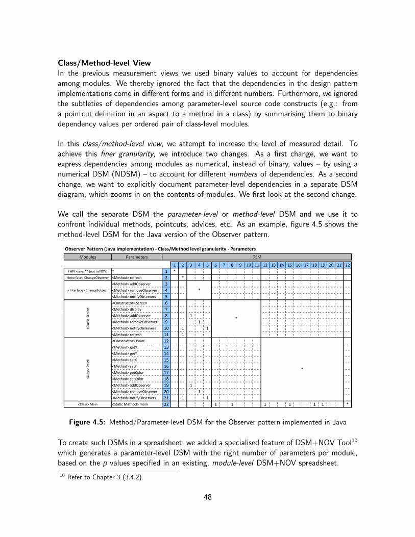
Class/Method-level ViewIn the previous measurement views we used binary values to account for dependenciesamong modules. We thereby ignored the fact that the dependencies in the design patternimplementations come in different forms and in different numbers. Furthermore, we ignoredthe subtleties of dependencies among parameter-level source code constructs (e.g.: froma pointcut definition in an aspect to a method in a class) by summarising them to binarydependency values per ordered pair of class-level modules.
In this class/method-level view, we attempt to increase the level of measured detail. Toachieve this finer granularity, we introduce two changes. As a first change, we want toexpress dependencies among modules as numerical, instead of binary, values – by using anumerical DSM (NDSM) – to account for different numbers of dependencies. As a secondchange, we want to explicitly document parameter-level dependencies in a separate DSMdiagram, which zooms in on the contents of modules. We first look at the second change.
We call the separate DSM the parameter-level or method-level DSM and we use it toconfront individual methods, pointcuts, advices, etc. As an example, figure 4.5 shows themethod-level DSM for the Java version of the Observer pattern.
e
Observer Pattern (Java implementation) ど Class/Method level granularity ど Parameters
Modules Parameters DSM
1 2 3 4 5 6 7 8 9 10 11 12 13 14 15 16 17 18 19 20 21 22
<API> java.** (not in NOV) * 1 *
<Interface> ChangeObserver <Method> refresh 2 *
<Interface> ChangeSubject
<Method> addObserver 3
<Method> removeObserver 4 *
<Method> notifyObservers 5
een
<Class>
Scr
<Constructor> Screen 6
1
*
<Method> display 7
<Method> addObserver 8 1
<Method> removeObserver 9 1
<Method> notifyObservers 10 1
<Method> refresh 11 1
<Class>
Point
<Constructor> Point 12
*
<Method> getX 13
<Method> getY 14
<Method> setX 15
<Method> setY 16
<Method> getColor 17
<Method> setColor 18
<Method> addObserver 19 1
<Method> removeObserver 20 1
<Method> notifyObservers 21 1 1
<Class> Main <Static Method> main 22 1 1 1 1 1 1 *
Figure 4.5: Method/Parameter-level DSM for the Observer pattern implemented in Java
To create such DSMs in a spreadsheet, we added a specialised feature of DSM+NOV Tool10
which generates a parameter-level DSM with the right number of parameters per module,based on the p values specified in an existing, module-level DSM+NOV spreadsheet.
10 Refer to Chapter 3 (3.4.2).
48

As far as the DSM are concerned, this clearly allows us to study dependencies in more detail.However, because the NOV model is only designed to work at the module-level we cannotcalculate NOV scores based on parameter-level DSMs. Therefore we let DSM+NOV Toollink the parameter-level DSM to the original module-level DSM by summarising throughsumming. This means that the dependency between an ordered pair of modules, as doc-umented in the module-level DSM, is now being calculated by summing the dependenciesbetween the parameters of those modules, increased with any module-level dependenciesthat were already filled out in the module-level DSM11.
This way the NOV calculation stays at the module-level, while still taking into accountinformation from the parameter-level DSM. The result for the Java version of the Observerpattern is shown in figure 4.6.
NOV Results
45max nov
Observer Pattern (Java implementation) ど Class/Method level granularity ど Modules
Modules DSM NOV Analysis
NOV Parameters Simulation of 45 Experiments
5 6ゝ Z p c n
k т 0 2 4 11
1 2 3 4 Q(k) т 0.00000 0.68100 1.04580 1.58650 2.20770
<API> java.** (not in NOV) 1 * 1
<Interface> ChangeObserver 2 * 1 2.5 0.861905 1 0.1 0.047619048 ど0.8619 ど0.4999 ど0.3104 ど0.0488 0.12821 0.12820861 0.128209
<Interface> ChangeSubject 3 1 * 2.5 1.947619 3 0.3 0.142857143 ど1.9476 ど1.3898 ど1.1309 ど0.9199 ど1.7901 ど0.919946 0.000000
<Class> Screen 4 1 2 3 * 2.5 0.009524 6 0.6 0.285714286 ど0.0095 0.55764 0.70227 0.22481 ど4.7736 0.70227094 0.702271
<Class> Point 5 1 1 3 * 2.5 0.019048 10 1 0.476190476 ど0.019 0.20341 ど0.1196 ど2.5202 ど17.639 0.20340804 0.203408
<Class> Main 6 1 2 4 * 2.5 0 1 0.1 0.047619048 0 0.36199 0.55148 0.81313 0.99011 0.99011338 0.990113
N т 21 т 1п NOV т 2.024001
Figure 4.6: Class/Method-level measurement view for the Java version of the Observerpattern: Class/Module-level DSM (+NOV calculation) linked to the method/parameter-level
DSM in figure 4.5 through summarising by summing
The beauty of this solution is that it also implements the first change we wanted to introduce.By linking both DSMs by summing parameter-level dependencies, the module-level DSMnow becomes an NDSM which literally counts the number of dependencies (e.g.: 20 callsfrom methods of class A to methods of class B result in a dependency of 20 from A to B).However, we should note this measurement view still does not differentiate between formsof dependencies (e.g.: a method calls still have the same“weight”, namely 1, as inheritancerelations).
We expected that the Class/Method-level view would have a substantial effect on NOVoutcomes. For instance, we thought this would view would penalise the fragile enumerationpointcuts in the AspectJ implementation of the pattern. But the results for the Observerpattern contradict this: the AspectJ version still scores 95% better than the Java version,as shown by figure 4.7 on the next page. Compared to the previous measurement view theNOV of the AspectJ version decreases by 7%, while the score of the Java version increasesby 7%.
11 To account for strict module-level/class-level dependencies such as inheritance, see Chapter 3 (3.4.2).
49

43
4max nov
NOV Results
1 2 3 4 5 6 7 8 т 0 0 1 1 2
Observer Pattern (AspectJ implementation) ど Class/Method level granularity ど Modules
Modules DSM NOV Analysis
NOV Parameters Simulation of 43 Experiments
6 7 8ゝ Z p c n
k т 0 3 7 18
1 2 3 5 Q(k) тQ(k) 0 00000.00000 0 88810 1 35340 1 82000 2 18970.88810 .35340 .82000 .18970
<API> java.** (not in NOV) 1 * 1
<Class> Screen 2 * 2.5 0.27083 2 0.25 0.0667 ど0.2708 0.25243 0.48612 0.60397 0.42595 0.603971615 0.603972
<Class> Point 3 1 * 2.5 0.2125 7 0.875 0.2333 ど0.2125 0.24748 ど0.0073 ど1.6896 ど6.3474 0.247482641 0.247483
<Class> Main 4 1 1 3 * 1 1 1 2.5 0 1 0.125 0.0333 0 0.39286 0.58857 0.75571 0.82029 0.82029007 0.820290
<Aspect> ObserverProtocol 5 1 * 2.5 1.4 8 1 0.2667 ど1.4 ど1.0535 ど1.5194 ど3.8504 ど10.04 ど1.05346783 0.000000
<Aspect> ColorObserver 6 1 1 1 7 * 2.5 0.00417 4 0.5 0.1333 ど0.0042 0.60655 0.76465 0.45726 ど0.8719 0.764646182 0.764646
<Aspect> CoordinateObserver 7 1 2 7 * 2.5 0.00417 4 0.5 0.1333 ど0.0042 0.60655 0.76465 0.45726 ど0.8719 0.764646182 0.764646
<Aspect> ScreenObserver 8 2 7 * 2.5 0.00417 4 0.5 0.1333 ど0.0042 0.60655 0.76465 0.45726 ど0.8719 0.764646182 0.764646
N т т 130 п NOV т 3.965683
+95.93%
Figure 4.7: Class/Method-level measurement view for the AspectJ version of the Observerpattern: Class/Module-level DSM (+NOV calculation)
SummaryFigure 4.8 summarises our findings for the Observer pattern, it lists the three experiments– based on the three measurement views – we discussed above and a fourth experiment wediscuss below.
0 0.5 1 1.5 2 2.5 3 3.5 4 4.5
Class/Method-Level(no normalisation)
Class/Method-Level
Class-Level p-counted
Naive Class-Level
NOV
Observer Design Pattern — NOV Analysis Summary
Java
AspectJ
Figure 4.8: NOV measurement results for the Observer pattern
4.5.3 Provisional Conclusions
Considering the results of the last two experiments on the Observer pattern implementations,it is clear that significantly higher dependency values only have a minor decreasing effecton NOV scores. Before we discuss experiments on other design patterns this observationrequires further investigation.
Even when dependency values for a module are doubled or even tripled NOV scores are onlyslightly affected and sometimes not affected at all. Our first suspicion was that this couldbe due to the fact that our implementation of the NOV model normalises the negative novi
50
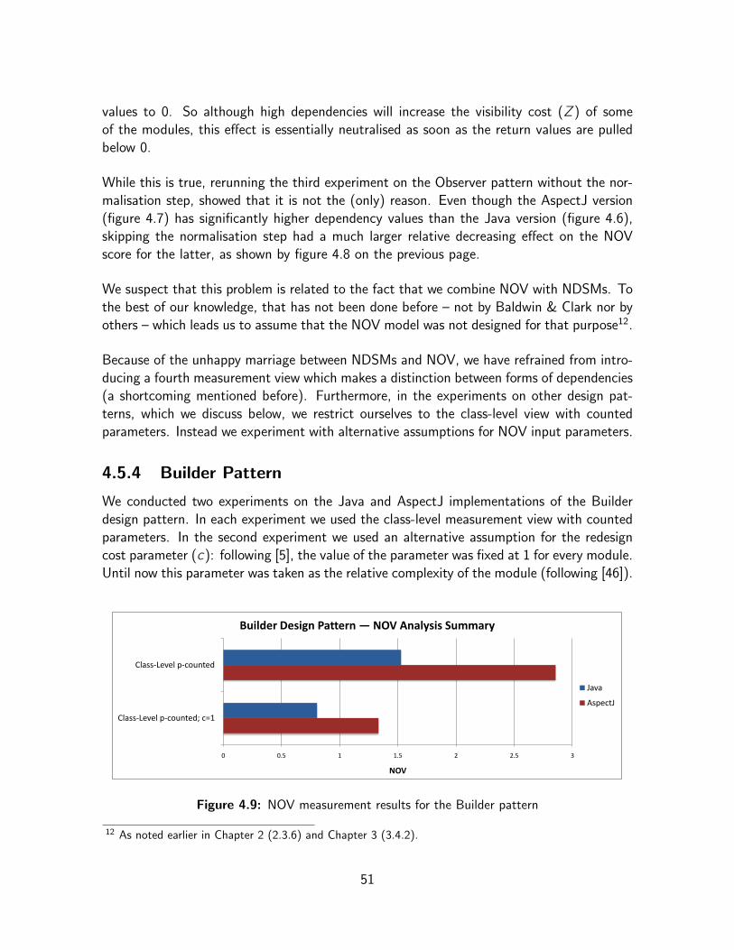
values to 0. So although high dependencies will increase the visibility cost (Z) of someof the modules, this effect is essentially neutralised as soon as the return values are pulledbelow 0.
While this is true, rerunning the third experiment on the Observer pattern without the nor-malisation step, showed that it is not the (only) reason. Even though the AspectJ version(figure 4.7) has significantly higher dependency values than the Java version (figure 4.6),skipping the normalisation step had a much larger relative decreasing effect on the NOVscore for the latter, as shown by figure 4.8 on the previous page.
We suspect that this problem is related to the fact that we combine NOV with NDSMs. Tothe best of our knowledge, that has not been done before – not by Baldwin & Clark nor byothers – which leads us to assume that the NOV model was not designed for that purpose12.
Because of the unhappy marriage between NDSMs and NOV, we have refrained from intro-ducing a fourth measurement view which makes a distinction between forms of dependencies(a shortcoming mentioned before). Furthermore, in the experiments on other design pat-terns, which we discuss below, we restrict ourselves to the class-level view with countedparameters. Instead we experiment with alternative assumptions for NOV input parameters.
4.5.4 Builder Pattern
We conducted two experiments on the Java and AspectJ implementations of the Builderdesign pattern. In each experiment we used the class-level measurement view with countedparameters. In the second experiment we used an alternative assumption for the redesigncost parameter (c): following [5], the value of the parameter was fixed at 1 for every module.Until now this parameter was taken as the relative complexity of the module (following [46]).
0 0.5 1 1.5 2 2.5 3
Class-Level p-counted; c=1
Class-Level p-counted
NOV
Builder Design Pattern — NOV Analysis Summary
Java
AspectJ
Figure 4.9: NOV measurement results for the Builder pattern
12 As noted earlier in Chapter 2 (2.3.6) and Chapter 3 (3.4.2).
51

Figure 4.9, on the previous page, summarises the results for both experiments. Again,the AspectJ implementation scores much higher than the Java equivalent. The effect ofthe alternative assumption for the redesign cost is a decrease in NOV for both versions.Although the AspectJ score is relatively more affected, it remains 65% above the score ofthe Java version.
4.5.5 Composite Pattern
Our final two DSM+NOV experiments were carried out on the Java and AspectJ imple-mentations of the Composite design pattern. In both experiments we used the class-levelmeasurement view with counted parameters. In the second experiment we introduce a novelassumption for the complexity parameter (n).
Until now, the complexity of a module was proportional to the number of design parametersthe module contains (following [5]). Because we consider the number of methods, construc-tors, pointcuts, advices, etc. to be a rather inaccurate estimate of the actual size of classes,interfaces or aspects, let alone of their complexity, we try out an alternative approach. Wepropose to take the complexity of a module as the proportional amount of lines of code(LoC) contributed by the source code entity the module represents, relative to the totalnumber of lines of the studied software system. Formally the complexity of the i -th moduleis computed as ni =
LoC i∑j
LoCj.
NOV Results
54max nov
Composite Pattern (AspectJ implementation) ど Class level granularity with counted parameters (p)
Modules DSM NOV Analysis
NOV Pa Simulation of rameters 54 Experiments
4 5 6ゝ Z p c n
k т 0 2 3 13 22
1 2 3 Q(k) т 0.0000 0.6810 0.8881 1.6680 1.9097 2.2789
<API> java.** (not in NOV) 1 * 1
<Aspect> CompositeProtocol 2 1 * 2.5 0.2832 11 1 0.4231 ど0.2832 ど0.0219 ど0.1082 ど3.0709 ど6.4855 ど19.424 ど0.02193 0.000000
<Class> Directory 3 * 2.5 0.2867 2 0.1818 0.0769 ど0.2867 0.15753 0.28715 0.68802 0.72973 0.53818 0.72973 0.729728
<Class> File 4 * 2.5 0.2867 3 0.2727 0.1154 ど0.2867 0.22869 0.3731 0.72068 0.6427 ど0.0507 0.72068 0.720675
<Aspect> FileSystemComposition 5 1 1 1 1 * 2.5 0.0035 9 0.8182 0.3462 ど0.0035 0.43179 0.4532 ど1.2319 ど3.4254 ど11.945 0.4532 0.453203
<Class> Main 6 1 1 1 1 * 2.5 0 1 0.0909 0.0385 0 0.32691 0.42496 0.77235 0.85938 0.92852 0.92852 0.928518
N т 26 п т 1 NOV т 2.832124
(a)
NOV Results
18novmax
Composite Pattern (AspectJ implementation) ど Class level granularity with counted parameters (p)
Modules DSM NOV Analysis
NOV Parameters Simulation of 18 Experiments
4 5 6ゝ Z c LoC n
k т 0 2 3 5 12
1 2 3 Q(k) т 0.0000 0.6810 0.8881 1.1697 1.6293 1.8200
<API> java.** (not in NOV) 1 *
<Aspect> CompositeProtocol 2 1 * 2.5 0.2376 1 188 0.3281 ど0.2376 0.0814 0.04989 ど0.2031 ど1.8417 ど3.5371 0.0814 0.081402
<Class> Directory 3 * 2.5 0.3736 0.234 44 0.0768 ど0.3736 0.0623 0.18781 0.34692 0.53948 0.56381 0.56381 0.563814
<Class> File 4 * 2.5 0.3736 0.3191 60 0.1047 ど0.3736 0.11055 0.24468 0.40562 0.54345 0.49728 0.54345 0.543452
<Aspect> FileSystemComposition 5 1 1 1 1 * 2.5 0.1359 0.8511 160 0.2792 ど0.1359 0.28849 0.32445 0.22112 ど0.8353 ど2.0091 0.32445 0.324451
<Class> Main 6 1 1 1 1 * 2.5 0 0.6436 121 0.2112 0 0.51057 0.61259 0.66423 0.24079 ど0.3555 0.66423 0.664230
пт573 п т 1 NOV т 2.177349
(b)
Figure 4.10: Class-level view with counted parameters for the Composite pattern inAspectJ; using the conventional (a) and a LoC-based (b) assumption for module complexity
52

Figure 4.10, on the previous page, shows DSM+NOV spreadsheets for the AspectJ versionof the Composite design pattern, using the conventional (a) and the new (b) assumptionfor the complexity parameter.
0 0.5 1 1.5 2 2.5 3
Class-Level p-counted;LoC-based complexity
Class-Level p-counted
NOV
Composite Design Pattern — NOV Analysis Summary
Java
AspectJ
Figure 4.11: NOV measurement results for the Composite pattern
Figure 4.11 summarises the results for the Composite pattern experiments. The AspectJversion of the pattern scores higher in both experiments. The effect of the LoC-basedcomplexity is remarkable. The new assumption results in a decrease in NOV for bothversions, but the relative (and absolute) difference is much larger for the Java version incomparison with AspectJ version.
4.5.6 Conclusions
4.5.6.1 Summary
We observed that experimenting with different measurement approaches – or views as wecall them – and alternative NOV parameter assumptions, had an influence on the measuredNOV scores but never significantly affected the dominance of the AspectJ versions over theJava versions of the studied design patterns.
However, we should stress that, due to a number of issues regarding the applicability of theNOV model as a software metric (see below), the results of our experiments cannot be usedto draw conclusions on the claimed modularity advantages of the aspect-oriented designpattern implementations, over the object-oriented implementations.
4.5.6.2 Evaluating the Applicability of the NOV Model
Based on the experiments and findings discussed above we now present our conclusions withregard to the applicability of NOV model as a modularity metric for software design.
53

As already noted in Chapter 2, the NOV model is not a black box. Its application for aparticular purpose requires a multitude of assumptions, appropriate for the given context,about the input parameters of the model. This requires a thorough understanding of themeaning of those parameters.
To explore the possibilities of the DSM+NOV methodology, we experimented with alterna-tive measurement approaches and assumptions for the input parameters of the NOV model.However, we were unable to find an optimal approach.
Our experiment with the LoC-based assumption for the complexity parameter is an illus-trative example. Even though all other parameters were kept constant, the results show astriking discrepancy between the effect on the NOV score of the AspectJ version and theeffect on the result for the Java version of the Composite pattern. While we thought thatLoC-based module complexity makes sense in the context of software, we have most likelymisunderstood the true meaning of the parameter.
We consider the idea to assess modularity using a module-level and a parameter-level DSMto be a powerful concept. Moreover, we hoped this approach would reveal more about theinteractions between design pattern participants, for instance with regard to fragile point-cuts. However the results were disappointing. Due to the problematic combination of NDSMand the NOV model, significantly higher (numerical) dependency values only had a negli-gible decreasing effect on the NOV scores. We do not rule out the possibility that furtheradjustments to the input parameters of the NOV model could render it more suitable tobe combined with numerical dependency values. However, our insight into the meaning ofthese parameters in the context of software is insufficient to fine-tune the model ourselves.
We must conclude that the current level of understanding of the input parameters and theoutcome of the NOV model is limited and does not warrant the application of the model asa modularity metric for real-world software designs.
We are not alone in these observations. Other authors have expressed similar concerns, asnoted in our discussion of related work in section 4.3. In fact, all previous publications onthe application of the NOV model to software design, mention at least some reservationsabout the applicability of the model. For example, in [72] Sullivan et al. said:
“[Quantitative models] need not be perfect. However, they must capture themost important terms and their assumptions and operation must be known andunderstood so that analysts understand and can evaluate their predictions.”
In our opinion, these requirements are not met by the current state of the NOV model insoftware. Furthermore, our findings re-establish the question as to whether the model is atall applicable in this context.
54

Possibly, developing a new quantitative model based on DSMs, specifically designed to assessmodularity in software, would be a better approach for future research than further attemptsto grasp and adapt the NOV model. However, that is outside the scope of this dissertation.
4.6 Conclusions
In this chapter we have presented an evaluation the DSM+NOV methodology for quantita-tive assessment of modularity in software designs.
To experiment with the methodology, we applied it to aspect-oriented and object-orientedimplementations of the GoF design patterns, in order to assess the claimed modularisationadvantages of the former implementations. However, we first provided an extensive intro-duction to the novel aspect-orientation paradigm.
In our experiments we presented three measurement views and we conducted an initial ex-ploration of the value space of the input parameters of NOV model. The class/method-levelmeasurement view and the LoC-based assumption for the complexity parameter, which weintroduced here, constitute novel ideas in the field.
Based on our observations, we have concluded that we lack a solid rationale to supportapplication of the NOV model in the context of software development. Hence, the resultsof our assessment cannot be used to draw conclusions with regard to the modularisationproperties of the aspect-oriented and object-oriented design pattern implementations.
Despite the issues of the NOV model, our experiments suggest that DSM diagrams alone areindeed a powerful way to document and visualise dependencies in software implementations.This is confirmed by our research, which we present in the following two chapters, into tothe application of DSM visualisations in support tools for software development.
55

Chapter 5
DSM-based Code Browsers
This chapter covers our research into DSM-based support tools for object-oriented softwaredevelopment (OOSD). We argue that DSMs are well-suited to be applied to OOSD andoffer a novel approach to dependency management. We propose a rationale for an extend-able DSM-based source-code browser with analysis capabilities based on metaprogramming.Subsequently, we present a prototype of such a tool. In the next chapter we demonstratehow this prototype can assist developers in common tasks.
5.1 Introduction
In Chapter 2 we introduced the Design Structure Matrix (DSM) as a type of diagram thatfocuses on the modular structure of systems and the dependencies among their constituentparameters, parts or modules. In our opinion these characteristics make DSM diagrams auseful instrument to support object-oriented software development (OOSD). Specifically, webelieve that DSMs are suitable to visualise the hierarchical structure of software componentsand to help developers with managing the different kinds of dependencies among those1.The work we present in this chapter attempts to validate this assumption by extendingsource-code browsers with DSM capabilities.
Source-code browsers are tools that integrate with development environments to extendthem with facilities that enable easy navigation through the implementation of a pieceof software, usually by means of an abstract representation that is coupled to the actualconstructs in the source code. By keeping the representation, which is commonly based onsome kind of diagrams, in sync with the implementation at all times, both are said to co-evolve [17, 76]. In case of DSM-based code browsers, co-evolution means there is a causallink between changes in the source code and resulting shifts in the dependency patternsvisualised by a DSM diagram.
1 As explained in Chapter 4 (4.5.6.2), we think that the Net Option Value (NOV) model currently cannotbe confidently applied to study software designs, therefore we focus exclusively on DSMs in this chapter.
56

Although code browsers are metaprograms2 in their own right, exposing metaprogrammingfacilities to the user can make them significantly more powerful. Such facilities enabledevelopers to obtain diverse kinds of knowledge about a software implementation by writingsmall, ad-hoc analysis programs that reason about the source code using a framework ofabstractions provided by the tool. In a DSM-based tool such metaprograms could use theabstractions – representing modules and dependencies in the source code – that make upthe DSM, as a new reflective application programming interface (API) to reason about thesource code.
In short, the research we discuss here combines design structure matrixes, source-codebrowsers and metaprogramming. To investigate the opportunities this combination holds forOOSD, we have formulated a rationale and created a prototype of an extendable DSM-basedsource-code browser with analysis capabilities based on metaprogramming. This prototype,or future similar tools, can both passively and actively support developers in acquiringimportant information, for instance with regard to decisions concerning local architecturalrestructurings. This is demonstrated by the case studies we present in Chapter 6.
In section 5.2 of this chapter, we discuss some observations about the discipline of OOSDthat make the case for DSM-based support tools. Next, section 5.3 presents a rationalefor such a tool consisting of a set of requirements and the approach we propose in theform of a DSM-based source-code browser. After that, section 5.4 presents DSMBrowser,our prototype implementation. Finally, we discuss some related work in section 5.5 and weconclude this chapter in section 5.6.
5.2 Motivation
In this section we deal with the motivations for our research into DSM-based support tools forOOSD. First, we discuss modularisation and dependencies in object-oriented (OO) softwareand we present of an argument for a hierarchical interpretation of those phenomena. Next,we present arguments that stress the importance of dependency management in OOSD.
5.2.1 Modularity and Dependencies in Object-Oriented Software
In object-orientation, today’s de-facto software development paradigm, software is con-structed from cooperating entities called objects. Objects are data structures with behaviour– they contain data fields and units of behaviour called methods. In most object-orientedlanguages objects are instances of classes, which act as static blueprints. Objects must co-operate to perform the functions of the software. Therefore, an object can hold referencesto other objects in its data fields and its methods can access fields of other objects or invoke
2 Metaprograms are commonly defined as programs that reason about or manipulate other programs (orthemselves) as their data.
57

external methods by sending messages to other objects. Objects can also engage in otherrelationships with one another. For instance, objects can be related through inheritance.
These relationships bring about different kinds of dependencies among objects and theirmethods. Both objects (or their classes) and methods can be seen as modules – in thesense of the definitions we discussed in Chapter 2 (2.3.1) – on different hierarchical levels.
Object-orientation provides technical mechanisms that create a grouping hierarchy – in par-allel with an inheritance hierarchy – of modular abstractions. Methods represent portions ofcode as abstract units of behaviour and are at the bottom of this hierarchy. One level up wefind objects which group methods, together with data structures, into abstract modules ofdata and behaviour. Objects, for their part, can be arranged in packages, bundles, names-paces, etc. Such groups of objects do not always correspond to functional abstractions,but nevertheless these techniques provide an additional level – or multiple levels, as thesegroupings can usually be nested – in the hierarchy.
Ideally, the modularisation that is achieved using such technical mechanisms, groups con-ceptually related and separates conceptually unrelated things. In other words, the technicalmodularisation should align with a conceptual modularisation – one that makes sense withregard to the requirements for the system in question. However, such correspondence is notalways trivial to achieve.
Modularisations in software are never one-dimensional, but span multiple hierarchical lev-els. Hence, dependencies among modules can cross the boundaries of surrounding moduleson higher levels. For example, a method might invoke a method of the same object (noboundary crossed), of another object in the same package (1 boundary crossed) or of anobject in another package (2 boundaries crossed). Furthermore, dependencies can intersectwith hierarchical levels when a module depends on a module situated on a different level.For instance, in a statically typed language a method might reference a class by its name asthe type of a variable. Moreover, dependencies on a particular level cannot be ignored onhigher levels in the hierarchy. For example, inheritance between objects in different packagesintroduces a dependency among those objects but also between the involved packages.
In summary, both modularity and dependency in object-oriented software should be treatedas hierarchical phenomena.
5.2.2 Dependency Management
While object-oriented modularisation has its limitations3, it simplifies the design of modulararchitectures compared to older paradigms. Such architectures facilitate the cooperation of
3 In Chapter 4 we discuss Aspect-Oriented Software Development (AOSD), a new paradigm that is in-tended to resolve important limitations of object-oriented modularisation.
58

large groups of developers and can thus increase the scalability of software development.However, a modular architecture does not mean that dependencies among software com-ponents can be ignored. In fact, there are several arguments that stress the importance oftrue dependency management for OOSD.
Coordination effortsThe implementation of a large software system is rarely the work of one person or a smallteam, but usually requires the cooperation of large groups of people with diverse specialisa-tions and responsibilities.
Whenever multiple developers cooperate, implementation-level dependencies translate todependencies among individuals and groups of people. For example, when implementationcomponents that depend on each other are the responsibility of different people, certaincoordination efforts are essential to guarantee their proper functioning. Such coordinationtakes many forms, ranging from verbal agreements among individual programmers to moreadvanced methods. The cost related to coordination efforts in large-scale projects can besignificant [40].
Existing and Third-party CodeThe source code that makes up large software implementations is unlikely to be entirelywritten from scratch. Existing or third-party written code is used in virtually all softwaredevelopment projects, even for new applications that do not extend or improve on an earlierversion. This code takes very diverse forms – libraries, frameworks, middleware components,etc. and recycled code in general – and originates from several sources both in- and outsidea company – it may be written in-house by the same team or by another team, developmentmay be out-sourced to employees of a consultancy firm (on-site or elsewhere, possibly evenabroad) or it can be bought as a product from another company.
Existing and third-party written code further complicate dependencies in software imple-mentations and thus affect the corresponding dependencies among people as well.
The use of existing code extends dependencies among people over time. For instance, whenold, “legacy” code is used, crucial knowledge might have been lost because the responsibledevelopers may have left the company. This hinders the maintenance and evolution of thesoftware system. In some cases, reengineering or even entirely replacing legacy components,is the only solution. However, such steps cannot be taken overnight, especially in missioncritical applications. They require a meticulous planning and a design which takes all de-pendencies, from components that are to stay to the legacy components, into account.
The use of third-party written code extends the range of involved parties – from individualdevelopers and teams to departments and even whole companies – and therefore it both
59
increases the number and widens the scope of dependencies among people. This can be asource of problems, for instance when the involved parties do not share the same interests.This is especially the case when dependencies involve products from different companies –each protecting its own investments and market shares. A consequence is that companiesusually do not have the same amount of control over code that is supplied by other firmsthan over what is developed in-house. For example, it may be unavoidable that a new versionof a third-party framework introduces changes that are incompatible with some applicationsthat depend on it. In that sense, third-party code can be a moving target.
The Importance of Dependency ManagementIn summary, it is of vital importance that developers know well what their code relies onand how and why it does so. This emphasises the importance of dependency managementfor (object-oriented) software development. Sound dependency management supports co-ordination and communication among involved parties. It requires that efforts are madeto know and to keep track of dependencies, throughout the lifecycle of a software product.Moreover, it means that opportunities for improved modularisation – resulting in dependencyminimisations – are detected, evaluated and pursued at various development stages.
5.3 Rationale
In this section we present a rationale for a novel support tool for OOSD based on DSMs.We first list a number of requirements which follow from the motivations discussed above.Next, we propose an approach in the form of an extendable DSM-based source-code browserwith analysis capabilities based on metaprogramming.
5.3.1 Requirements
The central goal is to devise a tool that supports dependency management and integrateswell with the day-to-day practice of object-oriented software development. We infer fiverequirements for such a tool from the motivations we discussed earlier:
Requirement 1 It is of key importance to offer a visual overview of the dependenciesamong different modules in a software implementation. The visualisation should enableusers to study modularisations, for instance to verify whether technical modularisationsmap to conceptual ones and whether design choices are upheld. The tool should distinguishdifferent dependency kinds on different hierarchical levels. In other words, it should explicitlydeal with the hierarchical nature of both modularity and dependencies in OO software.
Requirement 2 Furthermore, the tool should be flexible enough to enable developers tofocus on the regions and hierarchical levels of their choice, instead of burying them with toomuch information in an overloaded visualisation.
60
Requirement 3 The provided visualisation should not be static, on the contrary it shouldat least support interactive navigation, both laterally and hierarchically. Additionally, visu-alisation elements on every level should be linked to the underlying source code constructs,allowing users to move back and forth between the visualisation and the source code.
Requirement 4 The tool should help developers to find and evaluate modularisationopportunities in the form of local architectural restructurings. We do not seek an instrumentthat autonomously introduces such restructurings, nor a general-purpose expert system.Rather, the tool should offer a set of customisable, manually-triggered analysis featuresthat provide information and indicative suggestions – with regard to the minimisation ofdependencies through object-oriented modularisations – that support, rather than replace,human decisions.
Requirement 5 Finally, the tool should be extendable so that users can customise it forspecific applications and for deployment in specific environments.
5.3.2 Approach
The solution we propose to satisfy the requirements listed above is an extendable DSM-based source-code browser with analysis capabilities based on metaprogramming. We nowdiscuss the prominent aspects of this approach.
5.3.2.1 DSM-based Visualisation
We believe that DSMs, through their focus on modular structures and dependencies, offera suitable basis for the visualisation described by requirements 1 and 2.
While some modules in object-orientation, such as objects or methods, are apparent asexplicit units of code, this is not always true for others, such as packages or namespaces.Most dependencies in object-orientation are explicitly defined, but often by individual linesof code (e.g.: a method call or the specification of inheritance relations in a class header),which makes them hard to track down. However, a DSM-based visualisation can display allmodules in the same, explicit, way and can offer a convenient overview of all dependencies,no matter where or how they are defined.
We suggest to differentiate types of dependencies by labelling them with different“weights”.Additionally, the DSMs should accurately represent the number of dependencies betweenmodules. Therefore we propose to use NDSMs4, instead of regular, binary, DSMs. In theremainder of this chapter we will use the term “DSM” to refer to NDSMs.
4 NDSMS are DSMs with numerical, instead of binary, dependency values, see Chapter 2 (2.2). Unlike inChapter 4 (4.5.3), their use can not pose a problem here as they are not combined with NOV analysis.
61

To comply with requirement 1 the visualisation should explicitly deal with the hierarchicalnature of modularity and dependencies in object-orientation. However, a single, standardDSM diagram is too limited for that. Therefore we look at two extended DSM-based visu-alisation concepts. First, we consider the possibility of using a linked series of DSMs, whereeach DSM represents a single hierarchical level. While this would be a major improvementover a standard DSM diagram, it still does not fully satisfy requirement 1. Because of that,we propose a second visualisation approach which combines multiple hierarchical levels intoa single tree-based DSM diagram. The second approach fully complies to requirement 1and we have implemented it in our prototype.
Linked Series of DSMsThe concept of a linked series of DSMs builds further upon a concept we introduced inChapter 3 (3.4.2) in connection with our spreadsheet generation tool. There, the idea wasto use a couple of two DSMs, a “module-level” one and a “parameter-level” one, to simul-taneously document dependencies on two hierarchical levels. Both diagrams could then belinked by letting the module-level DSM summarise the dependency values of the parameter-level DSM, either by summing or maximising them, per ordered pair of modules.
Here, we propose to extend this couple of DSMs to an unlimited series of DSMs, eachrepresenting a different hierarchical level of the studied system5. The DSMs in the seriesshould be linked by summarising lower level dependencies through summing6.
Equation 5.1 formally defines how the DSMs in such a hierarchical series are to be linked.We number the DSMs in the series so that the one that corresponds to the lowest hierar-chical level is labelled with the number 1, and those representing higher levels are labelledwith increasing numbers. Then, a dependency value from DSMH accounts for all directdependencies – those occurring strictly on the H-th level – between an ordered pair ofmodules situated on the H-th hierarchical level, and unless H = 1, also for all lower-leveldependencies – which are summarised from DSM(H−1) by summing – between submodulesof the ordered pair.
dHi,j =
DHi,j +
∑∀p ∈ i , ∀q ∈ j
d(H−1)p,q for H > 1
DHi,j for H = 1
(5.1)
In the equation:
• dXa,b is a dependency value (from DSMX), which represents the dependencies from amodule a to another module b, both situated on the X-th level in the hierarchy;
5 We hereby slightly alter the meaning, as defined in Chapter 3 (3.4.2), of modules containing (design)parameters, because modules now contain other modules as their parameters (or submodules).
6 Summarising by maximising makes no sense here because we do not want to ignore any lower leveldependencies on higher hierarchical levels.
62
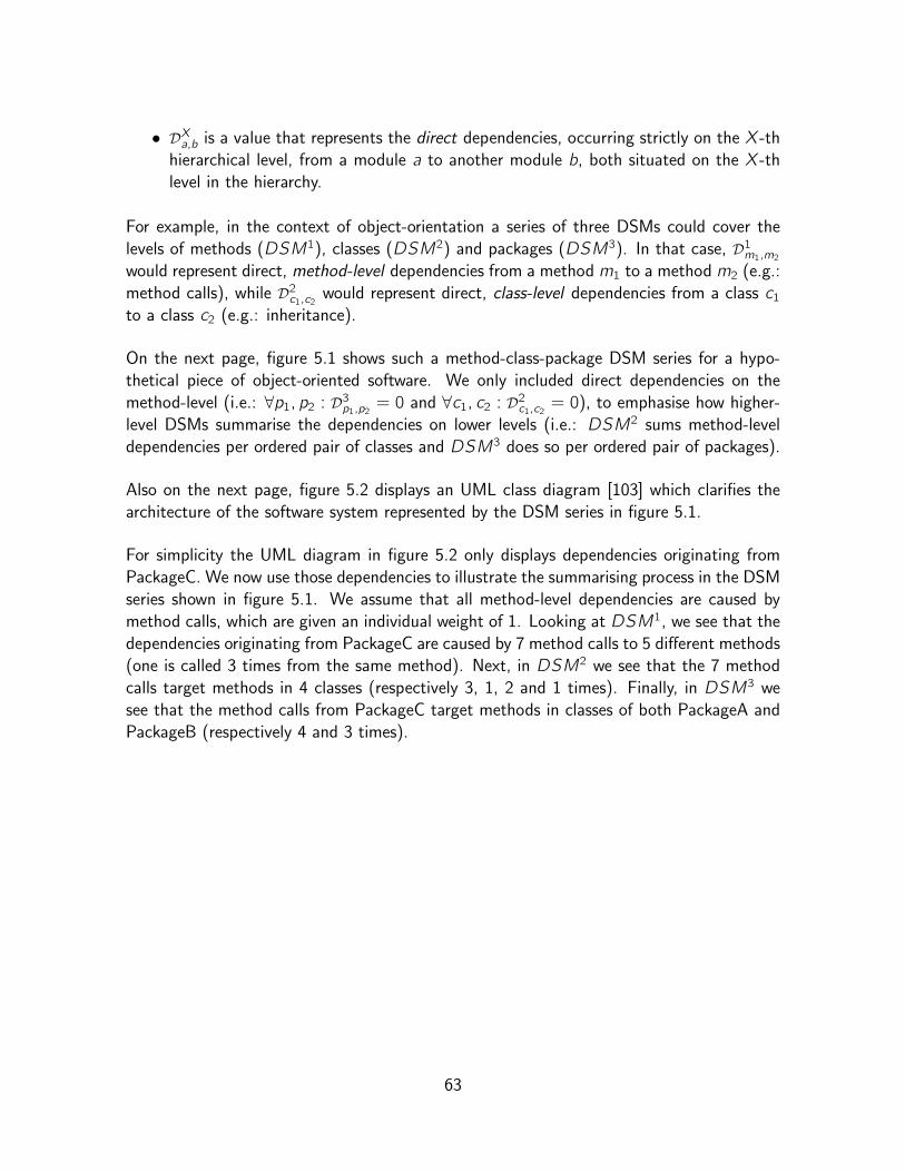
• DXa,b is a value that represents the direct dependencies, occurring strictly on the X-thhierarchical level, from a module a to another module b, both situated on the X-thlevel in the hierarchy.
For example, in the context of object-orientation a series of three DSMs could cover thelevels of methods (DSM1), classes (DSM2) and packages (DSM3). In that case, D1m1,m2would represent direct, method-level dependencies from a method m1 to a method m2 (e.g.:method calls), while D2c1,c2 would represent direct, class-level dependencies from a class c1to a class c2 (e.g.: inheritance).
On the next page, figure 5.1 shows such a method-class-package DSM series for a hypo-thetical piece of object-oriented software. We only included direct dependencies on themethod-level (i.e.: ∀p1, p2 : D3p1,p2 = 0 and ∀c1, c2 : D2c1,c2 = 0), to emphasise how higher-level DSMs summarise the dependencies on lower levels (i.e.: DSM2 sums method-leveldependencies per ordered pair of classes and DSM3 does so per ordered pair of packages).
Also on the next page, figure 5.2 displays an UML class diagram [103] which clarifies thearchitecture of the software system represented by the DSM series in figure 5.1.
For simplicity the UML diagram in figure 5.2 only displays dependencies originating fromPackageC. We now use those dependencies to illustrate the summarising process in the DSMseries shown in figure 5.1. We assume that all method-level dependencies are caused bymethod calls, which are given an individual weight of 1. Looking at DSM1, we see that thedependencies originating from PackageC are caused by 7 method calls to 5 different methods(one is called 3 times from the same method). Next, in DSM2 we see that the 7 methodcalls target methods in 4 classes (respectively 3, 1, 2 and 1 times). Finally, in DSM3 wesee that the method calls from PackageC target methods in classes of both PackageA andPackageB (respectively 4 and 3 times).
63
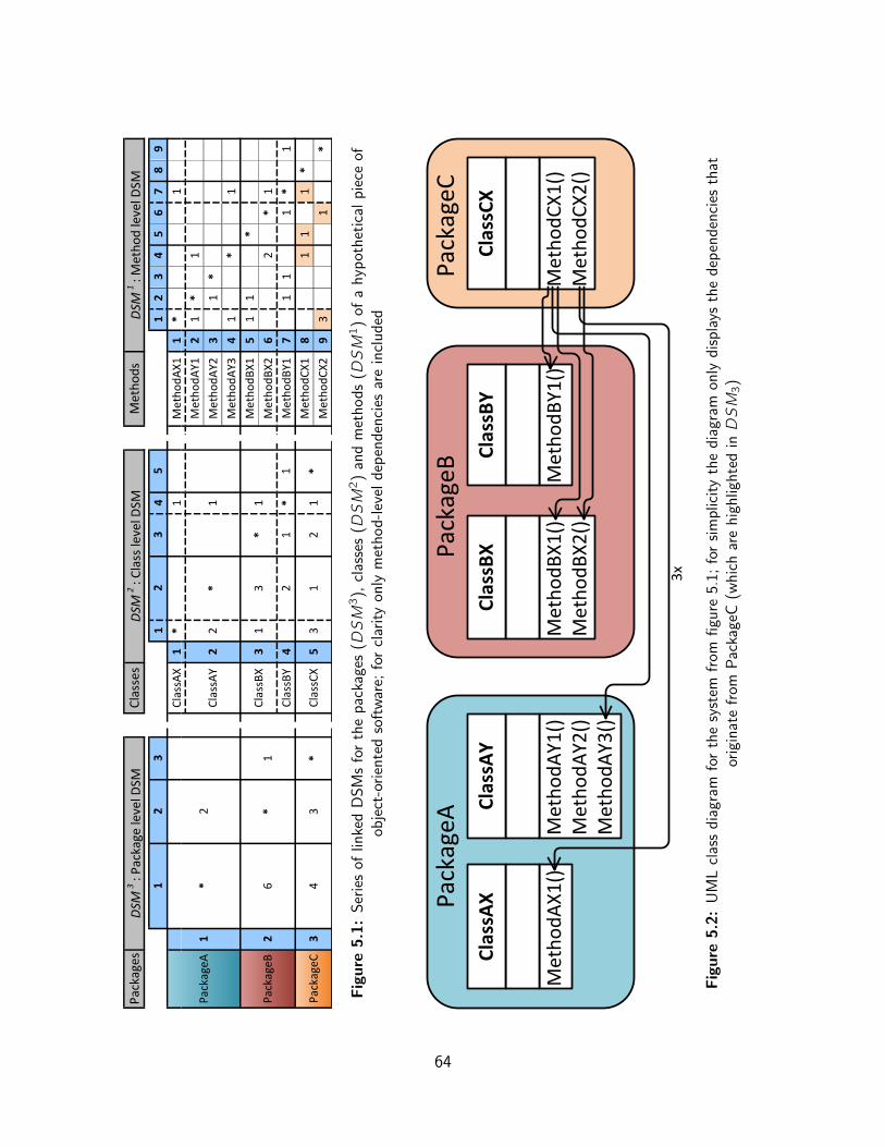
: Method
level D
SM
Packages
DSM
3: Package
level D
SM
Classes
DSM
2: C
lass
level D
SM
Methods
DSM
1
12
31
24
53
12
34
56
78
9
PackageA
1*
2
ClassAX
1*
1M
X1
ethodA
1*
1
Class
22
AY
*
MethodAY1
21
*1
1MethodAY2
31
*
MethodAY3
41
*1
PackageB
26
*1
Class
31
BX
3*
1MethodBX1
51
1*
MethodBX2
62
*1
ClassBY
42
*1
1Meth
1odBY
71
11
*1
PackageC
34
3*
Class
35
CX
12
1*
MethodCX1
81
11
*
Meth
X2
odC
93
1*
Fig
ure
5.1
:S
erie
sof
linke
dD
SM
sfo
rth
ep
acka
ges
(DSM3),
clas
ses
(DSM2)
and
met
ho
ds
(DSM1)
ofa
hyp
oth
etic
alp
iece
ofob
ject
-ori
ente
dso
ftw
are;
for
clar
ity
only
met
ho
d-l
evel
dep
end
enci
esar
ein
clu
ded
PackageA
MethodAX1()
ClassAX
MethodAY1()
MethodAY2()
MethodAY3()
ClassAY
PackageC
MethodCX1()
MethodCX2()
ClassCX
PackageB
MethodBY1()
ClassBY
MethodBX1()
MethodBX2()
ClassBX
3x
Fig
ure
5.2
:U
ML
clas
sd
iagr
amfo
rth
esy
stem
from
figu
re5.
1;fo
rsi
mp
licit
yth
ed
iagr
amon
lyd
isp
lays
the
dep
end
enci
esth
ator
igin
ate
from
Pac
kage
C(w
hic
har
eh
igh
ligh
ted
inDSM3)
64
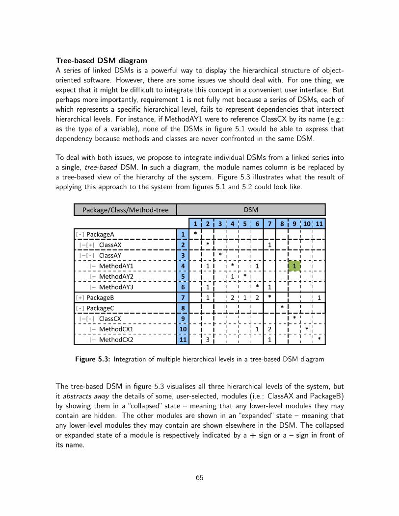
Tree-based DSM diagramA series of linked DSMs is a powerful way to display the hierarchical structure of object-oriented software. However, there are some issues we should deal with. For one thing, weexpect that it might be difficult to integrate this concept in a convenient user interface. Butperhaps more importantly, requirement 1 is not fully met because a series of DSMs, each ofwhich represents a specific hierarchical level, fails to represent dependencies that intersecthierarchical levels. For instance, if MethodAY1 were to reference ClassCX by its name (e.g.:as the type of a variable), none of the DSMs in figure 5.1 would be able to express thatdependency because methods and classes are never confronted in the same DSM.
To deal with both issues, we propose to integrate individual DSMs from a linked series intoa single, tree-based DSM. In such a diagram, the module names column is be replaced bya tree-based view of the hierarchy of the system. Figure 5.3 illustrates what the result ofapplying this approach to the system from figures 5.1 and 5.2 could look like.
Package/Class/MethodͲtree DSM
1 2 3 4 5 6 7 8 9 10 11
[-] PackageA 1 *
|—[+] ClassAX 2 * 1
|—[-] ClassAY 3 *
|— MethodAY1 4 1 * 1 1
|— MethodAY2 5 1 *
|— MethodAY3 6 1 * 1
[+] PackageB 7 1 2 1 2 * 1
[-] PackageC 8 *
|—[-] ClassCX 9 *
|— MethodCX1 10 1 2 *
|— MethodCX2 11 3 1 *
Figure 5.3: Integration of multiple hierarchical levels in a tree-based DSM diagram
The tree-based DSM in figure 5.3 visualises all three hierarchical levels of the system, butit abstracts away the details of some, user-selected, modules (i.e.: ClassAX and PackageB)by showing them in a “collapsed” state – meaning that any lower-level modules they maycontain are hidden. The other modules are shown in an “expanded” state – meaning thatany lower-level modules they may contain are shown elsewhere in the DSM. The collapsedor expanded state of a module is respectively indicated by a + sign or a – sign in front ofits name.
65

This approach does support representing dependencies which intersect hierarchical levels –as demonstrated by the highlighted dependency from MethodAY1 to ClassCX in the diagramin figure 5.3 – and thus fully complies with requirement 1.
Furthermore, a tree-based DSM diagram is ideal to be integrated in an interactive graphicaluser interface (GUI). The idea is to dynamically repaint the displayed DSM diagram whena user collapses of expands a module in an on-screen hierarchy tree.
Collapsing and expanding modules is respectively equivalent to zooming in and out on thevisualisation and allows us to meet requirements 2 and 3. It facilitates hierarchical navigationthrough the system – for instance, by recursively expanding modules we can “drill down” tothe source of a particular dependency. Lateral navigation can be achieved by selectivelycollapsing and/or expanding modules – for example, by collapsing those modules we donot and expanding those do care about, we can focus on what is important at a particularmoment and avoid overloaded visualisations.
We should note that the choice to visualise software structures using tree-based DSMswas partially inspired by Lattix LDM, one of the applications we discuss as related work insection 5.5.
In summary, the tree-based DSM diagram resolves the issues of the linked series of DSMsand is therefore the preferred visualisation approach. Consequently, this is what we haveimplemented in the prototype we discuss in section 5.4.
To conclude, we present a formal definition, by means of equations 5.2, 5.3 and 5.4, of thedependency values in a tree-based DSM.
ti ,j = Di ,j + hi ,j (5.2)
hi ,j =
∑∀p ∈ i
sp,j +∑∀q ∈ j
si ,q +∑
∀p ∈ i , ∀q ∈ j
sp,q when i and j are in collapsed state
∑∀p ∈ i
sp,j when only i is in collapsed state
∑∀q ∈ j
si ,q when only j is in collapsed state
0 when i nor j is in collapsed state(5.3)
66

sx,y = Dx,y +
∑∀a ∈ x
sa,y +∑∀b ∈ y
sx,b +∑
∀a ∈ x, ∀b ∈ y
sa,b when x 6= ∅ and y 6= ∅
∑∀a ∈ x
sa,y when x 6= ∅ and y = ∅
∑∀b ∈ y
sx,b when x = ∅ and y 6= ∅
0 when x = ∅ and y = ∅(5.4)
In the equations:
• ti ,j is a dependency value between a module i and another module j as it is displayedin a tree-based DSM; where i and j can be situated on different hierarchical levels ofthe represented system;
• hi ,j represents the portion of ti ,j that accounts for dependencies to and/or from mod-ules which are hidden because of the collapsedness of i , j or both:
– if both i and j are collapsed hi ,j is taken as the recursive sum of the dependenciesfrom all submodules of i to j , those from i to all submodules of j and those fromall submodules of i to all submodules of j ,
– if only i is collapsed hi ,j is taken as the recursive sum of the dependencies fromall submodules of i to j ,
– if only j is collapsed hi ,j is taken as the recursive sum of the dependencies fromi to all submodules of j ,
– if i nor j is collapsed then all their submodules are visible elsewhere in the DSM,so hi ,j = 0;
• The value Dx,y represents all direct dependencies from a module x to a module y (andnot from/to their submodules); where x and y can be situated on different hierarchicallevels;
• sx,y recursively sums all dependencies from a module x , and its submodules, to anothermodule y , and its submodules; where x and y can be situated on different hierarchicallevels.
Furthermore:
• A module m, situated at a H-th hierarchical level, is empty (m = ∅) when it containsno submodules; possibly because it is situated on the lowest hierarchical level (H = 1);
• Modules are considered collapsed when they are not expanded and vice versa;
• Empty modules are considered to be expanded.
67

5.3.2.2 Source Code Browser
A source-code browser is a tool that presents the source code of a software system in a waythat facilitates navigation (browsing), exploration and analysis of the implementation of thesystem. Usually the browser processes the code to generate some abstract representationbased on a type of diagrams.
We believe that this is the ideal format to meet the requirements we specified earlier. Wethus propose to create a source-code browser that uses the tree-based DSM diagram wediscussed above, as a view on the code. Hence, the application should provide an on-screenDSM-based visualisation of the implementation of the studied system, where the elementsof the DSM – modules and dependencies – are abstract representations of underlying sourcecode constructs.
The browser should be integrated into a development environment to support users in theirday-to-day activities. Unlike stand-alone diagram generation tools, IDE-integrated codebrowsers are “online” all the time. This means that the provided representation can staysynchronised with the source code “reality”, through automatic regeneration upon changesin the source code. These on-the-fly updates allow the visualisation to co-evolve [17, 76]with the actual implementation of the studied software.
We believe that co-evolving DSM diagrams could be an excellent tool to support dependencymanagement in OOSD, because they create a direct, causal link between changes in thesource code and resulting shifts in the explicitly visualised dependency patterns.
Requirement 3 demands that the source code processing should not result in a static, purelygraphical, visualisation of the system. Instead, the visualisation should enable interactivenavigation through the implementation of the system and users should be able to easilymove back and forth between the visualisation and the source code. To make it dynamical,we propose to back the on-screen DSM view with a model7 in which the individual elementsthat constitute the DSM remain semantically linked to the specific source code constructsthey represent. This tight coupling could then support a number of interesting, interactivefeatures in the user interface. For instance, context menus could be used to offer specificfunctionality for a user-selected element in the DSM (e.g.: expand or collapse a module,show underlying source code, track all dependencies from or to a module, inspect the targetof a dependency, etc.).
5.3.2.3 Metaprogramming-based Analysis
Requirement 4 stipulates that the tool should offer a set of analysis features that can helpdevelopers to find and evaluate modularisation opportunities in the implementation of the
7 As in the Model-View-Controlled design pattern [58, 59, 60].
68

studied software system. These opportunities represent changes in the implementation, thatpotentially lower the degree of dependency between some of its components and thus im-prove its modularity properties. Specifically, users may want to know if and where localarchitectural restructurings can be introduced, by means of common object-oriented strate-gies, to achieve such modularity improvements.
The kind of modularisation opportunities and the conditions that govern their applicabilityvary greatly with the context. Hence, the analysis features should be highly customisable.Therefore, we propose to equip the source-code browser with metaprogramming facilities.Using these facilities, the users themselves can write ad-hoc metaprograms to inspect (partsof) specific systems in search of specific information, with regard to modularisation oppor-tunities or other purposes.
To this end, the tool should expose a framework of abstractions as an API which metapro-grams can employ to reflect on the source code from a higher level of abstraction. Webelieve that the model which backs the DSM visualisation (see above) could be reused forthis purpose. Primarily because it describes an abstract representation in terms of mod-ules and dependencies, which is ideal to let metaprograms reason about the modularity anddependency properties of the system, in search of modularisation opportunities. Secondly,because metaprograms can use the elements of the DSM model as a middleman to accessunderlying implementation constructs (i.e.: for investigations that can only be carried outon the actual source code).
Although users should have the freedom to write metaprograms for all sorts of purposes, themain objective is to enable them to write programs that automate the process of gatheringknowledge with regard to modularisation opportunities. The kind of information that iscollected may vary depending on the context and the level of sophistication of the program:ranging from plain statistical data amassed by simple metaprograms, to concrete, directedmodularisation suggestions supplied by more advanced metaprograms.
While the task of writing metaprograms for specific purposes be only be left to the users,the tool should provide some generic examples and a collection of essential building blocks.Futhermore, the user interface should provide hooks to run metaprograms against specificparts, selected from the on-screen DSM visualisation, of the studied system.
We should note that these metaprogramming-based analysis features motivate why we chosethe format of an IDE-integrated code browser in the first place – instead of a standalone(“offline”) tool. The reason is that the format enables us to provide metaprograms with anabstract representation that remains connected to the underlying implementation constructs,which greatly simplifies reasoning about the system. Furthermore, we expect that a hierar-chical representation in terms of modules and dependencies, as provided by the tree-basedDSM model, is ideal to let metaprograms search for modularisation opportunities.
69

5.3.2.4 Summary
We expect that tree-based DSM-based visualisation, source-code browsers and metapro-gramming facilities form a powerful combination for support tools for OOSD.
We believe that an implementation of the approach we present, could effectively assist devel-opers in common tasks related to dependency management. These tasks range from passiveinformation gathering (e.g.: tracking which types of dependencies occur how frequently inwhich locations), to active interventions (e.g.: improving modularity by minimisation, cen-tralisation or even elimination of dependencies). A tool that implements our approach shouldbe able to support developers in these tasks, both passively (e.g.: by providing users witha practical way to navigate through the system to manually track dependencies or searchfor modularisation opportunities) and actively (e.g.: through metaprograms that automateinformation gathering or even supply modularisation suggestions).
While to primary goal is to support dependency management, we think such a tool couldalso help developers to explore and familiarise themselves with large amounts of unknownsource code. For instance when they have to maintain, reengineer or replace legacy code.
To validate these assumptions we have developed a prototype tool, which we discuss in thenext section, and a number of usage scenarios, which are covered by Chapter 6.
5.4 DSMBrowser
In this section we present DSMBrowser 8, a prototype of an extendable DSM-based source-code browser with analysis capabilities based on metaprogramming. To meet the specifiedrequirements this implementation closely follows the approach we described above.
In what follows we introduce the context, the most prominent features and the importantarchitectural details of DSMBrowser.
5.4.1 Context
We implemented DSMBrowser in the Smalltalk programming language and it is intended tosupport OOSD in Smalltalk environments. The choice for Smalltalk as the implementationlanguage was inspired by its extensive support for metaprogramming and reflection throughits meta-object protocol (MOP).
DSMBrowser was developed using Cincom VisualWorks [105], an IDE for Smalltalk, and it
8 DSMBrowser is available at the Cincom Public Store Repository(http://www.cincomsmalltalk.com/CincomSmalltalkWiki/PostgreSQL+Access+Page).
70
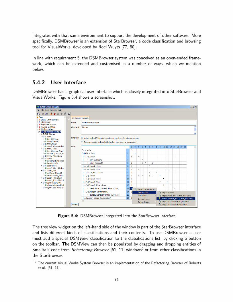
integrates with that same environment to support the development of other software. Morespecifically, DSMBrowser is an extension of StarBrowser, a code classification and browsingtool for VisualWorks, developed by Roel Wuyts [77, 80].
In line with requirement 5, the DSMBrowser system was conceived as an open-ended frame-work, which can be extended and customised in a number of ways, which we mentionbelow.
5.4.2 User Interface
DSMBrowser has a graphical user interface which is closely integrated into StarBrowser andVisualWorks. Figure 5.4 shows a screenshot.
Figure 5.4: DSMBrowser integrated into the StarBrowser interface
The tree view widget on the left-hand side of the window is part of the StarBrowser interfaceand lists different kinds of classifications and their contents. To use DSMBrowser a usermust add a special DSMView classification to the classifications list, by clicking a buttonon the toolbar. The DSMView can then be populated by dragging and dropping entities ofSmalltalk code from Refactoring Browser [61, 11] windows9 or from other classifications inthe StarBrowser.
9 The current Visual Works System Browser is an implementation of the Refactoring Browser of Robertset al. [61, 11].
71

By using the classification model [80], DSMBrowser gives developers the ability to selectarbitrary entities of Smalltalk code as the modules to confront in a DSM. This helps themto focus on the implementation parts of their choice. It is even possible to group modulesacross multiple hierarchies. For instance, one can easily study the dependencies between asingle class and a whole package by simply adding the class (without its own surroundingpackage) and the package to a DSMView classification.
Once the DSMView has been populated a tree-based DSM visualisation will show up inthe right-hand side of the window. This visualisation offers all the interactivity featureswe described earlier. Modules can be dynamically collapsed and/or expanded to supporthierarchical and lateral navigation. Furthermore, context menus – like the one on thescreenshot in figure 5.4 – offer specific functionality with regard to individual modules ordependencies. Examples include opening a Refactoring Browser to look at source code,opening a Trippy inspector [106] to inspect an object or running a metaprogram against aset of dependencies.
5.4.3 DSM Model
Before DSMBrowser can visualise the system formed by the selected source code entities,it must process the code to build an in-memory representation of the modular structure ofthe system and all occurring dependencies. This DSM model will then back the on-screenvisualisation and can be employed by metaprograms as an API to reason about the system.
Figure 5.5, on the next page, shows a simplified UML class diagram [103] of the architectureof the DSM model. To reflect the hierarchical structure of studied code entities, the designuses the Composite pattern [22]. In a nutshell the architecture is set up as follows:
• all components in the hierarchy are represented by instances of the Module class;
• the diagram as a whole is an instance of the DSM class, a subclass of Module;
• all Module instances are composites that can contain other Module instances as theirparameters (or submodules);
• every Module instance holds a reference to its parent Module and to its subject:
– the subject is the source code entity that the Module instance represents,
– the subject of a DSM object is a DSMView classification;
• a Dependency instance represents an implementation-level dependency, from the sub-ject of its from- (or source) Module instance, to the subject of its to- (or target)Module instance:
– it contains references to those Module instances, as well as a weight value (whichdefaults to 1),
72

– the Dependency class represents generic dependencies, subclasses can be definedto represent different types of dependencies (possibly with adjusted weights);
• A DSM instance contains a reference to a DependencyDictionary which indexes De-pendency objects by their source and their target Module.
subject[1]parameters[*] : Moduleparent[1] : Module
Module
parent
1
parameters*
-dependencyDictionary[1]
DSM
from[1] : Moduleto[1] : Moduleweight[1] : Integer
Dependency*
from
1
*
to
1
dependenciesBySource[*] : DependencydependenciesByTarget[*] : Dependency
DependencyDictionary
1 1
1*
1*
Figure 5.5: UML class diagram [103] for the DSM model architecture (simplified)
DSMBrowser extends the service architecture of StarBrowser, which implements the Visitordesign pattern [22]. To build a DSM model for selected entities of code, DSMBrowser usestwo important services.
First, a service that determines the children of the subject of a module (e.g.: the methodsof a class), is used to construct a tree representation. This tree is a parallel representationof the hierarchical structure of the code entities. Building the tree is a recursive process: forevery module the children of its subject are determined and these children then become thesubjects of the submodules of the module. The process starts with the subject of the DSM,which is a DSMView classification whose children are the root code entities (the ones theuser dragged and dropped into the classification). The process stops when the bottom ofthe hierarchy is reached.
Once the tree is completed, DSMBrowser uses a service which determines the dependenciesoriginating from each module in the tree. The dependencies are stored in the Dependency-Dictionary of the DSM. Because the target of some dependencies might not be present inthe classification (e.g.: a class might inherit from a class that is contained in a package thatwas not added to the DSMView), users can choose to add a “virtual” module that acts asa placeholder for external dependency targets10.
10 This feature was inspired by the work of Sullivan et al. [72], which is discussed in Chapter 4 (section 4.3).
73

The DSM Module design is conceptually independent of the Smalltalk language because alllanguage specific behaviour is implemented in the services. Therefore, the design could bestraightforwardly reimplemented in another DSM-browser to target another object-orientedprogramming language. Furthermore, future versions of DSMBrowser could be extendedwith support for other languages by using intermediary libraries.
5.4.4 Smalltalk Language Support
In DSMBrowser, pretty much any entity of Smalltalk source code can act as a modulein the DSM diagram. We support bundles, packages, classes, namespaces and methods.Moreover, we differentiate meta classes from regular classes, class extensions from classdefinitions and namespace extensions from namespaces definitions.
DSMBrowser can express various kinds of relationships among source code entities as de-pendencies. Currently we support message sends, class name references, inheritance rela-tionships, class extensions and namespace relationships. New kinds of dependencies canbe added by defining new subclasses of Dependency and extending the dependency service.A possible candidate is a dependency for overriding relationships (i.e.: from an overridingmethod to the overridden method), which would be trivial to add.
The dependency service tracks the targets of dependencies using different techniques de-pending on the type of dependency. Target tracking is exact for all types expect messagesends. Because Smalltalk is a dynamically typed language it is not easy to determine thetype of the object a message is being sent to. Currently, we use a fairy naıve heuristicthat creates dependencies to all classes that implement a method with the same name asthe message that is being sent. Obviously the performance of this heuristic is rather poor,especially when common Smalltalk methods (e.g.: new, initialize, release, etc.) areconcerned. However, experiments have shown that this does not at all render the tooluseless. This problem is entirely due to the Smalltalk typing system and would not occurin a similar code browser for a statically typed language. Moreover, future versions of theDSMBrowser could use more sophisticated heuristics, for instance based on the techniquesused in RoelTyper [78], a tool that infers the types of instance variables in Smalltalk usingadvanced heuristics.
5.4.5 Analysis Features
The choice for Smalltalk, as the implementation language of DSMBrowser, made it easy toequip the tool with the metaprogramming-based analysis features we specified earlier (see5.3.2.3). Smalltalk’s metaprogramming support and the open VisualWorks environment en-able users to implement analysing metaprograms in plain Smalltalk. However, DSMBrowserdoes provide a number of facilities that considerably simplify that task.
74
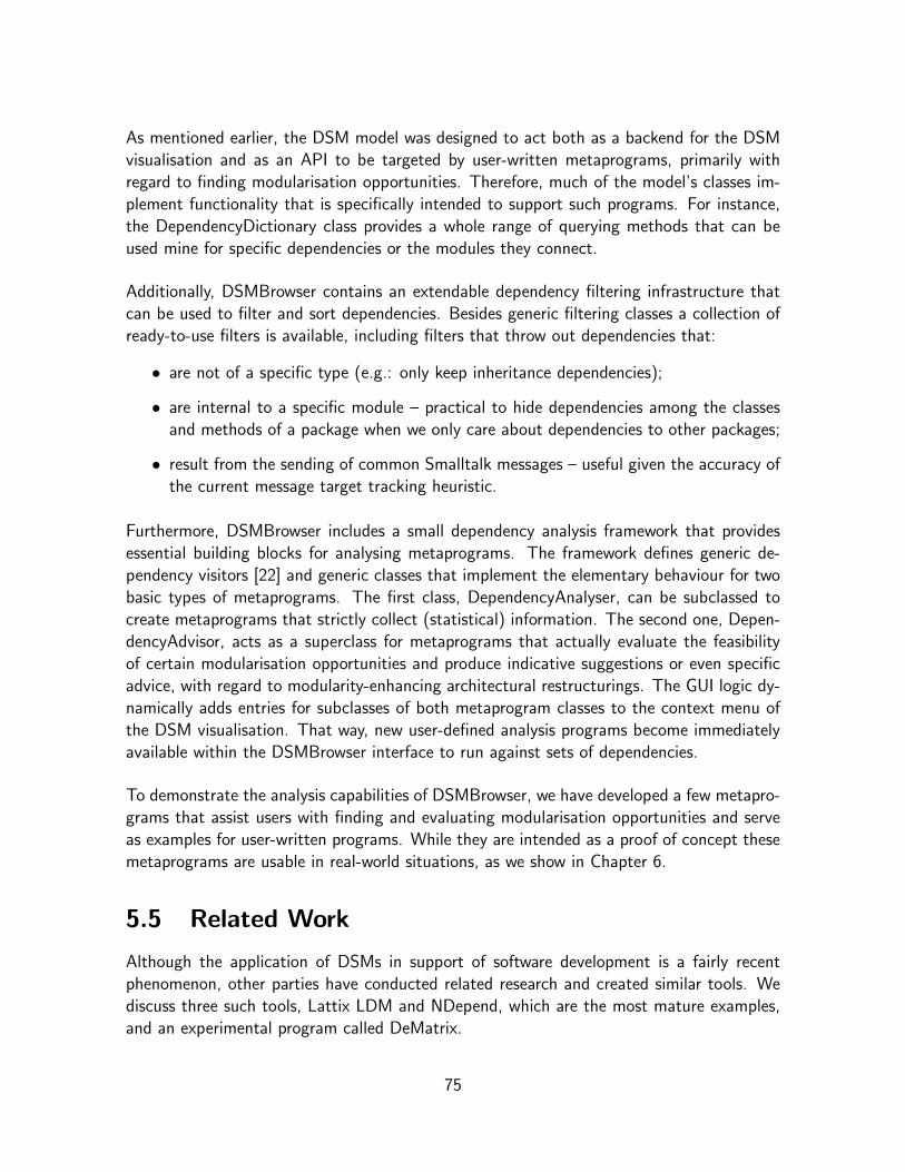
As mentioned earlier, the DSM model was designed to act both as a backend for the DSMvisualisation and as an API to be targeted by user-written metaprograms, primarily withregard to finding modularisation opportunities. Therefore, much of the model’s classes im-plement functionality that is specifically intended to support such programs. For instance,the DependencyDictionary class provides a whole range of querying methods that can beused mine for specific dependencies or the modules they connect.
Additionally, DSMBrowser contains an extendable dependency filtering infrastructure thatcan be used to filter and sort dependencies. Besides generic filtering classes a collection ofready-to-use filters is available, including filters that throw out dependencies that:
• are not of a specific type (e.g.: only keep inheritance dependencies);
• are internal to a specific module – practical to hide dependencies among the classesand methods of a package when we only care about dependencies to other packages;
• result from the sending of common Smalltalk messages – useful given the accuracy ofthe current message target tracking heuristic.
Furthermore, DSMBrowser includes a small dependency analysis framework that providesessential building blocks for analysing metaprograms. The framework defines generic de-pendency visitors [22] and generic classes that implement the elementary behaviour for twobasic types of metaprograms. The first class, DependencyAnalyser, can be subclassed tocreate metaprograms that strictly collect (statistical) information. The second one, Depen-dencyAdvisor, acts as a superclass for metaprograms that actually evaluate the feasibilityof certain modularisation opportunities and produce indicative suggestions or even specificadvice, with regard to modularity-enhancing architectural restructurings. The GUI logic dy-namically adds entries for subclasses of both metaprogram classes to the context menu ofthe DSM visualisation. That way, new user-defined analysis programs become immediatelyavailable within the DSMBrowser interface to run against sets of dependencies.
To demonstrate the analysis capabilities of DSMBrowser, we have developed a few metapro-grams that assist users with finding and evaluating modularisation opportunities and serveas examples for user-written programs. While they are intended as a proof of concept thesemetaprograms are usable in real-world situations, as we show in Chapter 6.
5.5 Related Work
Although the application of DSMs in support of software development is a fairly recentphenomenon, other parties have conducted related research and created similar tools. Wediscuss three such tools, Lattix LDM and NDepend, which are the most mature examples,and an experimental program called DeMatrix.
75

5.5.1 Lattix LDM
Lattix, Inc. was the first company to release a commercial support tool for software devel-opment which applies DSMs as abstract representations of software implementations. Theproduct is called Lattix LDM [95, 26] and is primarily promoted as a tool for analysingand managing large-scale software development projects. Lattix LDM and its underlyingmethodology have been demonstrated in talks at conferences [63, 64] and in a number ofarticles [41, 62, 65]. We have experimented with a trial version of Lattix LDM11.
Lattix LDM reverse engineers Java, C/C++ and .NET code to DSM diagrams and comesas a stand-alone application (for Windows or Linux) and as a plug-in for the Eclipse devel-opment environment [92]. Figure 5.6 shows a screenshot of the Eclipse plug-in displaying aDSM visualisation of the Apache Ant [87] source code. We created this DSM by reproducingthe procedure explained in [41].
Figure 5.6: Lattix LDM [95] Eclipse plug-in showing a DSM for Apache Ant [87]
The user interface of Lattix LDM uses a tree-based DSM visualisation, which aggregatesclasses per package level and allows packages to be collapsed and expanded. While this was
11 Version 2.7.5; while version 3.1 was recently released, licensing constraints do not allow us to use it.
76

a source of inspiration for DSMBrowser, Lattix does not offer the same level of detail, as itdoes not document dependencies below the level of classes.
Lattix computes package-level dependencies by summing class-level dependencies. Class-level dependency values (which are referred to as dependency strengths) are numerical andcan be configured to be knowledge-based on usage-based. The available documentationlacks a formal explanation of both configurations, but as far as we can tell the knowledge-based configuration only takes into account which classes “know” one another, while theusage-based configuration expresses the degree to which classes use each other’s functional-ity. Knowledge-based dependency strengths seem to be limited to a scale from 0 to 2. Theusage-based configuration results in a much wider range of dependency strengths and clearlyprovides a more detailed approximation of implementation level dependencies. However, dueto the lack of method-level dependencies, even Lattix LDM’s usage-based configuration failsto provide the same level of detail DSMBrowser offers.
Other notable features of Lattix LDM include a number of dependency filtering settingsand the definition of design rules12 to capture and enforce architectural intent. Softwarearchitects can create design rules with Lattix LDM to express the nature of dependenciesbetween subsystems or classes. Dependencies that violate such design rules are then high-lighted in the visualisation.
The classification model [80] used in DSMBrowser allows the user to confront any mix ofarbitrary source code entities in a DSM. In comparison, Lattix LDM does not offer the samelevel of flexibility.
While it provides various statistics and metrics13 to analyse software systems, Lattix lackssupport for analysis through metaprogramming and does not provide suggestions with regardto modularisation opportunities.
5.5.2 NDepend
NDepend [99], a product of Smacchia.com s.a.r.l., is another commercial software devel-opment tool that applies DSM diagrams14. It is a dependency management tool that isintended to facilitate controlling the complexity, quality and evolution of source code. NDe-pend exclusively targets the .NET software development platform [98] and integrates withthe Microsoft Visual Studio IDE [97].
The tool analyses source code and compiled .NET assemblies to generate a reports and
12 Refer to Chapter 2 (2.3.3) for an explanation of the concept of design rules.13 These metrics do not include Net Option Value calculation.14 This information is solely based on texts on the NDepend website [99], as we have not experimented
with NDepend ourselves.
77

interactive graphical visualisations, based on tree-based DSMs and other diagrams. It alsoincludes over 60 predefined metrics to analyse different aspects of software implementations.Moreover, it provides metaprogramming facilities by means of an SQL-like query languagecalled Code Query Language (CQL), which allows users to write queries against the codestructure of .NET applications and which can be used to write custom metrics. This query-based approach differs considerably from the metaprogramming API of DSMBrowser. Whichapproach is superior in practice cannot be decided at present.
5.5.3 DeMatrix
DeMatrix [2] is a tool created by Sushil Bajracharya et al. at the University of California,Irvine. It was developed in connection with a larger research project that aims to createan infrastructure, named Sourcerer [3, 101], for large-scale analysis of open source coderepositories. DeMatrix is a front-end for Sourcerer that visualises software using DSMs.
Figure 5.7: DeMatrix applet [2] displaying a DSM for the source code of JAPAN [93]
78

Currently DeMatrix is only available as a Java applet embedded on a demonstration web-page [2]. The applet displays DSM visualisations of Java source code of various open sourceprojects hosted at SourceForge [100]. The screenshot in figure 5.7, on the previous page,shows the DeMatrix applet visualising the code of the JAPAN [93] project.
DeMatrix provides a basic, fairly static visualisation based on (binary) DSMs and no analy-sis features. The design parameters, which are confronted in the DSM, correspond to Javaclasses. Modules, corresponding to packages, are indicated using yellow bordered boxes onthe diagonal. The DSM is not tree-based so packages cannot be collapsed or expanded.The module level can be shifted to correspond to a higher or a lower package level, whichrespectively results in larger or smaller module boxes but does not otherwise alter the visu-alisation.
5.6 Conclusions
The main contributions of the work we presented here are the rationale for a novel DSM-based support tool for OOSD and DSMBrowser, a prototype implementation of such a tool.
As part of the rationale we presented five essential requirements for a dependency manage-ment tool for OOSD, following from observations about the discipline. Considering thoserequirements we concluded that the ideal solution would be to combine tree-based DSM vi-sualisations and metaprogramming-based analysis facilities in an extendable, IDE-integratedsource-code browser. While there are other DSM-based support tools for software develop-ment, this combination of features forms an innovative and powerful approach.
DSMBrowser is an experimental implementation of this approach, applied to the Smalltalklanguage. It seamlessly integrates with StarBrowser and the VisualWork environment andhas excellent support for the modularity and dependency characteristics of Smalltalk andobject-oriented programming languages in general. The tool provides practical facilities thatenable users to write simple, ad-hoc metaprograms to analyse software systems and to findand evaluate modularisation opportunities which improve software design.
Despite its experimental status, the case studies we discuss in Chapter 6 demonstrate thatits unique combination of features makes DSMBrowser highly useful in real-world situations.
DSMBrowser can also serve as a test bed for future research with regard to applications ofDSMs in support of software development. In Chapter 7 (section 7.3) we formulate somedirections for this future work.
79

Chapter 6
DSMBrowser Case Studies
This chapter discusses a number of case studies that demonstrate how software developerscan use DSMBrowser, the DSM-based source code browser we presented in the previouschapter, in real-world situations and how they can benefit from that. The case studies focuson the exploration of unknown source code and on common dependency management tasks.The most prominent contribution we present here is formed by metaprograms that automatethe task of finding and evaluating modularisation opportunities.
6.1 Introduction
In Chapter 5 we introduced a rationale for a novel support tool for Object-Oriented Soft-ware Developments (OOSD) in the form of an extendable DSM-based source code browserwith analysis capabilities based on metaprogramming. We also presented a prototype im-plementation of such a tool – named DSMBrowser – and we made a number of claims andassumptions with regard to the utility of this or future similar tools.
To demonstrate the prototype and validate our claims and assumptions, this chapter presentsa number of case studies. Each case study is situated in a realistic context related to OOSDand presents a usage scenario which shows how and why software developers can benefitfrom using DSMBrowser in that context. Everything is illustrated with concrete examplesand the usage scenarios offer tutorial-style explanations of how we propose to approachthose.
We start out with an exploration case study in section 6.2. While supporting the explorationof unknown source code is not the primary goal of DSMBrowser, the scenario we discusshere helps to explain how the basic visualisation and navigation features can be used. Next,in section 6.3 we consider case studies regarding dependency management. The first casestudy deals with gathering of dependency information and the next ones deal with searchingand evaluation of modularisation opportunities through metaprogramming. We concludethis chapter in section 6.4.
80
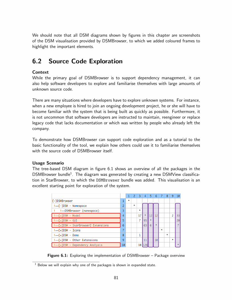
We should note that all DSM diagrams shown by figures in this chapter are screenshotsof the DSM visualisation provided by DSMBrowser, to which we added coloured frames tohighlight the important elements.
6.2 Source Code Exploration
ContextWhile the primary goal of DSMBrowser is to support dependency management, it canalso help software developers to explore and familiarise themselves with large amounts ofunknown source code.
There are many situations where developers have to explore unknown systems. For instance,when a new employee is hired to join an ongoing development project, he or she will have tobecome familiar with the system that is being built as quickly as possible. Furthermore, itis not uncommon that software developers are instructed to maintain, reengineer or replacelegacy code that lacks documentation or which was written by people who already left thecompany.
To demonstrate how DSMBrowser can support code exploration and as a tutorial to thebasic functionality of the tool, we explain how others could use it to familiarise themselveswith the source code of DSMBrowser itself.
Usage ScenarioThe tree-based DSM diagram in figure 6.1 shows an overview of all the packages in theDSMBrowser bundle1. The diagram was generated by creating a new DSMView classifica-tion in StarBrowser, to which the DSMBrowser bundle was added. This visualisation is anexcellent starting point for exploration of the system.
Figure 6.1: Exploring the implementation of DSMBrowser – Package overview
1 Below we will explain why one of the packages is shown in expanded state.
81

Because it is not convenient to study all parts of the system simultaneously, the first step isto select which parts (packages) will be investigated first. The inter-package dependenciesshown in the columns and rows of the DSM are helpful to make this choice.
By looking at the columns, we see which packages are targeted the most by dependenciesoriginating from other packages. Clearly some packages are more“popular”than others. Ata glance, there are five popular packages: Namespace, Model, GUI, StarBrowser2 Ex-
tensions and Dependency Analysis. Assuming that the packages are named accordingto their contents or functionality we can suspect that the Namespace package only containsnamespace definitions. By simply expanding the package – as we did on the figure – wecan establish that this is indeed the case. We can now conclude that the high number ofdependencies to this package is simply caused by the fact that every class in the system isdefined within the DSMBrowser namespace2. Clearly the Namepace package is uninterestingfrom a functional point of view and does not require further investigation. Therefore, in theremainder of our scenario we only consider the other four popular packages.
By looking at the rows we see that the dependency interest is mutual, as the popular pack-ages are also the ones which have the most dependencies to others. We can thus concludethat some packages are heavily dependent on one another, while others are relatively in-dependent. Although the relative independence of a package does not guarantee that itis functionally unimportant, it does signify that we can study it in isolation from others.Consequently, it is probably wise to explore the set of four tightly connected packages firstand to leave the independent ones for later.
Thanks to the classification model of DSM/StarBrowser, studying an arbitrary subset ofa system is easy. We create a new DSMView and populate it with the four packages bydragging and dropping. Now we have limited the scope of our investigation, we can use thenavigation features of DSMBrowser to quickly learn more about the system. By collapsingand expanding different modules, different cross-sections of the system can be visualised.For example, we could end up with the visualisation shown by figure 6.2 on the next page.
Having drilled down the level of classes and methods we can now start to investigate thesystem in more detail. Object-orientation demands that objects have intrinsic responsibil-ities but cooperate to implement the functionality of the system. With such principles inmind, we can expect that classes, or methods, with high incoming dependency values arerelatively more important for the functioning of the system than others. Moreover, classesor methods which lack all incoming dependencies are likely to contain only “dead” code.
2 Right-clicking on the Namespace package and selecting the“Inspect all dependencies to here”option fromthe context menu would reveal that the package is indeed only targeted by namespace dependencies.
82

Figure 6.2: Exploring the implementation of DSMBrowser – Package subset
High outgoing dependency values are an indication of the entities that tie the system to-gether, especially when dependencies cross the borders of surrounding entities. For instance,a class with many dependencies to classes in other packages is likely to be an importantjunction in the system.
Cleary, dependency values in the visualisation provide useful insights. While studying sourcecode remains important to gain a full understanding of the system, the dependency valuescan act as a guide to explore the source code in a pragmatic way.
Guided by dependency values we can now browse through the system to find code entitiesthat require further investigation. For instance, we may notice that the menu method hasrelatively more outgoing dependencies than the other methods of the DependencyCell
class. For example it has 8 inter-package dependencies to the Model package. We mightwant to look at the source code of the menu method to find out what is going on. Onthe other hand, we can also inspect the dependencies themselves. To investigate selectedcode entities or sets of dependencies we can use the inspection features of DSMBrowserwhich are offered in context menus, as show in figure 6.2. These features allow us to moveback and forth between the DSM visualisation and Refactoring Browser [61, 11] windows– to look at source code – or Trippy inspector [106] windows – to inspect dependencies ormodules.
By continuing to explore the system in this fashion we can quickly learn to find our wayaround its principal components and gain understanding of its inner workings.
83

6.3 Dependency Management
Software developers, especially project leaders and software designers, deal with a wide va-riety of responsibilities related to dependency management. These responsibilities rangefrom non-intervening coordination tasks to interventions in design or implementation. Inthis section we demonstrate how DSMBrowser can assist developers in such tasks.
In order to support coordination and communication among involved parties, dependencymanagement requires that efforts are made to know and to keep track of implementation-level dependencies, throughout the lifecycle of a software product. In the case study in 6.3.1we show how DSMBrowser can support these efforts. As an example we look at trackingdependencies to a third-party framework.
Dependency management also requires that opportunities for improved modularisation aredetected, evaluated and pursued at various development stages. Pursuing such opportuni-ties, through interventions in design or implementation, results in dependency minimisationsor eliminations. In the case studies in 6.3.2, we show how the metaprogramming features ofDSMBrowser can help developers to find and evaluate modularisation opportunities in theform of local architectural restructurings.
6.3.1 Tracking Framework Dependencies
ContextIn section 5.2 of Chapter 5 we stated that dependency management is all the more importantwhen parties with different (commercial) interests – such as other companies – are involved.As an illustration, we pointed out that depending on a third-party framework can be liketracking a moving target. In this scenario, we return to that example to demonstrate howDSMBrowser can help developers to keep track of framework dependencies.
Many companies use a framework supplied by a large industry player – for instance, Mi-crosoft’s .NET framework [98] or Sun’s J2EE platform [102] – to build their own softwareproducts. These client companies, especially the smaller ones, are unlikely to have a biginfluence on future development of the framework. As a result, it may be unavoidable thatnew versions of the framework introduce changes that are incompatible with the applica-tions that depend on it. Of course, the client companies can choose to stick with an olderversion of the framework, but that way they cannot benefit from improvements and bug-fixes provided by new versions. Consequently, sooner or later at least part of the dependantapplications will be migrated to a new version.
Usually the framework supplier provides migration support to its clients – at the very least,breaking changes in new framework versions will be documented – but in the end, it willbe up to the programmers of the client companies to solve incompatibility problems on the
84
implementation level. This requires insight into the locations and nature of dependenciesto the framework.
Even when a client company does have a say, or is otherwise granted participation in thedevelopment of the framework, incompatibilities can only be avoided through intense com-munication and coordination, based on precise knowledge about implementation-level de-pendencies (e.g.: which types of dependencies occur how frequently in which locations andwhy).
We now illustrate how DSMBrowser can assist the users of a third-party frameworks to ac-quire such knowledge by explicitly tracking implementation-level dependencies to the frame-work. As an example, we investigated how the IntensiVE tool suite [30, 49, 48] depends onthe HotDraw framework [10].
Usage ScenarioFigure 6.3 shows the DSM diagram we generated. We used two dependency filters in theprocess, one to filter out common message sends and another one to hide all internal de-pendencies among the packages of the Intensional Tools bundle. The former basicallyperforms a kind of noise reduction on our measurements by throwing out unreliable depen-dencies3. The latter helps to focus on what is important here, namely the dependencies tothe HotDraw framework package.
Figure 6.3: Tracking dependencies from IntensiVE (Intensional Tools) to the HotDrawframework
Clearly, the dependencies to classes of the HotDraw framework package are concentratedin the Intensional Visualisation package, which is not surprising since HotDraw is a
3 Common message sends (e.g.: new, initialize, release, add:, etc.) cause a lot of false positivesdue to the dynamical typing system of Smalltalk and the naivety of the of the dependency target findingheuristic in the current version of DSMBrowser.
85

framework for drawing 2D graphics. However, the discovery of the few dependencies thatoriginate from other packages – which do not deal with graphical visualisation – could beof greater importance, as the IntensiVE developers might not expect them there.
By expanding modules we can easily drill down to find out which classes, or even methods,are involved on both sides of the dependencies. On the one hand, tracking the sources ofthe dependencies tells us exactly which parts of IntensiVE depend on HotDraw functionalityand how they do so. On the other hand, tracking the targets informs us about which specificparts of the framework are used by IntensiVE.
This kind information is of great value to both parties for numerous reasons, for instance:
• it is helpful when IntensiVE needs to be changed to work with a new version ofHotDraw, as all the HotDraw-dependant locations are known;
• it makes documentation about changes in a new HotDraw version – supplied by thecreators of the framework – a lot more useful, because the documentation can becompared with a list of all parts of HotDraw IntensiVE depends on, to quickly findout if and where there are breaking changes;
• it provides a suitable basis for communication, cooperation and coordination betweenboth parties (e.g.: the IntensiVE developers can accurately inform the HotDraw cre-ators about which parts of the framework they would like to remain unchanged);
• it helps to define which parts of HotDraw (or other frameworks) should be includedwhen IntensiVE is finalised and packaged as a product to be supplied to customers.At the same time, it also indicates which dependencies need to be eliminated if theframework cannot be included in the distribution (e.g.: due to licensing constraints).
6.3.2 Finding and Evaluating Modularisation Opportunities
In what follows we demonstrate how DSMBrowser can assist developers to improve themodularity of existing software systems or during the implementation phase of systems thatin development. By exploiting the metaprogramming facilities of DSMBrowser, we havedeveloped metaprograms that automate the manual exploration, pattern detection, analysisand evaluation process to find feasible opportunities for improved modularisation. The taskof implementing opportunities that have been found worthwhile remains up the users.
Modularisation OpportunitiesThese opportunities are implementation-level changes that could potentially improve mod-ularity through minimisation or even elimination of dependencies. Specifically, we focus onlocal architectural restructurings by means of common object-oriented strategies. We studytwo general types of local restructurings.
86
First, we consider how the introduction of local indirections within modules can lower ex-ternal dependencies. These restructurings reroute, canalize or centralise dependencies toexternal modules via a newly created local indirection entity. That way, multiple externaldependencies are replaced by a single one, originating from the indirection. The local indi-rection acts as an interface through which the external module can be accessed. As a result,changes in the external module are less likely to require changes in all dependent entities butonly require changes in the indirection entity. To find feasible indirection opportunities wehave implemented two fully functional metaprograms, one which deals with message senddependencies and another one for inheritance dependencies. We will demonstrate both insmall case studies.
Secondly, we consider how dependencies to external modules can be entirely eliminated bylocally duplicating code that implements required behaviour. These restructurings can ef-fectively separate or decouple modules. While we have not implemented them ourselves,we present an approach to create metaprograms to find opportunities for the eliminationof message send and inheritance dependencies through code duplication, starting from theindirection metaprograms.
MetaprogramsThe metaprograms we wrote analyse user-selected sets of dependencies and infer indicativesuggestions or even specific advice, with regard modularity enhancing restructurings theyconsider to be feasible. We wrote these metaprograms in plain Smalltalk, using the analysisand metaprogramming facilities of DSMBrowser (the DSM Model API, dependency filtersand the generic metaprogram classes) which we discuss in Chapter 5 (5.4.5).
Our metaprograms serve as a proof of concept, rather than universally applicable solutions.They use overly-general or naive assumptions and crisp threshold parameters to evaluate thefeasibility of modularisation opportunities. While the current metaprograms can producemeaningful modularisation suggestions in real-world situations – as we will demonstrate– users will have to fine-tune the parameters and implement additional, domain specificdecision rules, to apply them in specific, mission-critical environments.
AssumptionsIn our metaprograms we make the assumption that the user wants to minimise dependencieswhich cross the boundaries of packages. In other words, the level of packages is consideredto be the“separation point”: the place where subsystems meet (e.g.: own code versus third-party code) and where strong dependencies are unwanted. It would however be trivial tochange the metaprograms to lift the separation point to the bundle level or to drop it tothe class level.
To illustrate the architectural restructurings we propose, we use UML [103] class diagrams
87

with simplified “before” and “after” situations involving a package A and a package B. Inthese diagrams:
• The studied dependencies originate from package A and target package B;
• Package A considered to contain code which the user has full control over;
• Dependencies to package B are considered unwanted, for instance because it is con-trolled by a third party;
• In the “before” situation the packages contain 1 or 3 classes each. The number ofclasses per package should be interpreted as follows:
– when a package X contains 1 class that should be read as “... few classes inpackage X ...”,
– when a package Y contains 3 classes that should be read as“... many classes inpackage Y ...”,
where the definitions of few and many are governed by user-configurable thresholdparameters of the metaprograms.
6.3.2.1 Minimising Dependencies with Indirections
6.3.2.1.1 Message Send Dependencies
RestructuringsIn this case study we present a metaprogram that suggests local architectural restructuringsto minimise message send dependencies. All message send dependencies are caused bymethod calls which request the execution of behaviour or perform data access. We cannotsimply eliminate these dependencies without affecting the functionality of the software.However, message sends that cross module boundaries can be reduced by introducing localindirections.
Given the assumptions discussed above, our aim is to lower the number of inter-packagemessage sends by introducing indirections in the package of origin. Such indirections canbe introduced on the level of classes and on the level of methods.
On the level of classes, we can use simple design patterns [22] to introduce local indirectionclasses to reroute message sends. We distinguish four situations with regard to messagesends from a package A to a package B, based on the number of involved classes:
• Many-to-Few: The message sends originate from many classes in package A andtarget few classes in package B.In this case the dependency from package A to package B can be lowered by applying
88

the Proxy design pattern [22]. The idea is to introduce a local proxy-class in packageA, for each of the few classes which are targeted in package B. Each proxy-class shouldcontain wrapper methods for all methods of the class of package B it represents andwhich are called from package A. That way all calls to package B can be reroutedvia local proxies. As a result there will only be a single inter-package message senddependency for every targeted method. This is illustrated by the UML diagram infigure 6.4a;
• Many-to-Many: The message sends originate from many classes in package A andtarget many classes in package B.In this case the dependency from package A to package B can be lowered by applyingthe Facade design pattern [22]. The idea is to introduce a single facade-class inpackage A, which contains wrapper methods for all methods of the many classes inpackage B, which are called from package A. That way all calls to package B canbe rerouted via the local facade. As a result there will only be a single inter-packagemessage send dependency for every targeted method. This is illustrated by the UMLdiagram in figure 6.4b;
• Few-to-Few: The message sends originate from few classes in package A and targetfew classes in package B.In this case the introduction of indirections on the class-level is not useful;
• Few-to-Many: The message sends originate from few classes in package A andtarget many classes in package B.In this case the introduction of indirections on the class-level is not useful.
In the cases where there is no useful class-level indirection possible, method-level indirectionscan be considered to minimise message sends from a package A to a package B. Method-level indirections are simple, individual wrapper methods which are introduced into existingclasses of package A, as illustrated by the UML diagram in figure 6.4c. This way thenumber of inter-package message send dependencies can be lowered whenever there aremore messages being send than methods being targeted. The location where the wrappermethod should go is best decided by considering the sources of the calls to the wrappedmethod. We propose to select the class which accounts for the most of those calls as theideal place to insert the wrapper method.
ContextAs an example we look at the message send dependencies from the IntensiVE tool suite[30, 49, 48] to SOUL [79, 76]. The implementation of IntensiVE depends heavily on SOULand there is no way that local architectural restructurings can completely change that.However, the introduction of indirections can significantly lower the dependencies. Moreover,such indirections provide a local interfaces for SOUL components and thereby limit the effectof changes in SOUL for dependent components in IntensiVE.
89

Package B
ClassB1 ClassB2 ClassB3
Package A
ClassA1
Package A
ClassA1
Package B
ClassB1 ClassB2 ClassB3
ClassB_ProxyA1
(a)
Package A
ClassA1 ClassA2 ClassA3
Package A
ClassA1 ClassA2 ClassA3
Package B
ClassB1 ClassB2 ClassB3
Package B
ClassB1 ClassB2 ClassB3
ClassB_FacadeA
(b)
Package B
ClassB1 ClassB2 ClassB3
Package A
+method()
ClassA1
Package B
ClassB1 ClassB3
Package A
+method()
ClassA1
+wrapperMethod()
ClassB2
(c)
Figure 6.4: Lowering inter-package message send dependency by introducing indirections,by means of a proxy class (a), a facade class (b) and an individual wrapper method in an
existing class (c)
90
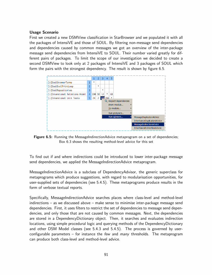
Usage ScenarioFirst we created a new DSMView classification in StarBrowser and we populated it with allthe packages of IntensiVE and those of SOUL. By filtering non-message send dependenciesand dependencies caused by common messages we got an overview of the inter-packagemessage send dependencies from IntensiVE to SOUL. Their number varied greatly for dif-ferent pairs of packages. To limit the scope of our investigation we decided to create asecond DSMView to look only at 2 packages of IntensiVE and 3 packages of SOUL whichform the pairs with the strongest dependency. The result is shown by figure 6.5.
Figure 6.5: Running the MessageIndirectionAdvice metaprogram on a set of dependencies;Box 6.3 shows the resulting method-level advice for this set
To find out if and where indirections could be introduced to lower inter-package messagesend dependencies, we applied the MessageIndirectionAdvice metaprogram.
MessageIndirectionAdvice is a subclass of DependencyAdvisor, the generic superclass formetaprograms which produce suggestions, with regard to modularisation opportunities, foruser-supplied sets of dependencies (see 5.4.5). These metaprograms produce results in theform of verbose textual reports.
Specifically, MessageIndirectionAdvice searches places where class-level and method-levelindirections – as we discussed above – make sense to minimise inter-package message senddependencies. First, it uses filters to restrict the set of dependencies to message send depen-dencies, and only those that are not caused by common messages. Next, the dependenciesare stored in a DependencyDictionary object. Then, it searches and evaluates indirectionlocations, using simple procedural logic and querying methods of the DependencyDictionaryand other DSM Model classes (see 5.4.3 and 5.4.5). The process is governed by user-configurable parameters – for instance the few and many thresholds. The metaprogramcan produce both class-level and method-level advice.
91
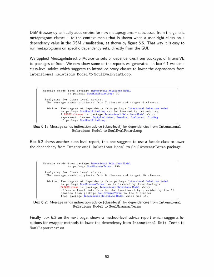
DSMBrowser dynamically adds entries for new metaprograms – subclassed from the genericmetaprogram classes – to the context menu that is shown when a user right-clicks on adependency value in the DSM visualisation, as shown by figure 6.5. That way it is easy torun metaprograms on specific dependency sets, directly from the GUI.
We applied MessageIndirectionAdvice to sets of dependencies from packages of IntensiVEto packages of Soul. We now show some of the reports we generated. In box 6.1 we see aclass-level advice which suggests to introduce proxy classes to lower the dependency fromIntensional Relations Model to SoulEvalPrintLoop.
� �Message sends from package Intensional Relations Model
to package SoulEvalPrintLoop: 30
Analysing for Class level advice ...The message sends originate from 7 classes and target 4 classes.
Advice: The degree of dependency from package Intensional Relations Modelto package SoulEvalPrintLoop can be lowered by introducing4 PROXY classes in package Intensional Relations Model whichrepresent classes EmptyEvaluator, Results, Evaluator, Bindingof package SoulEvalPrintLoop.� �
Box 6.1: Message sends indirection advice (class-level) for dependencies from IntensionalRelations Model to SoulEvalPrintLoop
Box 6.2 shows another class-level report, this one suggests to use a facade class to lowerthe dependency from Intensional Relations Model to SoulGrammarTerms package.
� �Message sends from package Intensional Relations Model
to package SoulGrammarTerms: 190
Analysing for Class level advice ...The message sends originate from 8 classes and target 10 classes.
Advice: The degree of dependency from package Intensional Relations Modelto package SoulGrammarTerms can be lowered by introducing aFACADE class in package Intensional Relations Model whichoffers a local interface to the functionality provided by the 10classes from package SoulGrammarTerms to the 8 classesfrom package Intensional Relations Model which use it.� �
Box 6.2: Message sends indirection advice (class-level) for dependencies from IntensionalRelations Model to SoulGrammarTerms
Finally, box 6.3 on the next page, shows a method-level advice report which suggests lo-cations for wrapper methods to lower the dependency from Intensional Unit Tests toSoulRepositories.
92
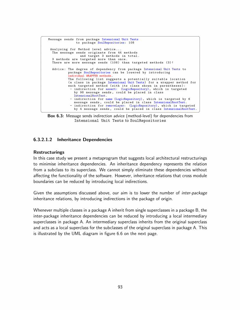
� �Message sends from package Intensional Unit Tests
to package SoulRepositories: 108
Analysing for Method level advice ...The message sends originate from 44 methods
and target 3 methods in total.3 methods are targeted more than once.There are more message sends (108) than targeted methods (3)!
Advice: The degree of dependency from package Intensional Unit Tests topackage SoulRepositories can be lowered by introducingindividual WRAPPER methods.The following list suggests a potentially suitable location(a class in package Intensional Unit Tests) for a wrapper method foreach targeted method (with its class shown in parentheses):- indirection for assert: (LogicRepository), which is targeted
by 98 message sends , could be placed in classIntensionalRootTest.
- indirection for name (LogicRepository), which is targeted by 6message sends , could be placed in class IntensionalRootTest.
- indirection for removeLayer: (LogicRepository), which is targetedby 4 message sends , could be placed in class IntensionalRootTest.� �
Box 6.3: Message sends indirection advice (method-level) for dependencies fromIntensional Unit Tests to SoulRepositories
6.3.2.1.2 Inheritance Dependencies
RestructuringsIn this case study we present a metaprogram that suggests local architectural restructuringsto minimise inheritance dependencies. An inheritance dependency represents the relationfrom a subclass to its superclass. We cannot simply eliminate these dependencies withoutaffecting the functionality of the software. However, inheritance relations that cross moduleboundaries can be reduced by introducing local indirections.
Given the assumptions discussed above, our aim is to lower the number of inter-packageinheritance relations, by introducing indirections in the package of origin.
Whenever multiple classes in a package A inherit from single superclasses in a package B, theinter-package inheritance dependencies can be reduced by introducing a local intermediarysuperclasses in package A. An intermediary superclass inherits from the original superclassand acts as a local superclass for the subclasses of the original superclass in package A. Thisis illustrated by the UML diagram in figure 6.6 on the next page.
93

Package B
ClassB1 ClassB2 ClassB3
Package A
ClassA1
Package A
ClassA1
Package B
ClassB1 ClassB2 ClassB3
ClassB_A1
Figure 6.6: Lowering inter-package inheritance dependency by introducing an intermediarysuperclass
ContextAs an example we look at the inheritance dependencies from the Fuzzy Intensional Viewssoftware [52] to the IntensiVE tool suite [30, 49, 48].
Usage ScenarioFirst, we created a new DSMView classification in StarBrowser and populated it with thepackages of Fuzzy Intensional Views and IntensiVE. To get an overview of the inter-packageinheritance dependencies we used a filter to remove all other dependencies from the DSM.The inheritance relations mainly originated from one package of Fuzzy Intensional Viewsand targeted classes in three packages of IntensiVE. Next we created a second DSMViewto focus on just those packages, figure 6.7 shows the result.
Figure 6.7: Inheritance dependencies from classes of the Fuzzy Predicate Viewspackage to three packages of the IntensiVE tool suite
94

The DSM shows that there are 9 inheritance relations from the Fuzzy Predicate Views
package to the three packages of the IntensiVE tool suite.
To find out if and where indirections could be introduced to lower inter-package inheritancedependencies, we applied the InheritanceIndirectionAdvice metaprogram.
InheritanceIndirectionAdvice is also a subclass of DependencyAdvisor dependencies (see5.4.5), and is thus largely analogous to MessageIndirectionAdvice. It searches places whereit makes sense to introduce an intermediary superclass – as we discussed above – to minimiseinter-package inheritance dependencies.
We applied this metaprogram to the dependencies from the Fuzzy Predicate Views pack-age to each of the three packages of the IntensiVE tool suite. Box 6.4 shows the results.
� �Inheritance relations from package Fuzzy Predicate Views
to package Intensional Relations Model: 7Advice:The degree of dependency from package Fuzzy Predicate Views topackage Intensional Relations Model can be lowered by introducinga new subclass of class AbstractQuantifier of packageIntensional Relations Model in package Fuzzy Predicate Views toact as a local , INTERMEDIARY SUPERCLASS for classes FuzzyAllQuantifier,FuzzyAlmostAllQuantifier, FuzzyMostQuantifier, FuzzyFewQuantifier,FuzzyExistsQuantifier which are currently directly subclassed fromclass AbstractQuantifier of package Intensional Relations Model.
Inheritance relations from package Fuzzy Predicate Viewsto package IV Evaluators: 1
No advice for these packages.
Inheritance relations from package Fuzzy Predicate Viewsto package Saving Mechanism: 1
No advice for these packages.� �Box 6.4: Inheritance Indirection Advice Report
The report shows that the 7 inheritance dependencies from the Fuzzy Predicate Views
package to the Intensional Relations Model package, all target the same superclass(AbstractQuantifier). Hence, an intermediary superclass could bring the inheritancedependencies between those packages down from 7 to 1. The Fuzzy Predicate Views
package only has single inheritance dependencies to the other two packages of IntensiVE,so obviously those dependencies cannot be lowered any further by means of indirections.
6.3.2.2 Eliminating Dependencies with Code Duplication
Duplication of code is generally considered as bad practice because it the hampers mainte-nance and evolution of software systems. Indeed, each new software development paradigmthat has been introduced has provided new abstraction mechanisms that allow us to achieveincreased modularity and reduced code duplication in software implementations.
95

However, there are situations where code duplication is a drastic, yet viable, option to dealwith dependency related issues. For instance, when a software module depends on a smallpart of a large, external module which is otherwise obsolete, outdated or too big to includein distributions, it might be better to locally duplicate the code of that small part. Thatway the dependency to the external module can be entirely eliminated.
The current version of DSMBrowser does not include metaprograms to find and evaluateplaces where dependencies can be eliminated through code duplication. However, the pro-vided APIs should suffice to create such programs. Furthermore, the programs that dealwith indirections, which we discussed above, could serve as a starting point. The majordifference would be that checking for possible code duplication opportunities requires theinspection of second, and higher, degree dependencies, further away from the source of thedependency that is being considered for elimination. This is necessary to determine whetheror not the targeted entity is sufficiently independent from its surroundings to be copied inisolation or with a limited number of supporting entities.
Code duplication can be used to eliminate both message send and inheritance dependencies.
6.3.2.2.1 Message Send Dependencies
Message send dependencies from package A to package B can be eliminated by locally du-plicating the behaviour of the called methods of classes of package B. Duplicated methodscan be inserted into existing classes of package A, or new classes can be created to accom-modate them.
Not all methods can be duplicated in isolation of rest of the class they are part of. Therefore,it may be necessary to duplicate the whole class, possibly with unneeded methods and datastructures stripped out. But the class itself could also be closely dependent of other classesof package B, which would need to be duplicated as well, and so on. Clearly, it is not trivialto decide which duplication efforts are worthwhile.
The duplication of a class to eliminate message send dependencies is illustrated by the UMLdiagram in figure 6.8, on the next page.
6.3.2.2.2 Inheritance Dependencies
Inheritance dependencies from package A to package B can be eliminated by duplicatingthe targeted superclasses in package B as local classes in package A. Again, it is not trivialto decide which classes can be duplicated without requiring too many additional classes tobe copied as well. The duplication of a superclass to eliminate inheritance dependencies isillustrated by the UML diagram in figure 6.9, on the next page.
96
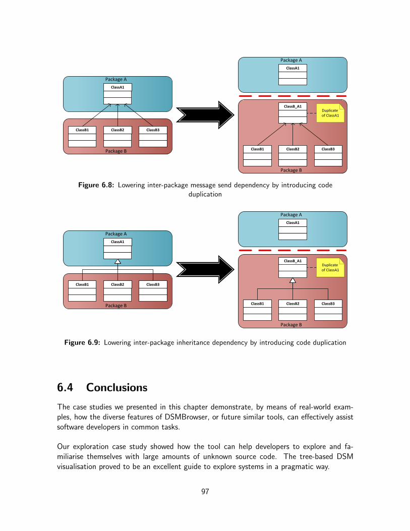
Package B
ClassB1 ClassB2 ClassB3
Package A
ClassA1
Package A
ClassA1
Package B
ClassB1 ClassB2 ClassB3
ClassB_A1Duplicateof ClassA1
Figure 6.8: Lowering inter-package message send dependency by introducing codeduplication
Package B
ClassB1 ClassB2 ClassB3
Package A
ClassA1
Package A
ClassA1
Package B
ClassB1 ClassB2 ClassB3
ClassB_A1Duplicateof ClassA1
Figure 6.9: Lowering inter-package inheritance dependency by introducing code duplication
6.4 Conclusions
The case studies we presented in this chapter demonstrate, by means of real-world exam-ples, how the diverse features of DSMBrowser, or future similar tools, can effectively assistsoftware developers in common tasks.
Our exploration case study showed how the tool can help developers to explore and fa-miliarise themselves with large amounts of unknown source code. The tree-based DSMvisualisation proved to be an excellent guide to explore systems in a pragmatic way.
97
We also demonstrated at large how DSMBrowser facilitates tasks with regard to dependencymanagement. First, we explained how the tool can be used to generate helpful overviewsof dependencies to external systems, such as third-party frameworks. These overviews canserve as a basis for communication and coordination among involved parties. Next, weshowed how the metaprogramming facilities of DSMBrowser can be used to automate theprocess of finding and evaluating different kinds of modularisation opportunities, in the formof local architectural restructurings.
These results validate the claims we made in the previous chapter. Most notably they em-phasise that the concept of an IDE-integrated source-code browser which provides tree-basedDSM visualisations and metaprogramming-based analysis facilities, is indeed a valuable con-tribution to the OOSD field.
In Chapter 7 (section 7.3) we formulate ideas for future enhancements to DSMBrowser andfor more sophisticated metaprograms.
98
Chapter 7
Conclusions
7.1 Summary
In this dissertation we investigated how Design Structure Matrices (DSMs) and relatedtechniques can be applied in the context of software development. The premise of ourwork is that DSM diagrams, through their focus on the modular structure of systems andthe explicit depiction of – the distribution and nature of – dependencies, offer interestingopportunities for innovations on two distinct fronts.
First we have provided an elaborate introduction to DSMs, their origins and application andrelated techniques such as NOV. Next, we presented the two angels of research we havepursued.
The first part of our research covered an exploration of the combination of DSMs and the NetOption Value (NOV) model as a methodology for quantitative assessment of modularity insoftware. First we introduced DSM+NOV Tool, a novel software tool intended to facilitateexperimentation with this methodology. Next, we presented an evaluation of the NOVmodel as a modularity metric for software design, based on experiments on aspect-orientedand object-oriented design pattern implementations. We concluded that the current level ofunderstanding of the NOV model regrettably does not warrant its application it this context.
The second part of our work constituted an investigation of the merits of DSM diagramsas a basis for a novel kind of support tools for software development. We analysed thepossibilities and requirements for a DSM-based support tool for Object-Oriented SoftwareDevelopment (OOSD) and summarised our findings in an extensive rationale, illustratedby a prototype implementation called DSMBrowser. Next, we presented a number of real-world case studies which demonstrate how our prototype, or future similar tools, can assistsoftware developers in common tasks related to source code exploration and dependencymanagement.
99

7.2 Contributions
The work we presented in this dissertation offers the following contributions:
• In Chapter 2 we provided a comprehensive introduction to DSMs and related tech-niques such as NOV. This text offers readers an essential crash course which preparesthem for passive and active use of DSM diagrams for both research and professionalpurposes;
• In Chapter 3 we introduced a novel software tool which facilitates the application ofthe DSM+NOV methodology for design assessments, as well as exploration of themethodology itself. The tool introduces an innovative technique to assess systemsusing NOV and a combination of two DSMs which focus on different hierarchicallevels of the studied system;
• In Chapter 4 we investigated the DSM+NOV methodology as a technique for qualita-tive assessment of software. We introduced a novel approach for NOV measurementand a new assumption for the complexity parameter of the NOV model, both specif-ically aimed at analysis of software implementations. We concluded this evaluationwith a series of observations that led us to strongly question the applicability of theNOV model as a modularity metric for software design;
• In Chapter 5 presented a rationale for a novel DSM-based support tool for OOSD anda prototype implementation of such a tool. As part of the rationale we formulatedessential requirements for a dependency management tool for OOSD and we proposedan approach which combines tree-based DSM visualisations and metaprogramming-based analysis facilities in an extendable, IDE-integrated source-code browser. In ourprototype we successfully applied this approach to support software development inthe Smalltalk language.
• Chapter 6 we discussed case studies which show how DSM-based source browserscan assist software developers in the exploration of unknown source code and independency management tasks. As a demonstration of the metaprogramming facilitiesof our prototype we presented metaprograms that automate the task of finding andevaluating modularisation opportunities based on local architectural restructurings.
7.3 Future Work
In this section we give an overview of future research directions we consider interesting foreach of the two angels we followed in our work.
100

7.3.1 Evaluating Modularity with DSMs
Further research into the NOV model may enhance our understanding of its parametersand outcome and could then ultimately enable us to successfully use it in combinationwith numerical DSMs (NDSMs) and as software metric. However, due to difficulties weexperienced in our experiments with the model, we have significant doubts concerning thechance of success for this research direction.
Therefore, we think it would be better to focus on developing a new quantitative model toassess modularity in design based on DSMs. Such a new model could retain some of theprinciples of NOV but it should be specifically designed to serve as a modularity metric forsoftware design.
7.3.2 DSM-based Support Tools
We have a multitude of ideas with regard to new features for our DSMBrowser tool and/orfuture research into DSM-based support tools in general.
We think that it could be interesting to introduce a time aspect in DSM-based supporttools. This would enable us to use DSMs to visualise the evolution of a software system,rather than working with static representations frozen in time. We could investigate thesepossibilities by extending our tool with a versioning concept. In connection with this idea itmight be interesting to look at the Moose reengineering environment for Smalltalk [54].
Currently our metaprograms are limited to finding and evaluating modularisation opportu-nities based on relatively small local architectural restructurings. An obvious improvementwe could focus on would be to devise more sophisticated metaprograms capable of findingand evaluating modularisation opportunities on a larger scale. For instance, we could tryto detect situations where the introduction of design patterns [22] that encompass muchlarger parts of the system could effectively improve the modularity of the design as a whole.In fact, we could extend our source-code browser to become a full-blown refactoring toolwhich detects opportunities for refactorings based on “bad smells” [21, 31] and integrateswith the refactoring framework of the Refactoring Browser [61, 11].
Until now our DSMBrowser metaprograms only find and evaluate modularisation opportu-nities, leaving the task of pursuing opportunities that have been found worthwhile to thedevelopers themselves. In the future we could try to automate this third phase as well,by further exploiting the metaprogramming features of Smalltalk to let our metaprogramsmake actual changes to the implementation of the studied system. This would allow usersto instantly see the effects of these changes in the DSM visualisation, without first havingto resort to manual source code editing. Furthermore, if this idea is realised in combinationwith the time aspect idea, users would be able to compare “before” and “after” situations.
101

If we integrate DSMBrowser with the Refactoring Browser framework we could let ourmetaprograms trigger the automatic refactorings offered by that framework.
For now our metaprograms are written in a procedural and imperative style and in plainSmalltalk. In the future we could consider to extend DSMBrowser with support for declar-ative metaprogramming using a domain specific language. For instance, it might be inter-esting to investigate whether DSMBrowser can be linked to the SOUL framework [79, 76].If we combine a declarative approach to metaprogramming with support for refactorings wecould use the work of Munoz Bravo [53] as a source of inspiration.
Last but not least, we would like to investigate if DSMBrowser can be used as a basis for aDSM-based aspect mining tool [28].
7.4 Conclusion
In this dissertation we to took the first steps towards the application of Design StructureMatrices (DSMs) in diverse aspects of software development.
On the one hand, our initial expectations with regard to the Net Option Value (NOV) modelproved to be too optimistic. This is shown by the evaluation we presented, which clearlyhighlights the obstacles that hamper the application of the NOV model in the context ofsoftware development. Nevertheless, the tool be developed to support our experimentscan be used for further research into NOV or for applications of DMS+NOV methodologyoutside software development.
On the other hand, the use of DSMs diagrams in support tools proved to be a real success,as demonstrated by the case studies we presented. Therefore, we are convinced that ourrationale for DSM-based source code browsers and our prototype implementation are majorcontributions to the field.
102

Appendix A
The Q(k) distribution
The calculation of Net Option Value (NOV) simulates parallel experimentation on each
Normal distribution
Cumulative distribution function:
F (x ;µ, σ) =1
2
[1 + er f
(x − µσ√2
)](A.1)
Probability density function:
f (x ;µ, σ) =1
σ√2π
e− (x−µ)
2
2σ2 (A.2)
Gauss error function
er f (x) =2√π
x∫0
e−t2dt (A.3)
constituent module of a design (see 2.3.6.2 in Chap-ter 2). The role of the Q(k) distribution is to quantifythe value of the best of k outcomes (resulting from k
experiments) for each module.
Q(k) is defined as the expected value of the high-est realisation (best/maximum draw) of k independentdraws from a standard normal distribution, as long asthe realisation is greater than zero (so only for all pos-itive values in the distribution)1.
The formal definition of the distribution is given byequation A.4, where N(x), given by equation A.5, isthe cumulative distribution function and n(x), given by equation A.6, the probability densityfunction of the standard normal distribution. These functions are respectively the evalua-tion of equation A.1 and equation A.2 for the standard normal distribution (mean µ = 0;standard deviation σ = 1). The Gauss error function, er f (x), is defined by equation A.3.
Q(k) = k
∞∫0
x [N(x)]k−1 n(x) dx (A.4)
N(x) =1
2
[1 + er f
(x√2
)](A.5)
n(x) =1√2π
e−x2
2 (A.6)
1 The distribution of the best of k realisations is common in statistics: it is the distribution of the“maximum order statistic of a sample of size k”. However, in this case the expectation differs from thestandard one, as it is taken only over the range of values above zero (see [5, 7], which cite [42] as areference on order statistics in general).
103

Table A.1 tabulates the values of Q(k) for 0 ≤ k ≤ 100. On the next page, figure A.1shows these values as a graph.
k Q(k)
0 0.000000
1 0.398942
2 0.681037
3 0.888147
4 1.045756
5 1.169705
6 1.270073
7 1.353426
8 1.424153
9 1.485261
10 1.538865
11 1.586488
12 1.629251
13 1.668001
14 1.703387
15 1.735916
16 1.765993
17 1.793943
18 1.820032
19 1.844482
20 1.867475
k Q(k)
21 1.889168
22 1.909692
23 1.929162
24 1.947674
25 1.965315
26 1.982158
27 1.998269
28 2.013707
29 2.028522
30 2.042761
31 2.056464
32 2.069669
33 2.082408
34 2.094713
35 2.106609
36 2.118123
37 2.129277
38 2.140091
39 2.150586
40 2.160777
k Q(k)
41 2.170682
42 2.180316
43 2.189691
44 2.198822
45 2.207720
46 2.216395
47 2.224859
48 2.233121
49 2.241190
50 2.249074
51 2.256781
52 2.264319
53 2.271694
54 2.278914
55 2.285983
56 2.292909
57 2.299696
58 2.306351
59 2.312876
60 2.319278
k Q(k)
61 2.325561
62 2.331728
63 2.337785
64 2.343733
65 2.349578
66 2.355323
67 2.360970
68 2.366524
69 2.371986
70 2.377359
71 2.382647
72 2.387852
73 2.392976
74 2.398022
75 2.402992
76 2.407889
77 2.412713
78 2.417467
79 2.422154
80 2.426774
k Q(k)
81 2.431331
82 2.435824
83 2.440257
84 2.444630
85 2.448945
86 2.453204
87 2.457407
88 2.461557
89 2.465654
90 2.469700
91 2.473697
92 2.477644
93 2.481544
94 2.485397
95 2.489204
96 2.492967
97 2.496687
98 2.500364
99 2.503999
100 2.507594
Table A.1: Values of Q(k) for 0 ≤ k ≤ 100, rounded to the nearest 10−6
104

2.00
2.50
3.00
Q(k) for 0 ≤ k ≤ 100
0.00
0.50
1.00
1.50
0 5 10 15 20 25 30 35 40 45 50 55 60 65 70 75 80 85 90 95 100
k
Q(k)
Figure A.1: Graphed values of Q(k) for 0 ≤ k ≤ 100
105
Bibliography
[1] Christopher Alexander, Sara Ishikawa, Murray Silverstein, et al. A Pattern Language:Towns, Buildings, Construction. Oxford University Press, New York, USA, 1977.ISBN: 0-195-01919-9.
[2] Sushil Krishna Bajracharya. DeMatrix, 2006.URL: http://mine7.ics.uci.edu/repo2/dsm.html.
[3] Sushil Krishna Bajracharya, Trung Ngo, Erik Linstead, Yimeng Dou, Paul Rigor, PierreBaldi, and Cristina Videira Lopes. Sourcerer: A Search Engine for Open Source CodeSupporting Structure-Based Search. In OOPSLA ’06: Companion to the 21st ACMSIGPLAN conference on Object Oriented Programming, Systems, Languages, andApplications, Portland, Oregon, USA, pages 681–682, New York, NY, USA, October2006. ACM Press.ISBN: 1-59593-491-X.DOI: 10.1145/1176617.1176671.
[4] Sushil Krishna Bajracharya, Trung Chi Ngo, and Cristina Videira Lopes. On usingNet Options Value as a Value Based Design Framework. In Kevin J. Sullivan, editor,EDSER ’05: Proceedings of the 7th International Workshop on Economics-DrivenSoftware Engineering Research, pages 1–3. ACM Press, New York, NY, USA, May2005. EDSER ’05 took place on May 15, 2005 as a workshop part of ICSE ’05, the27th International Conference on Software Engineering, May 15-21, 2005, St. Louis,MO, USA.ISBN: 1-59593-118-X.DOI: 10.1145/1083091.1083104.
[5] Carliss Y. Baldwin and Kim B. Clark. Design Rules, Volume 1: The Power of Modu-larity. MIT Press, Cambridge, MA, USA, March 2000.ISBN: 0-262-02466-7.URL: http://mitpress.mit.edu/catalog/item/default.asp?ttype=2&tid=3606.
[6] Carliss Y. Baldwin and Kim B. Clark. The Option Value of Modularity in Design:An Example from ”Design Rules, Volume 1: The Power of Modularity”. HarvardNOM Working Paper No. 02-13; Harvard Business School Working Paper No. 02-078, Harvard Business School, Boston, MA, USA, May 2002.
106

URL: http://ssrn.com/abstract=312404,DOI: 10.2139/ssrn.312404.
[7] Carliss Y. Baldwin and Kim B. Clark. Modularity in the Design of Complex EngineeringSystems. In Dan Braha Ali Minai and Yaneer Bar Yam, editors, Complex EngineeredSystems: Science Meets Technology, Understanding Complex Systems, chapter 9,pages 175–205. New England Complex Systems Institute (NECSI) / Springer-Verlag,2006. Article itself dates from January 2004.ISBN: 3-540-32831-9, 978-3-540-32831-5.URL: http://www.people.hbs.edu/cbaldwin/DR2/BaldwinClarkCES.pdf.
[8] Kent Beck and Ward Cunningham. Using Pattern Languages for Object-OrientedPrograms. Technical Report Technical Report No. CR-87-43, Tektronix, Inc., 1987.Presented at the OOPSLA’87 Workshop on Specification and Design for Object-Oriented Programming.URL: http://c2.com/doc/oopsla87.html.
[9] Thomas A. Black, Charles H. Fine, and Emanuel M. Sachs. A Method for SystemsDesign Using Precedence Relationships: An Application to Automotive Brake Sys-tems. Working Paper WP #3208-90-MS, Leaders for Manufacturing Program, MITSloan School of Management, Cambridge, MA, USA, October 1990.URL: http://hdl.handle.net/1721.1/2324.
[10] John Brant et al. HotDraw, a two-dimensional graphics framework for VisualWorksSmalltalk, 1992.URL: http://st-www.cs.uiuc.edu/users/brant/HotDraw.
[11] John Brant and Don Roberts. The Refactoring Browser. In Serge Demeyer andJan Bosch, editors, Object Oriented Technology – ECOOP’98 Workshop Reader:ECOOP’98 Workshops, Demos, and Posters, Brussels, Belgium, July 1998. Proceed-ings, volume 1543/1998 of Lecture Notes in Computer Science (LNCS), page 549.Springer-Verlag, Berlin/Heidelberg, Germany, July 1998.ISBN: 3-540-65460-7, ISSN: 0302-9743.URL: http://www.springerlink.com/content/krcpn19xpc3dw5gm.
[12] Johan Brichau and Theo D’Hondt. Introduction to Aspect-Oriented Software De-velopment (white paper). Technical Report AOSD-Europe Deliverable D17, AOSD-Europe-VUB-02, Vrije Universiteit Brussel, August 2005.URL: http://www.aosd-europe.net/deliverables/d17.pdf.
[13] Tyson R. Browning. Use of Dependency Structure Matrices for Product DevelopmentCycle Time Reduction. In Proceedings of the Fifth ISPE International Conference onConcurrent Engineering: Research and Applications, Tokyo, Japan, July 15-17, 1998,pages 15–17, July 1998.
107

[14] Tyson R. Browning. ”The Design Structure Matrix”. In Richard C. Dorf, editor, TheTechnology Management Handbook, pages 103–111. Chapman & Hall/CRCnetBASE,Boca Raton, FL, USA, 1999.
[15] Tyson R. Browning. Applying the Design Structure Matrix to System Decompositionand Integration Problems: A Review and New Directions. IEEE Transactions onEngineering Management, 48(3):292–306, August 2001.
[16] Adrian Colyer, Andy Clement, George Harley, and Matthew Webster. Eclipse AspectJ:Aspect-Oriented Programming with AspectJ and the Eclipse AspectJ DevelopmentTools. The Eclipse Series. Addison-Wesley, Upper Saddle River, NJ, USA, December2004.ISBN: 0-32124-587-3.URL: http://www.informit.com/store/product.aspx?isbn=0321245873.
[17] Theo D’Hondt, Kris De Volder, Kim Mens, and Roel Wuyts. Co-evolution of Object-Oriented Software Design and Implementation. In Proceedings of the InternationalSymposium on Software Architectures and Component Technology (SACT 2000),Twente, The Netherlands, January 2000.URL: http://prog.vub.ac.be/Publications/2000/vub-prog-tr-00-03.pdf.
[18] Edsger Wybe Dijkstra. A Discipline of Programming. Prentice Hall, Upper SaddleRiver, NJ, USA, October 1976.ISBN: 0-13215-871-X, 978-0-132-15871-8.
[19] Steven D. Eppinger. Innovation at the Speed of Information. Harvard BusinessReview, 79(1):149–158, January 2001.ISSN: 0017-8012.URL: http://search.ebscohost.com/login.aspx?direct=true&db=buh&AN=3933461&site=ehost-live.
[20] Robert E. Filman and Daniel P. Friedman. Aspect-Oriented Programming is Quan-tification and Obliviousness. In Robert E. Filman, Tzilla Elrad, Siobhan Clarke, andMehmet Aksit, editors, Aspect-Oriented Software Development, chapter 2, pages 21–35. Addison-Wesley, Boston, MA, USA, October 2004.ISBN: 0-321-21976-7.URL: http://www.informit.com/store/product.aspx?isbn=0321219767.
[21] Martin Fowler, Kent Beck, John Brant, William Opdyke, and Don Roberts. Refac-toring: Improving the Design of Existing Code. Addison-Wesley Object TechnologySeries. Addison-Wesley, Boston, MA, USA, 1999.ISBN: 0-201-48567-2.URL: http://www.informit.com/store/product.aspx?isbn=0201485672.
108
[22] Erich Gamma, Richard Helm, Ralph Johnson, and John Vlissides. Design Patterns:Elements of Reusable Object-Oriented Software. Addison-Wesley Professional Com-puting Series. Addison-Wesley, Boston, MA, USA, October 1994.ISBN: 0-201-63361-2.URL: http://www.informit.com/store/product.aspx?isbn=0201633612.
[23] James Gosling, Bill Joy, Guy Steele, and Gilad Bracha. The JavaTM Language Speci-fication. Prentice Hall PTR, Indianapolis, IN, USA, third edition, June 2005.ISBN: 0-321-24678-0, 978-0-321-24678-3.URL: http://java.sun.com/docs/books/jls,URL: http://www.phptr.com/bookstore/product.asp?isbn=0321246780.
[24] Jan Hannemann and Gregor Kiczales. Design pattern implementation in Java andAspectJ. In OOPSLA ’02: Proceedings of the 17th ACM SIGPLAN conference onObject-Oriented Programming, Systems, Languages, and Applications, pages 161–173. ACM Press, New York, NY, USA, 2002.ISBN: 1-58113-471-1.DOI: 10.1145/582419.582436.
[25] Jan Hannemann and Gregor Kiczales. Aspect-Oriented Design Pattern Implementa-tions, 2004. Latest available version: v1.11.URL: http://www.cs.ubc.ca/˜jan/AODPs.
[26] Karim Jamal and Clinton Jenkins. Tool Evaluation – Lattix LDM. Mini Projectby Team OverHEAD for course Analysis of Software Artifacts (School of ComputerScience, Carnegie Mellon University), April 2006.URL: http://www.cs.cmu.edu/˜aldrich/courses/654/tools/overhead-lattix-06.pdf.
[27] Andy Kellens, Kris Gybels, Johan Brichau, and Kim Mens. A Model-driven PointcutLanguage for More Robust Pointcuts. In SPLAT! 2006 – Software Engineering Prop-erties of Languages and Aspect Technologies (A workshop affiliated with AOSD ’06,March 21, 2006; Bonn, Germany), 2006.URL: http://aosd.net/workshops/splat/2006/papers/kellens.pdf.
[28] Andy Kellens and Kim Mens. A Survey of Aspect Mining Tools and Techniques.Project IWT 040116“AspectLab”– Workpackage 6 – Deliverable 6.2.a, ProgrammingTechnology Lab, Vrije Universiteit Brussel and Departement d’Ingenierie Informatique,Universite Catholique de Louvain, June 2005.URL: http://prog.vub.ac.be/Publications/2005/vub-prog-tr-05-16.pdf.
[29] Andy Kellens, Kim Mens, Johan Brichau, and Kris Gybels. Managing the Evolutionof Aspect-Oriented Software with Model-Based Pointcuts. In Dave Thomas, editor,ECOOP 2006 – Object-Oriented Programming: 20th European Conference, Nantes,France, July 3-7, 2006, Proceedings, volume 4067/2006 of Lecture Notes in Computer
109

Science (LNCS), pages 501–525. Springer-Verlag, Berlin/Heidelberg, Germany, 2006.DOI: 10.1007/11785477 28.
[30] Andy Kellens, Kim Mens, et al. IntensiVE, the Intensional View Environment, 2005.URL: http://www.intensional.be.
[31] Joshua Kerievsky. Refactoring to Patterns. Addison-Wesley Signature Series. Addison-Wesley Professional, Boston, MA, USA, August 2004.ISBN: 0-321-21335-1, 978-0-321-21335-8.URL: http://www.informit.com/store/product.aspx?isbn=0321213351.
[32] Gregor Kiczales. Aspect-Oriented Programming. ACM Computing Surveys (CSUR),28(4es):154, December 1996.ISSN: 0360-0300.DOI: 10.1145/242224.242420.
[33] Gregor Kiczales. AspectJTM: aspect-oriented programming using JavaTM technology.Presentation held at JavaOne Conference, June 2000.URL: http://www.parc.com/research/projects/aspectj/downloads/JavaOne-2000.ppt.
[34] Gregor Kiczales, Erik Hilsdale, Jim Hugunin, Mik Kersten, Jeffrey Palm, andWilliam G. Griswold. An Overview of AspectJ. In Jørgen Lindskov Knudsen, editor,ECOOP 2001 – Object-Oriented Programming: 15th European Conference, Bu-dapest, Hungary, June 18-22, 2001, Proceedings, volume 2072/2001 of Lecture Notesin Computer Science (LNCS), pages 327–353. Springer-Verlag, Berlin/Heidelberg,Germany, 2001.ISBN: 3-540-42206-4, ISSN: 0302-9743.URL: http://www.springerlink.com/content/mc9xermkrav48ff1/?p=79ed4cdcf4834bd6a56e7c7969386875&pi=17.
[35] Gregor Kiczales, Erik Hilsdale, Jim Hugunin, Mik Kersten, Jeffrey Palm, andWilliam G. Griswold. Getting started with AspectJ. Communications of the ACM,44(10):59–65, October 2001. Special Issue on Aspect-Oriented Programming.ISSN: 0001-0782.DOI: 10.1145/383845.383858.
[36] Gregor Kiczales, John Irwin, John Lamping, Jean-Marc Loingtier, Cristina Lopes,Chris Maeda, and Anurag Mendhekar. Aspect-Oriented Programming. In DSL ’97– Proceedings of the first ACM SIGPLAN Workshop on Domain-Specific Languages,University of Illinois Computer Science Report, pages 75–88, January 1997.URL: http://www-sal.cs.uiuc.edu/˜kamin/dsl.
[37] Gregor Kiczales, John Lamping, Anurag Menhdhekar, Chris Maeda, Cristina Lopes,Jean-Marc Loingtier, and John Irwin. Aspect-Oriented Programming. In Mehmet
110

Aksit and Satoshi Matsuoka, editors, ECOOP’97 – Object-Oriented Programming:11th European Conference, Jyvaskyla, Finland, June 9–13, 1997, Proceedings, volume1241/1997 of Lecture Notes in Computer Science (LNCS), pages 220–242. Springer-Verlag, Berlin/Heidelberg, Germany, June 1997.ISBN: 3-540-63089-9, ISSN: 0302-9743.DOI: 10.1007/BFb0053381.
[38] Ivan Kiselev. Aspect-Oriented Programming with AspectJ. Sams Publishing, Indi-anapolis, IN, USA, 2002.ISBN: 0-672-32410-5, 978-0-672-32410-9.URL: http://www.samspublishing.com/title/0672324105.
[39] Christian Koppen and Maximilian Stoerzer. PCDiff: Attacking the Fragile PointcutProblem. In EIWAS’04 – First European Interactive Workshop on Aspects in Software(September, 23-24, 2004. Berlin, Germany), August 2004.
[40] Robert E. Kraut and Lynn A. Streeter. Coordination in Software Development. Com-munications of the ACM, 38(3):69–81, 1995.ISSN: 0001-0782.DOI: 10.1145/203330.203345.
[41] Lattix, Inc. Example: A Dependency Model for Apache Ant, 2006.URL: http://www.lattix.com/technology/antexample.php.
[42] Bernard W. Lindgren. Statistical Theory. Texts in Statistical Science. Chapman &Hall/CRC, 4th edition, October 1993.ISBN: 0-41204-181-2, 978-0-412-04181-5.
[43] Cristina Videira Lopes. AOP: A Historical Perspective (What’s in a Name?). InRobert E. Filman, Tzilla Elrad, Siobhan Clarke, and Mehmet Aksit, editors, Aspect-Oriented Software Development, chapter 5, pages 97–122. Addison-Wesley, Boston,MA, USA, October 2004.ISBN: 0-321-21976-7.URL: http://www.informit.com/store/product.aspx?isbn=0321219767.
[44] Cristina Videira Lopes and Sushil Krishna Bajracharya. An Analysis Of Modularity InAspect Oriented Design. In AOSD ’05: Proceedings of the 4th international confer-ence on Aspect-oriented software development (March 14-18, 2005; Chicago, Illinois,USA), pages 15–26. ACM Press, New York, NY, USA, March 2005.ISBN: 1-59593-042-6.DOI: 10.1145/1052898.1052900.
[45] Cristina Videira Lopes and Sushil Krishna Bajracharya. Assessing Aspect Modular-izations Using Design Structure Matrix and Net Option Value. In Awais Rashid
111

and Mehmet Aksit, editors, Transactions on Aspect-Oriented Software DevelopmentI, volume 3880/2006 of Lecture Notes in Computer Science (LNCS), pages 1–35.Springer-Verlag, Berlin/Heidelberg, Germany, February 2006.ISBN: 978-3-540-32972-5, 3-540-32972-2, ISSN: 0302-9743.DOI: 10.1007/11687061 1.
[46] Cristina Videira Lopes and Sushil Krishna Bajracharya. NOV Worksheet Template(noa-nov-template.xls), 2006.URL: http://mondego.calit2.uci.edu/xwiki/bin/view/XWiki/DSM.
[47] Kent R. McCord and Steven D. Eppinger. Managing the Integration Problem in Con-current Engineering. Working Paper WP #3594-93-MSA, Leaders for ManufacturingProgram, MIT Sloan School of Management, Cambridge, MA, USA, August 1993.URL: http://hdl.handle.net/1721.1/2484.
[48] Kim Mens and Andy Kellens. IntensiVE, a toolsuite for documenting and checkingstructural source-code regularities. In Proceedings of the 10th European Conferenceon Software Maintenance and Reengineering (CSMR), 2006, March 2006.ISBN: 0-7695-2536-9, ISSN: 1052-8725.DOI: 10.1109/CSMR.2006.29.
[49] Kim Mens, Andy Kellens, Frederic Pluquet, and Roel Wuyts. The Intensional ViewEnvironment. In Proceedings of the 21st IEEE International Conference on SoftwareMaintenance – Industrial and Tool volume, ICSM 2005, 25-30 September 2005, Bu-dapest, Hungary, pages 81–84, September 2005.ISBN: 9-6346-0980-5.URL: http://prog.vub.ac.be/Publications/2005/vub-prog-tr-05-31.pdf.
[50] Russell Miles. AspectJ Cookbook. O’Reilly Media Inc., Cambridge, MA, USA, 1stedition, December 2004.ISBN: 0-596-00654-3, 978-0-596-00654-9.URL: http://www.oreilly.com/catalog/aspectjckbk.
[51] Martin E. Modell. A Professional’s Guide to Systems Analysis, chapter 6 - ProjectPlanning. Mcgraw-Hill Software Engineering Series. McGraw-Hill Companies, NewYork, NY, USA, 2nd edition, June 1996.ISBN: 0-07-042948-0, 978-0-07-042948-2.URL: http://www.martymodell.com/pgsa2/pgsa06.html.
[52] Karlien Mollemans. Introducing Flexible Causal Links by Fuzzifying Intensional Views.Master’s thesis, Vrije Universiteit Brussel, Faculteit Wetenschappen, DepartementInformatica, Programming Technology Lab, Brussels, Belgium, September 2007.
112

[53] Francisca Munoz Bravo. A Logic Meta-Programming Framework for Supporting theRefactoring Process. Master’s thesis, Vrije Universiteit Brussel, Faculteit Weten-schappen, Departement Informatica, Programming Technology Lab, Brussels, Bel-gium, 2003. In collaboration with Ecole des Mines de Nantes, Nantes, France.URL: http://prog.vub.ac.be/Publications/2003/vub-prog-ms-03-01.pdf.
[54] Oscar Nierstrasz, Stephane Ducasse, and Tudor Gırba. The Story of Moose: an AgileReengineering Environment. In ESEC/FSE-13: Proceedings of the 10th EuropeanSoftware Engineering Conference held jointly with 13th ACM SIGSOFT internationalsymposium on Foundations of Software Engineering, pages 1–10, New York, NY,USA, 2005. ACM Press.ISBN: 1-59593-014-0.DOI: http://doi.acm.org/10.1145/1081706.1081707.
[55] David Lorge Parnas. Information Distribution Aspects of Design Methodology. Infor-mation Processing, (71):339–344, 1972.
[56] David Lorge Parnas. On the Criteria To Be Used in Decomposing Systems intoModules. Communications of the ACM, 15(12):1053–1058, December 1972.ISSN: 0001-0782.DOI: 10.1145/361598.361623.
[57] Thomas U. Pimmler and Steven D. Eppinger. Integration Analysis of Product De-compositions. In ASME Design Theory and Methodology Conference, Minneapolis,MN, USA, September 1994.URL: http://www.mit.edu/people/eppinger/pdf/Pimmler DTM1994.pdf.
[58] Trygve Reenskaug. Thing-Model-View-Editor – an Example from a planningsystem.Technical Note 1979-05-MVC, Xerox PARC, May 1979.URL: http://heim.ifi.uio.no/˜trygver/1979/mvc-1/1979-05-MVC.pdf.
[59] Trygve Reenskaug. Models – Views – Controllers. Technical Note 1979-12-MVC,Xerox PARC, December 1979.URL: http://heim.ifi.uio.no/˜trygver/1979/mvc-2/1979-12-MVC.pdf.
[60] Trygve Reenskaug. The Model-View-Controller (MVC) – Its Past and Present. InJavaZONE 2003, Oslo, 2003.URL: http://heim.ifi.uio.no/˜trygver/2003/javazone-jaoo/MVC pattern.pdf.
[61] Don Roberts, John Brant, and Ralph Johnson. A Refactoring Tool for Smalltalk.Theory and Practice of Object Systems, 3(4):253–263, 1997.DOI: 10.1002/(SICI)1096-9942(1997)3:4<253::AID-TAPO3>3.0.CO;2-T.
113

[62] Neeraj Sangal. Expressing Software Architecture with Inter-module Dependencies.EclipseZone, March 2006. Only published online.URL: http://www.eclipsezone.com/articles/lattix-dsm.
[63] Neeraj Sangal. To Know the Dependencies is to Understand the Architecture.Technical Session TS-6037 held at JavaOne Conference, May 2006.URL: http://developers.sun.com/learning/javaoneonline/j1sessn.jsp?sessn=TS-6037&yr=2006.
[64] Neeraj Sangal. To Know the Dependencies is to Understand the Architecture. Pre-sentation held at Connecticut Java User Group, January 2007.URL: http://cooug.org/java/presentations/january2007/index.html.
[65] Neeraj Sangal, Ev Jordan, Vineet Sinha, and Daniel Jackson. Using DependencyModels to Manage Complex Software Architecture. In OOPSLA ’05: Proceedingsof the 20th annual ACM SIGPLAN conference on Object Oriented Programming,Systems, Languages, and Applications, pages 167–176. ACM Press, New York, NY,USA, 2005.ISBN: 1-59593-031-0.DOI: 10.1145/1094811.1094824.
[66] Matthias Stevens. DSM+NOV Tool: A DSM+NOV Analysis add-in for MicrosoftExcel, 2006.URL: http://wilma.vub.ac.be/˜mstevens/stage-thesis/DSM+NOV.xla.
[67] Donald V. Steward. The Design Structure System. Technical Report 67APE6, GeneralElectric – Atomic Power Equipment Department, San Jose, CA, USA, September1967. Internal report.
[68] Donald V. Steward. The Design Structure System: A Method for Managing the Designof Complex Systems. IEEE Transactions on Engineering Management, 28(3):71–74,August 1981.URL: http://www.dsmweb.org/Abstracts/steward.htm.
[69] Maximilian Stoerzer and Juergen Graf. Using Pointcut Delta Analysis to SupportEvolution of Aspect-Oriented Software. In Proceedings of the 21st IEEE InternationalConference on Software Maintenance (ICSM’05), pages 653–656. IEEE ComputerSociety Press, Los Alamitos, CA, USA, September 2005.ISBN: 0-7695-2368-4, ISSN: 1063-6773.DOI: 10.1109/ICSM.2005.99.
[70] Kevin J. Sullivan. Software Design: The Options Approach. In Joint proceedings ofthe second International Software Architecture Workshop (ISAW-2) and InternationalWorkshop on Multiple Perspectives in Software Development (Viewpoints ’96) on
114

SIGSOFT ’96 Workshops, pages 15–18. ACM Press, New York, NY, USA, 1996.ISBN: 0-89791-867-3.DOI: 10.1145/243327.243338.
[71] Kevin J. Sullivan, Prasad Chalasani, Somesh Jha, and Vibha Sazawal. SoftwareDesign as an Investment Activity: A Real Options Perspective. In Lenos Trigeorgis,editor, Real Options and Business Strategy: Applications to Decision Making,chapter 10, pages 215–262. Risk Books (Incisive Media), London, UK, December1999.ISBN: 1-89933-247-2, 978-1-899-33247-2.URL: http://db.riskwaters.com/public/showPage.html?page=bookpage&tempPageName=154032.
[72] Kevin J. Sullivan, William G. Griswold, Yuanfang Cai, and Ben Hallen. The Structureand Value of Modularity in Software Design. In ESEC/FSE-9: Proceedings of the8th European Software Engineering Conference held jointly with 9th ACM SIGSOFTInternational Symposium on Foundations of Software Engineering, September 2001,Vienna, Austria, pages 99–108. ACM Press, New York, NY, USA, September 2001.ISBN: 1-58113-390-1.DOI: 10.1145/503209.503224.
[73] Kevin J. Sullivan, William G. Griswold, Yuanyuan Song, Yuanfang Cai, Macneil Shonle,Nishit Tewari, and Hridesh Rajan. Information Hiding Interfaces for Aspect-OrientedDesign. In ESEC/FSE-13: Proceedings of the 10th European software engineeringconference held jointly with 13th ACM SIGSOFT international symposium on Foun-dations of software engineering, pages 166–175. ACM Press, New York, NY, USA,April 2005.ISBN: 1-59593-014-0.DOI: 10.1145/1081706.1081734.
[74] Peri Tarr, Harold Ossher, William Harrison, and Stanley M. Sutton, Jr. N Degreesof Separation: Multi-Dimensional Separation of Concerns. In ICSE ’99: Proceedingsof the 21st International Conference on Software Engineering (May 16-22 1999, LosAngeles, CA, USA), pages 107–119. IEEE Computer Society Press, Los Alamitos, CA,USA, 1999.ISBN: 1-58113-074-0.DOI: 10.1109/ICSE.1999.841000.
[75] Klaas van den Berg, Jose Maria Conejero, and Ruzanna Chitchyan. AOSD Ontology1.0 - Public Ontology of Aspect-Orientation. Technical Report AOSD-Europe Deliv-erable D9, AOSD-Europe-UT-01, Universiteit Twente, May 2005.URL: http://www.aosd-europe.net/deliverables/d9.pdf.
115

[76] Roel Wuyts. A Logic Meta-Programming Approach to Support the Co-Evolution ofObject-Oriented Design and Implementation. PhD thesis, Vrije Universiteit Brussel,Faculteit Wetenschappen, Departement Informatica, Programming Technology Lab,Brussels, Belgium, January 2001.URL: http://prog.vub.ac.be/Publications/2001/vub-prog-phd-01-01.pdf.
[77] Roel Wuyts. StarBrowser, 2003.URL: http://homepages.ulb.ac.be/˜rowuyts/StarBrowser.
[78] Roel Wuyts. RoelTyper, 2005. A fast type reconstructor for Smalltalk.URL: http://decomp.ulb.ac.be/roelwuyts/smalltalk/roeltyper.
[79] Roel Wuyts, Johan Brichau, Kris Gybels, et al. SOUL, the Smalltalk Open UnificationLanguage, 2001.URL: http://prog.vub.ac.be/SOUL.
[80] Roel Wuyts and Stephane Ducasse. Unanticipated integration of development toolsusing the classification model. Computer Languages, Systems & Structures, 30(1-2):63–77, February 2004.DOI: 10.1016/j.cl.2003.08.003.
[81] Ali A. Yassine. An Introduction to Modeling and Analyzing Complex Product Devel-opment Processes Using the Design Structure Matrix (DSM) Method. Quaderni diManagement (Italian Management Review), (9), 2004.URL: http://www.iese.uiuc.edu/pdlab/Papers/DSM-Tutorial.pdf.
[82] Ali A. Yassine, Donald R. Falkenburg, and Ken Chelst. Engineering design man-agement: an information structure approach. International Journal of ProductionResearch, 37(13):2957–2975, 1999.ISSN: 0020-7543.DOI: 10.1080/002075499190374.
[83] AspectJ Quick Reference.URL: http://www.eclipse.org/aspectj/doc/released/quick.pdf.
[84] AspectJ 5 Quick Reference.URL: http://www.eclipse.org/aspectj/doc/released/quick5.pdf.
[85] AspectJ Development Tools (AJDT).URL: http://www.eclipse.org/ajdt.
[86] The AspectJTM Programming Guide.URL: http://www.eclipse.org/aspectj/doc/released/progguide/index.html.
[87] Apache Ant.URL: http://ant.apache.org.
116
[88] The AspectJ Project.URL: http://www.eclipse.org/aspectj.
[89] The International DSM Conference.URL: http://www.dsm-conference.org.
[90] DSM Tutorial. DSM Website.URL: http://www.dsmweb.org/index.php?option=com content&task=view&id=32&Itemid=30.
[91] The Design Structure Matrix Web Site (DSM Community Site).URL: http://www.dsmweb.org.
[92] Eclipse, an open-source software development IDE.URL: http://www.eclipse.org.
[93] Japan, Java Package Analyser.URL: http://japan.sourceforge.net.
[94] Java programming language.URL: http://java.sun.com.
[95] Lattix LDM.URL: http://www.lattix.com/products/LDM.php.
[96] Microsoft Excel.URL: http://office.microsoft.com/excel.
[97] Microsoft Visual Studio.URL: http://msdn.microsoft.com/vstudio.
[98] Microsoft .NET Framework.URL: http://msdn.microsoft.com/netframework.
[99] NDepend, a tool to control the complexity, quality and evolution of .NET code.URL: http://www.ndepend.com.
[100] SourceForge.net.URL: http://sourceforge.net.
[101] The Sourcerer Project.URL: http://sourcerer.ics.uci.edu.
[102] Sun Java 2 Platform Enterprise Edition (J2EE).URL: http://java.sun.com/javaee.
117

[103] Unified Modeling LanguageTM.URL: http://www.uml.org.
[104] Visual Basic for Applications (VBA).URL: http://msdn.microsoft.com/isv/technology/vba.
[105] Cincom Systems VisualWorks.URL: http://www.cincomsmalltalk.com/userblogs/cincom/blogView?content=vwfactsheet.
[106] VisualWorks Trippy Inspector.URL: http://www.cincomsmalltalk.com/CincomSmalltalkWiki/Trippy+(new+inspector)+Walkthrough.
[107] Foxes Team, XNUMBERS. A library for Microsoft Excel that adds multi precisionfloating point computing and numerical methods.URL: http://digilander.libero.it/foxes.
118


Top Related