(WEB)PowRSeal API 6D Gate 10-06
28
® WKM ® Pow-R-Seal API 6D Gate Valves PROCESS VALVES
Transcript of (WEB)PowRSeal API 6D Gate 10-06
®WKM
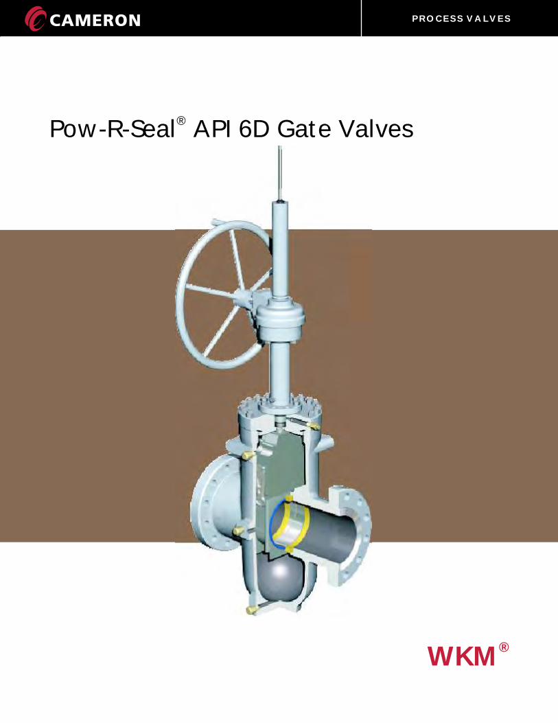
®Pow-R-Seal API 6D Gate Valves
P R O C E S S V A L V E S

P R O C E S S V A L V E S
CT-WKM-POWRSEAL/GATE02/07 NP-3M 1®
WKM
P R O C E S S V A L V E S
WKM Pow-R-Seal GATE VALVES
Design 2 & 3
Operating Principles 4 & 5
Features 6, 7 & 8
DIMENSIONAL DATA
Model M2 in. - 4 in. (50 mm - 100 mm) 9
Model E1C6 in. - 12 in. (150 mm - 300 mm) 10
Model E1C14 in. - 24 in. (350 mm - 600 mm) 11
GEAR SIZING
Model M2 in. - 4 in. (50 mm - 100 mm)
Model E1C6 in. -24 in. (150 mm - 300 mm) 12
Topworks Data 13 & 14
Flow Coefficients (C ) 15V
Flow Coefficients (K ) 16V
Partial Open Flow Characteristics (C or K ) 17V V
Pressure Temperature Ratings 18 & 19
Trim Chart 20 & 21
Applications (Pictures) 22 & 23
TRADEMARK INFORMATION 24
TERMS AND CONDITIONS OF SALE 25
TABLE OF CONTENTS
P R O C E S S V A L V E S
WKM POW-R-SEAL API 6D THROUGH-CONDUIT GATE VALVES
2
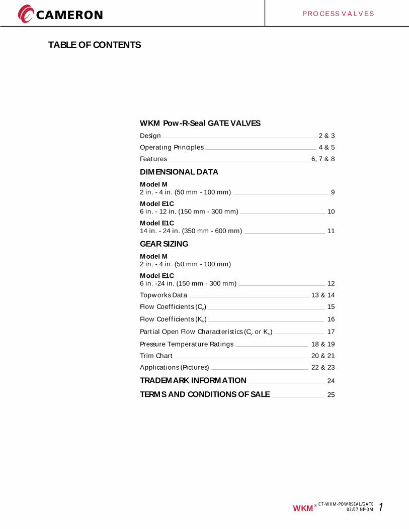
• Protection of seat faces. Seat faces are outside the flow stream and in full contact with the gate, in both fully open and fully closed positions. Seat life is thus greatly extended.
• Smooth, continuous conduit for flow. Destructive turbulence is eliminated. In a full-bore valve, pressure drop through the valve is no greater than that through an equal length of equal-diameter pipe.
• Block and bleed capability. The Pow-R-Seal valve in closed position forms a tight mechanical seal on both seats simultaneously, which allows the body cavity to be bled.
For specific applications, please consult factory.
TIGHT MECHANICAL SEALThe Pow-R-Seal’s parallel expanding gate design provides a tight mechanical seal, upstream and downstream simultaneously, which is normally unaffected by pressure variations or vibration. (See Operation, following page.) In the valve illustrated, for service at temperatures from -20°F to +300°F (-29°C to +148°C), the seal is both TFE-to-metal and metal-to-metal.*
*For service at high temperature, see pages 8-9.
The WKM Pow-R-Seal valve’s through-conduit design provides these specific advantages resulting in reliable performance and long life:
6 in. - 12 in. (150 mm - 300 mm)Pow-R-Seal Valve
Full-bore through-conduitdesign eliminates turbulence.Pressure drop is no greater than through an equal length of pipe.
Seat faces are protected from flow, as upstream and downstream seats are both in full contact with gate in either fully open or fully closed position. Seats and gate have Stellite #6 providing a metal-to-metal seal.
Gate centralizerprovides positivecontrol for improved operation
Parallel expandinggate (gate and segment)
Seat skirts
CT-WKM-POWRSEAL/GATE02/07 NP-3M
®WKM
Bonnet
P R O C E S S V A L V E S
3
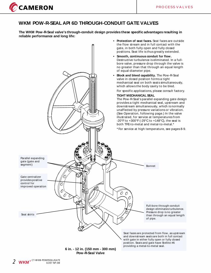
WKM POW-R-SEAL API 6D THROUGH-CONDUIT GATE VALVESPow-R-Seal valve for High-Temperature service Up to 1000°F (538°C)
This Pow-R-Seal valve can handle fluids, gases, steam and hot water at temperatures up to 1000°F (538°C). The valve has the following features which put it in a class by itself for such critical service:
• Metal-to-metal, mechanical seal - no elastomers.Valve does not depend on line pressure to shut off. Seal is normally unaffected by pressure surges, vibration, or heat.
• Adjustable outside packing gland - proved best for extremely hot service.
• Metal-to-metal bonnet seal - the boltedbonnet design used on 6 inch and larger valves and bolted bonnet design used on 4 inch and smaller valves provide metal-to-metal, tight bonnet seals in high temperature applications.
• Protected seat faces, a function of the valve’s through-conduit design. Seat faces are outside the flow stream and in full contact with the gate, whether the valve is open or closed. Seats last longer and shut off tight.
• Smooth, continuous conduit for flow. No turbulence. In full bore valves, pressure drop is no greater than through an equal length of equal diameter pipe.
• Rising stem design - puts stem threads outside the critical heat area.
®WKM
Bonnet stud and nut
Gate centralizer
Parallel expanding gate(gate & segment)
Bonnet
Full-bore through-conduitdesign eliminates turbulence;pressure drop no more than through an equal length of pipe.
Seat skirts
Body
Adjustable outside packing gland - proved best for extremely hot service
Hardened stainless steel stem
CT-WKM-POWRSEAL/GATE02/07 NP-3M
Seat faces are protected from flow, as upstream and downstream seats are both in full contact with gate in either fully open or fully closed position. Seats and gate have Stellite #6 providing a metal-to-metal seal.
P R O C E S S V A L V E S
4
WKM POW-R-SEAL API 6D THROUGH-CONDUIT GATE VALVES
OPERATING PRINCIPLESThe Pow-R-Seal gate valve is a premium through conduit expanding gate valve. The parallel expanding gate design provides a tight mechanical seal which is normally unaffected by pressure variations. Each seat contains a plastic face seal. The seats are press fit into the body to affect a metal-to-metal body-seat seal. A non-metallic seat rear seal is also provided. All metal seats are available for special trims.
The full bore design has the same pressure drop as an equivalent length of pipe and allows passage of all types of scrapers (pigs).
The body center section is cast as a single piece to provide the necessary strength to resist pipeline bending moments.
The gate-segment assembly consists of Gate, Segment and Gate centralizer (two assemblies). The Gate-segment assembly is smaller than the space between the seats allowing free movement in the mid-travel position.
In the CLOSED position, the segment stops moving when it contacts the stop. Continued stem movement causes the gate to slide down the top angles, expanding the gate-segment outward against both seats. In the OPEN position, the segment stops moving when it contacts the stop.
Continued stem movement causes the gate to slide up the bottom angles, again expanding the gate-segment against both seats. Flow is isolated from the valve body. The gate centralizer allows the gate-segment to move freely and wedge only in the full open or full closed position.
Pow-R-Seal valves do not depend on lubrication for a seal in normal operation. However, lubricants/sealants can be injected to promote smooth operation*. Seat sealants can also be injected to affect a seal in an emergency should the seats become damaged due to foreign matter.
The stem is sealed by the SLS system. This seal is hydrocarbon fugitive emissions tested and has demonstrated seal-ability not to exceed 500 ppm leakage. It consists of a single Spring Loaded Lip seal, a lantern ring, a chevron ring and appropriate adapters. The Single
* Some high temperature valves do not have the seat injection feature.
Spring Loaded Lip seal contains four (4) separated sealing bands to promote reliability. The stem seal is completely contained in the bonnet. The stem is centered by bushings and the lower pedestal acts as a stem scraper. The seal works without a plastic injectable. In an emergency, plastic packing can be injected into the packing box to affect a temporary seal while the valve is under pressure.
The bonnet seal is made by a flat metal gasket in the 6 in. - 12 in. (150 mm - 300 mm) size range.Bonnet seals for sizes 14 in. - 24 in. (350 mm - 600 mm) are made with an O-ring seal. High temperature valves use a spiral wound metal gasket with a non-asbestos filler.
Pow-R-Seal valves are repairable in-line.
Pow-R-Seal gate valves meet the requirements of API 6D.
The valve stroke is established by manufacturing tolerances and cannot get out of adjustment.
Pow-R-Seal gate valves are available with hand wheel operators (some sizes), bevel gear operators, or less gearing (bare stem). Electric motor operators from a variety of suppliers can be offered.
Operator mounting is simplified as yoke tube upper flanges are in compliance with MSS-SP-102. Yoke tube flanges in compliance with ISO 5210 are available.
Pow-R-Seal gate valves are supplied with indicators as a standard for Handwheel and Bevel Gear Operated valves. Handwheel Operated valves have marks on the indicator rods which show when the valve is in the full open or closed position.
Pow-R-Seal gate valves are available with Lubrication/Packing/Drain extensions.
Pow-R-Seal gate valves are also available with Stem/Yoke tube extensions.
Pow-R-Seal gate valves are available with a variety of coatings including Coal Tar Epoxy for buried service, 2-3 part coating systems for marine environments, Inorganic Zinc Rich Epoxy, etc.
®WKM
CT-WKM-POWRSEAL/GATE02/07 NP-3M
P R O C E S S V A L V E S
5
WKM POW-R-SEAL API 6D THROUGH-CONDUIT GATE VALVES
OPERATION
WKM Pow-R-Seal is the ultimate choice for Full Port, Through Conduit, Positive Shut-Off gate valves.
60 years of Worldwide service in oil, gas, chemicals, water, slurry and multi-products has confirmed the Pow-R-Seal as the most trusted gate valve, where safety and reliability of sealing are critical.
The parallel expanding gate design provides a tight mechanical seal which is normally unaffected by vibrations or pressure variations.
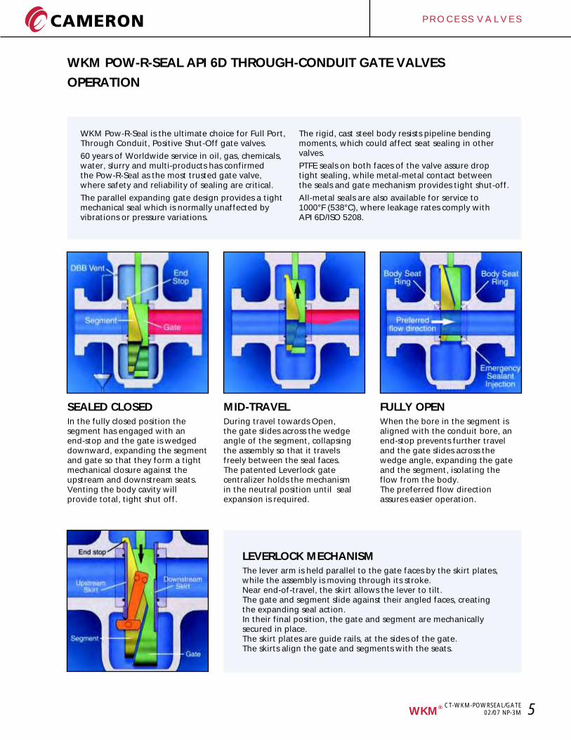
SEALED CLOSEDIn the fully closed position the segment has engaged with an end-stop and the gate is wedged downward, expanding the segment and gate so that they form a tight mechanical closure against the upstream and downstream seats. Venting the body cavity will provide total, tight shut off.
MID-TRAVELDuring travel towards Open, the gate slides across the wedge angle of the segment, collapsing the assembly so that it travels freely between the seal faces. The patented Leverlock gate centralizer holds the mechanism in the neutral position until seal expansion is required.
FULLY OPENWhen the bore in the segment is aligned with the conduit bore, an end-stop prevents further travel and the gate slides across the wedge angle, expanding the gate and the segment, isolating the flow from the body. The preferred flow direction assures easier operation.
LEVERLOCK MECHANISMThe lever arm is held parallel to the gate faces by the skirt plates, while the assembly is moving through its stroke. Near end-of-travel, the skirt allows the lever to tilt. The gate and segment slide against their angled faces, creating the expanding seal action. In their final position, the gate and segment are mechanically secured in place. The skirt plates are guide rails, at the sides of the gate. The skirts align the gate and segments with the seats.
The rigid, cast steel body resists pipeline bending moments, which could affect seat sealing in other valves.
PTFE seals on both faces of the valve assure drop tight sealing, while metal-metal contact between the seals and gate mechanism provides tight shut-off.
All-metal seals are also available for service to 1000°F (538°C), where leakage rates comply with API 6D/ISO 5208.
®WKM
CT-WKM-POWRSEAL/GATE02/07 NP-3M
P R O C E S S V A L V E S
6
WKM POW-R-SEAL API 6D THROUGH-CONDUIT GATE VALVES
FEATURES
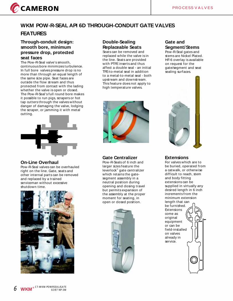
Through-conduit design:smooth bore, minimum pressure drop, protected seat facesThe Pow-R-Seal valve’s smooth, continuous bore minimizes turbulence. In full bore valves pressure drop is no more than through an equal length of the same size pipe. Seat faces are outside the flow stream and thus protected from contact with the lading whether the valve is open or closed.The Pow-R-Seal’s full round bore makes it possible to run pigs, scrapers or hot tap cutters through the valves without danger of damaging the valve, lodging the scraper, or jamming it with metal cutting.
Double-Sealing Replaceable SeatsSeats can be removed and replaced while the valve is in the line. Seats are provided with PTFE inserts and thus affect a double seal - an initial TFE-to-metal seal in addition to a metal-to-metal seal - both upstream and downstream.This feature does not apply to high temperature valves.
On-Line OverhaulPow-R-Seal valves can be overhauled right on the line. Gate, seats and other internal parts can be removed and replaced by a trained serviceman without excessive shutdown time.
Gate and Segment/StemsPow-R-Seal gates and stems are Nickel Plated. HF-6 overlay is available on request for the gate/segment and seat sealing surfaces.
Gate CentralizerPow-R-Seals of 6 inch and larger sizes feature the
®leverlock gate centralizer which retains the gate-segment assembly in a neutral position during opening and closing travel but permits expansion of the assembly at the proper moment for seating, in open or closed position.
ExtensionsFor valves which are to be buried, operated from a catwalk, or otherwise difficult to reach, stem and body fitting extensions can be supplied in virtually any desired length in 6 inch increments from the minimum extension length that canbe furnished.Extensionscome asoriginalequipmentor can befield-installedon valvesalready inservice.
®WKM
CT-WKM-POWRSEAL/GATE02/07 NP-3M
P R O C E S S V A L V E S
7
WKM POW-R-SEAL API 6D THROUGH-CONDUIT GATE VALVES
THERMAL RELIEF SYSTEM
ITEM PART QTY
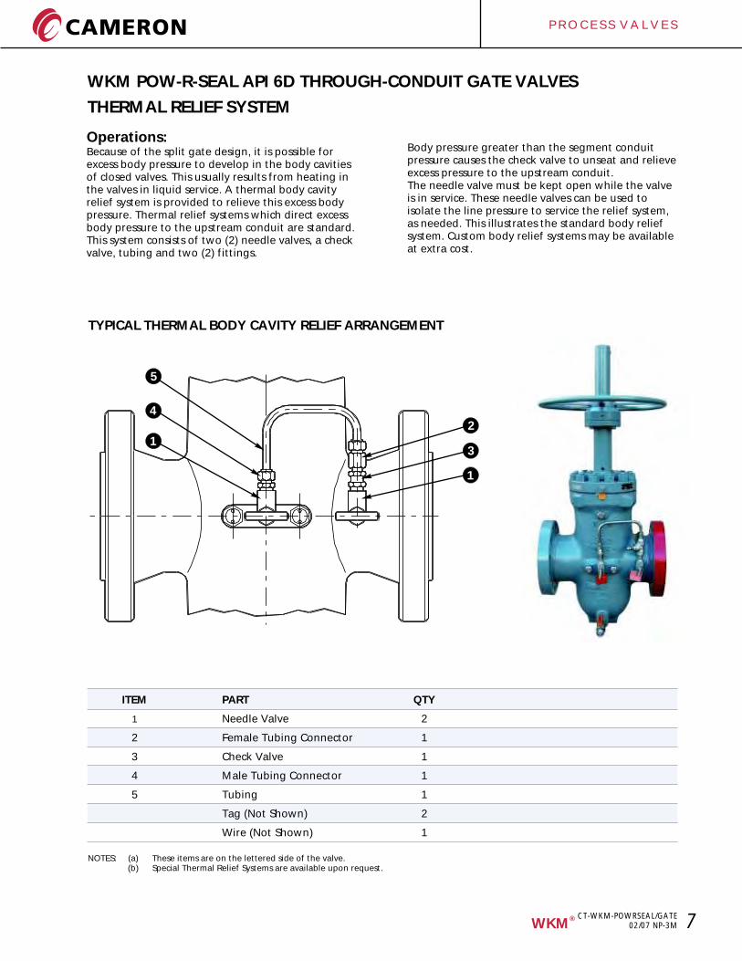
1 Needle Valve 2
2 Female Tubing Connector 1
3 Check Valve 1
4 Male Tubing Connector 1
5 Tubing 1
Tag (Not Shown) 2
Wire (Not Shown) 1
NOTES: (a) These items are on the lettered side of the valve.(b) Special Thermal Relief Systems are available upon request.
TYPICAL THERMAL BODY CAVITY RELIEF ARRANGEMENT
®WKM
Operations:Because of the split gate design, it is possible for excess body pressure to develop in the body cavities of closed valves. This usually results from heating in the valves in liquid service. A thermal body cavity relief system is provided to relieve this excess body pressure. Thermal relief systems which direct excess body pressure to the upstream conduit are standard. This system consists of two (2) needle valves, a check valve, tubing and two (2) fittings.
Body pressure greater than the segment conduit pressure causes the check valve to unseat and relieve excess pressure to the upstream conduit. The needle valve must be kept open while the valve is in service. These needle valves can be used to isolate the line pressure to service the relief system, as needed. This illustrates the standard body relief system. Custom body relief systems may be available at extra cost.
2
1
3
5
4
1
CT-WKM-POWRSEAL/GATE02/07 NP-3M
P R O C E S S V A L V E S
8
WKM POW-R-SEAL API 6D THROUGH-CONDUIT GATE VALVES
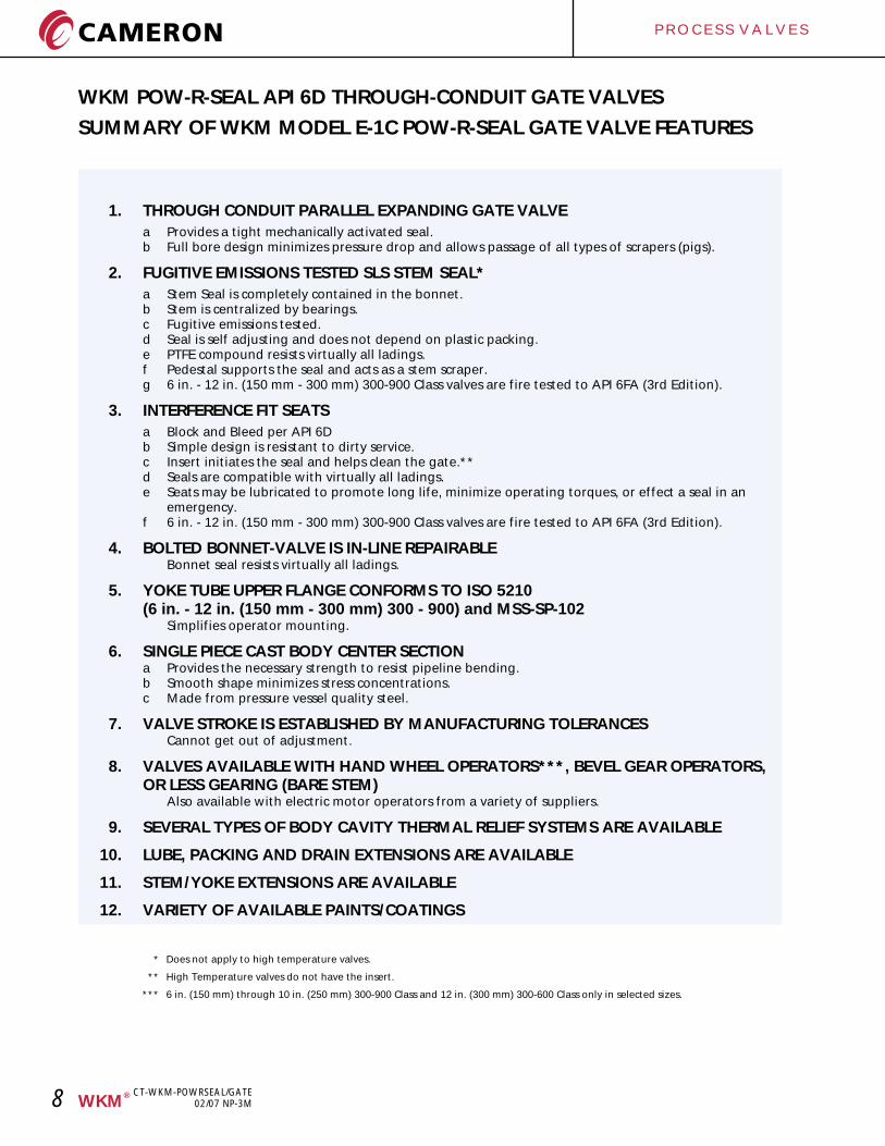
SUMMARY OF WKM MODEL E-1C POW-R-SEAL GATE VALVE FEATURES
1. THROUGH CONDUIT PARALLEL EXPANDING GATE VALVE
a Provides a tight mechanically activated seal.b Full bore design minimizes pressure drop and allows passage of all types of scrapers (pigs).
2. FUGITIVE EMISSIONS TESTED SLS STEM SEAL*
a Stem Seal is completely contained in the bonnet.b Stem is centralized by bearings.c Fugitive emissions tested.d Seal is self adjusting and does not depend on plastic packing.e PTFE compound resists virtually all ladings.f Pedestal supports the seal and acts as a stem scraper.g 6 in. - 12 in. (150 mm - 300 mm) 300-900 Class valves are fire tested to API 6FA (3rd Edition).
3. INTERFERENCE FIT SEATS
a Block and Bleed per API 6Db Simple design is resistant to dirty service.c Insert initiates the seal and helps clean the gate.**d Seals are compatible with virtually all ladings.e Seats may be lubricated to promote long life, minimize operating torques, or effect a seal in an
emergency.f 6 in. - 12 in. (150 mm - 300 mm) 300-900 Class valves are fire tested to API 6FA (3rd Edition).
4. BOLTED BONNET-VALVE IS IN-LINE REPAIRABLEBonnet seal resists virtually all ladings.
5. YOKE TUBE UPPER FLANGE CONFORMS TO ISO 5210 (6 in. - 12 in. (150 mm - 300 mm) 300 - 900) and MSS-SP-102
Simplifies operator mounting.
6. SINGLE PIECE CAST BODY CENTER SECTIONa Provides the necessary strength to resist pipeline bending.b Smooth shape minimizes stress concentrations.c Made from pressure vessel quality steel.
7. VALVE STROKE IS ESTABLISHED BY MANUFACTURING TOLERANCESCannot get out of adjustment.
8. VALVES AVAILABLE WITH HAND WHEEL OPERATORS***, BEVEL GEAR OPERATORS,OR LESS GEARING (BARE STEM)
Also available with electric motor operators from a variety of suppliers.
9. SEVERAL TYPES OF BODY CAVITY THERMAL RELIEF SYSTEMS ARE AVAILABLE
10. LUBE, PACKING AND DRAIN EXTENSIONS ARE AVAILABLE
11. STEM/YOKE EXTENSIONS ARE AVAILABLE
12. VARIETY OF AVAILABLE PAINTS/COATINGS
* Does not apply to high temperature valves.
** High Temperature valves do not have the insert.
*** 6 in. (150 mm) through 10 in. (250 mm) 300-900 Class and 12 in. (300 mm) 300-600 Class only in selected sizes.
®WKM
CT-WKM-POWRSEAL/GATE02/07 NP-3M
P R O C E S S V A L V E S
9®WKM
CT-WKM-POWRSEAL/GATE02/07 NP-3M
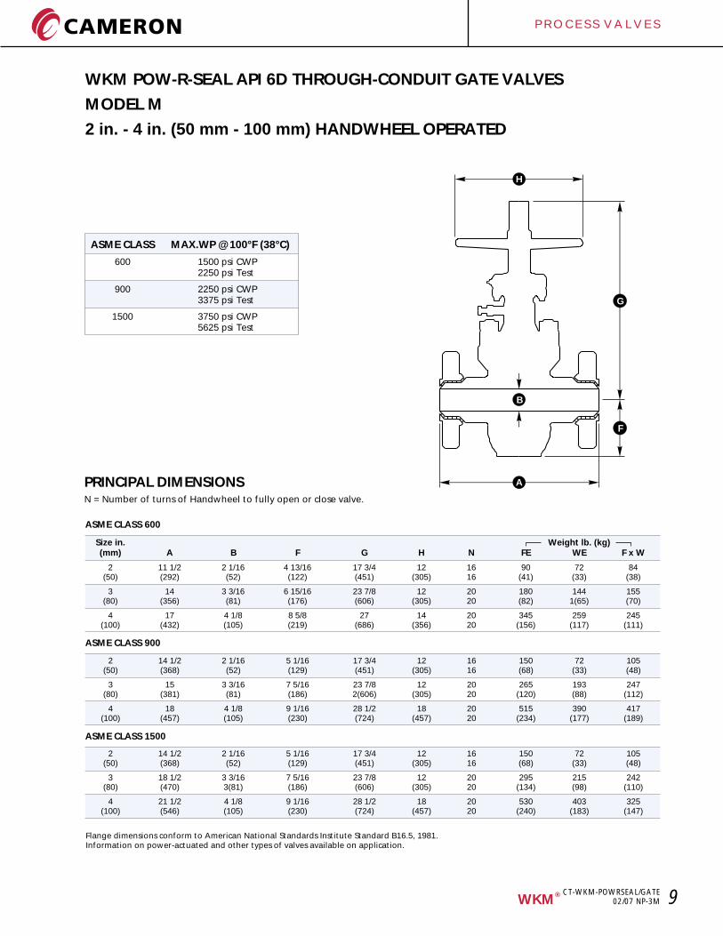
WKM POW-R-SEAL API 6D THROUGH-CONDUIT GATE VALVES
MODEL M
2 in. - 4 in. (50 mm - 100 mm) HANDWHEEL OPERATED
ASME CLASS MAX.WP @ 100°F (38°C)
600 1500 psi CWP2250 psi Test
900 2250 psi CWP3375 psi Test
1500 3750 psi CWP5625 psi Test
PRINCIPAL DIMENSIONSN = Number of turns of Handwheel to fully open or close valve.
Size in. (mm) A B F G H N FE WE F x W
2 11 1/2 2 1/16 4 13/16 17 3/4 12 16 90 72 84(50) (292) (52) (122) (451) (305) 16 (41) (33) (38)
3 14 3 3/16 6 15/16 23 7/8 12 20 180 144 155(80) (356) (81) (176) (606) (305) 20 (82) 1(65) (70)
4 17 4 1/8 8 5/8 27 14 20 345 259 245(100) (432) (105) (219) (686) (356) 20 (156) (117) (111)
Weight lb. (kg)
2 14 1/2 2 1/16 5 1/16 17 3/4 12 16 150 72 105(50) (368) (52) (129) (451) (305) 16 (68) (33) (48)
3 15 3 3/16 7 5/16 23 7/8 12 20 265 193 247(80) (381) (81) (186) 2(606) (305) 20 (120) (88) (112)
4 18 4 1/8 9 1/16 28 1/2 18 20 515 390 417(100) (457) (105) (230) (724) (457) 20 (234) (177) (189)
Flange dimensions conform to American National Standards Institute Standard B16.5, 1981.Information on power-actuated and other types of valves available on application.
ASME CLASS 600
ASME CLASS 900
ASME CLASS 1500
2 14 1/2 2 1/16 5 1/16 17 3/4 12 16 150 72 105(50) (368) (52) (129) (451) (305) 16 (68) (33) (48)
3 18 1/2 3 3/16 7 5/16 23 7/8 12 20 295 215 242(80) (470) 3(81) (186) (606) (305) 20 (134) (98) (110)
4 21 1/2 4 1/8 9 1/16 28 1/2 18 20 530 403 325(100) (546) (105) (230) (724) (457) 20 (240) (183) (147)
G
F
A
H
B
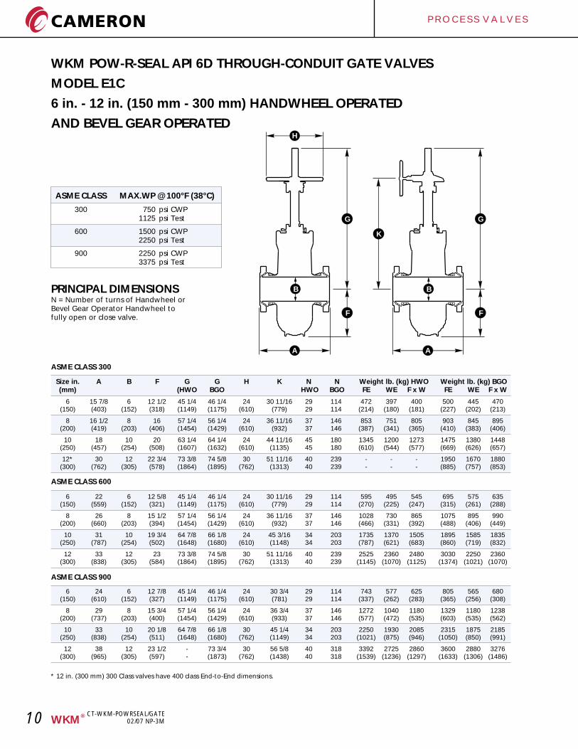
ASME CLASS MAX.WP @ 100°F (38°C)
300 750 psi CWP1125 psi Test
600 1500 psi CWP2250 psi Test
900 2250 psi CWP3375 psi Test
PRINCIPAL DIMENSIONSN = Number of turns of Handwheel orBevel Gear Operator Handwheel tofully open or close valve.
WKM POW-R-SEAL API 6D THROUGH-CONDUIT GATE VALVES
MODEL E1C
6 in. - 12 in. (150 mm - 300 mm) HANDWHEEL OPERATED
AND BEVEL GEAR OPERATED
Size in. N (mm) (HWO BGO HWO BGO FE WE F x W FE WE F x W
6 15 7/8 6 12 1/2 45 1/4 46 1/4 24 30 11/16 29 114 472 397 400 500 445 470(150) (403) (152) (318) (1149) (1175) (610) (779) 29 114 (214) (180) (181) (227) (202) (213)
8 16 1/2 8 16 57 1/4 56 1/4 24 36 11/16 37 146 853 751 805 903 845 895(200) (419) (203) (406) (1454) (1429) (610) (932) 37 146 (387) (341) (365) (410) (383) (406)
10 18 10 20 63 1/4 64 1/4 24 44 11/16 45 180 1345 1200 1273 1475 1380 1448(250) (457) (254) (508) (1607) (1632) (610) (1135) 45 180 (610) (544) (577) (669) (626) (657)
12* 30 12 22 3/4 73 3/8 74 5/8 30 51 11/16 40 239 - - - 1950 1670 1880(300) (762) (305) (578) (1864) (1895) (762) (1313) 40 239 - - - (885) (757) (853)
A B F G G H K N Weight lb. (kg) HWO Weight lb. (kg) BGO
ASME CLASS 300
6 22 6 12 5/8 45 1/4 46 1/4 24 30 11/16 29 114 595 495 545 695 575 635(150) (559) (152) (321) (1149) (1175) (610) (779) 29 114 (270) (225) (247) (315) (261) (288)
8 26 8 15 1/2 57 1/4 56 1/4 24 36 11/16 37 146 1028 730 865 1075 895 990(200) (660) (203) (394) (1454) (1429) (610) (932) 37 146 (466) (331) (392) (488) (406) (449)
10 31 10 19 3/4 64 7/8 66 1/8 24 45 3/16 34 203 1735 1370 1505 1895 1585 1835(250) (787) (254) (502) (1648) (1680) (610) (1148) 34 203 (787) (621) (683) (860) (719) (832)
12 33 12 23 73 3/8 74 5/8 30 51 11/16 40 239 2525 2360 2480 3030 2250 2360(300) (838) (305) (584) (1864) (1895) (762) (1313) 40 239 (1145) (1070) (1125) (1374) (1021) (1070)
ASME CLASS 600
6 24 6 12 7/8 45 1/4 46 1/4 24 30 3/4 29 114 743 577 625 805 565 680(150) (610) (152) (327) (1149) (1175) (610) (781) 29 114 (337) (262) (283) (365) (256) (308)
8 29 8 15 3/4 57 1/4 56 1/4 24 36 3/4 37 146 1272 1040 1180 1329 1180 1238(200) (737) (203) (400) (1454) (1429) (610) (933) 37 146 (577) (472) (535) (603) (535) (562)
10 33 10 20 1/8 64 7/8 66 1/8 30 45 1/4 34 203 2250 1930 2085 2315 1875 2185(250) (838) (254) (511) (1648) (1680) (762) (1149) 34 203 (1021) (875) (946) (1050) (850) (991)
12 38 12 23 1/2 - 73 3/4 30 56 5/8 40 318 3392 2725 2860 3600 2880 3276(300) (965) (305) (597) - (1873) (762) (1438) 40 318 (1539) (1236) (1297) (1633) (1306) (1486)
ASME CLASS 900
* 12 in. (300 mm) 300 Class valves have 400 class End-to-End dimensions.
G
F
A
K
BB
H
A
G
F
P R O C E S S V A L V E S
10 ®WKM
CT-WKM-POWRSEAL/GATE02/07 NP-3M
P R O C E S S V A L V E S
11®WKM
CT-WKM-POWRSEAL/GATE02/07 NP-3M
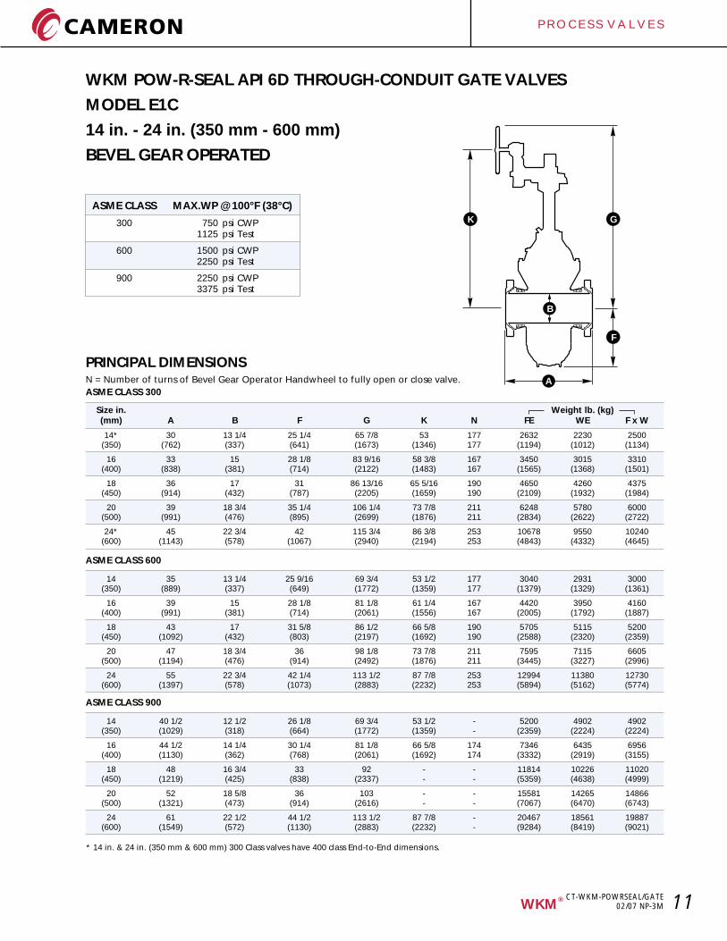
WKM POW-R-SEAL API 6D THROUGH-CONDUIT GATE VALVES
MODEL E1C
14 in. - 24 in. (350 mm - 600 mm)
BEVEL GEAR OPERATED
PRINCIPAL DIMENSIONSN = Number of turns of Bevel Gear Operator Handwheel to fully open or close valve.
Size in. (mm) A B F G K N FE WE F x W
14* 30 13 1/4 25 1/4 65 7/8 53 177 2632 2230 2500(350) (762) (337) (641) (1673) (1346) 177 (1194) (1012) (1134)
16 33 15 28 1/8 83 9/16 58 3/8 167 3450 3015 3310(400) (838) (381) (714) (2122) (1483) 167 (1565) (1368) (1501)
18 36 17 31 86 13/16 65 5/16 190 4650 4260 4375(450) (914) (432) (787) (2205) (1659) 190 (2109) (1932) (1984)
20 39 18 3/4 35 1/4 106 1/4 73 7/8 211 6248 5780 6000(500) (991) (476) (895) (2699) (1876) 211 (2834) (2622) (2722)
24* 45 22 3/4 42 115 3/4 86 3/8 253 10678 9550 10240(600) (1143) (578) (1067) (2940) (2194) 253 (4843) (4332) (4645)
Weight lb. (kg)
ASME CLASS 300
14 35 13 1/4 25 9/16 69 3/4 53 1/2 177 3040 2931 3000(350) (889) (337) (649) (1772) (1359) 177 (1379) (1329) (1361)
16 39 15 28 1/8 81 1/8 61 1/4 167 4420 3950 4160(400) (991) (381) (714) (2061) (1556) 167 (2005) (1792) (1887)
18 43 17 31 5/8 86 1/2 66 5/8 190 5705 5115 5200(450) (1092) (432) (803) (2197) (1692) 190 (2588) (2320) (2359)
20 47 18 3/4 36 98 1/8 73 7/8 211 7595 7115 6605(500) (1194) (476) (914) (2492) (1876) 211 (3445) (3227) (2996)
24 55 22 3/4 42 1/4 113 1/2 87 7/8 253 12994 11380 12730(600) (1397) (578) (1073) (2883) (2232) 253 (5894) (5162) (5774)
ASME CLASS 600
14 40 1/2 12 1/2 26 1/8 69 3/4 53 1/2 - 5200 4902 4902(350) (1029) (318) (664) (1772) (1359) - (2359) (2224) (2224)
16 44 1/2 14 1/4 30 1/4 81 1/8 66 5/8 174 7346 6435 6956(400) (1130) (362) (768) (2061) (1692) 174 (3332) (2919) (3155)
18 48 16 3/4 33 92 - - 11814 10226 11020(450) (1219) (425) (838) (2337) - - (5359) (4638) (4999)
20 52 18 5/8 36 103 - - 15581 14265 14866(500) (1321) (473) (914) (2616) - - (7067) (6470) (6743)
24 61 22 1/2 44 1/2 113 1/2 87 7/8 - 20467 18561 19887(600) (1549) (572) (1130) (2883) (2232) - (9284) (8419) (9021)
ASME CLASS 900
ASME CLASS MAX.WP @ 100°F (38°C)
300 750 psi CWP1125 psi Test
600 1500 psi CWP2250 psi Test
900 2250 psi CWP3375 psi Test
* 14 in. & 24 in. (350 mm & 600 mm) 300 Class valves have 400 class End-to-End dimensions.
G
F
A
K
B
P R O C E S S V A L V E S
12 ®WKM
CT-WKM-POWRSEAL/GATE02/07 NP-3M
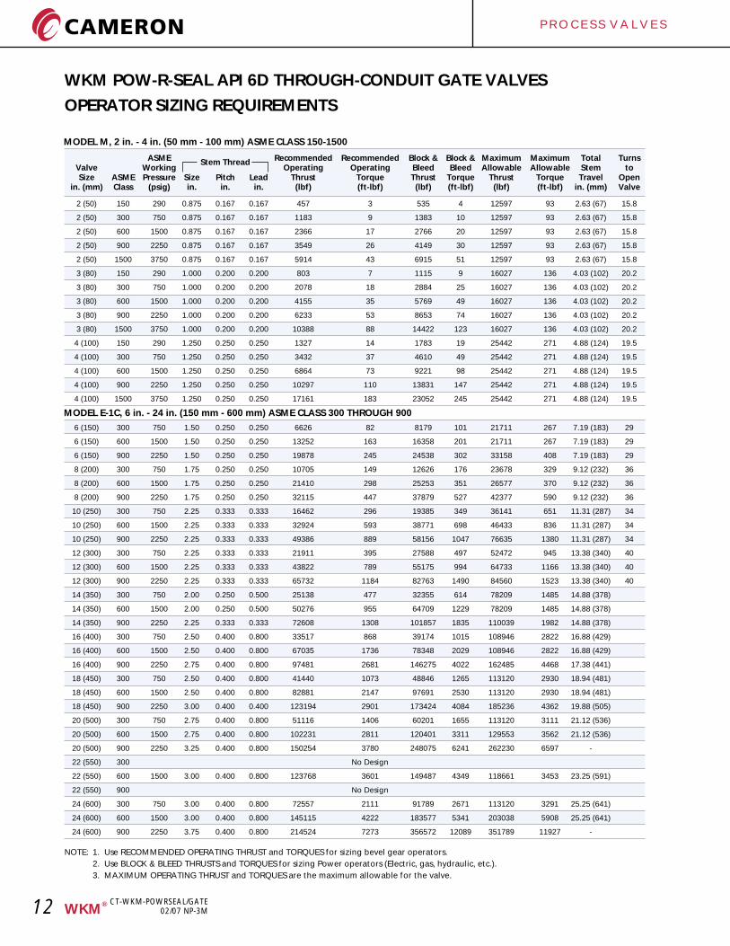
MODEL M, 2 in. - 4 in. (50 mm - 100 mm) ASME CLASS 150-1500
ASME Recommended Recommended Block & Block & Maximum Maximum Total TurnsStem ThreadValve Working Operating Operating Bleed Bleed Allowable Allowable Stem toSize ASME Pressure Size Pitch Lead Thrust Torque Thrust Torque Thrust Torque Travel Open
in. (mm) Class (psig) in. in. in. (lbf) (ft-lbf) (lbf) (ft-lbf) (lbf) (ft-lbf) in. (mm) Valve
2 (50) 150 290 0.875 0.167 0.167 457 3 535 4 12597 93 2.63 (67) 15.8
2 (50) 300 750 0.875 0.167 0.167 1183 9 1383 10 12597 93 2.63 (67) 15.8
2 (50) 600 1500 0.875 0.167 0.167 2366 17 2766 20 12597 93 2.63 (67) 15.8
2 (50) 900 2250 0.875 0.167 0.167 3549 26 4149 30 12597 93 2.63 (67) 15.8
2 (50) 1500 3750 0.875 0.167 0.167 5914 43 6915 51 12597 93 2.63 (67) 15.8
3 (80) 150 290 1.000 0.200 0.200 803 7 1115 9 16027 136 4.03 (102) 20.2
3 (80) 300 750 1.000 0.200 0.200 2078 18 2884 25 16027 136 4.03 (102) 20.2
3 (80) 600 1500 1.000 0.200 0.200 4155 35 5769 49 16027 136 4.03 (102) 20.2
3 (80) 900 2250 1.000 0.200 0.200 6233 53 8653 74 16027 136 4.03 (102) 20.2
3 (80) 1500 3750 1.000 0.200 0.200 10388 88 14422 123 16027 136 4.03 (102) 20.2
4 (100) 150 290 1.250 0.250 0.250 1327 14 1783 19 25442 271 4.88 (124) 19.5
4 (100) 300 750 1.250 0.250 0.250 3432 37 4610 49 25442 271 4.88 (124) 19.5
4 (100) 600 1500 1.250 0.250 0.250 6864 73 9221 98 25442 271 4.88 (124) 19.5
4 (100) 900 2250 1.250 0.250 0.250 10297 110 13831 147 25442 271 4.88 (124) 19.5
4 (100) 1500 3750 1.250 0.250 0.250 17161 183 23052 245 25442 271 4.88 (124) 19.5
6 (150) 300 750 1.50 0.250 0.250 6626 82 8179 101 21711 267 7.19 (183) 29
6 (150) 600 1500 1.50 0.250 0.250 13252 163 16358 201 21711 267 7.19 (183) 29
6 (150) 900 2250 1.50 0.250 0.250 19878 245 24538 302 33158 408 7.19 (183) 29
8 (200) 300 750 1.75 0.250 0.250 10705 149 12626 176 23678 329 9.12 (232) 36
8 (200) 600 1500 1.75 0.250 0.250 21410 298 25253 351 26577 370 9.12 (232) 36
8 (200) 900 2250 1.75 0.250 0.250 32115 447 37879 527 42377 590 9.12 (232) 36
10 (250) 300 750 2.25 0.333 0.333 16462 296 19385 349 36141 651 11.31 (287) 34
10 (250) 600 1500 2.25 0.333 0.333 32924 593 38771 698 46433 836 11.31 (287) 34
10 (250) 900 2250 2.25 0.333 0.333 49386 889 58156 1047 76635 1380 11.31 (287) 34
12 (300) 300 750 2.25 0.333 0.333 21911 395 27588 497 52472 945 13.38 (340) 40
12 (300) 600 1500 2.25 0.333 0.333 43822 789 55175 994 64733 1166 13.38 (340) 40
12 (300) 900 2250 2.25 0.333 0.333 65732 1184 82763 1490 84560 1523 13.38 (340) 40
14 (350) 300 750 2.00 0.250 0.500 25138 477 32355 614 78209 1485 14.88 (378)
14 (350) 600 1500 2.00 0.250 0.500 50276 955 64709 1229 78209 1485 14.88 (378)
14 (350) 900 2250 2.25 0.333 0.333 72608 1308 101857 1835 110039 1982 14.88 (378)
16 (400) 300 750 2.50 0.400 0.800 33517 868 39174 1015 108946 2822 16.88 (429)
16 (400) 600 1500 2.50 0.400 0.800 67035 1736 78348 2029 108946 2822 16.88 (429)
16 (400) 900 2250 2.75 0.400 0.800 97481 2681 146275 4022 162485 4468 17.38 (441)
18 (450) 300 750 2.50 0.400 0.800 41440 1073 48846 1265 113120 2930 18.94 (481)
18 (450) 600 1500 2.50 0.400 0.800 82881 2147 97691 2530 113120 2930 18.94 (481)
18 (450) 900 2250 3.00 0.400 0.400 123194 2901 173424 4084 185236 4362 19.88 (505)
20 (500) 300 750 2.75 0.400 0.800 51116 1406 60201 1655 113120 3111 21.12 (536)
20 (500) 600 1500 2.75 0.400 0.800 102231 2811 120401 3311 129553 3562 21.12 (536)
20 (500) 900 2250 3.25 0.400 0.800 150254 3780 248075 6241 262230 6597 -
22 (550) 300 No Design
22 (550) 600 1500 3.00 0.400 0.800 123768 3601 149487 4349 118661 3453 23.25 (591)
22 (550) 900 No Design
24 (600) 300 750 3.00 0.400 0.800 72557 2111 91789 2671 113120 3291 25.25 (641)
24 (600) 600 1500 3.00 0.400 0.800 145115 4222 183577 5341 203038 5908 25.25 (641)
24 (600) 900 2250 3.75 0.400 0.800 214524 7273 356572 12089 351789 11927 -
NOTE: 1. Use RECOMMENDED OPERATING THRUST and TORQUES for sizing bevel gear operators.
2. Use BLOCK & BLEED THRUSTS and TORQUES for sizing Power operators (Electric, gas, hydraulic, etc.).
3. MAXIMUM OPERATING THRUST and TORQUES are the maximum allowable for the valve.
WKM POW-R-SEAL API 6D THROUGH-CONDUIT GATE VALVES
OPERATOR SIZING REQUIREMENTS
MODEL E-1C, 6 in. - 24 in. (150 mm - 600 mm) ASME CLASS 300 THROUGH 900
P R O C E S S V A L V E S
13®WKM
CT-WKM-POWRSEAL/GATE02/07 NP-3M
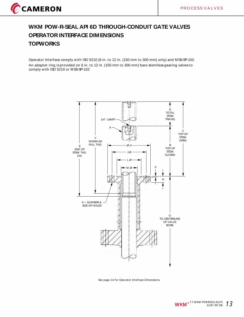
WKM POW-R-SEAL API 6D THROUGH-CONDUIT GATE VALVES
OPERATOR INTERFACE DIMENSIONS
TOPWORKS
Operator Interface comply with ISO 5210 (6 in. to 12 in. (150 mm to 300 mm) only) and MSS-SP-102.
An adapter ring is provided on 6 in. to 12 in. (150 mm to 300 mm) bare stem/less gearing valves to comply with ISO 5210 or MSS-SP-102
1/4”-18NPT
A
FMINIMUMFULL THD.
EEND OF
STEM THD.DIA
DTOTALSTEM
TRAVEL
Ø H
J Ø
L Ø
M Ø P
CTOP OFSTEMOPEN
BTOP OFSTEM
CLOSED
N
K = NUMBER &SIZE OF HOLES
GTO CENTERLINE
OF VALVEBORE
See page 14 for Operator Interface Dimensions.
P R O C E S S V A L V E S
14 ®WKM
CT-WKM-POWRSEAL/GATE02/07 NP-3M
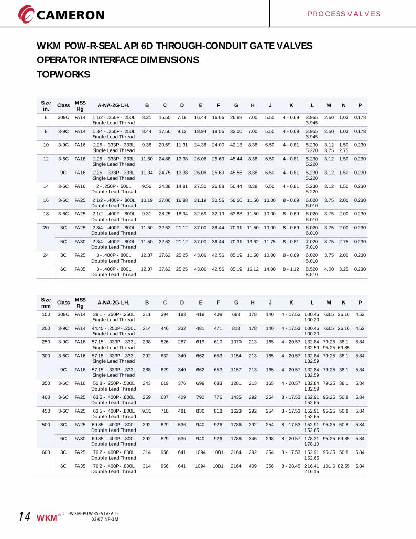
Size MSSClass A-NA-2G-L.H. B C D E F G H J K L M N Pin. Flg
6 309C FA14 1 1/2 - .250P - .250L 8.31 15.50 7.19 16.44 16.06 26.88 7.00 5.50 4 - 0.69 3.955 2.50 1.03 0.178Single Lead Thread 3.945
8 3-9C FA14 1 3/4 - .250P - .250L 8.44 17.56 9.12 18.94 18.56 32.00 7.00 5.50 4 - 0.69 3.955 2.50 1.03 0.178Single Lead Thread 3.945
10 3-9C FA16 2.25 - .333P - .333L 9.38 20.69 11.31 24.38 24.00 42.13 8.38 6.50 4 - 0.81 5.230 3.12 1.50 0.230Single Lead Thread 5.220 3.75 2.75
12 3-6C FA16 2.25 - .333P - .333L 11.50 24.88 13.38 26.06 25.69 45.44 8.38 6.50 4 - 0.81 5.230 3.12 1.50 0.230Single Lead Thread 5.220
9C FA16 2.25 - .333P - .333L 11.34 24.75 13.38 26.06 25.69 45.56 8.38 6.50 4 - 0.81 5.230 3.12 1.50 0.230Single Lead Thread 5.220
14 3-6C FA16 2 - .250P - .500L 9.56 24.38 14.81 27.50 26.88 50.44 8.38 6.50 4 - 0.81 5.230 3.12 1.50 0.230Double Lead Thread 5.220
16 3-6C FA25 2 1/2 - .400P - .800L 10.19 27.06 16.88 31.19 30.56 56.50 11.50 10.00 8 - 0.69 6.020 3.75 2.00 0.230Double Lead Thread 6.010
18 3-6C FA25 2 1/2 - .400P - .800L 9.31 28.25 18.94 32.69 32.19 63.88 11.50 10.00 8 - 0.69 6.020 3.75 2.00 0.230Double Lead Thread 6.010
20 3C FA25 2 3/4 - .400P - .800L 11.50 32.62 21.12 37.00 36.44 70.31 11.50 10.00 8 - 0.69 6.020 3.75 2.00 0.230Double Lead Thread 6.010
6C FA30 2 3/4 - .400P - .800L 11.50 32.62 21.12 37.00 36.44 70.31 13.62 11.75 8 - 0.81 7.020 3.75 2.75 0.230Double Lead Thread 7.010
24 3C FA25 3 - .400P - .800L 12.37 37.62 25.25 43.06 42.56 85.19 11.50 10.00 8 - 0.69 6.020 3.75 2.00 0.230Double Lead Thread 6.010
6C FA35 3 - .400P - .800L 12.37 37.62 25.25 43.06 42.56 85.19 16.12 14.00 8 - 1.12 8.520 4.00 3.25 0.230Double Lead Thread 8.510
Size MSSClass A-NA-2G-L.H. B C D E F G H J K L M N Pmm Flg
150 309C FA14 38.1 - .250P - .250L 211 394 183 418 408 683 178 140 4 - 17.53 100.46 63.5 26.16 4.52Single Lead Thread 100.20
200 3-9C FA14 44.45 - .250P - .250L 214 446 232 481 471 813 178 140 4 - 17.53 100.46 63.5 26.16 4.52Single Lead Thread 100.20
250 3-9C FA16 57.15 - .333P - .333L 238 526 287 619 610 1070 213 165 4 - 20.57 132.84 79.25 38.1 5.84Single Lead Thread 132.59 95.25 69.85
300 3-6C FA16 57.15 - .333P - .333L 292 632 340 662 653 1154 213 165 4 - 20.57 132.84 79.25 38.1 5.84Single Lead Thread 132.59
9C FA16 57.15 - .333P - .333L 288 629 340 662 653 1157 213 165 4 - 20.57 132.84 79.25 38.1 5.84Single Lead Thread 132.59
350 3-6C FA16 50.8 - .250P - .500L 243 619 376 699 683 1281 213 165 4 - 20.57 132.84 79.25 38.1 5.84Double Lead Thread 132.59
400 3-6C FA25 63.5 - .400P - .800L 259 687 429 792 776 1435 292 254 8 - 17.53 152.91 95.25 50.8 5.84Double Lead Thread 152.65
450 3-6C FA25 63.5 - .400P - .800L 9.31 718 481 830 818 1623 292 254 8 - 17.53 152.91 95.25 50.8 5.84Double Lead Thread 152.65
500 3C FA25 69.85 - .400P - .800L 292 829 536 940 926 1786 292 254 8 - 17.53 152.91 95.25 50.8 5.84Double Lead Thread 152.65
6C FA30 69.85 - .400P - .800L 292 829 536 940 926 1786 346 298 8 - 20.57 178.31 95.25 69.85 5.84Double Lead Thread 178.10
600 3C FA25 76.2 - .400P - .800L 314 956 641 1094 1081 2164 292 254 8 - 17.53 152.91 95.25 50.8 5.84Double Lead Thread 152.65
6C FA35 76.2 - .400P - .800L 314 956 641 1094 1081 2164 409 356 8 - 28.45 216.41 101.6 82.55 5.84Double Lead Thread 216.15
WKM POW-R-SEAL API 6D THROUGH-CONDUIT GATE VALVES
OPERATOR INTERFACE DIMENSIONS
TOPWORKS
P R O C E S S V A L V E S
15®WKM
CT-WKM-POWRSEAL/GATE02/07 NP-3M
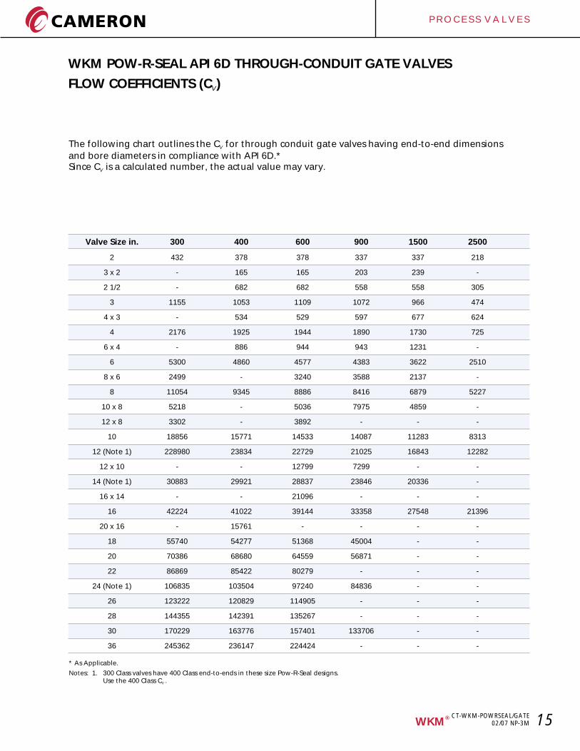
WKM POW-R-SEAL API 6D THROUGH-CONDUIT GATE VALVES
FLOW COEFFICIENTS (C )V
The following chart outlines the C for through conduit gate valves having end-to-end dimensions V
and bore diameters in compliance with API 6D.*Since C is a calculated number, the actual value may vary.V
Valve Size in. 300 400 600 900 1500 2500
2 432 378 378 337 337 218
3 x 2 - 165 165 203 239 -
2 1/2 - 682 682 558 558 305
3 1155 1053 1109 1072 966 474
4 x 3 - 534 529 597 677 624
4 2176 1925 1944 1890 1730 725
6 x 4 - 886 944 943 1231 -
6 5300 4860 4577 4383 3622 2510
8 x 6 2499 - 3240 3588 2137 -
8 11054 9345 8886 8416 6879 5227
10 x 8 5218 - 5036 7975 4859 -
12 x 8 3302 - 3892 - - -
10 18856 15771 14533 14087 11283 8313
12 (Note 1) 228980 23834 22729 21025 16843 12282
12 x 10 - - 12799 7299 - -
14 (Note 1) 30883 29921 28837 23846 20336 -
16 x 14 - - 21096 - - -
16 42224 41022 39144 33358 27548 21396
20 x 16 - 15761 - - - -
18 55740 54277 51368 45004 - -
20 70386 68680 64559 56871 - -
22 86869 85422 80279 - - -
24 (Note 1) 106835 103504 97240 84836 - -
26 123222 120829 114905 - - -
28 144355 142391 135267 - - -
30 170229 163776 157401 133706 - -
36 245362 236147 224424 - - -
* As Applicable.
Notes: 1. 300 Class valves have 400 Class end-to-ends in these size Pow-R-Seal designs.Use the 400 Class C .V
P R O C E S S V A L V E S
16 ®WKM
CT-WKM-POWRSEAL/GATE02/07 NP-3M
WKM POW-R-SEAL API 6D THROUGH-CONDUIT GATE VALVES
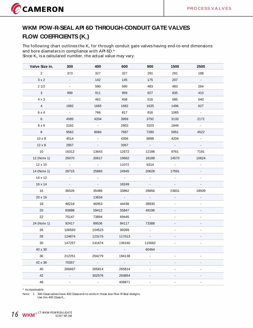
FLOW COEFFICIENTS (K )V
The following chart outlines the K for through conduit gate valves having end-to-end dimensions V
and bore diameters in compliance with API 6D.*Since K is a calculated number, the actual value may vary.V
Valve Size in. 300 400 600 900 1500 2500
2 373 327 327 291 291 188
3 x 2 - 142 145 175 207 -
2 1/2 - 590 590 483 483 264
3 999 911 959 927 835 410
4 x 3 - 462 458 516 585 540
4 1882 1665 1682 1635 1496 627
6 x 4 - 766 817 816 1065 -
6 4585 4204 3959 3792 3133 2172
8 x 6 2162 - 2803 3103 1849 -
8 9562 8084 7687 7280 5951 4522
10 x 8 4514 - 4356 6898 4204 -
12 x 8 2857 - 3367 - - -
10 16312 13643 12572 12186 9761 7191
12 (Note 1) 25070 20617 19662 18188 14570 10624
12 x 10 - - 11072 6314 - -
14 (Note 1) 26715 25883 24945 20628 17591 -
14 x 12 - - - - - -
16 x 14 - - 18249 - - -
16 36526 35486 33862 28856 23831 18509
20 x 16 - 13634 - - - -
18 48218 46953 44436 38930 - -
20 60888 59412 55847 49196 - -
22 75147 73894 69445 - - -
24 (Note 1) 92417 89536 84117 73388 - -
26 106593 104523 99399 - - -
28 124874 123175 117013 - - -
30 147257 141674 136160 115662 - -
40 x 30 - - - 60464
36 212251 204279 194138 - - -
42 x 36 70357 - - - - -
40 266697 265814 265814 - - -
42 - 302576 293854 - - -
48 - - 408871 - - -
* As Applicable.
Note: 1. 300 Class valves have 400 Class end-to-ends in these size Pow-R-Seal designs.Use the 400 Class K .V
P R O C E S S V A L V E S
17®WKM
CT-WKM-POWRSEAL/GATE02/07 NP-3M
WKM POW-R-SEAL API 6D THROUGH-CONDUIT GATE VALVES
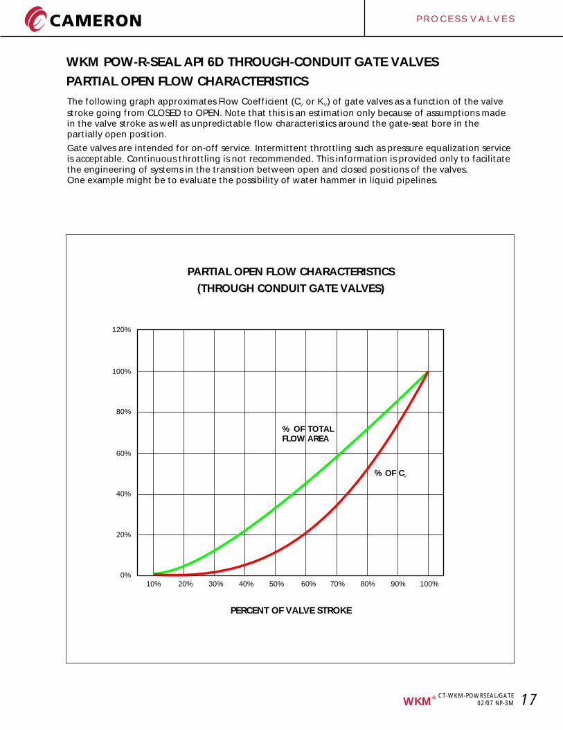
PARTIAL OPEN FLOW CHARACTERISTICS
The following graph approximates Flow Coefficient (C or K ) of gate valves as a function of the valve V V
stroke going from CLOSED to OPEN. Note that this is an estimation only because of assumptions made in the valve stroke as well as unpredictable flow characteristics around the gate-seat bore in the partially open position.
Gate valves are intended for on-off service. Intermittent throttling such as pressure equalization service is acceptable. Continuous throttling is not recommended. This information is provided only to facilitate the engineering of systems in the transition between open and closed positions of the valves. One example might be to evaluate the possibility of water hammer in liquid pipelines.
120%
100%
80%
60%
40%
20%
0%10% 20% 30% 40% 50% 60% 70% 80% 90% 100%
% OF TOTALFLOW AREA
% OF CV
PARTIAL OPEN FLOW CHARACTERISTICS
(THROUGH CONDUIT GATE VALVES)
PERCENT OF VALVE STROKE
P R O C E S S V A L V E S
18 ®WKM
WKM POW-R-SEAL API 6D THROUGH-CONDUIT GATE VALVES
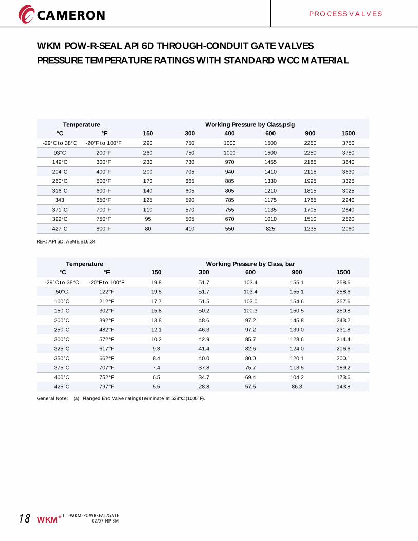
PRESSURE TEMPERATURE RATINGS WITH STANDARD WCC MATERIAL
Working Pressure by Class, bar
°C °F 150 300 600 900 1500
-29°C to 38°C -20°F to 100°F 19.8 51.7 103.4 155.1 258.6
50°C 122°F 19.5 51.7 103.4 155.1 258.6
100°C 212°F 17.7 51.5 103.0 154.6 257.6
150°C 302°F 15.8 50.2 100.3 150.5 250.8
200°C 392°F 13.8 48.6 97.2 145.8 243.2
250°C 482°F 12.1 46.3 97.2 139.0 231.8
300°C 572°F 10.2 42.9 85.7 128.6 214.4
325°C 617°F 9.3 41.4 82.6 124.0 206.6
350°C 662°F 8.4 40.0 80.0 120.1 200.1
375°C 707°F 7.4 37.8 75.7 113.5 189.2
400°C 752°F 6.5 34.7 69.4 104.2 173.6
425°C 797°F 5.5 28.8 57.5 86.3 143.8
Temperature
General Note: (a) Flanged End Valve ratings terminate at 538°C (1000°F).
Working Pressure by Class,psig
°C °F 150 300 400 600 900 1500
-29°C to 38°C -20°F to 100°F 290 750 1000 1500 2250 3750
93°C 200°F 260 750 1000 1500 2250 3750
149°C 300°F 230 730 970 1455 2185 3640
204°C 400°F 200 705 940 1410 2115 3530
260°C 500°F 170 665 885 1330 1995 3325
316°C 600°F 140 605 805 1210 1815 3025
343 650°F 125 590 785 1175 1765 2940
371°C 700°F 110 570 755 1135 1705 2840
399°C 750°F 95 505 670 1010 1510 2520
427°C 800°F 80 410 550 825 1235 2060
Temperature
REF.: API 6D, ASME B16.34
CT-WKM-POWRSEAL/GATE02/07 NP-3M
P R O C E S S V A L V E S
19®WKM
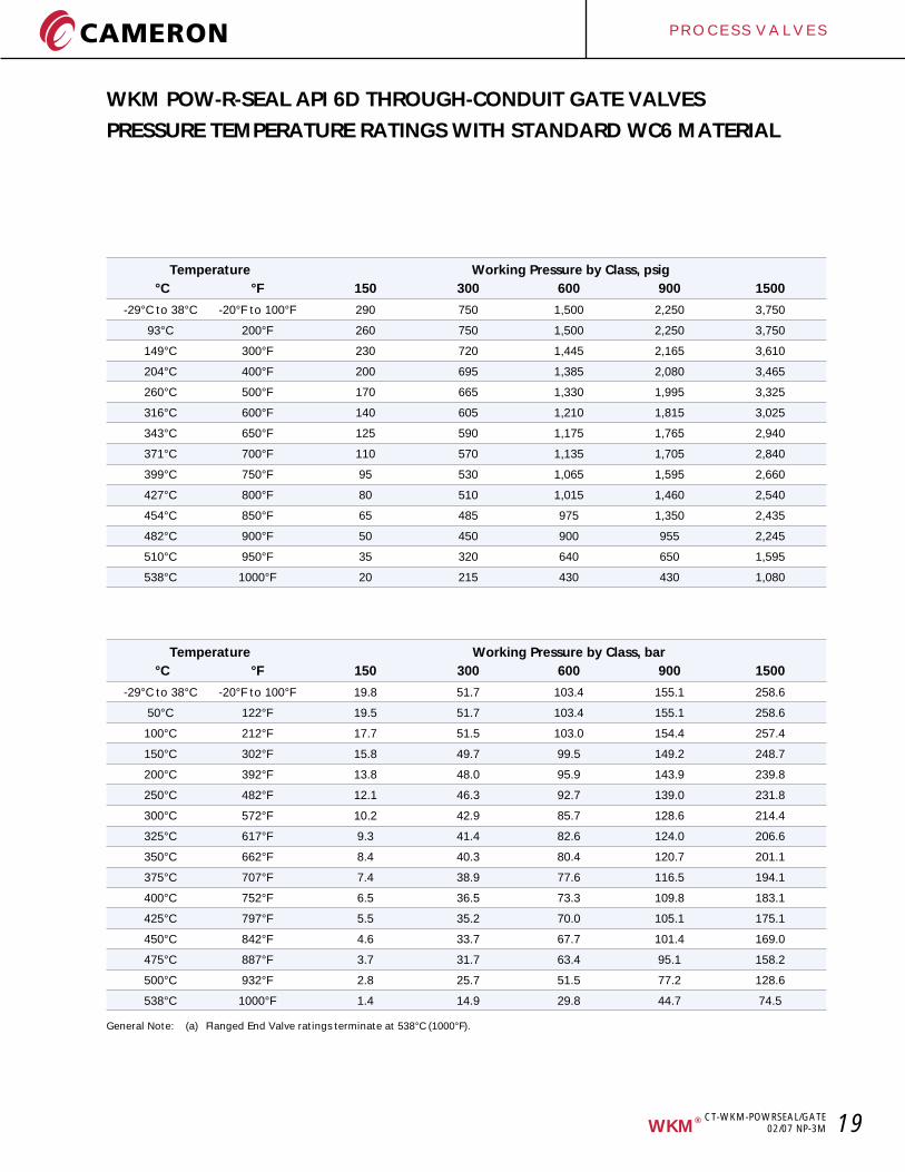
WKM POW-R-SEAL API 6D THROUGH-CONDUIT GATE VALVES
PRESSURE TEMPERATURE RATINGS WITH STANDARD WC6 MATERIAL
Working Pressure by Class, bar
°C °F 150 300 600 900 1500
-29°C to 38°C -20°F to 100°F 19.8 51.7 103.4 155.1 258.6
50°C 122°F 19.5 51.7 103.4 155.1 258.6
100°C 212°F 17.7 51.5 103.0 154.4 257.4
150°C 302°F 15.8 49.7 99.5 149.2 248.7
200°C 392°F 13.8 48.0 95.9 143.9 239.8
250°C 482°F 12.1 46.3 92.7 139.0 231.8
300°C 572°F 10.2 42.9 85.7 128.6 214.4
325°C 617°F 9.3 41.4 82.6 124.0 206.6
350°C 662°F 8.4 40.3 80.4 120.7 201.1
375°C 707°F 7.4 38.9 77.6 116.5 194.1
400°C 752°F 6.5 36.5 73.3 109.8 183.1
425°C 797°F 5.5 35.2 70.0 105.1 175.1
450°C 842°F 4.6 33.7 67.7 101.4 169.0
475°C 887°F 3.7 31.7 63.4 95.1 158.2
500°C 932°F 2.8 25.7 51.5 77.2 128.6
538°C 1000°F 1.4 14.9 29.8 44.7 74.5
Temperature
General Note: (a) Flanged End Valve ratings terminate at 538°C .(1000°F)
Working Pressure by Class, psig
°C °F 150 300 600 900 1500
-29°C to 38°C -20°F to 100°F 290 750 1,500 2,250 3,750
93°C 200°F 260 750 1,500 2,250 3,750
149°C 300°F 230 720 1,445 2,165 3,610
204°C 400°F 200 695 1,385 2,080 3,465
260°C 500°F 170 665 1,330 1,995 3,325
316°C 600°F 140 605 1,210 1,815 3,025
343°C 650°F 125 590 1,175 1,765 2,940
371°C 700°F 110 570 1,135 1,705 2,840
399°C 750°F 95 530 1,065 1,595 2,660
427°C 800°F 80 510 1,015 1,460 2,540
454°C 850°F 65 485 975 1,350 2,435
482°C 900°F 50 450 900 955 2,245
510°C 950°F 35 320 640 650 1,595
538°C 1000°F 20 215 430 430 1,080
Temperature
CT-WKM-POWRSEAL/GATE02/07 NP-3M
P R O C E S S V A L V E S
20 ®WKM
WKM POW-R-SEAL API 6D THROUGH-CONDUIT GATE VALVES
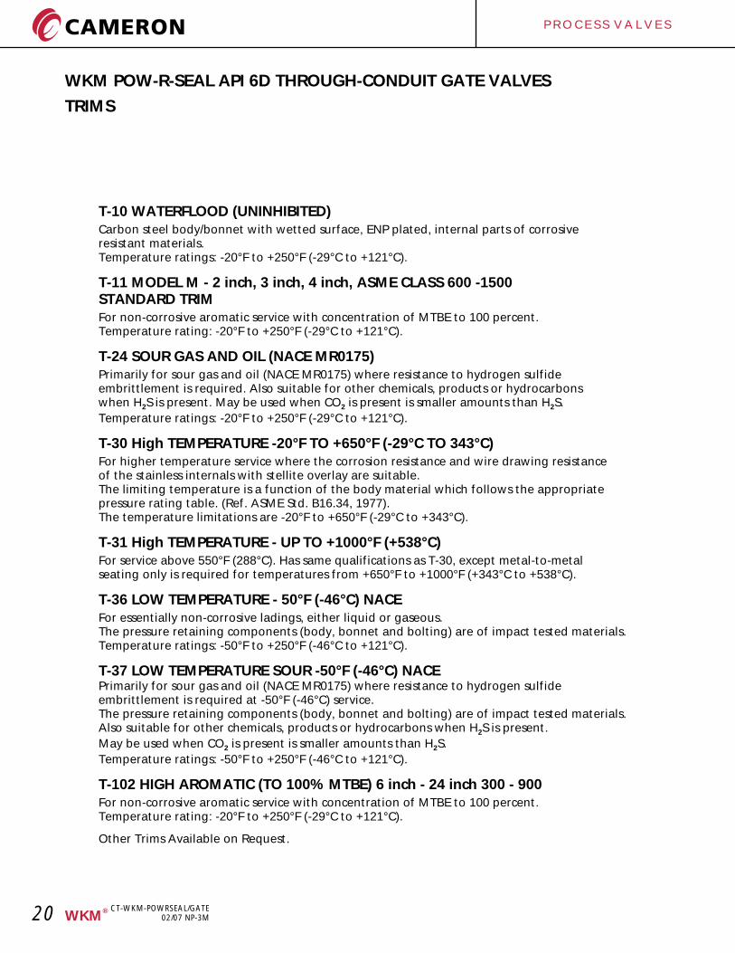
TRIMS
T-10 WATERFLOOD (UNINHIBITED)Carbon steel body/bonnet with wetted surface, ENP plated, internal parts of corrosive resistant materials. Temperature ratings: -20°F to +250°F (-29°C to +121°C).
T-11 MODEL M - 2 inch, 3 inch, 4 inch, ASME CLASS 600 -1500 STANDARD TRIMFor non-corrosive aromatic service with concentration of MTBE to 100 percent.Temperature rating: -20°F to +250°F (-29°C to +121°C).
T-24 SOUR GAS AND OIL (NACE MR0175)Primarily for sour gas and oil (NACE MR0175) where resistance to hydrogen sulfide embrittlement is required. Also suitable for other chemicals, products or hydrocarbons when H S is present. May be used when CO is present is smaller amounts than H S. 2 2 2
Temperature ratings: -20°F to +250°F (-29°C to +121°C).
T-30 High TEMPERATURE -20°F TO +650°F (-29°C TO 343°C)For higher temperature service where the corrosion resistance and wire drawing resistance of the stainless internals with stellite overlay are suitable. The limiting temperature is a function of the body material which follows the appropriate pressure rating table. (Ref. ASME Std. B16.34, 1977). The temperature limitations are -20°F to +650°F (-29°C to +343°C).
T-31 High TEMPERATURE - UP TO +1000°F (+538°C)For service above 550°F (288°C). Has same qualifications as T-30, except metal-to-metal seating only is required for temperatures from +650°F to +1000°F (+343°C to +538°C).
T-36 LOW TEMPERATURE - 50°F (-46°C) NACEFor essentially non-corrosive ladings, either liquid or gaseous.The pressure retaining components (body, bonnet and bolting) are of impact tested materials.Temperature ratings: -50°F to +250°F (-46°C to +121°C).
T-37 LOW TEMPERATURE SOUR -50°F (-46°C) NACEPrimarily for sour gas and oil (NACE MR0175) where resistance to hydrogen sulfide embrittlement is required at -50°F (-46°C) service.The pressure retaining components (body, bonnet and bolting) are of impact tested materials.Also suitable for other chemicals, products or hydrocarbons when H S is present. 2
May be used when CO is present is smaller amounts than H S. 2 2
Temperature ratings: -50°F to +250°F (-46°C to +121°C).
T-102 HIGH AROMATIC (TO 100% MTBE) 6 inch - 24 inch 300 - 900For non-corrosive aromatic service with concentration of MTBE to 100 percent.Temperature rating: -20°F to +250°F (-29°C to +121°C).
Other Trims Available on Request.
CT-WKM-POWRSEAL/GATE02/07 NP-3M
P R O C E S S V A L V E S
21®WKM
WKM POW-R-SEAL API 6D THROUGH-CONDUIT GATE VALVES
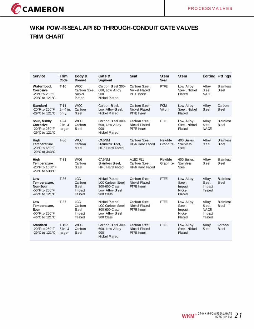
TRIM CHART
Service Trim Body & Gate & Seat Stem Stem Bolting FittingsCode Bonnet Segment Seal
Waterflood, T-10 WCC Carbon Steel 300- Carbon Steel, PTFE Low Alloy Alloy StainlessCorrosive Carbon Steel, 600, Low Alloy Nickel Plated Steel, Nickel Steel Steel-20°F to 250°F Nickel 900 PTFE Insert Plated NACE-29°C to 121°C Plated Nickel Plated
Standard T-11 WCC Carbon Steel, Carbon Steel, FKM Low Alloy Alloy Carbon-20°F to 250°F 2 - 4 in. Carbon Low Alloy Steel, Nickel Plated Viton Steel, Nickel Steel Steel-29°C to 121°C only Steel Nickel Plated PTFE Insert Plated
Sour, Mildly T-24 WCC Carbon Steel 300- Carbon Steel, PTFE Low Alloy Alloy StainlessCorrosive 2 in. & Carbon 600, Low Alloy Nickel Plated Steel, Nickel Steel Steel-20°F to 250°F larger Steel 900 PTFE Insert Plated NACE-29°C to 121°C Nickel Plated
High T-30 WCC CA6NM Carbon Steel, Flexible 400 Series Alloy StainlessTemperature Carbon Stainless Steel, HF-6 Hard Faced Graphite Stainless Steel Steel-20°F to 650°F Steel HF-6 Hard Faced Steel-29°C to 343°C
High T-31 WC6 CA6NM A182 F11 Flexible 400 Series Alloy StainlessTemperature Carbon Stainless Steel, Carbon Steel, Graphite Stainless Steel Steel-20°F to 1000°F Steel HF-6 Hard Faced HF-6 Hard Faced Steel-29°C to 538°C
Low T-36 LCC Nickel Plated Carbon Steel, PTFE Low Alloy Alloy StainlessTemperature, Carbon LCC Carbon Steel Nickel Plated Steel, Steel, SteelNon-Sour Steel 300-600 Class PTFE Insert Impact Impact-50°F to 250°F Impact Low Alloy Steel Nickel Tested-46°C to 121°C Tested 900 Class Plated
Low T-37 LCC Nickel Plated Carbon Steel, PTFE Low Alloy Alloy StainlessTemperature, Carbon LCC Carbon Steel Nickel Plated Steel, Steel, SteelSour Steel 300-600 Class PTFE Insert Impact NACE,-50°F to 250°F Impact Low Alloy Steel Nickel Impact-46°C to 121°C Tested 900 Class Plated Tested
Standard T-102 WCC Carbon Steel 300- Carbon Steel, PTFE Low Alloy Alloy Carbon-20°F to 250°F 6 in. & Carbon 600, Low Alloy Nickel Plated Steel, Nickel Steel Steel-29°C to 121°C larger Steel 900 PTFE Insert Plated
Nickel Plated
CT-WKM-POWRSEAL/GATE02/07 NP-3M
P R O C E S S V A L V E S
22 ®WKM
WKM POW-R-SEAL API 6D THROUGH-CONDUIT GATE VALVES
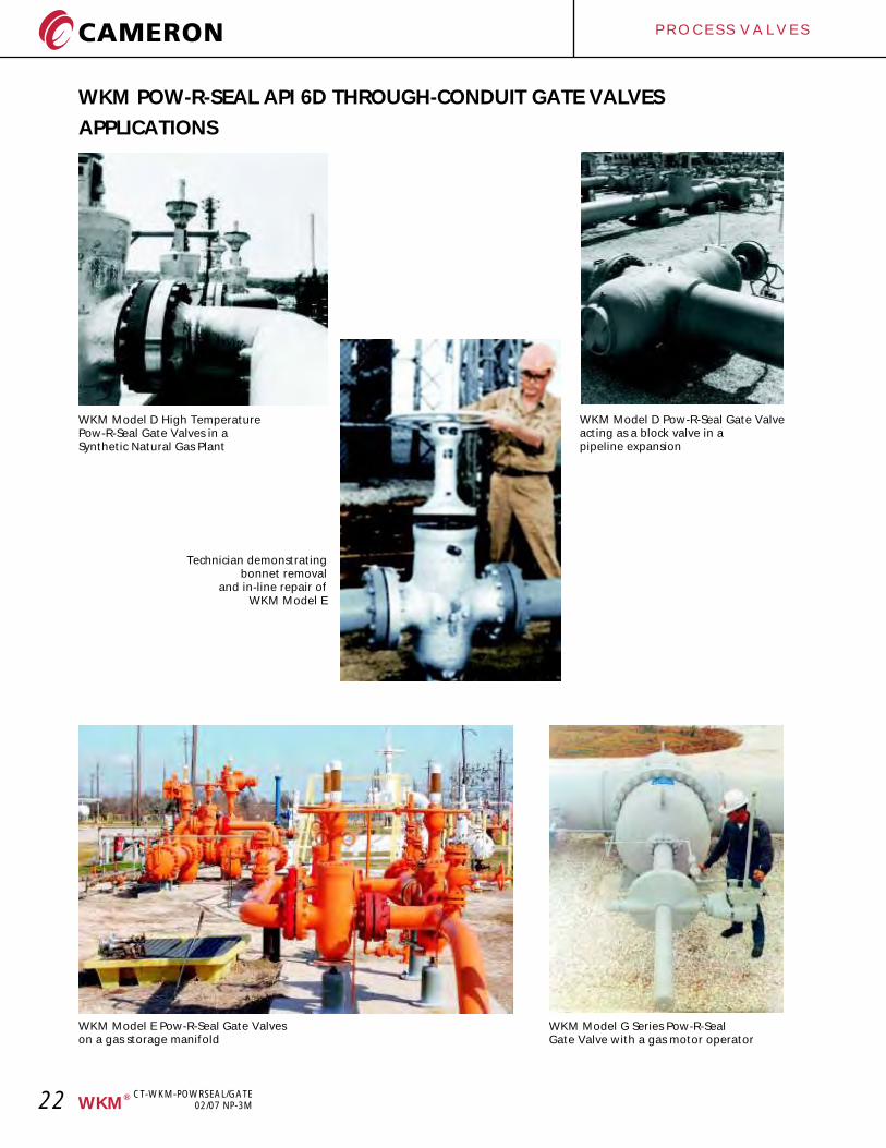
APPLICATIONS
WKM Model D High TemperaturePow-R-Seal Gate Valves in aSynthetic Natural Gas Plant
WKM Model D Pow-R-Seal Gate Valveacting as a block valve in apipeline expansion
Technician demonstratingbonnet removal
and in-line repair ofWKM Model E
WKM Model E Pow-R-Seal Gate Valveson a gas storage manifold
WKM Model G Series Pow-R-SealGate Valve with a gas motor operator
CT-WKM-POWRSEAL/GATE02/07 NP-3M
P R O C E S S V A L V E S
23®WKM
WKM POW-R-SEAL API 6D THROUGH-CONDUIT GATE VALVES
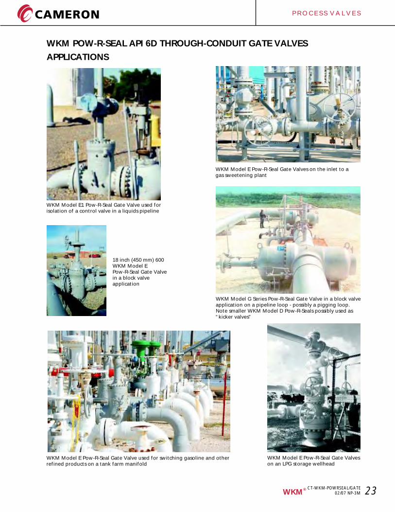
APPLICATIONS
WKM Model E1 Pow-R-Seal Gate Valve used forisolation of a control valve in a liquids pipeline
WKM Model E Pow-R-Seal Gate Valve used for switching gasoline and otherrefined products on a tank farm manifold
WKM Model E Pow-R-Seal Gate Valveson an LPG storage wellhead
WKM Model G Series Pow-R-Seal Gate Valve in a block valveapplication on a pipeline loop - possibly a pigging loop.Note smaller WKM Model D Pow-R-Seals possibly used as“kicker valves”
WKM Model E Pow-R-Seal Gate Valves on the inlet to agas sweetening plant
18 inch (450 mm) 600WKM Model EPow-R-Seal Gate Valvein a block valveapplication
CT-WKM-POWRSEAL/GATE02/07 NP-3M
24
P R O C E S S V A L V E S
TRADEMARK INFORMATION
®WKM is a registered trademark which is owned by Cameron.
This document contains references to registered trademarks or product designations, which are not owned by Cameron.
Trademark OwnerInconel INCO Nickel Sales, Inc.
Monel INCO Alloys International, Inc.
Stellite Stoody Deloro Stellite, Inc.
Teflon E.I. DuPont De Nemours & Company
Viton E.I. DuPont De Nemours & Company
®WKM
CT-WKM-POWRSEAL/GATE02/07 NP-3M
®WKM
CT-WKM-POWRSEAL/GATE02/07 NP-3M 25
1. CONTRACT ACCEPTANCE:Any written or oral purchase order received from Buyer by Seller shall be construed as a written acceptance of Seller’s offer to sell and shall be filled in accordance with the terms and conditions of sale set forth herein. SELLER’S ACCEPTANCE OF THIS ORDER IS EXPRESSLY CONDITIONED ON BUYER’S ASSENT TO THE TERMS CONTAINED HEREIN. The terms and conditions of Seller’s proposal (if any) and acknowledgement shall prevail over any conflicting or different terms in Buyer’s order unless Buyer notifies Seller in writing of its objections thereto within fifteen (15) days from receipt of Seller’s acknowledgement. Buyer’s standard terms of purchase will not be considered a counteroffer to Seller’s terms and conditions of sale. The failure of Seller to object to any provision in conflict herewith whether contained on Buyer’s purchase order or otherwise shall not be construed as a waiver of the provisions hereof nor as an acceptance thereof.2. QUOTATIONS AND PRICES:Any product, service capability or manufacturing capability which may be available at the time a quotation is made is subject to prior sale. Prices quoted are subject to change without notice. The price in effect at the time of shipment including any escalation formula will apply, unless a valid quotation or written agreement to the contrary exists between Buyer and Seller. All prices shown are in U.S. dollars and are F.O.B. Seller’s shipping point. Seller reserves the right to place a service charge on past due accounts at the highest rate permitted by law. Any documentation pertaining to traceability requirements for raw materials or products or documentation required for any routine or special processes must be identified by the Buyer at the time of quotation (if any) or at the time of order placement.3. TAXES:Any tax or other charge imposed by law on the sale or production of goods or the performance of services shall be paid by the Buyer, unless the law specifically provides that such payment must be made by Seller, in which case Buyer shall reimburse Seller for such payment as part of the purchase price. Custom duties, consular fees, insurance charges and other comparable charges will be borne by Buyer.4. SHIPPING SCHEDULE AND DELIVERY:Shipment schedules are given as accurately as conditions permit and every effort will be made to make shipments as scheduled. Seller will not be responsible for deviations in meeting shipping schedules nor for any losses or damages to Buyer (or any third party) occasioned by deviations in the shipping schedule, whether due to Acts of God, orders bearing priority ratings established pursuant to law, differences with workmen, local labor shortages, fire, flood, shortages or failure of raw materials, supplies, fuel, power or transportation, breakdown of equipment or any other causes beyond Seller’s reasonable control, whether of similar or dissimilar nature than those enumerated. Seller shall have additional time within which to perform as may be reasonably necessary under the circumstances and shall have the right to apportion its production among its customers in such a manner as it may consider to be equitable. Seller reserves the right to furnish commercially equivalent or better substitutes for materials or to subcontract the Buyer’s order or portions thereof as Seller deems necessary. In no event shall Seller be liable for any consequential damages resulting from failure or delay in shipment. If Buyer requires drawings, procedures, standards or similar material for approval, shipping schedules will be calculated from the time such approvals are received by Seller, since shipping schedules are based on Seller having all required information and a firm order from Buyer which is enterable into production. Any hold points, witness points or the need for inspection by Buyer’s representatives must be identified by Buyer at the time of quotation (if any) and/or order placement in order that the effect on the prices or shipping schedules (if any) can be taken into account. Additional inspection or testing required by Buyer which affects normal production sequence will be considered as extending the shipping dates accordingly.5. TERMS OF PAYMENT:Terms of payment are 30 days from date of invoice unless otherwise stated in the quotation or Seller’s order acknowledgment.6. CANCELLATIONS AND RETURNS:Purchase orders once placed by Buyer and accepted by Seller can be canceled only with Seller’s written consent and upon terms which will save Seller from loss. No products may be returned for credit or adjustment without written permission from Seller’s office authorized to issue such permission.7. WARRANTIES:All products of Seller’s manufacture except for its Orbit product are warranted against defects of material and workmanship for a period of twelve (12) months from the date of installation or eighteen (18) months from date of shipment, whichever period first expires while its Orbit product is warranted for thirty six (36) months from date of shipment, when all such products are used in the service and within the pressure range for which they were manufactured. In the case of products or parts not wholly of Seller’s manufacture, Seller’s liability shall be limited to the extent of its recovery from the manufacturer of such products or parts under its liability to Seller. Any repair work performed by Seller is warranted for one year from completion of such repairs and applies only to work performed. If, within these specified periods, Seller receives notice from Buyer of any alleged defect in or nonconformance of any product or repair and if in the Seller’s sole judgment the product or repair does not conform or is found to be defective in material or workmanship, then, Buyer shall, at Seller’s request, return the part or product F.O.B. to Seller’s designated plant or service location. Seller has no liability for removal or reinstallation of products or equipment. Seller, at its option and expense, shall repair or replace the defective part or product, or repay to Buyer the full price paid by Buyer for such defective part, repair or product. Any repayment of purchase price shall be without interest. Seller’s warranty liability, including defects caused by Seller’s negligence, shall be limited to such repair, replacement or refund, and shall not include claims for labor costs, expenses of Buyer resulting from such defects, recovery under general tort law or strict liability or for damages resulting from delays, loss of use, or other direct, indirect, incidental or consequential damages of any kind. Seller will not be responsible for failures of products which have been in any way tampered with or altered by anyone other than an authorized representative of Seller, failures due to lack of compliance with recommended maintenance procedures or products which have been repaired or altered in such a way (in Seller’s judgment) as to affect the products adversely. THIS WARRANTY IS EXPRESSLY IN LIEU OF ALL OTHER WARRANTIES, EXPRESS, STATUTORY OR IMPLIED, INCLUDING THE WARRANTY OF MERCHANTABILITY AND FITNESS FOR PARTICULAR PURPOSE WHICH EXCEED THE FOREGOING WARRANTY.8.ENGINEERING AND SERVICE:Upon request, Seller will provide engineering and/or technical information regarding its products and their uses and, if feasible, will provide personnel to assist Buyer in effecting field installations and/or field service. Any such information, service or assistance so provided, whether with or without charge, shall be advisory only9. LABOR STANDARDS:Seller hereby certifies that these products were produced in accordance with all applicable requirements of Section 6, 7 and 12 of the Fair Labor Standards Act as amended and of regulations and orders of the United States Department of Labor issued under Section 14 thereof.10. INSPECTION:Unless otherwise agreed in writing, final inspection and acceptance of products must be made at Seller’s plant or other shipping or receiving point designated by Seller and shall be conclusive except as regards latent defects. Buyer’s representatives may inspect at the Seller’s plant or shipping point during working hours prior to shipment in such manner as will not interfere with operations.11. DELIVERY AND ACCEPTANCE:Delivery shall be in accordance with the requirements in the Purchase Contract, provided, in the event Buyer is unable to accept delivery upon completion of the manufacture of the Goods in accordance with such requirements, Buyer agrees that (i) title and risk of ownership shall pass to Buyer on date of Seller’s invoice, and (ii) Buyer will make payments within thirty days after date of such invoice. Seller shall retain custodial risk of loss until delivery is made in accordance with such requirements.12. EXPORT COMPLIANCE:The Buyer shall provide the Seller with relevant end-use, end-user and country of end-use information with respect to the goods, services, software or technology to be supplied hereunder (collectively, “Items”). Based on and in reliance on such information, the Seller will supply such Items in compliance with applicable trade and customs laws including that of the United States of America. The Seller cautionsand the Buyer acknowledges that any change in end-use, end-user or country of end-use (including ashipment between countries other than the U.S.) may be restricted or prohibited by applicable trade and
customs law, whether it be of the U.S. or other country. The Parties shall comply with all trade and customs laws (including U.S. Export Controls) except for any such laws which conflict with or are otherwise penalized under the laws of the U.S., which in the event of such conflict, Seller shall notify Buyer. The Buyer agrees in particular that it shall not use and shall not permit any third party to use such items in connection with the design, production, use, or storage of chemical, biological or nuclear weapons or missiles of any kind.13. TRANSPORTATION CHARGES, ALLOWANCES, CLAIMS:All prices are F.O.B. Seller’s plant or other designated shipping point. No freight is allowed unless stated in Seller’s quotation (if any) or in a written contract which may exist between Seller and Buyer at the time of shipment. If Seller’s quotation or a written contract states that all or a portion of freight is allowed, all prices are F.O.B. Seller’s plant or other designated shipping point, with most economical surface transportation allowed. If the quoted or contractual price includes transportation, Seller reserves the right to designate the common carrier and to ship in the manner it deems most economical. Added costs due to special routing requested by the Buyer are chargeable to the Buyer. Under no circumstances is any freight allowance which is absorbed by Seller to be deducted from the selling price. If the quoted price or contract includes transportation, no deduction will be made in lieu thereof whether Buyer accepts shipment at plant, warehouse, freight station, or otherwise supplies its own transportation. When sales are made from the Seller’s warehouse, Seller reserves the right to charge either actual or pro-rated freight from Seller’s principle point of manufacture to Seller’s warehouse. Buyer assumes risk of loss upon delivery to the carrier, regardless of who pays shipping costs. Seller endeavors to pack or prepare all shipments so that they will not break, rust or deteriorate in transit, but does not guarantee against such damage. Unless requested in writing by the Buyer, no shipments are insured by Seller against damage or loss in transit. Seller will place insurance as nearly as possible in accordance with Buyer’s written instructions but in such case Seller acts only as agent between the insurance company and the Buyer and assumes no liability whatsoever. Any claims for shipping loss, breakage or damage (obvious or concealed) are Buyer’s responsibility and should be made to the carrier. All claims regarding shortages must be made within thirty (30) days from receipt of shipment and must be accompanied by the packing list(s) covering the shipment.14. INDEMNIFICATION AND LIMITATION OF LIABILITY:A. INDEMNIFICATION:“Buyer Group” means: Buyer, its parent (if any), subsidiaries, affiliates, co-owners, co-venturers, partners and any entity with whom Buyer has an economic interest with respect to the Work including Buyer’s customer and its and their respective employees, personnel, directors, officers, borrowed servants, representatives, agents, contractors and subcontractors (respectively and of any tier or level and who are not included within the Seller Group), “Seller Group” means: Seller, its parent (if any), subsidiaries, affiliates, co-owners and its and their respective employees, personnel, directors, officers, borrowed servants, representatives, agents, contractors and subcontractors (respectively and of any tier or level and who are not included within the Buyer Group), “Negligence” means: sole, joint or concurrent, active, passive, gross or willful misconduct.(1) Seller shall release, defend, save, indemnify (collectively “Indemnify”) and hold Buyer Group harmless from and against all claims, demands, losses, damages and causes of action of whatever kind or nature (collectively “Claims”), for loss of or damage to the property of the members of the Seller Group even if such Claims arise from or attributable to the Negligence of the members of Buyer Group.(2) Seller shall Indemnify and hold Buyer Group harmless from and against all Claims for the death(s) of or personal injury(ies) to members of the Seller Group even if such Claims arise from or attributable to the Negligence of the members of Buyer Group.(3) Buyer shall Indemnify and hold Seller Group harmless from and against all Claims for loss of or damage to the property (including the Work) of the members of the Buyer Group even if such Claims arise from or attributable to the Negligence of the members of Seller Group.(4) Buyer shall Indemnify and hold Seller Group harmless from and against all Claims for the death(s) of or personal injury(ies) to members of the Buyer Group even if such Claims arise from or attributable to the Negligence of the members of Seller Group.(5) Buyer (on its own behalf and on behalf of Buyer Group) and Seller (on its own behalf and on behalf of Seller Group) shall Indemnify and hold each other harmless from and against any and all Claims asserted against them by or on behalf of any third party for the death(s) of or personal injury (ies) to such a third party, as well as loss (es) of or damage(s) to the property of such a third party. A third party is a person or entity not included in Buyer Group or Seller Group. It is agreed by Buyer and Seller that their respective duty of indemnity to each other with respect to Claims asserted against them by a third party pursuant to this Article 14 (A) (5) shall be limited to their respective degree of Negligence.(6) Notwithstanding any other provision contained in this Agreement, Buyer shall Indemnify and hold the members of Seller Group harmless from and against all Claims (including clean-up costs and loss (es) of oil, gas or hydrocarbons) arising from pollution, contamination, dumping or spilling of any substance and even if arising out of or attributable to the Negligence of the members of the Seller Group.B. INDEMNITY FOR CONSEQUENTIAL DAMAGES:UNDER NO CIRCUMSTANCES SHALL SELLER BE LIABLE FOR ANY SPECIAL, CONSEQUENTIAL,INCIDENTAL, EXEMPLARY OR PUNITIVE DAMAGES (collectively “CONSEQUENTIAL”), AS DEFINED BY THE LAWS GOVERNING THIS PURCHASE ORDER, NOR FOR ANY LOSS OF ANTICIPATED PROFITS, LOSS OF BUSINESS OPPORTUNITY, LOSS OF USE OF EQUIPMENT OR OF ANY INSTALLATION, SYSTEM OR FACILITY INTO WHICH SELLER’S EQUIPMENT MAY BE LOCATED OR AT WHICH MEMBERS OF THE SELLER GROUP MAY BE PERFORMING WORK AND BUYER AGREES TO “INDEMNIFY” AND HOLD SELLER GROUP HARMLESS FROM AND AGAINST ANY “CLAIMS” FOR SUCH “CONSEQUENTIAL” DAMAGES EVEN IF ARISING OUT OF OR ATTRIBUTABLE TO THE “NEGLIGENCE” OF THE MEMBERS OF THE SELLER GROUP.C. LIMITATION OF LIABILITY:EXCEPT AS OTHERWISE EXPRESSLY LIMITED IN THIS AGREEMENT IT IS THE EXPRESS INTENTION OF THE PARTIES HERETO THAT ALL INDEMNITY OBLIGATIONS AND/OR LIABILITIES HEREBY ASSUMED BY THE PARTIES SHALL BE: (i) SUPPORTED BY INSURANCE; (ii) WITHOUT LIMIT; (iii) AND WITHOUT REGARD TO THE CAUSE OR CAUSES THEREOF, INCLUDING, BUT NOT LIMITED TO, PREEXISTING CONDITIONS (WHETHER SUCH CONDITIONS BE PATENT OR LATENT); THE UNSEAWORTHINESS OF ANY VESSEL OR VESSELS (WHETHER OR NOT PREEXISTING); THE UNAIRWORTHINESS OF ANY AIRCRAFT; BREACH OF REPRESENTATION OR WARRANTY (EXPRESS OR IMPLIED); BREACH OF CONTRACT; BREACH OF DUTY (STATUTORY, CONTRACTUAL, COMMON LAW OR OTHERWISE); STRICT LIABILITY; CONDITION OF RUIN OR DEFECTIVE PREMISES, EQUIPMENT, FACILITIES, OR APPURTENANCES OF ANY PARTY UNDER ANY CODE, LAW OR (WHETHER OR NOT SAID CONDITION IS PREEXISTING AND/OR LATENT, PATENT OR OTHERWISE); THE LOADING OR UNLOADING OF PERSONS OR CARGO; TORT; OR THE NEGLIGENCE OR FAULT OF ANY PARTY (AS DEFINED AT THE BEGINNING OF THIS ARTICLE 14; OR ANY OTHER THEORY OF LEGAL LIABILITY.Seller’s total responsibility for any claims, damages, losses or liability arising out of or related to its performance of this contract or the products or services covered hereunder shall not exceed the purchase price.15. MODIFICATION, RESCISSION & WAIVER:The terms herein may not be modified or rescinded nor any of its provisions waived unless such modification, rescission or waiver is in writing and signed by an authorized employee of Seller at its office in Houston, Texas. Failure of Seller to insist in any one or more instances upon the performance of any of the terms and conditions of the contract or the failure of Seller to exercise any of its rights hereunder shall not be construed as a waiver or relinquishment of any such term, condition, or right hereunder and shall not affect Seller’s right to insist upon strict performance and compliance with regard to any unexecuted portions of this contract or future performance of these terms and conditions.All orders must be accepted by an authorized employee of Seller. The rights and duties of the parties and construction and effect of all provisions hereof shall be governed by and construed according to the internal laws of the State of Texas. Any disputes which arise under this agreement shall be venued in the District Court of Harris County, Texas or in the Southern District of Texas.
CAMERON, VALVES & MEASUREMENT TERMS AND CONDITIONS OF SALE
CAM/T&C/US/96 REV. 08/06

© Cameron, Valves & Measurement Printed in Canada 02/07-NP-3M CT-WKM-POWRSEAL/GATE
P R O C E S S V A L V E S
For the most current contact and location information go to: www.c-a-m.com
VALVES & MEASUREMENT3250 Briarpark Drive, Suite 300Houston, Texas 77042USA Toll Free 800 323 9160