Voorbeeld - NEN · 2020-03-03 · ISO 13628-6 NOTE Harmonized as EN ISO 13628-6:2006 (not...
16
Nederlandse norm NEN-EN-IEC 62424 (en) Representatie van procesregeltechniek - Verzoeken in P&I diagrammen en gegevensuitwisseling tussen P&ID en PCE-CAE gereedschappen (IEC 62424:2008,IDT) Representation of process control engineering - Requests in P&I diagrams and data exchange between P&ID tools and PCE-CAE tools (IEC 62424:2008,IDT) Vervangt NPR-IEC/PAS 62424:2005 ICS 35.240.50; 25.040.40 september 2009 Voorbeeld Preview Dit document is een voorbeeld van NEN / This document is a preview by NEN Dit document mag slechts op een stand-alone PC worden geinstalleerd. Gebruik op een netwerk is alleen. toestaan als een aanvullende licentieovereenkomst voor netwerkgebruik met NEN is afgesloten. This document may only be used on a stand-alone PC. Use in a network is only permitted when a supplementary license agreement for us in a network with NEN has been concluded.
Transcript of Voorbeeld - NEN · 2020-03-03 · ISO 13628-6 NOTE Harmonized as EN ISO 13628-6:2006 (not...
Nederlandse norm
NEN-EN-IEC 62424 (en)
Representatie van procesregeltechniek - Verzoeken in P&I diagrammen en
gegevensuitwisseling tussen P&ID en PCE-CAE gereedschappen (IEC 62424:2008,IDT)
Representation of process control engineering - Requests in P&I diagrams and data exchange between P&ID tools and PCE-CAE tools (IEC
62424:2008,IDT)
Vervangt NPR-IEC/PAS 62424:2005
ICS 35.240.50; 25.040.40
september 2009
Voorbeeld
Preview
Dit document is een voorbeeld van NEN / This document is a preview by NEN
Dit
do
cum
ent
mag
sle
chts
op
een
sta
nd
-alo
ne
PC
wo
rden
gei
nst
alle
erd
. Geb
ruik
op
een
net
wer
k is
alle
en.
toes
taan
als
een
aan
vulle
nd
e lic
enti
eove
reen
kom
st v
oo
r n
etw
erkg
ebru
ik m
et N
EN
is a
fges
lote
n.
Th
is d
ocu
men
t m
ay o
nly
be
use
d o
n a
sta
nd
-alo
ne
PC
. Use
in a
net
wo
rk is
on
ly p
erm
itte
d w
hen
a su
pp
lem
enta
ry li
cen
se a
gre
emen
t fo
r u
s in
a n
etw
ork
wit
h N
EN
has
bee
n c
on
clu
ded
.

NEN-EN-IEC 62424
Als Nederlandse norm is aanvaard: - EN 62424:2009,IDT - IEC 62424:2008,IDT
Nederlands Elektrotechnisch Comité Normcommissie 363065 "Industriele meet- en regeltechniek (NEC 65)" Apart from exceptions provided by the law, nothing from this publication may be duplicated and/or published by means of photocopy, microfilm, storage in computer files or otherwise, which also applies to full or partial processing, without the written consent of the Netherlands Standardization Institute. The Netherlands Standardization Institute shall, with the exclusion of any other beneficiary, collect payments owed by third parties for duplication and/or act in and out of law, where this authority is not transferred or falls by right to the Reproduction Rights Foundation.
Although the utmost care has been taken with this publication, errors and omissions cannot be entirely excluded. The Netherlands Standardization Institute and/or the members of the committees therefore accept no liability, not even for direct or indirect damage, occurring due to or in relation with the application of publications issued by the Netherlands Standardization Institute.
Auteursrecht voorbehouden. Behoudens uitzondering door de wet gesteld mag zonder schriftelijke toestemming van het Nederlands Normalisatie-instituut niets uit deze uitgave worden verveelvoudigd en/of openbaar gemaakt door middel van fotokopie, microfilm, opslag in computerbestanden of anderszins, hetgeen ook van toepassing is op gehele of gedeeltelijke bewerking. Het Nederlands Normalisatie-instituut is met uitsluiting van ieder ander gerechtigd de door derden verschuldigde vergoedingen voor verveelvoudiging te innen en/of daartoe in en buiten rechte op te treden, voor zover deze bevoegdheid niet is overgedragen c.q. rechtens toekomt aan de Stichting Reprorecht.
Hoewel bij deze uitgave de uiterste zorg is nagestreefd, kunnen fouten en onvolledigheden niet geheel worden uitgesloten. Het Nederlands Normalisatie-instituut en/of de leden van de commissies aanvaarden derhalve geen enkele aansprakelijkheid, ook niet voor directe of indirecte schade, ontstaan door of verband houdend met toepassing van door het Nederlands Normalisatie-instituut gepubliceerde uitgaven.
©2009 Nederlands Normalisatie-instituut Postbus 5059, 2600 GB Delft Telefoon (015) 2 690 390, Fax (015) 2 690 190
Voorbeeld
Preview
Dit document is een voorbeeld van NEN / This document is a preview by NEN

NEN-EN-IEC 62424
Nederlands voorwoord
Voor de in deze norm vermelde normatieve verwijzingen bestaan in Nederland de volgende equivalenten: vermelde norm Nederlandse norm titel IEC 61346-1 - - IEC 61511-1 NEN-EN-IEC 61511-1 Functionele veiligheid - Veiligheidsystemen voor de
procesindustrie - Deel 1: Raamwerk, definities, systeem, hardware- en software-eisen
ISO 10628 NEN-EN-ISO 10628 Stroomschema's voor de procestechniek - Algemene regels
ISO 13849-1 NEN-EN-ISO 13849-1 Veiligheid van machines - Onderdelen van besturingssystemen met een veiligheidsfunctie - Deel 1: Algemene regels voor ontwerp
Voorbeeld
Preview
Dit document is een voorbeeld van NEN / This document is a preview by NEN

Voorbeeld
Preview
Dit document is een voorbeeld van NEN / This document is a preview by NEN

EUROPEAN STANDARD EN 62424 NORME EUROPÉENNE
EUROPÄISCHE NORM August 2009
CENELEC European Committee for Electrotechnical Standardization
Comité Européen de Normalisation Electrotechnique Europäisches Komitee für Elektrotechnische Normung
Central Secretariat: Avenue Marnix 17, B - 1000 Brussels
© 2009 CENELEC - All rights of exploitation in any form and by any means reserved worldwide for CENELEC members.
Ref. No. EN 62424:2009 E
ICS 35.240.50; 25.040.40
English version
Representation of process control engineering - Requests in P&I diagrams and data exchange
between P&ID tools and PCE-CAE tools (IEC 62424:2008)
Représentation de l'ingénierie du contrôle-commande des processus - Requêtes dans les diagrammes P&ID et échanges de données entre les outils P&ID et PCE-CAE (CEI 62424:2008)
Darstellung von Aufgaben der Prozessleittechnik - Fließbilder und Datenaustausch zwischen EDV-Werkzeugen zur Fließbilderstellung und CAE-Systemen(IEC 62424:2008)
This European Standard was approved by CENELEC on 2009-07-01. CENELEC members are bound to comply with the CEN/CENELEC Internal Regulations which stipulate the conditions for giving this European Standard the status of a national standard without any alteration. Up-to-date lists and bibliographical references concerning such national standards may be obtained on application to the Central Secretariat or to any CENELEC member. This European Standard exists in three official versions (English, French, German). A version in any other language made by translation under the responsibility of a CENELEC member into its own language and notified to the Central Secretariat has the same status as the official versions. CENELEC members are the national electrotechnical committees of Austria, Belgium, Bulgaria, Cyprus, the Czech Republic, Denmark, Estonia, Finland, France, Germany, Greece, Hungary, Iceland, Ireland, Italy, Latvia, Lithuania, Luxembourg, Malta, the Netherlands, Norway, Poland, Portugal, Romania, Slovakia, Slovenia, Spain, Sweden, Switzerland and the United Kingdom.
NEN-EN-IEC 62424:2009
Voorbeeld
Preview
Dit document is een voorbeeld van NEN / This document is a preview by NEN
EN 62424:2009 - 2 -
Foreword
The text of document 65/420/FDIS, future edition 1 of IEC 62424, prepared by IEC TC 65, Industrial-process measurement, control and automation, was submitted to the IEC-CENELEC parallel vote and was approved by CENELEC as EN 62424 on 2009-07-01.
The following dates were fixed:
– latest date by which the EN has to be implemented at national level by publication of an identical national standard or by endorsement
(dop)
2010-04-01
– latest date by which the national standards conflicting with the EN have to be withdrawn
(dow)
2012-07-01
Annex ZA has been added by CENELEC.
__________
Endorsement notice
The text of the International Standard IEC 62424:2008 was approved by CENELEC as a European Standard without any modification.
In the official version, for Bibliography, the following notes have to be added for the standards indicated:
IEC 60848 NOTE Harmonized as EN 60848:2002 (not modified).
IEC 61512-1 NOTE Harmonized as EN 61512-1:1999 (not modified).
IEC 61987-1 NOTE Harmonized as EN 61987-1:2007 (not modified).
ISO 13628-6 NOTE Harmonized as EN ISO 13628-6:2006 (not modified).
ISO 13703 NOTE Harmonized as EN ISO 13703:2000 (not modified).
__________
NEN-EN-IEC 62424:2009
Voorbeeld
Preview
Dit document is een voorbeeld van NEN / This document is a preview by NEN
- 3 - EN 62424:2009
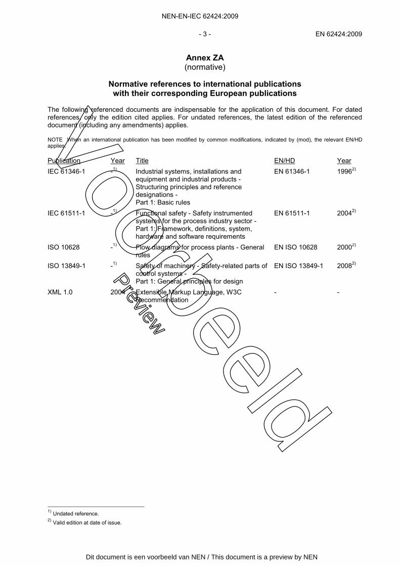
Annex ZA (normative)
Normative references to international publications
with their corresponding European publications The following referenced documents are indispensable for the application of this document. For dated references, only the edition cited applies. For undated references, the latest edition of the referenced document (including any amendments) applies. NOTE When an international publication has been modified by common modifications, indicated by (mod), the relevant EN/HD applies. Publication Year Title EN/HD Year
IEC 61346-1 -1) Industrial systems, installations and equipment and industrial products - Structuring principles and reference designations - Part 1: Basic rules
EN 61346-1 19962)
IEC 61511-1 -1) Functional safety - Safety instrumented systems for the process industry sector - Part 1: Framework, definitions, system, hardware and software requirements
EN 61511-1 20042)
ISO 10628 -1) Flow diagrams for process plants - General rules
EN ISO 10628 20002)
ISO 13849-1 -1) Safety of machinery - Safety-related parts of control systems - Part 1: General principles for design
EN ISO 13849-1 20082)
XML 1.0 2004 Extensible Markup Language, W3C Recommendation
- -
1) Undated reference. 2) Valid edition at date of issue.
NEN-EN-IEC 62424:2009
Voorbeeld
Preview
Dit document is een voorbeeld van NEN / This document is a preview by NEN

Voorbeeld
Preview
Dit document is een voorbeeld van NEN / This document is a preview by NEN
IEC 62424Edition 1.0 2008-08
INTERNATIONAL STANDARD
Representation of process control engineering – Requests in P&I diagrams and data exchange between P&ID tools and PCE-CAE tools
IEC
624
24:2
008(
E)
NEN-EN-IEC 62424:2009
Voorbeeld
Preview
Dit document is een voorbeeld van NEN / This document is a preview by NEN

THIS PUBLICATION IS COPYRIGHT PROTECTED Copyright © 2008 IEC, Geneva, Switzerland All rights reserved. Unless otherwise specified, no part of this publication may be reproduced or utilized in any form or by any means, electronic or mechanical, including photocopying and microfilm, without permission in writing from either IEC or IEC's member National Committee in the country of the requester. If you have any questions about IEC copyright or have an enquiry about obtaining additional rights to this publication, please contact the address below or your local IEC member National Committee for further information. IEC Central Office 3, rue de Varembé CH-1211 Geneva 20 Switzerland Email: [email protected] Web: www.iec.ch
About the IEC The International Electrotechnical Commission (IEC) is the leading global organization that prepares and publishes International Standards for all electrical, electronic and related technologies. About IEC publications The technical content of IEC publications is kept under constant review by the IEC. Please make sure that you have the latest edition, a corrigenda or an amendment might have been published. Catalogue of IEC publications: www.iec.ch/searchpub
The IEC on-line Catalogue enables you to search by a variety of criteria (reference number, text, technical committee,…). It also gives information on projects, withdrawn and replaced publications. IEC Just Published: www.iec.ch/online_news/justpub
Stay up to date on all new IEC publications. Just Published details twice a month all new publications released. Available on-line and also by email. Electropedia: www.electropedia.org
The world's leading online dictionary of electronic and electrical terms containing more than 20 000 terms and definitions in English and French, with equivalent terms in additional languages. Also known as the International Electrotechnical Vocabulary online. Customer Service Centre: www.iec.ch/webstore/custserv
If you wish to give us your feedback on this publication or need further assistance, please visit the Customer Service Centre FAQ or contact us: Email: [email protected] Tel.: +41 22 919 02 11 Fax: +41 22 919 03 00
NEN-EN-IEC 62424:2009
Voorbeeld
Preview
Dit document is een voorbeeld van NEN / This document is a preview by NEN

IEC 62424Edition 1.0 2008-08
INTERNATIONAL STANDARD
Representation of process control engineering – Requests in P&I diagrams and data exchange between P&ID tools and PCE-CAE tools
INTERNATIONAL ELECTROTECHNICAL COMMISSION XFICS 35.240.50; 25.040.40
PRICE CODE
ISBN 2-8318-9942-7
® Registered trademark of the International Electrotechnical Commission
NEN-EN-IEC 62424:2009
Voorbeeld
Preview
Dit document is een voorbeeld van NEN / This document is a preview by NEN

– 2 – 62424 © IEC:2008(E)
CONTENTS
FOREWORD...........................................................................................................................6 INTRODUCTION.....................................................................................................................8 1 Scope............................................................................................................................. 10 2 Normative references ..................................................................................................... 10 3 Terms and definitions ..................................................................................................... 10 4 Abbreviations ................................................................................................................. 14 5 Conformity...................................................................................................................... 15 6 Representation of PCE requests in a P&ID ..................................................................... 16
6.1 PCE request and PCE loop ................................................................................... 16 6.2 Objectives and principles ...................................................................................... 17 6.3 Requirements for the identification and representation of PCE requests ................ 17
6.3.1 General ..................................................................................................... 17 6.3.2 Types of lines ............................................................................................ 18 6.3.3 Displaying the location of the operator interface ........................................ 18 6.3.4 PCE categories and processing functions .................................................. 19 6.3.5 PCE request reference designation scheme .............................................. 22 6.3.6 PU-vendor and typical identification........................................................... 23 6.3.7 Device information..................................................................................... 23 6.3.8 Alarming, switching and indicating ............................................................. 24 6.3.9 Safety-relevant, GMP and quality-relevant PCE requests .......................... 24 6.3.10 PCE control functions ................................................................................ 25
7 Neutral data exchange of PCE relevant P&ID information ............................................... 26 7.1 Objectives ............................................................................................................. 26 7.2 Meaning of P&ID elements .................................................................................... 26 7.3 PCE relevant information of P&ID tools ................................................................. 27 7.4 Formal description of PCE relevant information of P&ID tools................................ 28
7.4.1 General ..................................................................................................... 28 7.4.2 Modeling PCE relevant information using the CAEX system
description language ................................................................................. 29 7.4.3 Basic CAEX mappings ............................................................................... 29 7.4.4 Mapping of a PCE request interface to an external interface of the
corresponding plant hierarchy item ............................................................ 31 7.4.5 CAEX description of direct links between PCE request interfaces of
different plant hierarchy items ................................................................... 33 7.4.6 PCE loops ................................................................................................. 34
8 Additional PCE attributes................................................................................................ 35 Annex A (normative) CAEX – Data model for machine information exchange ....................... 36 Annex B (informative) Examples of PCE requests .............................................................. 109 Annex C (normative) Full XML schema of the CAEX Model ................................................ 119 Annex D (informative) CAEX modelling examples .............................................................. 128 Bibliography........................................................................................................................ 135 Figure 1 – Information flow between P&ID and PCE tool .........................................................9 Figure 2 – Organization of PCE requests .............................................................................. 17 Figure 3 – General representation of a PCE-Request in a P&ID ............................................ 18
NEN-EN-IEC 62424:2009
Voorbeeld
Preview
Dit document is een voorbeeld van NEN / This document is a preview by NEN
62424 © IEC:2008(E) – 3 –
Figure 4 – Multi-sensor element ............................................................................................ 18 Figure 5 – Local interface .....................................................................................................19 Figure 6 – Manually operated switch in local control panel .................................................... 19 Figure 7 – Pressure indication in central control room........................................................... 19 Figure 8 – Example of PCE request identification ................................................................. 23 Figure 9 – Example of flow measurement with indication in the CCR delivered by vendor A specified by typical A20 ......................................................................................... 23 Figure 10 – Example of pH-measurement with indication in the CCR .................................... 23 Figure 11 – Example of flow measurement with indication in the CCR and high and low alarm .............................................................................................................................. 24 Figure 12 – Flow measurement with indication in the CCR and high alarm and a high-high switching function.......................................................................................................... 24 Figure 13 – Flow measurement with indication in the CCR and a high-high switch limit, a high alarm, a low alarm and a low-low switch limit for a safety function .............................. 24 Figure 14 – GMP relevant, safety relevant and quality relevant flow measurement with indication in the CCR ............................................................................................................ 25 Figure 15 – Control function.................................................................................................. 25 Figure 16 – Safety relevant control function .......................................................................... 25 Figure 17 – P&ID elements and associations (PCE relevant items are shown in dark lines) .................................................................................................................................... 27 Figure 18 – Process data model (PCE relevant items are shown in dark lines)...................... 28 Figure 19 – PCE request data model .................................................................................... 30 Figure 20 – Example of two plant sections and a signal connection via external interfaces.............................................................................................................................. 32 Figure 21 – Simplified CAEX model of indirect links between PCE requests across different plant hierarchy items............................................................................................... 32 Figure 22 – Example of two plant sections and a direct connection ....................................... 33 Figure 23 – Simplified CAEX model of direct links between PCE requests across different plant hierarchy items............................................................................................... 34 Figure A.1 – CAEX architecture of a SystemUnitClass .......................................................... 42 Figure A.2 – Example of a SystemUnitClassLib..................................................................... 42 Figure A.3 – Examples of Attributes ...................................................................................... 44 Figure A.4 – Examples of an InterfaceClassLib ..................................................................... 46 Figure A.5 – Usage of Links.................................................................................................. 47 Figure A.6 – Example of a RoleClassLib ............................................................................... 48 Figure A.7 – CAEX Role Concept.......................................................................................... 50 Figure A.8 – CAEX data definition for use case 1.................................................................. 50 Figure A.9 – CAEX data definition for use case 2.................................................................. 51 Figure A.10 – CAEX data definition for use case 3 ................................................................ 51 Figure A.11 – CAEX data definition of a MappingObject........................................................ 53 Figure A.12 – Example for a hierarchical plant structure ....................................................... 53 Figure A.13 – CAEX data structure ....................................................................................... 54 Figure A.14 – Distribution of data in several CAEX files ........................................................ 54 Figure A.15 – Referencing of external CAEX files ................................................................. 54 Figure A.16 – Example of how to use alias names ................................................................ 55 Figure A.17 – Multiple crossed structures ............................................................................. 56
NEN-EN-IEC 62424:2009
Voorbeeld
Preview
Dit document is een voorbeeld van NEN / This document is a preview by NEN
– 4 – 62424 © IEC:2008(E)
Figure B.1 – Local level indication, 1 process connection ................................................... 109 Figure B.2 – Local level indication, 2 process connections .................................................. 109 Figure B.3 – Local flow indication ....................................................................................... 109 Figure B.4 – Local pressure indication ................................................................................ 109 Figure B.5 – Local temperature indication ........................................................................... 109 Figure B.6 – Local control panel, pressure indication, high alarm ........................................ 110 Figure B.7 – Local temperature indication, CCR temperature high alarm............................. 110 Figure B.8 – Local pressure indication, CCR pressure high alarm and switch...................... 110 Figure B.9 – CCR flow indication, device information: Orifice Plate ..................................... 110 Figure B.10 – CCR pressure indication, low, low low and high alarm .................................. 110 Figure B.11 – CCR temperature indication and registration ................................................. 111 Figure B.12 – CCR level indication and registration, 1 process connection ......................... 111 Figure B.13 – CCR level indication, 2 process connections ................................................. 111 Figure B.14 – Two flow indications and flow ratio control in CCR ........................................ 111 Figure B.15 – CCR flow indication and high alarm, flow control, control valve with extra interlock and open/close indication ..................................................................................... 112 Figure B.16 – Local pressure indication, CCR pressure indication, high alarm and high high safety relevant switch.................................................................................................. 112 Figure B.17 – Local pressure indication, CCR pressure indication, alarms and switches ..... 112 Figure B.18 – CCR pressure indication, high and low alarm, safety relevant switch action on on/off valve.......................................................................................................... 112 Figure B.19 – Switched valve with on/off indication and switching action, safety relevant switched valve....................................................................................................... 113 Figure B.20– Pressure restriction........................................................................................ 113 Figure B.21 – Flow restriction ............................................................................................. 113 Figure B.22 – PT compensated flow control, safety-relevant pressure switch (two out of three (2oo3) shutdown), switched control valve with on/off indication and switching action at open position ........................................................................................................ 114 Figure B.23 – CCR temperature control, additional manual switch actions from CCR with indication and local control panel................................................................................. 114 Figure B.24 – Motor typical, local on/off control, CCR off control, current, fault with alarm and running indication ............................................................................................... 115 Figure B.25 – Multivariable controller .................................................................................. 115 Figure B.26 – On/off valve with position indication .............................................................. 116 Figure B.27 – On/off valve with safety relevant switch and position indication ..................... 116 Figure B.28 – Level control with continuous controller......................................................... 116 Figure B.29 – Level control with on/off switch ..................................................................... 116 Figure B.30 – Cascade control for temperature as control input, flow control as follow-up controller ....................................................................................................................... 117 Figure B.31 – Safety directed high control to a subsequent valve, manual control for reset function and manual control for manual/automatic switch of the valve, valve with open/close indication and safety-relevant switch to subsequent valve ................................. 117 Figure B.32 – Flow control in CCR ...................................................................................... 117 Figure B.33 – Temperature control with high alarm and high switch .................................... 117 Figure B.34 – Manual control from CCR.............................................................................. 118 Figure B.35 – Flow measurement with display and alarms in CCR, high high switch on process control function and switch on/off valve ................................................................. 118
NEN-EN-IEC 62424:2009
Voorbeeld
Preview
Dit document is een voorbeeld van NEN / This document is a preview by NEN

62424 © IEC:2008(E) – 5 –
Figure B.36 – Local P-/F-/T-/S- control without auxiliary power (stand-alone)...................... 118 Figure D.1 – Example CAEX interface library ...................................................................... 128 Figure D.2 – Example CAEX role library ............................................................................. 129 Figure D.3 – Example to be mapped with CAEX.................................................................. 131 Figure D.4 – CAEX model of the example described in Figure D.3 ...................................... 132 Table 1 – Abbrevations .........................................................................................................15 Table 2 – PCE categories ..................................................................................................... 20 Table 3 – PCE processing function ....................................................................................... 21 Table 4 – Sequence combinations ........................................................................................ 22 Table 5 – PCE processing functions for actuators ................................................................. 22 Table 6 – P&ID attributes relevant in PCE environment ........................................................ 35 Table 7 – Data handling attributes ........................................................................................ 35 Table A.1 – XML notation conventions .................................................................................. 36 Table A.2 – CAEX data types and elements .......................................................................... 37
NEN-EN-IEC 62424:2009
Voorbeeld
Preview
Dit document is een voorbeeld van NEN / This document is a preview by NEN

Via het digitale platform NEN Connect heeft u altijd toegang
tot de meest actuele versie van deze norm. Vervallen versies
blijven ook beschikbaar. U en uw collega’s kunnen de norm
via NEN Connect makkelijk raadplagen, online en offline.
Kies voor slimmer werken en bekijk onze mogelijkheden op
www.nenconnect.nl.
Heeft u vragen?Onze Klantenservice is bereikbaar maandag tot en met vrijdag,
van 8.30 tot 17.00 uur.
Telefoon: 015 2 690 391
E-mail: [email protected]
ALTIJD DE ACTUELE NORMIN UW BEZIT HEBBEN?Nooit meer zoeken in de systemen en uzelf de vraag stellen:
WERK SLIMMER MET NEN CONNECT
‘Is NEN-EN-IEC 62424:2009 en de laatste versie?’