TOOLING ESSENTIALS
104
LVDGROUP.COM TOOLING ESSENTIALS
Transcript of TOOLING ESSENTIALS
LVDGROUP.COM
TOOLING ESSENTIALS
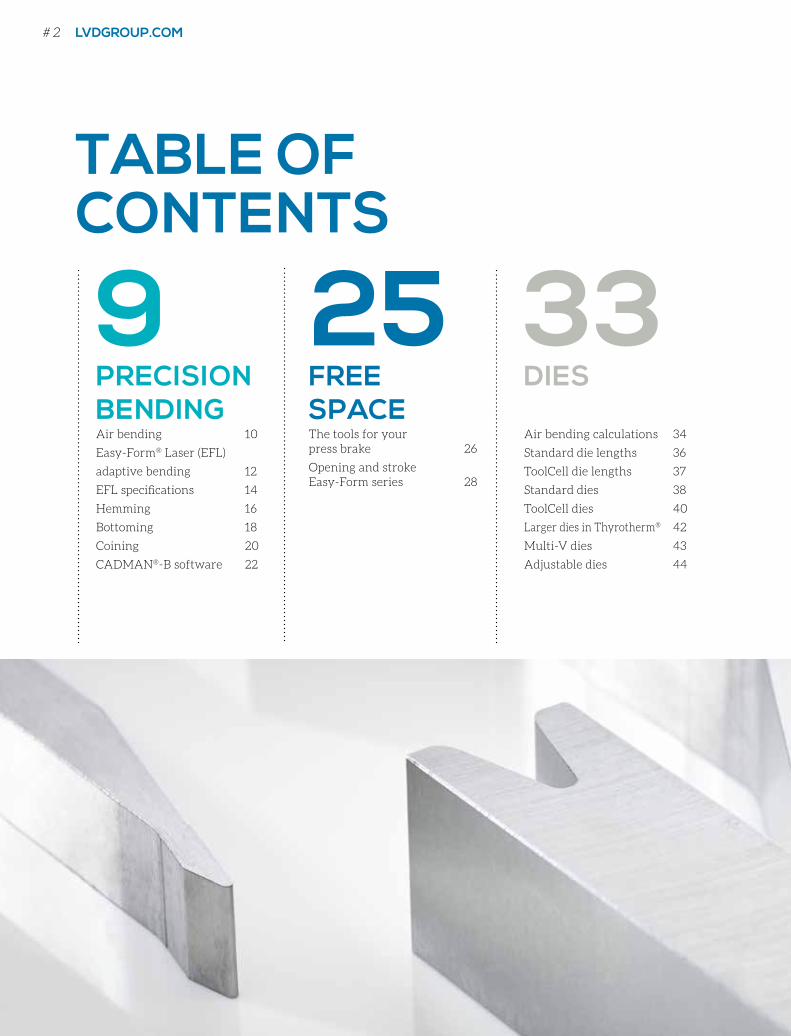
TABLE OF CONTENTS
9 25 33PRECISION BENDINGAir bending 10
Easy-Form® Laser (EFL)
adaptive bending 12
EFL specifications 14
Hemming 16
Bottoming 18
Coining 20
CADMAN®-B software 22
FREE SPACEThe tools for yourpress brake 26
Opening and stroke Easy-Form series 28
DIES
Air bending calculations 34
Standard die lengths 36
ToolCell die lengths 37
Standard dies 38
ToolCell dies 40
Larger dies in Thyrotherm® 42
Multi-V dies 43
Adjustable dies 44
# 2 LVDGROUP.COM
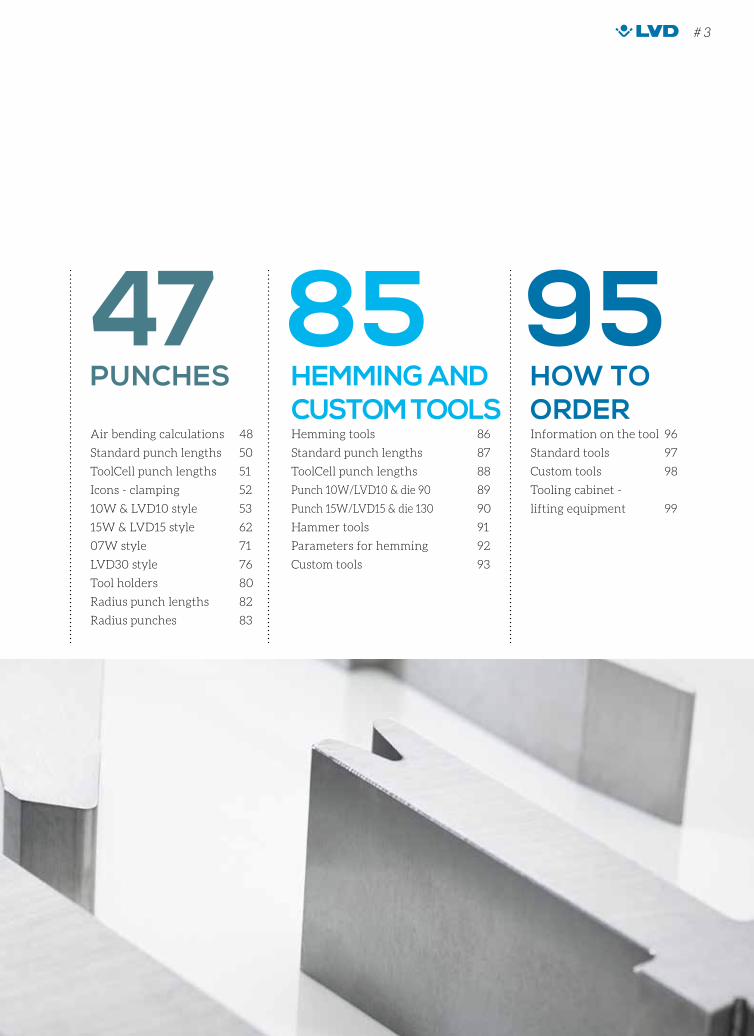
47 85 95PUNCHES
Air bending calculations 48
Standard punch lengths 50
ToolCell punch lengths 51
Icons - clamping 52
10W & LVD10 style 53
15W & LVD15 style 62
07W style 71
LVD30 style 76
Tool holders 80
Radius punch lengths 82
Radius punches 83
HEMMING AND CUSTOM TOOLS Hemming tools 86
Standard punch lengths 87
ToolCell punch lengths 88
Punch 10W/LVD10 & die 90 89
Punch 15W/LVD15 & die 130 90
Hammer tools 91
Parameters for hemming 92
Custom tools 93
HOW TO ORDERInformation on the tool 96
Standard tools 97
Custom tools 98
Tooling cabinet -
lifting equipment 99
# 3
VOORWOORDBij plooigereedschappen is het belangrijk het juiste gereedschap voor de job te kiezen.
Om aan de wensen van de klanten te voldoen, hebben onze ingenieurs de vorm van de
boven- en ondergereedschappen geoptimaliseerd zodat u met eenzelfde gereedschap meer
verschillende stukken kunt plooien. De nieuwe sectielengtes van de gedeelde gereedschappen
zorgen voor nog meer flexibiliteit.
Tooling Essentials biedt meer informatie over onze standaardgereedschappen voor
afkantpersen van 120 tot 30.000 kN. LVD helpt u graag bij het bepalen van de juiste
gereedschappen voor uw toepassing.
Ga naar de tab “How to order” voor meer informatie over het bestellen van gereedschappen.
Heeft u vragen of wenst u ondersteuning, contacteer dan uw locale LVD-agent via lvdgroup.com
of contacteer ons rechtstreeks via [email protected].
Nl
# 4 LVDGROUP.COM
PREFACE
When it comes to press brake tooling, it’s important to select the right
tool for the job. To meet customer requirements, our engineers have
optimised the shape of the upper and lower tools, so you can bend a
wider variety of parts with the same tool. New section lengths for
segmented tooling further improve the flexibility.
Tooling Essentials provides detailed information on our standard tooling
for press brakes from 120 to 30,000 kN. LVD is ready to help you make
the right choice of tooling for your application.
For complete details on how to order tooling, turn to the tab “How to order”.
If you have questions or need support, please contact your local LVD
agent at lvdgroup.com or reach us directly at [email protected].
En
PRÉFACELorsqu’il s’agit d’outils pour presses plieuses, il est important de choisir le bon outil pour
le bon usage. Afin de répondre aux exigences des clients, nos ingénieurs ont optimisé
la forme des outils supérieurs et inférieurs pour plier une plus grande variété de pièces
avec le même outil. De nouvelles longueurs fractionnées viennent s’ajouter à notre
gamme pour une meilleure flexibilité.
Tooling Essentials présente de plus amples informations sur nos outils standard pour
presses plieuses de 120 à 30.000 kN. LVD se tient à votre disposition pour choisir les
meilleurs outils nécessaires à votre application.
Allez à l’onglet “How to order” pour plus de détails sur la façon de commander des outils.
Pour toute question ou tout besoin d’assistance, contactez votre agent LVD local sur
lvdgroup.com ou adressez-nous directement votre demande sur [email protected].
VORWORTBei Abkantwerkzeuge ist es wichtig das richtige Werkzeug für die Anwendung zu wählen.
Um die Kundenanforderungen zu erfüllen, haben unsere Ingenieure die Form der Ober- und
Unterwerkzeuge optimiert, sodass Sie eine breitere Palette von Werkstücken mit demselben
Werkzeug biegen können. Die neuen Sektionslängen der segmentierten Werkzeuge sorgen für
eine bessere Flexibilität.
Tooling Essentials enthält ausführlichere Informationen über Standardwerkzeuge für
Abkantpressen von 120 bis 30.000 kN. LVD hilft Ihnen gerne bei der korrekten Auswahl der
Werkzeuge für Ihre Anwendung.
Um ausführliche Informationen zum Bestellen von Werkzeugen zu erhalten, gehen Sie zum
Tab “How to order”. Wenn Sie Fragen haben oder weitere Unterstützung benötigen, wenden
Sie sich bitte an Ihre lokale LVD-Vertretung auf lvdgroup.com oder kontaktieren Sie uns direkt
über [email protected].
Fr
De
# 5
# 6 LVDGROUP.COM
WHY LVD TOOLS?
LVD manufactures high quality, precision-ground tooling
made from the best materials for maximum resistance and
long life.
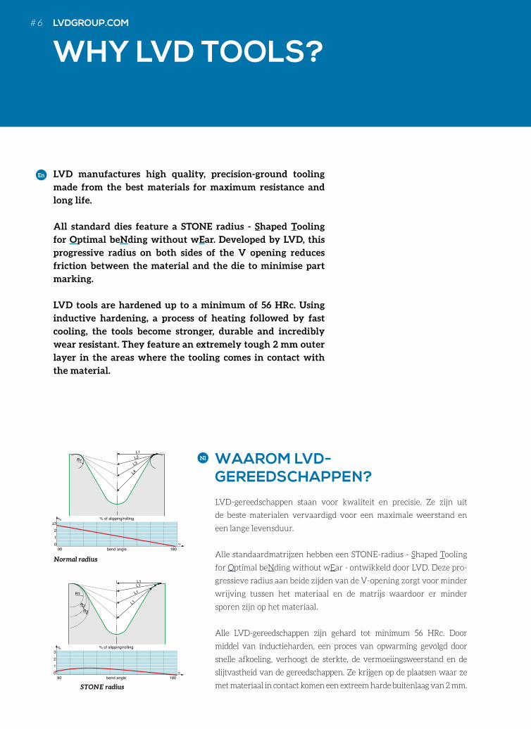
All standard dies feature a STONE radius - Shaped Tooling
for Optimal beNding without wEar. Developed by LVD, this
progressive radius on both sides of the V opening reduces
friction between the material and the die to minimise part
marking.
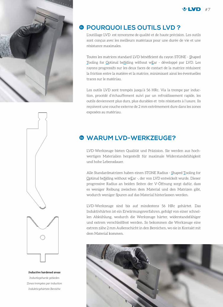
LVD tools are hardened up to a minimum of 56 HRc. Using
inductive hardening, a process of heating followed by fast
cooling, the tools become stronger, durable and incredibly
wear resistant. They feature an extremely tough 2 mm outer
layer in the areas where the tooling comes in contact with
the material.
En
WAAROM LVD- GEREEDSCHAPPEN?
LVD-gereedschappen staan voor kwaliteit en precisie. Ze zijn uit
de beste materialen vervaardigd voor een maximale weerstand en
een lange levensduur.
Alle standaardmatrijzen hebben een STONE-radius - Shaped Tooling
for Optimal beNding without wEar - ontwikkeld door LVD. Deze pro-
gressieve radius aan beide zijden van de V-opening zorgt voor minder
wrijving tussen het materiaal en de matrijs waardoor er minder
sporen zijn op het materiaal.
Alle LVD-gereedschappen zijn gehard tot minimum 56 HRc. Door
middel van inductieharden, een proces van opwarming gevolgd door
snelle afkoeling, verhoogt de sterkte, de vermoeiingsweerstand en de
slijtvastheid van de gereedschappen. Ze krijgen op de plaatsen waar ze
met materiaal in contact komen een extreem harde buitenlaag van 2 mm.
Nl
STONE radius
Normal radius
α 90
%
bend angle
% of slipping/rolling
0123
180
α 90
%
bend angle
% of slipping/rolling
012
±3
180
L1
R1
R1
R2R3
L1L1
L1
L1
L2
L3
L4
α 90
%
bend angle
% of slipping/rolling
0123
180
α 90
%
bend angle
% of slipping/rolling
012
±3
180
L1
R1
R1
R2R3
L1L1
L1
L1
L2
L3
L4
POURQUOI LES OUTILS LVD ?L’outillage LVD est synonyme de qualité et de haute précision. Les outils
sont conçus avec les meilleurs matériaux pour une durée de vie et une
résistance maximales.
Toutes les matrices standard LVD bénéficient du rayon STONE - Shaped
Tooling for Optimal beNding without wEar - développé par LVD. Les
rayons progressifs sur les deux faces de contact de la matrice réduisent
la friction entre la matière et la matrice, minimisant ainsi les éventuelles
traces sur le matériau.
Les outils LVD sont trempés jusqu’à 56 HRc. Via la trempe par induc-
tion, procédé d’échauffement suivi par un refroidissement rapide, les
outils deviennent plus durs, plus durables et très résistants à l’usure. Ils
reçoivent une couche externe de 2 mm extrêmement dure dans les zones
exposées au matériau.
Fr
WARUM LVD-WERKZEUGE?
LVD-Werkzeuge bieten Qualität und Präzision. Sie werden aus hoch-
wertigen Materialien hergestellt für maximale Widerstandsfähigkeit
und hohe Lebensdauer.
Alle Standardmatrizen haben einen STONE Radius - Shaped Tooling for
Optimal beNding without wEar -, der von LVD entwickelt wurde. Dieser
progressive Radius an beiden Seiten der V-Öffnung sorgt dafür, dass
es weniger Reibung zwischen dem Material und den Matrizen gibt,
wodurch weniger Spuren auf das Material hinterlassen werden.
LVD-Werkzeuge sind bis auf mindestens 56 HRc gehärtet. Das
Induktivhärten ist ein Erwärmungsverfahren, gefolgt von einer schnel-
len Abkühlung, wodurch die Werkzeuge härter, widerstandsfähiger
und extrem verschleißfest werden. So bekommen die Werkzeuge eine
extrem zähe 2 mm Außenschicht in den Bereichen, wo sie in Kontakt mit
dem Material kommen.
De
Inductive hardened areas
Inductiegeharde gebieden
Zones trempées par induction
Induktivgehärtete Bereiche
# 7
To identify the right person in a group of thousands, you only need to look at his fingers. But where do you look when you want to find the best measuring and control technology? You can recognize HEIDENHAIN by many characteristics, but especially by our passion for precision. From the everyday encoder in the machine tool to the nanometer-precise length comparator... for more than 125 years, HEIDENHAIN has been the measure for accuracy. We invest continuously in this technical difference. And you profit from products that are not only innovative, economical and reliable, but also characterized down to their smallest details by unmistakable precision.
How do you identify the right measuring
technology?
HEIDENHAIN nv/sa 1760 Roosdaal, Belgium Telefoon: +32 54 34 31 58 www.heidenhain.be
Angle Encoders Linear Encoders Contouring Controls Position Displays Length Gauges Rotary Encoders
PR
EC
ISIO
N B
EN
DIN
G
EXACT PLOOIENPLIAGE DE PRECISIONPRÄZISES BIEGEN
PRECISIONBENDING
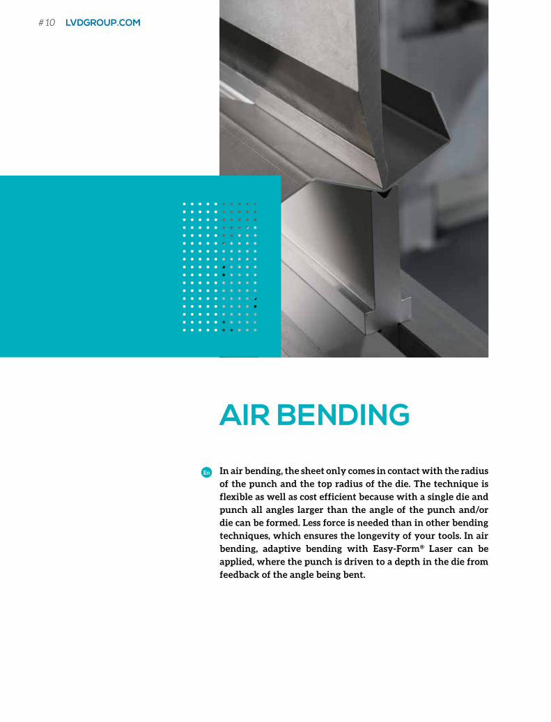
AIR BENDING
In air bending, the sheet only comes in contact with the radius
of the punch and the top radius of the die. The technique is
flexible as well as cost efficient because with a single die and
punch all angles larger than the angle of the punch and/or
die can be formed. Less force is needed than in other bending
techniques, which ensures the longevity of your tools. In air
bending, adaptive bending with Easy-Form® Laser can be
applied, where the punch is driven to a depth in the die from
feedback of the angle being bent.
En
# 10 LVDGROUP.COM
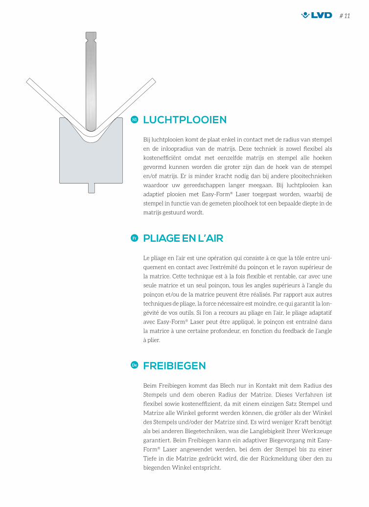
LUCHTPLOOIEN
Bij luchtplooien komt de plaat enkel in contact met de radius van stempel
en de inloopradius van de matrijs. Deze techniek is zowel flexibel als
kostenefficiënt omdat met eenzelfde matrijs en stempel alle hoeken
gevormd kunnen worden die groter zijn dan de hoek van de stempel
en/of matrijs. Er is minder kracht nodig dan bij andere plooitechnieken
waardoor uw gereedschappen langer meegaan. Bij luchtplooien kan
adaptief plooien met Easy-Form® Laser toegepast worden, waarbij de
stempel in functie van de gemeten plooihoek tot een bepaalde diepte in de
matrijs gestuurd wordt.
Nl
PLIAGE EN L’AIR
Le pliage en l’air est une opération qui consiste à ce que la tôle entre uni-
quement en contact avec l’extrémité du poinçon et le rayon supérieur de
la matrice. Cette technique est à la fois flexible et rentable, car avec une
seule matrice et un seul poinçon, tous les angles supérieurs à l’angle du
poinçon et/ou de la matrice peuvent être réalisés. Par rapport aux autres
techniques de pliage, la force nécessaire est moindre, ce qui garantit la lon-
gévité de vos outils. Si l’on a recours au pliage en l’air, le pliage adaptatif
avec Easy-Form® Laser peut être appliqué, le poinçon est entraîné dans
la matrice à une certaine profondeur, en fonction du feedback de l’angle
à plier.
Fr
FREIBIEGEN
Beim Freibiegen kommt das Blech nur in Kontakt mit dem Radius des
Stempels und dem oberen Radius der Matrize. Dieses Verfahren ist
flexibel sowie kosteneffizient, da mit einem einzigen Satz Stempel und
Matrize alle Winkel geformt werden können, die größer als der Winkel
des Stempels und/oder der Matrize sind. Es wird weniger Kraft benötigt
als bei anderen Biegetechniken, was die Langlebigkeit Ihrer Werkzeuge
garantiert. Beim Freibiegen kann ein adaptiver Biegevorgang mit Easy-
Form® Laser angewendet werden, bei dem der Stempel bis zu einer
Tiefe in die Matrize gedrückt wird, die der Rückmeldung über den zu
biegenden Winkel entspricht.
De
# 11
EASY-FORM® LASER (EFL) ADAPTIVE BENDINGADAPTIEF PLOOIEN / PLIAGE ADAPTIF / ADAPTIVES BIEGEN
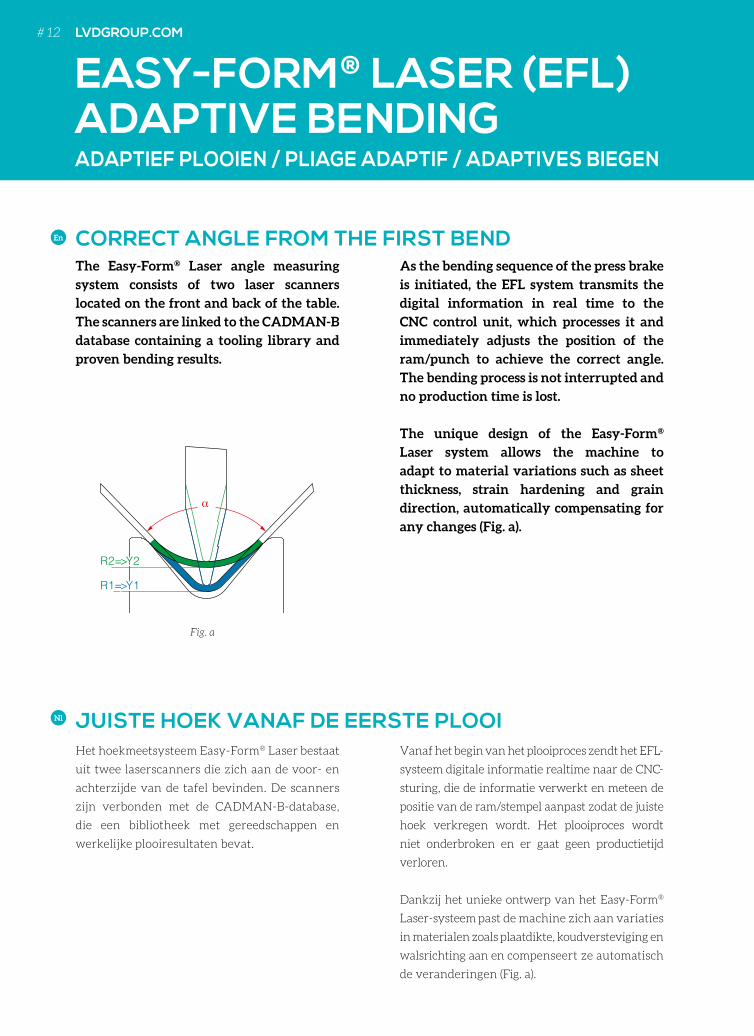
As the bending sequence of the press brake
is initiated, the EFL system transmits the
digital information in real time to the
CNC control unit, which processes it and
immediately adjusts the position of the
ram/punch to achieve the correct angle.
The bending process is not interrupted and
no production time is lost.
The unique design of the Easy-Form®
Laser system allows the machine to
adapt to material variations such as sheet
thickness, strain hardening and grain
direction, automatically compensating for
any changes (Fig. a).
The Easy-Form® Laser angle measuring
system consists of two laser scanners
located on the front and back of the table.
The scanners are linked to the CADMAN-B
database containing a tooling library and
proven bending results.
En
Het hoekmeetsysteem Easy-Form® Laser bestaat
uit twee laserscanners die zich aan de voor- en
achterzijde van de tafel bevinden. De scanners
zijn verbonden met de CADMAN-B-database,
die een bibliotheek met gereedschappen en
werkelijke plooiresultaten bevat.
Vanaf het begin van het plooiproces zendt het EFL-
systeem digitale informatie realtime naar de CNC-
sturing, die de informatie verwerkt en meteen de
positie van de ram/stempel aanpast zodat de juiste
hoek verkregen wordt. Het plooiproces wordt
niet onderbroken en er gaat geen productietijd
verloren.
Dankzij het unieke ontwerp van het Easy-Form®
Laser-systeem past de machine zich aan variaties
in materialen zoals plaatdikte, koudversteviging en
walsrichting aan en compenseert ze automatisch
de veranderingen (Fig. a).
Nl
α
R2=>Y2
R1=>Y1
R2=>Y2
R1=>Y1
Fig. a
CORRECT ANGLE FROM THE FIRST BEND
JUISTE HOEK VANAF DE EERSTE PLOOI
# 12 LVDGROUP.COM
Le système de mesure d’angle Easy-Form® Laser se
compose de deux capteurs laser situés à l’avant et
à l’arrière de la table. Les capteurs sont reliés à la
base de données CADMAN-B contenant des para-
mètres de pliage certifiés, liés à une bibliothèque
d’outils.
Au début de la séquence de pliage, le système
EFL transmet les informations numériques en
temps réel à l’unité de commande numérique, qui
les traite et adapte immédiatement la position du
coulisseau/poinçon afin d’obtenir le bon angle. Ce
procédé n’interrompt pas le processus de pliage et
ne génère aucune perte de temps de fabrication.
La conception unique du système Easy-Form®
Laser permet à la machine de s’adapter aux varia-
tions de matériaux telles que l’épaisseur de la tôle,
l’écrouissage et le sens de laminage et de compen-
ser automatiquement toute modification (Fig. a).
Fr
Das Winkelmess-System Easy-Form® Laser
besteht aus zwei Laserscannern, die sich an der
Vorder- und Rückseite des Tisches befinden. Die
Scanner sind mit der CADMAN-B Datenbank
gekoppelt, die ein Verzeichnis der Werkzeuge
und geprüfter Biegeergebnisse beinhaltet.
Sobald der Biegeablauf der Abkantpresse
gestartet ist, übermittelt das EFL-System
digitale Informationen in Echtzeit an die CNC-
Steuereinheit, welche diese verarbeitet und
unmittelbar die Stößel-/Stempelposition anpasst,
um den korrekten Winkel zu erzielen. Der
Biegeprozess wird dabei nicht unterbrochen,
sodass keine Produktionszeit verloren geht.
Die einzigartige Ausführung des Easy-Form®
Laser-Systems ermöglicht es der Abkantpresse,
sich an Materialschwankungen wie Blechstärke,
Verfestigungen und Körnungsverlauf
anzupassen und automatisch alle Abweichungen
zu kompensieren (Abb. a).
De
L’ANGLE CORRECT DÈS LE PREMIER PLI
EXAKTER WINKEL VOM ERSTEN WERKSTÜCK
# 13# 13
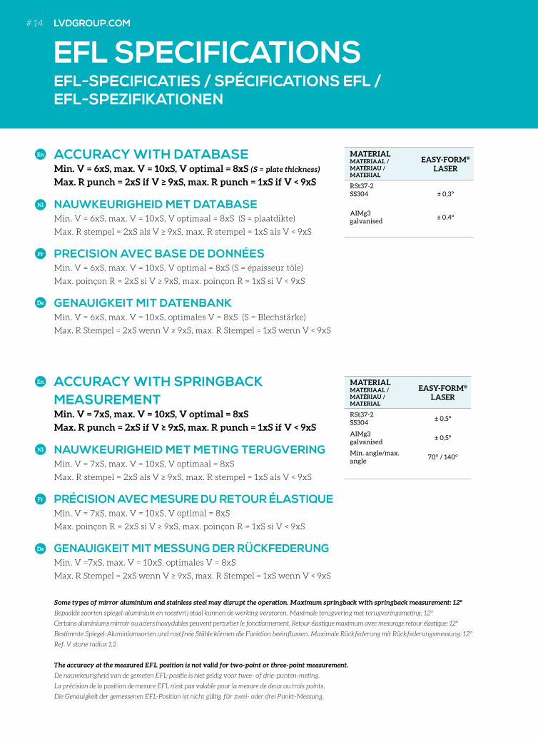
ACCURACY WITH SPRINGBACK MEASUREMENTMin. V = 7xS, max. V = 10xS, V optimal = 8xS
Max. R punch = 2xS if V ≥ 9xS, max. R punch = 1xS if V < 9xS
NAUWKEURIGHEID MET METING TERUGVERING Min. V = 7xS, max. V = 10xS, V optimaal = 8xS
Max. R stempel = 2xS als V ≥ 9xS, max. R stempel = 1xS als V < 9xS
PRÉCISION AVEC MESURE DU RETOUR ÉLASTIQUE Min. V = 7xS, max. V = 10xS, V optimal = 8xS
Max. poinçon R = 2xS si V ≥ 9xS, max. poinçon R = 1xS si V < 9xS
GENAUIGKEIT MIT MESSUNG DER RÜCKFEDERUNG Min. V =7xS, max. V = 10xS, optimales V = 8xS
Max. R Stempel = 2xS wenn V ≥ 9xS, max. R Stempel = 1xS wenn V < 9xS
Some types of mirror aluminium and stainless steel may disrupt the operation. Maximum springback with springback measurement: 12°
Bepaalde soorten spiegel-aluminium en roestvrij staal kunnen de werking verstoren. Maximale terugvering met terugveringsmeting: 12°
Certains aluminiums mirroir ou aciers inoxydables peuvent perturber le fonctionnement. Retour élastique maximum avec mesurage retour élastique: 12°
Bestimmte Spiegel-Aluminiumsorten und rostfreie Stähle können die Funktion beeinflussen. Maximale Rückfederung mit Rückfederungsmessung: 12°
Ref. V stone radius 1,2
The accuracy at the measured EFL position is not valid for two-point or three-point measurement.
De nauwkeurigheid van de gemeten EFL-positie is niet geldig voor twee- of drie-punten-meting.
La précision de la position de mesure EFL n’est pas valable pour la mesure de deux ou trois points.
Die Genauigkeit der gemessenen EFL-Position ist nicht gültig für zwei- oder drei Punkt-Messung.
MATERIAL MATERIAAL / MATÉRIAU / MATERIAL
EASY-FORM® LASER
RSt37-2SS304
± 0,5°
AIMg3galvanised
± 0,5°
Min. angle/max. angle
70° / 140°
EFL-SPECIFICATIES / SPÉCIFICATIONS EFL / EFL-SPEZIFIKATIONEN
En
Nl
Fr
De
ACCURACY WITH DATABASE Min. V = 6xS, max. V = 10xS, V optimal = 8xS (S = plate thickness)
Max. R punch = 2xS if V ≥ 9xS, max. R punch = 1xS if V < 9xS
NAUWKEURIGHEID MET DATABASE Min. V = 6xS, max. V = 10xS, V optimaal = 8xS (S = plaatdikte)
Max. R stempel = 2xS als V ≥ 9xS, max. R stempel = 1xS als V < 9xS
PRECISION AVEC BASE DE DONNÉES Min. V = 6xS, max. V = 10xS, V optimal = 8xS (S = épaisseur tôle)
Max. poinçon R = 2xS si V ≥ 9xS, max. poinçon R = 1xS si V < 9xS
GENAUIGKEIT MIT DATENBANK Min. V = 6xS, max. V = 10xS, optimales V = 8xS (S = Blechstärke)
Max. R Stempel = 2xS wenn V ≥ 9xS, max. R Stempel = 1xS wenn V < 9xS
MATERIAL MATERIAAL / MATÉRIAU / MATERIAL
EASY-FORM® LASER
RSt37-2SS304 ± 0,3°
AIMg3galvanised
± 0,4°
En
Nl
Fr
De
EFL SPECIFICATIONS# 14 LVDGROUP.COM
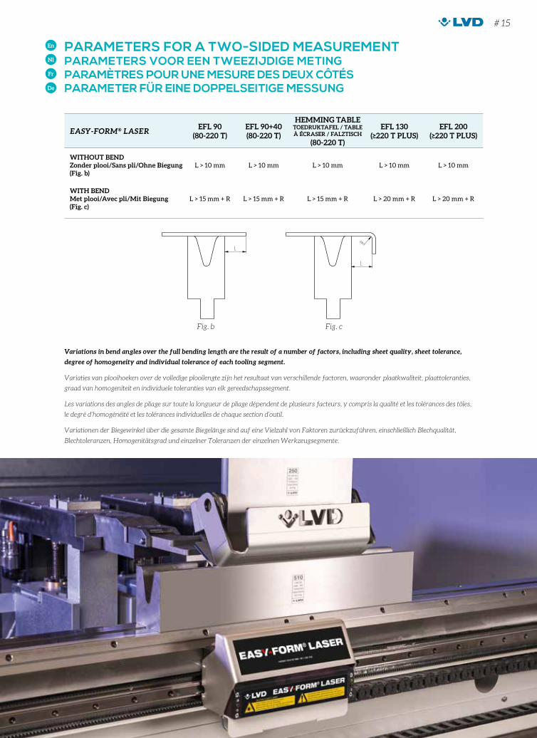
PARAMETERS FOR A TWO-SIDED MEASUREMENT PARAMETERS VOOR EEN TWEEZIJDIGE METING PARAMÈTRES POUR UNE MESURE DES DEUX CÔTÉS PARAMETER FÜR EINE DOPPELSEITIGE MESSUNG
En
Nl
Fr
De
EASY-FORM® LASEREFL 90
(80-220 T)EFL 90+40 (80-220 T)
HEMMING TABLETOEDRUKTAFEL / TABLE À ÉCRASER / FALZTISCH
(80-220 T)
EFL 130 (≥220 T PLUS)
EFL 200(≥220 T PLUS)
WITHOUT BENDZonder plooi/Sans pli/Ohne Biegung(Fig. b)
L > 10 mm L > 10 mm L > 10 mm L > 10 mm L > 10 mm
WITH BENDMet plooi/Avec pli/Mit Biegung(Fig. c)
L > 15 mm + R L > 15 mm + R L > 15 mm + R L > 20 mm + R L > 20 mm + R
Fig. b Fig. c
Variations in bend angles over the full bending length are the result of a number of factors, including sheet quality, sheet tolerance,
degree of homogeneity and individual tolerance of each tooling segment.
Variaties van plooihoeken over de volledige plooilengte zijn het resultaat van verschillende factoren, waaronder plaatkwaliteit, plaattoleranties,
graad van homogeniteit en individuele toleranties van elk gereedschapssegment.
Les variations des angles de pliage sur toute la longueur de pliage dépendent de plusieurs facteurs, y compris la qualité et les tolérances des tôles,
le degré d’homogénéité et les tolérances individuelles de chaque section d’outil.
Variationen der Biegewinkel über die gesamte Biegelänge sind auf eine Vielzahl von Faktoren zurückzuführen, einschließlich Blechqualität,
Blechtoleranzen, Homogenitätsgrad und einzelner Toleranzen der einzelnen Werkzeugsegmente.
# 15
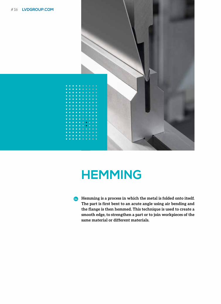
HEMMING
Hemming is a process in which the metal is folded onto itself.
The part is first bent to an acute angle using air bending and
the flange is then hemmed. This technique is used to create a
smooth edge, to strengthen a part or to join workpieces of the
same material or different materials.
En
# 16 LVDGROUP.COM
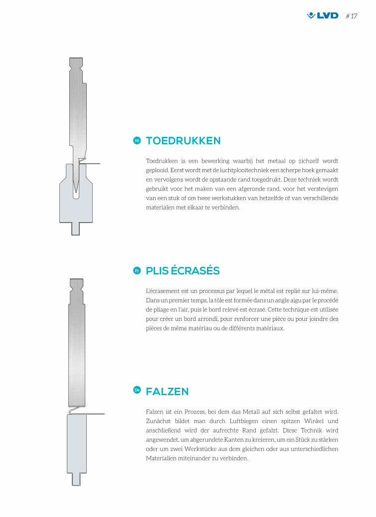
TOEDRUKKEN
Toedrukken is een bewerking waarbij het metaal op zichzelf wordt
geplooid. Eerst wordt met de luchtplooitechniek een scherpe hoek gemaakt
en vervolgens wordt de opstaande rand toegedrukt. Deze techniek wordt
gebruikt voor het maken van een afgeronde rand, voor het verstevigen
van een stuk of om twee werkstukken van hetzelfde of van verschillende
materialen met elkaar te verbinden.
Nl
PLIS ÉCRASÉS
L’écrasement est un processus par lequel le métal est replié sur lui-même.
Dans un premier temps, la tôle est formée dans un angle aigu par le procédé
de pliage en l’air, puis le bord relevé est écrasé. Cette technique est utilisée
pour créer un bord arrondi, pour renforcer une pièce ou pour joindre des
pièces de même matériau ou de différents matériaux.
Fr
FALZEN
Falzen ist ein Prozess, bei dem das Metall auf sich selbst gefaltet wird.
Zunächst bildet man durch Luftbiegen einen spitzen Winkel und
anschließend wird der aufrechte Rand gefalzt. Diese Technik wird
angewendet, um abgerundete Kanten zu kreieren, um ein Stück zu stärken
oder um zwei Werkstücke aus dem gleichen oder aus unterschiedlichen
Materialien miteinander zu verbinden.
De
HEMMING
# 17
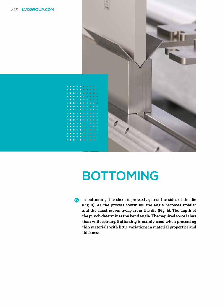
BOTTOMING
In bottoming, the sheet is pressed against the sides of the die
(Fig. a). As the process continues, the angle becomes smaller
and the sheet moves away from the die (Fig. b). The depth of
the punch determines the bend angle. The required force is less
than with coining. Bottoming is mainly used when processing
thin materials with little variations in material properties and
thickness.
En
# 18 LVDGROUP.COM
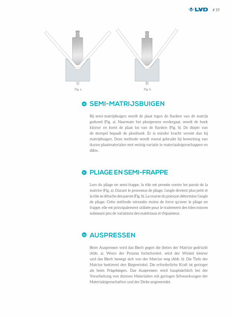
SEMI-MATRIJSBUIGEN
Bij semi-matrijsbuigen wordt de plaat tegen de flanken van de matrijs
geduwd (Fig. a). Naarmate het plooiproces verdergaat, wordt de hoek
kleiner en komt de plaat los van de flanken (Fig. b). De diepte van
de stempel bepaalt de plooihoek. Er is minder kracht vereist dan bij
matrijsbuigen. Deze methode wordt vooral gebruikt bij bewerking van
dunne plaatmaterialen met weinig variatie in materiaaleigenschappen en
dikte.
Nl
PLIAGE EN SEMI-FRAPPE
Lors du pliage en semi-frappe, la tôle est pressée contre les parois de la
matrice (Fig. a). Durant le processus de pliage, l’angle devient plus petit et
la tôle se détache des parois (Fig. b). La course du poinçon détermine l’angle
de pliage. Cette méthode nécessite moins de force qu’avec le pliage en
frappe, elle est principalement utilisée pour le traitement des tôles minces
subissant peu de variations des matériaux et d’épaisseur.
Fr
AUSPRESSEN
Beim Auspressen wird das Blech gegen die Seiten der Matrize gedrückt
(Abb. a). Wenn der Prozess fortschreitet, wird der Winkel kleiner
und das Blech bewegt sich von der Matrize weg (Abb. b). Die Tiefe der
Matrize bestimmt den Biegewinkel. Die erforderliche Kraft ist geringer
als beim Prägebiegen. Das Auspressen wird hauptsächlich bei der
Verarbeitung von dünnen Materialien mit geringen Schwankungen der
Materialeigenschaften und der Dicke angewendet.
De
BOTTOMING
Fig. a Fig. b
# 19
COINING
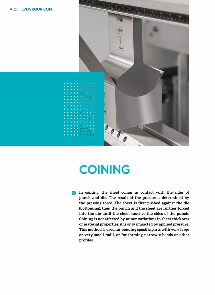
In coining, the sheet comes in contact with the sides of
punch and die. The result of the process is determined by
the pressing force. The sheet is first pushed against the die
(bottoming), then the punch and the sheet are further forced
into the die until the sheet touches the sides of the punch.
Coining is not affected by minor variations in sheet thickness
or material properties; it is only impacted by applied pressure.
This method is used for bending specific parts with very large
or very small radii, or for forming narrow z-bends or other
profiles.
En
# 20 LVDGROUP.COM
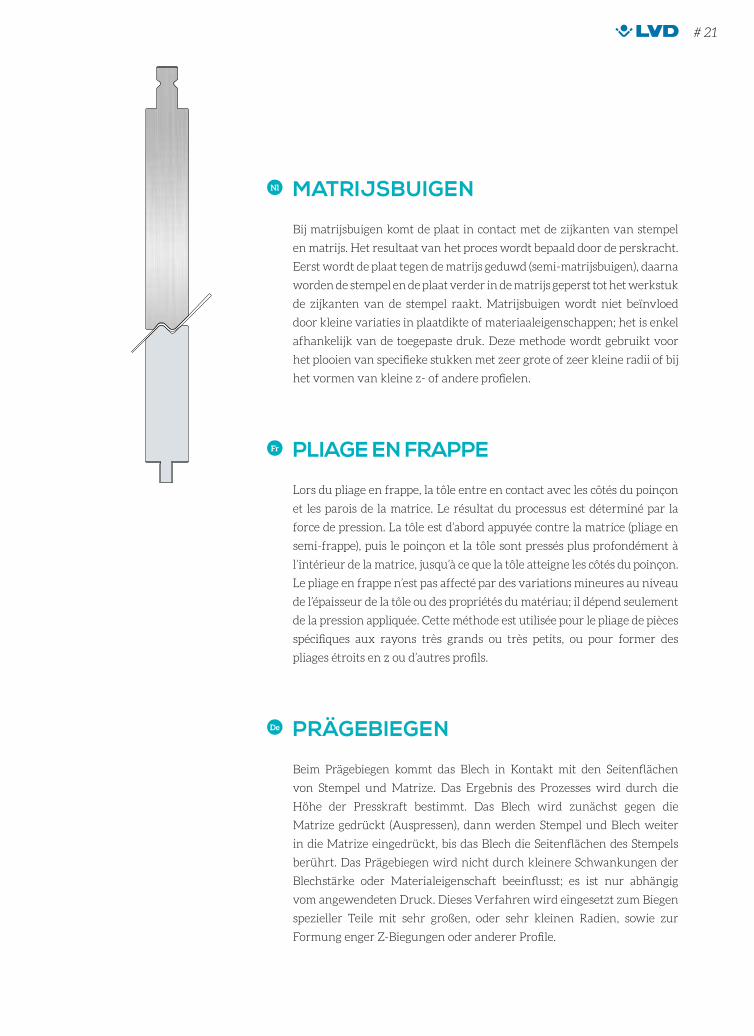
MATRIJSBUIGEN
Bij matrijsbuigen komt de plaat in contact met de zijkanten van stempel
en matrijs. Het resultaat van het proces wordt bepaald door de perskracht.
Eerst wordt de plaat tegen de matrijs geduwd (semi-matrijsbuigen), daarna
worden de stempel en de plaat verder in de matrijs geperst tot het werkstuk
de zijkanten van de stempel raakt. Matrijsbuigen wordt niet beïnvloed
door kleine variaties in plaatdikte of materiaaleigenschappen; het is enkel
afhankelijk van de toegepaste druk. Deze methode wordt gebruikt voor
het plooien van specifieke stukken met zeer grote of zeer kleine radii of bij
het vormen van kleine z- of andere profielen.
Nl
PLIAGE EN FRAPPE
Lors du pliage en frappe, la tôle entre en contact avec les côtés du poinçon
et les parois de la matrice. Le résultat du processus est déterminé par la
force de pression. La tôle est d’abord appuyée contre la matrice (pliage en
semi-frappe), puis le poinçon et la tôle sont pressés plus profondément à
l’intérieur de la matrice, jusqu’à ce que la tôle atteigne les côtés du poinçon.
Le pliage en frappe n’est pas affecté par des variations mineures au niveau
de l’épaisseur de la tôle ou des propriétés du matériau; il dépend seulement
de la pression appliquée. Cette méthode est utilisée pour le pliage de pièces
spécifiques aux rayons très grands ou très petits, ou pour former des
pliages étroits en z ou d’autres profils.
Fr
PRÄGEBIEGEN
Beim Prägebiegen kommt das Blech in Kontakt mit den Seitenflächen
von Stempel und Matrize. Das Ergebnis des Prozesses wird durch die
Höhe der Presskraft bestimmt. Das Blech wird zunächst gegen die
Matrize gedrückt (Auspressen), dann werden Stempel und Blech weiter
in die Matrize eingedrückt, bis das Blech die Seitenflächen des Stempels
berührt. Das Prägebiegen wird nicht durch kleinere Schwankungen der
Blechstärke oder Materialeigenschaft beeinflusst; es ist nur abhängig
vom angewendeten Druck. Dieses Verfahren wird eingesetzt zum Biegen
spezieller Teile mit sehr großen, oder sehr kleinen Radien, sowie zur
Formung enger Z-Biegungen oder anderer Profile.
De
COINING
# 21
CADMAN®-B SOFTWARE
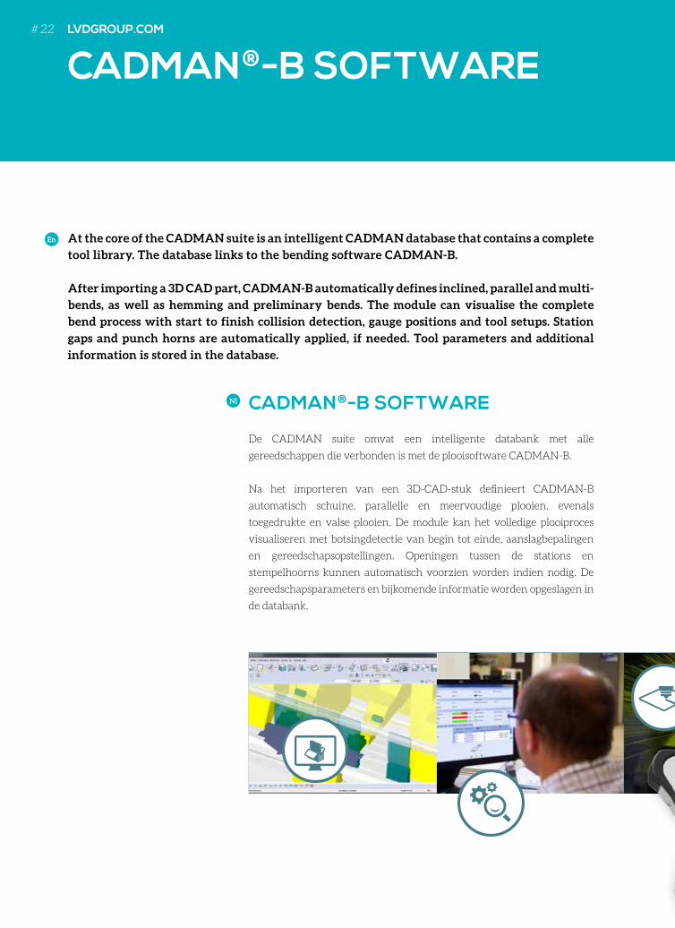
At the core of the CADMAN suite is an intelligent CADMAN database that contains a complete
tool library. The database links to the bending software CADMAN-B.
After importing a 3D CAD part, CADMAN-B automatically defines inclined, parallel and multi-
bends, as well as hemming and preliminary bends. The module can visualise the complete
bend process with start to finish collision detection, gauge positions and tool setups. Station
gaps and punch horns are automatically applied, if needed. Tool parameters and additional
information is stored in the database.
En
CADMAN®-B SOFTWARE
De CADMAN suite omvat een intelligente databank met alle
gereedschappen die verbonden is met de plooisoftware CADMAN-B.
Na het importeren van een 3D-CAD-stuk definieert CADMAN-B
automatisch schuine, parallelle en meervoudige plooien, evenals
toegedrukte en valse plooien. De module kan het volledige plooiproces
visualiseren met botsingdetectie van begin tot einde, aanslagbepalingen
en gereedschapsopstellingen. Openingen tussen de stations en
stempelhoorns kunnen automatisch voorzien worden indien nodig. De
gereedschapsparameters en bijkomende informatie worden opgeslagen in
de databank.
Nl
LVDGROUP.COM# 22
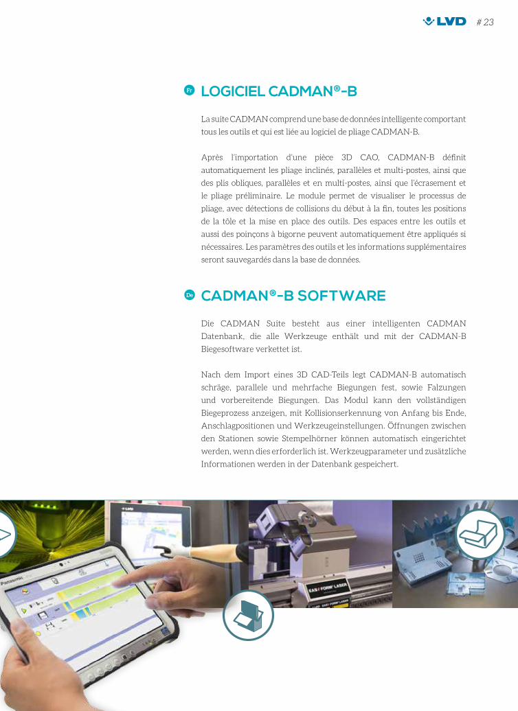
LOGICIEL CADMAN®-B
La suite CADMAN comprend une base de données intelligente comportant
tous les outils et qui est liée au logiciel de pliage CADMAN-B.
Après l’importation d’une pièce 3D CAO, CADMAN-B définit
automatiquement les pliage inclinés, parallèles et multi-postes, ainsi que
des plis obliques, parallèles et en multi-postes, ainsi que l’écrasement et
le pliage préliminaire. Le module permet de visualiser le processus de
pliage, avec détections de collisions du début à la fin, toutes les positions
de la tôle et la mise en place des outils. Des espaces entre les outils et
aussi des poinçons à bigorne peuvent automatiquement être appliqués si
nécessaires. Les paramètres des outils et les informations supplémentaires
seront sauvegardés dans la base de données.
Fr
CADMAN®-B SOFTWARE
Die CADMAN Suite besteht aus einer intelligenten CADMAN
Datenbank, die alle Werkzeuge enthält und mit der CADMAN-B
Biegesoftware verkettet ist.
Nach dem Import eines 3D CAD-Teils legt CADMAN-B automatisch
schräge, parallele und mehrfache Biegungen fest, sowie Falzungen
und vorbereitende Biegungen. Das Modul kann den vollständigen
Biegeprozess anzeigen, mit Kollisionserkennung von Anfang bis Ende,
Anschlagpositionen und Werkzeugeinstellungen. Öffnungen zwischen
den Stationen sowie Stempelhörner können automatisch eingerichtet
werden, wenn dies erforderlich ist. Werkzeugparameter und zusätzliche
Informationen werden in der Datenbank gespeichert.
De
# 23

FREE SPACE
FRE
E S
PA
CE
VRIJE RUIMTE ESPACE LIBREFREIRAUM
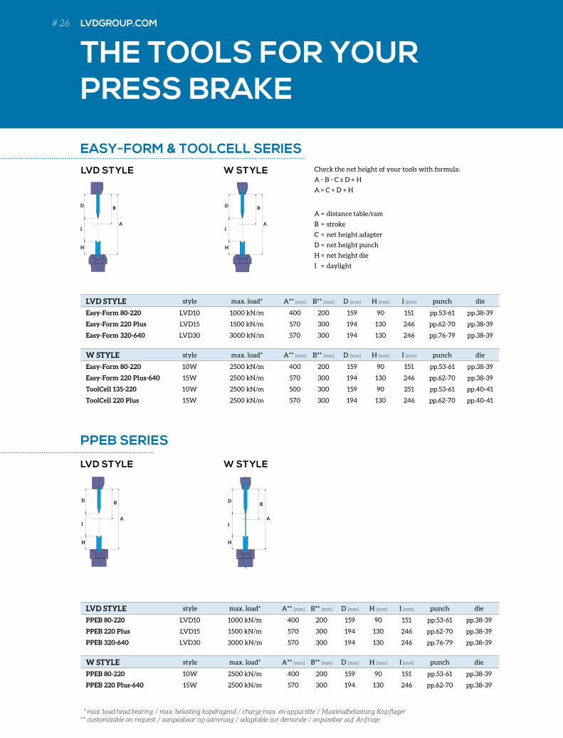
THE TOOLS FOR YOUR PRESS BRAKE
LVD STYLE style max. load* A** [mm] B** [mm] D [mm] H [mm] I [mm] punch die
Easy-Form 80-220 LVD10 1000 kN/m 400 200 159 90 151 pp.53-61 pp.38-39
Easy-Form 220 Plus LVD15 1500 kN/m 570 300 194 130 246 pp.62-70 pp.38-39
Easy-Form 320-640 LVD30 3000 kN/m 570 300 194 130 246 pp.76-79 pp.38-39
W STYLE style max. load* A** [mm] B** [mm] D [mm] H [mm] I [mm] punch die
Easy-Form 80-220 10W 2500 kN/m 400 200 159 90 151 pp.53-61 pp.38-39
Easy-Form 220 Plus-640 15W 2500 kN/m 570 300 194 130 246 pp.62-70 pp.38-39
ToolCell 135-220 10W 2500 kN/m 500 300 159 90 251 pp.53-61 pp.40-41
ToolCell 220 Plus 15W 2500 kN/m 570 300 194 130 246 pp.62-70 pp.40-41
LVD STYLE style max. load* A** [mm] B** [mm] D [mm] H [mm] I [mm] punch die
PPEB 80-220 LVD10 1000 kN/m 400 200 159 90 151 pp.53-61 pp.38-39
PPEB 220 Plus LVD15 1500 kN/m 570 300 194 130 246 pp.62-70 pp.38-39
PPEB 320-640 LVD30 3000 kN/m 570 300 194 130 246 pp.76-79 pp.38-39
W STYLE style max. load* A** [mm] B** [mm] D [mm] H [mm] I [mm] punch die
PPEB 80-220 10W 2500 kN/m 400 200 159 90 151 pp.53-61 pp.38-39
PPEB 220 Plus-640 15W 2500 kN/m 570 300 194 130 246 pp.62-70 pp.38-39
A
BD
I
H
A
BD
I
H
W STYLE
W STYLE
LVD STYLE
LVD STYLE
A
BD
I
H
EASY-FORM & TOOLCELL SERIES
PPEB SERIES
* max. load head bearing / max. belasting kopdragend / charge max. en appui tête / Maximalbelastung Kopflager** customizable on request / aanpasbaar op aanvraag / adaptable sur demande / anpassbar auf Anfrage
A
BD
I
H
A = distance table/ram
B = stroke
C = net height adapter
D = net height punch
H = net height die
I = daylight
Check the net height of your tools with formula:
A - B - C ≤ D + H
A > C + D + H
# 26 LVDGROUP.COM
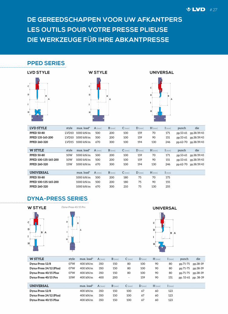
DE GEREEDSCHAPPEN VOOR UW AFKANTPERS
LES OUTILS POUR VOTRE PRESSE PLIEUSE
DIE WERKZEUGE FÜR IHRE ABKANTPRESSE
LVD STYLE style max. load* A [mm] B [mm] C [mm] D [mm] H [mm] I [mm] punch die
PPED 50-80 LVD10 1000 kN/m 500 200 100 159 70 171 pp.53-61 pp.38/39/43
PPED 135-165-200 LVD10 1000 kN/m 500 200 100 159 90 151 pp.53-61 pp.38/39/43
PPED 260-320 LVD15 1000 kN/m 670 300 100 194 130 246 pp.62-70 pp.38/39/43
W STYLE style max. load* A [mm] B [mm] C [mm] D [mm] H [mm] I [mm] punch die
PPED 50-80 10W 1000 kN/m 500 200 100 159 70 171 pp.53-61 pp.38/39/43
PPED 100-135-165-200 10W 1000 kN/m 500 200 100 159 90 151 pp.53-61 pp.38/39/43
PPED 260-320 15W 1000 kN/m 670 300 100 194 130 246 pp.62-70 pp.38/39/43
UNIVERSAL max. load* A [mm] B [mm] C [mm] D [mm] H [mm] I [mm]
PPED 50-80 1000 kN/m 500 200 180 75 70 175
PPED 100-135-165-200 1000 kN/m 500 200 180 75 90 155
PPED 260-320 1000 kN/m 670 300 210 75 130 255
W STYLE style max. load* A [mm] B [mm] C [mm] D [mm] H [mm] I [mm] punch die
Dyna-Press 12/8 07W 400 kN/m 350 150 80 100 90 80 pp.71-75 pp.38-39
Dyna-Press 24/12 (Plus) 07W 400 kN/m 350 150 80 100 90 80 pp.71-75 pp.38-39
Dyna-Press 40/15 Plus 07W 400 kN/m 350 150 80 100 90 80 pp.71-75 pp.38-39
Dyna-Press 40/15 Pro 10W 400 kN/m 400 200 - 159 90 151 pp. 53-61 pp. 38-39
UNIVERSAL max. load* A [mm] B [mm] C [mm] D [mm] H [mm] I [mm]
Dyna-Press 12/8 400 kN/m 350 150 100 67 60 123
Dyna-Press 24/12 (Plus) 400 kN/m 350 150 100 67 60 123
Dyna-Press 40/15 Plus 400 kN/m 350 150 100 67 60 123
UNIVERSALW STYLE
W STYLE UNIVERSALLVD STYLE
PPED SERIES
DYNA-PRESS SERIES
A
BD
C
I
H
B AD
C
I
H
A
BD
I
H
A
BD
C
I
H
B AD
C
I
H
A
BD
C
I
H
Dyna-Press 40/15 Pro
# 27
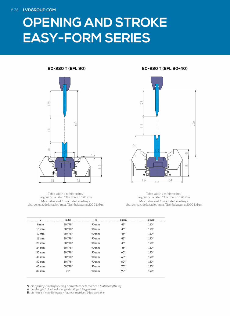
OPENING AND STROKE EASY-FORM SERIES
Table width / tafelbreedte / largeur de la table / Tischbreite: 120 mm
Max. table load / max. tafelbelasting / charge max. de la table / max. Tischbelastung: 2000 kN/m
Table width / tafelbreedte / largeur de la table / Tischbreite: 120 mm
Max. table load / max. tafelbelasting / charge max. de la table / max. Tischbelastung: 2000 kN/m
80-220 T (EFL 90) 80-220 T (EFL 90+40)
V die H min max
8 mm 30°/78° 90 mm 45° 150°
10 mm 30°/78° 90 mm 45° 150°
12 mm 30°/78° 90 mm 45° 150°
16 mm 30°/78° 90 mm 45° 150°
20 mm 30°/78° 90 mm 45° 150°
24 mm 30°/78° 90 mm 45° 150°
30 mm 30°/78° 90 mm 60° 150°
40 mm 30°/78° 90 mm 60° 150°
50 mm 30°/78° 90 mm 60° 150°
60 mm 60°/78° 90 mm 70° 150°
80 mm 78° 90 mm 90° 150°
V: die opening / matrijsopening / ouverture de la matrice / Matrizenöffnung: bend angle / plooihoek / angle de pliage / BiegewinkelH: die height / matrijshoogte / hauteur matrice / Matrizenhöhe
# 28 LVDGROUP.COM
OPENING AND STROKE EASY-FORM SERIES
OPENING EN SLAG EASY-FORM-REEKS
OUVERTURE ET COURSE SÉRIE EASY-FORM
ÖFFNUNG UND HUB EASY-FORM-REIHE
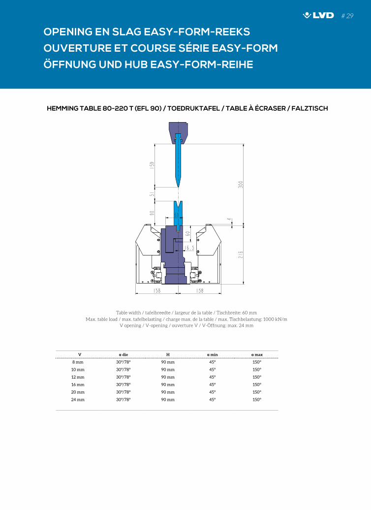
Table width / tafelbreedte / largeur de la table / Tischbreite: 60 mm
Max. table load / max. tafelbelasting / charge max. de la table / max. Tischbelastung: 1000 kN/m
V opening / V-opening / ouverture V / V-Öffnung: max. 24 mm
HEMMING TABLE 80-220 T (EFL 90) / TOEDRUKTAFEL / TABLE À ÉCRASER / FALZTISCH
V die H min max
8 mm 30°/78° 90 mm 45° 150°
10 mm 30°/78° 90 mm 45° 150°
12 mm 30°/78° 90 mm 45° 150°
16 mm 30°/78° 90 mm 45° 150°
20 mm 30°/78° 90 mm 45° 150°
24 mm 30°/78° 90 mm 45° 150°
# 29
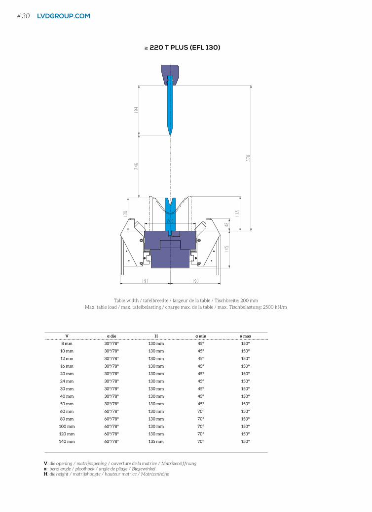
Table width / tafelbreedte / largeur de la table / Tischbreite: 200 mm
Max. table load / max. tafelbelasting / charge max. de la table / max. Tischbelastung: 2500 kN/m
≥ 220 T PLUS (EFL 130)
V die H min max
8 mm 30°/78° 130 mm 45° 150°
10 mm 30°/78° 130 mm 45° 150°
12 mm 30°/78° 130 mm 45° 150°
16 mm 30°/78° 130 mm 45° 150°
20 mm 30°/78° 130 mm 45° 150°
24 mm 30°/78° 130 mm 45° 150°
30 mm 30°/78° 130 mm 45° 150°
40 mm 30°/78° 130 mm 45° 150°
50 mm 30°/78° 130 mm 45° 150°
60 mm 60°/78° 130 mm 70° 150°
80 mm 60°/78° 130 mm 70° 150°
100 mm 60°/78° 130 mm 70° 150°
120 mm 60°/78° 130 mm 70° 150°
140 mm 60°/78° 135 mm 70° 150°
V: die opening / matrijsopening / ouverture de la matrice / Matrizenöffnung: bend angle / plooihoek / angle de pliage / BiegewinkelH: die height / matrijshoogte / hauteur matrice / Matrizenhöhe
# 30 LVDGROUP.COM
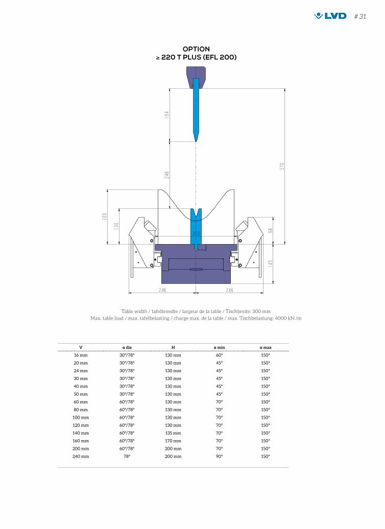
Table width / tafelbreedte / largeur de la table / Tischbreite: 300 mm
Max. table load / max. tafelbelasting / charge max. de la table / max. Tischbelastung: 4000 kN /m
OPTION≥ 220 T PLUS (EFL 200)
V die H min max
16 mm 30°/78° 130 mm 60° 150°
20 mm 30°/78° 130 mm 45° 150°
24 mm 30°/78° 130 mm 45° 150°
30 mm 30°/78° 130 mm 45° 150°
40 mm 30°/78° 130 mm 45° 150°
50 mm 30°/78° 130 mm 45° 150°
60 mm 60°/78° 130 mm 70° 150°
80 mm 60°/78° 130 mm 70° 150°
100 mm 60°/78° 130 mm 70° 150°
120 mm 60°/78° 130 mm 70° 150°
140 mm 60°/78° 135 mm 70° 150°
160 mm 60°/78° 170 mm 70° 150°
200 mm 60°/78° 200 mm 70° 150°
240 mm 78° 200 mm 90° 150°
# 31

# 32 LVDGROUP.COM
FIND OUT HOW WE’RE REDUCING WEAR AND EXPANDING HORIZONSSHELL TELLUS MAKES IT POSSIBLE
SHELL LUBRICANTSTOGETHER ANYTHING IS POSSIBLE
壳牌润滑油
携手共进成就无限可能!
SHELL LUBRICANTSTOGETHER ANYTHING IS POSSIBLE
LVD RECOMMENDS SHELL TELLUS
MATRIJZENMATRICESMATRIZEN
DIES DIE
S
FIND OUT HOW WE’RE REDUCING WEAR AND EXPANDING HORIZONSSHELL TELLUS MAKES IT POSSIBLE
SHELL LUBRICANTSTOGETHER ANYTHING IS POSSIBLE
壳牌润滑油
携手共进成就无限可能!
SHELL LUBRICANTSTOGETHER ANYTHING IS POSSIBLE
LVD RECOMMENDS SHELL TELLUS
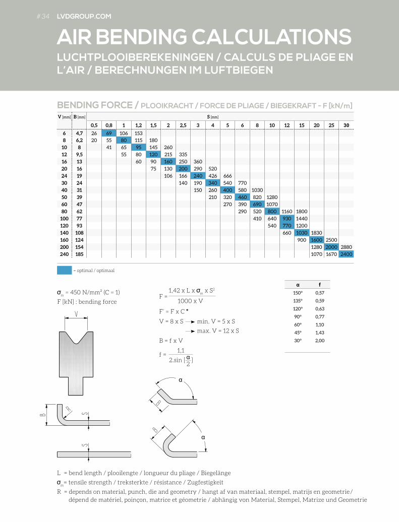
# 34 LVDGROUP.COM
V [mm] B [mm] S [mm]
0,5 0,8 1 1,2 1,5 2 2,5 3 4 5 6 8 10 12 15 20 25 30
6 4,7 26 69 106 153
8 6,2 20 55 80 115 180
10 8 41 65 95 145 260
12 9,5 55 80 120 215 335
16 13 60 90 160 250 360
20 16 75 130 200 290 520
24 19 106 166 240 426 666
30 24 140 190 340 540 770
40 31 150 260 400 580 1030
50 39 210 320 460 820 1280
60 47 270 390 690 1070
80 62 290 520 800 1160 1800
100 77 410 640 930 1440
120 93 540 770 1200
140 108 660 1030 1830
160 124 900 1600 2500
200 154 1280 2000 2880
240 185 1070 1670 2400
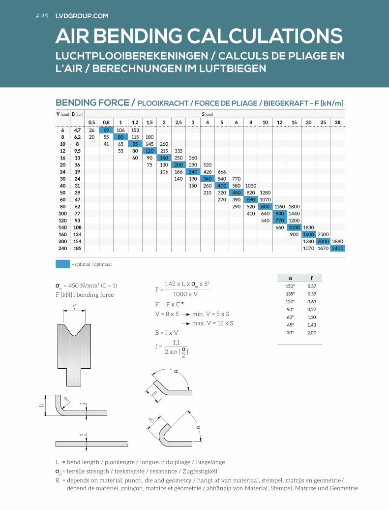
BENDING FORCE / PLOOIKRACHT / FORCE DE PLIAGE / BIEGEKRAFT - F [kN/m]
= optimal / optimaal
m = 450 N/mm² (C = 1)
F [kN] : bending force
L = bend length / plooilengte / longueur du pliage / Biegelänge
m= tensile strength / treksterkte / résistance / Zugfestigkeit
R = depends on material, punch, die and geometry / hangt af van materiaal, stempel, matrijs en geometrie/ dépend de matériel, poinçon, matrice et géometrie / abhängig von Material, Stempel, Matrize und Geometrie
B = f x V
f
150° 0,57
135° 0,59
120° 0,63
90° 0,77
60° 1,10
45° 1,43
30° 2,00
F = 1,42 x L x
m x S2
1000 x V
V = 8 x S min. V = 5 x S
max. V = 12 x S
F’ = F x C *
f = 1,1
22.sin [ ]
LUCHTPLOOIBEREKENINGEN / CALCULS DE PLIAGE EN L’AIR / BERECHNUNGEN IM LUFTBIEGEN
AIR BENDING CALCULATIONS
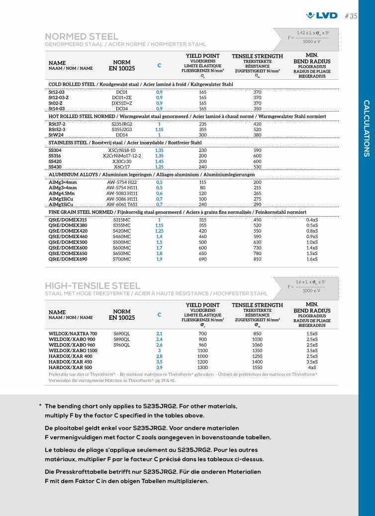
* The bending chart only applies to S235JRG2. For other materials,
multiply F by the factor C specified in the tables above.
De plooitabel geldt enkel voor S235JRG2. Voor andere materialen
F vermenigvuldigen met factor C zoals aangegeven in bovenstaande tabellen.
Le tableau de pliage s’applique seulement au S235JRG2. Pour les autres
matériaux, multiplier F par le facteur C précisé dans les tableaux ci-dessus.
Die Presskrafttabelle betrifft nur S235JRG2. Für die anderen Materialien
F mit dem Faktor C in den obigen Tabellen multiplizieren.
NAMENAAM / NOM / NAME
NORMEN 10025 C
YIELD POINT VLOEIGRENS
LIMITE ÉLASTIQUEFLIESSGRENZE N/mm²
e
TENSILE STRENGTHTREKSTERKTE
RÉSISTANCEZUGFESTIGKEIT N/mm²
m
MIN. BEND RADIUS
PLOOIRADIUSRADIUS DE PLIAGE
BIEGERADIUS
COLD ROLLED STEEL / Koudgewalst staal / Acier laminé à froid / Kaltgewalzter Stahl
St12-03 DC01 0,9 165 370St12-03-Z DC01+ZE 0,9 165 370St02-Z DX51D+Z 0,9 165 370St14-03 DC04 0,9 165 350
HOT ROLLED STEEL NORMED / Warmgewalst staal genormeerd / Acier laminé à chaud normé / Warmgewalzter Stahl normiert
RSt37-2 S235JRG2 1 235 420RSt52-3 S355J2G3 1,15 355 520StW24 DD14 1 300 380
STAINLESS STEEL / Roestvrij staal / Acier inoxydable / Rostfreier Stahl
SS304 X5CrNi18-10 1,35 230 590SS316 X2CrNiMo17-12-2 1,35 200 600SS420 X30Cr30 1,45 200 600SS430 X6Cr17 1,25 240 530
ALUMINIUM ALLOYS / Aluminium legeringen / Alliages aluminium / Aluminiumlegierungen
AlMg3<4mm AW-5754 H22 0,5 115 200AlMg3>4mm AW-5754 H111 0,5 80 215AlMg4.5Mn AW-5083 H111 0,6 120 265AlMg1SiCu AW-5086 H111 0,7 100 275AlMg1SiCu AW-6061 T651 0,7 240 290
FINE GRAIN STEEL NORMED / Fijnkorrelig staal genormeerd / Aciers à grains fins normalisés / Feinkornstahl normiert
QStE/DOMEX315 S315MC 1 315 450 0.4xSQStE/DOMEX380 S355MC 1,15 355 520 0.5xSQStE/DOMEX420 S420MC 1,25 420 550 0.8xSQStE/DOMEX460 S460MC 1,4 460 590 0.9xSQStE/DOMEX500 S500MC 1,5 500 630 1.0xSQStE/DOMEX600 S600MC 1,7 600 730 1.4xSQStE/DOMEX650 S650MC 1,8 650 780 1.5xSQStE/DOMEX690 S700MC 1,9 690 810 1.6xS
NAMENAAM / NOM / NAME
NORMEN 10025 C
YIELD POINT VLOEIGRENS
LIMITE ÉLASTIQUEFLIESSGRENZE N/mm²
se
TENSILE STRENGTHTREKSTERKTE
RÉSISTANCEZUGFESTIGKEIT N/mm²
sm
MIN. BEND RADIUS
PLOOIRADIUSRADIUS DE PLIAGE
BIEGERADIUS
WELDOX/NAXTRA 700 S690QL 2,1 700 850 1.5xSWELDOX/XABO 900 S890QL 2,4 900 1030 2.5xSWELDOX/XABO 960 S960QL 2,6 960 1060 2.5xSWELDOX/XABO 1100 3 1100 1350 3.5xSHARDOX/XAR 400 2,8 1000 1250 2.5xSHARDOX/XAR 450 3,5 1200 1400 3.5xSHARDOX/XAR 500 3,9 1300 1550 4xS
Preferably use dies in Thyrotherm®. - Bij voorkeur matrijzen in Thyrotherm® gebruiken. - Utilisez de préférences des matrices en Thyrotherm®. Verwenden Sie vorzugsweise Matrizen in Thyrotherm®: pg 39 & 41.
NORMED STEELGENORMEERD STAAL / ACIER NORMÉ / NORMIERTER STAHL
HIGH-TENSILE STEELSTAAL MET HOGE TREKSTERKTE / ACIER À HAUTE RÉSISTANCE / HOCHFESTER STAHL
F = 1,42 x L x
m x S2
1000 x V
F = 1,6 x L x
m x S2
1000 x V
CA
LCU
LAT
ION
S# 35
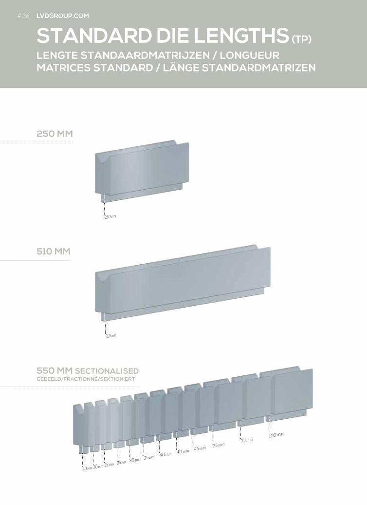
LENGTE STANDAARDMATRIJZEN / LONGUEUR MATRICES STANDARD / LÄNGE STANDARDMATRIZEN
STANDARD DIE LENGTHS (TP)
250 MM
550 MM SECTIONALISEDGEDEELD/FRACTIONNÉ/SEKTIONIERT
510 MM
120 mm
20 mm 20 mm 25 mm 25 mm 30 mm 35 mm 40 mm 40 mm 45 mm 75 mm75 mm
510 mm
250 mm
# 36 LVDGROUP.COM

LENGTE TOOLCELL-MATRIJZEN / LONGUEUR MATRICES TOOLCELL / LÄNGE TOOLCELL-MATRIZEN
TOOLCELL DIE LENGTHS (TC)
480 MM SECTIONALISEDGEDEELD/FRACTIONNÉ/SEKTIONIERT
420 MM SECTIONALISEDGEDEELD/FRACTIONNÉ/SEKTIONIERT
20 mm 25 mm 25 mm 30 mm 30 mm 35 mm35 mm
40 mm40 mm
45 mm45 mm
50 mm
120 mm
120 mm
120 mm
120 mm
# 37
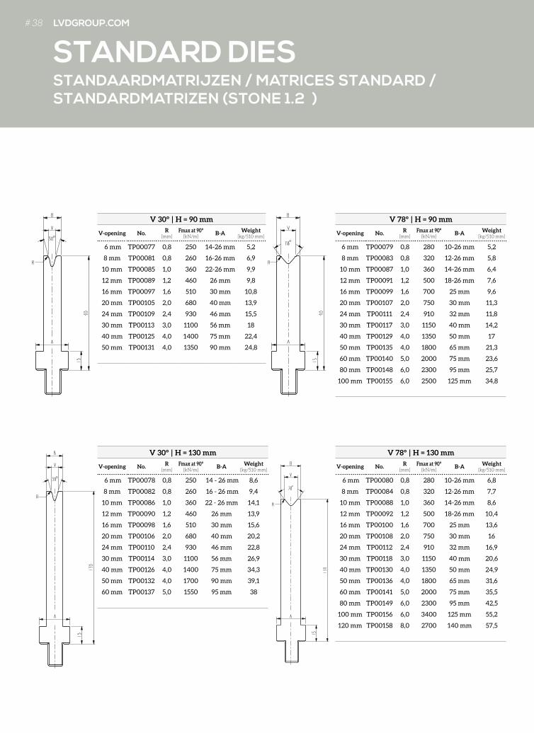
STANDAARDMATRIJZEN / MATRICES STANDARD / STANDARDMATRIZEN (STONE 1.2 )
STANDARD DIES
V 30° | H = 90 mm
V-opening No. R [mm]
Fmax at 90° [kN/m]
B-A Weight [kg/510 mm]
6 mm TP00077 0,8 250 14-26 mm 5,2
8 mm TP00081 0,8 260 16-26 mm 6,9
10 mm TP00085 1,0 360 22-26 mm 9,9
12 mm TP00089 1,2 460 26 mm 9,8
16 mm TP00097 1,6 510 30 mm 10,8
20 mm TP00105 2,0 680 40 mm 13,9
24 mm TP00109 2,4 930 46 mm 15,5
30 mm TP00113 3,0 1100 56 mm 18
40 mm TP00125 4,0 1400 75 mm 22,4
50 mm TP00131 4,0 1350 90 mm 24,8
V 30° | H = 130 mm
V-opening No. R[mm]
Fmax at 90° [kN/m]
B-A Weight [kg/510 mm]
6 mm TP00078 0,8 250 14 - 26 mm 8,6
8 mm TP00082 0,8 260 16 - 26 mm 9,4
10 mm TP00086 1,0 360 22 - 26 mm 14,1
12 mm TP00090 1,2 460 26 mm 13,9
16 mm TP00098 1,6 510 30 mm 15,6
20 mm TP00106 2,0 680 40 mm 20,2
24 mm TP00110 2,4 930 46 mm 22,8
30 mm TP00114 3,0 1100 56 mm 26,9
40 mm TP00126 4,0 1400 75 mm 34,3
50 mm TP00132 4,0 1700 90 mm 39,1
60 mm TP00137 5,0 1550 95 mm 38
V 78° | H = 90 mm
V-opening No. R[mm]
Fmax at 90° [kN/m]
B-A Weight [kg/510 mm]
6 mm TP00079 0,8 280 10-26 mm 5,2
8 mm TP00083 0,8 320 12-26 mm 5,8
10 mm TP00087 1,0 360 14-26 mm 6,4
12 mm TP00091 1,2 500 18-26 mm 7,6
16 mm TP00099 1,6 700 25 mm 9,6
20 mm TP00107 2,0 750 30 mm 11,3
24 mm TP00111 2,4 910 32 mm 11,8
30 mm TP00117 3,0 1150 40 mm 14,2
40 mm TP00129 4,0 1350 50 mm 17
50 mm TP00135 4,0 1800 65 mm 21,3
60 mm TP00140 5,0 2000 75 mm 23,6
80 mm TP00148 6,0 2300 95 mm 25,7
100 mm TP00155 6,0 2500 125 mm 34,8
V 78° | H = 130 mm
V-opening No. R[mm]
Fmax at 90° [kN/m]
B-A Weight [kg/510 mm]
6 mm TP00080 0,8 280 10-26 mm 6,8
8 mm TP00084 0,8 320 12-26 mm 7,7
10 mm TP00088 1,0 360 14-26 mm 8,6
12 mm TP00092 1,2 500 18-26 mm 10,4
16 mm TP00100 1,6 700 25 mm 13,6
20 mm TP00108 2,0 750 30 mm 16
24 mm TP00112 2,4 910 32 mm 16,9
30 mm TP00118 3,0 1150 40 mm 20,6
40 mm TP00130 4,0 1350 50 mm 24,9
50 mm TP00136 4,0 1800 65 mm 31,6
60 mm TP00141 5,0 2000 75 mm 35,5
80 mm TP00149 6,0 2300 95 mm 42,5
100 mm TP00156 6,0 3400 125 mm 55,2
120 mm TP00158 8,0 2700 140 mm 57,5
# 38 LVDGROUP.COM
MATRIJZEN 60° / MATRICES 60° / V-MATRIZEN 60°(STONE 1.2)
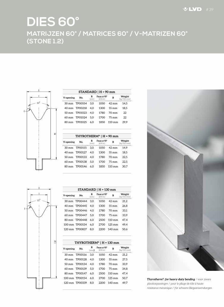
DIES 60°# 39
STANDARD | H = 90 mm
V-opening No. R [mm]
Fmax at 90° [kN/m]
B Weight [kg/510 mm]
30 mm TP00554 3,0 1050 42 mm 14,5
40 mm TP00218 4,0 1300 55 mm 18,5
50 mm TP01023 4,0 1780 70 mm 22
60 mm TP01024 5,0 1700 75 mm 22
80 mm TP01025 6,0 1850 110 mm 29,9
STANDARD | H = 130 mm
V-opening No. R [mm]
Fmax at 90° [kN/m]
B Weight [kg/510 mm]
30 mm TP00444 3,0 1050 42 mm 21,2
40 mm TP00445 4,0 1300 55 mm 26,8
50 mm TP00446 4,0 1780 70 mm 33,1
60 mm TP00447 5,0 1700 75 mm 33,9
80 mm TP00448 6,0 2500 110 mm 47,4
100 mm TP00534 6,0 2700 125 mm 49,4
120 mm TP00837 8,0 2200 140 mm 50,6
Thyrotherm®: for heavy-duty bending / voor zware
plooitoepassingen / pour le pliage de tôle à haute
résistance mécanique / für schwere Biegeanwendungen
THYROTHERM® | H = 90 mm
V-opening No. R [mm]
Fmax at 90° [kN/m]
B Weight [kg/510 mm]
30 mm TP00115 3,0 1050 42 mm 14,9
40 mm TP00127 4,0 1300 55 mm 18,5
50 mm TP00133 4,0 1780 70 mm 22,5
60 mm TP00138 5,0 1700 75 mm 22,5
80 mm TP00146 6,0 1850 110 mm 30,7
THYROTHERM® | H = 130 mm
V-opening No.R
[mm])Fmax at 90°
[kN/m]B Weight
[kg/510 mm]
30 mm TP00116 3,0 1050 42 mm 21,2
40 mm TP00128 4,0 1300 55 mm 27,5
50 mm TP00134 4,0 1780 70 mm 33,9
60 mm TP00139 5,0 1700 75 mm 34,8
80 mm TP00147 6,0 2500 110 mm 47,4
100 mm TP00154 6,0 2700 125 mm 50,7
120 mm TP00339 8,0 2200 140 mm 49,7
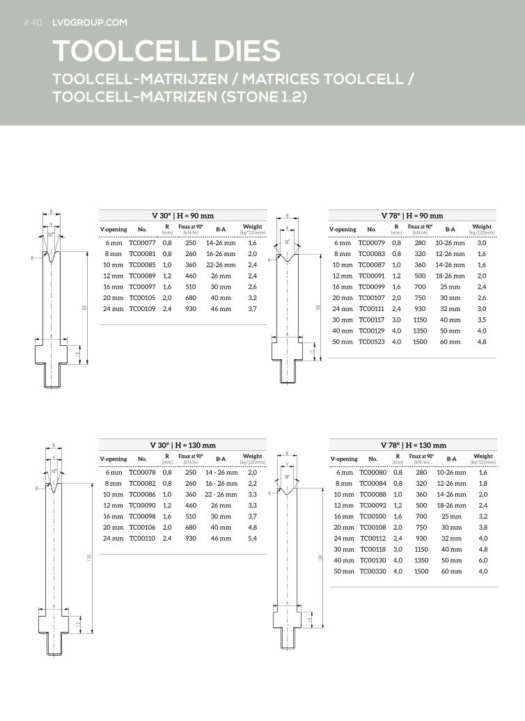
V 30° | H = 90 mm
V-opening No. R[mm]
Fmax at 90° [kN/m]
B-A Weight [kg/120mm]
6 mm TC00077 0,8 250 14-26 mm 1,6
8 mm TC00081 0,8 260 16-26 mm 2,0
10 mm TC00085 1,0 360 22-26 mm 2,4
12 mm TC00089 1,2 460 26 mm 2,4
16 mm TC00097 1,6 510 30 mm 2,6
20 mm TC00105 2,0 680 40 mm 3,2
24 mm TC00109 2,4 930 46 mm 3,7
V 78° | H = 90 mm
V-opening No. R[mm]
Fmax at 90° [kN/m]
B-A Weight [kg/120mm]
6 mm TC00079 0,8 280 10-26 mm 3,0
8 mm TC00083 0,8 320 12-26 mm 1,6
10 mm TC00087 1,0 360 14-26 mm 1,6
12 mm TC00091 1,2 500 18-26 mm 2,0
16 mm TC00099 1,6 700 25 mm 2,4
20 mm TC00107 2,0 750 30 mm 2,6
24 mm TC00111 2,4 930 32 mm 3,0
30 mm TC00117 3,0 1150 40 mm 3,5
40 mm TC00129 4,0 1350 50 mm 4,0
50 mm TC00523 4,0 1500 60 mm 4,8
V 30° | H = 130 mm
V-opening No. R[mm]
Fmax at 90° [kN/m]
B-A Weight [kg/120mm]
6 mm TC00078 0,8 250 14 - 26 mm 2,0
8 mm TC00082 0,8 260 16 - 26 mm 2,2
10 mm TC00086 1,0 360 22 - 26 mm 3,3
12 mm TC00090 1,2 460 26 mm 3,3
16 mm TC00098 1,6 510 30 mm 3,7
20 mm TC00106 2,0 680 40 mm 4,8
24 mm TC00110 2,4 930 46 mm 5,4
V 78° | H = 130 mm
V-opening No. R[mm]
Fmax at 90° [kN/m]
B-A Weight [kg/120mm]
6 mm TC00080 0,8 280 10-26 mm 1,6
8 mm TC00084 0,8 320 12-26 mm 1,8
10 mm TC00088 1,0 360 14-26 mm 2,0
12 mm TC00092 1,2 500 18-26 mm 2,4
16 mm TC00100 1,6 700 25 mm 3,2
20 mm TC00108 2,0 750 30 mm 3,8
24 mm TC00112 2,4 930 32 mm 4,0
30 mm TC00118 3,0 1150 40 mm 4,8
40 mm TC00130 4,0 1350 50 mm 6,0
50 mm TC00330 4,0 1500 60 mm 4,0
TOOLCELL-MATRIJZEN / MATRICES TOOLCELL / TOOLCELL-MATRIZEN (STONE 1.2)
TOOLCELL DIES# 40 LVDGROUP.COM
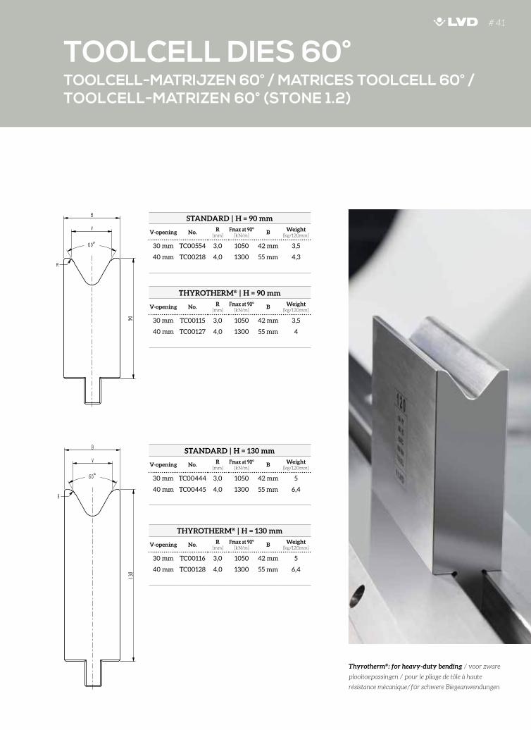
# 41
STANDARD | H = 90 mm
V-opening No. R[mm]
Fmax at 90° [kN/m]
B Weight [kg/120mm]
30 mm TC00554 3,0 1050 42 mm 3,5
40 mm TC00218 4,0 1300 55 mm 4,3
STANDARD | H = 130 mm
V-opening No. R[mm]
Fmax at 90° [kN/m]
B Weight [kg/120mm]
30 mm TC00444 3,0 1050 42 mm 5
40 mm TC00445 4,0 1300 55 mm 6,4
TOOLCELL-MATRIJZEN 60° / MATRICES TOOLCELL 60° / TOOLCELL-MATRIZEN 60° (STONE 1.2)
TOOLCELL DIES 60°
Thyrotherm®: for heavy-duty bending / voor zware
plooitoepassingen / pour le pliage de tôle à haute
résistance mécanique/für schwere Biegeanwendungen
THYROTHERM® | H = 90 mm
V-opening No. R[mm]
Fmax at 90° [kN/m]
B Weight [kg/120mm]
30 mm TC00115 3,0 1050 42 mm 3,5
40 mm TC00127 4,0 1300 55 mm 4
THYROTHERM® | H = 130 mm
V-opening No. R[mm]
Fmax at 90° [kN/m]
B Weight [kg/120mm]
30 mm TC00116 3,0 1050 42 mm 5
40 mm TC00128 4,0 1300 55 mm 6,4
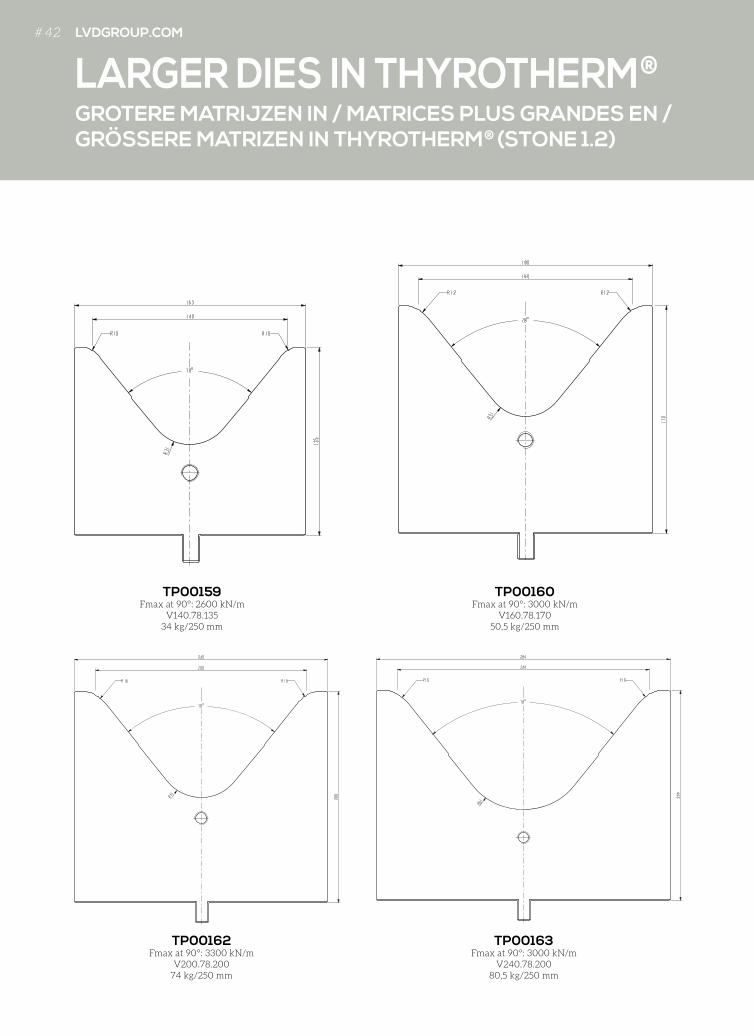
GROTERE MATRIJZEN IN / MATRICES PLUS GRANDES EN / GRÖSSERE MATRIZEN IN THYROTHERM® (STONE 1.2)
LARGER DIES IN THYROTHERM®
TP00159Fmax at 90°: 2600 kN/m
V140.78.13534 kg/250 mm
TP00162Fmax at 90°: 3300 kN/m
V200.78.20074 kg/250 mm
TP00160Fmax at 90°: 3000 kN/m
V160.78.17050,5 kg/250 mm
TP00163Fmax at 90°: 3000 kN/m
V240.78.20080,5 kg/250 mm
# 42 LVDGROUP.COM
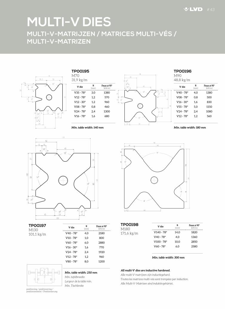
V dieR
[mm]Fmax at 90°
[kN/m]
V35 - 78° 3,0 1380
V12 - 78° 1,2 570
V12 - 30° 1,2 960
V08 - 78° 0,8 460
V24 - 78° 2,4 1300
V16 - 78° 1,6 680
V dieR
[mm]Fmax at 90°
[kN/m]
V40 - 78° 4,0 1380
V08 - 78° 0,8 500
V16 - 30° 1,6 830
V55 - 78° 5,0 1150
V24 - 78° 2,4 1080
V12 - 78° 1,2 560
MULTI-V-MATRIJZEN / MATRICES MULTI-VÉS / MULTI-V-MATRIZEN
MULTI-V DIES
TP00195M7031,9 kg/m
V dieR
[mm]Fmax at 90°
[kN/m]
V40 - 78° 4,0 2180
V10 - 78° 1,0 800
V60 - 78° 6,0 2880
V16 - 30° 1,6 770
V24 - 78° 2,4 1920
V12 - 78° 1,2 960
V80 - 78° 8,0 1200
TP00197M130101,1 kg/m
TP00196M9048,8 kg/m
V dieR
[mm]Fmax at 90°
[kN/m]
V140 - 78° 14,0 1820
V40 - 78° 4,0 1360
V100 - 78° 10,0 2850
V60 - 78° 6,0 2580
TP00198M180171,6 kg/m
All multi-V dies are inductive hardened.
Alle multi-V matrijzen zijn inductiegehard.
Toutes les matrices multi-vés sont trempées par induction.
Alle Multi-V-Matrizen sind induktivgehärtet.
Min. table width: 140 mm
Min. table width: 250 mm
Min. tafelbreedte
Largeur de la table min.
Min. Tischbreite
Min. table width: 300 mm
Min. table width: 180 mm
positioning / positionering /positionnement / Positionierung
# 43
VERSTELBARE MATRIJZEN / MATRICES RÉGLABLES / VERSTELLBARE MATRIZEN
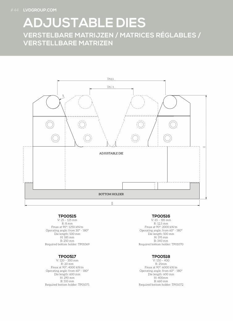
ADJUSTABLE DIES
TP00515V: 25 – 125 mm
R: 8 mmFmax at 90°: 1250 kN/m
Operating angle: from 30° - 180°Die length: 500 mm
H: 185 mmB: 250 mm
Required bottom holder: TP01069
TP00518V: 150 – 400
R: 25mmFmax at 90°: 6000 kN/m
Operating angle: from 60° - 180°Die length: 600 mm
H: 400mmB: 660 mm
Required bottom holder: TP01072
TP00516V: 65 – 185 mm
R: 12,5 mmFmax at 90°: 2000 kN/m
Operating angle: from 60° - 180°Die length: 500 mm
H: 195 mm B: 340 mm
Required bottom holder: TP01070
TP00517V: 120 – 300 mm
R: 20 mmFmax at 90°: 4000 kN/m
Operating angle: from 60° - 180°Die length: 600 mm
H: 290 mmB: 510 mm
Required bottom holder: TP01071
ADJUSTABLE DIE
BOTTOM HOLDER
# 44 LVDGROUP.COM
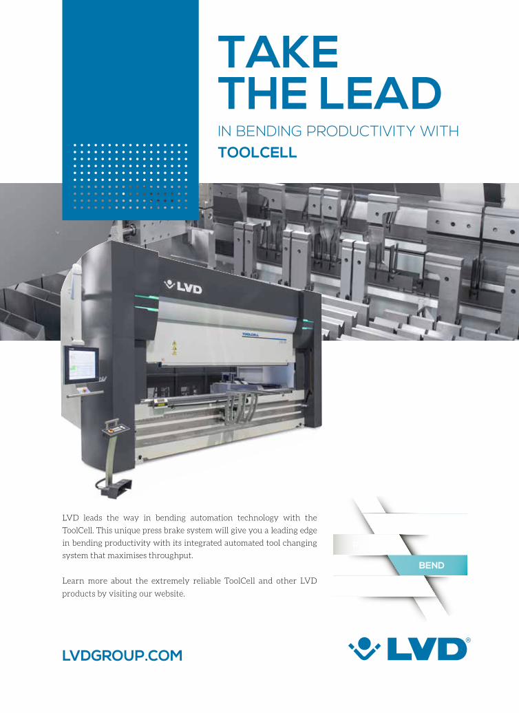
TAKE THE LEAD IN BENDING PRODUCTIVITY WITH TOOLCELL
LASER
PUNCH
INTEGRATE
BEND
LVDGROUP.COM
LVD leads the way in bending automation technology with the
ToolCell. This unique press brake system will give you a leading edge
in bending productivity with its integrated automated tool changing
system that maximises throughput.
Learn more about the extremely reliable ToolCell and other LVD
products by visiting our website.
# 45
Press Brake Buyer’s Guide showcases industry leading press brake manufacturers and machine models incorporating the very latest in embedded performance technology.
In each issue we present the latest press brake
models, news and product releases including our
valued Platinum Plus partner LVD.
Visit our website to download the latest issue
and learn how LVD makes Smart Manufacturing
possible with highly efficient and flexible sheet
metal working products.
4900
LA
Z-LV
DTE
YOUR GUIDE TO THE LATEST PRESS BRAKE TECHNOLOGY.www.pressbrakebuyersguide.com
Your Guide to the Latest Press Brake Technology
PU
NC
HE
S
STEMPELSPOINÇONSSTEMPEL
PUNCHES
# 48 LVDGROUP.COM
V [mm] B [mm] S [mm]
0,5 0,8 1 1,2 1,5 2 2,5 3 4 5 6 8 10 12 15 20 25 30
6 4,7 26 69 106 153
8 6,2 20 55 80 115 180
10 8 41 65 95 145 260
12 9,5 55 80 120 215 335
16 13 60 90 160 250 360
20 16 75 130 200 290 520
24 19 106 166 240 426 666
30 24 140 190 340 540 770
40 31 150 260 400 580 1030
50 39 210 320 460 820 1280
60 47 270 390 690 1070
80 62 290 520 800 1160 1800
100 77 410 640 930 1440
120 93 540 770 1200
140 108 660 1030 1830
160 124 900 1600 2500
200 154 1280 2000 2880
240 185 1070 1670 2400
BENDING FORCE / PLOOIKRACHT / FORCE DE PLIAGE / BIEGEKRAFT - F [kN/m]
= optimal / optimaal
m = 450 N/mm² (C = 1)
F [kN] : bending force
L = bend length / plooilengte / longueur du pliage / Biegelänge
m= tensile strength / treksterkte / résistance / Zugfestigkeit
R = depends on material, punch, die and geometry / hangt af van materiaal, stempel, matrijs en geometrie/ dépend de matériel, poinçon, matrice et géometrie / abhängig von Material, Stempel, Matrize und Geometrie
B = f x V
f
150° 0,57
135° 0,59
120° 0,63
90° 0,77
60° 1,10
45° 1,43
30° 2,00
F = 1,42 x L x
m x S2
1000 x V
V = 8 x S min. V = 5 x S
max. V = 12 x S
F’ = F x C *
f = 1,1
22.sin [ ]
LUCHTPLOOIBEREKENINGEN / CALCULS DE PLIAGE EN L’AIR / BERECHNUNGEN IM LUFTBIEGEN
AIR BENDING CALCULATIONS

NAMENAAM / NOM / NAME
NORMEN 10025 C
YIELD POINT VLOEIGRENS
LIMITE ÉLASTIQUEFLIESSGRENZE N/mm²
e
TENSILE STRENGTHTREKSTERKTE
RÉSISTANCEZUGFESTIGKEIT N/mm²
m
MIN. BEND RADIUS
PLOOIRADIUSRADIUS DE PLIAGE
BIEGERADIUS
COLD ROLLED STEEL / Koudgewalst staal / Acier laminé à froid / Kaltgewalzter Stahl
St12-03 DC01 0,9 165 370St12-03-Z DC01+ZE 0,9 165 370St02-Z DX51D+Z 0,9 165 370St14-03 DC04 0,9 165 350
HOT ROLLED STEEL NORMED / Warmgewalst staal genormeerd / Acier laminé à chaud normé / Warmgewalzter Stahl normiert
RSt37-2 S235JRG2 1 235 420RSt52-3 S355J2G3 1,15 355 520StW24 DD14 1 300 380
STAINLESS STEEL / Roestvrij staal / Acier inoxydable / Rostfreier Stahl
SS304 X5CrNi18-10 1,35 230 590SS316 X2CrNiMo17-12-2 1,35 200 600SS420 X30Cr30 1,45 200 600SS430 X6Cr17 1,25 240 530
ALUMINIUM ALLOYS / Aluminium legeringen / Alliages aluminium / Aluminiumlegierungen
AlMg3<4mm AW-5754 H22 0,5 115 200AlMg3>4mm AW-5754 H111 0,5 80 215AlMg4.5Mn AW-5083 H111 0,6 120 265AlMg1SiCu AW-5086 H111 0,7 100 275AlMg1SiCu AW-6061 T651 0,7 240 290
FINE GRAIN STEEL NORMED / Fijnkorrelig staal genormeerd / Aciers à grains fins normalisés / Feinkornstahl normiert
QStE/DOMEX315 S315MC 1 315 450 0.4xSQStE/DOMEX380 S355MC 1,15 355 520 0.5xSQStE/DOMEX420 S420MC 1,25 420 550 0.8xSQStE/DOMEX460 S460MC 1,4 460 590 0.9xSQStE/DOMEX500 S500MC 1,5 500 630 1.0xSQStE/DOMEX600 S600MC 1,7 600 730 1.4xSQStE/DOMEX650 S650MC 1,8 650 780 1.5xSQStE/DOMEX690 S700MC 1,9 690 810 1.6xS
NAMENAAM / NOM / NAME
NORMEN 10025 C
YIELD POINT VLOEIGRENS
LIMITE ÉLASTIQUEFLIESSGRENZE N/mm²
se
TENSILE STRENGTHTREKSTERKTE
RÉSISTANCEZUGFESTIGKEIT N/mm²
sm
MIN. BEND RADIUS
PLOOIRADIUSRADIUS DE PLIAGE
BIEGERADIUS
WELDOX/NAXTRA 700 S690QL 2,1 700 850 1.5xSWELDOX/XABO 900 S890QL 2,4 900 1030 2.5xSWELDOX/XABO 960 S960QL 2,6 960 1060 2.5xSWELDOX/XABO 1100 3 1100 1350 3.5xSHARDOX/XAR 400 2,8 1000 1250 2.5xSHARDOX/XAR 450 3,5 1200 1400 3.5xSHARDOX/XAR 500 3,9 1300 1550 4xS
Preferably use dies in Thyrotherm®. - Bij voorkeur matrijzen in Thyrotherm® gebruiken. - Utilisez de préférences des matrices en Thyrotherm®. Verwenden Sie vorzugsweise Matrizen in Thyrotherm®: pg 39 & 41.
NORMED STEELGENORMEERD STAAL / ACIER NORMÉ / NORMIERTER STAHL
HIGH-TENSILE STEELSTAAL MET HOGE TREKSTERKTE / ACIER À HAUTE RÉSISTANCE / HOCHFESTER STAHL
F = 1,42 x L x
m x S2
1000 x V
F = 1,6 x L x
m x S2
1000 x V
CA
LCU
LAT
ION
S# 49
* The bending chart only applies to S235JRG2. For other materials,
multiply F by the factor C specified in the tables above.
De plooitabel geldt enkel voor S235JRG2. Voor andere materialen
F vermenigvuldigen met factor C zoals aangegeven in bovenstaande tabellen.
Le tableau de pliage s’applique seulement au S235JRG2. Pour les autres
matériaux, multiplier F par le facteur C précisé dans les tableaux ci-dessus.
Die Presskrafttabelle betrifft nur S235JRG2. Für die anderen Materialien
F mit dem Faktor C in den obigen Tabellen multiplizieren.
# 49
LENGTE STANDAARDSTEMPELS / LONGUEUR POINÇONS STANDARD / LÄNGE STANDARDSTEMPEL
250 MM
510 MM
550 MM SECTIONALISEDGEDEELD/FRACTIONNÉ/SEKTIONIERT
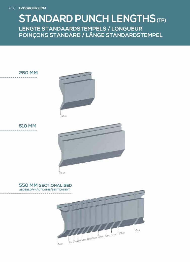
STANDARD PUNCH LENGTHS (TP)
75 mm
510 mm
250 mm
20 mm 20 mm 25 mm 25 mm 30 mm 35 mm 40 mm 40 mm 45 mm 120 mm75 mm
# 50 LVDGROUP.COM
LENGTE TOOLCELL-STEMPELS / LONGUEUR POINÇONS TOOLCELL / LÄNGE TOOLCELL-STEMPEL
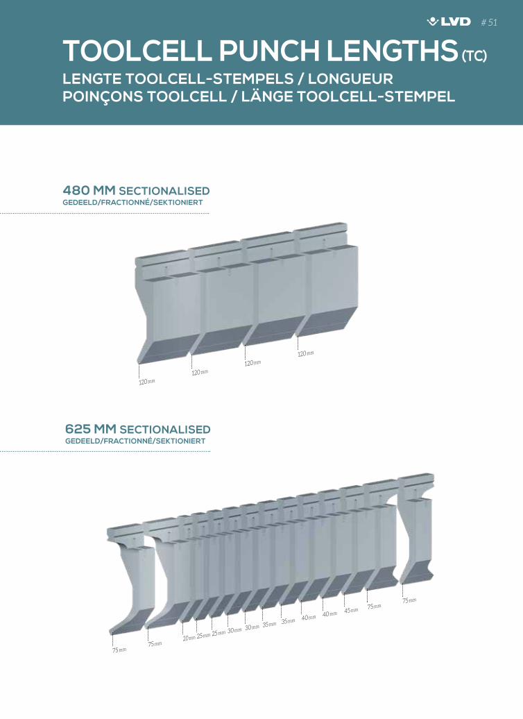
TOOLCELL PUNCH LENGTHS (TC)
480 MM SECTIONALISEDGEDEELD/FRACTIONNÉ/SEKTIONIERT
625 MM SECTIONALISEDGEDEELD/FRACTIONNÉ/SEKTIONIERT
120 mm
120 mm
120 mm
120 mm
75 mm75 mm
20 mm 25 mm 25 mm 30 mm 30 mm 35 mm 35 mm 40 mm 40 mm 45 mm 75 mm75 mm
# 51
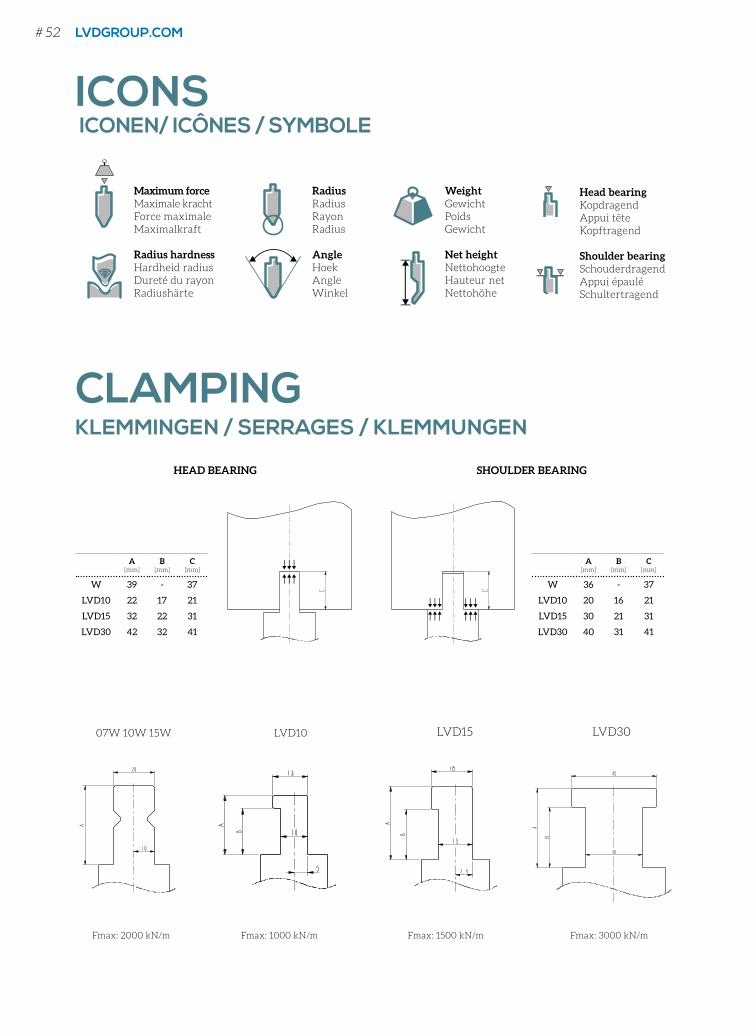
Maximum forceMaximale krachtForce maximaleMaximalkraft
Radius hardnessHardheid radiusDureté du rayonRadiushärte
WeightGewichtPoidsGewicht
Net heightNettohoogteHauteur netNettohöhe
RadiusRadiusRayonRadius
AngleHoekAngleWinkel
Head bearingKopdragendAppui têteKopftragend
Shoulder bearingSchouderdragend Appui épauléSchultertragend
ICONS ICONEN/ ICÔNES / SYMBOLE
CLAMPING KLEMMINGEN / SERRAGES / KLEMMUNGEN
A[mm]
B[mm]
C[mm]
W 39 - 37
LVD10 22 17 21
LVD15 32 22 31
LVD30 42 32 41
A[mm]
B[mm]
C[mm]
W 36 - 37
LVD10 20 16 21
LVD15 30 21 31
LVD30 40 31 41
HEAD BEARING SHOULDER BEARING
07W 10W 15W
Fmax: 2000 kN/m Fmax: 1500 kN/m Fmax: 3000 kN/m
LVD15 LVD30LVD10
Fmax: 1000 kN/m
# 52 LVDGROUP.COM
Head bearingKopdragendAppui têteKopftragend
Shoulder bearingSchouderdragend Appui épauléSchultertragend
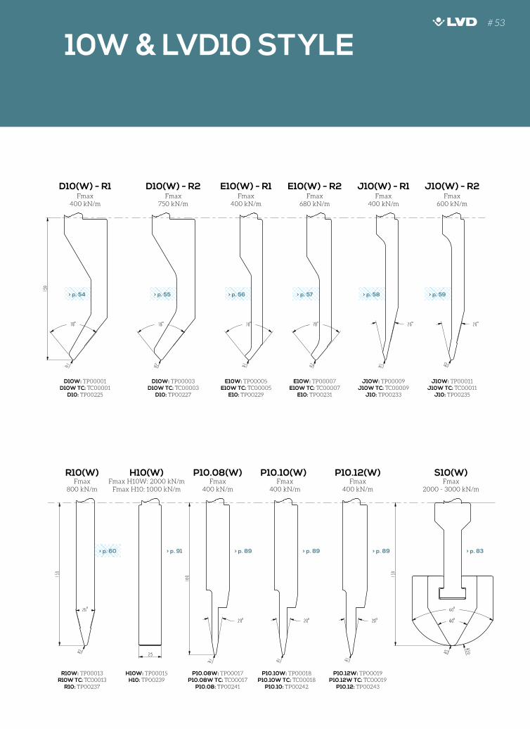
Fmax800 kN/m
Fmax H10W: 2000 kN/mFmax H10: 1000 kN/m
Fmax400 kN/m
Fmax400 kN/m
Fmax400 kN/m
Fmax2000 - 3000 kN/m
R10(W) H10(W) P10.08(W) P10.10(W) P10.12(W) S10(W)
R10W: TP00013R10W TC: TC00013
R10: TP00237
H10W: TP00015H10: TP00239
P10.08W: TP00017P10.08W TC: TC00017
P10.08: TP00241
P10.10W: TP00018P10.10W TC: TC00018
P10.10: TP00242
P10.12W: TP00019P10.12W TC: TC00019
P10.12: TP00243
Fmax400 kN/m
Fmax750 kN/m
Fmax400 kN/m
Fmax680 kN/m
Fmax400 kN/m
Fmax600 kN/m
D10(W) - R1 D10(W) - R2 E10(W) - R1 J10(W) - R1E10(W) - R2 J10(W) - R2
D10W: TP00001D10W TC: TC00001
D10: TP00225
D10W: TP00003D10W TC: TC00003
D10: TP00227
E10W: TP00005E10W TC: TC00005
E10: TP00229
E10W: TP00007E10W TC: TC00007
E10: TP00231
J10W: TP00009J10W TC: TC00009
J10: TP00233
J10W: TP00011J10W TC: TC00011
J10: TP00235
130
120
110
100
90
80
70
60
50
40
30
20
10
10
20
30
40
50
60
70
80
90
0
40
30
20
10
110
100
90
80
70
60
50
40
30
20
10
10
20
30
40
50
60
70
80
90
100
110
120
130
90
100
110
88°
130
120
110
100
90
80
70
60
50
40
30
20
10
10
20
30
40
50
60
70
80
90
0
40
30
20
10
110
100
90
80
70
60
50
40
30
20
10
10
20
30
40
50
60
70
80
90
100
110
120
130
90
100
110
88°
130
120
110
100
90
80
70
60
50
40
30
20
10
10
20
30
40
50
60
70
80
90
0
40
30
20
10
110
100
90
80
70
60
50
40
30
20
10
10
20
30
40
50
60
70
80
90
100
110
120
130
90
100
110
88°
130
120
110
100
90
80
70
60
50
40
30
20
10
10
20
30
40
50
60
70
80
90
0
40
30
20
10
110
100
90
80
70
60
50
40
30
20
1010
20
30
40
50
60
70
80
90
100
110
120
130
90
100
110
88°
130
120
110
100
90
80
70
60
50
40
30
20
1010
20
30
40
50
60
70
80
90
0
40
30
20
10
110
100
90
80
70
60
50
40
30
20
10
10
20
30
40
50
60
70
80
90
100
110
120
130
90
100
110
88°
130
120
110
100
90
80
70
60
50
40
30
20
10
10
20
30
40
50
60
70
80
90
0
40
30
20
10
110
100
90
80
70
60
50
40
30
20
10
10
20
30
40
50
60
70
80
90
100
110
120
130
90
100
110
88°
> p. 54 > p. 55 > p. 56 > p. 57 > p. 58 > p. 59
130
120
110
100
90
80
70
60
50
40
30
20
1010
20
30
40
50
60
70
80
90
0
40
30
20
10
110
100
90
80
70
60
50
40
30
20
10
10
20
30
40
50
60
70
80
90
100
110
120
130
90
100
110
88°
> p. 60 > p. 83> p. 89> p. 89> p. 89> p. 91
10W & LVD10 STYLE# 53
130
120
110
100
90
80
70
60
50
40
30
20
10
100
90
10
20
30
40
10
20
30
40
50
60
70
80
90
100
0
90
80
70
60
50
40
30
20
10
10
20
30
40
50
60
70
80
90
100
110
120
130
88°
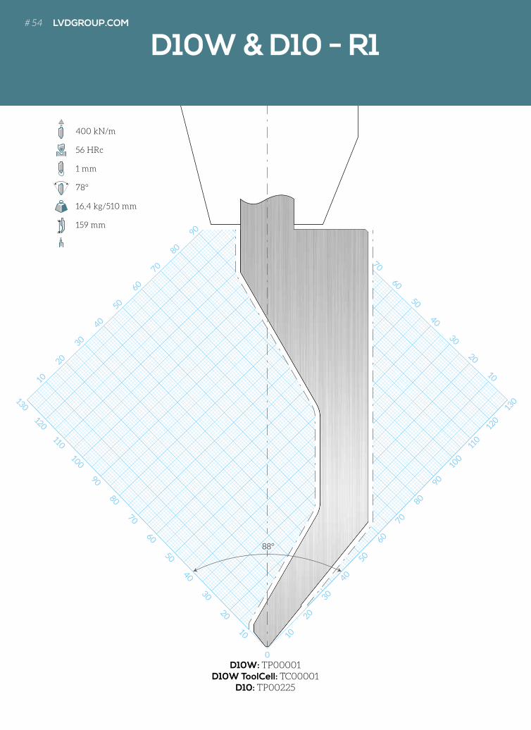
D10W & D10 - R1
D10W: TP00001D10W ToolCell: TC00001
D10: TP00225
400 kN/m
56 HRc
1 mm
78°
16,4 kg/510 mm
159 mm
# 54 LVDGROUP.COM
130
120
110
100
90
80
70
60
50
40
30
20
10
100
90
10
20
30
40
10
20
30
40
50
60
70
80
90
100
0
90
80
70
60
50
40
30
20
10
10
20
30
40
50
60
70
80
90
100
110
120
130
88°
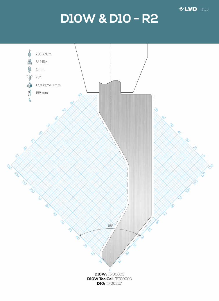
D10W & D10 - R1 D10W & D10 - R2
D10W: TP00003D10W ToolCell: TC00003
D10: TP00227
750 kN/m
56 HRc
2 mm
78°
17,8 kg/510 mm
159 mm
# 55
130
120
110
100
90
80
70
60
50
40
30
20
10 10
10
20
30
40
50
60
70
80
90
100
0
90
80
70
60
50
40
30
20
10
10
20
30
40
50
60
70
80
90
100
110
120
130
88°
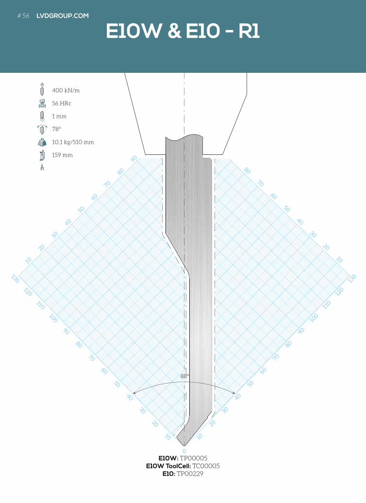
E10W: TP00005E10W ToolCell: TC00005
E10: TP00229
400 kN/m
56 HRc
1 mm
78°
10,1 kg/510 mm
159 mm
E10W & E10 - R1# 56 LVDGROUP.COM
130
120
110
100
90
80
70
60
50
40
30
20
10 10
10
20
30
40
50
60
70
80
90
100
0
90
80
70
60
50
40
30
20
10
10
20
30
40
50
60
70
80
90
100
110
120
130
88°
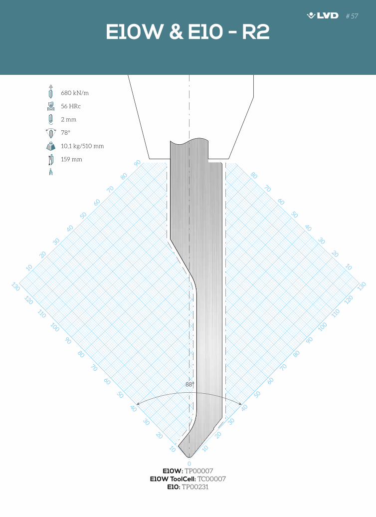
E10W: TP00007E10W ToolCell: TC00007
E10: TP00231
680 kN/m
56 HRc
2 mm
78°
10,1 kg/510 mm
159 mm
E10W & E10 - R1 E10W & E10 - R2# 57
130
120
110
100
90
80
70
60
50
40
30
20
10 10
10
20
30
40
50
60
70
80
90
100
0
90
80
70
60
50
40
30
20
10
10
20
30
40
50
60
70
80
90
100
110
120
130
88°
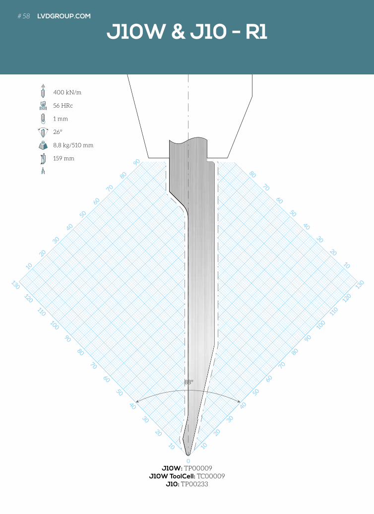
J10W: TP00009J10W ToolCell: TC00009
J10: TP00233
400 kN/m
56 HRc
1 mm
26°
8,8 kg/510 mm
159 mm
J10W & J10 - R1# 58 LVDGROUP.COM
130
120
110
100
90
80
70
60
50
40
30
20
10 10
10
20
30
40
50
60
70
80
90
100
0
90
80
70
60
50
40
30
20
10
10
20
30
40
50
60
70
80
90
100
110
120
130
88°
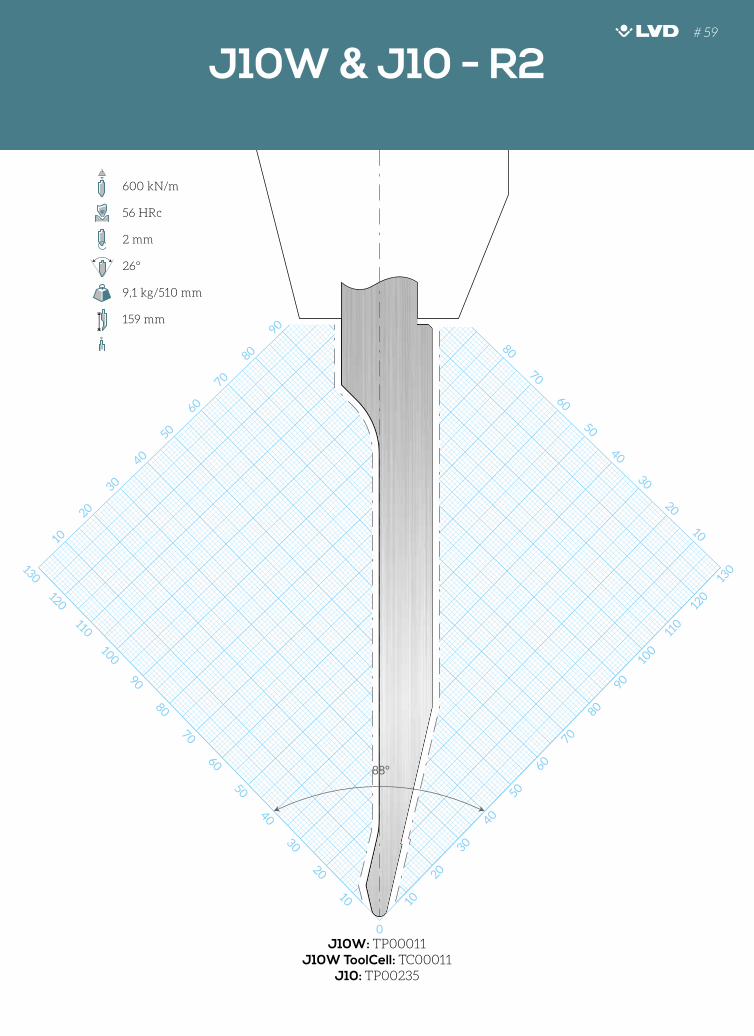
J10W: TP00011J10W ToolCell: TC00011
J10: TP00235
600 kN/m
56 HRc
2 mm
26°
9,1 kg/510 mm
159 mm
J10W & J10 - R1 J10W & J10 - R2# 59
130
120
110
100
90
80
70
60
50
40
30
20
10 10
10
20
30
40
50
60
70
80
90
100
0
100
90
80
70
60
50
40
30
20
10
10
20
30
40
50
60
70
80
90
100
110
120
130
88°
R10W & R10 - R2
R10W: TP00013R10W ToolCell: TC00013
R10: TP00237
800 kN/m
56 HRc
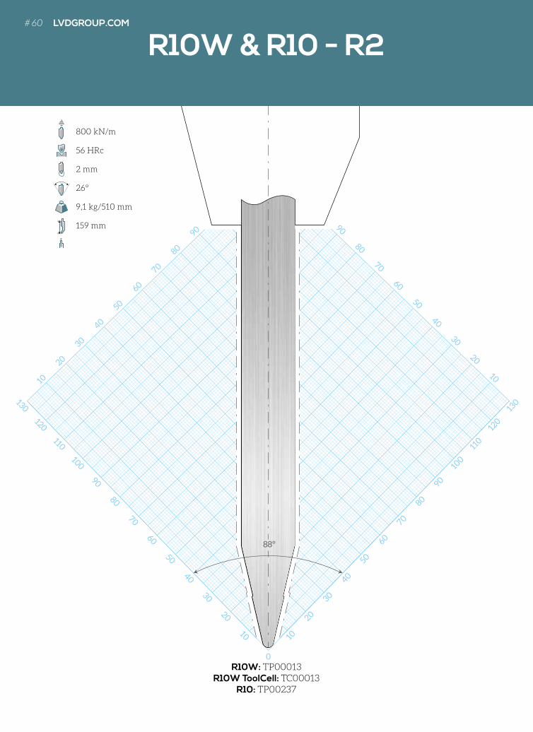
2 mm
26°
9,1 kg/510 mm
159 mm
# 60 LVDGROUP.COM
10 20 30 40 50 60 70 80
200
190
180
170
160
150
140
130
120
110
100
90
80
70
60
50
40
30
20
10
R10W & R10 - R210W & LVD10 HOORNS / BIGORNES / HORNSTÜCKE
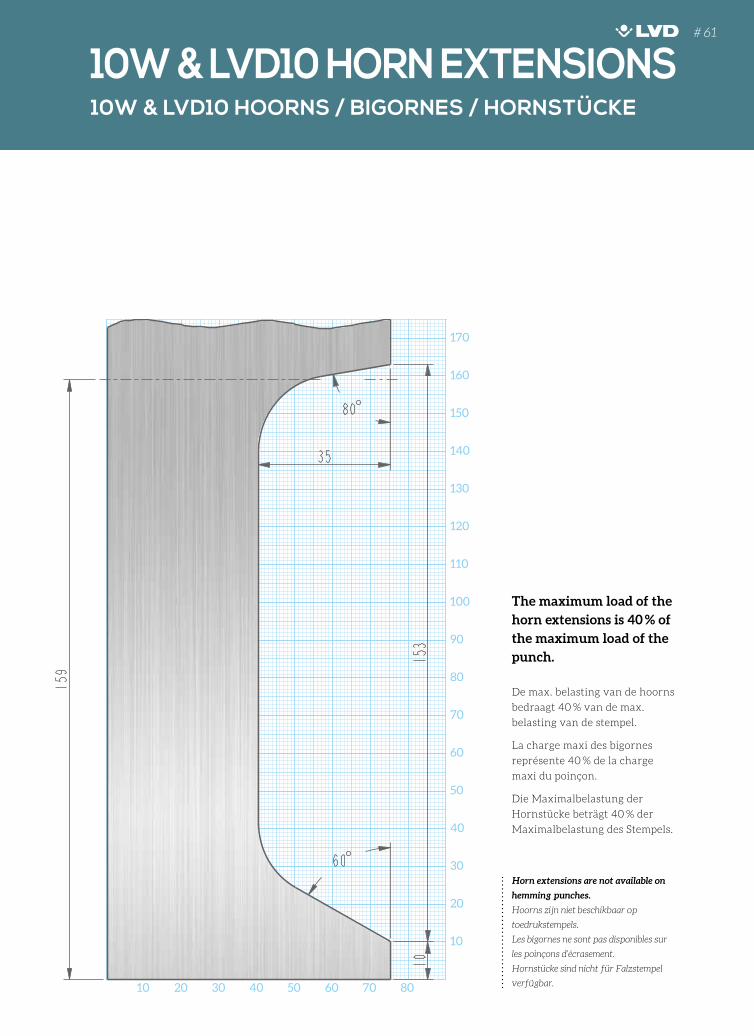
10W & LVD10 HORN EXTENSIONS
The maximum load of the
horn extensions is 40 % of
the maximum load of the
punch.
De max. belasting van de hoorns
bedraagt 40 % van de max.
belasting van de stempel.
La charge maxi des bigornes
représente 40 % de la charge
maxi du poinçon.
Die Maximalbelastung der
Hornstücke beträgt 40 % der
Maximalbelastung des Stempels.
Horn extensions are not available on
hemming punches.
Hoorns zijn niet beschikbaar op
toedrukstempels.
Les bigornes ne sont pas disponibles sur
les poinçons d’écrasement.
Hornstücke sind nicht für Falzstempel
verfügbar.
# 61
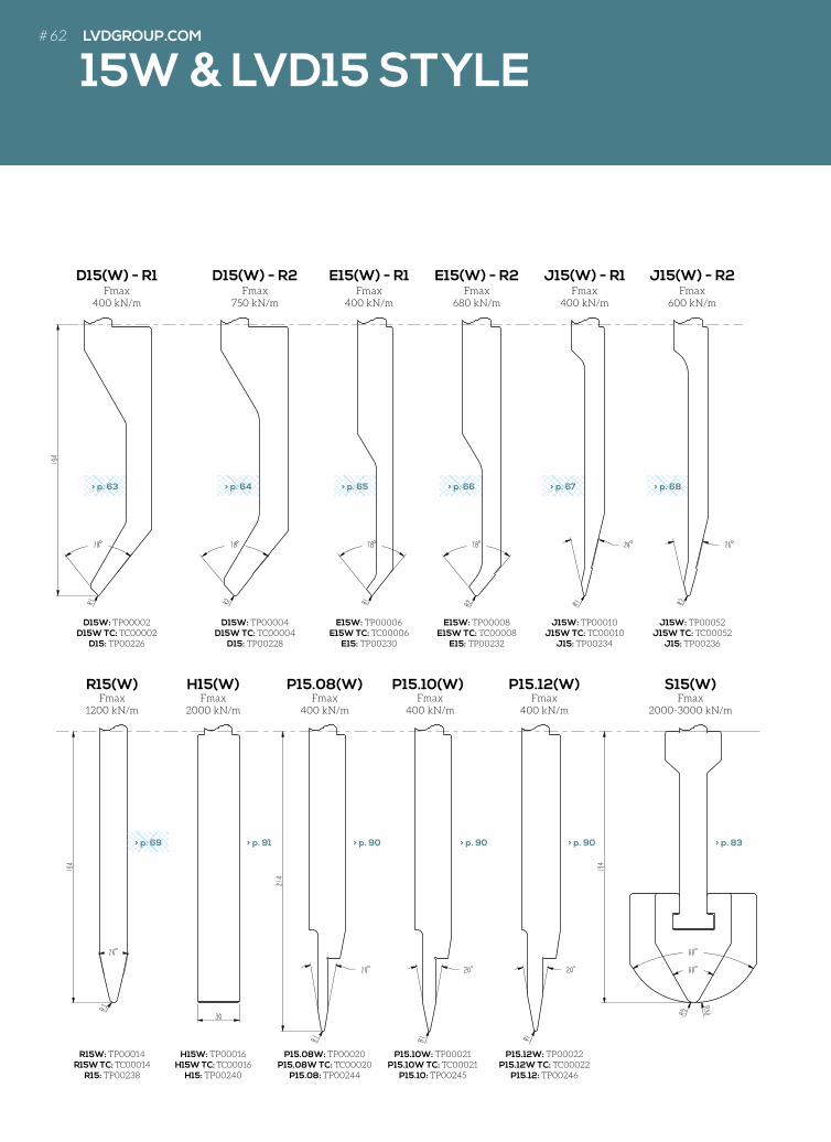
Fmax1200 kN/m
Fmax 2000 kN/m
Fmax400 kN/m
Fmax400 kN/m
Fmax400 kN/m
Fmax2000-3000 kN/m
R15(W) H15(W) P15.08(W) P15.10(W) P15.12(W) S15(W)
R15W: TP00014R15W TC: TC00014
R15: TP00238
H15W: TP00016H15W TC: TC00016
H15: TP00240
P15.08W: TP00020P15.08W TC: TC00020
P15.08: TP00244
P15.10W: TP00021P15.10W TC: TC00021
P15.10: TP00245
P15.12W: TP00022P15.12W TC: TC00022
P15.12: TP00246
Fmax400 kN/m
Fmax750 kN/m
Fmax400 kN/m
Fmax680 kN/m
Fmax400 kN/m
Fmax600 kN/m
D15(W) - R1 D15(W) - R2 E15(W) - R1 J15(W) - R1E15(W) - R2 J15(W) - R2
D15W: TP00002D15W TC: TC00002
D15: TP00226
D15W: TP00004D15W TC: TC00004
D15: TP00228
E15W: TP00006E15W TC: TC00006
E15: TP00230
E15W: TP00008E15W TC: TC00008
E15: TP00232
J15W: TP00010J15W TC: TC00010
J15: TP00234
J15W: TP00052J15W TC: TC00052
J15: TP00236
130
120
110
100
90
80
70
60
50
40
30
20
10
10
20
30
40
50
60
70
80
90
0
40
30
20
10
110
100
90
80
70
60
50
40
30
20
10
10
20
30
40
50
60
70
80
90
100
110
120
130
90
100
110
88°
130
120
110
100
90
80
70
60
50
40
30
20
10
10
20
30
40
50
60
70
80
90
0
40
30
20
10
110
100
90
80
70
60
50
40
30
20
10
10
20
30
40
50
60
70
80
90
100
110
120
130
90
100
110
88°
130
120
110
100
90
80
70
60
50
40
30
20
10
10
20
30
40
50
60
70
80
90
0
40
30
20
10
110
100
90
80
70
60
50
40
30
20
10
10
20
30
40
50
60
70
80
90
100
110
120
130
90
100
110
88°
130
120
110
100
90
80
70
60
50
40
30
20
10
10
20
30
40
50
60
70
80
90
0
40
30
20
10
110
100
90
80
70
60
50
40
30
20
10
10
20
30
40
50
60
70
80
90
100
110
120
130
90
100
110
88°
130
120
110
100
90
80
70
60
50
40
30
20
1010
20
30
40
50
60
70
80
90
0
40
30
20
10
110
100
90
80
70
60
50
40
30
20
10
10
20
30
40
50
60
70
80
90
100
110
120
130
90
100
110
88°
130
120
110
100
90
80
70
60
50
40
30
20
10
10
20
30
40
50
60
70
80
90
0
40
30
20
10
110
100
90
80
70
60
50
40
30
20
10
10
20
30
40
50
60
70
80
90
100
110
120
130
90
100
110
88°
> p. 63 > p. 64 > p. 65 > p. 66 > p. 67 > p. 68
130
120
110
100
90
80
70
60
50
40
30
20
10
10
20
30
40
50
60
70
80
90
0
40
30
20
10
110
100
90
80
70
60
50
40
30
20
10
10
20
30
40
50
60
70
80
90
100
110
120
130
90
100
110
88°
> p. 69 > p. 83
15W & LVD15 STYLE
> p. 90> p. 90> p. 90> p. 91
# 62 LVDGROUP.COM
130
120
110
100
90
80
70
60
50
40
30
20
10
130
120
110
100
90
10
20
30
40
10
20
30
40
50
60
70
80
90
100
110
120
130
0
90
80
70
60
50
40
30
20
10
10
20
30
40
50
60
70
80
90
100
110
120
130
88°
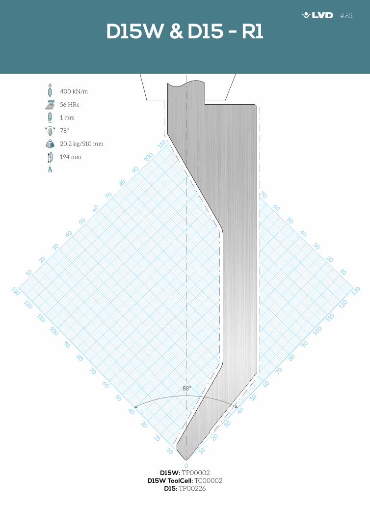
D15W: TP00002D15W ToolCell: TC00002
D15: TP00226
400 kN/m
56 HRc
1 mm
78°
20,2 kg/510 mm
194 mm
D15W & D15 - R1# 63
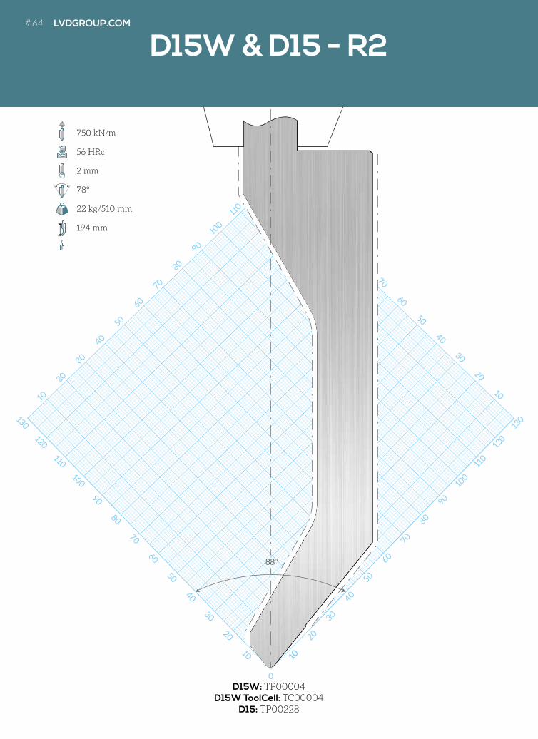
130
120
110
100
90
80
70
60
50
40
30
20
10
130
120
110
100
90
10
20
30
40
10
20
30
40
50
60
70
80
90
100
110
120
130
0
90
80
70
60
50
40
30
20
10
10
20
30
40
50
60
70
80
90
100
110
120
130
88°
10
D15W: TP00004D15W ToolCell: TC00004
D15: TP00228
750 kN/m
56 HRc
2 mm
78°
22 kg/510 mm
194 mm
D15W & D15 - R2# 64 LVDGROUP.COM
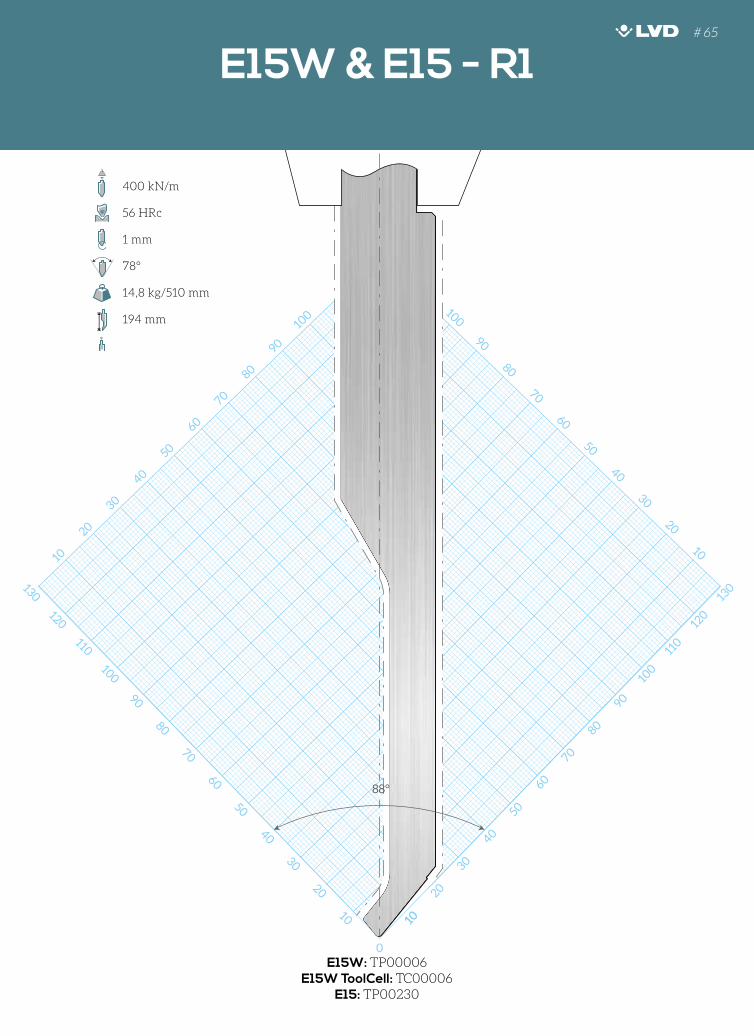
130
120
110
100
90
80
70
60
50
40
30
20
10
130
120
110
10
20
10
20
30
40
50
60
70
80
90
100
110
120
130
0
120
110
100
90
80
70
60
50
40
30
20
10
10
20
30
40
50
60
70
80
90
100
110
120
130
88°
10
E15W: TP00006E15W ToolCell: TC00006
E15: TP00230
400 kN/m
56 HRc
1 mm
78°
14,8 kg/510 mm
194 mm
D15W & D15 - R2 E15W & E15 - R1# 65
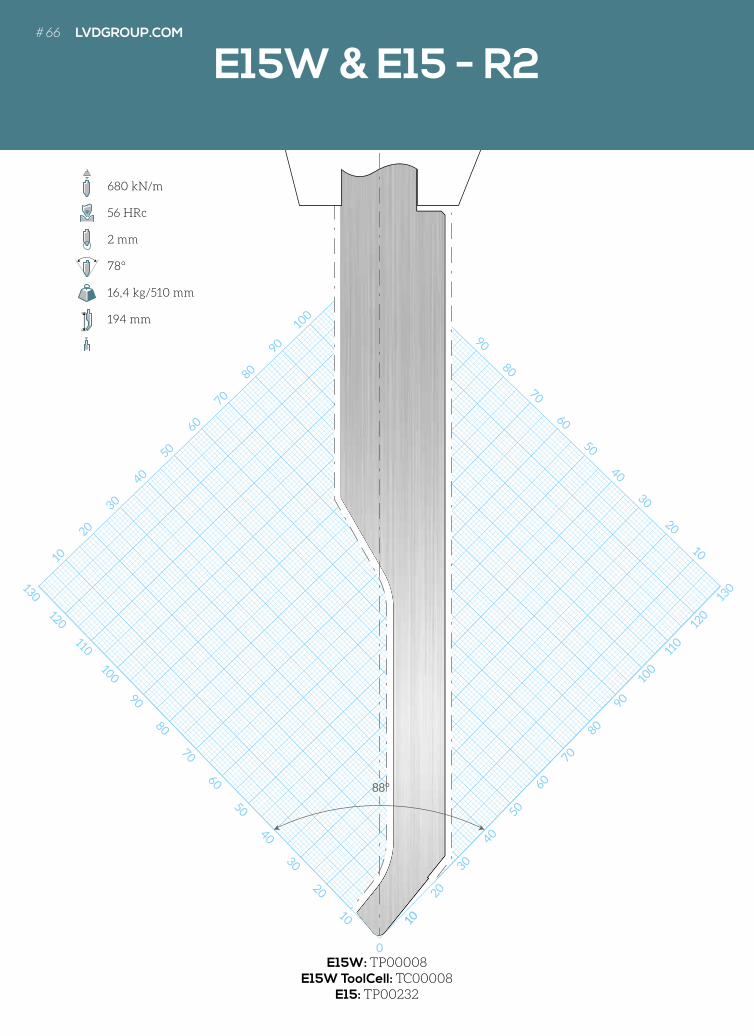
130
120
110
100
90
80
70
60
50
40
30
20
10
130
120
110
10
20
10
20
30
40
50
60
70
80
90
100
110
120
130
0
130
120
110
100
90
80
70
60
50
40
30
20
10
10
20
30
40
50
60
70
80
90
100
110
120
130
130
88°
10
E15W: TP00008E15W ToolCell: TC00008
E15: TP00232
680 kN/m
56 HRc
2 mm
78°
16,4 kg/510 mm
194 mm
E15W & E15 - R2# 66 LVDGROUP.COM
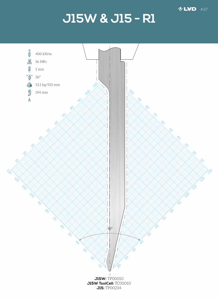
130
120
110
100
90
80
70
60
50
40
30
20
10
130
120
10
20
10
20
30
40
50
60
70
80
90
100
110
120
130
0
120
110
100
90
80
70
60
50
40
30
20
10
10
20
30
40
50
60
70
80
90
100
110
120
130
88°
10
J15W: TP00010J15W ToolCell: TC00010
J15: TP00234
400 kN/m
56 HRc
1 mm
26°
13,1 kg/510 mm
194 mm
E15W & E15 - R2 J15W & J15 - R1# 67
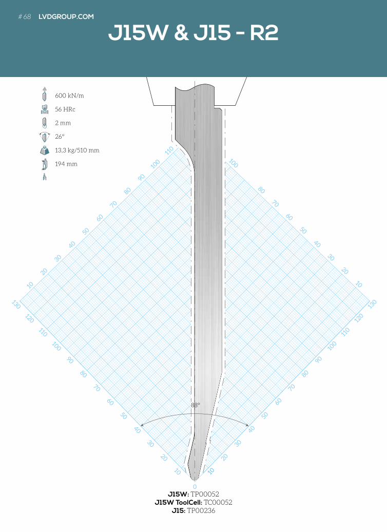
130
120
110
100
90
80
70
60
50
40
30
20
10
130
120
10
20
10
20
30
40
50
60
70
80
90
100
110
120
130
0
130
120
110
100
80
70
60
50
40
30
20
10
10
20
30
40
50
60
70
80
90
100
110
120
130
130
88°
10
J15W: TP00052J15W ToolCell: TC00052
J15: TP00236
600 kN/m
56 HRc
2 mm
26°
13,3 kg/510 mm
194 mm
J15W & J15 - R2# 68 LVDGROUP.COM

130
120
110
100
90
80
70
60
50
40
30
20
10
130
120
10
20
10
20
30
40
50
60
70
80
90
100
110
120
130
0
130
120
110
100
90
80
70
60
50
40
30
20
10
10
20
30
40
50
60
70
80
90
100
110
120
130
130
88°
R15W: TP00014R15W ToolCell: TC00014
R15: TP00238
1200 kN/m
56 HRc
3 mm
26°
16,4 kg/510 mm
194 mm
J15W & J15 - R2 R15W & R15 - R3 # 69
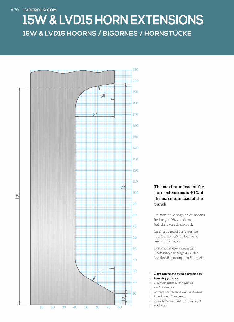
Horn extensions are not available on
hemming punches.
Hoorns zijn niet beschikbaar op
toedrukstempels.
Les bigornes ne sont pas disponibles sur
les poinçons d’écrasement.
Hornstücke sind nicht für Falzstempel
verfügbar.10 20 30 40 50 60 70 80
210
200
190
180
170
160
150
140
130
120
110
100
90
80
70
60
50
40
30
20
10
15W & LVD15 HOORNS / BIGORNES / HORNSTÜCKE
15W & LVD15 HORN EXTENSIONS
The maximum load of the
horn extensions is 40 % of
the maximum load of the
punch.
De max. belasting van de hoorns
bedraagt 40 % van de max.
belasting van de stempel.
La charge maxi des bigornes
représente 40 % de la charge
maxi du poinçon.
Die Maximalbelastung der
Hornstücke beträgt 40 % der
Maximalbelastung des Stempels.
# 70 LVDGROUP.COM
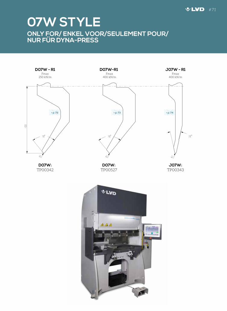
07W STYLEONLY FOR/ ENKEL VOOR/SEULEMENT POUR/ NUR FÜR DYNA-PRESS
Fmax250 kN/m
Fmax400 kN/m
Fmax400 kN/m
D07W - R1 J07W - R1D07W-R1
D07W: TP00342
J07W: TP00343
D07W: TP00527
130
120
110
100
90
80
70
60
50
40
30
20
10
10
20
30
40
50
60
70
80
90
0
40
30
20
10
110
100
90
80
70
60
50
40
30
20
10
10
20
30
40
50
60
70
80
90
100
110
120
130
90
100
110
88°
130
120
110
100
90
80
70
60
50
40
30
20
10
10
20
30
40
50
60
70
80
90
0
40
30
20
10
110
100
90
80
70
60
50
40
30
20
1010
20
30
40
50
60
70
80
90
100
110
120
130
90
100
110
88°
130
120
110
100
90
80
70
60
50
40
30
20
1010
20
30
40
50
60
70
80
90
0
40
30
20
10
110
100
90
80
70
60
50
40
30
20
10
10
20
30
40
50
60
70
80
90
100
110
120
130
90
100
110
88°
> p. 72 > p. 73 > p. 74
# 71
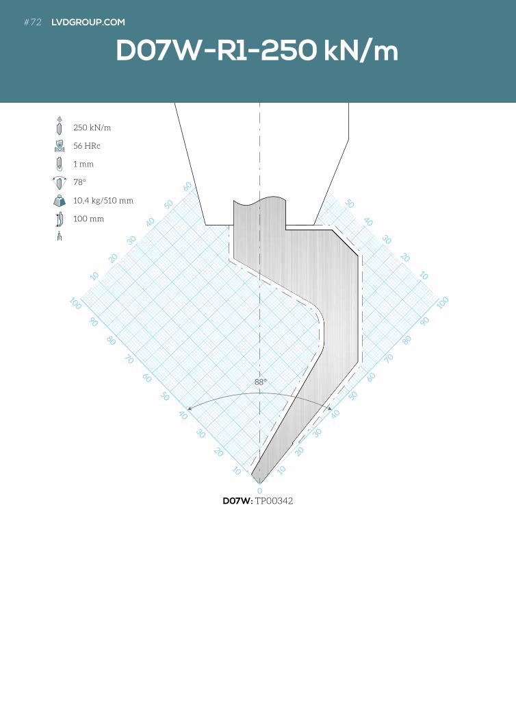
130
120
110
100
90
80
70
60
50
40
30
20
10 10
20
30
40
10
20
30
40
50
0
10
20
30
40
50
6030
20
10
10
20
30
40
50
60
70
80
90
100
110
120
130
50
40
30
20
10
88°
D07W-R1-250 kN/m
D07W: TP00342
250 kN/m
56 HRc
1 mm
78°
10,4 kg/510 mm
100 mm
# 72 LVDGROUP.COM
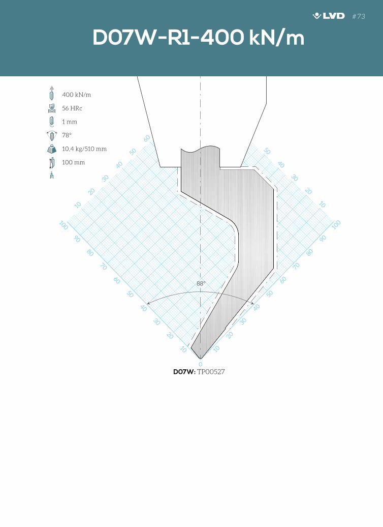
130
120
110
100
90
80
70
60
50
40
30
20
10 10
20
30
40
10
20
30
40
50
0
10
20
30
40
50
6030
20
10
10
20
30
40
50
60
70
80
90
100
110
120
130
50
40
30
20
10
88°
D07W-R1-250 kN/m D07W-R1-400 kN/m
D07W: TP00527
400 kN/m
56 HRc
1 mm
78°
10,4 kg/510 mm
100 mm
# 73
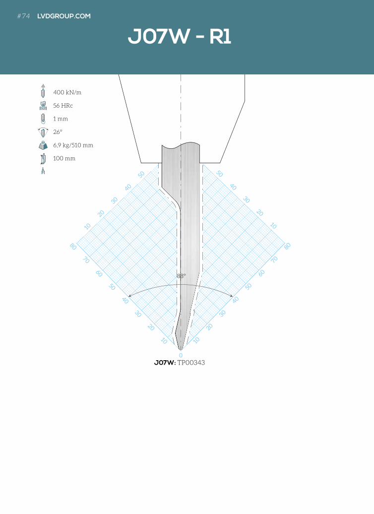
130
120
110
100
90
80
70
60
50
40
30
20
10 10
20
10
20
30
40
50
0
10
20
30
40
50
60
50
40
30
20
10
10
20
30
40
50
60
70
80
90
100
110
120
130
50
40
30
20
10
88°
J07W - R1
J07W: TP00343
400 kN/m
56 HRc
1 mm
26°
6,9 kg/510 mm
100 mm
# 74 LVDGROUP.COM
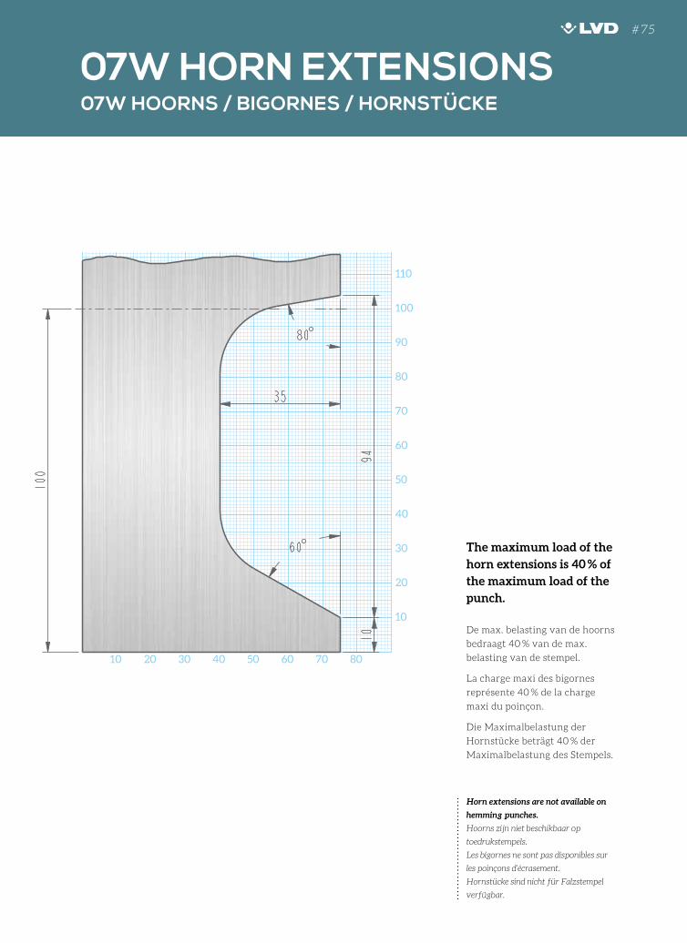
10 20 30 40 50 60 70 80
200
190
180
170
160
150
140
130
120
110
100
90
80
70
60
50
40
30
20
10
07W HOORNS / BIGORNES / HORNSTÜCKE
07W HORN EXTENSIONS
Horn extensions are not available on
hemming punches.
Hoorns zijn niet beschikbaar op
toedrukstempels.
Les bigornes ne sont pas disponibles sur
les poinçons d’écrasement.
Hornstücke sind nicht für Falzstempel
verfügbar.
The maximum load of the
horn extensions is 40 % of
the maximum load of the
punch.
De max. belasting van de hoorns
bedraagt 40 % van de max.
belasting van de stempel.
La charge maxi des bigornes
représente 40 % de la charge
maxi du poinçon.
Die Maximalbelastung der
Hornstücke beträgt 40 % der
Maximalbelastung des Stempels.
# 75
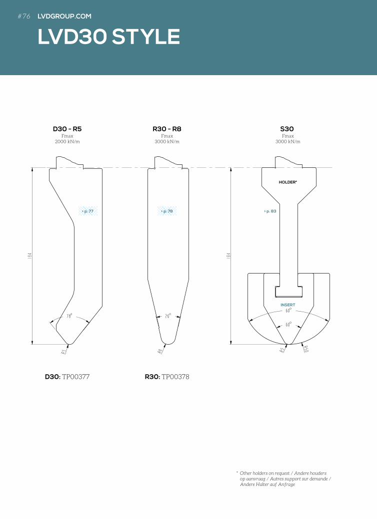
LVD30 STYLE
Fmax2000 kN/m
Fmax3000 kN/m
Fmax3000 kN/m
D30 - R5 R30 - R8 S30
D30: TP00377 R30: TP00378
130
120
110
100
90
80
70
60
50
40
30
20
10
10
20
30
40
50
60
70
80
90
0
40
30
20
10
110
100
90
80
70
60
50
40
30
20
10
10
20
30
40
50
60
70
80
90
100
110
120
130
90
100
110
88°
130
120
110
100
90
80
70
60
50
40
30
20
10
10
20
30
40
50
60
70
80
90
0
40
30
20
10
110
100
90
80
70
60
50
40
30
20
10
10
20
30
40
50
60
70
80
90
100
110
120
130
90
100
110
88°
> p. 77 > p. 78 > p. 83
INSERT
HOLDER*
* Other holders on request / Andere houders op aanvraag / Autres support sur demande / Andere Halter auf Anfrage
LVDGROUP.COM# 76
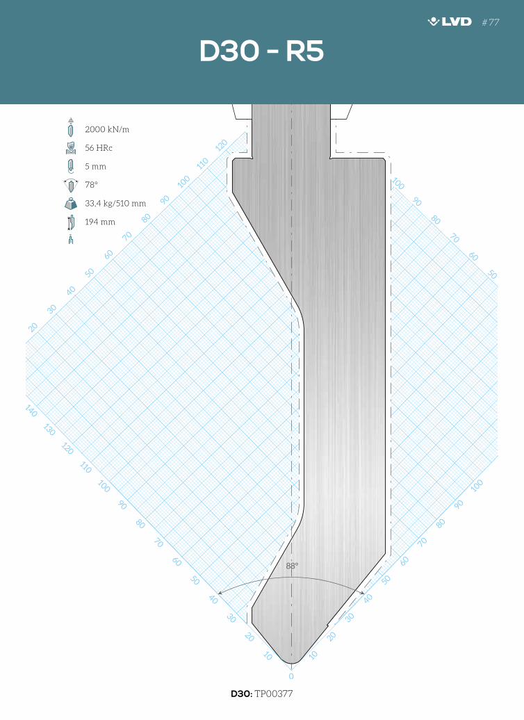
10
20
30
40
50
60
70
80
90
100
110
120
130
140
150
160
170
120
110
100
90
80
70
60
50
40
30
20
10
130
120
110
100
90
10
20
30
40
30
40
50
60
70
80
90
0
50
40
30
20
10
100
90
80
70
60
80
70
60
50
40
30
20
10
20
30
40
50
60
70
80
90
100
110
120
130
140
150
160
130
88°
D30: TP00377
D30 - R5
2000 kN/m
56 HRc
5 mm
78°
33,4 kg/510 mm
194 mm
# 77
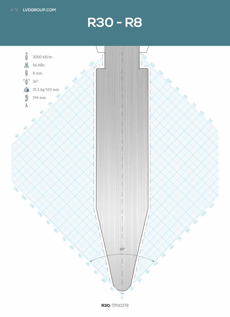
R30: TP00378
10
20
30
40
50
60
70
80
90
100
110
120
130
140
150
160
170
120
110
100
90
80
70
60
50
40
30
20
10
130
120
110
10
20
30
40
50
60
70
80
90
0
50
40
30
20
10
100
110
120
130
90
80
70
60
10
110
100
80
70
60
50
40
30
20
10
20
30
40
50
60
70
80
90
100
110
120
130
140
150
160
120
130
88°
1020
10
0
R30 - R8
3000 kN/m
56 HRc
8 mm
26°
35,5 kg/510 mm
194 mm
# 78 LVDGROUP.COM# 78 LVDGROUP.COM
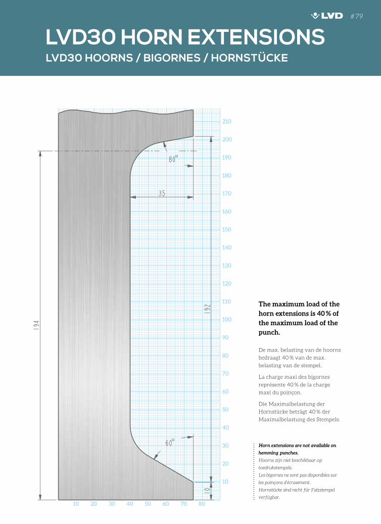
220
10 20 30 40 50 60 70 80
220
210
200
190
180
170
160
150
140
130
120
110
100
90
80
70
60
50
40
30
20
10
LVD30 HOORNS / BIGORNES / HORNSTÜCKE
LVD30 HORN EXTENSIONS
Horn extensions are not available on
hemming punches.
Hoorns zijn niet beschikbaar op
toedrukstempels.
Les bigornes ne sont pas disponibles sur
les poinçons d’écrasement.
Hornstücke sind nicht für Falzstempel
verfügbar.
The maximum load of the
horn extensions is 40 % of
the maximum load of the
punch.
De max. belasting van de hoorns
bedraagt 40 % van de max.
belasting van de stempel.
La charge maxi des bigornes
représente 40 % de la charge
maxi du poinçon.
Die Maximalbelastung der
Hornstücke beträgt 40 % der
Maximalbelastung des Stempels.
# 79
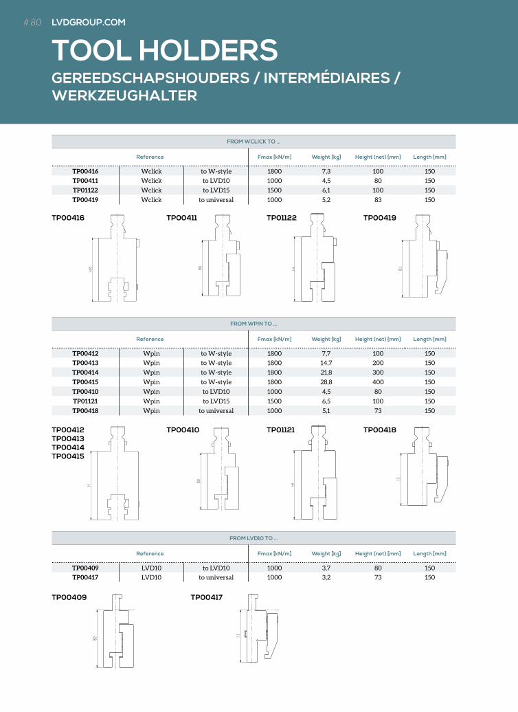
TP00409 TP00417
TP00412TP00413TP00414TP00415
TP00410 TP00418
TP00416 TP00411 TP00419TP01122
TP01121
GEREEDSCHAPSHOUDERS / INTERMÉDIAIRES / WERKZEUGHALTER
TOOL HOLDERS
FROM WCLICK TO …
Reference Fmax [kN/m] Weight [kg] Height (net) [mm] Length [mm]
TP00416 Wclick to W-style 1800 7,3 100 150
TP00411 Wclick to LVD10 1000 4,5 80 150
TP01122 Wclick to LVD15 1500 6,1 100 150
TP00419 Wclick to universal 1000 5,2 83 150
FROM WPIN TO …
Reference Fmax [kN/m] Weight [kg] Height (net) [mm] Length [mm]
TP00412 Wpin to W-style 1800 7,7 100 150
TP00413 Wpin to W-style 1800 14,7 200 150
TP00414 Wpin to W-style 1800 21,8 300 150
TP00415 Wpin to W-style 1800 28,8 400 150
TP00410 Wpin to LVD10 1000 4,5 80 150
TP01121 Wpin to LVD15 1500 6,5 100 150
TP00418 Wpin to universal 1000 5,1 73 150
FROM LVD10 TO …
Reference Fmax [kN/m] Weight [kg] Height (net) [mm] Length [mm]
TP00409 LVD10 to LVD10 1000 3,7 80 150
TP00417 LVD10 to universal 1000 3,2 73 150
# 80 LVDGROUP.COM# 80 LVDGROUP.COM
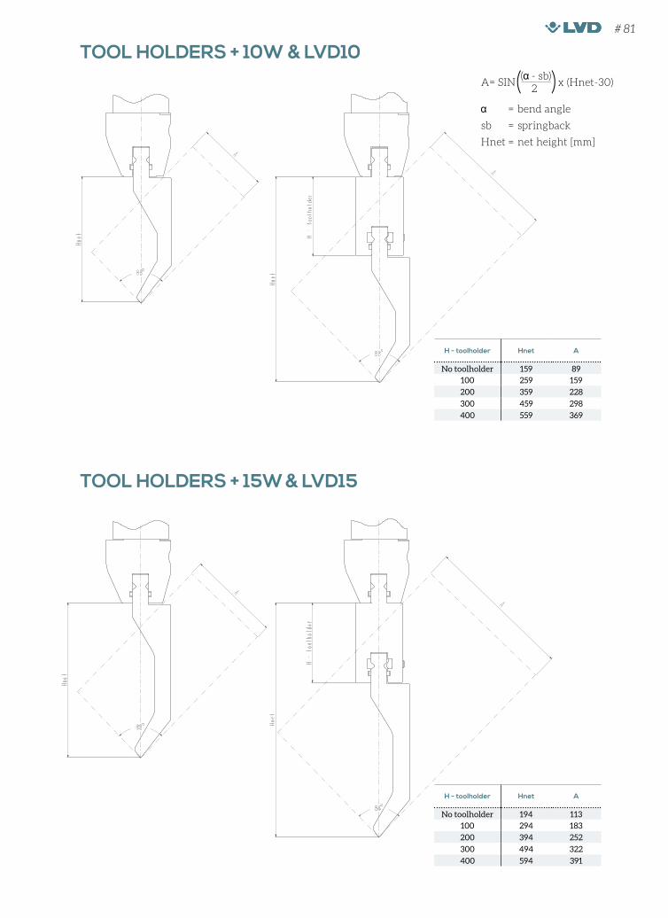
TOOL HOLDERS + 10W & LVD10
TOOL HOLDERS + 15W & LVD15
H - toolholder Hnet A
No toolholder 194 113
100 294 183
200 394 252
300 494 322
400 594 391
H - toolholder Hnet A
No toolholder 159 89
100 259 159
200 359 228
300 459 298
400 559 369
= bend angle
sb = springback
Hnet = net height [mm]
A= SIN x (Hnet-30)( - sb)
2
# 81

LENGTE RADIUSSTEMPELS / LONGUEUR POINÇONS RAYON / LÄNGE RADIUSSTEMPEL
250 MM
510 MM
550 MM SECTIONALISEDGEDEELD/FRACTIONNÉ/SEKTIONIERT
RADIUS PUNCH LENGTHS
510 mm
250 mm
20 mm 20 mm 25 mm 25 mm 30 mm 35 mm 40 mm 40 mm 45 mm 75 mm75 mm
120 mm
# 82 LVDGROUP.COM# 82 LVDGROUP.COM
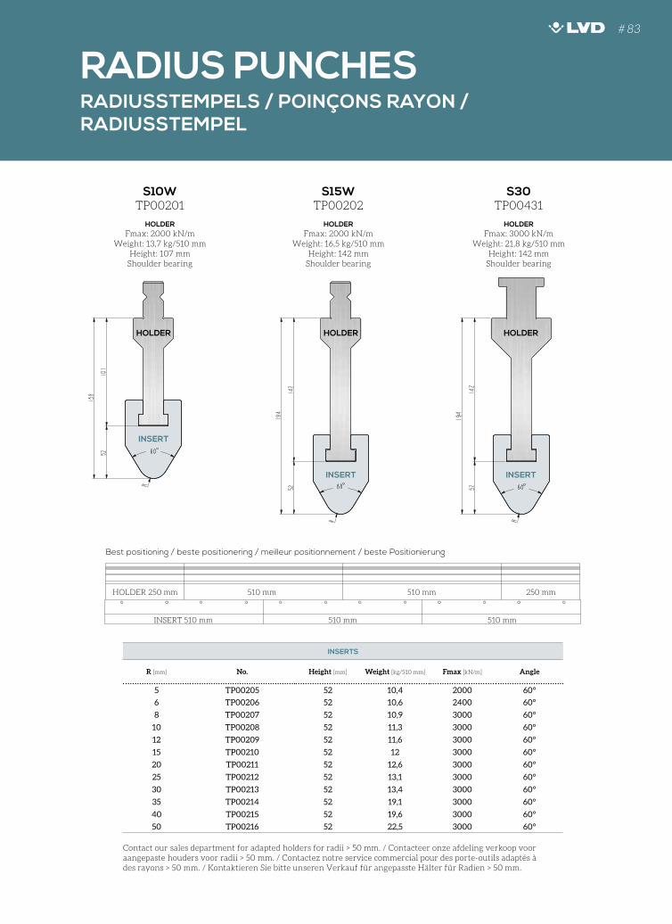
RADIUSSTEMPELS / POINÇONS RAYON / RADIUSSTEMPEL
TP00201
HOLDERFmax: 2000 kN/m
Weight: 13,7 kg/510 mmHeight: 107 mm
Shoulder bearing
INSERT
HOLDER
INSERT
HOLDER
INSERT
HOLDER
TP00202
HOLDERFmax: 2000 kN/m
Weight: 16,5 kg/510 mmHeight: 142 mm
Shoulder bearing
TP00431
HOLDERFmax: 3000 kN/m
Weight: 21,8 kg/510 mmHeight: 142 mm
Shoulder bearing
S10W
Best positioning / beste positionering / meilleur positionnement / beste Positionierung
S15W S30
INSERTS
R [mm] No. Height [mm] Weight [kg/510 mm] Fmax [kN/m] Angle
5 TP00205 52 10,4 2000 60°
6 TP00206 52 10,6 2400 60°
8 TP00207 52 10,9 3000 60°
10 TP00208 52 11,3 3000 60°
12 TP00209 52 11,6 3000 60°
15 TP00210 52 12 3000 60°
20 TP00211 52 12,6 3000 60°
25 TP00212 52 13,1 3000 60°
30 TP00213 52 13,4 3000 60°
35 TP00214 52 19,1 3000 60°
40 TP00215 52 19,6 3000 60°
50 TP00216 52 22,5 3000 60°
RADIUS PUNCHES
Contact our sales department for adapted holders for radii > 50 mm. / Contacteer onze afdeling verkoop voor aangepaste houders voor radii > 50 mm. / Contactez notre service commercial pour des porte-outils adaptés à des rayons > 50 mm. / Kontaktieren Sie bitte unseren Verkauf für angepasste Hälter für Radien > 50 mm.
HOLDER 250 mm 510 mm
INSERT 510 mm 510 mm 510 mm
510 mm 250 mm
# 83
Digitalization inMachine Tool Manufacturing
siemens.com/ sinumerik
Increased efficiency, enhanced flexibility and shorter time tomarket – all this is promised by digitalization. Whether integratedengineering in machine development or networking machinetools in a production landscape:
We support machine builders as well as machine tool users withour solutions! The basis is always our SINUMERIK® CNC with itsopenness and technological bandwidth.
Ad Sie LVD 200x275 1/2018_Opmaak 1 26/01/18 10:13 Pagina 1
HE
MM
ING
AN
D C
US
TO
M T
OO
LS
TOEDRUK- EN MAATWERKGEREEDSCHAPPENOUTILS D’ÉCRASEMENT ET SUR MESUREFALZ- UND MAßGEFERTIGTE WERKZEUGE
HEMMINGAND CUSTOM TOOLS

TOEDRUKGEREEDSCHAPPEN / OUTILS D’ÉCRASEMENT / FALZWERKZEUGE
HEMMING TOOLS
1
3
2
4
BEND SEQUENCE / PLOOIVOLGORDE /SÉQUENCE DE PLIAGE / BIEGEFOLGE
# 86 LVDGROUP.COM
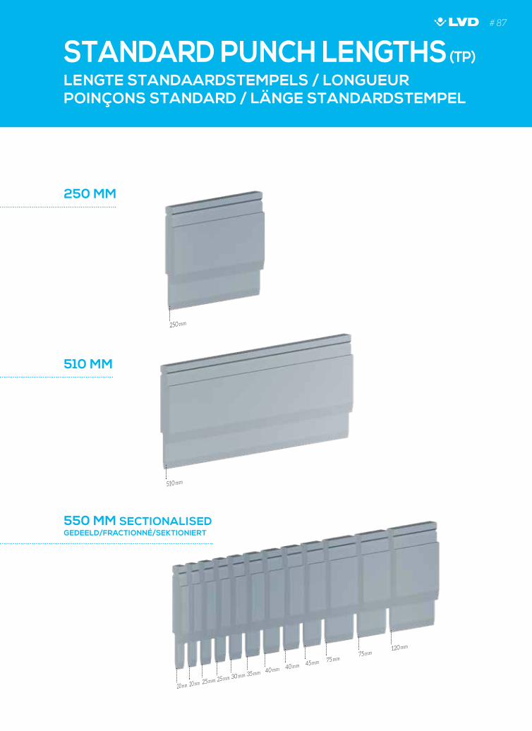
250 MM
550 MM SECTIONALISEDGEDEELD/FRACTIONNÉ/SEKTIONIERT
510 MM
LENGTE STANDAARDSTEMPELS / LONGUEUR POINÇONS STANDARD / LÄNGE STANDARDSTEMPEL
STANDARD PUNCH LENGTHS (TP)
510 mm
250 mm
20 mm 20 mm 25 mm 25 mm 30 mm 35 mm 40 mm 40 mm 45 mm 75 mm75 mm
120 mm
# 87
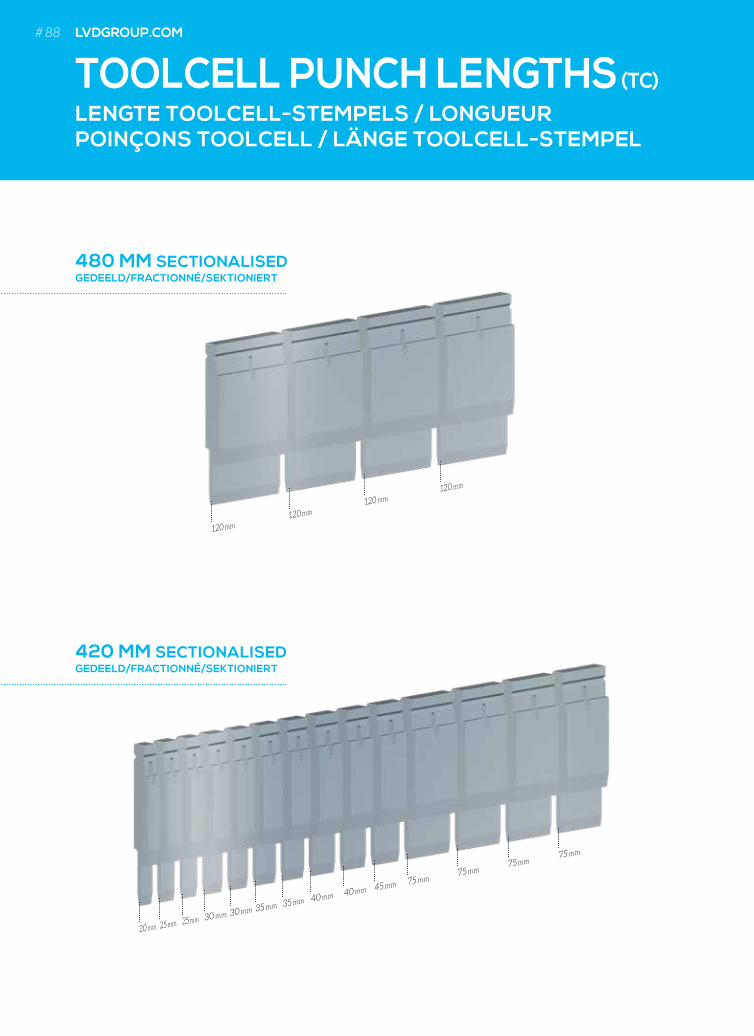
420 MM SECTIONALISEDGEDEELD/FRACTIONNÉ/SEKTIONIERT
480 MM SECTIONALISEDGEDEELD/FRACTIONNÉ/SEKTIONIERT
LENGTE TOOLCELL-STEMPELS / LONGUEUR POINÇONS TOOLCELL / LÄNGE TOOLCELL-STEMPEL
TOOLCELL PUNCH LENGTHS (TC)
120 mm
120 mm120 mm
120 mm
20 mm 25 mm 25 mm 30 mm 30 mm 35 mm 35 mm 40 mm 40 mm 45 mm 75 mm
75 mm
75 mm
75 mm
LVDGROUP.COM# 88 LVDGROUP.COM
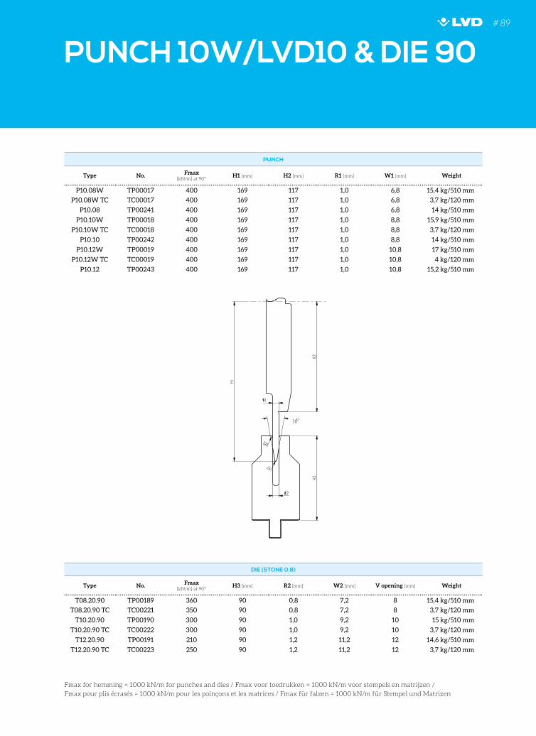
PUNCH 10W/LVD10 & DIE 90
PUNCH
Type No. Fmax [kN/m] at 90°
H1 [mm] H2 [mm] R1 [mm] W1 [mm] Weight
P10.08W TP00017 400 169 117 1,0 6,8 15,4 kg/510 mm
P10.08W TC TC00017 400 169 117 1,0 6,8 3,7 kg/120 mm
P10.08 TP00241 400 169 117 1,0 6,8 14 kg/510 mm
P10.10W TP00018 400 169 117 1,0 8,8 15,9 kg/510 mm
P10.10W TC TC00018 400 169 117 1,0 8,8 3,7 kg/120 mm
P10.10 TP00242 400 169 117 1,0 8,8 14 kg/510 mm
P10.12W TP00019 400 169 117 1,0 10,8 17 kg/510 mm
P10.12W TC TC00019 400 169 117 1,0 10,8 4 kg/120 mm
P10.12 TP00243 400 169 117 1,0 10,8 15,2 kg/510 mm
DIE (STONE 0.8)
Type No. Fmax [kN/m] at 90°
H3 [mm] R2 [mm] W2 [mm] V opening [mm] Weight
T08.20.90 TP00189 360 90 0,8 7,2 8 15,4 kg/510 mm
T08.20.90 TC TC00221 350 90 0,8 7,2 8 3,7 kg/120 mm
T10.20.90 TP00190 300 90 1,0 9,2 10 15 kg/510 mm
T10.20.90 TC TC00222 300 90 1,0 9,2 10 3,7 kg/120 mm
T12.20.90 TP00191 210 90 1,2 11,2 12 14,6 kg/510 mm
T12.20.90 TC TC00223 250 90 1,2 11,2 12 3,7 kg/120 mm
Fmax for hemming = 1000 kN/m for punches and dies / Fmax voor toedrukken = 1000 kN/m voor stempels en matrijzen /
Fmax pour plis écrasés = 1000 kN/m pour les poinçons et les matrices / Fmax für falzen = 1000 kN/m für Stempel und Matrizen
# 89
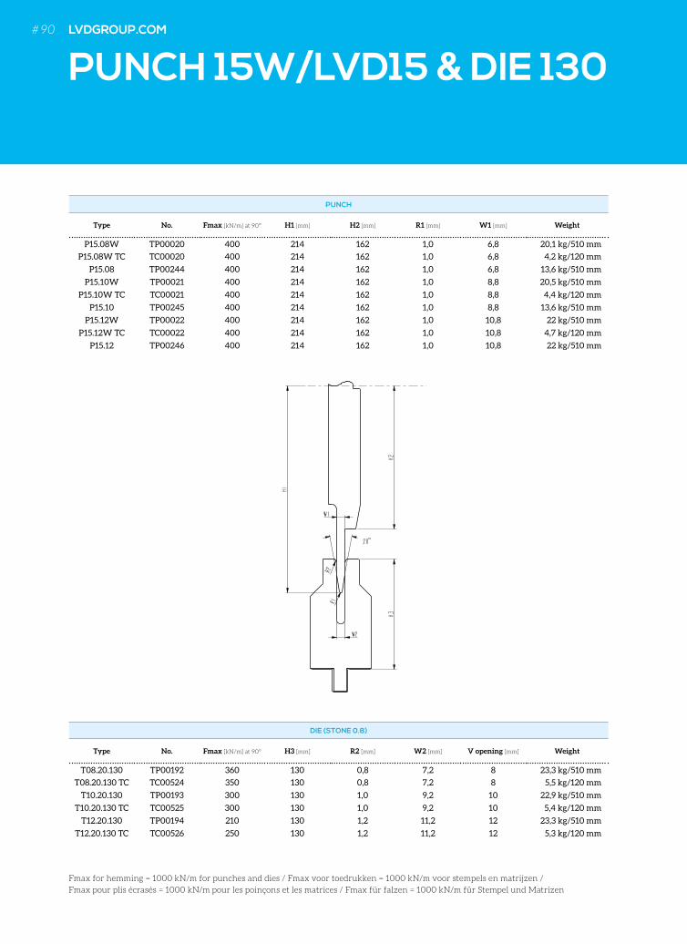
PUNCH
Type No. Fmax [kN/m] at 90° H1 [mm] H2 [mm] R1 [mm] W1 [mm] Weight
P15.08W TP00020 400 214 162 1,0 6,8 20,1 kg/510 mm
P15.08W TC TC00020 400 214 162 1,0 6,8 4,2 kg/120 mm
P15.08 TP00244 400 214 162 1,0 6,8 13,6 kg/510 mm
P15.10W TP00021 400 214 162 1,0 8,8 20,5 kg/510 mm
P15.10W TC TC00021 400 214 162 1,0 8,8 4,4 kg/120 mm
P15.10 TP00245 400 214 162 1,0 8,8 13,6 kg/510 mm
P15.12W TP00022 400 214 162 1,0 10,8 22 kg/510 mm
P15.12W TC TC00022 400 214 162 1,0 10,8 4,7 kg/120 mm
P15.12 TP00246 400 214 162 1,0 10,8 22 kg/510 mm
DIE (STONE 0.8)
Type No. Fmax [kN/m] at 90° H3 [mm] R2 [mm] W2 [mm] V opening [mm] Weight
T08.20.130 TP00192 360 130 0,8 7,2 8 23,3 kg/510 mm
T08.20.130 TC TC00524 350 130 0,8 7,2 8 5,5 kg/120 mm
T10.20.130 TP00193 300 130 1,0 9,2 10 22,9 kg/510 mm
T10.20.130 TC TC00525 300 130 1,0 9,2 10 5,4 kg/120 mm
T12.20.130 TP00194 210 130 1,2 11,2 12 23,3 kg/510 mm
T12.20.130 TC TC00526 250 130 1,2 11,2 12 5,3 kg/120 mm
PUNCH 15W/LVD15 & DIE 130
Fmax for hemming = 1000 kN/m for punches and dies / Fmax voor toedrukken = 1000 kN/m voor stempels en matrijzen /
Fmax pour plis écrasés = 1000 kN/m pour les poinçons et les matrices / Fmax für falzen = 1000 kN/m für Stempel und Matrizen
LVDGROUP.COM# 90 LVDGROUP.COM
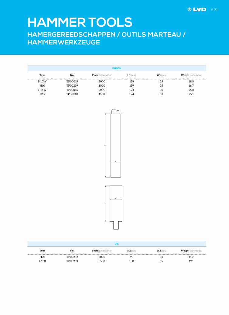
HAMERGEREEDSCHAPPEN / OUTILS MARTEAU / HAMMERWERKZEUGE
HAMMER TOOLS
PUNCH
Type No. Fmax [kN/m] at 90° H1 [mm] W1 [mm] Weight [kg/510 mm]
H10W TP00015 2000 159 25 18,5
H10 TP00239 1000 159 25 16,7
H15W TP00016 2000 194 30 25,8
H15 TP00240 1500 194 30 25,1
DIE
Type No. Fmax [kN/m] at 90° H2 [mm] W2 [mm] Weight [kg/510 mm]
H90 TP00252 3000 90 30 11,7
H130 TP00253 3500 130 35 19,1
# 91
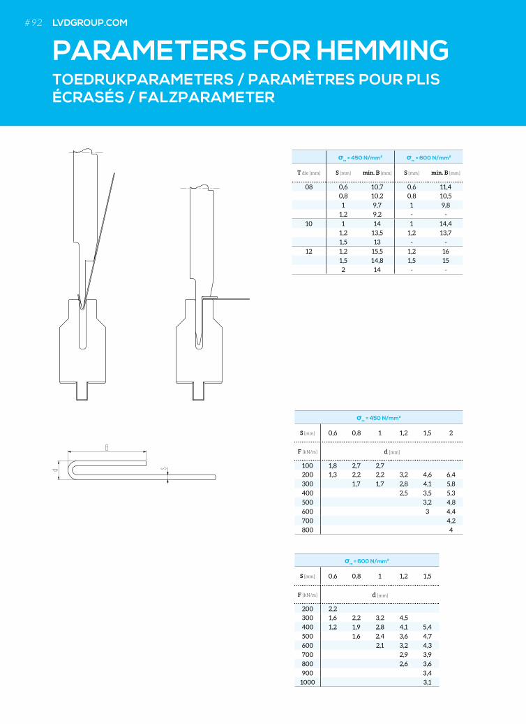
TOEDRUKPARAMETERS / PARAMÈTRES POUR PLIS ÉCRASÉS / FALZPARAMETER
sm = 450 N/mm² sm = 600 N/mm²
T die [mm] S [mm] min. B [mm] S [mm] min. B [mm]
08 0,6 10,7 0,6 11,4
0,8 10,2 0,8 10,5
1 9,7 1 9,8
1,2 9,2 - -
10 1 14 1 14,4
1,2 13,5 1,2 13,7
1,5 13 - -
12 1,2 15,5 1,2 16
1,5 14,8 1,5 15
2 14 - -
PARAMETERS FOR HEMMING
sm = 450 N/mm²
S [mm] 0,6 0,8 1 1,2 1,5 2
F [kN/m] d [mm]
100 1,8 2,7 2,7
200 1,3 2,2 2,2 3,2 4,6 6,4
300 1,7 1,7 2,8 4,1 5,8
400 2,5 3,5 5,3
500 3,2 4,8
600 3 4,4
700 4,2
800 4
sm = 600 N/mm²
S [mm] 0,6 0,8 1 1,2 1,5
F [kN/m] d [mm]
200 2,2
300 1,6 2,2 3,2 4,5
400 1,2 1,9 2,8 4,1 5,4
500 1,6 2,4 3,6 4,7
600 2,1 3,2 4,3
700 2,9 3,9
800 2,6 3,6
900 3,4
1000 3,1
# 92 LVDGROUP.COM
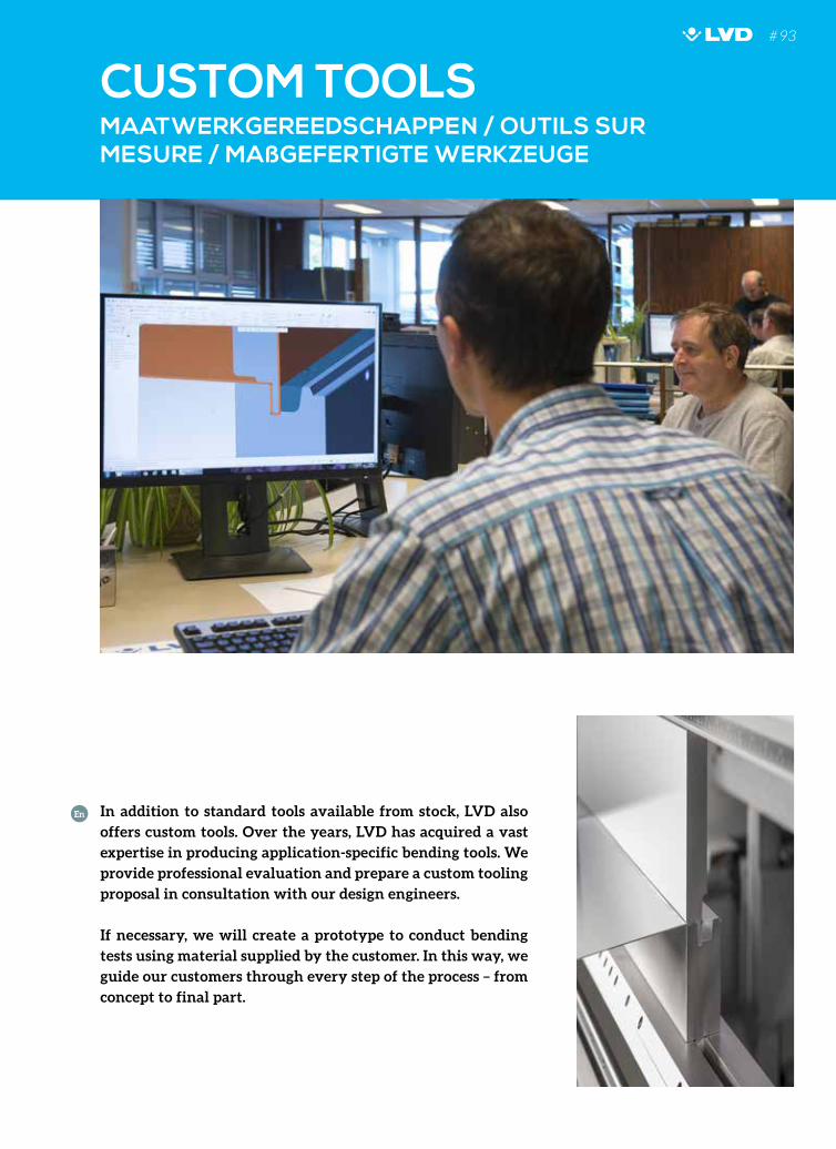
MAATWERKGEREEDSCHAPPEN / OUTILS SUR MESURE / MAßGEFERTIGTE WERKZEUGE
CUSTOM TOOLS
In addition to standard tools available from stock, LVD also
offers custom tools. Over the years, LVD has acquired a vast
expertise in producing application-specific bending tools. We
provide professional evaluation and prepare a custom tooling
proposal in consultation with our design engineers.
If necessary, we will create a prototype to conduct bending
tests using material supplied by the customer. In this way, we
guide our customers through every step of the process – from
concept to final part.
En
# 93
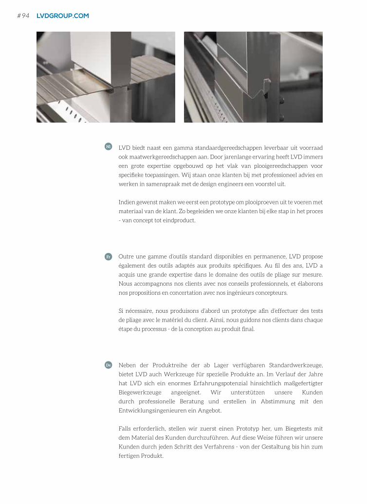
LVD biedt naast een gamma standaardgereedschappen leverbaar uit voorraad
ook maatwerkgereedschappen aan. Door jarenlange ervaring heeft LVD immers
een grote expertise opgebouwd op het vlak van plooigereedschappen voor
specifieke toepassingen. Wij staan onze klanten bij met professioneel advies en
werken in samenspraak met de design engineers een voorstel uit.
Indien gewenst maken we eerst een prototype om plooiproeven uit te voeren met
materiaal van de klant. Zo begeleiden we onze klanten bij elke stap in het proces
- van concept tot eindproduct.
Nl
Outre une gamme d’outils standard disponibles en permanence, LVD propose
également des outils adaptés aux produits spécifiques. Au fil des ans, LVD a
acquis une grande expertise dans le domaine des outils de pliage sur mesure.
Nous accompagnons nos clients avec nos conseils professionnels, et élaborons
nos propositions en concertation avec nos ingénieurs concepteurs.
Si nécessaire, nous produisons d’abord un prototype afin d’effectuer des tests
de pliage avec le matériel du client. Ainsi, nous guidons nos clients dans chaque
étape du processus - de la conception au produit final.
Fr
Neben der Produktreihe der ab Lager verfügbaren Standardwerkzeuge,
bietet LVD auch Werkzeuge für spezielle Produkte an. Im Verlauf der Jahre
hat LVD sich ein enormes Erfahrungspotenzial hinsichtlich maßgefertigter
Biegewerkzeuge angeeignet. Wir unterstützen unsere Kunden
durch professionelle Beratung und erstellen in Abstimmung mit den
Entwicklungsingenieuren ein Angebot.
Falls erforderlich, stellen wir zuerst einen Prototyp her, um Biegetests mit
dem Material des Kunden durchzuführen. Auf diese Weise führen wir unsere
Kunden durch jeden Schritt des Verfahrens - von der Gestaltung bis hin zum
fertigen Produkt.
De
# 94 LVDGROUP.COM
HOW TO ORDER
HO
W T
O O
RD
ER
HOE BESTELLEN COMMENT COMMANDER WIE BESTELLEN
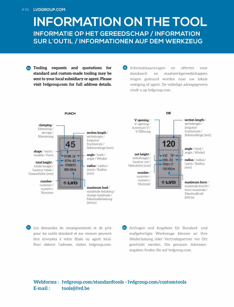
INFORMATION ON THE TOOLINFORMATIE OP HET GEREEDSCHAP / INFORMATION SUR L’OUTIL / INFORMATIONEN AUF DEM WERKZEUG
Les demandes de renseignements et de prix
pour les outils standard et sur mesure peuvent
être envoyées à votre filiale ou agent local.
Pour obtenir l’adresse, visitez lvdgroup.com.
En
Fr
Informatieaanvragen en offertes voor
standaard- en maatwerkgereedschappen
mogen gestuurd worden naar uw lokale
vestiging of agent. De volledige adresgegevens
vindt u op lvdgroup.com.
Anfragen und Angebote für Standard- und
maßgefertigte Werkzeuge können an Ihre
Niederlassung oder Vertriebspartner vor Ort
geschickt werden. Die genauen Adressen-
angaben finden Sie auf lvdgroup.com.
Nl
De
Tooling requests and quotations for
standard and custom-made tooling may be
sent to your local subsidiary or agent. Please
visit lvdgroup.com for full address details.
section length / sectielengte / longueur fractionnée / Sektionslänge [mm]
PUNCH
maximum load / maximale belasting / charge maximale /Maximalbelastung [kN/m]
angle / hoek / angle / Winkel
radius / radius /rayon / Radius [mm]
shape / vorm / modèle / Form
total height / totale hoogte /
hauteur totale / Gesamthöhe [mm]
number / nummer / numéro / Nummer
clamping / klemming /
serrage / Klemmung
DIE
section length / sectielengte / longueur fractionnée / Sektionslänge [mm]
maximum force / maximale kracht / force maximale /Maximalkraft [kN/m]
angle / hoek / angle / Winkel
radius / radius /rayon / Radius [mm]
net height / nettohoogte / hauteur net /
Nettohöhe [mm]
number / nummer / numéro / Nummer
V opening / V-opening /
ouverture V / V-Öffnung
Webforms : lvdgroup.com/standardtools - lvdgroup.com/customtoolsE-mail : [email protected]
# 96 LVDGROUP.COM
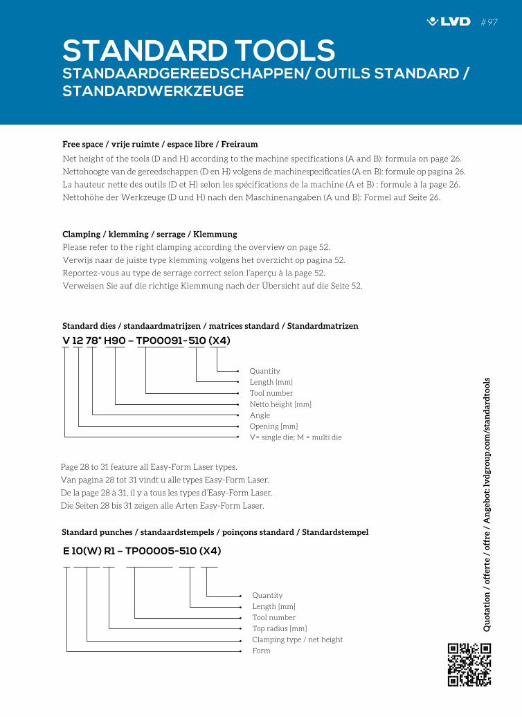
Page 28 to 31 feature all Easy-Form Laser types.
Van pagina 28 tot 31 vindt u alle types Easy-Form Laser.
De la page 28 à 31, il y a tous les types d’Easy-Form Laser.
Die Seiten 28 bis 31 zeigen alle Arten Easy-Form Laser.
Free space / vrije ruimte / espace libre / Freiraum
Net height of the tools (D and H) according to the machine specifications (A and B): formula on page 26.
Nettohoogte van de gereedschappen (D en H) volgens de machinespecificaties (A en B): formule op pagina 26.
La hauteur nette des outils (D et H) selon les spécifications de la machine (A et B) : formule à la page 26.
Nettohöhe der Werkzeuge (D und H) nach den Maschinenangaben (A und B): Formel auf Seite 26.
Clamping / klemming / serrage / Klemmung
Please refer to the right clamping according the overview on page 52.
Verwijs naar de juiste type klemming volgens het overzicht op pagina 52.
Reportez-vous au type de serrage correct selon l’aperçu à la page 52.
Verweisen Sie auf die richtige Klemmung nach der Übersicht auf die Seite 52.
Standard punches / standaardstempels / poinçons standard / Standardstempel
V 12 78° H90 – TP00091-510 (X4)
Quantity
Length [mm]
Tool number
Netto height [mm]
Angle
Opening [mm]
V= single die; M = multi die
E 10(W) R1 – TP00005-510 (X4)
Quantity
Length [mm]
Tool number
Top radius [mm]
Clamping type / net height
Form
STANDARD TOOLSSTANDAARDGEREEDSCHAPPEN/ OUTILS STANDARD / STANDARDWERKZEUGE
Standard dies / standaardmatrijzen / matrices standard / Standardmatrizen
# 97
Qu
otat
ion
/ o
ffer
te /
off
re /
An
geb
ot: l
vd
grou
p.c
om/s
tan
dar
dto
ols
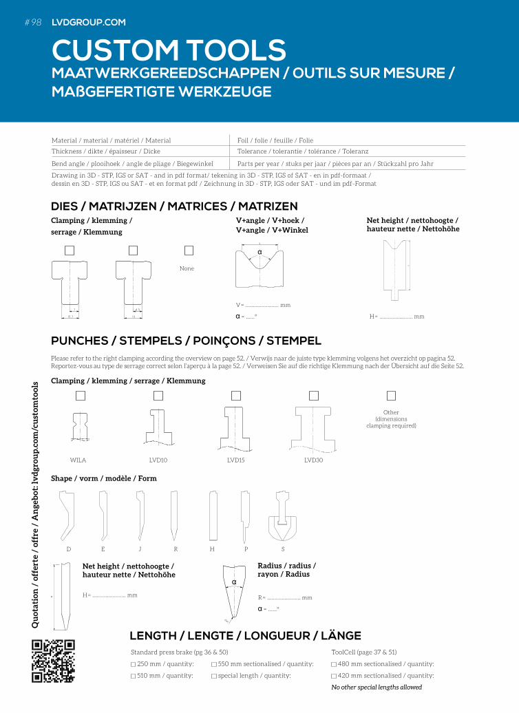
DIES / MATRIJZEN / MATRICES / MATRIZEN
PUNCHES / STEMPELS / POINÇONS / STEMPEL
Clamping / klemming /
serrage / Klemmung
Clamping / klemming / serrage / Klemmung
Shape / vorm / modèle / Form
V = ....................... mm
= ……° H = ....................... mm
Net height / nettohoogte / hauteur nette / Nettohöhe
H = ....................... mm
Standard press brake (pg 36 & 50) ToolCell (page 37 & 51)
250 mm / quantity: 550 mm sectionalised / quantity: 480 mm sectionalised / quantity:
510 mm / quantity: special length / quantity: 420 mm sectionalised / quantity:
No other special lengths allowed
LENGTH / LENGTE / LONGUEUR / LÄNGE
None
WILA
D E J R H P S
LVD10 LVD15 LVD30
Other (dimensions
clamping required)
Radius / radius / rayon / Radius
R = ....................... mm
= ……°
Please refer to the right clamping according the overview on page 52. / Verwijs naar de juiste type klemming volgens het overzicht op pagina 52.Reportez-vous au type de serrage correct selon l’aperçu à la page 52. / Verweisen Sie auf die richtige Klemmung nach der Übersicht auf die Seite 52.
Material / material / matériel / Material Foil / folie / feuille / Folie
Thickness / dikte / épaisseur / Dicke Tolerance / tolerantie / tolérance / Toleranz
Bend angle / plooihoek / angle de pliage / Biegewinkel Parts per year / stuks per jaar / pièces par an / Stückzahl pro Jahr
Drawing in 3D - STP, IGS or SAT - and in pdf format/ tekening in 3D - STP, IGS of SAT - en in pdf-formaat / dessin en 3D - STP, IGS ou SAT - et en format pdf / Zeichnung in 3D - STP, IGS oder SAT - und im pdf-Format
V+angle / V+hoek / V+angle / V+Winkel
Net height / nettohoogte / hauteur nette / Nettohöhe
CUSTOM TOOLSMAATWERKGEREEDSCHAPPEN / OUTILS SUR MESURE / MAßGEFERTIGTE WERKZEUGE
H
Qu
otat
ion
/ o
ffer
te /
off
re /
An
geb
ot: l
vd
grou
p.c
om/c
ust
omto
ols
# 98 LVDGROUP.COM
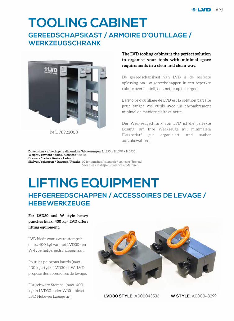
LIFTING EQUIPMENT
TOOLING CABINET
For LVD30 and W style heavy
punches (max. 400 kg), LVD offers
lifting equipment.
LVD biedt voor zware stempels
(max. 400 kg) van het LVD30- en
W-type hefgereedschappen aan.
Pour les poinçons lourds (max.
400 kg) styles LVD30 et W, LVD
propose des accessoires de levage.
Für schwere Stempel (max. 400
kg) in LVD30- oder W-Stil bietet
LVD Hebewerkzeuge an.
The LVD tooling cabinet is the perfect solution
to organise your tools with minimal space
requirements in a clear and clean way.
De gereedschapskast van LVD is de perfecte
oplossing om uw gereedschappen in een beperkte
ruimte overzichtelijk en netjes op te bergen.
L’armoire d’outillage de LVD est la solution parfaite
pour ranger vos outils avec un encombrement
minimal de manière claire et nette.
Der Werkzeugschrank von LVD ist die perfekte
Lösung, um Ihre Werkzeuge mit minimalem
Platzbedarf gut organisiert und sauber
aufzubewahren.
W STYLE: A000043399LVD30 STYLE: A000043536
HEFGEREEDSCHAPPEN / ACCESSOIRES DE LEVAGE / HEBEWERKZEUGE
GEREEDSCHAPSKAST / ARMOIRE D’OUTILLAGE / WERKZEUGSCHRANK
Dimensions / afmetingen / dimensions/Abmessungen: L 1350 x B 1070 x H 1450Weight / gewicht / poids / Gewicht: 468 kgDrawers / lades / tiroirs / Laden: 5Shelves / schappen / étagères / Regale: 10 for punches / stempels / poinçons/Stempel 5 for dies / matrijzen / matrices / Matrizen
Ref.: 78923008
Standard press brake (pg 36 & 50) ToolCell (page 37 & 51)
250 mm / quantity: 550 mm sectionalised / quantity: 480 mm sectionalised / quantity:
510 mm / quantity: special length / quantity: 420 mm sectionalised / quantity:
No other special lengths allowed
LENGTH / LENGTE / LONGUEUR / LÄNGE
# 99
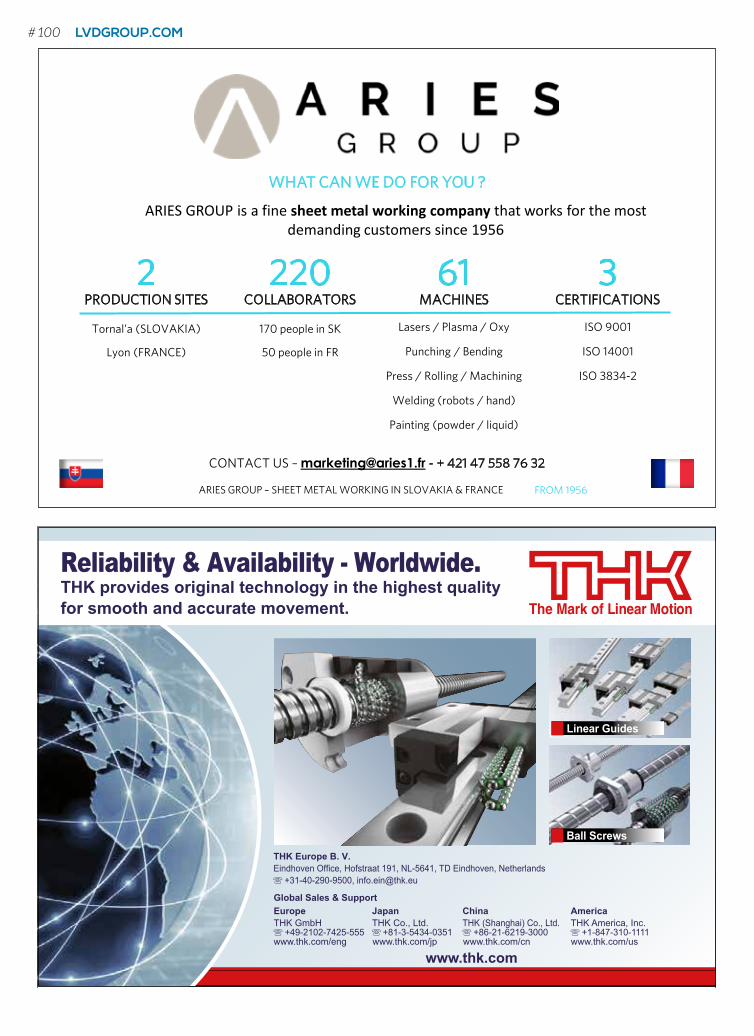
www.thk.com
Reliability & Availability - Worldwide.THK provides original technology in the highest qualityfor smooth and accurate movement.
Linear Guides
Ball Screws THK Europe B. V.Eindhoven Office, Hofstraat 191, NL-5641, TD Eindhoven, Netherlands z +31-40-290-9500, [email protected]
Global Sales & SupportEurope Japan China AmericaTHK GmbH THK Co., Ltd. THK (Shanghai) Co., Ltd. THK America, Inc.z +49-2102-7425-555 z +81-3-5434-0351 z +86-21-6219-3000 z +1-847-310-1111www.thk.com/eng www.thk.com/jp www.thk.com/cn www.thk.com/us
WHAT CAN WE DO FOR YOU ?
ARIES GROUP – SHEET METAL WORKING IN SLOVAKIA & FRANCE FROM 1956
CONTACT US – [email protected] - + 421 47 558 76 32
ARIES GROUP is a fine sheet metal working company that works for the most demanding customers since 1956
2 PRODUCTION SITES
220 COLLABORATORS
61 MACHINES
3 CERTIFICATIONS
Lyon (FRANCE)
Tornal’a (SLOVAKIA) 170 people in SK
50 people in FR
Lasers / Plasma / Oxy
Punching / Bending
Press / Rolling / Machining
Welding (robots / hand)
Painting (powder / liquid)
ISO 14001
ISO 9001
ISO 3834-2
# 100 LVDGROUP.COM
SIGMAWeiterverarbeitungs GmbH & Co. KGIndustriestraße 1D–66763 Dillingen/Saar
contact person:Christian WeilandTel.: +49(0)6831 / 7609–49Fax.: +49(0)6831 / 7609–60E-Mail: [email protected]
web: www.swwp.de
www.connected-hydraulics.com
Bosch Rexroth is your global partner for powerful, proven hydraulic drive solutions for every application, continually setting new benchmarks for performance, functionality and lifetime. We help our customers to master force and torque. Our complete portfolio cost-effectively serves standard applications as well as complex motion tasks with the most demanding requirements.We exceed your expectations, applying our unique expertise to go beyond limits. Our connected hydraulics solutions fit seamlessly into modern control architectures: from small to large, from series to project business, all backed by worldwide service.We move everything – mastering force and torque
REXR_ConHyd_AD_A5_A.indd 1 22.03.2017 13:59:29
# 101
# 102 LVDGROUP.COM
Rittal nv/saIndustrieterrein E17/3206 - Stokkelaar 8 - 9160 LokerenT 09 353 91 11 - [email protected] - www.rittal.be
Rittal Automation SystemsWe automate the panel building.

LASER
PUNCH
INTEGRATE
BEND
For full address details of your local subsidiary or agent, please visit our website. / De volledige adresgegevens van uw lokale vestiging of agent, vindt u op onze website. / Pour obtenir l’adresse de votre filiale ou agent local, veuillez visiter notre site web. / Die genauen Adressangaben einer Niederlassung oder eines Vertriebspartners vor Ort, finden Sie auf unserer Webseite.
LVD Company nv
Nijverheidslaan 2, B-8560 GULLEGEM, BELGIUM
Tel. +32 56 43 05 11 - [email protected]
LVDGROUP.COM