
Dendritic MRI contrast agents - Technische Universiteit Eindhoven
TECHNISCHE UNIVERSITEIT EINDHOVEN
Department of Mathematics and Computer Science
MASTER THESIS
Design Environment for
Adaptive Web Application Development
by
ing. R. Kochen
Supervisors: prof. dr. ir. G.J.P.M. Houben
ir. K.A.M. van der Sluijs
Eindhoven, June 06
Abstract
This master thesis, along with the Hera Studio application, is the result of my graduation project at the Hera research group [1] of the Technische Universiteit Eindhoven. The Hera research group focuses on research in the area of Web Engineering and Web-based Information Systems (WIS).
Because modern WISs have complex structures and are difficult to implement, various design approaches are developed. Hera is the name of a model-driven methodology, developed by the Hera research group, for designing WISs, using the separation-of-concerns principle which distinguishes the content data from the navigational structure and from the presentational issues, resulting in three layers: semantic layer, application layer and presentation layer. The specification in each layer is captured by means of one or more models.
The Hera methodology [2] is part of the Hera framework which also contains an engine, called the Hera Presentation Generator (HPG) [3]. This engine interprets the Hera models (the WIS specification) and implements a WIS. Currently HPG needs the models to be specified in the RDFS/XML [4] format. Because RDFS/XML is a verbose format and creating it by hand is tedious and error prone, editors were developed which facilitate the construction of the models by providing ways to visually construct them. However, the current model editors have several shortcomings.
The goal of the project was the development of an application, called Hera Studio, for designing WISs with improved model editors. This thesis reports the way how Hera Studio is designed and implemented. Hera Studio features a model editor, capable of constructing two types of models and exporting them to RDFS/XML. These model types are also defined in this thesis by means of meta-models.
2

Preface
This master thesis describes the result of my graduation period at the Hera research group (part of the Information Systems science group) and finishes my computer science study at the Technische Universiteit Eindhoven.
I want to thank Kees van der Sluijs, Geert-Jan Houben, Ad Aerts and Peter Barna for their advice and positive cooperation. Also I want to thank the other people in room HG7.45 for a pleasant working atmosphere.
René Kochen
3
Table of contents
ABSTRACT .................................................................................................................................................. 2 PREFACE ..................................................................................................................................................... 3 TABLE OF CONTENTS ............................................................................................................................. 4 ABBREVIATIONS....................................................................................................................................... 5 CHAPTER 1: INTRODUCTION ............................................................................................................... 6
1.1 AWIS ................................................................................................................................................... 6 1.2 HERA FRAMEWORK............................................................................................................................... 7 1.3 HERA METHODOLOGY........................................................................................................................... 7 1.4 ASSIGNMENT ........................................................................................................................................ 9
CHAPTER 2: HERA MODELS................................................................................................................ 10 2.1 CONCEPTUAL META-MODEL ............................................................................................................... 11 2.2 APPLICATION META-MODEL................................................................................................................ 17
CHAPTER 3: HERA STUDIO.................................................................................................................. 24 3.1 REQUIREMENTS .................................................................................................................................. 24 3.2 USING HERA STUDIO .......................................................................................................................... 25
CHAPTER 4: PROGRAM DESIGN........................................................................................................ 32 4.1 DATA BINDING.................................................................................................................................... 32 4.2 PROGRAM STRUCTURE........................................................................................................................ 34
CHAPTER 5: CONCLUSION AND RECOMMENDATIONS ............................................................. 39 REFERENCES ........................................................................................................................................... 41 APPENDIX: RDF....................................................................................................................................... 43
5.1 RDF.................................................................................................................................................... 43 5.2 RDFS ................................................................................................................................................. 44 5.3 HPG AND RDF(S) .............................................................................................................................. 44
APPENDIX: DATA BINDING ................................................................................................................. 50 APPENDIX: IMDB .................................................................................................................................... 54
4
Abbreviations
AWIS : Adaptive Web Information System
WIS : Web Information System
AM : Application Model
CM : Conceptual Model
TM : Transient Model
PM : Presentation Model
RDF : Resource Description Framework
RDFS : Resource Description Framework Schema
HPG : Hera Presentation Generator
AWT : Abstract Window Toolkit
UML : Unified Modeling Language
DOM : Document Object Model
SAX : Simple API for XML
StAX : Streaming API for XML
5
Chapter 1: Introduction
This chapter introduces the notion of an Adaptive Web Information System (AWIS), the Hera framework, and the Hera methodology. The last subchapter describes the assignment. Parts of this chapter are based on [5].
1.1 AWIS
In the early days, a Web Information System (WIS) consisted of a static collection of pages and links interconnecting them, creating a hypermedia presentation. The information was determined beforehand and the presentation was static. When time passed, more and more data sources were connected to the Web and more information became available for the WIS. The typical WIS became a data-intensive Web application, i.e. using data from (multiple) data sources. Page content became dynamic, meaning that only relevant information from the data-sources is extracted and information shown in the presentation is adapted. This leads to the notion of an AWIS. However, the traditional approach of handcrafting the hypermedia presentation does not work in this scheme, because the context sensitivity of presentations forces page content to be determined at runtime. Modern AWIS share the following characteristics:
- Personalization The notion of personalization means that a hypermedia presentation is adapted to suit the end-users context, as opposed to the one-size-fits-all approach. The user context is captured in a user/platform profile and a user model. A user/platform profile describes static user requirements, i.e. constant during the entire presentation (e.g. platform capabilities), while the user model describes dynamic user requirements (e.g. browsing history). When the presentation uses the user/platform profile to personalize the presentation, we say that the presentation is made adaptable. When the presentation uses the user model to personalize the presentation, we say that the presentation is made adaptive.
- Dynamic generation Because a modern AWIS is often interactive, e.g. a shopping basket at an online store, and the presented information is often personalized, the presentation generation process is often dynamic. Page content is determined and generated at runtime.
- Integration Information can be gathered from different heterogeneous sources, i.e. sources using different data models and data definitions. This requires the AWIS to specify which sources to select and how to interpret its data.
- Interoperability A modern AWIS is not only a self-standing application. It often needs to interact with other systems, either to gather data from them or to serve as data provider itself.
6
1.2 Hera framework
The main goal of the Hera framework is to provide support for AWIS design and implementation. The framework consists of:
- A model-driven methodology for AWIS design purposes, described in the next section.
- A software suite consisting of:
o Editors Programs facilitating the construction of an AWIS design. These programs, among others, provide ways to visually construct the models of the Hera methodology. Currently there are two Visio [6] implementations to create two types of models and export them to RDFS/XML. Chapter 3 discusses the new application called Hera Studio which also features a visual model editor.
o Engines Programs that “execute” the model specifications created during the design phase, i.e. they interpret the models and implement the data transformation pipeline. The Hera Presentation Generator (HPG) 2.x application [3] is currently the most complete solution, supporting most of the models of the Hera methodology.
1.3 Hera methodology
A classic WIS was relatively simple and static. However, modern WIS, featuring automated personalization, integration, etc, have a complex structure and are not easily designed and implemented. This necessitates the development of new design approaches which abstract from fixed implementations by providing a generic methodology to create specific WISs. The Hera methodology is such an approach. Examples of other approaches are the Relationship Management Methodology (RMM) [7] and the Object-Oriented Hypermedia Design Methodology (OOHDM) [8].
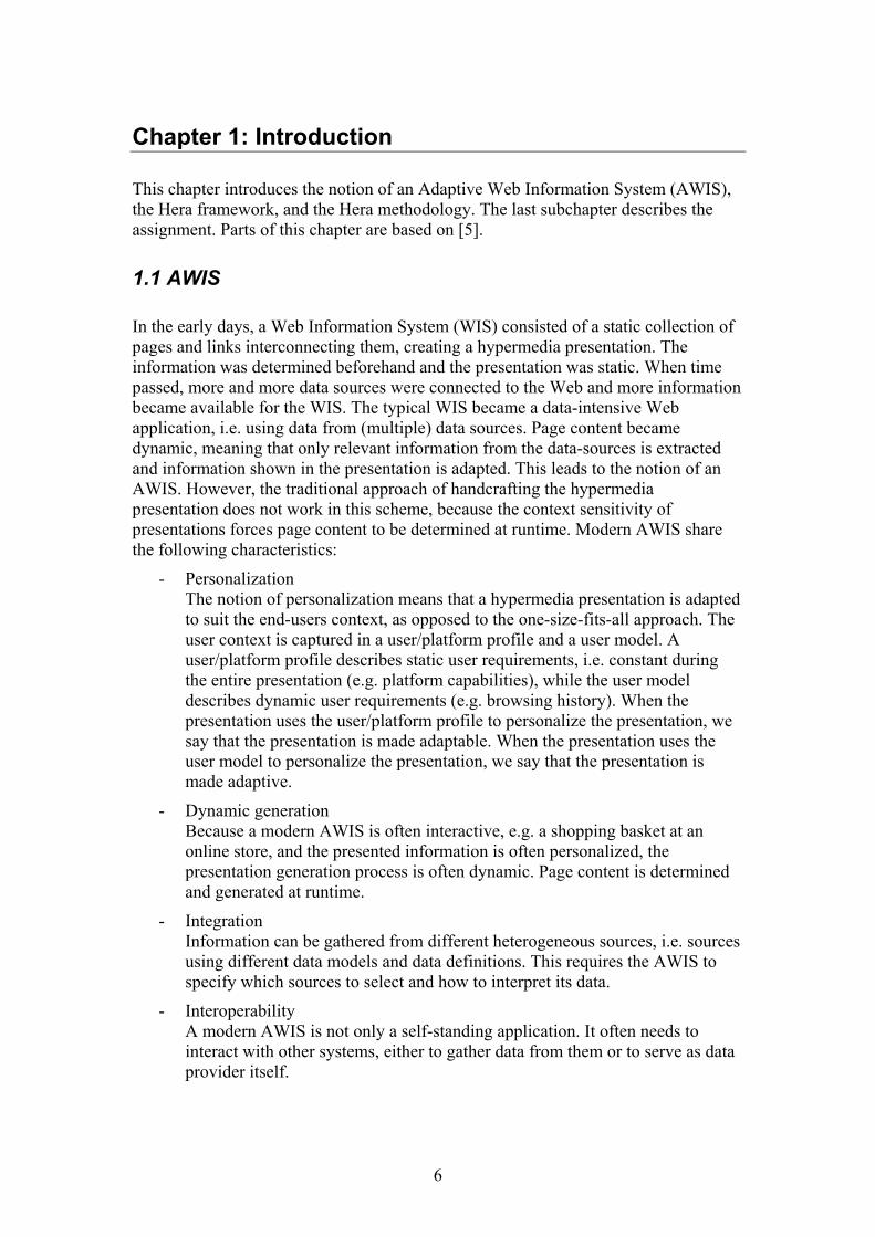
Using the separation-of-concerns principle, the Hera methodology distinguishes the content data from the navigational structure and from the presentational issues, resulting in three layers: semantic layer, application layer and presentation layer. The design in each layer is captured in terms of one or more models. During the presentation generation process, data pass through these layers, each layer transforming the data, resulting in a two-way process: the data retrieval/integration process (the transformations in the semantic layer) and a presentation generation process (the transformations in the application layer and presentation layer). Transformation specifications and intermediate transformation results are both expressed as models and model instances respectively.
- Semantic layer This layer defines the content that is managed in the AWIS in terms of a conceptual model (CM) which defines a logical global view of the data. At runtime, a conceptual model instance (CMI) (an instance of the CM with
7
instance data, e.g. the name of a product) is used as the data source of the AWIS and passed on to the application layer.
- Application layer Data from the conceptual model must be grouped together and linked to each other to create a hypermedia presentation. The application layer defines the abstract hypermedia (navigation) view on the data of the CM in terms of an application model (AM), which represents the structure of the hypermedia presentation. This layer also includes the definition of the adaptation in the hypermedia generation, e.g. based on a user model and a user/platform profile. At runtime, the transformation process in this layer starts from the data that constitutes the result of the transformations in the semantic layer, represented by the CMI. The CMI is transformed, using the AM, into an application model instance (AMI). The AMI is an instance of the AM and describes a concrete navigational view of the presentation with actual data from the CMI. The AMI is passed to the presentation layer.
- Presentation layer The way a presentation looks on a platform is determined by the presentation layer. Parts of the AM are grouped and associated with presentation properties, e.g. position of a presentation element. Presentation layer design is captured in a presentation model (PM), describing a presentation view over the AM. At runtime the AMI of the application layer, using the presentation model, is transformed into a presentation model instance (PMI). The PMI is an instance of the PM and describes the actual presentation: the data, navigational structure and looks. Subsequently this PMI is converted into a platform specific format, e.g. HyperText Markup Language (HTML) or Wireless Markup Language (WML), and returned to the end-user.
Figure 1: Hera methodology
8
Figure 1 shows a schematic overview of the Hera methodology. Note that the above description is simplified. For a more throughout covering of the Hera methodology, the reader is encouraged to read [2]. Also note that the models, as well as the specification of the models, are subject to change. See [1] for references to up to date material.
1.4 Assignment
As stated earlier in this chapter, the Hera framework consists of a model-driven design approach to design AWISs. This design results in several models that constitute the specification of the AWIS. In addition, the framework contains software facilitating the model design process and software that interpret the models and implement the AWIS (based on those models).
The current HPG application, which interprets the models, requires them to be specified in RDFS/XML. Because RDFS/XML is a verbose format and creating it by hand is tedious and error-prone, editors were developed which facilitate the construction of the models by providing ways to visually construct them. The editor then converts the graphic model to RDFS/XML. Two Visio implementations were developed, one for the conceptual model and one for the application model. However, these editors had several shortcomings, which are discussed in chapter 3.
The goal of the project was the development of an application, called Hera Studio, for designing WISs with improved model editors for the conceptual model and the application model. Chapter 3 discusses the Hera Studio application and its requirements.
9
Chapter 2: Hera models
As described in the previous chapter, the Hera methodology contains several models, each model describing a different aspect of a WIS. This chapter provides definitions of the conceptual model and the application model.
HPG requires the models to be specified in RDFS/XML. Because RDFS/XML is a verbose format, the models are modeled and defined using custom graphical elements, called items. This graphical representation differs from the RDFS representation. Hera Studio (discussed in the next chapter) translates the custom graphical representation to the RDFS/XML serialized representation, required by HPG.
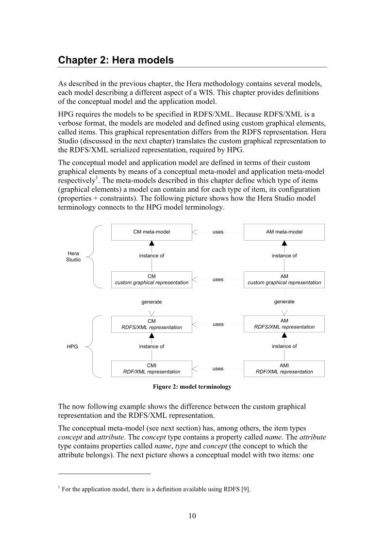
The conceptual model and application model are defined in terms of their custom graphical elements by means of a conceptual meta-model and application meta-model respectively1. The meta-models described in this chapter define which type of items (graphical elements) a model can contain and for each type of item, its configuration (properties + constraints). The following picture shows how the Hera Studio model terminology connects to the HPG model terminology.
CM meta-model
CMcustom graphical representation
CMRDFS/XML representation
uses
CMIRDF/XML representation
instance ofHera Studio
HPG
AM meta-model
AMcustom graphical representation
instance of
uses
instance of
AMRDFS/XML representation
AMIRDF/XML representation
instance of
uses
uses
generate generate
Figure 2: model terminology
The now following example shows the difference between the custom graphical representation and the RDFS/XML representation.
The conceptual meta-model (see next section) has, among others, the item types concept and attribute. The concept type contains a property called name. The attribute type contains properties called name, type and concept (the concept to which the attribute belongs). The next picture shows a conceptual model with two items: one
1 For the application model, there is a definition available using RDFS [9].
10
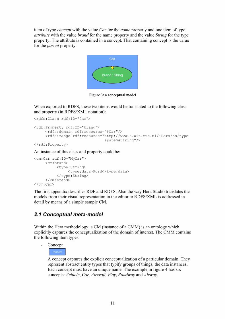
item of type concept with the value Car for the name property and one item of type attribute with the value brand for the name property and the value String for the type property. The attribute is contained in a concept. That containing concept is the value for the parent property.
Figure 3: a conceptual model
When exported to RDFS, these two items would be translated to the following class and property (in RDFS/XML notation): <rdfs:Class rdf:ID="Car"> <rdf:Property rdf:ID="brand"> <rdfs:domain rdf:resource="#Car"/> <rdfs:range rdf:resource="http://wwwis.win.tue.nl/~Hera/ns/type system#String"/> </rdf:Property>
An instance of this class and property could be: <cm:Car rdf:ID="MyCar"> <cm:brand> <type:String> <type:data>Ford</type:data> </type:String> </cm:brand> </cm:Car>
The first appendix describes RDF and RDFS. Also the way Hera Studio translates the models from their visual representation in the editor to RDFS/XML is addressed in detail by means of a simple sample CM.
2.1 Conceptual meta-model
Within the Hera methodology, a CM (instance of a CMM) is an ontology which explicitly captures the conceptualization of the domain of interest. The CMM contains the following item types:
- Concept
A concept captures the explicit conceptualization of a particular domain. They represent abstract entity types that typify groups of things, the data instances. Each concept must have an unique name. The example in figure 4 has six concepts: Vehicle, Car, Aircraft, Way, Roadway and Airway.
11
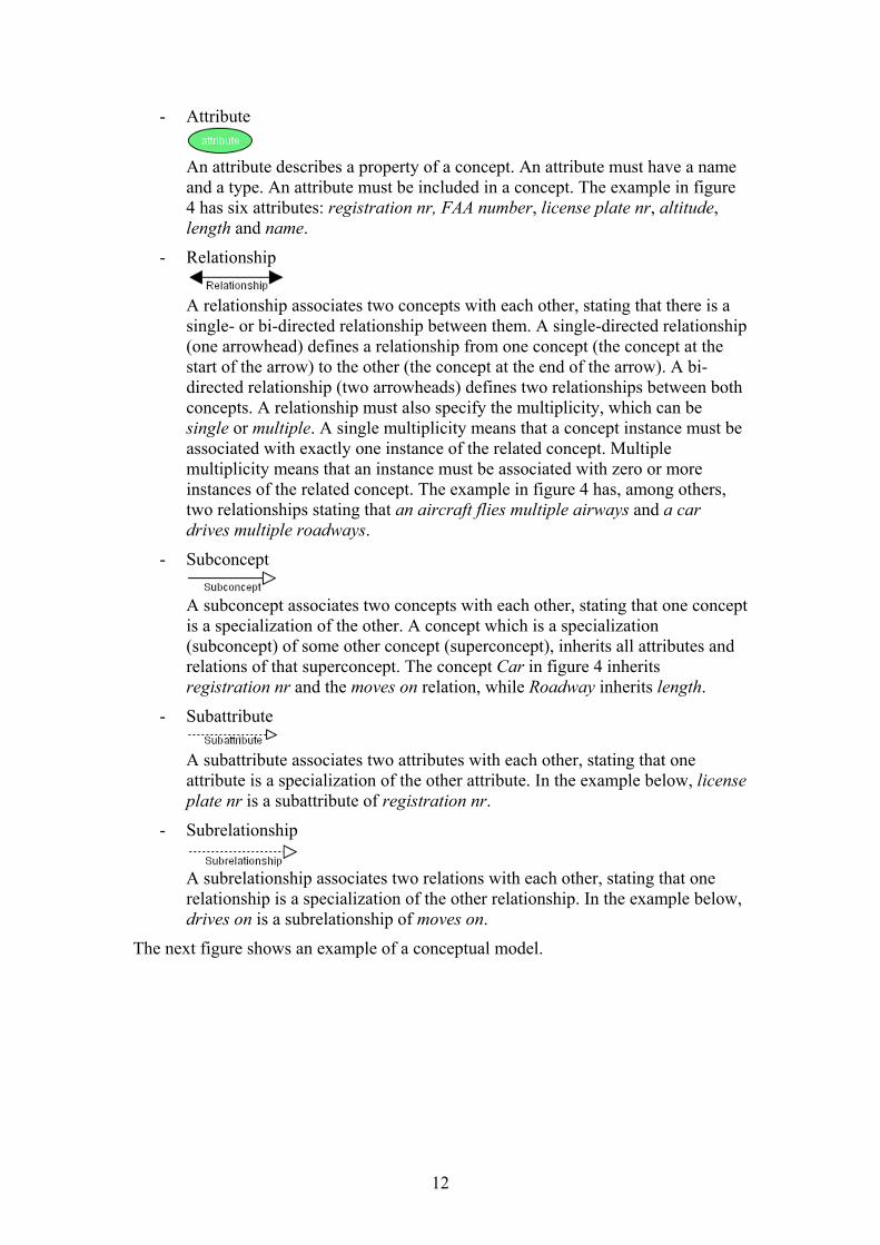
- Attribute
An attribute describes a property of a concept. An attribute must have a name and a type. An attribute must be included in a concept. The example in figure 4 has six attributes: registration nr, FAA number, license plate nr, altitude, length and name.
- Relationship
A relationship associates two concepts with each other, stating that there is a single- or bi-directed relationship between them. A single-directed relationship (one arrowhead) defines a relationship from one concept (the concept at the start of the arrow) to the other (the concept at the end of the arrow). A bi-directed relationship (two arrowheads) defines two relationships between both concepts. A relationship must also specify the multiplicity, which can be single or multiple. A single multiplicity means that a concept instance must be associated with exactly one instance of the related concept. Multiple multiplicity means that an instance must be associated with zero or more instances of the related concept. The example in figure 4 has, among others, two relationships stating that an aircraft flies multiple airways and a car drives multiple roadways.
- Subconcept
A subconcept associates two concepts with each other, stating that one concept is a specialization of the other. A concept which is a specialization (subconcept) of some other concept (superconcept), inherits all attributes and relations of that superconcept. The concept Car in figure 4 inherits registration nr and the moves on relation, while Roadway inherits length.
- Subattribute
A subattribute associates two attributes with each other, stating that one attribute is a specialization of the other attribute. In the example below, license plate nr is a subattribute of registration nr.
- Subrelationship
A subrelationship associates two relations with each other, stating that one relationship is a specialization of the other relationship. In the example below, drives on is a subrelationship of moves on.
The next figure shows an example of a conceptual model.
12
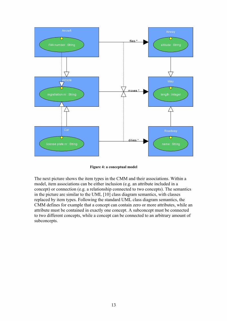
Figure 4: a conceptual model
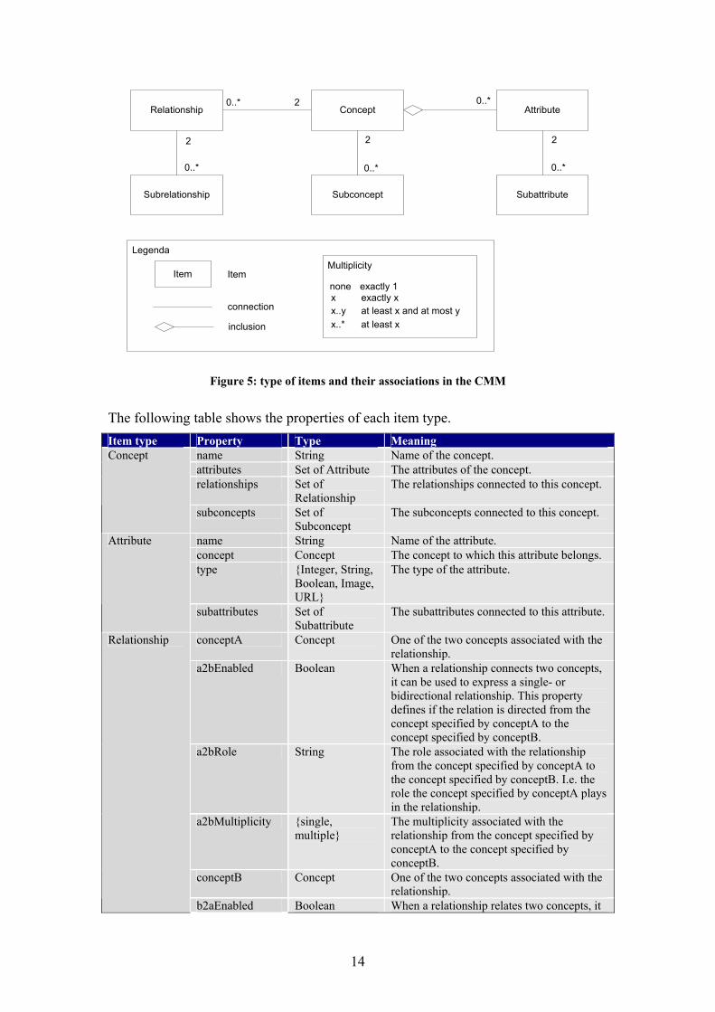
The next picture shows the item types in the CMM and their associations. Within a model, item associations can be either inclusion (e.g. an attribute included in a concept) or connection (e.g. a relationship connected to two concepts). The semantics in the picture are similar to the UML [10] class diagram semantics, with classes replaced by item types. Following the standard UML class diagram semantics, the CMM defines for example that a concept can contain zero or more attributes, while an attribute must be contained in exactly one concept. A subconcept must be connected to two different concepts, while a concept can be connected to an arbitrary amount of subconcepts.
13
2
2 2
Relationship Concept Attribute
Subconcept Subattribute
Legenda
Item Item
inclusion
Multiplicity
x..y at least x and at most y
0..*
0..*
0..*
0..*
x..* at least x
connectionx exactly x
2
Subrelationship
0..*
none exactly 1
Figure 5: type of items and their associations in the CMM
The following table shows the properties of each item type. Item type Property Type Meaning
name String Name of the concept. attributes Set of Attribute The attributes of the concept. relationships Set of
Relationship The relationships connected to this concept.
Concept
subconcepts Set of Subconcept
The subconcepts connected to this concept.
name String Name of the attribute. concept Concept The concept to which this attribute belongs. type {Integer, String,
Boolean, Image, URL}
The type of the attribute.
Attribute
subattributes Set of Subattribute
The subattributes connected to this attribute.
conceptA Concept One of the two concepts associated with the relationship.
a2bEnabled Boolean When a relationship connects two concepts, it can be used to express a single- or bidirectional relationship. This property defines if the relation is directed from the concept specified by conceptA to the concept specified by conceptB.
a2bRole String The role associated with the relationship from the concept specified by conceptA to the concept specified by conceptB. I.e. the role the concept specified by conceptA plays in the relationship.
a2bMultiplicity {single, multiple}
The multiplicity associated with the relationship from the concept specified by conceptA to the concept specified by conceptB.
conceptB Concept One of the two concepts associated with the relationship.
Relationship
b2aEnabled Boolean When a relationship relates two concepts, it
14
can be used to express a single- or bidirectional relationship. This property defines if the relation is directed from the concept specified by conceptB to the concept specified by conceptA.
b2aRole String The role associated with the relationship from the concept specified by conceptB to the concept specified by conceptA. I.e. the role the concept specified by conceptB plays in the relationship.
b2aMultiplicity {single, multiple}
The multiplicity associated with the relationship from the concept specified by conceptA to the concept specified by conceptA.
subrelationships Set of Subrelationship
The subrelationships connected to this relationship
superconcept Concept The concept which is a generalization of the concept specified by subconcept. This is the concept from which the concept specified by subconcept inherits the attributes.
Subconcept
subconcept Concept The concept which is a specialization of the concept specified by superconcept. This is the concept which inherits the attributes from the concept specified by superconcept.
superrelationship Relationship The relationship which is a generalization of the concept specified by subrelationship.
Subrelationship
subrelationship Relationship The relationship which is a specialization of the concept specified by superrelationship.
superattribute Attribute The attribute which is a generalization of the concept specified by subattribute.
Subattribute
subattribute Attribute The attribute which is a specialization of the concept specified by superattribute.
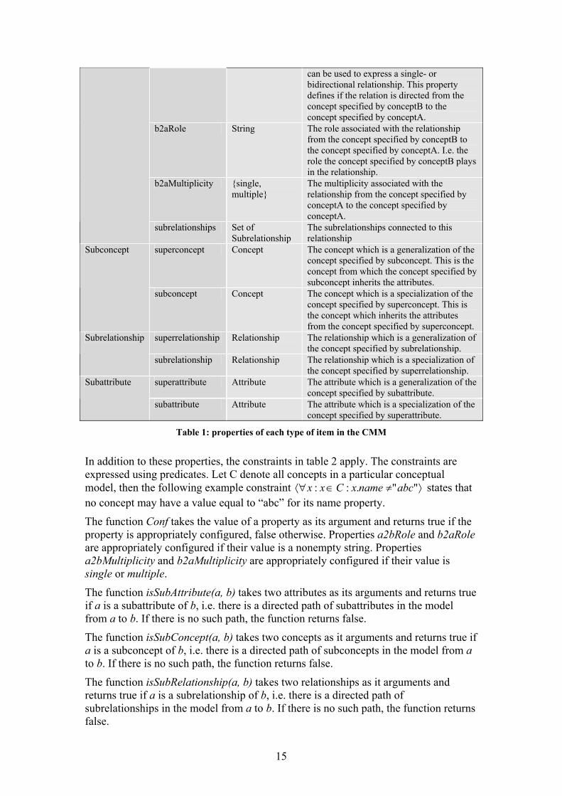
Table 1: properties of each type of item in the CMM
In addition to these properties, the constraints in table 2 apply. The constraints are expressed using predicates. Let C denote all concepts in a particular conceptual model, then the following example constraint ⟩≠∈⟨∀ "".:: abcnamexCxx states that no concept may have a value equal to “abc” for its name property.
The function Conf takes the value of a property as its argument and returns true if the property is appropriately configured, false otherwise. Properties a2bRole and b2aRole are appropriately configured if their value is a nonempty string. Properties a2bMultiplicity and b2aMultiplicity are appropriately configured if their value is single or multiple.
The function isSubAttribute(a, b) takes two attributes as its arguments and returns true if a is a subattribute of b, i.e. there is a directed path of subattributes in the model from a to b. If there is no such path, the function returns false.
The function isSubConcept(a, b) takes two concepts as it arguments and returns true if a is a subconcept of b, i.e. there is a directed path of subconcepts in the model from a to b. If there is no such path, the function returns false.
The function isSubRelationship(a, b) takes two relationships as it arguments and returns true if a is a subrelationship of b, i.e. there is a directed path of subrelationships in the model from a to b. If there is no such path, the function returns false.
15
Let the following items belong to a particular conceptual model:
A : Attributes C : Concepts R : Relationships SA : Subattributes SC : Subconcepts Item Constraint
Name must be unique:
⟩=⇒=∈∀⟨ yxy.namex.name:Cyx,:yx,
Concept
No two attributes with the same name:
⟩⟩=⇒=∈⟨∀∈∀⟨ zyz.name)(y.name:esx.attributzy,:zy,:Cx:x
Must be single- or bidirectional:
⟩∨∈⟨∀ edx.b2aEnabledx.a2bEnabl:Rx:x
Relationship
A directed relation must have a role and multiplicity specified:
⟩∧⇒∧∧⇒
∈⟨∀
ty)))Multipliciconf(x.b2aaRole)(conf(x.b2led(x.b2aEnabty)))Multipliciconf(x.a2bbRole)(conf(x.a2led(x.a2bEnab
:Rx:x
No double subattributes:
( ) ⟩=⇒=∧=∈⟨∀
yxbutey.subattributex.subattriributey.superattributex.superatt:SAyx,:yx,
No cyclic inheritance:
⟩¬⇒∈⟨∀ x)bute(y,isSubAttriy)bute(x,isSubAttri:SAyx,:yx,
Subattribute and superattribute must be different:
⟩≠∈⟨∀ ributex.superatt butex.subattri:SAx:x
Subattribute
The concept to which the subattribute belongs, must be a subconcept of the concept to which the superattribute belongs:
⟩∈⟨∀ oncept)ttribute.c x.superancept,tribute.copt(x.subatisSubConce:SAx:x
No double subconcepts:
( ) ⟩=⇒=∧=∈⟨∀
yxpty.subconceptx.subconcecepty.superconceptx.supercon:SCyx,:yx,
No cyclic inheritance:
⟩¬⇒∈⟨∀ x)pt(y,isSubConcey)pt(x,isSubConce:SCyx,:yx,
Subconcept
Subconcept and superconcept must be different:
⟩≠∈⟨∀ ceptx.superconpt x.subconce:SCx:x
Subrelation No double subrelationships:
16
⟩=⇒=∧=
∈⟨∀
⎟⎠⎞⎜
⎝⎛ yxionshipy.subrelationshipx.subrelat
ationshipy.superrelationshipx.superrel:SRyx,:yx,
No cyclic inheritance:
⟩¬⇒∈⟨∀
x)ionship(y,isSubRelaty)ionship(x,isSubRelat:SRyx,:yx,
Subrelation and superrelation must be different:
⟩≠∈⟨∀ ationshipx.superrel ionshipx.subrelat:SRx:x
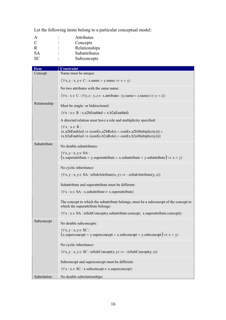
Table 2: CMM constraints
2.2 Application meta-model
Within the Hera methodology, an AM (instance of a AMM) describes a navigational view of the CM, i.e. it groups parts of the CM into navigational units called slices and connects them with some navigational primitives. The AMM contains the following item types:
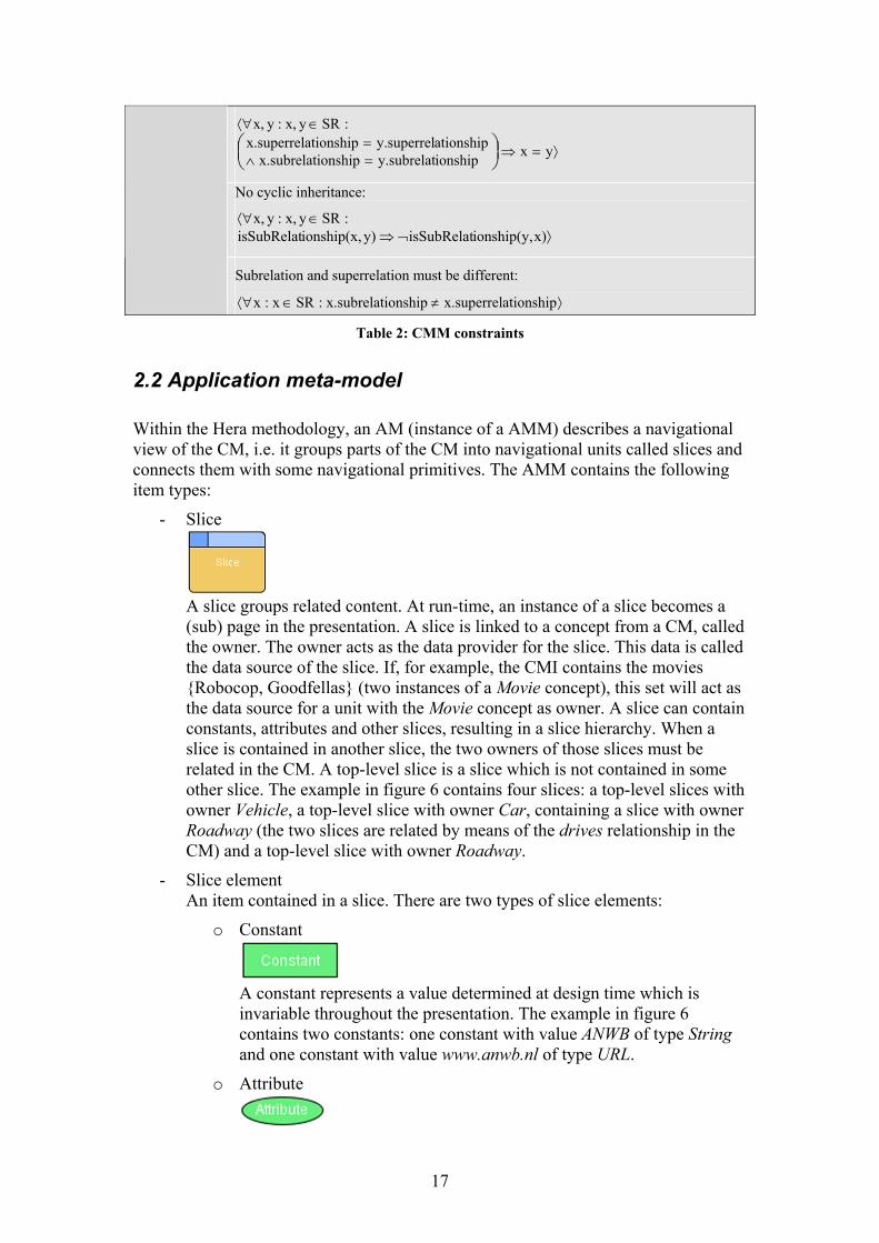
- Slice
A slice groups related content. At run-time, an instance of a slice becomes a (sub) page in the presentation. A slice is linked to a concept from a CM, called the owner. The owner acts as the data provider for the slice. This data is called the data source of the slice. If, for example, the CMI contains the movies {Robocop, Goodfellas} (two instances of a Movie concept), this set will act as the data source for a unit with the Movie concept as owner. A slice can contain constants, attributes and other slices, resulting in a slice hierarchy. When a slice is contained in another slice, the two owners of those slices must be related in the CM. A top-level slice is a slice which is not contained in some other slice. The example in figure 6 contains four slices: a top-level slices with owner Vehicle, a top-level slice with owner Car, containing a slice with owner Roadway (the two slices are related by means of the drives relationship in the CM) and a top-level slice with owner Roadway.
- Slice element An item contained in a slice. There are two types of slice elements:
o Constant
A constant represents a value determined at design time which is invariable throughout the presentation. The example in figure 6 contains two constants: one constant with value ANWB of type String and one constant with value www.anwb.nl of type URL.
o Attribute
17
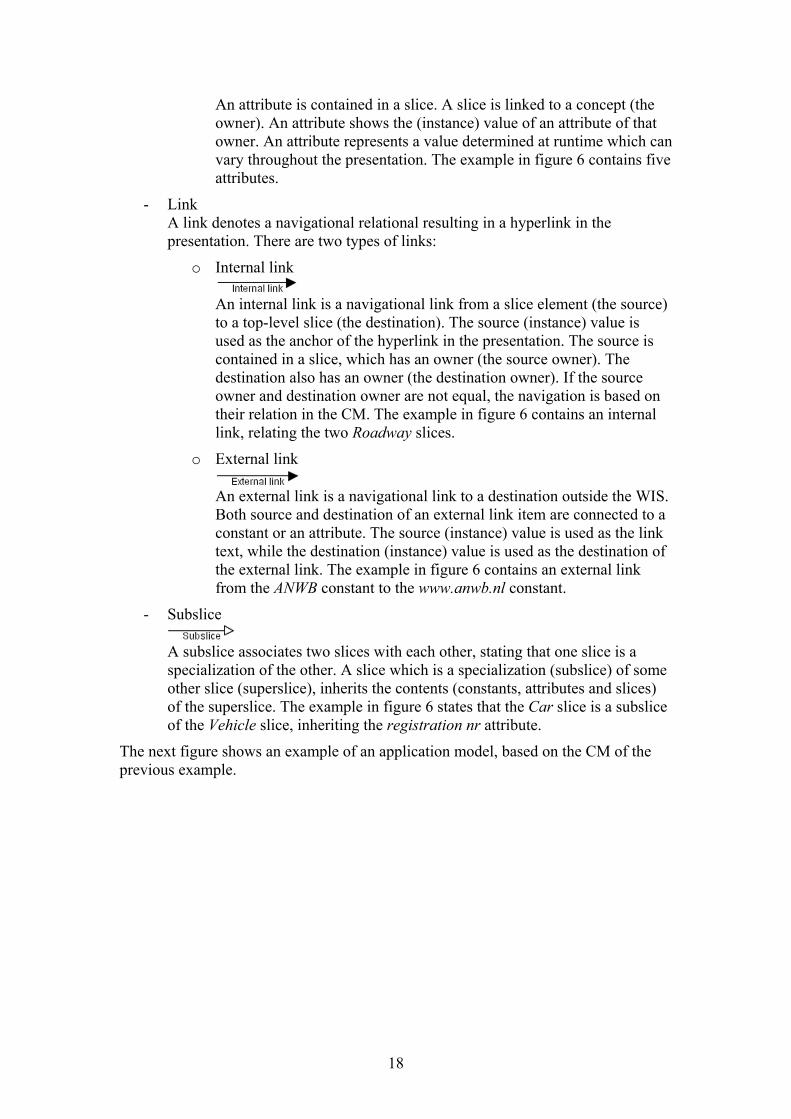
An attribute is contained in a slice. A slice is linked to a concept (the owner). An attribute shows the (instance) value of an attribute of that owner. An attribute represents a value determined at runtime which can vary throughout the presentation. The example in figure 6 contains five attributes.
- Link A link denotes a navigational relational resulting in a hyperlink in the presentation. There are two types of links:
o Internal link
An internal link is a navigational link from a slice element (the source) to a top-level slice (the destination). The source (instance) value is used as the anchor of the hyperlink in the presentation. The source is contained in a slice, which has an owner (the source owner). The destination also has an owner (the destination owner). If the source owner and destination owner are not equal, the navigation is based on their relation in the CM. The example in figure 6 contains an internal link, relating the two Roadway slices.
o External link
An external link is a navigational link to a destination outside the WIS. Both source and destination of an external link item are connected to a constant or an attribute. The source (instance) value is used as the link text, while the destination (instance) value is used as the destination of the external link. The example in figure 6 contains an external link from the ANWB constant to the www.anwb.nl constant.
- Subslice
A subslice associates two slices with each other, stating that one slice is a specialization of the other. A slice which is a specialization (subslice) of some other slice (superslice), inherits the contents (constants, attributes and slices) of the superslice. The example in figure 6 states that the Car slice is a subslice of the Vehicle slice, inheriting the registration nr attribute.
The next figure shows an example of an application model, based on the CM of the previous example.
18
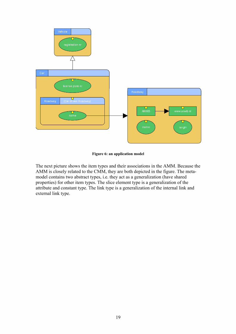
Figure 6: an application model
The next picture shows the item types and their associations in the AMM. Because the AMM is closely related to the CMM, they are both depicted in the figure. The meta-model contains two abstract types, i.e. they act as a generalization (have shared properties) for other item types. The slice element type is a generalization of the attribute and constant type. The link type is a generalization of the internal link and external link type.
19
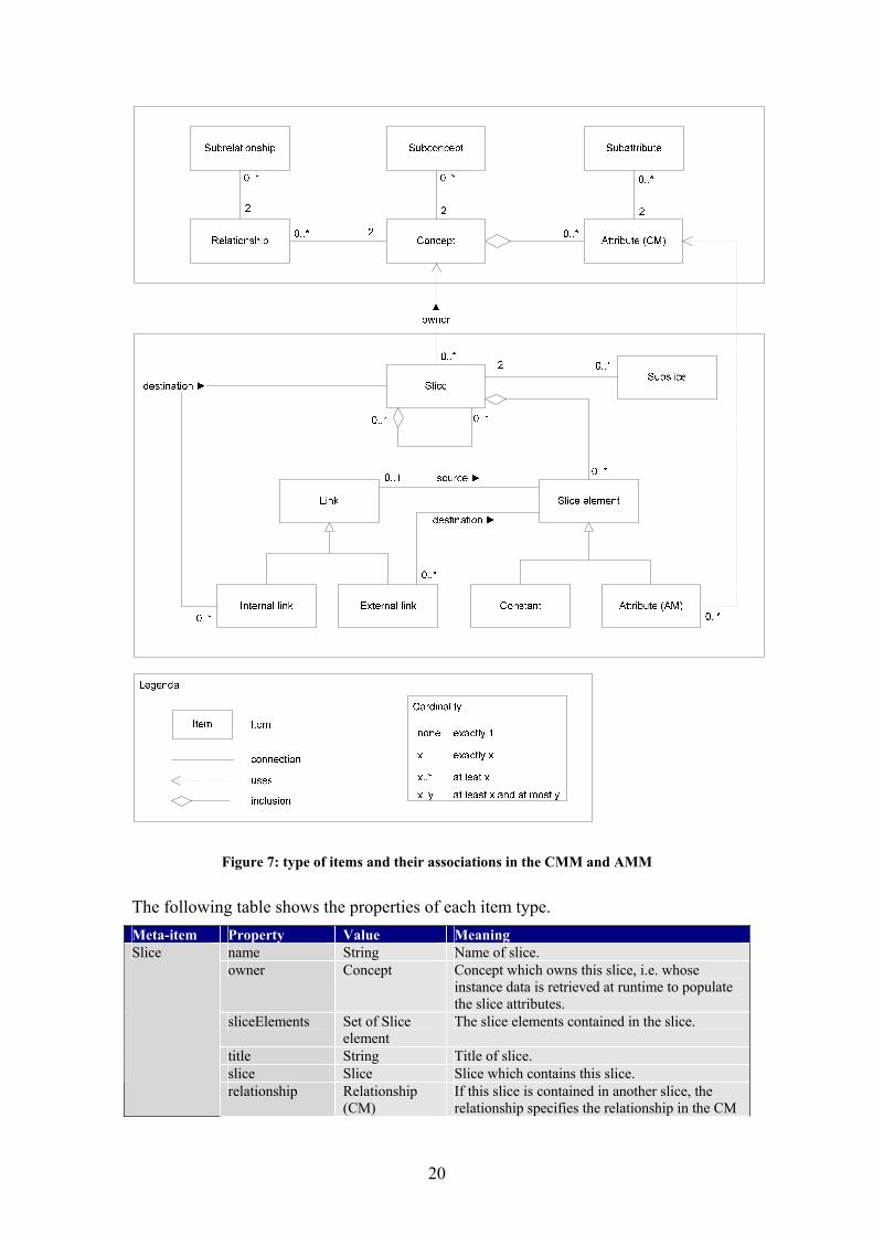
Figure 7: type of items and their associations in the CMM and AMM
The following table shows the properties of each item type. Meta-item Property Value Meaning
name String Name of slice. owner Concept Concept which owns this slice, i.e. whose
instance data is retrieved at runtime to populate the slice attributes.
sliceElements Set of Slice element
The slice elements contained in the slice.
title String Title of slice. slice Slice Slice which contains this slice.
Slice
relationship Relationship (CM)
If this slice is contained in another slice, the relationship specifies the relationship in the CM
20
of the two owners. mainEntryPoint Boolean A slice is the main entry point if it is the first
slice in the presentation. subSlices Set of Subslice Subslices connected to this slice. internalLinks Set of Internal
link Internal links connected this slice.
Link source Slice element The slice element acting as the source of the link.
Internal link destination Slice The slice acting as the destination of the internal link.
External ink destination Slice element The slice element whose URL (instance) value acts as the destination of the external link.
Slice elements
slice Slice Slice to which this slice element belongs.
name String Name of constant. This value is used in the RDFS export.
value String Value of constant. type {Integer,
String, Boolean, Image, URL}
Type of constant.
description String Description of constant.
Constant
externalLinks Set of External link
External links connected to this constant.
subslice Slice The slice which inherits the content (constants, attributes and slices) of the slice specified by superslice.
Subslice
superslice Slice The slice from which the slice specified by subslice inherits the content (constants, attributes and slices)
slice Slice Slice to which this attribute belongs. Attribute attribute Attribute (CM) An attribute is contained in a slice, which is
linked to a concept (the owner). This property specifies from which attribute of the owner the (instance) value is shown.
Table 3: Properties of each type of item in the AMM
In addition, the constraints in Table 4 apply.
The function isSubslice(a, b) takes two slices as it arguments and returns true if a is a subslice of b, i.e. there is a directed path of subslices in the model from a to b. If there is no such path, the function returns false.
Let the following items belong to a particular conceptual model and application model:
AAM : Attributes (application model) ACM : Attributes (conceptual model) CC : Concepts CS : Constants EL : External links IL : Internal links L : Links (EL + IL) R : Relationships S : Slices SS : Subslices
21
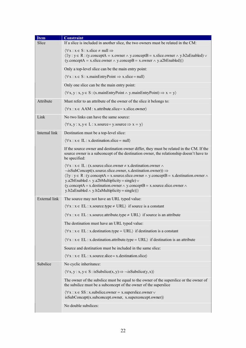
Item Constraint
If a slice is included in another slice, the two owners must be related in the CM:
⟩⟩∧=∧=∨∧=∧=∈⟨∃
⇒≠∈⟨∀
ed)y.a2bEnablx.ownery.concepBnerx.slice.owA(y.concepted)y.b2aEnablnerx.slice.owy.conceptBx.ownerA(y.concept:Ry:y
nullx.slice:Sx:x
Only a top-level slice can be the main entry point:
⟩=⇒∈⟨∀ null x.sliceyPointx.mainEntr:Sx:x
Slice
Only one slice can be the main entry point:
⟩=⇒∧∈⟨∀ yxyPoint)y.mainEntrryPoint(x.mainEnt:Syx,:yx,
Attribute Must refer to an attribute of the owner of the slice it belongs to:
⟩=∈⟨∀ wner x.slice.o e.slicex.attribut:AAMx:x
Link No two links can have the same source:
⟩=⇒=∈⟨∀ yxy.source x.source:Lyx,:yx,
Destination must be a top-level slice:
⟩=∈⟨∀ nullion.slicex.destinat:ILx:x
Internal link
If the source owner and destination owner differ, they must be related in the CM. If the source owner is a subconcept of the destination owner, the relationship doesn’t have to be specified:
⟩⟩=∧∧=∧=
∨=∧∧=∧=∈⟨∃
⇒¬∧≠∈⟨∀
single) plicity y.b2aMultiedy.b2aEnabllice.ownerx.source.sy.conceptB tion.owner x.destinaA (y.concept
single) plicity y.a2bMultiedy.a2bEnablion.ownerx.destinaty.conceptBr slice.owne x.source.A (y.concept :Ry:y
))tion.owner x.destinaner,e.slice.owpt(x.sourcisSubConcetion.owner x.destinar slice.owne(x.source.:ILx:x
The source may not have an URL typed value:
⟩≠∈⟨∀ URLypex.source.t:ELx:x if source is a constant
⟩≠∈⟨∀ URLypettribute.tx.source.a:ELx:x if source is an attribute
The destination must have an URL typed value:
⟩=∈⟨∀ URLion.typex.destinat:ELx:x if destination is a constant
⟩=∈⟨∀ URLute.typeion.attribx.destinat:ELx:x if destination is an attribute
External link
Source and destination must be included in the same slice:
⟩=∈⟨∀ tion.slice x.destina licex.source.s:ELx:x
No cyclic inheritance:
⟩¬⇒∈⟨∀ x)(y,isSubslice y)(x,isSubslice:Syx,:yx,
The owner of the subslice must be equal to the owner of the superslice or the owner of the subslice must be a subconcept of the owner of the superslice
⟩∨=∈⟨∀
er)oncept.own x.supercr,ncept.ownept(x.subcoisSubConcece.owner x.supersli.ownerx.subslice:SSx:x
Subslice
No double subslices:
22

⟩=⇒=∧=∈⟨∀
yxce)u.superslix.subslicey.subslicee(x.subslic:SSyx,:yx,
Subslice and superslice must differ:
⟩≠∈⟨∀ cex.superslix.subslice:SSx:x
Table 4: AMM constraints
Note that there is no formal definition of the CM using RDFS. A definition of the AM using RDFS can be found in [9]. The meta-models provided in this chapter give precise definitions of the CM and AM in terms of the visual primitives used by the editors in Hera Studio, abstracting away from RDFS peculiarities. The provided meta-models are thus format independent.
23
Chapter 3: Hera Studio
As discussed in the first chapter, the goal of the project was to develop an editor application, called Hera Studio. This chapter discusses the Hera Studio application. First the requirements are listed, after which the current program implementation is described. How to use the application is explained in the last section of this chapter, using an illustrated tutorial.
3.1 Requirements
This section lists the functional and non-functional requirements. Functional requirements are those things the system is supposed to do. The non-functional requirements state additional conditions beyond the functional aspects of the system.
3.1.1 Functional requirements
The next list shows the functional requirements.
- Model editors To facilitate the AWIS engineer in applying the Hera methodology, the Hera models should be created in a graphical environment. The existing Visio editors sketch the idea. The new model editors should overcome the functional shortcomings of the old editors. The next list shows those functional shortcomings:
o Model constructs not supported. Hera Studio should support all constructs of the conceptual model and application model, including inheritance, arbitrary slice hierarchies and external linking.
o One editor for each type of model. Hera Studio should be a single program which integrates a CM editor, an AM editor and future editors in one “studio”.
o Model constraints (described in the previous chapter) are not checked during editing. Hera Studio should disallow particular constructs during editing. You should not be able, for example, to create a cycle in the concept inheritance chain. Constrains which cannot be checked while editing must be checked during the export procedure (e.g. an attribute which is not included in a concept).
- Export project It must be possible to export the models to RDFS/XML in order to work with the HPG applications.
3.1.2 Non-functional requirements
The next list shows the non-functional requirements:
24
- Java The application must be implemented in Java. Furthermore, the usage of open source is preferred.
- Extensible Hera Studio shall be further developed in the near future. Program design must be such that additions, e.g. including a new model type, can be made with relatively little programming effort.
- Usable Hera Studio must be easy to learn and use.
3.2 Using Hera Studio
This section describes Hera Studio and how to use it. First the user interface is explained after which a small tutorial is given. Hera Studio is a Java application and in order to run it, the Java Runtime Environment [11] (version 1.4 or later) must be installed.
3.2.1 The user interface
This section describes the user interface of Hera Studio. When starting Hera Studio, a default project is created. A project consists of models and can be saved to disk. The next picture shows the main screen of Hera Studio when a project is active. Here, an application model is visible.
25
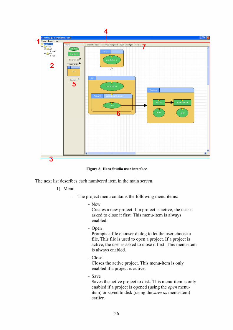
Figure 8: Hera Studio user interface
The next list describes each numbered item in the main screen.
1) Menu
- The project menu contains the following menu items:
- New Creates a new project. If a project is active, the user is asked to close it first. This menu-item is always enabled.
- Open Prompts a file chooser dialog to let the user choose a file. This file is used to open a project. If a project is active, the user is asked to close it first. This menu-item is always enabled.
- Close Closes the active project. This menu-item is only enabled if a project is active.
- Save Saves the active project to disk. This menu-item is only enabled if a project is opened (using the open menu-item) or saved to disk (using the save as menu-item) earlier.
26
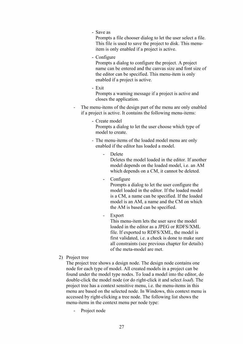
- Save as Prompts a file chooser dialog to let the user select a file. This file is used to save the project to disk. This menu-item is only enabled if a project is active.
- Configure Prompts a dialog to configure the project. A project name can be entered and the canvas size and font size of the editor can be specified. This menu-item is only enabled if a project is active.
- Exit Prompts a warning message if a project is active and closes the application.
- The menu-items of the design part of the menu are only enabled if a project is active. It contains the following menu-items:
- Create model Prompts a dialog to let the user choose which type of model to create.
- The menu-items of the loaded model menu are only enabled if the editor has loaded a model.
- Delete Deletes the model loaded in the editor. If another model depends on the loaded model, i.e. an AM which depends on a CM, it cannot be deleted.
- Configure Prompts a dialog to let the user configure the model loaded in the editor. If the loaded model is a CM, a name can be specified. If the loaded model is an AM, a name and the CM on which the AM is based can be specified.
- Export This menu-item lets the user save the model loaded in the editor as a JPEG or RDFS/XML file. If exported to RDFS/XML, the model is first validated, i.e. a check is done to make sure all constraints (see previous chapter for details) of the meta-model are met.
2) Project tree The project tree shows a design node. The design node contains one node for each type of model. All created models in a project can be found under the model type nodes. To load a model into the editor, do double-click the model node (or do right-click it and select load). The project tree has a context sensitive menu, i.e. the menu-items in this menu are based on the selected node. In Windows, this context menu is accessed by right-clicking a tree node. The following list shows the menu-items in the context menu per node type:
- Project node
27
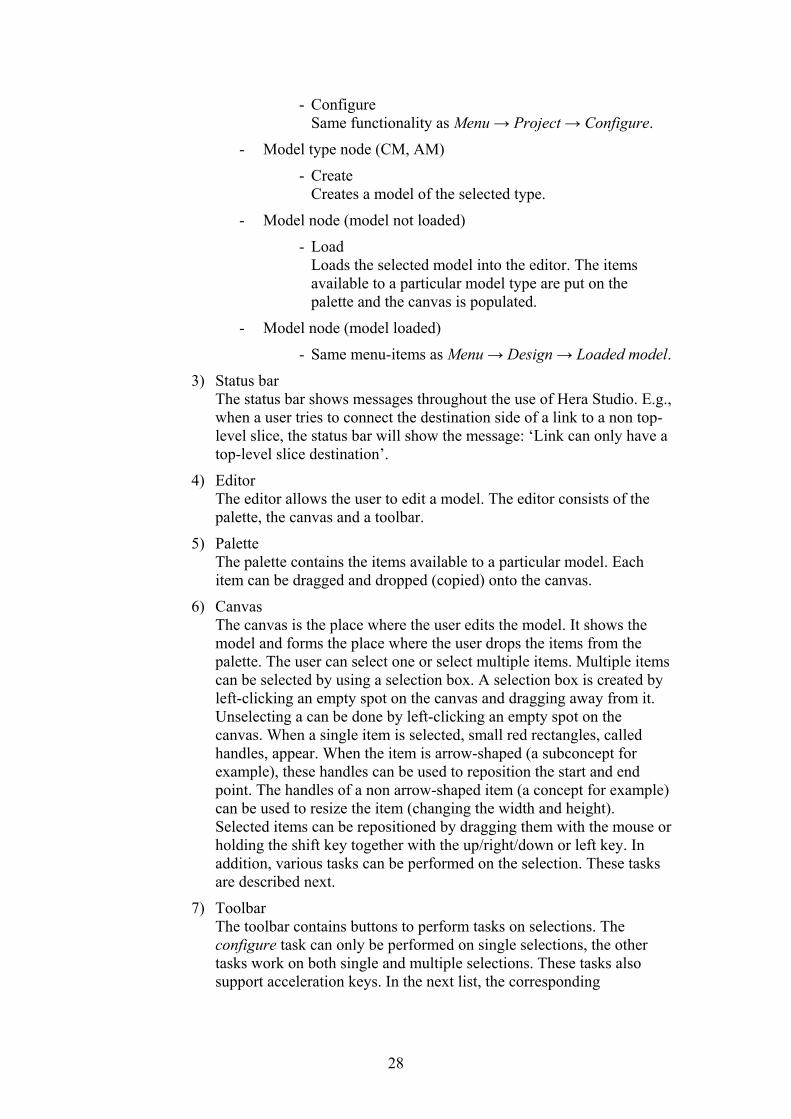
- Configure Same functionality as Menu → Project → Configure.
- Model type node (CM, AM)
- Create Creates a model of the selected type.
- Model node (model not loaded)
- Load Loads the selected model into the editor. The items available to a particular model type are put on the palette and the canvas is populated.
- Model node (model loaded)
- Same menu-items as Menu → Design → Loaded model.
3) Status bar The status bar shows messages throughout the use of Hera Studio. E.g., when a user tries to connect the destination side of a link to a non top-level slice, the status bar will show the message: ‘Link can only have a top-level slice destination’.
4) Editor The editor allows the user to edit a model. The editor consists of the palette, the canvas and a toolbar.
5) Palette The palette contains the items available to a particular model. Each item can be dragged and dropped (copied) onto the canvas.
6) Canvas The canvas is the place where the user edits the model. It shows the model and forms the place where the user drops the items from the palette. The user can select one or select multiple items. Multiple items can be selected by using a selection box. A selection box is created by left-clicking an empty spot on the canvas and dragging away from it. Unselecting a can be done by left-clicking an empty spot on the canvas. When a single item is selected, small red rectangles, called handles, appear. When the item is arrow-shaped (a subconcept for example), these handles can be used to reposition the start and end point. The handles of a non arrow-shaped item (a concept for example) can be used to resize the item (changing the width and height). Selected items can be repositioned by dragging them with the mouse or holding the shift key together with the up/right/down or left key. In addition, various tasks can be performed on the selection. These tasks are described next.
7) Toolbar The toolbar contains buttons to perform tasks on selections. The configure task can only be performed on single selections, the other tasks work on both single and multiple selections. These tasks also support acceleration keys. In the next list, the corresponding
28
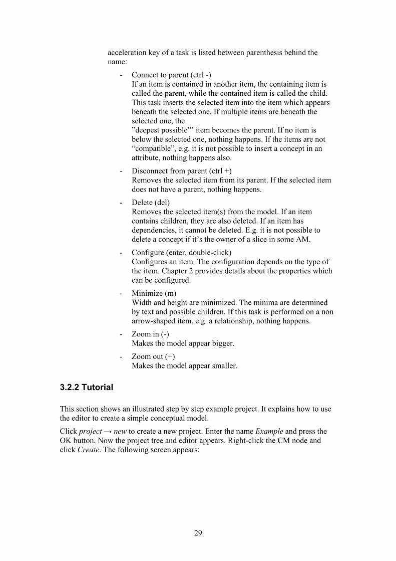
acceleration key of a task is listed between parenthesis behind the name:
- Connect to parent (ctrl -) If an item is contained in another item, the containing item is called the parent, while the contained item is called the child. This task inserts the selected item into the item which appears beneath the selected one. If multiple items are beneath the selected one, the ”deepest possible”’ item becomes the parent. If no item is below the selected one, nothing happens. If the items are not “compatible”, e.g. it is not possible to insert a concept in an attribute, nothing happens also.
- Disconnect from parent (ctrl +) Removes the selected item from its parent. If the selected item does not have a parent, nothing happens.
- Delete (del) Removes the selected item(s) from the model. If an item contains children, they are also deleted. If an item has dependencies, it cannot be deleted. E.g. it is not possible to delete a concept if it’s the owner of a slice in some AM.
- Configure (enter, double-click) Configures an item. The configuration depends on the type of the item. Chapter 2 provides details about the properties which can be configured.
- Minimize (m) Width and height are minimized. The minima are determined by text and possible children. If this task is performed on a non arrow-shaped item, e.g. a relationship, nothing happens.
- Zoom in (-) Makes the model appear bigger.
- Zoom out (+) Makes the model appear smaller.
3.2.2 Tutorial
This section shows an illustrated step by step example project. It explains how to use the editor to create a simple conceptual model.
Click project → new to create a new project. Enter the name Example and press the OK button. Now the project tree and editor appears. Right-click the CM node and click Create. The following screen appears:
29
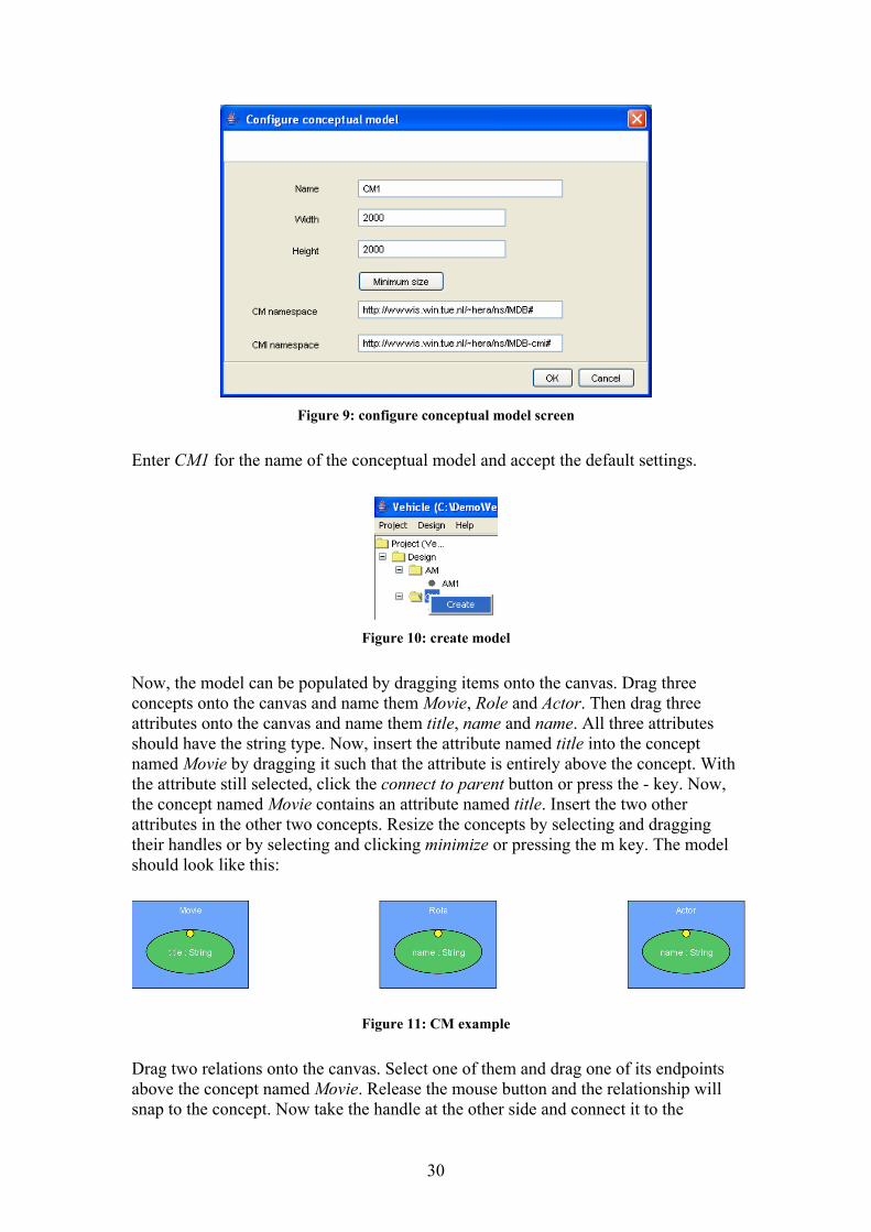
Figure 9: configure conceptual model screen
Enter CM1 for the name of the conceptual model and accept the default settings.
Figure 10: create model
Now, the model can be populated by dragging items onto the canvas. Drag three concepts onto the canvas and name them Movie, Role and Actor. Then drag three attributes onto the canvas and name them title, name and name. All three attributes should have the string type. Now, insert the attribute named title into the concept named Movie by dragging it such that the attribute is entirely above the concept. With the attribute still selected, click the connect to parent button or press the - key. Now, the concept named Movie contains an attribute named title. Insert the two other attributes in the other two concepts. Resize the concepts by selecting and dragging their handles or by selecting and clicking minimize or pressing the m key. The model should look like this:
Figure 11: CM example
Drag two relations onto the canvas. Select one of them and drag one of its endpoints above the concept named Movie. Release the mouse button and the relationship will snap to the concept. Now take the handle at the other side and connect it to the
30
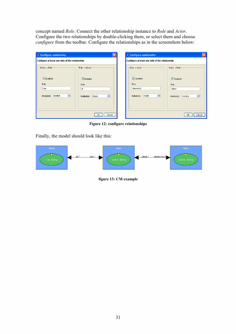
concept named Role. Connect the other relationship instance to Role and Actor. Configure the two relationships by double-clicking them, or select them and choose configure from the toolbar. Configure the relationships as in the screenshots below:
Figure 12: configure relationships
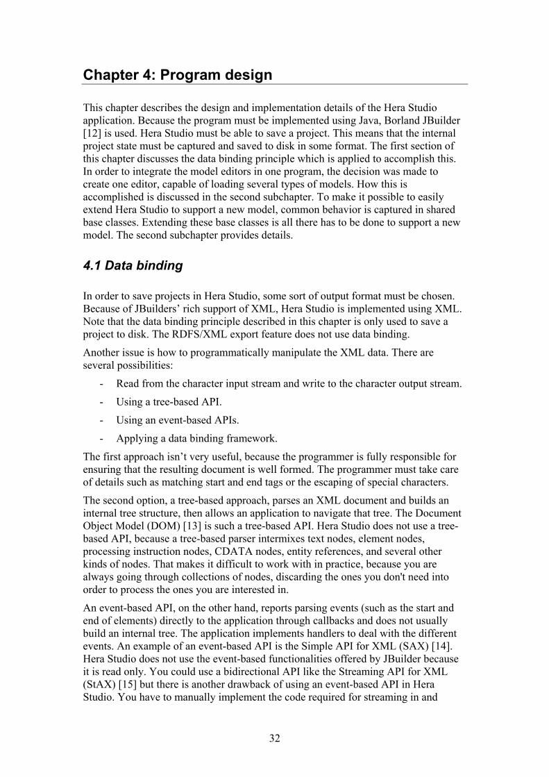
Finally, the model should look like this:
figure 13: CM example
31
Chapter 4: Program design
This chapter describes the design and implementation details of the Hera Studio application. Because the program must be implemented using Java, Borland JBuilder [12] is used. Hera Studio must be able to save a project. This means that the internal project state must be captured and saved to disk in some format. The first section of this chapter discusses the data binding principle which is applied to accomplish this. In order to integrate the model editors in one program, the decision was made to create one editor, capable of loading several types of models. How this is accomplished is discussed in the second subchapter. To make it possible to easily extend Hera Studio to support a new model, common behavior is captured in shared base classes. Extending these base classes is all there has to be done to support a new model. The second subchapter provides details.
4.1 Data binding
In order to save projects in Hera Studio, some sort of output format must be chosen. Because of JBuilders’ rich support of XML, Hera Studio is implemented using XML. Note that the data binding principle described in this chapter is only used to save a project to disk. The RDFS/XML export feature does not use data binding.
Another issue is how to programmatically manipulate the XML data. There are several possibilities:
- Read from the character input stream and write to the character output stream.
- Using a tree-based API.
- Using an event-based APIs.
- Applying a data binding framework.
The first approach isn’t very useful, because the programmer is fully responsible for ensuring that the resulting document is well formed. The programmer must take care of details such as matching start and end tags or the escaping of special characters.
The second option, a tree-based approach, parses an XML document and builds an internal tree structure, then allows an application to navigate that tree. The Document Object Model (DOM) [13] is such a tree-based API. Hera Studio does not use a tree-based API, because a tree-based parser intermixes text nodes, element nodes, processing instruction nodes, CDATA nodes, entity references, and several other kinds of nodes. That makes it difficult to work with in practice, because you are always going through collections of nodes, discarding the ones you don't need into order to process the ones you are interested in.
An event-based API, on the other hand, reports parsing events (such as the start and end of elements) directly to the application through callbacks and does not usually build an internal tree. The application implements handlers to deal with the different events. An example of an event-based API is the Simple API for XML (SAX) [14]. Hera Studio does not use the event-based functionalities offered by JBuilder because it is read only. You could use a bidirectional API like the Streaming API for XML (StAX) [15] but there is another drawback of using an event-based API in Hera Studio. You have to manually implement the code required for streaming in and
32
streaming out the Hera Studio’s project data. That is, you have to manually implement an open procedure which parses the whole XML file and builds the internal program structure. In addition you have to manually implement a save procedure which saves the internal program structure to disk. The following section describes data binding, which offers a more transparent XML read/write architecture.
Grammar(XML Schema,
DTD)Classescreate
ObjectsXML dataunmarshal
marshal
instance instance
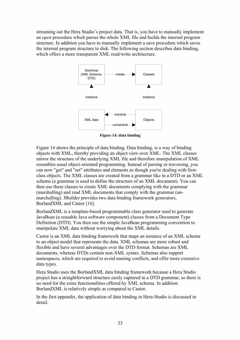
Figure 14: data binding
Figure 14 shows the principle of data binding. Data binding, is a way of binding objects with XML, thereby providing an object view over XML. The XML classes mirror the structure of the underlying XML file and therefore manipulation of XML resembles usual object-oriented programming. Instead of parsing or traversing, you can now "get" and "set" attributes and elements as though you're dealing with first-class objects. The XML classes are created from a grammar like in a DTD or an XML schema (a grammar is used to define the structure of an XML document). You can then use these classes to create XML documents complying with the grammar (marshalling) and read XML documents that comply with the grammar (un-marchalling). JBuilder provides two data binding framework generators, BorlandXML and Castor [16].
BorlandXML is a template-based programmable class generator used to generate JavaBean (a reusable Java software component) classes from a Document Type Definition (DTD). You then use the simple JavaBean programming convention to manipulate XML data without worrying about the XML details.
Castor is an XML data binding framework that maps an instance of an XML schema to an object model that represents the data. XML schemas are more robust and flexible and have several advantages over the DTD format. Schemas are XML documents, whereas DTDs contain non-XML syntax. Schemas also support namespaces, which are required to avoid naming conflicts, and offer more extensive data types.
Hera Studio uses the BorlandXML data binding framework because a Hera Studio project has a straightforward structure easily captured in a DTD grammar, so there is no need for the extra functionalities offered by XML schema. In addition BorlandXML is relatively simple as compared to Castor.
In the first appendix, the application of data binding in Hera-Studio is discussed in detail.
33
4.2 Program structure
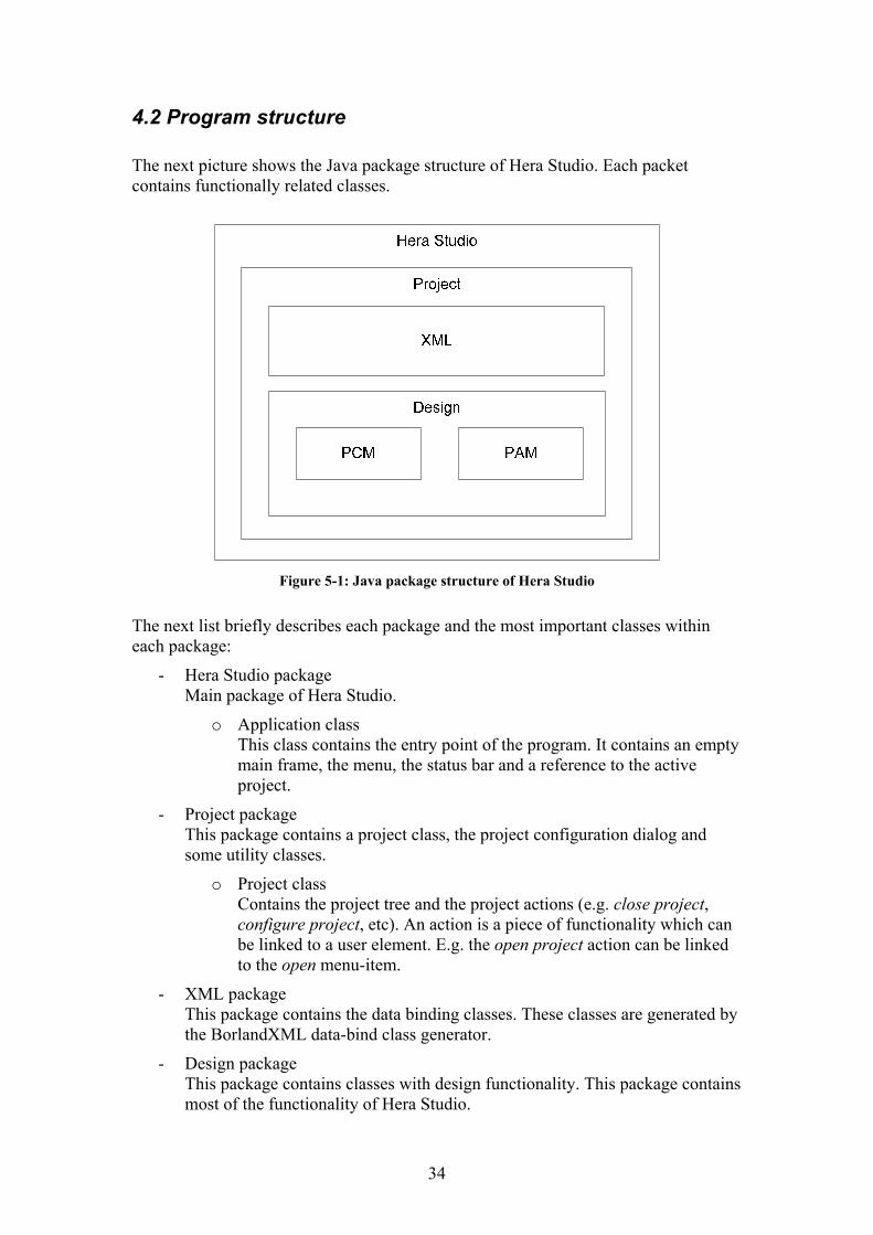
The next picture shows the Java package structure of Hera Studio. Each packet contains functionally related classes.
Figure 5-1: Java package structure of Hera Studio
The next list briefly describes each package and the most important classes within each package:
- Hera Studio package Main package of Hera Studio.
o Application class This class contains the entry point of the program. It contains an empty main frame, the menu, the status bar and a reference to the active project.
- Project package This package contains a project class, the project configuration dialog and some utility classes.
o Project class Contains the project tree and the project actions (e.g. close project, configure project, etc). An action is a piece of functionality which can be linked to a user element. E.g. the open project action can be linked to the open menu-item.
- XML package This package contains the data binding classes. These classes are generated by the BorlandXML data-bind class generator.
- Design package This package contains classes with design functionality. This package contains most of the functionality of Hera Studio.
34
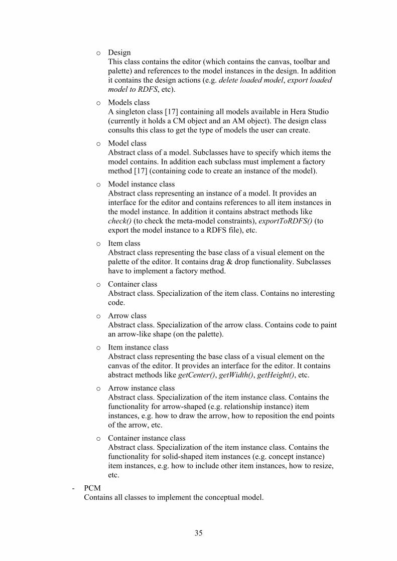
o Design This class contains the editor (which contains the canvas, toolbar and palette) and references to the model instances in the design. In addition it contains the design actions (e.g. delete loaded model, export loaded model to RDFS, etc).
o Models class A singleton class [17] containing all models available in Hera Studio (currently it holds a CM object and an AM object). The design class consults this class to get the type of models the user can create.
o Model class Abstract class of a model. Subclasses have to specify which items the model contains. In addition each subclass must implement a factory method [17] (containing code to create an instance of the model).
o Model instance class Abstract class representing an instance of a model. It provides an interface for the editor and contains references to all item instances in the model instance. In addition it contains abstract methods like check() (to check the meta-model constraints), exportToRDFS() (to export the model instance to a RDFS file), etc.
o Item class Abstract class representing the base class of a visual element on the palette of the editor. It contains drag & drop functionality. Subclasses have to implement a factory method.
o Container class Abstract class. Specialization of the item class. Contains no interesting code.
o Arrow class Abstract class. Specialization of the arrow class. Contains code to paint an arrow-like shape (on the palette).
o Item instance class Abstract class representing the base class of a visual element on the canvas of the editor. It provides an interface for the editor. It contains abstract methods like getCenter(), getWidth(), getHeight(), etc.
o Arrow instance class Abstract class. Specialization of the item instance class. Contains the functionality for arrow-shaped (e.g. relationship instance) item instances, e.g. how to draw the arrow, how to reposition the end points of the arrow, etc.
o Container instance class Abstract class. Specialization of the item instance class. Contains the functionality for solid-shaped item instances (e.g. concept instance) item instances, e.g. how to include other item instances, how to resize, etc.
- PCM Contains all classes to implement the conceptual model.
35
- PAM Contains all classes to implement the application model.
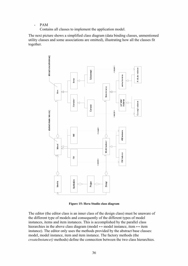
The next picture shows a simplified class diagram (data binding classes, unmentioned utility classes and some associations are omitted), illustrating how all the classes fit together.
Figure 15: Hera Studio class diagram
The editor (the editor class is an inner class of the design class) must be unaware of the different type of models and consequently of the different types of model instances, items and item instances. This is accomplished by the parallel class hierarchies in the above class diagram (model ↔ model instance, item ↔ item instance). The editor only uses the methods provided by the abstract base classes: model, model instance, item and item instance. The factory methods (the createInstance() methods) define the connection between the two class hierarchies.
36
Concrete model classes know which concrete model instance class to instantiate and concrete item classes know which concrete item instance class to instantiate. If the user drops a concrete item object onto the canvas, the editor invokes the createInstance() method of the dropped item. This method returns a concrete item instance object. The editor then uses methods of the item instance base class to interact with the concrete item instance object.
In order to support a new model, a new package within the design package has to be created. This package must contain the following classes:
- A subclass of the model class.
- A subclass of the model instance class.
- For each visual element of the model:
o A subclass of the arrow or container class.
o A subclass of the arrow instance or container instance class.
Because the super classes provide most of the functionality, extending Hera Studio to support a new model is straightforward and requires little programming effort.
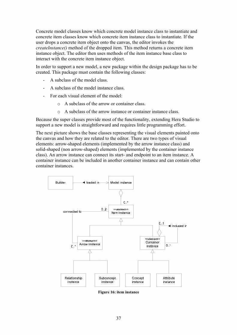
The next picture shows the base classes representing the visual elements painted onto the canvas and how they are related to the editor. There are two types of visual elements: arrow-shaped elements (implemented by the arrow instance class) and solid-shaped (non arrow-shaped) elements (implemented by the container instance class). An arrow instance can connect its start- and endpoint to an item instance. A container instance can be included in another container instance and can contain other container instances.
Figure 16: item instance
37
The editor has access to the loaded model instance and its item instances. As stated earlier, the editor only uses the methods provided by the item instance class, making it unaware of the different types of item instances. To make the editor also unaware of composite structures, i.e. item instances contained in other item instances, the composite pattern [17] is used. Basically this pattern provides transparency by moving composite related methods to the base class (item instance), making the editor unaware of which type of item instance supports composite related methods. Some implementation details to make the idea clear:
- The item instance class contains the connectToParent() method. An arrow instance cannot have a parent, so if the editor invokes this method on an arrow instance, nothing happens.
- If the editor starts dragging an item instance by means of the startDragging() method and that item instance is a container instance with children, the container instance makes sure that the children are also repositioned during the drag procedure.
38
Chapter 5: Conclusion and recommendations
Hera Studio is designed and implemented. It meets all the requirements. The conceptual- and application model are (re)defined and the way they are visually edited is refined, making it easier than before to create these models. In addition, the program is extended to support editing and exporting CMIs. Within the CM editor, the user can populate a concept and relationship with instances. When the CM is exported to RDFS, the CMI is exported to RDF. With the capability of creating HPG compatible conceptual models, conceptual model instances and application models, a presentation can be created without the need of manually editing with a text editor. Hera Studio provides a solid foundation for further development; program design is such that future models can be implemented with relatively little programming effort. The following list shows recommendations for further elaboration:
- First recommendation is to further develop Hera Studio to support all models of the Hera methodology (e.g. integration model and presentation model). Anticipating on the increasing demand for personalization, feedback and interaction, current research concentrates on the development of a new application model [18], which is more clearly structured, more flexible and has better navigational properties. Integrating this new model in Hera Studio will be the next step.
- Recent research focuses on the notion of component-based AWIS design in which an AWIS is designed using generic components. Examples of components are the Generic Adaptation Component (GAC) [19] and the Generic User Model Component (GUC) [20]. As discussed in the first chapter, the Hera methodology contains several layers, each layer transforming data from neighboring layers. Generic components could be plugged into these transformation processes, taking care of some part of the transformation process. Hera Studio could be adapted to support the usage of generic components.
- Currently, Hera Studio gets quite slow when a model grows in complexity. This is mainly caused by all the layers in the Java environment, which makes repainting visual elements slow. Hera Studio uses Swing components [21] for its visual elements. Swing uses the Abstract Window Toolkit (AWT) [22]. AWT uses platform specific APIs to render the user interface elements. It’s more efficient to use platform specific programs, e.g. implement Hera Studio in the Microsoft .NET environment [23] and exploit the 2D hardware acceleration features of the Microsoft DirectX [24] libraries. Fortunately, future Java platform releases will also support hardware acceleration (the new J2SE 5.0 already includes a new OpenGL-based pipeline for Java2D [25]). Hera Studio can take advantage of these new features by just running the program on such a new runtime environment. Reprogramming is not necessary.
- In Hera Studio, it is difficult to get an overview of very large models. Although the editor in Hera Studio can handle arbitrarily large models and even though a zoom function is present, it would be wise to further develop the Hera models to include some sort of abstraction feature. This could mean
39

that parts of a model can be grouped together and replaced by some smaller replacement item. Scalability would benefit greatly from such a feature.
- To make Hera Studio more generic, i.e. support other methodologies then Hera, the concept of a project type could be introduced. If a new project is created, the user has to choose the project type. If the user chooses Hera, for example, the CM and AM nodes become visible in the project tree. If another project type is chosen, other model types would become available.
- The final recommendation is to combine editor and engine in one program. This would result in a Hera Studio application with the HPG application integrated, making it possible to “run” the WIS from within Hera Studio instead of exporting the WIS configuration.
40
References
[1] Hera research group, Technische Universiteit Eindhoven, wwwis.win.tue.nl/~Hera/.
[2] Hera: Development of Semantic Web Information Systems by Geert-Jan Houben, Peter Barna, Flavius Frasincar, and Richard Vdovjak, Technische Universiteit Eindhoven.
[3] HPG: A Tool for Presentation Generation in WIS by Bas Rutten, Peter Barna, Flavius Frasincar, Geert-Jan Houben, and Richard Vdovjak, Technische Universiteit Eindhoven.
[4] RDF Vocabulary Description Language 1.0: RDF Schema, W3C Recommendation 10 February 2004, http://www.w3.org/TR/rdf-schema/.
[5] A Model-driven Approach for Building Distributed Ontology-based Web Applications by Richard Vdovják, thesis 2005, Technische Universiteit Eindhoven.
[6] Microsoft Office: Visio 2003, office.microsoft.com/visio
[7] The extended RMM methodology for web publishing by T. Isakowitz, A. Kamis, and M. Koufaris, Working Paper IS-98-18, Center for Research on Information Systems, 1998.
[8] Systematic hypermedia application design with OOHDM.D by Schwabe, G. Rossi, and S. D. J. Barbosa, The Tenth International World Wide Web Conference 2001, Hong Kong.
[9] Writing Application Models in HPG v2.x, Bas Rutten 2004, Technische Universiteit Eindhoven.
[10] Unified Modelling Language (UML), www.uml.org/
[11] Java Runtime Environment, www.java.com/en/download/
[12] Borland JBuilder, www.borland.com/us/products/jbuilder/
[13] Document Object Model (DOM), www.w3.org/DOM/
[14] Simple API for XML (SAX), www.saxproject.org/
[15] Streaming API for XML (StAX), jcp.org/en/jsr/detail?id=173
[16] Castor, www.castor.org/
[17] Design Patterns by Erich Gamma, Richard Helm, Ralph Johnson, John Vlissides, Addison-Wesley, 22nd Printing, July 2001
[18] Hera-S - Web Design Using Sesame by Kees van der Sluijs, Geert-Jan Houben, Jeen Broekstra and Sven Casteleyn, Technische Universiteit Eindhoven, Vrije Universiteit Brussel, Aduna, (in preparation).
[19] A Generic Transcoding Tool for Making Web Applications Adaptive by Zoltán Fiala and Geert-Jan Houben, Technische Universität Dresden, Technische Universiteit Eindhoven.
41
[20] Towards a Generic User Model Component by Kees van der Sluijs and Geert-Jan Houben, Technische Universiteit Eindhoven.
[21] Java Swing, java.sun.com/products/jfc/
[22] Abstract Window ToolKit (AWT), java.sun.com/products/jdk/awt/
[23] Microsoft .NET, www.microsoft.com/net/
[24] Microsoft DirectX, www.microsoft.com/windows/directx/
[25] Java 2 Platform Standard Edition 5.0, http://java.sun.com/j2se/1.5.0/
[26] RDF Primer, W3C Recommendation 10 February 2004, www.w3.org/TR/rdf-primer/
[27] International Movie Database (IMDB), www.imdb.com
42
Appendix: RDF
Currently HPG uses RDFS as a format for the input models. This appendix describes RDF and RDFS. Also the way Hera Studio translates the models from their visual representation in the editor to RDFS is addressed in detail by means of a simple sample CM. Part of this chapter is based on the RDF Primer [26].
5.1 RDF
The Resource Description Framework (RDF) is a family of specifications for a metadata model that is often implemented as an application of XML. The RDF family of specifications is maintained by the World Wide Web Consortium (W3C).
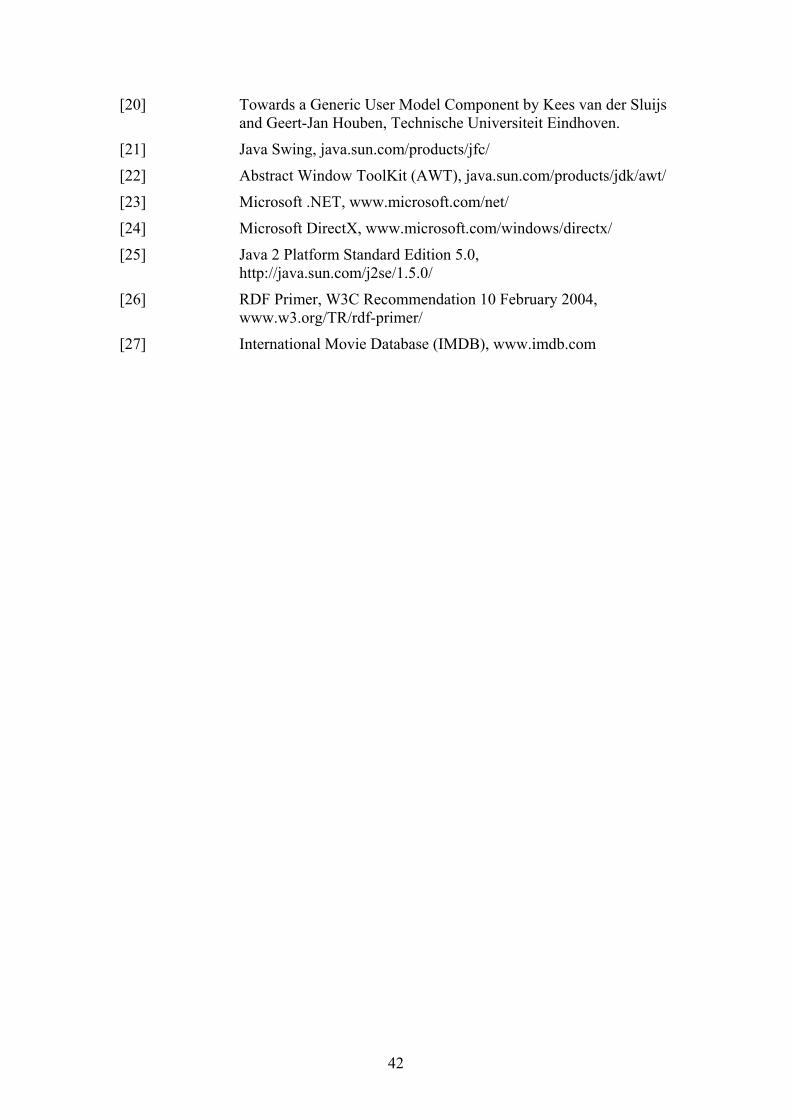
The RDF metadata model is based upon the idea of making statements about resources in the form of a subject-predicate-object expression, called a triple in RDF terminology. The subject is the resource, the “thing” being described. The predicate is a characteristic about that resource, and often expresses a relationship between the subject and the object. The object is the object of the relationship or value of that trait. A RDF graph model, see figure 17, represents a labeled directed graph and is one way of several ways to express RDF.
Figure 17: graph model of a triple
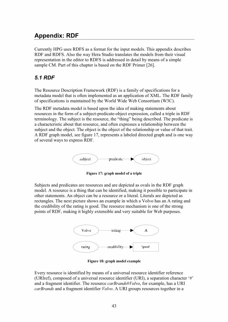
Subjects and predicates are resources and are depicted as ovals in the RDF graph model. A resource is a thing that can be identified, making it possible to participate in other statements. An object can be a resource or a literal. Literals are depicted as rectangles. The next picture shows an example in which a Volvo has an A rating and the credibility of the rating is good. The resource mechanism is one of the strong points of RDF, making it highly extensible and very suitable for Web purposes.
Figure 18: graph model example
Every resource is identified by means of a universal resource identifier reference (URIref), composed of a universal resource identifier (URI), a separation character ‘#’ and a fragment identifier. The resource carBrands#Volvo, for example, has a URI carBrands and a fragment identifier Volvo. A URI groups resources together in a
43
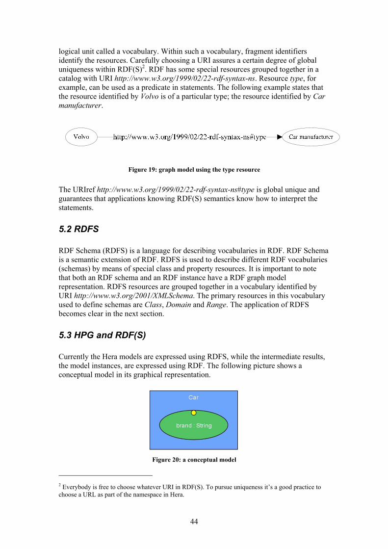
logical unit called a vocabulary. Within such a vocabulary, fragment identifiers identify the resources. Carefully choosing a URI assures a certain degree of global uniqueness within RDF(S)2. RDF has some special resources grouped together in a catalog with URI http://www.w3.org/1999/02/22-rdf-syntax-ns. Resource type, for example, can be used as a predicate in statements. The following example states that the resource identified by Volvo is of a particular type; the resource identified by Car manufacturer.
Figure 19: graph model using the type resource
The URIref http://www.w3.org/1999/02/22-rdf-syntax-ns#type is global unique and guarantees that applications knowing RDF(S) semantics know how to interpret the statements.
5.2 RDFS
RDF Schema (RDFS) is a language for describing vocabularies in RDF. RDF Schema is a semantic extension of RDF. RDFS is used to describe different RDF vocabularies (schemas) by means of special class and property resources. It is important to note that both an RDF schema and an RDF instance have a RDF graph model representation. RDFS resources are grouped together in a vocabulary identified by URI http://www.w3.org/2001/XMLSchema. The primary resources in this vocabulary used to define schemas are Class, Domain and Range. The application of RDFS becomes clear in the next section.
5.3 HPG and RDF(S)
Currently the Hera models are expressed using RDFS, while the intermediate results, the model instances, are expressed using RDF. The following picture shows a conceptual model in its graphical representation.
Figure 20: a conceptual model
2 Everybody is free to choose whatever URI in RDF(S). To pursue uniqueness it’s a good practice to choose a URL as part of the namespace in Hera.
44
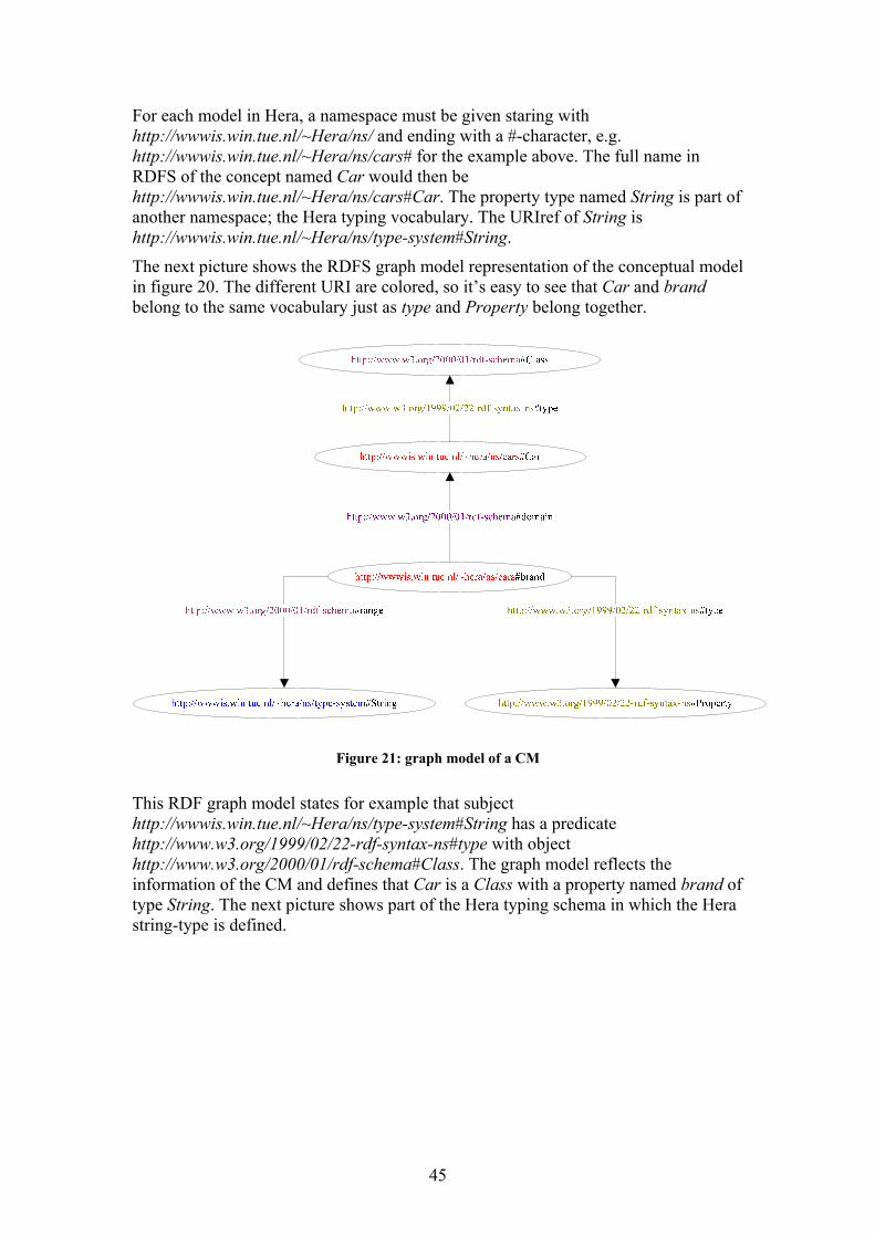
For each model in Hera, a namespace must be given staring with http://wwwis.win.tue.nl/~Hera/ns/ and ending with a #-character, e.g. http://wwwis.win.tue.nl/~Hera/ns/cars# for the example above. The full name in RDFS of the concept named Car would then be http://wwwis.win.tue.nl/~Hera/ns/cars#Car. The property type named String is part of another namespace; the Hera typing vocabulary. The URIref of String is http://wwwis.win.tue.nl/~Hera/ns/type-system#String.
The next picture shows the RDFS graph model representation of the conceptual model in figure 20. The different URI are colored, so it’s easy to see that Car and brand belong to the same vocabulary just as type and Property belong together.
Figure 21: graph model of a CM
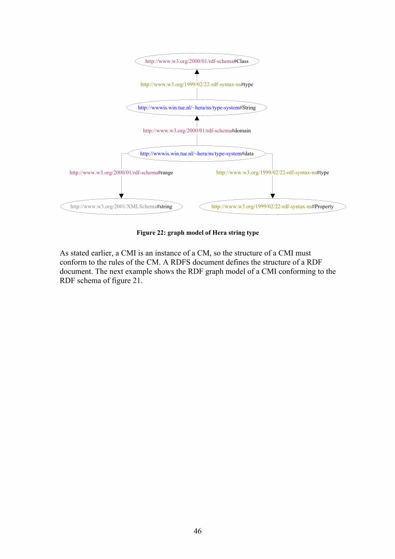
This RDF graph model states for example that subject http://wwwis.win.tue.nl/~Hera/ns/type-system#String has a predicate http://www.w3.org/1999/02/22-rdf-syntax-ns#type with object http://www.w3.org/2000/01/rdf-schema#Class. The graph model reflects the information of the CM and defines that Car is a Class with a property named brand of type String. The next picture shows part of the Hera typing schema in which the Hera string-type is defined.
45
http://www.w3.org/2000/01/rdf-schema#Class
http://www.w3.org/1999/02/22-rdf-syntax-ns#Property
http://wwwis.win.tue.nl/~hera/ns/type-system#String
http://www.w3.org/1999/02/22-rdf-syntax-ns#type
http://wwwis.win.tue.nl/~hera/ns/type-system#data
http://www.w3.org/1999/02/22-rdf-syntax-ns#type
http://www.w3.org/2000/01/rdf-schema#domain
http://www.w3.org/2001/XMLSchema#string
http://www.w3.org/2000/01/rdf-schema#range
Figure 22: graph model of Hera string type
As stated earlier, a CMI is an instance of a CM, so the structure of a CMI must conform to the rules of the CM. A RDFS document defines the structure of a RDF document. The next example shows the RDF graph model of a CMI conforming to the RDF schema of figure 21.
46
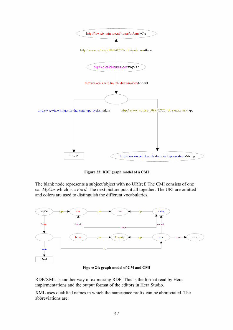
Figure 23: RDF graph model of a CMI
The blank node represents a subject/object with no URIref. The CMI consists of one car MyCar which is a Ford. The next picture puts it all together. The URI are omitted and colors are used to distinguish the different vocabularies.
Figure 24: graph model of CM and CMI
RDF/XML is another way of expressing RDF. This is the format read by Hera implementations and the output format of the editors in Hera Studio.
XML uses qualified names in which the namespace prefix can be abbreviated. The abbreviations are:
47
- rdf=”http://www.w3.org/1999/02/22-rdf-syntax-ns#” - rdfs=”http://www.w3.org/2000/01/rdf-schema#r” - type=”http://wwwis.win.tue.nl/~Hera/ns/type-system#”
The resource http://www.w3.org/1999/02/22-rdf-syntax-ns#type, for example, can be abbreviated to rdf:type. Each serialized triple consists of three XML elements. The next code fragment shows the XML serialization of the RDF graph model in figure 17: <rdf:Description rdf:about="subject"> <predicate> <rdf:Description rdf:about="object"> </rdf:Description> </predicate> </rdf:Description>
Note the additional RDF resources used in the serialization: rdf:Description and rdf:about. The next code fragment shows the XML serialization of the RDF graph model in figure 21: <rdf:Description rdf:about=”vehicleNameSpace#Car”> <rdf:type> <rdf:Description rdf:about=”http://www.w3.org/2000/01/rdf-schema#Class”> </rdf:Description> </rdf:type> </rdf:Description> <rdf:Description rdf:about=”vehicleNameSpace#brand”> <rdf:type> <rdf:Description rdf:about=”http://www.w3.org/1999/02/22-rdf-syntax-ns#Property”> </rdf:Description> </rdf:type> <rdfs:domain> <description rdf:about=”vehicleNameSpace#Car”> </description> </rdfs:domain> <rdfs:range> <description rdf:about=”http://wwwis.win.tue.nl/~Hera/ns/type-system#String”> </description> </rdfs:range> </rdf:Description>
Note that the XML namespace abbreviations cannot be used in the value of an attribute.
RDF/XML has some abbreviations:
- When a predicate arc in an RDF graph points to an object node which has no further predicate arcs, which appears in RDF/XML as an empty node element <rdf:Description rdf:about="..."> </rdf:Description> or <rdf:Description rdf:about="..." />, that form can be shortened. This is done by using the RDF URI reference of the object node as the value of an XML attribute rdf:resource on the containing property element and making the property element empty.
- Type nodes in an RDF graph, i.e. nodes with an outgoing rdf:type arc, can be expressed more concisely in RDF/XML, by replacing the rdf:Discription element width the value of the rdf:type property.
- The ‘rdf:about’ attribute containing the whole URIref can be replaced with the ‘rdf:ID’ attribute. The value of this attribute specifies the fragment identifier relative to some base address specified earlier in the XML serialization.
The next code fragment shows the XML serialization of the RDF graph model in figure 21 using the abbreviations. <cm:Car rdf:ID="myCar>
48
<cm:brand> <type:String> <type:data>Ford</type:data> </type:String> </cm:brand> </cm:Car>
The next code fragment shows the actual output, the contents of the XML file, of the CM editor in Hera Studio. <?xml version="1.0"?> <rdf:RDF xml:lang="en" xmlns:rdf="http://www.w3.org/1999/02/22-rdf-syntax-ns#" xmlns:rdfs="http://www.w3.org/2000/01/rdf-schema#" xmlns:type="http://wwwis.win.tue.nl/~Hera/ns/type-system#" xmlns:sys="http://wwwis.win.tue.nl/~Hera/ns/system#" xmlns=" http://wwwis.win.tue.nl/~Hera/ns/cars#"> <rdfs:Class rdf:ID="Car"/> <rdf:Property rdf:ID="brand"> <rdfs:domain rdf:resource="#Car"/> <rdfs:range rdf:resource="http://wwwis.win.tue.nl/~Hera/ns/type-system#String"/> </rdf:Property> </rdf:RDF>
Note that the default namespace http://wwwis.win.tue.nl/~Hera/ns/cars# is specified in the xmlns attribute of the rdf element, specifying the URI base address for RDF(S). Values of the rdf:ID attributes are preceded with the value of the xmlns attribute and a #-character, resulting in URIref http://wwwis.win.tue.nl/~Hera/ns/cars#Car and http://wwwis.win.tue.nl/~Hera/ns/cars#brand. The attribute values of rdf:resource attributes are also supplemented by the base address to get the URIref.
49
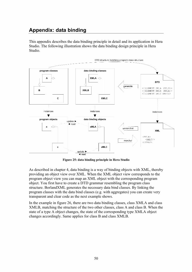
Appendix: data binding
This appendix describes the data binding principle in detail and its application in Hera Studio. The following illustration shows the data binding design principle in Hera Studio.
Figure 25: data binding principle in Hera Studio
As described in chapter 4, data binding is a way of binding objects with XML, thereby providing an object view over XML. When the XML object view corresponds to the program object view you can map an XML object with the corresponding program object. You first have to create a DTD grammar resembling the program class structure. BorlandXML generates the necessary data bind classes. By linking the program classes with the data bind classes (e.g. with aggregates) you can create very transparent and clear code as the next example shows.
In the example in figure 26, there are two data binding classes, class XMLA and class XMLB, matching the structure of the two other classes, class A and class B. When the state of a type A object changes, the state of the corresponding type XMLA object changes accordingly. Same applies for class B and class XMLB.
50
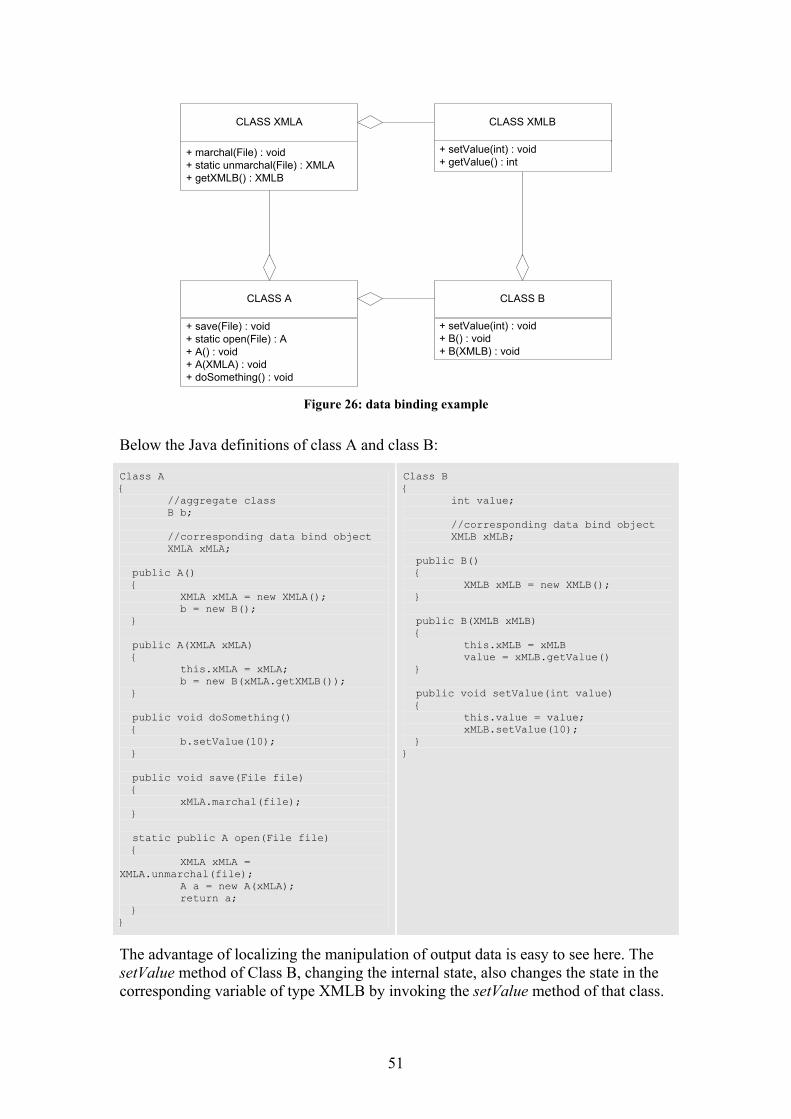
CLASS A CLASS B
+ setValue(int) : void+ B() : void+ B(XMLB) : void
CLASS XMLA
+ marchal(File) : void+ static unmarchal(File) : XMLA+ getXMLB() : XMLB
CLASS XMLB
+ save(File) : void+ static open(File) : A+ A() : void+ A(XMLA) : void+ doSomething() : void
+ setValue(int) : void+ getValue() : int
Figure 26: data binding example
Below the Java definitions of class A and class B:
Class A { //aggregate class B b; //corresponding data bind object XMLA xMLA; public A() { XMLA xMLA = new XMLA(); b = new B(); } public A(XMLA xMLA) { this.xMLA = xMLA; b = new B(xMLA.getXMLB()); } public void doSomething() { b.setValue(10); } public void save(File file) { xMLA.marchal(file); } static public A open(File file) { XMLA xMLA = XMLA.unmarchal(file); A a = new A(xMLA); return a; } }
Class B { int value; //corresponding data bind object XMLB xMLB; public B() { XMLB xMLB = new XMLB(); } public B(XMLB xMLB) { this.xMLB = xMLB value = xMLB.getValue() } public void setValue(int value) { this.value = value; xMLB.setValue(10); } }
The advantage of localizing the manipulation of output data is easy to see here. The setValue method of Class B, changing the internal state, also changes the state in the corresponding variable of type XMLB by invoking the setValue method of that class.
51
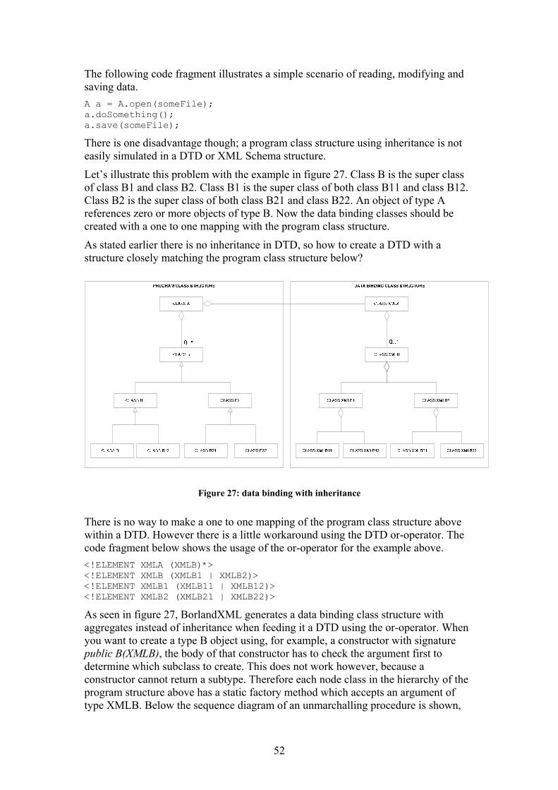
The following code fragment illustrates a simple scenario of reading, modifying and saving data. A a = A.open(someFile); a.doSomething(); a.save(someFile);
There is one disadvantage though; a program class structure using inheritance is not easily simulated in a DTD or XML Schema structure.
Let’s illustrate this problem with the example in figure 27. Class B is the super class of class B1 and class B2. Class B1 is the super class of both class B11 and class B12. Class B2 is the super class of both class B21 and class B22. An object of type A references zero or more objects of type B. Now the data binding classes should be created with a one to one mapping with the program class structure.
As stated earlier there is no inheritance in DTD, so how to create a DTD with a structure closely matching the program class structure below?
Figure 27: data binding with inheritance
There is no way to make a one to one mapping of the program class structure above within a DTD. However there is a little workaround using the DTD or-operator. The code fragment below shows the usage of the or-operator for the example above. <!ELEMENT XMLA (XMLB)*> <!ELEMENT XMLB (XMLB1 | XMLB2)> <!ELEMENT XMLB1 (XMLB11 | XMLB12)> <!ELEMENT XMLB2 (XMLB21 | XMLB22)>
As seen in figure 27, BorlandXML generates a data binding class structure with aggregates instead of inheritance when feeding it a DTD using the or-operator. When you want to create a type B object using, for example, a constructor with signature public B(XMLB), the body of that constructor has to check the argument first to determine which subclass to create. This does not work however, because a constructor cannot return a subtype. Therefore each node class in the hierarchy of the program structure above has a static factory method which accepts an argument of type XMLB. Below the sequence diagram of an unmarchalling procedure is shown,
52
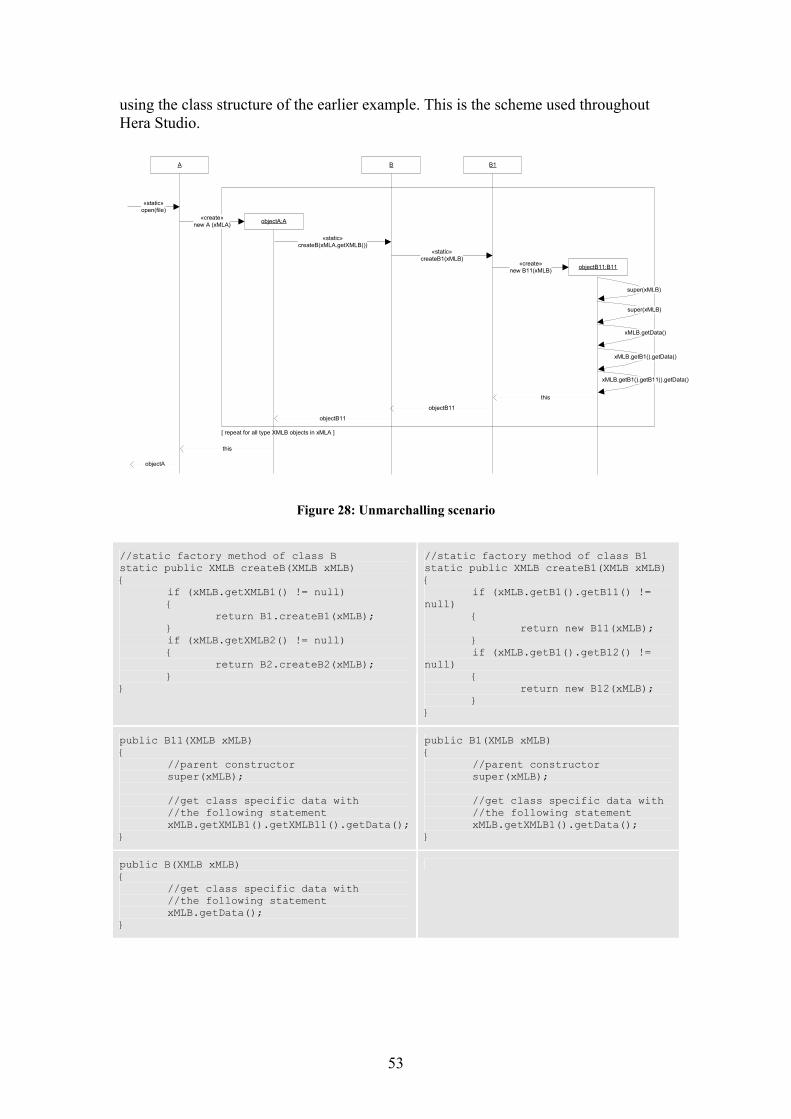
using the class structure of the earlier example. This is the scheme used throughout Hera Studio.
A B
«static»open(file)
«static»createB(xMLA.getXMLB())
B1
«static»createB1(xMLB)
objectB11:B11«create»new B11(xMLB)
this
objectB11
super(xMLB)
super(xMLB)
objectB11
[ repeat for all type XMLB objects in xMLA ]
xMLB.getData()
objectA
xMLB.getB1().getData()
xMLB.getB1().getB11().getData()
objectA:A«create»new A (xMLA)
this
Figure 28: Unmarchalling scenario
//static factory method of class B static public XMLB createB(XMLB xMLB) { if (xMLB.getXMLB1() != null) { return B1.createB1(xMLB); } if (xMLB.getXMLB2() != null) { return B2.createB2(xMLB); } }
//static factory method of class B1 static public XMLB createB1(XMLB xMLB) { if (xMLB.getB1().getB11() != null) { return new B11(xMLB); } if (xMLB.getB1().getB12() != null) { return new B12(xMLB); } }
public B11(XMLB xMLB) { //parent constructor super(xMLB); //get class specific data with //the following statement xMLB.getXMLB1().getXMLB11().getData(); }
public B1(XMLB xMLB) { //parent constructor super(xMLB); //get class specific data with //the following statement xMLB.getXMLB1().getData(); }
public B(XMLB xMLB) { //get class specific data with //the following statement xMLB.getData(); }
53
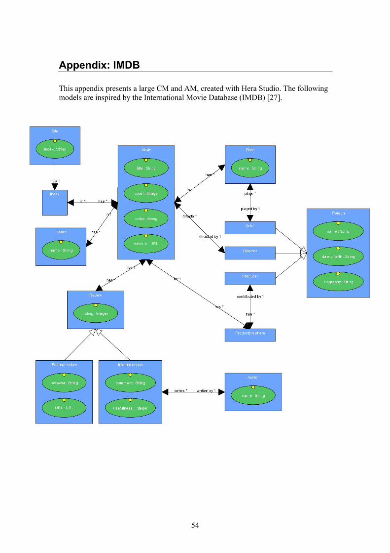
Appendix: IMDB
This appendix presents a large CM and AM, created with Hera Studio. The following models are inspired by the International Movie Database (IMDB) [27].
54
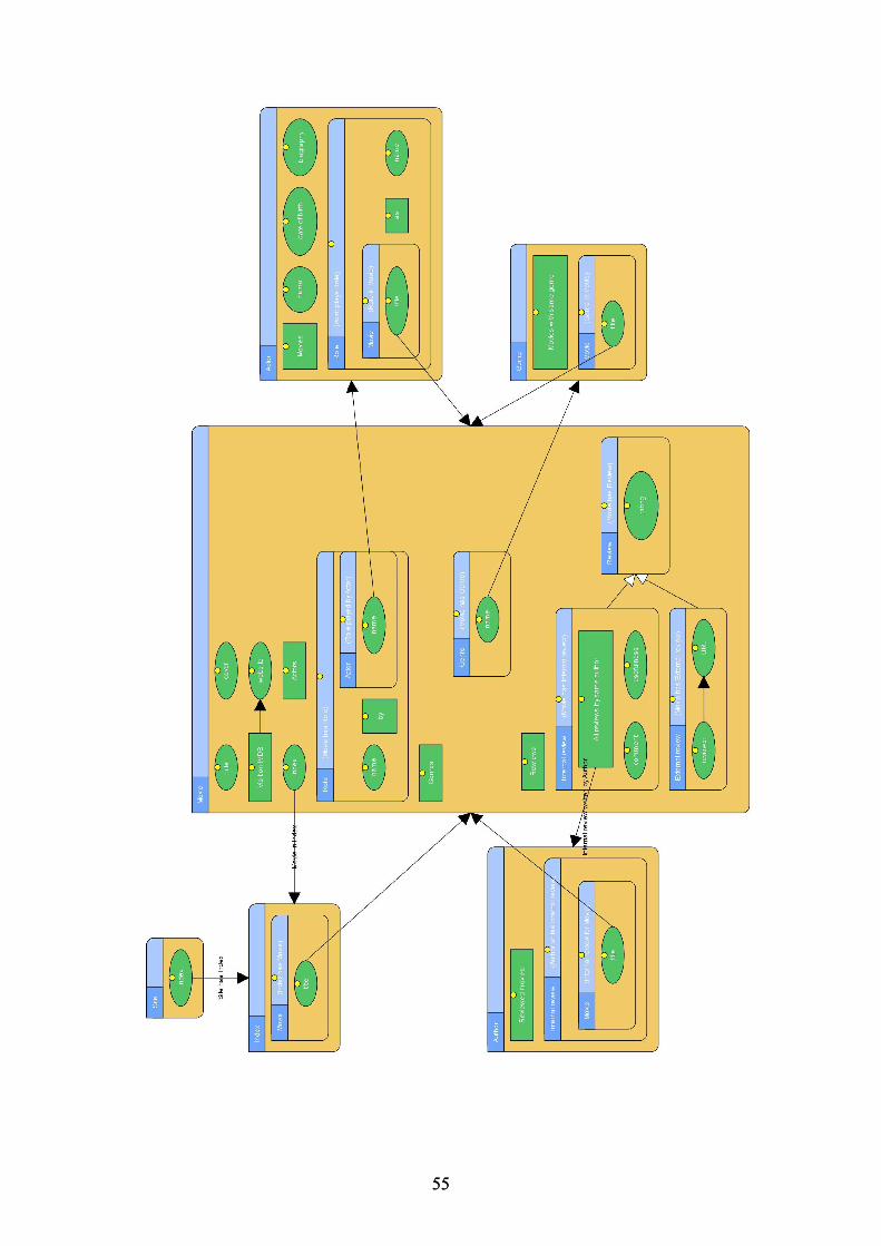
55 55