SML-D12x8, D13x8 Series: LEDs
12
SML-D12x8/D13x8 Series Data Sheet ■Features ■Outline • EXCELED TM series • Original device technology enables high brightness and high reliability ■Size ■Dimensions ■Recommended Solder Pattern ■Specifications Typ. I F Max. V R Min.* 2 Typ. Max.* 2 I F Min. Typ. I F (V) (mA) (μA) (V) (nm) (nm) (nm) (mA) (mcd) (mcd) (mA) 625 630 635 16 40 615 620 625 25 63 602 605 608 40 100 587 590 593 25 63 569 572 575 10 25 557 560 563 2.5 6.3 2.1 615 620 625 40 70 587 590 593 63 100 569 572 575 16 30 *EXCELED TM is ROHM's pending trademark. SML-D12V8W SML-D12U8W SML-D12D8W SML-D12Y8W SML-D12M8W SML-D12P8W SML-D13U8W SML-D13Y8W SML-D13M8W Emitting Color 5 PD(mW) I F (mA) Part No. Chip Structure Absolute Maximum Ratings (Ta=25ºC) Electrical and Optical Characteristics (Ta=25ºC) Power Forward Peak Forward Forward Voltage VF Reverse Current IR Dominant Wavelength λ D Luminous Intensity I V Dissipation 20 20 Orange Yellow Green Red 52 Yellow 2.2 Yellowish green 54 52 20 100* 1 5 -40〜+85 -40〜+100 2.2 20 10 EXCELED TM Yellowish green Reverse Operating Temp. Storage Temp. *1:Duty1/10, 1kHz *2:Measurement torelance:±1nm I FP (mA) V R (V) Current Current Voltage AlGaInP Red 54 T opr (ºC) T stg (ºC) Tolerance : ±0.1 (unit : mm) (unit : mm) 1608 (0603) 1.6×0.8mm (t=0.55mm) Color Type V U D Y P M 0.8 0.85 0.8 0.8 PCB Bonding Direction 1.6 1.2 0.8 0.65 0.8 0.55 0.18 Cathode index 1.5 0.5 R0.275 R0.15 Electrode ________________________________________________________ www.rohm.com ©2016 ROHM Co., Ltd. All rights reserved 1/10 2017.8 - Rev.005
Transcript of SML-D12x8, D13x8 Series: LEDs
SML-D12x8/D13x8 SeriesData Sheet
■Features ■Outline• EXCELEDTM series• Original device technology enables high brightness
and high reliability
■Size
■Dimensions ■Recommended Solder Pattern
■Specifications
Typ. IF Max. VR Min.*2 Typ. Max.*2 IF Min. Typ. IF
(V) (mA) (μA) (V) (nm) (nm) (nm) (mA) (mcd) (mcd) (mA)
625 630 635 16 40
615 620 625 25 63
602 605 608 40 100
587 590 593 25 63
569 572 575 10 25
557 560 563 2.5 6.3
2.1 615 620 625 40 70
587 590 593 63 100
569 572 575 16 30
*EXCELEDTM is ROHM's pending trademark.
SML-D12V8W
SML-D12U8W
SML-D12D8W
SML-D12Y8W
SML-D12M8W
SML-D12P8W
SML-D13U8W
SML-D13Y8W
SML-D13M8W
Emitting
Color
5
PD(mW) IF(mA)
Part No. Chip Structure
Absolute Maximum Ratings (Ta=25ºC) Electrical and Optical Characteristics (Ta=25ºC)
Power Forward Peak Forward Forward Voltage VF Reverse Current IR Dominant Wavelength λD Luminous Intensity IV
Dissipation
20 20
Orange
Yellow
Green
Red 52
Yellow2.2
Yellowish green
54
52
20 100*1 5 -40〜+85 -40〜+100
2.2
20 10
EXCELEDTM
Yellowish green
ReverseOperating Temp. Storage Temp.
*1:Duty1/10, 1kHz *2:Measurement torelance:±1nm
IFP(mA) VR(V)
Current Current Voltage
AlGaInP
Red
54
Topr(ºC) Tstg(ºC)
Tolerance : ±0.1(unit : mm) (unit : mm)
1608 (0603)
1.6×0.8mm (t=0.55mm)
ColorType V U D
Y PM
0.8
0.85
0.8
0.8
PCB Bonding Direction
1.6
1.2
0.8
0.65
0.8
0.55
0.18
Cathode index
1.5
0.5
R0.275
R0.15
Electrode
________________________________________________________ www.rohm.com ©2016 ROHM Co., Ltd. All rights reserved 1/10 2017.8 - Rev.005
[Data Sheet]
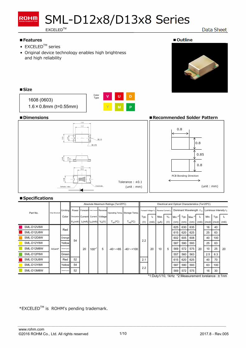
■Electrical Characteristics Curves
Fig.1 Forward Current Fig.2 Luminous Intensity - - Forward Voltages Atmosphere Temperature
Fig.3 Luminous Intensity - Forward Current Fig.4 Derating
Reference
[SML-D12x8/D13x8 series]
0.0
0.2
0.4
0.6
0.8
1.0
1.2
0 4 8 12 16 20
0.4
0.6
0.8
1
1.2
1.4
1.6
-40 -20 0 20 40 60 80 1001
10
100
1.5 2.0 2.5
Ta=25ºC
FORW
ARD
CURR
ENT
: I F
[mA]
FORWARD VOLTAGE : VF [V]
IF=20mA
RELA
TIVE
LUM
INO
US I
NTEN
SITY
[a.
u.]
ATMOSPHERE TEMPERATURE : Ta [ºC]
Ta=25ºC
RELA
TIVE
LUM
INO
US I
NTEN
SITY
FORWARD CURRENT : IF [mA]
MAX
IMUM
FO
RWAR
D CU
RREN
T :
[m
A]
AMBIENT TEMPERATURE : Ta [ºC]
SML-D12V8W SML-D12U8W SML-D12D8W SML-D12Y8W SML-D12M8W SML-D12P8W
SML-D12V8W SML-D12U8W SML-D12D8W SML-D12Y8W SML-D12M8W SML-D12P8W
SML-D12V8W SML-D12U8W SML-D12D8W SML-D12Y8W SML-D12M8W SML-D12P8W
0
10
20
30
-40 -20 0 20 40 60 80 100
SML-D12V8W SML-D12U8W SML-D12D8W SML-D12Y8W SML-D12M8W SML-D12P8W
________________________________________________________ www.rohm.com ©2016 ROHM Co., Ltd. All rights reserved 2/10 2017.8 - Rev.005
[Data Sheet]
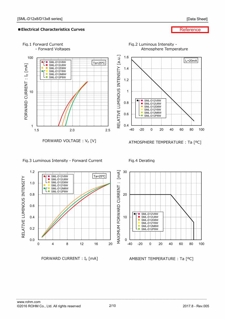
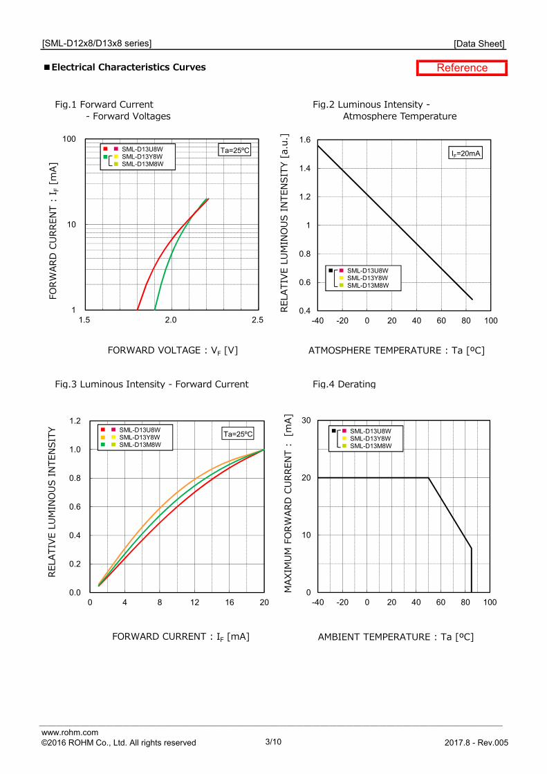
■Electrical Characteristics Curves
Fig.1 Forward Current Fig.2 Luminous Intensity - - Forward Voltages Atmosphere Temperature
Fig.3 Luminous Intensity - Forward Current Fig.4 Derating
Reference
[SML-D12x8/D13x8 series]
0.0
0.2
0.4
0.6
0.8
1.0
1.2
0 4 8 12 16 20
0.4
0.6
0.8
1
1.2
1.4
1.6
-40 -20 0 20 40 60 80 1001
10
100
1.5 2.0 2.5
Ta=25ºC IF=20mA
Ta=25ºC
FORW
ARD
CURR
ENT
: I F
[mA]
FORWARD VOLTAGE : VF [V]
RELA
TIVE
LUM
INO
US I
NTEN
SITY
[a.
u.]
ATMOSPHERE TEMPERATURE : Ta [ºC]
RELA
TIVE
LUM
INO
US I
NTEN
SITY
FORWARD CURRENT : IF [mA]
MAX
IMUM
FO
RWAR
D CU
RREN
T :
[m
A]
AMBIENT TEMPERATURE : Ta [ºC]
SML-D13U8W SML-D13Y8W SML-D13M8W
SML-D13U8W SML-D13Y8W SML-D13M8W
SML-D13U8W SML-D13Y8W SML-D13M8W
0
10
20
30
-40 -20 0 20 40 60 80 100
SML-D13U8W SML-D13Y8W SML-D13M8W
________________________________________________________ www.rohm.com ©2016 ROHM Co., Ltd. All rights reserved 3/10 2017.8 - Rev.005
[Data Sheet]
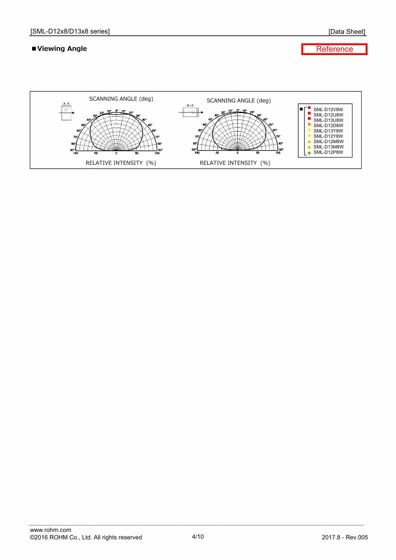
■Viewing Angle Reference
[SML-D12x8/D13x8 series]
SML-D12V8W SML-D12U8W SML-D13U8W SML-D12D8W SML-D13Y8W SML-D12Y8W SML-D12M8WSML-D13M8WSML-D12P8W
SCANNING ANGLE (deg) SCANNING ANGLE (deg)
RELATIVE INTENSITY (%) RELATIVE INTENSITY (%)
________________________________________________________ www.rohm.com ©2016 ROHM Co., Ltd. All rights reserved 4/10 2017.8 - Rev.005
[Data Sheet]
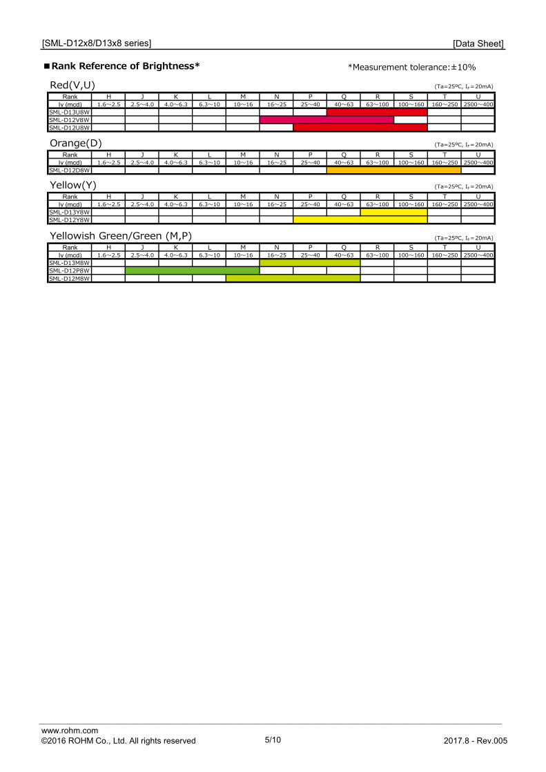
■Rank Reference of Brightness* *Measurement tolerance:±10%
[SML-D12x8/D13x8 series]
Red(V,U) (Ta=25ºC, IF=20mA)
Rank H J K L M N P Q R S T UIv (mcd) 1.6〜2.5 2.5〜4.0 4.0〜6.3 6.3〜10 10〜16 16〜25 25〜40 40〜63 63〜100 100〜160 160〜250 2500〜400
SML-D13U8WSML-D12V8WSML-D12U8W
Orange(D) (Ta=25ºC, IF=20mA)
Rank H J K L M N P Q R S T UIv (mcd) 1.6〜2.5 2.5〜4.0 4.0〜6.3 6.3〜10 10〜16 16〜25 25〜40 40〜63 63〜100 100〜160 160〜250 2500〜400
SML-D12D8W
Yellow(Y) (Ta=25ºC, IF=20mA)
Rank H J K L M N P Q R S T UIv (mcd) 1.6〜2.5 2.5〜4.0 4.0〜6.3 6.3〜10 10〜16 16〜25 25〜40 40〜63 63〜100 100〜160 160〜250 2500〜400
SML-D13Y8WSML-D12Y8W
Yellowish Green/Green (M,P) (Ta=25ºC, IF=20mA)Rank H J K L M N P Q R S T U
Iv (mcd) 1.6〜2.5 2.5〜4.0 4.0〜6.3 6.3〜10 10〜16 16〜25 25〜40 40〜63 63〜100 100〜160 160〜250 2500〜400SML-D13M8WSML-D12P8WSML-D12M8W
________________________________________________________ www.rohm.com ©2016 ROHM Co., Ltd. All rights reserved 5/10 2017.8 - Rev.005
[Data Sheet]
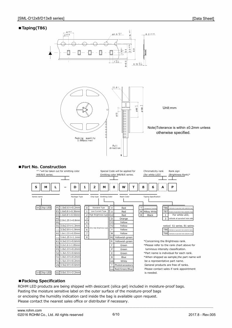
■Taping(T86)
Unit:mm
Note)Tolerance is within ±0.2mm unless
otherwise specified.
■Part No. Construction
■Packing SpecificationROHM LED products are being shipped with desiccant (silica gel) included in moisture-proof bags.
or enclosing the humidity indication card inside the bag is available upon request.Please contact the nearest sales office or distributer if necessary.
[SML-D12x8/D13x8 series]
Pasting the moisture sensitive label on the outer surface of the moisture-proof bags
8.0
1.75
3.5
5.5
0~0.51
2
1.9
φ180
φ60
φ13
±0.1
±0.05 φ1.5+0.1 ±
0.1
+1 0 -30
±0.05
0
0.73
4
Packing quantity3,000pcs/reel
Pulldirection
11.4 ±1
+0.1-0.07
+0.1-0.07
±0.1
0 .2 ±0.05
*"-"will be taken out for emitting color Special Code will be applied for Chromaticity rank Rank signWB/B/E series. Emitting color WB/B/E series. (for white LED) (Brightness Rank)*
Series name Package Type Chip type Emitting Color Resin Color Taping Specification
SML P1 0 V TE1 1 U WD1 2 U2 BH1 3 DM1 4 Y301 5 Y2 notice)S1 series、81 seiresZ1/ZN 6 YA1 7 W81/82 8 M2K1 M *Concerning the Brightness rank.S1 F *Please refer to the rank chart above for P2 P luminous intensity classification.52 E *Part name is individual for each rank.P34 B *When shipped as sample,the part name will P36 WB be a representative part name.VN T General products are free of ranks.
RGB Please contact sales if rank appointmentSCM 01 is needed.
Transparent Colorless T86 Cathode at sprocket hole side(the top)
1.6x0.8 t=0.55mmLow Current Type Red Milkey White T87
1BlackAnode at sprocket hole side(the top)
High Brightness type For white LED,Redcsthode at sprocket hole side
Red/Green/Blue
Cathode at sprocket hole side(the back)
3.0x1.5 t=2.2mm
3.5x2.8 t=0.6mm Phototransistors
Chip LED
1.0x1.0 t=0.2mm Blue1.5x1.0 t=0.2mm White
1.3x1.5 t=0.6mm Green
3.2x1.6 t=1.85mm Green1.0x1.0 t=0.2mm Green
4.5x2.0 t=0.6mm Yellowish green
1.6x1.15 t=0.55mm T68 Cathode at sprocket hole side(the top)
T86Ultra High Brightness type
3.0x2.0 t=1.3mm3.5x2.8 t=1.9mm
Yellowish green
Yellow
3.4x1.25 t=1.1mm
2.0x1.25 t=0.8mm
YellowYellowYellow
Orange 3
Chip LED 1.0x0.6 t=0.2mm1.6x0.8 t=0.36mm
Red
P
Standard Type
1S M L - D 6 A2 M 8 W T 8
________________________________________________________ www.rohm.com ©2016 ROHM Co., Ltd. All rights reserved 6/10 2017.8 - Rev.005
[Data Sheet]
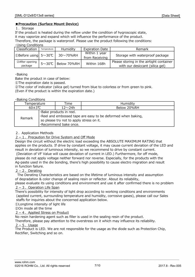
1.StorageIf the product is heated during the reflow under the condition of hygroscopic state, it may vaporize and expand which will influence the performance of the product. Therefore, the package is waterproof. Please use the product following the conditions:・Using Conditions
・BakingBake the product in case of below:①The expiration date is passed. ②The color of indicator (silica gel) turned from blue to colorless or from green to pink.
・Baking Conditions
2.Application Methods2-1.Precaution for Drive System and Off ModeDesign the circuit without the electric load exceeding the ABSOLUTE MAXIMUM RATING that
please do not apply voltage neither forward nor reverse. Especially, for the products with theAg-paste used in the die bonding, thereʼs high possibility to cause electro migration and result
2-2.Derating The Derating Characteristics are based on the lifetime of luminous intensity and assumption of degradation & color change of sealing resin or reflector. About its reliability,
2-3.Operation Life SpanThereʼs possibility for intensity of light drop according to working conditions and environments (applied current, surrounding temperature and humidity, corrosive gases), please call our Sales
①Longtime intensity of light life②On mode all the time2-4.Applied Stress on ProductNo resin hardening agent such as filler is used in the sealing resin of the product. Therefore, please pay attention to the overstress on it which may influence its reliability.2-5.UsageThe Product is LED. We are not responsible for the usage as the diode such as Protection Chip,
Classification Temperature Humidity Expiration Date Remark
①Before using 5〜30℃ 30〜70%RH Within 1 yearfrom Receiving Storage with waterproof package
②After openingpackage 5〜30℃ Below 70%RH Within 168h with our desiccant (silica gel)
(Even if the product is within the expiration date.)
60±3℃ 12〜24h Below 20%RH
[SML-D12x8/D13x8 series]
■Precaution (Surface Mount Device)
Remark so please try not to apply stress on it.・Recommend bake once.
Rectifier, Switching and so on.
Please storing in the airtight container
Temperature Time Humidity
・Bake products in reel.・Reel and embossed tape are easy to be deformed when baking,
applies on the products. If drive by constant voltage, it may cause current deviation of the LED and result in deviation of luminous intensity, so we recommend to drive by constant current. (Deviation of VF Value will cause deviation of current in LED.) Furthermore, for off mode,
in function failure.
please evaluate its using conditions and environment and use it after confirmed there is no problem.
staffs for inquiries about the concerned application below.
________________________________________________________ www.rohm.com ©2016 ROHM Co., Ltd. All rights reserved 7/10 2017.8 - Rev.005
[Data Sheet]
3.Others3-1.Surrounding GasNotice that if it is stored under the condition of acid gas (chlorine gas, sulfured gas) oralkali gas (ammonia), it may result in low soldering ability (caused by the change in quality of the plating surface ) or optical characteristics changes (light intensity, chrominance) and changein quality of cause die bonding (Ag-paste) materials. All of the above will function failure of
Therefore, please pay attention to the storage environment for mounted product (concern the
3-2.Electrostatic DamageThe product is part of semiconductor and electrostatic sensitive, thereʼs high possibility to be damaged by the electrostatic discharge. Please take appropriate measures to avoid the static electricity from human body and earthing of production equipment. The resistance values of electrostatic discharge (actual values) vary with products, therefore, please call our Sales staffs for inquiries. 3-3. Electromagnetic WaveApplications with strong electromagnetic wave such as, IH cooker, will influence the reliability of LED, therefore please evaluate before using it.
the products.
generated gas of the surrounding parts of the products and the atmospheric environment).
[SML-D12x8/D13x8 series]
________________________________________________________ www.rohm.com ©2016 ROHM Co., Ltd. All rights reserved 8/10 2017.8 - Rev.005
[Data Sheet]
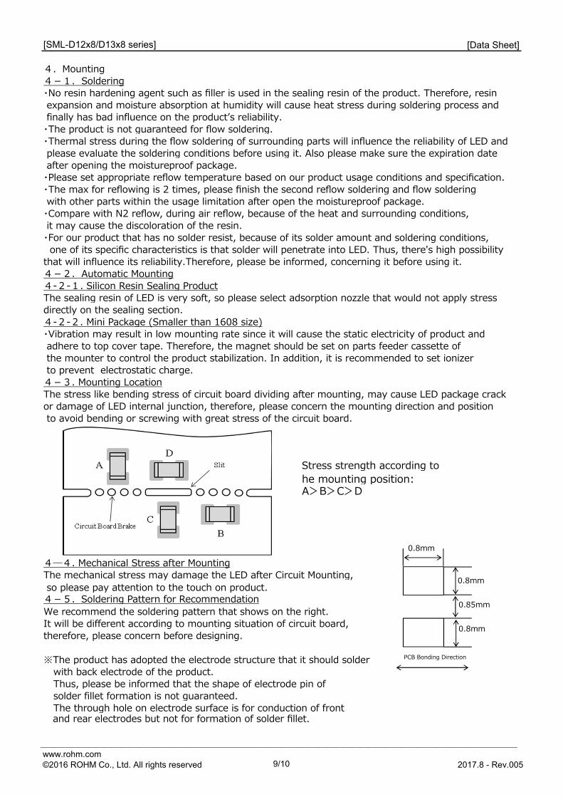
Stress strength according tohe mounting position:A>B>C>D
so please pay attention to the touch on product.
We recommend the soldering pattern that shows on the right.It will be different according to mounting situation of circuit board,therefore, please concern before designing.
※The product has adopted the electrode structure that it should solderwith back electrode of the product.Thus, please be informed that the shape of electrode pin of solder fillet formation is not guaranteed.The through hole on electrode surface is for conduction of front
and rear electrodes but not for formation of solder fillet.
4―4. Mechanical Stress after MountingThe mechanical stress may damage the LED after Circuit Mounting,
4-5.Soldering Pattern for Recommendation
to prevent electrostatic charge.4-3. Mounting LocationThe stress like bending stress of circuit board dividing after mounting, may cause LED package crack or damage of LED internal junction, therefore, please concern the mounting direction and position to avoid bending or screwing with great stress of the circuit board.
[SML-D12x8/D13x8 series]
4.Mounting4-1. Soldering・No resin hardening agent such as filler is used in the sealing resin of the product. Therefore, resin
・For our product that has no solder resist, because of its solder amount and soldering conditions, one of its specific characteristics is that solder will penetrate into LED. Thus, there's high possibilitythat will influence its reliability.Therefore, please be informed, concerning it before using it.4-2. Automatic Mounting4-2-1. Silicon Resin Sealing ProductThe sealing resin of LED is very soft, so please select adsorption nozzle that would not apply stress directly on the sealing section.4-2-2. Mini Package (Smaller than 1608 size)・Vibration may result in low mounting rate since it will cause the static electricity of product and adhere to top cover tape. Therefore, the magnet should be set on parts feeder cassette of the mounter to control the product stabilization. In addition, it is recommended to set ionizer
after opening the moistureproof package.
expansion and moisture absorption at humidity will cause heat stress during soldering process and finally has bad influence on the productʼs reliability.・The product is not guaranteed for flow soldering. ・Thermal stress during the flow soldering of surrounding parts will influence the reliability of LED and please evaluate the soldering conditions before using it. Also please make sure the expiration date
・Please set appropriate reflow temperature based on our product usage conditions and specification.・The max for reflowing is 2 times, please finish the second reflow soldering and flow soldering with other parts within the usage limitation after open the moistureproof package.・Compare with N2 reflow, during air reflow, because of the heat and surrounding conditions, it may cause the discoloration of the resin.
0.8mm
0.85mm
0.8mm
0.8mm
PCB Bonding Direction
________________________________________________________ www.rohm.com ©2016 ROHM Co., Ltd. All rights reserved 9/10 2017.8 - Rev.005
[Data Sheet]
Ultrasonic Cleaning 15W/Below 1 liter (capacity of tank)Drying Under 100℃ within 3 minutes
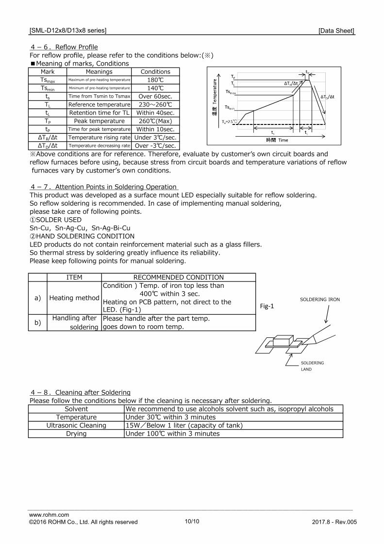
furnaces vary by customerʼs own conditions.
So thermal stress by soldering greatly influence its reliability.Please keep following points for manual soldering.
ITEM
a) Heating method
[SML-D12x8/D13x8 series]
4-6.Reflow ProfileFor reflow profile, please refer to the conditions below:(※)■Meaning of marks, Conditions
Mark Meanings ConditionsTsmax Maximum of pre-heating temperature 180℃Tsmin Minimum of pre-heating temperature 140℃
ts Time from Tsmin to Tsmax Over 60sec.TL Reference temperature 230〜260℃tL Retention time for TL Within 40sec.TP Peak temperature 260℃(Max)tP Time for peak temperature Within 10sec.
ΔTR/Δt Temperature rising rate Under 3℃/sec.ΔTD/Δt Temperature decreasing rate Over -3℃/sec.
※Above conditions are for reference. Therefore, evaluate by customerʼs own circuit boards and reflow furnaces before using, because stress from circuit boards and temperature variations of reflow
Handling after soldering
Please handle after the part temp.goes down to room temp.
4-8.Cleaning after SolderingPlease follow the conditions below if the cleaning is necessary after soldering.
Solvent We recommend to use alcohols solvent such as, isopropyl alcohols
4-7.Attention Points in Soldering Operation This product was developed as a surface mount LED especially suitable for reflow soldering.So reflow soldering is recommended. In case of implementing manual soldering,please take care of following points.①SOLDER USEDSn-Cu,Sn-Ag-Cu,Sn-Ag-Bi-Cu②HAND SOLDERING CONDITIONLED products do not contain reinforcement material such as a glass fillers.
RECOMMENDED CONDITION
Temperature Under 30℃ within 3 minutes
Heating on PCB pattern, not direct to theLED. (Fig-1)
Condition ) Temp. of iron top less than 400℃ within 3 sec.
b)
Fig‐1
SOLDERING LAND
SOLDERING IRON
________________________________________________________ www.rohm.com ©2016 ROHM Co., Ltd. All rights reserved 10/10 2017.8 - Rev.005
R1102Awww.rohm.com© 2015 ROHM Co., Ltd. All rights reserved.
Notice
ROHM Customer Support System http://www.rohm.com/contact/
Thank you for your accessing to ROHM product informations. More detail product informations and catalogs are available, please contact us.
N o t e s
The information contained herein is subject to change without notice.
Before you use our Products, please contact our sales representative and verify the latest specifica-tions :
Although ROHM is continuously working to improve product reliability and quality, semicon-ductors can break down and malfunction due to various factors.Therefore, in order to prevent personal injury or fire arising from failure, please take safety measures such as complying with the derating characteristics, implementing redundant and fire prevention designs, and utilizing backups and fail-safe procedures. ROHM shall have no responsibility for any damages arising out of the use of our Poducts beyond the rating specified by ROHM.
Examples of application circuits, circuit constants and any other information contained herein are provided only to illustrate the standard usage and operations of the Products. The peripheral conditions must be taken into account when designing circuits for mass production.
The technical information specified herein is intended only to show the typical functions of and examples of application circuits for the Products. ROHM does not grant you, explicitly or implicitly, any license to use or exercise intellectual property or other rights held by ROHM or any other parties. ROHM shall have no responsibility whatsoever for any dispute arising out of the use of such technical information.
The Products are intended for use in general electronic equipment (i.e. AV/OA devices, communi-cation, consumer systems, gaming/entertainment sets) as well as the applications indicated in this document.
The Products specified in this document are not designed to be radiation tolerant.
For use of our Products in applications requiring a high degree of reliability (as exemplified below), please contact and consult with a ROHM representative : transportation equipment (i.e. cars, ships, trains), primary communication equipment, traffic lights, fire/crime prevention, safety equipment, medical systems, servers, solar cells, and power transmission systems.
Do not use our Products in applications requiring extremely high reliability, such as aerospace equipment, nuclear power control systems, and submarine repeaters.
ROHM shall have no responsibility for any damages or injury arising from non-compliance with the recommended usage conditions and specifications contained herein.
ROHM has used reasonable care to ensur the accuracy of the information contained in this document. However, ROHM does not warrants that such information is error-free, and ROHM shall have no responsibility for any damages arising from any inaccuracy or misprint of such information.
Please use the Products in accordance with any applicable environmental laws and regulations, such as the RoHS Directive. For more details, including RoHS compatibility, please contact a ROHM sales office. ROHM shall have no responsibility for any damages or losses resulting non-compliance with any applicable laws or regulations.
When providing our Products and technologies contained in this document to other countries, you must abide by the procedures and provisions stipulated in all applicable export laws and regulations, including without limitation the US Export Administration Regulations and the Foreign Exchange and Foreign Trade Act.
This document, in part or in whole, may not be reprinted or reproduced without prior consent of ROHM.
1)
2)
3)
4)
5)
6)
7)
8)
9)
10)
11)
12)
13)
14)
093475
ノート注釈
093475 : MigrationConfirmed
093475
ノート注釈
093475 : MigrationConfirmed
Datasheet
Part Number SML-D12D8WPackage SML-D12Unit Quantity 3000Minimum Package Quantity 3000Packing Type TapingConstitution Materials List inquiryRoHS Yes
SML-D12D8W - Web PageDistribution Inventory