SIRIUS Datasheet P-1
101
s Low V oltage Controls & Distr ibution Answers for industry. SIRIUS Datasheet 2009
Transcript of SIRIUS Datasheet P-1
8/12/2019 SIRIUS Datasheet P-1
http://slidepdf.com/reader/full/sirius-datasheet-p-1 1/100
s
Low Voltage Controls & Distribution
Answers for industry.
SIRIUS
Datasheet 2009
8/12/2019 SIRIUS Datasheet P-1
http://slidepdf.com/reader/full/sirius-datasheet-p-1 2/100
8/12/2019 SIRIUS Datasheet P-1
http://slidepdf.com/reader/full/sirius-datasheet-p-1 3/1003
1 IntroductionSiemens Automation and Drives. Welcome.Sharpen your c ompetitive edge. Totally IntegratedAutomation. Integrated energy distribution from a singlesource. Totally Integrated Power.Low-Voltage Controls and Distribution - The basis forprogressive solutions.SIRIUS Industrial ControlsLow-Voltage Power Distribution
2 Controls -Contactors and Contactor Assemblies3RT Air break contactors for switching motors3RT and 3TF vacuum contactors for switching motors3RA13, 3RA14, Contactor Assemblies3RT, 3RH, 3TC, 3TK Contactors for Special Applications3RH Contactor Relays and Latched Contactor Relays
2a Controls - (Technical Information)Contactors and Contactor Assemblies3RT Air break contactors for switching motors3RT and 3TF vacuum contactors for switching motors3RA13, 3RA14, Contactor Assemblies3RT, 3RH, 3TC, 3TK Contactors for Special Applications3RH Contactor Relays and Latched Contactor Relays
3 Protection Equipment3RV Motor Protection Circuit Breaker3RB2 Microprocessor based Overload Relays3RU1 Thermal Overload Relays
3a Protection Equipment(Technical Information)3RV Motor Protection Circuit Breaker3RB2 Microprocessor based Overload Relays3RU1 Thermal Overload Relays
4Soft Starters and Motor Starters3RW Soft Starters3RE Encapsulated Starters
4a Soft Starters and Motor Starters(Technical Information)3RW Soft Starters3RE Encapsulated Starters
5 Monitoring and Control DevicesSIMOCODE 3UF Motor Management and Control Devices3UG Monitoring Relays for Electrical and Additional Measurements3RN1 Thermistor Motor Protection3TK28 Safety Relays
5a Monitoring and Control Devices(Technical Information)SIMOCODE 3UF Motor Management and Control Devices3UG Monitoring Relays for Electrical and Additional Measurements3RN1 Thermistor Motor Protection3TK28 Safety Relays
S
I R
I U S
I n
d
u
s t r i a
l
C
o
n
t r o
l s
8/12/2019 SIRIUS Datasheet P-1
http://slidepdf.com/reader/full/sirius-datasheet-p-1 4/1004
Explanations
General information
Dimensions
All dimensions in mm.
ATEX explosion protection
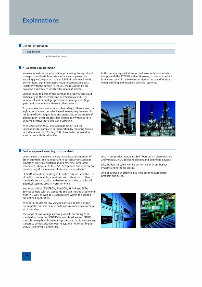
In many industries the production, processing, transport andstorage of combustible substances are accompanied byescaping gases, vapor or spray which find their way into theenvironment. Other processes result in combustible dust.Together with the oxygen in the air, the result can be anexplosive atmosphere which will explode if ignited.
Serious injury to persons and damage to property can resultparticularly in the chemical and petrochemical industry,
mineral oil and natural gas production, mining, mills (e.g.grain, solid materials) and many other sectors.
To guarantee the maximum possible safety in these areas, thelegislators of most countries have drawn up requirements inthe form of laws, regulations and standards. In the course ofglobalization, great progress has been made with regard touniform directives for explosion protection.
With Directive 94/9/EC, the European Union laid thefoundations for complete harmonization by requiring that allnew devices as from 1st July 2003 have to be approved inaccordance with this directive.
In this catalog, special attention is drawn to devices whichcomply with the ATEX Directive. However, it does not replaceintensive study of the relevant fundamentals and directiveswhen planning and installing electrical systems.
Devices approved according to UL standards
UL standards are applied in North America and a number ofother countries. This is important in particular for Europeanexports of electrical switchgear and machine-integratedequipment, above all to the USA. Acceptance and delivery arepossible only if the relevant UL standards are satisfied.
UL 508A describes the design of control cabinets and the useof builtin components, sometimes with reference to other ULstandards. As such, this standard represents the basis for allelectrical systems used in North America.
Numerous SIRIUS, SENTRON, SIVACON, ALPHA and BETAdevices comply with UL standards and can thus be used world-wide in IEC/EN as well as UL applications within the scope ofthe defined application.
With our products for low-voltage control and low-voltagecircuit protection it is easy to build control cabinets accordingto UL standard.
The range of low-voltage control products according to ULstandard includes our SENTRON circuit breakers and SIRIUScontrols - everything from motor-protective circuit breakers andstarters to contactors, overload relays, and not forgetting ourSIRIUS transformers and filters.
Also in our product range are SENTRON switch disconnectorsand various SIRIUS detecting devices and command devices.
Distribution functions can be performed with our busbarsystems and terminal blocks.
And of course our offering also includes miniature circuitbreakers and fuses.
8/12/2019 SIRIUS Datasheet P-1
http://slidepdf.com/reader/full/sirius-datasheet-p-1 5/100
Introduction
1/2 Automation and Drives. Welcome
1/4 Sharpen your competitive edge. TotalIntegrated Automation
1/6 Integrated energy distribution from asingle source. Totally Integrated Powe
1/8 Low-Voltage Controls and DistributionThe basis for progressive solutions.
1/10 SIRIUS Industrial Controls.
1/11 Low-Voltage Power Distribution.
8/12/2019 SIRIUS Datasheet P-1
http://slidepdf.com/reader/full/sirius-datasheet-p-1 6/100
1
1/2
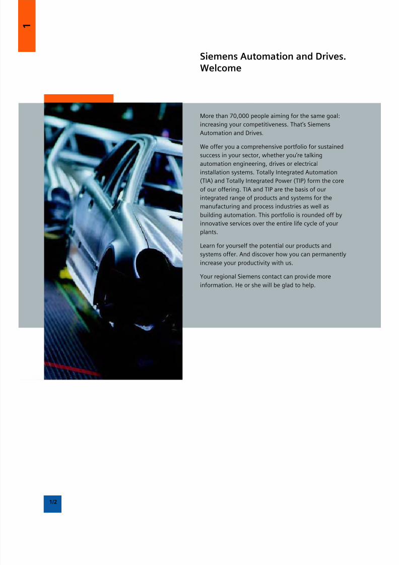
Siemens Automation and Drives.Welcome
More than 70,000 people aiming for the same goal:
increasing your competitiveness. That’s Siemens
Automation and Drives.
We offer you a comprehensive portfolio for sustained
success in your sector, whether you’re talking
automation engineering, drives or electrical
installation systems. Totally Integrated Automation
(TIA) and Totally Integrated Power (TIP) form the core
of our offering. TIA and TIP are the basis of our
integrated range of products and systems for themanufacturing and process industries as well as
building automation. This portfolio is rounded off by
innovative services over the entire life cycle of your
plants.
Learn for yourself the potential our products and
systems offer. And discover how you can permanently
increase your productivity with us.
Your regional Siemens contact can provide more
information. He or she will be glad to help.

8/12/2019 SIRIUS Datasheet P-1
http://slidepdf.com/reader/full/sirius-datasheet-p-1 7/100
8/12/2019 SIRIUS Datasheet P-1
http://slidepdf.com/reader/full/sirius-datasheet-p-1 8/100
1
1/4
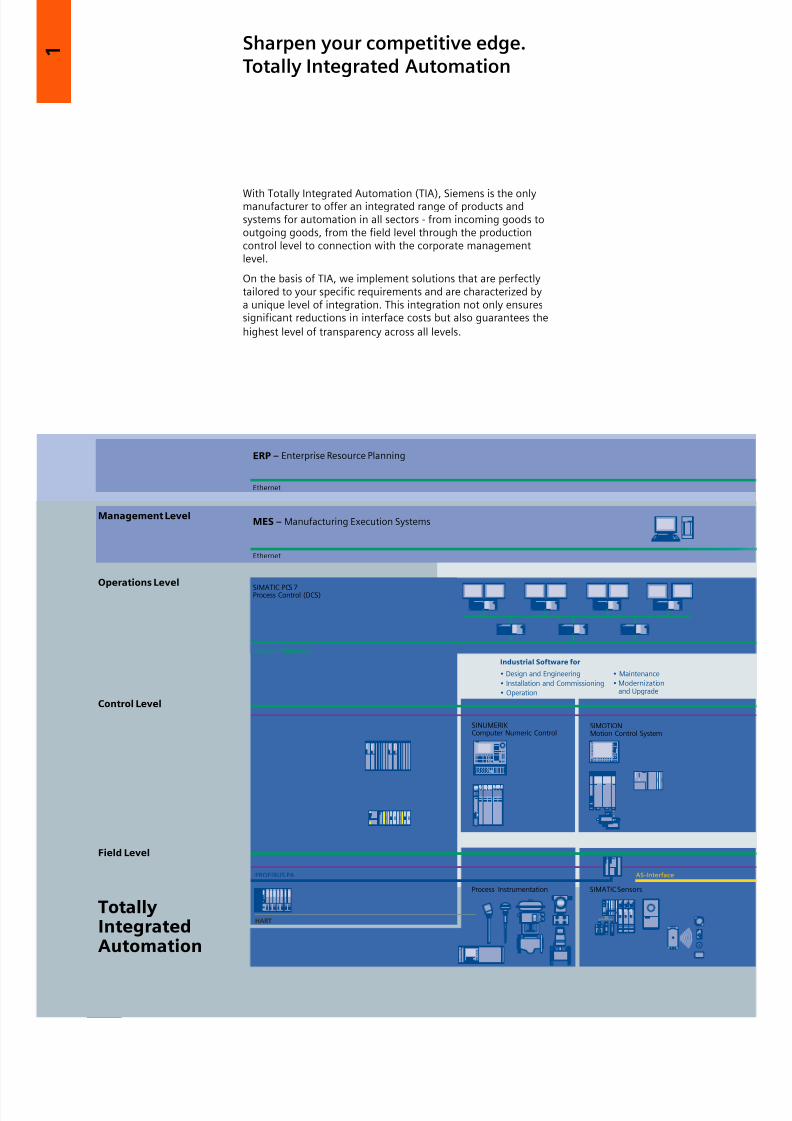
Sharpen your competitive edge.Totally Integrated Automation
With Totally Integrated Automation (TIA), Siemens is the onlymanufacturer to offer an integrated range of products andsystems for automation in all sectors - from incoming goods tooutgoing goods, from the field level through the productioncontrol level to connection with the corporate managementlevel.
On the basis of TIA, we implement solutions that are perfectlytailored to your specific requirements and are characterized bya unique level of integration. This integration not only ensuressignificant reductions in interface costs but also guarantees the
highest level of transparency across all levels.
8/12/2019 SIRIUS Datasheet P-1
http://slidepdf.com/reader/full/sirius-datasheet-p-1 9/100
8/12/2019 SIRIUS Datasheet P-1
http://slidepdf.com/reader/full/sirius-datasheet-p-1 10/100
1
1/6
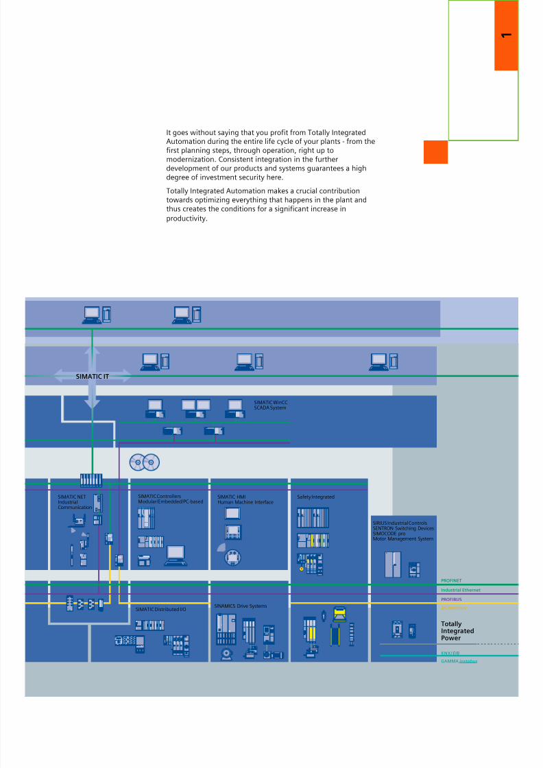
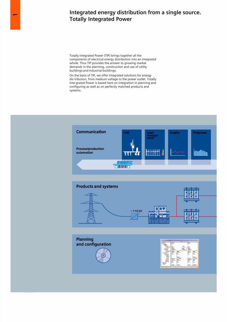
Integrated energy distribution from a single source.Totally Integrated Power
Totally Integrated Power (TIP) brings together all thecomponents of electrical energy distribution into an integratedwhole. Thus TIP provides the answer to growing marketdemands in the planning, construction and use of utilitybuildings and industrial buildings.
On the basis of TIP, we offer integrated solutions for energydis-tribution, from medium voltage to the power outlet. TotallyInte-grated Power is based here on integration in planning andconfiguring as well as on perfectly matched products andsystems.
8/12/2019 SIRIUS Datasheet P-1
http://slidepdf.com/reader/full/sirius-datasheet-p-1 11/100
1
1/7
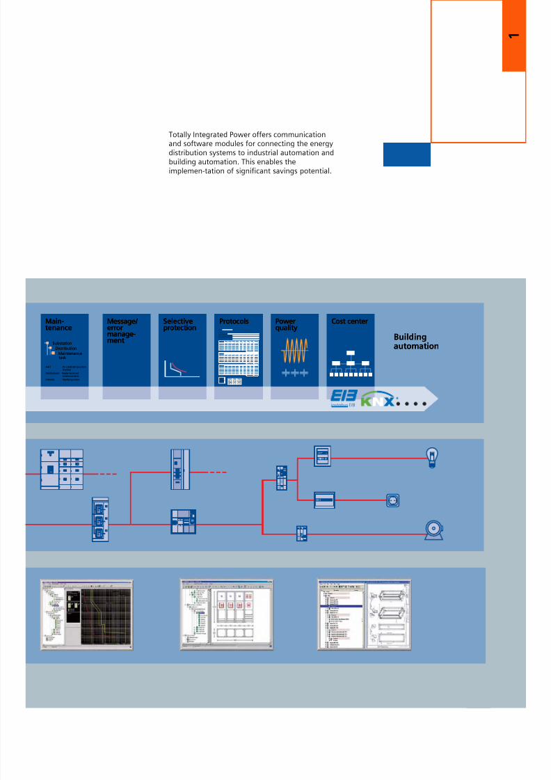
Totally Integrated Power offers communicationand software modules for connecting the energydistribution systems to industrial automation andbuilding automation. This enables theimplemen-tation of significant savings potential.
8/12/2019 SIRIUS Datasheet P-1
http://slidepdf.com/reader/full/sirius-datasheet-p-1 12/100
1
1/8
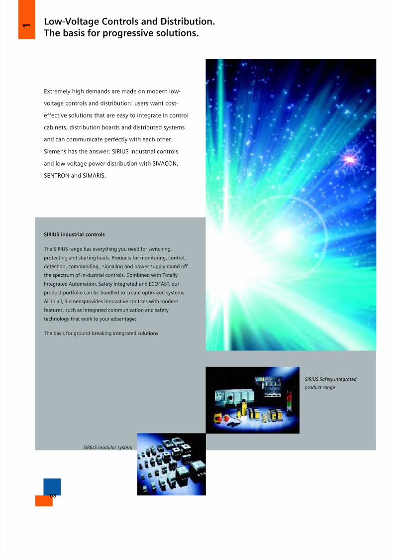
Low-Voltage Controls and Distribution.The basis for progressive solutions.
Extremely high demands are made on modern low-
voltage controls and distribution: users want cost-
effective solutions that are easy to integrate in control
cabinets, distribution boards and distributed systems
and can communicate perfectly with each other.
Siemens has the answer: SIRIUS industrial controls
and low-voltage power distribution with SIVACON,
SENTRON and SIMARIS.
SIRIUS industrial controls
The SIRIUS range has everything you need for switching,
protecting and starting loads. Products for monitoring, control,
detection, commanding, signaling and power supply round off
the spectrum of in-dustrial controls. Combined with Totally
Integrated Automation, Safety Integrated and ECOFAST, our
product portfolio can be bundled to create optimized systems.All in all, Siemensprovides innovative controls with modern
features, such as integrated communication and safety
technology that work to your advantage:
The basis for ground-breaking integrated solutions.
SIRIUS Safety Integrated
product range
SIRIUS modular system
8/12/2019 SIRIUS Datasheet P-1
http://slidepdf.com/reader/full/sirius-datasheet-p-1 13/100
1
1/9
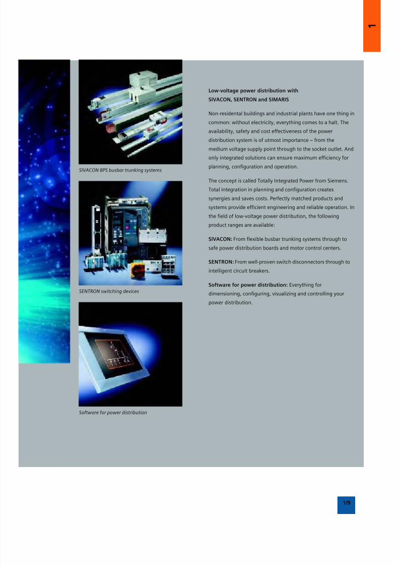
Low-voltage power distribution with
SIVACON, SENTRON and SIMARIS
Non-residental buildings and industrial plants have one thing in
common: without electricity, everything comes to a halt. The
availability, safety and cost effectiveness of the power
distribution system is of utmost importance – from the
medium voltage supply point through to the socket outlet. And
only integrated solutions can ensure maximum efficiency for
planning, configuration and operation.
The concept is called Totally Integrated Power from Siemens.
Total integration in planning and configuration creates
synergies and saves costs. Perfectly matched products and
systems provide efficient engineering and reliable operation. In
the field of low-voltage power distribution, the following
product ranges are available:
SIVACON: From flexible busbar trunking systems through to
safe power distribution boards and motor control centers.
SENTRON: From well-proven switch disconnectors through to
intelligent circuit breakers.
Software for power distribution: Everything for
dimensioning, configuring, visualizing and controlling your
power distribution.
SIVACON 8PS busbar trunking systems
SENTRON switching devices
Software for power distribution
8/12/2019 SIRIUS Datasheet P-1
http://slidepdf.com/reader/full/sirius-datasheet-p-1 14/100
1
1/10
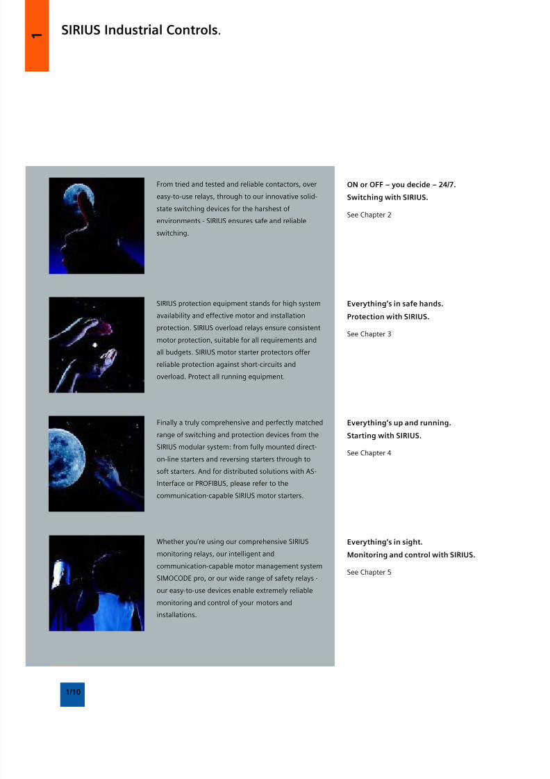
SIRIUS Industrial Controls.
From tried and tested and reliable contactors, over
easy-to-use relays, through to our innovative solid-
state switching devices for the harshest of
environments - SIRIUS ensures safe and reliable
switching.
ON or OFF – you decide – 24/7.
Switching with SIRIUS.
See Chapter 2
SIRIUS protection equipment stands for high system
availability and effective motor and installation
protection. SIRIUS overload relays ensure consistent
motor protection, suitable for all requirements and
all budgets. SIRIUS motor starter protectors offer
reliable protection against short-circuits and
overload. Protect all running equipment.
Everything’s in safe hands.
Protection with SIRIUS.
See Chapter 3
Finally a truly comprehensive and perfectly matched
range of switching and protection devices from the
SIRIUS modular system: from fully mounted direct-
on-line starters and reversing starters through to
soft starters. And for distributed solutions with AS-
Interface or PROFIBUS, please refer to the
communication-capable SIRIUS motor starters.
Everything’s up and running.
Starting with SIRIUS.
See Chapter 4
Whether you’re using our comprehensive SIRIUS
monitoring relays, our intelligent and
communication-capable motor management system
SIMOCODE pro, or our wide range of safety relays -
our easy-to-use devices enable extremely reliable
monitoring and control of your motors and
installations.
Everything’s in sight.Monitoring and control with SIRIUS.
See Chapter 5
8/12/2019 SIRIUS Datasheet P-1
http://slidepdf.com/reader/full/sirius-datasheet-p-1 15/100
1
1/11
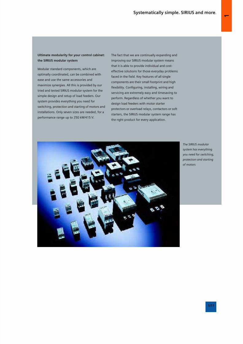
Ultimate modularity for your control cabinet:
the SIRIUS modular system
Modular standard components, which are
optimally coordinated, can be combined with
ease and use the same accessories and
maximize synergies. All this is provided by our
tried and tested SIRIUS modular system for the
simple design and setup of load feeders. Our
system provides everything you need for
switching, protection and starting of motors and
installations. Only seven sizes are needed, for a
performance range up to 250 kW/415 V.
Systematically simple. SIRIUS and more.
The fact that we are continually expanding and
improving our SIRIUS modular system means
that it is able to provide individual and cost-
effective solutions for those everyday problems
faced in the field. Key features of all single
components are their small footprint and high
flexibility. Configuring, installing, wiring and
servicing are extremely easy and timesaving to
perform. Regardless of whether you want to
design load feeders with motor starter
protectors or overload relays, contactors or soft
starters, the SIRIUS modular system range has
the right product for every application.
The SIRIUS modular
system has everything
you need for switching,
protection and starting
of motors

8/12/2019 SIRIUS Datasheet P-1
http://slidepdf.com/reader/full/sirius-datasheet-p-1 16/100
8/12/2019 SIRIUS Datasheet P-1
http://slidepdf.com/reader/full/sirius-datasheet-p-1 17/100
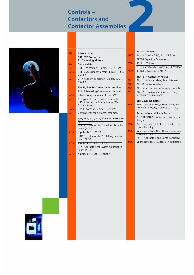
Controls –Contactors andContactor Assemblies
2/2 Introduction
3RT, 3TF Contactorsfor Switching Motors
2/4 General data
2/9 3RT10 contactors, 3-pole, 3 ... 250 kW
2/16 3RT12 vacuum contactors, 3-pole, 110 ...250 kW
2/17 3TF6 vacuum contactors, 3-pole, 335 ...450 kW
3RA13, 3RA14 Contactor Assemblies
3RA13 Reversing Contactor Assemblies
2/18 3RA13 complete units, 3 ... 45 kW2/23 Components for customer assembly
3RA14 Contactor Assemblies for Wye-Delta Starting
2/26 3RA14 complete units, 3 ...75 kW
2/33 Components for customer assembly
3RT, 3RH, 3TC, 3TH, 3TK Contactors forSpecial Applications
3RT14 Contactors for Switching ResistiveLoads (AC-1)
2/34 3-pole, 140 ... 690 A
3RT13 Contactors for Switching ResistiveLoads (AC-1)
2/35 4-pole, 4 NO, 18 ... 140 A
3TK1 Contactors for Switching ResistiveLoads (AC-1)
2/36 4-pole, 4 NO, 200 ... 1000 A
3RT15 Contactors
2/37 4-pole, 2 NO + 2 NC, 4 ... 18.5 kW
3RT16 Capacitor Contactors
2/38 12.5 ... 50 kvar
3TC Contactors for Switching DC Voltage
2/39 1- and 2-pole, 32 ... 400 A
3RH, 3TH Contactor Relays
2/41 3RH1 contactor relays, 4- and 8-pole
2/42 3RH11 contactor relays
2/43 3RH14 latched contactor relays, 4-pole
2/44 3RH11 coupling relays for switching
auxiliary circuits, 4-pole
3RT Coupling Relays
2/45 3RT10 coupling relays (interface), forswitching motors, 3-pole, 3 ... 11 kW
Accessories and Spare Parts
For 3RT, 3RH Contactors and ContactorRelays
2/46 Accessories for 3RT, 3RH contactors andcontactor relays
2/55 Spare parts for 3RT, 3RH contactors andcontactor relays
For 3T Contactors and Contactor Relays
2/56 Spare parts for 3TC, 3TF, 3TK contactors
8/12/2019 SIRIUS Datasheet P-1
http://slidepdf.com/reader/full/sirius-datasheet-p-1 18/100
2
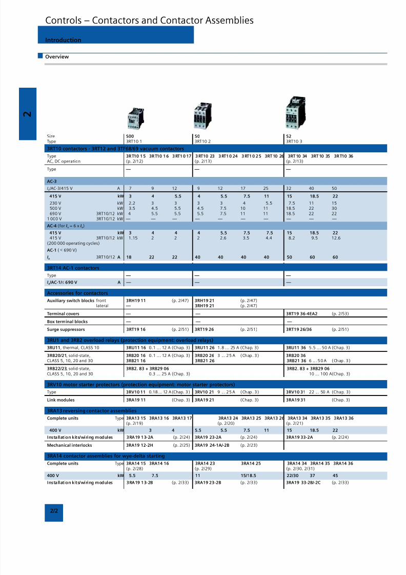
2/2
Introduction
Overview
Size S00 S0 S2Type 3RT10 1 3RT10 2 3RT10 3
3RT10 contactors · 3RT12 and 3TF68/69 vacuum contactors
Type 3RT10 15 3RT10 16 3RT10 17 3RT10 23 3RT10 24 3RT10 25 3RT10 26 3RT10 34 3RT10 35 3RT10 36AC, DC operation (p. 2/12) (p. 2/13) (p. 2/13)
Type — — —
AC-3
Ie/AC-3/415 V A 7 9 12 9 12 17 25 32 40 50
415 V kW 3 4 5.5 4 5.5 7.5 11 15 18.5 22
230 V kW 2.2 3 3 3 3 4 5.5 7.5 11 15500 V kW 3.5 4.5 5.5 4.5 7.5 10 11 18.5 22 30690 V 3RT10/12 kW 4 5.5 5.5 5.5 7.5 11 11 18.5 22 22
1 000 V 3RT10/12 kW — — — — — — — — — —
AC-4 (for Ia = 6 x Ie)
415 V kW 3 4 4 4 5.5 7.5 7.5 15 18.5 22415 V 3RT10/12 kW 1.15 2 2 2 2.6 3.5 4.4 8.2 9.5 12.6
(200 000 operating cycles)
AC-1 ( ≤ 690 V)
Ie 3RT10/12 A 18 22 22 40 40 40 40 50 60 60
3RT14 AC-1 contactors
Type — — —
Ie /AC-1/ ≤ 690 V A — — —
Accessories for contactors
Auxiliary switch blocks front 3RH19 11 (p. 2/47) 3RH19 21 (p. 2/47)lateral — 3RH19 21 (p. 2/47)
Terminal covers — — 3RT19 36-4EA2 (p. 2/53)
Box terminal blocks — — —
Surge suppressors 3RT19 16 (p. 2/51) 3RT19 26 (p. 2/51) 3RT19 26/36 (p. 2/51)
3RU1 and 3RB2 overload relays (protection equipment: overload relays)
3RU11, thermal, CLASS 10 3RU11 16 0.1 ... 12 A (Chap. 3) 3RU11 26 1.8 ... 25 A (Chap. 3) 3RU11 36 5.5 ... 50 A (Chap. 3)
3RB20/21, solid-state, 3RB20 16 0.1 ... 12 A (Chap. 3) 3RB20 26 3 .. . 25 A (Chap. 3) 3RB20 36CLASS 5, 10, 20 and 30 3RB21 16 3RB21 26 3RB21 36 6 .. . 50 A (Chap. 3)
3RB22/23, solid-state, 3RB2. 83 + 3RB29 06 3RB2. 83 + 3RB29 06CLASS 5, 10, 20 and 30 0.3 ... 25 A (Chap. 3) 10 ... 100 A(Chap. 3)
3RV10 motor starter protectors (protection equipment: motor starter protectors)
Type 3RV10 11 0.18 ... 12 A(Chap. 3 ) 3RV10 21 9 .. . 25 A (Chap. 3) 3RV10 31 22 ... 50 A (Chap. 3)
Link modules 3RA19 11 (Chap. 3) 3RA19 21 (Chap. 3) 3RA19 31 (Chap. 3)
3RA13 reversing contactor assemblies
Complete units Type 3RA13 15 3RA13 16 3RA13 17 3RA13 24 3RA13 25 3RA13 26 3RA13 34 3RA13 35 3RA13 36(p. 2/19) (p. 2/20) (p. 2/21)
400 V kW 3 4 5.5 5.5 7.5 11 15 18.5 22
Installation kits/wiring modules 3RA19 13-2A (p. 2/24) 3RA19 23-2A (p. 2/24) 3RA19 33-2A (p. 2/24)
Mechanical interlocks 3RA19 12-2H (p. 2/25) 3RA19 24-1A/-2B (p. 2/23)
3RA14 contactor assemblies for wye-delta starting
Complete units Type 3RA14 15 3RA14 16 3RA14 23 3RA14 25 3RA14 34 3RA14 35 3RA14 36(p. 2/28) (p. 2/29) (p. 2/30, 2/31)
400 V kW 5.5 7.5 11 15/18.5 22/30 37 45
Installation kits/wiring modules 3RA19 13-2B (p. 2/33) 3RA19 23-2B (p. 2/33) 3RA19 33-2B/-2C (p. 2/33)
Controls – Contactors and Contactor Assemblies
8/12/2019 SIRIUS Datasheet P-1
http://slidepdf.com/reader/full/sirius-datasheet-p-1 19/100
2
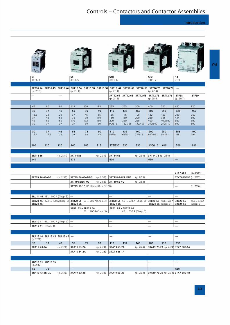
2/3
Introduction
Controls – Contactors and Contactor Assemblies
S3 S6 S10 S12 143RT1. 4 3RT1. 5 3RT1. 6 3RT1. 7 3TF6
3RT10 44 3RT10 45 3RT10 46 3RT10 54 3RT10 55 3RT10 56 3RT10 64 3RT10 65 3RT10 66 3RT10 75 3RT10 76 — (p. 2/13) (p. 2/14) (p. 2/14) (p. 2/14)
— — 3RT12 64 3RT12 65 3RT12 66 3RT12 75 3RT12 76 3TF68 3TF69(p. 2/16) (p. 2/16) (p. 2/17)
65 80 95 115 150 185 225 265 300 400 500 630 820
30 37 45 55 75 90 110 132 160 200 250 335 450
18.5 22 22 37 45 55 55 75 90 132 160 200 26037 45 55 75 90 110 160 160 200 250 355 434 60045 55 55 110 132 160 200 250 250 400 400/500 600 80030 37 37 75 90 90 90/315 132/355 132/400 250/560 250/710 600 800
30 37 45 55 75 90 110 132 160 200 250 355 40015.1 17.9 22 29 38 45 54/78 66/93 71/112 84/140 98/161 168 191
100 120 120 160 185 215 275/330 330 330 430/610 610 700 910
3RT14 46 (p. 2/34) 3RT14 56 (p. 2/34) 3RT14 66 (p. 2/34) 3RT14 76 (p. 2/34) —
140 275 400 690 —
— 3TY7 561 (p. 2/59)
3RT19 46-4EA1/2 (p. 2/53) 3RT19 56-4EA1/2/3 (p. 2/53) 3RT19 66-4EA1/2/3 (p. 2/53) 3TX7 686/696 (p. 2/57)
— 3RT19 55/56-4G (p. 2/53) 3RT19 66-4G (p. 2/53) —
3RT19 56-1C (RC element) (p. 3/108) — (p. 2/56)
3RU11 46 18 ... 100 A (Chap. 3) — — — —
3RB20 46 12.5 ... 100 A (Chap. 3) 3RB20 56 50 ... 200 A(Chap. 3) 3RB20 66 55 ... 630 A (Chap. 3) 3RB20 66 160 ... 630 A 3RB20 66 160 ... 630 A3RB21 46 3RB21 56 3RB21 66 3RB21 66 (Chap. 3) 3RB21 66 (Chap. 3)
3RB2. 83 + 3RB29 56 3RB2. 83 + 3RB29 6620 ... 200 A(Chap. 3) 63 ... 630 A (Chap. 3)
3RV10 41 45 ... 100 A (Chap. 3) — — — —
3RA19 41 (Chap. 3) — — — —
3RA13 44 3RA13 45 3RA13 46 — — — — (p. 2/22)
30 37 45 55 75 90 110 132 160 200 250 335
3RA19 43-2A (p. 2/24) 3RA19 53-2A (p. 2/24) 3RA19 63-2A (p. 2/24) 3RA19 73-2A (p. 2/24) 3TX7 680-1A
3RA19 54-2A (p. 2/23) 3TX7 686-1A
3RA14 44 3RA14 45 — — — — (p. 2/32)
55 75 — — — 630
3RA19 43-2B/-2C (p. 2/33) 3RA19 53-2B (p. 2/33) 3RA19 63-2B (p. 2/33) 3RA19 73-2B (p. 2/33) 3TX7 680-1B
8/12/2019 SIRIUS Datasheet P-1
http://slidepdf.com/reader/full/sirius-datasheet-p-1 20/100
2
2/4
Overview
General data
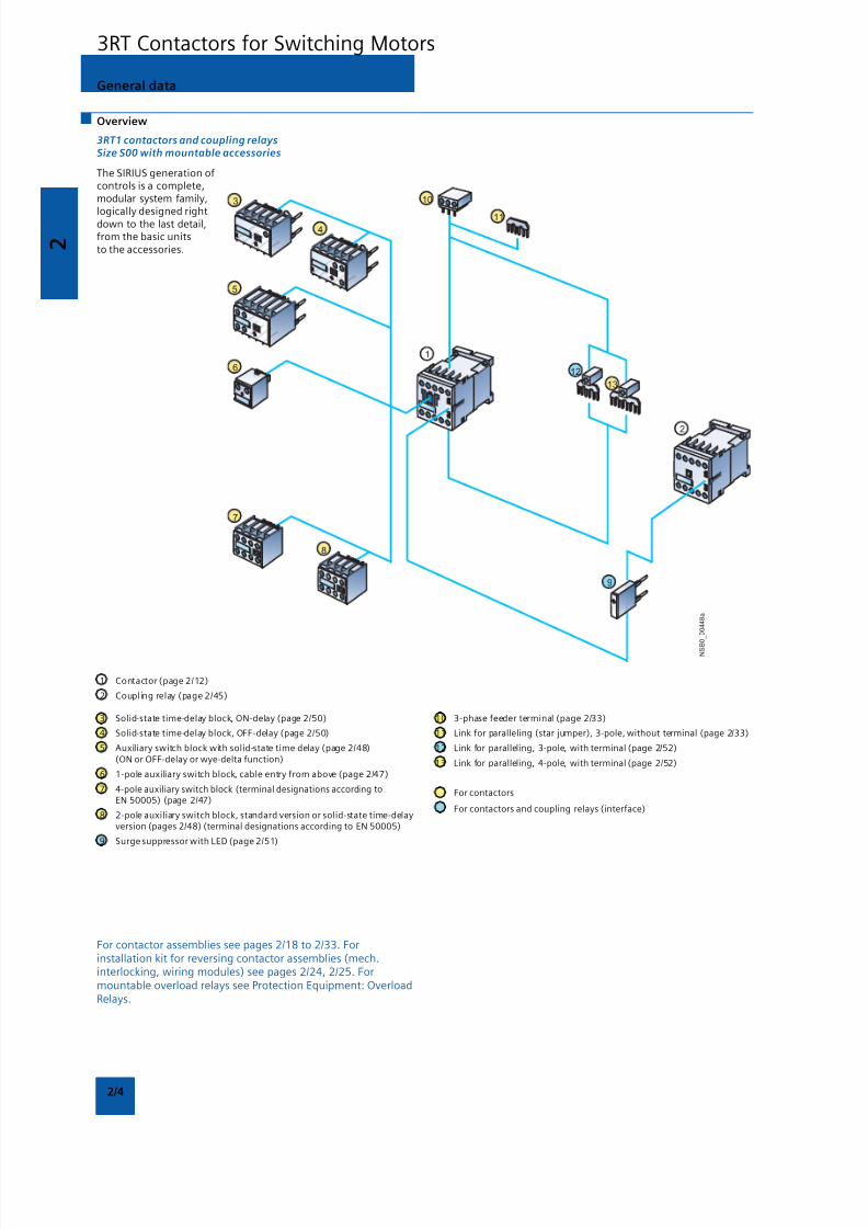
3RT1 contactors and coupling relaysSize S00 with mountable accessories
The SIRIUS generation ofcontrols is a complete,modular system family,
logically designed rightdown to the last detail,from the basic unitsto the accessories.
1 Contactor (page 2/12)
2 Coupling relay (page 2/45)
For contactor assemblies see pages 2/18 to 2/33. Forinstallation kit for reversing contactor assemblies (mech.interlocking, wiring modules) see pages 2/24, 2/25. Formountable overload relays see Protection Equipment: OverloadRelays.
3 Solid-state time-delay block, ON-delay (page 2/50)
4 Solid-state time-delay block, OFF-delay (page 2/50)
5 Auxiliary switch block with solid-state time delay (page 2/48)(ON or OFF-delay or wye-delta function)
6 1-pole auxiliary switch block, cable entry from above (page 2/47)
7 4-pole auxiliary switch block (terminal designations according toEN 50005) (page 2/47)
8 2-pole auxiliary switch block, standard version or solid-state time-delayversion (pages 2/48) (terminal designations according to EN 50005)
9 Surge suppressor with LED (page 2/51)
10 3-phase feeder terminal (page 2/33)
11 Link for paralleling (star jumper), 3-pole, without terminal (page 2/33)
12 Link for paralleling, 3-pole, with terminal (page 2/52)
13 Link for paralleling, 4-pole, with terminal (page 2/52)
For contactors
For contactors and coupling relays (interface)
3RT Contactors for Switching Motors
N S B
0_
0 0 4 4 8 a
9
3
4
5
6
7
8
13
12
1
10
11
2
8/12/2019 SIRIUS Datasheet P-1
http://slidepdf.com/reader/full/sirius-datasheet-p-1 21/100
2
2/5
N S B 0_
0 0 4 4 9 b
4
9
5
17
16
16
10
1
11
8
6
14
13
1
7
12
15
18
21
2
20
21
223
19
General data
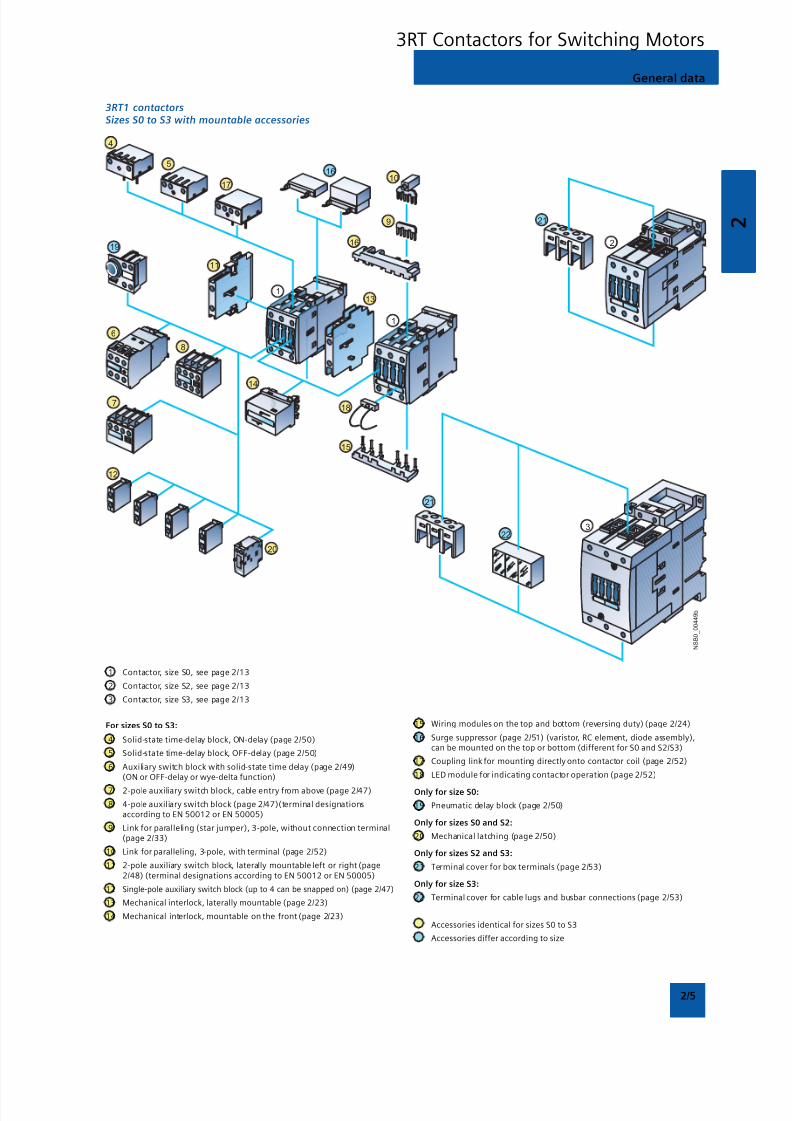
3RT1 contactorsSizes S0 to S3 with mountable accessories
1 Contactor, size S0, see page 2/13
2 Contactor, size S2, see page 2/13
3 Contactor, size S3, see page 2/13
For sizes S0 to S3:
4 Solid-state time-delay block, ON-delay (page 2/50)
5 Solid-state time-delay block, OFF-delay (page 2/50)
6 Auxiliary switch block with solid-state time delay (page 2/49)(ON or OFF-delay or wye-delta function)
7 2-pole auxiliary switch block, cable entry from above (page 2/47)
8 4-pole auxiliary switch block (page 2/47)(terminal designationsaccording to EN 50012 or EN 50005)
9 Link for paralleling (star jumper), 3-pole, without connection terminal(page 2/33)
10 Link for paralleling, 3-pole, with terminal (page 2/52)
11 2-pole auxiliary switch block, laterally mountable left or right (page2/48) (terminal designations according to EN 50012 or EN 50005)
12 Single-pole auxiliary switch block (up to 4 can be snapped on) (page 2/47)
13 Mechanical interlock, laterally mountable (page 2/23)
14 Mechanical interlock, mountable on the front (page 2/23)
15 Wiring modules on the top and bottom (reversing duty) (page 2/24)
16 Surge suppressor (page 2/51) (varistor, RC element, diode assembly),can be mounted on the top or bottom (different for S0 and S2/S3)
17 Coupling link for mounting directly onto contactor coil (page 2/52)
18 LED module for indicating contactor operation (page 2/52)
Only for size S0:
19 Pneumatic delay block (page 2/50)
Only for sizes S0 and S2:
20 Mechanical latching (page 2/50)
Only for sizes S2 and S3:
21 Terminal cover for box terminals (page 2/53)
Only for size S3:
22 Terminal cover for cable lugs and busbar connections (page 2/53)
Accessories identical for sizes S0 to S3
Accessories differ according to size
3RT Contactors for Switching Motors
8/12/2019 SIRIUS Datasheet P-1
http://slidepdf.com/reader/full/sirius-datasheet-p-1 22/100
2
2/6
N S B 0_
0 1 1 5 7 c
7
1
6
3
2
4
5
9
8
10
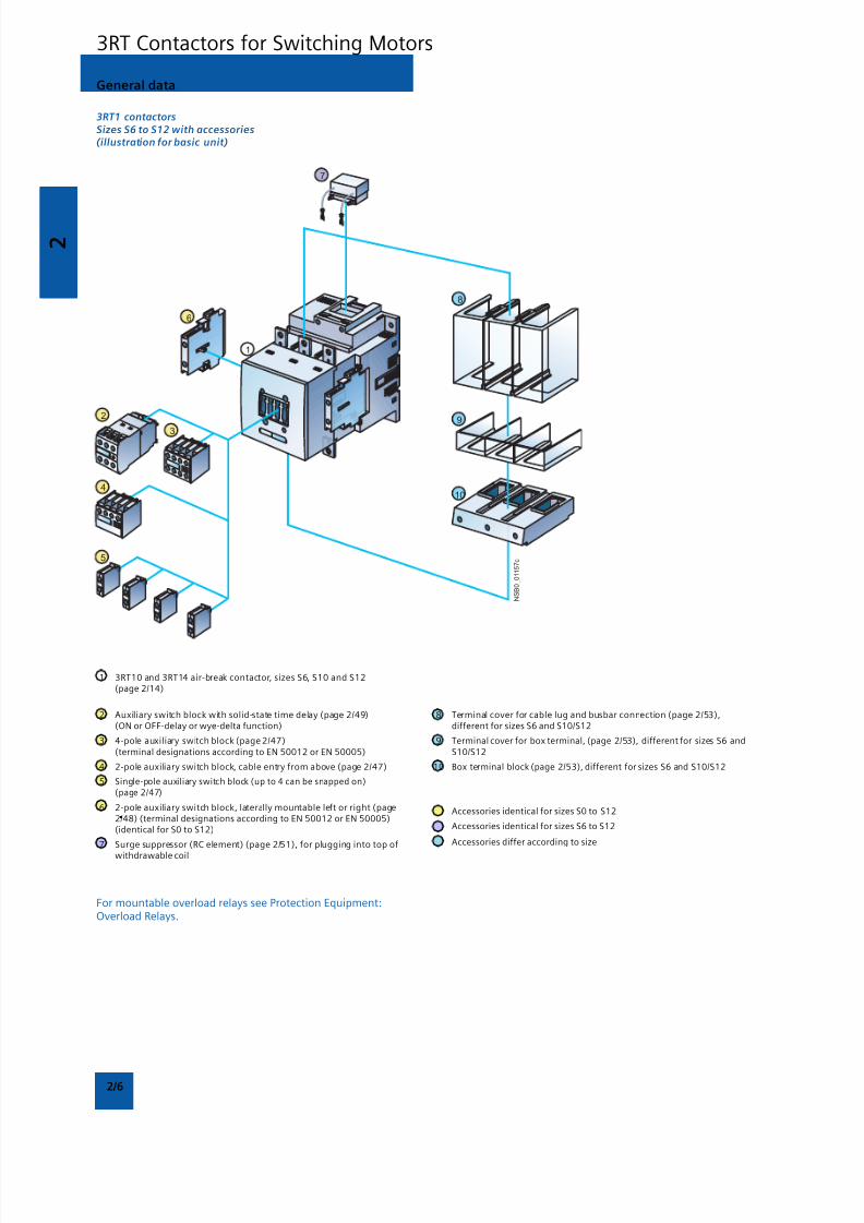
3RT1 contactorsSizes S6 to S12 with accessories(illustration for basic unit)
1 3RT10 and 3RT14 air-break contactor, sizes S6, S10 and S12(page 2/14)
2 Auxiliary switch block with solid-state time delay (page 2/49)(ON or OFF-delay or wye-delta function)
3 4-pole auxiliary switch block (page 2/47)(terminal designations according to EN 50012 or EN 50005)
4 2-pole auxiliary switch block, cable entry from above (page 2/47)
5 Single-pole auxiliary switch block (up to 4 can be snapped on)(page 2/47)
6 2-pole auxiliary switch block, laterally mountable left or right (page2/48) (terminal designations according to EN 50012 or EN 50005)(identical for S0 to S12)
7 Surge suppressor (RC element) (page 2/51), for plugging into top of
withdrawable coil
8 Terminal cover for cable lug and busbar connection (page 2/53),different for sizes S6 and S10/S12
9 Terminal cover for box terminal, (page 2/53), different for sizes S6 andS10/S12
10 Box terminal block (page 2/53), different for sizes S6 and S10/S12
Accessories identical for sizes S0 to S12
Accessories identical for sizes S6 to S12
Accessories differ according to size
For mountable overload relays see Protection Equipment:Overload Relays.
General data
3RT Contactors for Switching Motors
8/12/2019 SIRIUS Datasheet P-1
http://slidepdf.com/reader/full/sirius-datasheet-p-1 23/100

8/12/2019 SIRIUS Datasheet P-1
http://slidepdf.com/reader/full/sirius-datasheet-p-1 24/100
2
2/8
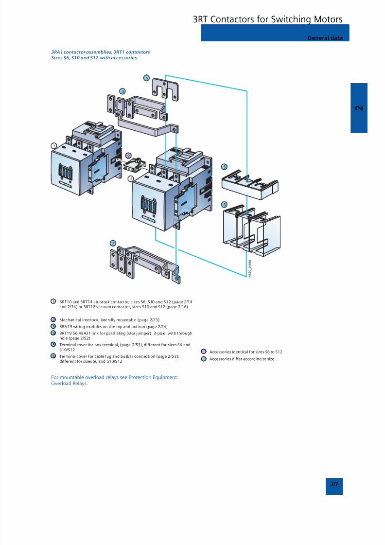
3RT1 contactors
Sizes S6 to S12 with accessories
1 Air-break contactor, sizes S6, S10 and S12 (page 2/15)
2 Vacuum contactor, sizes S10 and S12 (page 2/16)
3 Withdrawable coils for 3RT1. ..-.A.. contactors with conventionaloperating mechanism (Size S10: differentiation between 3RT10/3RT14air-break contactors and 3RT12 vacuum contactors)(Size S12: the same for air-break and vacuum contactors)
4 Withdrawable coils for 3RT1. ..-.N.. contactors with solid-stateoperating mech-anism (Size S10: differentiation between 3RT10/3RT14air-break contactors and 3RT12 vacuum contactors)(Size S12: the same for air-break and vacuum contactors)
5 Withdrawable coils and laterally mountable module (plug-on) for 3RT1...-.P.. and 3RT1. ..-.Q.. air-break contactors with solid-state operatingmechanism and remaining lifetime indicator
6 Surge suppressor (RC element) (page 2/51),plug-mountable on withdrawable coils• 3RT1...-.A.. with conventional operating mechanism• 3RT1...-.N.. with solid-state operating mechanism
Identical for sizes S6 to S12
Different according to size
For mountable overload relays see Protection Equipment:Overload Relays.
General data
3RT Contactors for Switching Motors
8/12/2019 SIRIUS Datasheet P-1
http://slidepdf.com/reader/full/sirius-datasheet-p-1 25/100
2
2/9
Overview
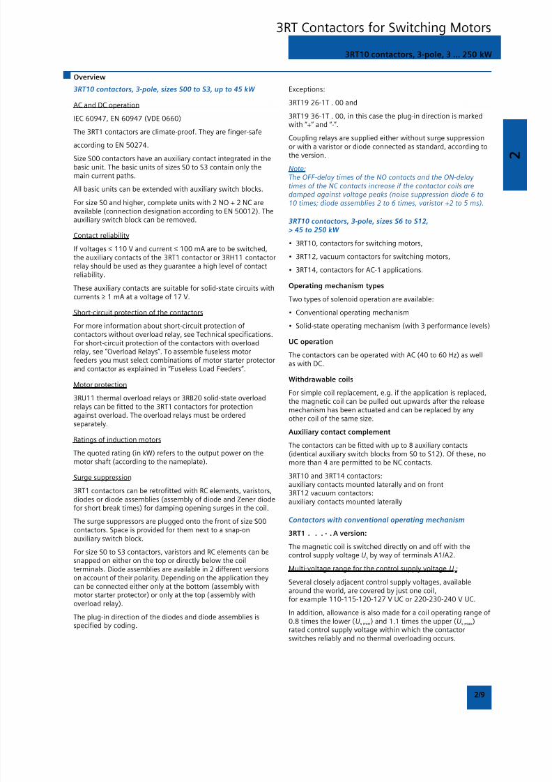
3RT10 contactors, 3-pole, sizes S00 to S3, up to 45 kW
AC and DC operation
IEC 60947, EN 60947 (VDE 0660)
The 3RT1 contactors are climate-proof. They are finger-safe
according to EN 50274.
Size S00 contactors have an auxiliary contact integrated in thebasic unit. The basic units of sizes S0 to S3 contain only themain current paths.
All basic units can be extended with auxiliary switch blocks.
For size S0 and higher, complete units with 2 NO + 2 NC areavailable (connection designation according to EN 50012). Theauxiliary switch block can be removed.
Contact reliability
If voltages ≤ 110 V and current ≤ 100 mA are to be switched,the auxiliary contacts of the 3RT1 contactor or 3RH11 contactorrelay should be used as they guarantee a high level of contact
reliability.
These auxiliary contacts are suitable for solid-state circuits withcurrents ≥ 1 mA at a voltage of 17 V.
Short-circuit protection of the contactors
For more information about short-circuit protection ofcontactors without overload relay, see Technical specifications.For short-circuit protection of the contactors with overloadrelay, see “Overload Relays”. To assemble fuseless motorfeeders you must select combinations of motor starter protectorand contactor as explained in “Fuseless Load Feeders”.
Motor protection
3RU11 thermal overload relays or 3RB20 solid-state overloadrelays can be fitted to the 3RT1 contactors for protectionagainst overload. The overload relays must be orderedseparately.
Ratings of induction motors
The quoted rating (in kW) refers to the output power on themotor shaft (according to the nameplate).
Surge suppression
3RT1 contactors can be retrofitted with RC elements, varistors,diodes or diode assemblies (assembly of diode and Zener diodefor short break times) for damping opening surges in the coil.
The surge suppressors are plugged onto the front of size S00contactors. Space is provided for them next to a snap-onauxiliary switch block.
For size S0 to S3 contactors, varistors and RC elements can besnapped on either on the top or directly below the coilterminals. Diode assemblies are available in 2 different versionson account of their polarity. Depending on the application theycan be connected either only at the bottom (assembly withmotor starter protector) or only at the top (assembly withoverload relay).
The plug-in direction of the diodes and diode assemblies isspecified by coding.
3RT10 contactors, 3-pole, 3 ... 250 kW
Exceptions:
3RT19 26-1T . 00 and
3RT19 36-1T . 00, in this case the plug-in direction is markedwith “+” and “-”.
Coupling relays are supplied either without surge suppressionor with a varistor or diode connected as standard, according tothe version.
Note:The OFF-delay times of the NO contacts and the ON-delay times of the NC contacts increase if the contactor coils aredamped against voltage peaks (noise suppression diode 6 to10 times; diode assemblies 2 to 6 times, varistor +2 to 5 ms).
3RT10 contactors, 3-pole, sizes S6 to S12,> 45 to 250 kW
• 3RT10, contactors for switching motors,
• 3RT12, vacuum contactors for switching motors,
• 3RT14, contactors for AC-1 applications.
Operating mechanism types
Two types of solenoid operation are available:
• Conventional operating mechanism
• Solid-state operating mechanism (with 3 performance levels)
UC operation
The contactors can be operated with AC (40 to 60 Hz) as wellas with DC.
Withdrawable coils
For simple coil replacement, e.g. if the application is replaced,the magnetic coil can be pulled out upwards after the release
mechanism has been actuated and can be replaced by anyother coil of the same size.
Auxiliary contact complement
The contactors can be fitted with up to 8 auxiliary contacts(identical auxiliary switch blocks from S0 to S12). Of these, nomore than 4 are permitted to be NC contacts.
3RT10 and 3RT14 contactors:auxiliary contacts mounted laterally and on front3RT12 vacuum contactors:auxiliary contacts mounted laterally
Contactors with conventional operating mechanism
3RT1 . . . - . A version:
The magnetic coil is switched directly on and off with thecontrol supply voltage Us by way of terminals A1/A2.
Multi-voltage range for the control supply voltage Us:
Several closely adjacent control supply voltages, availablearound the world, are covered by just one coil,for example 110-115-120-127 V UC or 220-230-240 V UC.
In addition, allowance is also made for a coil operating range of0.8 times the lower (Us min) and 1.1 times the upper (Us max)rated control supply voltage within which the contactorswitches reliably and no thermal overloading occurs.
3RT Contactors for Switching Motors
8/12/2019 SIRIUS Datasheet P-1
http://slidepdf.com/reader/full/sirius-datasheet-p-1 26/100
2
2/10
3RT10 contactors, 3-pole, 3 ... 250 kW
Contactors with solid-state operating mechanism
The magnetic coil is supplied selectively with the powerrequired for reliable switching and holding by upstream controlelectronics.
• Wide voltage range for the control supply voltage Us:Compared with the conventional operating mechanism, the
solid-state operating mechanism covers an even broaderrange of control supply voltages used worldwide within onecoil variant.
For example, the coil for 200 to 277 V UC (U s m in to Us ma x)covers the voltages 200-208-220-230-240-254-277 V usedworldwide.
• Extended operating range 0.7 to 1.25 x Us:The wide range for the rated control supply voltage and theadditionally allowed coil operating range of 0.8 x Us min to1.1 x Us max results in an extended coil operating range of atleast 0.7 to 1.25 x Us, within which the contactors willoperate reliably, for the most common control supplyvoltages of 24, 110 and 230 V.
• Bridging temporary voltage dips:
Control voltage failures dipping to 0 V (at A1/A2) are bridgedfor up to approx. 25 ms to avoid unintentional tripping.
• Defined ON and OFF thresholds:For voltages of ≥ 0.8 x Us min and higher the electronics willreliably switch the contactor ON, and as of ≤ 0.5 x Us min it isreliably switched OFF. The hysteresis in the switchingthresholds prevents the main contacts from chattering as wellas increased wear or welding when operated in weak,unstable networks. This also prevents thermal overloading ofthe contactor coil if the voltage applied is too low (contactordoes not close properly and is continuously operated withoverexcitation).
• Low control power consumption when closing and in theclosed state.
Electromagnetic compatibility (EMC)The contactors with solid-state operating mechanism complywith the requirements for operation in industrial plants.
• Interference immunity- burst (IEC 61000-4-4): 4 kV- surge (IEC 61000-4-5): 4 kV- electrostatic discharge, ESD (IEC 61000-4-2): 8/15 kV- electromagnetic field (IEC 61000-4-3): 10 V/m
• Emitted interference- limit value class A according to EN 55011
Note:In connection with converters, the control cables should beinstalled separately from the load cables of the converter.
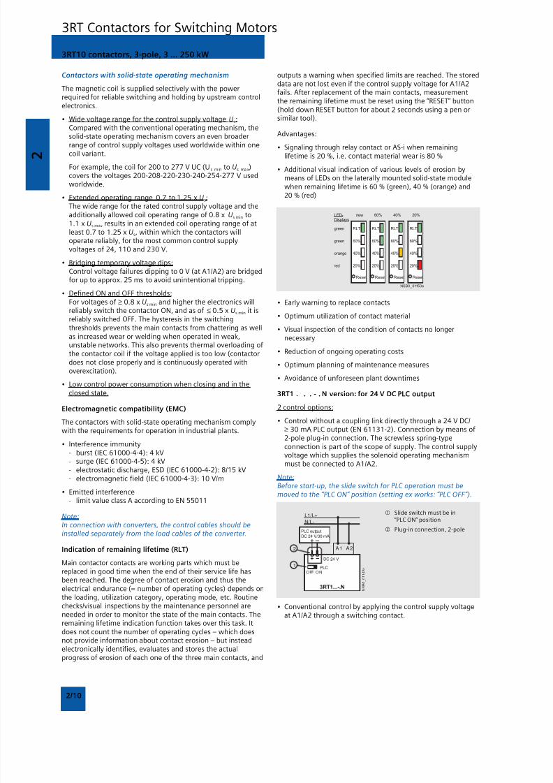
Indication of remaining lifetime (RLT)
Main contactor contacts are working parts which must bereplaced in good time when the end of their service life hasbeen reached. The degree of contact erosion and thus theelectrical endurance (= number of operating cycles) depends onthe loading, utilization category, operating mode, etc. Routinechecks/visual inspections by the maintenance personnel areneeded in order to monitor the state of the main contacts. Theremaining lifetime indication function takes over this task. Itdoes not count the number of operating cycles – which doesnot provide information about contact erosion – but insteadelectronically identifies, evaluates and stores the actualprogress of erosion of each one of the three main contacts, and
outputs a warning when specified limits are reached. The storeddata are not lost even if the control supply voltage for A1/A2fails. After replacement of the main contacts, measurementthe remaining lifetime must be reset using the “RESET” button(hold down RESET button for about 2 seconds using a pen orsimilar tool).
Advantages:• Signaling through relay contact or AS-i when remaining
lifetime is 20 %, i.e. contact material wear is 80 %
• Additional visual indication of various levels of erosion bymeans of LEDs on the laterally mounted solid-state modulewhen remaining lifetime is 60 % (green), 40 % (orange) and20 % (red)
• Early warning to replace contacts
• Optimum utilization of contact material
• Visual inspection of the condition of contacts no longernecessary
• Reduction of ongoing operating costs
• Optimum planning of maintenance measures
• Avoidance of unforeseen plant downtimes
3RT1 . . . - . N version: for 24 V DC PLC output
2 control options:
• Control without a coupling link directly through a 24 V DC/≥ 30 mA PLC output (EN 61131-2). Connection by means of2-pole plug-in connection. The screwless spring-typeconnection is part of the scope of supply. The control supplyvoltage which supplies the solenoid operating mechanismmust be connected to A1/A2.
Note:Before start-up, the slide switch for PLC operation must bemoved to the “PLC ON” position (setting ex works: “PLC OFF”).
DC 24 V
L1/L+
N/L-
A1 A2
PLCOFF ON
1
2
N S B 0_
0 1 1 4 3 c
PLC outputDC 24 V/30 mA
Slide switch must be in“PLC ON” position
Plug-in connection, 2-pole
• Conventional control by applying the control supply voltageat A1/A2 through a switching contact.
3RT Contactors for Switching Motors
8/12/2019 SIRIUS Datasheet P-1
http://slidepdf.com/reader/full/sirius-datasheet-p-1 27/100
2
2/11
Note:The slide switch must be in the “PLC OFF” position(= setting ex works)
Slide switch must be in“PLC OFF” position
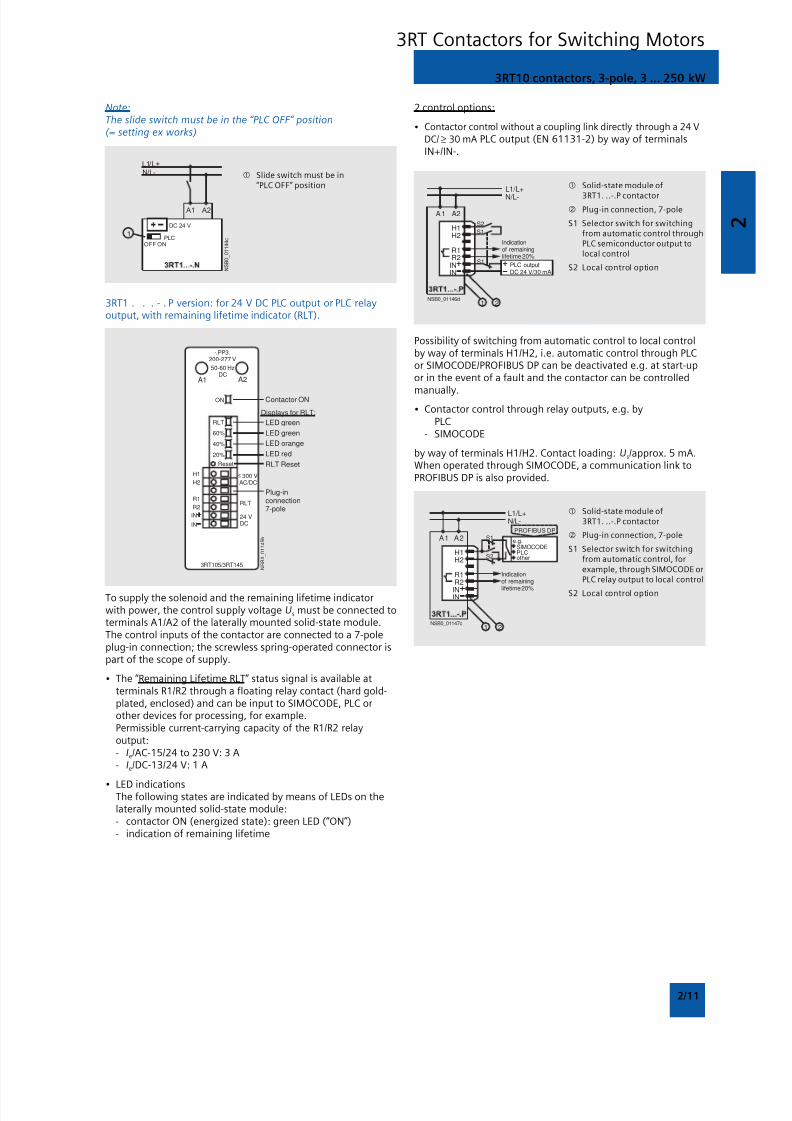
3RT1 . . . - . P version: for 24 V DC PLC output or PLC relayoutput, with remaining lifetime indicator (RLT).
ON
H1
H2
R1
R2
IN
IN
24 VDC
RLT
300 VAC/DC
A1 A2
-.PP3.200-277 V
50-60 HzDC
RLT
60%
40%
20%
Reset
3RT105/3RT145 N S B 0_
0 1 1 4 5 b
Contactor ON
Displays for RLT:
LED green
LED green
LED orange
LED red
RLT Reset
Plug-inconnection7-pole
To supply the solenoid and the remaining lifetime indicatorwith power, the control supply voltage Us must be connected toterminals A1/A2 of the laterally mounted solid-state module.The control inputs of the contactor are connected to a 7-poleplug-in connection; the screwless spring-operated connector ispart of the scope of supply.
• The “Remaining Lifetime RLT” status signal is available atterminals R1/R2 through a floating relay contact (hard gold-plated, enclosed) and can be input to SIMOCODE, PLC orother devices for processing, for example.Permissible current-carrying capacity of the R1/R2 relayoutput:- Ie/AC-15/24 to 230 V: 3 A- Ie/DC-13/24 V: 1 A
• LED indicationsThe following states are indicated by means of LEDs on thelaterally mounted solid-state module:- contactor ON (energized state): green LED (“ON”)- indication of remaining lifetime
L1/L+
N/L-
A1 A2
S2
S1
S1
H1
R1R2
ININ
H2
NSB0_01146d1 2
Indicationof remaininglifetime 20%
DC 24 V/30 mAPLC output
Solid-state module of
3RT1. ..-.P contactor Plug-in connection, 7-pole
S1 Selector switch for switchingfrom automatic control throughPLC semiconductor output tolocal control
S2 Local control option
Possibility of switching from automatic control to local controlby way of terminals H1/H2, i.e. automatic control through PLCor SIMOCODE/PROFIBUS DP can be deactivated e.g. at start-upor in the event of a fault and the contactor can be controlled
manually.• Contactor control through relay outputs, e.g. by
- PLC- SIMOCODE
by way of terminals H1/H2. Contact loading: Us/approx. 5 mA.When operated through SIMOCODE, a communication link toPROFIBUS DP is also provided.
2 control options:
• Contactor control without a coupling link directly through a 24 VDC/ ≥ 30 mA PLC output (EN 61131-2) by way of terminalsIN+/IN-.
L1/L+N/L-
A1 A2
H1H2
R1R2
ININ
S1
S2
NSB0_01147c
PROFIBUS DP
1 2
e.g.SIMOCODE
otherPLC
Indicationof remaining
lifetime 20%
Solid-state module of3RT1. ..-.P contactor
Plug-in connection, 7-pole
S1 Selector switch for switchingfrom automatic control, forexample, through SIMOCODE orPLC relay output to local control
S2 Local control option
3RT10 contactors, 3-pole, 3 ... 250 kW
3RT Contactors for Switching Motors

8/12/2019 SIRIUS Datasheet P-1
http://slidepdf.com/reader/full/sirius-datasheet-p-1 28/100
2
2/12
Selection and ordering data
3RT10 1 . -1A . . . 3RT10 1 . -1B . . .
AC Operation DC OperationRated data Auxiliary Rated control Screw terminals Weight Rated Screw terminals WeightAC-2 and AC-3, contacts supply per Piece control per PieceT u: up to 60 °C AC-1, voltage Us approx. supply approx.
T u: 40 °C at 50/60 Hz2) voltage Us
Operational Ratings of Operational Ident. Version Order No. Order No.current Ie induction up to No.up to motors at 690 V415 V 50 Hz and
415 V
A kW A NO NC V AC kg V DC kg
For screw and snap-on mounting onto 35 mm standard mounting rail
Size S001)
Terminal designations according to EN 50012
7 3 18 10 E 1 — 24 3RT10 15-1AB01 0.200 24 3RT10 15-1BB41 0.260110 3RT10 15-1AF01 0.200 110 3RT10 15-1BF41 0.260230 3RT10 15-1AP01 0.200 220 3RT10 15-1BM41 0.2604002) 3RT10 15-1AV01 0.200
01 — 1 24 3RT10 15-1AB02 0.200 24 3RT10 15-1BB42 0.260110 3RT10 15-1AF02 0.200 110 3RT10 15-1BF42 0.260230 3RT10 15-1AP02 0.200 220 3RT10 15-1BM42 0.2604002) 3RT10 15-1AV02 0.200
9 4 22 10 E 1 — 24 3RT10 16-1AB01 0.200 24 3RT10 16-1BB41 0.260110 3RT10 16-1AF01 0.200 110 3RT10 16-1BF41 0.260230 3RT10 16-1AP01 0.200 220 3RT10 16-1BM41 0.260
4002) 3RT10 16-1AV01 0.200
01 — 1 24 3RT10 16-1AB02 0.200 24 3RT10 16-1BB42 0.260110 3RT10 16-1AF02 0.200 110 3RT10 16-1BF42 0.260230 3RT10 16-1AP02 0.200 220 3RT10 16-1BM41 0.2604002) 3RT10 16-1AV02 0.200
12 5.5 22 10 E 1 — 24 3RT10 17-1AB01 0.200 24 3RT10 17-1BB41 0.260110 3RT10 17-1AF01 0.200 110 3RT10 17-1BF41 0.260230 3RT10 17-1AP01 0.200 220 3RT10 17-1BM41 0.2604002) 3RT10 17-1AV01 0.200
01 — 1 24 3RT10 17-1AB02 0.200 24 3RT10 17-1BB42 0.260110 3RT10 17-1AF02 0.200 110 3RT10 17-1BF42 0.260230 3RT10 17-1AP02 0.200 220 3RT10 17-1BM42 0.2004002) 3RT10 17-1AV02 0.200
For accessories, see page 3/45
1) For size S00: coil operating range
at 50 Hz: 0.8 ... 1.1 x Us,at 60 Hz: 0.85 ... 1.1 x Us.
2) Coil operating frequency 50 Hz for 400V control supply voltage
3RT10 contactors, 3-pole, 3 ... 250 kW
3RT Contactors for Switching Motors
8/12/2019 SIRIUS Datasheet P-1
http://slidepdf.com/reader/full/sirius-datasheet-p-1 29/100
2
2/13
3RT10 2 . -1A .00. 3RT10 1 . -1B . . .
AC Operation DC OperationRated data Auxiliary Rated control Screw terminals Weight Rated Screw terminals WeightAC-2 and AC-3, contacts supply per Piece control per PieceT u: up to 60 °C AC-1, voltage Us approx. supply approx.
T u: 40 °C at 50/60 Hz2) voltage Us
Operational Ratings of Operational Version Order No. Order No.current Ie induction up toup to motors at 690 V415 V 50 Hz and
415 V
A kW A NO NC V AC kg V DC kg
For screw and snap-on mounting onto 35 mm standard mounting railSize S0
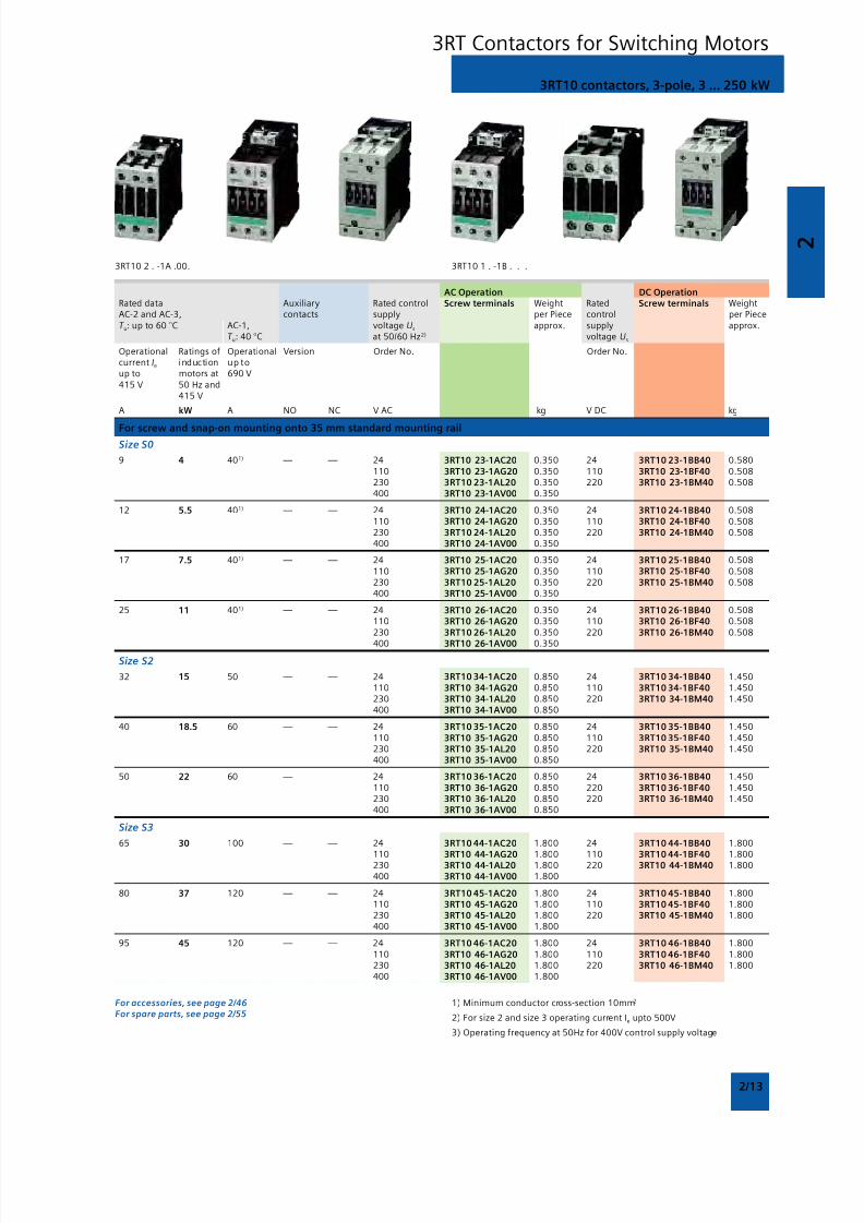
9 4 401) — — 24 3RT10 23-1AC20 0.350 24 3RT10 23-1BB40 0.580110 3RT10 23-1AG20 0.350 110 3RT10 23-1BF40 0.508230 3RT10 23-1AL20 0.350 220 3RT10 23-1BM40 0.508400 3RT10 23-1AV00 0.350
12 5.5 401) — — 24 3RT10 24-1AC20 0.350 24 3RT10 24-1BB40 0.508110 3RT10 24-1AG20 0.350 110 3RT10 24-1BF40 0.508230 3RT10 24-1AL20 0.350 220 3RT10 24-1BM40 0.508400 3RT10 24-1AV00 0.350
17 7.5 401) — — 24 3RT10 25-1AC20 0.350 24 3RT10 25-1BB40 0.508110 3RT10 25-1AG20 0.350 110 3RT10 25-1BF40 0.508230 3RT10 25-1AL20 0.350 220 3RT10 25-1BM40 0.508400 3RT10 25-1AV00 0.350
25 11 401) — — 24 3RT10 26-1AC20 0.350 24 3RT10 26-1BB40 0.508110 3RT10 26-1AG20 0.350 110 3RT10 26-1BF40 0.508230 3RT10 26-1AL20 0.350 220 3RT10 26-1BM40 0.508
400 3RT10 26-1AV00 0.350
Size S2
32 15 50 — — 24 3RT10 34-1AC20 0.850 24 3RT10 34-1BB40 1.450110 3RT10 34-1AG20 0.850 110 3RT10 34-1BF40 1.450230 3RT10 34-1AL20 0.850 220 3RT10 34-1BM40 1.450400 3RT10 34-1AV00 0.850
40 18.5 60 — — 24 3RT10 35-1AC20 0.850 24 3RT10 35-1BB40 1.450110 3RT10 35-1AG20 0.850 110 3RT10 35-1BF40 1.450230 3RT10 35-1AL20 0.850 220 3RT10 35-1BM40 1.450400 3RT10 35-1AV00 0.850
50 22 60 — — 24 3RT10 36-1AC20 0.850 24 3RT10 36-1BB40 1.450110 3RT10 36-1AG20 0.850 220 3RT10 36-1BF40 1.450230 3RT10 36-1AL20 0.850 220 3RT10 36-1BM40 1.450400 3RT10 36-1AV00 0.850
Size S3
65 30 100 — — 24 3RT10 44-1AC20 1.800 24 3RT10 44-1BB40 1.800
110 3RT10 44-1AG20 1.800 110 3RT10 44-1BF40 1.800230 3RT10 44-1AL20 1.800 220 3RT10 44-1BM40 1.800400 3RT10 44-1AV00 1.800
80 37 120 — — 24 3RT10 45-1AC20 1.800 24 3RT10 45-1BB40 1.800110 3RT10 45-1AG20 1.800 110 3RT10 45-1BF40 1.800230 3RT10 45-1AL20 1.800 220 3RT10 45-1BM40 1.800400 3RT10 45-1AV00 1.800
95 45 120 — — 24 3RT10 46-1AC20 1.800 24 3RT10 46-1BB40 1.800110 3RT10 46-1AG20 1.800 110 3RT10 46-1BF40 1.800230 3RT10 46-1AL20 1.800 220 3RT10 46-1BM40 1.800400 3RT10 46-1AV00 1.800
For accessories, see page 2/46For spare parts, see page 2/55
1) Minimum conductor cross-section 10mm2
2) For size 2 and size 3 operating current Ie upto 500V
3) Operating frequency at 50Hz for 400V control supply voltage
3RT10 contactors, 3-pole, 3 ... 250 kW
3RT Contactors for Switching Motors
8/12/2019 SIRIUS Datasheet P-1
http://slidepdf.com/reader/full/sirius-datasheet-p-1 30/100
2
2/14
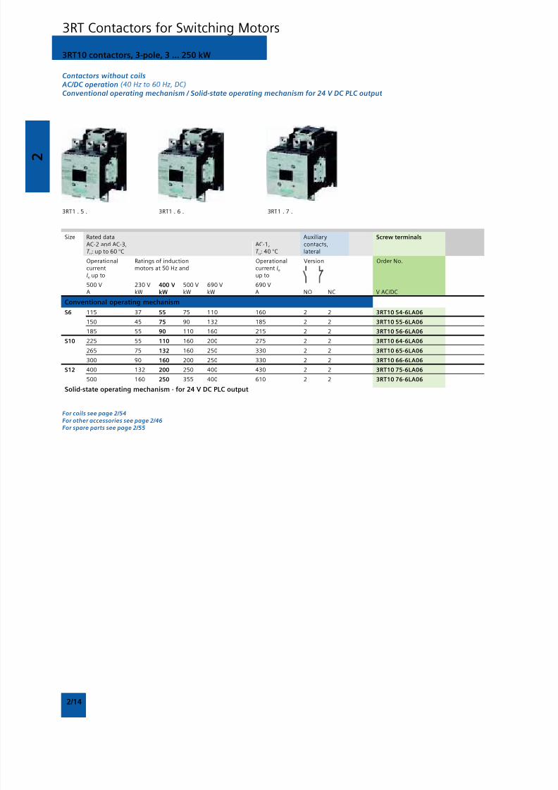
Contactors without coils AC/DC operation (40 Hz to 60 Hz, DC)Conventional operating mechanism / Solid-state operating mechanism for 24 V DC PLC output
3RT1 . 5 . 3RT1 . 6 . 3RT1 . 7 .
Size Rated data Auxiliary Screw terminalsAC-2 and AC-3, AC-1, contacts,T u: up to 60 °C T u: 40 °C lateral
Operational Ratings of induction Operational Version Order No.current motors at 50 Hz and current Ie
Ie up to up to 500 V 230 V 400 V 500 V 690 V 690 V A kW kW kW kW A NO NC V AC/DC
Conventional operating mechanism
S6 115 37 55 75 110 160 2 2 3RT10 54-6LA06
150 45 75 90 132 185 2 2 3RT10 55-6LA06
185 55 90 110 160 215 2 2 3RT10 56-6LA06
S10 225 55 110 160 200 275 2 2 3RT10 64-6LA06
265 75 132 160 250 330 2 2 3RT10 65-6LA06
300 90 160 200 250 330 2 2 3RT10 66-6LA06
S12 400 132 200 250 400 430 2 2 3RT10 75-6LA06
500 160 250 355 400 610 2 2 3RT10 76-6LA06
Solid-state operating mechanism · for 24 V DC PLC output
For coils see page 2/54For other accessories see page 2/46For spare parts see page 2/55
3RT10 contactors, 3-pole, 3 ... 250 kW
3RT Contactors for Switching Motors
8/12/2019 SIRIUS Datasheet P-1
http://slidepdf.com/reader/full/sirius-datasheet-p-1 31/100
2
2/15
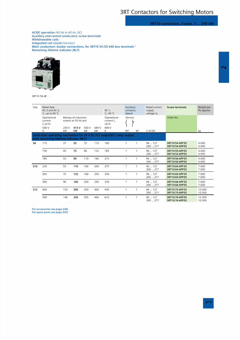
AC/DC operation (40 Hz to 60 Hz, DC) Auxiliary and control conductors: screw terminalsWithdrawable coilsIntegrated coil circuit (Varistor)Main conductors: busbar connections, for 3RT10 54 (55 kW) box terminals 1)
Remaining lifetime indicator (RLT)
3RT10 56-6P . .
Size Rated data Auxiliary Rated control Screw terminals Weight perAC-2 and AC-3, AC-1, contacts, supply PU approx.T u: up to 60 °C T u: 40 °C lateral voltage Us
Operational Ratings of induction Operational Version Order No.current motors at 50 Hz and current Ie
Ie up to up to
500 V 230 V 415 V 500 V 690 V 690 V A kW kW kW kW A NO NC V AC/DC kg
Solid-state operating mechanism for 24 V DC PLC output/PLC relay output,with remaining lifetime indicator (RLT)
S6 115 37 55 75 110 160 1 1 96 … 127 3RT10 54-6PF35 4.000200 … 277 3RT10 54-6PP35 4.000
150 45 75 90 132 185 1 1 96 … 127 3RT10 55-6PF35 4.000200 … 277 3RT10 55-6PP35 4.000
185 55 90 110 160 215 1 1 96 … 127 3RT10 56-6PF35 4.000200 … 277 3RT10 56-6PP35 4.000
S10 225 55 110 160 200 275 1 1 96 … 127 3RT10 64-6PF35 7.000200 … 277 3RT10 64-6PP35 7.000
265 75 132 160 250 330 1 1 96 … 127 3RT10 65-6PF35 7.000200 … 277 3RT10 65-6PP35 7.000
300 90 160 200 250 330 1 1 96 … 127 3RT10 66-6PF35 7.000200 … 277 3RT10 66-6PP35 7.000
S12 400 132 200 250 400 430 1 1 96 … 127 3RT10 75-6PF35 10.500200 … 277 3RT10 75-6PP35 10.500
500 160 250 355 400 610 1 1 96 … 127 3RT10 76-6PF35 10.500200 … 277 3RT10 76-6PP35 10.500
For accessories see page 2/46.For spare parts see page 2/55.
3RT10 contactors, 3-pole, 3 ... 250 kW
3RT Contactors for Switching Motors
8/12/2019 SIRIUS Datasheet P-1
http://slidepdf.com/reader/full/sirius-datasheet-p-1 32/100
2
2/16
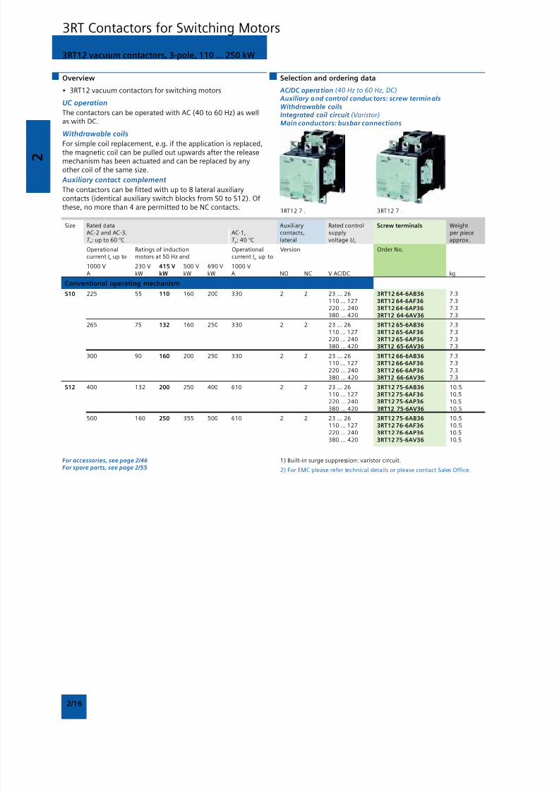
3RT12 vacuum contactors, 3-pole, 110 ... 250 kW
Overview
• 3RT12 vacuum contactors for switching motors
UC operation
The contactors can be operated with AC (40 to 60 Hz) as wellas with DC.
Withdrawable coils
For simple coil replacement, e.g. if the application is replaced,the magnetic coil can be pulled out upwards after the releasemechanism has been actuated and can be replaced by anyother coil of the same size.
Auxiliary contact complement
The contactors can be fitted with up to 8 lateral auxiliarycontacts (identical auxiliary switch blocks from S0 to S12). Ofthese, no more than 4 are permitted to be NC contacts.
Selection and ordering data
AC/DC operation (40 Hz to 60 Hz, DC) Auxiliary and control conductors: screw terminalsWithdrawable coilsIntegrated coil circuit (Varistor)Main conductors: busbar connections
3RT12 7 . 3RT12 7 .
Size Rated data Auxiliary Rated control Screw terminals WeightAC-2 and AC-3, AC-1, contacts, supply per pieceT u: up to 60 °C T u: 40 °C lateral voltage Us approx.
Operational Ratings of induction Operational Version Order No.current Ie up to motors at 50 Hz and current Ie up to
1000 V 230 V 415 V 500 V 690 V 1000 V A kW kW kW kW A NO NC V AC/DC kg
Conventional operating mechanism
S10 225 55 110 160 200 330 2 2 23 … 26 3RT12 64-6AB36 7.3110 … 127 3RT12 64-6AF36 7.3220 … 240 3RT12 64-6AP36 7.3380 … 420 3RT12 64-6AV36 7.3
265 75 132 160 250 330 2 2 23 … 26 3RT12 65-6AB36 7.3110 … 127 3RT12 65-6AF36 7.3220 … 240 3RT12 65-6AP36 7.3380 … 420 3RT12 65-6AV36 7.3
300 90 160 200 250 330 2 2 23 … 26 3RT12 66-6AB36 7.3110 … 127 3RT12 66-6AF36 7.3220 … 240 3RT12 66-6AP36 7.3380 … 420 3RT12 66-6AV36 7.3
S12 400 132 200 250 400 610 2 2 23 … 26 3RT12 75-6AB36 10.5110 … 127 3RT12 75-6AF36 10.5220 … 240 3RT12 75-6AP36 10.5380 … 420 3RT12 75-6AV36 10.5
500 160 250 355 500 610 2 2 23 … 26 3RT12 75-6AB36 10.5110 … 127 3RT12 76-6AF36 10.5220 … 240 3RT12 76-6AP36 10.5380 … 420 3RT12 75-6AV36 10.5
For accessories, see page 2/46For spare parts, see page 2/55
1) Built-in surge suppression: varistor circuit.
2) For EMC please refer technical details or please contact Sales Office.
3RT Contactors for Switching Motors
8/12/2019 SIRIUS Datasheet P-1
http://slidepdf.com/reader/full/sirius-datasheet-p-1 33/100
2
2/17
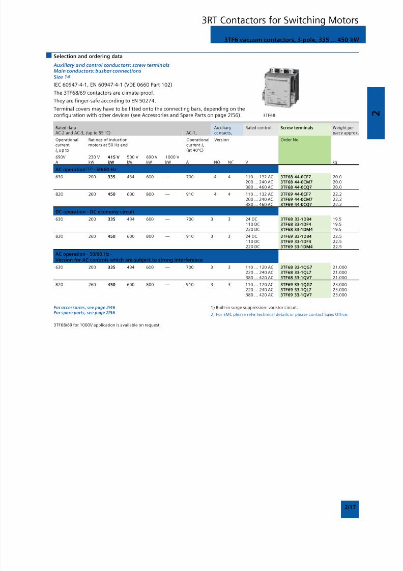
Selection and ordering data
Auxiliary and control conductors: screw terminalsMain conductors: busbar connectionsSize 14
IEC 60947-4-1, EN 60947-4-1 (VDE 0660 Part 102)
The 3TF68/69 contactors are climate-proof.
They are finger-safe according to EN 50274.
Terminal covers may have to be fitted onto the connecting bars, depending on theconfiguration with other devices (see Accessories and Spare Parts on page 2/56). 3TF68
Rated data Auxiliary Rated control Screw terminals Weight perAC-2 and AC-3, ( up to 55 °C) AC-1, contacts, piece approx.
Operational Ratings of induction Operational Version Order No.current motors at 50 Hz and current Ie
Ie up to (at 40°C)
690V 230 V 415 V 500 V 690 V 1000 VA kW kW kW kW kW A NO NC V kg
AC operation1 ) 2 ) · 50/60 Hz
630 200 335 434 600 — 700 4 4 110 … 132 AC 3TF68 44-0CF7 20.0200 … 240 AC 3TF68 44-0CM7 20.0380 … 460 AC 3TF68 44-0CQ7 20.0
820 260 450 600 800 — 910 4 4 110 … 132 AC 3TF69 44-0CF7 22.2
200 … 240 AC 3TF69 44-0CM7 22.2380 … 460 AC 3TF69 44-0CQ7 22.2
DC operation · DC economy circuit
630 200 335 434 600 — 700 3 3 24 DC 3TF68 33-1DB4 19.5110 DC 3TF68 33-1DF4 19.5220 DC 3TF68 33-1DM4 19.5
820 260 450 600 800 — 910 3 3 24 DC 3TF69 33-1DB4 22.5110 DC 3TF69 33-1DF4 22.5220 DC 3TF69 33-1DM4 22.5
AC operation · 50/60 Hz ·Version for AC controls which are subject to strong interference
630 200 335 434 600 — 700 3 3 110 ... 120 AC 3TF68 33-1QG7 21.000220 ... 240 AC 3TF68 33-1QL7 21.000380 ... 420 AC 3TF68 33-1QV7 21.000
820 260 450 600 800 — 910 3 3 110 ... 120 AC 3TF69 33-1QG7 23.000220 ... 240 AC 3TF69 33-1QL7 23.000380 ... 420 AC 3TF69 33-1QV7 23.000
3TF6 vacuum contactors, 3-pole, 335 ... 450 kW
3RT Contactors for Switching Motors
For accessories, see page 2/46For spare parts, see page 2/56
1) Built-in surge suppression: varistor circuit.
2) For EMC please refer technical details or please contact Sales Office.
3TF68/69 for 1000V application is available on request.
8/12/2019 SIRIUS Datasheet P-1
http://slidepdf.com/reader/full/sirius-datasheet-p-1 34/100
2
2/18
Overview
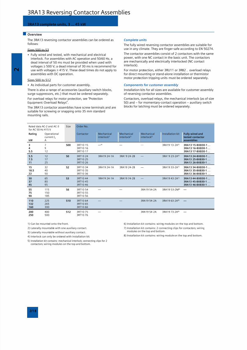
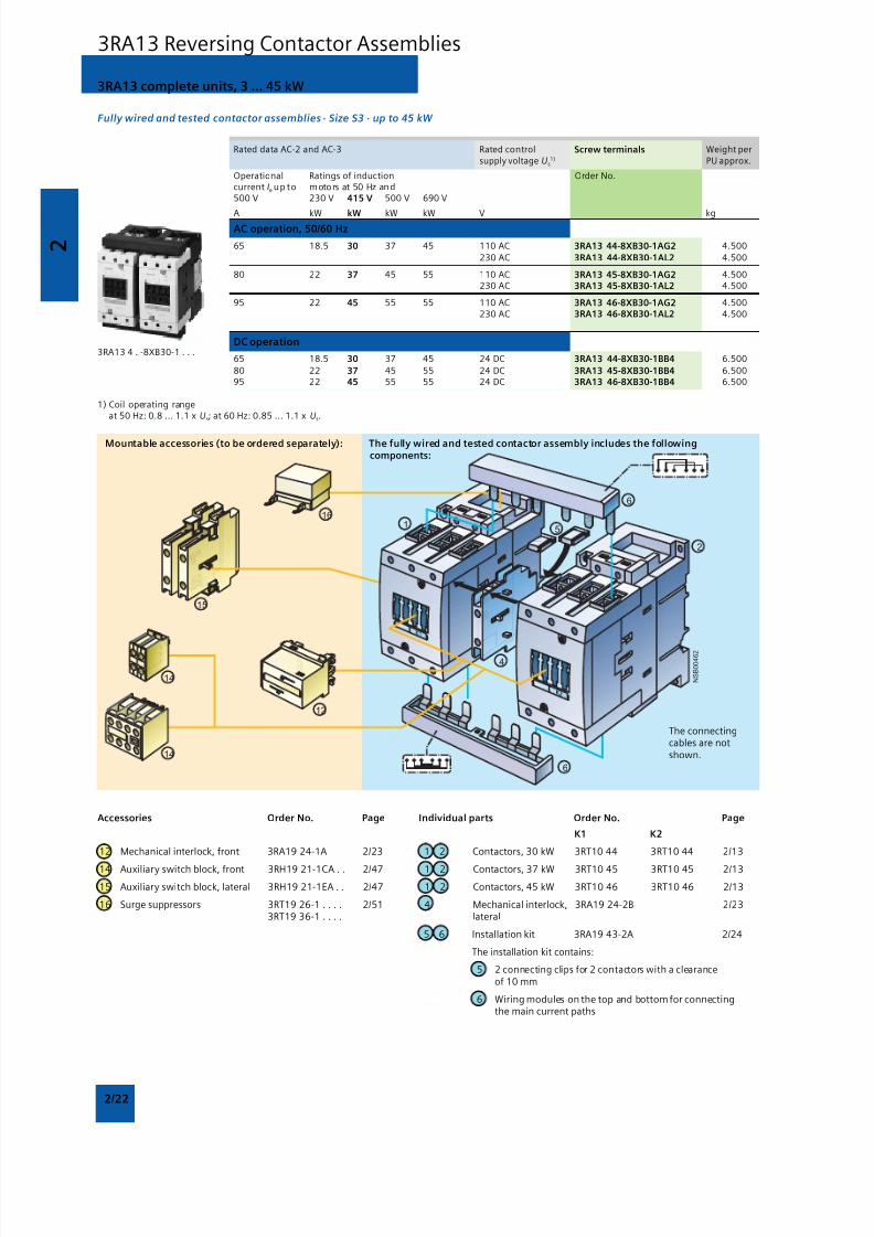
3RA13 complete units, 3 ... 45 kW
The 3RA13 reversing contactor assemblies can be ordered asfollows:
Sizes S00 to S3
• Fully wired and tested, with mechanical and electricalinterlock. For assemblies with AC operation and 50/60 Hz, a
dead interval of 50 ms must be provided when used withvoltages ≥ 500 V; a dead interval of 30 ms is recommend foruse with voltages ≥ 415 V. These dead times do not apply toassemblies with DC operation.
Sizes S00 to S12
• As individual parts for customer assembly.
There is also a range of accessories (auxiliary switch blocks,surge suppressors, etc.) that must be ordered separately.
For overload relays for motor protection, see “ProtectionEquipment: Overload Relays”.
The 3RA13 contactor assemblies have screw terminals and aresuitable for screwing or snapping onto 35 mm standardmounting rails.
Complete units
The fully wired reversing contactor assemblies are suitable foruse in any climate. They are finger-safe according to EN 50274.
The contactor assemblies consist of 2 contactors with the samepower, with one NC contact in the basic unit. The contactors
are mechanically and electrically interlocked (NC contactinterlock).
For motor protection, either 3RU11 or 3RB2 . overload relaysfor direct mounting or stand-alone installation or thermistormotor protection tripping units must be ordered separately.
Components for customer assembly
Installation kits for all sizes are available for customer assemblyof reversing contactor assemblies.
Contactors, overload relays, the mechanical interlock (as of sizeS0) and – for momentary-contact operation – auxiliary switchblocks for latching must be ordered separately.
Rated data AC-2 and AC-3 Size Order No.for AC 50 Hz 415 V
Rating Operational Contactor Mechanical Mechanical Mechanical Installation kit Fully wired andcurrent Ie interlock1) interlock2) interlock3) tested contactor
kW A assemblies
3 7 S00 3RT10 15 — 4) — — 3RA19 13-2A5) 3RA13 15-8XB30-1 . .4 9 3RT10 16 3RA13 16-8XB30-1 . .5.5 12 3RT10 17 3RA13 17-8XB30-1 . .
5.5 12 S0 3RT10 24 3RA19 24-1A 3RA19 24-2B — 3RA19 23-2A6) 3RA13 24-8XB30-1 . .7.5 17 3RT10 25 3RA13 25-8XB30-1 . .11 25 3RT10 26 3RA13 26-8XB30-1 . .
15 32 S2 3RT10 34 3RA19 24-1A 3RA19 24-2B — 3RA19 33-2A7) 3RA13 34-8XB30-1 . .18.5 40 3RT10 35 3RA13 35-8XB30-1 . .22 50 3RT10 36 3RA13 36-8XB30-1 . .
30 65 S3 3RT10 44 3RA19 24-1A 3RA19 24-2B — 3RA19 43-2A7) 3RA13 44-8XB30-1 . .37 80 3RT10 45 3RA13 45-8XB30-1 . .
45 95 3RT10 46 3RA13 46-8XB30-1 . .
55 115 S6 3RT10 54 — — 3RA19 54-2A 3RA19 53-2M8) — 75 150 3RT10 5590 185 3RT10 56
110 225 S10 3RT10 64 — — 3RA19 54-2A 3RA19 63-2A8) — 132 265 3RT10 65
160 300 3RT10 66
200 400 S12 3RT10 75 — — 3RA19 54-2A 3RA19 73-2A8) — 250 500 3RT10 76
3RA13 Reversing Contactor Assemblies
1) Can be mounted onto the front.
2) Laterally mountable with one auxiliary contact.
3) Laterally mountable without auxiliary contact.
4) Interlock can only be ordered with installation kit.
5) Installation kit contains: mechanical interlock; connecting clips for 2
contactors; wiring modules on the top and bottom.
6) Installation kit contains: wiring modules on the top and bottom.
7) Installation kit contains: 2 connecting clips for contactors; wiringmodules on the top and bottom.
8) Installation kit contains: wiring module on the top and bottom.
8/12/2019 SIRIUS Datasheet P-1
http://slidepdf.com/reader/full/sirius-datasheet-p-1 35/100
2
2/19
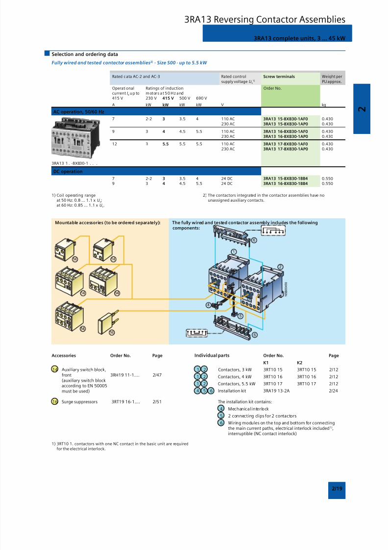
3RA13 complete units, 3 ... 45 kW
Selection and ordering data
Fully wired and tested contactor assemblies2) · Size S00 · up to 5.5 kW
Rated data AC-2 and AC-3 Rated control Screw terminals Weight persupply voltage Us
1) PU approx.
Operational Ratings of induction Order No.current Ie up to motors at 50 Hz and415 V 230 V 415 V 500 V 690 V
A kW kW kW kW V kg
AC operation, 50/60 Hz
7 2-2 3 3.5 4 110 AC 3RA13 15-8XB30-1AF0 0.430230 AC 3RA13 15-8XB30-1AP0 0.430
9 3 4 4.5 5.5 110 AC 3RA13 16-8XB30-1AF0 0.430230 AC 3RA13 16-8XB30-1AP0 0.430
12 3 5.5 5.5 5.5 110 AC 3RA13 17-8XB30-1AF0 0.430230 AC 3RA13 17-8XB30-1AP0 0.430
DC operation
7 2-2 3 3.5 4 24 DC 3RA13 15-8XB30-1BB4 0.5509 3 4 4.5 5.5 24 DC 3RA13 16-8XB30-1BB4 0.550
3RA13 1 . -8XB30-1 . . .
1) Coil operating rangeat 50 Hz: 0.8 ... 1.1 x Us;at 60 Hz: 0.85 ... 1.1 x Us.
2) The contactors integrated in the contactor assemblies have nounassigned auxiliary contacts.
Accessories Order No. Page Individual parts Order No. Page
K1 K2
14 Auxiliary switch block, 1 2 Contactors, 3 kW 3RT10 15 3RT10 15 2/12front 3RH19 11-1.... 2/47 1 2 Contactors, 4 kW 3RT10 16 3RT10 16 2/12(auxiliary switch block
1 2 Contactors, 5.5 kW 3RT10 17 3RT10 17 2/12according to EN 500054 5 6 Installation kit 3RA19 13-2A 2/24must be used)
16 Surge suppressors 3RT19 16-1.... 2/51 The installation kit contains:
4 Mechanical interlock
5 2 connecting clips for 2 contactors
6 Wiring modules on the top and bottom for connectingthe main current paths, electrical interlock included1),interruptible (NC contact interlock)
1) 3RT10 1. contactors with one NC contact in the basic unit are requiredfor the electrical interlock.
Mountable accessories (to be ordered separately): The fully wired and tested contactor assembly includes the followingcomponents:
3RA13 Reversing Contactor Assemblies
8/12/2019 SIRIUS Datasheet P-1
http://slidepdf.com/reader/full/sirius-datasheet-p-1 36/100
8/12/2019 SIRIUS Datasheet P-1
http://slidepdf.com/reader/full/sirius-datasheet-p-1 37/100
2
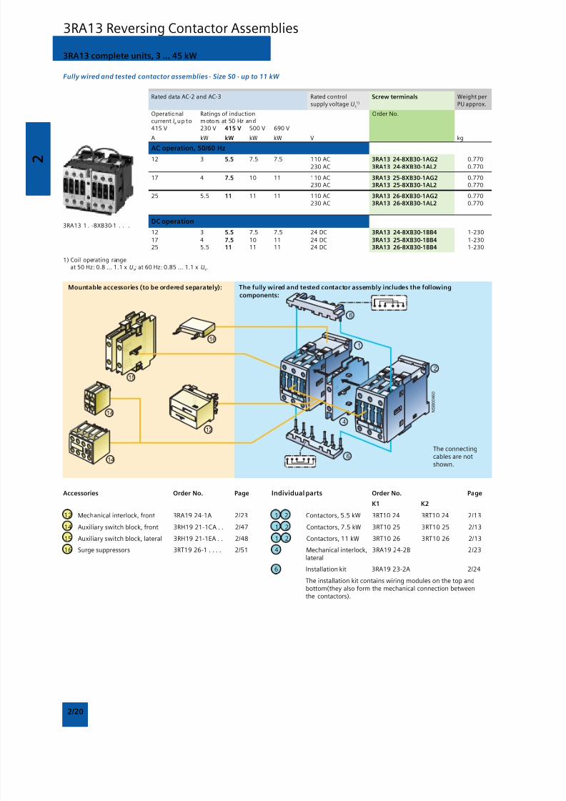
2/21
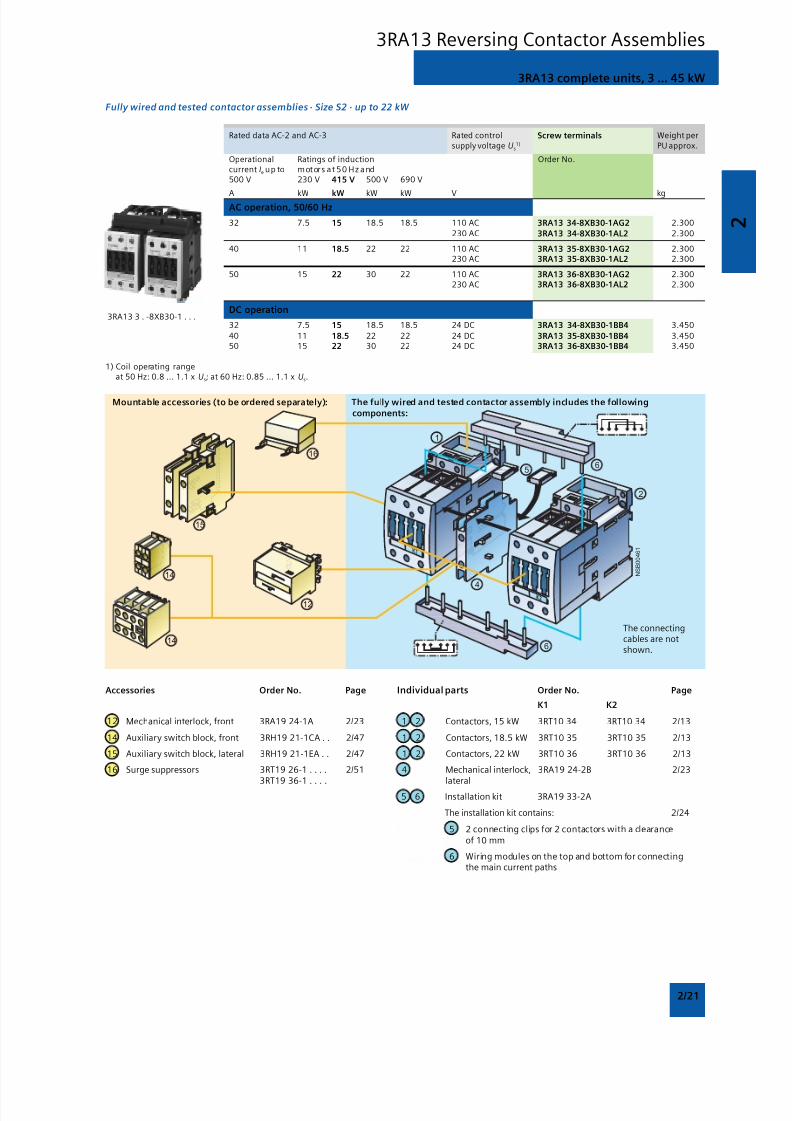
3RA13 complete units, 3 ... 45 kW
Fully wired and tested contactor assemblies · Size S2 · up to 22 kW
Rated data AC-2 and AC-3 Rated control Screw terminals Weight persupply voltage Us
1) PU approx.
Operational Ratings of induction Order No.current Ie up to motors at 50 Hz and500 V 230 V 415 V 500 V 690 V
A kW kW kW kW V kgAC operation, 50/60 Hz
32 7.5 15 18.5 18.5 110 AC 3RA13 34-8XB30-1AG2 2.300
230 AC 3RA13 34-8XB30-1AL2 2.300
40 11 18.5 22 22 110 AC 3RA13 35-8XB30-1AG2 2.300230 AC 3RA13 35-8XB30-1AL2 2.300
50 15 22 30 22 110 AC 3RA13 36-8XB30-1AG2 2.300230 AC 3RA13 36-8XB30-1AL2 2.300
DC operation
32 7.5 15 18.5 18.5 24 DC 3RA13 34-8XB30-1BB4 3.450
40 11 18.5 22 22 24 DC 3RA13 35-8XB30-1BB4 3.45050 15 22 30 22 24 DC 3RA13 36-8XB30-1BB4 3.450
1) Coil operating rangeat 50 Hz: 0.8 ... 1.1 x Us; at 60 Hz: 0.85 ... 1.1 x Us.
3RA13 3 . -8XB30-1 . . .
Mountable accessories (to be ordered separately): The fully wired and tested contactor assembly includes the followingcomponents:
The connectingcables are notshown.
Accessories Order No. Page Individual parts Order No. Page
K1 K2
12 Mechanical interlock, front 3RA19 24-1A 2/23 1 2 Contactors, 15 kW 3RT10 34 3RT10 34 2/13
14 Auxiliary switch block, front 3RH19 21-1CA . . 2/47 1 2 Contactors, 18.5 kW 3RT10 35 3RT10 35 2/13
15 Auxiliary switch block, lateral 3RH19 21-1EA . . 2/47 1 2 Contactors, 22 kW 3RT10 36 3RT10 36 2/13
16 Surge suppressors 3RT19 26-1 . . . . 2/51 4 Mechanical interlock, 3RA19 24-2B 2/233RT19 36-1 . . . . lateral
5 6 Installation kit 3RA19 33-2A
The installation kit contains: 2/24
5 2 connecting clips for 2 contactors with a clearanceof 10 mm
6 Wiring modules on the top and bottom for connectingthe main current paths
3RA13 Reversing Contactor Assemblies
8/12/2019 SIRIUS Datasheet P-1
http://slidepdf.com/reader/full/sirius-datasheet-p-1 38/100
2
2/22
Mountable accessories (to be ordered separately): The fully wired and tested contactor assembly includes the followingcomponents:
The connectingcables are notshown.
3RA13 complete units, 3 ... 45 kW
Fully wired and tested contactor assemblies · Size S3 · up to 45 kW
Rated data AC-2 and AC-3 Rated control Screw terminals Weight persupply voltage Us
1) PU approx.
Operational Ratings of induction Order No.current Ie up to motors at 50 Hz and500 V 230 V 415 V 500 V 690 V
A kW kW kW kW V kgAC operation, 50/60 Hz
65 18.5 30 37 45 110 AC 3RA13 44-8XB30-1AG2 4.500
230 AC 3RA13 44-8XB30-1AL2 4.500
80 22 37 45 55 110 AC 3RA13 45-8XB30-1AG2 4.500230 AC 3RA13 45-8XB30-1AL2 4.500
95 22 45 55 55 110 AC 3RA13 46-8XB30-1AG2 4.500230 AC 3RA13 46-8XB30-1AL2 4.500
DC operation
65 18.5 30 37 45 24 DC 3RA13 44-8XB30-1BB4 6.500
80 22 37 45 55 24 DC 3RA13 45-8XB30-1BB4 6.50095 22 45 55 55 24 DC 3RA13 46-8XB30-1BB4 6.500
1) Coil operating rangeat 50 Hz: 0.8 ... 1.1 x Us; at 60 Hz: 0.85 ... 1.1 x Us.
3RA13 4 . -8XB30-1 . . .
Accessories Order No. Page Individual parts Order No. Page
K1 K2
12 Mechanical interlock, front 3RA19 24-1A 2/23 1 2 Contactors, 30 kW 3RT10 44 3RT10 44 2/13
14 Auxiliary switch block, front 3RH19 21-1CA . . 2/47 1 2 Contactors, 37 kW 3RT10 45 3RT10 45 2/13
15 Auxiliary switch block, lateral 3RH19 21-1EA . . 2/47 1 2 Contactors, 45 kW 3RT10 46 3RT10 46 2/13
16 Surge suppressors 3RT19 26-1 . . . . 2/51 4 Mechanical interlock, 3RA19 24-2B 2/233RT19 36-1 . . . . lateral
5 6 Installation kit 3RA19 43-2A 2/24
The installation kit contains:
5 2 connecting clips for 2 contactors with a clearanceof 10 mm
6 Wiring modules on the top and bottom for connectingthe main current paths
3RA13 Reversing Contactor Assemblies

8/12/2019 SIRIUS Datasheet P-1
http://slidepdf.com/reader/full/sirius-datasheet-p-1 39/100
2
2/23
Components for customer assembly
For Size Version Order No. Weight percontactors PU approx.
Type kg
Mechanical interlocks
3RT10 2 S0 For lateral mounting1) 3RA19 24-2B 0.0603RT10 3 S2 Each with one auxiliary contact (1 NC contact)3RT10 4 S3 per contactor (can only be used to connect3RT13 2 contactors which are not more than 1 size3RT13 3 larger or smaller. The mounting depth of the3RT13 4 smaller contactor has to be adapted.)3RT15 23RT15 3
3RT10 2 S0 For mounting to the front2) 3RA19 24-1A 0.0503RT10 3 S2 Onto contactors with sizes S0 to S33RT10 4 S3 (for contactors of the same s ize)3RT13 2 S0 Note:3RT15 2 Size S0: Wiring modules must be mounted first
Sizes S2 and S3: Use 3RA19 32-2C mechanical connectors
3RT1 . 5 S6 For lateral mounting 3RA19 54-2A 0.050to S10 Without auxiliary contacts; size S6, S10 and3RT1 . 7 S12 S12 contactors can be interlocked with each other
as required; no adaptation of mounting depthis necessary. Contactor clearance 10 mm.
3RT10 4 . -A S3 Adapters, laterally mountable 3RA19 54-2C 0.050with with For mechanical interlocking of contactor S33RT10 5 S6 (only for AC operation) with contactor S6 using
3RA19 54-2A locking device (must be orderedseparately) incl. connecting clips.
Base plates
3RT10 5 S6 For customer assembly of reversing 3RA19 52-2A 1.3003RT1 . 6 S10 contactor assemblies 3RA19 62-2A 2.1003RT1 . 7 S12 3RA19 72-2A 2.300
1) Can also be used for 4-pole contactors with sizes S2 and S3.
2) Can also be used for size S0 4-pole contactors.
Selection and ordering data
3RA19 24-1A mountedonto 2 contactors
3RA19 54-2A
3RA19 54-2C
3RA13 Reversing Contactor Assemblies
8/12/2019 SIRIUS Datasheet P-1
http://slidepdf.com/reader/full/sirius-datasheet-p-1 40/100
2
2/24
For Size Version Order No. Weight percontactors PU approx.
Type kg
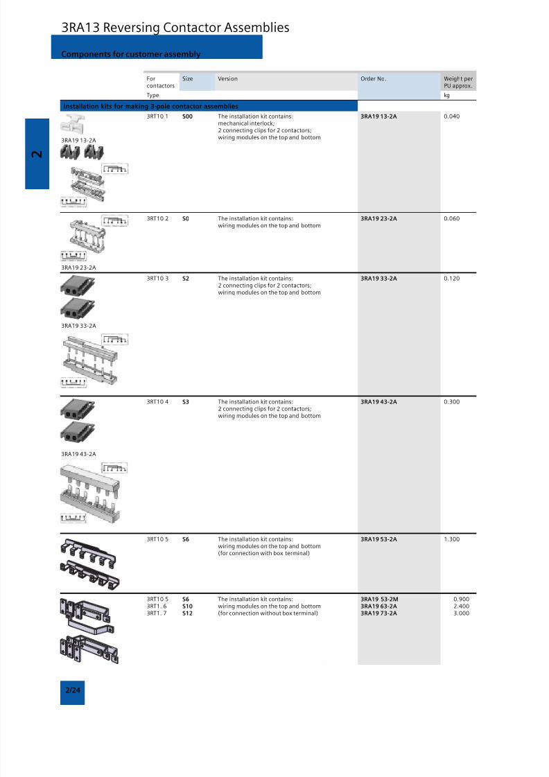
Installation kits for making 3-pole contactor assemblies
3RT10 1 S00 The installation kit contains: 3RA19 13-2A 0.040mechanical interlock;2 connecting clips for 2 contactors;
wiring modules on the top and bottom
3RT10 2 S0 The installation kit contains: 3RA19 23-2A 0.060wiring modules on the top and bottom
3RT10 3 S2 The installation kit contains: 3RA19 33-2A 0.1202 connecting clips for 2 contactors;wiring modules on the top and bottom
3RT10 4 S3 The installation kit contains: 3RA19 43-2A 0.300
2 connecting clips for 2 contactors;wiring modules on the top and bottom
3RT10 5 S6 The installation kit contains: 3RA19 53-2A 1.300
wiring modules on the top and bottom(for connection with box terminal)
3RT10 5 S6 The installation kit contains: 3RA19 53-2M 0.9003RT1. 6 S10 wiring modules on the top and bottom 3RA19 63-2A 2.4003RT1. 7 S12 (for connection without box terminal) 3RA19 73-2A 3.000
3RA19 13-2A
3RA19 23-2A
3RA19 33-2A
3RA19 43-2A
Components for customer assembly
3RA13 Reversing Contactor Assemblies
8/12/2019 SIRIUS Datasheet P-1
http://slidepdf.com/reader/full/sirius-datasheet-p-1 41/100
2
2/25
For Size Contactor Version Order No. Weight percontactors clearance PU approx.
Type mm kg
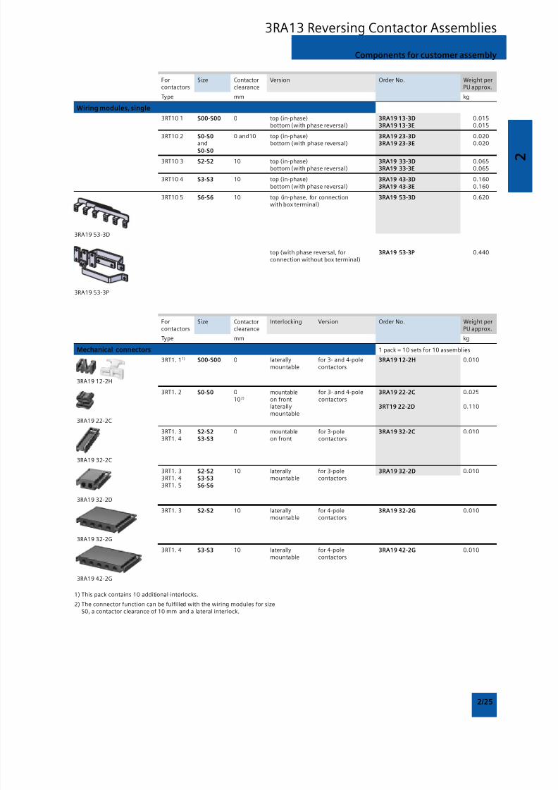
Wiring modules, single
3RT10 1 S00-S00 0 top (in-phase) 3RA19 13-3D 0.015bottom (with phase reversal) 3RA19 13-3E 0.015
3RT10 2 S0-S0 0 and10 top (in-phase) 3RA19 23-3D 0.020and bottom (with phase reversal) 3RA19 23-3E 0.020
S0-S0
3RT10 3 S2-S2 10 top (in-phase) 3RA19 33-3D 0.065bottom (with phase reversal) 3RA19 33-3E 0.065
3RT10 4 S3-S3 10 top (in-phase) 3RA19 43-3D 0.160bottom (with phase reversal) 3RA19 43-3E 0.160
3RT10 5 S6-S6 10 top (in-phase, for connection 3RA19 53-3D 0.620with box terminal)
top (with phase reversal, for 3RA19 53-3P 0.440connection without box terminal)
3RA19 53-3D
3RA19 53-3P
For Size Contactor Interlocking Version Order No. Weight percontactors clearance PU approx.
Type mm kg
Mechanical connectors 1 pack = 10 sets for 10 assemblies
3RT1. 11) S00-S00 0 laterally for 3- and 4-pole 3RA19 12-2H 0.010mountable contactors
3RA19 12-2H
3RT1. 2 S0-S0 0 mountable for 3- and 4-pole 3RA19 22-2C 0.025102) on front contactors
laterally 3RT19 22-2D 0.110
mountable3RA19 22-2C
3RT1. 3 S2-S2 0 mountable for 3-pole 3RA19 32-2C 0.0103RT1. 4 S3-S3 on front contactors
3RA19 32-2C
3RT1. 3 S2-S2 10 laterally for 3-pole 3RA19 32-2D 0.0103RT1. 4 S3-S3 mountable contactors3RT1. 5 S6-S6
3RA19 32-2D
3RT1. 3 S2-S2 10 laterally for 4-pole 3RA19 32-2G 0.010mountable contactors
3RA19 32-2G
3RT1. 4 S3-S3 10 laterally for 4-pole 3RA19 42-2G 0.010mountable contactors
3RA19 42-2G
1) This pack contains 10 additional interlocks.
2) The connector function can be fulfilled with the wiring modules for sizeS0, a contactor clearance of 10 mm and a lateral interlock.
Components for customer assembly
3RA13 Reversing Contactor Assemblies
8/12/2019 SIRIUS Datasheet P-1
http://slidepdf.com/reader/full/sirius-datasheet-p-1 42/100
2
2/26
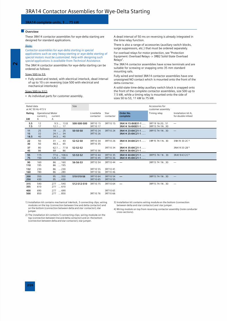
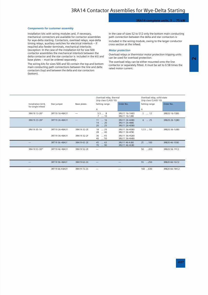
3RA14 complete units, 3 ... 75 kW
Overview
These 3RA14 contactor assemblies for wye-delta starting aredesigned for standard applications.
Note:
Contactor assemblies for wye-delta starting in specialapplications such as very heavy starting or wye-delta starting of
special motors must be customized. Help with designing suchspecial applications is available from Technical Assistance.
The 3RA14 contactor assemblies for wye-delta starting can beordered as follows:
Sizes S00 to S3:
• Fully wired and tested, with electrical interlock, dead intervalof up to 10 s on reversing (size S00 with electrical andmechanical interlocks)
Sizes S00 to S12:
• As individual parts for customer assembly.
A dead interval of 50 ms on reversing is already integrated inthe time relay function.
There is also a range of accessories (auxiliary switch blocks,surge suppressors, etc.) that must be ordered separately.
For overload relays for motor protection, see “Protection
Equipment: Overload Relays -> 3RB2 Solid-State OverloadRelays”.
The 3RA14 contactor assemblies have screw terminals and aresuitable for screwing or snapping onto 35 mm standardmounting rails.
Fully wired and tested 3RA14 contactor assemblies have oneunassigned NO contact which is mounted onto the front of thedelta contactor.
A solid-state time-delay auxiliary switch block is snapped ontothe front of the complete contactor assemblies, size S00 up to7.5 kW, while a timing relay is mounted onto the side ofsizes S0 to S3, 11 kW to 75 kW.
Rated data Size Accessories for
at AC 50 Hz 415 V customer assembly
Rating Operational Motor Line/delta Star Order No. Timing relay Installation kit A,current Ie current contactor contactor complete for double infeed
kW A A
5.5 12 9.5 ... 13.8 S00-S00-S00 3RT10 15 3RT10 15 3RA14 15-8XB31-1 . . . 3RT19 16-2G . 51 — 7.5 17 12.1 ... 17 3RT10 17 3RA14 16-8XB31-1 . . . 3RP15 74-1N . 30
11 25 19 ... 25 S0-S0-S0 3RT10 24 3RT10 24 3RA14 23-8XC21-1 . . . 3RP15 74-1N . 30 — 15 32 24.1 ... 34 3RT10 26 3RA14 25-8XC21-1 . . . 18.5 40 34.5 ... 40
22 50 31 ... 43 S2-S2-S0 3RT10 34 3RT10 26 3RA14 34-8XC21-1 . . . 3 RP 15 74 -1 N . 30 3 RA19 33 -2C 3)
30 50 48.3 ... 65 3RT10 35 —
37 80 62.1 ... 77.8 S2-S2-S2 3RT10 34 3RA14 35-8XC21-1 . . . 3RA19 33-2B 3)
45 86 69 ... 86 3RT10 36 3RA14 36-8XC21-1 . . .
55 115 77.6 ... 108.6 S3-S3-S2 3RT10 44 3RT10 35 3RA14 44-8XC21-1 . . . 3RP15 74 -1N . 30 3RA1 9 4 3-2 C 3)
75 150 120.7 ... 150 3RT10 45 3RT10 36 3RA14 45-8XC21-1 . . .
90 160 86 ... 160 S6-S6-S3 3RT10 54 3RT10 44 — 3RP15 74-1N . 30 — 110 195 86 ... 195
132 230 86 ... 230 3RT10 55 3RT10 45160 280 86 ... 280 3RT10 56 3RT10 46
200 350 95 ... 350 S10-S10-S6 3RT10 64 3RT10 54 — 3RP15 74-1N . 30 — 250 430 95 ... 430 3RT10 65 3RT10 55
315 540 277 ... 540 S12-S12-S10 3RT10 75 3RT10 64 — 3RP15 74-1N . 30 — 355 610 277 ... 610
400 690 277 ... 690 3RT10 65500 850 277 ... 850 3RT10 76 3RT10 66
1) Installation kit contains mechanical interlock, 3 connecting clips; wiringmodules on the top (connection between line and delta contactor) andon the bottom (connection between delta and star contactor); star jumper.
2) The installation kit contains 5 connecting clips; wiring modules on thetop (connection between line and delta contactor) and on the bottom(connection between delta and star contactor); star jumper.
3) Installation kit contains wiring module on the bottom (connectionbetween delta and star contactor) and star jumper.
4) Wiring module on top from reversing contactor assembly (note conductorcross-sections).
3RA14 Contactor Assemblies for Wye-Delta Starting
8/12/2019 SIRIUS Datasheet P-1
http://slidepdf.com/reader/full/sirius-datasheet-p-1 43/100
8/12/2019 SIRIUS Datasheet P-1
http://slidepdf.com/reader/full/sirius-datasheet-p-1 44/100
2
2/28
Mountable accessories (to be ordered separately): The fully wired and tested contactor assembly includes the followingcomponents:
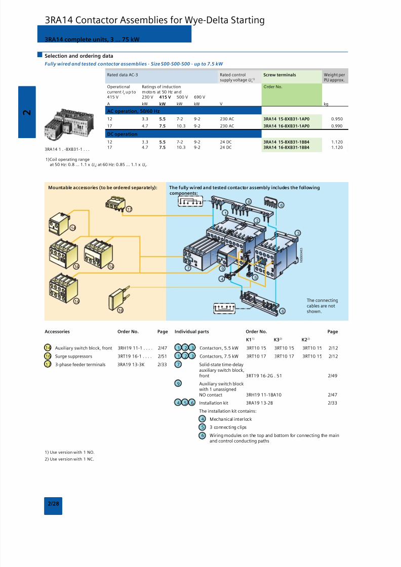
3RA14 complete units, 3 ... 75 kW
Selection and ordering data
Fully wired and tested contactor assemblies · Size S00-S00-S00 · up to 7.5 kW
Rated data AC-3 Rated control Screw terminals Weight persupply voltage Us
1) PU approx.
Operational Ratings of induction Order No.current Ie up to motors at 50 Hz and
415 V 230 V 415 V 500 V 690 VA kW kW kW kW V kg
AC operation, 50/60 Hz
12 3.3 5.5 7-2 9-2 230 AC 3RA14 15-8XB31-1AP0 0.950
17 4.7 7.5 10.3 9-2 230 AC 3RA14 16-8XB31-1AP0 0.990
DC operation
12 3.3 5.5 7-2 9-2 24 DC 3RA14 15-8XB31-1BB4 1.120
17 4.7 7.5 10.3 9-2 24 DC 3RA14 16-8XB31-1BB4 1.120
1)Coil operating rangeat 50 Hz: 0.8 ... 1.1 x Us; at 60 Hz: 0.85 ... 1.1 x Us.
3RA14 1 . -8XB31-1 . . .
Accessories Order No. Page Individual parts Order No. Page
K11) K32) K22)
14 Auxiliary switch block, front 3RH19 11-1 . . . . 2/47 1 2 3 Contactors, 5.5 kW 3RT10 15 3RT10 15 3RT10 15 2/12
16 Surge suppressors 3RT19 16-1 . . . . 2/51 1 2 3 Contactors, 7.5 kW 3RT10 17 3RT10 17 3RT10 15 2/12
17 3-phase feeder terminals 3RA19 13-3K 2/33 7 Solid-state time-delayauxiliary switch block,front 3RT19 16-2G . 51 2/49
9 Auxiliary switch blockwith 1 unassignedNO contact 3RH19 11-1BA10 2/47
4 5 6 Installation kit 3RA19 13-2B 2/33
The installation kit contains:
4 Mechanical interlock
5 3 connecting clips
6 Wiring modules on the top and bottom for connecting the mainand control conducting paths
1) Use version with 1 NO.
2) Use version with 1 NC.
The connectingcables are notshown.
3RA14 Contactor Assemblies for Wye-Delta Starting
8/12/2019 SIRIUS Datasheet P-1
http://slidepdf.com/reader/full/sirius-datasheet-p-1 45/100
2
2/29
N S B 0_
0 0 4 6 4 a
21
3
6
8
19
66
5
16
7
12
17
18
10
10
15
10
94
19
Mountable accessories (to be ordered separately): The fully wired and tested contactor assembly includes the followingcomponents:
The connecting
cables are notshown.
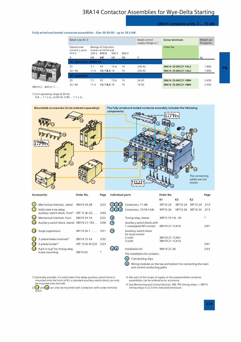
3RA14 complete units, 3 ... 75 kW
Fully wired and tested contactor assemblies · Size S0-S0-S0 · up to 18.5 kW
Rated data AC-3 Rated control Screw terminals Weight persupply voltage Us
1) PU approx.
Operational Ratings of induction Order No.current Ie up to motors at 50 Hz and415 V 230 V 415 V 500 V 690 V
A kW kW kW kW V kg
AC operation, 50/60 Hz
25 7.1 11 15.6 19 230 AC 3RA14 23-8XC21-1AL2 1.800
32 / 40 11.4 15 / 18.5 19 19 230 AC 3RA14 25-8XC21-1AL2 1.800
DC operation
25 7.1 11 15.6 19 24 DC 3RA14 23-8XC21-1BB4 2.450
32 / 40 11.4 15 / 18.5 19 19 24 DC 3RA14 25-8XC21-1BB4 2.450
1) Coil operating range at 50 Hz:0.8 ... 1.1 x Us ; at 60 Hz: 0.85 ... 1.1 x Us.
3RA14 2 . -8XC21-1 . . .
1) Generally possible. If a solid-state time-delay auxiliary switch block ismounted onto the front of K3, a standard auxiliary switch block can onlybe mounted onto the side.
2) 17 and 18 can only be mounted with contactors with screw terminal(coil).
3) Not part of the scope of supply of the preassembled contactorassemblies; can be ordered as an accessory.
4) See Monitoring and Control Devices: 3RP, 7PV timing relays -> 3RP15timing relays in 22.5 mm industrial enclosure.
Accessories Order No. Page Individual parts Order No. Page
K1 K3 K2
1 Mechanical interlock, lateral 3RA19 24-2B 2/23 1 2 3 Contactors, 11 kW 3RT10 24 3RT10 24 3RT10 24 2/13
7 Solid-state time-delay 1 2 3 Contactors, 15/18.5 kW 3RT10 26 3RT10 26 3RT10 24 2/13auxiliary switch block, front1) 3RT19 26-2G . . . 2/49
12 Mechanical interlock, front 3RA19 24-1A 2/23 8 Timing relay, lateral 3RP15 74-1N . 30 4)
15 Auxiliar y switch block, lateral 3RH19 21-1EA . . 2/48 9 Auxiliar y switch block with1 unassigned NO contact 3RH19 21-1CA10 2/47
16 Surge suppressors 3RT19 26-1 . . . . 2/51 10 Auxiliary switch blockfor local control
17 3-phase feeder terminal2)
3RV19 15-5A 2/332 units 3RH19 21-1CA01
18 3-phase busbar2) 3RT19 26-4CC20 2/333 units 3RH19 21-1CA10
2/47
19 Push-in lug3) for timing relay 5 6 Installation kit 3RA19 23-2B 2/33screw mounting 3RP19 03 4)
The installation kit contains:
5 Connecting cl ips
6 Wiring modules on the top and bottom for connecting the mainand control conducting paths
3RA14 Contactor Assemblies for Wye-Delta Starting
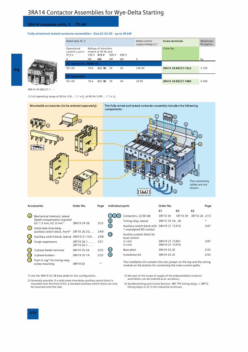
8/12/2019 SIRIUS Datasheet P-1
http://slidepdf.com/reader/full/sirius-datasheet-p-1 46/100
2
2/30
N S B 0_
0 0 4 6 5 b
2
1
3
6
11
8
6
16
7
17
18
10
10
15
10
9
4
19
Mountable accessories (to be ordered separately): The fully wired and tested contactor assembly includes the followingcomponents:
The connecting
cables are notshown.
Fully wired and tested contactor assemblies · Size S2-S2-S0 · up to 30 kW
Rated data AC-3 Rated control Screw terminals Weight persupply voltage Us
1) PU approx.
Operational Ratings of induction Order No.current Ie up to motors at 50 Hz and415 V 230 V 415 V 500 V 690 V
A kW kW kW kW V kg
AC operation, 50/60 Hz
50 / 65 19.6 22 / 30 35 34 230 AC 3RA14 34-8XC21-1AL2 3.100
DC operation
50 / 65 19.6 22 / 30 35 34 24 DC 3RA14 34-8XC21-1BB4 4.500
1) Coil operating range at 50 Hz: 0.8 ... 1.1 x Us; at 60 Hz: 0.85 ... 1.1 x U
s.
3RA14 34-8XC21-1 . . .
1) Use the 3RA19 32-2B base plate for this configuration.
2) Generally possible. If a solid-state time-delay auxiliary switch block ismounted onto the front of K3, a standard auxiliary switch block can onlybe mounted onto the side.
3) Not part of the scope of supply of the preassembled contactorassemblies; can be ordered as an accessory.
4) See Monitoring and Control Devices: 3RP, 7PV timing relays -> 3RP15timing relays in 22.5 mm industrial enclosure.
Accessories Order No. Page
4 Mechanical interlock, lateralDepth compensation requiredK3: 1.5 mm; K2: 0 mm1) 3RA19 24-2B 2/23
7 Solid-state time-delayauxiliary switch block, front2) 3RT19 26-2G . . . 2/49
15 Auxiliary switch block, lateral 3RH19 21-1EA . . 2/48
16 Surge suppressors 3RT19 26-1 . . . . 2/513RT19 36-1 . . . .
17 3-phase feeder terminal 3RV19 35-5A 2/33
18 3-phase busbars 3RV19 35-1A 2/33
19 Push-in lug3) for timing relay
screw mounting 3RP19 03 4)
Individual parts Order No. Page
K1 K3 K2
1 2 3 Contactors, 22/30 kW 3RT10 34 3RT10 34 3RT10 26 2/13
8 Timing relay, lateral 3RP15 74-1N . 30 4)
9 Auxiliary switch block with 3RH19 21-1CA10 2/471 unassigned NO contact
10 Auxiliar y switch block forlocal control2 units 3RH19 21-1CA01 2/473 units 3RH19 21-1CA10
11 Base plate 3RA19 32-2E 2/33
6 Installation kit 3RA19 33-2C 2/33
The installation kit contains the star jumper on the top and the wiringmodule on the bottom for connecting the main current paths.
3RA14 complete units, 3 ... 75 kW
3RA14 Contactor Assemblies for Wye-Delta Starting

8/12/2019 SIRIUS Datasheet P-1
http://slidepdf.com/reader/full/sirius-datasheet-p-1 47/100
2
2/31
N S B 0_
0 0 4 6 6 a
17
18
16
15
10
9
19
11
3
621
10
10
8
6
12
4
7
Mountable accessories (to be ordered separately): The fully wired and tested contactor assembly includes the followingcomponents:
The connectingcables are notshown.
Fully wired and tested contactor assemblies · Size S2-S2-S2 · up to 45 kW
Rated data AC-3 Rated control Screw terminals Weight persupply voltage Us
1) PU approx.
Operational Ratings of induction Order No.current Ie up to motors at 50 Hz and415 V 230 V 415 V 500 V 690 V
A kW kW kW kW V kg
AC operation, 50/60 Hz
80 25 37 51 63 230 AC 3RA14 35-8XC21-1AL2 3.700
86 27 45 55 63 230 AC 3RA14 36-8XC21-1AL2 3.700
DC operation
80 25 37 51 63 24 DC 3RA14 35-8XC21-1BB4 5.500
86 27 45 55 63 24 DC 3RA14 36-8XC21-1BB4 5.500
1) Coil operating range at 50 Hz: 0.8 ... 1.1 x Us; at 60 Hz: 0.85 ... 1.1 x Us.
3RA14 3 . -8XC21-1 . . .
1) Generally possible. If a solid-state time-delay auxiliary switch block ismounted onto the front of K3, a standard auxiliary switch block can onlybe mounted onto the side.
2) Not part of the scope of supply of the preassembled contactorassemblies; can be ordered as an accessory.
3) See Monitoring and Control Devices: 3RP, 7PV timing relays -> 3RP15timing relays in 22.5 mm industrial enclosure.
Accessories Order No. Page
4 Mechanical interlock, lateral 3RA19 24-2B 2/23
7 Solid-state time-delayauxiliary switch block, front1) 3RT19 26-2G . . . 2/49
12 Mechanical interlock, front 3RA19 24-1A 2/23
15 Auxiliary switch block, lateral 3RH19 21-1EA . . 2/4816 Surge suppressors 3RT19 26-1 . . . . 2/51
3RT19 36-1 . . . .
17 3-phase feeder terminals 3RV19 35-5A 2/33
18 3-phase busbars 3RV19 35-1A 2/33
19 Push-in lug2) for timing relayscrew mounting 3RP19 03 3)
Individual parts Order No. Page
K1 K3 K2
1 2 3 Contactors, 37 kW 3RT10 35 3RT10 35 3RT10 34 2/13
1 2 3 Contactors, 45 kW 3RT10 36 3RT10 36 3RT10 34 2/13
8 Timing relay, lateral 3RP15 74-1N . 30 3)
9 Auxiliary switch block with
1 unassigned NO contact 3RH19 21-1CA10 2/4710 Auxiliary switch block for
local control2 units 3RH19 21-1CA013 units 3RH19 21-1CA10 2/47
11 Base plate 3RA19 32-2F 2/33
6 Installation kit 3RA19 33-2B 2/33
The installation kit contains the star jumper on the top and the wiringmodule on the bottom for connecting the main current paths.
3RA14 complete units, 3 ... 75 kW
3RA14 Contactor Assemblies for Wye-Delta Starting
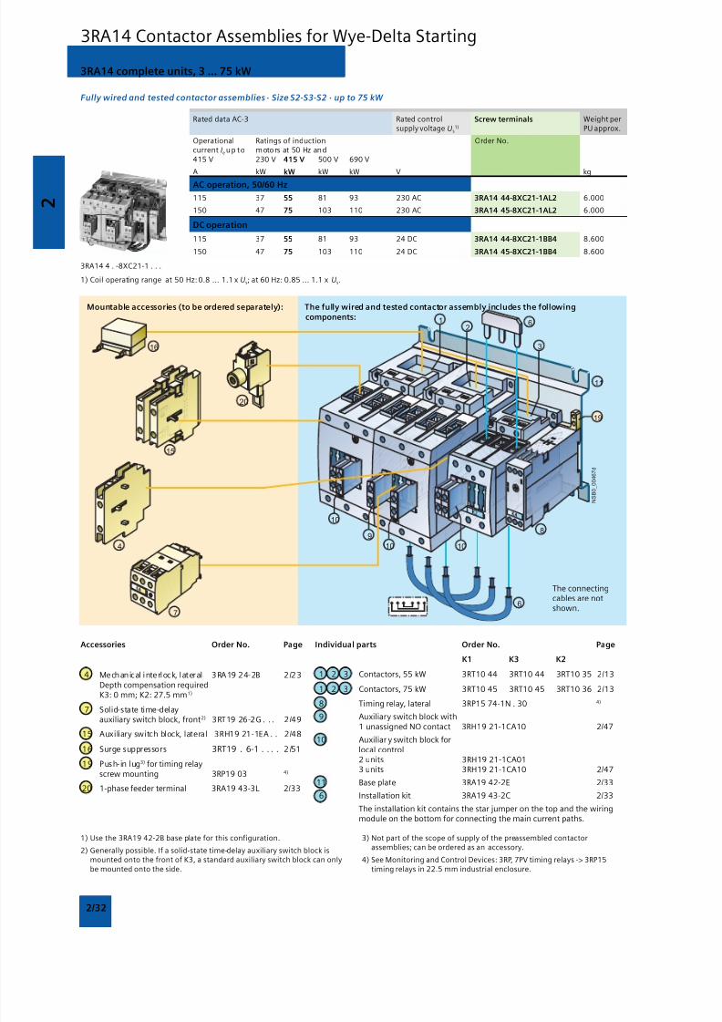
8/12/2019 SIRIUS Datasheet P-1
http://slidepdf.com/reader/full/sirius-datasheet-p-1 48/100
2
2/32
N S B 0_
0 0 4 6 7 d
8
2
1
3
6
7
10 10
6
11
9
10
16
15
4
19
20
Mountable accessories (to be ordered separately): The fully wired and tested contactor assembly includes the followingcomponents:
The connectingcables are notshown.
Fully wired and tested contactor assemblies · Size S2-S3-S2 · up to 75 kW
Rated data AC-3 Rated control Screw terminals Weight persupply voltage Us
1) PU approx.
Operational Ratings of induction Order No.current Ie up to motors at 50 Hz and415 V 230 V 415 V 500 V 690 V
A kW kW kW kW V kg
AC operation, 50/60 Hz
115 37 55 81 93 230 AC 3RA14 44-8XC21-1AL2 6.000
150 47 75 103 110 230 AC 3RA14 45-8XC21-1AL2 6.000
DC operation
115 37 55 81 93 24 DC 3RA14 44-8XC21-1BB4 8.600
150 47 75 103 110 24 DC 3RA14 45-8XC21-1BB4 8.600
1) Coil operating range at 50 Hz: 0.8 ... 1.1 x Us; at 60 Hz: 0.85 ... 1.1 x Us.
3RA14 4 . -8XC21-1 . . .
1) Use the 3RA19 42-2B base plate for this configuration.
2) Generally possible. If a solid-state time-delay auxiliary switch block ismounted onto the front of K3, a standard auxiliary switch block can onlybe mounted onto the side.
3) Not part of the scope of supply of the preassembled contactorassemblies; can be ordered as an accessory.
4) See Monitoring and Control Devices: 3RP, 7PV timing relays -> 3RP15timing relays in 22.5 mm industrial enclosure.
Accessories Order No. Page
4 Mechanical interlock, lateral 3RA19 24-2B 2/23Depth compensation requiredK3: 0 mm; K2: 27.5 mm 1)
7 Solid-state time-delay
auxiliary switch block, front2) 3RT19 26-2G . . . 2/49
15 Auxiliary switch block, lateral 3RH19 21-1EA . . 2/48
16 Surge suppressors 3RT19 . 6-1 . . . . 2 /51
19 Push-in lug3) for timing relayscrew mounting 3RP19 03 4)
20 1-phase feeder terminal 3RA19 43-3L 2/33
Individual parts Order No. Page
K1 K3 K2
1 2 3 Contactors, 55 kW 3RT10 44 3RT10 44 3RT10 35 2/13
1 2 3 Contactors, 75 kW 3RT10 45 3RT10 45 3RT10 36 2/13
8 Timing relay, lateral 3RP15 74-1N . 30 4)
9 Auxiliary switch block with1 unassigned NO contact 3RH19 21-1CA10 2/47
10 Auxiliar y switch block forlocal control2 units 3RH19 21-1CA013 units 3RH19 21-1CA10 2/47
11 Base plate 3RA19 42-2E 2/33
6 Installation kit 3RA19 43-2C 2/33
The installation kit contains the star jumper on the top and the wiringmodule on the bottom for connecting the main current paths.
3RA14 complete units, 3 ... 75 kW
3RA14 Contactor Assemblies for Wye-Delta Starting
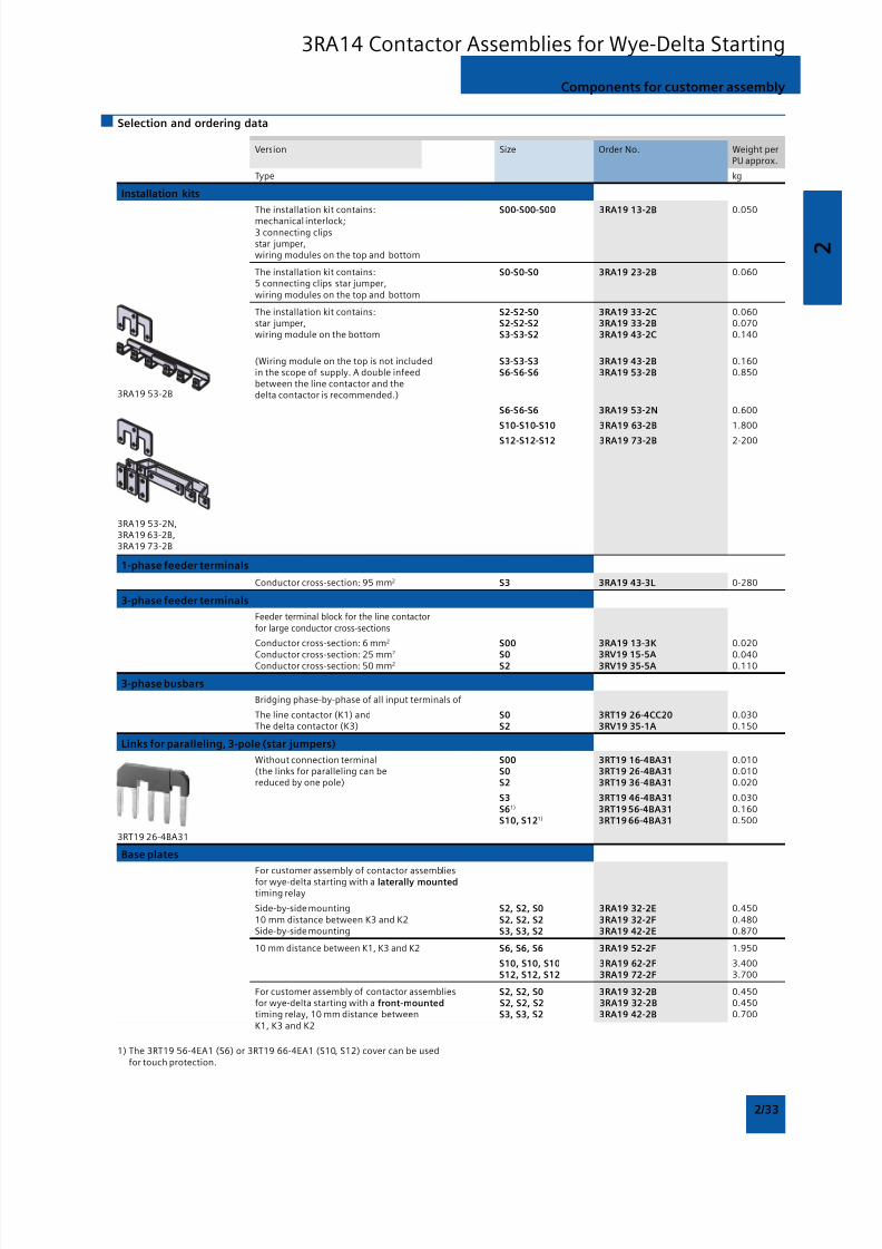
8/12/2019 SIRIUS Datasheet P-1
http://slidepdf.com/reader/full/sirius-datasheet-p-1 49/100
2
2/33
Version Size Order No. Weight perPU approx.
Type kg
Installation kits
The installation kit contains: S00-S00-S00 3RA19 13-2B 0.050
mechanical interlock;3 connecting clipsstar jumper,wiring modules on the top and bottom
The installation kit contains: S0-S0-S0 3RA19 23-2B 0.0605 connecting clips star jumper,wiring modules on the top and bottom
The installation kit contains: S2-S2-S0 3RA19 33-2C 0.060star jumper, S2-S2-S2 3RA19 33-2B 0.070wiring module on the bottom S3-S3-S2 3RA19 43-2C 0.140
(Wiring module on the top is not included S3-S3-S3 3RA19 43-2B 0.160in the scope of supply. A double infeed S6-S6-S6 3RA19 53-2B 0.850between the line contactor and thedelta contactor is recommended.)
S6-S6-S6 3RA19 53-2N 0.600
S10-S10-S10 3RA19 63-2B 1.800
S12-S12-S12 3RA19 73-2B 2-200
1-phase feeder terminals
Conductor cross-section: 95 mm2 S3 3RA19 43-3L 0-280
3-phase feeder terminals
Feeder terminal block for the line contactorfor large conductor cross-sections
Conductor cross-section: 6 mm2 S00 3RA19 13-3K 0.020
Conductor cross-section: 25 mm2
S0 3RV19 15-5A 0.040Conductor cross-section: 50 mm2 S2 3RV19 35-5A 0.110
3-phase busbars
Bridging phase-by-phase of all input terminals of
The line contactor (K1) and S0 3RT19 26-4CC20 0.030The delta contactor (K3) S2 3RV19 35-1A 0.150
Links for paralleling, 3-pole (star jumpers)
Without connection terminal S00 3RT19 16-4BA31 0.010(the links for paralleling can be S0 3RT19 26-4BA31 0.010reduced by one pole) S2 3RT19 36-4BA31 0.020
S3 3RT19 46-4BA31 0.030
S61) 3RT19 56-4BA31 0.160S10, S121) 3RT19 66-4BA31 0.500
Base plates
For customer assembly of contactor assembliesfor wye-delta starting with a laterally mountedtiming relay
Side-by-side mounting S2, S2, S0 3RA19 32-2E 0.45010 mm distance between K3 and K2 S2, S2, S2 3RA19 32-2F 0.480Side-by-side mounting S3, S3, S2 3RA19 42-2E 0.870
10 mm distance between K1, K3 and K2 S6, S6, S6 3RA19 52-2F 1.950
S10, S10, S10 3RA19 62-2F 3.400S12, S12, S12 3RA19 72-2F 3.700
For customer assembly of contactor assemblies S2, S2, S0 3RA19 32-2B 0.450for wye-delta starting with a front-mounted S2, S2, S2 3RA19 32-2B 0.450timing relay, 10 mm distance between S3, S3, S2 3RA19 42-2B 0.700K1, K3 and K2
Components for customer assembly
Selection and ordering data
3RA19 53-2B
3RA19 53-2N,3RA19 63-2B,3RA19 73-2B
3RT19 26-4BA31
1) The 3RT19 56-4EA1 (S6) or 3RT19 66-4EA1 (S10, S12) cover can be usedfor touch protection.
3RA14 Contactor Assemblies for Wye-Delta Starting

8/12/2019 SIRIUS Datasheet P-1
http://slidepdf.com/reader/full/sirius-datasheet-p-1 50/100
2
2/34
3-pole, 140 ... 690 A
3RT14 Contactors for Switching Resistive Loads (AC-1)
Overview
AC and DC operation (size S3)
UC operation (AC/DC) (sizes S6 to S12)
IEC 60947, EN 60947 (VDE 0660)
The contactors are suitable for use in any climate. They are
finger-safe according to EN 50274.
3RT14 contactors are used for switching resistive loads (AC-1) oras contactors, for example, for variable-speed operatingmechanisms that normally only have to carry the current.
The accessories for the 3RT10 contactors can also be used here.
For more detailed descriptions about the sizes S3 to S12,see 3RT10 Contactors, 3-pole, 3 to 250 kW.
Selection and ordering data
S ize Rated dat a AC-1, T u: 40 °C Rated control Screw terminals Weight persupply voltage PU approx.
Operational Ratings of AC loads Us Order No.current Ie up to (p.f. = 0.95) at690 V 230 V 400 V 500 V 690 V
A kW kW kW kW V kg
For screw and snap-on mounting onto 35 mm and 75 mm standard mounting rail
AC operation
S3 140 53 92 115 159 24 AC, 50/60 Hz 3RT14 46-1AC20 1.850110 AC, 50/60 Hz 3RT14 46-1AG00 1.850230 AC, 50/60 Hz 3RT14 46-1AL00 1.850400 AC, 50 Hz 3RT14 46-1AV00 1.850
DC operation · DC solenoid system
S3 140 53 92 115 159 24 DC 3RT14 46-1BB40 2.800110 DC 3RT14 46-1BF40 2.800220 DC 3RT14 46-1BM40 2.800
3RT14 46-1A..0
AC/DC operation (40 Hz to 60 Hz, DC) Auxiliary and control conductors: screw terminalsWithdrawable coilsIntegrated coil circuit (Varistor)
Main conductors: busbar connections
S ize Rated dat a AC-1, T u: 40 °C Auxiliary Rated control Screw terminals Weight percontacts supply voltage PU approx.
Operational Ratings of AC loads Version Us Order No.current Ie up to (p.f. = 0.95) at690 V 230 V 400 V 500 V 690 V NO NC
A kW kW kW kW V kg
Conventional operating mechanisms
S6 275 105 180 225 310 2 2 23 ... 26 3RT14 56-6AB36 3.3602 2 110 … 127 3RT14 56-6AF36 3.3602 2 220 … 240 3RT14 56-6AP36 3.360
S10 400 151 263 329 454 2 2 23 … 26 3RT14 66-6AB36 6.6002 2 110 … 127 3RT14 66-6AF36 6.6002 2 220 … 240 3RT14 66-6AP36 6.600
S12 690 261 454 568 783 2 2 23 … 26 3RT14 76-6AB36 10.5002 2 110 … 127 3RT14 76-6AF36 10.5002 2 220 … 240 3RT14 76-6AP36 10.500
3RT14 6.
For accessories, see page 2/46.For spare parts, see page 2/55.
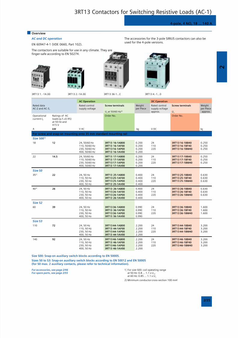
8/12/2019 SIRIUS Datasheet P-1
http://slidepdf.com/reader/full/sirius-datasheet-p-1 51/100
2
2/35
3RT13 1. -1A.00 3RT13 2.-1A.00
AC Operation DC Operation
Rated data Rated control Screw terminals Weight Rated control Screw terminals WeightAC-2 and AC-3, supply voltage per Piece supply voltage per Piece
Us at 50/60 Hz2) approx. Us approx.
Operational Ratings of AC Order No. Order No.
current Ie loads (p.f.=0.95)at 50 Hz and415 V
A kW V AC kg V DC kg
For screw and snap-on mounting onto 35 mm standard mounting rail
Size S001)
18 12 24, 50/60 Hz 3RT13 16-1AB00 0.200 24 3RT13 16-1BB40 0.250110, 50/60 Hz 3RT13 16-1AF00 0.200 110 3RT13 16-1BF40 0.250230, 50/60 Hz 3RT13 16-1AP00 0.200 220 3RT13 16-1BM40 0.250400, 50/60 Hz 3RT13 16-1AV00 0.200
22 14.5 24, 50/60 Hz 3RT13 17-1AB00 0.200 24 3RT13 17-1BB40 0.250110, 50/60 Hz 3RT13 17-1AF00 0.200 110 3RT13 17-1BF40 0.250230, 50/60 Hz 3RT13 17-1AP00 0.200 220 3RT13 17-1BM40 0.250400, 50/60 Hz 3RT13 17-1AV00 0.200
Size S0
352) 22 24, 50 Hz 3RT13 25-1AB00 0.400 24 3RT13 25-1BB40 0.630
110, 50 Hz 3RT13 25-1AF00 0.400 110 3RT13 25-1BF40 0.630230, 50 Hz 3RT13 25-1AP00 0.400 220 3RT13 25-1BM40 0.630400, 50 Hz 3RT13 25-1AV00 0.400
402) 26 24, 50 Hz 3RT13 26-1AB00 0.400 24 3RT13 26-1BB40 0.630110, 50 Hz 3RT13 26-1AF00 0.400 110 3RT13 26-1BF40 0.630230, 50 Hz 3RT13 26-1AP00 0.400 220 3RT13 26-1BM40 0.630400, 50 Hz 3RT13 26-1AV00 0.400
Size S2
60 39 24, 50 Hz 3RT13 36-1AB00 0.990 24 3RT13 36-1BB40 1.600110, 50 Hz 3RT13 36-1AF00 0.990 110 3RT13 36-1BF40 1.600230, 50 Hz 3RT13 36-1AP00 0.990 220 3RT13 36-1BM40 1.600400, 50 Hz 3RT13 36-1AV00 0.990
Size S3
110 72 24, 50 Hz 3RT13 44-1AB00 2.200 24 3RT13 44-1BB40 3.200110, 50 Hz 3RT13 44-1AF00 2.200 110 3RT13 44-1BF40 3.200230, 50 Hz 3RT13 44-1AP00 2.200 220 3RT13 44-1BM40 3.200400, 50 Hz 3RT13 44-1AV00 2.200
140 92 24, 50 Hz 3RT13 46-1AB00 2.200 24 3RT13 46-1BB40 3.200110, 50 Hz 3RT13 46-1AF00 2.200 110 3RT13 46-1BF40 3.200230, 50 Hz 3RT13 46-1AP00 2.200 220 3RT13 46-1BM40 3.200400, 50 Hz 3RT13 46-1AV00 2.200
Size S00: Snap-on auxiliary switch blocks according to EN 50005.
Sizes S0 to S3: Snap-on auxiliary switch blocks according to EN 50012 and EN 50005(for S0 max. 2 auxiliary contacts, please refer to technical information).
For accessories, see page 2/46For spare parts, see page 2/55
1) For size S00: coil operating rangeat 50 Hz: 0.8 ... 1.1 x U s,at 60 Hz: 0.85 ... 1.1 x U s
2) Minimum conductor cross-section 100 mm2
4-pole, 4 NO, 18 ... 140 A
Overview
AC and DC operation
EN 60947-4-1 (VDE 0660, Part 102).
The contactors are suitable for use in any climate. They arefinger-safe according to EN 50274.
The accessories for the 3-pole SIRIUS contactors can also beused for the 4-pole versions.
3RT13 36-1...0 3RT13 4.-1...0
3RT13 Contactors for Switching Resistive Loads (AC-1)
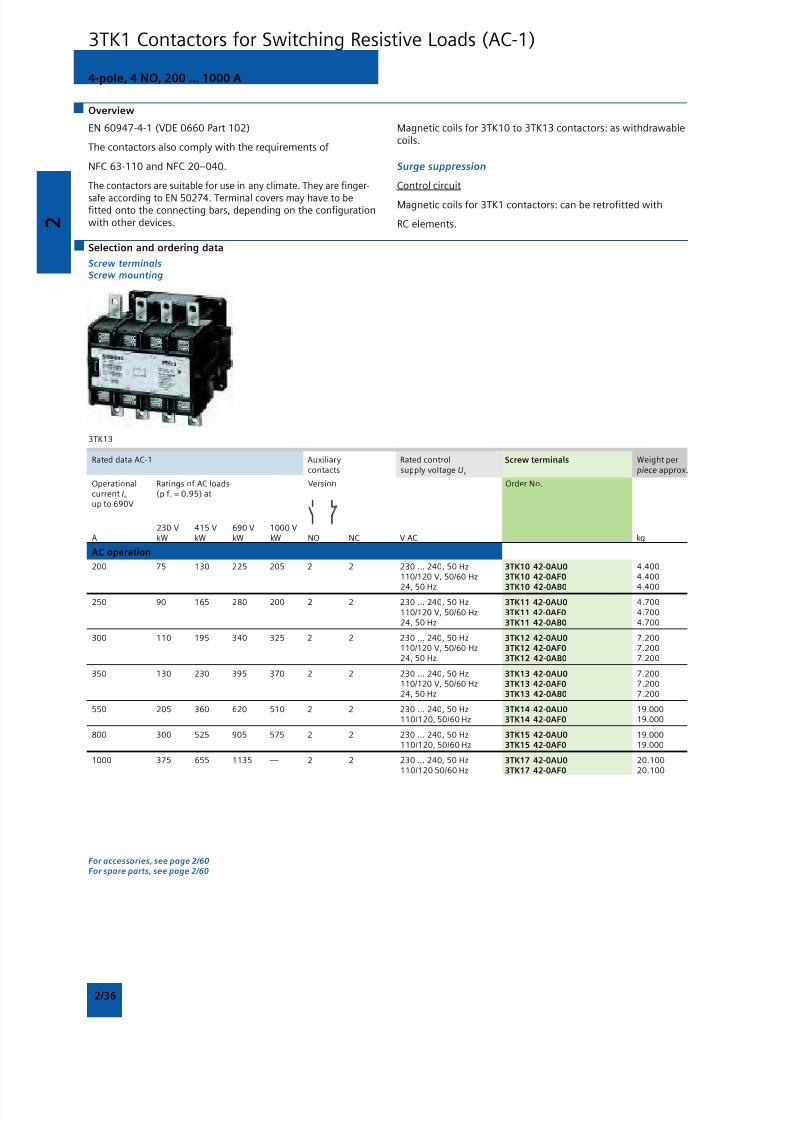
8/12/2019 SIRIUS Datasheet P-1
http://slidepdf.com/reader/full/sirius-datasheet-p-1 52/100
2
2/36
Overview
EN 60947-4-1 (VDE 0660 Part 102)
The contactors also comply with the requirements of
NFC 63-110 and NFC 20–040.
The contactors are suitable for use in any climate. They are finger-
safe according to EN 50274. Terminal covers may have to befitted onto the connecting bars, depending on the configurationwith other devices.
Magnetic coils for 3TK10 to 3TK13 contactors: as withdrawablecoils.
Surge suppression
Control circuit
Magnetic coils for 3TK1 contactors: can be retrofitted with
RC elements.
4-pole, 4 NO, 200 ... 1000 A
Selection and ordering data
Screw terminalsScrew mounting
3TK13
Rated data AC-1 Auxiliary Rated control Screw terminals Weight percontacts supply voltage Us piece approx.
Operational Ratings of AC loads Version Order No.current Ie (p f. = 0.95) atup to 690V
230 V 415 V 690 V 1000 VA kW kW kW kW NO NC V AC kg
AC operation
200 75 130 225 205 2 2 230 ... 240, 50 Hz 3TK10 42-0AU0 4.400110/120 V, 50/60 Hz 3TK10 42-0AF0 4.400
24, 50 Hz 3TK10 42-0AB0 4.400250 90 165 280 200 2 2 230 ... 240, 50 Hz 3TK11 42-0AU0 4.700
110/120 V, 50/60 Hz 3TK11 42-0AF0 4.70024, 50 Hz 3TK11 42-0AB0 4.700
300 110 195 340 325 2 2 230 ... 240, 50 Hz 3TK12 42-0AU0 7.200110/120 V, 50/60 Hz 3TK12 42-0AF0 7.20024, 50 Hz 3TK12 42-0AB0 7.200
350 130 230 395 370 2 2 230 ... 240, 50 Hz 3TK13 42-0AU0 7.200110/120 V, 50/60 Hz 3TK13 42-0AF0 7.20024, 50 Hz 3TK13 42-0AB0 7.200
550 205 360 620 510 2 2 230 ... 240, 50 Hz 3TK14 42-0AU0 19.000110/120, 50/60 Hz 3TK14 42-0AF0 19.000
800 300 525 905 575 2 2 230 ... 240, 50 Hz 3TK15 42-0AU0 19.000110/120, 50/60 Hz 3TK15 42-0AF0 19.000
1000 375 655 1135 — 2 2 230 ... 240, 50 Hz 3TK17 42-0AU0 20.100110/120 50/60 Hz 3TK17 42-0AF0 20.100
For accessories, see page 2/60For spare parts, see page 2/60
3TK1 Contactors for Switching Resistive Loads (AC-1)
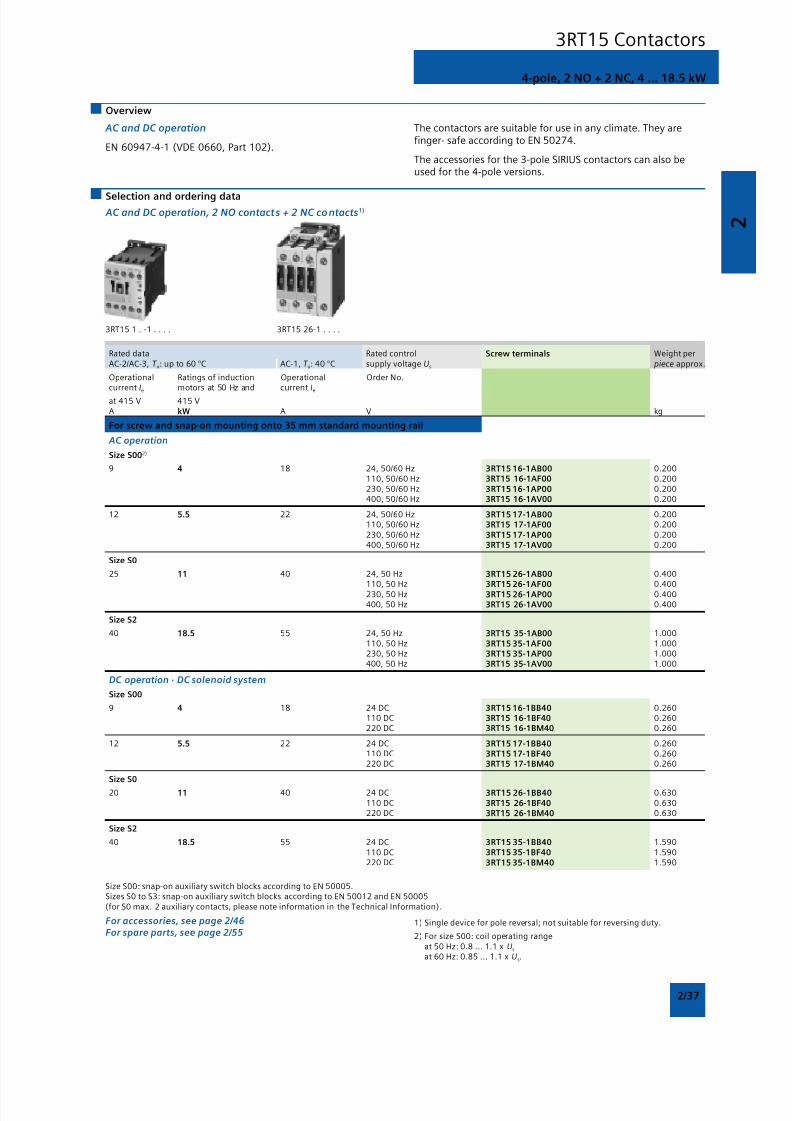
8/12/2019 SIRIUS Datasheet P-1
http://slidepdf.com/reader/full/sirius-datasheet-p-1 53/100
2
2/37
AC and DC operation
EN 60947-4-1 (VDE 0660, Part 102).
4-pole, 2 NO + 2 NC, 4 ... 18.5 kW
Overview
The contactors are suitable for use in any climate. They arefinger- safe according to EN 50274.
The accessories for the 3-pole SIRIUS contactors can also beused for the 4-pole versions.
Selection and ordering data AC and DC operation, 2 NO contacts + 2 NC contacts1)
3RT15 1 . -1 . . . . 3RT15 26-1 . . . .
Rated data Rated control Screw terminals Weight perAC-2/AC-3, T u: up to 60 °C AC-1, T u: 40 °C supply voltage Us piece approx.
Operational Ratings of induction Operational Order No.current I
emotors at 50 Hz and current I
e
at 415 V 415 VA kW A V kg
For screw and snap-on mounting onto 35 mm standard mounting rail
AC operation
Size S002)
9 4 18 24, 50/60 Hz 3RT15 16-1AB00 0.200110, 50/60 Hz 3RT15 16-1AF00 0.200230, 50/60 Hz 3RT15 16-1AP00 0.200400, 50/60 Hz 3RT15 16-1AV00 0.200
12 5.5 22 24, 50/60 Hz 3RT15 17-1AB00 0.200110, 50/60 Hz 3RT15 17-1AF00 0.200230, 50/60 Hz 3RT15 17-1AP00 0.200400, 50/60 Hz 3RT15 17-1AV00 0.200
Size S0
25 11 40 24, 50 Hz 3RT15 26-1AB00 0.400110, 50 Hz 3RT15 26-1AF00 0.400230, 50 Hz 3RT15 26-1AP00 0.400400, 50 Hz 3RT15 26-1AV00 0.400
Size S2
40 18.5 55 24, 50 Hz 3RT15 35-1AB00 1.000110, 50 Hz 3RT15 35-1AF00 1.000230, 50 Hz 3RT15 35-1AP00 1.000400, 50 Hz 3RT15 35-1AV00 1.000
DC operation · DC solenoid system
Size S00
9 4 18 24 DC 3RT15 16-1BB40 0.260110 DC 3RT15 16-1BF40 0.260220 DC 3RT15 16-1BM40 0.260
12 5.5 22 24 DC 3RT15 17-1BB40 0.260110 DC 3RT15 17-1BF40 0.260220 DC 3RT15 17-1BM40 0.260
Size S0
20 11 40 24 DC 3RT15 26-1BB40 0.630110 DC 3RT15 26-1BF40 0.630220 DC 3RT15 26-1BM40 0.630
Size S2
40 18.5 55 24 DC 3RT15 35-1BB40 1.590110 DC 3RT15 35-1BF40 1.590220 DC 3RT15 35-1BM40 1.590
Size S00: snap-on auxiliary switch blocks according to EN 50005.Sizes S0 to S3: snap-on auxiliary switch blocks according to EN 50012 and EN 50005(for S0 max. 2 auxiliary contacts, please note information in the Technical Information).
For accessories, see page 2/46For spare parts, see page 2/55
1) Single device for pole reversal; not suitable for reversing duty.
2) For size S00: coil operating rangeat 50 Hz: 0.8 ... 1.1 x Us
at 60 Hz: 0.85 ... 1.1 x Us.
3RT15 Contactors
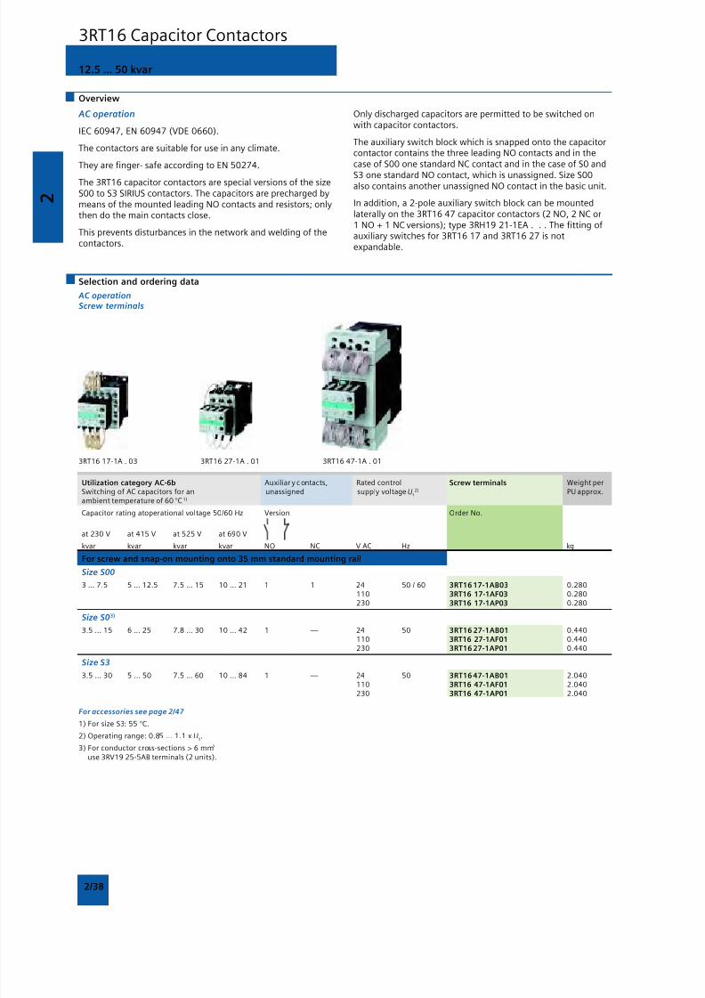
8/12/2019 SIRIUS Datasheet P-1
http://slidepdf.com/reader/full/sirius-datasheet-p-1 54/100
2
2/38
12.5 ... 50 kvar
AC operation
IEC 60947, EN 60947 (VDE 0660).
The contactors are suitable for use in any climate.
They are finger- safe according to EN 50274.
The 3RT16 capacitor contactors are special versions of the sizeS00 to S3 SIRIUS contactors. The capacitors are precharged bymeans of the mounted leading NO contacts and resistors; onlythen do the main contacts close.
This prevents disturbances in the network and welding of thecontactors.
Overview
Only discharged capacitors are permitted to be switched onwith capacitor contactors.
The auxiliary switch block which is snapped onto the capacitorcontactor contains the three leading NO contacts and in thecase of S00 one standard NC contact and in the case of S0 and
S3 one standard NO contact, which is unassigned. Size S00also contains another unassigned NO contact in the basic unit.
In addition, a 2-pole auxiliary switch block can be mountedlaterally on the 3RT16 47 capacitor contactors (2 NO, 2 NC or1 NO + 1 NC versions); type 3RH19 21-1EA . . . The fitting ofauxiliary switches for 3RT16 17 and 3RT16 27 is notexpandable.
Selection and ordering data
AC operationScrew terminals
3RT16 17-1A . 03 3RT16 27-1A . 01 3RT16 47-1A . 01
Utilization category AC-6b Auxiliar y c ontacts, Rated control Screw terminals Weight perSwitching of AC capacitors for an unassigned supply voltage Us
2) PU approx.ambient temperature of 60 °C1)
Capacitor rating atoperational voltage 50/60 Hz Version Order No.
at 230 V at 415 V at 525 V at 690 V
kvar kvar kvar kvar NO NC V AC Hz kg
For screw and snap-on mounting onto 35 mm standard mounting rail
Size S00
3 … 7.5 5 … 12.5 7.5 … 15 10 … 21 1 1 24 50 / 60 3RT16 17-1AB03 0.280110 3RT16 17-1AF03 0.280230 3RT16 17-1AP03 0.280
Size S03)
3.5 … 15 6 … 25 7.8 … 30 10 … 42 1 — 24 50 3RT16 27-1AB01 0.440110 3RT16 27-1AF01 0.440230 3RT16 27-1AP01 0.440
Size S3
3.5 … 30 5 … 50 7.5 … 60 10 … 84 1 — 24 50 3RT16 47-1AB01 2.040110 3RT16 47-1AF01 2.040230 3RT16 47-1AP01 2.040
For accessories see page 2/47
1) For size S3: 55 °C.
2) Operating range: 0.85 ... 1.1 x Us.
3) For conductor cross-sections > 6 mm2
use 3RV19 25-5AB terminals (2 units).
3RT16 Capacitor Contactors
8/12/2019 SIRIUS Datasheet P-1
http://slidepdf.com/reader/full/sirius-datasheet-p-1 55/100
2
2/39
Overview
1- and 2-pole, 32 ... 400 A
3TC4 and 3TC5
EN 60947-4-1 (VDE 0660 Part 102).
The contactors are finger-safe according to EN 50274.
Terminal covers may have to be fitted onto the connecting
bars, depending on the configuration with other devices.
The DC motor ratings given in the tables are applicable to theDC-3 and DC-5 utilization categories with two-pole switching
of the load or with the two conducting paths of the contactor
connected in series.
One contactor conducting path can switch full power up to220 V. The ratings for higher voltages are available on request.
Application
The contactors are suitable for switching and controlling DCmotors as well as all other DC circuits.
A version with an especially large actuating voltage is availablefor operation in electrically driven vehicles and in switchgearwith significant fluctuations in the operational voltage.
3TC Contactors for Switching DC Voltage
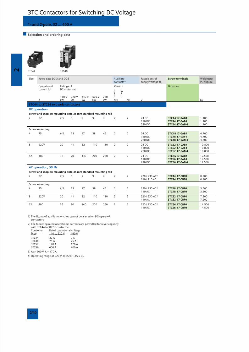
8/12/2019 SIRIUS Datasheet P-1
http://slidepdf.com/reader/full/sirius-datasheet-p-1 56/100
2
2/40
1- and 2-pole, 32 ... 400 A
Selection and ordering data
3TC44 3TC48
Size Rated data DC-3 and DC-5 Auxiliary Rated control Screw terminals Weight percontacts1) supply voltage Us PU approx.
Operational Ratings of Version Order No.current Ie
2) DC motors at
110 V 220 V 440 V 600 V 750A kW kW kW kW kW NO NC V kg
3TC44 to 3TC56 two-pole contactors
DC operation
Screw and snap-on mounting onto 35 mm standard mounting rail
2 32 2.5 5 9 9 4 2 2 24 DC 3TC44 17-0AB4 1.100110 DC 3TC44 17-0AF4 1.100220 DC 3TC44 17-0AM4 1.100
Screw mounting
4 75 6.5 13 27 38 45 2 2 24 DC 3TC48 17-0AB4 4.700110 DC 3TC48 17-0AF4 4.700220 DC 3TC48 17-0AM4 4.700
8 2203) 20 41 82 110 110 2 2 24 DC 3TC52 17-0AB4 10.800110 DC 3TC52 17-0AF4 10.800220 DC 3TC52 17-0AM4 10.800
12 400 35 70 140 200 250 2 2 24 DC 3TC56 17-0AB4 19.500110 DC 3TC56 17-0AF4 19.500220 DC 3TC56 17-0AM4 19.500
AC operation, 50 Hz
Screw and snap-on mounting onto 35 mm standard mounting rail
2 32 2.5 5 9 9 4 2 2 220 / 230 AC4) 3TC44 17-0BP0 0.700110 / 110 AC 3TC44 17-0BF0 0.700
Screw mounting4 75 6.5 13 27 38 45 2 2 220 / 230 AC4) 3TC48 17-0BP0 3.500
110 AC 3TC48 17-0BF0 3.500
8 2203) 20 41 82 110 110 2 2 220 / 230 AC4) 3TC52 17-0BP0 7.200110 AC 3TC52 17-0BF0 7.200
12 400 35 70 140 200 250 2 2 220 / 230 AC4) 3TC56 17-0BP0 14.500110 AC 3TC56 17-0BF0 14.500
1) The fitting of auxiliary switches cannot be altered on DC-operatedcontactors.
2) The following rated operational currents are permitted for reversing dutywith 3TC44 to 3TC56 contactors:Contactor Rated operational voltageType 110 V, 220 V 440 V
3TC44 32 A 7 A3TC48 75 A 75 A3TC52 170 A 170 A
3TC56 400 A 400 A
3) At > 600 V: Ie = 170 A.
4) Operating range at 220 V: 0.85 to 1.15 x Us.
3TC Contactors for Switching DC Voltage
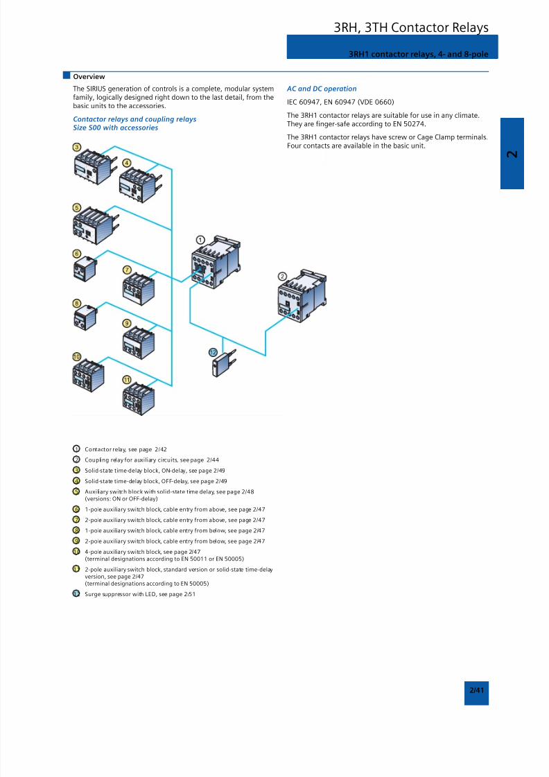
8/12/2019 SIRIUS Datasheet P-1
http://slidepdf.com/reader/full/sirius-datasheet-p-1 57/100
2
2/41
Overview
3RH1 contactor relays, 4- and 8-pole
The SIRIUS generation of controls is a complete, modular systemfamily, logically designed right down to the last detail, from thebasic units to the accessories.
Contactor relays and coupling relaysSize S00 with accessories
AC and DC operation
IEC 60947, EN 60947 (VDE 0660)
The 3RH1 contactor relays are suitable for use in any climate.They are finger-safe according to EN 50274.
The 3RH1 contactor relays have screw or Cage Clamp terminals.Four contacts are available in the basic unit.
1 Contactor relay, see page 2/42
2 Coupling relay for auxiliary circuits, see page 2/44
3 Solid-state time-delay block, ON-delay, see page 2/49
4 Solid-state time-delay block, OFF-delay, see page 2/49
5 Auxiliary switch block with solid-state time delay, see page 2/48(versions: ON or OFF-delay)
6 1-pole auxiliary switch block, cable entry from above, see page 2/47
7 2-pole auxiliary switch block, cable entry from above, see page 2/47
8 1-pole auxiliary switch block, cable entry from below, see page 2/47
9 2-pole auxiliary switch block, cable entry from below, see page 2/47
10 4-pole auxiliary switch block, see page 2/47(terminal designations according to EN 50011 or EN 50005)
11 2-pole auxiliary switch block, standard version or solid-state time-delayversion, see page 2/47(terminal designations according to EN 50005)
12 Surge suppressor with LED, see page 2/51
3RH, 3TH Contactor Relays
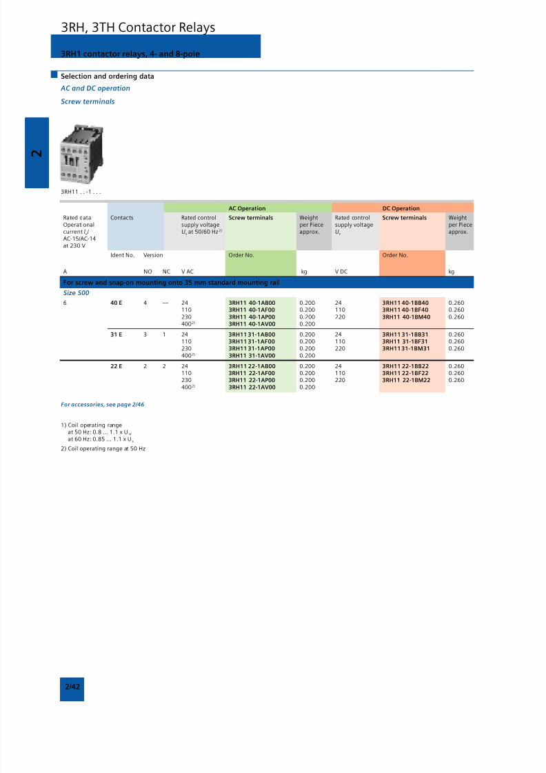
8/12/2019 SIRIUS Datasheet P-1
http://slidepdf.com/reader/full/sirius-datasheet-p-1 58/100
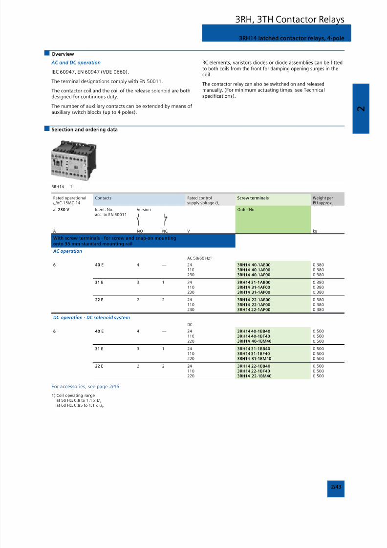
8/12/2019 SIRIUS Datasheet P-1
http://slidepdf.com/reader/full/sirius-datasheet-p-1 59/100
2
2/43
Overview
AC and DC operation
IEC 60947, EN 60947 (VDE 0660).
The terminal designations comply with EN 50011.
The contactor coil and the coil of the release solenoid are both
designed for continuous duty.
The number of auxiliary contacts can be extended by means ofauxiliary switch blocks (up to 4 poles).
RC elements, varistors diodes or diode assemblies can be fittedto both coils from the front for damping opening surges in thecoil.
The contactor relay can also be switched on and releasedmanually. (For minimum actuating times, see Technical
specifications).
3RH14 latched contactor relays, 4-pole
Selection and ordering data
3RH14 . -1 . . . .
Rated operational Contacts Rated control Screw terminals Weight perIe/AC-15/AC-14 supply voltage Us PU approx.
at 230 V Ident. No. Version Order No.acc. to EN 50011
A NO NC V kg
With screw terminals · for screw and snap-on mountingonto 35 mm standard mounting rail
AC operation
AC 50/60 Hz1)
6 40 E 4 — 24 3RH14 40-1AB00 0.380110 3RH14 40-1AF00 0.380230 3RH14 40-1AP00 0.380
31 E 3 1 24 3RH14 31-1AB00 0.380
110 3RH14 31-1AF00 0.380230 3RH14 31-1AP00 0.380
22 E 2 2 24 3RH14 22-1AB00 0.380110 3RH14 22-1AF00 0.380230 3RH14 22-1AP00 0.380
DC operation · DC solenoid system
DC
6 40 E 4 — 24 3RH14 40-1BB40 0.500110 3RH14 40-1BF40 0.500220 3RH14 40-1BM40 0.500
31 E 3 1 24 3RH14 31-1BB40 0.500110 3RH14 31-1BF40 0.500220 3RH14 31-1BM40 0.500
22 E 2 2 24 3RH14 22-1BB40 0.500110 3RH14 22-1BF40 0.500220 3RH14 22-1BM40 0.500
For accessories, see page 2/46
1) Coil operating rangeat 50 Hz: 0.8 to 1.1 x Us
at 60 Hz: 0.85 to 1.1 x Us.
3RH, 3TH Contactor Relays
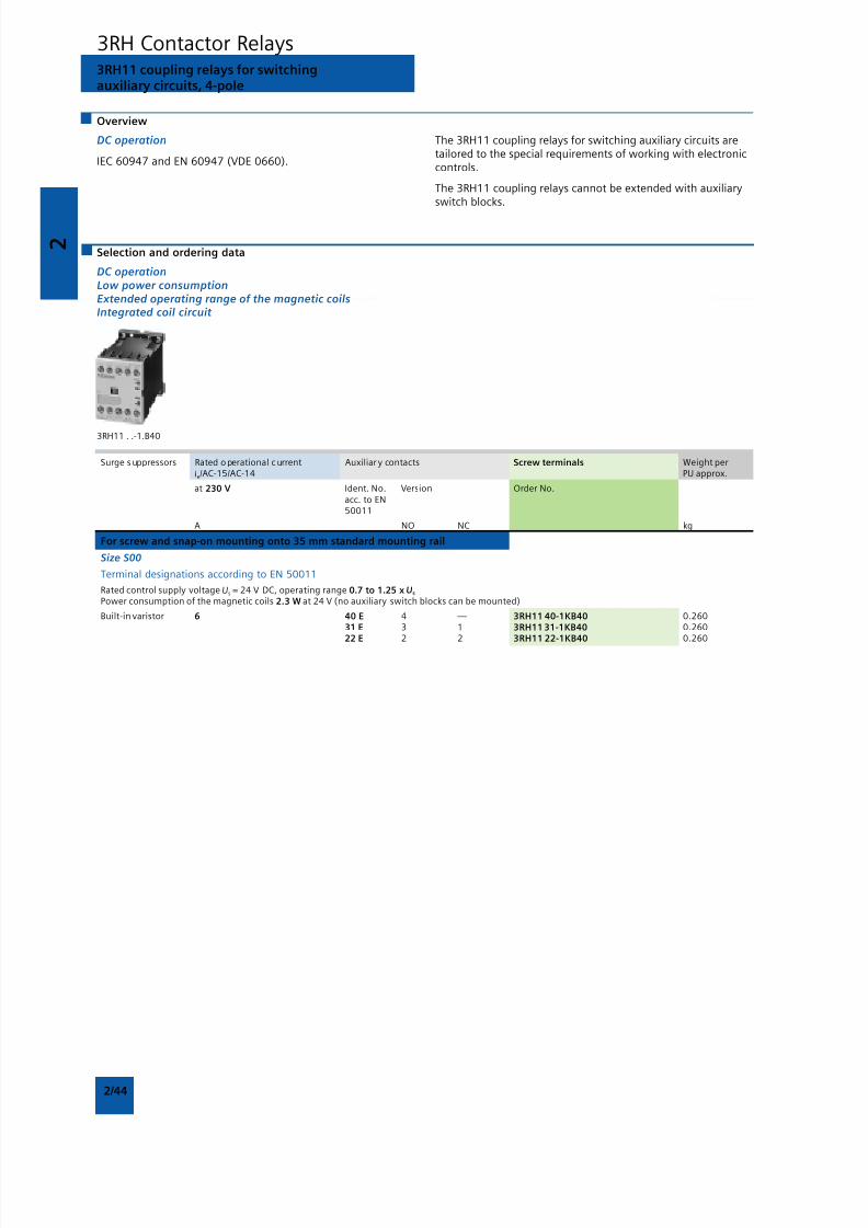
8/12/2019 SIRIUS Datasheet P-1
http://slidepdf.com/reader/full/sirius-datasheet-p-1 60/100
2
2/44
3RH11 coupling relays for switchingauxiliary circuits, 4-pole
Overview
DC operation
IEC 60947 and EN 60947 (VDE 0660).
The 3RH11 coupling relays for switching auxiliary circuits aretailored to the special requirements of working with electroniccontrols.
The 3RH11 coupling relays cannot be extended with auxiliaryswitch blocks.
Selection and ordering data
DC operationLow power consumptionExtended operating range of the magnetic coilsIntegrated coil circuit
3RH11 . .-1.B40
Surge s uppressors Rated o perational c urrent Auxiliar y contacts Screw terminals Weight perIe/AC-15/AC-14 PU approx.
at 230 V Ident. No. Version Order No.acc. to EN50011
A NO NC kg
For screw and snap-on mounting onto 35 mm standard mounting rail
Size S00
Terminal designations according to EN 50011
Rated control supply voltage Us = 24 V DC, operating range 0.7 to 1.25 x Us
Power consumption of the magnetic coils 2.3 W at 24 V (no auxiliary switch blocks can be mounted)
Built-in varistor 6 40 E 4 — 3RH11 40-1KB40 0.26031 E 3 1 3RH11 31-1KB40 0.26022 E 2 2 3RH11 22-1KB40 0.260
3RH Contactor Relays
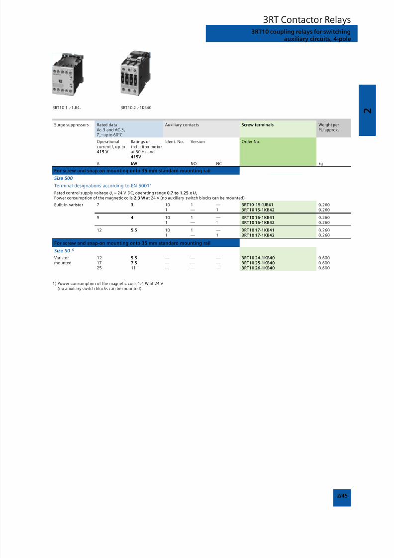
8/12/2019 SIRIUS Datasheet P-1
http://slidepdf.com/reader/full/sirius-datasheet-p-1 61/100
2
2/45
Surge suppressors Rated data Auxiliary contacts Screw terminals Weight perAc-3 and AC-3, PU approx.T u : upto 60°C
Operational Ratings of Ident. No. Version Order No.current Ie up to induction motor415 V at 50 Hz and
415V
A kW NO NC kg
For screw and snap-on mounting onto 35 mm standard mounting rail
Size S00
Terminal designations according to EN 50011
Rated control supply voltage Us = 24 V DC, operating range 0.7 to 1.25 x U
sPower consumption of the magnetic coils 2.3 W at 24 V (no auxiliary switch blocks can be mounted)
Built-in varistor 7 3 10 1 — 3RT10 15-1JB41 0.2601 — 1 3RT10 15-1KB42 0.260
9 4 10 1 — 3RT10 16-1KB41 0.2601 — 1 3RT10 16-1KB42 0.260
12 5.5 10 1 — 3RT10 17-1KB41 0.2601 — 1 3RT10 17-1KB42 0.260
For screw and snap-on mounting onto 35 mm standard mounting rail
Size S0 1)
Varistor 12 5.5 — — — 3RT10 24-1KB40 0.600mounted 17 7.5 — — — 3RT10 25-1KB40 0.600
25 11 — — — 3RT10 26-1KB40 0.600
1) Power consumption of the magnetic coils 1.4 W at 24 V(no auxiliary switch blocks can be mounted)
3RT10 coupling relays for switchingauxiliary circuits, 4-pole
3RT Contactor Relays
3RT10 1 .-1.B4. 3RT10 2 .-1KB40
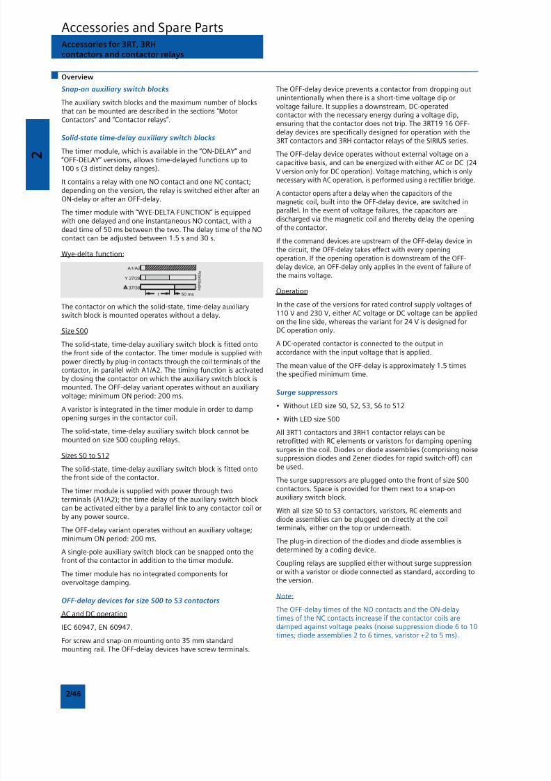
8/12/2019 SIRIUS Datasheet P-1
http://slidepdf.com/reader/full/sirius-datasheet-p-1 62/100
2
2/46
Accessories and Spare PartsAccessories for 3RT, 3RHcontactors and contactor relays
Snap-on auxiliary switch blocks
The auxiliary switch blocks and the maximum number of blocksthat can be mounted are described in the sections “MotorContactors” and “Contactor relays”.
Solid-state time-delay auxiliary switch blocks
The timer module, which is available in the “ON-DELAY” and“OFF-DELAY” versions, allows time-delayed functions up to100 s (3 distinct delay ranges).
It contains a relay with one NO contact and one NC contact;depending on the version, the relay is switched either after anON-delay or after an OFF-delay.
The timer module with “WYE-DELTA FUNCTION” is equippedwith one delayed and one instantaneous NO contact, with adead time of 50 ms between the two. The delay time of the NOcontact can be adjusted between 1.5 s and 30 s.
Wye-delta function:
Overview
The OFF-delay device prevents a contactor from dropping outunintentionally when there is a short-time voltage dip orvoltage failure. It supplies a downstream, DC-operatedcontactor with the necessary energy during a voltage dip,ensuring that the contactor does not trip. The 3RT19 16 OFF-delay devices are specifically designed for operation with the3RT contactors and 3RH contactor relays of the SIRIUS series.
The OFF-delay device operates without external voltage on acapacitive basis, and can be energized with either AC or DC (24V version only for DC operation). Voltage matching, which is onlynecessary with AC operation, is performed using a rectifier bridge.
A contactor opens after a delay when the capacitors of themagnetic coil, built into the OFF-delay device, are switched inparallel. In the event of voltage failures, the capacitors aredischarged via the magnetic coil and thereby delay the openingof the contactor.
If the command devices are upstream of the OFF-delay device inthe circuit, the OFF-delay takes effect with every openingoperation. If the opening operation is downstream of the OFF-delay device, an OFF-delay only applies in the event of failure of
the mains voltage.
Operation
In the case of the versions for rated control supply voltages of110 V and 230 V, either AC voltage or DC voltage can be appliedon the line side, whereas the variant for 24 V is designed forDC operation only.
A DC-operated contactor is connected to the output inaccordance with the input voltage that is applied.
The mean value of the OFF-delay is approximately 1.5 timesthe specified minimum time.
Surge suppressors
• Without LED size S0, S2, S3, S6 to S12
• With LED size S00
All 3RT1 contactors and 3RH1 contactor relays can beretrofitted with RC elements or varistors for damping openingsurges in the coil. Diodes or diode assemblies (comprising noisesuppression diodes and Zener diodes for rapid switch-off) canbe used.
The surge suppressors are plugged onto the front of size S00contactors. Space is provided for them next to a snap-onauxiliary switch block.
With all size S0 to S3 contactors, varistors, RC elements anddiode assemblies can be plugged on directly at the coilterminals, either on the top or underneath.
The plug-in direction of the diodes and diode assemblies is
determined by a coding device.
Coupling relays are supplied either without surge suppressionor with a varistor or diode connected as standard, according tothe version.
Note:
The OFF-delay times of the NO contacts and the ON-delaytimes of the NC contacts increase if the contactor coils aredamped against voltage peaks (noise suppression diode 6 to 10times; diode assemblies 2 to 6 times, varistor +2 to 5 ms).
The contactor on which the solid-state, time-delay auxiliaryswitch block is mounted operates without a delay.
Size S00
The solid-state, time-delay auxiliary switch block is fitted ontothe front side of the contactor. The timer module is supplied withpower directly by plug-in contacts through the coil terminals of thecontactor, in parallel with A1/A2. The timing function is activatedby closing the contactor on which the auxiliary switch block ismounted. The OFF-delay variant operates without an auxiliaryvoltage; minimum ON period: 200 ms.
A varistor is integrated in the timer module in order to dampopening surges in the contactor coil.
The solid-state, time-delay auxiliary switch block cannot bemounted on size S00 coupling relays.
Sizes S0 to S12
The solid-state, time-delay auxiliary switch block is fitted ontothe front side of the contactor.
The timer module is supplied with power through twoterminals (A1/A2); the time delay of the auxiliary switch blockcan be activated either by a parallel link to any contactor coil orby any power source.
The OFF-delay variant operates without an auxiliary voltage;minimum ON period: 200 ms.
A single-pole auxiliary switch block can be snapped onto thefront of the contactor in addition to the timer module.
The timer module has no integrated components forovervoltage damping.
OFF-delay devices for size S00 to S3 contactors
AC and DC operation
IEC 60947, EN 60947.
For screw and snap-on mounting onto 35 mm standardmounting rail. The OFF-delay devices have screw terminals.
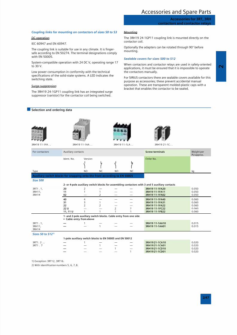
8/12/2019 SIRIUS Datasheet P-1
http://slidepdf.com/reader/full/sirius-datasheet-p-1 63/100
2
2/47
Accessories and Spare PartsAccessories for 3RT, 3RH
contactors and contactor relays
Coupling links for mounting on contactors of sizes S0 to S3
DC operation
IEC 60947 and EN 60947.
The coupling link is suitable for use in any climate. It is finger-safe according to EN 50274. The terminal designations complywith EN 50005.
System-compatible operation with 24 DC V, operating range 17to 30 V.
Low power consumption in conformity with the technicalspecifications of the solid-state systems. A LED indicates theswitching state.
Surge suppression
The 3RH19 24-1GP11 coupling link has an integrated surgesuppressor (varistor) for the contactor coil being switched.
Mounting
The 3RH19 24-1GP11 coupling link is mounted directly on thecontactor coil.
Optionally the adapters can be rotated through 90° beforemounting.
Sealable covers for sizes S00 to S12
When contactors and contactor relays are used in safety-orientedapplications, it must be ensured that it is impossible to operatethe contactors manually.
For SIRIUS contactors there are sealable covers available for thispurpose as accessories; these prevent accidental manualoperation. These are transparent molded-plastic caps with abracket that enables the contactor to be sealed.
Selection and ordering data
3RH19 11-1FA . . 3RH19 11-1AA . . 3RH19 11-1LA . . 3RH19 21-1C . .
For contactors Auxiliary contacts Screw terminals Weight perPU approx.
Ident. No. Version Order No.
Type NO NC NO NC kg
Auxiliary switch blocks for snapping onto the front according to EN 50005Size S00
2- or 4-pole auxiliary switch blocks for assembling contactors with 3 and 5 auxiliary contacts
3RT1 . 1, 20 2 — — — 3RH19 11-1FA20 0.0503RH11, 11 1 1 — — 3RH19 11-1FA11 0.0503RH14 02 — 2 — — 3RH19 11-1FA02 0.050
40 4 — — — 3RH19 11-1FA40 0.06031 3 1 — — 3RH19 11-1FA31 0.06022 2 2 — — 3RH19 11-1FA22 0.060
22 U — — 2 2 3RH19 11-1FC22 0.06011, 11 U 1 1 1 1 3RH19 11-1FB22 0.060
1- and 2-pole auxiliary switch blocks. Cable entry from one side• Cable entry from above
3RT1 . 1, — 1 — — — 3RH19 11-1AA10 0.0153RH11, — — 1 — — 3RH19 11-1AA01 0.0153RH14
Sizes S0 to S121)
1-pole auxiliary switch blocks to EN 50005 and EN 50012
3RT1. 2 ... — 1 — — — 3RH19 21-1CA10 0.0203RT1 . 7 — — 1 — — 3RH19 21-1CA01 0.020
— — — 1 — 3RH19 21-1CD10 0.020 — — — — 1 3RH19 21-1CD01 0.020
1) Exception: 3RT12, 3RT16.
2) With identification numbers 5, 6, 7, 8.
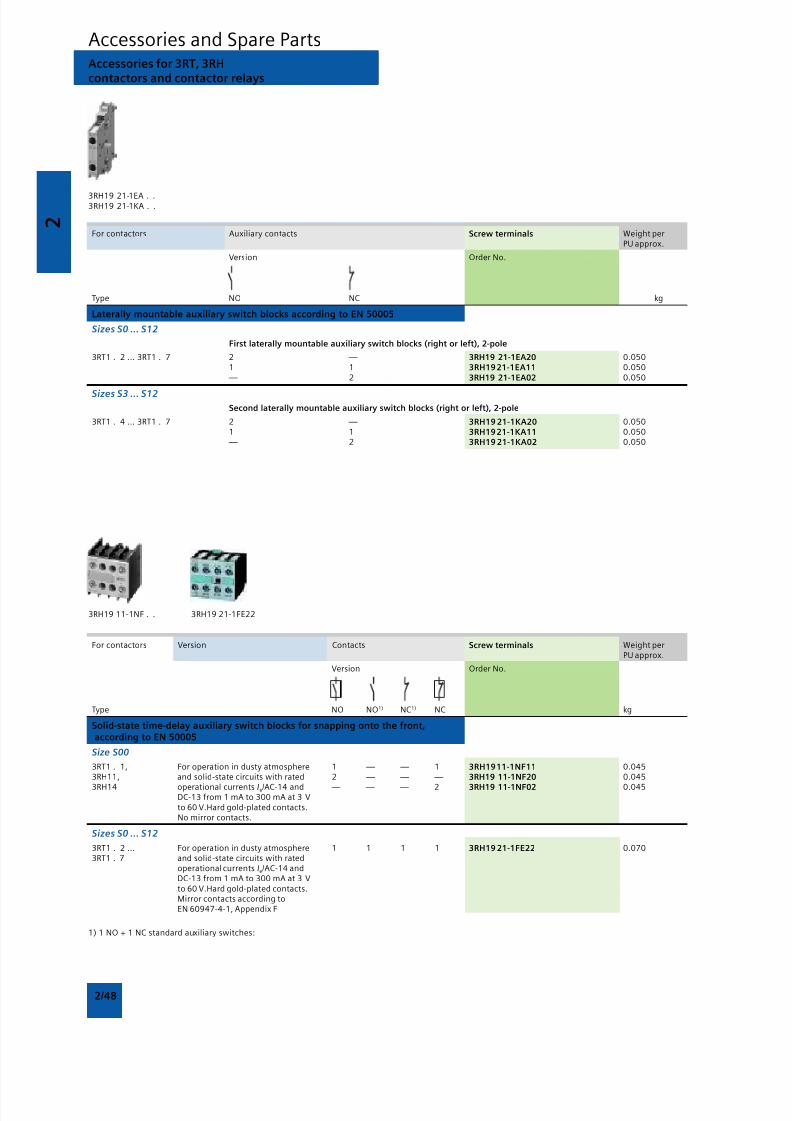
8/12/2019 SIRIUS Datasheet P-1
http://slidepdf.com/reader/full/sirius-datasheet-p-1 64/100
2
2/48
Accessories and Spare PartsAccessories for 3RT, 3RHcontactors and contactor relays
3RH19 21-1EA . .3RH19 21-1KA . .
For contactors Auxiliary contacts Screw terminals Weight perPU approx.
Version Order No.
Type NO NC kg
Laterally mountable auxiliary switch blocks according to EN 50005
Sizes S0 ... S12
First laterally mountable auxiliary switch blocks (right or left), 2-pole
3RT1 . 2 ... 3RT1 . 7 2 — 3RH19 21-1EA20 0.0501 1 3RH19 21-1EA11 0.050 — 2 3RH19 21-1EA02 0.050
Sizes S3 ... S12Second laterally mountable auxiliary switch blocks (right or left), 2-pole
3RT1 . 4 ... 3RT1 . 7 2 — 3RH19 21-1KA20 0.0501 1 3RH19 21-1KA11 0.050 — 2 3RH19 21-1KA02 0.050
3RH19 11-1NF . . 3RH19 21-1FE22
For contactors Version Contacts Screw terminals Weight perPU approx.
Version Order No.
Type NO NO1) NC1) NC kg
Solid-state time-delay auxiliary switch blocks for snapping onto the front, according to EN 50005
Size S00
3RT1 . 1, For operation in dusty atmosphere 1 — — 1 3RH19 11-1NF11 0.0453RH11, and solid-state circuits with rated 2 — — — 3RH19 11-1NF20 0.045
3RH14 operational currents Ie/AC-14 and — — — 2 3RH19 11-1NF02 0.045DC-13 from 1 mA to 300 mA at 3 Vto 60 V.Hard gold-plated contacts.No mirror contacts.
Sizes S0 ... S12
3RT1 . 2 ... For operation in dusty atmosphere 1 1 1 1 3RH19 21-1FE22 0.0703RT1 . 7 and solid-state circuits with rated
operational currents Ie/AC-14 andDC-13 from 1 mA to 300 mA at 3 Vto 60 V.Hard gold-plated contacts.Mirror contacts according toEN 60947-4-1, Appendix F
1) 1 NO + 1 NC standard auxiliary switches:
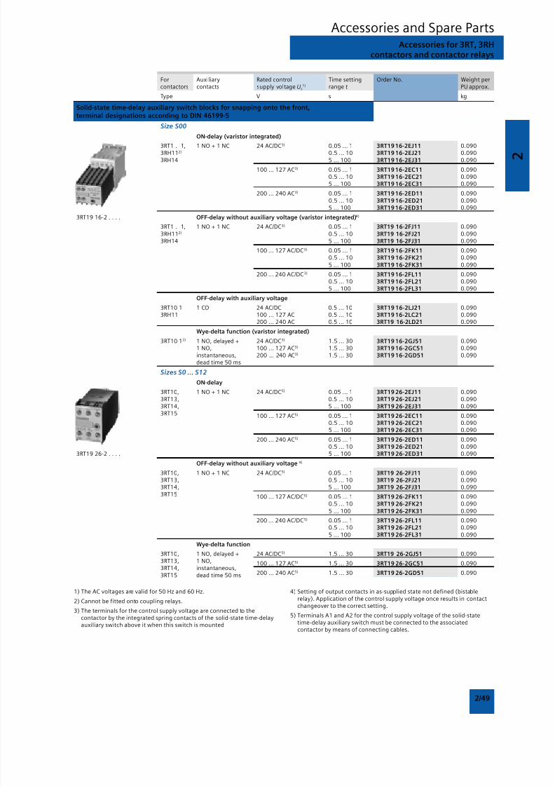
8/12/2019 SIRIUS Datasheet P-1
http://slidepdf.com/reader/full/sirius-datasheet-p-1 65/100
2
2/49
Accessories and Spare PartsAccessories for 3RT, 3RH
contactors and contactor relays
For Auxiliary Rated control Time setting Order No. Weight percontactors contacts supply voltage Us
1) range t PU approx.
Type V s kg
Solid-state time-delay auxiliary switch blocks for snapping onto the front,terminal designations according to DIN 46199-5
Size S00
ON-delay (varistor integrated)3RT1 . 1, 1 NO + 1 NC 24 AC/DC3) 0.05 ... 1 3RT19 16-2EJ11 0.0903RH112) 0.5 ... 10 3RT19 16-2EJ21 0.0903RH14 5 ... 100 3RT19 16-2EJ31 0.090
100 ... 127 AC3) 0.05 ... 1 3RT19 16-2EC11 0.0900.5 ... 10 3RT19 16-2EC21 0.0905 ... 100 3RT19 16-2EC31 0.090
200 ... 240 AC3) 0.05 ... 1 3RT19 16-2ED11 0.0900.5 ... 10 3RT19 16-2ED21 0.0905 ... 100 3RT19 16-2ED31 0.090
3RT19 16-2 . . . . OFF-delay without auxiliary voltage (varistor integrated)4)
3RT1 . 1, 1 NO + 1 NC 24 AC/DC3) 0.05 ... 1 3RT19 16-2FJ11 0.0903RH112) 0.5 ... 10 3RT19 16-2FJ21 0.0903RH14 5 ... 100 3RT19 16-2FJ31 0.090
100 ... 127 AC/DC3) 0.05 ... 1 3RT19 16-2FK11 0.0900.5 ... 10 3RT19 16-2FK21 0.0905 ... 100 3RT19 16-2FK31 0.090
200 ... 240 AC/DC3)
0.05 ... 1 3RT19 16-2FL11 0.0900.5 ... 10 3RT19 16-2FL21 0.0905 ... 100 3RT19 16-2FL31 0.090
OFF-delay with auxiliary voltage
3RT10 1 1 CO 24 AC/DC 0.5 ... 10 3RT19 16-2LJ21 0.0903RH11 100 ... 127 AC 0.5 ... 10 3RT19 16-2LC21 0.090
200 ... 240 AC 0.5 ... 10 3RT19 16-2LD21 0.090
Wye-delta function (varistor integrated)
3RT10 12) 1 NO, delayed + 24 AC/DC3) 1.5 ... 30 3RT19 16-2GJ51 0.0901 NO, 100 ... 127 AC3) 1.5 ... 30 3RT19 16-2GC51 0.090instantaneous, 200 ... 240 AC3) 1.5 ... 30 3RT19 16-2GD51 0.090dead time 50 ms
Sizes S0 ... S12
ON-delay
3RT10, 1 NO + 1 NC 24 AC/DC5) 0.05 ... 1 3RT19 26-2EJ11 0.0903RT13, 0.5 ... 10 3RT19 26-2EJ21 0.0903RT14, 5 ... 100 3RT19 26-2EJ31 0.090
3RT15 100 ... 127 AC5) 0.05 ... 1 3RT19 26-2EC11 0.0900.5 ... 10 3RT19 26-2EC21 0.0905 ... 100 3RT19 26-2EC31 0.090
200 ... 240 AC5) 0.05 ... 1 3RT19 26-2ED11 0.0900.5 ... 10 3RT19 26-2ED21 0.090
3RT19 26-2 . . . . 5 ... 100 3RT19 26-2ED31 0.090
OFF-delay without auxiliary voltage 4)
3RT10, 1 NO + 1 NC 24 AC/DC5) 0.05 ... 1 3RT19 26-2FJ11 0.0903RT13, 0.5 ... 10 3RT19 26-2FJ21 0.0903RT14, 5 ... 100 3RT19 26-2FJ31 0.0903RT15 100 ... 127 AC/DC5) 0.05 ... 1 3RT19 26-2FK11 0.090
0.5 ... 10 3RT19 26-2FK21 0.0905 ... 100 3RT19 26-2FK31 0.090
200 ... 240 AC/DC5) 0.05 ... 1 3RT19 26-2FL11 0.0900.5 ... 10 3RT19 26-2FL21 0.0905 ... 100 3RT19 26-2FL31 0.090
Wye-delta function
3RT10, 1 NO, delayed + 24 AC/DC5) 1.5 ... 30 3RT19 26-2GJ51 0.0903RT13, 1 NO, 100 ... 127 AC5) 1.5 ... 30 3RT19 26-2GC51 0.0903RT14, instantaneous,
200 ... 240 AC5) 1.5 ... 30 3RT19 26-2GD51 0.0903RT15 dead time 50 ms
1) The AC voltages are valid for 50 Hz and 60 Hz.
2) Cannot be fitted onto coupling relays.
3) The terminals for the control supply voltage are connected to thecontactor by the integrated spring contacts of the solid-state time-delayauxiliary switch above it when this switch is mounted
4) Setting of output contacts in as-supplied state not defined (bistablerelay). Application of the control supply voltage once results in contactchangeover to the correct setting.
5) Terminals A1 and A2 for the control supply voltage of the solid-statetime-delay auxiliary switch must be connected to the associatedcontactor by means of connecting cables.

8/12/2019 SIRIUS Datasheet P-1
http://slidepdf.com/reader/full/sirius-datasheet-p-1 66/100
2
2/50
For Rated control Time setting Order No. Weight percontactors supply voltage Us range t PU approx.
Type V s kg
Solid-state time-delay blocks with semiconductor output
Size S00
For mounting onto the front side of contactors
• ON-delay (varistor integrated)3RT1. 1, 24 ... 66 AC/DC 0.05 ... 1 3RT19 16-2CG11 0.0503RH111) 0.5 ... 10 3RT19 16-2CG21 0.0503RH14 5 ... 100 3RT19 16-2CG31 0.050
90 ... 240 AC/DC 0.05 ... 1 3RT19 16-2CH11 0.0500.5 ... 10 3RT19 16-2CH21 0.050
3RT19 16-2C. . . 5 ... 100 3RT19 16-2CH31 0.050
• OFF-delay with auxiliary voltage (varistor integrated)
3RT1. 1, 24 ... 66 AC/DC 0.05 ... 1 3RT19 16-2DG11 0.0603RH111) 0.5 ... 10 3RT19 16-2DG21 0.0603RH14 5 ... 100 3RT19 16-2DG31 0.060
90 ... 240 AC/DC 0.05 ... 1 3RT19 16-2DH11 0.0600.5 ... 10 3RT19 16-2DH21 0.060
3RT19 16-2D. . . 5 ... 100 3RT19 16-2DH31 0.060
Sizes S0 ... S3
For mounting onto coil terminals on top of the contactors• ON-delay (varistor integrated)
3RT10 2, 3RT10 3, 24 ... 66 AC/DC 0.05 ... 1 3RT19 26-2CG11 0.0503RT10 4, 3RT131) 0.5 ... 10 3RT19 26-2CG21 0.0503RT15 5 ... 100 3RT19 26-2CG31 0.050
90 ... 240 AC/DC 0.05 ... 1 3RT19 26-2CH11 0.0500.5 ... 10 3RT19 26-2CH21 0.050
3RT19 26-2C... 5 ... 100 3RT19 26-2CH31 0.050
• OFF-delay with auxiliary voltage (varistor integrated)
3RT10 2, 3RT10 3, 24 ... 66 AC/DC 0.05 ... 1 3RT19 26-2DG11 0.0503RT10 4, 3RT131) 0.5 ... 10 3RT19 26-2DG21 0.0503RT15 5 ... 100 3RT19 26-2DG31 0.050
90 ... 240 AC/DC 0.05 ... 1 3RT19 26-2DH11 0.0500.5 ... 10 3RT19 26-2DH21 0.050
3RT19 26-2D... 5 ... 100 3RT19 26-2DH31 0.050
OFF-delay devices
3RT1. 1, 3RT1. 2, 110 AC/DC 3RT19 16-2BK01 0.1503RH1. ..-1BF40
3RT1. 1, 3RT1. 2, 220/230 AC/DC 3RT19 16-2BL01 0.1503RH1. ..-1BM40
3RT1. 1 ... 3RT1. 4, 24 DC 3RT19 16-2BE01 0.1503RH1. ..-1BB40
3RT19 16-2B.01
Pneumatic delay blocks, terminal designation according to EN 50005
3RT1. 2 For mounting onto the front side of size S0 contactors2)3)
Auxiliary contacts 1 NO and 1 NC
• ON-delay
0.1 ... 30 3RT19 26-2PA01 0.0801 ... 60 3RT19 26-2PA11 0.080
3RT19 26-2P... • OFF-delay
0.1 ... 30 3RT19 26-2PR01 0.0801 ... 60 3RT19 26-2PR11 0.080
Mechanical latching blocks
Sizes S0 and S2
For mounting on 1 contactor,contactor remains in the energized state even after a voltage failure
3RT1. 2, 24 AC/DC 3RT19 26-3AB31 0.1303RT1. 3 110 AC/DC 3RT19 26-3AF31 0.130
230 AC/DC 3RT19 26-3AP31 0.130
3RT19 26-3A.31
Accessories and Spare PartsAccessories for 3RT, 3RHcontactors and contactor relays
1) Not to be used for 3RT10 4. and 3RT13 4. contactors with Us ≤ 42 V.
2) In addition to these, no other auxiliary contacts are permitted.
3) Versions according to DIN VDE 0116 on request.
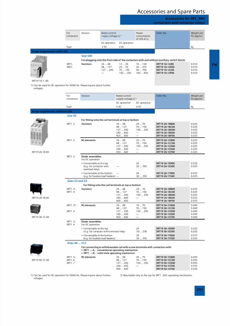
8/12/2019 SIRIUS Datasheet P-1
http://slidepdf.com/reader/full/sirius-datasheet-p-1 67/100
2
2/51
Accessories and Spare PartsAccessories for 3RT, 3RH
contactors and contactor relays
For Version Rated control Power Order No. Weight percontactors supply voltage Us
1) consumption PU approx.of LED at Us
AC operation DC operation
Type V AC V DC kg
Surge suppressors with LED
Size S00For plugging onto the front side of the contactors with and without auxiliary switch blocks
3RT1, Varistors 24 ... 48 12 ... 24 10 ... 120 3RT19 16-1JJ00 0.0103RH1. 48 ... 127 24 ... 70 20 ... 470 3RT19 16-1JK00 0.010
127 ... 240 70 ... 150 50 ... 700 3RT19 16-1JL00 0.010 — 150 ... 250 160 ... 950 3RT19 16-1JP00 0.010
3RT19 16-1..00
1) Can be used for AC operation for 50/60 Hz. Please inquire about furthervoltages.
For Version Rated control Order No. Weight percontactors supply voltage Us
1) PU approx.
AC opera tion DC opera tion
Type V AC V DC kg
Surge suppressors without LED
Size S0
For fitting onto the coil terminals at top or bottom
3RT1. 2 Varistors 24 ... 48 24 ... 70 3RT19 26-1BB00 0.02548 ... 127 70 ... 150 3RT19 26-1BC00 0.025127 ... 240 150 ... 250 3RT19 26-1BD00 0.025240 ... 400 — 3RT19 26-1BE00 0.025400 ... 600 — 3RT19 26-1BF00 0.025
3RT1. 2 RC elements 24 ... 48 24 ... 70 3RT19 26-1CB00 0.02548 ... 127 70 ... 150 3RT19 26-1CC00 0.025127 ... 240 150 ... 250 3RT19 26-1CD00 0.025240 ... 400 — 3RT19 26-1CE00 0.025
3RT19 26-1B.00 400 ... 600 — 3RT19 26-1CF00 0.025
3RT1. 2 Diode assembliesFor DC operation
• Connectable at the top — 24 3RT19 26-1ER00 0.025(e.g. for contactor with — 30 ... 250 3RT19 26-1ES00 0.025overload relay)
• Connectable at the bottom — 24 3RT19 26-1TR00 0.025(e.g. for fuseless load feeders) — 30 ... 250 3RT19 26-1TS00 0.025
Sizes S2 and S3
For fitting onto the coil terminals at top or bottom
3RT1. 3, Varistors 24 ... 48 24 ... 70 3RT19 26-1BB00 0.0253RT1. 4 48 ... 127 70 ... 150 3RT19 26-1BC00 0.025
127 ... 240 150 ... 250 3RT19 26-1BD00 0.0253RT19 26-1B.00 240 ... 400 — 3RT19 26-1BE00 0.025
400 ... 600 3RT19 26-1BF00 0.025
3RT1. 33), RC elements 24 ... 48 24 ... 70 3RT19 36-1CB00 0.04048 ... 127 70 ... 150 3RT19 36-1CC00 0.040
3RT1. 4 127 ... 240 150 ... 250 3RT19 36-1CD00 0.040240 ... 400 — 3RT19 36-1CE00 0.040
3RT19 36-1C.00 400 ... 600 — 3RT19 36-1CF00 0.040
3RT1. 3, Diode assemblies3RT1. 4 For DC operation
• Connectable at the top 24 3RT19 36-1ER00 0.025(e.g. for contactor with overload relay) 30 . .. 250 3RT19 36-1ES00 0.025
• Connectable at the bottom 24 3RT19 36-1TR00 0.025(e.g. for fuseless load feeders) 30 ... 250 3RT19 36-1TS00 0.025
Sizes S6 ... S12
For connecting to withdrawable coil with screw terminals with contactors with• 3RT1 ..-.A... conventional operating mechanism• 3RT1 ..-.N... solid-state operating mechanism
3RT1. 5, RC elements 24 ... 48 24 ... 70 3RT19 56-1CB00 0.0353RT19 56-1C.00 3RT1. 6, 48 ... 127 70 ... 150 3RT19 56-1CC00 0.035
3RT1. 7 127 ... 240 150 ... 250 3RT19 56-1CD00 0.035240 ... 400 — 3RT19 56-1CE00 0.035400 ... 600 3RT19 56-1CF00 0.035
1) Can be used for AC operation for 50/60 Hz. Please inquire about furthervoltages.
3) Mountable only at the top for 3RT1. 3/AC operating mechanism.
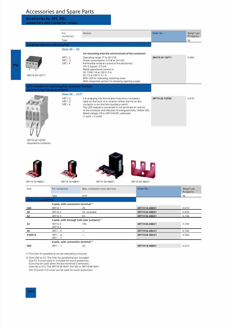
8/12/2019 SIRIUS Datasheet P-1
http://slidepdf.com/reader/full/sirius-datasheet-p-1 68/100
2
2/52
3RT19 16-4BB31 3RT19 16-4BB41 3RT19 36-4BB31 3RT19 56-4BA31
Size For contactors Max. conductor cross-sections Order No. Weight perPU approx.
Type mm2 kg
Links for paralleling
3-pole, with connection terminal1)2)
S00 3RT10 1 25 3RT19 16-4BB31 0.015
S0 3RT10 2 35, stranded 3RT19 26-4BB31 0.020
S2 3RT10 3 95 3RT19 36-4BB31 0.100
3-pole, with through hole (star jumpers)1)2)
S3 3RT10 4 185 3RT19 46-4BB31 0.2003RT14 4
S6 3RT1 . 5 — 3RT19 56-4BA31 0.160
S10/S12 3RT1 . 6, — 3RT19 66-4BA31 0.5003RT1 . 7
4-pole, with connection terminal1)2)
S00 3RT1 . 1 25 3RT19 16-4BB41 0.015
1) The links for paralleling can be reduced by one pole.
2) Sizes S00 to S2: The links for paralleling are insulated.Size S3: A cover plate is included for touch protection.(Can only be used when the box terminal is removed.)Sizes S6 to S12: The 3RT19 56-4EA1 (for S6) or 3RT19 66-4EA1
(for S10 and S12) cover can be used for touch protection.
Accessories and Spare PartsAccessories for 3RT, 3RHcontactors and contactor relays
For Version Order No. Weight percontactors PU approx.
Type kg
Coupling links for control by PLC
Sizes S0 ... S3
For mounting onto the coil terminals of the contactors
3RT1. 2, Operating range 17 to 30 V DC 3RH19 24-1GP11 0.0603RT1. 3, Power consumption: 0.5 W at 24 V DC3RT1. 4 Permissible residual current of the e lectronics
(for 0 signal): 2.5 mARated operational current Ie:AC-15/AC-14 at 230 V: 3 A,
3RH19 24-1GP11 DC-13 at 230 V: 0.1 AWith LED for indicating switching state.With integrated varistor for damping opening surges.
LED modules for indicating the contactor function(also for Cage Clamp terminals)
Sizes S0 ... S121)
3RT1. 2, For snapping into the locat ion hole of an inscr ipt ion 3RT19 26-1QT00 0.0103RT1. 3, label on the front of a contactor either direct ly on the3 RT1. 4 contactor or on the f ront auxil iary switch .
The LED module is connected to coil terminals A1 and A2of the contactor and indicates its energized state. Yellow LED.Rated voltage: 24 to 240 V AC/DC, polarized.(1 pack = 5 units)
3RT19 26-1QT00mounted to contactor
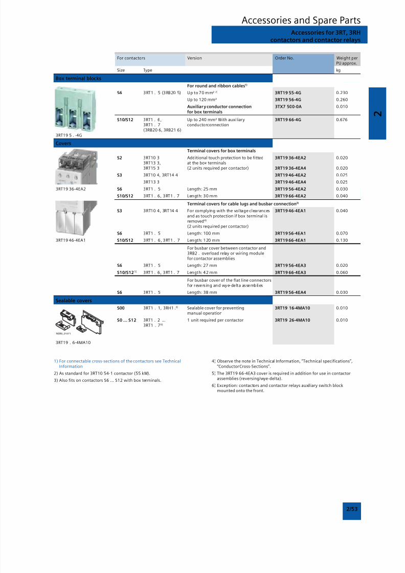
8/12/2019 SIRIUS Datasheet P-1
http://slidepdf.com/reader/full/sirius-datasheet-p-1 69/100
2
2/53
Accessories and Spare PartsAccessories for 3RT, 3RH
contactors and contactor relays
For contactors Version Order No. Weight perPU approx.
Size Type kg
Box terminal blocks
For round and ribbon cables1)
S6 3RT1 . 5 (3RB20 5) Up to 70 mm² 2) 3RT19 55-4G 0.230
Up to 120 mm² 3RT19 56-4G 0.260Auxiliar y conductor connection 3TX7 500-0A 0.010
for box terminals
S10/S12 3RT1 . 6, Up to 240 mm² With auxiliary 3RT19 66-4G 0.6763RT1 . 7 conductorconnection(3RB20 6, 3RB21 6)
3RT19 5 . -4G
Covers
Terminal covers for box terminals
S2 3RT10 3 Additional touch protection to be fitted 3RT19 36-4EA2 0.0203RT13 3, at the box terminals3RT15 3 (2 units required per contactor) 3RT19 36-4EA4 0.020
S3 3RT10 4, 3RT14 4 3RT19 46-4EA2 0.025
3RT13 3 3RT19 46-4EA4 0.025
3RT19 36-4EA2 S6 3RT1 . 5 Length: 25 mm 3RT19 56-4EA2 0.030
S10/S12 3RT1 . 6, 3RT1 . 7 Length: 30 mm 3RT19 66-4EA2 0.040
Terminal covers for cable lugs and busbar connection3)
S3 3RT10 4, 3RT14 4 For complying with the voltage clearances 3RT19 46-4EA1 0.040and as touch protection if box terminal isremoved4)
(2 units required per contactor)
S6 3RT1 . 5 Length: 100 mm 3RT19 56-4EA1 0.070
3RT19 46-4EA1 S10/S12 3RT1 . 6, 3RT1 . 7 Length: 120 mm 3RT19 66-4EA1 0.130
For busbar cover between contactor and3RB2 . overload relay or wiring modulefor contactor assemblies
S6 3RT1 . 5 Length: 27 mm 3RT19 56-4EA3 0.020
S10/S12 5) 3RT1 . 6, 3RT1 . 7 Length: 42 mm 3RT19 66-4EA3 0.060
For busbar cover of the flat line connectorsfor reversing and wye-delta assemblies
S6 3RT1 . 5 Length: 38 mm 3RT19 56-4EA4 0.030
Sealable coversS00 3RT1 . 1, 3RH1 .6) Sealable cover for preventing 3RT19 16-4MA10 0.010
manual operation
S0 ... S12 3RT1 . 2 ... 1 unit required per contactor 3RT19 26-4MA10 0.0103RT1 . 76)
3RT19 . 6-4MA10
1) For connectable cross-sections of the contactors see TechnicalInformation
2) As standard for 3RT10 54-1 contactor (55 kW).
3) Also fits on contactors S6 ... S12 with box terminals.
4) Observe the note in Technical Information, “Technical specifications”,“Conductor Cross-Sections”.
5) The 3RT19 66-4EA3 cover is required in addition for use in contactorassemblies (reversing/wye-delta).
6) Exception: contactors and contactor relays auxiliary switch blockmounted onto the front.
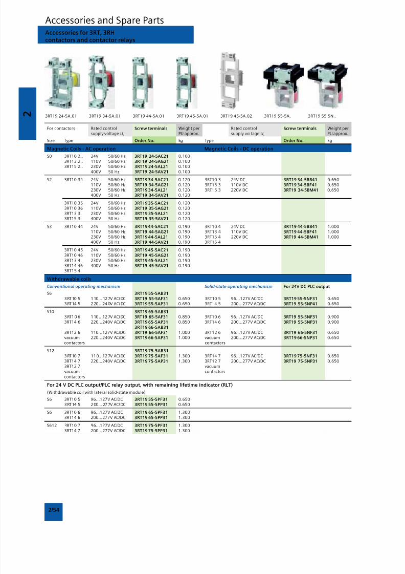
8/12/2019 SIRIUS Datasheet P-1
http://slidepdf.com/reader/full/sirius-datasheet-p-1 70/100
2
2/54
Accessories and Spare PartsAccessories for 3RT, 3RHcontactors and contactor relays
For contactors Rated control Screw terminals Weight per Rated control Screw terminals Weight persupply voltage Us PU approx. supply voltage Us PU approx.
Size Type Order No. kg Type Order No. kg
Magnetic Coils - AC operation Magnetic Coils - DC operation
S0 3RT10 2.. 24V 50/60 Hz 3RT19 24-5AC21 0.1003RT13 2.. 110V 50/60 Hz 3RT19 24-5AG21 0.1003RT15 2.. 230V 50/60 Hz 3RT19 24-5AL21 0.100
400V 50 Hz 3RT19 24-5AV21 0.100
S2 3RT10 34 24V 50/60 Hz 3RT19 34-5AC21 0.120 3RT10 3 24V DC 3RT19 34-5BB41 0.650110V 50/60 Hz 3RT19 34-5AG21 0.120 3RT13 3 110V DC 3RT19 34-5BF41 0.650230V 50/60 Hz 3RT19 34-5AL21 0.120 3RT15 3 220V DC 3RT19 34-5BM41 0.650400V 50 Hz 3RT19 34-5AV21 0.120
3RT10 35 24V 50/60 Hz 3RT19 35-5AC21 0.1203RT10 36 110V 50/60 Hz 3RT19 35-5AG21 0.1203RT13 3. 230V 50/60 Hz 3RT19 35-5AL21 0.1203RT15 3. 400V 50 Hz 3RT19 35-5AV21 0.120
S3 3RT10 44 24V 50/60 Hz 3RT19 44-5AC21 0.190 3RT10 4 24V DC 3RT19 44-5BB41 1.000110V 50/60 Hz 3RT19 44-5AG21 0.190 3RT13 4 110V DC 3RT19 44-5BF41 1.000230V 50/60 Hz 3RT19 44-5AL21 0.190 3RT15 4 220V DC 3RT19 44-5BM41 1.000400V 50 Hz 3RT19 44-5AV21 0.190 3RT15 4
3RT10 45 24V 50/60 Hz 3RT19 45-5AC21 0.1903RT10 46 110V 50/60 Hz 3RT19 45-5AG21 0.1903RT13 4. 230V 50/60 Hz 3RT19 45-5AL21 0.1903RT14 46 400V 50 Hz 3RT19 45-5AV21 0.1903RT15 4.
Withdrawable coils
Conventional operating mechanism Solid-state operating mechanism For 24V DC PLC output
S6 3RT19 55-5AB313 RT10 5 1 10. ..12 7V AC/ DC 3RT19 55-5AF31 0.650 3RT10 5 96...127V AC/DC 3RT19 55-5NF31 0.6503 RT14 5 2 20 .. .24 0V AC/ DC 3RT19 55-5AP31 0.650 3RT14 5 200...277V AC/DC 3RT19 55-5NP41 0.650
S10 3RT19 65-5AB313 RT1 0 6 1 10 .. .12 7V AC/ DC 3RT19 65-5AF31 0.850 3RT10 6 96...127V AC/DC 3RT19 55-5NF31 0.9003RT14 6 220...240V AC/DC 3RT19 65-5AP31 0.850 3RT14 6 200...277V AC/DC 3RT19 55-5NP31 0.900
3RT19 66-5AB313RT12 6 110...127V AC/DC 3RT19 66-5AF31 1.000 3RT12 6 96...127V AC/DC 3RT19 66-5NF31 0.650vacuum 220...240V AC/DC 3RT19 66-5AP31 1.000 vacuum 200...277V AC/DC 3RT19 66-5NP31 0.650contactors contactors
S12 3RT19 75-5AB313 RT10 7 11 0.. .12 7V AC/ DC 3RT19 75-5AF31 1.300 3RT14 7 96...127V AC/DC 3RT19 75-5NF31 0.6503RT14 7 220...240V AC/DC 3RT19 75-5AP31 1.300 3RT12 7 200...277V AC/DC 3RT19 75-5NP31 0.6503RT12 7 vacuumvacuum contactorscontactors
For 24 V DC PLC output/PLC relay output, with remaining lifetime indicator (RLT)
(Withdrawable coil with lateral solid-state module)
S6 3RT10 5 96...127V AC/DC 3RT19 55-5PF31 0.6503 RT14 5 2 00. ..27 7V AC/ DC 3RT19 55-5PP31 0.650
S6 3RT10 6 96...127V AC/DC 3RT19 65-5PF31 1.3003RT14 6 200...277V AC/DC 3RT19 65-5PP31 1.300
S612 3RT10 7 96...127V AC/DC 3RT19 75-5PF31 1.3003RT14 7 200...277V AC/DC 3RT19 75-5PP31 1.300
3RT19 24-5A.01 3RT19 34-5A.01 3RT19 44-5A.01 3RT19 45-5A.01 3RT19 45-5A.02 3RT19 55-5A. 3RT19 55.5N..
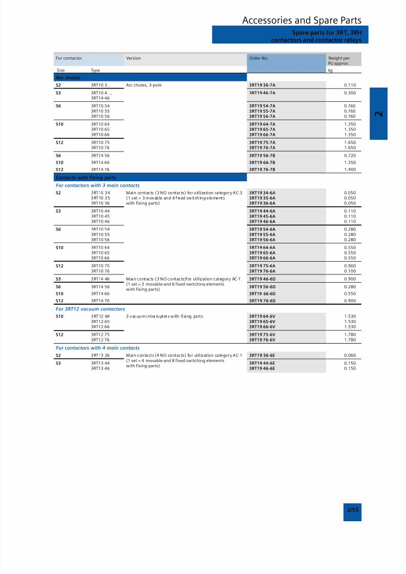
8/12/2019 SIRIUS Datasheet P-1
http://slidepdf.com/reader/full/sirius-datasheet-p-1 71/100
2
2/55
Accessories and Spare PartsSpare parts for 3RT, 3RH
contactors and contactor relays
For contactor Version Order No. Weight perPU approx.
Size Type kg
Arc chutes
S2 3RT10 3 . Arc chutes, 3-pole 3RT19 36-7A 0.110
S3 3RT10 4 . , 3RT19 46-7A 0.3003RT14 46
S6 3RT10 54 3RT19 54-7A 0.7603RT10 55 3RT19 55-7A 0.7603RT10 56 3RT19 56-7A 0.760
S10 3RT10 64 3RT19 64-7A 1.3503RT10 65 3RT19 65-7A 1.3503RT10 66 3RT19 66-7A 1.350
S12 3RT10 75 3RT19 75-7A 1.6503RT10 76 3RT19 76-7A 1.650
S6 3RT14 56 3RT19 56-7B 0.720
S10 3RT14 66 3RT19 66-7B 1.350
S12 3RT14 76 3RT19 76-7B 1.400
Contacts with fixing parts
For contactors with 3 main contacts
S2 3RT10 34 Main contacts (3 NO contacts) for utilization category AC-3 3RT19 34-6A 0.0503RT10 35 (1 set = 3 movable and 6 f ixed switching e lements 3RT19 35-6A 0.0503RT10 36 with fixing parts) 3RT19 36-6A 0.050
S3 3RT10 44 3RT19 44-6A 0.1103RT10 45 3RT19 45-6A 0.1103RT10 46 3RT19 46-6A 0.110
S6 3RT10 54 3RT19 54-6A 0.2803RT10 55 3RT19 55-6A 0.2803RT10 56 3RT19 56-6A 0.280
S10 3RT10 64 3RT19 64-6A 0.5503RT10 65 3RT19 65-6A 0.5503RT10 66 3RT19 66-6A 0.550
S12 3RT10 75 3RT19 75-6A 0.9003RT10 76 3RT19 76-6A 0.100
S3 3RT14 46 Main contacts (3 NO contacts)for util ization category AC-1 3RT19 46-6D 0.900
S6 3RT14 56(1 set = 3 movable and 6 fixed switching elements
3RT19 56-6D 0.280
S10 3RT14 66with fixing parts)
3RT19 66-6D 0.550
S12 3RT14 76 3RT19 76-6D 0.900
For 3RT12 vacuum contactors
S10 3RT12 64 3 vacuum interrupters with fixing parts 3RT19 64-6V 1.5303RT12 65 3RT19 65-6V 1.5303RT12 66 3RT19 66-6V 1.530
S12 3RT12 75 3RT19 75-6V 1.7803RT12 76 3RT19 76-6V 1.780
For contactors with 4 main contacts
S2 3RT13 26 Main contacts (4 NO contacts) for util ization category AC-1 3RT19 36-6E 0.060
S3 3RT13 44(1 set = 4 movable and 8 fixed switching elements
3RT19 44-6E 0.1503RT13 46
with fixing parts)3RT19 46-6E 0.150
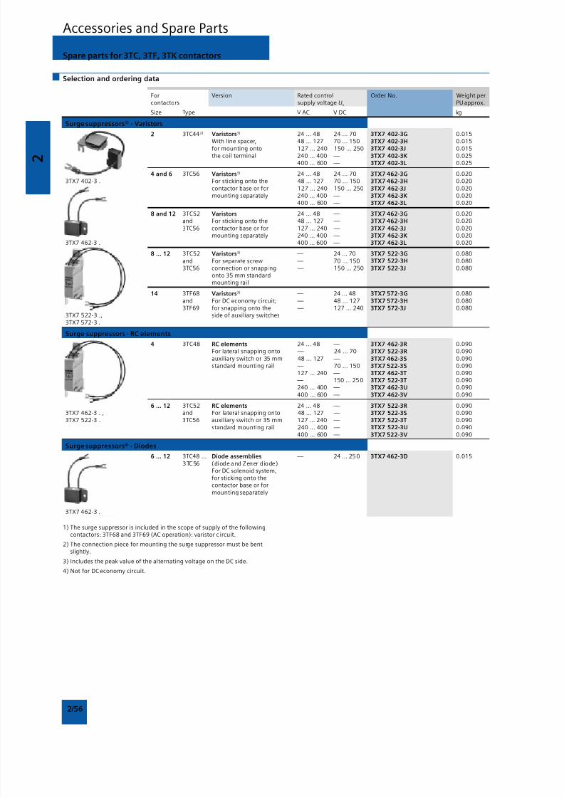
8/12/2019 SIRIUS Datasheet P-1
http://slidepdf.com/reader/full/sirius-datasheet-p-1 72/100
2
2/56
Accessories and Spare Parts
Spare parts for 3TC, 3TF, 3TK contactors
Selection and ordering data
For Version Rated control Order No. Weight percontactors supply voltage Us PU approx.
Size Type V AC V DC kg
Surge suppressors1) · Varistors
2 3TC442) Varistors3) 24 ... 48 24 ... 70 3TX7 402-3G 0.015
With line spacer, 48 ... 127 70 ... 150 3TX7 402-3H 0.015for mounting onto 127 ... 240 150 ... 250 3TX7 402-3J 0.015the coil terminal 240 ... 400 — 3TX7 402-3K 0.025
400 ... 600 — 3TX7 402-3L 0.025
4 and 6 3TC56 Varistors3) 24 ... 48 24 ... 70 3TX7 462-3G 0.0203TX7 402-3 . For sticking onto the 48 ... 127 70 ... 150 3TX7 462-3H 0.020
contactor base or for 127 ... 240 150 ... 250 3TX7 462-3J 0.020mounting separately 240 ... 400 — 3TX7 462-3K 0.020
400 ... 600 — 3TX7 462-3L 0.020
8 and 12 3TC52 Varistors 24 ... 48 — 3TX7 462-3G 0.020and For sticking onto the 48 ... 127 — 3TX7 462-3H 0.0203TC56 contactor base or for 127 ... 240 — 3TX7 462-3J 0.020
mounting separately 240 ... 400 — 3TX7 462-3K 0.0203TX7 462-3 . 400 ... 600 — 3TX7 462-3L 0.020
8 ... 12 3TC52 Varistors3) — 24 ... 70 3TX7 522-3G 0.080and For separate screw — 70 ... 150 3TX7 522-3H 0.0803TC56 connection or snapping — 150 ... 250 3TX7 522-3J 0.080
onto 35 mm standardmounting rail
14 3TF68 Varistors3) — 24 ... 48 3TX7 572-3G 0.080and For DC economy circuit; — 48 ... 127 3TX7 572-3H 0.0803TF69 for snapping onto the — 127 ... 240 3TX7 572-3J 0.080
3TX7 522-3 ., side of auxiliary switches3TX7 572-3 .
Surge suppressors · RC elements
4 3TC48 RC elements 24 ... 48 — 3TX7 462-3R 0.090For lateral snapping onto — 24 ... 70 3TX7 522-3R 0.090auxiliary switch or 35 mm 48 ... 127 — 3TX7 462-3S 0.090standard mounting rail — 70 ... 150 3TX7 522-3S 0.090
127 ... 240 — 3TX7 462-3T 0.090 — 150 ... 25 0 3TX7 522-3T 0.090240 ... 400 — 3TX7 462-3U 0.090400 ... 600 — 3TX7 462-3V 0.090
6 ... 12 3TC52 RC elements 24 ... 48 — 3TX7 522-3R 0.0903TX7 462-3 . , and For lateral snapping onto 48 ... 127 — 3TX7 522-3S 0.090
3TX7 522-3 . 3TC56 auxiliary switch or 35 mm 127 ... 240 — 3TX7 522-3T 0.090standard mounting rail 240 ... 400 — 3TX7 522-3U 0.090
400 ... 600 — 3TX7 522-3V 0.090
Surge suppressors4) · Diodes
6 ... 12 3TC48 ... Diode assemblies — 24 ... 25 0 3TX7 462-3D 0.0153TC56 (diode and Zener diode)
For DC solenoid system,for sticking onto thecontactor base or formounting separately
3TX7 462-3 .
1) The surge suppressor is included in the scope of supply of the followingcontactors: 3TF68 and 3TF69 (AC operation): varistor c ircuit.
2) The connection piece for mounting the surge suppressor must be bentslightly.
3) Includes the peak value of the alternating voltage on the DC side.
4) Not for DC economy circuit.
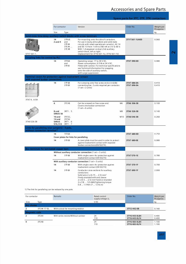
8/12/2019 SIRIUS Datasheet P-1
http://slidepdf.com/reader/full/sirius-datasheet-p-1 73/100
2
2/57
Accessories and Spare Parts
Spare parts for 3TC, 3TF, 3TK contactors
For contactor Version Order No. Weight perPU approx.
Size Type kg
Solid-state time-delay auxiliary switch blocks with screw terminals
14 3 TF6 8 For mounting onto the s ide of conta ctors . 3TY7 561-1UA00 0.0602 and 4 and Fo r use in dusty atmos phere and solid-state
3 TF 69 c ircui ts with ra ted operat ional currents Ie AC-14
3TC44 ... and DC-13 from 1 mA to 300 mA at 3 V to 60 V.3 TC 48 W ith 1 changeover cont act.2 nd au xi li ary
switch block, left or right5TY7 561-1 . (replacement for 3TY6 561-1U, 3TY6 561-1V)
Coupling links for control by PLC
14 3TF68 Operating range: 17 to 30 V DC. 3TX7 090-0D 0.080and Power consumption: 0.5 W at 24 V DC.3TF69 Fit ted with var istor. For technical specif icat ions
see Technical Information For snappingonto the side of auxiliary switch,with surge suppression
Terminal covers for protection against inadvertent contactwith exposed busbar connections
14 3 TF 68 For screwing onto free screw end on middle 3TX7 686-0A 0.4103TF69 connect ing bar. 2 units required per contactor. 3TX7 696-0A 0.410
(1 set = 2 units)
3TX7 6 . 6-0A
6 3TC48 Can be screwed on free screw end. M6 3TX6 506-3B 0.100Covers one busbar connection(1 set = 6 units).
8 and 3RT1 . 5 M8 3TX6 526-3B 0.140SIRIUS S6
10 and 3TC52, M10 3TX6 546-3B 0.26014 and 3TC56
3TX6 526-3B SIRIUS 3RT1 . 6S10, S12 3RT1 . 7
Links for paralleling (star jumpers) · 3-pole,without connection terminal1)
14 3TF68 3TX7 680-0D 0.250
Cover plates for links for paralleling
14 3TF68 A cover plate must be used in order to protect 3TX7 680-0E 0.080against inadvertent contact with exposedbusbar connections(EN 50274).
Box terminals for laminated copper bars
Without auxiliary conductor connection (1 set = 3 units)
14 3 TF 68 With s ingle covers for protection against 3TX7 570-1E 0.780inadvertent contact (EN 50274)
With auxiliary conductor connection (1 set = 3 units)
14 3 TF 68 With s ingle covers for protection against 3TX7 570-1F 0.700inadvertent contact (EN 50274)
14 3 TF 69 Conductor c ross -sections for a ux il ia ry 3TX7 690-1F 2.000conductors:Solid wire 2 x (0.75 ... 2.5) mm2
Finely stranded with end sleeve2 x (0.5 ... 2.5) mm2 Solid or stranded2 x (18 ... 12) AWGTightening torque
0.8 ... 1.4 Nm (7 ... 12 lb.in)
1) The link for paralleling can be reduced by one pole.
For contactor Remarks Rated control Order No. Weight persupply voltage Us PU approx.
Size Type V DC kg
Arc chutes
2 3TC44 17-0L . . With cutout for mounting resistor 3TY2 442-0B 0.160
Magnetic coils
2 3TC44 With series resistorWithout varistor 24 3TY6 443-0LB4 0.400110 3TY6 443-0LF4 0.400
4 3TC48 24 3TY6 483-0LB4 1.100110 3TY6 483-0LF4 1.100
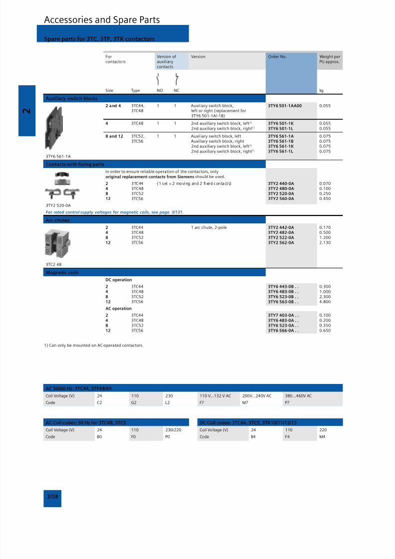
8/12/2019 SIRIUS Datasheet P-1
http://slidepdf.com/reader/full/sirius-datasheet-p-1 74/100
2
2/58
Accessories and Spare Parts
Spare parts for 3TC, 3TF, 3TK contactors
For Version of Version Order No. Weight percontactors auxiliary PU approx.
contacts
Size Type NO NC kg
Auxiliary switch blocks2 and 4 3TC44, 1 1 Auxiliary switch block, 3TY6 501-1AA00 0.055
3TC48 left or right (replacement for3TY6 501-1A/-1B)
4 3TC48 1 1 2nd auxiliary switch block, left1) 3TY6 501-1K 0.0552nd auxiliary switch block, right1) 3TY6 501-1L 0.055
8 and 12 3TC52, 1 1 Auxiliary switch block, left 3TY6 561-1A 0.0753TC56 Auxiliary switch block, right 3TY6 561-1B 0.075
2nd auxiliary switch block, left1) 3TY6 561-1K 0.0752nd auxiliary switch block, right1) 3TY6 561-1L 0.075
3TY6 561-1A
Contacts with fixing parts
In order to ensure reliable operation of the contactors, only
original replacement contacts from Siemens should be used.
2 3TC44 (1 set = 2 moving and 2 fixed contacts) 3TY2 440-0A 0.0704 3TC48 3TY2 480-0A 0.100
8 3TC52 3TY2 520-0A 0.25012 3TC56 3TY2 560-0A 0.450
3TY2 520-0A
For rated control supply voltages for magnetic coils, see page 3/131.
Arc chutes
2 3TC44 1 arc chute, 2-pole 3TY2 442-0A 0.1704 3TC48 3TY2 482-0A 0.5008 3TC52 3TY2 522-0A 1.20012 3TC56 3TY2 562-0A 2.130
3TC2 48
Magnetic coils
DC operation
2 3TC44 3TY6 443-0B . . 0.300
4 3TC48 3TY6 483-0B . . 1.0008 3TC52 3TY6 523-0B . . 2.30012 3TC56 3TY6 563-0B . . 4.800
AC operation
2 3TC44 3TY7 403-0A . . 0.100
4 3TC48 3TY6 483-0A . . 0.2008 3TC52 3TY6 523-0A . . 0.35012 3TC56 3TY6 566-0A . . 0.650
1) Can only be mounted on AC-operated contactors.
AC 50/60 Hz: 3TC44, 3TF68/69
Coil Voltage (V) 24 110 230 110 V...132 V AC 200V...240V AC 380...460V AC
Code C2 G2 L2 F7 M7 P7
AC Coil codes: 50 Hz for 3TC48, 3TC5
Coil Voltage (V) 24 110 230/220
Code B0 F0 P0
DC Coil codes: 3TC44, 3TC5, 3TK10/11/12/13
Coil Voltage (V) 24 110 220
Code B4 F4 M4
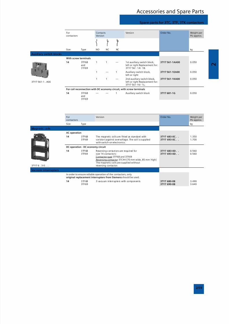
8/12/2019 SIRIUS Datasheet P-1
http://slidepdf.com/reader/full/sirius-datasheet-p-1 75/100
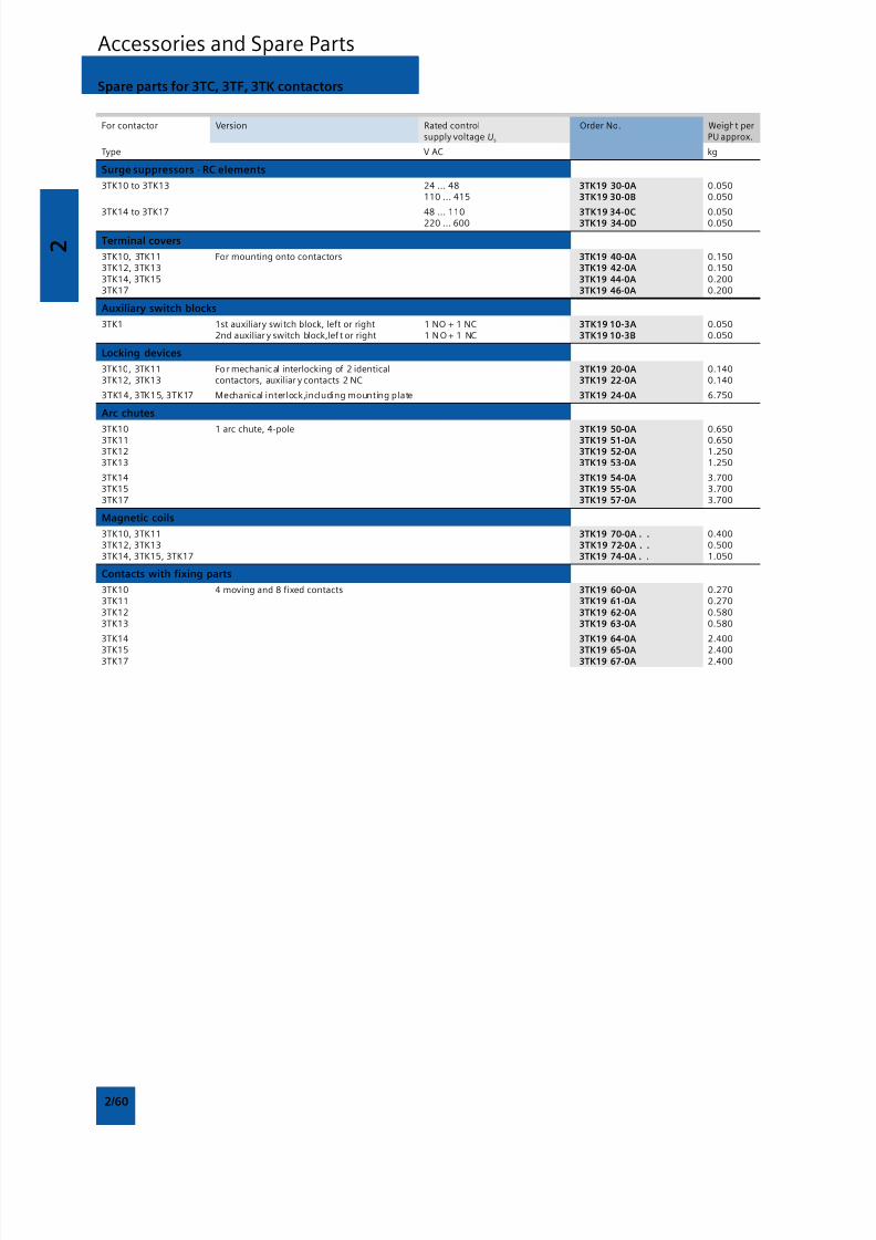
8/12/2019 SIRIUS Datasheet P-1
http://slidepdf.com/reader/full/sirius-datasheet-p-1 76/100
2
2/60
Accessories and Spare Parts
Spare parts for 3TC, 3TF, 3TK contactors
For contactor Version Rated control Order No. Weight persupply voltage Us PU approx.
Type V AC kg
Surge suppressors · RC elements
3TK10 to 3TK13 24 ... 48 3TK19 30-0A 0.050110 ... 415 3TK19 30-0B 0.050
3TK14 to 3TK17 48 ... 1103TK19 34-0C
0.050220 ... 600 3TK19 34-0D 0.050
Terminal covers
3TK10, 3TK11 For mounting onto contactors 3TK19 40-0A 0.1503TK12, 3TK13 3TK19 42-0A 0.1503TK14, 3TK15 3TK19 44-0A 0.2003TK17 3TK19 46-0A 0.200
Auxiliary switch blocks
3TK1 1st auxiliary switch block, left or right 1 NO + 1 NC 3TK19 10-3A 0.0502nd auxiliar y switch block,lef t or right 1 N O + 1 NC 3TK19 10-3B 0.050
Locking devices
3TK10, 3TK11 Fo r mechanic al interlocking of 2 identical 3TK19 20-0A 0.1403TK12, 3TK13 contactors, auxiliar y contacts 2 NC 3TK19 22-0A 0.140
3TK14, 3TK15, 3TK17 Mechanical interlock,including mounting plate 3TK19 24-0A 6.750
Arc chutes
3TK10 1 arc chute, 4-pole 3TK19 50-0A 0.6503TK11 3TK19 51-0A 0.6503TK12 3TK19 52-0A 1.2503TK13 3TK19 53-0A 1.250
3TK14 3TK19 54-0A 3.7003TK15 3TK19 55-0A 3.7003TK17 3TK19 57-0A 3.700
Magnetic coils
3TK10, 3TK11 3TK19 70-0A . . 0.4003TK12, 3TK13 3TK19 72-0A . . 0.5003TK14, 3TK15, 3TK17 3TK19 74-0A . . 1.050
Contacts with fixing parts
3TK10 4 moving and 8 fixed contacts 3TK19 60-0A 0.2703TK11 3TK19 61-0A 0.2703TK12 3TK19 62-0A 0.5803TK13 3TK19 63-0A 0.580
3TK14 3TK19 64-0A 2.400
3TK15 3TK19 65-0A 2.4003TK17 3TK19 67-0A 2.400
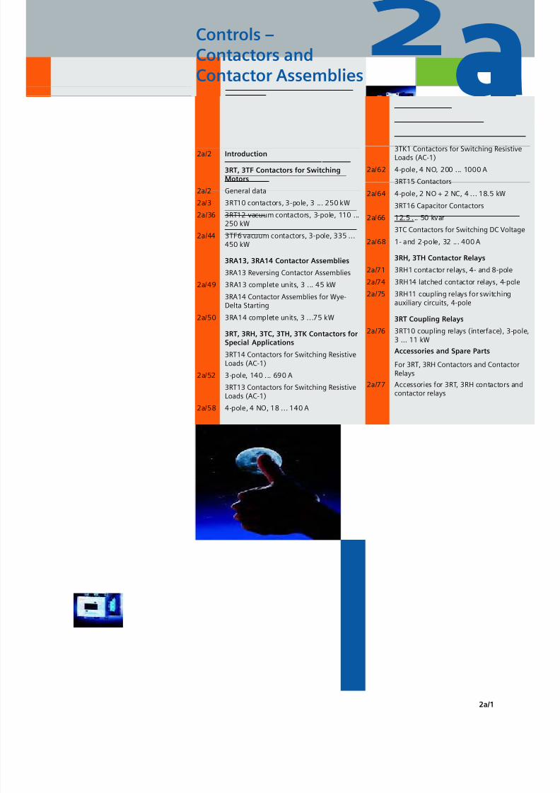
8/12/2019 SIRIUS Datasheet P-1
http://slidepdf.com/reader/full/sirius-datasheet-p-1 77/100
2 a
2a/1
aControls –Contactors andContactor Assemblies
2a/2 Introduction
3RT, 3TF Contactors for SwitchingMotors
2a/2 General data
2a/3 3RT10 contactors, 3-pole, 3 ... 250 kW
2a/36 3RT12 vacuum contactors, 3-pole, 110 ...250 kW
2a/44 3TF6 vacuum contactors, 3-pole, 335 ...450 kW
3RA13, 3RA14 Contactor Assemblies
3RA13 Reversing Contactor Assemblies
2a/49 3RA13 complete units, 3 ... 45 kW
3RA14 Contactor Assemblies for Wye-Delta Starting
2a/50 3RA14 complete units, 3 ...75 kW
3RT, 3RH, 3TC, 3TH, 3TK Contactors forSpecial Applications
3RT14 Contactors for Switching ResistiveLoads (AC-1)
2a/52 3-pole, 140 ... 690 A
3RT13 Contactors for Switching ResistiveLoads (AC-1)
2a/58 4-pole, 4 NO, 18 ... 140 A
3TK1 Contactors for Switching ResistiveLoads (AC-1)
2a/62 4-pole, 4 NO, 200 ... 1000 A
3RT15 Contactors
2a/64 4-pole, 2 NO + 2 NC, 4 ... 18.5 kW
3RT16 Capacitor Contactors
2a/66 12.5 ... 50 kvar
3TC Contactors for Switching DC Voltage
2a/68 1- and 2-pole, 32 ... 400 A
3RH, 3TH Contactor Relays
2a/71 3RH1 contactor relays, 4- and 8-pole
2a/74 3RH14 latched contactor relays, 4-pole
2a/75 3RH11 coupling relays for switchingauxiliary circuits, 4-pole
3RT Coupling Relays
2a/76 3RT10 coupling relays (interface), 3-pol3 ... 11 kW
Accessories and Spare Parts
For 3RT, 3RH Contactors and ContactorRelays
2a/77 Accessories for 3RT, 3RH contactors andcontactor relays
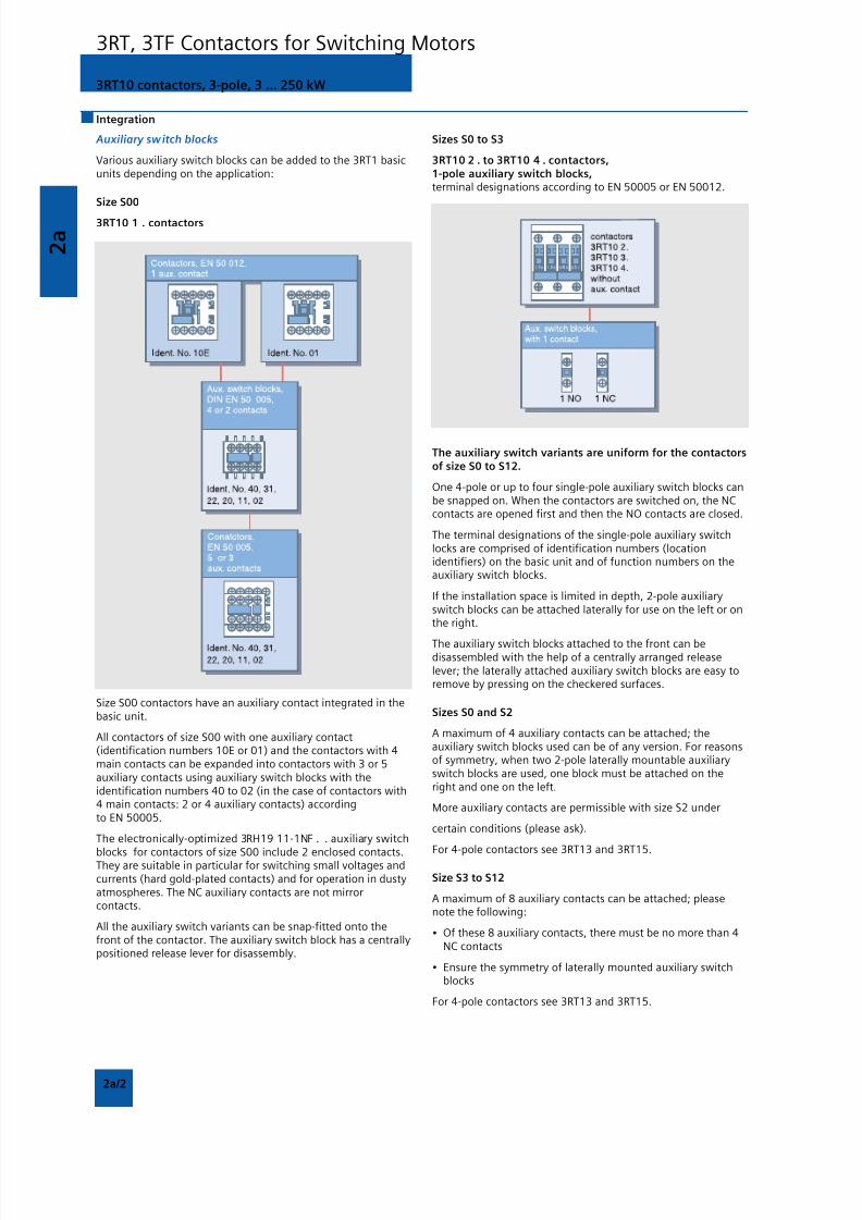
8/12/2019 SIRIUS Datasheet P-1
http://slidepdf.com/reader/full/sirius-datasheet-p-1 78/100
2 a
2a/2
3RT10 contactors, 3-pole, 3 ... 250 kW
3RT, 3TF Contactors for Switching Motors
Integration
Auxiliary switch blocks
Various auxiliary switch blocks can be added to the 3RT1 basicunits depending on the application:
Size S00
3RT10 1 . contactors
Size S00 contactors have an auxiliary contact integrated in thebasic unit.
All contactors of size S00 with one auxiliary contact(identification numbers 10E or 01) and the contactors with 4main contacts can be expanded into contactors with 3 or 5auxiliary contacts using auxiliary switch blocks with theidentification numbers 40 to 02 (in the case of contactors with4 main contacts: 2 or 4 auxiliary contacts) accordingto EN 50005.
The electronically-optimized 3RH19 11-1NF . . auxiliary switch
blocks for contactors of size S00 include 2 enclosed contacts.They are suitable in particular for switching small voltages andcurrents (hard gold-plated contacts) and for operation in dustyatmospheres. The NC auxiliary contacts are not mirrorcontacts.
All the auxiliary switch variants can be snap-fitted onto thefront of the contactor. The auxiliary switch block has a centrallypositioned release lever for disassembly.
Sizes S0 to S3
3RT10 2 . to 3RT10 4 . contactors,1-pole auxiliary switch blocks,terminal designations according to EN 50005 or EN 50012.
The auxiliary switch variants are uniform for the contactorsof size S0 to S12.
One 4-pole or up to four single-pole auxiliary switch blocks canbe snapped on. When the contactors are switched on, the NCcontacts are opened first and then the NO contacts are closed.
The terminal designations of the single-pole auxiliary switchlocks are comprised of identification numbers (locationidentifiers) on the basic unit and of function numbers on theauxiliary switch blocks.
If the installation space is limited in depth, 2-pole auxiliaryswitch blocks can be attached laterally for use on the left or onthe right.
The auxiliary switch blocks attached to the front can bedisassembled with the help of a centrally arranged releaselever; the laterally attached auxiliary switch blocks are easy toremove by pressing on the checkered surfaces.
Sizes S0 and S2
A maximum of 4 auxiliary contacts can be attached; theauxiliary switch blocks used can be of any version. For reasonsof symmetry, when two 2-pole laterally mountable auxiliaryswitch blocks are used, one block must be attached on theright and one on the left.
More auxiliary contacts are permissible with size S2 under
certain conditions (please ask).
For 4-pole contactors see 3RT13 and 3RT15.
Size S3 to S12
A maximum of 8 auxiliary contacts can be attached; pleasenote the following:
• Of these 8 auxiliary contacts, there must be no more than 4NC contacts
• Ensure the symmetry of laterally mounted auxiliary switchblocks
For 4-pole contactors see 3RT13 and 3RT15.
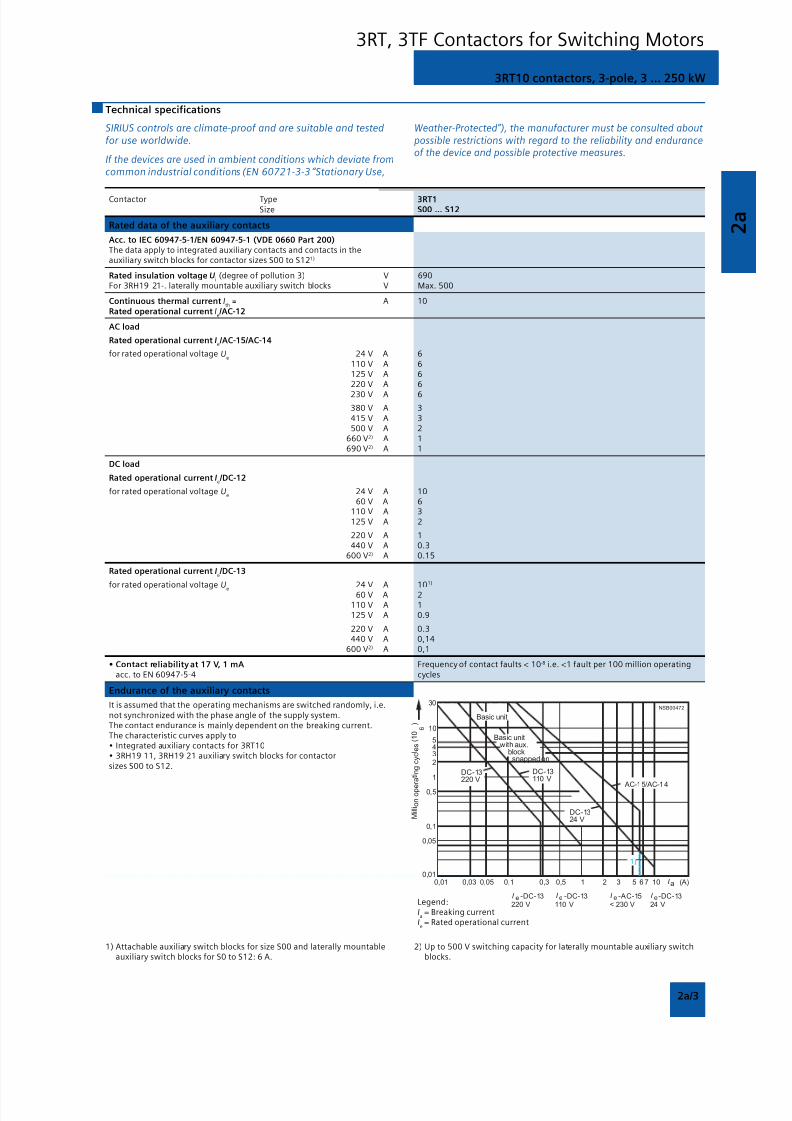
8/12/2019 SIRIUS Datasheet P-1
http://slidepdf.com/reader/full/sirius-datasheet-p-1 79/100
2 a
2a/3
3RT10 contactors, 3-pole, 3 ... 250 kW
3RT, 3TF Contactors for Switching Motors
Technical specifications
SIRIUS controls are climate-proof and are suitable and testedfor use worldwide.
If the devices are used in ambient conditions which deviate fromcommon industrial conditions (EN 60721-3-3 “Stationary Use,
Weather-Protected”), the manufacturer must be consulted aboutpossible restrictions with regard to the reliability and enduranceof the device and possible protective measures.
Contactor Type 3RT1 Size S00 ... S12
Rated data of the auxiliary contacts
Acc. to IEC 60947-5-1/EN 60947-5-1 (VDE 0660 Part 200)The data apply to integrated auxiliary contacts and contacts in theauxiliary switch blocks for contactor sizes S00 to S121)
Rated insulation voltage Ui (degree of pollution 3) V 690
For 3RH19 21-. laterally mountable auxiliary switch blocks V Max. 500
Continuous thermal current Ith
= A 10
Rated operational current Ie /AC-12
AC load
Rated operational current Ie /AC-15/AC-14
for rated operational voltage Ue
24 V A 6110 V A 6125 V A 6220 V A 6
230 V A 6
380 V A 3415 V A 3500 V A 2
660 V2) A 1690 V2) A 1
DC load
Rated operational current Ie /DC-12
for rated operational voltage Ue
24 V A 1060 V A 6
110 V A 3125 V A 2
220 V A 1440 V A 0.3
600 V2) A 0.15
Rated operational current Ie /DC-13
for rated operational voltage Ue 24 V A 10
1)
60 V A 2110 V A 1125 V A 0.9
220 V A 0.3440 V A 0,14
600 V2) A 0,1
• Contact reliability at 17 V, 1 mA Frequency of contact faults < 10-8 i.e. <1 fault per 100 million operatingacc. to EN 60947-5-4 cycles
Endurance of the auxiliary contacts
It is assumed that the operating mechanisms are switched randomly, i.e.not synchronized with the phase angle of the supply system.The contact endurance is mainly dependent on the breaking current.The characteristic curves apply to• Integrated auxiliary contacts for 3RT10• 3RH19 11, 3RH19 21 auxiliary switch blocks for contactorsizes S00 to S12.
Legend:Ia = Breaking current
Ie = Rated operational current
1) Attachable auxiliary switch blocks for size S00 and laterally mountableauxiliary switch blocks for S0 to S12: 6 A.
2) Up to 500 V switching capacity for laterally mountable auxiliary switchblocks.
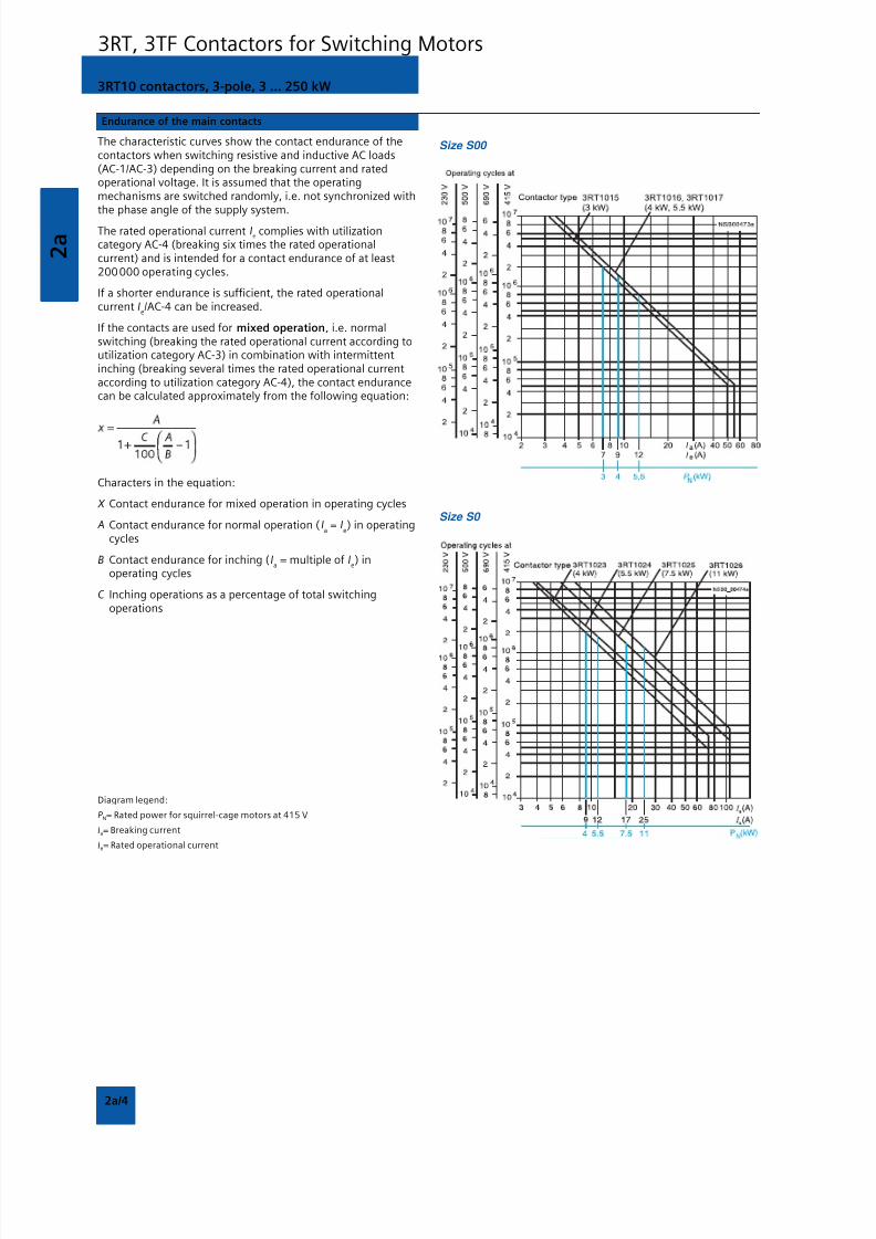
8/12/2019 SIRIUS Datasheet P-1
http://slidepdf.com/reader/full/sirius-datasheet-p-1 80/100
2 a
2a/4
3RT10 contactors, 3-pole, 3 ... 250 kW
3RT, 3TF Contactors for Switching Motors
Endurance of the main contacts
The characteristic curves show the contact endurance of thecontactors when switching resistive and inductive AC loads(AC-1/AC-3) depending on the breaking current and ratedoperational voltage. It is assumed that the operatingmechanisms are switched randomly, i.e. not synchronized withthe phase angle of the supply system.
The rated operational current Ie complies with utilization
category AC-4 (breaking six times the rated operationalcurrent) and is intended for a contact endurance of at least200000 operating cycles.
If a shorter endurance is sufficient, the rated operationalcurrent I
e/AC-4 can be increased.
If the contacts are used for mixed operation, i.e. normalswitching (breaking the rated operational current according toutilization category AC-3) in combination with intermittentinching (breaking several times the rated operational currentaccording to utilization category AC-4), the contact endurancecan be calculated approximately from the following equation:
Characters in the equation:
X Contact endurance for mixed operation in operating cycles
A Contact endurance for normal operation (Ia = I
e) in operating
cycles
B Contact endurance for inching (Ia = multiple of I
e) in
operating cycles
C Inching operations as a percentage of total switchingoperations
Diagram legend:
P N= Rated power for squirrel-cage motors at 415 V
Ia= Breaking current
Ie= Rated operational current
Size S00
Size S0
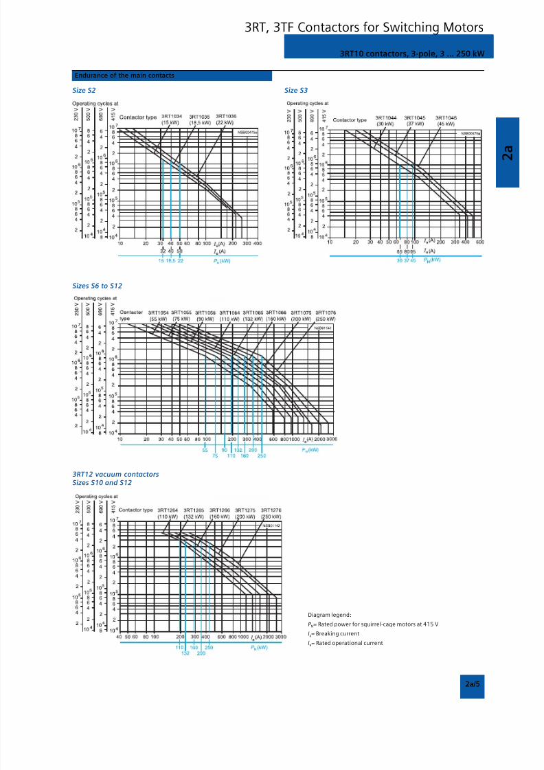
8/12/2019 SIRIUS Datasheet P-1
http://slidepdf.com/reader/full/sirius-datasheet-p-1 81/100
2 a
2a/5
3RT10 contactors, 3-pole, 3 ... 250 kW
3RT, 3TF Contactors for Switching Motors
Endurance of the main contacts
Size S2
Sizes S6 to S12
3RT12 vacuum contactorsSizes S10 and S12
Size S3
Diagram legend:
P N= Rated power for squirrel-cage motors at 415 V
Ia= Breaking current
Ie= Rated operational current
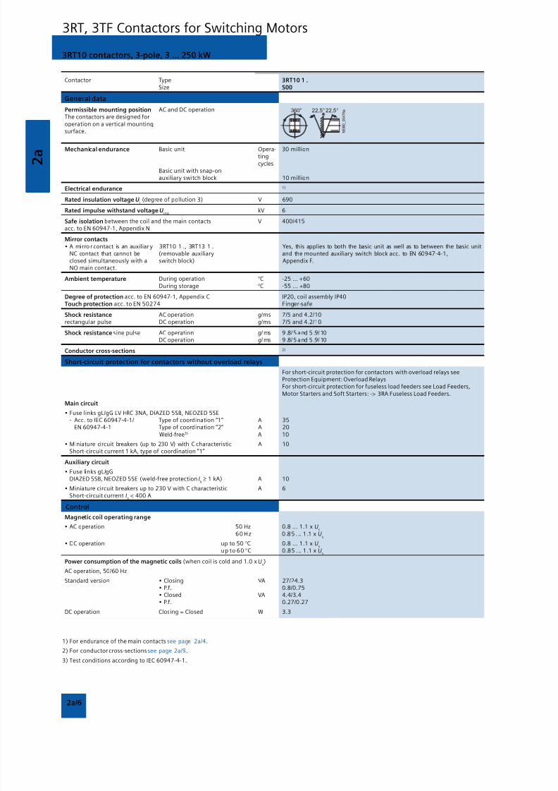
8/12/2019 SIRIUS Datasheet P-1
http://slidepdf.com/reader/full/sirius-datasheet-p-1 82/100
2 a
2a/6
3RT10 contactors, 3-pole, 3 ... 250 kW
3RT, 3TF Contactors for Switching Motors
Contactor Type 3RT10 1 . Size S00
General data
Permissible mounting position AC and DC operationThe contactors are designed foroperation on a vertical mountingsurface.
Mechanical endurance Basic unit Opera- 30 milliontingcycles
Basic unit with snap-onauxiliary switch block 10 million
Electrical endurance 1)
Rated insulation voltage Ui (degree of pollution 3) V 690
Rated impulse withstand voltage Uimp
kV 6
Safe isolation between the coil and the main contacts V 400/415acc. to EN 60947-1, Appendix N
Mirror contacts• A mirro r contact is an auxiliar y 3RT10 1 ., 3RT13 1 . Yes, this applies to both the basic unit as well as to between the basic unit
NC contact that cannot be (removable auxiliary and the mounted auxiliary switch block acc. to EN 60947-4-1,closed simultaneously with a switch block) Appendix F.NO main contact.
Ambient temperature During operation °C -25 ... +60During storage °C -55 ... +80
Degree of protection acc. to EN 60947-1, Appendix C IP20, coil assembly IP40Touch protection acc. to EN 50274 Finger-safe
Shock resistance AC operation g/ms 7/5 and 4.2/10rectangular pulse DC operation g/ms 7/5 and 4.2/10
Shock resistance sine pulse AC operation g/ ms 9 .8/ 5 a nd 5 .9/ 10DC operation g/ ms 9 .8/ 5 a nd 5 .9/ 10
Conductor cross-sections 2)
Short-circuit protection for contactors without overload relays
For short-circuit protection for contactors with overload relays seeProtection Equipment: Overload RelaysFor short-circuit protection for fuseless load feeders see Load Feeders,Motor Starters and Soft Starters: -> 3RA Fuseless Load Feeders.
Main circuit
• Fuse links gL/gG LV HRC 3NA, DIAZED 5SB, NEOZED 5SE- Acc. to IEC 60947-4-1/ Type of coordination “1” A 35EN 60947-4-1 Type of coordination “2” A 20 Weld-free3) A 10
• Miniature circuit breakers (up to 230 V) with C characteristic A 10Short-circuit current 1 kA, type of coordination “1”
Auxiliary circuit
• Fuse links gL/gGDIAZED 5SB, NEOZED 5SE (weld-free protection I
k ≥ 1 kA) A 10
• Miniature circuit breakers up to 230 V with C characteristic A 6Short-circuit current I
k < 400 A
Control
Magnetic coil operating range
• AC operation 50 Hz 0.8 ... 1.1 x Us
60 Hz 0.85 . .. 1.1 x Us
• DC operation up to 50 °C 0.8 ... 1.1 x Us
up to 60 °C 0.85 ... 1.1 x Us
Power consumption of the magnetic coils (when coil is cold and 1.0 x Us)
AC operation, 50/60 Hz
Standard version • Closing VA 27/24.3• P.f. 0.8/0.75• Closed VA 4.4/3.4• P.f. 0.27/0.27
DC operation Closing = Closed W 3.3
1) For endurance of the main contacts see page 2a/4.
2) For conductor cross-sections see page 2a/9.
3) Test conditions according to IEC 60947-4-1.
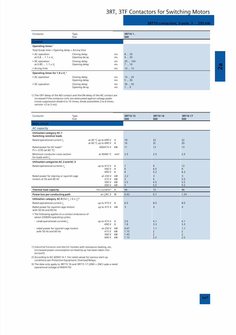
8/12/2019 SIRIUS Datasheet P-1
http://slidepdf.com/reader/full/sirius-datasheet-p-1 83/100
2 a
2a/7
3RT10 contactors, 3-pole, 3 ... 250 kW
3RT, 3TF Contactors for Switching Motors
1) The OFF-delay of the NO contact and the ON-delay of the NC contact areincreased if the contactor coils are attenuated against voltage peaks(noise suppression diode 6 to 10 times; diode assemblies 2 to 6 times,varistor +2 to 5 ms).
1) Industrial furnaces and electric heaters with resistance heating, etc.(increased power consumption on heating up has been taken intoaccount).
2) According to IEC 60947-4-1. For rated values for various start-upconditions see Protection Equipment: Overload Relays.
3) The data only apply to 3RT15 16 and 3RT15 17 (2NO + 2NC) upto a ratedoperational voltage of 400/415V
Contactor Type 3RT10 1 . Size S00
Control
Operating times1)
Total break time = Opening delay + Arcing time
• AC operation Closing delay ms 8 ... 35at 0.8 ... 1.1 x
UsOpening delay ms 4 ... 30
• DC operation Closing delay ms 25 ... 100at 0.85 ... 1.1 x U
sOpening delay ms 7 ... 10
• Arcing time ms 10 ... 15
Operating times for 1.0 x Us1)
• AC operation Closing delay ms 10 ... 25Opening delay ms 5 ... 30
• DC operation Closing delay ms 30 ... 50Opening delay ms 7 ... 9
Contactor Type 3RT10 15 3RT10 16 3RT10 17 Size S00 S00 S00
Main circuit
AC capacity
Utilization category AC-1Switching resistive loads
Rated operational current Ie
at 40 °C up to 690 V A 18 22 22at 60 °C up to 690 V A 16 20 20
Rated power for AC loads1) 400/415 V kW 11 13 13P.f.= 0.95 (at 60 °C)
Minimum conductor cross-section at 40/60 °C mm2 2.5 2.5 2.5for loads with I
e
Utilization categories AC-2 and AC-3
Rated operational currents Ie
up to 415 V A 7 9 12 500 V A 5 6.5 9 690 V A 4 5.2 6.3
Rated power for slipring or squirrel-cage at 230 V kW 2.2 3 3motors at 50 and 60 Hz 415 V kW 3 4 5.5
500 V kW 3.5 4.5 5.5690 V kW 4 5.5 5.5
Thermal load capacity 10 s current2) A 56 72 96
Power loss per conducting path at Ie/AC-3 W 0.42 0.7 1.24
Utilization category AC-4 (for Ia = 6 x I
e)3)
Rated operational current Ie
up to 415 V A 6.5 8.5 8.5
Rated power for squirrel-cage motors up to 415 V kW 3 4 4with 50 Hz and 60 Hz
• The following applies to a contact endurance ofabout 200000 operating cycles:
- rated operational currents Ie
up to 415 V A 2.6 4.1 4.1690 V A 1.8 3.3 3.3
- rated power for squirrel-cage motors at 230 V kW 0.67 1.1 1.1with 50 Hz and 60 Hz 415 V kW 1.15 2 2
500 V kW 1.45 2 2690 V kW 1.15 2.5 2.5
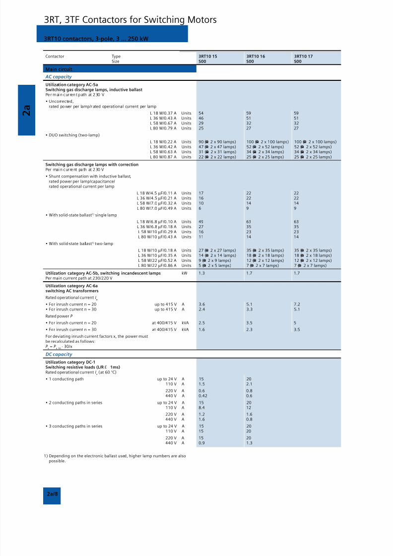
8/12/2019 SIRIUS Datasheet P-1
http://slidepdf.com/reader/full/sirius-datasheet-p-1 84/100
2 a
2a/8
3RT10 contactors, 3-pole, 3 ... 250 kW
3RT, 3TF Contactors for Switching Motors
1) Depending on the electronic ballast used, higher lamp numbers are alsopossible.
Contactor Type 3RT10 15 3RT10 16 3RT10 17 Size S00 S00 S00
Main circuit
AC capacity
Utilization category AC-5aSwitching gas discharge lamps, inductive ballastPe r main cur rent path at 2 30 V
• Uncorrected,rated po wer per lamp/r ated operational current per lamp
L 18 W/0.37 A Units 54 59 59L 36 W/0.43 A Units 46 51 51L 58 W/0.67 A Units 29 32 32L 80 W/0.79 A Units 25 27 27
• DUO switching (two-lamp)
L 18 W/0.22 A Units 90 ( 2 x 90 lamps) 100 ( 2 x 100 lamps) 100 ( 2 x 100 lamps) L 36 W/0.42 A Units 47 ( 2 x 47 lamps) 52 ( 2 x 52 lamps) 52 ( 2 x 52 lamps) L 58 W/0.63 A Units 31 ( 2 x 31 lamps) 34 ( 2 x 34 lamps) 34 ( 2 x 34 lamps)
L 80 W/0.87 A Units 22 ( 2 x 22 lamps) 25 ( 2 x 25 lamps) 25 ( 2 x 25 lamps)
Switching gas discharge lamps with correctionPer main cur re nt pa th at 2 30 V
• Shunt compensation with inductive ballast,rated power per lamp/capacitance/rated operational current per lamp
L 18 W/4.5 µF/0.11 A Units 17 22 22 L 36 W/4.5 µF/0.21 A Units 16 22 22 L 58 W/7.0 µF/0.32 A Units 10 14 14
L 80 W/7.0 µF/0.49 A Units 6 9 9
• With solid-state ballast1) single lamp
L 18 W/6.8 µF/0.10 A Units 49 63 63 L 36 W/6.8 µF/0.18 A Units 27 35 35
L 58 W/10 µF/0.29 A Units 16 23 23L 80 W/10 µF/0.43 A Units 11 14 14
• With solid-state ballast1) two-lamp
L 18 W/10 µF/0.18 A Units 27 ( 2 x 27 lamps) 35 ( 2 x 35 lamps) 35 ( 2 x 35 lamps)L 36 W/10 µF/0.35 A Units 14 ( 2 x 14 lamps) 18 ( 2 x 18 lamps) 18 ( 2 x 18 lamps)
L 58 W/22 µF/0.52 A Units 9 ( 2 x 9 lamps) 12 ( 2 x 12 lamps) 12 ( 2 x 12 lamps)L 80 W/22 µF/0.86 A Units 5 ( 2 x 5 lamps) 7 ( 2 x 7 lamps) 7 ( 2 x 7 lamps)
Utilization category AC-5b, switching incandescent lamps kW 1.3 1.7 1.7Per main current path at 230/220 V
Utilization category AC-6a
switching AC transformersRated operational current I
e
• For inrush current n = 20 up to 415 V A 3.6 5.1 7.2• For inrush current n = 30 up to 415 V A 2.4 3.3 5.1
Rated power P
• For inrush current n = 20 at 400/415 V kVA 2.5 3.5 5
• For inrush current n = 30 at 400/415 V kVA 1.6 2.3 3.5
For deviating inrush current factors x, the power mustbe recalculated as follows:P
x = P
n 30 · 30/x
DC capacity
Utilization category DC-1Switching resistive loads (L/R £ 1ms)Rated operational current I
e (at 60 °C)
• 1 conducting path up to 24 V A 15 20 110 V A 1.5 2.1
220 V A 0.6 0.8 440 V A 0.42 0.6
• 2 conducting paths in series up to 24 V A 15 20 110 V A 8.4 12
220 V A 1.2 1.6 440 V A 1.6 0.8
• 3 conducting paths in series up to 24 V A 15 20 110 V A 15 20
220 V A 15 20 440 V A 0.9 1.3
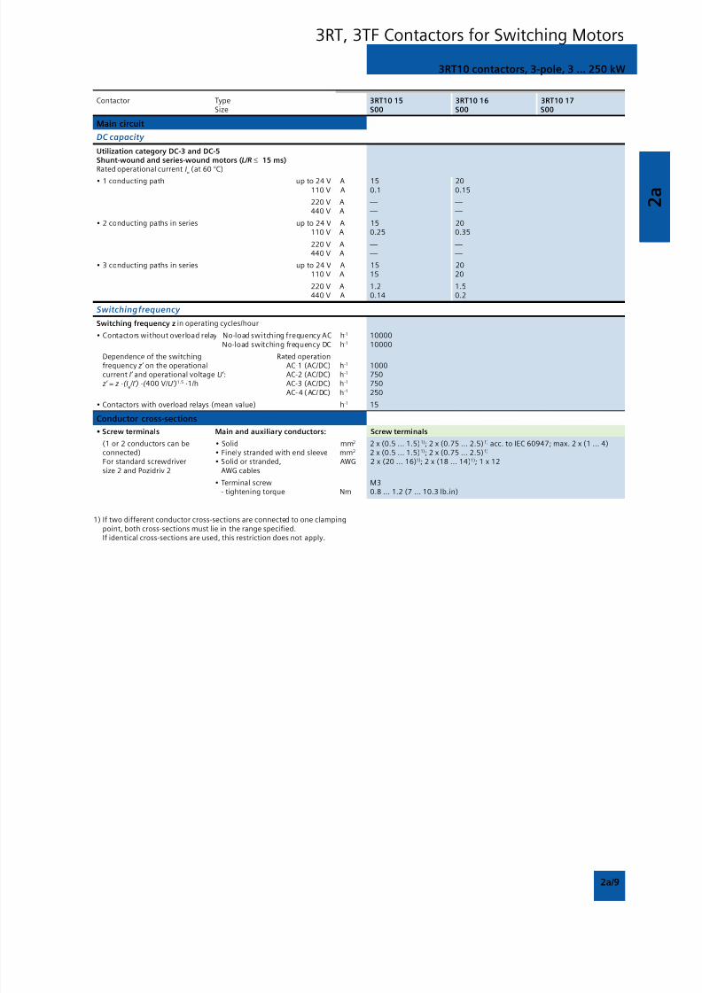
8/12/2019 SIRIUS Datasheet P-1
http://slidepdf.com/reader/full/sirius-datasheet-p-1 85/100
2 a
2a/9
3RT10 contactors, 3-pole, 3 ... 250 kW
3RT, 3TF Contactors for Switching Motors
Contactor Type 3RT10 15 3RT10 16 3RT10 17 Size S00 S00 S00
Main circuit
DC capacity
Utilization category DC-3 and DC-5Shunt-wound and series-wound motors (L/R ≤ 15 ms)Rated operational current I
e
(at 60 °C)
• 1 conducting path up to 24 V A 15 20 110 V A 0.1 0.15
220 V A — — 440 V A — —
• 2 conducting paths in series up to 24 V A 15 20 110 V A 0.25 0.35
220 V A — — 440 V A — —
• 3 conducting paths in series up to 24 V A 15 20 110 V A 15 20
220 V A 1.2 1.5 440 V A 0.14 0.2
Switching frequency
Switching frequency z in operating cycles/hour
• Contactors without overload relay No-load switching frequency AC h-1 10000
No-load switching frequency DC h-1
10000Dependence of the switching Rated operationfrequency z’ on the operational AC-1 (AC/DC) h-1 1000current I’ and operational voltage U’ : AC-2 (AC/DC) h-1 750 z’ = z ·(I
e /I’) ·( 400 V/U’)1.5 ·1/h AC-3 (AC/DC) h-1 750
AC-4 (AC/ DC) h-1 250
• Contactors with overload relays (mean value) h-1 15
Conductor cross-sections
• Screw terminals Main and auxiliary conductors: Screw terminals
(1 or 2 conductors can be • Solid mm2 2 x (0.5 ... 1.5)1); 2 x (0.75 ... 2.5)1) acc. to IEC 60947; max. 2 x (1 ... 4)connected) • Finely stranded with end sleeve mm2 2 x (0.5 ... 1.5)1); 2 x (0.75 ... 2.5)1)
For standard screwdriver • Solid or stranded, AWG 2 x (20 ... 16)1); 2 x (18 ... 14)1); 1 x 12size 2 and Pozidriv 2 AWG cables
• Terminal screw M3- tightening torque Nm 0.8 ... 1.2 (7 ... 10.3 lb.in)
1) If two different conductor cross-sections are connected to one clampingpoint, both cross-sections must lie in the range specified.If identical cross-sections are used, this restriction does not apply.

8/12/2019 SIRIUS Datasheet P-1
http://slidepdf.com/reader/full/sirius-datasheet-p-1 86/100
2 a
2a/10
3RT10 contactors, 3-pole, 3 ... 250 kW
3RT, 3TF Contactors for Switching Motors
Contactor Type 3RT10 23 3RT10 24 3RT10 25 3RT10 26Size S0 S0 S0 S0
General data
Permissible mounting position AC and DC operationThe contactors are designed foroperation on a vertical mountingsurface.
Mechanical endurance Basic unit Opera- 10 milliontingcycles
Basic unit with snap-on 10 millionauxiliary switch block
Electrical endurance 1)
Rated insulation voltage Ui (degree of pollution 3) V 690
Rated impulse withstand voltage Uimp
kV 6
Safe isolation between the coil and the main contacts V 400(acc. to EN 60947-1, Appendix N)
Mirror contacts• A mirror contact is an auxiliary 3RT10 2 . , 3RT13 2 . Yes, acc. to EN 60947-4-1, Appendix F
NC contact that cannot be (removable auxil iary switch block)closed simultaneously with aNO main contact.
Permissible ambient temperature During operation °C -25 ... +60
During storage °C -55 ... +80
Degree of protection acc. to EN 60947-1, Appendix C IP20, coil assembly IP20Touch protection acc. to EN 50274 Finger-safe
Shock resistance rectangular pulse AC operation g/ ms 8 .2/ 5 and 4 .9/ 10DC operation g/ms 10/5 and 7.5/10
Shock resistance sine pulse AC operation g/ ms 1 2.5 /5 and 7 .8/ 10DC operation g/ms 15/5 and 10/10
Conductor cross-sections 2)
Short-circuit protection for contactors without overload relays
Main circuit For short-circuit protection for contactors with overload relays seeProtection Equipment: Overload Relays
• Fuse links gL/gG For short-circuit protection for fuseless load feeders see Load Feeders,LV HRC 3NA, DIAZED 5SB, NEOZED 5SE Motor Starters and Soft Starters: -> 3RA Fuseless Load Feeders.- acc. to IEC 60947-4-1/ Type of coordination “1” A 63 100
EN 60947-4-1 Type of coordination “2” A 25 35Weld-free3) A 10 16
• Miniature circuit breakers with C characteristic A 25 32(short-circuit current 3 kA, type of coordination “1”)
Auxiliary circuit
• Fuse links gL/gG A 10DIAZED 5SB, NEOZED 5SE(weld-free protection at I
k≥ 1 kA)
• Miniature circuit breaker with C characteristic A 10(short-circuit current I
k < 400 A)
1) For endurance of the main contacts see page 2a/4.
2) For conductor cross-sections see page 2a/13.
3) Test conditions according to IEC 60947-4-1.
Contactor Type 3RT10 2 . Size S0
Control
Magnetic coil operating range AC/DC 0.8 ... 1.1 x Us
Power consumption of the magnetic coils (when coil is cold and 1.0 x Us)
AC operation, 50 Hz, • Closing VA 61standard version • P.f. 0.82
• Closed VA 7.8• P.f. 0.24
AC operation, 50/60 Hz, • Closing VA 64/63standard version • P.f. 0.72/0.74
• Closed VA 8.4/6.8• P.f. 0.24/0.28
DC operation Closing = Closed W 5.4
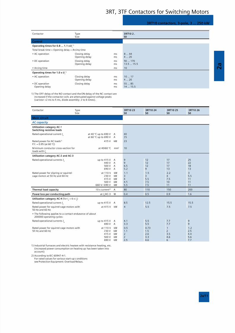
8/12/2019 SIRIUS Datasheet P-1
http://slidepdf.com/reader/full/sirius-datasheet-p-1 87/100

8/12/2019 SIRIUS Datasheet P-1
http://slidepdf.com/reader/full/sirius-datasheet-p-1 88/100
2 a
2a/12
3RT10 contactors, 3-pole, 3 ... 250 kW
3RT, 3TF Contactors for Switching Motors
Contactor Type 3RT10 23 3RT10 24 3RT10 25 3RT10 26 Size S0 S0 S0 S0
Main circuit
AC capacity
Utilization category AC-5aSwitching gas discharge lamps, inductive ballastPer main current path at 230 V1)
Rated po wer per lamp/rated operational current per lamp
Uncorrected L 18 W/0.37 A Units 108L 36 W/0.43 A Units 93L 58 W/0.67 A Units 59L 80 W/0.79 A Units 50
DUO switching (two-lamp) L 18 W/0.22 A Units 181 ( 2 x 181 lamps)L 36 W/0.42 A Units 95 ( 2 x 95 lamps )L 58 W/0.63 A Units 63 ( 2 x 63 lamps)L 80 W/0.87 A Units 45 ( 2 x 45 lamps)
Switching gas discharge lamps with correctionPer main current path at 230 V
Rated power per lamp/capacitance/rated operational current per lamp
• Shunt compensation with inductive L 18 W/4.5 µF/0.11 A Units 37 41 61ballast L 36 W/4.5 µF/0.21 A Units 30 30 51
L 58 W/7.0 µF/0.32 A Units 20 20 33L 80 W/7.0 µF/0.49 A Units 13 13 22
• With solid-state ballast2)
single lamp L 18 W/6.8 µF/0.10 A Units 105 119 175 L 36 W/6.8 µF/0.18 A Units 58 66 97L 58 W/10 µF/0.29 A Units 36 41 60L 80 W/10 µF/0.43 A Units 24 27 40
• With solid-state ballast2) two-lamp L 18 W/10 µF/0.18 A Units 58 ( 2 x 58 lamps) 66 ( 2 x 66 l.) 97 ( 2 x 97 l.) L 36 W/10 µF/0.35 A Units 30 ( 2 x 30 lamps) 34 ( 2 x 34 l.) 50 ( 2 x 50 l.)
L 58 W/22 µF/0.52 A Units 20 ( 2 x 20 lamps) 22 ( 2 x 22 l.) 33 ( 2 x 33 l.)L 80 W/22 µF/0.86 A Units 12 ( 2 x 12 lamps) 13 ( 2 x 13 l.) 20 ( 2 x 20 l.)
Utilization category AC-5b, switching incandescent lamps kW 2.8 3.2 4.7Per main current path at 230/220 V
Utilization category AC-6aswitching AC transformers
Rated operational current Ie
• For inrush current n = 20 up to 415 V A 11.4 20.2• For inrush current n = 30 up to 415 V A 7.6 13.5
Rating P
• For inrush current n = 20 415 V kVA 7.9 13.9
• For inrush current n = 30 415 V kVA 5.2 9.3
For deviating inrush current factors x, the power must be recalculated as follows:P
x = P
n30 · 30/x
Utilization category AC-6b,switching low-inductance (low-loss, metallized dielectric) AC capacitors
Rated operational currents Ie
up to 415 V A 5.8 10.8
Rated power for single capacitors or at 230 V kvar 2.5 4banks of capacitors (minimum inductance 400 V kvar 4 7.5of 6 H between capacitors connected 500 V kvar 4 7.5in parallel) at 50 Hz, 60 Hz and 690 V kvar 4 7.5
DC capacity
Utilization category DC-1Switching resistive loads (L/R ≤≤≤≤≤ 1ms)
Rated operational current Ie (at 6 0 °C)
• 1 conducting path up to 24 V A 35110 V A 4.5
220 V A 1440 V A 0.4
• 2 conducting paths in series up to 24 V A 35110 V A 35
220 V A 5440 V A 1
• 3 conducting paths in series up to 24 V A 35110 V A 35
220 V A 35440 V A 2.9
1) For Ie/AC-1 = 35 A (60 °C) and the corresponding minimum conductor
cross-section 10 mm2.
2) Depending on the electronic ballast used, higher lamp numbers are alsopossible.

8/12/2019 SIRIUS Datasheet P-1
http://slidepdf.com/reader/full/sirius-datasheet-p-1 89/100
2 a
2a/13
3RT10 contactors, 3-pole, 3 ... 250 kW
3RT, 3TF Contactors for Switching Motors
Contactor Type 3RT10 23 3RT10 24 3RT10 25 3RT10 26 Size S0 S0 S0 S0
Main circuit
Utilization category DC-3 and DC-5Shunt-wound and series-wound motors (L/R ≤≤≤≤≤ 15 ms)Rated operational current I
e (at 60 °C)
• 1 conducting path up to 24 V A 20
110 V A 2.5
220 V A 1440 V A 0.09
• 2 conducting paths in series up to 24 V A 35110 V A 15
220 V A 3440 V A 0.27
• 3 conducting paths in series up to 24 V A 35110 V A 35
220 V A 10440 V A 0.6
Switching frequency
Switching frequency z in operating cycles/hour
• Contactors without overload relays No-load switching h-1 5000frequency AC
Dependence of the switching frequency z’ No-load switching h-1 1500
on the operational current I’ and operational frequency DCvoltage U’ : z’ = z ·(I
e /I’) ·( 400 V/U’)1.5 ·1/h AC-1 (AC/DC) h-1 1000
AC-2 (AC/ DC) h-1 1000 750AC-3 (AC/ DC) h-1 1000 750AC-4 (AC/ DC) h-1 300 250
• Contactors with overload relays (mean value) h-1 15
Conductor cross-sections
Screw terminals Main conductors Screw terminals
(1 or 2 conductors can be Conductor cross -sectionconnected) • Solid mm² 2 x (1 ... 2.5)1); 2 x (2.5 ... 6)1) acc. to IEC 60947; max. 1 x 10
• Finely stranded with end sleeve mm² 2 x (1 ... 2.5)1); 2 x (2.5 ... 6)1)
• AWG cables, solid AWG 2 x (16 ... 12)• AWG cables, AWG 2 x (14 ... 10)
solid or stranded• AWG cables, stranded AWG 1 x 8• Terminal screws M4 (Pozidriv size 2)
- tightening torque Nm 2 ... 2.5 (18 ... 22 lb.in)
Auxiliary conductors
Conductor cross-section• Solid mm2 2 x (0.5 ... 1.5)1); 2 x (0.75 ... 2.5)1) 0.75) acc. to IEC 60947;
max. 2 x (0.75 ... 4)• Finely stranded with end sleeve mm2 2 x (0.5 ... 1.5)1); 2 x (0.75 ... 2.5)1)
• Solid or stranded AWG (2 x) AWG 2 x (20 ... 16)1); 2 x (18 ... 14)1); 1 x 12• Terminal screws M3
- tightening torque Nm 0.8 ... 1.2 (7 ... 10.3 lb.in)
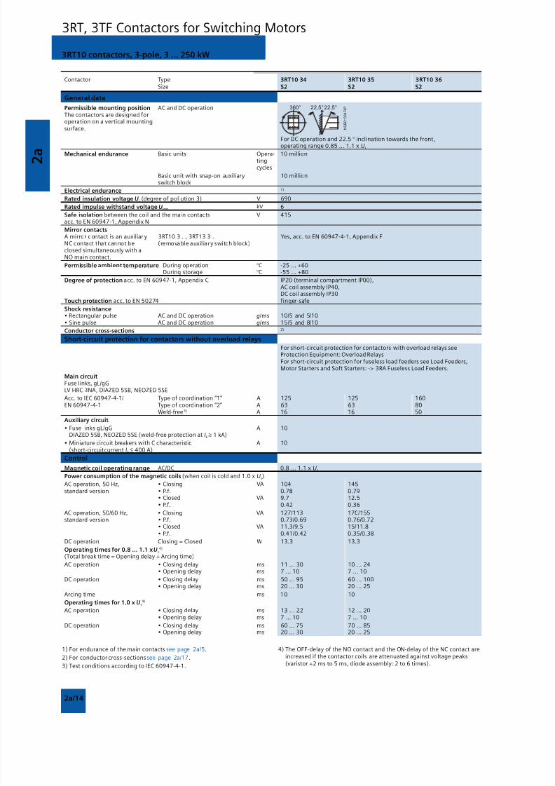
8/12/2019 SIRIUS Datasheet P-1
http://slidepdf.com/reader/full/sirius-datasheet-p-1 90/100
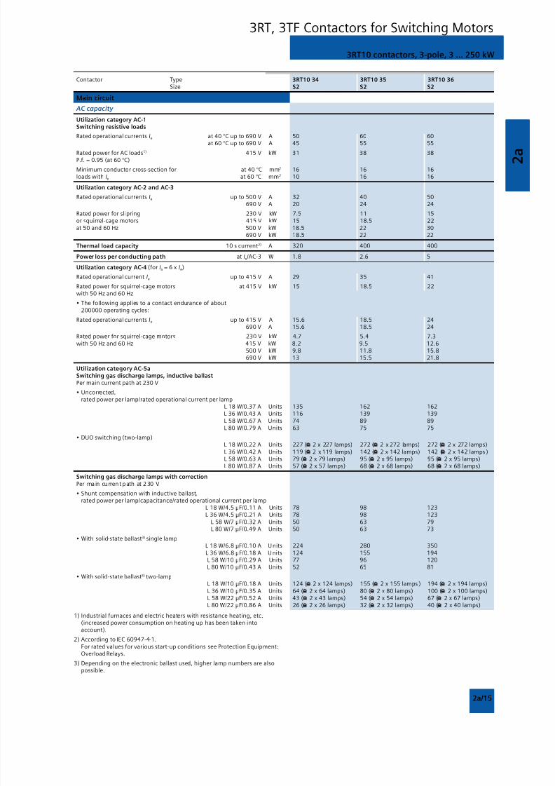
8/12/2019 SIRIUS Datasheet P-1
http://slidepdf.com/reader/full/sirius-datasheet-p-1 91/100
2 a
2a/15
3RT10 contactors, 3-pole, 3 ... 250 kW
3RT, 3TF Contactors for Switching Motors
Contactor Type 3RT10 34 3RT10 35 3RT10 36 Size S2 S2 S2
Main circuit
AC capacity
Utilization category AC-1Switching resistive loads
Rated operational currents Ie at 40 °C up to 690 V A 50 60 60at 60 °C up to 690 V A 45 55 55
Rated power for AC loads1) 415 V kW 31 38 38P.f. = 0.95 (at 60 °C)
Minimum conductor cross-section for at 40 °C mm2 16 16 16loads with Ie at 60 °C mm2 10 16 16
Utilization category AC-2 and AC-3
Rated operational currents Ie up to 500 V A 32 40 50 690 V A 20 24 24
Rated power for slipring 230 V kW 7.5 11 15or squirrel-cage motors 415 V kW 15 18.5 22at 50 and 60 Hz 500 V kW 18.5 22 30
690 V kW 18.5 22 22
Thermal load capacity 10 s current2) A 320 400 400
Power loss per conducting path at Ie/AC-3 W 1.8 2.6 5
Utilization category AC-4 (for Ia = 6 x Ie)
Rated operational current Ie up to 415 V A 29 35 41
Rated power for squirrel-cage motors at 415 V kW 15 18.5 22with 50 Hz and 60 Hz
• The following applies to a contact endurance of about200000 operating cycles:
Rated operational currents Ie up to 415 V A 15.6 18.5 24690 V A 15.6 18.5 24
Rated power for squirrel-cage motors 230 V kW 4.7 5.4 7.3with 50 Hz and 60 Hz 415 V kW 8.2 9.5 12.6
500 V kW 9.8 11.8 15.8690 V kW 13 15.5 21.8
Utilization category AC-5aSwitching gas discharge lamps, inductive ballastPer main current path at 230 V
• Uncorrected,rated power per lamp/rated operational current per lamp
L 18 W/0.37 A Units 135 162 162
L 36 W/0.43 A Units 116 139 139L 58 W/0.67 A Units 74 89 89L 80 W/0.79 A Units 63 75 75
• DUO switching (two-lamp)L 18 W/0.22 A Units 227 ( 2 x 227 lamps) 272 ( 2 x 272 lamps) 272 ( 2 x 272 lamps)L 36 W/0.42 A Units 119 ( 2 x 119 lamps) 142 ( 2 x 142 lamps) 142 ( 2 x 142 lamps )
L 58 W/0.63 A Units 79 ( 2 x 79 lamps) 95 ( 2 x 95 lamps) 95 ( 2 x 95 lamps)L 80 W/0.87 A Units 57 ( 2 x 57 lamps) 68 ( 2 x 68 lamps) 68 ( 2 x 68 lamps)
Switching gas discharge lamps with correctionPer ma in cu rrent path at 2 30 V
• Shunt compensation with inductive ballast,rated power per lamp/capacitance/rated operational current per lamp
L 18 W/4.5 F/0.11 A Units 78 98 123 L 36 W/4.5 F/0.21 A Units 78 98 123
L 58 W/7 F/0.32 A Units 50 63 79L 80 W/7 F/0.49 A Units 50 63 73
• With solid-state ballast3) single lamp L 18 W/6.8 F/0.10 A Units 224 280 350
L 36 W/6.8 F/0.18 A Units 124 155 194L 58 W/10 F/0.29 A Units 77 96 120L 80 W/10 F/0.43 A Units 52 65 81
• With solid-state ballast3) two-lampL 18 W/10 F/0.18 A Units 124 ( 2 x 124 lamps) 155 ( 2 x 155 lamps ) 194 ( 2 x 194 lamps)
L 36 W/10 F/0.35 A Units 64 ( 2 x 64 lamps) 80 ( 2 x 80 lamps) 100 ( 2 x 100 lamps)L 58 W/22 F/0.52 A Units 43 ( 2 x 43 lamps) 54 ( 2 x 54 lamps) 67 ( 2 x 67 lamps)L 80 W/22 F/0.86 A Units 26 ( 2 x 26 lamps) 32 ( 2 x 32 lamps) 40 ( 2 x 40 lamps)
1) Industrial furnaces and electric heaters with resistance heating, etc.(increased power consumption on heating up has been taken intoaccount).
2) According to IEC 60947-4-1.For rated values for various start-up conditions see Protection Equipment:Overload Relays.
3) Depending on the electronic ballast used, higher lamp numbers are alsopossible.
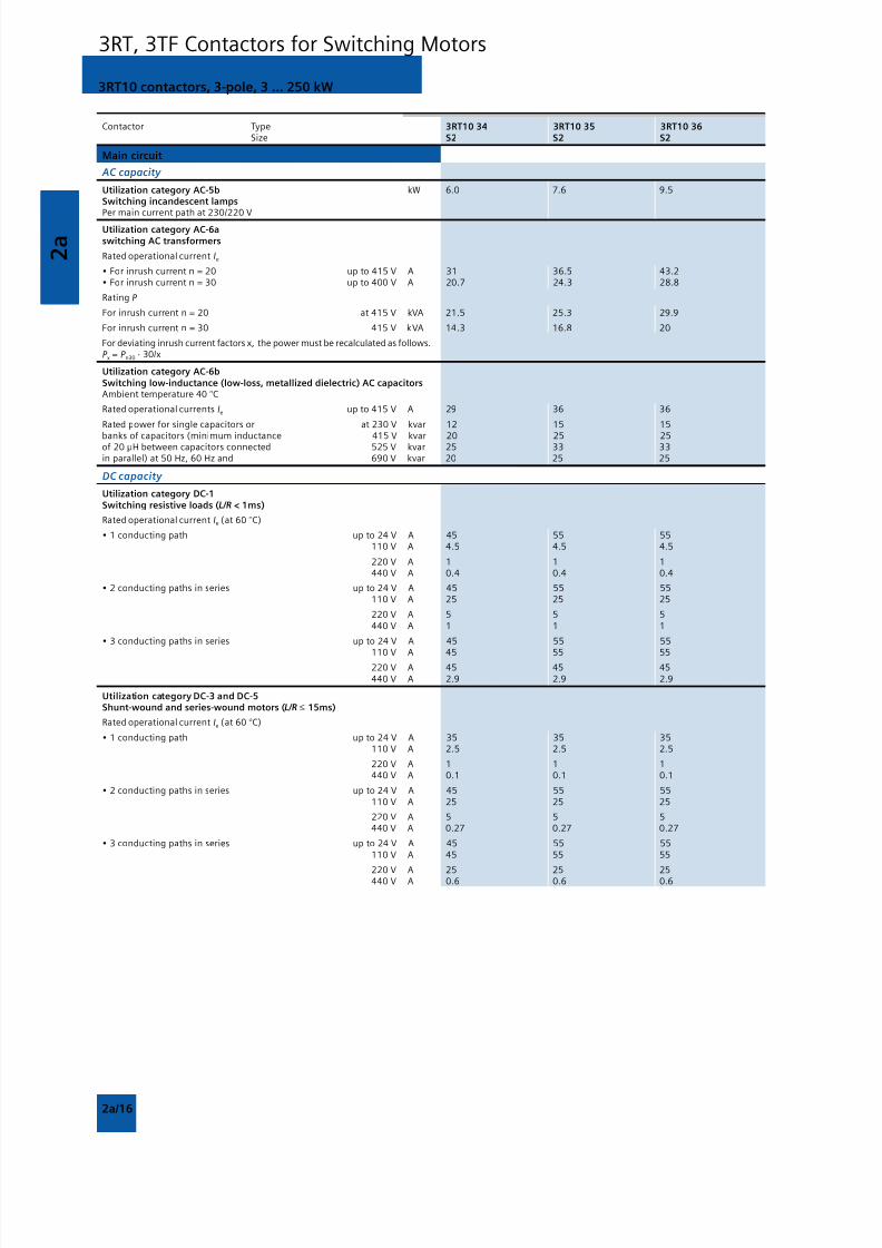
8/12/2019 SIRIUS Datasheet P-1
http://slidepdf.com/reader/full/sirius-datasheet-p-1 92/100
2 a
2a/16
3RT10 contactors, 3-pole, 3 ... 250 kW
3RT, 3TF Contactors for Switching Motors
Contactor Type 3RT10 34 3RT10 35 3RT10 36 Size S2 S2 S2
Main circuit
AC capacity
Utilization category AC-5b kW 6.0 7.6 9.5Switching incandescent lampsPer main current path at 230/220 V
Utilization category AC-6aswitching AC transformers
Rated operational current Ie
• For inrush current n = 20 up to 415 V A 31 36.5 43.2• For inrush current n = 30 up to 400 V A 20.7 24.3 28.8
Rating P
For inrush current n = 20 at 415 V kVA 21.5 25.3 29.9
For inrush current n = 30 415 V kVA 14.3 16.8 20
For deviating inrush current factors x, the power must be recalculated as follows.P x = P n30 · 30/x
Utilization category AC-6bSwitching low-inductance (low-loss, metallized dielectric) AC capacitorsAmbient temperature 40 °C
Rated operational currents Ie up to 415 V A 29 36 36
Rated power for single capacitors or at 230 V kvar 12 15 15
banks of capacitors (minimum inductance 415 V kvar 20 25 25of 20 H between capacitors connected 525 V kvar 25 33 33in parallel) at 50 Hz, 60 Hz and 690 V kvar 20 25 25
DC capacity
Utilization category DC-1Switching resistive loads (L/R < 1ms)
Rated operational current Ie (at 60 °C)
• 1 conducting path up to 24 V A 45 55 55110 V A 4.5 4.5 4.5
220 V A 1 1 1440 V A 0.4 0.4 0.4
• 2 conducting paths in series up to 24 V A 45 55 55110 V A 25 25 25
220 V A 5 5 5440 V A 1 1 1
• 3 conducting paths in series up to 24 V A 45 55 55
110 V A 45 55 55220 V A 45 45 45440 V A 2.9 2.9 2.9
Utilization category DC-3 and DC-5Shunt-wound and series-wound motors (L/R ≤ 15ms)
Rated operational current Ie (at 60 °C)
• 1 conducting path up to 24 V A 35 35 35110 V A 2.5 2.5 2.5
220 V A 1 1 1440 V A 0.1 0.1 0.1
• 2 conducting paths in series up to 24 V A 45 55 55110 V A 25 25 25
220 V A 5 5 5440 V A 0.27 0.27 0.27
• 3 conducting paths in series up to 24 V A 45 55 55110 V A 45 55 55
220 V A 25 25 25440 V A 0.6 0.6 0.6
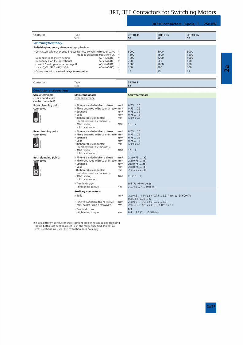
8/12/2019 SIRIUS Datasheet P-1
http://slidepdf.com/reader/full/sirius-datasheet-p-1 93/100
2 a
2a/17
3RT10 contactors, 3-pole, 3 ... 250 kW
3RT, 3TF Contactors for Switching Motors
Contactor Type 3RT10 34 3RT10 35 3RT10 36 Size S2 S2 S2
Switching frequency
Switching frequency z in operating cycles/hour
• Contactors without overload relays No-load switching frequency AC h-1 5000 5000 5000No-load switching frequency DC h-1 1500 1500 1500
Dependence of the switching AC-1 (AC/DC) h-1 1200 1200 1000
frequency z’ on the operational AC-2 (AC/DC) h-1 750 600 400current I’ and operational voltage U’: AC-3 (AC/DC) h-1 1000 1000 800 z’ = z ·(I
e /I’) ·( 400 V/U’)1.5 ·1/h AC-4 (AC/DC) h-1 250 300 300
• Contactors with overload relays (mean value) h-1 15 15 15
Contactor Type 3RT10 3 . Size S2
Conductor cross-sections
Screw terminals Main conductors: Screw terminals(1 or 2 conductors with box terminalcan be connected)
Front clamping point • Finely stranded with end sleeve mm² 0.75 . .. 25
connected • Finely stranded without end sleeve mm² 0.75 ... 25• Stranded mm² 0.75 ... 35• Solid mm² 0.75 ... 16• Ribbon cable conductors mm 6 x 9 x 0.8
(number x width x thickness)• AWG cables, AWG 18 ... 2
solid or stranded
Rear clamping point • Finely stranded with end sleeve mm² 0.75 . .. 25
connected • Finely stranded without end sleeve mm² 0.75 ... 25• Stranded mm² 0.75 ... 35• Solid mm² 0.75 ... 16• Ribbon cable conductors mm 6 x 9 x 0.8
(number x width x thickness)• AWG cables, AWG 18 ... 2
solid or stranded
Both clamping points • Finely stranded with end sleeve mm² 2 x (0.75 .. . 16)connected • Finely stranded without end sleeve mm² 2 x (0.75 ... 16)
• Stranded mm² 2 x (0.75 ... 25)• Solid mm² 2 x (0.75 ... 16)• R ibbon cable conductors mm 2 x (6 x 9 x 0.8)
(number x width x thickness)• AWG cables, AWG 2 x (18 ... 2)
solid or stranded
• Terminal screw M6 (Pozidriv size 2)- tightening torque Nm 3 ... 4.5 (27 ... 40 lb.in)
Auxiliary conductors:
• Solid mm² 2 x (0.5 ... 1.5)1); 2 x (0.75 ... 2.5)1) acc. to IEC 60947;max. 2 x (0.75 ... 4)
• Finely stranded with end sleeve mm² 2 x (0.5 . .. 1.5)1); 2 x (0.75 ... 2.5)1)
• AWG cab les , solid or s tranded AWG 2 x (20 .. . 1 6)1); 2 x (18 ... 14)1); 1 x 12
• Terminal screw M3- tightening torque Nm 0.8 ... 1.2 (7 ... 10.3 lb.in)
1) If two different conductor cross-sections are connected to one clampingpoint, both cross-sections must lie in the range specified. If identicalcross-sections are used, this restriction does not apply.
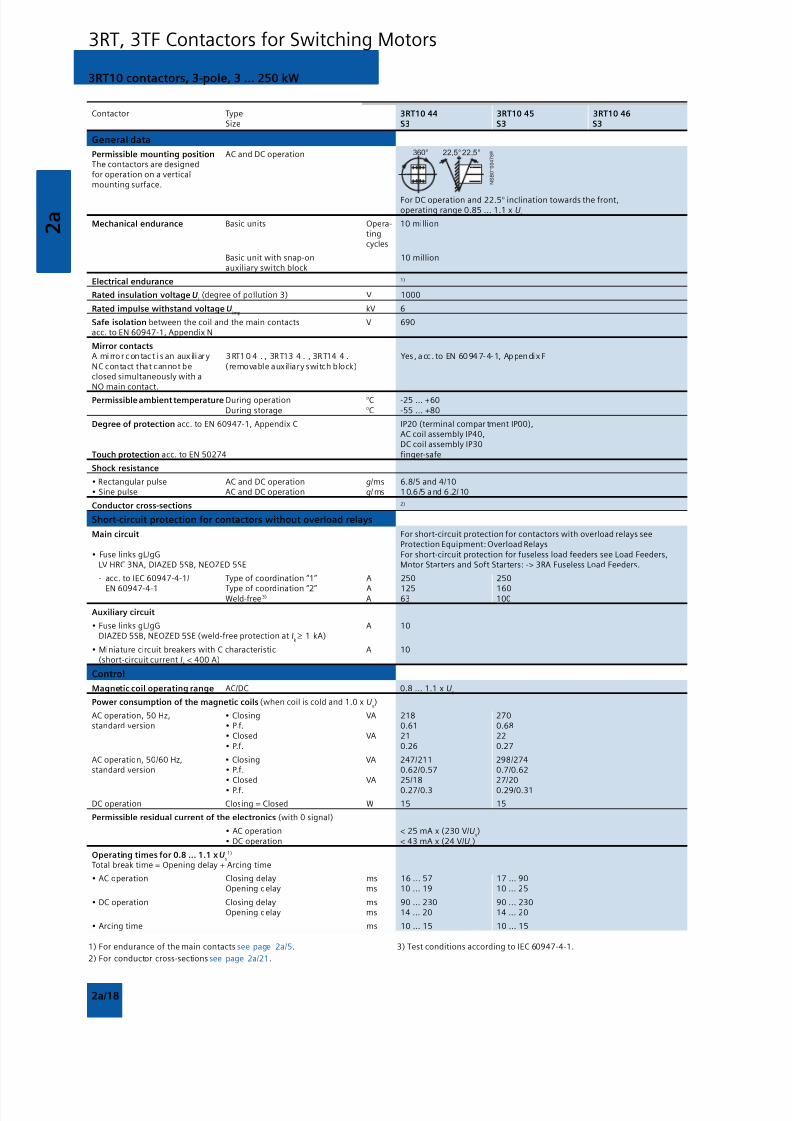
8/12/2019 SIRIUS Datasheet P-1
http://slidepdf.com/reader/full/sirius-datasheet-p-1 94/100
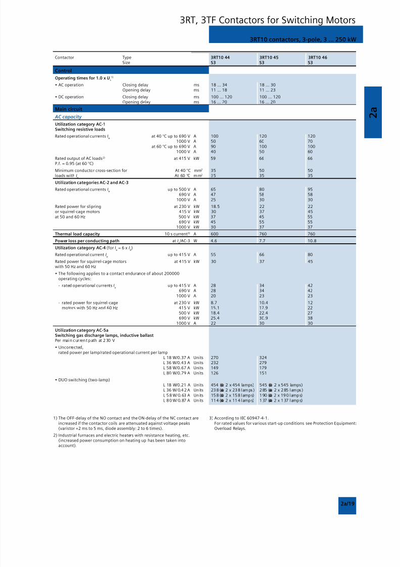
8/12/2019 SIRIUS Datasheet P-1
http://slidepdf.com/reader/full/sirius-datasheet-p-1 95/100
2 a
2a/19
3RT10 contactors, 3-pole, 3 ... 250 kW
3RT, 3TF Contactors for Switching Motors
Contactor Type 3RT10 44 3RT10 45 3RT10 46 Size S3 S3 S3
Control
Operating times for 1.0 x Us1)
• AC operation Closing delay ms 18 ... 34 18 ... 30Opening delay ms 11 ... 18 11 ... 23
• DC operation Closing delay ms 100 ... 120 100 ... 120Opening delay ms 16 ... 20 16 ... 20
Main circuit
AC capacity
Utilization category AC-1Switching resistive loads
Rated operational currents Ie
at 40 °C up to 690 V A 100 120 1201000 V A 50 60 70
at 60 °C up to 690 V A 90 100 1001000 V A 40 50 60
Rated output of AC loads2) at 415 V kW 59 66 66P.f. = 0.95 (at 60 °C)
Minimum conductor cross-section for At 40 °C mm2 35 50 50loads with I
eAt 60 °C mm2 35 35 35
Utilization categories AC-2 and AC-3
Rated operational currents Ie
up to 500 V A 65 80 95690 V A 47 58 58
1000 V A 25 30 30
Rated power for slipring at 230 V kW 18.5 22 22or squirrel-cage motors 415 V kW 30 37 45at 50 and 60 Hz 500 V kW 37 45 55
690 V kW 45 55 551000 V kW 30 37 37
Thermal load capacity 10 s current3) A 600 760 760
Power loss per conducting path at Ie/AC-3 W 4.6 7.7 10.8
Utilization category AC-4 (for Ia = 6 x I
e)
Rated operational current Ie
up to 415 V A 55 66 80
Rated power for squirrel-cage motors at 415 V kW 30 37 45with 50 Hz and 60 Hz
• The following applies to a contact endurance of about 200000operating cycles:
- rated operational currents Ie
up to 415 V A 28 34 42690 V A 28 34 42
1000 V A 20 23 23- rated power for squirrel-cage at 230 V kW 8.7 10.4 12
motors with 50 Hz and 60 Hz 415 V kW 15.1 17.9 22500 V kW 18.4 22.4 27690 V kW 25.4 30.9 38
1000 V A 22 30 30
Utilization category AC-5aSwitching gas discharge lamps, inductive ballastPer main cur rent path at 2 30 V
• Uncorrected,rated power per lamp/rated operational current per lamp
L 18 W/0.37 A Units 270 324L 36 W/0.43 A Units 232 279L 58 W/0.67 A Units 149 179L 80 W/0.79 A Units 126 151
• DUO switching (two-lamp)L 18 W/0.21 A Units 454 ( 2 x 454 lamps) 545 ( 2 x 545 lamps)L 36 W/ 0.4 2 A Units 23 8 ( 2 x 23 8 lamps) 2 85 ( 2 x 2 85 lamps)
L 5 8 W/ 0.63 A Units 15 8 ( 2 x 15 8 lamps) 1 90 ( 2 x 19 0 lamps)L 8 0 W/ 0.87 A Units 11 4 ( 2 x 11 4 lamps) 1 37 ( 2 x 1 37 lamps)
1) The OFF-delay of the NO contact and the ON-delay of the NC contact areincreased if the contactor coils are attenuated against voltage peaks(varistor +2 ms to 5 ms, diode assembly: 2 to 6 times).
2) Industrial furnaces and electric heaters with resistance heating, etc.(increased power consumption on heating up has been taken intoaccount).
3) According to IEC 60947-4-1.For rated values for various start-up conditions see Protection Equipment:Overload Relays.
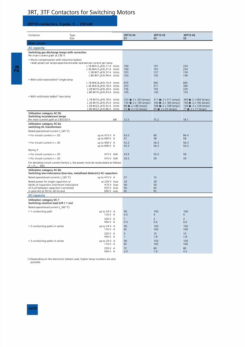
8/12/2019 SIRIUS Datasheet P-1
http://slidepdf.com/reader/full/sirius-datasheet-p-1 96/100
2 a
2a/20
3RT10 contactors, 3-pole, 3 ... 250 kW
3RT, 3TF Contactors for Switching Motors
Contactor Type 3RT10 44 3RT10 45 3RT10 46 Size S3 S3 S3
Main circuit
AC capacity
Switching gas discharge lamps with correctionPe r main cur rent path at 2 30 V
• Shunt compensation with inductive ballast,rated power per lamp/capacitance/rated operational current per lampL 18 W/4.5 F/0.11 A Units 160 197 234L 36 W/4.5 F/0.21 A Units 160 197 234
L 58 W/7 F/0.32 A Units 103 127 150L 80 W/7 F/0.49 A Units 103 126 146
• With solid-state ballast1) single lampL 18 W/6.8 F/0.10 A Units 455 560 665L 36 W/6.8 F/0.18 A Units 253 311 369L 58 W/10 F/0.29 A Units 156 193 229L 80 W/10 F/0.43 A Units 105 130 154
• With solid-state ballast1) two-lampL 18 W/10 F/0.18 A Units 253 ( 2 x 253 lamps) 311 ( 2 x 311 lamps) 369 ( 2 x 369 lamps )L 36 W/10 F/0.35 A Units 130 ( 2 x 130 lamps ) 160 ( 2 x 160 lamps) 190 ( 2 x 190 lamps)L 58 W/22 F/0.52 A Units 88 ( 2 x 88 lamps) 108 ( 2 x 10⁸ lamps) 128 ( 2 x 128 lamps)L 80 W/22 F/0.86 A Units 52 ( 2 x 52 lamps) 65 ( 2 x 65 lamps) 77 ( 2 x 77 lamps)
Utilization category AC-5bSwitching incandescent lampsPer main current path at 230/220 V kW 12.3 15.2 18.1
Utilization category AC-6aswitching AC transformers
Rated operational current Ie (60 °C)
• For inrush current n = 20 up to 415 V A 63.5 80 84.4up to 690 V A 47 58 58
• For inrush current n = 30 up to 400 V A 42.3 56.3 56.3up to 690 V A 42.3 56.3 56.3
Rating P
• For inrush current n = 20 415 V kVA 43.9 55.4 58
• For inrush current n = 30 415 V kVA 29.3 39 39
For deviating inrush current factors x, the power must be recalculated as follows.P
x = P
n30 · 30/x
Utilization category AC-6bSwitching low-inductance (low-loss, metallized dielectric) AC capacitors
Rated operational currents Ie (60 °C) up to 415 V A 57 72
Rated power for single capacitors or at 230 V kvar 24 29banks of capacitors (minimum inductance 415 V kvar 40 50of 6 H between capacitors connected 525 V kvar 50 65in parallel) at 50 Hz, 60 Hz and 690 V kvar 40 50
DC capacity
Utilization category DC-1Switching resistive load (L/R £ 1 ms)
Rated operational current Ie (60 °C)
• 1 conducting path up to 24 V A 90 100 100110 V A 4.5 9 9
220 V A 1 2 2440 V A 0.4 0.6 0.6
• 2 conducting paths in series up to 24 V A 90 100 100110 V A 90 100 100
220 V A 5 10 10440 V A 1 1.8 1.8
• 3 conducting paths in series up to 24 V A 90 100 100
110 V A 90 100 100
220 V A 70 80 80440 V A 2.9 1.8 4.5
1) Depending on the electronic ballast used, higher lamp numbers are alsopossible.
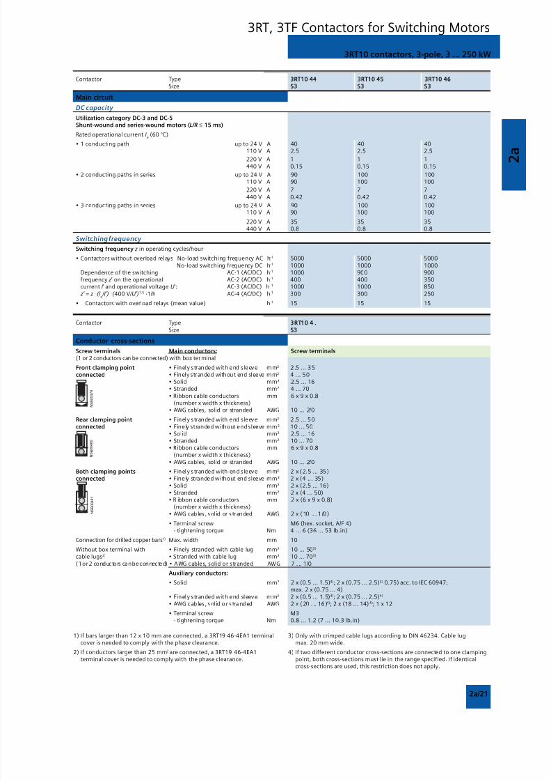
8/12/2019 SIRIUS Datasheet P-1
http://slidepdf.com/reader/full/sirius-datasheet-p-1 97/100
2 a
2a/21
3RT10 contactors, 3-pole, 3 ... 250 kW
3RT, 3TF Contactors for Switching Motors
Contactor Type 3RT10 44 3RT10 45 3RT10 46 Size S3 S3 S3
Main circuit
DC capacity
Utilization category DC-3 and DC-5Shunt-wound and series-wound motors (L/R ≤ 15 ms)
Rated operational current Ie (60 °C)• 1 conducting path up to 24 V A 40 40 40
110 V A 2.5 2.5 2.5
220 V A 1 1 1440 V A 0.15 0.15 0.15
• 2 conducting paths in series up to 24 V A 90 100 100110 V A 90 100 100
220 V A 7 7 7440 V A 0.42 0.42 0.42
• 3 conducting paths in series up to 24 V A 90 100 100110 V A 90 100 100
220 V A 35 35 35440 V A 0.8 0.8 0.8
Switching frequency
Switching frequency z in operating cycles/hour
• Contactors without overload relays No-load switching frequency AC h-1 5000 5000 5000No-load switching frequency DC h-1 1000 1000 1000
Dependence of the switching AC-1 (AC/DC) h-1
1000 900 900frequency z’ on the operational AC-2 (AC/DC) h-1 400 400 350current I’ and operational voltage U’: AC-3 (AC/DC) h -1 1000 1000 850 z’ = z ·(I
e /I’) ·( 400 V/U’)1.5 ·1/h AC-4 (AC/DC) h-1 300 300 250
• Contactors with overload relays (mean value) h-1 15 15 15
Contactor Type 3RT10 4 . Size S3
Conductor cross-sections
Screw terminals Main conductors: Screw terminals(1 or 2 conductors can be connected) with box terminal
Front clamping point • Finely stranded with end sleeve mm² 2.5 . .. 35connected • Finely stranded without end sleeve mm² 4 ... 50
• Solid mm² 2.5 ... 16• Stranded mm² 4 ... 70• Ribbon cable conductors mm 6 x 9 x 0.8
(number x width x thickness)
• AWG cables, solid or stranded AWG 10 ... 2/0Rear clamping point • Finely stranded with end sleeve mm² 2.5 . .. 50connected • Finely stranded without end sleeve mm² 10 ... 50
• Solid mm² 2.5 ... 16• Stranded mm² 10 ... 70• Ribbon cable conductors mm 6 x 9 x 0.8
(number x width x thickness)• AWG cables, solid or stranded AWG 10 ... 2/0
Both clamping points • Finely stranded with end sleeve mm² 2 x (2.5 . .. 35)connected • Finely stranded without end sleeve mm² 2 x (4 ... 35)
• Solid mm² 2 x (2.5 ... 16)• Stranded mm² 2 x (4 ... 50)• R ibbon cable conductors mm 2 x (6 x 9 x 0.8)
(number x width x thickness)• AWG cab les , sol id or s tranded AWG 2 x (10 .. . 1 /0 )
• Terminal screw M6 (hex. socket, A/F 4) - tightening torque Nm 4 ... 6 (36 ... 53 lb.in)
Connection for drilled copper bars1) Max. width mm 10
Without box terminal with • Finely stranded with cable lug mm² 10 ... 503)
cable lugs2) • Stranded with cable lug mm² 10 ... 703)
(1 or 2 conductors can be connected) • AWG cables, solid or stranded AWG 7 ... 1/0
Auxiliary conductors:
• Solid mm² 2 x (0.5 ... 1.5)4); 2 x (0.75 ... 2.5)4) 0.75) acc. to IEC 60947;max. 2 x (0.75 ... 4)
• Finely stranded with end sleeve mm² 2 x (0.5 . .. 1.5)4); 2 x (0.75 ... 2.5)4)
• AWG cab les , sol id or s tra nded AWG 2 x (20 . .. 16 )4); 2 x (18 ... 14) 4); 1 x 12
• Terminal screw M3 - tightening torque Nm 0.8 ... 1.2 (7 ... 10.3 lb.in)
1) If bars larger than 12 x 10 mm are connected, a 3RT19 46-4EA1 terminalcover is needed to comply with the phase clearance.
2) If conductors larger than 25 mm2 are connected, a 3RT19 46-4EA1terminal cover is needed to comply with the phase clearance.
3) Only with crimped cable lugs according to DIN 46234. Cable lugmax. 20 mm wide.
4) If two different conductor cross-sections are connected to one clampingpoint, both cross-sections must lie in the range specified. If identicalcross-sections are used, this restriction does not apply.
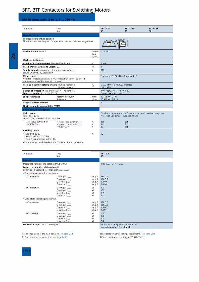
8/12/2019 SIRIUS Datasheet P-1
http://slidepdf.com/reader/full/sirius-datasheet-p-1 98/100
2 a
2a/22
3RT10 contactors, 3-pole, 3 ... 250 kW
3RT, 3TF Contactors for Switching Motors
Contactor Type 3RT10 54 3RT10 55 3RT10 56 Size S6 S6 S6
General data
Permissible mounting positionThe contactors are designed for operation on a vertical mounting surface.
Mechanical endurance Opera- 10 milliontingcycles
Electrical endurance 1)
Rated insulation voltage Ui (degree of pollution 3) V 1000
Rated impulse withstand voltage Uimp kV 8
Safe isolation between the coil and the main contacts V 690acc. to EN 60947-1, Appendix N
Mirror contacts Yes, acc. to EN 60947-4-1, Appendix FA mirror contact is an auxiliary NC contact that cannot be closedsimultaneously with a NO main contact.
Permissible ambient temperature During operation °C -25 ... +60/+55 with AS-InterfaceDuring storage °C -55 ... +80
Degree of protection acc. to EN 60947-1, Appendix C IP00/open, coil assembly IP20Touch protection acc. to EN 50274 Finger-safe with cover
Shock resistance Rectangular pulse g/ ms 8 .5/ 5 a nd 4 .2 /10
Sine pulse g/ ms 1 3.4 /5 and 6 .5/ 10
Conductor cross-sections 2)
Electromagnetic compatibility (EMC) 3)
Short-circuit protection
Main circuit For short-circuit protection for contactors with overload relays seeFuse links, gL/gG Protection Equipment: Overload RelaysLV HRC 3NA, DIAZED 5SB, NEOZED 5SE
- acc. to IEC 60947-4-1/ • Type of coordination “1” A 355 355EN 60947-4-1 • Type of coordination “2” A 315 315
• Weld-free4) A 80 160
Auxiliary circuit
• Fuse links gL/gG A 10DIAZED 5SB, NEOZED 5SE(weld-free protection at Ik ≥ 1 kA)
• Or miniature circuit breakers with C characteristic (Ik < 400 A)
Contactor Type 3RT10 5 . Size S6
Control
Operating range of the solenoid AC/DC (UC) 0.8 x Us min ... 1.1 x Us max
Power consumption of the solenoid(when coil is cool and rated range Us min ... Us max)
• Conventional operating mechanism
- AC operation Closing at Us min VA/p.f. 250/0.9 Closing at Us max VA/p.f. 300/0.9
Closed at Us min VA/p.f. 4.8/0.8 Closed at Us max VA/p.f. 5.8/0.8
- DC operation Closing at Us min W 300 Closing at Us max W 360 Closed at Us min W 4.3
Closed at Us max W 5.2
• Solid-state operating mechanism
- AC operation Closing at Us min VA/p.f. 190/0.8 Closing at Us max VA/p.f. 280/0.8 Closed at Us min VA/p.f. 3.5/0.5 Closed at Us max VA/p.f. 4.4/0.4
- DC operation Closing at Us min W 250 Closing at Us max W 320 Closed at Us min W 2.3 Closed at Us max W 2.8
PLC control input (EN 61131-2/type 2) 24 V DC/≤ 30 mA power consumption,(operating range 17 ... 30 V DC)
1) For endurance of the main contacts see page 2a/5.
2) For conductor cross-sections see page 2a/25.
3) For electromagnetic compatibility (EMC) see page 2/10.
4) Test conditions according to IEC 60947-4-1.
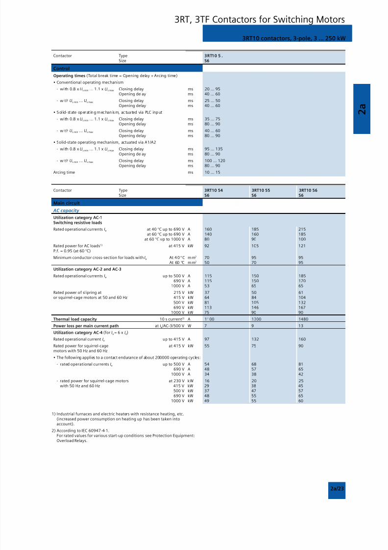
8/12/2019 SIRIUS Datasheet P-1
http://slidepdf.com/reader/full/sirius-datasheet-p-1 99/100
2 a
2a/23
3RT10 contactors, 3-pole, 3 ... 250 kW
3RT, 3TF Contactors for Switching Motors
Contactor Type 3RT10 5 . Size S6
Control
Operating times (Total break time = Opening delay + Arcing time)
• Conventional operating mechanism
- with 0.8 x Us min ... 1.1 x Us max Closing delay ms 20 ... 95Opening delay ms 40 ... 60
- with Us min ... Us max Closing delay ms 25 ... 50Opening delay ms 40 ... 60
• Sol id- st ate operat ing mechanism, actua ted via PLC input
- with 0.8 x Us min ... 1.1 x Us max Closing delay ms 35 ... 75Opening delay ms 80 ... 90
- with Us min ... Us max Closing delay ms 40 ... 60Opening delay ms 80 ... 90
• Solid-state operating mechanism, actuated via A1/A2
- with 0.8 x Us min ... 1.1 x Us max Closing delay ms 95 ... 135Opening delay ms 80 ... 90
- with Us min ... Us max Closing delay ms 100 ... 120Opening delay ms 80 ... 90
Arcing time ms 10 ... 15
Contactor Type 3RT10 54 3RT10 55 3RT10 56 Size S6 S6 S6
Main circuit
AC capacity
Utilization category AC-1Switching resistive loads
Rated operational currents Ie at 40 °C up to 690 V A 160 185 215at 60 °C up to 690 V A 140 160 185
at 60 °C up to 1000 V A 80 90 100
Rated power for AC loads1) at 415 V kW 92 105 121P.f. = 0.95 (at 60 °C)
Minimum conductor cross-section for loads with Ie At 4 0 °C mm2 70 95 95At 60 °C mm2 50 70 95
Utilization category AC-2 and AC-3
Rated operational currents Ie up to 500 V A 115 150 185690 V A 115 150 170
1000 V A 53 65 65
Rated power of slipring at 215 V kW 37 50 61or squirrel-cage motors at 50 and 60 Hz 415 V kW 64 84 104
500 V kW 81 105 132690 V kW 113 146 167
1000 V kW 75 90 90
Thermal load capacity 10 s current2) A 1100 1300 1480
Power loss per main current path at Ie/AC-3/500 V W 7 9 13
Utilization category AC-4 (for Ia = 6 x Ie)
Rated operational current Ie up to 415 V A 97 132 160
Rated power for squirrel-cage at 415 V kW 55 75 90motors with 50 Hz and 60 Hz
• The following applies to a contact endurance of about 200000 operating cycles:
- rated operational currents Ie up to 500 V A 54 68 81690 V A 48 57 65
1000 V A 34 38 42
- rated power for squirrel-cage motors at 230 V kW 16 20 25
with 50 Hz and 60 Hz 415 V kW 29 38 45500 V kW 37 47 57690 V kW 48 55 65
1000 V kW 49 55 60
1) Industrial furnaces and electric heaters with resistance heating, etc.(increased power consumption on heating up has been taken intoaccount).
2) According to IEC 60947-4-1.For rated values for various start-up conditions see Protection Equipment:Overload Relays.
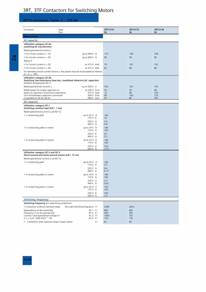
8/12/2019 SIRIUS Datasheet P-1
http://slidepdf.com/reader/full/sirius-datasheet-p-1 100/100
2 a
3RT10 contactors, 3-pole, 3 ... 250 kW
3RT, 3TF Contactors for Switching Motors
Contactor Type 3RT10 54 3RT10 55 3RT10 56 Size S6 S6 S6
Main circuit
AC capacity
Utilization category AC-6aswitching AC transformers
Rated operational current Ie
• For inrush current n = 20 up to 690 V A 115 148 148
• For inrush current n = 30 up to 690 V A 90 99 99
Rating P
• For inrush current n = 20 at 415 V kVA 79 102 102
• For inrush current n = 30 at 415 V kVA 62 68 68
For deviating inrush current factors x, the power must be recalculated as follows:P x = P n 30 · 30/x
Utilization category AC-6bSwitching low-inductance (low-loss, metallized dielectric) AC capacitorsAmbient temperature 40 °C
Rated operational currents Ie up to 500 V A 105 125 145
Rated power for single capacitors or at 230 V kvar 42 50 58banks of capacitors (minimum inductance 415 V kvar 72 86 100of 6 mH between capacitors connected 500 V kvar 90 108 125in parallel) at 50 Hz, 60 Hz 690 V kvar 72 86 100
DC capacity Utilization category DC-1Switching resistive load (L/R ≤ 1 ms)
Rated operational current Ie (at 60 °C)
• 1 conducting path up to 24 V A 160110 V A 18
220 V A 3.4440 V A 0.8
• 2 conducting paths in series up to 24 V A 160110 V A 160
220 V A 20440 V A 3.2
• 3 conducting paths in series up to 24 V A 160110 V A 160
220 V A 160440 V A 11.5
Utilization category DC-3 and DC-5Shunt-wound and series-wound motors (L/R ≤ 15 ms)
Rated operational current Ie (at 60 °C)
• 1 conducting path up to 24 V A 160110 V A 2.5
220 V A 0.6440 V A 0.17
• 2 conducting paths in series up to 24 V A 160110 V A 160
220 V A 2.5440 V A 0 65