Single Packaged Convertible - Trane
40
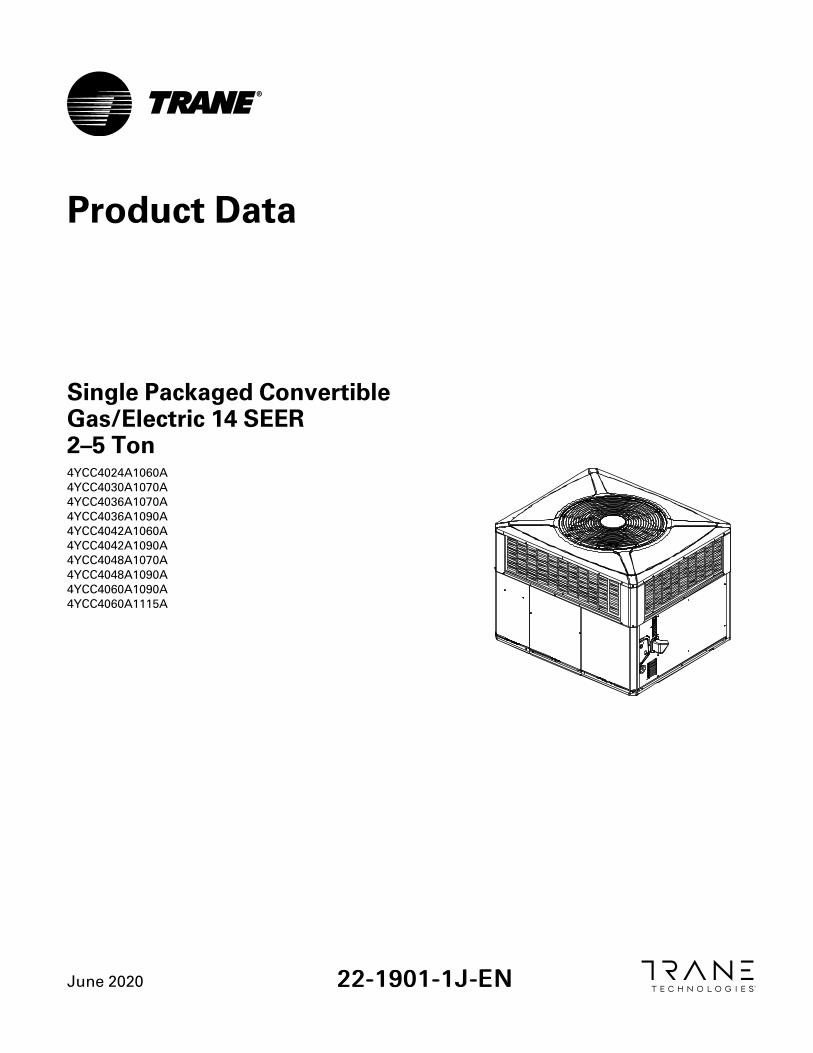
June2020 22-1901-1J-EN Single Packaged Convertible Gas/Electric 14 SEER 2–5 Ton 4YCC4024A1060A 4YCC4030A1070A 4YCC4036A1070A 4YCC4036A1090A 4YCC4042A1060A 4YCC4042A1090A 4YCC4048A1070A 4YCC4048A1090A 4YCC4060A1090A 4YCC4060A1115A Product Data
Transcript of Single Packaged Convertible - Trane
June 2020 2222--11990011--11JJ--EENN
Single Packaged ConvertibleGas/Electric 14 SEER2–5 Ton4YCC4024A1060A4YCC4030A1070A4YCC4036A1070A4YCC4036A1090A4YCC4042A1060A4YCC4042A1090A4YCC4048A1070A4YCC4048A1090A4YCC4060A1090A4YCC4060A1115A
Product Data
©2020 Trane 22-1901-1J-EN
SAFETY SECTIONIImmppoorrttaanntt— This document contains a wiring diagram, a parts list, and service information.This is customer property and is to remain with this unit. Please return to service informationpack upon completion of work.
WWAARRNNIINNGGHHAAZZAARRDDOOUUSS GGAASSEESS!!EExxppoossuurree ttoo ffuueell ssuubbssttaanncceess oorr bbyy--pprroodduuccttss ooff iinnccoommpplleettee ffuueell ccoommbbuussttiioonn iiss bbeelliieevveedd bbyytthhee ssttaattee ooff CCaalliiffoorrnniiaa ttoo ccaauussee ccaanncceerr,, bbiirrtthh ddeeffeeccttss,, oorr ootthheerr rreepprroodduuccttiivvee hhaarrmm..TThhiiss wwaarrnniinngg ccoommpplliieess wwiitthh ssttaattee ooff CCaalliiffoorrnniiaa llaaww,, PPrrooppoossiittiioonn 6655..
WWAARRNNIINNGGHHAAZZAARRDDOOUUSS VVOOLLTTAAGGEE!!FFaaiilluurree ttoo ffoollllooww tthhiiss WWaarrnniinngg ccoouulldd rreessuulltt iinn pprrooppeerrttyy ddaammaaggee,, sseevveerree ppeerrssoonnaall iinnjjuurryy,, oorrddeeaatthh..DDiissccoonnnneecctt aallll eelleeccttrriicc ppoowweerr,, iinncclluuddiinngg rreemmoottee ddiissccoonnnneeccttss bbeeffoorree sseerrvviicciinngg.. FFoolllloowwpprrooppeerr lloocckkoouutt//ttaaggoouutt pprroocceedduurreess ttoo eennssuurree tthhee ppoowweerr ccaannnnoott bbee iinnaaddvveerrtteennttllyy eenneerrggiizzeedd..
WWAARRNNIINNGGSSAAFFEETTYY AANNDD EELLEECCTTRRIICCAALL HHAAZZAARRDD!!FFaaiilluurree ttoo ffoollllooww tthhiiss WWaarrnniinngg ccoouulldd rreessuulltt iinn pprrooppeerrttyy ddaammaaggee,, sseevveerree ppeerrssoonnaall iinnjjuurryy,, oorrddeeaatthh..TThheessee sseerrvviicciinngg iinnssttrruuccttiioonnss aarree ffoorr uussee bbyy qquuaalliiffiieedd ppeerrssoonnnneell oonnllyy.. TToo rreedduuccee tthhee rriisskk ooffeelleeccttrriiccaall sshhoocckk,, ddoo nnoott ppeerrffoorrmm aannyy sseerrvviicciinngg ootthheerr tthhaann tthhaatt ccoonnttaaiinneedd iinn tthheesseeooppeerraattiinngg iinnssttrruuccttiioonnss uunnlleessss yyoouu aarree qquuaalliiffiieedd ttoo ddoo ssoo..
CCAAUUTTIIOONNGGRROOUUNNDDIINNGG RREEQQUUIIRREEDD!!FFaaiilluurree ttoo iinnssppeecctt oorr uussee pprrooppeerr sseerrvviiccee ttoooollss mmaayy rreessuulltt iinn eeqquuiippmmeenntt ddaammaaggee oorrppeerrssoonnaall iinnjjuurryy..RReeccoonnnneecctt aallll ggrroouunnddiinngg ddeevviicceess.. AAllll ppaarrttss ooff tthhiiss pprroodduucctt tthhaatt aarree ccaappaabbllee ooff ccoonndduuccttiinnggeelleeccttrriiccaall ccuurrrreenntt aarree ggrroouunnddeedd.. IIff ggrroouunnddiinngg wwiirreess,, ssccrreewwss,, ssttrraappss,, cclliippss,, nnuuttss,, oorr wwaasshheerrssuusseedd ttoo ccoommpplleettee aa ppaatthh ttoo ggrroouunndd aarree rreemmoovveedd ffoorr sseerrvviiccee,, tthheeyy mmuusstt bbee rreettuurrnneedd ttoo tthheeiirroorriiggiinnaall ppoossiittiioonn aanndd pprrooppeerrllyy ffaasstteenneedd..
WWAARRNNIINNGGUUNNIITT CCOONNTTAAIINNSS RR--441100AA RREEFFRRIIGGEERRAANNTT!!FFaaiilluurree ttoo uussee pprrooppeerr sseerrvviiccee ttoooollss mmaayy rreessuulltt iinn eeqquuiippmmeenntt ddaammaaggee oorr ppeerrssoonnaall iinnjjuurryy..RR--441100AA ooppeerraattiinngg pprreessssuurree eexxcceeeeddss tthhee lliimmiitt ooff RR--2222.. PPrrooppeerr sseerrvviiccee eeqquuiippmmeenntt iissrreeqquuiirreedd.. SSeerrvviiccee uussiinngg oonnllyy RR--441100AA RReeffrriiggeerraanntt aanndd aapppprroovveedd PPOOEE ccoommpprreessssoorr ooiill..
WWAARRNNIINNGGSSAAFFEETTYY HHAAZZAARRDD!!OOppeerraattiinngg tthhee uunniitt wwiitthhoouutt tthhee aacccceessss ppaanneellss pprrooppeerrllyy iinnssttaalllleedd mmaayy rreessuulltt iinn sseevveerreeppeerrssoonnaall iinnjjuurryy oorr ddeeaatthh..DDoo nnoott ooppeerraattee tthhee uunniitt wwiitthhoouutt tthhee eevvaappoorraattoorr ffaann aacccceessss ppaanneell oorr eevvaappoorraattoorr ccooiill aacccceessssppaanneell iinn ppllaaccee..
22-1901-1J-EN 3
WWAARRNNIINNGGWWAARRNNIINNGG!!TThhiiss pprroodduucctt ccaann eexxppoossee yyoouu ttoo cchheemmiiccaallss iinncclluuddiinngg lleeaadd,, wwhhiicchh aarree kknnoowwnn ttoo tthhee SSttaattee ooffCCaalliiffoorrnniiaa ttoo ccaauussee ccaanncceerr aanndd bbiirrtthh ddeeffeeccttss oorr ootthheerr rreepprroodduuccttiivvee hhaarrmm.. FFoorr mmoorreeiinnffoorrmmaattiioonn ggoo ttoo wwwwww..PP6655WWaarrnniinnggss..ccaa..ggoovv..
IImmppoorrttaanntt:: Wear appropriate gloves, arm sleeve protectors and eye protection when servicing ormaintaining this equipment.
IImmppoorrttaanntt:: Air filters and media wheels or plates shall meet the test requirements in UL 900.
SSAAFFEETTYY SSEECCTTIIOONN
4 22-1901-1J-EN
Single Packaged Convertible Gas/Electric Systems . . . . . . . . . . . . . . . . . . . . . . . . . . . . 5
Optional Equipment Listing. . . . . . . . . . . . . . . . . . . . . . . . . . . . . . . . . . . . . . . . . . . . . . . . . . . . 6
Product Specifications . . . . . . . . . . . . . . . . . . . . . . . . . . . . . . . . . . . . . . . . . . . . . . . . . . . . . . . . . 8
Indoor Fan Performance . . . . . . . . . . . . . . . . . . . . . . . . . . . . . . . . . . . . . . . . . . . . . . . . . . . . . . 13
Field Wiring Diagram . . . . . . . . . . . . . . . . . . . . . . . . . . . . . . . . . . . . . . . . . . . . . . . . . . . . . . . . . 20
Wiring — 4YCC4 . . . . . . . . . . . . . . . . . . . . . . . . . . . . . . . . . . . . . . . . . . . . . . . . . . . . . . . . . . . . . . 21
Full Perimeter Roof Mounting Curb . . . . . . . . . . . . . . . . . . . . . . . . . . . . . . . . . . . . . . . . . . . 27
Optional Equipment — Economizer. . . . . . . . . . . . . . . . . . . . . . . . . . . . . . . . . . . . . . . . . . . 29
Optional Equipment — Outside Air Damper . . . . . . . . . . . . . . . . . . . . . . . . . . . . . . . . . . 30
Optional Equipment — Filter Rack . . . . . . . . . . . . . . . . . . . . . . . . . . . . . . . . . . . . . . . . . . . . 31
Outline Drawings . . . . . . . . . . . . . . . . . . . . . . . . . . . . . . . . . . . . . . . . . . . . . . . . . . . . . . . . . . . . . 32
Table of Contents
22-1901-1J-EN 5
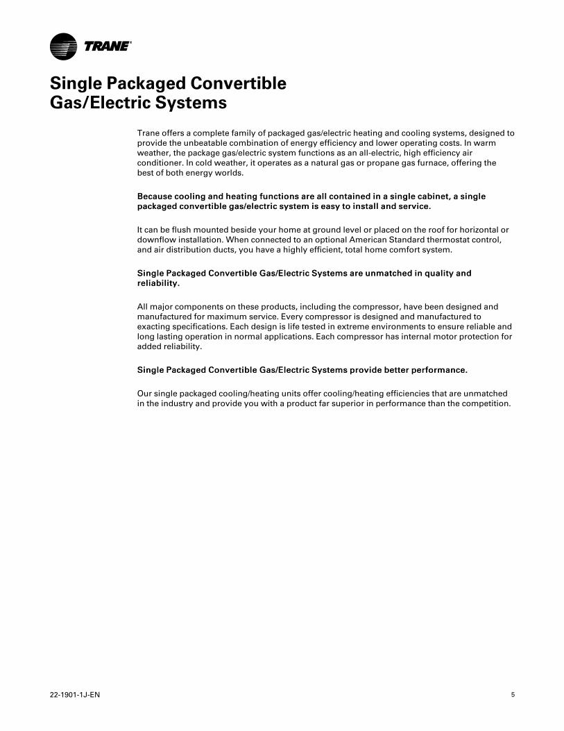
Single Packaged ConvertibleGas/Electric Systems
Trane offers a complete family of packaged gas/electric heating and cooling systems, designed toprovide the unbeatable combination of energy efficiency and lower operating costs. In warmweather, the package gas/electric system functions as an all-electric, high efficiency airconditioner. In cold weather, it operates as a natural gas or propane gas furnace, offering thebest of both energy worlds.
BBeeccaauussee ccoooolliinngg aanndd hheeaattiinngg ffuunnccttiioonnss aarree aallll ccoonnttaaiinneedd iinn aa ssiinnggllee ccaabbiinneett,, aa ssiinngglleeppaacckkaaggeedd ccoonnvveerrttiibbllee ggaass//eelleeccttrriicc ssyysstteemm iiss eeaassyy ttoo iinnssttaallll aanndd sseerrvviiccee..
It can be flush mounted beside your home at ground level or placed on the roof for horizontal ordownflow installation. When connected to an optional American Standard thermostat control,and air distribution ducts, you have a highly efficient, total home comfort system.
SSiinnggllee PPaacckkaaggeedd CCoonnvveerrttiibbllee GGaass//EElleeccttrriicc SSyysstteemmss aarree uunnmmaattcchheedd iinn qquuaalliittyy aannddrreelliiaabbiilliittyy..
All major components on these products, including the compressor, have been designed andmanufactured for maximum service. Every compressor is designed and manufactured toexacting specifications. Each design is life tested in extreme environments to ensure reliable andlong lasting operation in normal applications. Each compressor has internal motor protection foradded reliability.
SSiinnggllee PPaacckkaaggeedd CCoonnvveerrttiibbllee GGaass//EElleeccttrriicc SSyysstteemmss pprroovviiddee bbeetttteerr ppeerrffoorrmmaannccee..
Our single packaged cooling/heating units offer cooling/heating efficiencies that are unmatchedin the industry and provide you with a product far superior in performance than the competition.
6 22-1901-1J-EN
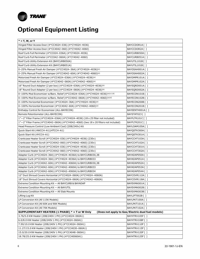
Optional Equipment Listing
* = T,W, or Y
Hinged Filter Access Door (4*CC4024–036) (4*CY4024–4036) BAYCCDOR1A [ ]
Hinged Filter Access Door (4*CC4042–060) (4*CY4042–4060) BAYCCDOR2A [ ]
Roof Curb Full Perimeter (4*CC024–036A) (4*CY4024–4036) BAYCURB050A [ ]
Roof Curb Full Perimeter (4*CC042–060A) (4*CY4042–4060) BAYCURB051A [ ]
Roof Curb Utility Extension Kit (BAYCURB050A) BAYUTIL101B [ ]
Roof Curb Utility Extension Kit (BAYCURB051A) BAYUTIL101B [ ]
0–25%Manual Fresh Air Damper (4*CC4024–36A) (4*CY4024–4036)(a) BAYOSAH001A [ ]
0–25%Manual Fresh Air Damper (4*CC4042–60A) (4*CY4042–4060)(a) BAYOSAH002A [ ]
Motorized Fresh Air Damper (4*CC4024–036A) (4*CY4024–4036)(a) BAYDMPR101A [ ]
Motorized Fresh Air Damper (4*CC4042–060A) (4*CY4042–4060)(a) BAYDMPR102A [ ]
16” Round Duct Adapter (2 per box) (4*CC4024–036A) (4*CY4024–4036)(b) BAYSQRD001A [ ]
18” Round Duct Adapter (2 per box) (4*CC4024–060A) (4*CY4024–4036)(b) BAYSQRD002A [ ]
0–100%Mod Economizer w/Baro. Relief (4*CC4024–036A) (4*CY4024–4036)(a)(c) (d) BAYECON101B [ ]
0–100%Mod Economizer w/Baro. Relief (4*CC4042–060A) (4*CY4042–4060)(a)(d) BAYECON102B [ ]
0–100% Horizontal Economizer (4*CC4024–36A) (4*CY4024–4036)(a) BAYECON200B [ ]
0–100% Horizontal Economizer (4*CC4042–60A) (4*CY4042–4060)(a) BAYECON201B [ ]
Enthalpy Control for Economizer (ALL-BAYECON) BAYEENTH001A [ ]
Remote Potentiometer (ALL-BAYECON) BAYSTAT023 [ ]
1”—2” Filter Frame (4*CC4024–036A) (4*CY4024–4036) (18 x 25 filter not included) BAYFLTR101C [ ]
1”—2” Filter Frame (4*CC4042–060A) (4*CY4042–4060) (two 18 x 20 filters not included) BAYFLTR201C [ ]
Head Pressure Control (Low Ambient Cool) (208/240v) Kit BAYLOAM105A [ ]
Quick Start Kit (4WCC4–A1)(4TCC4–A1) BAYQSTK300A [ ]
Quick Start Kit (4YCC4–A1) BAYQSTK301A [ ]
Crankcase Heater Scroll (4*CC4024–036) (4*CY4024–4036) (230v) BAYCCHT103A [ ]
Crankcase Heater Scroll (4*CC4042–060) (4*CY4042–4060) (230v) BAYCCHT102A [ ]
Crankcase Heater Scroll (4*CC4024–036) (4*CY4024–4036) (230v) BAYCCHT301A [ ]
Crankcase Heater Scroll (4*CC4042–060) (4*CY4042–4060) (230v) BAYCCHT302A [ ]
Adapter Curb (4*CC4024–36A) (4*CY4024–4036A) to BAYCURB030,38 BAYADAP050A [ ]
Adapter Curb (4*CC4024–36A) (4*CY4024–4036A) to BAYCURB033 BAYADAP051A [ ]
Adapter Curb (4*CC4042–60A) (4*CY4042–4060A) to BAYCURB030,38 BAYADAP052A [ ]
Adapter Curb (4*CC4042–60A) (4*CY4042–4060A) to BAYCURB033 BAYADAP053A [ ]
Adapter Curb (4*CC4042–60A) (4*CY4042–4060A) to BAYCURB034 BAYADAP054A [ ]
12” Duct Shroud Covers Horizontal (4*CC4024–060A) (4*CY4024–4060A) BAYCOVR112A [ ]
18” Duct Shroud Covers Horizontal (4*CC4024–060A) (4*CY4042–4060A) BAYCOVR118A [ ]
Extreme Condition Mounting Kit — All BAYCURB & BAYADAP BAYEXMK001A [ ]
Extreme Condition Mounting Kit — All BAYUTIL BAYEXMK002B [ ]
Extreme Condition Mounting Kit — All Slab Mounts BAYEXMK003B [ ]
Lifting Lug Kit BAYLIFT002B [ ]
LP Conversion Kit (All 115K Models) BAYLPKT100A [ ]
LP Conversion Kit (All 60K and 90K Models) BAYLPKT101A [ ]
LP Conversion Kit (All 70K Models) BAYLPKT102A [ ]
SUPPLEMENTARY HEATERS (1 PHASE) * = T orWOnly (Does not apply to Gas/Electric dual fuel models)3.76/5.0 KW Heater (208/240V 1 PH) (4*CC4024–060A1) BAYHTRV105F [ ]
6.0/8.0 KW Heater (208/240V 1 PH) (4*CC4024–060A1) BAYHTRV108F [ ]
7.50/10.0 KW Heater (208/240V 1 PH) (4*CC4024–060A1) BAYHTRV110F [ ]
11.27/15.0 KW Heater (208/240V 1 PH) (4*CC4030–060A1) BAYHTRV115F [ ]
15.0/20.0 KW Heater (208/240V 1 PH) (4*CC4048–060A1) BAYHTRV120F [ ]
18.78/25.0 KW Heater (208/240V 1 PH) (4*CC40060A1) BAYHTRV125F [ ]
22-1901-1J-EN 7
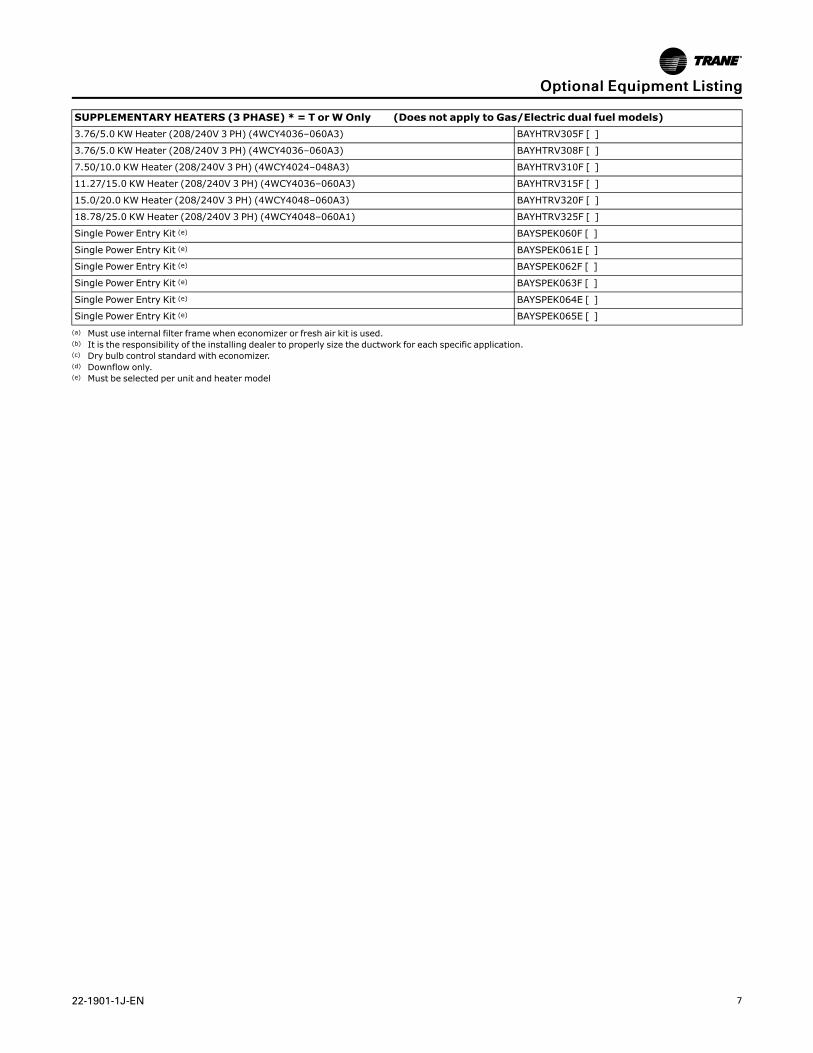
SUPPLEMENTARY HEATERS (3 PHASE) * = T orWOnly (Does not apply to Gas/Electric dual fuel models)3.76/5.0 KW Heater (208/240V 3 PH) (4WCY4036–060A3) BAYHTRV305F [ ]
3.76/5.0 KW Heater (208/240V 3 PH) (4WCY4036–060A3) BAYHTRV308F [ ]
7.50/10.0 KW Heater (208/240V 3 PH) (4WCY4024–048A3) BAYHTRV310F [ ]
11.27/15.0 KW Heater (208/240V 3 PH) (4WCY4036–060A3) BAYHTRV315F [ ]
15.0/20.0 KW Heater (208/240V 3 PH) (4WCY4048–060A3) BAYHTRV320F [ ]
18.78/25.0 KW Heater (208/240V 3 PH) (4WCY4048–060A1) BAYHTRV325F [ ]
Single Power Entry Kit (e) BAYSPEK060F [ ]
Single Power Entry Kit (e) BAYSPEK061E [ ]
Single Power Entry Kit (e) BAYSPEK062F [ ]
Single Power Entry Kit (e) BAYSPEK063F [ ]
Single Power Entry Kit (e) BAYSPEK064E [ ]
Single Power Entry Kit (e) BAYSPEK065E [ ](a) Must use internal filter frame when economizer or fresh air kit is used.(b) It is the responsibility of the installing dealer to properly size the ductwork for each specific application.(c) Dry bulb control standard with economizer.(d) Downflow only.(e) Must be selected per unit and heater model
OOppttiioonnaall EEqquuiippmmeenntt LLiissttiinngg
8 22-1901-1J-EN
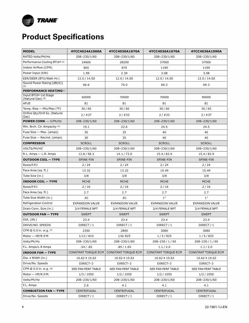
Product Specifications
MODEL 4YCC4024A1060A 4YCC4030A1070A 4YCC4036A1070A 4YCC4036A1090ARATED Volts/PH/Hz 208–230/1/60 208–230/1/60 208–230/1/60 208–230/1/60
Performance Cooling BTUH (a) 24600 28200 37000 37000
Indoor Airflow (CFM) 805 870 1190 1190
Power Input (KW) 1.99 2.39 3.08 3.08
EER/SEER (BTU/Watt-Hr.) 12.0 / 14.00 12.0 / 14.00 12.0 / 14.00 12.0 / 14.00Sound Power Rating [dB(A)](b) 66.6 70.0 69.3 69.3
PERFORMANCE HEATING(c)
Input BTUH-1st Stage(Natural Gas) (d) 60000 70000 70000 90000
AFUE 81 81 81 81
Temp. Rise — Min/Max (°F) 30 / 60 30 / 60 30 / 60 35 / 65Orifice Qty/Drill Sz. (NaturalGas) 2 / #37 2 / #33 2 / #33 3 / #37
POWER CONN.— V/Ph/Hz 208–230/1/60 208–230/1/60 208–230/1/60 208–230/1/60
Min. Brch. Cir. Ampacity (e) 19.1 22.6 24.5 24.5
Fuse Size — Max. (amps) 30 35 40 40
Fuse Size — Recmd. (amps) 30 35 40 40
COMPRESSOR SCROLL SCROLL SCROLL SCROLL
VOLTS/PH/HZ 208–230/1/60 208–230/1/60 208–230/1/60 208–230/1/60
R.L. Amps — L.R. Amps 12.8 / 58.3 14.1 / 73.0 15.4 / 83.9 15.4 / 83.9
OUTDOOR COIL — TYPE SPINE-FIN SPINE-FIN SPINE-FIN SPINE-FIN
Rows/F.P.I 2 / 24 2 / 24 2 / 24 2 / 24
Face Area (sq. ft.) 13.32 13.32 15.49 15.49
Tube Size (in.) 3/8 3/8 3/8 3/8
INDOOR COIL — TYPE MCHE MCHE MCHE MCHE
Rows/F.P.I 2 / 16 2 / 16 2 / 16 2 / 16
Face Area (sq. ft.) 2.7 2.7 2.7 2.7
Tube Size Width (in.) .81 .81 1” 1”
Refrigeration Control EXPANSION VALVE EXPANSION VALVE EXPANSION VALVE EXPANSION VALVE
Drain Conn. Size (in.) 3/4 FEMALE NPT 3/4 FEMALE NPT 3/4 FEMALE NPT 3/4 FEMALE NPT
OUTDOOR FAN— TYPE SWEPT SWEPT SWEPT SWEPT
DIA. (IN.) 23.4 23.4 23.4 23.4
DRIVE/NO. SPEEDS DIRECT / 1 DIRECT / 1 DIRECT / 1 DIRECT / 1
CFM@ 0.0 in. w.g. (f) 2350 2800 3080 3080
Motor — HP/R.P.M 1/12 / 810 1/6/ 825 1 / 5 / 825 1 / 5 / 825
Volts/Ph/Hz 208–230/1/60 208–230/1/60 208–230 / 1 / 60 208–230 / 1 / 60
F.L. Amps/L.R Amps .54 / .82 .85 / 1.65 1.1 / 2.0 1.1 / 2.0
INDOOR FAN— TYPE CONSTANT TORQUE ECM CONSTANT TORQUE ECM CONSTANT TORQUE ECM CONSTANT TORQUE ECM
Dia. x Width (in.) 10.62 X 10.62 10.62 X 10.62 10.62 X 10.62 10.62 X 10.62
Drive/No. Speeds DIRECT–3 DIRECT–3 DIRECT–3 DIRECT–3
CFM@ 0.0 in. w.g. (g) SEE FAN PERF TABLE SEE FAN PERF TABLE SEE FAN PERF TABLE SEE FAN PERF TABLE
Motor — HP/R.P.M. 1/3 / 1050 1/2 / 1050 1/2 / 1050 1/2 / 1050
Volts/Ph/Hz 208–230/1/60 208–230/1/60 208–230/1/60 208–230/1/60
F.L. Amps 2.6 4.1 4.1 4.1
COMBUSTION FAN— TYPE CENTRIFUGAL CENTRIFUGAL CENTRIFUGAL CENTRIFUGAL
Drive/No. Speeds DIRECT / 1 DIRECT / 1 DIRECT / 1 DIRECT / 1
22-1901-1J-EN 9
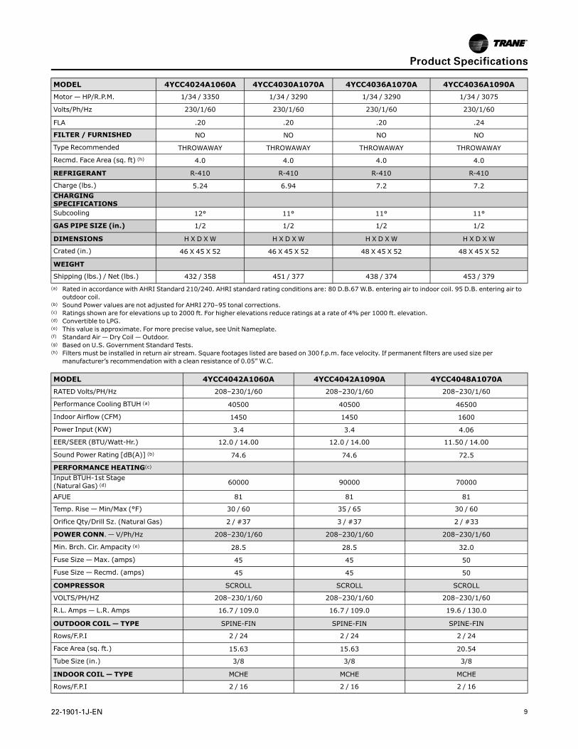
MODEL 4YCC4024A1060A 4YCC4030A1070A 4YCC4036A1070A 4YCC4036A1090AMotor — HP/R.P.M. 1/34 / 3350 1/34 / 3290 1/34 / 3290 1/34 / 3075
Volts/Ph/Hz 230/1/60 230/1/60 230/1/60 230/1/60
FLA .20 .20 .20 .24
FILTER / FURNISHED NO NO NO NO
Type Recommended THROWAWAY THROWAWAY THROWAWAY THROWAWAY
Recmd. Face Area (sq. ft) (h) 4.0 4.0 4.0 4.0
REFRIGERANT R-410 R-410 R-410 R-410
Charge (lbs.) 5.24 6.94 7.2 7.2CHARGINGSPECIFICATIONSSubcooling 12° 11° 11° 11°
GAS PIPE SIZE (in.) 1/2 1/2 1/2 1/2
DIMENSIONS H X D XW H X D XW H X D XW H X D XW
Crated (in.) 46 X 45 X 52 46 X 45 X 52 48 X 45 X 52 48 X 45 X 52
WEIGHT
Shipping (lbs.) / Net (lbs.) 432 / 358 451 / 377 438 / 374 453 / 379(a) Rated in accordance with AHRI Standard 210/240. AHRI standard rating conditions are: 80 D.B.67 W.B. entering air to indoor coil. 95 D.B. entering air to
outdoor coil.(b) Sound Power values are not adjusted for AHRI 270–95 tonal corrections.(c) Ratings shown are for elevations up to 2000 ft. For higher elevations reduce ratings at a rate of 4% per 1000 ft. elevation.(d) Convertible to LPG.(e) This value is approximate. For more precise value, see Unit Nameplate.(f) Standard Air — Dry Coil — Outdoor.(g) Based on U.S. Government Standard Tests.(h) Filters must be installed in return air stream. Square footages listed are based on 300 f.p.m. face velocity. If permanent filters are used size per
manufacturer’s recommendation with a clean resistance of 0.05” W.C.
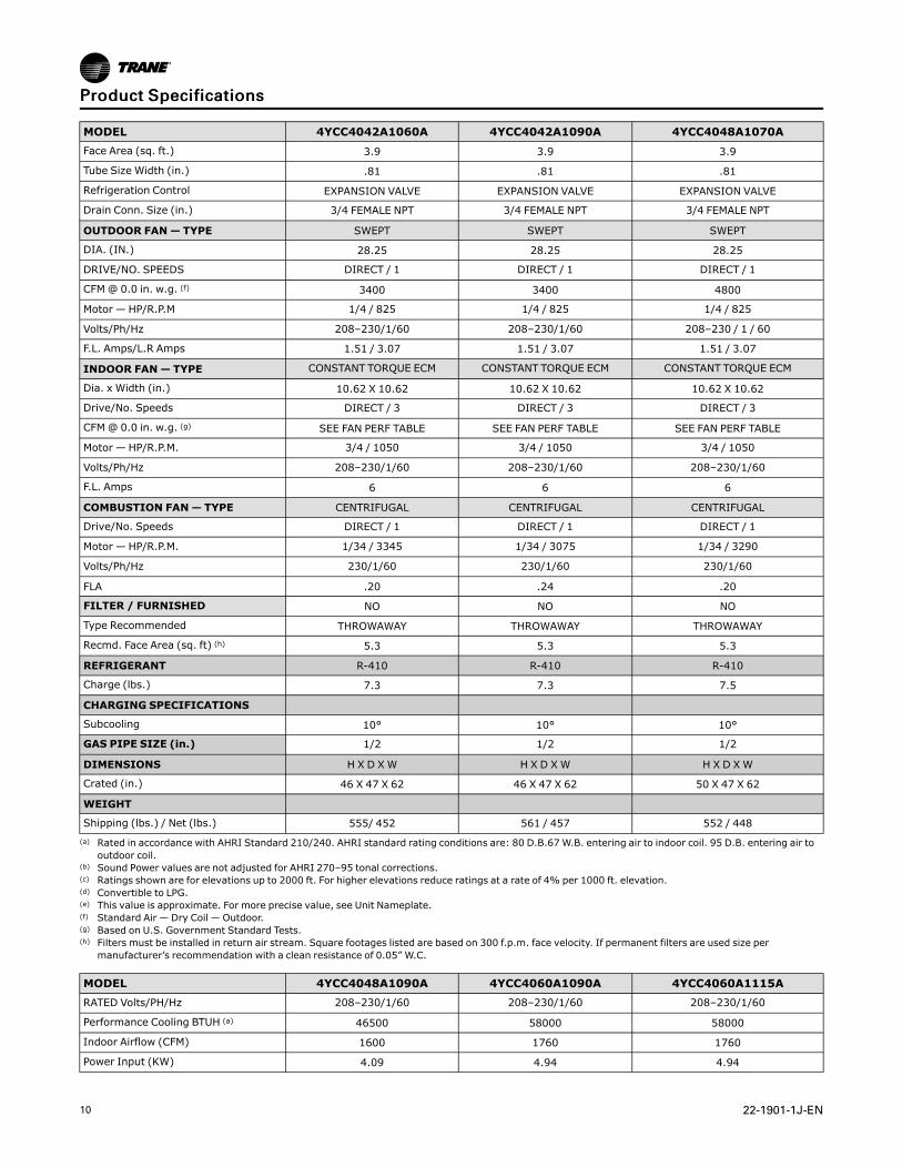
MODEL 4YCC4042A1060A 4YCC4042A1090A 4YCC4048A1070ARATED Volts/PH/Hz 208–230/1/60 208–230/1/60 208–230/1/60
Performance Cooling BTUH (a) 40500 40500 46500
Indoor Airflow (CFM) 1450 1450 1600
Power Input (KW) 3.4 3.4 4.06
EER/SEER (BTU/Watt-Hr.) 12.0 / 14.00 12.0 / 14.00 11.50 / 14.00
Sound Power Rating [dB(A)] (b) 74.6 74.6 72.5
PERFORMANCE HEATING(c)
Input BTUH-1st Stage(Natural Gas) (d) 60000 90000 70000
AFUE 81 81 81
Temp. Rise — Min/Max (°F) 30 / 60 35 / 65 30 / 60
Orifice Qty/Drill Sz. (Natural Gas) 2 / #37 3 / #37 2 / #33
POWER CONN.— V/Ph/Hz 208–230/1/60 208–230/1/60 208–230/1/60
Min. Brch. Cir. Ampacity (e) 28.5 28.5 32.0
Fuse Size — Max. (amps) 45 45 50
Fuse Size — Recmd. (amps) 45 45 50
COMPRESSOR SCROLL SCROLL SCROLL
VOLTS/PH/HZ 208–230/1/60 208–230/1/60 208–230/1/60
R.L. Amps — L.R. Amps 16.7 / 109.0 16.7 / 109.0 19.6 / 130.0
OUTDOOR COIL — TYPE SPINE-FIN SPINE-FIN SPINE-FIN
Rows/F.P.I 2 / 24 2 / 24 2 / 24
Face Area (sq. ft.) 15.63 15.63 20.54
Tube Size (in.) 3/8 3/8 3/8
INDOOR COIL — TYPE MCHE MCHE MCHE
Rows/F.P.I 2 / 16 2 / 16 2 / 16
PPrroodduucctt SSppeecciiffiiccaattiioonnss
10 22-1901-1J-EN
MODEL 4YCC4042A1060A 4YCC4042A1090A 4YCC4048A1070AFace Area (sq. ft.) 3.9 3.9 3.9
Tube Size Width (in.) .81 .81 .81
Refrigeration Control EXPANSION VALVE EXPANSION VALVE EXPANSION VALVE
Drain Conn. Size (in.) 3/4 FEMALE NPT 3/4 FEMALE NPT 3/4 FEMALE NPT
OUTDOOR FAN— TYPE SWEPT SWEPT SWEPT
DIA. (IN.) 28.25 28.25 28.25
DRIVE/NO. SPEEDS DIRECT / 1 DIRECT / 1 DIRECT / 1
CFM@ 0.0 in. w.g. (f) 3400 3400 4800
Motor — HP/R.P.M 1/4 / 825 1/4 / 825 1/4 / 825
Volts/Ph/Hz 208–230/1/60 208–230/1/60 208–230 / 1 / 60
F.L. Amps/L.R Amps 1.51 / 3.07 1.51 / 3.07 1.51 / 3.07
INDOOR FAN— TYPE CONSTANT TORQUE ECM CONSTANT TORQUE ECM CONSTANT TORQUE ECM
Dia. x Width (in.) 10.62 X 10.62 10.62 X 10.62 10.62 X 10.62
Drive/No. Speeds DIRECT / 3 DIRECT / 3 DIRECT / 3
CFM@ 0.0 in. w.g. (g) SEE FAN PERF TABLE SEE FAN PERF TABLE SEE FAN PERF TABLE
Motor — HP/R.P.M. 3/4 / 1050 3/4 / 1050 3/4 / 1050
Volts/Ph/Hz 208–230/1/60 208–230/1/60 208–230/1/60
F.L. Amps 6 6 6
COMBUSTION FAN— TYPE CENTRIFUGAL CENTRIFUGAL CENTRIFUGAL
Drive/No. Speeds DIRECT / 1 DIRECT / 1 DIRECT / 1
Motor — HP/R.P.M. 1/34 / 3345 1/34 / 3075 1/34 / 3290
Volts/Ph/Hz 230/1/60 230/1/60 230/1/60
FLA .20 .24 .20
FILTER / FURNISHED NO NO NO
Type Recommended THROWAWAY THROWAWAY THROWAWAY
Recmd. Face Area (sq. ft) (h) 5.3 5.3 5.3
REFRIGERANT R-410 R-410 R-410
Charge (lbs.) 7.3 7.3 7.5
CHARGING SPECIFICATIONS
Subcooling 10° 10° 10°
GAS PIPE SIZE (in.) 1/2 1/2 1/2
DIMENSIONS H X D XW H X D XW H X D XW
Crated (in.) 46 X 47 X 62 46 X 47 X 62 50 X 47 X 62
WEIGHT
Shipping (lbs.) / Net (lbs.) 555/ 452 561 / 457 552 / 448(a) Rated in accordance with AHRI Standard 210/240. AHRI standard rating conditions are: 80 D.B.67 W.B. entering air to indoor coil. 95 D.B. entering air to
outdoor coil.(b) Sound Power values are not adjusted for AHRI 270–95 tonal corrections.(c) Ratings shown are for elevations up to 2000 ft. For higher elevations reduce ratings at a rate of 4% per 1000 ft. elevation.(d) Convertible to LPG.(e) This value is approximate. For more precise value, see Unit Nameplate.(f) Standard Air — Dry Coil — Outdoor.(g) Based on U.S. Government Standard Tests.(h) Filters must be installed in return air stream. Square footages listed are based on 300 f.p.m. face velocity. If permanent filters are used size per
manufacturer’s recommendation with a clean resistance of 0.05” W.C.
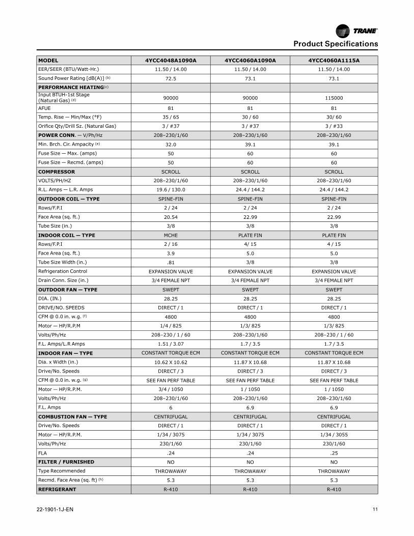
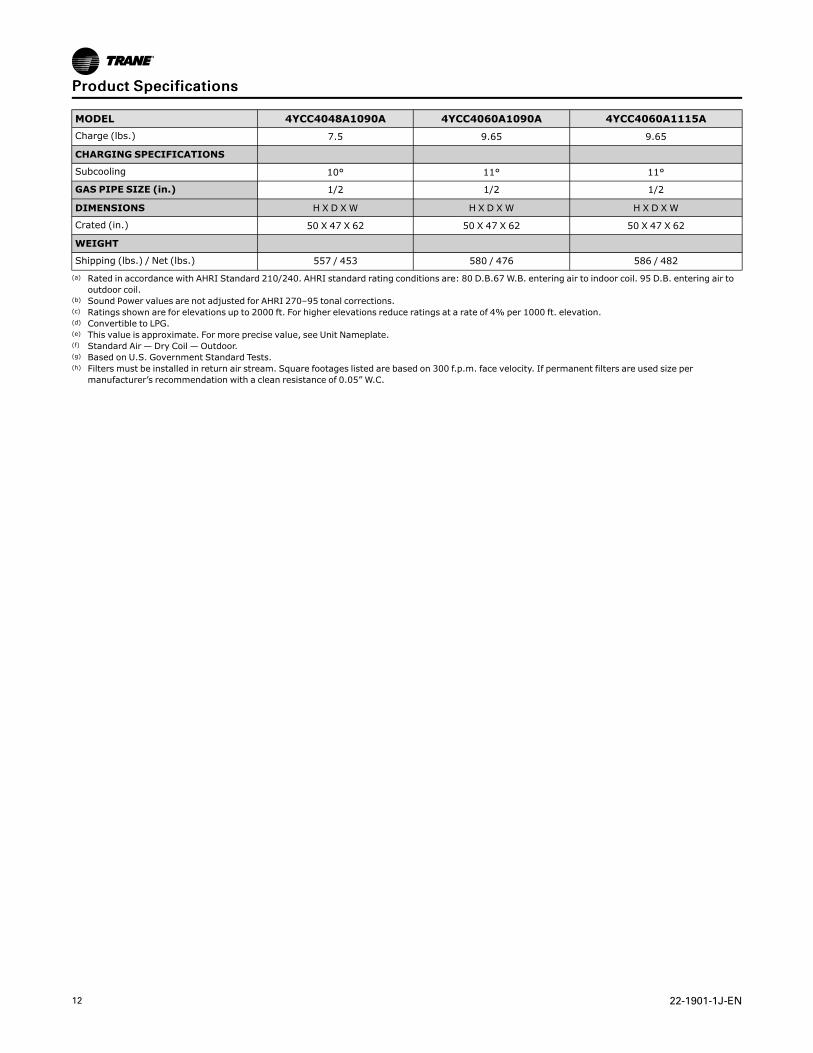
MODEL 4YCC4048A1090A 4YCC4060A1090A 4YCC4060A1115ARATED Volts/PH/Hz 208–230/1/60 208–230/1/60 208–230/1/60
Performance Cooling BTUH (a) 46500 58000 58000
Indoor Airflow (CFM) 1600 1760 1760
Power Input (KW) 4.09 4.94 4.94
PPrroodduucctt SSppeecciiffiiccaattiioonnss
22-1901-1J-EN 11
MODEL 4YCC4048A1090A 4YCC4060A1090A 4YCC4060A1115AEER/SEER (BTU/Watt-Hr.) 11.50 / 14.00 11.50 / 14.00 11.50 / 14.00
Sound Power Rating [dB(A)] (b) 72.5 73.1 73.1
PERFORMANCE HEATING(c)
Input BTUH-1st Stage(Natural Gas) (d) 90000 90000 115000
AFUE 81 81 81
Temp. Rise — Min/Max (°F) 35 / 65 30 / 60 30/ 60
Orifice Qty/Drill Sz. (Natural Gas) 3 / #37 3 / #37 3 / #33
POWER CONN.— V/Ph/Hz 208–230/1/60 208–230/1/60 208–230/1/60
Min. Brch. Cir. Ampacity (e) 32.0 39.1 39.1
Fuse Size — Max. (amps) 50 60 60
Fuse Size — Recmd. (amps) 50 60 60
COMPRESSOR SCROLL SCROLL SCROLL
VOLTS/PH/HZ 208–230/1/60 208–230/1/60 208–230/1/60
R.L. Amps — L.R. Amps 19.6 / 130.0 24.4 / 144.2 24.4 / 144.2
OUTDOOR COIL — TYPE SPINE-FIN SPINE-FIN SPINE-FIN
Rows/F.P.I 2 / 24 2 / 24 2 / 24
Face Area (sq. ft.) 20.54 22.99 22.99
Tube Size (in.) 3/8 3/8 3/8
INDOOR COIL — TYPE MCHE PLATE FIN PLATE FIN
Rows/F.P.I 2 / 16 4/ 15 4 / 15
Face Area (sq. ft.) 3.9 5.0 5.0
Tube Size Width (in.) .81 3/8 3/8
Refrigeration Control EXPANSION VALVE EXPANSION VALVE EXPANSION VALVE
Drain Conn. Size (in.) 3/4 FEMALE NPT 3/4 FEMALE NPT 3/4 FEMALE NPT
OUTDOOR FAN— TYPE SWEPT SWEPT SWEPT
DIA. (IN.) 28.25 28.25 28.25
DRIVE/NO. SPEEDS DIRECT / 1 DIRECT / 1 DIRECT / 1
CFM@ 0.0 in. w.g. (f) 4800 4800 4800
Motor — HP/R.P.M 1/4 / 825 1/3/ 825 1/3/ 825
Volts/Ph/Hz 208–230 / 1 / 60 208–230/1/60 208–230 / 1 / 60
F.L. Amps/L.R Amps 1.51 / 3.07 1.7 / 3.5 1.7 / 3.5
INDOOR FAN— TYPE CONSTANT TORQUE ECM CONSTANT TORQUE ECM CONSTANT TORQUE ECM
Dia. x Width (in.) 10.62 X 10.62 11.87 X 10.68 11.87 X 10.68
Drive/No. Speeds DIRECT / 3 DIRECT / 3 DIRECT / 3
CFM@ 0.0 in. w.g. (g) SEE FAN PERF TABLE SEE FAN PERF TABLE SEE FAN PERF TABLE
Motor — HP/R.P.M. 3/4 / 1050 1 / 1050 1 / 1050
Volts/Ph/Hz 208–230/1/60 208–230/1/60 208–230/1/60
F.L. Amps 6 6.9 6.9
COMBUSTION FAN— TYPE CENTRIFUGAL CENTRIFUGAL CENTRIFUGAL
Drive/No. Speeds DIRECT / 1 DIRECT / 1 DIRECT / 1
Motor — HP/R.P.M. 1/34 / 3075 1/34 / 3075 1/34 / 3055
Volts/Ph/Hz 230/1/60 230/1/60 230/1/60
FLA .24 .24 .25
FILTER / FURNISHED NO NO NO
Type Recommended THROWAWAY THROWAWAY THROWAWAY
Recmd. Face Area (sq. ft) (h) 5.3 5.3 5.3
REFRIGERANT R-410 R-410 R-410
PPrroodduucctt SSppeecciiffiiccaattiioonnss
12 22-1901-1J-EN
MODEL 4YCC4048A1090A 4YCC4060A1090A 4YCC4060A1115ACharge (lbs.) 7.5 9.65 9.65
CHARGING SPECIFICATIONS
Subcooling 10° 11° 11°
GAS PIPE SIZE (in.) 1/2 1/2 1/2
DIMENSIONS H X D XW H X D XW H X D XW
Crated (in.) 50 X 47 X 62 50 X 47 X 62 50 X 47 X 62
WEIGHT
Shipping (lbs.) / Net (lbs.) 557 / 453 580 / 476 586 / 482(a) Rated in accordance with AHRI Standard 210/240. AHRI standard rating conditions are: 80 D.B.67 W.B. entering air to indoor coil. 95 D.B. entering air to
outdoor coil.(b) Sound Power values are not adjusted for AHRI 270–95 tonal corrections.(c) Ratings shown are for elevations up to 2000 ft. For higher elevations reduce ratings at a rate of 4% per 1000 ft. elevation.(d) Convertible to LPG.(e) This value is approximate. For more precise value, see Unit Nameplate.(f) Standard Air — Dry Coil — Outdoor.(g) Based on U.S. Government Standard Tests.(h) Filters must be installed in return air stream. Square footages listed are based on 300 f.p.m. face velocity. If permanent filters are used size per
manufacturer’s recommendation with a clean resistance of 0.05” W.C.
PPrroodduucctt SSppeecciiffiiccaattiioonnss
22-1901-1J-EN 13
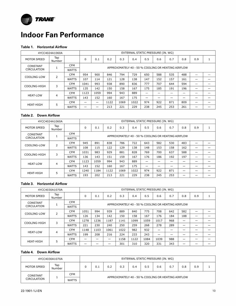
Indoor Fan PerformanceTable 1. Horizontal Airflow
4YCC4024A1060A EXTERNAL STATIC PRESSURE (IN. WG)
MOTOR SPEED TapNumber 0 0.1 0.2 0.3 0.4 0.5 0.6 0.7 0.8 0.9 1
CONSTANTCIRCULATION 1
CFMAPPROXIMATELY 40 - 50% COOLING OR HEATING AIRFLOW
WATTS
COOLING-LOW 2CFM 954 900 846 794 729 650 588 535 488 — —
WATTS 107 114 121 128 138 147 152 157 161 — —
COOLING-HIGH 3CFM 1041 993 938 890 836 777 707 644 594 — —
WATTS 135 142 150 158 167 175 185 191 196 — —
HEAT-LOW 4CFM 1123 1059 994 943 889 — — — — — —
WATTS 143 152 160 167 175 — — — — — —
HEAT-HIGH 5CFM — — 1122 1069 1022 974 922 871 809 — —
WATTS — — 213 221 229 238 245 253 261 — —
Table 2. Down Airflow
4YCC4024A1060A EXTERNAL STATIC PRESSURE (IN. WG)
MOTOR SPEED TapNumber 0 0.1 0.2 0.3 0.4 0.5 0.6 0.7 0.8 0.9 1
CONSTANTCIRCULATION 1
CFMAPPROXIMATELY 40 - 50% COOLING OR HEATING AIRFLOW
WATTS
COOLING-LOW 2CFM 945 891 838 786 722 643 582 530 483 — —
WATTS 108 115 122 129 138 148 153 158 162 — —
COOLING-HIGH 3CFM 1031 983 929 881 828 769 700 637 588 — —
WATTS 136 143 151 159 167 176 186 192 197 — —
HEAT-LOW 4CFM 1123 1059 994 943 889 — — — — — —
WATTS 143 152 160 167 175 — — — — — —
HEAT-HIGH 5CFM 1240 1184 1122 1069 1022 974 922 871 — — —
WATTS 193 202 213 221 229 238 245 253 — — —
Table 3. Horizontal Airflow
4YCC4030A1070A EXTERNAL STATIC PRESSURE (IN. WG)
MOTOR SPEED TapNumber 0 0.1 0.2 0.3 0.4 0.5 0.6 0.7 0.8 0.9 1
CONSTANTCIRCULATION 1
CFMAPPROXIMATELY 40 - 50% COOLING OR HEATING AIRFLOW
WATTS
COOLING-LOW 2CFM 1051 994 939 889 840 775 708 642 582 — —
WATTS 126 134 142 150 158 167 176 184 188 — —
COOLING-HIGH 3CFM 1278 1236 1187 1141 1099 1059 1017 968 — — —
WATTS 221 230 240 250 259 268 278 289 — — —
HEAT-LOW 4CFM 1148 1103 1061 1022 982 932 — — — — —
WATTS 199 208 216 224 233 243 — — — — —
HEAT-HIGH 5CFM — — — 1158 1122 1084 1039 988 — — —
WATTS — — — 301 310 320 331 343 — — —
Table 4. Down Airflow
4YCC4030A1070A EXTERNAL STATIC PRESSURE (IN. WG)
MOTOR SPEED TapNumber 0 0.1 0.2 0.3 0.4 0.5 0.6 0.7 0.8 0.9 1
CONSTANTCIRCULATION 1
CFMAPPROXIMATELY 40 - 50% COOLING OR HEATING AIRFLOW
WATTS
14 22-1901-1J-EN
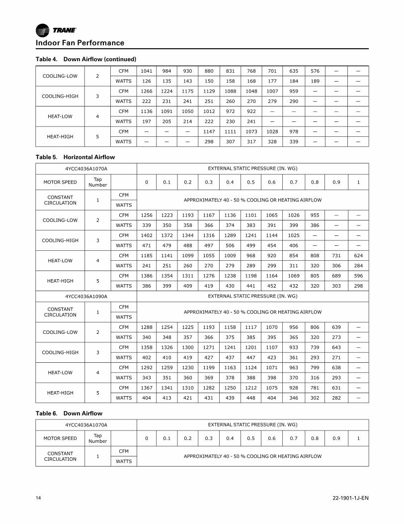
Table 4. Down Airflow (continued)
COOLING-LOW 2CFM 1041 984 930 880 831 768 701 635 576 — —
WATTS 126 135 143 150 158 168 177 184 189 — —
COOLING-HIGH 3CFM 1266 1224 1175 1129 1088 1048 1007 959 — — —
WATTS 222 231 241 251 260 270 279 290 — — —
HEAT-LOW 4CFM 1136 1091 1050 1012 972 922 — — — — —
WATTS 197 205 214 222 230 241 — — — — —
HEAT-HIGH 5CFM — — — 1147 1111 1073 1028 978 — — —
WATTS — — — 298 307 317 328 339 — — —
Table 5. Horizontal Airflow
4YCC4036A1070A EXTERNAL STATIC PRESSURE (IN. WG)
MOTOR SPEED TapNumber 0 0.1 0.2 0.3 0.4 0.5 0.6 0.7 0.8 0.9 1
CONSTANTCIRCULATION 1
CFMAPPROXIMATELY 40 - 50% COOLING OR HEATING AIRFLOW
WATTS
COOLING-LOW 2CFM 1256 1223 1193 1167 1136 1101 1065 1026 955 — —
WATTS 339 350 358 366 374 383 391 399 386 — —
COOLING-HIGH 3CFM 1402 1372 1344 1316 1289 1241 1144 1025 — — —
WATTS 471 479 488 497 506 499 454 406 — — —
HEAT-LOW 4CFM 1185 1141 1099 1055 1009 968 920 854 808 731 624
WATTS 241 251 260 270 279 289 299 311 320 306 284
HEAT-HIGH 5CFM 1386 1354 1311 1276 1238 1198 1164 1069 805 689 596
WATTS 386 399 409 419 430 441 452 432 320 303 298
4YCC4036A1090A EXTERNAL STATIC PRESSURE (IN. WG)
CONSTANTCIRCULATION 1
CFMAPPROXIMATELY 40 - 50% COOLING OR HEATING AIRFLOW
WATTS
COOLING-LOW 2CFM 1288 1254 1225 1193 1158 1117 1070 956 806 639 —
WATTS 340 348 357 366 375 385 395 365 320 273 —
COOLING-HIGH 3CFM 1358 1326 1300 1271 1241 1201 1107 933 739 643 —
WATTS 402 410 419 427 437 447 423 361 293 271 —
HEAT-LOW 4CFM 1292 1259 1230 1199 1163 1124 1071 963 799 638 —
WATTS 343 351 360 369 378 388 398 370 316 293 —
HEAT-HIGH 5CFM 1367 1341 1310 1282 1250 1212 1075 928 781 631 —
WATTS 404 413 421 431 439 448 404 346 302 282 —
Table 6. Down Airflow
4YCC4036A1070A EXTERNAL STATIC PRESSURE (IN. WG)
MOTOR SPEED TapNumber 0 0.1 0.2 0.3 0.4 0.5 0.6 0.7 0.8 0.9 1
CONSTANTCIRCULATION 1
CFMAPPROXIMATELY 40 - 50% COOLING OR HEATING AIRFLOW
WATTS
IInnddoooorr FFaann PPeerrffoorrmmaannccee
22-1901-1J-EN 15
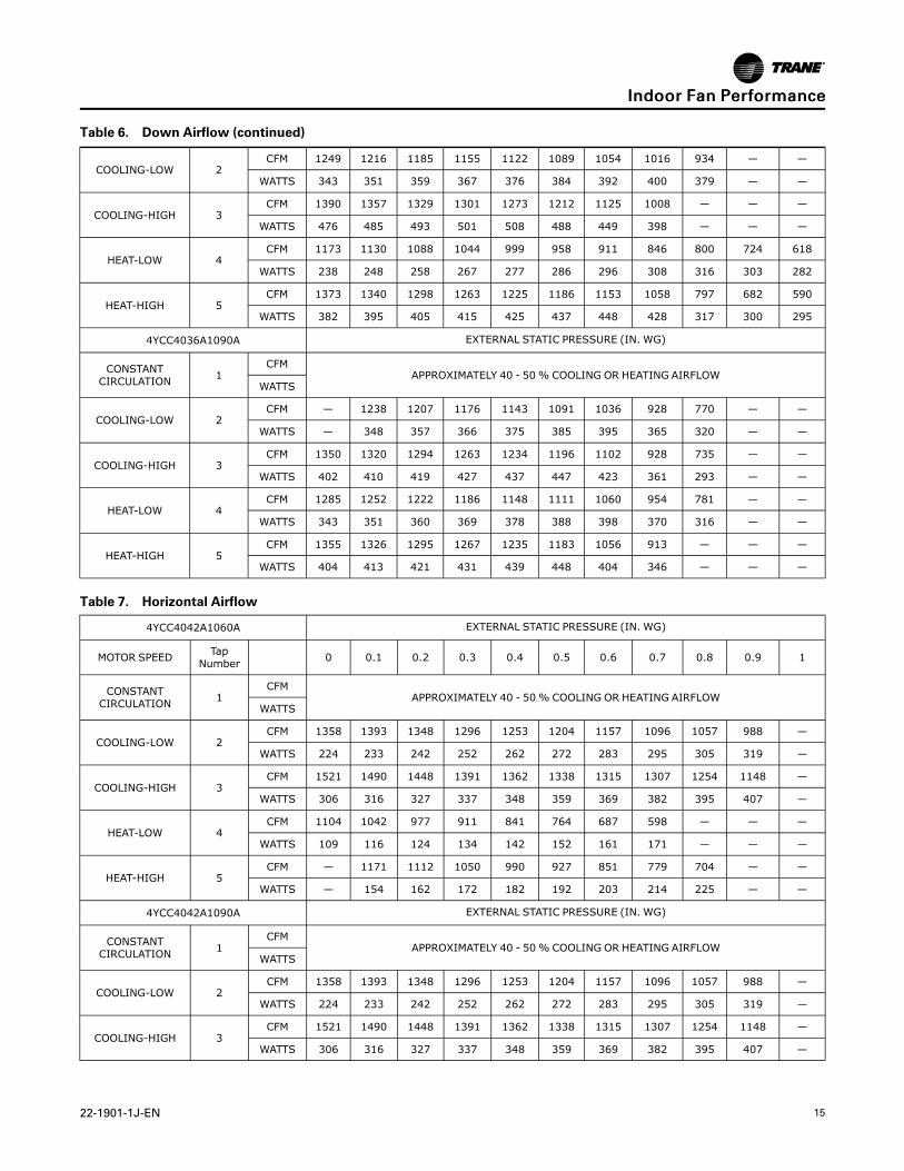
Table 6. Down Airflow (continued)
COOLING-LOW 2CFM 1249 1216 1185 1155 1122 1089 1054 1016 934 — —
WATTS 343 351 359 367 376 384 392 400 379 — —
COOLING-HIGH 3CFM 1390 1357 1329 1301 1273 1212 1125 1008 — — —
WATTS 476 485 493 501 508 488 449 398 — — —
HEAT-LOW 4CFM 1173 1130 1088 1044 999 958 911 846 800 724 618
WATTS 238 248 258 267 277 286 296 308 316 303 282
HEAT-HIGH 5CFM 1373 1340 1298 1263 1225 1186 1153 1058 797 682 590
WATTS 382 395 405 415 425 437 448 428 317 300 295
4YCC4036A1090A EXTERNAL STATIC PRESSURE (IN. WG)
CONSTANTCIRCULATION 1
CFMAPPROXIMATELY 40 - 50% COOLING OR HEATING AIRFLOW
WATTS
COOLING-LOW 2CFM — 1238 1207 1176 1143 1091 1036 928 770 — —
WATTS — 348 357 366 375 385 395 365 320 — —
COOLING-HIGH 3CFM 1350 1320 1294 1263 1234 1196 1102 928 735 — —
WATTS 402 410 419 427 437 447 423 361 293 — —
HEAT-LOW 4CFM 1285 1252 1222 1186 1148 1111 1060 954 781 — —
WATTS 343 351 360 369 378 388 398 370 316 — —
HEAT-HIGH 5CFM 1355 1326 1295 1267 1235 1183 1056 913 — — —
WATTS 404 413 421 431 439 448 404 346 — — —
Table 7. Horizontal Airflow
4YCC4042A1060A EXTERNAL STATIC PRESSURE (IN. WG)
MOTOR SPEED TapNumber 0 0.1 0.2 0.3 0.4 0.5 0.6 0.7 0.8 0.9 1
CONSTANTCIRCULATION 1
CFMAPPROXIMATELY 40 - 50% COOLING OR HEATING AIRFLOW
WATTS
COOLING-LOW 2CFM 1358 1393 1348 1296 1253 1204 1157 1096 1057 988 —
WATTS 224 233 242 252 262 272 283 295 305 319 —
COOLING-HIGH 3CFM 1521 1490 1448 1391 1362 1338 1315 1307 1254 1148 —
WATTS 306 316 327 337 348 359 369 382 395 407 —
HEAT-LOW 4CFM 1104 1042 977 911 841 764 687 598 — — —
WATTS 109 116 124 134 142 152 161 171 — — —
HEAT-HIGH 5CFM — 1171 1112 1050 990 927 851 779 704 — —
WATTS — 154 162 172 182 192 203 214 225 — —
4YCC4042A1090A EXTERNAL STATIC PRESSURE (IN. WG)
CONSTANTCIRCULATION 1
CFMAPPROXIMATELY 40 - 50% COOLING OR HEATING AIRFLOW
WATTS
COOLING-LOW 2CFM 1358 1393 1348 1296 1253 1204 1157 1096 1057 988 —
WATTS 224 233 242 252 262 272 283 295 305 319 —
COOLING-HIGH 3CFM 1521 1490 1448 1391 1362 1338 1315 1307 1254 1148 —
WATTS 306 316 327 337 348 359 369 382 395 407 —
IInnddoooorr FFaann PPeerrffoorrmmaannccee
16 22-1901-1J-EN
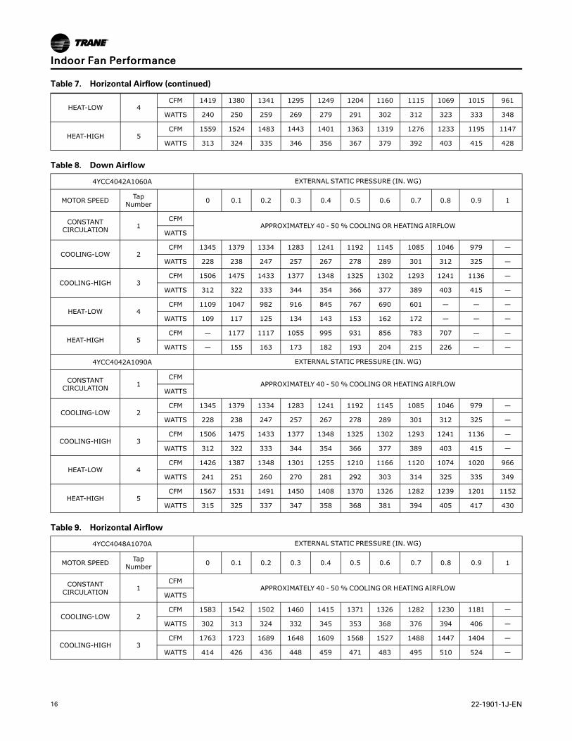
Table 7. Horizontal Airflow (continued)
HEAT-LOW 4CFM 1419 1380 1341 1295 1249 1204 1160 1115 1069 1015 961
WATTS 240 250 259 269 279 291 302 312 323 333 348
HEAT-HIGH 5CFM 1559 1524 1483 1443 1401 1363 1319 1276 1233 1195 1147
WATTS 313 324 335 346 356 367 379 392 403 415 428
Table 8. Down Airflow
4YCC4042A1060A EXTERNAL STATIC PRESSURE (IN. WG)
MOTOR SPEED TapNumber 0 0.1 0.2 0.3 0.4 0.5 0.6 0.7 0.8 0.9 1
CONSTANTCIRCULATION 1
CFMAPPROXIMATELY 40 - 50% COOLING OR HEATING AIRFLOW
WATTS
COOLING-LOW 2CFM 1345 1379 1334 1283 1241 1192 1145 1085 1046 979 —
WATTS 228 238 247 257 267 278 289 301 312 325 —
COOLING-HIGH 3CFM 1506 1475 1433 1377 1348 1325 1302 1293 1241 1136 —
WATTS 312 322 333 344 354 366 377 389 403 415 —
HEAT-LOW 4CFM 1109 1047 982 916 845 767 690 601 — — —
WATTS 109 117 125 134 143 153 162 172 — — —
HEAT-HIGH 5CFM — 1177 1117 1055 995 931 856 783 707 — —
WATTS — 155 163 173 182 193 204 215 226 — —
4YCC4042A1090A EXTERNAL STATIC PRESSURE (IN. WG)
CONSTANTCIRCULATION 1
CFMAPPROXIMATELY 40 - 50% COOLING OR HEATING AIRFLOW
WATTS
COOLING-LOW 2CFM 1345 1379 1334 1283 1241 1192 1145 1085 1046 979 —
WATTS 228 238 247 257 267 278 289 301 312 325 —
COOLING-HIGH 3CFM 1506 1475 1433 1377 1348 1325 1302 1293 1241 1136 —
WATTS 312 322 333 344 354 366 377 389 403 415 —
HEAT-LOW 4CFM 1426 1387 1348 1301 1255 1210 1166 1120 1074 1020 966
WATTS 241 251 260 270 281 292 303 314 325 335 349
HEAT-HIGH 5CFM 1567 1531 1491 1450 1408 1370 1326 1282 1239 1201 1152
WATTS 315 325 337 347 358 368 381 394 405 417 430
Table 9. Horizontal Airflow
4YCC4048A1070A EXTERNAL STATIC PRESSURE (IN. WG)
MOTOR SPEED TapNumber 0 0.1 0.2 0.3 0.4 0.5 0.6 0.7 0.8 0.9 1
CONSTANTCIRCULATION 1
CFMAPPROXIMATELY 40 - 50% COOLING OR HEATING AIRFLOW
WATTS
COOLING-LOW 2CFM 1583 1542 1502 1460 1415 1371 1326 1282 1230 1181 —
WATTS 302 313 324 332 345 353 368 376 394 406 —
COOLING-HIGH 3CFM 1763 1723 1689 1648 1609 1568 1527 1488 1447 1404 —
WATTS 414 426 436 448 459 471 483 495 510 524 —
IInnddoooorr FFaann PPeerrffoorrmmaannccee
22-1901-1J-EN 17
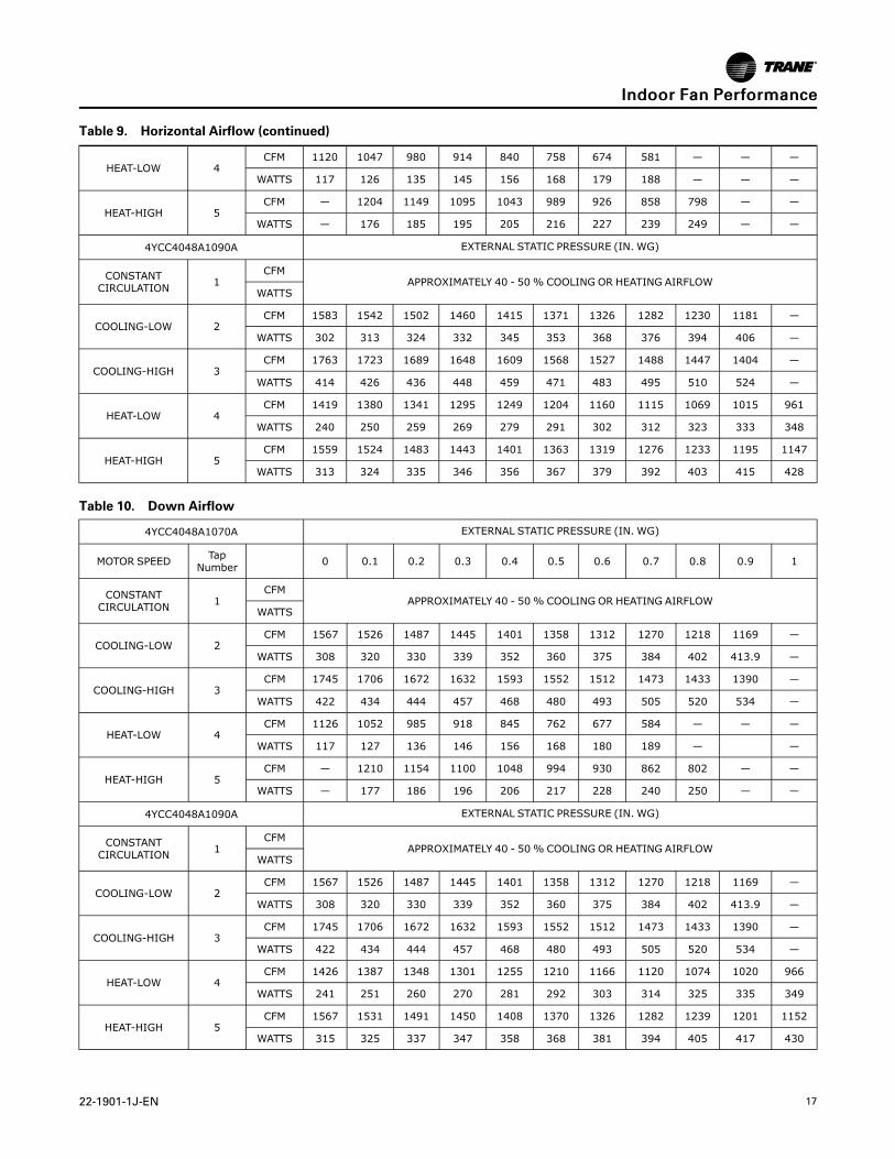
Table 9. Horizontal Airflow (continued)
HEAT-LOW 4CFM 1120 1047 980 914 840 758 674 581 — — —
WATTS 117 126 135 145 156 168 179 188 — — —
HEAT-HIGH 5CFM — 1204 1149 1095 1043 989 926 858 798 — —
WATTS — 176 185 195 205 216 227 239 249 — —
4YCC4048A1090A EXTERNAL STATIC PRESSURE (IN. WG)
CONSTANTCIRCULATION 1
CFMAPPROXIMATELY 40 - 50% COOLING OR HEATING AIRFLOW
WATTS
COOLING-LOW 2CFM 1583 1542 1502 1460 1415 1371 1326 1282 1230 1181 —
WATTS 302 313 324 332 345 353 368 376 394 406 —
COOLING-HIGH 3CFM 1763 1723 1689 1648 1609 1568 1527 1488 1447 1404 —
WATTS 414 426 436 448 459 471 483 495 510 524 —
HEAT-LOW 4CFM 1419 1380 1341 1295 1249 1204 1160 1115 1069 1015 961
WATTS 240 250 259 269 279 291 302 312 323 333 348
HEAT-HIGH 5CFM 1559 1524 1483 1443 1401 1363 1319 1276 1233 1195 1147
WATTS 313 324 335 346 356 367 379 392 403 415 428
Table 10. Down Airflow
4YCC4048A1070A EXTERNAL STATIC PRESSURE (IN. WG)
MOTOR SPEED TapNumber 0 0.1 0.2 0.3 0.4 0.5 0.6 0.7 0.8 0.9 1
CONSTANTCIRCULATION 1
CFMAPPROXIMATELY 40 - 50% COOLING OR HEATING AIRFLOW
WATTS
COOLING-LOW 2CFM 1567 1526 1487 1445 1401 1358 1312 1270 1218 1169 —
WATTS 308 320 330 339 352 360 375 384 402 413.9 —
COOLING-HIGH 3CFM 1745 1706 1672 1632 1593 1552 1512 1473 1433 1390 —
WATTS 422 434 444 457 468 480 493 505 520 534 —
HEAT-LOW 4CFM 1126 1052 985 918 845 762 677 584 — — —
WATTS 117 127 136 146 156 168 180 189 — —
HEAT-HIGH 5CFM — 1210 1154 1100 1048 994 930 862 802 — —
WATTS — 177 186 196 206 217 228 240 250 — —
4YCC4048A1090A EXTERNAL STATIC PRESSURE (IN. WG)
CONSTANTCIRCULATION 1
CFMAPPROXIMATELY 40 - 50% COOLING OR HEATING AIRFLOW
WATTS
COOLING-LOW 2CFM 1567 1526 1487 1445 1401 1358 1312 1270 1218 1169 —
WATTS 308 320 330 339 352 360 375 384 402 413.9 —
COOLING-HIGH 3CFM 1745 1706 1672 1632 1593 1552 1512 1473 1433 1390 —
WATTS 422 434 444 457 468 480 493 505 520 534 —
HEAT-LOW 4CFM 1426 1387 1348 1301 1255 1210 1166 1120 1074 1020 966
WATTS 241 251 260 270 281 292 303 314 325 335 349
HEAT-HIGH 5CFM 1567 1531 1491 1450 1408 1370 1326 1282 1239 1201 1152
WATTS 315 325 337 347 358 368 381 394 405 417 430
IInnddoooorr FFaann PPeerrffoorrmmaannccee
18 22-1901-1J-EN
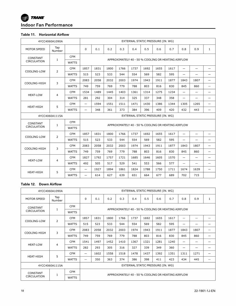
Table 11. Horizontal Airflow
4YCC4060A1090A EXTERNAL STATIC PRESSURE (IN. WG)
MOTOR SPEED TapNumber 0 0.1 0.2 0.3 0.4 0.5 0.6 0.7 0.8 0.9 1
CONSTANTCIRCULATION 1
CFMAPPROXIMATELY 40 - 50% COOLING OR HEATING AIRFLOW
WATTS
COOLING-LOW 2CFM 1857 1831 1800 1766 1737 1692 1655 1617 — — —
WATTS 515 523 533 544 554 569 582 595 — — —
COOLING-HIGH 3CFM 2083 2058 2032 2003 1974 1943 1911 1877 1843 1807 —
WATTS 749 759 769 779 788 803 816 830 845 860 —
HEAT-LOW 4CFM 1534 1489 1445 1403 1361 1314 1275 1234 — — —
WATTS 281 292 304 314 325 337 348 358 — — —
HEAT-HIGH 5CFM — 1594 1551 1511 1471 1430 1386 1344 1305 1265 —
WATTS — 348 361 373 384 396 409 420 432 443 —
4YCC4060A1115A EXTERNAL STATIC PRESSURE (IN. WG)
CONSTANTCIRCULATION 1
CFMAPPROXIMATELY 40 - 50% COOLING OR HEATING AIRFLOW
WATTS
COOLING-LOW 2CFM 1857 1831 1800 1766 1737 1692 1655 1617 — — —
WATTS 515 523 533 544 554 569 582 595 — — —
COOLING-HIGH 3CFM 2083 2058 2032 2003 1974 1943 1911 1877 1843 1807 —
WATTS 749 759 769 779 788 803 816 830 845 860 —
HEAT-LOW 4CFM 1827 1792 1757 1721 1685 1646 1605 1570 — — —
WATTS 492 505 517 529 541 553 566 577 — — —
HEAT-HIGH 5CFM — 1927 1894 1861 1824 1788 1750 1711 1674 1639 —
WATTS — 614 627 639 651 664 677 689 702 715
Table 12. Down Airflow
4YCC4060A1090A EXTERNAL STATIC PRESSURE (IN. WG)
MOTOR SPEED TapNumber 0 0.1 0.2 0.3 0.4 0.5 0.6 0.7 0.8 0.9 1
CONSTANTCIRCULATION 1
CFMAPPROXIMATELY 40 - 50% COOLING OR HEATING AIRFLOW
WATTS
COOLING-LOW 2CFM 1857 1831 1800 1766 1737 1692 1655 1617 — — —
WATTS 515 523 533 544 554 569 582 595 — — —
COOLING-HIGH 3CFM 2083 2058 2032 2003 1974 1943 1911 1877 1843 1807 —
WATTS 749 759 769 779 788 803 816 830 845 860 —
HEAT-LOW 4CFM 1541 1497 1452 1410 1367 1321 1281 1240 — — —
WATTS 282 293 305 316 327 339 349 360 — — —
HEAT-HIGH 5CFM — 1602 1558 1518 1478 1437 1392 1351 1311 1271 —
WATTS — 350 363 374 386 398 411 423 434 445 —
4YCC4060A1115A EXTERNAL STATIC PRESSURE (IN. WG)
CONSTANTCIRCULATION 1
CFMAPPROXIMATELY 40 - 50% COOLING OR HEATING AIRFLOW
WATTS
IInnddoooorr FFaann PPeerrffoorrmmaannccee
22-1901-1J-EN 19
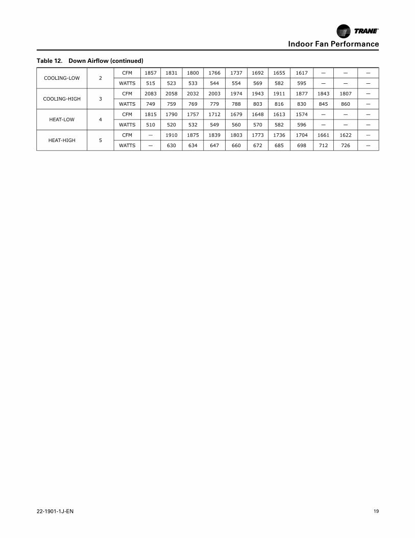
Table 12. Down Airflow (continued)
COOLING-LOW 2CFM 1857 1831 1800 1766 1737 1692 1655 1617 — — —
WATTS 515 523 533 544 554 569 582 595 — — —
COOLING-HIGH 3CFM 2083 2058 2032 2003 1974 1943 1911 1877 1843 1807 —
WATTS 749 759 769 779 788 803 816 830 845 860 —
HEAT-LOW 4CFM 1815 1790 1757 1712 1679 1648 1613 1574 — — —
WATTS 510 520 532 549 560 570 582 596 — — —
HEAT-HIGH 5CFM — 1910 1875 1839 1803 1773 1736 1704 1661 1622 —
WATTS — 630 634 647 660 672 685 698 712 726 —
IInnddoooorr FFaann PPeerrffoorrmmaannccee
20 22-1901-1J-EN
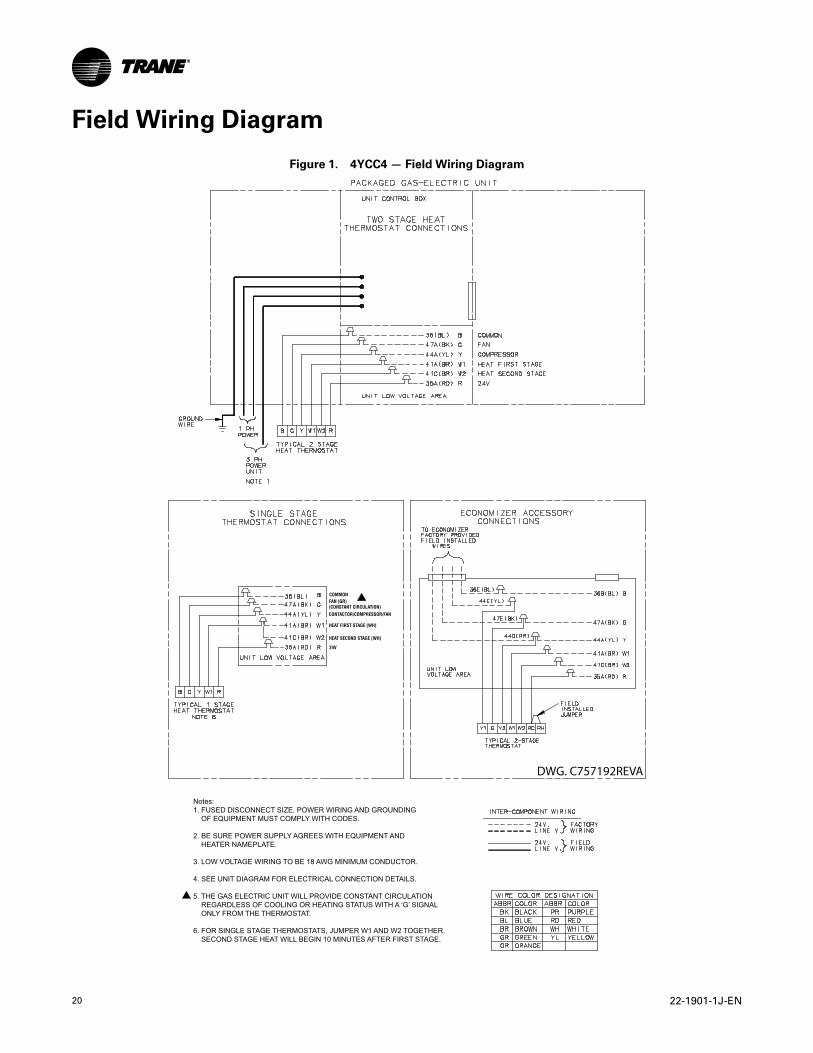
Field Wiring Diagram
Figure 1. 4YCC4 — Field Wiring Diagram
FAN (GR) (CONSTANT CIRCULATION)
COMMON
CONTACTOR/COMPRESSOR/FAN
HEAT FIRST STAGE (WH)
HEAT SECOND STAGE (WH)
24V
Notes:1. FUSED DISCONNECT SIZE, POWER WIRING AND GROUNDING OF EQUIPMENT MUST COMPLY WITH CODES.
2. BE SURE POWER SUPPLY AGREES WITH EQUIPMENT AND HEATER NAMEPLATE.
3. LOW VOLTAGE WIRING TO BE 18 AWG MINIMUM CONDUCTOR.
4. SEE UNIT DIAGRAM FOR ELECTRICAL CONNECTION DETAILS.
5. THE GAS ELECTRIC UNIT WILL PROVIDE CONSTANT CIRCULATION REGARDLESS OF COOLING OR HEATING STATUS WITH A ‘G’ SIGNAL ONLY FROM THE THERMOSTAT.
6. FOR SINGLE STAGE THERMOSTATS, JUMPER W1 AND W2 TOGETHER. SECOND STAGE HEAT WILL BEGIN 10 MINUTES AFTER FIRST STAGE.
DWG. C757192REVA
22-1901-1J-EN 21
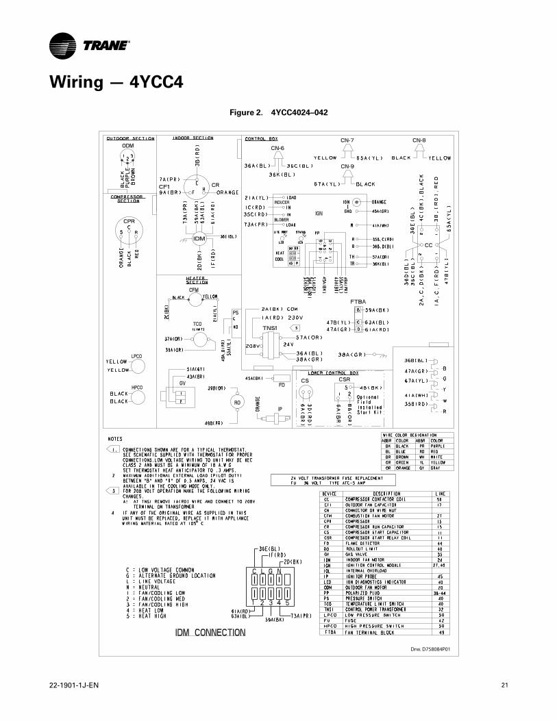
Wiring — 4YCC4
Figure 2. 4YCC4024–042
Drw. D758084P01
22 22-1901-1J-EN
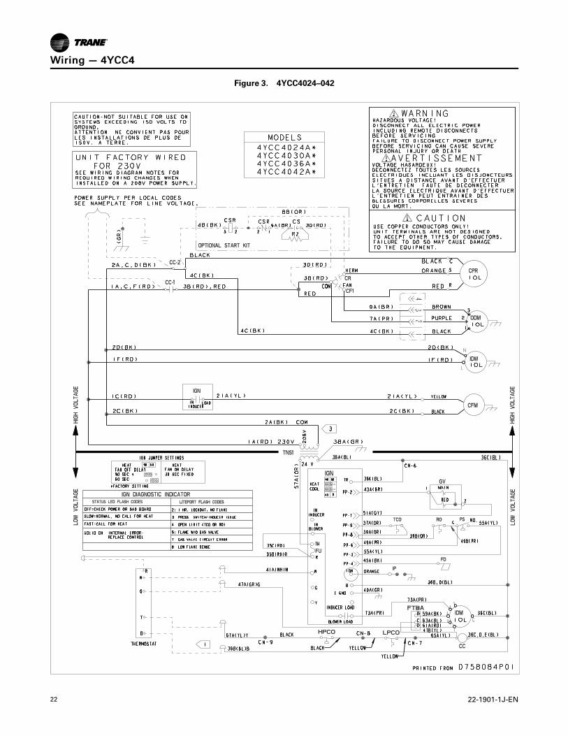
Figure 3. 4YCC4024–042
WWiirriinngg —— 44YYCCCC44
22-1901-1J-EN 23
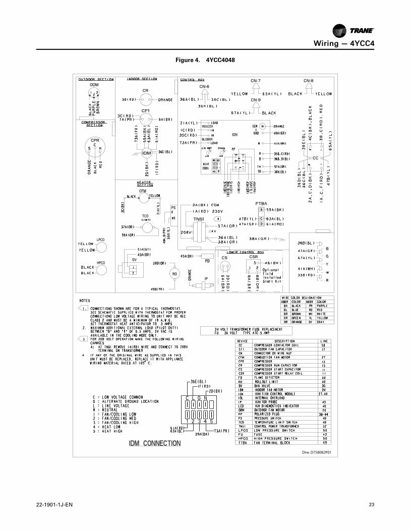
Figure 4. 4YCC4048
Drw. D758082P01
WWiirriinngg —— 44YYCCCC44
24 22-1901-1J-EN
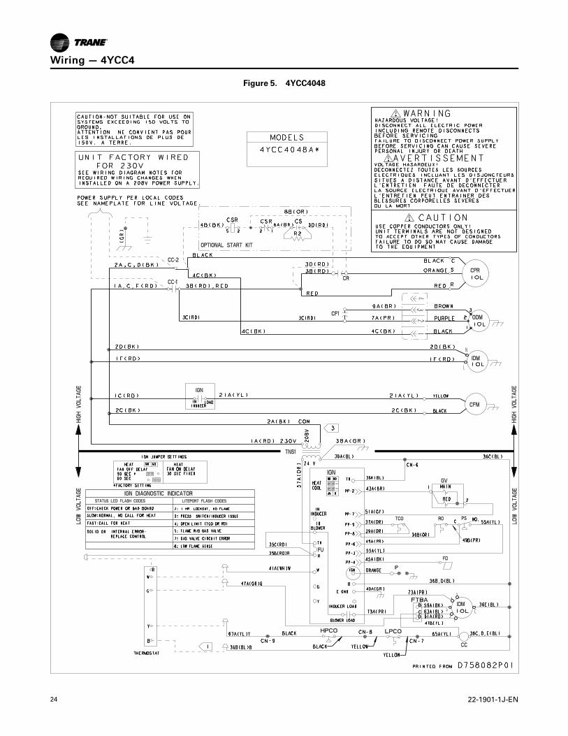
Figure 5. 4YCC4048
WWiirriinngg —— 44YYCCCC44
22-1901-1J-EN 25
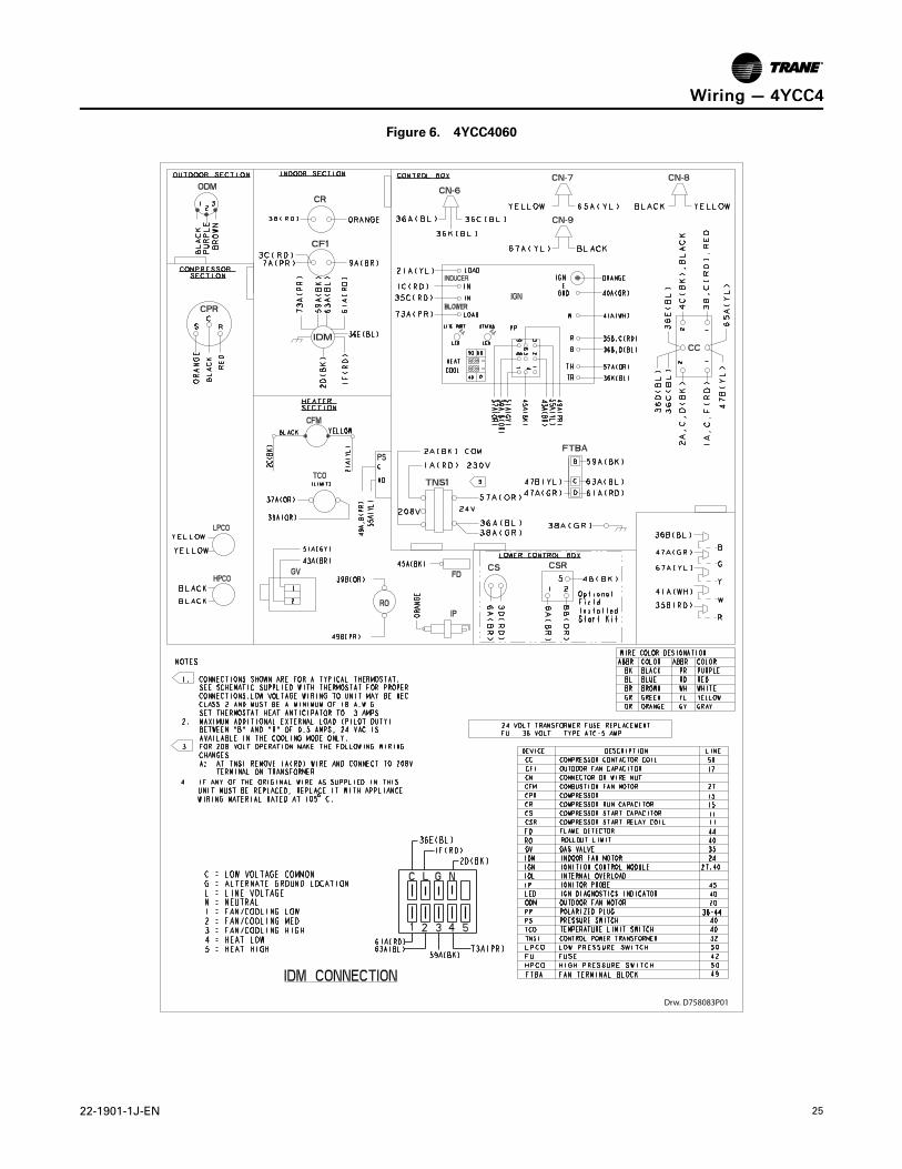
Figure 6. 4YCC4060
Drw. D758083P01
WWiirriinngg —— 44YYCCCC44

26 22-1901-1J-EN
Figure 7. 4YCC4060
WWiirriinngg —— 44YYCCCC44
22-1901-1J-EN 27
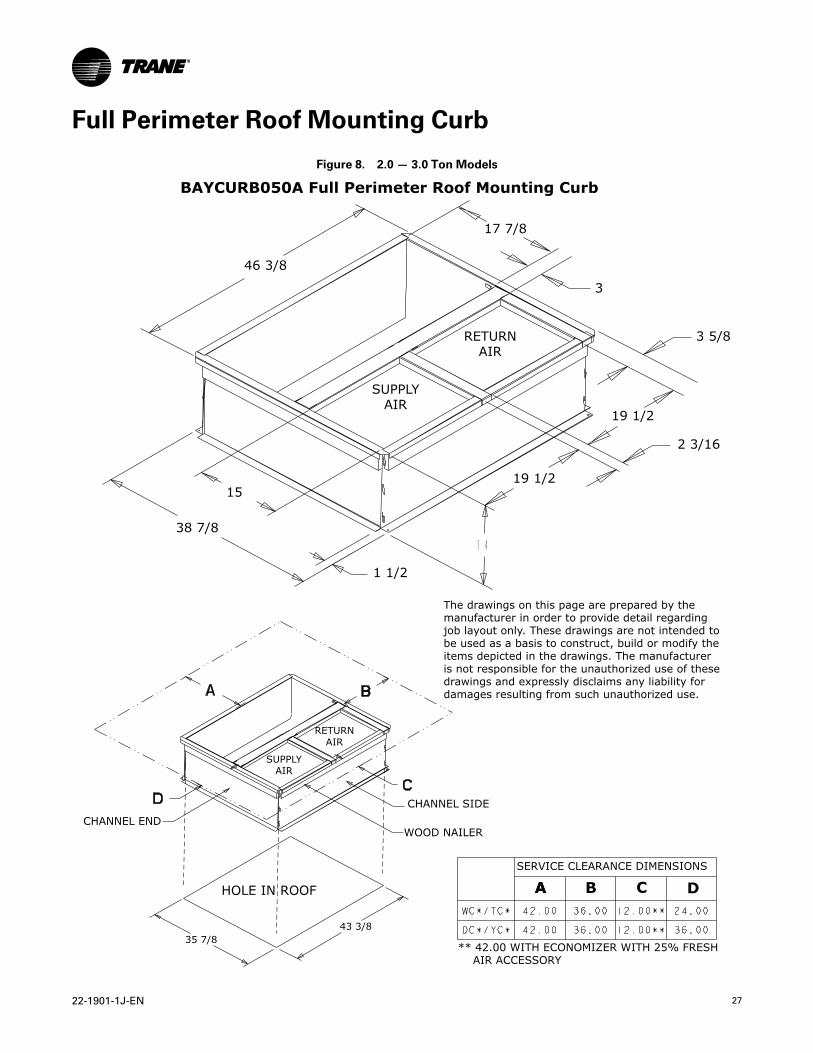
Full Perimeter Roof Mounting Curb
Figure 8. 2.0 — 3.0 Ton Models
A
SUPPLYAIR
RETURNAIR
SUPPLYAIR
RETURNAIR
CHANNEL SIDE
WOOD NAILER
HOLE IN ROOF
CHANNEL END
SERVICE CLEARANCE DIMENSIONS
A B C D
** 42.00 WITH ECONOMIZER WITH 25% FRESH AIR ACCESSORY
The drawings on this page are prepared by themanufacturer in order to provide detail regardingjob layout only. These drawings are not intended tobe used as a basis to construct, build or modify theitems depicted in the drawings. The manufactureris not responsible for the unauthorized use of thesedrawings and expressly disclaims any liability fordamages resulting from such unauthorized use.
BAYCURB050A Full Perimeter Roof Mounting Curb
46 3/8
17 7/8
3
15
38 7/8
3 5/8
19 1/2
2 3/16
19 1/2
1 1/2
35 7/843 3/8
28 22-1901-1J-EN
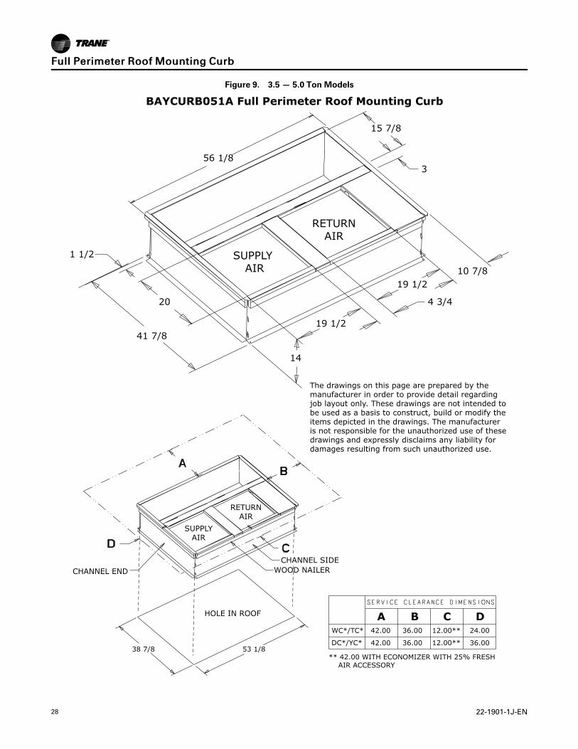
Figure 9. 3.5 — 5.0 Ton Models
The drawings on this page are prepared by themanufacturer in order to provide detail regardingjob layout only. These drawings are not intended tobe used as a basis to construct, build or modify theitems depicted in the drawings. The manufactureris not responsible for the unauthorized use of thesedrawings and expressly disclaims any liability fordamages resulting from such unauthorized use.
SUPPLYAIR
RETURNAIR
CHANNEL SIDEWOOD NAILER
HOLE IN ROOF
CHANNEL END
WC*/TC*
DC*/YC*
12.00**
12.00**42.00
42.00
36.00
36.00
36.00
24.00
** 42.00 WITH ECONOMIZER WITH 25% FRESH AIR ACCESSORY
A B DC
SUPPLY AIR
RETURNAIR
BAYCURB051A Full Perimeter Roof Mounting Curb
56 1/8
15 7/8
3
1 1/2
10 7/819 1/2
19 1/2
4 3/4
14
20
41 7/8
38 7/8 53 1/8
FFuullll PPeerriimmeetteerr RRooooff MMoouunnttiinngg CCuurrbb
22-1901-1J-EN 29
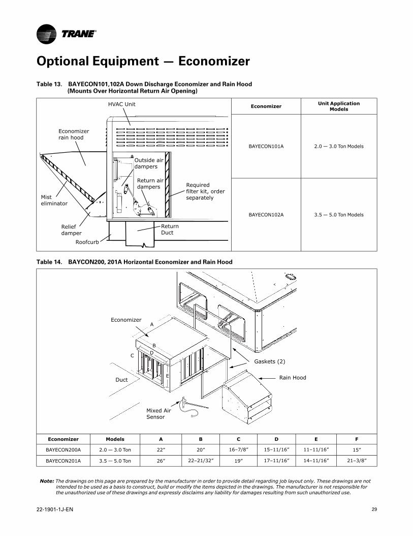
Optional Equipment — Economizer
Table 13. BAYECON101,102A Down Discharge Economizer and Rain Hood(Mounts Over Horizontal Return Air Opening)
HVAC Unit
Economizerrain hood
Outside airdampers
Return airdampers Required
filter kit, orderseparately
ReturnDuct
Roofcurb
Reliefdamper
Mist eliminator
Economizer Unit ApplicationModels
BAYECON101A 2.0 — 3.0 Ton Models
BAYECON102A 3.5 — 5.0 Ton Models
Table 14. BAYCON200, 201A Horizontal Economizer and Rain Hood
Economizer
Gaskets (2)
Rain Hood
Mixed AirSensor
Duct
A
B
C D
E
Economizer Models A B C D E F
BAYECON200A 2.0 — 3.0 Ton 22” 20” 16–7/8” 15–11/16” 11–11/16” 15”
BAYECON201A 3.5 — 5.0 Ton 26” 22–21/32” 19” 17–11/16” 14–11/16” 21–3/8”
Note: The drawings on this page are prepared by the manufacturer in order to provide detail regarding job layout only. These drawings are notintended to be used as a basis to construct, build or modify the items depicted in the drawings. The manufacturer is not responsible forthe unauthorized use of these drawings and expressly disclaims any liability for damages resulting from such unauthorized use.
30 22-1901-1J-EN
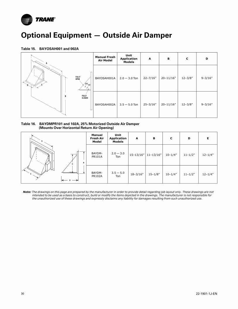
Optional Equipment — Outside Air Damper
Table 15. BAYOSAH001 and 002A
A
D C
B
FULLY OPEN
FULLY CLOSED
2/31/3
Manual FreshAir Model
UnitApplicationModels
A B C D
BAYOSAH001A 2.0 — 3.0 Ton 22–7/16” 20–11/16” 12–3/8” 9–3/16”
BAYOSAH002A 3.5 — 5.0 Ton 25–3/16” 20–11/16” 12–3/8” 9–3/16”
Table 16. BAYDMPR101 and 102A, 25% Motorized Outside Air Damper(Mounts Over Horizontal Return Air Opening)
A
E
BC
D
ManualFresh AirModel
UnitApplicationModels
A B C D E
BAYDM-PR101A
2.0 — 3.0Ton 15–13/16” 11–13/16” 10–1/4” 11–1/2” 12–1/4”
BAYDM-PR102A
3.5 — 5.0Ton 18–3/16” 15–1/8” 10–1/4” 11–1/2” 12–1/4”
Note: The drawings on this page are prepared by the manufacturer in order to provide detail regarding job layout only. These drawings are notintended to be used as a basis to construct, build or modify the items depicted in the drawings. The manufacturer is not responsible forthe unauthorized use of these drawings and expressly disclaims any liability for damages resulting from such unauthorized use.
22-1901-1J-EN 31
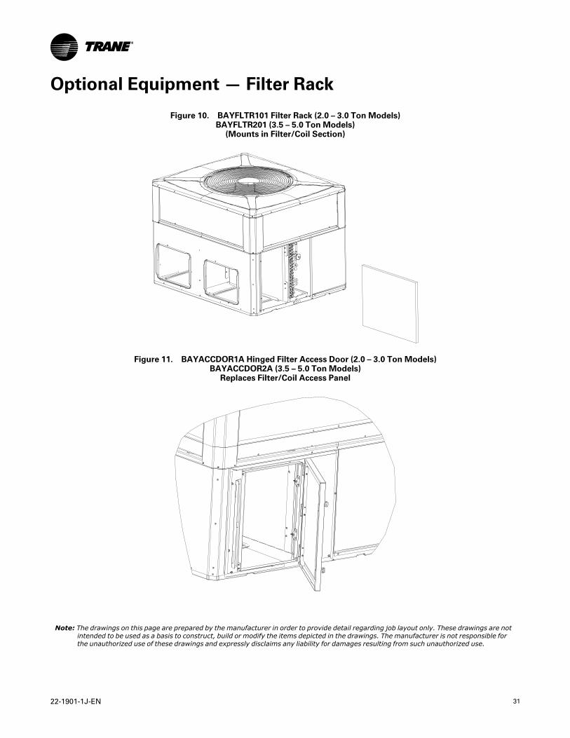
Optional Equipment — Filter Rack
Figure 10. BAYFLTR101 Filter Rack (2.0 – 3.0 Ton Models)BAYFLTR201 (3.5 – 5.0 Ton Models)
(Mounts in Filter/Coil Section)
Figure 11. BAYACCDOR1A Hinged Filter Access Door (2.0 – 3.0 Ton Models)BAYACCDOR2A (3.5 – 5.0 Ton Models)
Replaces Filter/Coil Access Panel
Note: The drawings on this page are prepared by the manufacturer in order to provide detail regarding job layout only. These drawings are notintended to be used as a basis to construct, build or modify the items depicted in the drawings. The manufacturer is not responsible forthe unauthorized use of these drawings and expressly disclaims any liability for damages resulting from such unauthorized use.
32 22-1901-1J-EN
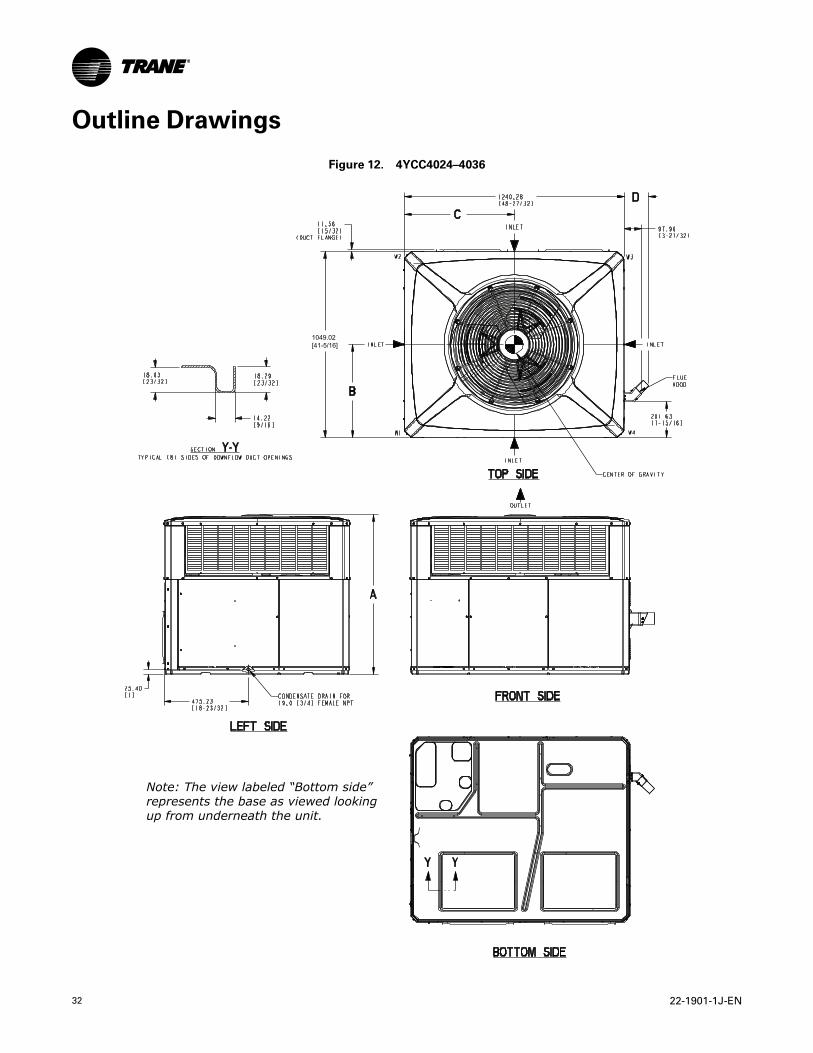
Outline Drawings
Figure 12. 4YCC4024–4036
Note: The view labeled “Bottom side”represents the base as viewed lookingup from underneath the unit.
1049.02[41-5/16]
22-1901-1J-EN 33
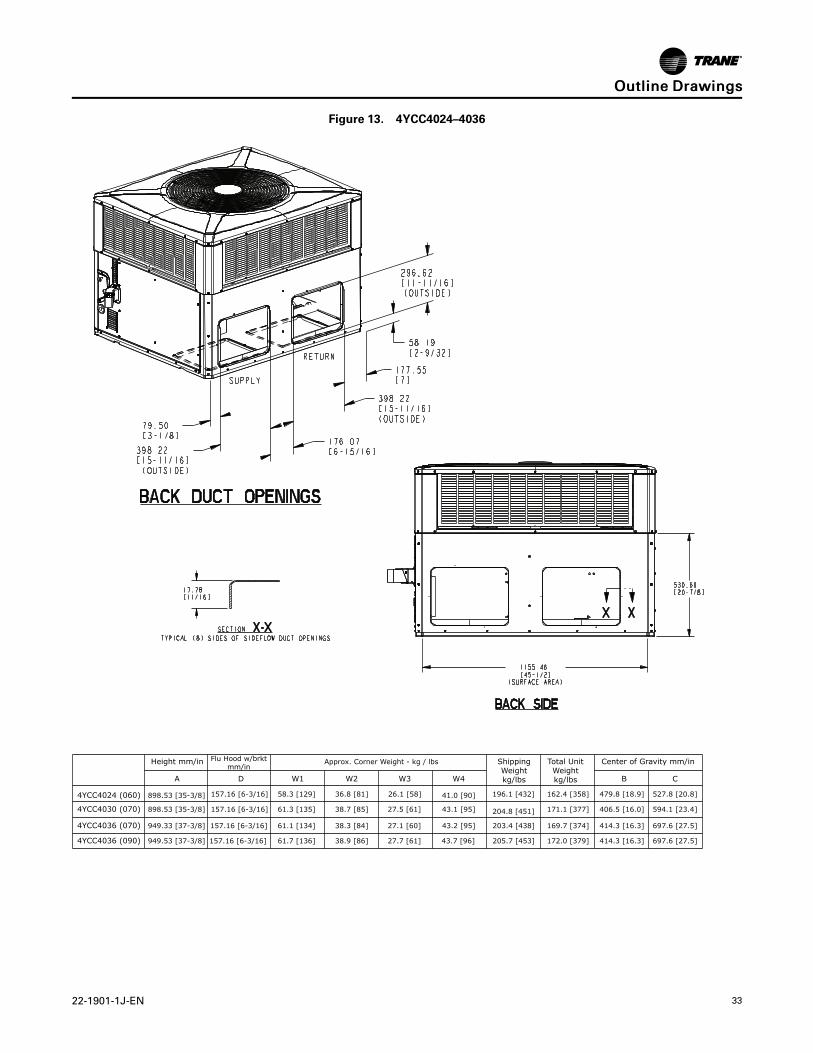
Figure 13. 4YCC4024–4036
BA C
4YCC4024 (060)
4YCC4030 (070)
4YCC4036 (070)
4YCC4036 (090)
Height mm/in Flu Hood w/brktmm/in
Approx. Corner Weight - kg / lbs
D W1 W2 W3 W4
ShippingWeightkg/lbs
Total UnitWeightkg/lbs
Center of Gravity mm/in
898.53 [35-3/8]
898.53 [35-3/8]
949.33 [37-3/8]
949.53 [37-3/8]
157.16 [6-3/16]
157.16 [6-3/16]
157.16 [6-3/16]
58.3 [129]
61.3 [135]
61.1 [134]
61.7 [136]
36.8 [81]
38.7 [85]
38.3 [84]
38.9 [86]
26.1 [58]
27.5 [61]
27.1 [60]
27.7 [61]
41.0 [90]
43.1 [95]
43.2 [95]
43.7 [96]
196.1 [432]
204.8 [451]
203.4 [438]
205.7 [453]
479.8 [18.9]162.4 [358]
171.1 [377]
169.7 [374]
172.0 [379]
406.5 [16.0]
414.3 [16.3]
414.3 [16.3]
527.8 [20.8]
594.1 [23.4]
697.6 [27.5]
697.6 [27.5]
157.16 [6-3/16]
OOuuttlliinnee DDrraawwiinnggss
34 22-1901-1J-EN
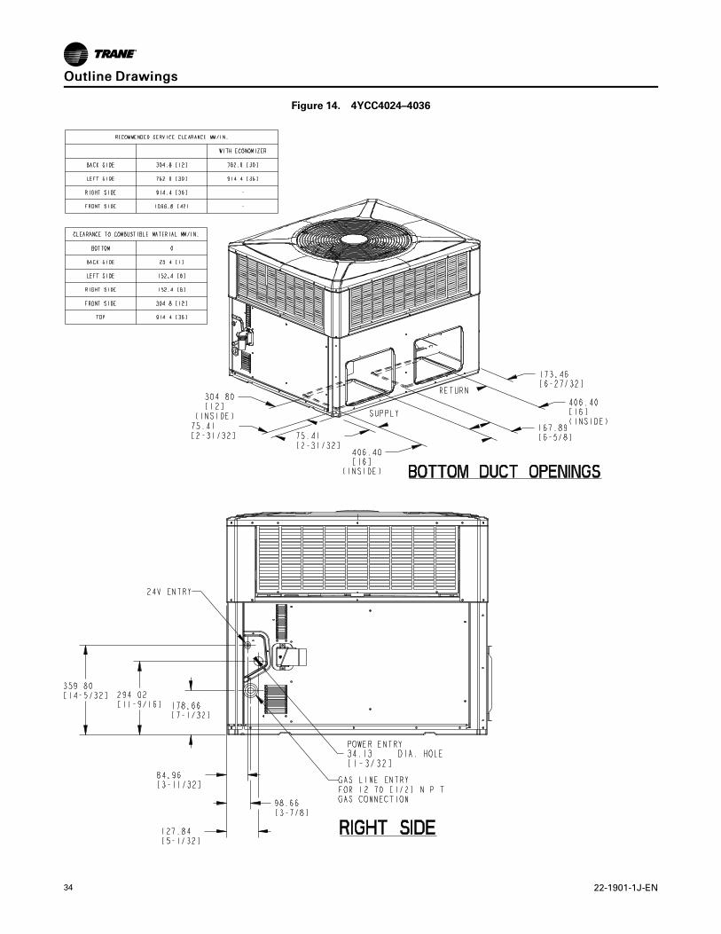
Figure 14. 4YCC4024–4036
OOuuttlliinnee DDrraawwiinnggss
22-1901-1J-EN 35
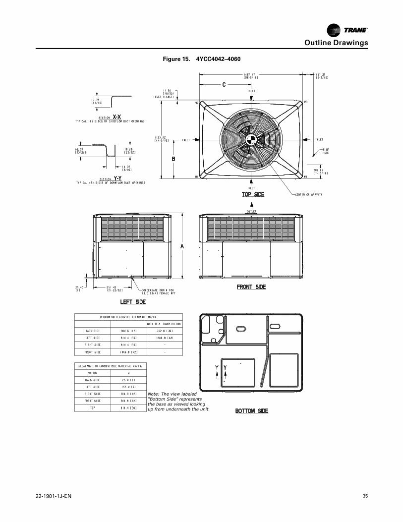
Figure 15. 4YCC4042–4060
Note: The view labeled“Bottom Side” representsthe base as viewed lookingup from underneath the unit.
OOuuttlliinnee DDrraawwiinnggss
36 22-1901-1J-EN
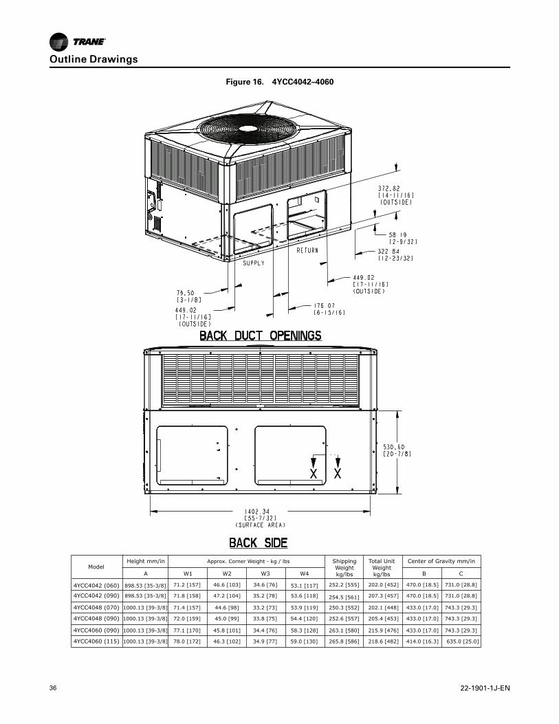
Figure 16. 4YCC4042–4060
BA C
4YCC4042 (060)
4YCC4042 (090)
4YCC4048 (070)
4YCC4048 (090)
Height mm/in Approx. Corner Weight - kg / lbs
W1 W2 W3 W4
ShippingWeightkg/lbs
Total UnitWeightkg/lbs
Center of Gravity mm/in
898.53 [35-3/8]
898.53 [35-3/8]
71.2 [157]
71.8 [158]
71.4 [157]
72.0 [159]
46.6 [103]
47.2 [104]
44.6 [98]
45.0 [99]
34.6 [76]
35.2 [78]
33.2 [73]
33.8 [75]
53.1 [117]
53.6 [118]
53.9 [119]
54.4 [120]
252.2 [555]
254.5 [561]
250.3 [552]
252.6 [557]
470.0 [18.5]202.0 [452]
207.3 [457]
202.1 [448]
205.4 [453]
470.0 [18.5]
433.0 [17.0]
433.0 [17.0]
731.0 [28.8]
731.0 [28.8]
743.3 [29.3]
743.3 [29.3]
4YCC4060 (090)
4YCC4060 (115)
1000.13 [39-3/8]
1000.13 [39-3/8]
77.1 [170]
78.0 [172]
45.8 [101]
46.3 [102]
34.4 [76]
34.9 [77]
58.3 [128]
59.0 [130]
263.1 [580]
265.8 [586]
215.9 [476]
218.6 [482]
433.0 [17.0]
414.0 [16.3]
743.3 [29.3]
635.0 [25.0]
Model
1000.13 [39-3/8]
1000.13 [39-3/8]
OOuuttlliinnee DDrraawwiinnggss
22-1901-1J-EN 37
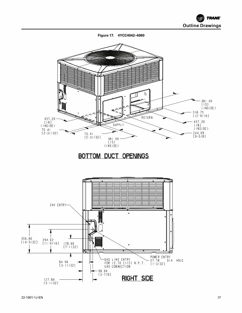
Figure 17. 4YCC4042–4060
OOuuttlliinnee DDrraawwiinnggss

38 22-1901-1J-EN
NNootteess

22-1901-1J-EN 39
NNootteess
Trane - by Trane Technologies (NYSE: TT), a global innovator - creates comfortable, energy efficient indoorenvironments for commercial and residential applications. For more information, please visit trane. com ortranetechnologies.com.
The AHRI Certified mark indicates Trane U.S. Inc. participation in the AHRI Certification program. For verification of individual certified products, go to ahridirectory.org.
Trane has a policy of continuous data improvement and it reserves the right to change design and specifications without notice. We are committed to usingenvironmentally conscious print practices.
22-1901-1J-EN 01 Jun 2020
Supersedes 22-1901-1H-EN (June 2019) ©2020 Trane