ROOFT@IR - c-o-k.ru
68
Roof-mouted air conditioning unit Unite d'air conditionne de toiture Dachklimagerät Uunità d’aria condizionata da tetto Unidad da aire acondicionado de tejado English IOM RT 04-N-2ALL Part number / Code / Teil Nummer / Codice / Código : 3990475 Supersedes / Annule et remplace / Annulliert und ersetzt / Annulla e sostituisce / Anula y sustituye : IOM RT 04-N-1ALL Français 40 108 kW 38 107 kW Español Deutsch Italiano Installation and maintenance manual Manuel d’installation et de maintenance Installations- und Wartungshandbuch Manuale di installazione e di manutenzione Manual de instalación y de mantenimiento ROOFT@IR 40 ÷ 110 Библиотека СОК
Transcript of ROOFT@IR - c-o-k.ru
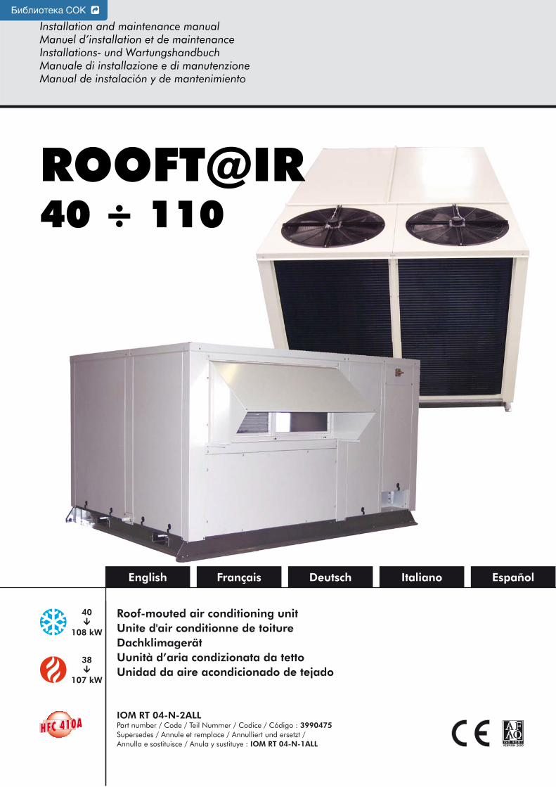
Roof-mouted air conditioning unitUnite d'air conditionne de toitureDachklimagerätUunità d’aria condizionata da tettoUnidad da aire acondicionado de tejado
English
IOM RT 04-N-2ALLPart number / Code / Teil Nummer / Codice / Código : 3990475Supersedes / Annule et remplace / Annulliert und ersetzt / Annulla e sostituisce / Anula y sustituye : IOM RT 04-N-1ALL
Français
40�
108 kW
38�
107 kW
EspañolDeutsch Italiano
Installation and maintenance manualManuel d’installation et de maintenanceInstallations- und WartungshandbuchManuale di installazione e di manutenzioneManual de instalación y de mantenimiento
ROOFT@IR40 ÷ 110
Библиотека СОК

INSTALLATION INSTRUCTION
NOTICE D’INSTALLATION
INSTALLATIONSHANDBUCH
ISTRUZIONI INSTALLAZIONE
INSTRUCCIONES DE INSTALACIÓN
2
CONTENTSGENERAL RECOMMENDATIONS ...............................................................................................................3
SAFETY DIRECTIONS ................................................................................................................................................................ 3WARNING ............................................................................................................................................................................... 3EQUIPMENT SAFETY DATA ....................................................................................................................................................... 4
INSPECTION AND STORAGE .....................................................................................................................5WARRANTY ...............................................................................................................................................5CONTENTS OF PACKAGE ..........................................................................................................................5PRESENTATION .........................................................................................................................................5TECHNICAL SPECIFICATIONS ....................................................................................................................6DIMENSIONS ............................................................................................................................................6HANDLING ...............................................................................................................................................6
NET WEIGHT ........................................................................................................................................................................... 7CENTRE OF GRAVITY IN RELATION TO UNIT DIMENSIONS ....................................................................................................... 7
ELECTRICAL SPECIFICATIONS ...................................................................................................................8UNIT WITHOUT HEATING ........................................................................................................................................................ 8UNIT WITH HEATING TYPE CH1 ............................................................................................................................................... 8UNIT WITH HEATING TYPE CH2 ............................................................................................................................................... 8
INSTALLATION ..........................................................................................................................................8PLACE OF INSTALLATION AND REQUIREMENTS ........................................................................................................................ 8CLEARANCE ............................................................................................................................................................................ 9UNIT LOCATION ..................................................................................................................................................................... 9ATTACHMENT TO THE GROUND ............................................................................................................................................ 9CONDENSATE DRAIN PAIN ...................................................................................................................................................... 9ROOF CURB .......................................................................................................................................................................... 10
ROOF CURB DIMENSIONS ...................................................................................................................................................................... 10
CONFIGURATION OF THE UNIT .............................................................................................................11GENERALITES......................................................................................................................................................................... 11SUPPLY AIR............................................................................................................................................................................. 11AIR INTAKE ............................................................................................................................................................................ 11
ECONOMISER .........................................................................................................................................12ELECTRIC HEAT .......................................................................................................................................12WIRING DIAGRAM AND LEGEND ............................................................................................................13
WIRING DIAGRAM ................................................................................................................................................................. 13LEGEND ................................................................................................................................................................................ 13
POWER SUPPLY ........................................................................................................................................................................................ 13WIRING DIAGRAM KEY DESCRIPTIONS .................................................................................................................................................... 13
POWER SUPPLY DIAGRAMS: ............................................................................................................................................................................................. 13CONTROL AND REGULATION DIAGRAMS ........................................................................................................................................................................ 14
RANGE AND SETTINGS OF THEMAL PROTECTION / NOMINAL INTENSITY OF THE CONTACTORS (CLASSE AC3) ..................................... 15COMPRESSORS CRANKCASE HEATER ....................................................................................................................................................... 15PRESSOSTATS SETTING ........................................................................................................................................................................... 15
ELECTRICAL CONNECTIONS ...................................................................................................................16COMMISSIONING ...................................................................................................................................18
PRE-START CHECK LIST ........................................................................................................................................................... 18ELECTRICAL CHECK ................................................................................................................................................................................. 18VISUAL CHECK ........................................................................................................................................................................................ 18DUCTING ................................................................................................................................................................................................ 18AIR BALANCING ...................................................................................................................................................................................... 19
CASE N°1: ....................................................................................................................................................................................................................... 19CASE N°2: ....................................................................................................................................................................................................................... 19
OPERATING CHECK LIST ........................................................................................................................................................ 20GENERAL................................................................................................................................................................................................. 20PHASE ROTATION PROTECTION ............................................................................................................................................................. 20ELECTRICAL ............................................................................................................................................................................................. 20
SET POINTS ..................................................................................................................................................................................................................... 20OPERATING VOLTAGE: .................................................................................................................................................................................................... 20CONTROL ....................................................................................................................................................................................................................... 20
BLOWER & DRIVE ..................................................................................................................................................................................... 20COMPRESSOR AND REFRIGERATION SYSTEM .......................................................................................................................................... 20FINAL CHECK .......................................................................................................................................................................................... 21
FINAL TASKS ...........................................................................................................................................21IN CASE OF WARRANTY - MATERIAL RETURN PROCEDURE ....................................................................21ORDERING SERVICE AND SPARE PARTS ORDER ......................................................................................21MAINTENANCE .......................................................................................................................................21
REGULAR MAINTENANCE ...................................................................................................................................................... 21GENERAL INSPECTION .......................................................................................................................................................... 21OPENING OF ACCESS PANELS .............................................................................................................................................. 22BLOWER DRIVE SYSTEM ......................................................................................................................................................... 22COILS ................................................................................................................................................................................... 22ELECTRICAL SECTION ............................................................................................................................................................ 22SERVICING CHECKLIST .......................................................................................................................................................... 23
TROUBLE SHOOTING ..............................................................................................................................24
3
POWER SUPPLY MUST BE SWITCHED OFF
BEFORE STARTING TOWORK IN THE ELECTRIC
CONTROL BOX
GENERAL RECOMMENDATIONSPlease read the following safety precautions very carefully before installing the unit.
SAFETY DIRECTIONS
Follow the safety rules in forces when you are working on your appliance.
The installation, commissioning and maintenance of these units should be performed by qualified personnel having a good knowledge of standards and local regulations, as well as experience of this type of equipment.
Given the requirements of pressurising the system and the high current draws involved, this roof-mounted air conditioning should only be installed by qualified personnel.
The unit should be handled using lifting and handling equipment appropriate to the unit's size and weight.
Given the high refrigerant temperatures present at certain points in the cooling circuit, access to the area protected by the panels is strictly reserved for qualified personnel only. These panels are easily opened with a special tool. This tool should be kept by the installers or by the maintenance company.
Any wiring produced on site must comply with the corresponding national electrical regulations.
Make sure that the power supply and its frequency are adapted to the required electric current of operation, taking into account specific conditions of the location and the current required for any other appliance connected with the same circuit.
The unit must be EARTHED to avoid any risks caused by insulation defects.
It is forbidden to start any work on the electrical components if water or high humidity is present on the installation site.
WARNING
Cutoff power supply before starting to work on the appliance.
When making the hydraulic connections, ensure that no impurities are introduced into the pipe work.
The manufacturer declines any responsibility and the warrantly becomes void if these instructions are not respected.
If you meet a problem, please call the Technical Department of your area.
If possible, assemble the compulsory or optional accessories before placing the appliance on its final location. (see instructions provided with each accessory).
In order to become fully familiar with the appliance, we suggest to read also our Technical Instructions.
-The informations contained in these Instructions are subject to modification without advance notice.
4
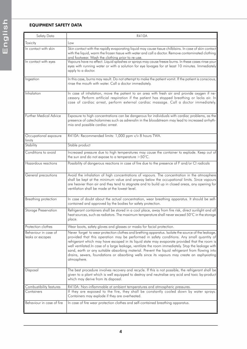
EQUIPMENT SAFETY DATA
Safety Data R410A
Toxicity Low
In contact with skin Skin contact with the rapidly evaporating liquid may cause tissue chilblains. In case of skin contact with the liquid, warm the frozen tissue with water and call a doctor. Remove contaminated clothing and footwear. Wash the clothing prior to re-use.
In contact with eyes Vapours have no effect. Liquid splashes or sprays may cause freeze burns. In these cases rinse your eyes with running water or with a solution for eye lavages for at least 10 minutes. Immediately apply to a doctor.
Ingestion In this case, burns may result. Do not attempt to make the patient vomit. If the patient is conscious, rinse the mouth with water. Call a doctor immediately.
Inhalation In case of inhalation, move the patient to an area with fresh air and provide oxygen if ne-cessary. Perform artificial respiration if the patient has stopped breathing or lacks air. In case of cardiac arrest, perform external cardiac massage. Call a doctor immediately.
Further Medical Advice Exposure to high concentrations can be dangerous for individuals with cardiac problems, as the presence of catecholamines such as adrenalin in the bloodstream may lead to increased arrhyth-mia and possible cardiac arrest.
Occupational exposure limits
R410A: Recommended limits: 1,000 ppm v/v 8 hours TWA.
Stability Stable product
Conditions to avoid Increased pressure due to high temperatures may cause the container to explode. Keep out of the sun and do not expose to a temperature >50°C.
Hazardous reactions Possibility of dangerous reactions in case of fire due to the presence of F and/or CI radicals
General precautions Avoid the inhalation of high concentrations of vapours. The concentration in the atmosphere shall be kept at the minimum value and anyway below the occupational limits. Since vapours are heavier than air and they tend to stagnate and to build up in closed areas, any opening for ventilation shall be made at the lowest level.
Breathing protection In case of doubt about the actual concentration, wear breathing apparatus. It should be self-contained and approved by the bodies for safety protection.
Storage Preservation Refrigerant containers shall be stored in a cool place, away from fire risk, direct sunlight and all heat sources, such as radiators. The maximum temperature shall never exceed 50°C in the storage place.
Protection clothes Wear boots, safety gloves and glasses or masks for facial protection.
Behaviour in case of leaks or escapes
Never forget to wear protection clothes and brething apparatus. Isolate the source of the leakage, provided that this operation may be performed in safety conditions. Any small quantity of refrigerant which may have escaped in its liquid state may evaporate provided that the room is well ventilated.In case of a large leakage, ventilate the room immediately. Stop the leakage with sand, earth or any suitable absorbing material. Prevent the liquid refrigerant from flowing into drains, sewers, foundations or absorbing wells since its vapours may create an asphyxiating atmosphere.
Disposal The best procedure involves recovery and recycle. If this is not possible, the refrigerant shall be given to a plant which is well equipped to destroy and neutralise any acid and toxic by-product which may derive from its disposal.
Combustibility features R410A: Non-inflammable at ambient temperatures and atmospheric pressures.Containers If they are exposed to the fire, they shall be constantly cooled down by water sprays.
Containers may explode if they are overheated.
Behaviour in case of fire In case of fire wear protection clothes and self-contained breathing apparatus.
5
INSPECTION AND STORAGEAt the time of receiving the equipment carefully cross check all the elements against the shipping documents in order to ensure that all the crates and boxes have been received. Confirmation of the type of unit ordered can be obtained by reading the maker’s plate (capacity, type and air blowing configuration).
Inspect the units for any visible or hidden damage.
In the event of shipping damage, write precise details of the damage on the shipper’s delivery note and send immediately a registered letter to the shipper within 48 hours, clearly stating the damage caused. Forward a copy of this letter to the manufacturer or their representative.
Never store or transport the unit upside down. Protect unit at the job side from domages made by others. When unit is stored on the ground, avoid mud store unit leveled.
CONTENTS OF PACKAGE1 Rooft@ir
1 Installation and maintenance manual
1 Control manual
WARRANTYThe appliances are delivered fully assembled, factory tested and ready to operate.
Any modification to the units without the manufacturer’s prior approval, shall automatically render the warranty null and void.
The following conditions must be respected in order to maintain the validity of the warranty:
Commissioning shall be performed by specialised technicians from technical services approved by �the manufacturer.
Maintenance shall be performed by technicians trained for this purpose. �
Only Original Equipment spare parts shall be used. �
All the operations listed in the present manual shall be performed within the prescribed schedule. �
THE WARRANTY SHALL BE NULL AND VOID IN THE EVENT OF NON-COMPLIANCE WITH ANY OF THE ABOVE CONDITIONS.
PRESENTATIONThe machine has been designed for an outdoor mouted application, ensuring perfectly weatherproof circulation of the air within the compartments.
The RT is design very compact and it has an optimal foot print/weight ratio. Numerous accessoires and options can be added to the basic version to adapt it perfectly to the client’s specific requirements. All units are charged and tested at the factory and are supplied ready to start for quick and easy commissioning.
INSTRUCTIONS FOR FILLING IN THE "1st START-UP FORM"
(SEE APPENDIX)
It is the responsibility of the OWNER to make sure that the "1st Start-up Form" is fully filled in by the authorized Service Centre and sent by registered mail - notified in advance by fax - to the After-Sales Service of the constructor within 8 days of the initial start-up.
Failure to receive the form on the part of the constructor will render the guarantee null and void.
6
DIMENSIONS
HANDLING
SEE APPENDIX
TECHNICAL SPECIFICATIONS
You can adjust the available static pressure and flow by adjusting the variable motor pulley fitted to the blower (SEE AIR BALANCING).
Forks guiderails are supplied as standard with the machine irrespective of the air configuration. They enable the machine to be moved without damaging its base or casing.
I n t h e case of a downward air configuration, remember to remove the forks guiderails before lifting the unit to install it on the roof curb.
900 A
80,5
0
170
MINIMUM FORK LENGTH: 2M
FORKS GUIDERAILS
Models 40 50 60 70 80 100 110
Compressor typeScroll
TandemScroll
TandemScroll Scroll Scroll Scroll Scroll
Compressor quantity 2 2 2 2 2 2 2Number of circuit 1 1 2 2 2 2 2Refrigerant R410ACharge of circuit kg SEE NAME PLATENumber of blower 1 1 1 1 1 1 1Type CentrifugalNominal indoor airflow m3/h 7 650 9 200 11 500 12 500 16 500 18 650 20 000Number of outdoor fans 2 2 4 4 4 2 2Type HelicoidNominal external total airflow m3/h 16 000 16 000 32 000 32 000 32 000 34 000 34 000
40-50 60-110
A 478 651
LIFTING WITH THE FORKS GUIDERAILS OBLIGATORY
7
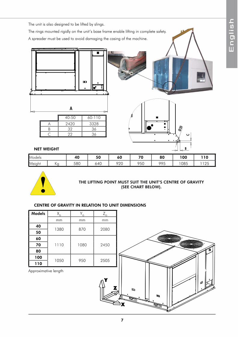
NET WEIGHT
THE LIFTING POINT MUST SUIT THE UNIT’S CENTRE OF GRAVITY (SEE CHART BELOW).
CENTRE OF GRAVITY IN RELATION TO UNIT DIMENSIONS
X
Y
Z
B
C
Ø30
A
Models 40 50 60 70 80 100 110
Weight Kg 580 640 920 950 995 1085 1125
Models XG YG ZG
mm mm mm
401380 870 2080
50
60
1110 1080 245070
80
1001050 950 2505
110
Approximative length
The unit is also designed to be lifted by slings.
The rings mounted rigidly on the unit’s base frame enable lifting in complete safety.
A spreader must be used to avoid damaging the casing of the machine.
40-50 60-110
A 2420 3328B 32 36C 22 36
8
INSTALLATION
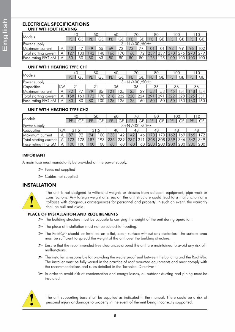
ELECTRICAL SPECIFICATIONS
IMPORTANT
A main fuse must mandatorily be provided on the power supply.
Fuses not supplied �
Cables not supplied �
The unit is not designed to withstand weights or stresses from adjacent equipment, pipe work or constructions. Any foreign weight or stress on the unit structure could lead to a malfunction or a collapse with dangerous consequences for personnel and property. In such an event, the warranty shall be null and avoid.
The unit supporting base shall be supplied as indicated in the manual. There could be a risk of personal injury or damage to property in the event of the unit being incorrectly supported.
The building structure must be capable to carrying the weight of the unit during operation. �
The place of installation must not be subject to flooding. �
The Rooft@ir should be installed on a flat, clean surface without any obstacles. The surface area �must be sufficient to spread the weight of the unit over the building structure.
Ensure that the recommended free clearances around the unit are maintained to avoid any risk of �malfunctions.
The installer is responsible for providing the weaterproof seal between the building and the Rooft@ir. �The installer must be fully versed in the practice of roof mounted equipments and must comply with the recommendations and rules detailed in the Technical Directives.
In order to avoid risk of condensation and energy losses, all outdoor ducting and piping must be �insulated.
UNIT WITHOUT HEATING
UNIT WITH HEATING TYPE CH1
PLACE OF INSTALLATION AND REQUIREMENTS
UNIT WITH HEATING TYPE CH2
Models 40 50 60 70 80 100 110PE GE PE GE PE GE PE GE PE GE PE GE PE GE
Power supply 3+N /400 /50HzMaximum current A 42 47 49 55 69 73 73 77 101 101 93 99 96 102Total starting current A 127 133 142 148 166 170 168 172 239 239 270 276 273 279Fuse rating FFG aM A 50 50 50 63 80 80 80 80 125 125 100 100 100 100
Models 40 50 60 70 80 100 110PE GE PE GE PE GE PE GE PE GE PE GE PE GE
Power supply 3+N /400 /50HzCapacities KW 21 21 36 36 36 36 36Maximum current A 72 77 79 85 121 125 125 129 153 153 145 151 148 154Total starting current A 158 163 172 178 218 222 220 224 291 291 322 328 325 331Fuse rating FFG aM A 80 80 80 100 125 125 125 160 160 160 160 160 160 160
Models 40 50 60 70 80 100 110PE GE PE GE PE GE PE GE PE GE PE GE PE GE
Power supply 3+N /400 /50HzCapacities KW 31.5 31.5 48 48 48 48 48Maximum current A 87 92 94 100 138 142 142 146 170 170 162 169 165 172Total starting current A 173 178 187 193 235 239 237 241 308 308 339 346 342 349Fuse rating FFG aM A 100 100 100 100 160 160 160 160 200 200 200 200 200 200
9
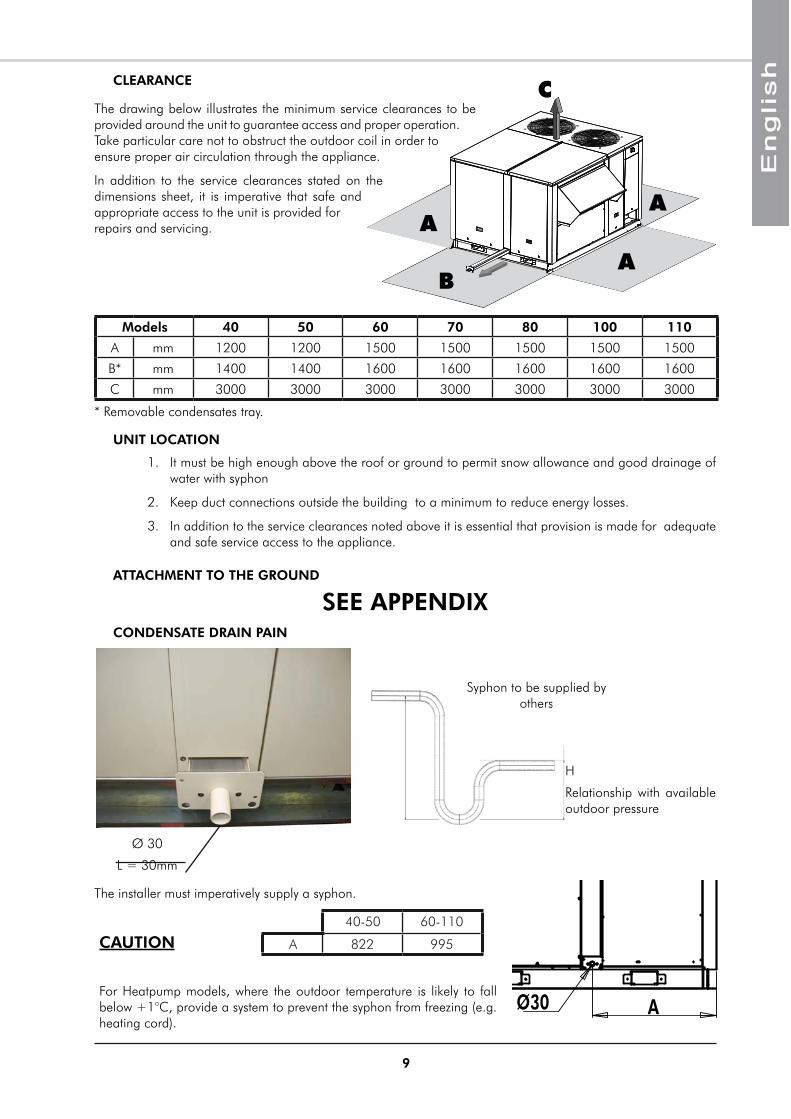
CLEARANCE
It must be high enough above the roof or ground to permit snow allowance and good drainage of 1. water with syphon
Keep duct connections outside the building to a minimum to reduce energy losses.2.
In addition to the service clearances noted above it is essential that provision is made for adequate 3. and safe service access to the appliance.
UNIT LOCATION
B
A
A
A
CThe drawing below illustrates the minimum service clearances to be provided around the unit to guarantee access and proper operation. Take particular care not to obstruct the outdoor coil in order to ensure proper air circulation through the appliance.
In addition to the service clearances stated on the dimensions sheet, it is imperative that safe and appropriate access to the unit is provided for repairs and servicing.
* Removable condensates tray.
ATTACHMENT TO THE GROUND
Models 40 50 60 70 80 100 110
A mm 1200 1200 1500 1500 1500 1500 1500
B* mm 1400 1400 1600 1600 1600 1600 1600
C mm 3000 3000 3000 3000 3000 3000 3000
SEE APPENDIX
CAUTION
For Heatpump models, where the outdoor temperature is likely to fall below +1°C, provide a system to prevent the syphon from freezing (e.g. heating cord).
CONDENSATE DRAIN PAIN
Ø 30
L = 30mm
The installer must imperatively supply a syphon.
Ø30 A
Syphon to be supplied by others
Syphon to be suppothers
H
Relationship with available outdoor pressure
40-50 60-110
A 822 995
10
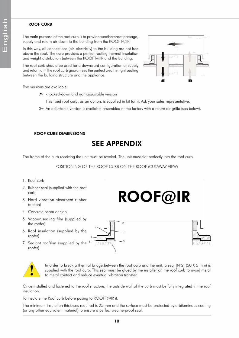
The frame of the curb receiving the unit must be reveled. The unit must slot perfectly into the roof curb.
POSITIONING OF THE ROOF CURB ON THE ROOF (CUTAWAY VIEW)
Roof curb1.
Rubber seal (supplied with the roof 2. curb)
Hard vibration-absorbent rubber 3. (option)
Concrete beam or slab4.
Vapour sealing film (supplied by 5. the roofer)
Roof insulation (supplied by the 6. roofer)
Sealant roofskin (supplied by the 7. roofer)
In order to break a thermal bridge between the roof curb and the unit, a seal (N°2) (50 X 5 mm) is supplied with the roof curb. This seal must be glued by the installer on the roof curb to avoid metal to metal contact and reduce eventual vibration transfer.
Once installed and fastened to the roof structure, the outside wall of the curb must be fully integrated in the roof insulation.
To insulate the Roof curb before posing to ROOFT@IR it.
The minimum insulation thickness required is 25 mm and the surface must be protected by a bituminous coating (or any other equivalent material) to ensure a perfect weatherproof seal.
ROOF@IR
1
2
3
4
5
6
7
ROOF CURB
The main purpose of the roof curb is to provide weatherproof passage, supply and return air down to the building from the ROOFT@IR.
In this way, all connections (air, electricity) to the building are not free above the roof. The curb provides a perfect roofing thermal insulation and weight distribution between the ROOFT@IR and the building.
The roof curb should be used for a downward configuration at supply and return air. The roof curb guarantees the perfect weathertight sealing between the building structure and the appliance.
Two versions are available:
knocked-down and non-adjustable version �
This fixed roof curb, as an option, is supplied in kit form. Ask your sales representative.
An adjustable version is available assembled at the factory with a return air grille (see below). �
SEE APPENDIX
ROOF CURB DIMENSIONS
11
The unit is designed to be connected to a duct work. Should it not be the case, a discharge protection grille and a device creating sufficient pressure drop must be supplied by the installer to avoid excess current draw generated at the motor (see blower curves in the appendix)
4 discharges and 4 intakes air configurations are available.
For each configuration, note the dimensions of the discharge air duct to be provided before the unit arrives on site. Make sure that it is fireproof and that it does produce toxic smoke in the event of a fire in the building. The interior surfaces must be smooth and cleanable to avoid contamination of the circulated air.
CONFIGURATION OF THE UNITGENERALITES
NEVER DRILL ANY HOLES IN THE AIR TREATMENT ZONE OF THE UNIT. THE MANUFACTURER’S WARRANTY WILL BE CANCELLED IN THE EVENT OF ANY WATER LEAKS RESULTING FROM THE DRILLING OF HOLES IN THE CASING.
Downward discharge: S1 �
Sideway discharge: S2 �
Front discharge: S3 �
Top discharge: S4 �
SUPPLY AIR
The "Downward discharge" and "Return air from below" versions requires the presence of a roof curb. For all cases, the installation must be analysed to avoid any risk of damage to the support on which the unit will be mounted, given its weight, .
DIMENSIONS
SEE APPENDIX
Return air from below: R1 �
Return air from the side: R2 �
Return air from the rear: R3 �
Return air from the top: R4 �
AIR INTAKE
12
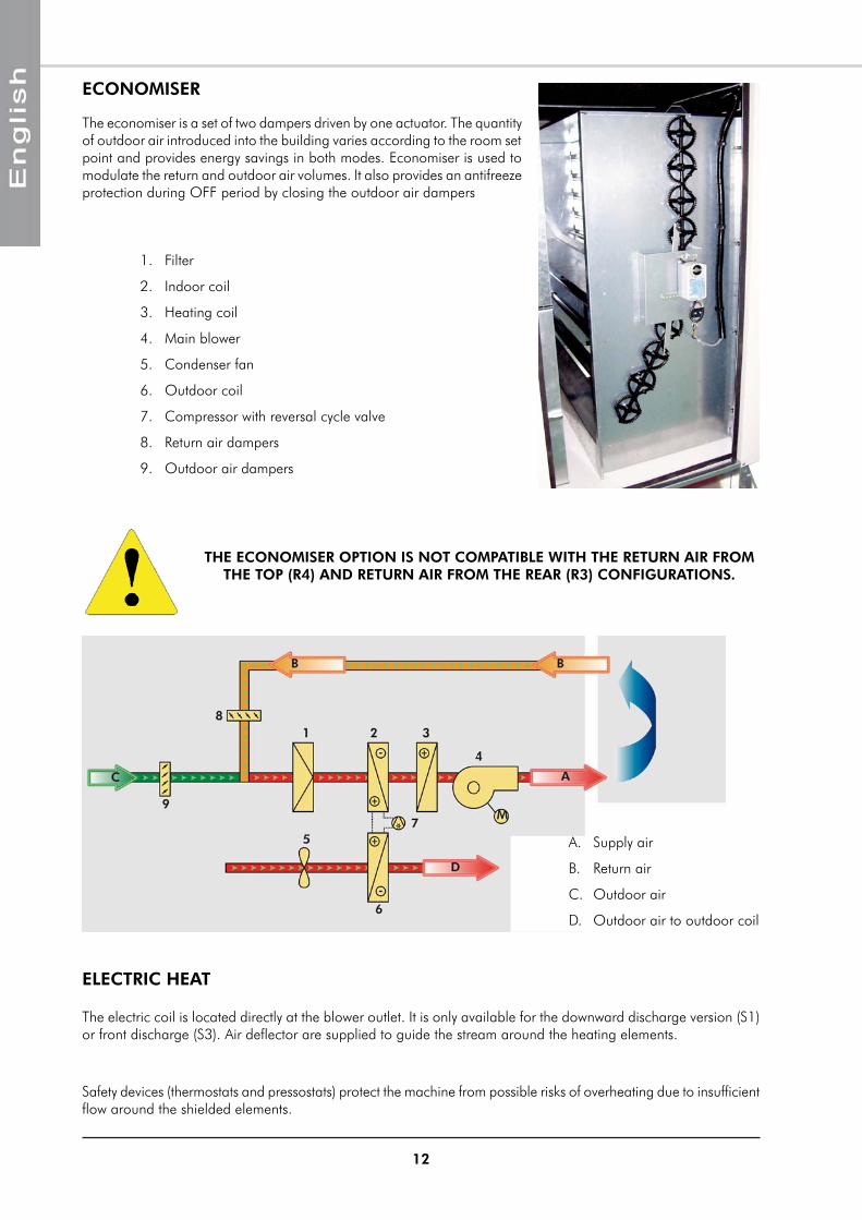
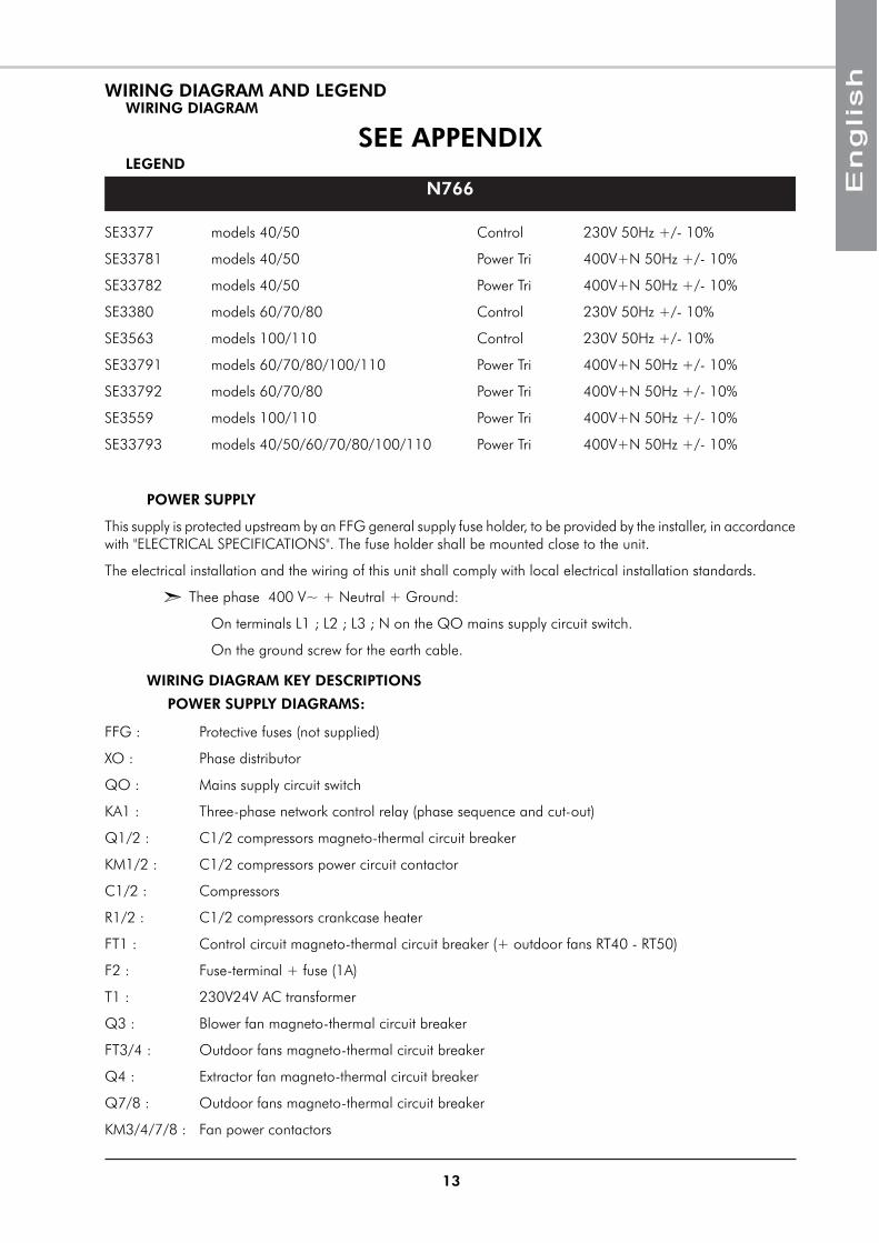
ECONOMISER
The economiser is a set of two dampers driven by one actuator. The quantity of outdoor air introduced into the building varies according to the room set point and provides energy savings in both modes. Economiser is used to modulate the return and outdoor air volumes. It also provides an antifreeze protection during OFF period by closing the outdoor air dampers
Filter1.
Indoor coil2.
Heating coil3.
Main blower4.
Condenser fan5.
Outdoor coil6.
Compressor with reversal cycle valve7.
Return air dampers8.
Outdoor air dampers9.
ELECTRIC HEAT
The electric coil is located directly at the blower outlet. It is only available for the downward discharge version (S1) or front discharge (S3). Air deflector are supplied to guide the stream around the heating elements.
Safety devices (thermostats and pressostats) protect the machine from possible risks of overheating due to insufficient flow around the shielded elements.
Supply airA.
Return airB.
Outdoor air C.
Outdoor air to outdoor coilD.
THE ECONOMISER OPTION IS NOT COMPATIBLE WITH THE RETURN AIR FROM THE TOP (R4) AND RETURN AIR FROM THE REAR (R3) CONFIGURATIONS.
13
LEGEND
N766
WIRING DIAGRAM
SEE APPENDIX
SE3377 models 40/50 Control 230V 50Hz +/- 10%
SE33781 models 40/50 Power Tri 400V+N 50Hz +/- 10%
SE33782 models 40/50 Power Tri 400V+N 50Hz +/- 10%
SE3380 models 60/70/80 Control 230V 50Hz +/- 10%
SE3563 models 100/110 Control 230V 50Hz +/- 10%
SE33791 models 60/70/80/100/110 Power Tri 400V+N 50Hz +/- 10%
SE33792 models 60/70/80 Power Tri 400V+N 50Hz +/- 10%
SE3559 models 100/110 Power Tri 400V+N 50Hz +/- 10%
SE33793 models 40/50/60/70/80/100/110 Power Tri 400V+N 50Hz +/- 10%
POWER SUPPLY
This supply is protected upstream by an FFG general supply fuse holder, to be provided by the installer, in accordance with "ELECTRICAL SPECIFICATIONS". The fuse holder shall be mounted close to the unit.
The electrical installation and the wiring of this unit shall comply with local electrical installation standards.
Thee phase 400 V~ + Neutral + Ground: �
On terminals L1 ; L2 ; L3 ; N on the QO mains supply circuit switch.
On the ground screw for the earth cable.
WIRING DIAGRAM KEY DESCRIPTIONS
POWER SUPPLY DIAGRAMS:
FFG : Protective fuses (not supplied)
XO : Phase distributor
QO : Mains supply circuit switch
KA1 : Three-phase network control relay (phase sequence and cut-out)
Q1/2 : C1/2 compressors magneto-thermal circuit breaker
KM1/2 : C1/2 compressors power circuit contactor
C1/2 : Compressors
R1/2 : C1/2 compressors crankcase heater
FT1 : Control circuit magneto-thermal circuit breaker (+ outdoor fans RT40 - RT50)
F2 : Fuse-terminal + fuse (1A)
T1 : 230V24V AC transformer
Q3 : Blower fan magneto-thermal circuit breaker
FT3/4 : Outdoor fans magneto-thermal circuit breaker
Q4 : Extractor fan magneto-thermal circuit breaker
Q7/8 : Outdoor fans magneto-thermal circuit breaker
KM3/4/7/8 : Fan power contactors
WIRING DIAGRAM AND LEGEND
14
AS : Soft start motor – three phase model (option)
M3 : Indoor fan motor
M4 : Extractor fan motor
CV : Extractor fan motor condenser
MV1/2/3/4 : Outdoor fan motor
CV1/2/3/4 : Outdoor fan motor condenser
Q5/6 : Heating elements magnetic circuit breakers (option)
K5/6 : Heating elements power contactors (option)
CH.1 : Small capacity heating option
CH.2 : Large capacity hearting option
SP7/8 : Condensing pressure sensor (All Seasons option)
FSP7/8 : Variable speed regulator (All Seasons option)
KA2/3 : Outdoor fans auxiliary contactors (All Seasons / Heat pump mode option)
HPD7/8 : Defrosting pressostat
CONTROL AND REGULATION DIAGRAMS
pCO1 : CAREL regulation
Q1/2 : C1/2 compressors additional magneto-thermal circuit breaker
Q3 : Blower fan additional magneto-thermal circuit breaker
Q5/6 : Heating elements additional magnetic circuit breaker (option)
Q7/8 : Outdoor fans additional magneto-thermal circuit breaker
OF1/2/3/4 : MO1/2/3/4 motors internal protection
FM : Heating safety thermostat (83°C) (option)
KA1 : Three-phase network control relay (phase sequence and cut-out) contact
HP1/2 : Circuits 1 and 2 automatic reset high-pressure pressostats
LP1/2 : Circuits 1 and 2 automatic reset low-pressure pressostats
OCT1/2 : Circuits 1 and 2 condenser temperature sensor
RAT : Intake air temperature sensor
OAT : Outdoor air temperature sensor (option)
SAT : Blown air temperature sensor (option)
RAH : Intake air hygrometry sensor (option)
IAQ : Intake air quality sensor (option)
OAH : Outdoor air hygrometry sensor (option)
SD : Smoke detector (option)
ECM : Economiser dampers motor (option)
HWV : Hot water coil modulating valve (option)
HWC : Anti-freezing, hot water battery warning
DFA : Clogged filter warning (ΔP>250Pa)
AF : Air pressostat (ΔP<50Pa)
ON/OFF : ON/OFF switch (not supplied)
15
PRESSOSTATS SETTING
Refrigerant circuit
Factory low pressure adjustment 2bars (29PSI)
Factory high pressure adjustment 42bars (609.16PSI)
Clogged filter ΔP warning (upstream/downstream filters) > 250 Pa
Airflow detector ΔP warning (upstream/downstream blower)< 50 Pa
RANGE AND SETTINGS OF THEMAL PROTECTION / NOMINAL INTENSITY OF THE CONTACTORS (CLASSE AC3)
COMPRESSORS CRANKCASE HEATER
Models 40 50 60 70 80 100 110
Power W 70 90 90 90 75 90+75 75
Model40 50 60 70 80 100 110
PE GE PE GE PE GE PE GE PE GE PE GE PE GE
Q1 Range 13-18A 17-23A 17-23A 24-32A 25-40A 25-40A 25-40A
Adjustment 15A 18A 21A 23A 35A 35A 38A
Q2 Range 13-18A 17-23A 17-23A 24-32A 25-40A 25-40A 25-40A
Adjustment 15A 18A 21A 23A 35A 38A 38A
Q3 Range 4-6.3A 9-14A 4-6.3A 9-14A 9-14A 13-18A 9-14A 13-18A 13-18A 13-18A 13-18A 13-18A 13-18A 13-18A
Adjustment 4A 10.9A 4.8A 11A 11A 14.8A 11A 14.8A 14.8A 15.6A 15.5A 16.3A 15.5A 16.3A
Q4 6A 6A 6A 6A 6A 6A 6A
Q7/8 Range / / / / / 2.5-4A 2.5-4A
Adjustment / / / / / 2.5A 2.5A
FT1 10A 10A 2A 2A 2A 2A 2A
FT3 / / 10A 10A 10A / /
FT4 / / 10A 10A 10A / /
Contactor AC3
KM1 18A 18A 25A 25A 40A 40A 40AKM2 18A 18A 25A 25A 40A 40A 40AKM3 9A 12A 9A 12A 12A 18A 12A 18A 18A 18A 18AKM4 9A 9A 9A 9A 9A 9A 9AKM7 9A 9A 9A 9A 9A 6A 6AKM8 / / 9A 9A 9A 6A 6A
SWS : Winter/Summer switch (not supplied)
KM1/2 : C1/2 compressors power contactor
KM3/4/7/8 : Fan power contactors
K5/6 : Heating elements power contactors (option)
EV1/2 : Circuits 1 and 2 cycle inversion valve (option)
KA2/3 : Relay contactors of the outdoor fan (option "all seasons"/ heat pump mode)
16
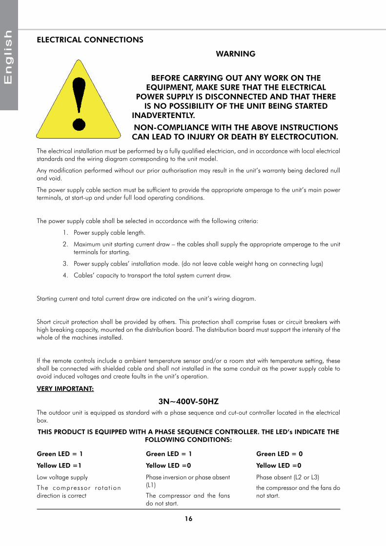
ELECTRICAL CONNECTIONS
WARNING
BEFORE CARRYING OUT ANY WORK ON THE EQUIPMENT, MAKE SURE THAT THE ELECTRICAL
POWER SUPPLY IS DISCONNECTED AND THAT THERE IS NO POSSIBILITY OF THE UNIT BEING STARTED
INADVERTENTLY.
NON-COMPLIANCE WITH THE ABOVE INSTRUCTIONS CAN LEAD TO INJURY OR DEATH BY ELECTROCUTION.
The electrical installation must be performed by a fully qualified electrician, and in accordance with local electrical standards and the wiring diagram corresponding to the unit model.
Any modification performed without our prior authorisation may result in the unit’s warranty being declared null and void.
The power supply cable section must be sufficient to provide the appropriate amperage to the unit’s main power terminals, at start-up and under full load operating conditions.
The power supply cable shall be selected in accordance with the following criteria:
Power supply cable length.1.
Maximum unit starting current draw – the cables shall supply the appropriate amperage to the unit 2. terminals for starting.
Power supply cables’ installation mode. (do not leave cable weight hang on connecting lugs)3.
Cables’ capacity to transport the total system current draw.4.
Starting current and total current draw are indicated on the unit’s wiring diagram.
Short circuit protection shall be provided by others. This protection shall comprise fuses or circuit breakers with high breaking capacity, mounted on the distribution board. The distribution board must support the intensity of the whole of the machines installed.
If the remote controls include a ambient temperature sensor and/or a room stat with temperature setting, these shall be connected with shielded cable and shall not installed in the same conduit as the power supply cable to avoid induced voltages and create faults in the unit’s operation.
VERY IMPORTANT:
3N~400V-50HZThe outdoor unit is equipped as standard with a phase sequence and cut-out controller located in the electrical box.
THIS PRODUCT IS EQUIPPED WITH A PHASE SEQUENCE CONTROLLER. THE LED’s INDICATE THE FOLLOWING CONDITIONS:
Green LED = 1
Yellow LED =1
Low voltage supply
The compressor ro ta t ion direction is correct
Green LED = 1
Yellow LED =0
Phase inversion or phase absent (L1)
The compressor and the fans do not start.
Green LED = 0
Yellow LED =0
Phase absent (L2 or L3)
the compressor and the fans do not start.
17
3N~400V
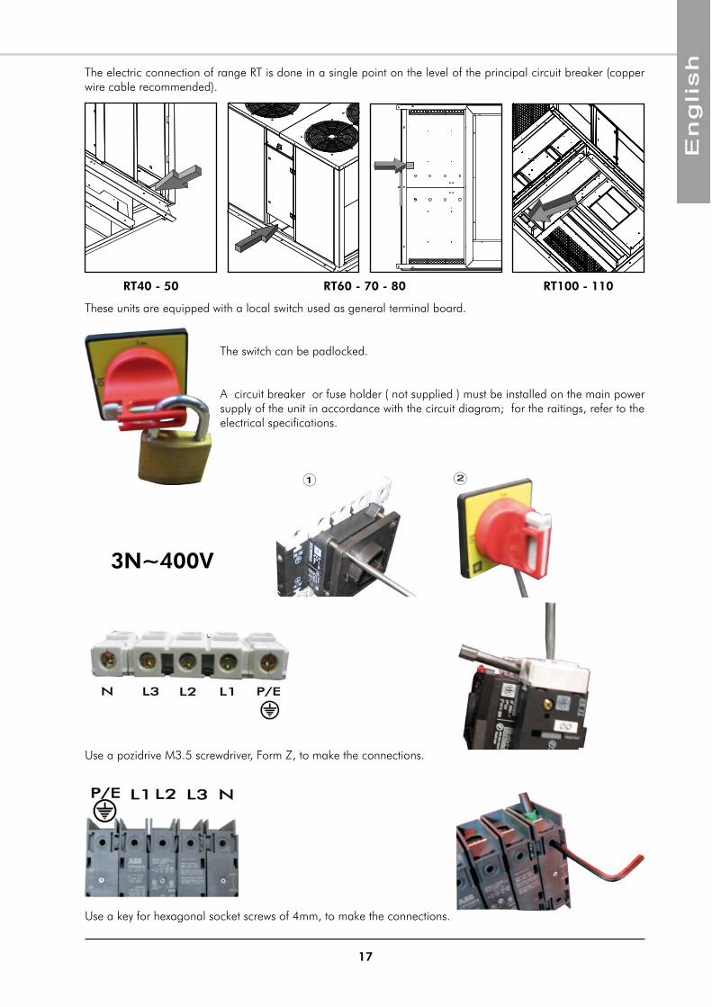
The electric connection of range RT is done in a single point on the level of the principal circuit breaker (copper wire cable recommended).
Use a key for hexagonal socket screws of 4mm, to make the connections.
Use a pozidrive M3.5 screwdriver, Form Z, to make the connections.
These units are equipped with a local switch used as general terminal board.
The switch can be padlocked.
A circuit breaker or fuse holder ( not supplied ) must be installed on the main power supply of the unit in accordance with the circuit diagram; for the raitings, refer to the electrical specifications.
RT40 - 50 RT60 - 70 - 80 RT100 - 110
18
COMMISSIONINGPRE-START CHECK LIST
ELECTRICAL CHECK
Electrical installation has been carried out according to unit wiring diagram and the Supply Authority 1. Regulations.
size fuses or circuit breaker has been installed at the main switchboard.2.
Supply voltages as specified on unit wiring diagram.3.
All cables are properly identified and tight connected at the unit.4.
the cables and wires are clear of or protected from pipework and sharp edges.5.
VISUAL CHECK
Clearances around unit including outdoor air entry and discharge openings and service accesses.1.
Unit mounted as specified.2.
For loose or missing bolts or screws.3.
For refrigerant leaks in connections and components.4.
DUCTING
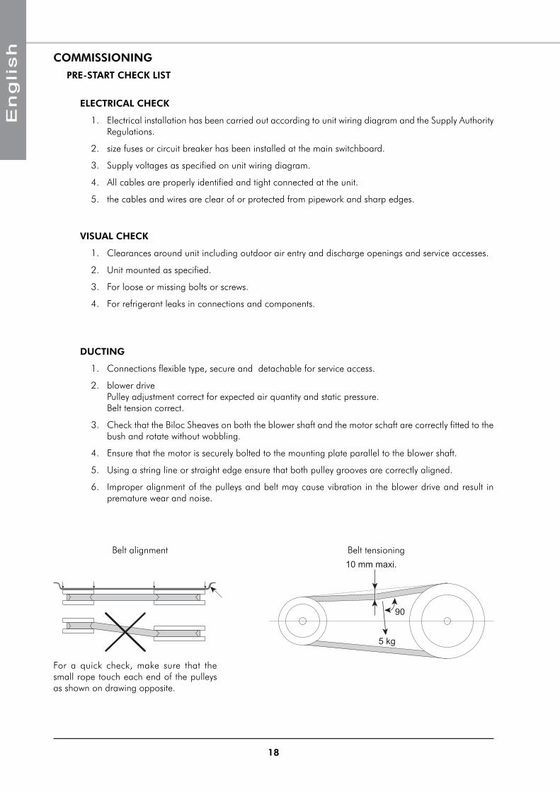
Connections flexible type, secure and detachable for service access.1.
blower drive 2. Pulley adjustment correct for expected air quantity and static pressure. Belt tension correct.
Check that the Biloc Sheaves on both the blower shaft and the motor schaft are correctly fitted to the 3. bush and rotate without wobbling.
Ensure that the motor is securely bolted to the mounting plate parallel to the blower shaft.4.
Using a string line or straight edge ensure that both pulley grooves are correctly aligned.5.
Improper alignment of the pulleys and belt may cause vibration in the blower drive and result in 6. premature wear and noise.
10 mm maxi.
5 kg
90
For a quick check, make sure that the small rope touch each end of the pulleys as shown on drawing opposite.
Belt alignment Belt tensioning
19
AIR BALANCING
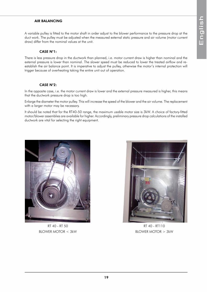
A variable pulley is fitted to the motor shaft in order adjust to the blower performance to the pressure drop at the duct work. The pulley must be adjusted when the measured external static pressure and air volume (motor current draw) differ from the nominal values at the unit.
CASE N°1:
There is less pressure drop in the ductwork than planned, i.e. motor current draw is higher than nominal and the external pressure is lower than nominal. The slower speed must be reduced to lower the treated airflow and re-establish the air balance point. It is imperative to adjust the pulley, otherwise the motor’s internal protection will trigger because of overheating taking the entire unit out of operation.
CASE N°2:
In the opposite case, i.e. the motor current draw is lower and the external pressure measured is higher, this means that the ductwork pressure drop is too high.
Enlarge the diameter the motor pulley. This will increase the speed of the blower and the air volume. The replacement with a larger motor may be necessary.
It should be noted that for the RT40-50 range, the maximum usable motor size is 3kW. A choice of factory-fitted motor/blower assemblies are available for higher. Accordingly, preliminary pressure drop calculations of the installed ductwork are vital for selecting the right equipment.
RT 40 - RT 50
BLOWER MOTOR < 3kW
RT 40 - RT110
BLOWER MOTOR > 3kW
20
OPERATING CHECK LIST
GENERAL
Cheek for any unusual noises or vibration in the running components, particularly at the main blower.
PHASE ROTATION PROTECTION
If the phase at the power supply are not correct, the phase rotation protection device will prevent the machine from starting.
ELECTRICAL
SET POINTS
Set point of compressor current overload relay.1.
Set point of indoor blower motor current overload relay.2.
NOTE : The outdoor blower motor is equiped with an internal current overload safety device with automatic reset.
OPERATING VOLTAGE:
Recheck voltage at unit supply terminals.
CONTROL
Operate system and thermostat switches.1.
Check unit is wired for correct control of blower, cooling and heating modes.2.
Verify all sensor signal, using the controller display.3.
BLOWER & DRIVE
Check that the pulleys on both blower shaft and motor are correctly fastened to the bush and rotate 1. without wobbling.
Check the alignment of the pulleys.2.
Cheek externaly the rotation direction of the blower.3.
Static Pressure and Air volum in the supply and return air ducts.4.
The indoor air quantity must be within the application limits of the main blower (see performances 5. curves). The associated static pressure must be such that the motor is operating within its normal amper rating. With all panels in place measure current on each phase of the indoor blower motor using clip-on type ammeter. Compare the amperage to the nameplate full load current.
COMPRESSOR AND REFRIGERATION SYSTEM
If outdoor air temperature is below 0°C make sure that the compressor crankcase heater has been 1. on for at least one hour before starting compressor.
Running check: Start the compressor. Check for any unusual noise or vibration.2.
Operating Pressures: Operate the unit for at last 20 minutes and ensure that the refrigerant pressures 3. are stabilised, and cheek that they are within the normal operating ranges.
Operating Temperature: Check discharge, suction and liquid temperatures.4.
Discharge temperature on cooling cycle should normally not exceed 105°C.5.
Suction superheat should between 5°K and 12°K.6.
21
The user is responsible for ensuring that it is in a proper working condition and that technical installation as well as the regular maintenance operations are performed by properly trained technicians and in accordance with the instructions contained in this manual.
MAINTENANCE
REGULAR MAINTENANCE
These units have been designed to require only minimal servicing, thanks to the use of a maximum number of lubricated-for-life components. Nevertheless, certain regular servicing operations are necessary to guarantee optimal system operation.
Servicing must be performed by experienced and qualified personnel only.
WARNING : Isolate unit from main power supply before working on unit.
GENERAL INSPECTION
Carry out a visual inspection of the complete installation in service.
Check the general cleanness of the installation, and check if the condensate evacuations is not blocked, specialy on the indoor coil, before the cooling season.
Check the condition of the condesate tray by pulling it out of the casing.
FINAL TASKSPlace the plugs back on the valves and check that they are properly tightened.
If needed, fix the cables and the pipes on the wall with clamping collars.
Operate the air conditioner in the presence of the user and explain all functions.
Show him how to remove, clean and place back the filters.
IN CASE OF WARRANTY - MATERIAL RETURN PROCEDUREMaterial must not be returned without permission of our After Sales Department.
To return the material, contact your nearest sales office and ask for a "return voucher". The return voucher shall be sent with the returned material and shall contain all necessary information concerning the problem encountered.
The return of the part is not an order for replacement. Therefore, a purchase order must be entered through your nearest distributor or regional sales office. The order should include part name, part number, model number and serial number of the unit involved.
Following our personal inspection of the returned part, and if it is determined that the failure is due to faulty material or workmanship, and in warranty, credit will be issued on customer's purchase order. All parts shall be returned to our factory, transportation charges prepaid.
ORDERING SERVICE AND SPARE PARTS ORDERThe part number, the order confirmation and the unit serial number indicated on the name plate must be provided whenever service works or spare parts are ordered.
For any spare part order, indicate the date of unit installation and date of failure. Use the part number provided by our service spare parts, if it not available, provide full description of the part required.
FINAL CHECK
All panels and fan guards are in place and secured.1.
.Unit clean and free of remainder installation material.2.
22
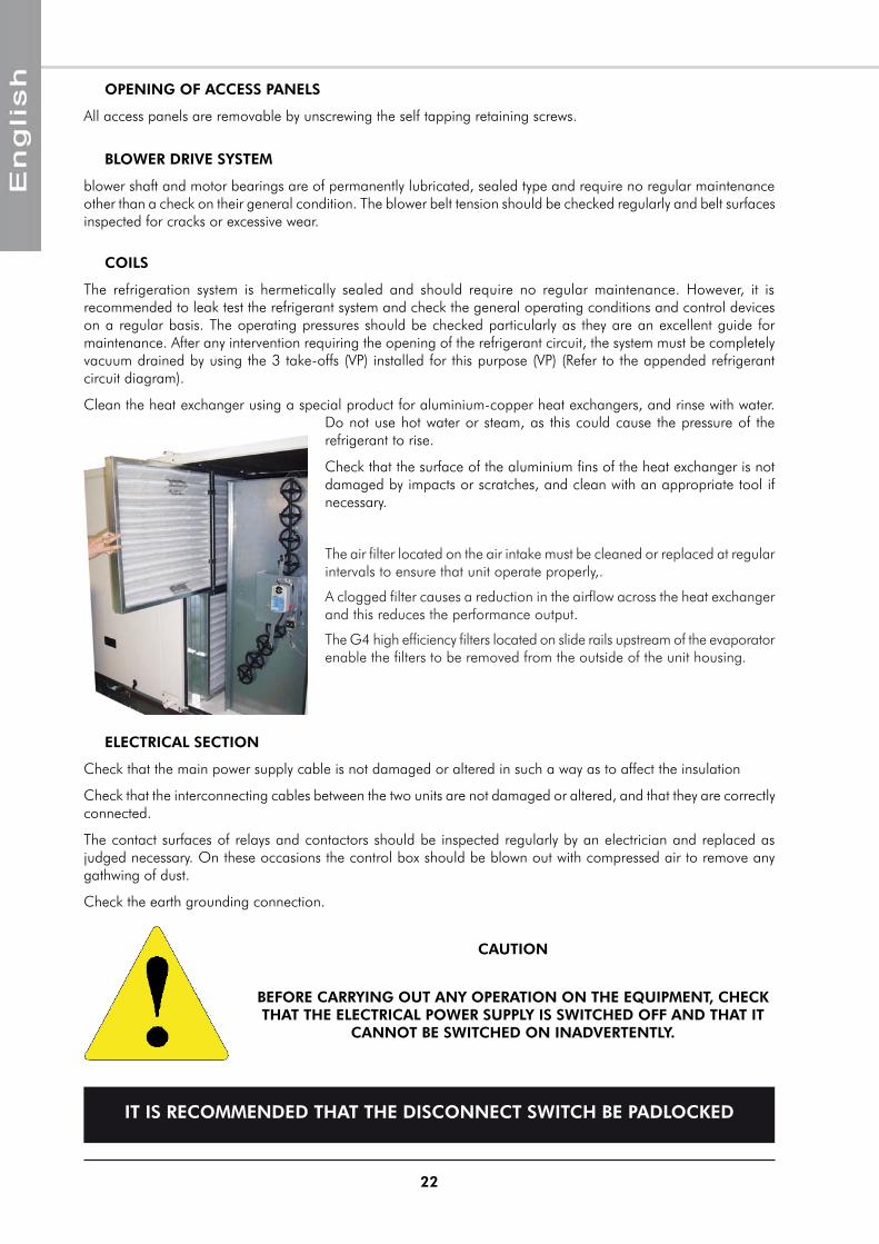
OPENING OF ACCESS PANELS
All access panels are removable by unscrewing the self tapping retaining screws.
COILS
The refrigeration system is hermetically sealed and should require no regular maintenance. However, it is recommended to leak test the refrigerant system and check the general operating conditions and control devices on a regular basis. The operating pressures should be checked particularly as they are an excellent guide for maintenance. After any intervention requiring the opening of the refrigerant circuit, the system must be completely vacuum drained by using the 3 take-offs (VP) installed for this purpose (VP) (Refer to the appended refrigerant circuit diagram).
Clean the heat exchanger using a special product for aluminium-copper heat exchangers, and rinse with water. Do not use hot water or steam, as this could cause the pressure of the refrigerant to rise.
Check that the surface of the aluminium fins of the heat exchanger is not damaged by impacts or scratches, and clean with an appropriate tool if necessary.
The air filter located on the air intake must be cleaned or replaced at regular intervals to ensure that unit operate properly,.
A clogged filter causes a reduction in the airflow across the heat exchanger and this reduces the performance output.
The G4 high efficiency filters located on slide rails upstream of the evaporator enable the filters to be removed from the outside of the unit housing.
IT IS RECOMMENDED THAT THE DISCONNECT SWITCH BE PADLOCKED
CAUTION
BEFORE CARRYING OUT ANY OPERATION ON THE EQUIPMENT, CHECK THAT THE ELECTRICAL POWER SUPPLY IS SWITCHED OFF AND THAT IT
CANNOT BE SWITCHED ON INADVERTENTLY.
ELECTRICAL SECTION
Check that the main power supply cable is not damaged or altered in such a way as to affect the insulation
Check that the interconnecting cables between the two units are not damaged or altered, and that they are correctly connected.
The contact surfaces of relays and contactors should be inspected regularly by an electrician and replaced as judged necessary. On these occasions the control box should be blown out with compressed air to remove any gathwing of dust.
Check the earth grounding connection.
BLOWER DRIVE SYSTEM
blower shaft and motor bearings are of permanently lubricated, sealed type and require no regular maintenance other than a check on their general condition. The blower belt tension should be checked regularly and belt surfaces inspected for cracks or excessive wear.
23
SERVICING CHECKLIST
CASING
Clean the outer panels.1.
Remove the panels.2.
Check that the insulation is not damaged. Repair as required.3.
CONDENSATE DRAIN PAN
Check that the drainage orifices, conduits and syphon are not blocked.1.
Eliminate all accumulated dirt.2.
Check that no traces of rust are present.3.
REFRIGERATION CIRCUIT
Check the presence of gas leaks.1.
Check that the copper tube or the capillary tube do not rub against any metal or vibrate.2.
Check that the compressors do not generate any abnormal noises or vibrations.3.
Check the compressor discharge temperature.4.
Check that that the crankcase heater is energised during the OFF cycle.5.
INDOOR COILS
Clean the fin surfaces as required.1.
Observe the condition of the blower and motors.2.
Clean or replace the filters.3.
OUTDOOR COIL
Check the cleanliness of the fin surfaces.1.
Check the condition of the fan and the fan motor.2.
PROTECTION DEVICES
Check the proper operation of the high pressure protection devices.1.
ELECTRICAL EQUIPMENT
Check nominal current draw and the condition of the fuses.1.
Check the tightness of the screw terminals.2.
Perform a visual check of the condition of the contacts.3.
Check the tightness of all cable connections.4.
Replace the panels and add any missing screws.5.
24
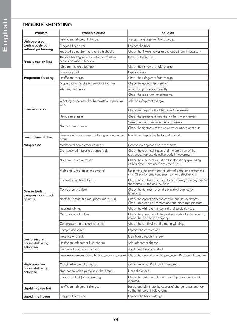
TROUBLE SHOOTING
Problem Probable cause Solution
Unit operates continuously but without performing
Insufficient refrigerant charge. Top up the refrigerant fluid charge.
Clogged filter dryer. Replace the filter.
Reduced output from one or both circuits Check the 4-ways valves and change them if necessary.
Frozen suction lineThe overheating setting on the thermostatic expansion valve is too low.
Increase the setting.
refrigerant charge too low Check the refrigerant fluid charge
Evaporator freezing
Filters clogged Replace filters
Insufficient charge Check the refrigerant fluid charge
Evaporator air intake temperature too low Check the economiser setting.
Excessive noise
Vibrating pipe work Attach the pipe work correctly.
Check the pipe work attachments.
Whistling noise from the thermostatic expansion valve
Add the refrigerant charge.
Check and replace the filter dryer if necessary.
Noisy compressor Check the pressure difference of the 4-ways valves.
No pressure increaseSeized bearings. Replace the compressor
Check the tightness of the compressor attachment nuts.
Low oil level in thePresence of one or several oil or gas leaks in the circuit
Locate and repair the leaks and add oil
compressor Mechanical compressor damage. Contact an approved Service Centre.
Crankcase oil heater resistance fault. Check the electrical circuit and the condition of the resistance. Replace defective parts if necessary.
One or both compressors do not operate.
No power at compressor Check the electrical circuit and seek out any grounding and/or short- -circuits. Check the fuses.
High pressure pressostat activated. Reset the pressostat from the control panel and restart the unit. Check for dirty condenser coil or defective fan
Control circuit fuse blown. Check the control circuit and look for any grounding and/or short-circuits. Replace the fuses.
Connection problem Check the tightness of all the electrical connection terminals.
Electrical circuits thermal protection cuts in. Check the operation of the control and safety devices. Check amperage of compressor and discharge pressure
Incorrect wiring. Check the wiring of the control and safety devices.
Mains voltage too low. Check the power line.If the problem is due to the network, inform the Electricity Company.
Compressor motor short–circuited. Check the continuity of the motor winding.
Compressor seized Replace the compressor.
Low pressure pressostat being activated.
Presence of a leak. Identify and repair the leak.
Insufficient refrigerant fluid charge. Add refrigerant charge.
Low air volume on evaporator check the blower and duct
High pressure pressostat being activated.
Incorrect operation of the high pressure pressostat. Check the operation of the pressostat. Replace it if required.
Outlet valve partially closed. Open the valve. Replace it if required.
Non-condensable particles in the circuit. Bleed the circuit
Condenser fan(s) not operating. Check the wiring and the motors. Repair and replace if required.
Liquid line too hotInsufficient refrigerant charge. Locate and eliminate the causes of charge losses and top
up the refrigerant fluid charge.
Liquid line frozen Clogged filter dryer. Replace the filter cartridge.
25
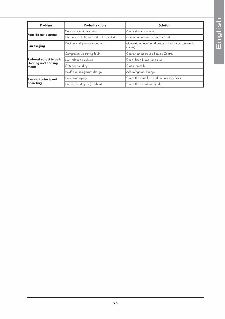
Problem Probable cause Solution
Fans do not operate.Electrical circuit problems. Check the connections.
Internal circuit thermal cut-out activated. Contact an approved Service Centre.
Fan surgingDuct network pressure too low. Generate an additional pressure loss (refer to aeraulic
curves)
Reduced output in both Heating and Cooling mode
Compressor operating fault Contact an approved Service Centre.
Low indoor air volume Check filter, blower and duct.
Outdoor coil dirty Clean the coil.
Insufficient refrigerant charge. Add refrigerant charge.
Electric heater is not operating.
No power supply. Check the main fuse and the auxiliary fuses.
Heater circuit open (overheat) Check the air volume or filter


APPENDIX / ANNEXE / ANLAGE / ALLEGATO / ANEXO
APPENDIXANNEXEANLAGE
ALLEGATOANEXO
APPENDIX / ANNEXE / ANLAGE / ALLEGATO / ANEXO
II
ANEXO
ALLEGATO
ANLAGE
ANNEXE
APPENDIXDIMENSIONS ........................................................................................... III
RT40 - RT50 .....................................................................................................................IIIRT60 - RT70 - RT80 ......................................................................................................... IVRT100 - RT110 ................................................................................................................. VEXHAUST BLOWER .......................................................................................................... VI
ATTACHMENT TO THE GROUND ............................................................. VIIRT40 - RT50 ................................................................................................................... VIIRT60 - RT70 - RT80 - RT100 - RT110 .............................................................................. VII
ROOF CURB........................................................................................... VIIIRT40 - RT50 .....................................................................................................................IXRT60 - RT70 - RT80 - RT100 - RT110 ................................................................................ XERP RT40 - RT50 ..............................................................................................................XIERP RT60 - RT70 - RT80 - RT100 - RT110 ........................................................................XIII
DUCT OUTLET DIMENSIONS ................................................................... XVS1 ..................................................................................................................................XVS2 ..................................................................................................................................XVS3 .................................................................................................................................XVIS4 .................................................................................................................................XVIR1 .................................................................................................................................XVIR2 .................................................................................................................................XVIR3 ............................................................................................................................... XVIII
DIMENSIONS ........................................................................................... IIIRT40 - RT50 .....................................................................................................................IIIRT60 - RT70 - RT80 ......................................................................................................... IVRT100 - RT110 ................................................................................................................. VEXHAUST BLOWER .......................................................................................................... VI
FIXATION AU SOL ................................................................................... VIIRT40 - RT50 ................................................................................................................... VIIRT60 - RT70 - RT80 - RT100 - RT110 .............................................................................. VII
COSTIERE .............................................................................................. VIIIRT40 - RT50 .....................................................................................................................IXRT60 - RT70 - RT80 - RT100 - RT110 ................................................................................ XERP RT40 - RT50 ..............................................................................................................XIERP RT60 - RT70 - RT80 - RT100 - RT110 ........................................................................XIII
DIMENSIONS DEPART DE GAINES............................................................ XVS1 ..................................................................................................................................XVS2 ..................................................................................................................................XVS3 .................................................................................................................................XVIS4 .................................................................................................................................XVIR1 .................................................................................................................................XVIR2 .................................................................................................................................XVIR3 ............................................................................................................................... XVIII
DIMENSIONI ............................................................................................ IIIRT40 - RT50 .....................................................................................................................IIIRT60 - RT70 - RT80 ......................................................................................................... IVRT100 - RT110 ................................................................................................................. VEXHAUST BLOWER .......................................................................................................... VI
FISSAGGIO AL SUOLO ............................................................................ VIIRT40 - RT50 ................................................................................................................... VII
RT60 - RT70 - RT80 - RT100 - RT110 .................................................................................. VIISCANALATURA PERIMETRALE .................................................................. VIII
RT40 - RT50 .....................................................................................................................IXRT60 - RT70 - RT80 - RT100 - RT110 ................................................................................ XERP RT40 - RT50 ..............................................................................................................XIERP RT60 - RT70 - RT80 - RT100 - RT110 ........................................................................XIII
DIMENSIONI TELLE USCITE DI CONDOTTA .............................................. XVS1 ..................................................................................................................................XVS2 ..................................................................................................................................XVS3 .................................................................................................................................XVIS4 .................................................................................................................................XVIR1 .................................................................................................................................XVIR2 .................................................................................................................................XVIR3 ............................................................................................................................... XVIII
DIMENSIONES ......................................................................................... IIIRT40 - RT50 .....................................................................................................................IIIRT60 - RT70 - RT80 ......................................................................................................... IVRT100 - RT110 ................................................................................................................. VEXHAUST BLOWER .......................................................................................................... VI
FIJACIÓN EN EL SUELO ........................................................................... VIIRT40 - RT50 ................................................................................................................... VIIRT60 - RT70 - RT80 - RT100 - RT110 .............................................................................. VII
PETO ...................................................................................................... VIIIRT40 - RT50 .....................................................................................................................IXRT60 - RT70 - RT80 - RT100 - RT110 ................................................................................ XERP RT40 - RT50 ..............................................................................................................XIERP RT60 - RT70 - RT80 - RT100 - RT110 ........................................................................XIII
DIMENSIONES DE LAS SALIDAS DE CONDUCTOS ................................... XVS1 ..................................................................................................................................XVS2 ..................................................................................................................................XVS3 .................................................................................................................................XVIS4 .................................................................................................................................XVIR1 .................................................................................................................................XVIR2 .................................................................................................................................XVIR3 ............................................................................................................................... XVIII
ABMESSUNGEN ....................................................................................... IIIRT40 - RT50 .....................................................................................................................IIIRT60 - RT70 - RT80 ......................................................................................................... IVRT100 - RT110 ................................................................................................................. VEXHAUST BLOWER .......................................................................................................... VI
BEFESTIGUNG AM BODEN ...................................................................... VIIRT40 - RT50 ................................................................................................................... VIIRT60 - RT70 - RT80 - RT100 - RT110 .............................................................................. VII
DACHRAHMEN ....................................................................................... VIIIRT40 - RT50 .....................................................................................................................IXRT60 - RT70 - RT80 - RT100 - RT110 ................................................................................ XERP RT40 - RT50 ..............................................................................................................XIERP RT60 - RT70 - RT80 - RT100 - RT110 ........................................................................XIII
ABMESSUNGEN DER KANALABGÄNGE .................................................... XVS1 ..................................................................................................................................XVS2 ..................................................................................................................................XVS3 .................................................................................................................................XVIS4 .................................................................................................................................XVIR1 .................................................................................................................................XVIR2 .................................................................................................................................XVIR3 ............................................................................................................................... XVIII
R4 ............................................................................................................................... XVIIIESQUEMA DEL CIRCUITO FRIGORIFÍCO ................................................. XIX
RTH40 - RTH50 ...............................................................................................................XXRTH60 - RTH70 - RTH80 - RTH100 - RTH110 ...................................................................XX
ESQUEMA ELECTRICO ............................................................................ XXIRT40 - RT50 .................................................................................................................. XXII
CONTROL .....................................................................................................................................XXIIPOWER ......................................................................................................................................... XXIII
RT60 - RT70 - RT80 .......................................................................................................XXVCONTROL .....................................................................................................................................XXV
RT100 - RT110 ............................................................................................................. XXVICONTROL ....................................................................................................................................XXVI
RT60 - RT70 - RT80 - RT100 - RT110 ........................................................................... XXVIIPOWER ........................................................................................................................................ XXVII
AJUSTE DEL ISTEMA AEROLICO .............................................................XXXIRT40 - RT50 ................................................................................................................. XXXI
AT15-15 ....................................................................................................................................... XXXI
RT60 - RT70 ................................................................................................................ XXXIIADH450 ...................................................................................................................................... XXXIIRDH450 ..................................................................................................................................... XXXIII
RT80 - RT100 - RT110 ................................................................................................ XXXIVADH500 ..................................................................................................................................... XXXIVRDH500 ...................................................................................................................................... XXXV
R4 ............................................................................................................................... XVIIISCHEMA DEL CIRCUITO REFRIGERANTE ................................................. XIX
RTH40 - RTH50 ...............................................................................................................XXRTH60 - RTH70 - RTH80 - RTH100 - RTH110 ...................................................................XX
SCHEMA ELETRICO ................................................................................ XXIRT40 - RT50 .................................................................................................................. XXII
CONTROL .....................................................................................................................................XXIIPOWER ......................................................................................................................................... XXIII
RT60 - RT70 - RT80 .......................................................................................................XXVCONTROL .....................................................................................................................................XXV
RT100 - RT110 ............................................................................................................. XXVICONTROL ....................................................................................................................................XXVI
RT60 - RT70 - RT80 - RT100 - RT110 ........................................................................... XXVIIPOWER ........................................................................................................................................ XXVII
REGOLAZIONE DEL SISTEMA DI TRATTAMENTO DELL'ARIA .....................XXXIRT40 - RT50 ................................................................................................................. XXXI
AT15-15 ....................................................................................................................................... XXXI
RT60 - RT70 ................................................................................................................ XXXIIADH450 ...................................................................................................................................... XXXIIRDH450 ..................................................................................................................................... XXXIII
RT80 - RT100 - RT110 ................................................................................................ XXXIVADH500 ..................................................................................................................................... XXXIVRDH500 ...................................................................................................................................... XXXV
R4 ............................................................................................................................... XVIIIKÄLTEKREISLAUFDIAGRAMM ................................................................... XIX
RTH40 - RTH50 ...............................................................................................................XXRTH60 - RTH70 - RTH80 - RTH100 - RTH110 ...................................................................XX
STROMLAUFPLANS ................................................................................. XXIRT40 - RT50 .................................................................................................................. XXII
CONTROL .....................................................................................................................................XXIIPOWER ......................................................................................................................................... XXIII
RT60 - RT70 - RT80 .......................................................................................................XXVCONTROL .....................................................................................................................................XXV
RT100 - RT110 ............................................................................................................. XXVICONTROL ....................................................................................................................................XXVI
RT60 - RT70 - RT80 - RT100 - RT110 ........................................................................... XXVIIPOWER ........................................................................................................................................ XXVII
REGELUNG DES LÜFTERSYSTEMS ...........................................................XXXIRT40 - RT50 ................................................................................................................. XXXI
AT15-15 ....................................................................................................................................... XXXI
RT60 - RT70 ................................................................................................................ XXXIIADH450 ...................................................................................................................................... XXXIIRDH450 ..................................................................................................................................... XXXIII
RT80 - RT100 - RT110 ................................................................................................ XXXIVADH500 ..................................................................................................................................... XXXIVRDH500 ...................................................................................................................................... XXXV
R4 ............................................................................................................................... XVIIIREFRIGERANT CIRCUIT DIAGRAM ........................................................... XIX
RTH40 - RTH50 ...............................................................................................................XXRTH60 - RTH70 - RTH80 - RTH100 - RTH110 ...................................................................XX
WIRING DIAGRAM .................................................................................. XXIRT40 - RT50 .................................................................................................................. XXII
CONTROL .....................................................................................................................................XXIIPOWER ......................................................................................................................................... XXIII
RT60 - RT70 - RT80 .......................................................................................................XXVCONTROL .....................................................................................................................................XXV
RT100 - RT110 ............................................................................................................. XXVICONTROL ....................................................................................................................................XXVI
RT60 - RT70 - RT80 - RT100 - RT110 ........................................................................... XXVIIPOWER ........................................................................................................................................ XXVII
AERAULIC ADJUSTMENT ........................................................................XXXIRT40 - RT50 ................................................................................................................. XXXI
AT15-15 ....................................................................................................................................... XXXI
RT60 - RT70 ................................................................................................................ XXXIIADH450 ...................................................................................................................................... XXXIIRDH450 ..................................................................................................................................... XXXIII
RT80 - RT100 - RT110 ................................................................................................ XXXIVADH500 ..................................................................................................................................... XXXIVRDH500 ...................................................................................................................................... XXXV
R4 ............................................................................................................................... XVIIISCHEMA DU CIRCUIT FRIGORIFIQUE ..................................................... XIX
RTH40 - RTH50 ...............................................................................................................XXRTH60 - RTH70 - RTH80 - RTH100 - RTH110 ...................................................................XX
SCHEMAS ELECTRIQUES ......................................................................... XXIRT40 - RT50 .................................................................................................................. XXII
CONTROL .....................................................................................................................................XXIIPOWER ......................................................................................................................................... XXIII
RT60 - RT70 - RT80 .......................................................................................................XXVCONTROL .....................................................................................................................................XXV
RT100 - RT110 ............................................................................................................. XXVICONTROL ....................................................................................................................................XXVI
RT60 - RT70 - RT80 - RT100 - RT110 ........................................................................... XXVIIPOWER ........................................................................................................................................ XXVII
CARACTERITIQUES AERAULIQUES .........................................................XXXIRT40 - RT50 ................................................................................................................. XXXI
AT15-15 ....................................................................................................................................... XXXI
RT60 - RT70 ................................................................................................................ XXXIIADH450 ...................................................................................................................................... XXXIIRDH450 ..................................................................................................................................... XXXIII
RT80 - RT100 - RT110 ................................................................................................ XXXIVADH500 ..................................................................................................................................... XXXIVRDH500 ...................................................................................................................................... XXXV
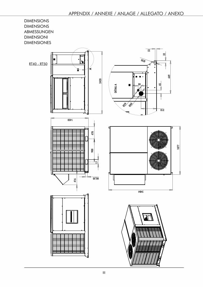
APPENDIX / ANNEXE / ANLAGE / ALLEGATO / ANEXO
III
DIMENSIONSDIMENSIONSABMESSUNGENDIMENSIONIDIMENSIONES
RT40 - RT50
900
478
416
1450
80,50
1877
2484
449
210
Ø60Ø29
45
32
22
Ø30
40
DÉTA
IL A
2420
A
APPENDIX / ANNEXE / ANLAGE / ALLEGATO / ANEXO
IV
RT60 - RT70 - RT80
3400
1747
1771.5 222732
77
Ø30
36
36
3328
80.5
651.
590
0
31.5
170
232
1266
.50
Ø75Ø
53
APPENDIX / ANNEXE / ANLAGE / ALLEGATO / ANEXO
V
RT100 - RT110
2308
3400
3326
1777
1813
3328
2200
900
651.
5017
0
APPENDIX / ANNEXE / ANLAGE / ALLEGATO / ANEXO
VI
532
A B
EXHAUST BLOWER
40-5
060
-70-
80
100-
110
A64
269
0
B82
891
0
APPENDIX / ANNEXE / ANLAGE / ALLEGATO / ANEXO
VII
1122 1122
1122 1122
55
120
30120
55
23
55 23
2484
1804
Ø12
39
142
122
1850
800
800
270
30
75
30
2140
190.50
736743.50743.50736
Ø14
190.50
10
20
3340
6030
60
3400
2200
ATTACHMENT TO THE GROUNDFIXATION AU SOLBEFESTIGUNG AM BODENFISSAGGIO AL SUOLOFIJACIÓN EN EL SUELO
RT40 - RT50
RT60 - RT70 - RT80 - RT100 - RT110
APPENDIX / ANNEXE / ANLAGE / ALLEGATO / ANEXO
VIII
G
H
F
E
96,50
96,5
0
400
A
102
B
C
D
A B C D E F G H
40-50 1726 1837 1956 2069 1182 610 608 536
60-70-80 100-110
2061 2172 2273 2384 1458 579 834 573
ROOF CURBCOSTIEREDACHRAHMENSCANALATURA PERIMETRALEPETO
ADJUSTABLE VERSION
VERSION REGLABLE
VERSTELLBARE AUSFÜHRUNG
VERSIONE REGOLABILE
VERSIÓN AJUSTABLE
RIGIDLY WELD PART 2 TO PART 1 TO ENSURE A RIGID SINGLE-PIECE ASSEMBLY.
SOUDER RIGIDEMENT LA PIÈCE 2 SUR 1 POUR FAIRE UN ENSEMBLE MONOBLOC.
DAS TEIL 2 AUF 1 STARR AUFSCHWEISSEN, UM EINE FESTE EINHEIT ZU BILDEN.
SALDARE RIGIDAMENTE IL PEZZO 2 SUL PEZZO 1 AL FINE DI OTTENERE UN INSIEME MONOBLOCCO.
SOLDAR RÍGIDAMENTE LA PIEZA 2 SOBRE LA PIEZA 1 PARA CONSTITUIR UN CONJUNTO MONOBLOQUE.
5°
1
2

APPENDIX / ANNEXE / ANLAGE / ALLEGATO / ANEXO
IX
AIR
FLO
WAI
R RE
TURN
445
178.
50
D
A
C13
0.50
397
B
260
==
RT40 - RT50
APPENDIX / ANNEXE / ANLAGE / ALLEGATO / ANEXO
X
AIR
SUPP
LY
AIR
RETU
RN
==
B
253
D10
31.5
019
0
AIR
RETU
RN
AIR
SUPP
LY
RT
100
RT
110
RT
60
RT
70
RT
80
RT60 - RT70 - RT80 - RT100 - RT110
APPENDIX / ANNEXE / ANLAGE / ALLEGATO / ANEXO
XI
ERP RT40 - RT50
SUPP
LY A
IR
SUPP
LY A
IRRE
TURN
AIR
80
512.5
1975
80
2078
364
364
153
207
1900
2135
RETU
RN A
IR
80
1740
80
1836
8080
527 int. 420 int.
48
48
72
550
COUP
E A-
A
SUPP
LY A
IR
RETU
RN A
IR
293.
5
841
INT.
COUP
E C-
C
SUPP
LY A
IR
80
10311
85 IN
T.
COUP
E D-
D
RETU
RN A
IR
11511
5
898
584
477
1242
230
230
180 180
28.5
18
28.5
18
230
230
180 180
Ø7
Ø7
VUE D
E DES
SOUS
A A
CC
DD
APPENDIX / ANNEXE / ANLAGE / ALLEGATO / ANEXO
XII
364
310
2135
39
23.5
023
.50
1900
SUPP
LY A
IR
RETU
RN A
IR
AIR
FLO
WAI
R RE
TURN
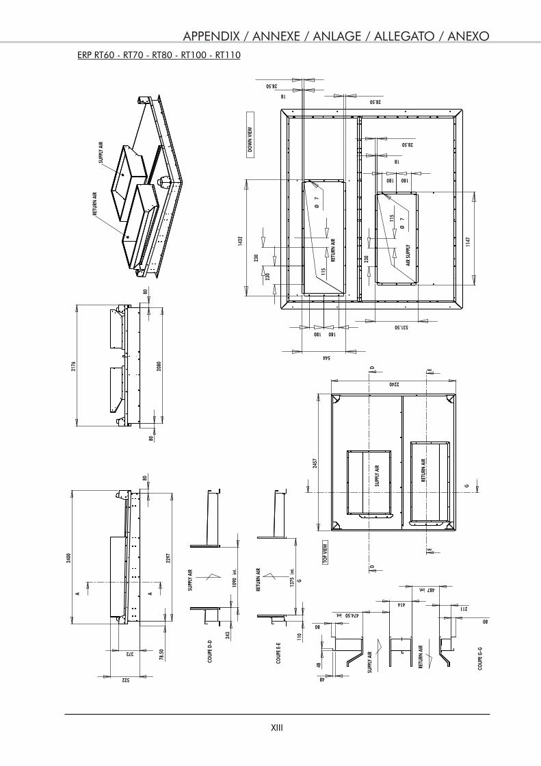
APPENDIX / ANNEXE / ANLAGE / ALLEGATO / ANEXO
XIII
ERP RT60 - RT70 - RT80 - RT100 - RT110
SUPP
LY A
IR
RETU
RN A
IR
372
78.5
0
522
80
2297
2400
2457
2240
TOP
VIEW
115
115
28.50
18
544
1432
531.50
1147
28.50
28.50
18
Ø7
180 180
230
230
180 180
230
Ø7
DOW
N V
IEW
AIR
SUPP
LY
RETU
RN A
IR
243
1090
int.
COUP
E D-
D 110
1375
int.
COUP
E E-
E
SUPP
LY A
IR
RETU
RN A
IR
SUPP
LY A
IRRE
TURN
AIR
80
211
487 int.
414
474.50 int.
80
48
48 COUP
E G
-G
SUPP
LY A
IR
RETU
RN A
IR
80
2080
80
2176
A A
DD
EE
G
G
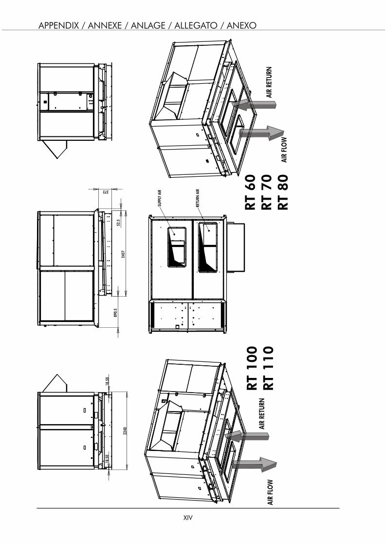
APPENDIX / ANNEXE / ANLAGE / ALLEGATO / ANEXO
XIV
372
2457
52.5
890.
5
2240
18.5
018
.50
SUPP
LY A
IR
RETU
RN A
IR
AIR
FLO
W
AIR
RETU
RNAI
R FL
OW
AIR
RETU
RNRT
100
RT
110
RT
60
RT
70
RT
80

APPENDIX / ANNEXE / ANLAGE / ALLEGATO / ANEXO
XV
S2
A
EB
C
D
F
51
F
F
S1
B
A
D
C
33
F F
F-F
DUCT OUTLET DIMENSIONSDIMENSIONS DEPART DE GAINESABMESSUNGEN DER KANALABGÄNGEDIMENSIONI TELLE USCITE DI CONDOTTADIMENSIONES DE LAS SALIDAS DE CONDUCTOS
40-50 60-70 80-100-110Electric heat
Electric heat
Electric heat
A 645.5 437 737 409 738 409B 295 249.5 325 324 328 324C 497 793 574 1030.5 641 1030.5D 430 413 574 574 641 574
40-50 60-70 80-100-110
A 593.5 658 660
B 365 391.5 414.5
C 601 734 803
D 534 734 803
E 65.5 73.5 73.5
DELIVERED NOT INSTALLEDLIVRE NON INSTALLEGELIEFERT NICHT INSTALLIERTCONSEGNATO NON INSTALLATOSUMINISTRADO NO INSTALADO
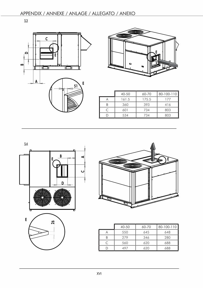
APPENDIX / ANNEXE / ANLAGE / ALLEGATO / ANEXO
XVI
S3
AB
D
C
EE
E
26
B
A
C
D E
51
E
E
40-50 60-70 80-100-110
A 161.5 175.5 177
B 360 393 416
C 601 734 803
D 534 734 803
40-50 60-70 80-100-110
A 550 645 648
B 279 346 280
C 560 620 688
D 497 620 688
S4
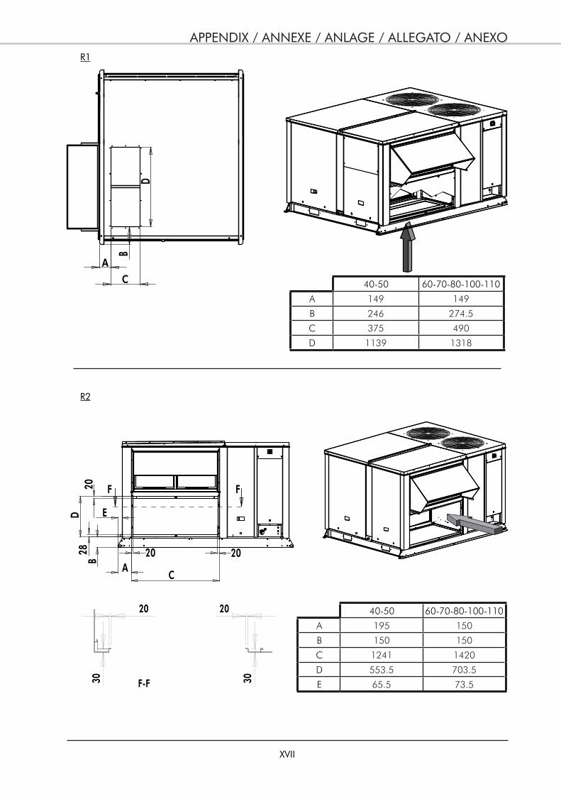
APPENDIX / ANNEXE / ANLAGE / ALLEGATO / ANEXO
XVII
R2
CA
ED
B20
28 20 20
30
20 20
30F-F
F F
R1
B
C
D
A
40-50 60-70-80-100-110
A 149 149
B 246 274.5
C 375 490
D 1139 1318
40-50 60-70-80-100-110
A 195 150
B 150 150
C 1241 1420
D 553.5 703.5
E 65.5 73.5
APPENDIX / ANNEXE / ANLAGE / ALLEGATO / ANEXO
XVIII
R4
R3
D
C
A
B
E
26
DC
BA
20 20
E E
E-E
2028
20
30
20
30
40-50 60-70-80-100-110
A 90 100
B 150 150
C 663 826
D 750 854
40-50 60-70-80-100-110
A 180 180
B 180 180
C 1139 1359
D 439 532
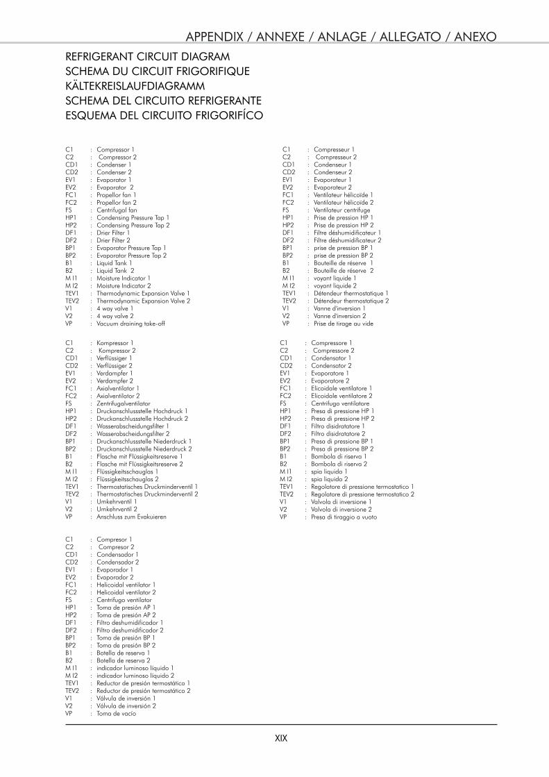
APPENDIX / ANNEXE / ANLAGE / ALLEGATO / ANEXO
XIX
REFRIGERANT CIRCUIT DIAGRAMSCHEMA DU CIRCUIT FRIGORIFIQUEKÄLTEKREISLAUFDIAGRAMMSCHEMA DEL CIRCUITO REFRIGERANTEESQUEMA DEL CIRCUITO FRIGORIFÍCO
C1 : Compressor 1C2 : Compressor 2CD1 : Condenser 1CD2 : Condenser 2EV1 : Evaporator 1EV2 : Evaporator 2FC1 : Propellor fan 1FC2 : Propellor fan 2FS : Centrifugal fanHP1 : Condensing Pressure Tap 1HP2 : Condensing Pressure Tap 2DF1 : Drier Filter 1DF2 : Drier Filter 2BP1 : Evaporator Pressure Tap 1BP2 : Evaporator Pressure Tap 2B1 : Liquid Tank 1B2 : Liquid Tank 2M I1 : Moisture Indicator 1M I2 : Moisture Indicator 2TEV1 : Thermodynamic Expansion Valve 1TEV2 : Thermodynamic Expansion Valve 2V1 : 4 way valve 1V2 : 4 way valve 2VP : Vacuum draining take-off
C1 : Compresseur 1C2 : Compresseur 2CD1 : Condenseur 1CD2 : Condenseur 2EV1 : Evaporateur 1EV2 : Evaporateur 2FC1 : Ventilateur hélicoïde 1FC2 : Ventilateur hélicoïde 2FS : Ventilateur centrifugeHP1 : Prise de pression HP 1HP2 : Prise de pression HP 2DF1 : Filtre déshumidificateur 1DF2 : Filtre déshumidificateur 2BP1 : prise de pression BP 1BP2 : prise de pression BP 2B1 : Bouteille de réserve 1B2 : Bouteille de réserve 2M I1 : voyant liquide 1M I2 : voyant liquide 2TEV1 : Détendeur thermostatique 1TEV2 : Détendeur thermostatique 2V1 : Vanne d'inversion 1V2 : Vanne d'inversion 2VP : Prise de tirage au vide
C1 : Kompressor 1C2 : Kompressor 2CD1 : Verflüssiger 1CD2 : Verflüssiger 2EV1 : Verdampfer 1EV2 : Verdampfer 2FC1 : Axialventilator 1FC2 : Axialventilator 2FS : ZentrifugalventilatorHP1 : Druckanschlussstelle Hochdruck 1HP2 : Druckanschlussstelle Hochdruck 2DF1 : Wasserabscheidungsfilter 1DF2 : Wasserabscheidungsfilter 2BP1 : Druckanschlussstelle Niederdruck 1BP2 : Druckanschlussstelle Niederdruck 2B1 : Flasche mit Flüssigkeitsreserve 1B2 : Flasche mit Flüssigkeitsreserve 2M I1 : Flüssigkeitsschauglas 1M I2 : Flüssigkeitsschauglas 2TEV1 : Thermostatisches Druckminderventil 1 TEV2 : Thermostatisches Druckminderventil 2V1 : Umkehrventil 1V2 : Umkehrventil 2VP : Anschluss zum Evakuieren
C1 : Compressore 1C2 : Compressore 2CD1 : Condensator 1CD2 : Condensator 2EV1 : Evaporatore 1EV2 : Evaporatore 2FC1 : Elicoidale ventilatore 1FC2 : Elicoidale ventilatore 2FS : Centrifugo ventilatoreHP1 : Presa di pressione HP 1HP2 : Presa di pressione HP 2DF1 : Filtro disidratatore 1DF2 : Filtro disidratatore 2BP1 : Presa di pressione BP 1BP2 : Presa di pressione BP 2B1 : Bombola di riserva 1B2 : Bombola di riserva 2M I1 : spia liquido 1M I2 : spia liquido 2TEV1 : Regolatore di pressione termostatico 1TEV2 : Regolatore di pressione termostatico 2V1 : Valvola di inversione 1V2 : Valvola di inversione 2VP : Presa di tiraggio a vuoto
C1 : Compresor 1C2 : Compresor 2CD1 : Condensador 1CD2 : Condensador 2EV1 : Evaporador 1EV2 : Evaporador 2FC1 : Helicoidal ventilator 1FC2 : Helicoidal ventilator 2FS : Centrifugo ventilatorHP1 : Toma de presión AP 1HP2 : Toma de presión AP 2DF1 : Filtro deshumidificador 1DF2 : Filtro deshumidificador 2BP1 : Toma de presión BP 1BP2 : Toma de presión BP 2B1 : Botella de reserva 1B2 : Botella de reserva 2M I1 : indicador luminoso líquido 1M I2 : indicador luminoso líquido 2TEV1 : Reductor de presión termostático 1TEV2 : Reductor de presión termostático 2V1 : Válvula de inversión 1V2 : Válvula de inversión 2VP : Toma de vacío
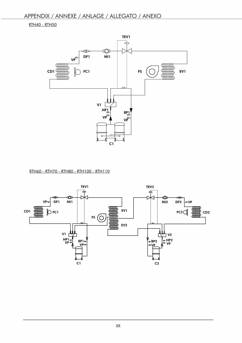
APPENDIX / ANNEXE / ANLAGE / ALLEGATO / ANEXO
XX
V1
TEV1
MI1DF1
FC1
FS
EV1CD1
HP1 BP1
C1
HP2
MI2
V2
CD2FC2
DF2
BP2
C2
TEV2
EV2
VP VP
VP VPVPVP
V1
TEV1
MI1DF1
FC1 FS EV1CD1
HP1BP1
C1
VPVP
VP
RTH40 - RTH50
RTH60 - RTH70 - RTH80 - RTH100 - RTH110
APPENDIX / ANNEXE / ANLAGE / ALLEGATO / ANEXO
XXI
WIRING DIAGRAMSCHEMAS ELECTRIQUESSTROMLAUFPLANSSCHEMA ELETRICOESQUEMA ELECTRICO
TAKE CARE!
These wiring diagrams are correct at the time of publication. Manufacturing changes can lead to modifications. Always refer to the diagram supplied with the product.
ATTENTION
Ces schémas sont corrects au moment de la publication. Les variantes en fabrication peuvent entraîner des modifications. Reportez-vous toujours au schéma livré avec le produit.
ACHTUNG!
Diese Stromlaufplans sind zum Zeitpunkt der Veröffentlichung gültig. In Herstellung befindliche Varianten können Änderungen mit sich bringen. In jedem Fall den mit dem Produkt gelieferten Stromlaufplan hinzuziehen.
ATTENZIONE !
Questi schemi sono corretti al momento della pubblicazione. Le varianti apportate nel corso della fabbricazione possono comportare modifiche. Far sempre riferimento allo schema fornito con il prodotto.
ATENCIÓN !
Esto esquemas son correctos en el momento de la publicación. Pero las variantes en la fabricación pueden ser motivo de modificaciones. Remítase siempre al esquema entregado con el producto.
PUESTA FUERA DE TNESIÓN OBLIGATORIA ANTES DE CUALQUIER INTERVENCIÓN EN LAS CAJAS ELÉCTRICAS!
PRIMA DI OGNI INTERVENTO SULLE CASSETTE ELETTRICHE ESCLUDERE TASSATIVAMENTE L’ALIMENTAZIONE !
VOR JEDEM EINGRIFF AN DEN ANSCHLUßKÄSTEN UNBEDINGT DAS GERÄT ABSCHALTEN!
MISE HORS TENSION OBLIGATOIRE AVANT TOUTE INTERVENTION DANS LES BOITIERS ELECTRIQUES.
POWER SUPPLY MUST BE SWITCHED OFF BEFORE STARTING TO WORK IN THE ELECTRIC CONTROL BOXES!
APPENDIX / ANNEXE / ANLAGE / ALLEGATO / ANEXO
XXII
RT40 - RT50
CONTROL
<
pC
O1
>
13 14
13 14
<
> >
>
>
>
APPENDIX / ANNEXE / ANLAGE / ALLEGATO / ANEXO
XXIII
POWER
ASL1
A1
A3
L2L3
T1T2
T3
APPENDIX / ANNEXE / ANLAGE / ALLEGATO / ANEXO
XXIV
APPENDIX / ANNEXE / ANLAGE / ALLEGATO / ANEXO
XXV
RT60 - RT70 - RT80
CONTROL
<
pC
O1
>
<
>>
<
> >
>
>
>>
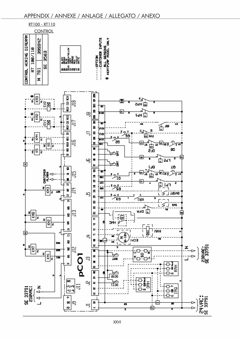
APPENDIX / ANNEXE / ANLAGE / ALLEGATO / ANEXO
XXVI
RT100 - RT110
CONTROL
<
pC
O1
>
<
>
<
>
>
>
>>
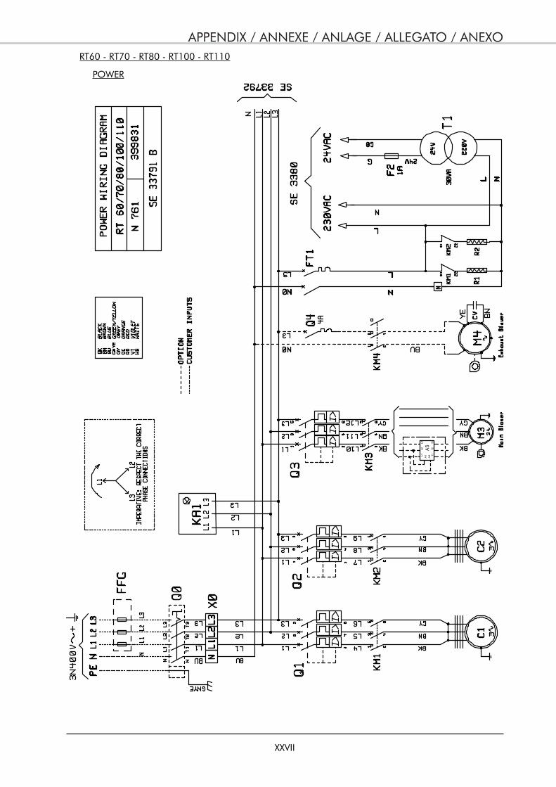
APPENDIX / ANNEXE / ANLAGE / ALLEGATO / ANEXO
XXVII
POWER
ASL1
A1
A3
L2L3
T1T2
T3
RT60 - RT70 - RT80 - RT100 - RT110
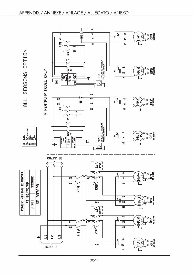
APPENDIX / ANNEXE / ANLAGE / ALLEGATO / ANEXO
XXVIII
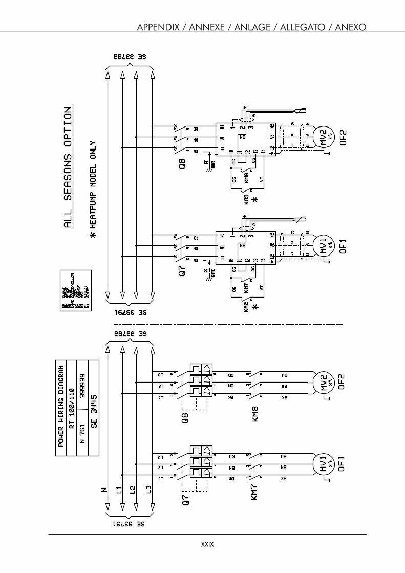
APPENDIX / ANNEXE / ANLAGE / ALLEGATO / ANEXO
XXIX
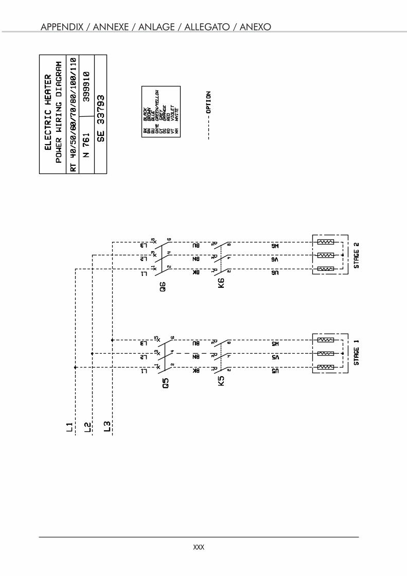
APPENDIX / ANNEXE / ANLAGE / ALLEGATO / ANEXO
XXX
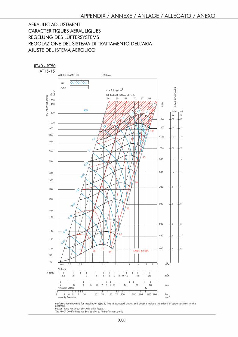
APPENDIX / ANNEXE / ANLAGE / ALLEGATO / ANEXO
XXXI
AERAULIC ADJUSTMENTCARACTERITIQUES AERAULIQUESREGELUNG DES LÜFTERSYSTEMSREGOLAZIONE DEL SISTEMA DI TRATTAMENTO DELL'ARIAAJUSTE DEL ISTEMA AEROLICO
RT40 - RT50
400
450
500
600
700
800
900
1000
1100
1200
1300
5
5
6
7
8
10
11
12
13
14
16
S-SC
W
6
7
8
9
11
12
14
15
17
18
20
AR
W
.090
.021
.081
.052
.073
.055
.057
.1 1
.1 5
.2 23
4
.5 5.7 5 11
54 60 67 70 67 58
47
6570
75
80
85
90
95
100
0.4 0.5 0.7 1 1.4 2 3 4 5 6 780
90
100
120
140
180
200
250
300
350
400
500
600
700
800
900
1000
1200
14001500
SE
RP L
ATOT
ER
US
WHEEL DIAMETER 393 mm
AR
S-SC
1.5 2 3 4 5 6 7 8 9 10 14 20X 1000
Volume
2 3 4 5 6 7 8 9 10 14 20 30Air outlet veloci ty
2 3 4 5 7 10 20 30 50 70 100 200 300 500 700Velocity Pressure
KW
m /s
MP
R
aP
m/N IMPELLER TOTAL EFF. %
m /h
m/s
PaN/m
LW(A) in dB(A)
= 1.2 Kg / m
RE
WO
P G
NIRAE
B
32
3
3
2
AT15-15
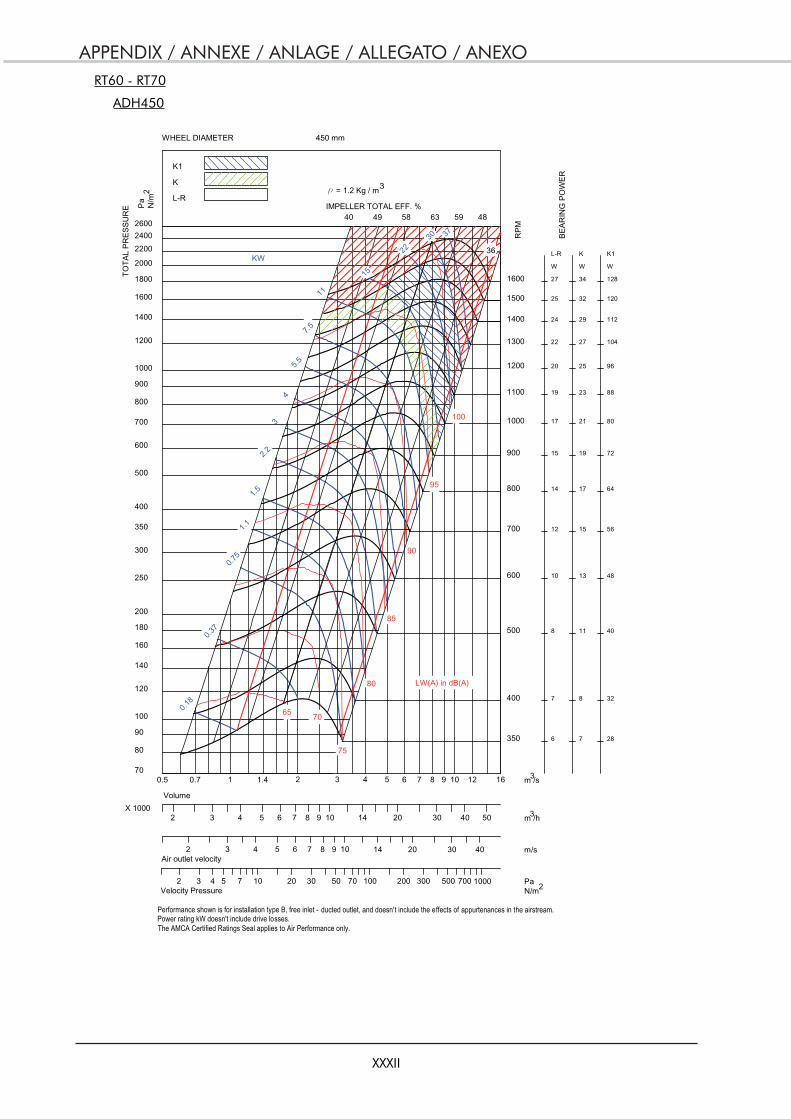
APPENDIX / ANNEXE / ANLAGE / ALLEGATO / ANEXO
XXXII
RT60 - RT70
ADH450
Performance shown is for installation type B, free inlet - ducted outlet, and doesn't include the effects of appurtenances in the airstream.Power rating kW doesn't include drive losses.The AMCA Certified Ratings Seal applies to Air Performance only.
r
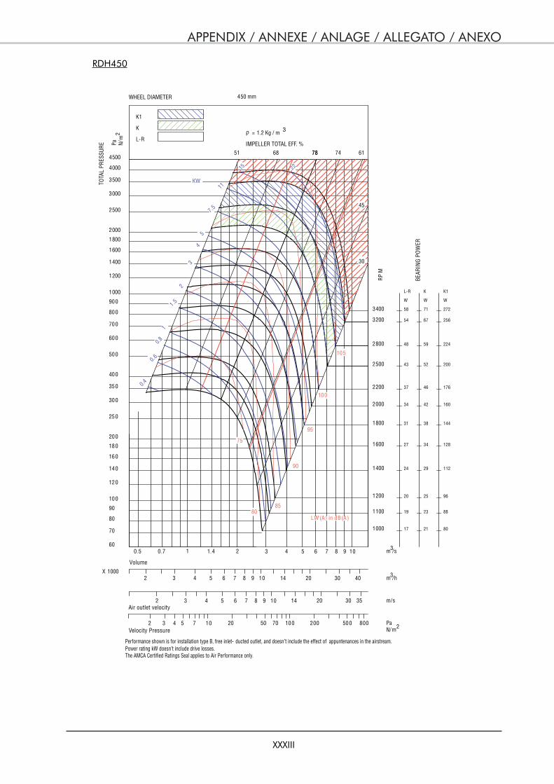
APPENDIX / ANNEXE / ANLAGE / ALLEGATO / ANEXO
XXXIII
RDH450
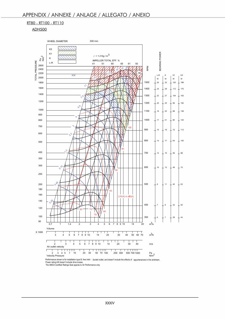
APPENDIX / ANNEXE / ANLAGE / ALLEGATO / ANEXO
XXXIV
RT80 - RT100 - RT110
ADH500
Performance shown is for installation type B, free inlet - ducted outlet, and doesn't include the effects of appurtenances in the airstream.Power rating kW doesn't include drive losses.The AMCA Certified Ratings Seal appl ies to Air Performance only.
r
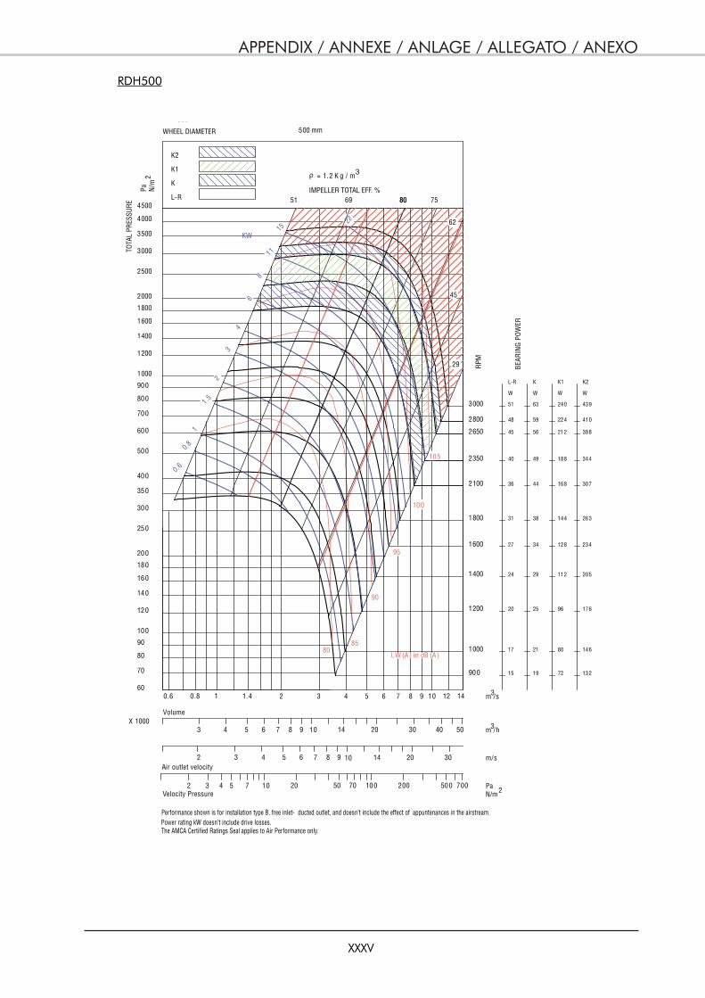
APPENDIX / ANNEXE / ANLAGE / ALLEGATO / ANEXO
XXXV
RDH500

APPENDIX / ANNEXE / ANLAGE / ALLEGATO / ANEXO
XXXVI
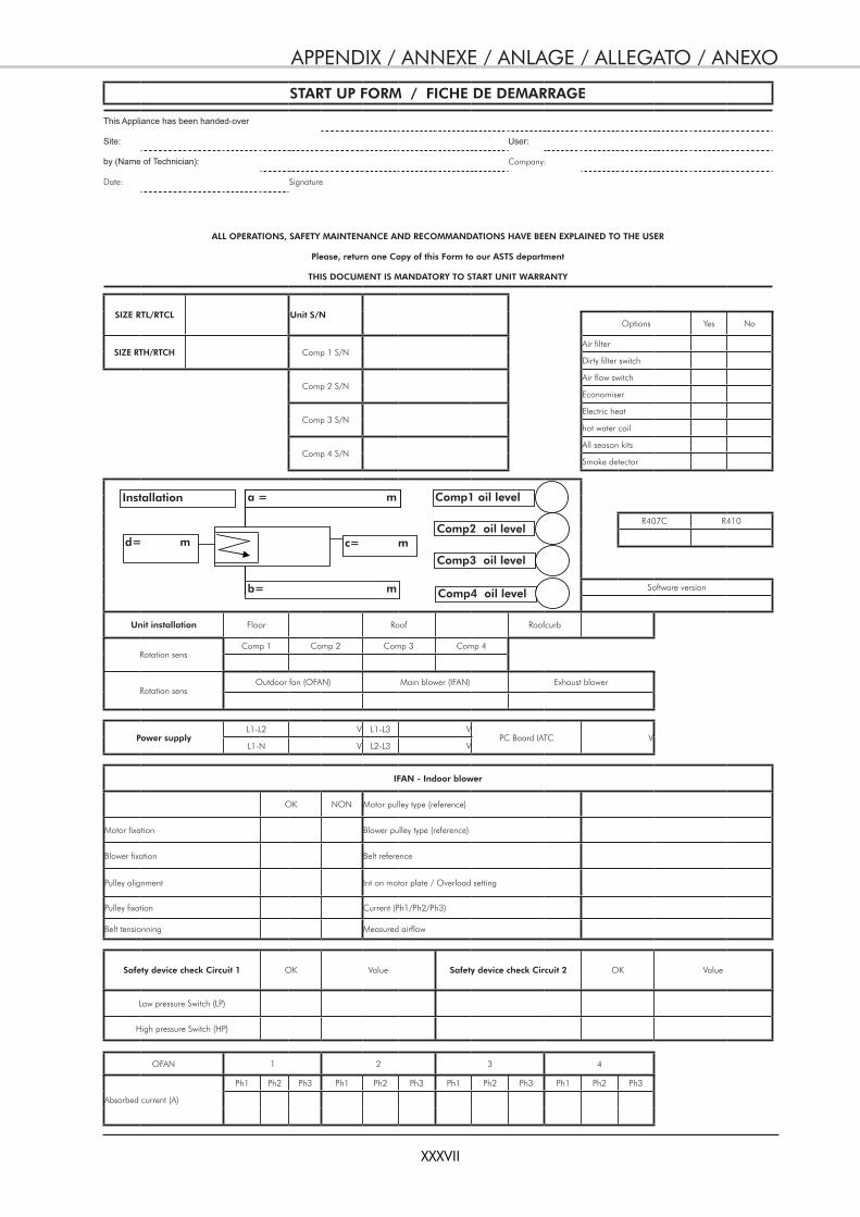
APPENDIX / ANNEXE / ANLAGE / ALLEGATO / ANEXO
XXXVII
START UP FORM / FICHE DE DEMARRAGE
This Appliance has been handed-over
Site: User:
by (Name of Technician): Company:
Date: Signature
ALL OPERATIONS, SAFETY MAINTENANCE AND RECOMMANDATIONS HAVE BEEN EXPLAINED TO THE USER
Please, return one Copy of this Form to our ASTS department
THIS DOCUMENT IS MANDATORY TO START UNIT WARRANTY
SIZE RTL/RTCL Unit S/NOptions Yes No
SIZE RTH/RTCH Comp 1 S/NAir filter
Dirty filter switch
Comp 2 S/NAir flow switch
Economiser
Comp 3 S/NElectric heat
hot water coil
Comp 4 S/NAll season kits
Smoke detector
R407C R410
Software version
Unit installation Floor Roof Roofcurb
Rotation sensComp 1 Comp 2 Comp 3 Comp 4
Rotation sensOutdoor fan (OFAN) Main blower (IFAN) Exhaust blower
Power supplyL1-L2 V L1-L3 V
PC Board IATC VL1-N V L2-L3 V
IFAN - Indoor blower
OK NON Motor pulley type (reference)
Motor fixation Blower pulley type (reference)
Blower fixation Belt reference
Pulley alignment Int on motor plate / Overload setting
Pulley fixation Current (Ph1/Ph2/Ph3)
Belt tensionning Measured airflow
Safety device check Circuit 1 OK Value Safety device check Circuit 2 OK Value
Low pressure Switch (LP)
High pressure Switch (HP)
OFAN 1 2 3 4
Absorbed current (A)
Ph1 Ph2 Ph3 Ph1 Ph2 Ph3 Ph1 Ph2 Ph3 Ph1 Ph2 Ph3
b= m
a = m
d= m
a = m
d= m c= m
a = m Comp1 oil level
Comp2 oil level
Comp3 oil level
Comp4 oil level
Installation
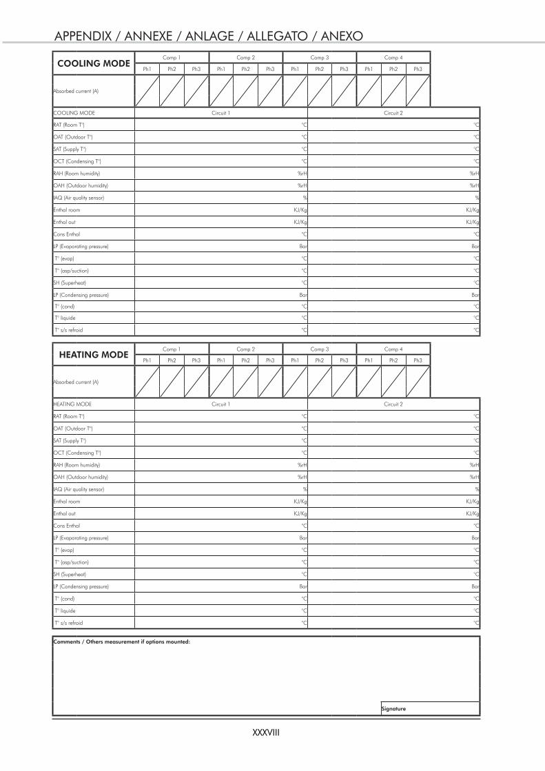
APPENDIX / ANNEXE / ANLAGE / ALLEGATO / ANEXO
XXXVIII
COOLING MODEComp 1 Comp 2 Comp 3 Comp 4
Ph1 Ph2 Ph3 Ph1 Ph2 Ph3 Ph1 Ph2 Ph3 Ph1 Ph2 Ph3
Absorbed current (A)
COOLING MODE Circuit 1 Circuit 2
RAT (Room T°) °C °C
OAT (Outdoor T°) °C °C
SAT (Supply T°) °C °C
OCT (Condensing T°) °C °C
RAH (Room humidity) %rH %rH
OAH (Outdoor humidity) %rH %rH
IAQ (Air quality sensor) % %
Enthal room KJ/Kg KJ/Kg
Enthal out KJ/Kg KJ/Kg
Cons Enthal °C °C
LP (Evaporating pressure) Bar Bar
T° (evap) °C °C
T° (asp/suction) °C °C
SH (Superheat) °C °C
LP (Condensing pressure) Bar Bar
T° (cond) °C °C
T° liquide °C °C
T° s/s refroid °C °C
HEATING MODEComp 1 Comp 2 Comp 3 Comp 4
Ph1 Ph2 Ph3 Ph1 Ph2 Ph3 Ph1 Ph2 Ph3 Ph1 Ph2 Ph3
Absorbed current (A)
HEATING MODE Circuit 1 Circuit 2
RAT (Room T°) °C °C
OAT (Outdoor T°) °C °C
SAT (Supply T°) °C °C
OCT (Condensing T°) °C °C
RAH (Room humidity) %rH %rH
OAH (Outdoor humidity) %rH %rH
IAQ (Air quality sensor) % %
Enthal room KJ/Kg KJ/Kg
Enthal out KJ/Kg KJ/Kg
Cons Enthal °C °C
LP (Evaporating pressure) Bar Bar
T° (evap) °C °C
T° (asp/suction) °C °C
SH (Superheat) °C °C
LP (Condensing pressure) Bar Bar
T° (cond) °C °C
T° liquide °C °C
T° s/s refroid °C °C
Comments / Others measurement if options mounted:
Signature
And that the following paragraphs of the harmonised standards have been applied.Et que les paragraphes suivants les normes harmonisées ont été appliqués.
Und dass die folgenden Paragraphen der vereinheitlichten Normen Angewandt wurden.E che sono stati applicati i seguenti paragraphi delle norme armonnizzate.
Y que se han aplicado los siguientes apartados de las normas armonizadas.
RT 40 - 50 - 60 - 70 - 80 - 100 -110
MACHINERY DIRECTIVE 98 / 37 / EECLOW VOLTAGE DIRECTIVE (DBT) 2006 / 95 / EEC
ELECTROMAGNETIC COMPATIBILITY DIRECTIVE 89 / 336 / EEC AMENDED BY DIRECTIVE 92 / 31 / EEC AND 93 / 68 / EECPRESSURISE EQUIPMENT DIRECTIVE (DESP) 97 / 23 / EEC
SUB-MODULE A CATEGORY I: RT40 SUB-MODULE A1 CATEGORY II: RT50 - RT60 - RT70 - RT80 - RT100 - RT110
NOTIFIED BODY: TÜV RHEINLAND – 6, RUE HALÉVY – 75 009 PARIS - FRANCE.THE PRODUCTS ARE PROVIDED WITH CE 0035 MARKING OF CONFORMITY
DIRECTIVE MACHINES 98 / 37 C.E.E.DIRECTIVE BASSE TENSION (DBT) 2006 / 95 / C.E.E.
DIRECTIVE COMPATIBILITE ELECTROMAGNETIQUE 89 / 336 / C.E.E. AMENDEE PAR DIRECTIVE 92 / 31 / CEE ET 93 / 68 / CEEDIRECTIVE DES EQUIPEMENTS SOUS PRESSION (DESP) 97 / 23 C.E.E.
SOUS-MODULE A CATEGORIE I : RT40 SOUS-MODULE A1 CATEGORIE II : RT50 - RT60 - RT70 - RT80 - RT100 - RT110
AVEC SURVEILLANCE PAR LE TUV RHEINLAND 6, RUE HALÉVY – 75 009 PARIS - FRANCE.LES PRODUITS SONT FOURNIS AVEC LE MARQUAGE DE CONFORMITE CE 0035
RICHTLINIE MASCHINEN 98 / 37 / EGRICHTLINIE NIERDERSPANNUNG (DBT) 2006 / 95 / EG
RICHTLINIE ELEKTROMAGNETISHE VERTRÄGLICHKEIT 89 / 336 / EG ABGEÄNDERT DURCH DIE RICHTLINIE 92 / 31 / EG UND 93 / 68 / EGRICHTLINIE FÜR AUSRÜSTUNGEN UNTER DRUCK (DESP) 97 / 23 / EG
UNTER MODUL A, KATEGORIE I : RT40 UNTER MODUL A1, KATEGORIE II : RT50 - RT60 - RT70 - RT80 - RT100 - RT110
MIT KONTROLLE DURCH DEN TUV RHEINLAND 6, RUE HALÉVY – 75 009 PARIS - FRANCE.DIE PRODUKTE WERDEN MIT DER MARKIERUNG CONFORMITE CE 0035 GELIEFERT.
DIRETTIVA MACHINE 98 / 37 / CEEDIRETTIVA BASSA TENSIONE (DBT) 2006 / 95 / CEE
DIRETTIVA COMPATIBILITA ELETTROMAGNATICA 89 / 336 / CEE EMENDATA DALLA DIRETTIVA 92 / 31 /CEE E 93 / 68 / CEEDIRETTIVA DEGLI IMPIANTI SOTTO PRESSIONE (DESP) 97 / 23 / CEE
SOTTOMODULO A, CATEGORIA I : RT40 SOTTOMODULO A1, CATEGORIA II : RT50 - RT60 - RT70 - RT80 - RT100 - RT110
CON SUPERVISION POR EL TUV RHEINLAND 6, RUE HALÉVY – 75 009 PARIS - FRANCE.I PRODOTTI SONO FORNITI CON LA MARCATURA DI CONFORMITE CE 0035.
DIRECTIVA MAQUIAS 98 / 37 / CEEDIRECTIVA BAJA TENSION (DBT) 2006 / 95 / CEE
DIRECTIVA COMPATIBILIDAD ELECTROMAGNETICA 89 / 336 / CEE ENMENDATA POR LA DIRECTIVA 92 / 31 / CEE Y 93 / 68 / CEEDIRECTIVA DE LOS EQUIPOS A PRESION (DESP) 97 / 23 / CEE
BAJA MODULO A, CATEGORIA I : RT40 BAJA MODULO A1, CATEGORIA II : RT50 - RT60 - RT70 - RT80 - RT100 - RT110
CON SORVEGLIANZA DAL TUV RHEINLAND 6, RUE HALÉVY – 75 009 PARIS - FRANCE.LOS PRODUCTOS SE PROPORCIONAN CON EL MARCADO DE CONFOR CE 0035.
Déclaration CE de conformitéNous déclarons sous notre responsabilité que les produits désignés dans la présente notice sont conformes aux dispositions des directives CEE énoncées
ci- après et aux législations nationales les transposant.
EC Compliance declarationUnder our own responsibility, we declare that the product designated in this manual comply with the provisions of the EEC directives listed hereafter
and with the national legislation into which these directives have been transposed.
EG-KonformitätserklärungWir erklarën in eigener Verantwortung, das die in der vorliegenden Beschreibung angegebenen Produkte den Bestimungen der nachstehend
erwähnten EG-Richtlinien und den nationalen Gesetzesvorschriffen entsprechen, in denen diese Richtinien umgesetz sind.
Dichiarazione CE di conformitàDichiariamo, assurmendone la responsasabilità, che i prodotti descritti nel presente manuale sono conformi alle disposizioni delle direttive CEE di cui
sott e alle lagislazionni nazionali che li recepiscono
Declaramos, bajo nuestra responsabilidad, que los productos designados en este manual son conformes a las disposiciones de las directivas CEE enunuciadas a continuacion, asi como a las legislaciones nacionales que las contemplan.
Declaración CE de conformidad
EN 60 204-1 EN 61 000-6-2 EN61 000-6-4 EN 378-1 EN 378-2
A Tillières Sur Avre27570 - FRANCELe: 20/06/2007Franck BaillyQuality ManagerACE Industrie

As part of our ongoing product improvement programme, our products are subject to change without prior notice. Non contractual photos.
Dans un souci d’amélioration constante, nos produits peuvent être modifiés sans préavis. Photos non contractuelles.
In dem Bemühen um ständige Verbesserung können unsere Erzeugnisse ohne vorherige Ankündigung geändert werden. Fotos nicht vertraglich bindend.
A causa della politica di continua miglioria posta in atto dal costruttore, questi prodotti sono soggetti a modifiche senza alcun obbligo di preavviso. Le foto pubblicate non danno luogo ad alcun vincolo contrattuale.
Con objeto de mejorar constantemente, nuestros productos pueden ser modificados sin previo aviso. Fotos no contractuales.
ACE INDUSTRIERoute de Verneuil27570 Tillières-sur-AvreFRANCE� : +33 (0)2 32 60 61 00� : +33 (0)2 32 32 55 13