Rock support in the Kiirunavaara Mine
10
Ground Support 2013 — Y. Potvin and B. Brady (eds) © 2013 Australian Centre for Geomechanics, Perth, ISBN 978-0-9806154-7-0 Ground Support 2013, Perth, Australia 401 Rock support in the Kiirunavaara Mine L. Jacobsson Luossavaara–Kiirunavaara AB, Sweden J. Töyrä Luossavaara–Kiirunavaara AB, Sweden B. Woldemedhin Luossavaara–Kiirunavaara AB, Sweden H. Krekula Luossavaara–Kiirunavaara AB, Sweden Abstract The Kiirunavaara Mine in northern Sweden consists of one 4 km long iron orebody. The orebody is mined using large scale sublevel caving. Since 2008 the Kiirunavaara Mine has been considered a seismically active mine and as a consequence, several measures have been implemented in the mine to manage seismicity. These include: a comprehensive seismic monitoring system, mining sequences which mitigate the risk of larger seismic events, rock support designed for dynamic loads, and construction of a more comprehensive geological model. This paper describes how the rock support has been developed at Loussavaara-Kiirunavaara AB (LKAB) in recent years to deal with the problems arising from mining at greater depth in a seismically active mine. In summary, LKAB has developed rock support for various conditions and locations within the mine; this includes rock support in areas prone to mining induced seismicity. This paper also describes the rock support cycle from blasting through to the completion of installation. Finally, the paper includes a review of rock support engineering from 2008 until 2012 in terms of rockfalls (number and size) related to the amount of rock support used in the mine. The results indicate that the number and size of rockfalls have decreased mainly because of the improved rock support system. 1 Introduction The Kiirunavaara Mine is an iron ore mine owned by LKAB and is located in the city of Kiruna, approximately 150 km north of the Arctic Circle in the north of Sweden. The Kiirunavaara Mine orebody is approximately 4 km long and 80 m wide and strikes nearly north-south, dipping 55–60˚ towards the east. Underground mining is conducted only by large-scale sublevel caving, with an annual production of 28 Mt of crude ore, as of 2012. The mine is divided into 10 production blocks and each block has its own system of ore passes and ventilation shafts. Each shares an access ramp with the neighbouring block (Figure 1). Mining is ongoing on the 964–993 Levels. As mining progresses at depth, the magnitude of the rock stress increases. Since the orebody is 4 km long and steeply dipping, stress concentrations emerge underneath the orebody, and peak approximately 1−2 levels beneath the production level. The major (mining induced) principal stress beneath the orebody is approximately two times the virgin stress state (Figure 2). The major principal stress reaches its peak at approximately 1–2 levels under the current production level. The demand on the rock support system has changed over time, and since 2008 the standard for rock support at Kiirunavaara Mine has included rock support designed to withstand seismically induced dynamic load. doi:10.36487/ACG_rep/1304_26_Jacobsson
Transcript of Rock support in the Kiirunavaara Mine
Ground Support 2013 — Y. Potvin and B. Brady (eds) © 2013 Australian Centre for Geomechanics, Perth, ISBN 978-0-9806154-7-0
Ground Support 2013, Perth, Australia 401
Rock support in the Kiirunavaara Mine
L. Jacobsson Luossavaara–Kiirunavaara AB, Sweden
J. Töyrä Luossavaara–Kiirunavaara AB, Sweden
B. Woldemedhin Luossavaara–Kiirunavaara AB, Sweden
H. Krekula Luossavaara–Kiirunavaara AB, Sweden
Abstract
The Kiirunavaara Mine in northern Sweden consists of one 4 km long iron orebody. The orebody is mined using large scale sublevel caving. Since 2008 the Kiirunavaara Mine has been considered a seismically active mine and as a consequence, several measures have been implemented in the mine to manage seismicity. These include: a comprehensive seismic monitoring system, mining sequences which mitigate the risk of larger seismic events, rock support designed for dynamic loads, and construction of a more comprehensive geological model.
This paper describes how the rock support has been developed at Loussavaara-Kiirunavaara AB (LKAB) in recent years to deal with the problems arising from mining at greater depth in a seismically active mine. In summary, LKAB has developed rock support for various conditions and locations within the mine; this includes rock support in areas prone to mining induced seismicity. This paper also describes the rock support cycle from blasting through to the completion of installation. Finally, the paper includes a review of rock support engineering from 2008 until 2012 in terms of rockfalls (number and size) related to the amount of rock support used in the mine. The results indicate that the number and size of rockfalls have decreased mainly because of the improved rock support system.
1 Introduction
The Kiirunavaara Mine is an iron ore mine owned by LKAB and is located in the city of Kiruna, approximately 150 km north of the Arctic Circle in the north of Sweden. The Kiirunavaara Mine orebody is approximately 4 km long and 80 m wide and strikes nearly north-south, dipping 55–60˚ towards the east. Underground mining is conducted only by large-scale sublevel caving, with an annual production of 28 Mt of crude ore, as of 2012.
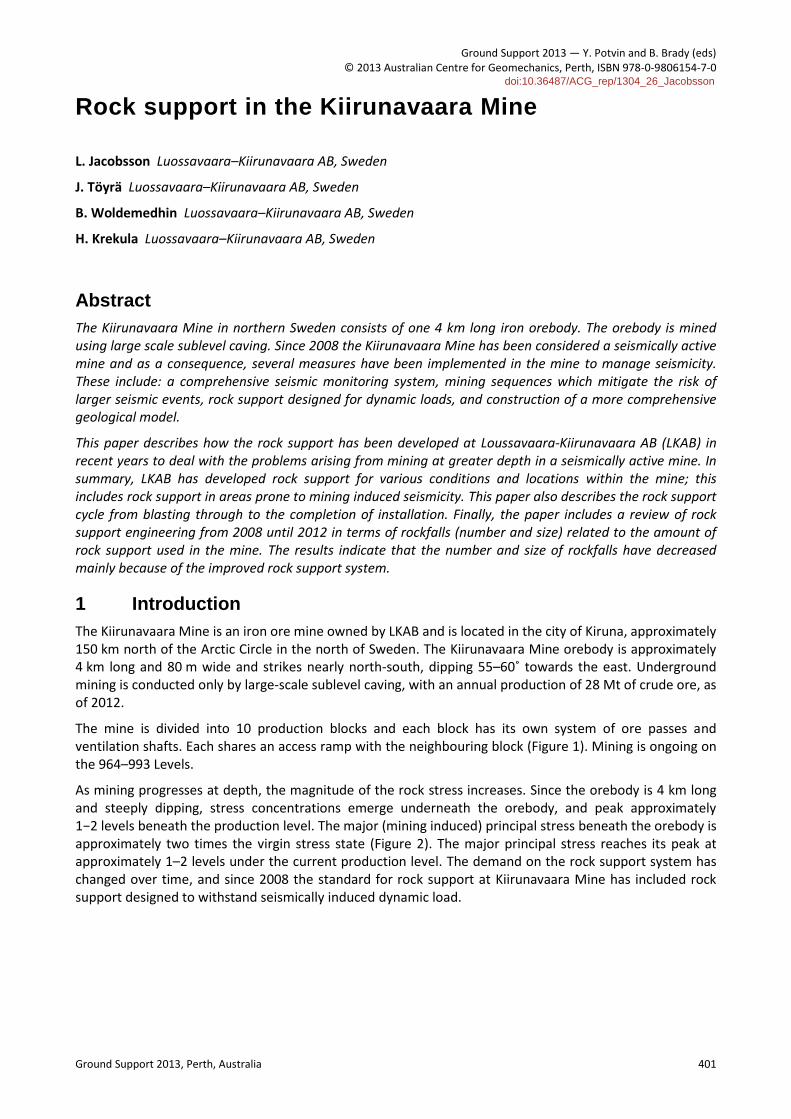
The mine is divided into 10 production blocks and each block has its own system of ore passes and ventilation shafts. Each shares an access ramp with the neighbouring block (Figure 1). Mining is ongoing on the 964–993 Levels.
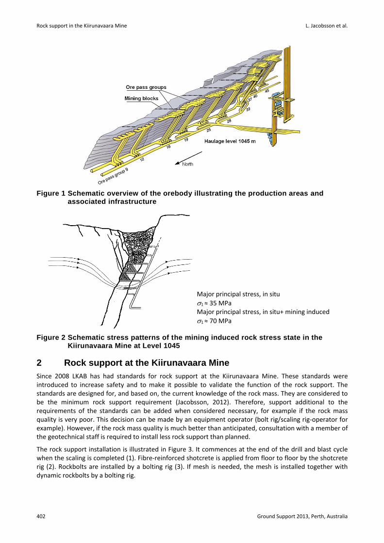
As mining progresses at depth, the magnitude of the rock stress increases. Since the orebody is 4 km long and steeply dipping, stress concentrations emerge underneath the orebody, and peak approximately 1−2 levels beneath the production level. The major (mining induced) principal stress beneath the orebody is approximately two times the virgin stress state (Figure 2). The major principal stress reaches its peak at approximately 1–2 levels under the current production level. The demand on the rock support system has changed over time, and since 2008 the standard for rock support at Kiirunavaara Mine has included rock support designed to withstand seismically induced dynamic load.
doi:10.36487/ACG_rep/1304_26_Jacobsson
Rock support in the Kiirunavaara Mine L. Jacobsson et al.
402 Ground Support 2013, Perth, Australia
Figure 1 Schematic overview of the orebody illustrating the production areas and associated infrastructure
Figure 2 Schematic stress patterns of the mining induced rock stress state in the Kiirunavaara Mine at Level 1045
2 Rock support at the Kiirunavaara Mine
Since 2008 LKAB has had standards for rock support at the Kiirunavaara Mine. These standards were introduced to increase safety and to make it possible to validate the function of the rock support. The standards are designed for, and based on, the current knowledge of the rock mass. They are considered to be the minimum rock support requirement (Jacobsson, 2012). Therefore, support additional to the requirements of the standards can be added when considered necessary, for example if the rock mass quality is very poor. This decision can be made by an equipment operator (bolt rig/scaling rig-operator for example). However, if the rock mass quality is much better than anticipated, consultation with a member of the geotechnical staff is required to install less rock support than planned.
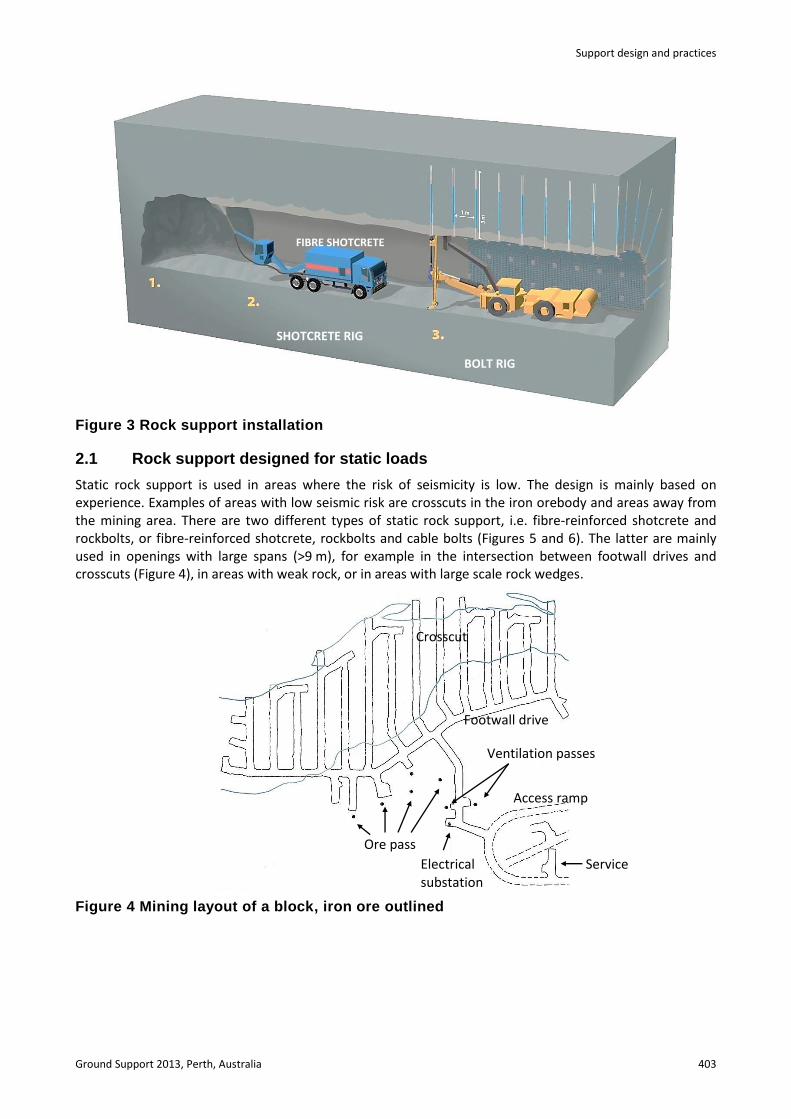
The rock support installation is illustrated in Figure 3. It commences at the end of the drill and blast cycle when the scaling is completed (1). Fibre-reinforced shotcrete is applied from floor to floor by the shotcrete rig (2). Rockbolts are installed by a bolting rig (3). If mesh is needed, the mesh is installed together with dynamic rockbolts by a bolting rig.
Major principal stress, in situ
1 ≈ 35 MPa Major principal stress, in situ+ mining induced
1 ≈ 70 MPa
Support design and practices
Ground Support 2013, Perth, Australia 403
Figure 3 Rock support installation
2.1 Rock support designed for static loads
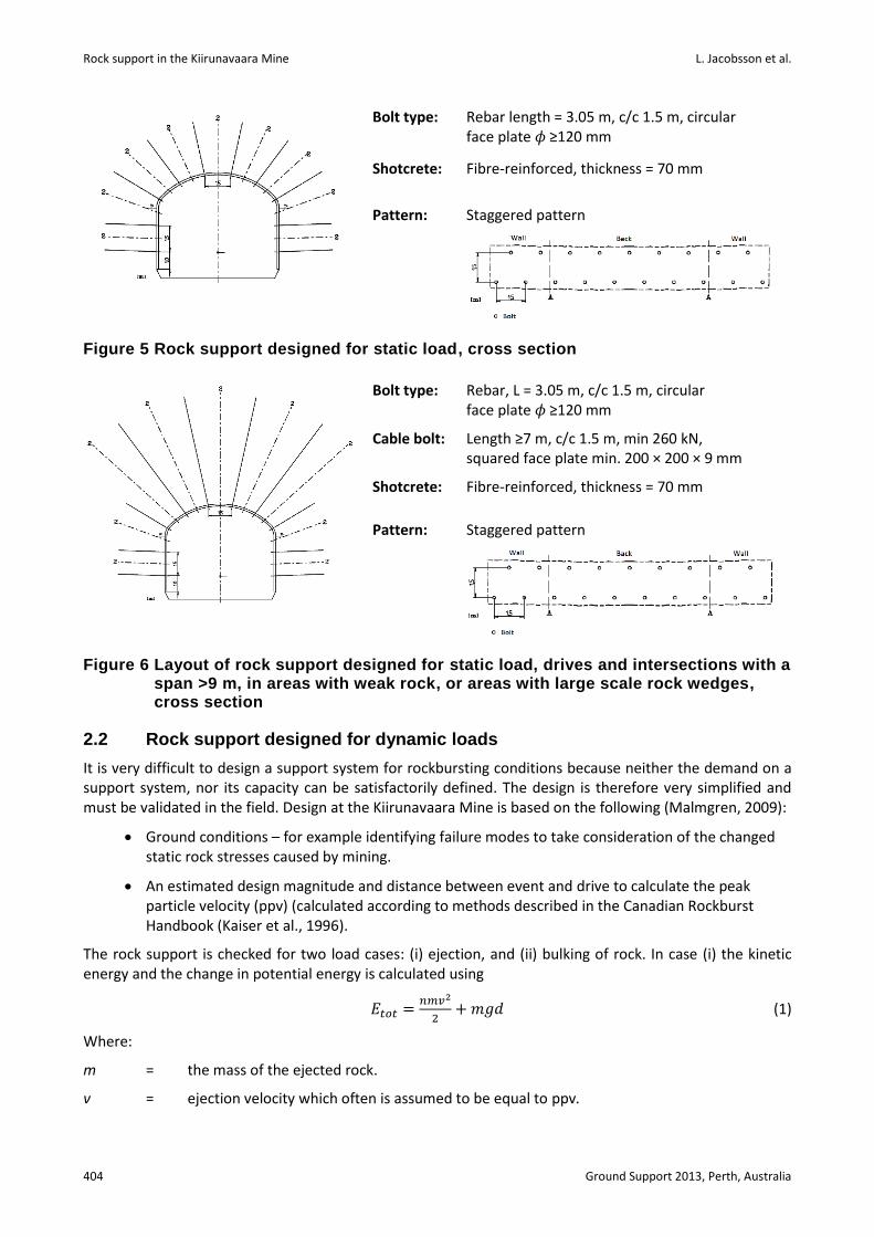
Static rock support is used in areas where the risk of seismicity is low. The design is mainly based on experience. Examples of areas with low seismic risk are crosscuts in the iron orebody and areas away from the mining area. There are two different types of static rock support, i.e. fibre-reinforced shotcrete and rockbolts, or fibre-reinforced shotcrete, rockbolts and cable bolts (Figures 5 and 6). The latter are mainly used in openings with large spans (>9 m), for example in the intersection between footwall drives and crosscuts (Figure 4), in areas with weak rock, or in areas with large scale rock wedges.
Figure 4 Mining layout of a block, iron ore outlined
Crosscut
Footwall drive
Access ramp
Service area
Ventilation passes
Ore pass
Electrical substation
FIBRE SHOTCRETE
SHOTCRETE RIG
BOLT RIG
Rock support in the Kiirunavaara Mine L. Jacobsson et al.
404 Ground Support 2013, Perth, Australia
Bolt type: Rebar length = 3.05 m, c/c 1.5 m, circular face plate 𝜙 ≥120 mm
Shotcrete: Fibre-reinforced, thickness = 70 mm
Pattern: Staggered pattern
Figure 5 Rock support designed for static load, cross section
Bolt type: Rebar, L = 3.05 m, c/c 1.5 m, circular face plate 𝜙 ≥120 mm
Cable bolt: Length ≥7 m, c/c 1.5 m, min 260 kN, squared face plate min. 200 × 200 × 9 mm
Shotcrete: Fibre-reinforced, thickness = 70 mm
Pattern: Staggered pattern
Figure 6 Layout of rock support designed for static load, drives and intersections with a span >9 m, in areas with weak rock, or areas with large scale rock wedges, cross section
2.2 Rock support designed for dynamic loads
It is very difficult to design a support system for rockbursting conditions because neither the demand on a support system, nor its capacity can be satisfactorily defined. The design is therefore very simplified and must be validated in the field. Design at the Kiirunavaara Mine is based on the following (Malmgren, 2009):
Ground conditions – for example identifying failure modes to take consideration of the changed static rock stresses caused by mining.
An estimated design magnitude and distance between event and drive to calculate the peak particle velocity (ppv) (calculated according to methods described in the Canadian Rockburst Handbook (Kaiser et al., 1996).
The rock support is checked for two load cases: (i) ejection, and (ii) bulking of rock. In case (i) the kinetic energy and the change in potential energy is calculated using
𝐸𝑡𝑜𝑡 =𝑛𝑚𝑣2
2+𝑚𝑔𝑑 (1)
Where:
m = the mass of the ejected rock.
v = ejection velocity which often is assumed to be equal to ppv.
Support design and practices
Ground Support 2013, Perth, Australia 405
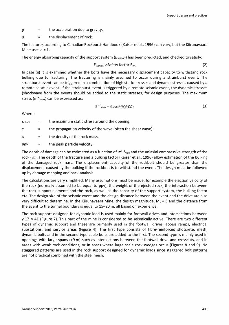
g = the acceleration due to gravity.
d = the displacement of rock.
The factor n, according to Canadian Rockburst Handbook (Kaiser et al., 1996) can vary, but the Kiirunavaara Mine uses n = 1.
The energy absorbing capacity of the support system (Esupport) has been predicted, and checked to satisfy:
Esupport >Safety factor∙Etot (2)
In case (ii) it is examined whether the bolts have the necessary displacement capacity to withstand rock bulking due to fracturing. The fracturing is mainly assumed to occur during a strainburst event. The strainburst event can be triggered in a combination of high static stresses and dynamic stresses caused by a remote seismic event. If the strainburst event is triggered by a remote seismic event, the dynamic stresses (shockwave from the event) should be added to the static stresses, for design purposes. The maximum
stress (s+dmax) can be expressed as:
s+dmax = Static+4cppv (3)
Where:
Static = the maximum static stress around the opening.
c = the propagation velocity of the wave (often the shear wave).
= the density of the rock mass.
ppv = the peak particle velocity.
The depth of damage can be estimated as a function of s+dmax and the uniaxial compressive strength of the
rock (c). The depth of the fracture and a bulking factor (Kaiser et al., 1996) allow estimation of the bulking of the damaged rock mass. The displacement capacity of the rockbolt should be greater than the displacement caused by the bulking if the rockbolt is to withstand the event. The design must be followed up by damage mapping and back-analysis.
The calculations are very simplified. Many assumptions must be made; for example the ejection velocity of the rock (normally assumed to be equal to ppv), the weight of the ejected rock, the interaction between the rock support elements and the rock, as well as the capacity of the support system, the bulking factor etc. The design size of the seismic event and the design distance between the event and the drive are also very difficult to determine. In the Kiirunavaara Mine, the design magnitude, ML = 3 and the distance from the event to the tunnel boundary is equal to 15–20 m, all based on experience.
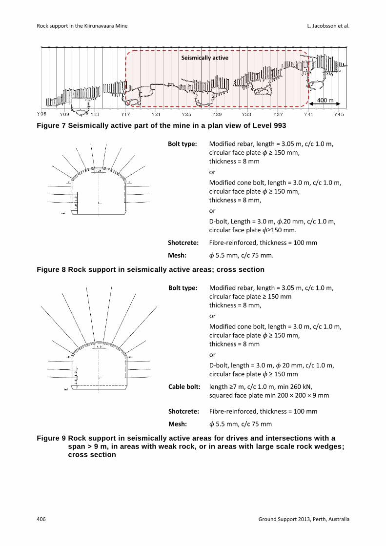
The rock support designed for dynamic load is used mainly for footwall drives and intersections between y 17–y 41 (Figure 7). This part of the mine is considered to be seismically active. There are two different types of dynamic support and these are primarily used in the footwall drives, access ramps, electrical substations, and service areas (Figure 4). The first type consists of fibre-reinforced shotcrete, mesh, dynamic bolts and in the second type cable bolts are added to the first. The second type is mainly used in openings with large spans (>9 m) such as intersections between the footwall drive and crosscuts, and in areas with weak rock conditions, or in areas where large scale rock wedges occur (Figures 8 and 9). No staggered patterns are used in the rock support designed for dynamic loads since staggered bolt patterns are not practical combined with the steel mesh.
Rock support in the Kiirunavaara Mine L. Jacobsson et al.
406 Ground Support 2013, Perth, Australia
Figure 7 Seismically active part of the mine in a plan view of Level 993
Figure 8 Rock support in seismically active areas; cross section
Bolt type: Modified rebar, length = 3.05 m, c/c 1.0 m, circular face plate ≥ 150 mm thickness = 8 mm,
or
Modified cone bolt, length = 3.0 m, c/c 1.0 m, circular face plate 𝜙 ≥ 150 mm, thickness = 8 mm
or
D-bolt, length = 3.0 m, 𝜙 20 mm, c/c 1.0 m, circular face plate 𝜙 ≥ 150 mm
Cable bolt: length ≥7 m, c/c 1.0 m, min 260 kN, squared face plate min 200 × 200 × 9 mm
Shotcrete: Fibre-reinforced, thickness = 100 mm
Mesh: 𝜙 5.5 mm, c/c 75 mm
Figure 9 Rock support in seismically active areas for drives and intersections with a span > 9 m, in areas with weak rock, or in areas with large scale rock wedges; cross section
Bolt type: Modified rebar, length = 3.05 m, c/c 1.0 m, circular face plate 𝜙 ≥ 150 mm, thickness = 8 mm
or
Modified cone bolt, length = 3.0 m, c/c 1.0 m, circular face plate 𝜙 ≥ 150 mm, thickness = 8 mm,
or
D-bolt, Length = 3.0 m, 𝜙.20 mm, c/c 1.0 m, circular face plate 𝜙≥150 mm.
Shotcrete: Fibre-reinforced, thickness = 100 mm
Mesh: 𝜙 5.5 mm, c/c 75 mm.
400 m
Seismically active
Support design and practices
Ground Support 2013, Perth, Australia 407
3 The outcome of the rock support standards
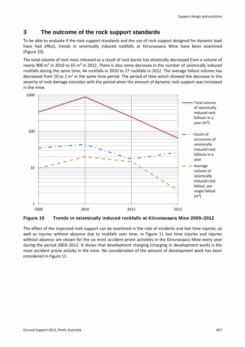
To be able to evaluate if the rock support standards and the use of rock support designed for dynamic load have had effect, trends in seismically induced rockfalls at Kiirunavaara Mine have been examined (Figure 10).
The total volume of rock mass released as a result of rock bursts has drastically decreased from a volume of nearly 900 m3 in 2010 to 65 m3 in 2012. There is also some decrease in the number of seismically induced rockfalls during the same time; 44 rockfalls in 2010 to 27 rockfalls in 2012. The average fallout volume has decreased from 10 to 2 m3 in the same time period. The period of time which showed the decrease in the severity of rock damage coincides with the period when the amount of dynamic rock support was increased in the mine.
Figure 10 Trends in seismically induced rockfalls at Kiirunavaara Mine 2009–2012
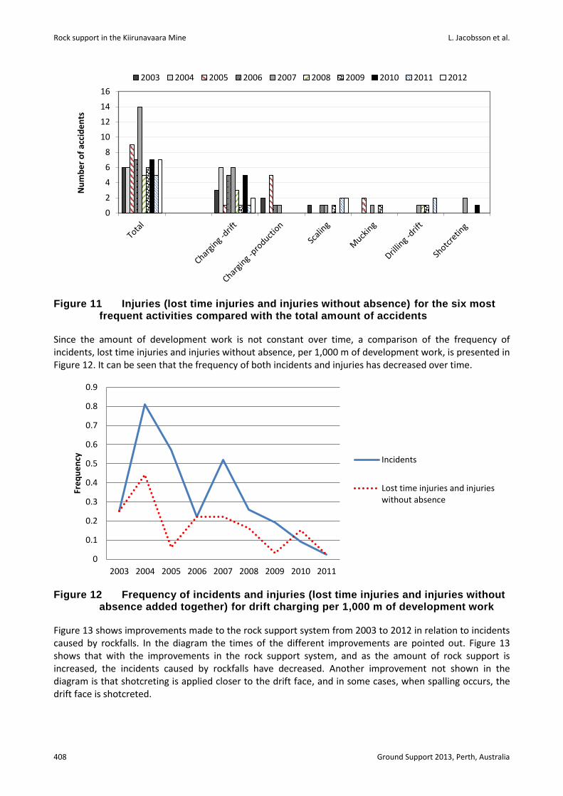
The effect of the improved rock support can be examined in the rate of incidents and lost time injuries, as well as injuries without absence due to rockfalls over time. In Figure 11 lost time injuries and injuries without absence are shown for the six most accident prone activities in the Kiirunavaara Mine every year during the period 2003–2012. It shows that development charging (charging in development work) is the most accident prone activity in the mine. No consideration of the amount of development work has been considered in Figure 11.
1
10
100
1000
2009 2010 2011 2012
Total volumeof seismicallyinduced rockfallouts in ayear (m³)
Count ofoccurence ofseismicallyinduced rockfallouts in ayear
Averagevolume ofseismicallyinduced rockfallout persingle fallout(m³)
Rock support in the Kiirunavaara Mine L. Jacobsson et al.
408 Ground Support 2013, Perth, Australia
Figure 11 Injuries (lost time injuries and injuries without absence) for the six most frequent activities compared with the total amount of accidents
Since the amount of development work is not constant over time, a comparison of the frequency of incidents, lost time injuries and injuries without absence, per 1,000 m of development work, is presented in Figure 12. It can be seen that the frequency of both incidents and injuries has decreased over time.
Figure 12 Frequency of incidents and injuries (lost time injuries and injuries without absence added together) for drift charging per 1,000 m of development work
Figure 13 shows improvements made to the rock support system from 2003 to 2012 in relation to incidents caused by rockfalls. In the diagram the times of the different improvements are pointed out. Figure 13 shows that with the improvements in the rock support system, and as the amount of rock support is increased, the incidents caused by rockfalls have decreased. Another improvement not shown in the diagram is that shotcreting is applied closer to the drift face, and in some cases, when spalling occurs, the drift face is shotcreted.
0
2
4
6
8
10
12
14
16N
um
be
r o
f ac
cid
en
ts2003 2004 2005 2006 2007 2008 2009 2010 2011 2012
0
0.1
0.2
0.3
0.4
0.5
0.6
0.7
0.8
0.9
2003 2004 2005 2006 2007 2008 2009 2010 2011
Fre
qu
en
cy Incidents
Lost time injuries and injurieswithout absence

Support design and practices
Ground Support 2013, Perth, Australia 409
Figure 13 Improved rock support in relation to incidents during 2003–2011
4 Conclusions
Since 2008 several measures have been implemented in the Kiirunavaara Mine to improve safety against rockfalls. While the number of seismically induced rockfalls has only decreased slightly, a larger change in the volume of rockfalls occurred. A notable decrease in both average volume per rockfall and total volume was observed.
Another indicator of the performance of the rock support system used at LKAB Kiirunavaara Mine has been to examine incidents and injuries (lost time injuries and injuries without absence) caused by rockfalls. Both injuries and incidents have decreased since 2008, especially when comparing them per 1,000 m of development work.
These results indicate that the measures that have been implemented have increased the safety against rock fallouts. The work does not end here, the Kiirunavaara Mine will continue the work, and the aim is to get a cost efficient rock support system with the correct amount of rock support as well as improved installation time. Work regarding the seismic system includes automated processing for the seismic events to improve the accuracy in locating the events, as well as shortening the time to process the data.
References
Jacobsson, L. (2012) LKAB Standards for rock support, Internal report, Luossavaara–Kiirunavaara AB. Kaiser, P.K., McCreath, D.R. and Tannant, D.D. (1996) Canadian Rockburst Support Handbook, Geomechanics Research Centre,
Laurentian University, Sudbury. Malmgren, L. (2009) Control of the load capacity of rock support designed for dynamic load, Internal report, Luossavaara–
Kiirunavaara AB.
97
63
134
108
152
130
101
61 60
71
0
20
40
60
80
100
120
140
160
180
200
0
100
200
300
400
500
600
2003 2004 2005 2006 2007 2008 2009 2010 2011 2012
Number of incidentsShotcrete (m3)
Incidents
Shotcrete
Dynamic rock support
Bolt 3.05 m
Fibre schotcrete
Alkali-free accelerator
Cablebolt with face plate
Seismic monitoring
x 100
Increased amount of bolts
Rock support in the Kiirunavaara Mine L. Jacobsson et al.
410 Ground Support 2013, Perth, Australia