Plug fan ER..C, · Hz 0.55 ER22C-2DN.A7.1R 71M I 2800 1.31 4140 74 0.75 ER22C-2DN.B7.1R 80M II 2825...
36
52 www.ziehl-abegg.com Plug fan ER..C, ventilation unit GR..C 04/2011
Transcript of Plug fan ER..C, · Hz 0.55 ER22C-2DN.A7.1R 71M I 2800 1.31 4140 74 0.75 ER22C-2DN.B7.1R 80M II 2825...
52 www.ziehl-abegg.com
Plug fan ER..C, ventilation unit GR..C 04/2011
Product overview Page
Size 225 54
Size 250 56
Size 280 58
Size 315 60
Size 355 62
Size 400 64
Size 450 66
Size 500 68
Size 560 70
Size 630 72
Size 710 74
Size 800 76
Size 900 78
Size 1000 80
Size 1120 - version 4R 82
Size 1120 - version 1R 84
Plug fan ER..C, ventilation unit GR..C
53www.ziehl-abegg.com
RH
..C
pro
RH
..C
Ser
ies
E
R /
GR
ER
..C
pro
GR
..C
pro
Ex-
Des
ign
Sys
tem
C
ompo
nent
sA
ppen
dix
Info
rmat
ion
ER
..C
GR
..C
Plug fan ER..C, ventilation unit GR..C04/2011
1285
76
78
80
82
84
86
88
90
L WA
5 [d
B]
0 500 1.000 1.500 2.000 2.500 3.000 3.500
qV [m³/h]
4140
5200
min-1
4600
I
II
III
0
500
1.000
1.500
2.000
2.500
3.000
p sF [P
a]
1,1
1,5
PL kW
I
II
III
3630
4140
4600
5200
5940
min-1
50% 59%
65%
65%
56%
45%
37%
69%
5500
0,75
0,55
0,37
0,25
0,12 2800
3200
2450
2000
68%
69%
ηfaL
8548
8
Technical dataRated power Type Motor size Fan curve no. Rated speed Rated current Max. speed Max. frequencyPN ER / GR* nN IN nmax fmaxkW min-1 A min-1 Hz0.55 ER22C-2DN.A7.1R 71M I 2800 1.31 4140 740.75 ER22C-2DN.B7.1R 80M II 2825 1.62 4600 811.10 ER22C-2DN.B7.1R 80M III 2825 2.28 5200 92* Identical performance data for ER..C and GR..C
Basic version ER Basic version GR
Rated power Installation posi-tion H
Installation position Vu
Installation position Vo
PN Type Article no. Type Article no. Article no. Article no. kW ER..C ER..C max. GR..C GR..C GR..C GR..C max.
0.55 ER22C-2DN.A7.1R 130613/0F01 15 0.75 ER22C-2DN.B7.1R 130614/0F01 20 GR22C-2DN.B5.1R 113732/H01 113732/U01 113732/O01 191.10 ER22C-2DN.B7.1R 130615/0F01 21 GR22C-2DN.B5.1R 113733/H01 113733/U01 113733/O01 21
Inlet guard Page 109Rubber dampers Page 109Spring vibration damper Page 109Flexible air intakes Page 110Frequency inverter Icontrol Page 92Sensors Page 96
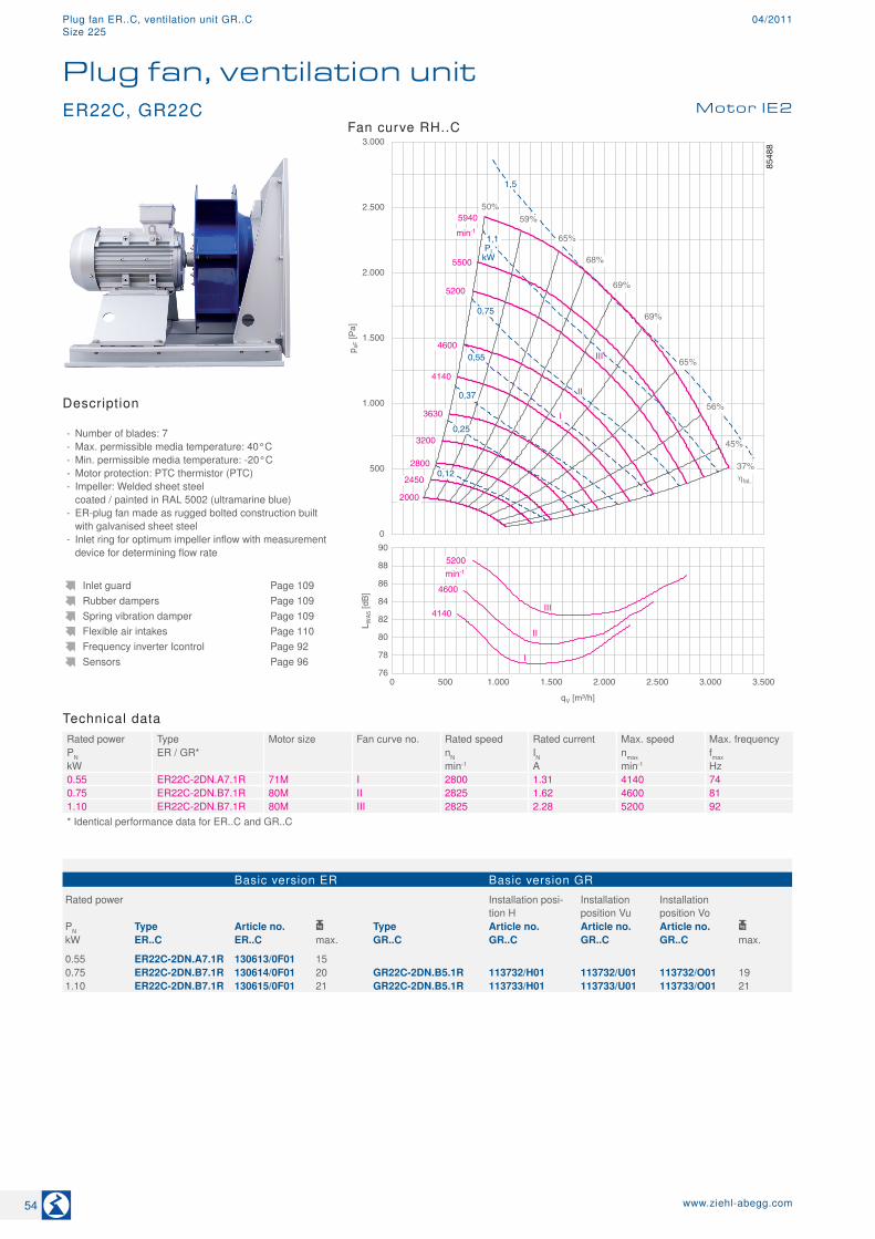
ER22C, GR22C Motor IE2
Plug fan, ventilation unit
Description
- Number of blades: 7 - Max. permissible media temperature: 40°C - Min. permissible media temperature: -20°C - Motor protection: PTC thermistor (PTC) - Impeller: Welded sheet steel coated / painted in RAL 5002 (ultramarine blue)
- ER-plug fan made as rugged bolted construction built with galvanised sheet steel
- Inlet ring for optimum impeller inflow with measurement device for determining flow rate
Fan curve RH..C
54 www.ziehl-abegg.com
Plug fan ER..C, ventilation unit GR..C 04/2011Size 225
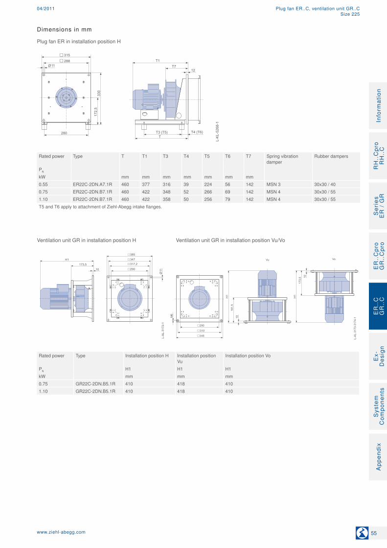
Dimensions in mm
Plug fan ER in installation position H
L-K
L-52
68-1
11Ø
280T
T1T7
T3 (T5)
330
172,
5
315288
12
T4 (T6)
Rated power Type T T1 T3 T4 T5 T6 T7 Spring vibration
damperRubber dampers
PN
kW mm mm mm mm mm mm mm0.55 ER22C-2DN.A7.1R 460 377 316 39 224 56 142 MSN 3 30x30 / 400.75 ER22C-2DN.B7.1R 460 422 348 52 266 69 142 MSN 4 30x30 / 551.10 ER22C-2DN.B7.1R 460 422 358 50 256 79 142 MSN 4 30x30 / 55T5 and T6 apply to attachment of Ziehl-Abegg intake flanges.
Ventilation unit GR in installation position H Ventilation unit GR in installation position Vu/Vo
L-AL-3173-3174-1
345
310
290
Vu Vo
L-AL-3172-1
385347
290
317,2
11Ø
H1
181,5
10
H1
173,5 10
H1173,5
10
M6
Rated power Type Installation position H Installation position Vu
Installation position Vo
PN H1 H1 H1kW mm mm mm0.75 GR22C-2DN.B5.1R 410 418 4101.10 GR22C-2DN.B5.1R 410 418 410
55www.ziehl-abegg.com
RH
..C
pro
RH
..C
Ser
ies
E
R /
GR
ER
..C
pro
GR
..C
pro
Ex-
Des
ign
Sys
tem
C
ompo
nent
sA
ppen
dix
Info
rmat
ion
ER
..C
GR
..C
Plug fan ER..C, ventilation unit GR..C04/2011Size 225
76
80
84
88
92
96
L WA
5 [d
B]
0 500 1.000 1.500 2.000 2.500 3.000 3.500 4.000 4.500
qV [m³/h]
3830
5350 min-1
4350
4800
I
II
III
IV
0
500
1.000
1.500
2.000
2.500
3.000
p sF [P
a]
1,5
2,2
PL kW
I
II
III
IV
3040
3470
3830
4350
5350
min-1
50% 58%
68%
65%
68%
60%
45%
37%
71%
4800
1,1
0,75
0,55
0,37
0,25
0,12 2030
2700
71%
71%
ηfaL
8551
9
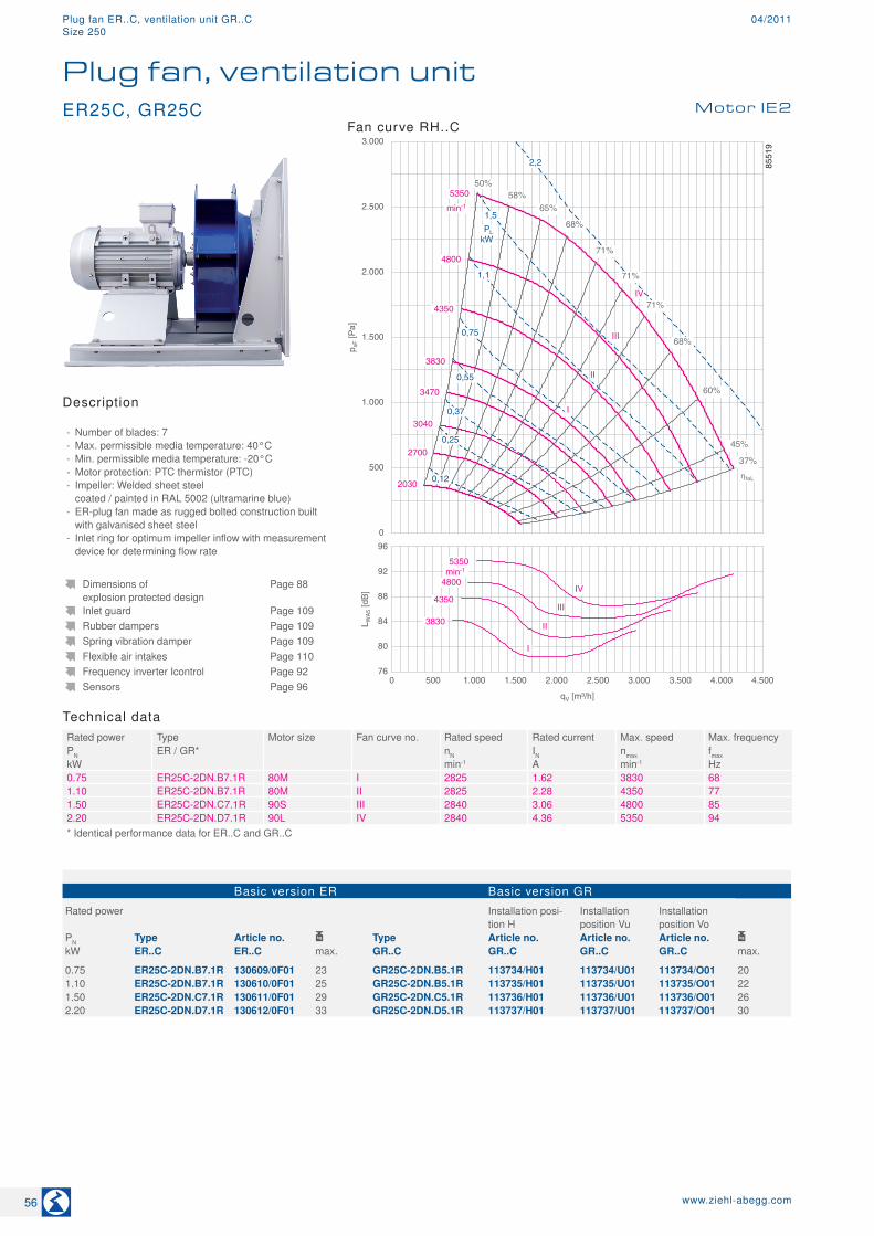
Technical dataRated power Type Motor size Fan curve no. Rated speed Rated current Max. speed Max. frequencyPN ER / GR* nN IN nmax fmaxkW min-1 A min-1 Hz0.75 ER25C-2DN.B7.1R 80M I 2825 1.62 3830 681.10 ER25C-2DN.B7.1R 80M II 2825 2.28 4350 771.50 ER25C-2DN.C7.1R 90S III 2840 3.06 4800 852.20 ER25C-2DN.D7.1R 90L IV 2840 4.36 5350 94* Identical performance data for ER..C and GR..C
Basic version ER Basic version GR
Rated power Installation posi-tion H
Installation position Vu
Installation position Vo
PN Type Article no. Type Article no. Article no. Article no. kW ER..C ER..C max. GR..C GR..C GR..C GR..C max.
0.75 ER25C-2DN.B7.1R 130609/0F01 23 GR25C-2DN.B5.1R 113734/H01 113734/U01 113734/O01 201.10 ER25C-2DN.B7.1R 130610/0F01 25 GR25C-2DN.B5.1R 113735/H01 113735/U01 113735/O01 221.50 ER25C-2DN.C7.1R 130611/0F01 29 GR25C-2DN.C5.1R 113736/H01 113736/U01 113736/O01 262.20 ER25C-2DN.D7.1R 130612/0F01 33 GR25C-2DN.D5.1R 113737/H01 113737/U01 113737/O01 30
Dimensions of explosion protected design
Page 88
Inlet guard Page 109Rubber dampers Page 109Spring vibration damper Page 109Flexible air intakes Page 110Frequency inverter Icontrol Page 92Sensors Page 96
ER25C, GR25C Motor IE2
Plug fan, ventilation unit
Description
- Number of blades: 7 - Max. permissible media temperature: 40°C - Min. permissible media temperature: -20°C - Motor protection: PTC thermistor (PTC) - Impeller: Welded sheet steel coated / painted in RAL 5002 (ultramarine blue)
- ER-plug fan made as rugged bolted construction built with galvanised sheet steel
- Inlet ring for optimum impeller inflow with measurement device for determining flow rate
Fan curve RH..C
56 www.ziehl-abegg.com
Plug fan ER..C, ventilation unit GR..C 04/2011Size 250

Dimensions in mm
Plug fan ER in installation position H
L-K
L-52
68-2
11Ø
360T
T1T7
T3 (T5)
415
215
400288
12
T4 (T6)
Rated power Type T T1 T3 T4 T5 T6 T7 Spring vibration
damperRubber dampers
PN
kW mm mm mm mm mm mm mm0.75 ER25C-2DN.B7.1R 460 439 330 61 252 80 158 MSN 4 30x30 / 551.10 ER25C-2DN.B7.1R 460 439 342 59 296 63 158 MSN 4 30x30 / 551.50 ER25C-2DN.C7.1R 460 464 362 63 322 65 158 MSN 4 30x30 / 552.20 ER25C-2DN.D7.1R 460 489 334 91 292 96 158 MSN 5 40x30 / 55T5 and T6 apply to attachment of Ziehl-Abegg intake flanges.
Ventilation unit GR in installation position H Ventilation unit GR in installation position Vu/Vo
L-AL-3173-3174-2
375
340
312
Vu Vo
L-AL-3172-2
400367
312
339,2
11Ø
H1
198
10
H1
190
10
H1190
10
M6
Rated power Type Installation position H Installation position Vu
Installation position Vo
PN H1 H1 H1kW mm mm mm0.75 GR25C-2DN.B5.1R 427 435 4271.10 GR25C-2DN.B5.1R 427 435 4271.50 GR25C-2DN.C5.1R 452 460 4522.20 GR25C-2DN.D5.1R 477 485 477
57www.ziehl-abegg.com
RH
..C
pro
RH
..C
Ser
ies
E
R /
GR
ER
..C
pro
GR
..C
pro
Ex-
Des
ign
Sys
tem
C
ompo
nent
sA
ppen
dix
Info
rmat
ion
ER
..C
GR
..C
Plug fan ER..C, ventilation unit GR..C04/2011Size 250

75
80
85
90
95
100
L WA
5 [d
B]
0 1.000 2.000 3.000 4.000 5.000 6.000
qV [m³/h]
3165
3560
4775 min-1
3940
4480
I
II III
IV
V
0
500
1.000
1.500
2.000
2.500
3.000
p sF [P
a]
1,5
2,2
PL
kW
I
II
III
IV
2500
3165
3560
3940
4775
min-1
50% 60%
71%
67%
59%
45%
37%
72%
71%
4480
1,1
0,75
0,55
0,37
0,25
0,12
2100
2850
V
3,0
1680
67%
ηfaL
8552
6
Technical dataRated power Type Motor size Fan curve no. Rated speed Rated current Max. speed Max. frequencyPN ER / GR* nN IN nmax fmaxkW min-1 A min-1 Hz0.75 ER28C-2DN.B7.1R 80M I 2825 1.62 3165 561.10 ER28C-2DN.B7.1R 80M II 2825 2.28 3560 631.50 ER28C-2DN.C7.1R 90S III 2840 3.06 3940 692.20 ER28C-2DN.D7.1R 90L IV 2840 4.36 4480 793.00 ER28C-2DN.E7.1R 100L V 2880 5.73 4775 83* Identical performance data for ER..C and GR..C
Basic version ER Basic version GR
Rated power Installation posi-tion H
Installation position Vu
Installation position Vo
PN Type Article no. Type Article no. Article no. Article no. kW ER..C ER..C max. GR..C GR..C GR..C GR..C max.
0.75 ER28C-2DN.B7.1R 130604/0F01 24 GR28C-2DN.B5.1R 113738/H01 113738/U01 113738/O01 231.10 ER28C-2DN.B7.1R 130605/0F01 26 GR28C-2DN.B5.1R 113739/H01 113739/U01 113739/O01 241.50 ER28C-2DN.C7.1R 130606/0F01 30 GR28C-2DN.C5.1R 113740/H01 113740/U01 113740/O01 282.20 ER28C-2DN.D7.1R 130607/0F01 34 GR28C-2DN.D5.1R 113741/H01 113741/U01 113741/O01 323.00 ER28C-2DN.E7.1R 130608/0F01 41 GR28C-2DN.E5.1R 113742/H01 113742/U01 113742/O01 38
Dimensions of explosion protected design
Page 88
Inlet guard Page 109Rubber dampers Page 109Spring vibration damper Page 109Flexible air intakes Page 110Frequency inverter Icontrol Page 92Sensors Page 96
ER28C, GR28C Motor IE2
Plug fan, ventilation unit
Description
- Number of blades: 7 - Max. permissible media temperature: 40°C - Min. permissible media temperature: -20°C - Motor protection: PTC thermistor (PTC) - Impeller: Welded sheet steel coated / painted in RAL 5002 (ultramarine blue)
- ER-plug fan made as rugged bolted construction built with galvanised sheet steel
- Inlet ring for optimum impeller inflow with measurement device for determining flow rate
Fan curve RH..C
58 www.ziehl-abegg.com
Plug fan ER..C, ventilation unit GR..C 04/2011Size 280

Dimensions in mm
Plug fan ER in installation position H
L-K
L-52
68-3
11Ø
360T
T1T7
T3 (T5)
415
215
400300
12
T4 (T6)
Rated power Type T T1 T3 T4 T5 T6 T7 Spring vibration
damperRubber dampers
PN
kW mm mm mm mm mm mm mm0.75 ER28C-2DN.B7.1R 460 455 350 61 302 63 174 MSN 4 30x30 / 401.10 ER28C-2DN.B7.1R 460 455 362 59 308 65 174 MSN 4 30x30 / 551.50 ER28C-2DN.C7.1R 460 480 350 80 306 82 174 MSN 4 30x30 / 552.20 ER28C-2DN.D7.1R 460 505 320 110 342 81 174 MSN 5 30x30 / 553.00 ER28C-2DN.E7.1R 570 543 468 59 428 64 174 MSN 5 40x30 / 55T5 and T6 apply to attachment of Ziehl-Abegg intake flanges.
Ventilation unit GR in installation position H Ventilation unit GR in installation position Vu/Vo
L-AL-3173-3174-3
405
370
345
Vu Vo
L-AL-3172-3
420390
345
367,2
11Ø
H1
217
10
H1
209,5 10
H1209,5
10
M6
Rated power Type Installation position H Installation position Vu
Installation position Vo
PN H1 H1 H1kW mm mm mm0.75 GR28C-2DN.B5.1R 443 450 4431.10 GR28C-2DN.B5.1R 443 450 4431.50 GR28C-2DN.C5.1R 468 475 4682.20 GR28C-2DN.D5.1R 493 500 4933.00 GR28C-2DN.E5.1R 531 538 531
59www.ziehl-abegg.com
RH
..C
pro
RH
..C
Ser
ies
E
R /
GR
ER
..C
pro
GR
..C
pro
Ex-
Des
ign
Sys
tem
C
ompo
nent
sA
ppen
dix
Info
rmat
ion
ER
..C
GR
..C
Plug fan ER..C, ventilation unit GR..C04/2011Size 280
3,0
0
500
1.000
1.500
2.000
2.500
3.000
p sF [P
a]
1,5
2,2
PL
kW
I
II
III
IV
2350
2950
3240
3690
4245 min-1
50% 60%
71%
67%
60%
45%
37%
72%
70%
4100
1,1
0,75
0,55
0,37
0,25 2040
2590
V
3,0
1730
4,0
75
80
85
90
95
100
L WA
5 [d
B]
0 1.000 2.000 3.000 4.000 5.000 6.000 7.000 8.000
qV [m³/h]
2950
3240
4245 min-1
3690
4100
I II
IIIIV
V
ηfaL
8552
7
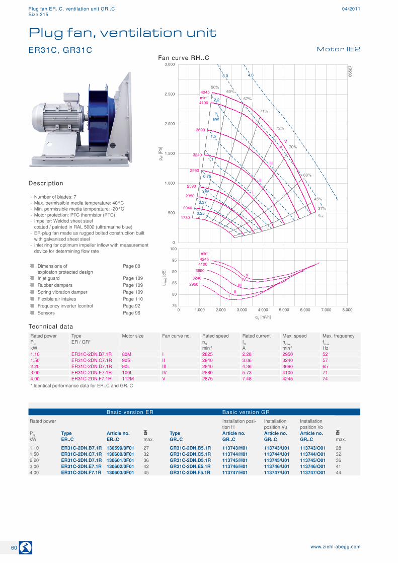
Technical dataRated power Type Motor size Fan curve no. Rated speed Rated current Max. speed Max. frequencyPN ER / GR* nN IN nmax fmaxkW min-1 A min-1 Hz1.10 ER31C-2DN.B7.1R 80M I 2825 2.28 2950 521.50 ER31C-2DN.C7.1R 90S II 2840 3.06 3240 572.20 ER31C-2DN.D7.1R 90L III 2840 4.36 3690 653.00 ER31C-2DN.E7.1R 100L IV 2880 5.73 4100 714.00 ER31C-2DN.F7.1R 112M V 2875 7.48 4245 74* Identical performance data for ER..C and GR..C
Basic version ER Basic version GR
Rated power Installation posi-tion H
Installation position Vu
Installation position Vo
PN Type Article no. Type Article no. Article no. Article no. kW ER..C ER..C max. GR..C GR..C GR..C GR..C max.
1.10 ER31C-2DN.B7.1R 130599/0F01 27 GR31C-2DN.B5.1R 113743/H01 113743/U01 113743/O01 281.50 ER31C-2DN.C7.1R 130600/0F01 32 GR31C-2DN.C5.1R 113744/H01 113744/U01 113744/O01 322.20 ER31C-2DN.D7.1R 130601/0F01 36 GR31C-2DN.D5.1R 113745/H01 113745/U01 113745/O01 363.00 ER31C-2DN.E7.1R 130602/0F01 42 GR31C-2DN.E5.1R 113746/H01 113746/U01 113746/O01 414.00 ER31C-2DN.F7.1R 130603/0F01 45 GR31C-2DN.F5.1R 113747/H01 113747/U01 113747/O01 44
Dimensions of explosion protected design
Page 88
Inlet guard Page 109Rubber dampers Page 109Spring vibration damper Page 109Flexible air intakes Page 110Frequency inverter Icontrol Page 92Sensors Page 96
ER31C, GR31C Motor IE2
Plug fan, ventilation unit
Description
- Number of blades: 7 - Max. permissible media temperature: 40°C - Min. permissible media temperature: -20°C - Motor protection: PTC thermistor (PTC) - Impeller: Welded sheet steel coated / painted in RAL 5002 (ultramarine blue)
- ER-plug fan made as rugged bolted construction built with galvanised sheet steel
- Inlet ring for optimum impeller inflow with measurement device for determining flow rate
Fan curve RH..C
60 www.ziehl-abegg.com
Plug fan ER..C, ventilation unit GR..C 04/2011Size 315

Dimensions in mm
Plug fan ER in installation position H
L-K
L-52
68-4
11Ø
360T
T1T7
T3 (T5)
415
215
400300
12
T4 (T6)
Rated power Type T T1 T3 T4 T5 T6 T7 Spring vibration
damperRubber dampers
PN
kW mm mm mm mm mm mm mm1.10 ER31C-2DN.B7.1R 460 475 360 70 316 71 194 MSN 4 30x30 / 401.50 ER31C-2DN.C7.1R 570 500 414 63 372 65 194 MSN 4 30x30 / 552.20 ER31C-2DN.D7.1R 570 525 412 79 350 93 194 MSN 5 30x30 / 553.00 ER31C-2DN.E7.1R 570 563 460 75 452 63 194 MSN 5 40x30 / 554.00 ER31C-2DN.F7.1R 570 612 434 97 472 63 194 MSN 5 40x30 / 55T5 and T6 apply to attachment of Ziehl-Abegg intake flanges.
Ventilation unit GR in installation position H Ventilation unit GR in installation position Vu/Vo
L-AL-3173-3174-4
450
410
375
Vu Vo
L-AL-3172-4
470434
375
407
11Ø
H1
242
15
H1
229,5 15
H1229,5
15
M6
Rated power Type Installation position H Installation position Vu
Installation position Vo
PN H1 H1 H1kW mm mm mm1.10 GR31C-2DN.B5.1R 463 475 4631.50 GR31C-2DN.C5.1R 488 500 4882.20 GR31C-2DN.D5.1R 513 525 5133.00 GR31C-2DN.E5.1R 551 563 5514.00 GR31C-2DN.F5.1R 600 612 600
61www.ziehl-abegg.com
RH
..C
pro
RH
..C
Ser
ies
E
R /
GR
ER
..C
pro
GR
..C
pro
Ex-
Des
ign
Sys
tem
C
ompo
nent
sA
ppen
dix
Info
rmat
ion
ER
..C
GR
..C
Plug fan ER..C, ventilation unit GR..C04/2011Size 315
1285
70
75
80
85
90
95
100
L WA
5 [d
B]
0 1.000 2.000 3.000 4.000 5.000 6.000 7.000 8.000 9.000 10.000
qV [m³/h]
2550
3030
3700 min-1
3350
2400
I II
III IV
V
0
500
1.000
1.500
2.000
2.500
3.000
p sF [P
a]
3,0 PL
kW
III
III
IV
2120
2400
2550
3030
3765
min-1
50% 60%
71%
67%
67%
58%
45%
37%
72%
71%
3350
1,1
0,75
0,55
0,37
0,12 1440
1660
4,0
5,5
1,5
2,2
3700
1910
V
ηfaL
8673
0
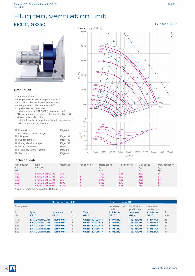
Technical dataRated power Type Motor size Fan curve no. Rated speed Rated current Max. speed Max. frequencyPN ER / GR* nN IN nmax fmaxkW min-1 A min-1 Hz1.10 ER35C-4DN.C7.1R 90S I 1400 2.46 2400 861.50 ER35C-4DN.D7.1R 90L II 1400 3.22 2550 912.20 ER35C-2DN.D7.1R 90L III 2840 4.36 3030 533.00 ER35C-2DN.E7.1R 100L IV 2880 5.73 3350 584.00 ER35C-2DN.F7.1R 112M V 2875 7.48 3700 64* Identical performance data for ER..C and GR..C
Basic version ER Basic version GR
Rated power Installation posi-tion H
Installation position Vu
Installation position Vo
PN Type Article no. Type Article no. Article no. Article no. kW ER..C ER..C max. GR..C GR..C GR..C GR..C max.
1.10 ER35C-4DN.C7.1R 131399/0F01 36 GR35C-4DN.C5.1R 113748/H01 113748/U01 113748/O01 361.50 ER35C-4DN.D7.1R 130595/0F01 39 GR35C-4DN.D5.1R 113749/H01 113749/U01 113749/O01 382.20 ER35C-2DN.D7.1R 130596/0F01 39 GR35C-2DN.D5.1R 113750/H01 113750/U01 113750/O01 393.00 ER35C-2DN.E7.1R 130597/0F01 46 GR35C-2DN.E5.1R 113751/H01 113751/U01 113751/O01 444.00 ER35C-2DN.F7.1R 130598/0F01 49 GR35C-2DN.F5.1R 113752/H01 113752/U01 113752/O01 47
Dimensions of explosion protected design
Page 88
Inlet guard Page 109Rubber dampers Page 109Spring vibration damper Page 109Flexible air intakes Page 110Frequency inverter Icontrol Page 92Sensors Page 96
ER35C, GR35C Motor IE2
Plug fan, ventilation unit
Description
- Number of blades: 7 - Max. permissible media temperature: 40°C - Min. permissible media temperature: -20°C - Motor protection: PTC thermistor (PTC) - Impeller: Welded sheet steel coated / painted in RAL 5002 (ultramarine blue)
- ER-plug fan made as rugged bolted construction built with galvanised sheet steel
- Inlet ring for optimum impeller inflow with measurement device for determining flow rate
Fan curve RH..C
62 www.ziehl-abegg.com
Plug fan ER..C, ventilation unit GR..C 04/2011Size 355
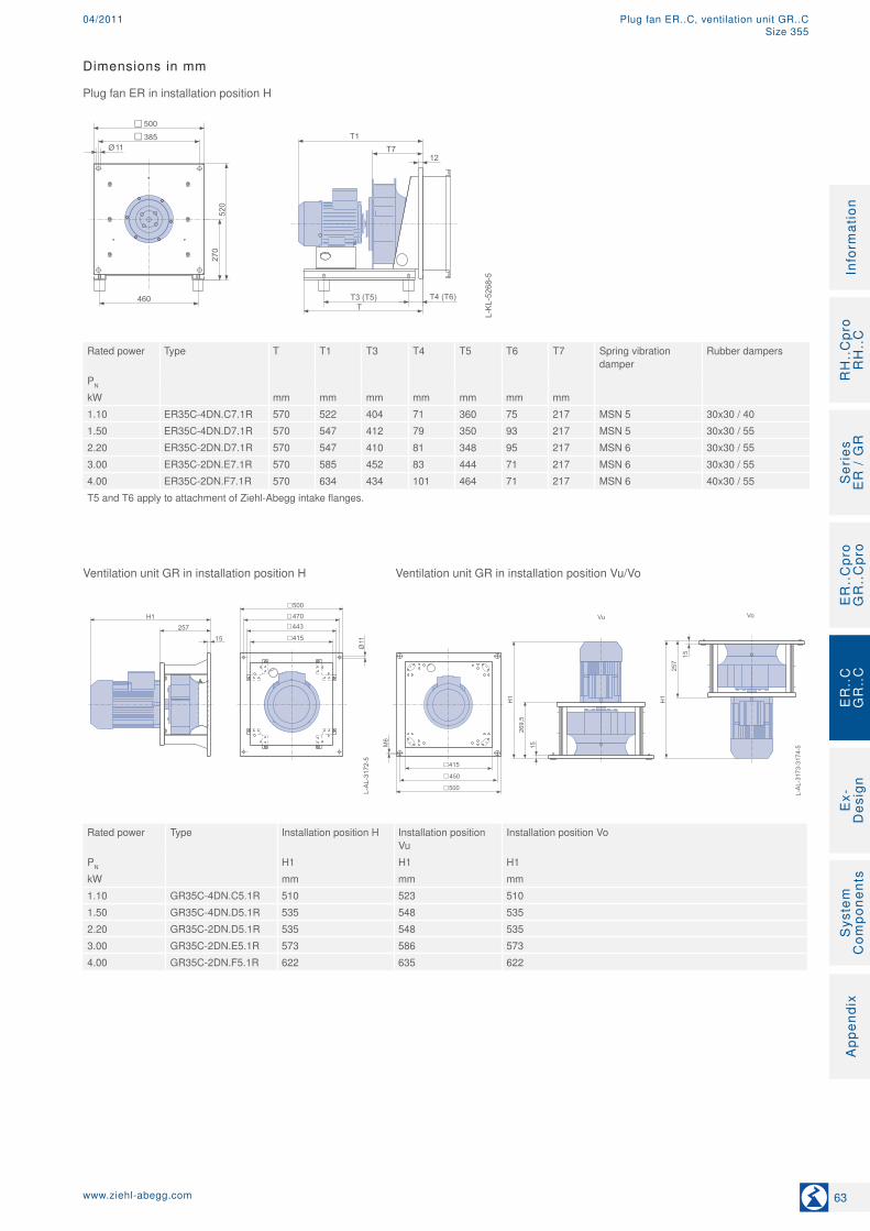
Dimensions in mm
Plug fan ER in installation position H
L-K
L-52
68-5
11Ø
460T
T1T7
T3 (T5)
520
270
500385
12
T4 (T6)
Rated power Type T T1 T3 T4 T5 T6 T7 Spring vibration
damperRubber dampers
PN
kW mm mm mm mm mm mm mm1.10 ER35C-4DN.C7.1R 570 522 404 71 360 75 217 MSN 5 30x30 / 401.50 ER35C-4DN.D7.1R 570 547 412 79 350 93 217 MSN 5 30x30 / 552.20 ER35C-2DN.D7.1R 570 547 410 81 348 95 217 MSN 6 30x30 / 553.00 ER35C-2DN.E7.1R 570 585 452 83 444 71 217 MSN 6 30x30 / 554.00 ER35C-2DN.F7.1R 570 634 434 101 464 71 217 MSN 6 40x30 / 55T5 and T6 apply to attachment of Ziehl-Abegg intake flanges.
Ventilation unit GR in installation position H Ventilation unit GR in installation position Vu/Vo
L-AL-3173-3174-5
500
450
415
Vu Vo
L-AL-3172-5
500470
415
443
11Ø
H1
269,5
15
H1
257
15
H1257
15
M6
Rated power Type Installation position H Installation position Vu
Installation position Vo
PN H1 H1 H1kW mm mm mm1.10 GR35C-4DN.C5.1R 510 523 5101.50 GR35C-4DN.D5.1R 535 548 5352.20 GR35C-2DN.D5.1R 535 548 5353.00 GR35C-2DN.E5.1R 573 586 5734.00 GR35C-2DN.F5.1R 622 635 622
63www.ziehl-abegg.com
RH
..C
pro
RH
..C
Ser
ies
E
R /
GR
ER
..C
pro
GR
..C
pro
Ex-
Des
ign
Sys
tem
C
ompo
nent
sA
ppen
dix
Info
rmat
ion
ER
..C
GR
..C
Plug fan ER..C, ventilation unit GR..C04/2011Size 355
0
500
1.000
1.500
2.000
2.500
3.000
p sF [P
a]
1,5
2,2
PL
kW
I
II
III
IV
1580
2205
2510
2650
3340
min-1
50% 62%
73%
70%
58%
45%
37%
72%
68%
3050
1,1
0,75
0,55
0,37
0,25
1755
1990
V
3,0
1350
4,0
5,5
73%
1180
VI
70
75
80
85
90
95
100
L WA
5 [d
B]
0 2.000 4.000 6.000 8.000 10.000 12.000
qV [m³/h]
2205
2510
3340
min-1 2650
3050
I
II III
IV
V
1990
VI
ηfaL
8554
4
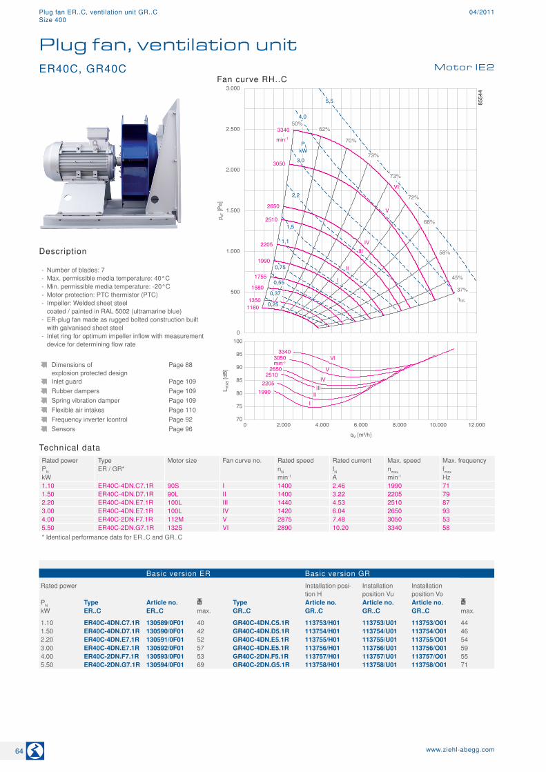
Technical dataRated power Type Motor size Fan curve no. Rated speed Rated current Max. speed Max. frequencyPN ER / GR* nN IN nmax fmaxkW min-1 A min-1 Hz1.10 ER40C-4DN.C7.1R 90S I 1400 2.46 1990 711.50 ER40C-4DN.D7.1R 90L II 1400 3.22 2205 792.20 ER40C-4DN.E7.1R 100L III 1440 4.53 2510 873.00 ER40C-4DN.E7.1R 100L IV 1420 6.04 2650 934.00 ER40C-2DN.F7.1R 112M V 2875 7.48 3050 535.50 ER40C-2DN.G7.1R 132S VI 2890 10.20 3340 58* Identical performance data for ER..C and GR..C
Basic version ER Basic version GR
Rated power Installation posi-tion H
Installation position Vu
Installation position Vo
PN Type Article no. Type Article no. Article no. Article no. kW ER..C ER..C max. GR..C GR..C GR..C GR..C max.
1.10 ER40C-4DN.C7.1R 130589/0F01 40 GR40C-4DN.C5.1R 113753/H01 113753/U01 113753/O01 441.50 ER40C-4DN.D7.1R 130590/0F01 42 GR40C-4DN.D5.1R 113754/H01 113754/U01 113754/O01 462.20 ER40C-4DN.E7.1R 130591/0F01 52 GR40C-4DN.E5.1R 113755/H01 113755/U01 113755/O01 543.00 ER40C-4DN.E7.1R 130592/0F01 57 GR40C-4DN.E5.1R 113756/H01 113756/U01 113756/O01 594.00 ER40C-2DN.F7.1R 130593/0F01 53 GR40C-2DN.F5.1R 113757/H01 113757/U01 113757/O01 555.50 ER40C-2DN.G7.1R 130594/0F01 69 GR40C-2DN.G5.1R 113758/H01 113758/U01 113758/O01 71
Dimensions of explosion protected design
Page 88
Inlet guard Page 109Rubber dampers Page 109Spring vibration damper Page 109Flexible air intakes Page 110Frequency inverter Icontrol Page 92Sensors Page 96
ER40C, GR40C Motor IE2
Plug fan, ventilation unit
Description
- Number of blades: 7 - Max. permissible media temperature: 40°C - Min. permissible media temperature: -20°C - Motor protection: PTC thermistor (PTC) - Impeller: Welded sheet steel coated / painted in RAL 5002 (ultramarine blue)
- ER-plug fan made as rugged bolted construction built with galvanised sheet steel
- Inlet ring for optimum impeller inflow with measurement device for determining flow rate
Fan curve RH..C
64 www.ziehl-abegg.com
Plug fan ER..C, ventilation unit GR..C 04/2011Size 400
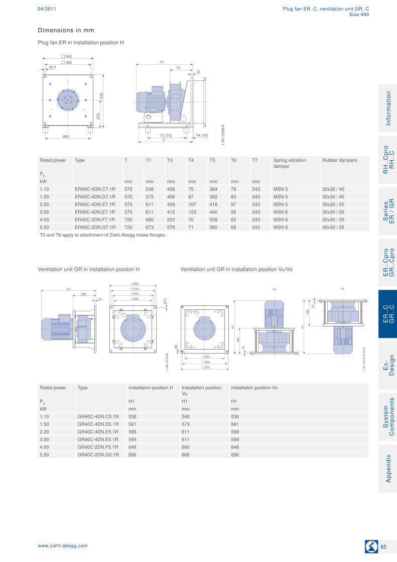
Dimensions in mm
Plug fan ER in installation position H
L-K
L-52
68-6
11Ø
460T
T1T7
T3 (T5)
520
270
500385
12
T4 (T6)
Rated power Type T T1 T3 T4 T5 T6 T7 Spring vibration
damperRubber dampers
PN
kW mm mm mm mm mm mm mm1.10 ER40C-4DN.C7.1R 570 548 406 75 364 79 243 MSN 5 30x30 / 401.50 ER40C-4DN.D7.1R 570 573 408 87 382 83 243 MSN 5 30x30 / 402.20 ER40C-4DN.E7.1R 570 611 428 107 418 97 243 MSN 5 30x30 / 553.00 ER40C-4DN.E7.1R 570 611 412 123 440 95 243 MSN 6 30x30 / 554.00 ER40C-2DN.F7.1R 720 660 520 70 508 62 243 MSN 6 30x30 / 555.50 ER40C-2DN.G7.1R 720 673 578 71 560 68 243 MSN 6 40x30 / 55T5 and T6 apply to attachment of Ziehl-Abegg intake flanges.
Ventilation unit GR in installation position H Ventilation unit GR in installation position Vu/Vo
L-AL-3173-3174-6
550
500
460
Vu Vo
L-AL-3172-6
550519
460
493
11Ø
H1
294
15
H1
282
15
H1282
15
M6
Rated power Type Installation position H Installation position Vu
Installation position Vo
PN H1 H1 H1kW mm mm mm1.10 GR40C-4DN.C5.1R 536 548 5361.50 GR40C-4DN.D5.1R 561 573 5612.20 GR40C-4DN.E5.1R 599 611 5993.00 GR40C-4DN.E5.1R 599 611 5994.00 GR40C-2DN.F5.1R 648 660 6485.50 GR40C-2DN.G5.1R 656 668 656
65www.ziehl-abegg.com
RH
..C
pro
RH
..C
Ser
ies
E
R /
GR
ER
..C
pro
GR
..C
pro
Ex-
Des
ign
Sys
tem
C
ompo
nent
sA
ppen
dix
Info
rmat
ion
ER
..C
GR
..C
Plug fan ER..C, ventilation unit GR..C04/2011Size 400
1285
70
75
80
85
90
95
100
L WA
5 [d
B]
0 2.000 4.000 6.000 8.000 10.000 12.000 14.000 16.000
qV [m³/h]
2255 2490
2970 min-1
2700
2035 1820
1640 I
II
IIIIVV
VI
VII
0
500
1.000
1.500
2.000
2.500
3.000
p sF [P
a]
1,5
2,2
PL
kW
I
II
III
IV 1820
2035
2255
2490
2970
min-1
50% 60%
72%
68%
67%
58%
45%
37%
73%
72%
2700
1,1
0,75
0,55
0,25
1410
1640
950
3,0
4,0
5,5
1260
V
VI
7,5
VII
ηfaL
8554
3
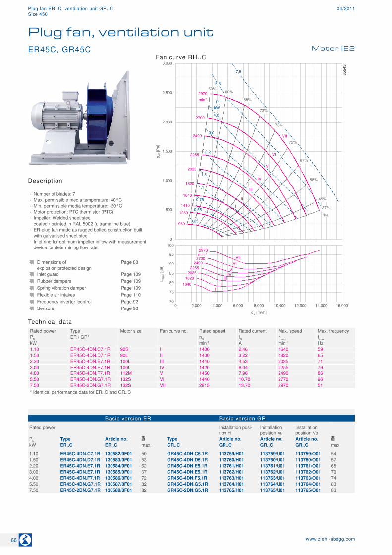
Technical dataRated power Type Motor size Fan curve no. Rated speed Rated current Max. speed Max. frequencyPN ER / GR* nN IN nmax fmaxkW min-1 A min-1 Hz1.10 ER45C-4DN.C7.1R 90S I 1400 2.46 1640 591.50 ER45C-4DN.D7.1R 90L II 1400 3.22 1820 652.20 ER45C-4DN.E7.1R 100L III 1440 4.53 2035 713.00 ER45C-4DN.E7.1R 100L IV 1420 6.04 2255 794.00 ER45C-4DN.F7.1R 112M V 1450 7.96 2490 865.50 ER45C-4DN.G7.1R 132S VI 1440 10.70 2770 967.50 ER45C-2DN.G7.1R 132S VII 2915 13.70 2970 51* Identical performance data for ER..C and GR..C
Basic version ER Basic version GR
Rated power Installation posi-tion H
Installation position Vu
Installation position Vo
PN Type Article no. Type Article no. Article no. Article no. kW ER..C ER..C max. GR..C GR..C GR..C GR..C max.
1.10 ER45C-4DN.C7.1R 130582/0F01 50 GR45C-4DN.C5.1R 113759/H01 113759/U01 113759/O01 541.50 ER45C-4DN.D7.1R 130583/0F01 53 GR45C-4DN.D5.1R 113760/H01 113760/U01 113760/O01 572.20 ER45C-4DN.E7.1R 130584/0F01 62 GR45C-4DN.E5.1R 113761/H01 113761/U01 113761/O01 653.00 ER45C-4DN.E7.1R 130585/0F01 67 GR45C-4DN.E5.1R 113762/H01 113762/U01 113762/O01 704.00 ER45C-4DN.F7.1R 130586/0F01 72 GR45C-4DN.F5.1R 113763/H01 113763/U01 113763/O01 745.50 ER45C-4DN.G7.1R 130587/0F01 82 GR45C-4DN.G5.1R 113764/H01 113764/U01 113764/O01 837.50 ER45C-2DN.G7.1R 130588/0F01 82 GR45C-2DN.G5.1R 113765/H01 113765/U01 113765/O01 83
Dimensions of explosion protected design
Page 88
Inlet guard Page 109Rubber dampers Page 109Spring vibration damper Page 109Flexible air intakes Page 110Frequency inverter Icontrol Page 92Sensors Page 96
ER45C, GR45C Motor IE2
Plug fan, ventilation unit
Description
- Number of blades: 7 - Max. permissible media temperature: 40°C - Min. permissible media temperature: -20°C - Motor protection: PTC thermistor (PTC) - Impeller: Welded sheet steel coated / painted in RAL 5002 (ultramarine blue)
- ER-plug fan made as rugged bolted construction built with galvanised sheet steel
- Inlet ring for optimum impeller inflow with measurement device for determining flow rate
Fan curve RH..C
66 www.ziehl-abegg.com
Plug fan ER..C, ventilation unit GR..C 04/2011Size 450

Dimensions in mm
Plug fan ER in installation position H
L-K
L-23
95-2
-1
560T
T1T7
T3 (T5)
650
335
630
12
T4 (T6)
465
11Ø
Rated power Type T T1 T3 T4 T5 T6 T7 Spring vibration
damperRubber dampers
PN
kW mm mm mm mm mm mm mm1.10 ER45C-4DN.C7.1R 570 582 414 75 350 92 271 MSN 5 30x30 / 401.50 ER45C-4DN.D7.1R 570 607 404 91 394 81 271 MSN 5 30x30 / 402.20 ER45C-4DN.E7.1R 570 645 424 111 422 98 271 MSN 6 30x30 / 553.00 ER45C-4DN.E7.1R 570 645 408 127 434 101 271 MSN 6 30x30 / 554.00 ER45C-4DN.F7.1R 720 694 572 58 496 84 271 MSN 6 30x30 / 555.50 ER45C-4DN.G7.1R 720 702 596 74 576 72 271 MSN 6 40x30 / 557.50 ER45C-2DN.G7.1R 720 702 616 64 588 66 271 MSN 7 40x30 / 55T5 and T6 apply to attachment of Ziehl-Abegg intake flanges.
Ventilation unit GR in installation position H Ventilation unit GR in installation position Vu/Vo
L-AL-3173-3174-7
600
550
516
Vu Vo
L-AL-3172-7
630580
516
555
11Ø
H1
327,5
15
H1
315,5 15
H1315,5
15
M6
Rated power Type Installation position H Installation position Vu
Installation position Vo
PN H1 H1 H1kW mm mm mm1.10 GR45C-4DN.C5.1R 570 582 5701.50 GR45C-4DN.D5.1R 595 607 5952.20 GR45C-4DN.E5.1R 633 645 6333.00 GR45C-4DN.E5.1R 633 645 6334.00 GR45C-4DN.F5.1R 682 694 6825.50 GR45C-4DN.G5.1R 690 702 6907.50 GR45C-2DN.G5.1R 690 702 690
67www.ziehl-abegg.com
RH
..C
pro
RH
..C
Ser
ies
E
R /
GR
ER
..C
pro
GR
..C
pro
Ex-
Des
ign
Sys
tem
C
ompo
nent
sA
ppen
dix
Info
rmat
ion
ER
..C
GR
..C
Plug fan ER..C, ventilation unit GR..C04/2011Size 450

1285
75
80
85
90
95
100
L WA
5 [d
B]
0 5.000 10.000 15.000 20.000
qV [m³/h]
2040
2270
2675 min-1
2520
1855
1675
1470
I
II III
IV
VVI
VII
0
500
1.000
1.500
2.000
2.500
3.000
p sF [P
a]
2,2
PL
kW
I
II
III
IV
1855
2040
2270
2520
min-1
50% 60%
73%
69%
69%
60%
45%
37%
73%
73%
2675
1,5
0,75
0,37
1470
1675
1310
3,0
4,0
1150
V
VI
7,5
VII
11,0
5,5
1,1
890
ηfaL
8553
0
Technical dataRated power Type Motor size Fan curve no. Rated speed Rated current Max. speed Max. frequencyPN ER / GR* nN IN nmax fmaxkW min-1 A min-1 Hz1.50 ER50C-4DN.D7.1R 90L I 1400 3.22 1470 532.20 ER50C-4DN.E7.1R 100L II 1440 4.53 1675 583.00 ER50C-4DN.E7.1R 100L III 1420 6.04 1855 654.00 ER50C-4DN.F7.1R 112M IV 1450 7.96 2040 705.50 ER50C-4DN.G7.1R 132S V 1440 10.70 2270 797.50 ER50C-4DN.H7.1R 132M VI 1440 14.30 2520 8811.00 ER50C-4DN.I7.1R 160M VII 1460 20.70 2675 92* Identical performance data for ER..C and GR..C
Basic version ER Basic version GR
Rated power Installation posi-tion H
Installation position Vu
Installation position Vo
PN Type Article no. Type Article no. Article no. Article no. kW ER..C ER..C max. GR..C GR..C GR..C GR..C max.
1.50 ER50C-4DN.D7.1R 130575/0F01 59 GR50C-4DN.D5.1R 113766/H01 113766/U01 113766/O01 712.20 ER50C-4DN.E7.1R 130576/0F01 68 GR50C-4DN.E5.1R 113767/H01 113767/U01 113767/O01 793.00 ER50C-4DN.E7.1R 130577/0F01 73 GR50C-4DN.E5.1R 113768/H01 113768/U01 113768/O01 844.00 ER50C-4DN.F7.1R 130578/0F01 77 GR50C-4DN.F5.1R 113769/H01 113769/U01 113769/O01 885.50 ER50C-4DN.G7.1R 130579/0F01 88 GR50C-4DN.G5.1R 113770/H01 113770/U01 113770/O01 977.50 ER50C-4DN.H7.1R 130580/0F01 98 GR50C-4DN.H5.1R 113771/H01 113771/U01 113771/O01 10811.00 ER50C-4DN.I7.1R 130581/0F01 168 GR50C-4DN.I5.1R 113772/H01 113772/U01 113772/O01 172
Dimensions of explosion protected design
Page 88
Inlet guard Page 109Rubber dampers Page 109Spring vibration damper Page 109Flexible air intakes Page 110Frequency inverter Icontrol Page 92Sensors Page 96
ER50C, GR50C Motor IE2
Plug fan, ventilation unit
Description
- Number of blades: 7 - Max. permissible media temperature: 40°C - Min. permissible media temperature: -20°C - Motor protection: PTC thermistor (PTC) - Impeller: Welded sheet steel coated / painted in RAL 5002 (ultramarine blue)
- ER-plug fan made as rugged bolted construction built with galvanised sheet steel
- Inlet ring for optimum impeller inflow with measurement device for determining flow rate
Fan curve RH..C
68 www.ziehl-abegg.com
Plug fan ER..C, ventilation unit GR..C 04/2011Size 500

Dimensions in mm
Plug fan ER in installation position H
L-K
L-23
95-2
-2
560T
T1T7
T3 (T5)
650
335
630
20
T4 (T6)
465
11Ø
Rated power Type T T1 T3 T4 T5 T6 T7 Spring vibration
damperRubber dampers
PN
kW mm mm mm mm mm mm mm1.50 ER50C-4DN.D7.1R 728 648 508 67 438 87 313 MSN 6 30x30 / 402.20 ER50C-4DN.E7.1R 728 686 582 59 454 109 313 MSN 6 30x30 / 403.00 ER50C-4DN.E7.1R 728 686 600 59 480 105 313 MSN 6 30x30 / 404.00 ER50C-4DN.F7.1R 728 735 602 68 514 99 313 MSN 6 30x30 / 555.50 ER50C-4DN.G7.1R 728 743 594 99 598 85 313 MSN 7 30x30 / 557.50 ER50C-4DN.H7.1R 728 781 546 147 564 126 313 MSN 7 40x30 / 5511.00 ER50C-4DN.I7.1R 888 853 718 135 686 144 313 MSN 7 40x30 / 55T5 and T6 apply to attachment of Ziehl-Abegg intake flanges.
Ventilation unit GR in installation position H Ventilation unit GR in installation position Vu/Vo
L-AL-3173-3174-8
670
615
580
Vu Vo
L-AL-3172-8
670635
580
614
11Ø
H1
375
25
H1
353
25
H1353
25
M8
Rated power Type Installation position H Installation position Vu
Installation position Vo
PN H1 H1 H1kW mm mm mm1.50 GR50C-4DN.D5.1R 628 650 6282.20 GR50C-4DN.E5.1R 666 688 6663.00 GR50C-4DN.E5.1R 666 688 6664.00 GR50C-4DN.F5.1R 715 737 7155.50 GR50C-4DN.G5.1R 723 745 7237.50 GR50C-4DN.H5.1R 761 783 76111.00 GR50C-4DN.I5.1R 833 855 833
69www.ziehl-abegg.com
RH
..C
pro
RH
..C
Ser
ies
E
R /
GR
ER
..C
pro
GR
..C
pro
Ex-
Des
ign
Sys
tem
C
ompo
nent
sA
ppen
dix
Info
rmat
ion
ER
..C
GR
..C
Plug fan ER..C, ventilation unit GR..C04/2011Size 500
1285
70
75
80
85
90
95
100
L WA
5 [d
B]
0 5.000 10.000 15.000 20.000 25.000
qV [m³/h]
1725
1920
2310 min-1
2115
1560 1405
1240 I
II
IIIIV
V
VIVII
0
500
1.000
1.500
2.000
2.500
3.000
p sF [P
a]
2,2
PL
kW
I
II
III
IV
1560
1725
1920
2115
min-1
50% 62%
73%
70%
69%
60%
45%
37%
73%
73%
2310
1,5
0,75
0,37
1120
1405
760
3,0
4,0
970
V
VI
7,5
VII
11,0
5,5
1,1 1240
ηfaL
8549
1
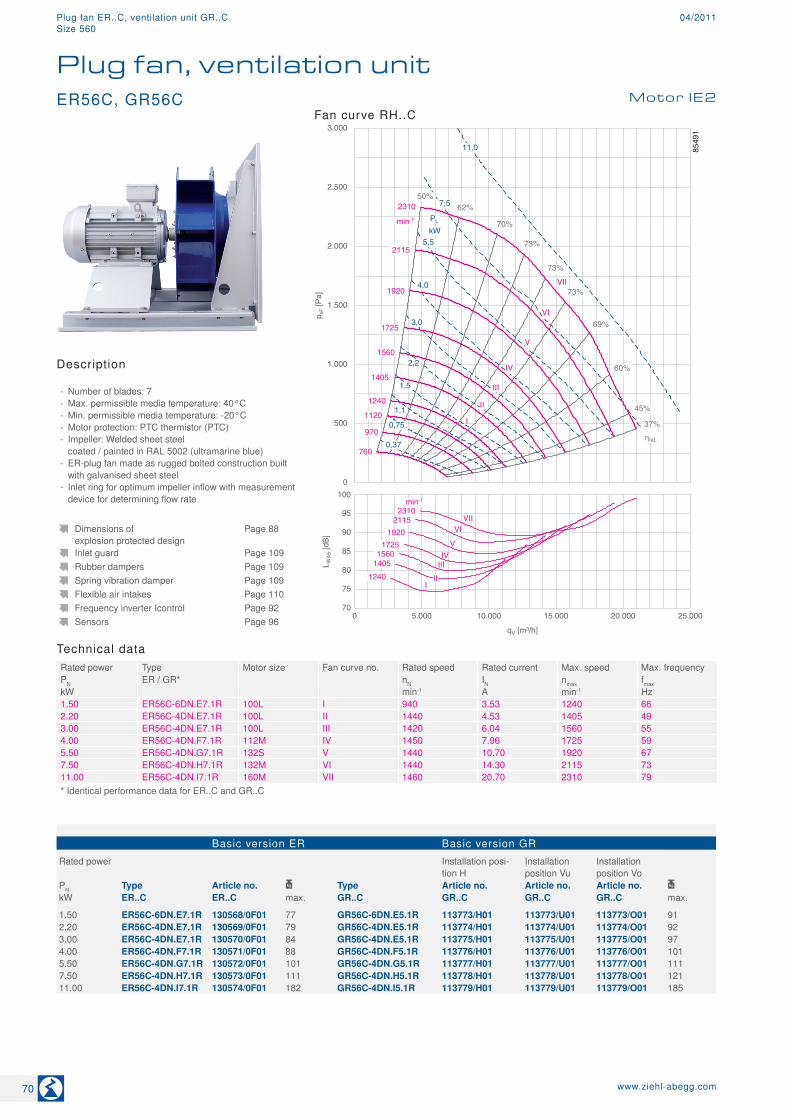
Technical dataRated power Type Motor size Fan curve no. Rated speed Rated current Max. speed Max. frequencyPN ER / GR* nN IN nmax fmaxkW min-1 A min-1 Hz1.50 ER56C-6DN.E7.1R 100L I 940 3.53 1240 662.20 ER56C-4DN.E7.1R 100L II 1440 4.53 1405 493.00 ER56C-4DN.E7.1R 100L III 1420 6.04 1560 554.00 ER56C-4DN.F7.1R 112M IV 1450 7.96 1725 595.50 ER56C-4DN.G7.1R 132S V 1440 10.70 1920 677.50 ER56C-4DN.H7.1R 132M VI 1440 14.30 2115 7311.00 ER56C-4DN.I7.1R 160M VII 1460 20.70 2310 79* Identical performance data for ER..C and GR..C
Basic version ER Basic version GR
Rated power Installation posi-tion H
Installation position Vu
Installation position Vo
PN Type Article no. Type Article no. Article no. Article no. kW ER..C ER..C max. GR..C GR..C GR..C GR..C max.
1.50 ER56C-6DN.E7.1R 130568/0F01 77 GR56C-6DN.E5.1R 113773/H01 113773/U01 113773/O01 912.20 ER56C-4DN.E7.1R 130569/0F01 79 GR56C-4DN.E5.1R 113774/H01 113774/U01 113774/O01 923.00 ER56C-4DN.E7.1R 130570/0F01 84 GR56C-4DN.E5.1R 113775/H01 113775/U01 113775/O01 974.00 ER56C-4DN.F7.1R 130571/0F01 88 GR56C-4DN.F5.1R 113776/H01 113776/U01 113776/O01 1015.50 ER56C-4DN.G7.1R 130572/0F01 101 GR56C-4DN.G5.1R 113777/H01 113777/U01 113777/O01 1117.50 ER56C-4DN.H7.1R 130573/0F01 111 GR56C-4DN.H5.1R 113778/H01 113778/U01 113778/O01 12111.00 ER56C-4DN.I7.1R 130574/0F01 182 GR56C-4DN.I5.1R 113779/H01 113779/U01 113779/O01 185
Dimensions of explosion protected design
Page 88
Inlet guard Page 109Rubber dampers Page 109Spring vibration damper Page 109Flexible air intakes Page 110Frequency inverter Icontrol Page 92Sensors Page 96
ER56C, GR56C Motor IE2
Plug fan, ventilation unit
Description
- Number of blades: 7 - Max. permissible media temperature: 40°C - Min. permissible media temperature: -20°C - Motor protection: PTC thermistor (PTC) - Impeller: Welded sheet steel coated / painted in RAL 5002 (ultramarine blue)
- ER-plug fan made as rugged bolted construction built with galvanised sheet steel
- Inlet ring for optimum impeller inflow with measurement device for determining flow rate
Fan curve RH..C
70 www.ziehl-abegg.com
Plug fan ER..C, ventilation unit GR..C 04/2011Size 560
Dimensions in mm
Plug fan ER in installation position H
L-K
L-23
95-2
-3
720T
T1T7
T3 (T5)
813
433
760
20
T4 (T6)
660
11Ø
Rated power Type T T1 T3 T4 T5 T6 T7 Spring vibration
damperRubber dampers
PN
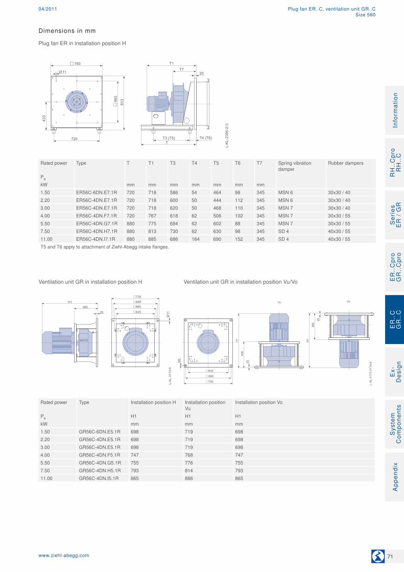
kW mm mm mm mm mm mm mm1.50 ER56C-6DN.E7.1R 720 718 586 54 464 98 345 MSN 6 30x30 / 402.20 ER56C-4DN.E7.1R 720 718 600 50 444 112 345 MSN 6 30x30 / 403.00 ER56C-4DN.E7.1R 720 718 620 50 468 110 345 MSN 7 30x30 / 404.00 ER56C-4DN.F7.1R 720 767 618 62 506 102 345 MSN 7 30x30 / 555.50 ER56C-4DN.G7.1R 880 775 684 62 602 88 345 MSN 7 30x30 / 557.50 ER56C-4DN.H7.1R 880 813 730 62 630 98 345 SD 4 40x30 / 5511.00 ER56C-4DN.I7.1R 880 885 686 164 690 152 345 SD 4 40x30 / 55T5 and T6 apply to attachment of Ziehl-Abegg intake flanges.
Ventilation unit GR in installation position H Ventilation unit GR in installation position Vu/Vo
L-AL-3173-3174-9
750
690
645
Vu Vo
L-AL-3172-9
730689
645
666
11Ø
H1
406
25
H1
385
25
H1385
25
M8
Rated power Type Installation position H Installation position Vu
Installation position Vo
PN H1 H1 H1kW mm mm mm1.50 GR56C-6DN.E5.1R 698 719 6982.20 GR56C-4DN.E5.1R 698 719 6983.00 GR56C-4DN.E5.1R 698 719 6984.00 GR56C-4DN.F5.1R 747 768 7475.50 GR56C-4DN.G5.1R 755 776 7557.50 GR56C-4DN.H5.1R 793 814 79311.00 GR56C-4DN.I5.1R 865 886 865
71www.ziehl-abegg.com
RH
..C
pro
RH
..C
Ser
ies
E
R /
GR
ER
..C
pro
GR
..C
pro
Ex-
Des
ign
Sys
tem
C
ompo
nent
sA
ppen
dix
Info
rmat
ion
ER
..C
GR
..C
Plug fan ER..C, ventilation unit GR..C04/2011Size 560
70
75
80
85
90
95
100
L WA
5 [d
B]
0 5.000 10.000 15.000 20.000 25.000 30.000
qV [m³/h]
1575 1740
2060 min-1
1980
1415 1290
1160
1020 I
II III
IV
V
VI VII
VIII
0
500
1.000
1.500
2.000
2.500
3.000
p sF [P
a]
2,2
PL
kW
I
II
III
IV
1415
1575
1740
1980 min-1
50% 60%
72%
68%
67%
58%
45%
37%
73%
72%
2060
1,5
0,75
0,37
1160
1290
800
3,0
4,0
1020
V
VI
7,5
VIII
11,0
5,5
15,0
630
VII
ηfaL
8553
1
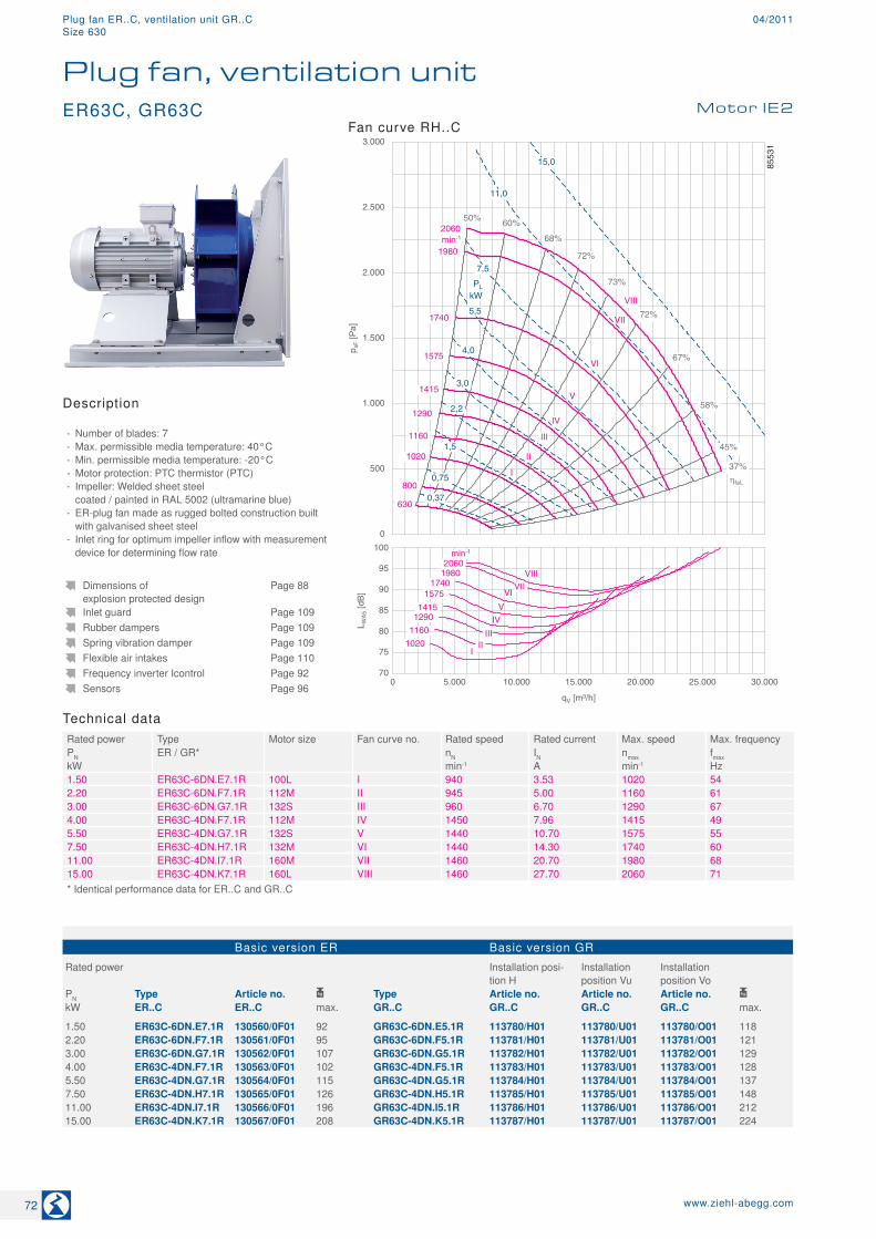
Technical dataRated power Type Motor size Fan curve no. Rated speed Rated current Max. speed Max. frequencyPN ER / GR* nN IN nmax fmaxkW min-1 A min-1 Hz1.50 ER63C-6DN.E7.1R 100L I 940 3.53 1020 542.20 ER63C-6DN.F7.1R 112M II 945 5.00 1160 613.00 ER63C-6DN.G7.1R 132S III 960 6.70 1290 674.00 ER63C-4DN.F7.1R 112M IV 1450 7.96 1415 495.50 ER63C-4DN.G7.1R 132S V 1440 10.70 1575 557.50 ER63C-4DN.H7.1R 132M VI 1440 14.30 1740 6011.00 ER63C-4DN.I7.1R 160M VII 1460 20.70 1980 6815.00 ER63C-4DN.K7.1R 160L VIII 1460 27.70 2060 71* Identical performance data for ER..C and GR..C
Basic version ER Basic version GR
Rated power Installation posi-tion H
Installation position Vu
Installation position Vo
PN Type Article no. Type Article no. Article no. Article no. kW ER..C ER..C max. GR..C GR..C GR..C GR..C max.
1.50 ER63C-6DN.E7.1R 130560/0F01 92 GR63C-6DN.E5.1R 113780/H01 113780/U01 113780/O01 1182.20 ER63C-6DN.F7.1R 130561/0F01 95 GR63C-6DN.F5.1R 113781/H01 113781/U01 113781/O01 1213.00 ER63C-6DN.G7.1R 130562/0F01 107 GR63C-6DN.G5.1R 113782/H01 113782/U01 113782/O01 1294.00 ER63C-4DN.F7.1R 130563/0F01 102 GR63C-4DN.F5.1R 113783/H01 113783/U01 113783/O01 1285.50 ER63C-4DN.G7.1R 130564/0F01 115 GR63C-4DN.G5.1R 113784/H01 113784/U01 113784/O01 1377.50 ER63C-4DN.H7.1R 130565/0F01 126 GR63C-4DN.H5.1R 113785/H01 113785/U01 113785/O01 14811.00 ER63C-4DN.I7.1R 130566/0F01 196 GR63C-4DN.I5.1R 113786/H01 113786/U01 113786/O01 21215.00 ER63C-4DN.K7.1R 130567/0F01 208 GR63C-4DN.K5.1R 113787/H01 113787/U01 113787/O01 224
Dimensions of explosion protected design
Page 88
Inlet guard Page 109Rubber dampers Page 109Spring vibration damper Page 109Flexible air intakes Page 110Frequency inverter Icontrol Page 92Sensors Page 96
Description
- Number of blades: 7 - Max. permissible media temperature: 40°C - Min. permissible media temperature: -20°C - Motor protection: PTC thermistor (PTC) - Impeller: Welded sheet steel coated / painted in RAL 5002 (ultramarine blue)
- ER-plug fan made as rugged bolted construction built with galvanised sheet steel
- Inlet ring for optimum impeller inflow with measurement device for determining flow rate
Fan curve RH..CER63C, GR63C Motor IE2
Plug fan, ventilation unit
72 www.ziehl-abegg.com
Plug fan ER..C, ventilation unit GR..C 04/2011Size 630
Ventilation unit GR in installation position H Ventilation unit GR in installation position Vu/Vo
L-AL-3173-3174-10
840
780
722
Vu Vo
L-AL-3172-10
840800
722
770
11Ø
H1
455,5
25
H1
434,5 25
H1434,5
25
M8
Rated power Type Installation position H Installation position Vu
Installation position Vo
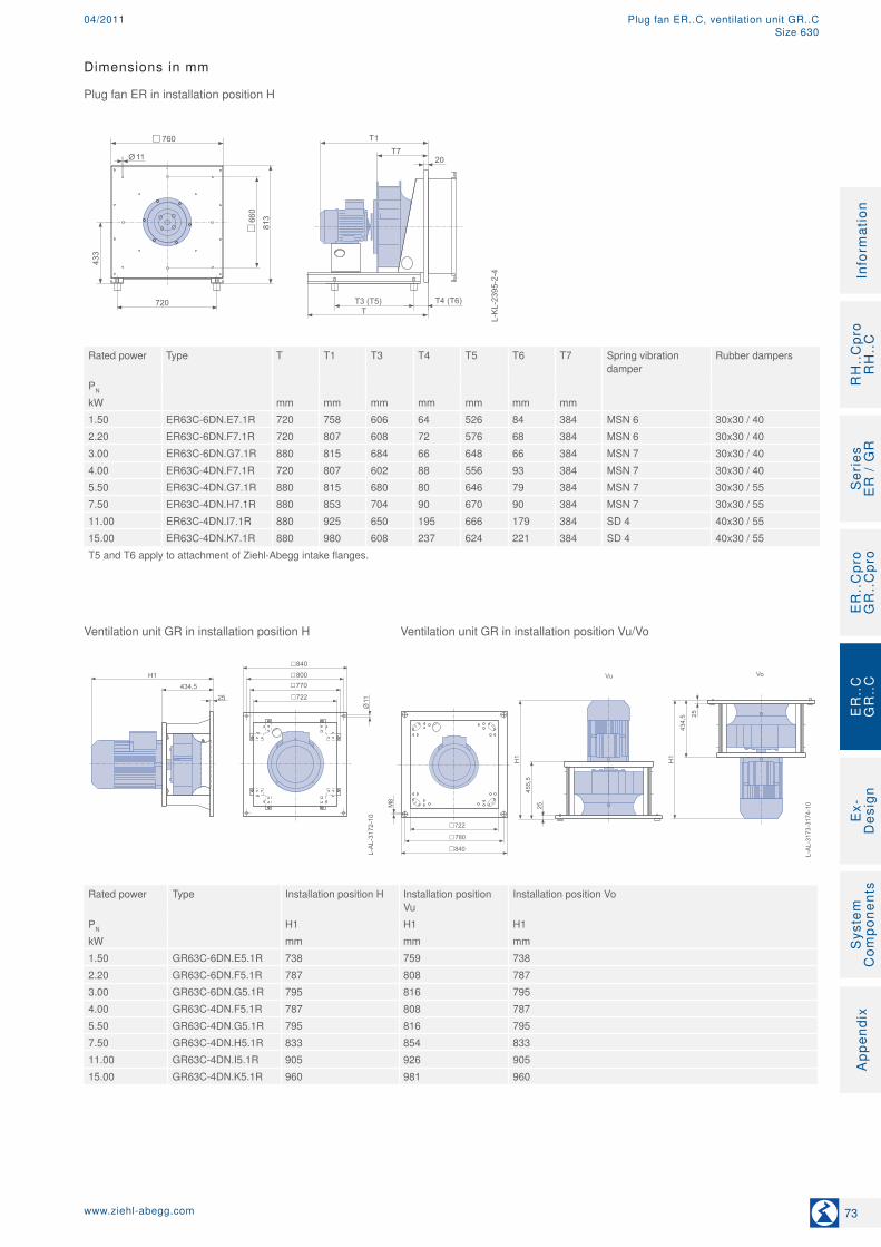
PN H1 H1 H1kW mm mm mm1.50 GR63C-6DN.E5.1R 738 759 7382.20 GR63C-6DN.F5.1R 787 808 7873.00 GR63C-6DN.G5.1R 795 816 7954.00 GR63C-4DN.F5.1R 787 808 7875.50 GR63C-4DN.G5.1R 795 816 7957.50 GR63C-4DN.H5.1R 833 854 83311.00 GR63C-4DN.I5.1R 905 926 90515.00 GR63C-4DN.K5.1R 960 981 960
Dimensions in mm
Plug fan ER in installation position H
L-K
L-23
95-2
-4
720T
T1T7
T3 (T5)
813
433
760
20
T4 (T6)
660
11Ø
Rated power Type T T1 T3 T4 T5 T6 T7 Spring vibration
damperRubber dampers
PN
kW mm mm mm mm mm mm mm1.50 ER63C-6DN.E7.1R 720 758 606 64 526 84 384 MSN 6 30x30 / 402.20 ER63C-6DN.F7.1R 720 807 608 72 576 68 384 MSN 6 30x30 / 403.00 ER63C-6DN.G7.1R 880 815 684 66 648 66 384 MSN 7 30x30 / 404.00 ER63C-4DN.F7.1R 720 807 602 88 556 93 384 MSN 7 30x30 / 405.50 ER63C-4DN.G7.1R 880 815 680 80 646 79 384 MSN 7 30x30 / 557.50 ER63C-4DN.H7.1R 880 853 704 90 670 90 384 MSN 7 30x30 / 5511.00 ER63C-4DN.I7.1R 880 925 650 195 666 179 384 SD 4 40x30 / 5515.00 ER63C-4DN.K7.1R 880 980 608 237 624 221 384 SD 4 40x30 / 55T5 and T6 apply to attachment of Ziehl-Abegg intake flanges.
73www.ziehl-abegg.com
RH
..C
pro
RH
..C
Ser
ies
E
R /
GR
ER
..C
pro
GR
..C
pro
Ex-
Des
ign
Sys
tem
C
ompo
nent
sA
ppen
dix
Info
rmat
ion
ER
..C
GR
..C
Plug fan ER..C, ventilation unit GR..C04/2011Size 630
70
75
80
85
90
95
100
105
L WA
5 [d
B]
0 5.000 10.000 15.000 20.000 25.000 30.000 35.000 40.000
qV [m³/h]
1425 1635
1840 min-1
1805
1285 1155
1050
945 I
II III
IV
V VI VII
VIII
0
500
1.000
1.500
2.000
2.500
3.000
p sF [P
a]
2,2
PL kW
I
II
III
IV
1285
1425
1635
1805 min-1
50% 60%
73%
69%
68%
58%
45%
37%
73%
73%
1840
1,1
0,55
1050
1155
750
3,0
4,0
945
V
VI
7,5 VIII
11,0
5,5
15,0
580
VII
18,5
ηfaL
8553
2
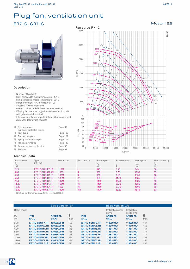
Technical dataRated power Type Motor size Fan curve no. Rated speed Rated current Max. speed Max. frequencyPN ER / GR* nN IN nmax fmaxkW min-1 A min-1 Hz2.20 ER71C-6DN.F7.1R 112M I 945 5.00 945 503.00 ER71C-6DN.G7.1R 132S II 960 6.70 1050 554.00 ER71C-6DN.H7.1R 132M III 960 8.10 1155 605.50 ER71C-6DN.H7.1R 132M IV 960 11.80 1285 677.50 ER71C-4DN.H7.1R 132M V 1440 14.30 1425 4911.00 ER71C-4DN.I7.1R 160M VI 1460 20.70 1635 5615.00 ER71C-4DN.K7.1R 160L VII 1460 27.70 1805 6218.50 ER71C-4DN.L7.1R 180M VIII 1470 33.60 1840 63* Identical performance data for ER..C and GR..C
Basic version ER Basic version GR
Rated power Installation positi-on Vu
Installation position Vo
PN Type Article no. Type Article no. Article no. kW ER..C ER..C max. GR..C GR..C GR..C max.
2.20 ER71C-6DN.F7.1R 130552/0F01 126 GR71C-6DN.F5.1R 113809/U01 113809/O01 1473.00 ER71C-6DN.G7.1R 130553/0F01 137 GR71C-6DN.G5.1R 113810/U01 113810/O01 1564.00 ER71C-6DN.H7.1R 130554/0F01 146 GR71C-6DN.H5.1R 113811/U01 113811/O01 1645.50 ER71C-6DN.H7.1R 130555/0F01 155 GR71C-6DN.H5.1R 113812/U01 113812/O01 1747.50 ER71C-4DN.H7.1R 130556/0F01 156 GR71C-4DN.H5.1R 113813/U01 113813/O01 17411.00 ER71C-4DN.I7.1R 130557/0F01 224 GR71C-4DN.I5.1R 113814/U01 113814/O01 23815.00 ER71C-4DN.K7.1R 130558/0F01 236 GR71C-4DN.K5.1R 113815/U01 113815/O01 25018.50 ER71C-4DN.L7.1R 130559/0F01 273 GR71C-4DN.L5.1R 113816/U01 113816/O01 285
Dimensions of explosion protected design
Page 88
Inlet guard Page 109Rubber dampers Page 109Spring vibration damper Page 109Flexible air intakes Page 110Frequency inverter Icontrol Page 92Sensors Page 96
Description
- Number of blades: 7 - Max. permissible media temperature: 40°C - Min. permissible media temperature: -20°C - Motor protection: PTC thermistor (PTC) - Impeller: Welded sheet steel coated / painted in RAL 5002 (ultramarine blue)
- ER-plug fan made as rugged bolted construction built with galvanised sheet steel
- Inlet ring for optimum impeller inflow with measurement device for determining flow rate
Fan curve RH..C
Plug fan, ventilation unitMotor IE2ER71C, GR71C
74 www.ziehl-abegg.com
Plug fan ER..C, ventilation unit GR..C 04/2011Size 710

Dimensions in mm
Plug fan ER in installation position H
L-K
L-23
95-2
-5
910T
T1T7
T3 (T5)
1023
543
960
25
T4 (T6)
750
11Ø
Rated power Type T T1 T3 T4 T5 T6 T7 Spring vibration
damperRubber dampers
PN
kW mm mm mm mm mm mm mm2.20 ER71C-6DN.F7.1R 885 858 636 84 608 82 435 MSN 7 40x40 / 403.00 ER71C-6DN.G7.1R 885 866 690 85 662 83 435 MSN 7 40x40 / 404.00 ER71C-6DN.H7.1R 885 904 708 94 680 92 435 SD 4 40x40 / 405.50 ER71C-6DN.H7.1R 885 904 740 90 710 90 435 SD 4 40x40 / 407.50 ER71C-4DN.H7.1R 885 904 712 105 686 102 435 SD 4 40x40 / 4011.00 ER71C-4DN.I7.1R 1045 976 756 169 722 173 435 SD 4 50x50 / 5515.00 ER71C-4DN.K7.1R 1045 1031 802 165 772 168 435 SD 5 50x50 / 5518.50 ER71C-4DN.L7.1R 1045 1101 836 174 858 152 435 SD 5 50x50 / 55T5 and T6 apply to attachment of Ziehl-Abegg intake flanges.
Ventilation unit GR in installation position Vu/Vo
L-KL-2520-2-1
Vu Vo
H1
511,5
25
H1
490,5 25
M8/M10
990
920
630
870
Rated power Type Installation position Vu Installation position Vo
PN H1 H1kW mm mm2.20 GR71C-6DN.F5.1R 854 8333.00 GR71C-6DN.G5.1R 862 8414.00 GR71C-6DN.H5.1R 900 8795.50 GR71C-6DN.H5.1R 900 8797.50 GR71C-4DN.H5.1R 900 87911.00 GR71C-4DN.I5.1R 972 95115.00 GR71C-4DN.K5.1R 1027 100618.50 GR71C-4DN.L5.1R 1057 1036
75www.ziehl-abegg.com
RH
..C
pro
RH
..C
Ser
ies
E
R /
GR
ER
..C
pro
GR
..C
pro
Ex-
Des
ign
Sys
tem
C
ompo
nent
sA
ppen
dix
Info
rmat
ion
ER
..C
GR
..C
Plug fan ER..C, ventilation unit GR..C04/2011Size 710
75
80
85
90
95
100
105
L WA
5 [d
B]
0 10.000 20.000 30.000 40.000 50.000
qV [m³/h]
1335 1485
1620 min-1
1595
1175
1060 960 I
II
III IV
V VI
VII
0
500
1.000
1.500
2.000
2.500
3.000
p sF [P
a]
2,2
PL
kW
I
II
III
IV 1175
1335
1485
1595
min-1
50% 60%
73%
68%
67%
58%
45%
37%
73%
73%
1620
1,1
0,55
960
1060
610
4,0
780
V
VI 7,5
11,0
5,5
15,0
480
VII
18,5
22,0
ηfaL
8553
3
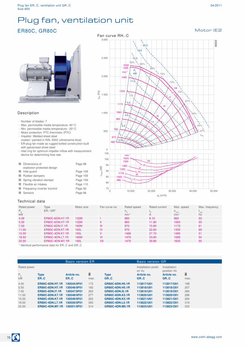
Technical dataRated power Type Motor size Fan curve no. Rated speed Rated current Max. speed Max. frequencyPN ER / GR* nN IN nmax fmaxkW min-1 A min-1 Hz4.00 ER80C-6DN.H7.1R 132M I 960 8.10 960 505.50 ER80C-6DN.H7.1R 132M II 960 11.80 1060 557.50 ER80C-6DN.I7.1R 160M III 970 15.80 1175 6111.00 ER80C-6DN.K7.1R 160L IV 970 22.60 1335 6915.00 ER80C-4DN.K7.1R 160L V 1460 27.70 1485 5118.50 ER80C-4DN.L7.1R 180M VI 1470 33.60 1595 5422.00 ER80C-4DN.M7.1R 180L VII 1470 39.80 1620 55* Identical performance data for ER..C and GR..C
Basic version ER Basic version GR
Rated power Installation positi-on Vu
Installation position Vo
PN Type Article no. Type Article no. Article no. kW ER..C ER..C max. GR..C GR..C GR..C max.
4.00 ER80C-6DN.H7.1R 130545/0F01 173 GR80C-6DN.H5.1R 113817/U01 113817/O01 1985.50 ER80C-6DN.H7.1R 130546/0F01 182 GR80C-6DN.H5.1R 113818/U01 113818/O01 2077.50 ER80C-6DN.I7.1R 130547/0F01 263 GR80C-6DN.I5.1R 113819/U01 113819/O01 28411.00 ER80C-6DN.K7.1R 130548/0F01 277 GR80C-6DN.K5.1R 113820/U01 113820/O01 29815.00 ER80C-4DN.K7.1R 130549/0F01 263 GR80C-4DN.K5.1R 113821/U01 113821/O01 28418.50 ER80C-4DN.L7.1R 130550/0F01 300 GR80C-4DN.L5.1R 113822/U01 113822/O01 31922.00 ER80C-4DN.M7.1R 130551/0F01 314 GR80C-4DN.M5.1R 113823/U01 113823/O01 333
Dimensions of explosion protected design
Page 88
Inlet guard Page 109Rubber dampers Page 109Spring vibration damper Page 109Flexible air intakes Page 110Frequency inverter Icontrol Page 92Sensors Page 96
Description
- Number of blades: 7 - Max. permissible media temperature: 40°C - Min. permissible media temperature: -20°C - Motor protection: PTC thermistor (PTC) - Impeller: Welded sheet steel coated / painted in RAL 5002 (ultramarine blue)
- ER-plug fan made as rugged bolted construction built with galvanised sheet steel
- Inlet ring for optimum impeller inflow with measurement device for determining flow rate
Fan curve RH..C
Plug fan, ventilation unitMotor IE2ER80C, GR80C
76 www.ziehl-abegg.com
Plug fan ER..C, ventilation unit GR..C 04/2011Size 800
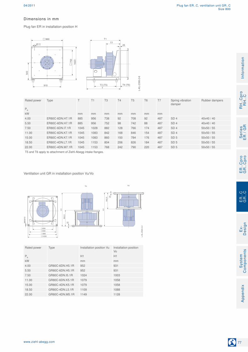
Dimensions in mm
Plug fan ER in installation position H
L-K
L-23
95-2
-6
910T
T1T7
T3 (T5)
1023
543
960
25
T4 (T6)
750
11Ø
Rated power Type T T1 T3 T4 T5 T6 T7 Spring vibration
damperRubber dampers
PN
kW mm mm mm mm mm mm mm4.00 ER80C-6DN.H7.1R 885 956 738 92 708 92 487 SD 4 40x40 / 405.50 ER80C-6DN.H7.1R 885 956 752 98 742 88 487 SD 4 40x40 / 407.50 ER80C-6DN.I7.1R 1045 1028 882 128 766 174 487 SD 4 50x50 / 5511.00 ER80C-6DN.K7.1R 1045 1083 842 168 846 154 487 SD 4 50x50 / 5515.00 ER80C-4DN.K7.1R 1045 1083 860 150 784 176 487 SD 5 50x50 / 5518.50 ER80C-4DN.L7.1R 1045 1153 804 206 826 184 487 SD 5 50x50 / 5522.00 ER80C-4DN.M7.1R 1045 1153 768 242 790 220 487 SD 5 50x50 / 55T5 and T6 apply to attachment of Ziehl-Abegg intake flanges.
Ventilation unit GR in installation position Vu/Vo
L-KL-2520-2-2
Vu Vo
H1
563,5
25
H1
542,5 25
M8/M10
1050
980
690
930
Rated power Type Installation position Vu Installation position Vo
PN H1 H1kW mm mm4.00 GR80C-6DN.H5.1R 952 9315.50 GR80C-6DN.H5.1R 952 9317.50 GR80C-6DN.I5.1R 1024 100311.00 GR80C-6DN.K5.1R 1079 105815.00 GR80C-4DN.K5.1R 1079 105818.50 GR80C-4DN.L5.1R 1109 108822.00 GR80C-4DN.M5.1R 1149 1128
77www.ziehl-abegg.com
RH
..C
pro
RH
..C
Ser
ies
E
R /
GR
ER
..C
pro
GR
..C
pro
Ex-
Des
ign
Sys
tem
C
ompo
nent
sA
ppen
dix
Info
rmat
ion
ER
..C
GR
..C
Plug fan ER..C, ventilation unit GR..C04/2011Size 800
80
85
90
95
100
105
L WA
5 [d
B]
0 10.000 20.000 30.000 40.000 50.000 60.000
qV [m³/h]
1090
1210
1380
min-1
1300
970 870
780
1475
I II
III
IV
V
VI VII
0
500
1.000
1.500
2.000
2.500
3.000
p sF [P
a]
3,0
PL
kW
I
II
III
IV 970
1090
1210
1380
min-1
50% 60%
73%
68%
67%
58%
45%
37%
73%
73%
1475
780
870
550
4,0
710
V
VI 7,5
11,0
5,5
15,0
VII
18,5
22,0
1,5
30,0
1300
VIII
VIII
ηfaL
8553
4
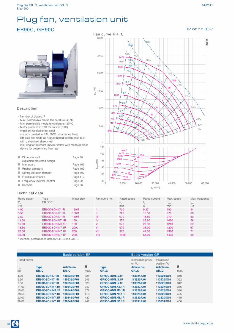
Technical dataRated power Type Motor size Fan curve no. Rated speed Rated current Max. speed Max. frequencyPN ER / GR* nN IN nmax fmaxkW min-1 A min-1 Hz4.00 ER90C-8DN.I7.1R 160M I 720 9.37 780 545.50 ER90C-8DN.I7.1R 160M II 720 12.50 870 607.50 ER90C-6DN.I7.1R 160M III 970 15.80 970 5011.00 ER90C-6DN.K7.1R 160L IV 970 22.60 1090 5615.00 ER90C-6DN.M7.1R 180L V 970 29.30 1210 6218.50 ER90C-6DN.N7.1R 200L VI 970 35.90 1300 6722.00 ER90C-6DN.N7.1R 200L VII 970 41.50 1380 7130.00 ER90C-4DN.N7.1R 200L VIII 1480 54.00 1475 50* Identical performance data for ER..C and GR..C
Basic version ER Basic version GR
Rated power Installation positi-on Vu
Installation position Vo
PN Type Article no. Type Article no. Article no. kW ER..C ER..C max. GR..C GR..C GR..C max.
4.00 ER90C-8DN.I7.1R 130537/0F01 324 GR90C-8DN.I5.1R 113824/U01 113824/O01 3405.50 ER90C-8DN.I7.1R 130538/0F01 346 GR90C-8DN.I5.1R 113825/U01 113825/O01 3627.50 ER90C-6DN.I7.1R 130539/0F01 326 GR90C-6DN.I5.1R 113826/U01 113826/O01 34211.00 ER90C-6DN.K7.1R 130540/0F01 340 GR90C-6DN.K5.1R 113827/U01 113827/O01 35615.00 ER90C-6DN.M7.1R 130541/0F01 378 GR90C-6DN.M5.1R 113828/U01 113828/O01 39018.50 ER90C-6DN.N7.1R 130542/0F01 416 GR90C-6DN.N5.1R 113829/U01 113829/O01 42522.00 ER90C-6DN.N7.1R 130543/0F01 430 GR90C-6DN.N5.1R 113830/U01 113830/O01 43930.00 ER90C-4DN.N7.1R 130544/0F01 447 GR90C-4DN.N5.1R 113831/U01 113831/O01 456
Dimensions of explosion protected design
Page 88
Inlet guard Page 109Rubber dampers Page 109Spring vibration damper Page 109Flexible air intakes Page 110Frequency inverter Icontrol Page 92Sensors Page 96
Description
- Number of blades: 7 - Max. permissible media temperature: 40°C - Min. permissible media temperature: -20°C - Motor protection: PTC thermistor (PTC) - Impeller: Welded sheet steel coated / painted in RAL 5002 (ultramarine blue)
- ER-plug fan made as rugged bolted construction built with galvanised sheet steel
- Inlet ring for optimum impeller inflow with measurement device for determining flow rate
Fan curve RH..C
Plug fan, ventilation unitMotor IE2ER90C, GR90C
78 www.ziehl-abegg.com
Plug fan ER..C, ventilation unit GR..C 04/2011Size 900
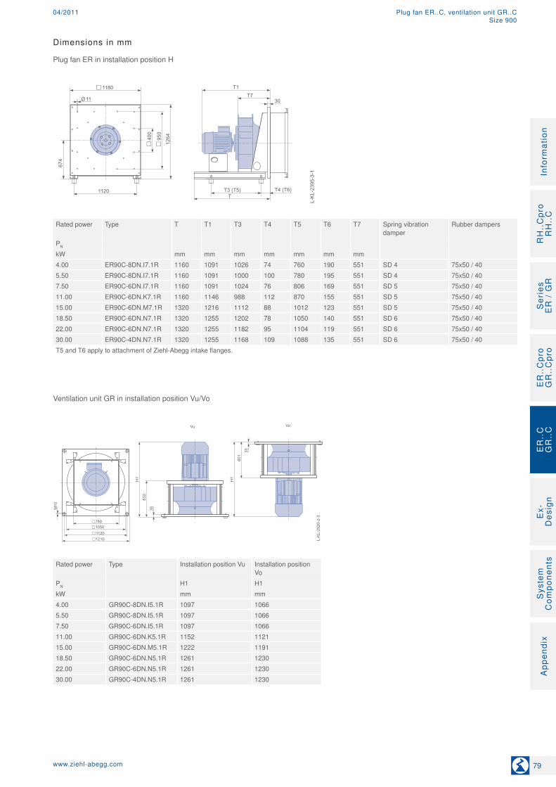
Dimensions in mm
Plug fan ER in installation position H
L-K
L-23
95-3
-1
1120T
T1T7
T3 (T5)
1264
674
1180
30
T4 (T6)
950
400
11Ø
Rated power Type T T1 T3 T4 T5 T6 T7 Spring vibration
damperRubber dampers
PN
kW mm mm mm mm mm mm mm4.00 ER90C-8DN.I7.1R 1160 1091 1026 74 760 190 551 SD 4 75x50 / 405.50 ER90C-8DN.I7.1R 1160 1091 1000 100 780 195 551 SD 4 75x50 / 407.50 ER90C-6DN.I7.1R 1160 1091 1024 76 806 169 551 SD 5 75x50 / 4011.00 ER90C-6DN.K7.1R 1160 1146 988 112 870 155 551 SD 5 75x50 / 4015.00 ER90C-6DN.M7.1R 1320 1216 1112 88 1012 123 551 SD 5 75x50 / 4018.50 ER90C-6DN.N7.1R 1320 1255 1202 78 1050 140 551 SD 6 75x50 / 4022.00 ER90C-6DN.N7.1R 1320 1255 1182 95 1104 119 551 SD 6 75x50 / 4030.00 ER90C-4DN.N7.1R 1320 1255 1168 109 1088 135 551 SD 6 75x50 / 40T5 and T6 apply to attachment of Ziehl-Abegg intake flanges.
Ventilation unit GR in installation position Vu/Vo
L-KL-2520-2-3
Vu Vo
H1
632
35
H1
601
35
M10
1210
1120
780
1050
Rated power Type Installation position Vu Installation position Vo
PN H1 H1kW mm mm4.00 GR90C-8DN.I5.1R 1097 10665.50 GR90C-8DN.I5.1R 1097 10667.50 GR90C-6DN.I5.1R 1097 106611.00 GR90C-6DN.K5.1R 1152 112115.00 GR90C-6DN.M5.1R 1222 119118.50 GR90C-6DN.N5.1R 1261 123022.00 GR90C-6DN.N5.1R 1261 123030.00 GR90C-4DN.N5.1R 1261 1230
79www.ziehl-abegg.com
RH
..C
pro
RH
..C
Ser
ies
E
R /
GR
ER
..C
pro
GR
..C
pro
Ex-
Des
ign
Sys
tem
C
ompo
nent
sA
ppen
dix
Info
rmat
ion
ER
..C
GR
..C
Plug fan ER..C, ventilation unit GR..C04/2011Size 900
80
85
90
95
100
105
L WA
5 [d
B]
0 10.000 20.000 30.000 40.000 50.000 60.000 70.000 80.000
qV [m³/h]
990 1060
1250
min-1
1125
890
785
720
1280
I II
III IV
V VI VII
0
500
1.000
1.500
2.000
2.500
3.000
p sF [P
a]
3,0
PL kW
I
II
III
IV 890
990
1060
1250
min-1
50% 60%
73%
67%
67%
58%
45%
37%
73%
73%
1280
720
785
440
570
V
VI
7,5
11,0
5,5
15,0
VII
18,5
22,0
1,5
30,0
1125
VIII
37,0
VIII
ηfaL
8549
0
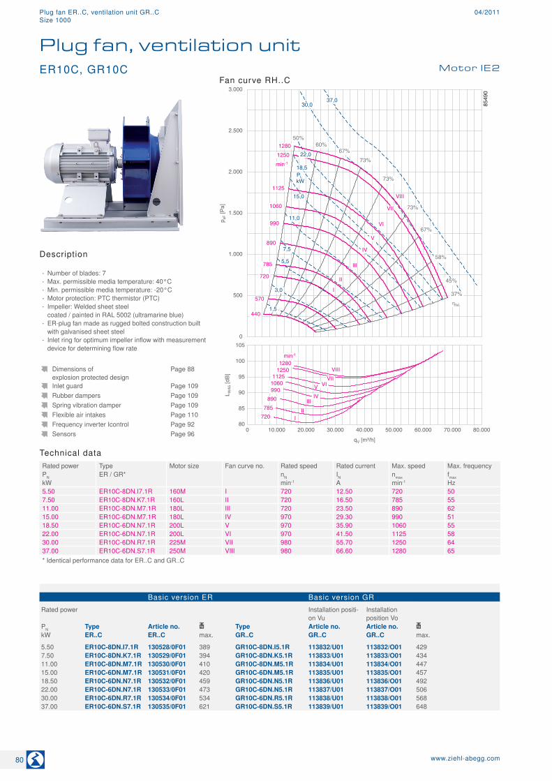
Technical dataRated power Type Motor size Fan curve no. Rated speed Rated current Max. speed Max. frequencyPN ER / GR* nN IN nmax fmaxkW min-1 A min-1 Hz5.50 ER10C-8DN.I7.1R 160M I 720 12.50 720 507.50 ER10C-8DN.K7.1R 160L II 720 16.50 785 5511.00 ER10C-8DN.M7.1R 180L III 720 23.50 890 6215.00 ER10C-6DN.M7.1R 180L IV 970 29.30 990 5118.50 ER10C-6DN.N7.1R 200L V 970 35.90 1060 5522.00 ER10C-6DN.N7.1R 200L VI 970 41.50 1125 5830.00 ER10C-6DN.R7.1R 225M VII 980 55.70 1250 6437.00 ER10C-6DN.S7.1R 250M VIII 980 66.60 1280 65* Identical performance data for ER..C and GR..C
Basic version ER Basic version GR
Rated power Installation positi-on Vu
Installation position Vo
PN Type Article no. Type Article no. Article no. kW ER..C ER..C max. GR..C GR..C GR..C max.
5.50 ER10C-8DN.I7.1R 130528/0F01 389 GR10C-8DN.I5.1R 113832/U01 113832/O01 4297.50 ER10C-8DN.K7.1R 130529/0F01 394 GR10C-8DN.K5.1R 113833/U01 113833/O01 43411.00 ER10C-8DN.M7.1R 130530/0F01 410 GR10C-8DN.M5.1R 113834/U01 113834/O01 44715.00 ER10C-6DN.M7.1R 130531/0F01 420 GR10C-6DN.M5.1R 113835/U01 113835/O01 45718.50 ER10C-6DN.N7.1R 130532/0F01 459 GR10C-6DN.N5.1R 113836/U01 113836/O01 49222.00 ER10C-6DN.N7.1R 130533/0F01 473 GR10C-6DN.N5.1R 113837/U01 113837/O01 50630.00 ER10C-6DN.R7.1R 130534/0F01 534 GR10C-6DN.R5.1R 113838/U01 113838/O01 56837.00 ER10C-6DN.S7.1R 130535/0F01 621 GR10C-6DN.S5.1R 113839/U01 113839/O01 648
Dimensions of explosion protected design
Page 88
Inlet guard Page 109Rubber dampers Page 109Spring vibration damper Page 109Flexible air intakes Page 110Frequency inverter Icontrol Page 92Sensors Page 96
ER10C, GR10C Motor IE2
Plug fan, ventilation unit
Description
- Number of blades: 7 - Max. permissible media temperature: 40°C - Min. permissible media temperature: -20°C - Motor protection: PTC thermistor (PTC) - Impeller: Welded sheet steel coated / painted in RAL 5002 (ultramarine blue)
- ER-plug fan made as rugged bolted construction built with galvanised sheet steel
- Inlet ring for optimum impeller inflow with measurement device for determining flow rate
Fan curve RH..C
80 www.ziehl-abegg.com
Plug fan ER..C, ventilation unit GR..C 04/2011Size 1000

Dimensions in mm
Plug fan ER in installation position H
L-K
L-23
95-3
-2
1120T
T1T7
T3 (T5)
1264
674
1180
30
T4 (T6)
950
400
11Ø
Rated power Type T T1 T3 T4 T5 T6 T7 Spring vibration
damperRubber dampers
PN
kW mm mm mm mm mm mm mm5.50 ER10C-8DN.I7.1R 1160 1157 936 165 828 202 616 SD 4 75x50 / 407.50 ER10C-8DN.K7.1R 1160 1212 960 165 884 186 616 SD 5 75x50 / 4011.00 ER10C-8DN.M7.1R 1320 1282 1134 87 1104 86 616 SD 5 75x50 / 4015.00 ER10C-6DN.M7.1R 1320 1282 1092 129 1062 128 616 SD 5 75x50 / 4018.50 ER10C-6DN.N7.1R 1320 1321 1152 133 1096 146 616 SD 6 75x50 / 4022.00 ER10C-6DN.N7.1R 1320 1321 1138 147 1160 121 616 SD 6 75x50 / 4030.00 ER10C-6DN.R7.1R 1320 1357 1062 223 1090 195 616 SD 6 75x50 / 4037.00 ER10C-6DN.S7.1R 1320 1427 954 331 980 305 616 SD 7 75x50 / 40T5 and T6 apply to attachment of Ziehl-Abegg intake flanges.
Ventilation unit GR in installation position Vu/Vo
L-KL-2520-2-4
Vu Vo
H1
696,5
35
H1
665,5 35
M10
1340
1250
910
1180
Rated power Type Installation position Vu Installation position Vo
PN H1 H1kW mm mm5.50 GR10C-8DN.I5.1R 1162 11317.50 GR10C-8DN.K5.1R 1217 118611.00 GR10C-8DN.M5.1R 1287 125615.00 GR10C-6DN.M5.1R 1287 125618.50 GR10C-6DN.N5.1R 1326 129522.00 GR10C-6DN.N5.1R 1326 129530.00 GR10C-6DN.R5.1R 1362 133137.00 GR10C-6DN.S5.1R 1432 1401
81www.ziehl-abegg.com
RH
..C
pro
RH
..C
Ser
ies
E
R /
GR
ER
..C
pro
GR
..C
pro
Ex-
Des
ign
Sys
tem
C
ompo
nent
sA
ppen
dix
Info
rmat
ion
ER
..C
GR
..C
Plug fan ER..C, ventilation unit GR..C04/2011Size 1000
85
90
95
100
L WA
5 [d
B]
0 10.000 20.000 30.000 40.000 50.000 60.000 70.000 80.000 90.000
qV [m³/h]
1030
min-1
935
880
825 I
II
III
IV
0
500
1.000
1.500
2.000
2.500
p sF [P
a]
PL
kW
I
II
III
IV
760
825
880
min-1
50% 60%
73%
67%
69%
60%
45%
37%
ηfaL
73%
73%
1030
600
670
380
480
7,5
5,5
15,0
18,5
22,0
30,0
935
3,0
1,5
11,0
8715
0
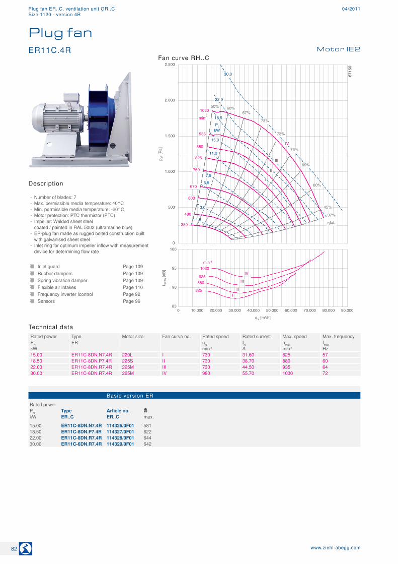
Technical dataRated power Type Motor size Fan curve no. Rated speed Rated current Max. speed Max. frequencyPN ER nN IN nmax fmaxkW min-1 A min-1 Hz15.00 ER11C-8DN.N7.4R 220L I 730 31.60 825 5718.50 ER11C-8DN.P7.4R 225S II 730 38.70 880 6022.00 ER11C-8DN.R7.4R 225M III 730 44.50 935 6430.00 ER11C-6DN.R7.4R 225M IV 980 55.70 1030 72
Basic version ER
Rated power PN Type Article no. kW ER..C ER..C max.
15.00 ER11C-8DN.N7.4R 114326/0F01 58118.50 ER11C-8DN.P7.4R 114327/0F01 62222.00 ER11C-8DN.R7.4R 114328/0F01 64430.00 ER11C-6DN.R7.4R 114329/0F01 642
Inlet guard Page 109Rubber dampers Page 109Spring vibration damper Page 109Flexible air intakes Page 110Frequency inverter Icontrol Page 92Sensors Page 96
Description
- Number of blades: 7 - Max. permissible media temperature: 40°C - Min. permissible media temperature: -20°C - Motor protection: PTC thermistor (PTC) - Impeller: Welded sheet steel coated / painted in RAL 5002 (ultramarine blue)
- ER-plug fan made as rugged bolted construction built with galvanised sheet steel
- Inlet ring for optimum impeller inflow with measurement device for determining flow rate
Fan curve RH..CMotor IE2
Plug fanER11C.4R
82 www.ziehl-abegg.com
Plug fan ER..C, ventilation unit GR..C 04/2011Size 1120 - version 4R
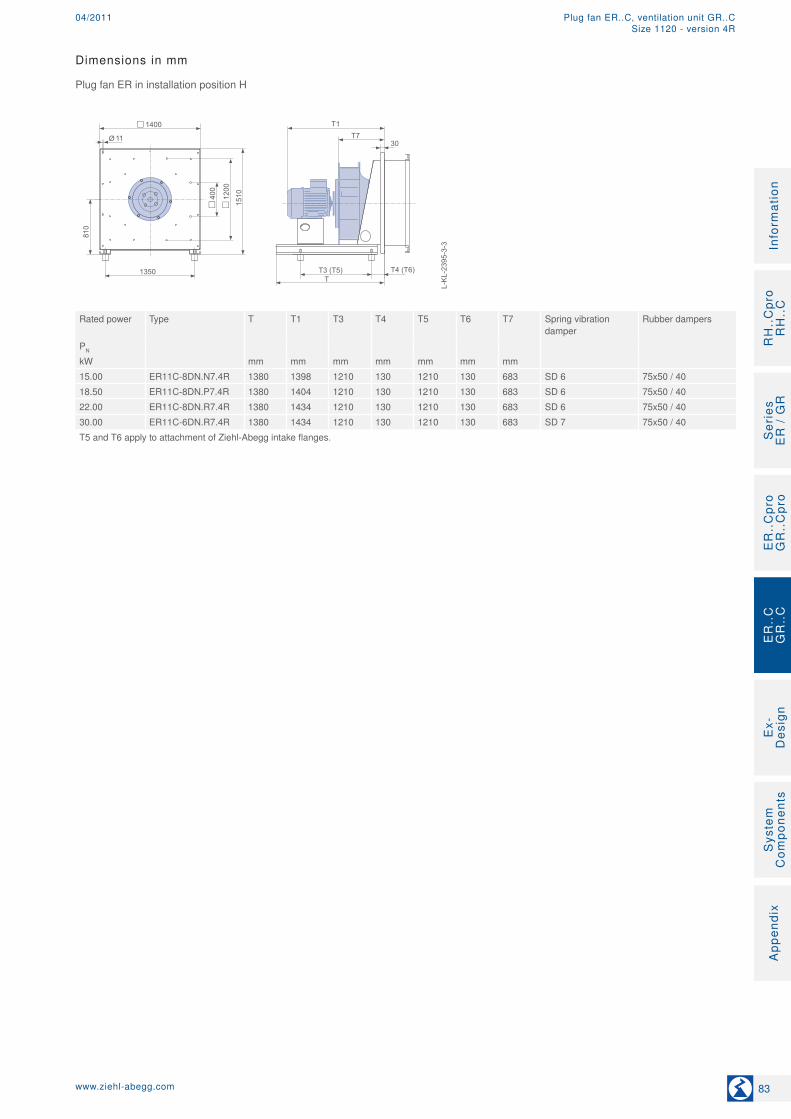
Dimensions in mm
Plug fan ER in installation position H
L-K
L-23
95-3
-3
1350T
T1T7
T3 (T5)
1510
810
1400
30
T4 (T6)
1200
400
11Ø
Rated power Type T T1 T3 T4 T5 T6 T7 Spring vibration
damperRubber dampers
PN
kW mm mm mm mm mm mm mm15.00 ER11C-8DN.N7.4R 1380 1398 1210 130 1210 130 683 SD 6 75x50 / 4018.50 ER11C-8DN.P7.4R 1380 1404 1210 130 1210 130 683 SD 6 75x50 / 4022.00 ER11C-8DN.R7.4R 1380 1434 1210 130 1210 130 683 SD 6 75x50 / 4030.00 ER11C-6DN.R7.4R 1380 1434 1210 130 1210 130 683 SD 7 75x50 / 40T5 and T6 apply to attachment of Ziehl-Abegg intake flanges.
83www.ziehl-abegg.com
RH
..C
pro
RH
..C
Ser
ies
E
R /
GR
ER
..C
pro
GR
..C
pro
Ex-
Des
ign
Sys
tem
C
ompo
nent
sA
ppen
dix
Info
rmat
ion
ER
..C
GR
..C
Plug fan ER..C, ventilation unit GR..C04/2011Size 1120 - version 4R
80
85
90
95
100
105
110
L WA
5 [d
B]
0 20.000 40.000 60.000 80.000 100.000 120.000
qV [m³/h]
990 1050
1200
min-1
1130
890 845 790
1320
I II
III IV V VI
VII VIII
0
500
1.000
1.500
2.000
2.500
3.000
3.500
p sF [P
a]
PL
kW
I
II
III
IV 890
990
1050
1200
min-1
50% 60%
73%
67%
66%
56%
45%
37%
73%
73%
1320
790
845
450
630
V
VI
7,5
5,5
15,0
VII
18,5
22,0
30,0 1130
VIII
37,0
75,0 55,0
45,0
ηfaL
8553
5
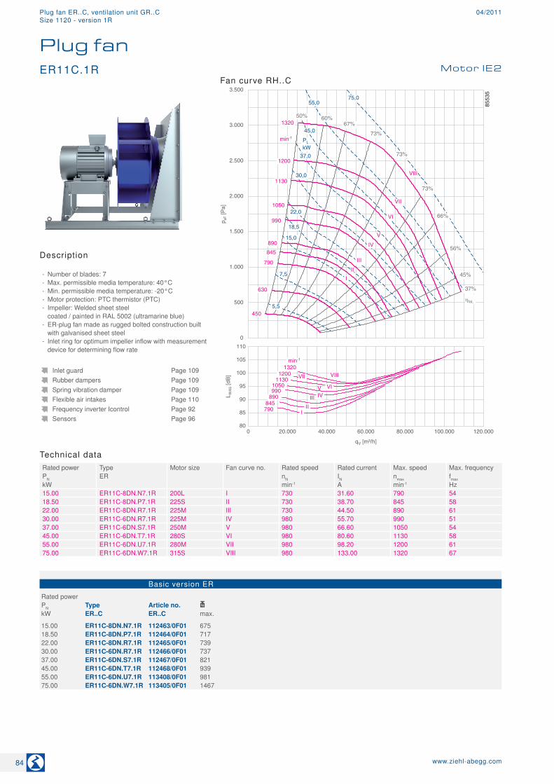
Technical dataRated power Type Motor size Fan curve no. Rated speed Rated current Max. speed Max. frequencyPN ER nN IN nmax fmaxkW min-1 A min-1 Hz15.00 ER11C-8DN.N7.1R 200L I 730 31.60 790 5418.50 ER11C-8DN.P7.1R 225S II 730 38.70 845 5822.00 ER11C-8DN.R7.1R 225M III 730 44.50 890 6130.00 ER11C-6DN.R7.1R 225M IV 980 55.70 990 5137.00 ER11C-6DN.S7.1R 250M V 980 66.60 1050 5445.00 ER11C-6DN.T7.1R 280S VI 980 80.60 1130 5855.00 ER11C-6DN.U7.1R 280M VII 980 98.20 1200 6175.00 ER11C-6DN.W7.1R 315S VIII 980 133.00 1320 67
Basic version ER
Rated power PN Type Article no. kW ER..C ER..C max.
15.00 ER11C-8DN.N7.1R 112463/0F01 67518.50 ER11C-8DN.P7.1R 112464/0F01 71722.00 ER11C-8DN.R7.1R 112465/0F01 73930.00 ER11C-6DN.R7.1R 112466/0F01 73737.00 ER11C-6DN.S7.1R 112467/0F01 82145.00 ER11C-6DN.T7.1R 112468/0F01 93955.00 ER11C-6DN.U7.1R 113408/0F01 98175.00 ER11C-6DN.W7.1R 113405/0F01 1467
Inlet guard Page 109Rubber dampers Page 109Spring vibration damper Page 109Flexible air intakes Page 110Frequency inverter Icontrol Page 92Sensors Page 96
Description
- Number of blades: 7 - Max. permissible media temperature: 40°C - Min. permissible media temperature: -20°C - Motor protection: PTC thermistor (PTC) - Impeller: Welded sheet steel coated / painted in RAL 5002 (ultramarine blue)
- ER-plug fan made as rugged bolted construction built with galvanised sheet steel
- Inlet ring for optimum impeller inflow with measurement device for determining flow rate
Fan curve RH..CMotor IE2
Plug fanER11C.1R
84 www.ziehl-abegg.com
Plug fan ER..C, ventilation unit GR..C 04/2011Size 1120 - version 1R
Dimensions in mm
Plug fan ER in installation position H
L-K
L-23
95-4
1350
T
T1T7
T3 (T5)
1510
810
1400
30
T4 (T6)
1200
400
T11
11Ø
Rated power Type T T1 T3 T4 T5 T6 T7 T11 Spring vibration
damperRubber dam-pers
PN
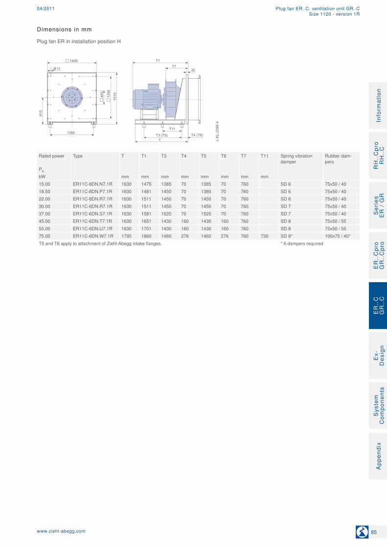
kW mm mm mm mm mm mm mm mm15.00 ER11C-8DN.N7.1R 1630 1475 1385 70 1385 70 760 SD 6 75x50 / 4018.50 ER11C-8DN.P7.1R 1630 1481 1450 70 1385 70 760 SD 6 75x50 / 4022.00 ER11C-8DN.R7.1R 1630 1511 1450 70 1450 70 760 SD 6 75x50 / 4030.00 ER11C-6DN.R7.1R 1630 1511 1450 70 1450 70 760 SD 7 75x50 / 4037.00 ER11C-6DN.S7.1R 1630 1581 1520 70 1520 70 760 SD 7 75x50 / 4045.00 ER11C-6DN.T7.1R 1630 1651 1430 160 1430 160 760 SD 8 75x50 / 5555.00 ER11C-6DN.U7.1R 1630 1701 1430 160 1430 160 760 SD 8 75x50 / 5575.00 ER11C-6DN.W7.1R 1795 1860 1460 276 1460 276 760 730 SD 8* 100x75 / 40*T5 and T6 apply to attachment of Ziehl-Abegg intake flanges. * 6 dampers required
85www.ziehl-abegg.com
RH
..C
pro
RH
..C
Ser
ies
E
R /
GR
ER
..C
pro
GR
..C
pro
Ex-
Des
ign
Sys
tem
C
ompo
nent
sA
ppen
dix
Info
rmat
ion
ER
..C
GR
..C
Plug fan ER..C, ventilation unit GR..C04/2011Size 1120 - version 1R
Measuring device for determining air volume Page 19Rubber or spring dampers Page 109Description of high-performance impeller Page 20Standard version Page 28Frequency inverter Icontrol Page 92
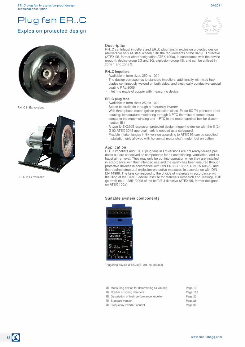
DescriptionRH..C centrifugal impellers and ER..C plug fans in explosion protected design (deliverable only as steel wheel) fulfill the requirements of the 94/9/EU directive (ATEX 95, former short designation ATEX 100a), in accordance with the device group II, device group 2G and 3G, explosion group IIB, and can be utilised in zone 1 and zone 2. RH..C impellers
- Available in form sizes 250 to 1000 - The design corresponds to standard impellers, additionally with fixed hub, blades continuously welded on both sides, and electrically conductive special coating RAL 9005
- Inlet ring made of copper with measuring device ER..C plug fans
- Available in form sizes 250 to 1000 - Speed controllable through a frequency inverter - With three phase motor ignition protection class, Ex de IIC T4 pressure-proof housing; temperature monitoring through 3 PTC thermistors-temperature sensor in the motor winding and 1 PTC in the motor terminal box for discon-nection IE1
- A type U-EK230E explosion-protected design triggering-device with the II (2)G 03 ATEX 3045 approval mark is needed as a safeguard.
- Flexible intake flanges in Ex-version according to ATEX 95 can be supplied - Installation only allowed with horizontal motor shaft; motor feet on button
ApplicationRH..C impellers and ER..C plug fans in Ex-versions are not ready-for-use pro-ducts but are conceived as components for air conditioning, ventilation, and ex-haust air removal. They may only be put into operation when they are installed in accordance with their intended use and the safety has been ensured through protective devices in accordance with DIN EN ISO 13857, DIN EN 60529, and the required structural explosion-protective measures in accordance with DIN EN 14986. The fans correspond to the choice of materials in accordance with the filing at the BAM (Federal Institute for Materials Research and Testing), TGB (journal) no.: II-2851/2008 of the 94/9/EU directive (ATEX 95, former designati-on ATEX 100a).
Suitable system components
Plug fan ER..CExplosion protected design
ER..C in Ex-versions
RH..C in Ex-versions
Triggering-device U-EK230E, Art. no. 382000
86 www.ziehl-abegg.com
04/2011ER..C plug fan in explosion-proof designTechnical description
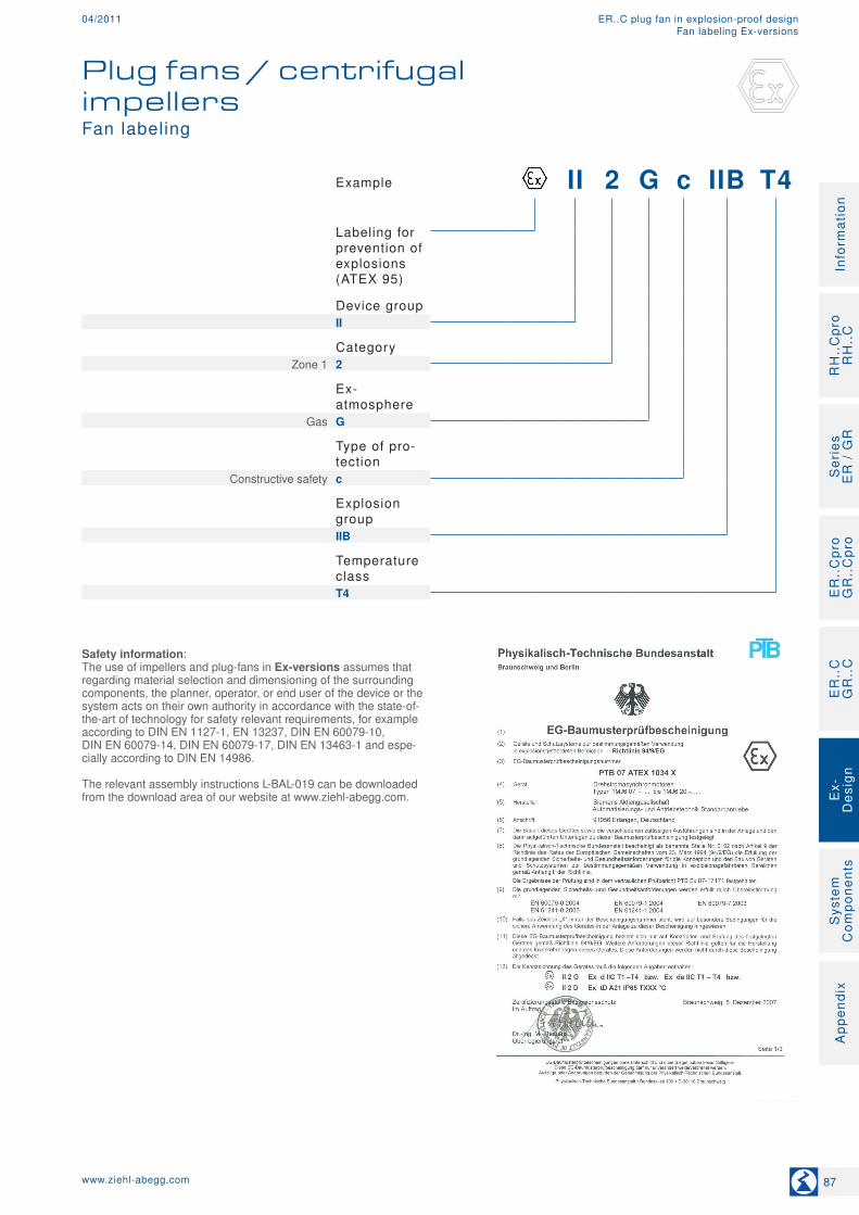
Example II 2 G c IIB T4
Labeling for prevention of explosions (ATEX 95)
Device group
II
Category
Zone 1 2
Ex- atmosphere
Gas G
Type of pro-tection
Constructive safety c
Explosion group
IIB
Temperature class
T4
Safety information:The use of impellers and plug-fans in Ex-versions assumes that regarding material selection and dimensioning of the surrounding components, the planner, operator, or end user of the device or the system acts on their own authority in accordance with the state-of-the-art of technology for safety relevant requirements, for example according to DIN EN 1127-1, EN 13237, DIN EN 60079-10, DIN EN 60079-14, DIN EN 60079-17, DIN EN 13463-1 and espe-cially according to DIN EN 14986. The relevant assembly instructions L-BAL-019 can be downloaded from the download area of our website at www.ziehl-abegg.com.
Fan labeling
Plug fans / centrifugal impellers
87www.ziehl-abegg.com
RH
..C
pro
RH
..C
Ser
ies
E
R /
GR
ER
..C
pro
GR
..C
pro
Ex-
Des
ign
Sys
tem
C
ompo
nent
sA
ppen
dix
Info
rmat
ion
ER
..C
GR
..C
04/2011 ER..C plug fan in explosion-proof designFan labeling Ex-versions