NL Montage handleiding VH1970704-4 - Suspension Shop
5
Volkswagen Sharan / Seat Alhambra / Ford Galaxy KITNR: NR-197046 GB Mounting instruction VH1970704-4 NL Montage handleiding VH1970704-4 D Montage Anleitung VH1970704-4
Transcript of NL Montage handleiding VH1970704-4 - Suspension Shop
Volkswagen Sharan / Seat Alhambra / Ford Galaxy KITNR: NR-197046
GB Mounting instruction VH1970704-4
NL Montage handleiding VH1970704-4
D Montage Anleitung VH1970704-4
2
MOUNTING INSTRUCTIONS KITNR: NR-197046
1-4
4A
3
NL Demonteer de onderste schokdemperbout en hef de auto uit de veren totdat de hoofdveer verwijdert kan worden.
GB Dismount the lower shockabsorberbolt and jack up the car untill the mainspring can be removed.
1
D Demontieren Sie den unteren Stoßdämpferbolzen und heben Sie das Fahrzeug an bis die Hauptfeder demontiert werden kann.
NL Verwijder de buffer. Deze wordt niet meer gebruikt.
GB Remove the bumpstop. The bumpstop will not be used again.
D Demontieren Sie den Puffer. Der Puffer brauchen Sie nicht mehr.
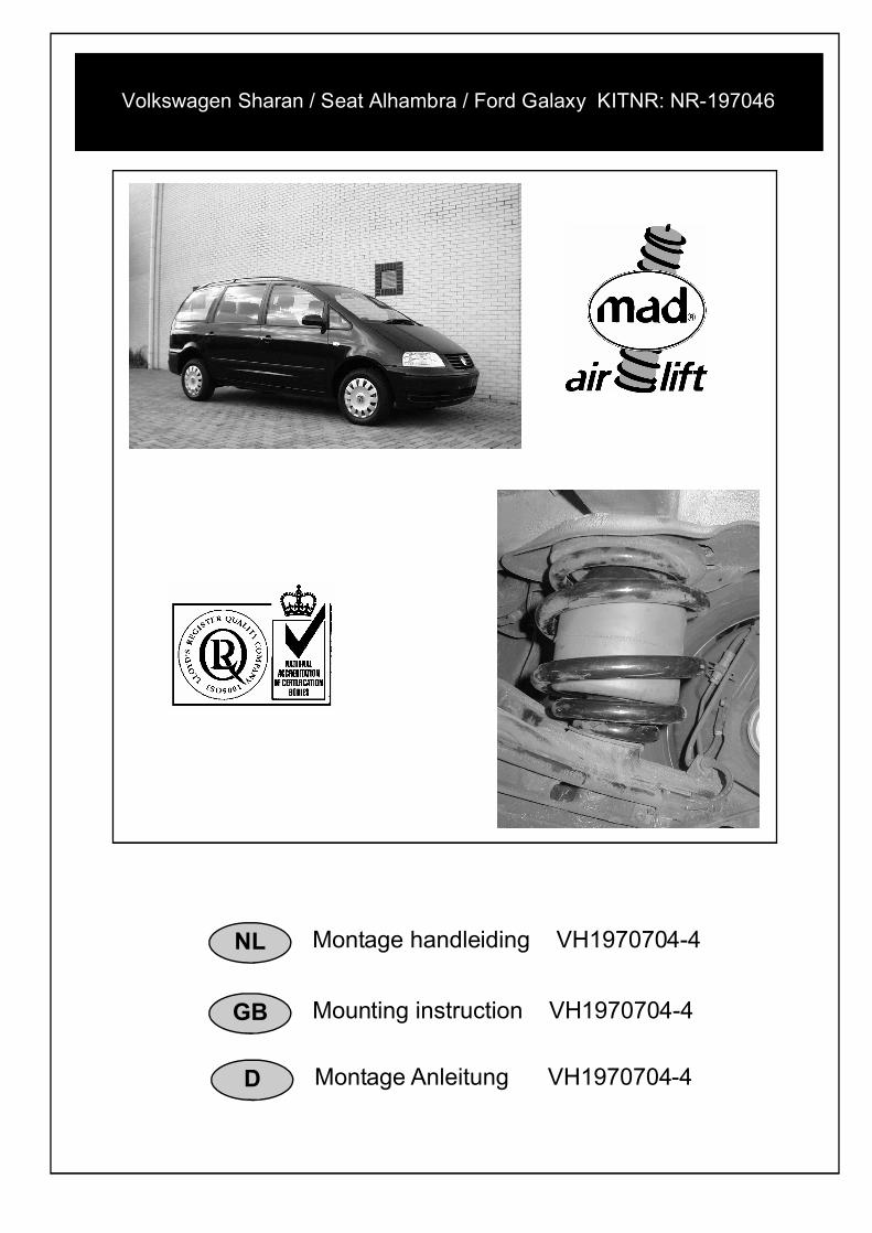
NL Boor een gat van ø 8mm in het gat waar de buffer in gemonteerd was.
GB Drill a hole of ø 8mm in the hole where the bumpstop was mounted.
D Bohren Sie ein Loch von ø 8mm in das Loch wo der Puffer montiert war.
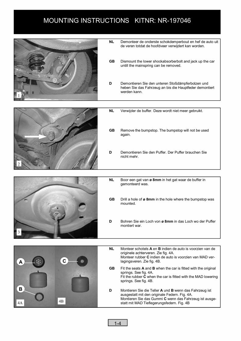
NL Monteer schotels A en B indien de auto is voorzien van de originele achterveren. Zie fig. 4A. Monteer rubber C indien de auto is voorzien van MAD ver- lagingsveren. Zie fig. 4B.
GB Fit the seats A and B when the car is fitted with the original springs. See fig. 4A.Fit the rubber C when the car is fitted with the MAD lowering springs. See fig. 4B.
D Montieren Sie die Teller A und B wenn das Fahrzeug ist ausgestatt mit den originale Federn. Fig. 4A.Montieren Sie das Gummi C wenn das Fahrzeug ist ausge-statt mit MAD Tieflegerungsfedern. Fig. 4B4B
C
B
A
7
MOUNTING INSTRUCTIONS KITNR: NR-197046
2-4
8
6
5
B
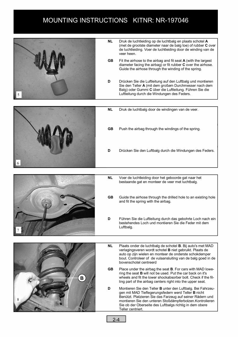
NL Druk de luchtleiding op de luchtbalg en plaats schotel A(met de grootste diameter naar de balg toe) of rubber C over de luchtleiding. Voer de luchtleiding door de winding van de
veer heen.
GB Fit the airhose to the airbag and fit seat A (with the largest diameter facing the airbag) or fit rubber C over the airhose. Guide the airhose through the winding of the spring.
D Drücken Sie die Luftleitung auf den Luftbalg und montieren Sie den Teller A (mit dem großem Durchmesser nach dem Balg) oder Gummi C über die Luftleitung. Führen Sie die Luftleitung durch die Windungen des Feders.
NL Druk de luchtbalg door de windingen van de veer.
GB Push the airbag through the windings of the spring.
D Drücken Sie den Luftbalg durch die Windungen des Feders.
NL Voer de luchtleiding door het geboorde gat naar het bestaande gat en monteer de veer met luchtbalg.
GB Guide the airhose through the drilled hole to an existing hole and fit the spring with the airbag.
D Führen Sie die Luftleitung durch das gebohrte Loch nach ein bestehendes Loch und montieren Sie die Feder mit demLuftbalg.
NL Plaats onder de luchtbalg de schotel B. Bij auto's met MAD verlagingsveren wordt schotel B niet gebruikt. Plaats de auto op zijn wielen en monteer de onderste schokdemper bout. Controleer of de vulaansluiting van de balg goed in de
bovenschotel centreerd
GB Place under the airbag the seat B. For cars with MAD lowe-ring the seat B will not be used. Put the car back on it's wheels and fit the lower shockabsorber bolt. Check if the fil- ling part of the airbag centers right into the upper seat.
D Montieren Sie den Teller B unter den Luftbalg. Bei Fahrzeu-gen mit MAD Tieflegerungsfedern werd Teller B nicht Benützt. Platzieren Sie das Farzeug auf seiner Rädern und montieren Sie den unteren Stoßdämpferbolzen.Kontrolieren Sie ob der Oberseite des Luftbalgs richtig in dem obere Teller centriert.
MOUNTING INSTRUCTIONS KITNR: NR-197046
3-3
9
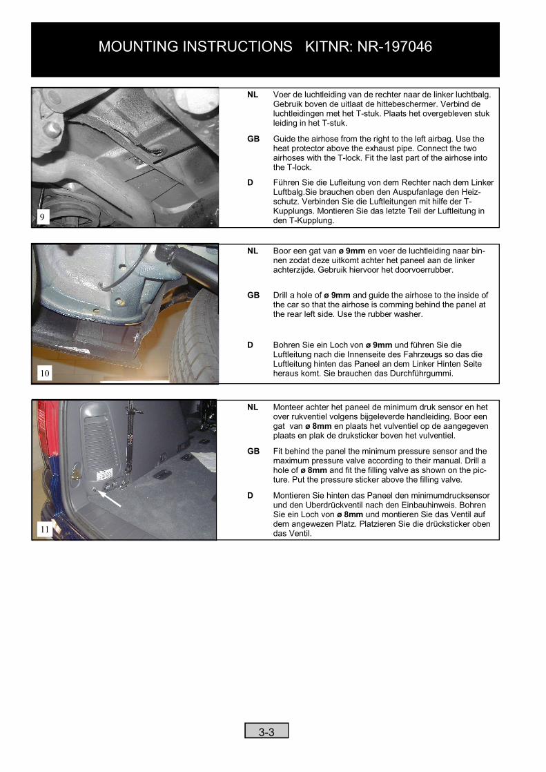
NL Voer de luchtleiding van de rechter naar de linker luchtbalg. Gebruik boven de uitlaat de hittebeschermer. Verbind de luchtleidingen met het T-stuk. Plaats het overgebleven stuk leiding in het T-stuk.
GB Guide the airhose from the right to the left airbag. Use the heat protector above the exhaust pipe. Connect the two airhoses with the T-lock. Fit the last part of the airhose into the T-lock.
D Führen Sie die Lufleitung von dem Rechter nach dem Linker Luftbalg.Sie brauchen oben den Auspufanlage den Heiz- schutz. Verbinden Sie die Luftleitungen mit hilfe der T-Kupplungs. Montieren Sie das letzte Teil der Luftleitung in den T-Kupplung.
10
NL Boor een gat van ø 9mm en voer de luchtleiding naar bin- nen zodat deze uitkomt achter het paneel aan de linker achterzijde. Gebruik hiervoor het doorvoerrubber.
GB Drill a hole of ø 9mm and guide the airhose to the inside of the car so that the airhose is comming behind the panel at the rear left side. Use the rubber washer.
D Bohren Sie ein Loch von ø 9mm und führen Sie die Luftleitung nach die Innenseite des Fahrzeugs so das die Luftleitung hinten das Paneel an dem Linker Hinten Seite heraus komt. Sie brauchen das Durchführgummi.
11
NL Monteer achter het paneel de minimum druk sensor en het over rukventiel volgens bijgeleverde handleiding. Boor een gat van ø 8mm en plaats het vulventiel op de aangegeven
plaats en plak de druksticker boven het vulventiel.
GB Fit behind the panel the minimum pressure sensor and the maximum pressure valve according to their manual. Drill a hole of ø 8mm and fit the filling valve as shown on the pic-ture. Put the pressure sticker above the filling valve.
D Montieren Sie hinten das Paneel den minimumdrucksensor und den Uberdrückventil nach den Einbauhinweis. Bohren Sie ein Loch von ø 8mm und montieren Sie das Ventil auf dem angewezen Platz. Platzieren Sie die drücksticker oben das Ventil.
MOUNTING INSTRUCTIONS KITNR: NR-197046
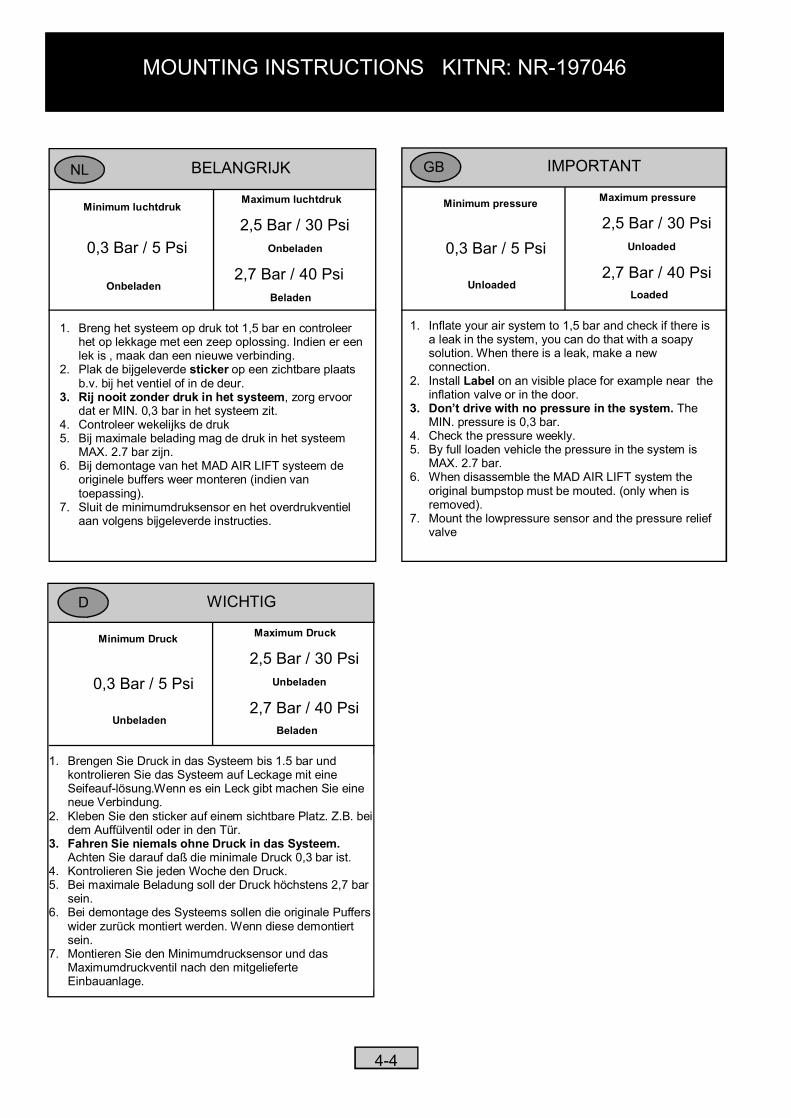
IMPORTANTGB
Minimum pressure
0,3 Bar / 5 Psi
Unloaded
Maximum pressure
2,5 Bar / 30 PsiUnloaded
2,7 Bar / 40 PsiLoaded
1. Inflate your air system to 1,5 bar and check if there is a leak in the system, you can do that with a soapy solution. When there is a leak, make a new connection.
2. Install Label on an visible place for example near the inflation valve or in the door.
3. Don’t drive with no pressure in the system. TheMIN. pressure is 0,3 bar.
4. Check the pressure weekly.5. By full loaden vehicle the pressure in the system is
MAX. 2.7 bar.6. When disassemble the MAD AIR LIFT system the
original bumpstop must be mouted. (only when is removed).
7. Mount the lowpressure sensor and the pressure relief valve
BELANGRIJK
Minimum luchtdruk
0,3 Bar / 5 Psi
Onbeladen
Maximum luchtdruk
2,5 Bar / 30 PsiOnbeladen
2,7 Bar / 40 PsiBeladen
1. Breng het systeem op druk tot 1,5 bar en controleer het op lekkage met een zeep oplossing. Indien er een lek is , maak dan een nieuwe verbinding.
2. Plak de bijgeleverde sticker op een zichtbare plaats b.v. bij het ventiel of in de deur.
3. Rij nooit zonder druk in het systeem, zorg ervoor dat er MIN. 0,3 bar in het systeem zit.
4. Controleer wekelijks de druk5. Bij maximale belading mag de druk in het systeem
MAX. 2.7 bar zijn.6. Bij demontage van het MAD AIR LIFT systeem de
originele buffers weer monteren (indien van toepassing).
7. Sluit de minimumdruksensor en het overdrukventiel aan volgens bijgeleverde instructies.
NL
4-4
WICHTIGD
Minimum Druck
0,3 Bar / 5 Psi
Unbeladen
Maximum Druck
2,5 Bar / 30 PsiUnbeladen
2,7 Bar / 40 PsiBeladen
1. Brengen Sie Druck in das Systeem bis 1.5 bar und kontrolieren Sie das Systeem auf Leckage mit eine Seifeauf-lösung.Wenn es ein Leck gibt machen Sie eine neue Verbindung.
2. Kleben Sie den sticker auf einem sichtbare Platz. Z.B. bei dem Auffülventil oder in den Tür.
3. Fahren Sie niemals ohne Druck in das Systeem. Achten Sie darauf daß die minimale Druck 0,3 bar ist.
4. Kontrolieren Sie jeden Woche den Druck.5. Bei maximale Beladung soll der Druck höchstens 2,7 bar
sein.6. Bei demontage des Systeems sollen die originale Puffers
wider zurück montiert werden. Wenn diese demontiert sein.
7. Montieren Sie den Minimumdrucksensor und das Maximumdruckventil nach den mitgelieferte Einbauanlage.