NASA TECHNICAL MEMORANDUM NASA TM-7013 SOME … · NASA TECHNICAL MEMORANDUM NASA TM-7013 SOME...
33
NASA TECHNICAL MEMORANDUM NASA TM-7013 SOME CHARACTERISTIC QUANTITIES OF KARMAN-TREFFTZ PROFILES J, J. H. Blom Translation o£ "Enige Karateristieke Grootheden Van Von Karman-Trefftz "Profielen", Technische Hogeschool, Delft (Netherlands). Department of Aerospace Engineering, Report No. VTH-LR-323, June 1981, 40 pp. NATIONAL AERONAUTICS AND SPACE ADMINISTRATION WASHINGTON, D.C. 20546 JANUARY 1983 https://ntrs.nasa.gov/search.jsp?R=19830012644 2020-01-17T07:44:09+00:00Z
Transcript of NASA TECHNICAL MEMORANDUM NASA TM-7013 SOME … · NASA TECHNICAL MEMORANDUM NASA TM-7013 SOME...
NASA TECHNICAL MEMORANDUM NASA TM-7013
SOME CHARACTERISTIC QUANTITIES OF KARMAN-TREFFTZ PROFILES
J, J. H. Blom
Translation o£ "Enige Karateristieke Grootheden Van VonKarman-Trefftz "Profielen", Technische Hogeschool, Delft(Netherlands). Department of Aerospace Engineering,Report No. VTH-LR-323, June 1981, 40 pp.
NATIONAL AERONAUTICS AND SPACE ADMINISTRATIONWASHINGTON, D.C. 20546 JANUARY 1983
https://ntrs.nasa.gov/search.jsp?R=19830012644 2020-01-17T07:44:09+00:00Z
STAN&A0O TlTtf
1. R«»««i N*.NASA TM-77013
2. G«v«rfM*«<ii AccxtlM M*. 3. Riclplmtt't C«««l»t N».
4. Till. 9*4 V.VHIU
SOME CHARACTERISTIC QUANTITIES OFKARMAN-TREFFTZ PROFILES
$. O»«» 0»»» i r> o ?January 1983. P«rf«rmln| O'|an
7. I. O'f«nil«tl«n N«.
J. J. H. Blom 10. Ward Unit N».
9. Ptrfo'ming Orgonii*li»n Nam* «n
SCITRANBox 5456Santia Barbara. CA.
II. Contract «r C'«nl H».NASw 35 U2
II.
Translation12. SpatfC
ftatTonar'Aercmautics and Space AdnlniatratlonWashington, D.C. 20546 14.
Translation of- "Enige Karateristieke Grootheden Van VonKarman-Treff tz Profielen", Technische Hogeschool, Delft(Netherlands). Department of Aerospace Engineering, ReportNo. VTH-LR-323, June 1981, 40 pp. (N82-19189)
For von Karman-Trefftz profiles, the characteristics whichdetermine profile shape (profile nose dimensions, maximumthickness and position; tail slope and curvature) are statedas a function of transformation variables using the Timmanmethod. The profile is obtained by iterative deformationof a von Karman profile with known transformation corresponding as well as possible to the desired profile. The figuresand relations which enable a good choice of the required pro-file are given.
19. Key «•*<« (S««U4 fey A It. OUtriWMo*
Unclassified - Unlimited
If. S«««r*hr O«t»lf. (.1 «!•
L_VMvrity CUtdf. M iMt »«*W
OnclM«lfi«d 33n. r««»
Summary /i
The conform transformation for a given random profile can be determined by
means of the method designed by Timman (7). Here an auxiliary or starting profile
is used of which the transformation is known and which is as consistent as possible
with the given profile.
This starting profile is then deformed by iteration until the desired profile
shape is achieved.
A Karman-Trefftz profile is used for the starting profile.
\ For these profiles the characteristic quantities which determine the profile
shape, such as the size of the radius of the nose, the maximum thickness and position
of the thickness as well as the slope of the tail and arching [are determined as a function
of the transformation variables. With the figures and drawings presented in this
article it is possible to choose well the required starting profile.
-1-
Contents Page /ii
1. Introduction 3
2. Von Karman-Trefftz profiles 5
3. The slope of the tail and the arch 7
4. The chord of the profile 8
5. The radius of the profile nose 9
5.1 Symmetrical profiles H
5.2 Arched profiles 12
6. The profile shape 13
7. The maximum profile thickness 14
7.1 Symmetrical Joukowsky profiles 14
7.2 Symmetrical von Karman-Trefftz profiles 15
8. Literature 16
-2-
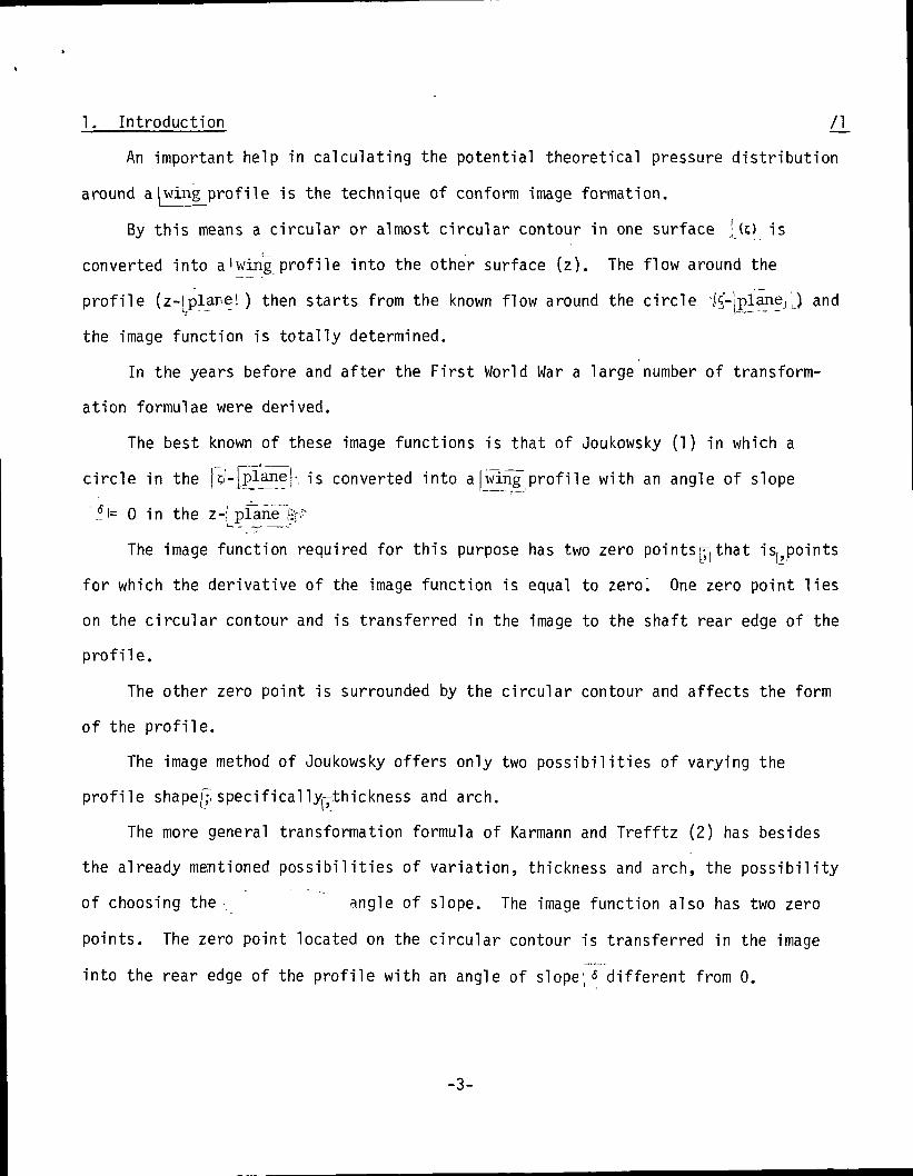
1. Introduction /]_
An important help in calculating the potential theoretical pressure distribution
around a|wing profile is the technique of conform image formation.
By this means a circular or almost circular contour in one surface ' (;) is
converted into a'wing profile into the other surface (z). The flow around the
profile (z-lplarel ) then starts from the known flow around the circle l5-jplanej,) and
the image function is totally determined.
In the years before and after the First World War a large number of transform-
ation formulae were derived.
The best known of these image functions is that of Joukowsky (1) in which a
circle in the ]d-|planer is converted into a[wing profile with an angle of slope
' ?.i= 0 in the z-jjplan~e~
The image function required for this purpose has two zero pointsr^that isf> points
for which the derivative of the image function is equal to zero". One zero point lies
on the circular contour and is transferred in the image to the shaft rear edge of the
profile.
The other zero point is surrounded by the circular contour and affects the form
of the profile.
The image method of Joukowsky offers only two possibilities of varying the
profile shape|^ specifically^-thickness and arch.
The more general transformation formula of Karmann and Trefftz (2) has besides
the already mentioned possibilities of variation, thickness and arch, the possibility
of choosing the., angle of slope. The image function also has two zero
points. The zero point located on the circular contour is transferred in the image
into the rear edge of the profile with an angle of slope1 « different from 0.
-3-
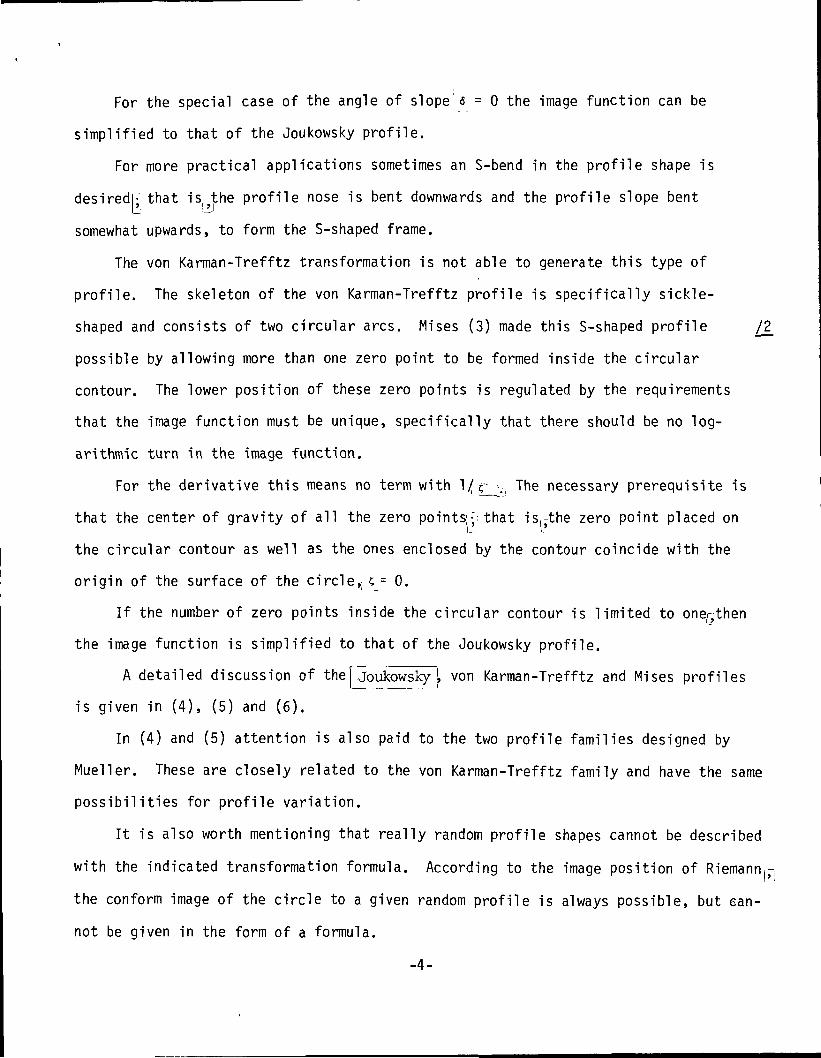
For the special case of the angle of slope 6 = 0 the image function can be
simplified to that of the Joukowsky profile.
For more practical applications sometimes an S-bend in the profile shape is
desiredl; that is?the profile nose is bent downwards and the profile slope bent
somewhat upwards, to form the S-shaped frame.
The von Karman-Trefftz transformation is not able to generate this type of
profile. The skeleton of the von Karman-Trefftz profile is specifically sickle-
shaped and consists of two circular arcs. Mises (3) made this S-shaped profile /2_
possible by allowing more than one zero point to be formed inside the circular
contour. The lower position of these zero points is regulated by the requirements
that the image function must be unique, specifically that there should be no log-
arithmic turn in the image function.
For the derivative this means no term with l/r .( The necessary prerequisite is
that the center of gravity of all the zero pointsi;; that is,-the zero point placed on
the circular contour as well as the ones enclosed by the contour coincide with the
origin of the surface of the circle,; c = 0.
If the number of zero points inside the circular contour is limited to one/^then
the image function is simplified to that of the Joukowsky profile.
A detailed discussion of the| Joukowsky [ von Karman-Trefftz and Mises profiles
is given in (4), (5) and (6).
In (4) and (5) attention is also paid to the two profile families designed by
Mueller. These are closely related to the von Karman-Trefftz family and have the same
possibilities for profile variation.
It is also worth mentioning that really random profile shapes cannot be described
with the indicated transformation formula. According to the image position of Riemann^
the conform image of the circle to a given random profile is always possible, but ean-
not be given in the form of a formula.
-4-
An elegant method by which the transformation of a random profile form can be
achieved numerically by iteration was given by Tiemann (7).
Here, the conform transformation of an arbitrary profile is found by starting
from a so-called initial profile of which the transformation is known.
The starting profile has the same angle of slope as the desired profile shape
and must be as consistent as possible with it (the same nose radius and/or thickness
and degree of arching). The starting profile (a von Karman-Trefftz profile) is then
deformed by iteration until the desired profile shape is achieved (8), (9).
For a quick and responsible choice of the starting profiler it is desirable to
have a survey in which: the nose radius, the maximum thickness, the place of the /3
maximum thickness and the slope of the tail are given as a function of the variables
from the transformation formula.
This report will first give a short review of the von Karman-Trefftz profile
family.
Subsequently^relations are derived by which the nose radius, the maximum thick-
ness and the site of the maximum thickness can be determined. Finally^the indicated
quantities are shown in a number of figures as a function of the transformation
variables.
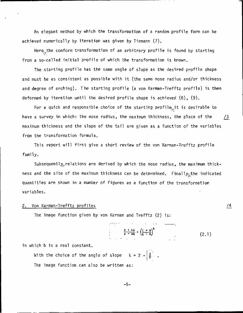
2. Von Karman-Trefftz profiles /!
The image function given by von Karman and Trefftz (2) is:
t+b\ k
( (2.1)
in which b is a real constant.I "'/
With the choice of the angle of slope k = 2 -||i .
The image function can also be written as:
-5-
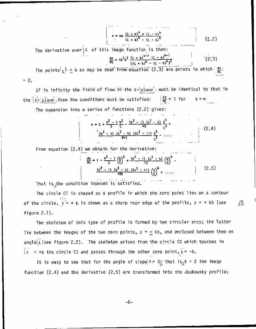
hfa (C* b)k+ (C - b)'
(C + b)k - (C - b)1 (2.2)
The derivative over of this image function is then:- b)
k"1
K 2b) - (C - b)]
The points'?,- +_ b as may be seen from -equation (2.3) are points in which '
= 0.
If in infinity the field of flow, iii-the z-|plane; - must be identical to that in
the i '-'pLine \ than the conditions must be satisfied: iaf'= 1 for c +-•- -^>- i r_i - — •
The expansion into a series of functions (2.2) gives:
x - Ck2- 1 b2 (k2 - 1) (k2 - V b4__ j_ _
(k2 - 1) (k2 - 4) (2k2 - 11) b6 _(2.4)
From equation (2.4) we obtain for the derivative:
dz k2 -15
(k2 - 1) (k2 - U) (2k2 - 11)F33
(2.5)
That isrthe condition imposed is satisfied.
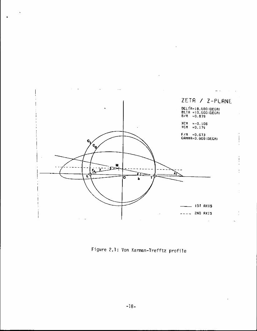
The circle Cl is shaped as a profile in which the zero point lies on a contouri~~-i
of the circle,<c= + b is shown as a sharp rear edge of the profile, z = + kb (see
figure 2.1).
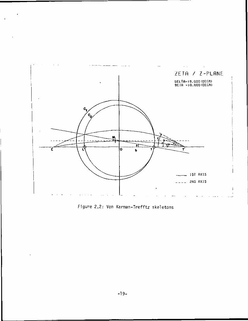
The skeleton of this type of profile is formed by two circular arcs; the latter
lie between the images of the two zero points, z = +_ kb, and enclosed between them an
angle! 6 (see figure 2.2). The skeleton arises from the circle CO which touches in
U_ = +b the circle Cl and passes through the other zero point, 5= -b.
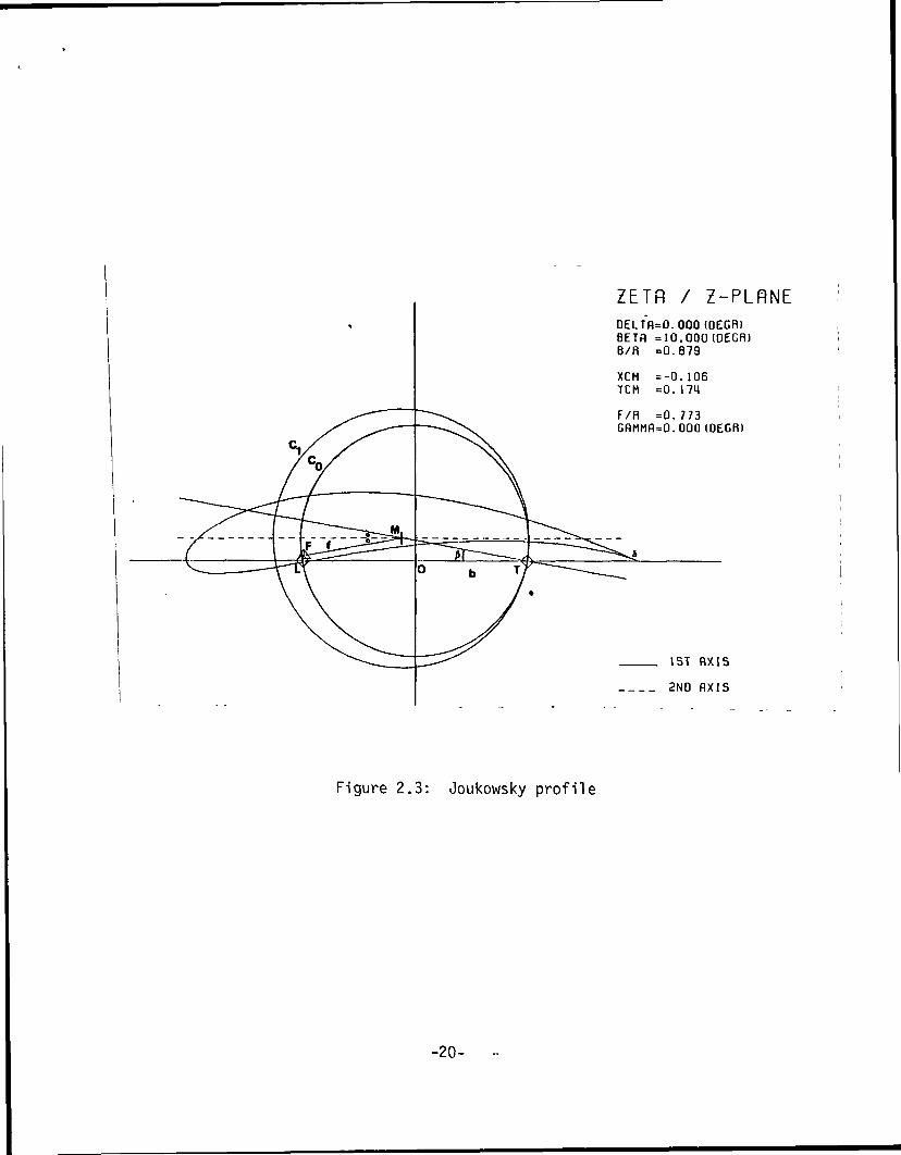
It is easy to see that for the angle of slope'«= OF that is^k = 2 the image
function (2.4) and the derivative (2.5) are transformed into the Joukowsky profile:
/5
-6-
dz
! (2.6)
(2.7)
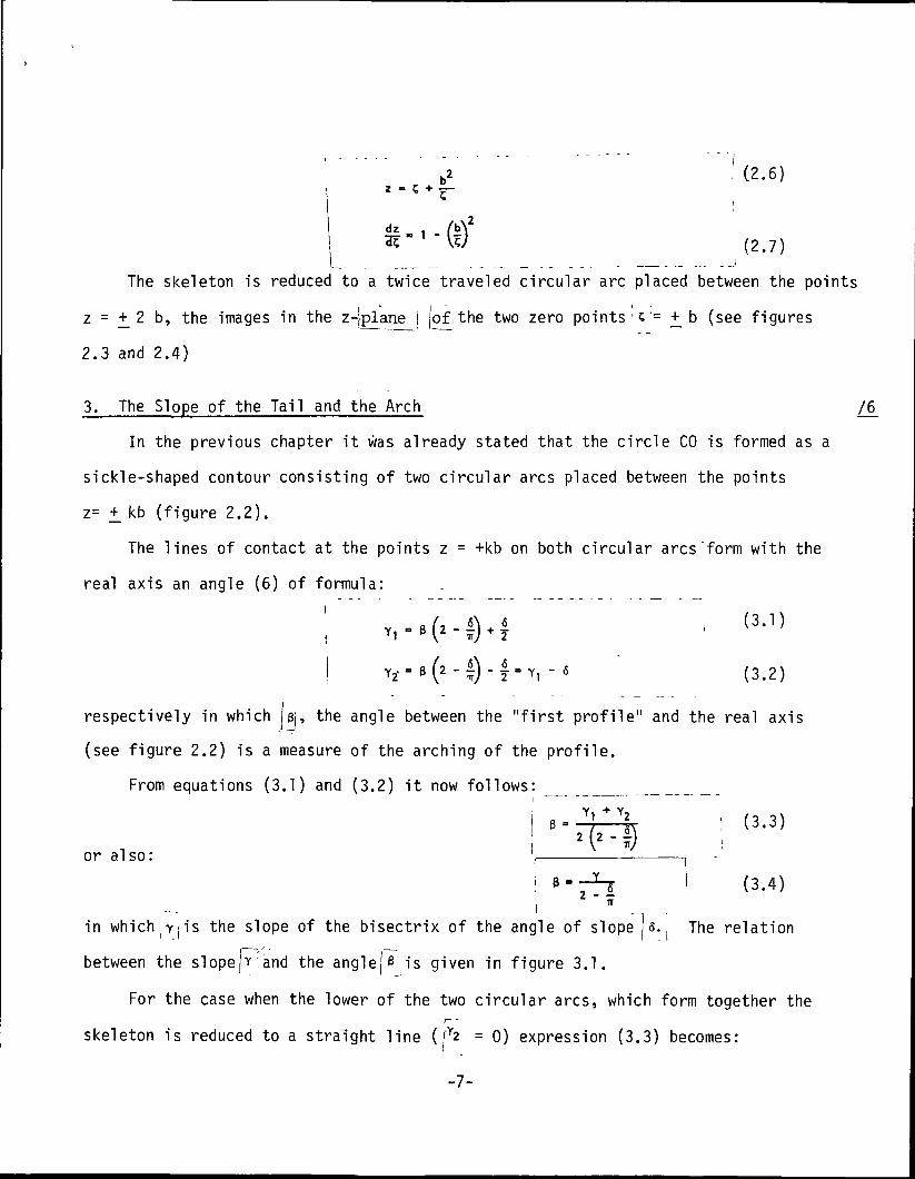
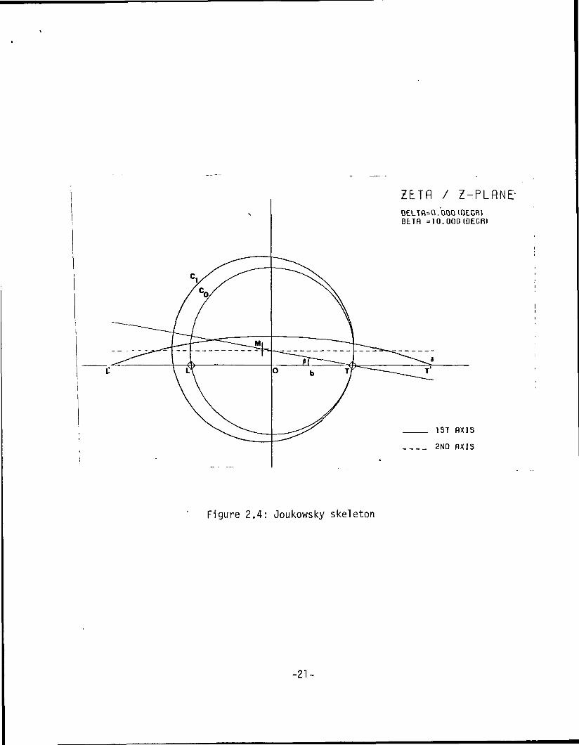
The skeleton is reduced to a twice traveled circular arc placed between the points
z = +_ 2 b, the images in the z-plane ( joflthe two zero points c = +_ b (see figures
2.3 and 2.4)
3. The Slope of the Tail and the Arch 76
In the previous chapter it was already stated that the circle CO is formed as a
sickle-shaped contour consisting of two circular arcs placed between the points
z= +_ kb (figure 2.2).
The lines of contact at the points z = +kb on both circular arcs"form with the
real axis an angle (6) of formula:
• (3J)
('-£)-! ,- 6 (3.2)
respectively in which jej, the angle between the "first profile" and the real axis
(see figure 2.2) is a measure of the arching of the profile.
From equations (3.1) and (3.2) it now follows:
or also:
in which the slope of the bisectrix of the angle of slope
(3.3)
(3.4)
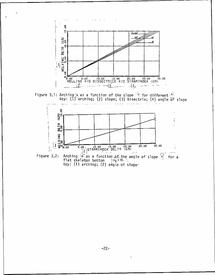
6., The relation
between the slope Y'and the anglej6 is given in figure 3.1.
For the case when the lower of the two circular arcs, which form together thej—•-
skeleton is reduced to a straight line ([Y2 = 0) expression (3.3) becomes:
-7-
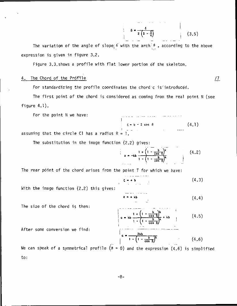
"FD (3.5)
The variation of the angle of slope's with the arch : B , according to the above
expression is given in figure 3.2.
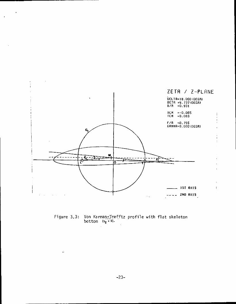
Figure 3.3.shows a profile with flat lower portion of the skeleton.
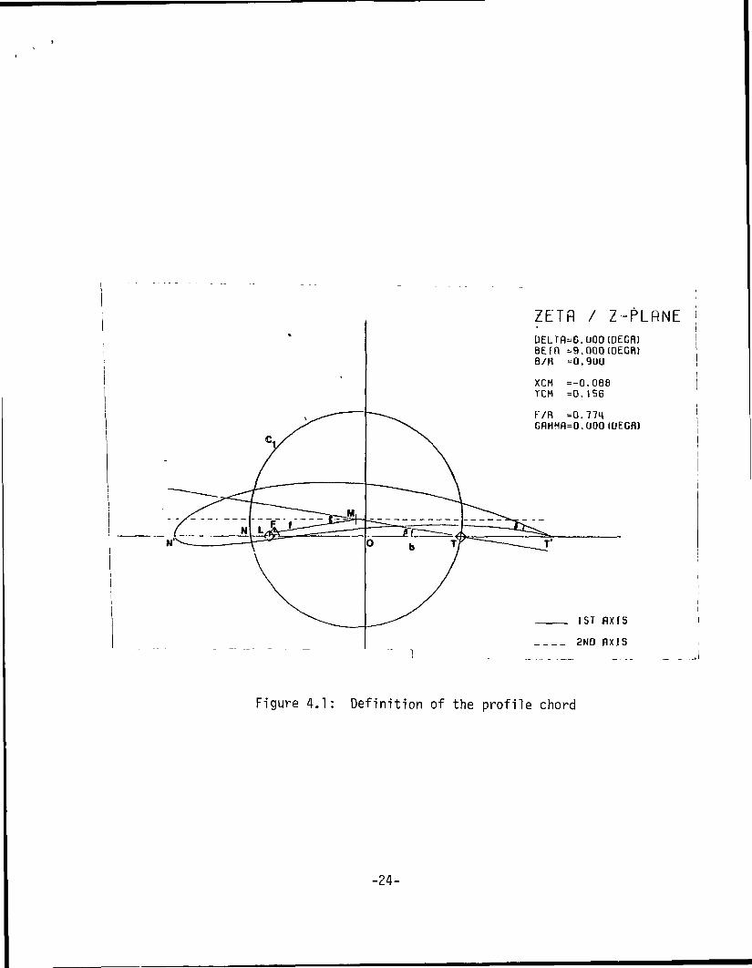
4. The Chord of the Profile /7_
For standardizing the profile coordinates the chord c is-'introduced.
The first point of the chord is considered as coming from the real point N (see
figure 4.1).
For the point N we have:
j c= b - 2 cos B (4.1 )i . ..
assuming that the circle Cl has a radius R = 1.
The substitution in the image function (2.2) gives:
With the image function (2.2) this gives:
The size of the chord is then:
After some conversion we find:
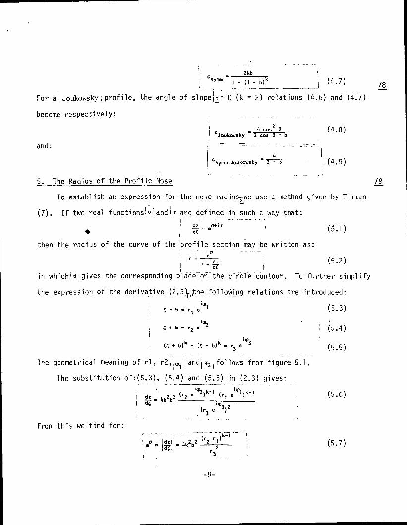
We can speak of a symmetrical profile (!e = 0) and the expression (4.6) is simplified
to:
1 * /'i b >i LL V <^z • kb - ) b Nk
1 " y cos ej
(4.2)
J
e point T for which we have:
i C - + b
z • + kb
/ u \u '
' " \ cos $/
2kb
1 - fl - M"\ cos By
(4.3)
(4.4)
(4.5)
1 (4.6)
-8-
I C2kb
symm 1 - (1 - b)k (4.7)/8
For a Joukowsky ; profile, the angle of slope||= 0 (k = 2) relations (4.6) and (4.7)
become respectively: _
! c - * cos2 B (4.8)' Joukowsky 2 cos B - bIand: r _ - . - . - - _-_-_-------
tCsymm.Joukowsky 2 - b (4.9)
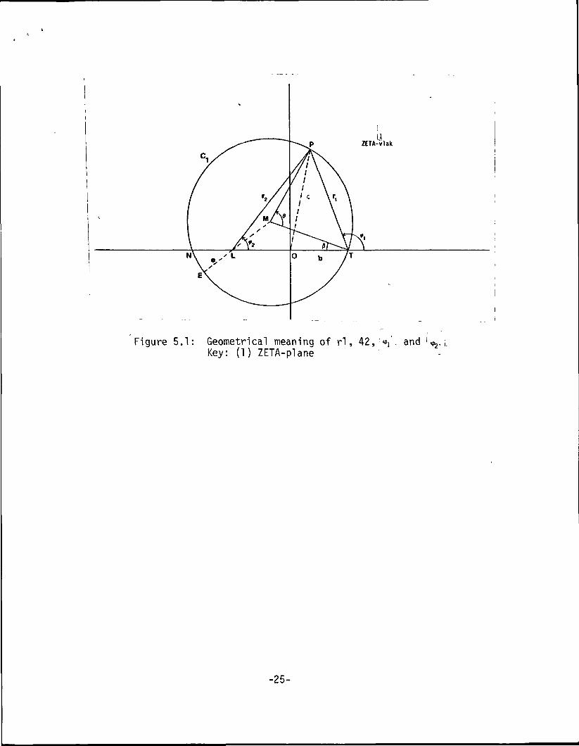
5. The Radius of the Profile Nose /9
To establish an expression for the nose radius-we use a method given by Timman
(7). If two real functions!0!and \ T iare defined in such a way that:
4l = e°+iT • (r, i)t i dc v >> • i;
then the radius of the curve of the profile section may be written as:r"^S ; <5-2)
in whichie gives the corresponding placeTon the circle contour. To further simplify
the expression of the derivative (2.31- the following relations ar^ introduced:up,
(? + b)k - (C - b)k = r3 e""3
(5.3)
(5.4)
(5.5)
The geometrical meaning of rl, r2,[ 7 and" follows from figure 5.1.i ' i — '
The substitution of:(5.3), (5.4) and (5.5) in (2.3) gives:
dz _ i, ,.2. 2 *r2, Kl(r, e } (5.6)
,(r3e
up,
From this we find for:"xk-1
(5.7)
-9-
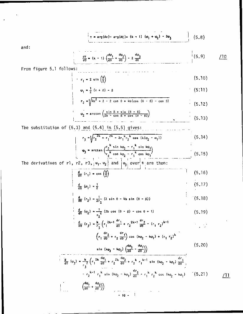
|T » arg(dz)- arg(dc)- (k - 1) (tp, + tpj)i ,
and:
From figure 5.1 follows:
r, - 2 sin If
= (n + 9) -
+ 2-2 cos 9 + 4b(cos (9 - 6) - cos 0)
sin B * sin (9 "6)
i *2 ' arctan V2b - cos B + cos (9 -
The substitution of (5.3)_and (5.4)_ij |5.5) g^ves:
2k I k kr] - 2r^ r^ cos
k k/r. sin kip. - r. sin ktp.\= arctan f-£- i L L)
'2 cos k<p2 - i-j cos kip^
The derivatives of rl, r2, r3 , ,w r v 2 \
i a /_
<P3; overj e; are then:
cos
27~ (2 sin 6 - 4b sin (8 - 6))
(tP2) " — ]-j (2b cos (8 - 6) - cos 8 + 1)
(5.8)
i' (5 .9) /IP
J
(5.10)
(5:11)
(5.12)
(5.13)
(5.14)
(5.15)
(5.16)
(5.17)
'(5.18)
(5.19)
VI
sin
r2 B9~ cos (ktp2 -
/dtp. d«p.
r2
)
(5.20)
r3
dip.
"
dr.
~ r2 r jK s i n (kip2 - k(p^)
>, ^
^2 . r ic5e~ i cos (kip2 - fop,) '(5.21)
- 10 -
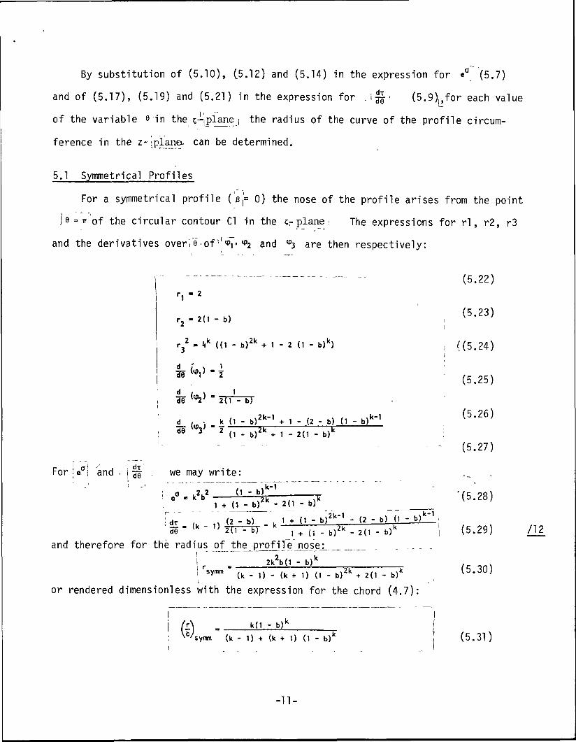
By substitution of (5.10), (5.12) and (5.14) in the expression for e° (5.7)
and of (5.17), (5.19) and (5.21) in the expression for . i • (5.9),,for each valueL-
of the variable e in the'c-j-jplanej the radius of the curve of the profile circum-
ference in the z-J plane can be determined.
5.1 Symmetrical Profiles
For a symmetrical profile ( ej= 0) the nose of the profile arises from the point
je = n- of the circular contour Cl in the cr plane \ The expressions for rl, r2, r3
and the derivatives over! e of'•'<or <PZ and ^3 are then respectively:
_. (5>22)
r,- 2 ( 1 - 5 ) , (5>
* i
r 2 - 4k ((1 - b)2k + 1 - 2 (1 - b)k) . ((5.i
d /' v 1 '-fS Up.) • -~\ d9 . ' 2 (5.
d («L) - 'd8 "T 2(1 - b)
2k 1 k-1 (5.d / • k (1 - br + 1 - (2 - b) (1 - b)K
de 3 2 (i - b)2k + i - 2(1 - b)k :
- - - - - (5.
For 'e° j and . \ -^ ' . we may write:
! T ,'i2 n " b) -i '(r.! fe "ku , * d - b)'k - 20 - b)k (j-
! Jr <•> - ^ 1 + (1 - b)214"1 - (2 - b) (1 - b)k'J' 51 - (k - 1) l) . ^) " k 2k \k 1 (5
and therefore for the radius of the profile nose: _2k2b(l - b)k
symm , .\ ,, ,, ,, . v 2 k ,. .\ (5.
23)
24)
25)
26)
27)
28)
29) 712
30)
or rendered dimensionless with the expression for the chord (4.7)
I '
fc'synm (k - 1) + (k + 1) (1 - fa/ (5.31)
-11-
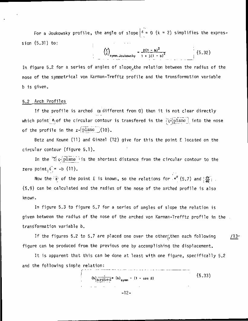
For a Joukowsky profile, the angle of slope 6 = 0 (k = 2) simplifies the expres-
sion (5.31) to: ,(l) „ 2(1 - b)2 ,g 32v^C/symm. Joukowsky 1 + 3 ( 1 - b)2 j
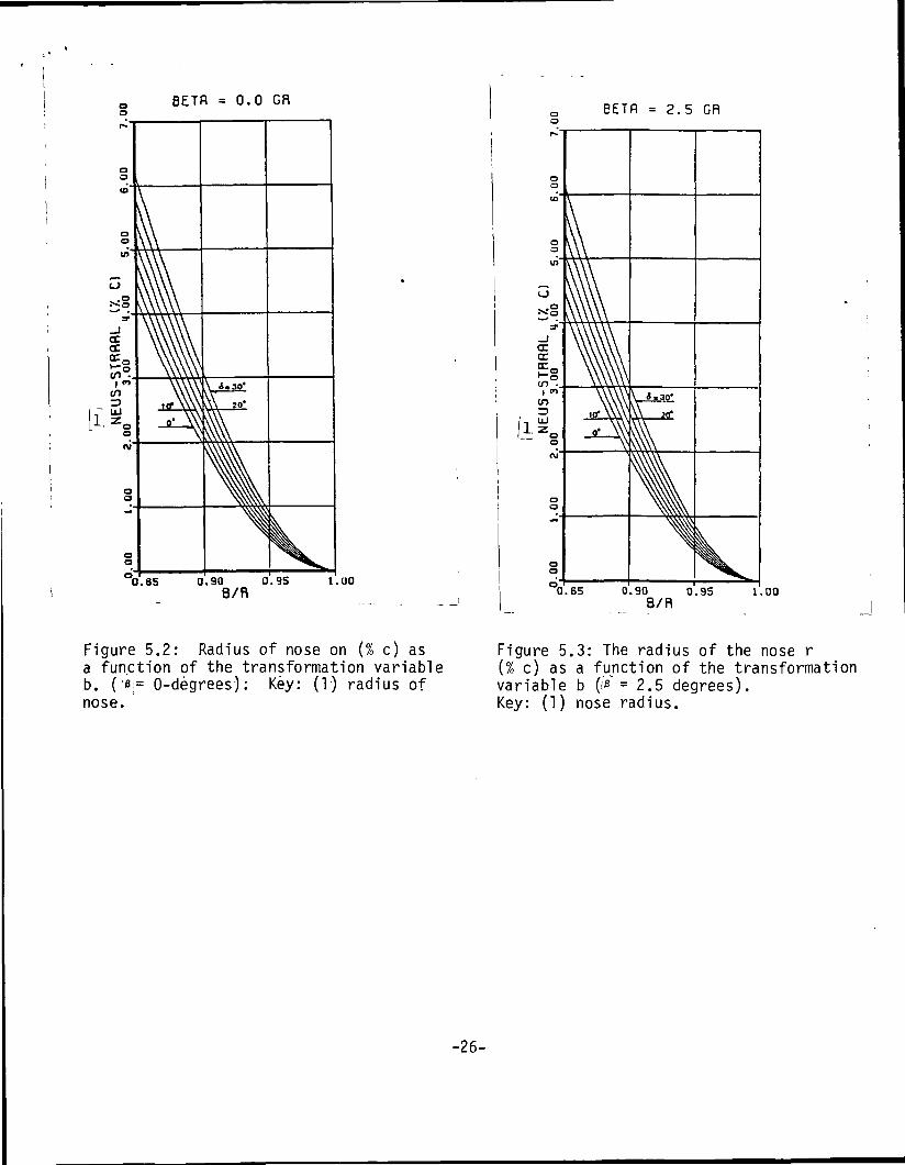
In figure 5.2 for a series of angles of slopeuthe relation between the radius of the
nose of the symmetrical von Karman-Trefftz profile and the transformation variable
b is given.
5.2 Arch Profiles
If the profile is arched (B different from 0) then it is not clear directly
which point| 9(0f the circular contour is transfered in the u-jpianej into the nose
of the profile in the z-| plane _J(10).
Betz and Keune (11) and Ginzel (12) give for this the point E located on the
circular contour (figure 5.1).
In the 'T[ c-[plane i is the shortest distance from the circular contour to the
zero point !<r= -b (11 ).i* *
Now the To' of the point E is known, so the relations for i ea (5.7) and j|l"| .
(5.9) can be calculated and the radius of the nose of the arched profile is also
known.
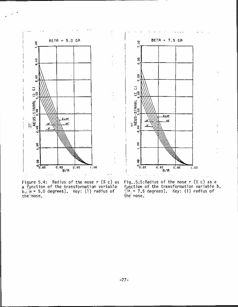
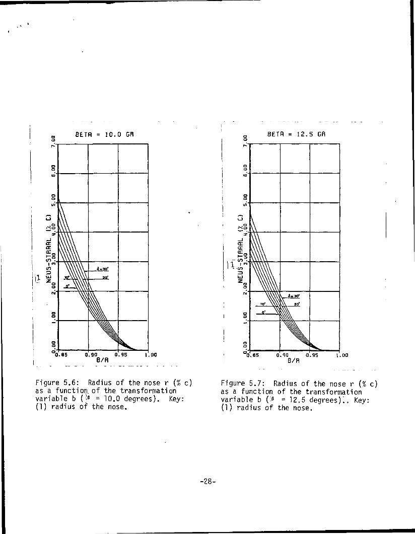
In figure 5.3 to figure 5.7 for a series of angles of slope the relation is
given between the radius of the nose of the arched von Karman-Trefftz profile in the .
transformation variable b.
If the figures 5.2 to 5.7 are placed one over the otherrthen each following /13~
figure can be produced from the previous one by accomplishing the displacement.
It is apparent that this can be done at least with one figure, specifically 5.2
and the following simple relation:
(1 - «s 6)
-12-
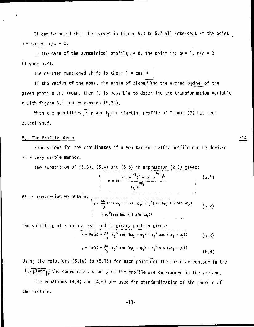
It can be noted that the curves in figure 5.3 to 5.7 all intersect at the point
b = cos, B, r/c = 0.
In the case of the symmetrical profile 6 = 0, the point is: b^= 1, r/c = 0
(figure 5.2).
The earlier mentioned shift is then: 1 = cos: B.t r I
If the radius of the nose, the angle of slope|^[and the arched [spine ;of the
given profile are known, then it is possible to determine the transformation variable
b with figure 5.2 and expression (5.33).
With the quantities 6, e and brjthe starting profile of Timman (7) has been
established.
6. The Profile Shape /14
Expressions for the coordinates of a von Karman-Trefftz profile can be derived
in a very simple manner.
The substition of (5.3), (5.4) and (5.5) in expression (2.2) gives:I iw? i '<P< i
,r3e
After conversion we obtain:z = — (cos tfl, - i sin <pj (r (cos \vf>2 + i sin\ — —— < ^X 9 \*w —— "fo • • — - • • -~ m r ^
3 \ o • t /I.
H r^ (cos kipj + i sin kq ))
The splitting of z into a real and imaginary portion gives:
x = Re(z) = —- (r cos (lop. - (p,) + r, cos (ktp, - ip,)) If, l.\i r - ^ Z J . i ' J \ u • d /
y - lm(z) - ~ (r k sin (k<p. - (p,) + r.k sin (ktp, - «p,))3 2 3 1 1 3 (6.4)
Using the relations (5.10) to (5.15) for each pointre of the circular contour in the
i H?1^6' ^6 coordl'nates x and y of the profile are determined in the z-plane.
The equations (4.4) and (4.6) are used for standardization of the chord c of
the profile.
-13-
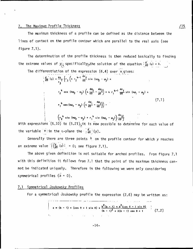
7. The Maximum Profile Thickness /15
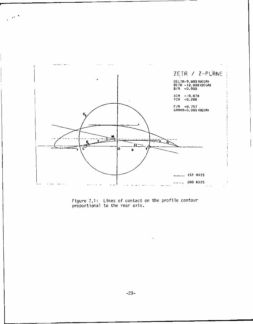
The maximum thickness of a profile can be defined as the distance between the
lines of contact on the profile contour which are parallel to the real axis (see
figure 7.1).
The determination of the profile thickness is then reduced basically to finding
the extreme values of yn specif icallyj,(the solution of the equation / f^ (y) - o. '
The differentiation of the expression (6.4) over e gives:
w < > ) = kb (r (k r k-' l!ir3
k /r2 cos (ktp2 - «p») 1
k . . /
sin (kip- " W
dip dtp xk -=. - — i)
dtp, d<p,XN
k-1 dr1* k r, ' g^i sin
(7.1), UH,1 "^X^
r," cos (k<p, - (p,) I
sin (ktp2 - «p3) -»• ri sin (ktp, - v
With expressions (5.10) to (5.21)^it is now possible to determine for each value of
the variable e ; in the c-plane the '\"ss'(y).
Generally there are three points e on the profile contour for which y reaches' 17d L >an extreme value 'j^ (y) = 0; see figure 7.1).
The above given definition is not suitable for arched profiles. From figure 7.1
with this definition it follows from 7.1 that the point of the maximum thickness can-
not be indicated uniquely. Therefore in the following we were only considering
symmetrical profiles (;e = 0).
7.1 Symmetrical Joukowsky Profiles^
For a symmetrical Joukowsky profile the expression (2.6) may be written as:
z - (b - 1) + (cos 6 + I sin 6) + t>2(b - 1) + b2(cos 6 - 1 sin 9) |(b - 1)Z + 2(b - 1) cos 9 + 1 (7.2)
-14-
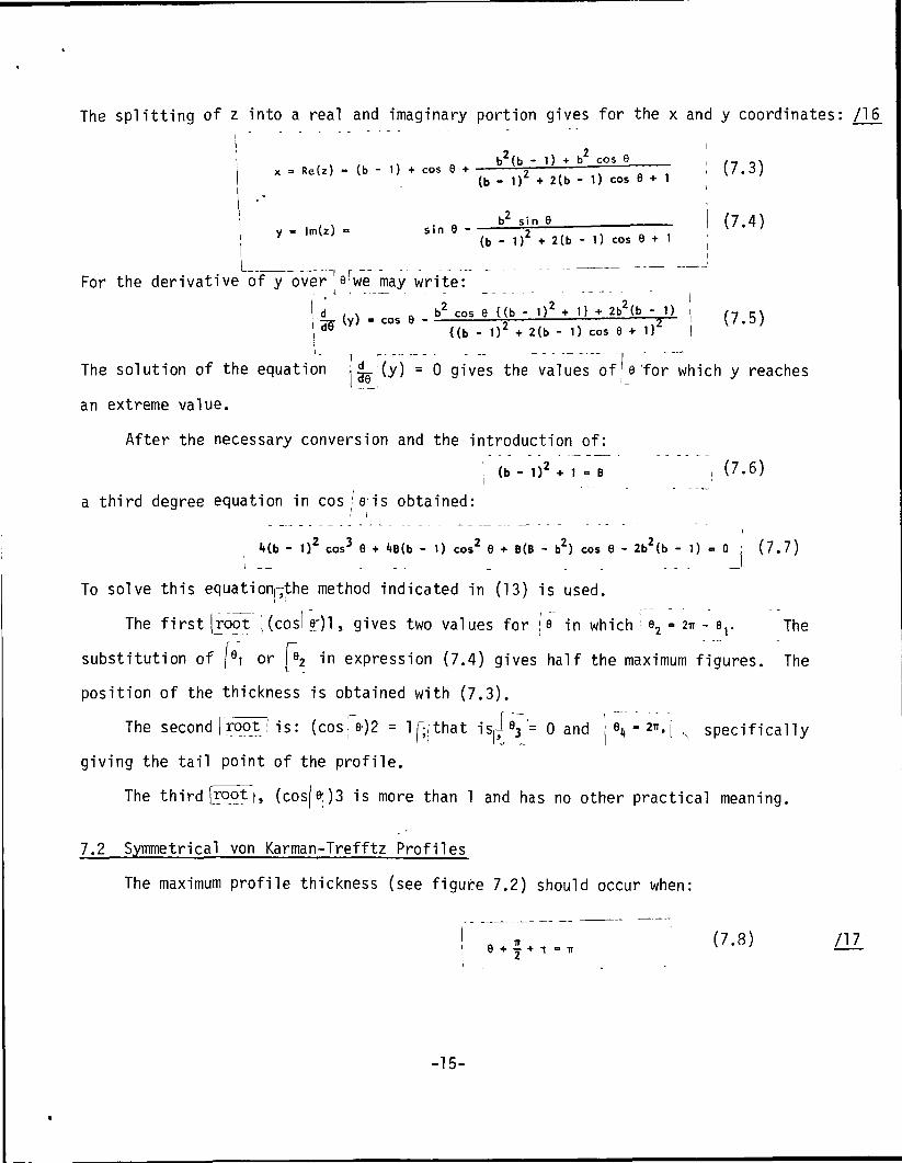
The splitting of z into a real and imaginary portion gives for the x and y coordinates: /1 6
, 2b (b - 1) + b cos 9 _ , .
2 , (7.3)
b2 sin 6y = lm(z) = sin 6 7 ,y (b - 1) + 2(b - 1) eos 6 + 1
i
(7.4)
For the derivative of y overawe may write:
-TX (y) = cos 6 £25 ± —— 3— i (7.5)d9 {(b - 1) + 2(b - 1) cos 6 + 1 } I
i
The solution of the equation ; £_ (y) = 0 gives the values ofje'for which y reachesI , —
an extreme value.
After the necessary conversion and the introduction of:
j (b - I)2 + 1 - B | (7.6)
a third degree equation in cos le is obtained:
Mb - D2 cos3 9 + l»B(b - 1) cos2 9 + B(B - b2) cos 6 - 2b2(b - 1) = 0 : (7.7)
To solve this equation^the method indicated in (13) is used.
The first |rop ] (cosl e;)l, gives two values for | e in which ! e2 = 2* - er The
substitution of |9i or JV in expression (7.4) gives half the maximum figures. The
position of the thickness is obtained with (7.3).
The second | root_i is: (cos|e-)2 = Ijyithat is^e3 '= 0 and : e4 - 2*. j , specifically
giving the tail point of the profile.
The third (rooFf, (cos|e;)3 is more than 1 and has no other practical meaning.
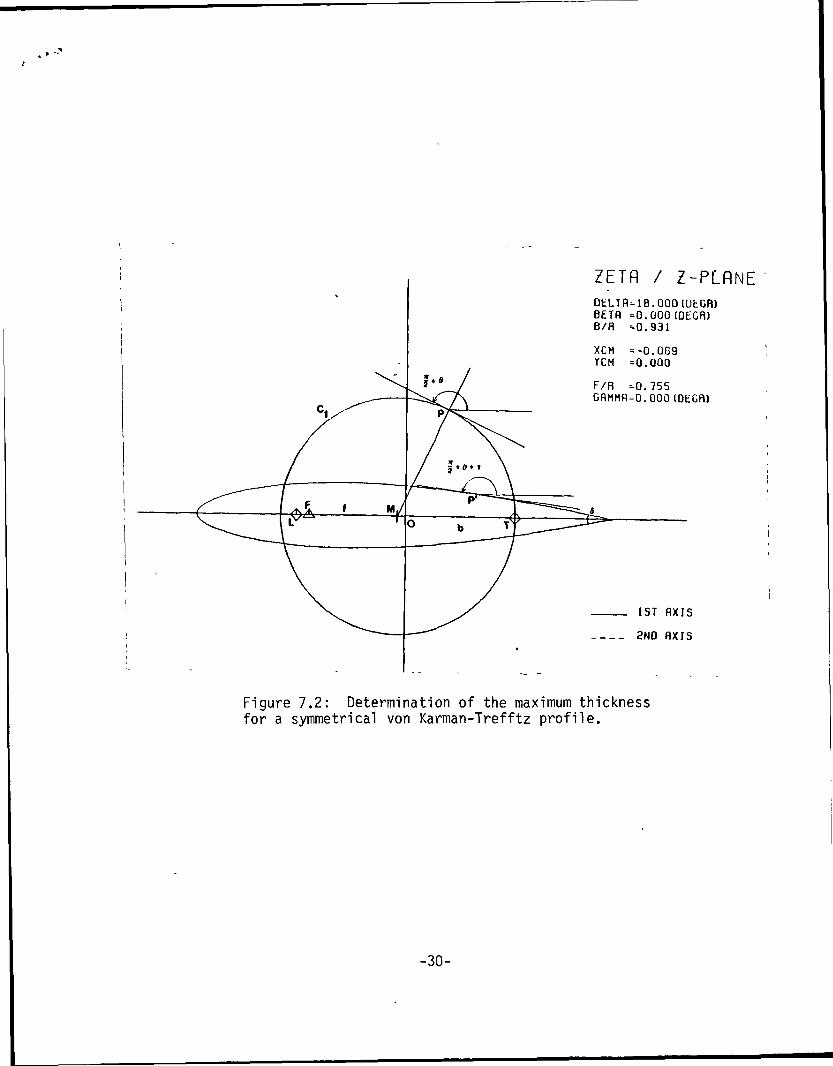
7.2 Symmetrical von Karman-Trefftz Profiles
The maximum profile thickness (see figure 7.2) should occur when:
-15-
The substitution of the expression for (5.8) in the above relation gives:
(7 9)+ j + (k - i) (tp2 -up,) - 2ip3 = TT
in which! <P,, <P2I and <P3|are functions of 9|(see specifically the relations (5.11),
(5.13) and (5.15)).
The value of jj*j which satisfies the requirements formulated in (7.9) is found
by means of an iteration process.
The substitution of the fejcalculated by this means in expression (6.4) gives
half the maximum profile thickness. The position of the maximum thickness is
obtained with equation (6.3).
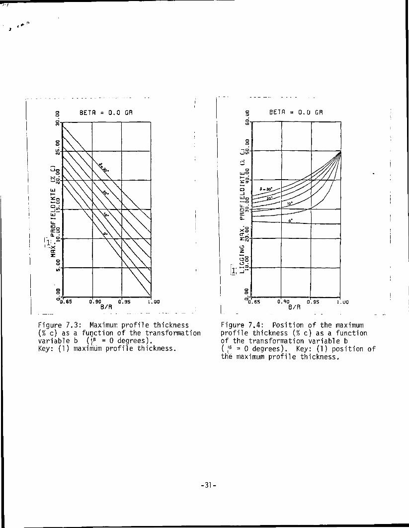
Figures 7.3 and 7.4 give for a series of angle of slope the maximum profile
thickness (in percentage c) and the position of the maximum thickness of the function
of the transformation variable b.
8. Literature /18
1. Joukowsky, N.; On the Contours of the Carrier Surfaces of the Hang Glider.
ZFM 1, page 281 to 284 (1910). ZFM 3, page 81 to 86 (1912). , •
2. Karman, Th. von, Trefftz, E., Potential Flow Around Given)Lifting Surface
Cross-Sections. ZFM 9, page 111 to 116 (1918).
3. Mises, R. von; .On the Theory of the Carrier Surface.Buoyancy. ZMF 8 pages 157
to 163 (1917). ZFM 11, pages 68 to 73, pages 87 to 89 (1920).
4. Mueller, W. On the Construction of Carrier Surface Profiles. ZAMM 4, pages 213
to 241 (1924).
5. Blom, J. J. H. Description of a Five Parameter Family of Profiles. Technical
University of Delft, Section of Aeronautical and Astronautical Technology,
Report LR-220 (1976).
-16-
10. Wolthoorn, C., Rozendal, D. A Survey of the Karman-Trefftz Profile.- Technical /19
University of Delfft, Section of Aeronautical and Astronautical Technology.
TZ Report (1968).
11. Betz, A., Keune, F. Generalized Karman-Trefftz Profiles. Aeronautic Research,
Volume 13, page 336 jtoj 345 (1936).
12. Ginzel, I. Curvature Properties of Profiles. Aeronautic Research, Volume 14,
pages 573 to 576 (1937).
13. Neumark, S. Solution of cubic and quartic equations.
Pergamon Press Ltd., London (1965).
-17-
ZETfl / Z-PLflNE.DELffi=18.GOO(DEGR)BETfl =10.000(DEGR)B/R -0.879
XCM =-0.106TCM =0 .174
F/R =0.073GflMMR=0.000 (OEGR)
1ST flXIS
2ND flXIS
Figure 2.1: Von Karman-Trefftz profile
-18-
ZETfl / Z-PLflNEOELTR=18.0001DEGR)BEffi =10.000lDEGfl)
1ST HXIS
__ 2ND flXIS
Figure 2.2: Von Karman-Trefftz skeletons
-19-
ZETfl / Z-PLflNEDELffl=0.000(DECR)BETfl =10.000 (DEGR)B/R =0.879
XCM =-0.106YCM =0.174
F/R =0.773GRMMfl=0.000(OEGR)
1ST flXIS
2ND flXIS
Figure 2.3: Joukowsky profile
-20-
ZETfl / Z-PLRNE-
BtTfl =10.000(OEGR)
1ST HXIS
_ 2ND flXIS
Figure 2.4: Joukowsky skeleton
-21-
<X"I—LU
S*< _m
UJ
0.00 5.00HELLING V/D
•X*
S .30'
10.00 15.00 20.00 25.00 30.00BISSECTRICE V/D STRflRTHOEK (GR)
Figure 3.1: Arching |B; as a function of the slope ''Yi for differentKey: (1) arching; (2) slope; (3) bisectrix; (4) angle of slope
o.oo J.OO 15.00 20.00isrqqRTHGEK oELiq
25. QO 30.00
Figure 3.2: Arching i«]~as a function.Af_.the angle of slope |«| for aflat skeleton bottom (YZ • o>. iKey: (1) arching; (2) angle of slope-
-22-
ZETfl / Z-PLRNEQELTfl=18.000(OEGR)BETfl =H.737(DEGR)B/R =0.931
XCM =-0.065TCM =0.083
F/fl =0.755GflMMR=0.000(DEGR)
1ST flXIS
2ND flXIS
Figure 3.3: Von Karmarnjrefftz profile with flat skeletonbottom (i2 • °>-
-23-
ZETf l / Z-PLRNE jUELTFN6.000(DEGR) jBEFfl =-9.000(OEGB) !B/R =0.900 !
XCM =-0.088 IYCM =0.156
iF/R =0.7714 !GflMMfl=O.UOO(UEGR)
1ST flXIS
2ND flXIS
Figure 4.1: Definition of the profile chord
-24-
IIZETA-vlak
Figure 5.1: Geometrical meaning of rl, 42, :<*i • andKey: (1) ZETA-plane
-25-
BETfl = 0.0 GRBETfl = 2.5 GR
u.o
croc
en
o:(X
1
.65 0.90 0.95 l.UOB/R 0.65 0.90
B/R0.95 1.00
Figure 5.2: Radius of nose on (% c) asa function of the transformation variableb. ( B;= 0-degrees): Key: (V) radius ofnose.
Figure 5.3: The radius of the nose r(% c) as a function of the transformationvariable b Oe = 2.5 degrees).Key: (1) nose radius.
-26-
BETfl = 5.0 GR
crcrEEoen0.,i mCO
UJzo
01
.85 0.90 0.95B/R
ao
BETR = 7.5 GR
<x(X
ICO
l .UO °0.8S 0.90
B/R0.95 l .UO
Figure 5.4: Radius of the nose r (% c) asa function of the transformation variableb.i (8 = 5.0 degrees). Key: (1) radius ofthe'-'n'ose.
Fig.,5:5:Radius of the nose r (% c) as afunction of the transformation variable b.''P6",= 7.5 degrees). Key: (1) radius ofthe nose.
-27-
BETfl = 10.0 GR
a:a:
ICO
11 «
0.85 0 90B/R
0.95
oo
BETfl = 12.5 GR
cr<r
1 i <•»'- in
1.00 65 0.90
B/R0.95 I 00
Figure 5.6: Radius of the nose r (% c)as a function, of the transformationvariable b (|B = 10.0 degrees). Key:(1) radius of the nose.
Figure 5.7: Radius of the nose r (% c)as a function, of the transformationvariable b (;.B = 12.5 degrees).. Key:(1) radius of the nose.
-28-
ZETfl / Z-PL'flNEDELTfl-.9.UOO([JEGR)BETfl =-12.000(DEGR)B/R -0.900
XCM =--0.078YCM =0.208
F/R =0.757GflMMfl-O.OOO(DEGR)
IST axis
2ND flXIS
Figure 7.1: Lines of contact on the profile contourproportional to the rear axis.
-29-
ZETfl / Z-PLflNEDELTfl-lS.OOOIOtGR)BETH =0.000(OECR)B/R -0.931
XCM =-0.069 IYCM =0.000
F/R -0.755GflMMfl = 0.000 (DEGR)
1ST flXIS
2ND flXIS
Figure 7.2: Determination of the maximum thicknessfor a symmetrical von Karman-Trefftz profile.
-30-
oo BETH = 0.0 GR
Ooo
l1'-—x
"0.6S 0.90B/R
0.95
BETfl = 0.0 GR
i.oo a 65 0.90B/R
0.95 l.UO
Figure 7.3: Maximum profile thickness(% c) as a function of the transformationvariable b (|8' = 0 degrees).Key: (1) maximum profile thickness.
Figure 7.4: Position of the maximumprofile thickness (% c) as a functionof the transformation variable b( I6 = 0 degrees). Key: (1) position ofthe maximum profile thickness.
-31-