
Montagebeschrijving - produktinfo.conrad.com · Montagebeschrijving Assembly instructions Ontdek...
33
Montagebeschrijving Assembly instructions Ontdek wat er onder de motorkap van een Porsche 911 zit! Explore the technology of a Porsche 911 engine.
Transcript of Montagebeschrijving - produktinfo.conrad.com · Montagebeschrijving Assembly instructions Ontdek...

Montagebeschrijving
Assembly instructions
Ontdek wat er onder de motorkap van een Porsche 911 zit!
Explore the technology of a Porsche 911 engine.
© 2016 Franzis Verlag GmbH, 85540 Haar bei München © 2016 Franzis Verlag GmbH, 85540 Haar bei München
Alle rechten voorbehouden, waaronder rechten op fotomechanische reproductie en op de opslag in elektronische media. Het maken en verspreiden van kopieën op papier, op gegevensdragers of via het internet, in het bijzonder als PDF, is uitsluitend toegestaan met uitdrukkelijke toestemming van de uitgever en wordt in alle andere gevallen strafrechtelijk vervolgd.
All rights reserved, including those of reprinting, reproduction and storage in electronical media. No part may be reproduced and distributed on paper, on storage media, or in the Internet, especially as PDF, without the publishers prior written permission. Any attempt may be prosecuted.
De meeste productnamen, bedrijfsnamen en bedrijfslogo's die in dit document staan, zijn geregistreerde handelsmerken en dienen als zodanig te worden behandeld. De uitgever volgt bij de productnamen doorgaans de spelling van de fabrikant.
As a general rule, most of the product names, company names and company logos used in this book are registered trademarks and have to be treated as such. In general, the publishing company uses the spelling of the respective producers.
Alle in dit document opgenomen montagebeschrijvingen en tips zijn met de grootst mogelijke zorgvuldigheid ontwikkeld, gecontroleerd en getest. Desondanks is het niet uit te sluiten dat het document of het bouwpakket fouten bevat. De uitgever en de auteur zijn uitsluitend in geval van opzettelijk verzuim of bij grove nalatigheid aansprakelijk te stellen. Voor andere gevallen zijn de uitgever en de auteur uitsluitend aansprakelijk conform de wet op de productaansprakelijkheid wanneer er verlies van leven of lichamelijk letsel optreedt, alsmede bij opzettelijke overtreding van essentiële contractbepalingen. Schadevergoedingen voor overtredingen van essentiële contractbepalingen beperken zich tot de voor dergelijke contracten voorzienbare schade, voor zover de wettelijke productaansprakelijkheid niet anders voorschrijft.
All assembly instructions and tips in this book have been developed, verified and tested with utmost care. However, errors in the book and in the assembly kit cannot be ruled out. According to applicable laws, the publishing company and the author can be held responsible only in the case of intent or gross negligence. According to the Product Liability Act, publishing company and author are only liable for loss of life, physical injuries and damages to health or in the case of culpable violations of essential contractual obligations. The claim for damages due to violations of essential contractual obligations is limited to foreseeable damages typically associated with publishing houses, except in the case of mandatory liability according to the Product Liability Act.
Beste klanten Dit product is geproduceerd in overeenstemming met de daarvoor geldende Europese richtlijnen en is daarom voorzien van een CE-markering. Het doelmatige gebruik staat in de meegeleverde handleiding. Bij elk ander gebruik van het product en bij het aanbrengen van wijzigingen aan het product, bent u zelf verantwoordelijk voor het naleven van de geldende regels. Monteer het product daarom exact volgens de aanwijzingen in de handleiding. Dit product mag uitsluitend in combinatie met deze handleiding worden doorgegeven.
Dear customers! This product was developed in compliance with the applicable European directives and therefore carries the CE mark. Its authorized use is described in the instructions enclosed with it. In the event of non-conforming use or modification of the product, you will be solely responsible for complying with the applicable regulations. You should therefore take care to assemble the circuits as described in the instructions. The product may only be passed on along with the instruction and this note.
Het symbool met het kruis over de afvalbak geeft aan dat het product niet in het gewone huisvuil terecht mag komen. Breng het als elektrisch afval naar een recyclingvoorziening. Vraag uw gemeente waar u elektrische apparaten het beste kunt inleveren.
Waste electrical products should not be disposed of with household waste. Please recycle where facilities exist. Check with your local authority or retailer for recycling advice. All rights reserved, including those of reprinting, reproduction and storage in electronical media. No part may be reproduced and distributed on paper, on storage media, or in the Internet, especially as PDF, without the publishers prior written permission. Any attempt may be prosecuted. Hardware and software product names, company names, and company logos mentioned in this book are generally registered trademarks and have to be considered as such. For product names, the publisher uses mainly the spelling of the manufacturer.
Set: www.ideehoch2.de Set: www.ideehoch2.de
art & design: www.ideehoch2.de art & design: www.ideehoch2.de
ISBN 978-3-645-65911-6 ISBN 978-3-645-65911-6

Montagebeschrijving
Assembly instructions
MONTAGEBESCHRIJVING / ASSEMBLY INSTRUCTIONS
Niet-oplaadbare batterijen nooit opladen.
Kinderen mogen oplaadbare batterijen uitsluitend onder toezicht van volwassenen opladen.
Verwijder oplaadbare batterijen voor het opladen uit het model.
Gebruik nooit verschillende soorten batterijen door elkaar, combineer gebruikte batterijen niet met nieuwe.
Let bij het plaatsen van de batterijen op de juiste polariteit.
Haal lege batterijen uit het apparaat.
Tussen de aansluitingen mag geen kortsluiting ontstaan.
Verwijzingen naar de linker en rechter zijde van de motor zijn gezien vanuit de kant waar de ventilator zit. De cilinders 1 t/m 3 bevinden zich aan de linkerzijde van de motor, de cilinders 4 t/m 6 zitten rechts.
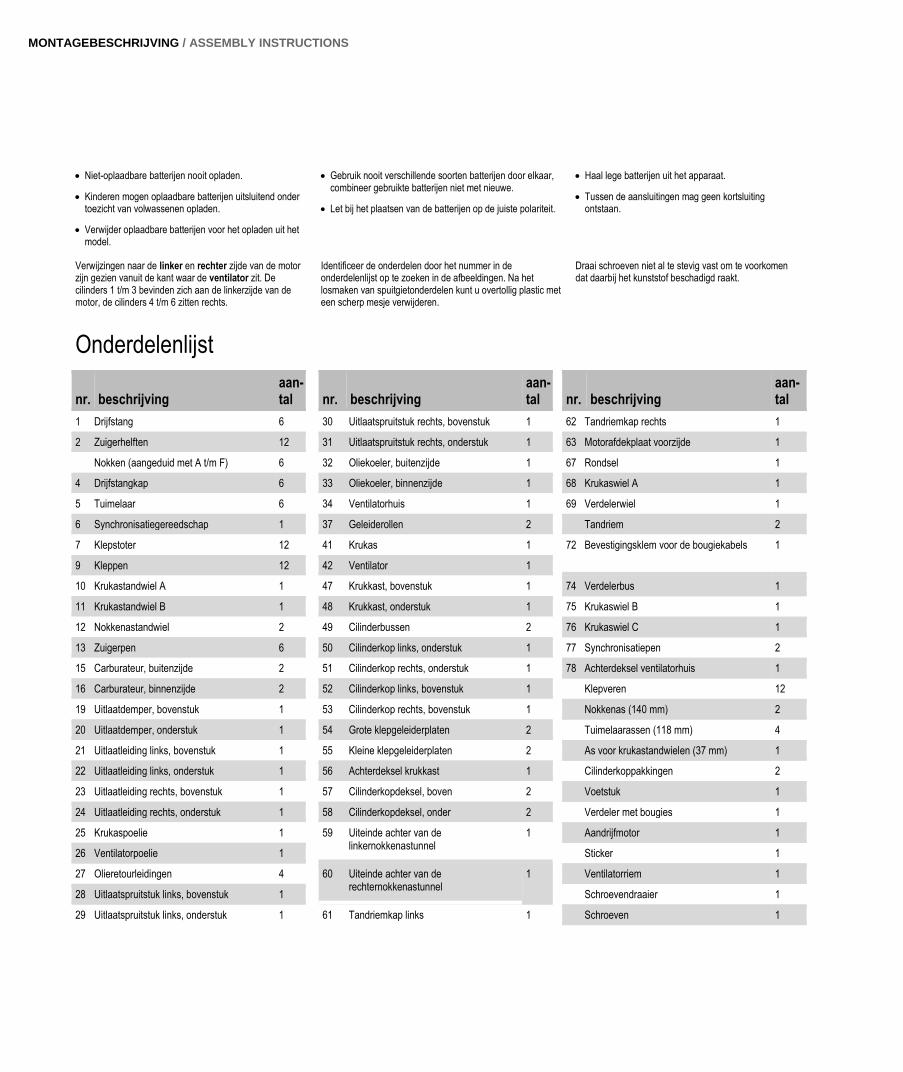
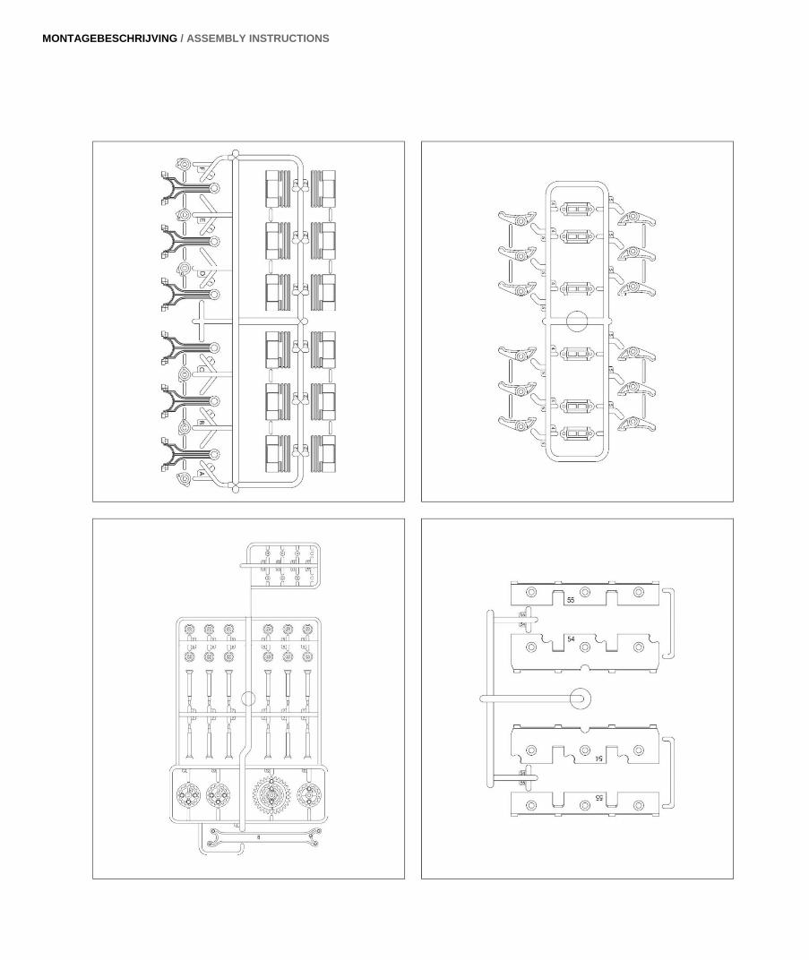
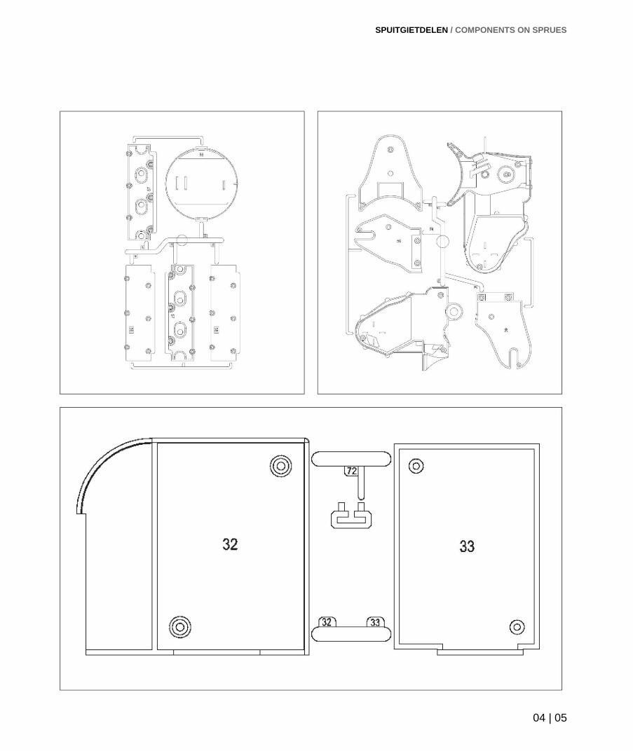
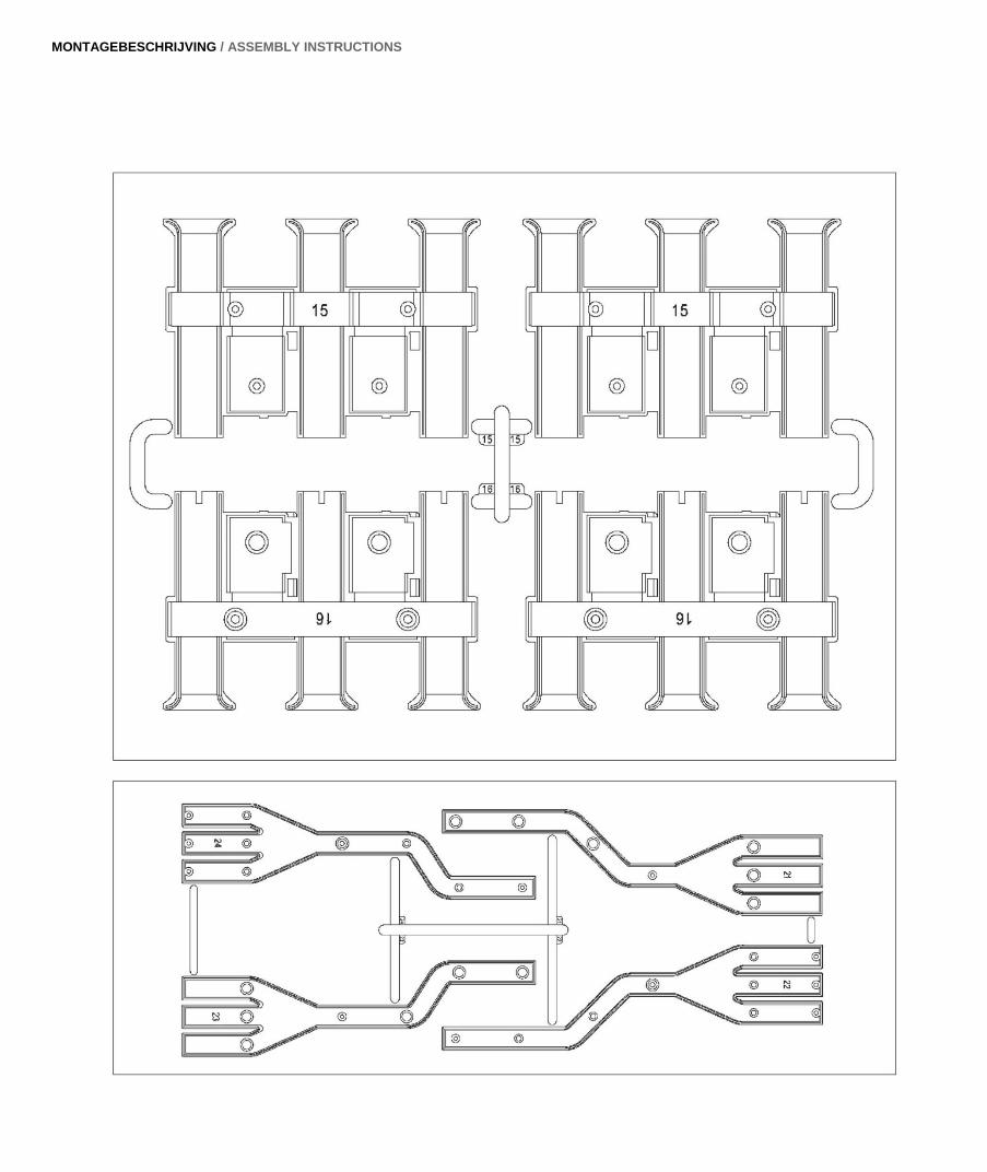
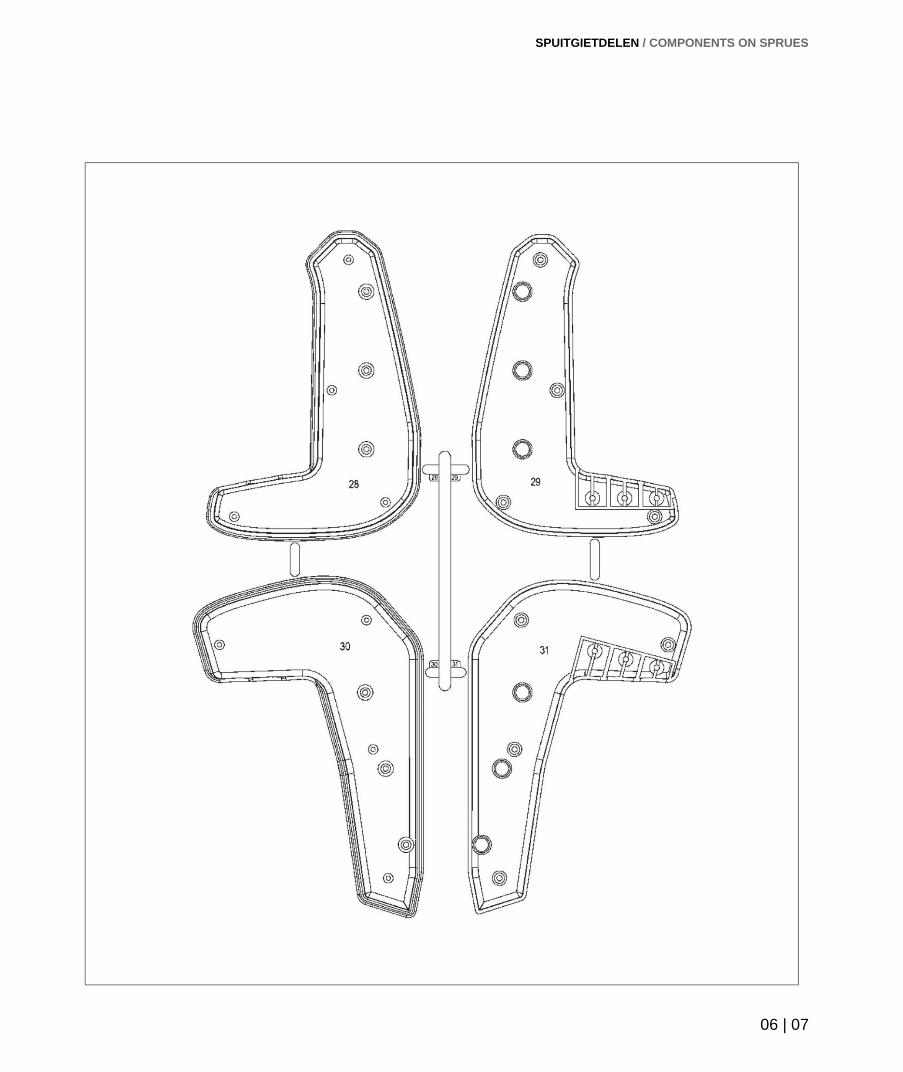
Identificeer de onderdelen door het nummer in de onderdelenlijst op te zoeken in de afbeeldingen. Na het losmaken van spuitgietonderdelen kunt u overtollig plastic met een scherp mesje verwijderen.
Draai schroeven niet al te stevig vast om te voorkomen dat daarbij het kunststof beschadigd raakt.
Onderdelenlijst
nr. beschrijving aan-tal
nr. beschrijving
aan-tal
nr. beschrijving
aan-tal
1 Drijfstang 6 30 Uitlaatspruitstuk rechts, bovenstuk 1 62 Tandriemkap rechts 1
2 Zuigerhelften 12 31 Uitlaatspruitstuk rechts, onderstuk 1 63 Motorafdekplaat voorzijde 1
Nokken (aangeduid met A t/m F) 6 32 Oliekoeler, buitenzijde 1 67 Rondsel 1
4 Drijfstangkap 6 33 Oliekoeler, binnenzijde 1 68 Krukaswiel A 1
5 Tuimelaar 6 34 Ventilatorhuis 1 69 Verdelerwiel 1
6 Synchronisatiegereedschap 1 37 Geleiderollen 2 Tandriem 2
7 Klepstoter 12 41 Krukas 1 72 Bevestigingsklem voor de bougiekabels 1
9 Kleppen 12 42 Ventilator 1
10 Krukastandwiel A 1 47 Krukkast, bovenstuk 1 74 Verdelerbus 1
11 Krukastandwiel B 1 48 Krukkast, onderstuk 1 75 Krukaswiel B 1
12 Nokkenastandwiel 2 49 Cilinderbussen 2 76 Krukaswiel C 1
13 Zuigerpen 6 50 Cilinderkop links, onderstuk 1 77 Synchronisatiepen 2
15 Carburateur, buitenzijde 2 51 Cilinderkop rechts, onderstuk 1 78 Achterdeksel ventilatorhuis 1
16 Carburateur, binnenzijde 2 52 Cilinderkop links, bovenstuk 1 Klepveren 12
19 Uitlaatdemper, bovenstuk 1 53 Cilinderkop rechts, bovenstuk 1 Nokkenas (140 mm) 2
20 Uitlaatdemper, onderstuk 1 54 Grote klepgeleiderplaten 2 Tuimelaarassen (118 mm) 4
21 Uitlaatleiding links, bovenstuk 1 55 Kleine klepgeleiderplaten 2 As voor krukastandwielen (37 mm) 1
22 Uitlaatleiding links, onderstuk 1 56 Achterdeksel krukkast 1 Cilinderkoppakkingen 2
23 Uitlaatleiding rechts, bovenstuk 1 57 Cilinderkopdeksel, boven 2 Voetstuk 1
24 Uitlaatleiding rechts, onderstuk 1 58 Cilinderkopdeksel, onder 2 Verdeler met bougies 1
25 Krukaspoelie 1 59 Uiteinde achter van de linkernokkenastunnel
1 Aandrijfmotor 1
26 Ventilatorpoelie 1 Sticker 1
27 Olieretourleidingen 4 60 Uiteinde achter van de rechternokkenastunnel
1 Ventilatorriem 1
28 Uitlaatspruitstuk links, bovenstuk 1 Schroevendraaier 1
29 Uitlaatspruitstuk links, onderstuk 1 61 Tandriemkap links 1 Schroeven 1


AANWIJZINGEN EN ADVIEZEN / ONDERDELENLIJST / NOTES AND ADVICE / PARTS LIST
02 | 03
Aanwijzingen en adviezen Notes and advice
Non-rechargeable batteries are not to be recharged.
Rechargeable batteries are only to be charged under adult supervision.
Rechargeable batteries are to be removed from the toy before being charged.
Different types of batteries or new and used batteries are not to be mixed.
Batteries are to be inserted with the correct polarity.
Exhausted batteries are to be removed from the toy.
The supply terminals are not to be short-circuited.
References to the left or right side of the engine mean the left or right side when viewed from the fan end. Cylinders 1-3 are on the left side of the engine and cylinders 4-6 are on the right.
Identify the various parts by looking at the list of components and the corresponding illustrations. Use a sharp knife to trim any excess plastic from the components after they have been removed from their carrier frames.
Take care not to over-tighten the screws as this may permanently damage the plastic.
Parts list
No. Description Qty No. Description Qty No. Description Qty
1 Connecting rod 6 29 Exhaust manifold left lower 1
62 Cam belt cover right 1
2 Piston halves 12 30 Exhaust manifold right upper 1
63 Engine cover plate 1
Cams (labelled A - F) 6 31 Exhaust manifold right lower 1
67 Drive gear 1
4 Bearing caps 6 32 Oil cooler outer 1
68 Crankshaft gear A 1
5 Rocker arms 6 33 Oil cooler inner 1
69 Distributor gear 1
6 Timing tool 1 34 Fan housing 1
Cam belt 2
7 Valve stems 12 37 Idler pulleys 2
72 Spark plug lead mounting clip 1
9 Valves 12 41 Crankshaft 1
74 Distributor bushing 1
10 Crankshaft sprocket A 1 42 Cooling fan 1
75 Crankshaft gear B 1
11 Crankshaft sprocket B 1 47 Crankcase upper 1
76 Crankshaft gear C 1
12 Camshaft sprockets 2 48 Crankcase lower 1
77 Timing alignment pins 2
13 Gudgeon (piston) pins 6 49 Cylinder barrels 2
78 Fan housing rear cover 1
15 Carburettor outer 2 50 Cylinder head left lower 1
Valve springs 12
16 Carburettor inner 2 51 Cylinder head right lower 1
Camshafts (140 mm) 2
19 Exhaust muffler upper 1 52 Cylinder head left upper 1
Rocker shafts (118 mm) 4
20 Exhaust muffler lower 1 53 Cylinder head right upper 1
Metal shaft (37 mm) 1
21 Exhaust pipe left upper 1 54 Large valve guide plates 2
Head gaskets 2
22 Exhaust pipe left lower 1 55 Small valve guide plates 2
Base 1
23 Exhaust pipe right upper 1 56 Crankcase rear 1
Distributor/spark plug assembly 1
24 Exhaust pipe right lower 1 57 Cylinder head covers upper 2
Engine 1
25 Crankshaft pulley 1 58 Cylinder head covers lower 2
Label 1
26 Fan pulley 1 59 Camshaft tunnel left rear 1
Fan drive belt 1
27 Oil return pipes 4 60 Camshaft tunnel right rear 1
Screwdriver 1
28 Exhaust manifold left upper 1 61 Cam belt cover left 1
Screws
MONTAGEBESCHRIJVING / ASSEMBLY INSTRUCTIONS
SPUITGIETDELEN / COMPONENTS ON SPRUES
04 | 05
MONTAGEBESCHRIJVING / ASSEMBLY INSTRUCTIONS
SPUITGIETDELEN / COMPONENTS ON SPRUES
06 | 07
MONTAGEBESCHRIJVING / ASSEMBLY INSTRUCTIONS
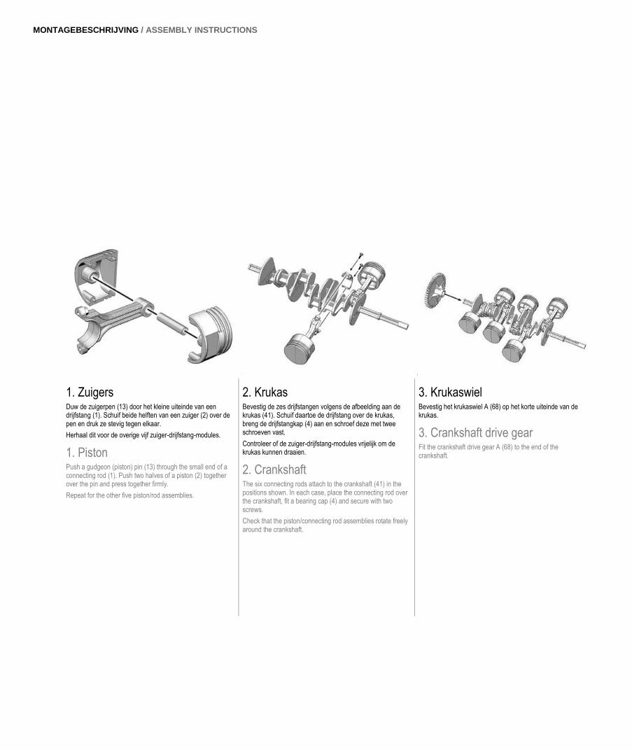
1. Zuigers Duw de zuigerpen (13) door het kleine uiteinde van een drijfstang (1). Schuif beide helften van een zuiger (2) over de pen en druk ze stevig tegen elkaar.
Herhaal dit voor de overige vijf zuiger-drijfstang-modules.
1. Piston Push a gudgeon (piston) pin (13) through the small end of a connecting rod (1). Push two halves of a piston (2) together over the pin and press together firmly.
Repeat for the other five piston/rod assemblies.
2. Krukas Bevestig de zes drijfstangen volgens de afbeelding aan de krukas (41). Schuif daartoe de drijfstang over de krukas, breng de drijfstangkap (4) aan en schroef deze met twee schroeven vast.
Controleer of de zuiger-drijfstang-modules vrijelijk om de krukas kunnen draaien.
2. Crankshaft The six connecting rods attach to the crankshaft (41) in the positions shown. In each case, place the connecting rod over the crankshaft, fit a bearing cap (4) and secure with two screws.
Check that the piston/connecting rod assemblies rotate freely around the crankshaft.
3. Krukaswiel Bevestig het krukaswiel A (68) op het korte uiteinde van de krukas.
3. Crankshaft drive gear Fit the crankshaft drive gear A (68) to the end of the crankshaft.
08 | 09
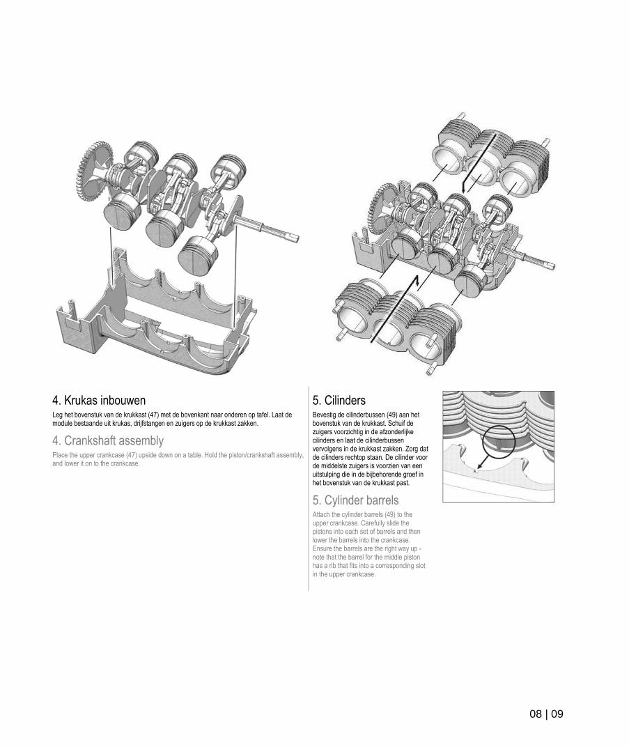
4. Krukas inbouwen Leg het bovenstuk van de krukkast (47) met de bovenkant naar onderen op tafel. Laat de module bestaande uit krukas, drijfstangen en zuigers op de krukkast zakken.
4. Crankshaft assembly Place the upper crankcase (47) upside down on a table. Hold the piston/crankshaft assembly, and lower it on to the crankcase.
5. Cilinders Bevestig de cilinderbussen (49) aan het bovenstuk van de krukkast. Schuif de zuigers voorzichtig in de afzonderlijke cilinders en laat de cilinderbussen vervolgens in de krukkast zakken. Zorg dat de cilinders rechtop staan. De cilinder voor de middelste zuigers is voorzien van een uitstulping die in de bijbehorende groef in het bovenstuk van de krukkast past.
5. Cylinder barrels Attach the cylinder barrels (49) to the upper crankcase. Carefully slide the pistons into each set of barrels and then lower the barrels into the crankcase. Ensure the barrels are the right way up - note that the barrel for the middle piston has a rib that fits into a corresponding slot in the upper crankcase.
MONTAGEBESCHRIJVING / ASSEMBLY INSTRUCTIONS
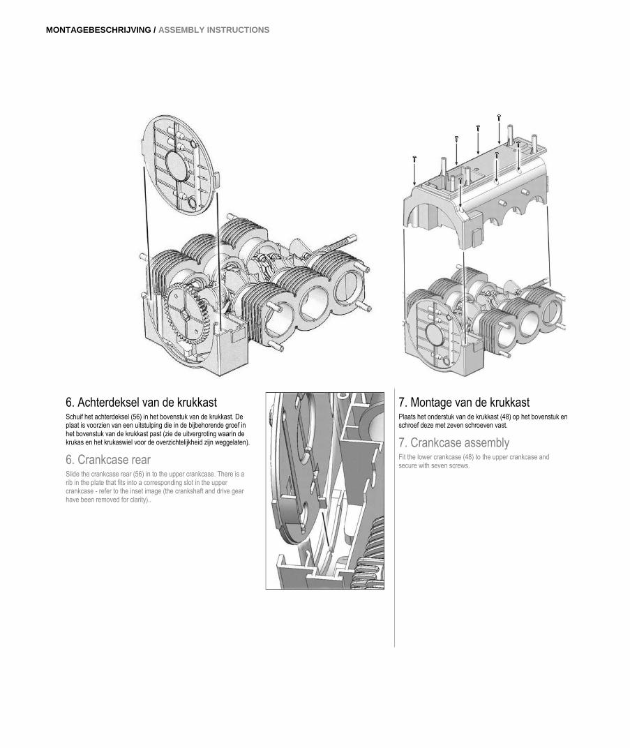
6. Achterdeksel van de krukkast Schuif het achterdeksel (56) in het bovenstuk van de krukkast. De plaat is voorzien van een uitstulping die in de bijbehorende groef in het bovenstuk van de krukkast past (zie de uitvergroting waarin de krukas en het krukaswiel voor de overzichtelijkheid zijn weggelaten).
6. Crankcase rear Slide the crankcase rear (56) in to the upper crankcase. There is a rib in the plate that fits into a corresponding slot in the upper crankcase - refer to the inset image (the crankshaft and drive gear have been removed for clarity)..
7. Montage van de krukkast Plaats het onderstuk van de krukkast (48) op het bovenstuk en schroef deze met zeven schroeven vast.
7. Crankcase assembly Fit the lower crankcase (48) to the upper crankcase and secure with seven screws.
10 | 11
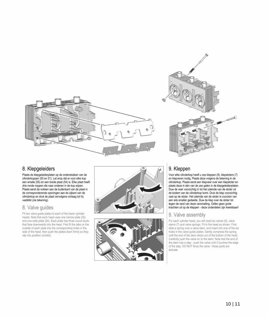
8. Klepgeleiders Plaats de klepgeleiderplaten op de onderstukken van de cilinderkoppen (50 en 51). Let erop dat er voor elke kop een smalle (55) en een brede plaat (54) is. Elke plaat heeft drie ronde noppen die naar onderen in de kop wijzen. Plaats eerst de nokken aan de buitenkant van de plaat in de corresponderende openingen aan de zijkant van de cilinderkop en druk de plaat vervolgens omlaag tot hij vastklikt (zie tekening).
8. Valve guides Fit two valve guide plates to each of the lower cylinder heads. Note that each head uses one narrow plate (55) and one wide plate (54). Each plate has three round studs that face downwards into the head. First fit the tabs on the outside of each plate into the corresponding holes in the side of the head, then push the plates down firmly so they clip into position (circled).
9. Kleppen Voor elke cilinderkop heeft u zes kleppen (9), klepstoters (7) en klepveren nodig. Plaats deze volgens de tekening in de cilinderkop. Plaats eerst een klepveer over een klepstoter en plaats deze in één van de zes gaten in de klepgeleiderplaten. Duw de veer voorzichtig in tot het uiteinde van de stoter uit de bodem van de cilinderkop komt. Druk de klep voorzichtig vast op de stoter. Het uiteinde van de stoter is voorzien van een iets smaller gedeelte. Duw de klep over de stoter tot tegen de rand van deze versmalling. Oefen geen grote krachten uit op de kleppen - deze onderdelen zijn kwetsbaar!
9. Valve assembly For each cylinder head, you will need six valves (9), valve stems (7) and valve springs. Fit to the head as shown. First slide a spring over a valve stem, and insert into one of the six holes in the valve guide plates. Gently compress the spring until the end of the stem sticks out of the bottom of the head. Carefully push the valve on to the stem. Note that the end of the stem has a step - push the valve until it touches the edge of the step. DO NOT force the valve - these parts are delicate.
MONTAGEBESCHRIJVING / ASSEMBLY INSTRUCTIONS
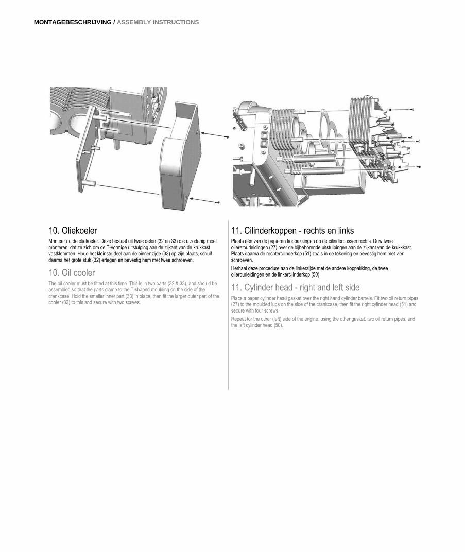
10. Oliekoeler Monteer nu de oliekoeler. Deze bestaat uit twee delen (32 en 33) die u zodanig moet monteren, dat ze zich om de T-vormige uitstulping aan de zijkant van de krukkast vastklemmen. Houd het kleinste deel aan de binnenzijde (33) op zijn plaats, schuif daarna het grote stuk (32) ertegen en bevestig hem met twee schroeven.
10. Oil cooler The oil cooler must be fitted at this time. This is in two parts (32 & 33), and should be assembled so that the parts clamp to the T-shaped moulding on the side of the crankcase. Hold the smaller inner part (33) in place, then fit the larger outer part of the cooler (32) to this and secure with two screws.
11. Cilinderkoppen - rechts en links Plaats één van de papieren koppakkingen op de cilinderbussen rechts. Duw twee olieretourleidingen (27) over de bijbehorende uitstulpingen aan de zijkant van de krukkkast. Plaats daarna de rechtercilinderkop (51) zoals in de tekening en bevestig hem met vier schroeven.
Herhaal deze procedure aan de linkerzijde met de andere koppakking, de twee olierourleidingen en de linkercilinderkop (50).
11. Cylinder head - right and left side Place a paper cylinder head gasket over the right hand cylinder barrels. Fit two oil return pipes (27) to the moulded lugs on the side of the crankcase, then fit the right cylinder head (51) and secure with four screws.
Repeat for the other (left) side of the engine, using the other gasket, two oil return pipes, and the left cylinder head (50).
12 | 13
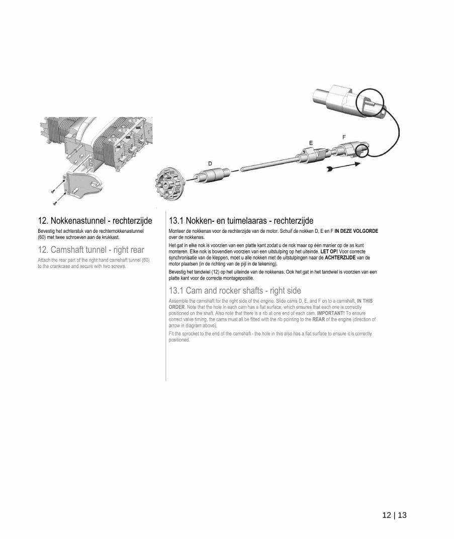
12. Nokkenastunnel - rechterzijde Bevestig het achterstuk van de rechternokkenastunnel (60) met twee schroeven aan de krukkast.
12. Camshaft tunnel - right rear Attach the rear part of the right hand camshaft tunnel (60) to the crankcase and secure with two screws.
13.1 Nokken- en tuimelaaras - rechterzijde Monteer de nokkenas voor de rechterzijde van de motor. Schuif de nokken D, E en F IN DEZE VOLGORDE over de nokkenas.
Het gat in elke nok is voorzien van een platte kant zodat u de nok maar op één manier op de as kunt monteren. Elke nok is bovendien voorzien van een uitstulping op het uiteinde. LET OP! Voor correcte synchronisatie van de kleppen, moet u alle nokken met de uitstulpingen naar de ACHTERZIJDE van de motor plaatsen (in de richting van de pijl in de tekening).
Bevestig het tandwiel (12) op het uiteinde van de nokkenas. Ook het gat in het tandwiel is voorzien van een platte kant voor de correcte montagepositie.
13.1 Cam and rocker shafts - right side Assemble the camshaft for the right side of the engine. Slide cams D, E, and F on to a camshaft, IN THIS ORDER. Note that the hole in each cam has a flat surface, which ensures that each one is correctly positioned on the shaft. Also note that there is a rib at one end of each cam. IMPORTANT! To ensure correct valve timing, the cams must all be fitted with the rib pointing to the REAR of the engine (direction of arrow in diagram above).
Fit the sprocket to the end of the camshaft - the hole in this also has a flat surface to ensure it is correctly positioned.
MONTAGEBESCHRIJVING / ASSEMBLY INSTRUCTIONS
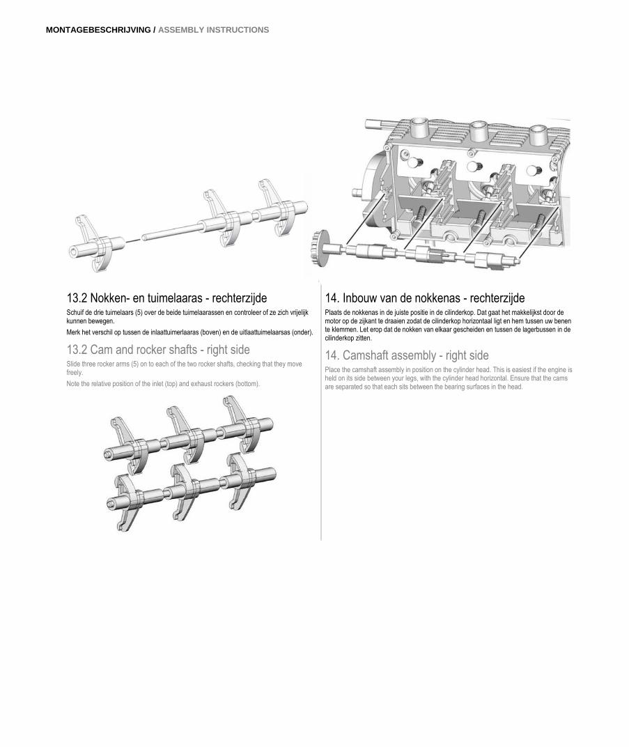
13.2 Nokken- en tuimelaaras - rechterzijde Schuif de drie tuimelaars (5) over de beide tuimelaarassen en controleer of ze zich vrijelijk kunnen bewegen.
Merk het verschil op tussen de inlaattuimerlaaras (boven) en de uitlaattuimelaarsas (onder).
13.2 Cam and rocker shafts - right side Slide three rocker arms (5) on to each of the two rocker shafts, checking that they move freely.
Note the relative position of the inlet (top) and exhaust rockers (bottom).
14. Inbouw van de nokkenas - rechterzijde Plaats de nokkenas in de juiste positie in de cilinderkop. Dat gaat het makkelijkst door de motor op de zijkant te draaien zodat de cilinderkop horizontaal ligt en hem tussen uw benen te klemmen. Let erop dat de nokken van elkaar gescheiden en tussen de lagerbussen in de cilinderkop zitten.
14. Camshaft assembly - right side Place the camshaft assembly in position on the cylinder head. This is easiest if the engine is held on its side between your legs, with the cylinder head horizontal. Ensure that the cams are separated so that each sits between the bearing surfaces in the head.
14 | 15
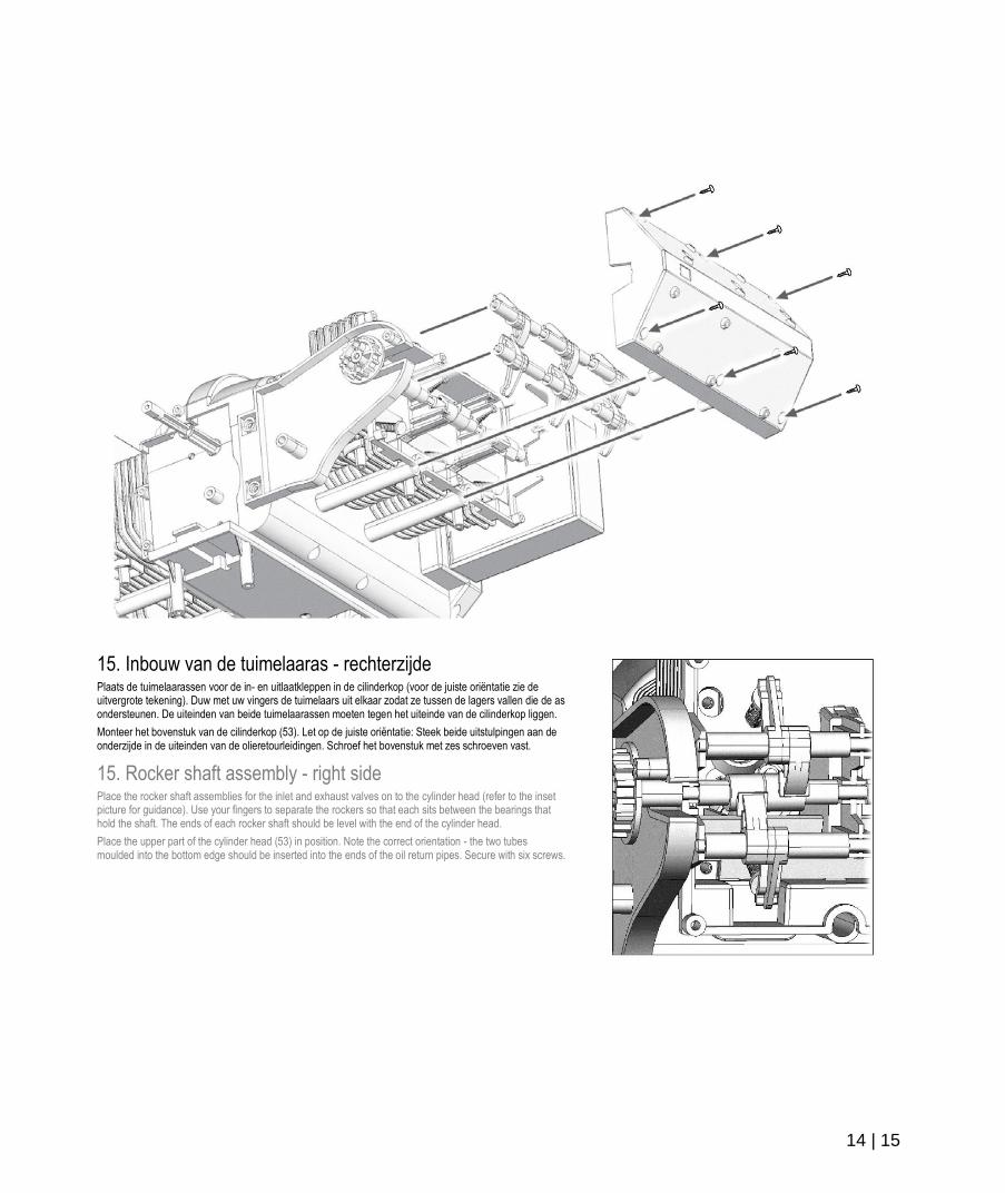
15. Inbouw van de tuimelaaras - rechterzijde Plaats de tuimelaarassen voor de in- en uitlaatkleppen in de cilinderkop (voor de juiste oriëntatie zie de uitvergrote tekening). Duw met uw vingers de tuimelaars uit elkaar zodat ze tussen de lagers vallen die de as ondersteunen. De uiteinden van beide tuimelaarassen moeten tegen het uiteinde van de cilinderkop liggen.
Monteer het bovenstuk van de cilinderkop (53). Let op de juiste oriëntatie: Steek beide uitstulpingen aan de onderzijde in de uiteinden van de olieretourleidingen. Schroef het bovenstuk met zes schroeven vast.
15. Rocker shaft assembly - right side Place the rocker shaft assemblies for the inlet and exhaust valves on to the cylinder head (refer to the inset picture for guidance). Use your fingers to separate the rockers so that each sits between the bearings that hold the shaft. The ends of each rocker shaft should be level with the end of the cylinder head.
Place the upper part of the cylinder head (53) in position. Note the correct orientation - the two tubes moulded into the bottom edge should be inserted into the ends of the oil return pipes. Secure with six screws.
MONTAGEBESCHRIJVING / ASSEMBLY INSTRUCTIONS
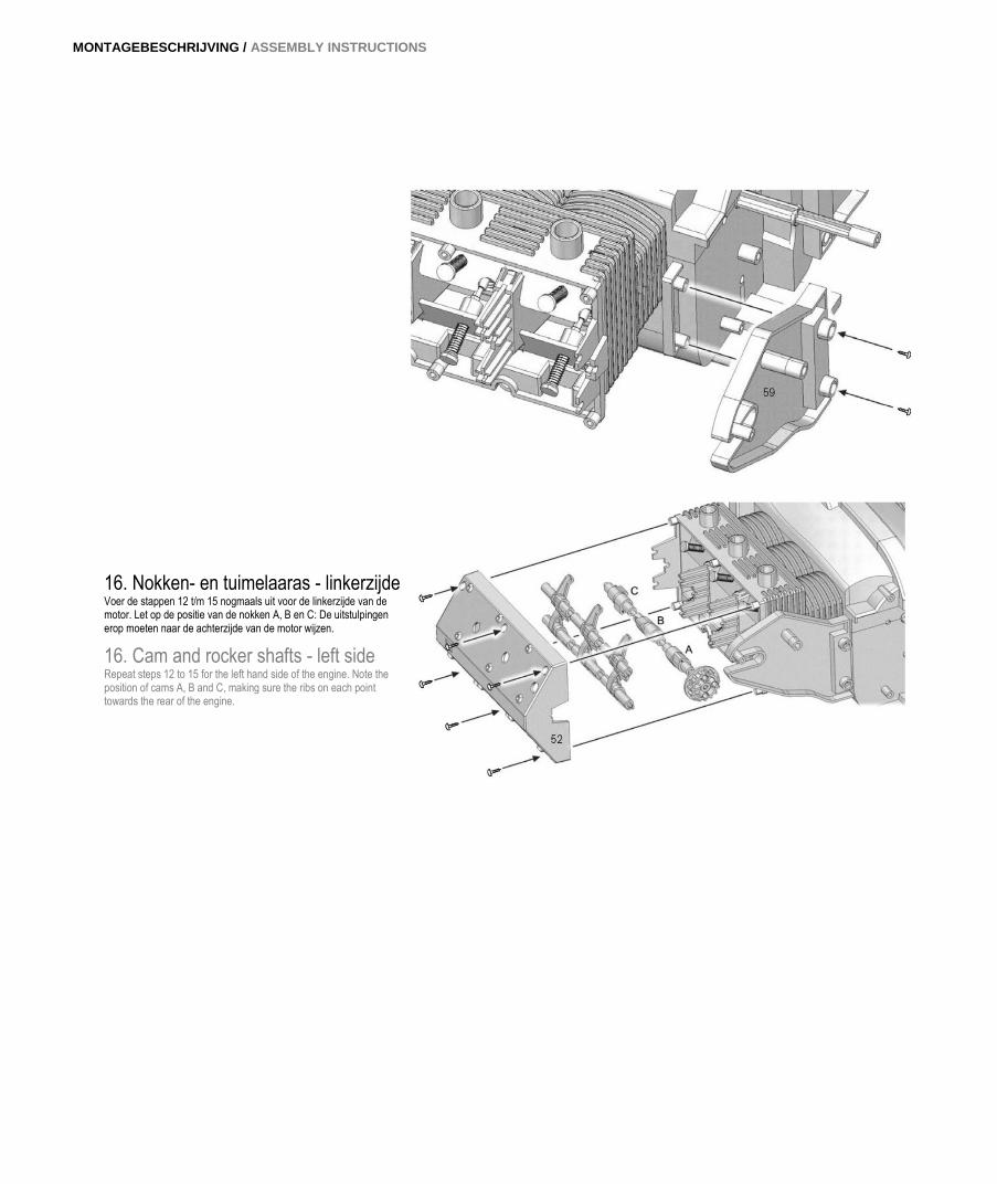
16. Nokken- en tuimelaaras - linkerzijde Voer de stappen 12 t/m 15 nogmaals uit voor de linkerzijde van de motor. Let op de positie van de nokken A, B en C: De uitstulpingen erop moeten naar de achterzijde van de motor wijzen.
16. Cam and rocker shafts - left side Repeat steps 12 to 15 for the left hand side of the engine. Note the position of cams A, B and C, making sure the ribs on each point towards the rear of the engine.
16 | 17
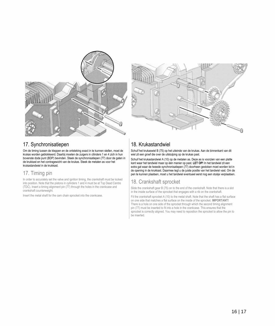
17. Synchronisatiepen Om de timing tussen de kleppen en de ontsteking exact in te kunnen stellen, moet de krukas worden geblokkeerd. Daarbij moeten de zuigers in cilinders 1 en 4 zich in hun bovenste dode punt (BDP) bevinden. Steek de synchronisatiepen (77) door de gaten in de krukkast en het contragewicht van de krukas. Steek de metalen as voor het krukastandwiel in de krukkast.
17. Timing pin In order to accurately set the valve and ignition timing, the crankshaft must be locked into position. Note that the pistons in cylinders 1 and 4 must be at Top Dead Centre (TDC). Insert a timing alignment pin (77) through the holes in the crankcase and crankshaft counterweight.
Insert the metal shaft for the cam chain sprocket into the crankcase.
18. Krukastandwiel Schuif het krukaswiel B (75) op het uiteinde van de krukas. Aan de binnenkant van dit wiel zit een groef die over de uitstulping op de krukas past.
Schuif het krukastandwiel A (10) op de metalen as. Deze as is voorzien van een platte kant waar het tandwiel maar op één manier op past. LET OP! In het tandwiel zit een extra gat waar de tweede synchronisatiepen (77) doorheen gestoken moet worden tot in de opening in de krukkast. Daarmee legt u de juiste positie van het tandwiel vast. Om de pen te kunnen plaatsen, moet u het tandwiel eventueel eerst nog een stukje verplaatsen.
18. Crankshaft sprocket Slide the crankshaft gear B (75) on to the end of the crankshaft. Note that there is a slot in the inside surface of the sprocket that engages with a rib on the crankshaft.
Fit the crankshaft sprocket A (10) to the metal shaft. Note that the shaft has a flat surface on one side that matches a flat surface on the inside of the sprocket. IMPORTANT! There is a hole on one side of the sprocket through which the second timing alignment pin (77) must be inserted to fit into a hole in the crankcase. This ensures that the sprocket is correctly aligned. You may need to reposition the sprocket to allow the pin to be inserted.
MONTAGEBESCHRIJVING / ASSEMBLY INSTRUCTIONS
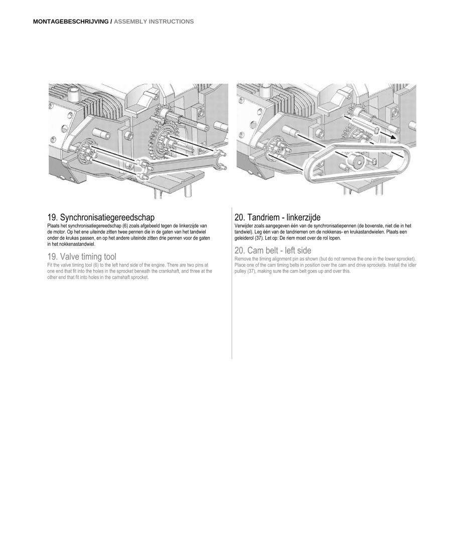
19. Synchronisatiegereedschap Plaats het synchronisatiegereedschap (6) zoals afgebeeld tegen de linkerzijde van de motor. Op het ene uiteinde zitten twee pennen die in de gaten van het tandwiel onder de krukas passen, en op het andere uiteinde zitten drie pennen voor de gaten in het nokkenastandwiel.
19. Valve timing tool Fit the valve timing tool (6) to the left hand side of the engine. There are two pins at one end that fit into the holes in the sprocket beneath the crankshaft, and three at the other end that fit into holes in the camshaft sprocket.
20. Tandriem - linkerzijde Verwijder zoals aangegeven één van de synchronisatiepennen (de bovenste, niet die in het tandwiel). Leg één van de tandriemen om de nokkenas- en krukastandwielen. Plaats een geleiderol (37). Let op: De riem moet over de rol lopen.
20. Cam belt - left side Remove the timing alignment pin as shown (but do not remove the one in the lower sprocket). Place one of the cam timing belts in position over the cam and drive sprockets. Install the idler pulley (37), making sure the cam belt goes up and over this.
18 | 19
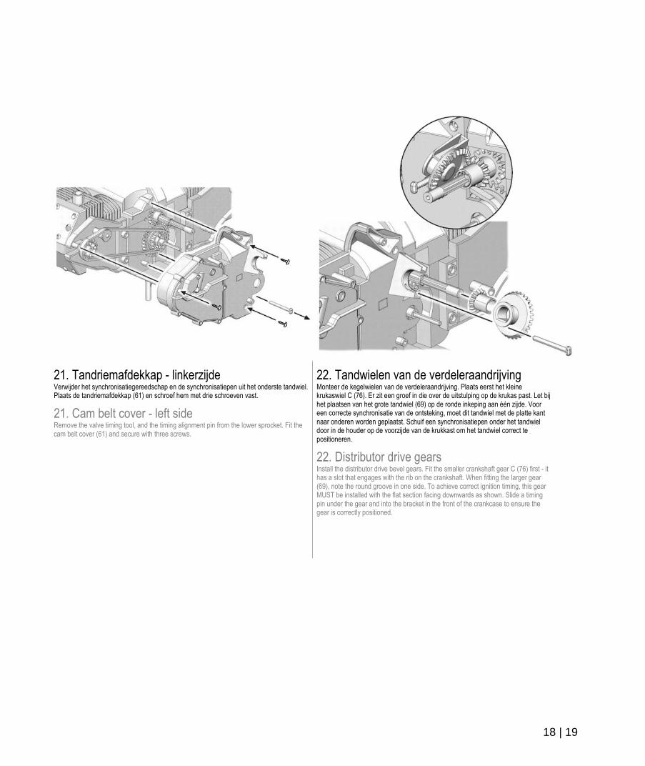
21. Tandriemafdekkap - linkerzijde Verwijder het synchronisatiegereedschap en de synchronisatiepen uit het onderste tandwiel. Plaats de tandriemafdekkap (61) en schroef hem met drie schroeven vast.
21. Cam belt cover - left side Remove the valve timing tool, and the timing alignment pin from the lower sprocket. Fit the cam belt cover (61) and secure with three screws.
22. Tandwielen van de verdeleraandrijving Monteer de kegelwielen van de verdeleraandrijving. Plaats eerst het kleine krukaswiel C (76). Er zit een groef in die over de uitstulping op de krukas past. Let bij het plaatsen van het grote tandwiel (69) op de ronde inkeping aan één zijde. Voor een correcte synchronisatie van de ontsteking, moet dit tandwiel met de platte kant naar onderen worden geplaatst. Schuif een synchronisatiepen onder het tandwiel door in de houder op de voorzijde van de krukkast om het tandwiel correct te positioneren.
22. Distributor drive gears Install the distributor drive bevel gears. Fit the smaller crankshaft gear C (76) first - it has a slot that engages with the rib on the crankshaft. When fitting the larger gear (69), note the round groove in one side. To achieve correct ignition timing, this gear MUST be installed with the flat section facing downwards as shown. Slide a timing pin under the gear and into the bracket in the front of the crankcase to ensure the gear is correctly positioned.
MONTAGEBESCHRIJVING / ASSEMBLY INSTRUCTIONS
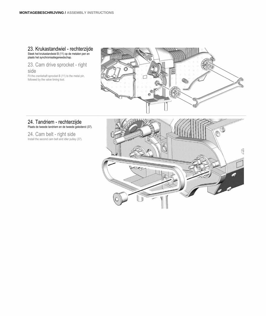
23. Krukastandwiel - rechterzijde Steek het krukastandwiel B (11) op de metalen pen en plaats het synchronisatiegereedschap.
23. Cam drive sprocket - right side Fit the crankshaft sprocket B (11) to the metal pin, followed by the valve timing tool.
24. Tandriem - rechterzijde Plaats de tweede tandriem en de tweede geleiderol (37).
24. Cam belt - right side Install the second cam belt and idler pulley (37).
20 | 21
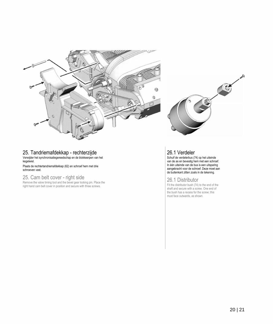
25. Tandriemafdekkap - rechterzijde Verwijder het synchronisatiegereedschap en de blokkeerpen van het kegelwiel.
Plaats de rechtertandriemafdekkap (62) en schroef hem met drie schroeven vast.
25. Cam belt cover - right side Remove the valve timing tool and the bevel gear locking pin. Place the right hand cam belt cover in position and secure with three screws.
26.1 Verdeler Schuif de verdelerbus (74) op het uiteinde van de as en bevestig hem met een schroef. In één uiteinde van de bus is een uitsparing aangebracht voor de schroef. Deze moet aan de buitenkant zitten zoals in de tekening.
26.1 Distributor Fit the distributor bush (74) to the end of the shaft and secure with a screw. One end of the bush has a recess for the screw; this must face outwards, as shown.
MONTAGEBESCHRIJVING / ASSEMBLY INSTRUCTIONS
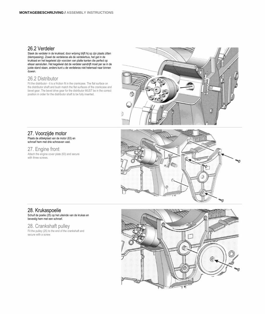
26.2 Verdeler Steek de verdeler in de krukkast; door wrijving blijft hij op zijn plaats zitten (klempassing). Zowel de verdeleras als de verdelerbus, het gat in de krukkast en het kegelwiel zijn voorzien van platte kanten die perfect op elkaar aansluiten. Het kegelwiel dat de verdeler aandrijft moet per se in de juiste stand staan, anders kunt u de verdeleras niet helemaal naar binnen duwen.
26.2 Distributor Fit the distributor - it is a friction fit in the crankcase. The flat surface on the distributor shaft and bush match the flat surfaces of the crankcase and bevel gear. The bevel drive gear for the distributor MUST be in the correct position in order for the distributor shaft to be fully inserted.
27. Voorzijde motor Plaats de afdekplaat van de motor (63) en schroef hem met drie schroeven vast.
27. Engine front Attach the engine cover plate (63) and secure with three screws.
28. Krukaspoelie Schuif de poelie (25) op het uiteinde van de krukas en bevestig hem met een schroef.
28. Crankshaft pulley Fit the pulley (25) to the end of the crankshaft and secure with a screw.
22 | 23
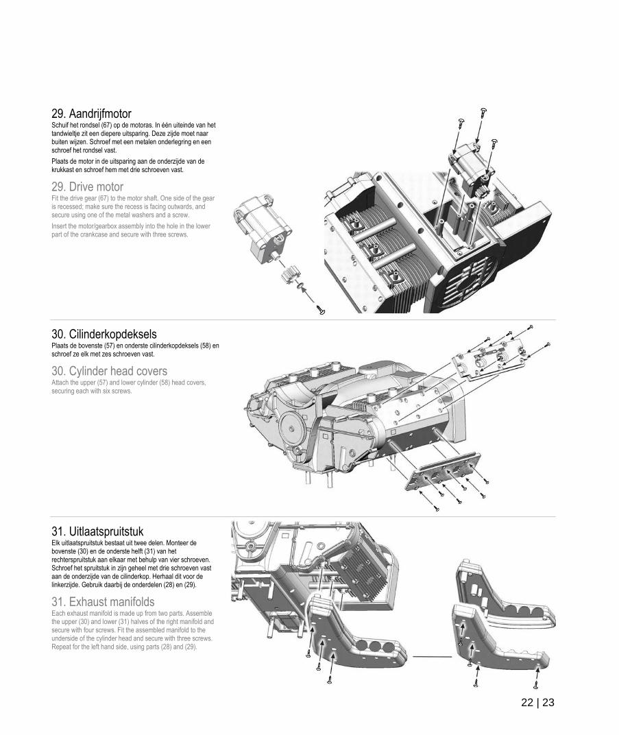
29. Aandrijfmotor Schuif het rondsel (67) op de motoras. In één uiteinde van het tandwieltje zit een diepere uitsparing. Deze zijde moet naar buiten wijzen. Schroef met een metalen onderlegring en een schroef het rondsel vast.
Plaats de motor in de uitsparing aan de onderzijde van de krukkast en schroef hem met drie schroeven vast.
29. Drive motor Fit the drive gear (67) to the motor shaft. One side of the gear is recessed; make sure the recess is facing outwards, and secure using one of the metal washers and a screw.
Insert the motor/gearbox assembly into the hole in the lower part of the crankcase and secure with three screws.
30. Cilinderkopdeksels Plaats de bovenste (57) en onderste cilinderkopdeksels (58) en schroef ze elk met zes schroeven vast.
30. Cylinder head covers Attach the upper (57) and lower cylinder (58) head covers, securing each with six screws.
31. Uitlaatspruitstuk Elk uitlaatspruitstuk bestaat uit twee delen. Monteer de bovenste (30) en de onderste helft (31) van het rechterspruitstuk aan elkaar met behulp van vier schroeven. Schroef het spruitstuk in zijn geheel met drie schroeven vast aan de onderzijde van de cilinderkop. Herhaal dit voor de linkerzijde. Gebruik daarbij de onderdelen (28) en (29).
31. Exhaust manifolds Each exhaust manifold is made up from two parts. Assemble the upper (30) and lower (31) halves of the right manifold and secure with four screws. Fit the assembled manifold to the underside of the cylinder head and secure with three screws. Repeat for the left hand side, using parts (28) and (29).
MONTAGEBESCHRIJVING / ASSEMBLY INSTRUCTIONS
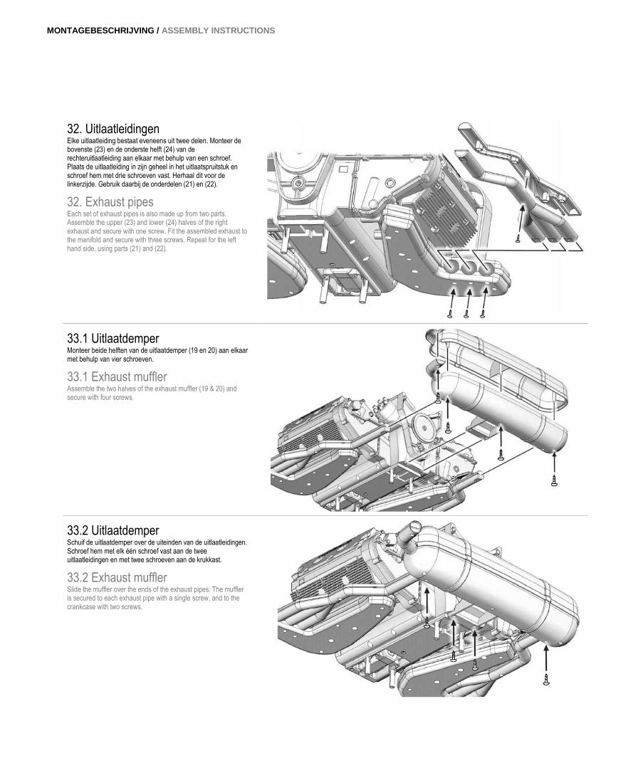
32. Uitlaatleidingen Elke uitlaatleiding bestaat eveneens uit twee delen. Monteer de bovenste (23) en de onderste helft (24) van de rechteruitlaatleiding aan elkaar met behulp van een schroef. Plaats de uitlaatleiding in zijn geheel in het uitlaatspruitstuk en schroef hem met drie schroeven vast. Herhaal dit voor de linkerzijde. Gebruik daarbij de onderdelen (21) en (22).
32. Exhaust pipes Each set of exhaust pipes is also made up from two parts. Assemble the upper (23) and lower (24) halves of the right exhaust and secure with one screw. Fit the assembled exhaust to the manifold and secure with three screws. Repeat for the left hand side, using parts (21) and (22).
33.1 Uitlaatdemper Monteer beide helften van de uitlaatdemper (19 en 20) aan elkaar met behulp van vier schroeven.
33.1 Exhaust muffler Assemble the two halves of the exhaust muffler (19 & 20) and secure with four screws.
33.2 Uitlaatdemper Schuif de uitlaatdemper over de uiteinden van de uitlaatleidingen. Schroef hem met elk één schroef vast aan de twee uitlaatleidingen en met twee schroeven aan de krukkast.
33.2 Exhaust muffler Slide the muffler over the ends of the exhaust pipes. The muffler is secured to each exhaust pipe with a single screw, and to the crankcase with two screws.
24 | 25
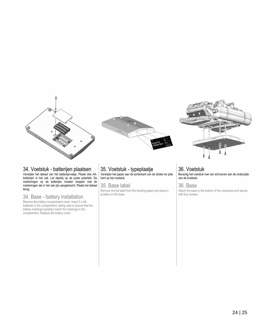
34. Voetstuk - batterijen plaatsen Verwijder het deksel van het batterijenvakje. Plaats drie AA-batterijen in het vak. Let daarbij op de juiste polariteit: De markeringen op de batterijen moeten kloppen met de markeringen die in het vak zijn aangebracht. Plaats het deksel terug.
34. Base - battery installation Remove the battery compartment cover. Insert 3 x AA batteries in the compartment, taking care to ensure that the battery markings (polarity) match the markings in the compartment. Replace the battery cover.
35. Voetstuk - typeplaatje Verwijder het papier aan de achterkant van de sticker en plak hem op het voetstuk.
35. Base label Remove the foil label from the backing paper and place in position on the base.
36. Voetstuk Bevestig het voetstuk met vier schroeven aan de onderzijde van de krukkast.
36. Base Attach the base to the bottom of the crankcase and secure with four screws.
MONTAGEBESCHRIJVING / ASSEMBLY INSTRUCTIONS
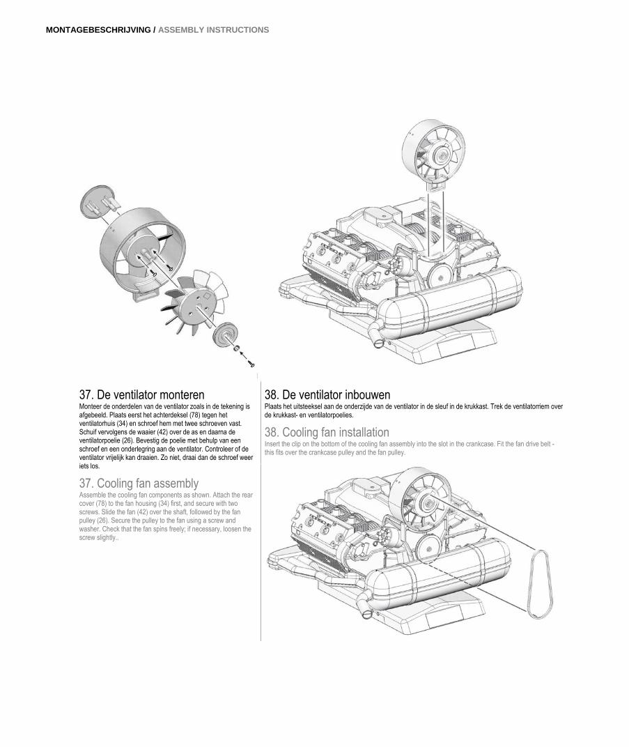
37. De ventilator monteren Monteer de onderdelen van de ventilator zoals in de tekening is afgebeeld. Plaats eerst het achterdeksel (78) tegen het ventilatorhuis (34) en schroef hem met twee schroeven vast. Schuif vervolgens de waaier (42) over de as en daarna de ventilatorpoelie (26). Bevestig de poelie met behulp van een schroef en een onderlegring aan de ventilator. Controleer of de ventilator vrijelijk kan draaien. Zo niet, draai dan de schroef weer iets los.
37. Cooling fan assembly Assemble the cooling fan components as shown. Attach the rear cover (78) to the fan housing (34) first, and secure with two screws. Slide the fan (42) over the shaft, followed by the fan pulley (26). Secure the pulley to the fan using a screw and washer. Check that the fan spins freely; if necessary, loosen the screw slightly..
38. De ventilator inbouwen Plaats het uitsteeksel aan de onderzijde van de ventilator in de sleuf in de krukkast. Trek de ventilatorriem over de krukkast- en ventilatorpoelies.
38. Cooling fan installation Insert the clip on the bottom of the cooling fan assembly into the slot in the crankcase. Fit the fan drive belt - this fits over the crankcase pulley and the fan pulley.
26 | 27
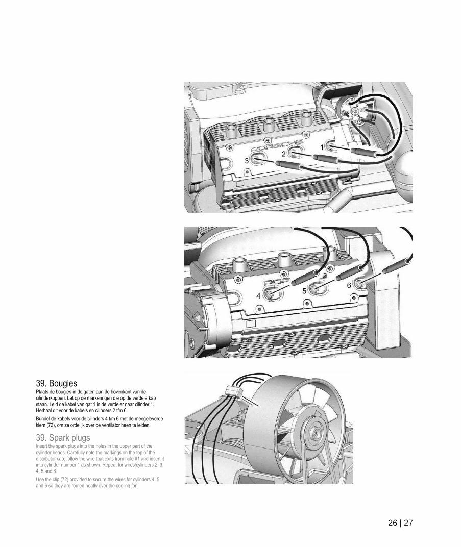
39. Bougies Plaats de bougies in de gaten aan de bovenkant van de cilinderkoppen. Let op de markeringen die op de verdelerkap staan. Leid de kabel van gat 1 in de verdeler naar cilinder 1. Herhaal dit voor de kabels en cilinders 2 t/m 6.
Bundel de kabels voor de cilinders 4 t/m 6 met de meegeleverde klem (72), om ze ordelijk over de ventilator heen te leiden.
39. Spark plugs Insert the spark plugs into the holes in the upper part of the cylinder heads. Carefully note the markings on the top of the distributor cap; follow the wire that exits from hole #1 and insert it into cylinder number 1 as shown. Repeat for wires/cylinders 2, 3, 4, 5 and 6.
Use the clip (72) provided to secure the wires for cylinders 4, 5 and 6 so they are routed neatly over the cooling fan.
MONTAGEBESCHRIJVING / ASSEMBLY INSTRUCTIONS
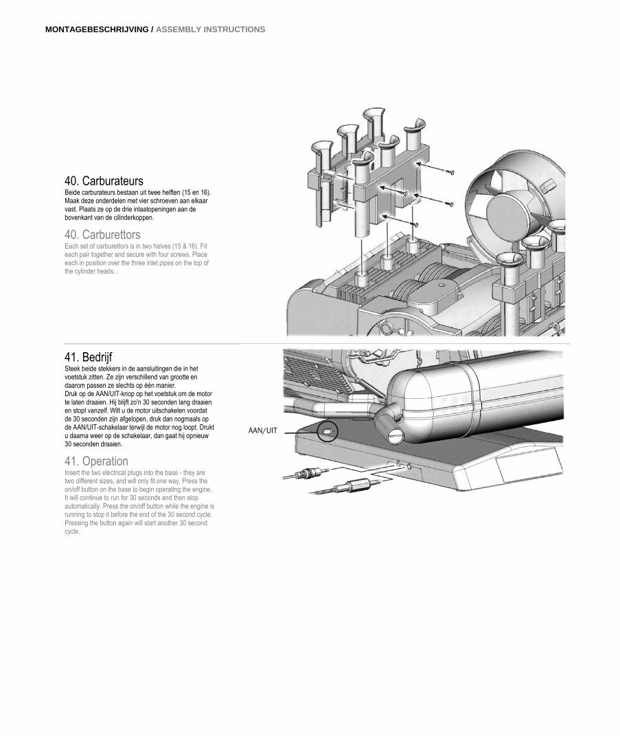
40. Carburateurs Beide carburateurs bestaan uit twee helften (15 en 16). Maak deze onderdelen met vier schroeven aan elkaar vast. Plaats ze op de drie inlaatopeningen aan de bovenkant van de cilinderkoppen.
40. Carburettors Each set of carburettors is in two halves (15 & 16). Fit each pair together and secure with four screws. Place each in position over the three inlet pipes on the top of the cylinder heads...
41. Bedrijf Steek beide stekkers in de aansluitingen die in het voetstuk zitten. Ze zijn verschillend van grootte en daarom passen ze slechts op één manier. Druk op de AAN/UIT-knop op het voetstuk om de motor te laten draaien. Hij blijft zo'n 30 seconden lang draaien en stopt vanzelf. Wilt u de motor uitschakelen voordat de 30 seconden zijn afgelopen, druk dan nogmaals op de AAN/UIT-schakelaar terwijl de motor nog loopt. Drukt u daarna weer op de schakelaar, dan gaat hij opnieuw 30 seconden draaien.
41. Operation Insert the two electrical plugs into the base - they are two different sizes, and will only fit one way. Press the on/off button on the base to begin operating the engine. It will continue to run for 30 seconds and then stop automatically. Press the on/off button while the engine is running to stop it before the end of the 30 second cycle. Pressing the button again will start another 30 second cycle.
AAN/UIT


Geproduceerd met toestemming van de firma Dr. Ing. h.c. F. Porsche AG.
Motor Model designed and developed by John Anson
Aanvullende benodigdheden: 3x 1,5 V AA batterijen (penlite) Additionally required: 3 x 1.5 V batteries (AA)
MAP09028016 Ga voor meer online Franzis-producten naar www.franzis.de More Franzis products online www.franzis.de
© 2016 Franzis Verlag GmbH, Richard-Reitzner-Allee 2, D-85540 Haar, Duitsland
Wijzigingen, vergissingen en drukfouten voorbehouden. Subject to innovation, errors and printing errors. 2016/01
Niet geschikt voor kinderen jonger dan 14 jaar!
This is not a toy! Not suitable for children under 14 years.
Montagebeschrijving Assembly instructions
EDITION PORSCHE MUSEUM